

Mitsubishi Heavy Industries SRK05CM, SRK05CM-3, SRK09CM-3, SRK09CM-4, SRK09CM-5 Technical Manual
...
RESIDENTIAL AIR-CONDITIONING
TECHNICAL MANUAL & PARTS LIST
WALL MOUNTED TYPE
RESIDENTIAL AIR-CONDITIONERS
(Split system, air cooled cooling only type)
SRK05CM, 05CM-3
SRK05CMP-3
SRK09CM-3, 09CM-4, 09CM-5
SRK09CMP-3, 09CMP-4
SRK12CM-3, 12CM-4, 12CM-5
Manual No.'13•SRK-T-141
-
1
-
'13•SRK-T-141
TECHNICAL MANUAL

-
2
-
'13•SRK-T-141
'10 • SRK-T-099
CONTENTS
1. SPECIFICATIONS .................................................................................... 4
(2) Outdoor units ...................................................................................... 17
(3) Wireless remote control
...................................................................... 19
........................................................................ 15
(1) Indoor units ......................................................................................... 15
2. EXTERIOR DIMENSIONS
3. ELECTRICAL WIRING ............................................................................. 20
(1) Indoor units ......................................................................................... 20
(2) Outdoor units ...................................................................................... 21
....................................................... 24
5. RANGE OF USAGE & LIMITATIONS
4. PIPING SYSTEM ..................................................................................... 23
............................................................................... 26
6. APPLICATION DATA
7. OUTLINE OF OPERATION CONTROL BY MICROCOMPUTER ........... 40
(6) Timer operation
................................................................................. 43
(5) Flap control ....................................................................................... 43
...................................................... 42(4) Custom cord switching procedure
........................................................................ 42(3) Auto restart function
(2) Unit ON/OFF button
.......................................................................... 42
(1) Operation control function by remote control
..................................... 40
(8) Outline of automatic operation .......................................................... 44
(7) Outline of cooling operation .............................................................. 44
(9) Protective control function
.................................................................. 45
.............................................................................. 46
.................... 47
(4) Troubleshooting procedure (If the air conditioner runs)
(3) Troubleshooting procedure
(If the air conditioner does not run at all)
....... 46
(1) Cautions
............................................................................................ 46
(2) Items to check before troubleshooting ................................................ 46
(5) Self-diagnosis table ............................................................................ 47
(6) Inspection procedures corresponding to detail of trouble ................... 48
8. MAINTENANCE DATA

-
3
-
'13•SRK-T-141
'10 • SRK-T-099
(7)
Phenomenon observed after shortcircuit, wire breakage on sensor
........ 49
■How to read the model name
Example: SRK 05 C
Series code
Cooling only type
Product capacity
Model name SRK : Wall mounted type
SRC : Outdoor unit
MP
(8) How to make sure of wireless remote control ..................................... 50
-
4
-
'13•SRK-T-141
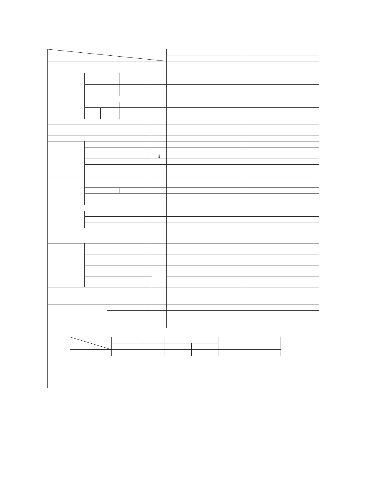
1. SPECIFICATIONS
Model
Item
SRK05CM
Indoor unit SRK05CM Outdoor unit SRC05CM
Cooling capacity (1) W 1500
Power supply 1 Phase, 220V, 50Hz
Operation
data (1)
Power
consumption
Cooling kW 0.42
Running
current
Cooling
A
2.0
Inrush current 9.5
COP Cooling 3.57
Noise
level
Cooling Sound level dB(A) 42 47
Exterior dimensions (Height x Width x Depth) mm 262 x 615 x 210 435 x 645 (+50) x 275
Exterior appearance
(Munsell color)
Fine snow
(8.0Y 9.3/0.1) near equivalent
Stucco white
(4.2Y 7.5/1.1) near equivalent
Net weight kg 6 19
Refrigerant
equipment
Compressor type & Q'ty — RMC201A009 (Rotary type) x 1
Motor (Starting method) kW — 0.35 (PSC)
Refrigerant oil 0.29 (SUNISO 4GSI or ATMOS NM56M)
Refrigerant (3) kg R22 0.40 (Pre-Charged up to the piping length of 7.5m)
Heat exchanger Louver fins & inner grooved tubing Louver fins & inner grooved tubing
Refrigerant control Capillary tubes
Air handling
equipment
Fan type & Q'ty Cross flow fan x 1 Propeller fan x 1
Motor W 17 22
Air flow Cooling m3/min 8.5 23.0
Fresh air intake Not possible —
Air filter, Quality / Quantity Polypropylene net (washable) x 1 —
Shock & vibration absorber — Cushion rubber (for compressor)
Operation
control
Operation switch Wireless-Remote control —
Room temperature control Microcomputer thermostat —
Operation Display RUN : Green, TIMER : Yellow
Safety devices
Compressor overheat protection, Overcurrent protection,
Frost protection, Serial signal error protection, Indoor fan motor error protection,
Cooling overload protection
Installation
data
Refrigerant piping size (O.D) mm Liquid line: φ6.35 (1/4") Gas line: φ9.52 (3/8")
Connecting method Flare connecting
Attached length of piping m
Liquid line : 0.46
Gas line : 0.40
—
Insulation for piping Necessary (Both sides), independent
Refrigerant line (one way) length
m
Max. 15
Vertical height difference between
outdoor unit and indoor unit
Max.5 (Outdoor unit is higher)
Max.5 (Outdoor unit is lower)
Drain hose Connectable (VP 16) —
Power cable —
Recommended breaker size A 10
Connection wiring
Size x Core number 1.5mm2 x 3 cores (Including earth cable)
Connecting method Terminal block (Screw fixing type)
Accessories (included) Mounting kit
Option parts —
Note (1) The data are measured at the following conditions.
Item
Operation
Indoor air temperature Outdoor air temperature
Standards
DB WB DB WB
Cooling 27˚C 19˚C 35˚C 24˚C JIS C 9612, TISI 1155, 2134, 812
(2) This air-conditioner is manufactured and tested in conformity with the TISI.
(3) The operation data are applied to the 220V districts.
(4) The refrigerant quantity to be charged includes the refrigerant in 7.5m connecting piping.
(Purging is not required even for the short piping.)
If the piping length is 7.5m to 15m, additional refrigerant is 10g per each 1m longer than 7.5m.
The pipe length is 7.5m.

-
5
-
'13•SRK-T-141
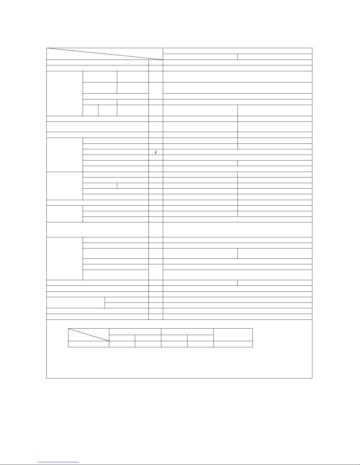
Model
Item
SRK05CM-3
Indoor unit SRK05CM-3 Outdoor unit SRC05CM-3
Cooling capacity (1) W 1465
Power supply 1 Phase, 220 - 240V, 50Hz
Operation
data (1)
Power
consumption
Cooling kW 0.375
Running
current
Cooling
A
1.8
Inrush current 9.5
COP Cooling 3.91
Noise
level
Cooling Sound level dB(A) 42 48
Exterior dimensions (Height x Width x Depth) mm 262 x 615 x 210 435 x 645 (+50) x 275
Exterior appearance
(Munsell color)
Fine snow
(8.0Y 9.3/0.1) near equivalent
Stucco white
(4.2Y 7.5/1.1) near equivalent
Net weight kg 6 20
Refrigerant
equipment
Compressor type & Q'ty — RMC201A055 (Rotary type) x 1
Motor (Starting method) kW — 0.35 (PSC)
Refrigerant oil 0.23 (SUNISO 4GSI or ATMOS NM56M)
Refrigerant (3) kg R22 0.45 (Pre-Charged up to the piping length of 5.0m)
Heat exchanger Louver fins & inner grooved tubing Louver fins & inner grooved tubing
Refrigerant control Capillary tubes
Air handling
equipment
Fan type & Q'ty Cross flow fan x 1 Propeller fan x 1
Motor W 17 22
Air flow Cooling m3/min 8.5 23.0
Fresh air intake Not possible —
Air filter, Quality / Quantity Polypropylene net (washable) x 1 —
Shock & vibration absorber — Cushion rubber (for compressor)
Operation
control
Operation switch Wireless-Remote control —
Room temperature control Microcomputer thermostat —
Operation Display RUN : Green, TIMER : Yellow
Safety devices
Compressor overheat protection, Overcurrent protection,
Frost protection, Serial signal error protection, Indoor fan motor error protection,
Cooling overload protection
Installation
data
Refrigerant piping size (O.D) mm Liquid line: φ6.35 (1/4") Gas line: φ9.52 (3/8")
Connecting method Flare connecting
Attached length of piping m
Liquid line : 0.46
Gas line : 0.40
—
Insulation for piping Necessary (Both sides), independent
Refrigerant line (one way) length
m
Max. 15
Vertical height difference between
outdoor unit and indoor unit
Max.5 (Outdoor unit is higher)
Max.5 (Outdoor unit is lower)
Drain hose Connectable (VP 16) —
Power cable —
Recommended breaker size A 10
Connection wiring
Size x Core number 1.5mm2 x 3 cores (Including earth cable)
Connecting method Terminal block (Screw fixing type)
Accessories (included) Mounting kit
Option parts —
Note (1) The data are measured at the following conditions.
Item
Operation
Indoor air temperature Outdoor air temperature
Standards
DB WB DB WB
Cooling 27˚C 19˚C 35˚C 24˚C ISO-T1, JIS C 9612
(2) This air-conditioner is manufactured and tested in conformity with the ISO.
(3) The operation data are applied to the 220V districts.
(4) The refrigerant quantity to be charged includes the refrigerant in 5.0m connecting piping.
(Purging is not required even for the short piping.)
If the piping length is 5m to 15m, additional refrigerant is 10g per each 1m longer than 5m.
The pipe length is 5.0m.

-
6
-
'13•SRK-T-141
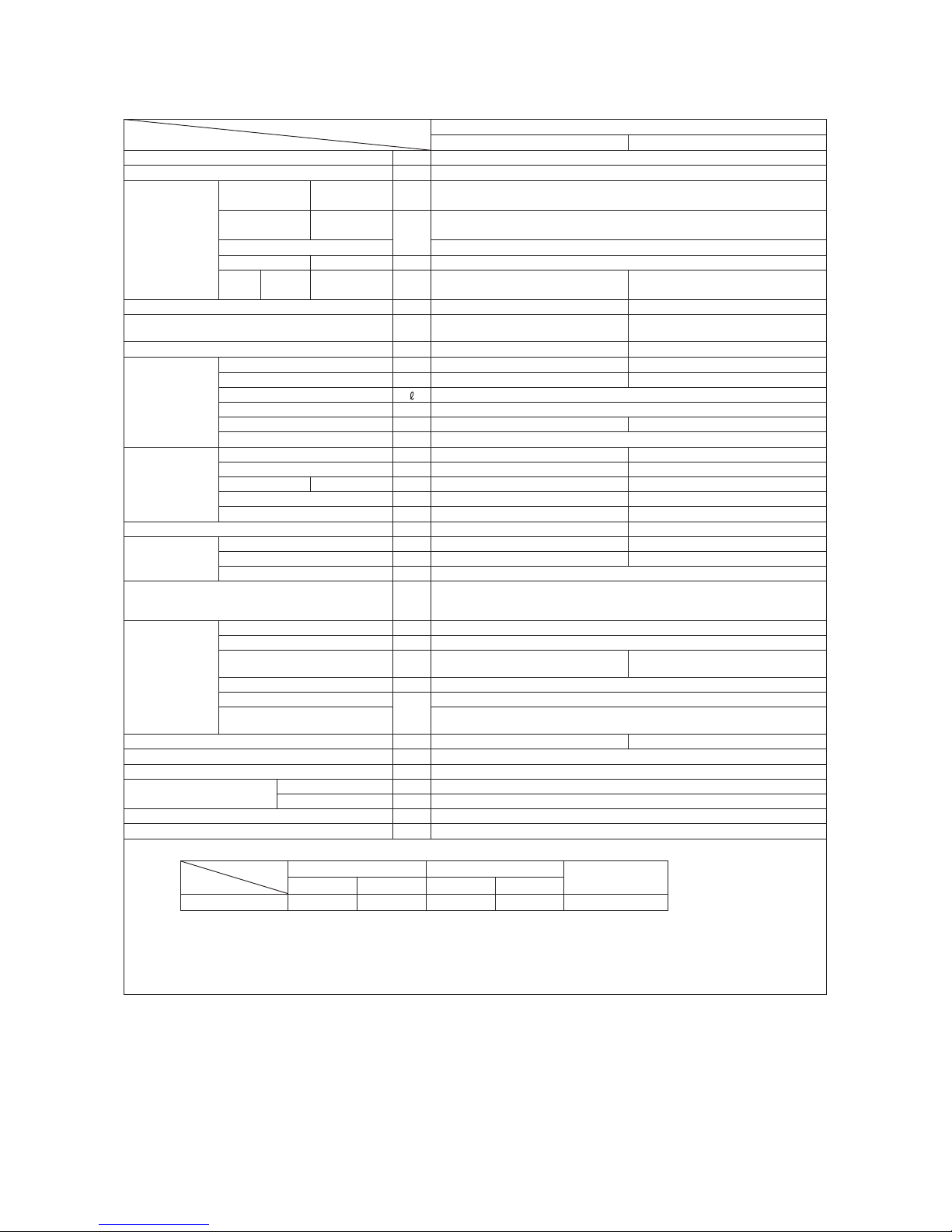
Model
Item
SRK05CMP-3
Indoor unit SRK05CMP-3 Outdoor unit SRC05CMP-3
Cooling capacity (1) W 1465
Power supply 1 Phase, 220 - 240V, 50Hz
Operation
data (1)
Power
consumption
Cooling kW 0.49
Running
current
Cooling
A
2.3 / 2.2
Inrush current 9.5
COP Cooling 2.99
Noise
level
Cooling Sound level dB(A) 42 47
Exterior dimensions (Height x Width x Depth) mm 262 x 615 x 210 435 x 645 (+50) x 275
Exterior appearance
(Munsell color)
Fine snow
(8.0Y 9.3/0.1) near equivalent
Stucco white
(4.2Y 7.5/1.1) near equivalent
Net weight kg 6 19
Refrigerant
equipment
Compressor type & Q'ty — RMC201A009 (Rotary type) x 1
Motor (Starting method) kW — 0.35 (PSC)
Refrigerant oil 0.29 (SUNISO 4GSI or ATMOS NM56M)
Refrigerant (3) kg R22 0.34 (Pre-Charged up to the piping length of 5.0m)
Heat exchanger Louver fins & inner grooved tubing Louver fins & inner grooved tubing
Refrigerant control Capillary tubes
Air handling
equipment
Fan type & Q'ty Cross flow fan x 1 Propeller fan x 1
Motor W 17 22
Air flow Cooling m3/min 8.5 20.0
Fresh air intake Not possible —
Air filter, Quality / Quantity Polypropylene net (washable) x 1 —
Shock & vibration absorber — Cushion rubber (for compressor)
Operation
control
Operation switch Wireless-Remote control —
Room temperature control Microcomputer thermostat —
Operation Display RUN : Green, TIMER : Yellow
Safety devices
Compressor overheat protection, Overcurrent protection,
Frost protection, Serial signal error protection, Indoor fan motor error protection,
Cooling overload protection
Installation
data
Refrigerant piping size (O.D) mm Liquid line: φ6.35 (1/4") Gas line: φ9.52 (3/8")
Connecting method Flare connecting
Attached length of piping m
Liquid line : 0.46
Gas line : 0.40
—
Insulation for piping Necessary (Both sides), independent
Refrigerant line (one way) length
m
Max. 15
Vertical height difference between
outdoor unit and indoor unit
Max.5 (Outdoor unit is higher)
Max.5 (Outdoor unit is lower)
Drain hose Connectable (VP 16) —
Power cable —
Recommended breaker size A 10
Connection wiring
Size x Core number 1.5mm2 x 3 cores (Including earth cable)
Connecting method Terminal block (Screw fixing type)
Accessories (included) Mounting kit
Option parts —
Note (1) The data are measured at the following conditions.
Item
Operation
Indoor air temperature Outdoor air temperature
Standards
DB WB DB WB
Cooling 27˚C 19˚C 35˚C 24˚C ISO-T1, JIS C 9612
(2) This air-conditioner is manufactured and tested in conformity with the ISO.
(3) The operation data are applied to the 220 / 230V districts respectively.
(4) The refrigerant quantity to be charged includes the refrigerant in 5.0m connecting piping.
(Purging is not required even for the short piping.)
If the piping length is 5m to 15m, additional refrigerant is 10g per each 1m longer than 5m.
The pipe length is 5.0m.
-
7
-
'13•SRK-T-141
Model
Item
SRK09CM-3
Indoor unit SRK09CM-3 Outdoor unit SRC09CM-3
Cooling capacity (1) W 2638
Power supply 1 Phase, 220 - 240V, 50Hz
Operation
data (1)
Power
consumption
Cooling kW 0.90
Running
current
Cooling
A
4.2 / 4.0
Inrush current 21.0
COP Cooling 2.93
Noise
level
Cooling Sound level dB(A) 43 50
Exterior dimensions (Height x Width x Depth) mm 262 x 615 x 210 435 x 645 (+50) x 275
Exterior appearance
(Munsell color)
Fine snow
(8.0Y 9.3/0.1) near equivalent
Stucco white
(4.2Y 7.5/1.1) near equivalent
Net weight kg 6 22.5
Refrigerant
equipment
Compressor type & Q'ty — RMC201A054 (Rotary type) x 1
Motor (Starting method) kW — 0.7 (PSC)
Refrigerant oil 0.28 (SUNISO 4GSI or ATMOS NM56M)
Refrigerant (3) kg R22 0.45 (Pre-Charged up to the piping length of 5.0m)
Heat exchanger Louver fins & inner grooved tubing Louver fins & inner grooved tubing
Refrigerant control Capillary tubes
Air handling
equipment
Fan type & Q'ty Cross flow fan x 1 Propeller fan x 1
Motor W 17 22
Air flow Cooling m3/min 9.0 23.0
Fresh air intake Not possible —
Air filter, Quality / Quantity Polypropylene net (washable) x 1 —
Shock & vibration absorber — Cushion rubber (for compressor)
Operation
control
Operation switch Wireless-Remote control —
Room temperature control Microcomputer thermostat —
Operation Display RUN : Green, TIMER : Yellow
Safety devices
Compressor overheat protection, Overcurrent protection,
Frost protection, Serial signal error protection, Indoor fan motor error protection,
Cooling overload protection
Installation
data
Refrigerant piping size (O.D) mm Liquid line: φ6.35 (1/4") Gas line: φ9.52 (3/8")
Connecting method Flare connecting
Attached length of piping m
Liquid line : 0.46
Gas line : 0.40
—
Insulation for piping Necessary (Both sides), independent
Refrigerant line (one way) length
m
Max. 15
Vertical height difference between
outdoor unit and indoor unit
Max.5 (Outdoor unit is higher)
Max.5 (Outdoor unit is lower)
Drain hose Connectable (VP 16) —
Power cable —
Recommended breaker size A 10
Connection wiring
Size x Core number 1.5mm2 x 3 cores (Including earth cable)
Connecting method Terminal block (Screw fixing type)
Accessories (included) Mounting kit
Option parts —
Note (1) The data are measured at the following conditions.
Item
Operation
Indoor air temperature Outdoor air temperature
Standards
DB WB DB WB
Cooling 27˚C 19˚C 35˚C 24˚C ISO-T1, JIS C 9612
(2) This air-conditioner is manufactured and tested in conformity with the ISO.
(3) The operation data are applied to the 220 / 230V districts respectively.
(4) The refrigerant quantity to be charged includes the refrigerant in 5.0m connecting piping.
(Purging is not required even for the short piping.)
If the piping length is 5m to 15m, additional refrigerant is 10g per each 1m longer than 5m.
The pipe length is 5.0m.

-
8
-
'13•SRK-T-141
Model
Item
SRK09CM-4
Indoor unit SRK09CM-4 Outdoor unit SRC09CM-4
Cooling capacity (1) W 2638
Power supply 1 Phase, 220 - 240V, 50Hz
Operation
data (1)
Power
consumption
Cooling kW 0.90
Running
current
Cooling
A
4.2 / 4.0
Inrush current 21.0
COP Cooling 2.93
Noise
level
Cooling Sound level dB(A) 43 50
Exterior dimensions (Height x Width x Depth) mm 262 x 615 x 210 435 x 645 (+50) x 275
Exterior appearance
(Munsell color)
Fine snow
(8.0Y 9.3/0.1) near equivalent
Stucco white
(4.2Y 7.5/1.1) near equivalent
Net weight kg 6 22.5
Refrigerant
equipment
Compressor type & Q'ty — RMC201A054 (Rotary type) x 1
Motor (Starting method) kW — 0.7 (PSC)
Refrigerant oil 0.28 (SUNISO 4GSI or ATMOS NM56M)
Refrigerant (3) kg R22 0.45 (Pre-Charged up to the piping length of 5.0m)
Heat exchanger Louver fins & inner grooved tubing Louver fins & inner grooved tubing
Refrigerant control Capillary tubes
Air handling
equipment
Fan type & Q'ty Cross flow fan x 1 Propeller fan x 1
Motor W 17 22
Air flow Cooling m3/min 9.0 23.0
Fresh air intake Not possible —
Air filter, Quality / Quantity Polypropylene net (washable) x 1 —
Shock & vibration absorber — Cushion rubber (for compressor)
Operation
control
Operation switch Wireless-Remote control —
Room temperature control Microcomputer thermostat —
Operation Display RUN : Green, TIMER : Yellow
Safety devices
Compressor overheat protection, Overcurrent protection,
Frost protection, Serial signal error protection, Indoor fan motor error protection,
Cooling overload protection
Installation
data
Refrigerant piping size (O.D) mm Liquid line: φ6.35 (1/4") Gas line: φ9.52 (3/8")
Connecting method Flare connecting
Attached length of piping m
Liquid line : 0.46
Gas line : 0.40
—
Insulation for piping Necessary (Both sides), independent
Refrigerant line (one way) length
m
Max. 15
Vertical height difference between
outdoor unit and indoor unit
Max.5 (Outdoor unit is higher)
Max.5 (Outdoor unit is lower)
Drain hose Connectable (VP 16) —
Power cable —
Recommended breaker size A 10
Connection wiring
Size x Core number 1.5mm2 x 3 cores (Including earth cable)
Connecting method Terminal block (Screw fixing type)
Accessories (included) Mounting kit
Option parts —
Note (1) The data are measured at the following conditions.
Item
Operation
Indoor air temperature Outdoor air temperature
Standards
DB WB DB WB
Cooling 27˚C 19˚C 35˚C 24˚C ISO-T1, JIS C 9612
(2) This air-conditioner is manufactured and tested in conformity with the ISO.
(3) The operation data are applied to the 220 / 230V districts respectively.
(4) The refrigerant quantity to be charged includes the refrigerant in 5.0m connecting piping.
(Purging is not required even for the short piping.)
If the piping length is 5m to 15m, additional refrigerant is 10g per each 1m longer than 5m.
The pipe length is 5.0m.

-
9
-
'13•SRK-T-141
Model
Item
SRK09CM-5
Indoor unit SRK09CM-5 Outdoor unit SRC09CM-5
Cooling capacity (1) W 2638
Power supply 1 Phase, 220 - 240V, 50Hz
Operation
data (1)
Power
consumption
Cooling kW 0.90
Running
current
Cooling
A
4.2 / 4.0
Inrush current 21.0
COP Cooling 2.93
Noise
level
Cooling Sound level dB(A) 43 50
Exterior dimensions (Height x Width x Depth) mm 262 x 615 x 210 435 x 645 (+50) x 275
Exterior appearance
(Munsell color)
Fine snow
(8.0Y 9.3/0.1) near equivalent
Stucco white
(4.2Y 7.5/1.1) near equivalent
Net weight kg 6 22.5
Refrigerant
equipment
Compressor type & Q'ty — RMC201A054 (Rotary type) x 1
Motor (Starting method) kW — 0.7 (PSC)
Refrigerant oil 0.28 (SUNISO 4GSI or ATMOS NM56M)
Refrigerant (3) kg R22 0.45 (Pre-Charged up to the piping length of 5.0m)
Heat exchanger Louver fins & inner grooved tubing Louver fins & inner grooved tubing
Refrigerant control Capillary tubes
Air handling
equipment
Fan type & Q'ty Cross flow fan x 1 Propeller fan x 1
Motor W 17 22
Air flow Cooling m3/min 9.0 23.0
Fresh air intake Not possible —
Air filter, Quality / Quantity Polypropylene net (washable) x 1 —
Shock & vibration absorber — Cushion rubber (for compressor)
Operation
control
Operation switch Wireless-Remote control —
Room temperature control Microcomputer thermostat —
Operation Display RUN : Green, TIMER : Yellow
Safety devices
Compressor overheat protection, Overcurrent protection,
Frost protection, Serial signal error protection, Indoor fan motor error protection,
Cooling overload protection
Installation
data
Refrigerant piping size (O.D) mm Liquid line: φ6.35 (1/4") Gas line: φ9.52 (3/8")
Connecting method Flare connecting
Attached length of piping m
Liquid line : 0.46
Gas line : 0.40
—
Insulation for piping Necessary (Both sides), independent
Refrigerant line (one way) length
m
Max. 15
Vertical height difference between
outdoor unit and indoor unit
Max.5 (Outdoor unit is higher)
Max.5 (Outdoor unit is lower)
Drain hose Connectable (VP 16) —
Power cable —
Recommended breaker size A 10
Connection wiring
Size x Core number 1.5mm2 x 3 cores (Including earth cable)
Connecting method Terminal block (Screw fixing type)
Accessories (included) Mounting kit
Option parts —
Note (1) The data are measured at the following conditions.
Item
Operation
Indoor air temperature Outdoor air temperature
Standards
DB WB DB WB
Cooling 27˚C 19˚C 35˚C 24˚C ISO-T1, JIS C 9612
(2) This air-conditioner is manufactured and tested in conformity with the ISO.
(3) The operation data are applied to the 220 / 230V districts respectively.
(4) The refrigerant quantity to be charged includes the refrigerant in 5.0m connecting piping.
(Purging is not required even for the short piping.)
If the piping length is 5m to 15m, additional refrigerant is 10g per each 1m longer than 5m.
The pipe length is 5.0m.

-
10
-
'13•SRK-T-141
Model
Item
SRK09CMP-3
Indoor unit SRK09CMP-3 Outdoor unit SRC09CMP-3
Cooling capacity (1) W 2500
Power supply 1 Phase, 220 - 240V, 50Hz
Operation
data (1)
Power
consumption
Cooling kW 0.925
Running
current
Cooling
A
4.7 / 4.6
Inrush current 21.0
COP Cooling 2.70
Noise
level
Cooling Sound level dB(A) 43 50
Exterior dimensions (Height x Width x Depth) mm 262 x 615 x 210 435 x 645 (+50) x 275
Exterior appearance
(Munsell color)
Fine snow
(8.0Y 9.3/0.1) near equivalent
Stucco white
(4.2Y 7.5/1.1) near equivalent
Net weight kg 6 22
Refrigerant
equipment
Compressor type & Q'ty — RMC201A054 (Rotary type) x 1
Motor (Starting method) kW — 0.7 (PSC)
Refrigerant oil 0.28 (SUNISO 4GSI or ATMOS NM56M)
Refrigerant (3) kg R22 0.41 (Pre-Charged up to the piping length of 5.0m)
Heat exchanger Louver fins & inner grooved tubing Louver fins & inner grooved tubing
Refrigerant control Capillary tubes
Air handling
equipment
Fan type & Q'ty Cross flow fan x 1 Propeller fan x 1
Motor W 17 22
Air flow Cooling m3/min 9.0 23.0
Fresh air intake Not possible —
Air filter, Quality / Quantity Polypropylene net (washable) x 1 —
Shock & vibration absorber — Cushion rubber (for compressor)
Operation
control
Operation switch Wireless-Remote control —
Room temperature control Microcomputer thermostat —
Operation Display RUN : Green, TIMER : Yellow
Safety devices
Compressor overheat protection, Overcurrent protection,
Frost protection, Serial signal error protection, Indoor fan motor error protection,
Cooling overload protection
Installation
data
Refrigerant piping size (O.D) mm Liquid line: φ6.35 (1/4") Gas line: φ9.52 (3/8")
Connecting method Flare connecting
Attached length of piping m
Liquid line : 0.46
Gas line : 0.40
—
Insulation for piping Necessary (Both sides), independent
Refrigerant line (one way) length
m
Max. 15
Vertical height difference between
outdoor unit and indoor unit
Max.5 (Outdoor unit is higher)
Max.5 (Outdoor unit is lower)
Drain hose Connectable (VP 16) —
Power cable —
Recommended breaker size A 10
Connection wiring
Size x Core number 1.5mm2 x 3 cores (Including earth cable)
Connecting method Terminal block (Screw fixing type)
Accessories (included) Mounting kit
Option parts —
Note (1) The data are measured at the following conditions.
Item
Operation
Indoor air temperature Outdoor air temperature
Standards
DB WB DB WB
Cooling 27˚C 19˚C 35˚C 24˚C ISO-T1, JIS C 9612
(2) This air-conditioner is manufactured and tested in conformity with the ISO.
(3) The operation data are applied to the 220 / 230V districts respectively.
(4) The refrigerant quantity to be charged includes the refrigerant in 5.0m connecting piping.
(Purging is not required even for the short piping.)
If the piping length is 5m to 15m, additional refrigerant is 10g per each 1m longer than 5m.
The pipe length is 5.0m.

-
11
-
'13•SRK-T-141
Model
Item
SRK09CMP-4
Indoor unit SRK09CMP-4 Outdoor unit SRC09CMP-4
Cooling capacity (1) W 2500
Power supply 1 Phase, 220 - 240V, 50Hz
Operation
data (1)
Power
consumption
Cooling kW 0.925
Running
current
Cooling
A
4.7 / 4.6
Inrush current 21.0
COP Cooling 2.70
Noise
level
Cooling Sound level dB(A) 43 50
Exterior dimensions (Height x Width x Depth) mm 262 x 615 x 210 435 x 645 (+50) x 275
Exterior appearance
(Munsell color)
Fine snow
(8.0Y 9.3/0.1) near equivalent
Stucco white
(4.2Y 7.5/1.1) near equivalent
Net weight kg 6 22
Refrigerant
equipment
Compressor type & Q'ty — RMC201A054 (Rotary type) x 1
Motor (Starting method) kW — 0.7 (PSC)
Refrigerant oil 0.28 (SUNISO 4GSI or ATMOS NM56M)
Refrigerant (3) kg R22 0.41 (Pre-Charged up to the piping length of 5.0m)
Heat exchanger Louver fins & inner grooved tubing Louver fins & inner grooved tubing
Refrigerant control Capillary tubes
Air handling
equipment
Fan type & Q'ty Cross flow fan x 1 Propeller fan x 1
Motor W 17 22
Air flow Cooling m3/min 9.0 23.0
Fresh air intake Not possible —
Air filter, Quality / Quantity Polypropylene net (washable) x 1 —
Shock & vibration absorber — Cushion rubber (for compressor)
Operation
control
Operation switch Wireless-Remote control —
Room temperature control Microcomputer thermostat —
Operation Display RUN : Green, TIMER : Yellow
Safety devices
Compressor overheat protection, Overcurrent protection,
Frost protection, Serial signal error protection, Indoor fan motor error protection,
Cooling overload protection
Installation
data
Refrigerant piping size (O.D) mm Liquid line: φ6.35 (1/4") Gas line: φ9.52 (3/8")
Connecting method Flare connecting
Attached length of piping m
Liquid line : 0.46
Gas line : 0.40
—
Insulation for piping Necessary (Both sides), independent
Refrigerant line (one way) length
m
Max. 15
Vertical height difference between
outdoor unit and indoor unit
Max.5 (Outdoor unit is higher)
Max.5 (Outdoor unit is lower)
Drain hose Connectable (VP 16) —
Power cable —
Recommended breaker size A 10
Connection wiring
Size x Core number 1.5mm2 x 3 cores (Including earth cable)
Connecting method Terminal block (Screw fixing type)
Accessories (included) Mounting kit
Option parts —
Note (1) The data are measured at the following conditions.
Item
Operation
Indoor air temperature Outdoor air temperature
Standards
DB WB DB WB
Cooling 27˚C 19˚C 35˚C 24˚C ISO-T1, JIS C 9612
(2) This air-conditioner is manufactured and tested in conformity with the ISO.
(3) The operation data are applied to the 220 / 230V districts respectively.
(4) The refrigerant quantity to be charged includes the refrigerant in 5.0m connecting piping.
(Purging is not required even for the short piping.)
If the piping length is 5m to 15m, additional refrigerant is 10g per each 1m longer than 5m.
The pipe length is 5.0m.

-
12
-
'13•SRK-T-141
Model
Item
SRK12CM-3
Indoor unit SRK12CM-3 Outdoor unit SRC12CM-3
Cooling capacity (1) W 3517
Power supply 1 Phase, 220 - 240V, 50Hz
Operation
data (1)
Power
consumption
Cooling kW 1.09
Running
current
Cooling
A
5.1
Inrush current 25.0
COP Cooling 3.23
Noise
level
Cooling Sound level dB(A) 43 50
Exterior dimensions (Height x Width x Depth) mm 262 x 769 x 210 540 x 780 (+62) x 290
Exterior appearance
(Munsell color)
Fine snow
(8.0Y 9.3/0.1) near equivalent
Stucco white
(4.2Y 7.5/1.1) near equivalent
Net weight kg 7 29
Refrigerant
equipment
Compressor type & Q'ty — RMC201A056 (Rotary type) x 1
Motor (Starting method) kW — 0.92 (PSC)
Refrigerant oil 0.38 (SUNISO 4GSI or ATMOS NM56)
Refrigerant (3) kg R22 0.58 (Pre-Charged up to the piping length of 5.0m)
Heat exchanger Louver fins & inner grooved tubing Louver fins & inner grooved tubing
Refrigerant control Capillary tubes
Air handling
equipment
Fan type & Q'ty Cross flow fan x 1 Propeller fan x 1
Motor W 17 25
Air flow Cooling m3/min 10.0 32.0
Fresh air intake Not possible —
Air filter, Quality / Quantity Polypropylene net (washable) x 1 —
Shock & vibration absorber — Cushion rubber (for compressor)
Operation
control
Operation switch Wireless-Remote control —
Room temperature control Microcomputer thermostat —
Operation Display RUN : Green, TIMER : Yellow
Safety devices
Compressor overheat protection, Overcurrent protection,
Frost protection, Serial signal error protection, Indoor fan motor error protection,
Cooling overload protection
Installation
data
Refrigerant piping size (O.D) mm Liquid line :φ6.35 (1/4") Gas line :φ12.7 (1/2")
Connecting method Flare connecting
Attached length of piping m
Liquid line : 0.45
Gas line : 0.41
—
Insulation for piping Necessary (Both sides), independent
Refrigerant line (one way) length
m
Max. 15
Vertical height difference between
outdoor unit and indoor unit
Max.5 (Outdoor unit is higher)
Max.5 (Outdoor unit is lower)
Drain hose Connectable (VP 16) —
Power cable —
Recommended breaker size A 15
Connection wiring
Size x Core number 1.5mm2 x 3 cores (Including earth cable)
Connecting method Terminal block (Screw fixing type)
Accessories (included) Mounting kit
Option parts —
Note (1) The data are measured at the following conditions.
Item
Operation
Indoor air temperature Outdoor air temperature
Standards
DB WB DB WB
Cooling 27˚C 19˚C 35˚C 24˚C ISO-T1, JIS C 9612
(2) This air-conditioner is manufactured and tested in conformity with the ISO.
(3) The operation data are applied to the 220V districts.
(4) The refrigerant quantity to be charged includes the refrigerant in 5.0m connecting piping.
(Purging is not required even for the short piping.)
If the piping length is 5m to 15m, additional refrigerant is 10g per each 1m longer than 5m.
The pipe length is 5.0m.

-
13
-
'13•SRK-T-141
Model
Item
SRK12CM-4
Indoor unit SRK12CM-4 Outdoor unit SRC12CM-4
Cooling capacity (1) W 3517
Power supply 1 Phase, 220 - 240V, 50Hz
Operation
data (1)
Power
consumption
Cooling kW 1.09 / 1.11
Running
current
Cooling
A
5.1 / 5.0
Inrush current 25.0
COP Cooling 3.23 / 3.17
Noise
level
Cooling Sound level dB(A) 43 50 / 51
Exterior dimensions (Height x Width x Depth) mm 262 x 769 x 210 540 x 780 (+62) x 290
Exterior appearance
(Munsell color)
Fine snow
(8.0Y 9.3/0.1) near equivalent
Stucco white
(4.2Y 7.5/1.1) near equivalent
Net weight kg 7 29
Refrigerant
equipment
Compressor type & Q'ty — RMC201A056 (Rotary type) x 1
Motor (Starting method) kW — 0.92 (PSC)
Refrigerant oil 0.38 (SUNISO 4GSI or ATMOS NM56)
Refrigerant (3) kg R22 0.58 (Pre-Charged up to the piping length of 5.0m)
Heat exchanger Louver fins & inner grooved tubing Louver fins & inner grooved tubing
Refrigerant control Capillary tubes
Air handling
equipment
Fan type & Q'ty Cross flow fan x 1 Propeller fan x 1
Motor W 17 25
Air flow Cooling m3/min 10.0 32.0
Fresh air intake Not possible —
Air filter, Quality / Quantity Polypropylene net (washable) x 1 —
Shock & vibration absorber — Cushion rubber (for compressor)
Operation
control
Operation switch Wireless-Remote control —
Room temperature control Microcomputer thermostat —
Operation Display RUN : Green, TIMER : Yellow
Safety devices
Compressor overheat protection, Overcurrent protection,
Frost protection, Serial signal error protection, Indoor fan motor error protection,
Cooling overload protection
Installation
data
Refrigerant piping size (O.D) mm Liquid line :φ6.35 (1/4") Gas line :φ12.7 (1/2")
Connecting method Flare connecting
Attached length of piping m
Liquid line : 0.45
Gas line : 0.41
—
Insulation for piping Necessary (Both sides), independent
Refrigerant line (one way) length
m
Max. 15
Vertical height difference between
outdoor unit and indoor unit
Max.5 (Outdoor unit is higher)
Max.5 (Outdoor unit is lower)
Drain hose Connectable (VP 16) —
Power cable —
Recommended breaker size A 15
Connection wiring
Size x Core number 1.5mm2 x 3 cores (Including earth cable)
Connecting method Terminal block (Screw fixing type)
Accessories (included) Mounting kit
Option parts —
Note (1) The data are measured at the following conditions.
Item
Operation
Indoor air temperature Outdoor air temperature
Standards
DB WB DB WB
Cooling 27˚C 19˚C 35˚C 24˚C ISO-T1, JIS C 9612
(2) This air-conditioner is manufactured and tested in conformity with the ISO.
(3) The operation data are applied to the 220 / 230V districts respectively.
(4) The refrigerant quantity to be charged includes the refrigerant in 5.0m connecting piping.
(Purging is not required even for the short piping.)
If the piping length is 5m to 15m, additional refrigerant is 10g per each 1m longer than 5m.
The pipe length is 5.0m.
-
14
-
'13•SRK-T-141
Model
Item
SRK12CM-5
Indoor unit SRK12CM-5 Outdoor unit SRC12CM-5
Cooling capacity (1) W 3517
Power supply 1 Phase, 220 - 240V, 50Hz
Operation
data (1)
Power
consumption
Cooling kW 1.09
Running
current
Cooling
A
5.1
Inrush current 25.0
COP Cooling 3.23
Noise
level
Cooling Sound level dB(A) 43 50
Exterior dimensions (Height x Width x Depth) mm 262 x 769 x 210 540 x 780 (+62) x 290
Exterior appearance
(Munsell color)
Fine snow
(8.0Y 9.3/0.1) near equivalent
Stucco white
(4.2Y 7.5/1.1) near equivalent
Net weight kg 7 29
Refrigerant
equipment
Compressor type & Q'ty — RMC201A056 (Rotary type) x 1
Motor (Starting method) kW — 0.92 (PSC)
Refrigerant oil 0.38 (SUNISO 4GSI or ATMOS NM56)
Refrigerant (3) kg R22 0.58 (Pre-Charged up to the piping length of 5.0m)
Heat exchanger Louver fins & inner grooved tubing Louver fins & inner grooved tubing
Refrigerant control Capillary tubes
Air handling
equipment
Fan type & Q'ty Cross flow fan x 1 Propeller fan x 1
Motor W 17 25
Air flow Cooling m3/min 10.0 32.0
Fresh air intake Not possible —
Air filter, Quality / Quantity Polypropylene net (washable) x 1 —
Shock & vibration absorber — Cushion rubber (for compressor)
Operation
control
Operation switch Wireless-Remote control —
Room temperature control Microcomputer thermostat —
Operation Display RUN : Green, TIMER : Yellow
Safety devices
Compressor overheat protection, Overcurrent protection,
Frost protection, Serial signal error protection, Indoor fan motor error protection,
Cooling overload protection
Installation
data
Refrigerant piping size (O.D) mm Liquid line :φ6.35 (1/4") Gas line :φ12.7 (1/2")
Connecting method Flare connecting
Attached length of piping m
Liquid line : 0.45
Gas line : 0.41
—
Insulation for piping Necessary (Both sides), independent
Refrigerant line (one way) length
m
Max. 15
Vertical height difference between
outdoor unit and indoor unit
Max.5 (Outdoor unit is higher)
Max.5 (Outdoor unit is lower)
Drain hose Connectable (VP 16) —
Power cable —
Recommended breaker size A 15
Connection wiring
Size x Core number 1.5mm2 x 3 cores (Including earth cable)
Connecting method Terminal block (Screw fixing type)
Accessories (included) Mounting kit
Option parts —
Note (1) The data are measured at the following conditions.
Item
Operation
Indoor air temperature Outdoor air temperature
Standards
DB WB DB WB
Cooling 27˚C 19˚C 35˚C 24˚C ISO-T1, JIS C 9612
(2) This air-conditioner is manufactured and tested in conformity with the ISO.
(3) The operation data are applied to the 220V districts.
(4) The refrigerant quantity to be charged includes the refrigerant in 5.0m connecting piping.
(Purging is not required even for the short piping.)
If the piping length is 5m to 15m, additional refrigerant is 10g per each 1m longer than 5m.
The pipe length is 5.0m.
-
15
-
'13•SRK-T-141
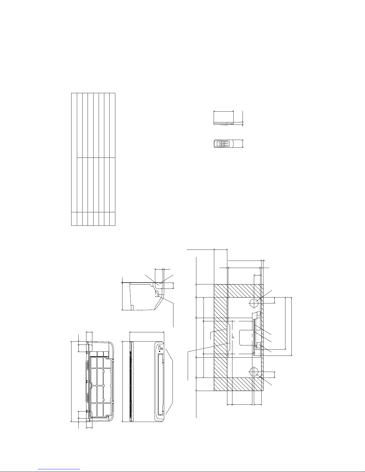
2. EXTERIOR DIMENSIONS
(1) Indoor units
Models SRK05CM, 05CM-3
SRK05CMP-3
SRK09CM-3, 09CM-4, 09CM-5
SRK09CMP-3, 09CMP-4
Note(1)Themodelnamelabelisattached
ontheundersideofthepanel.
60
150
17.3
2555
45
55
45
25
615
615
262
3210
45
609
44
56
247.1
(Servicespace)
15
7.2 7.7
44
56 40152.1
100
(Servicespace)
155.4
181.9 250 181.9
100
(Servicespace)
303 155.4
Unit
100
(Servicespace)
445.9
398.2
Installationplate
Unit:mm
Wirelessremotecontrol
Spaceforinstallationandservicewhenviewingfromthefront
Holeonwallforrightrearpiping
Holeonwallforleftrearpiping
Outletforwiring
Drainhose
Liquidpiping
F
ECD
B
Symbol
(φ65)
VP16
φ6.35(1/4")(Flare)
Content
(φ65)
Outletforpiping(onbothside)
G
Outletfordownpiping
(Refertotheaboveview)
D E AB C
Gaspiping
A
φ9.52(3/8")(Flare)
G
F
Terminalblock
-
16
-
'13•SRK-T-141
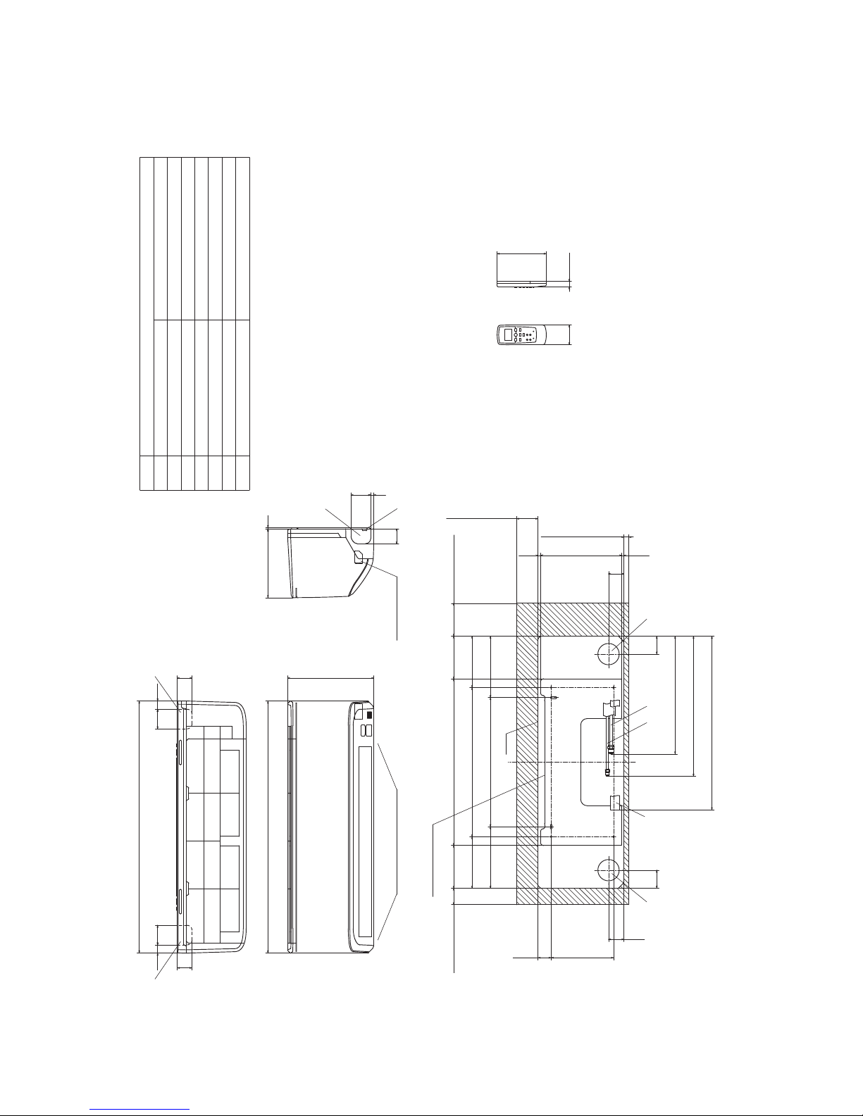
G
Terminal block
F
GG
Unit:mm
Wireless remote control
Outlet for down piping
(Refer to the above view)
Space for installation and service when viewing from the front
D E C
Hole on wall for right rear piping
Hole on wall for left rear piping
Gas piping
Outlet for wiring
Drain hose
Liquid piping
F
ECD
B
Symbol
A
(φ65)
VP16
φ6.35(1/4")(Flare)
Content
(φ65)
Outlet for piping(on both side)
G
φ12.7(1/2")(Flare)
AB
Note(1)The model name label is attached
on the underside of the indoor unit.
60
150
17.3
190 40.1
47
130.5 508 130.5
157 455 157
187.5 394 187.5
47
7.6247.5
6.9
(Service space)
65
(Service space)
15
50
(Service space)
100
(Service space)
55
409
449
530
55
Installation plate
Unit
6025 60 25
768.1
45
45
769
262
45
609
210 3
Models SRK12CM-3, 12CM-4, 12CM-5

-
17
-
'13•SRK-T-141
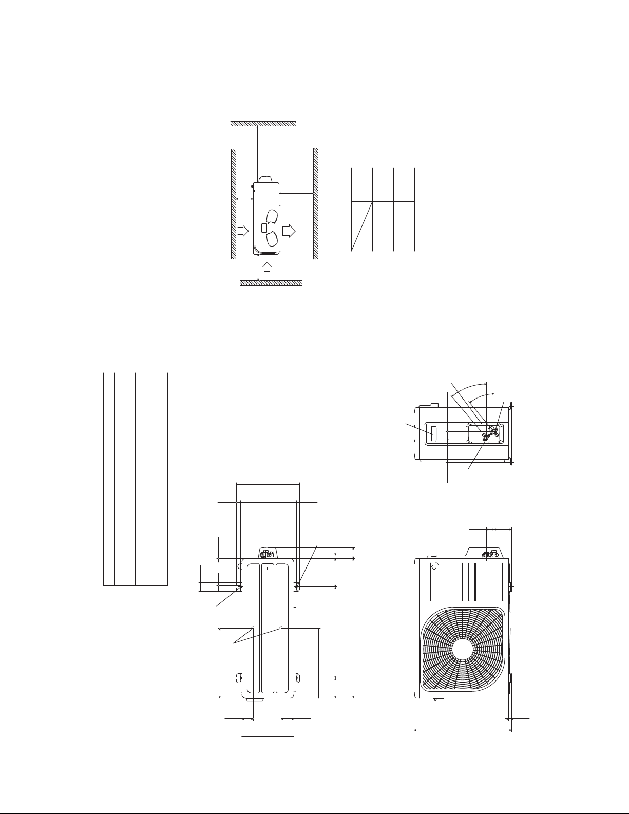
(2) Outdoor units
Models SRC05CM, 05CM-3
SRC05CMP-3
SRC09CM-3, 09CM-4, 09CM-5
SRC09CMP-3, 09CMP-4
)eralF()"8/3(25.9φ
Content
C Pipe/cable draw-out hole
D
E Anchor bolt hole
Drain discharge hole
Symbol
B
A Service valve connection(gas side)
M10×4places
φ20×2places
Service valve connection(liquid side)
)eralF()"4/1
(
53.6φ
Minimum installation space
Notes
.sedisruofllanosllawybdednuorrusebtontsumtI)1(
(2)The unit must be fixed with anchor bolts. An anchor bolt must not
protrude more than 15mm.
(3)Where the unit is subject to strong winds, lay it in such
a direction that the blower outlet faces perpendicular ly
to the dominant wind direction.
(4)Leave 1m or more space above the unit.
(5)A wall in front of the blower outlet must not exceed the unit height.
(6)The model name label is attached on the right side of the unit.
L2
L3
L4
L1 600
100
100
Examples of
Dimensions
Unit:mm
mm
installation
Outlet
Intake
L3
L1
L2
Intake
Service
space
( )
L4
Open
322
50
40
12
135
275
120.5
74.5 480 91 19.7
694.2
16.8304.414.8
336
2-16x12
Terminal block
147.2
2
0
°
2
0
°
86.3 43.2
16.5
437
E
D
BCA
-
18
-
'13•SRK-T-141
Models SRC12CM-3, 12CM-4, 12CM-5
)eralF()"4/1(53.6φ
Content
C Pipe/cable draw-out hole
D
E Anchor bolt hole
Drain discharge hole
Symbol
B
A Service valve connection(gas side)
M10×4places
φ20×2places
Service valve connection(liquid side)
)eralF()"2/1(7.21φ
L2
Intake
Outlet
Intake
L3
L1
Minimum installation space
Service
space
( )
Notes
.sedisruofllanosllawybdednuorrusebtontsumtI)1(
(2) The unit must be fixed with anchor bolts. An anchor bolt must not
protrude more than 15mm.
(3) Where the unit is subject to strong winds, lay it in such
a direction that the blower outlet faces perpendicularly
to the dominant wind direction.
(4) Leave 1m or more space above the unit.
(5) A wall in front of the blower outlet must not exceed the unit height.
(6) The model name label is attached on the right side of the unit.
L4
L2
L3
L4
L1
100
100
600
Open
Examples of
Dimensions
installation
15.8
543.8
390.6
390.6
63.469.4
290
111.6 510 158.4
780 61.9
18.9
14.8
351.6
2-16x12
312.5 24.3
50.6
12
97.7 42.5
Terminal block
40
°
4
0
°
138.4 33.5
19.9
D
E
A
C
B
Unit:mm
mm

-
19
-
'13•SRK-T-141
(3) Wireless remote control
Unit: mm
60
17.3
150
Models All model
Unit: mm
17.3
150
-
20
-
'13•SRK-T-141
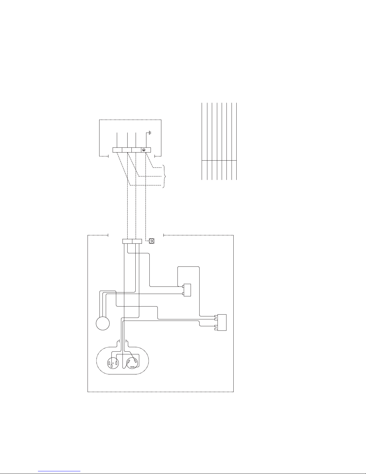
3. ELECTRICAL WIRING
(1) Indoor units
Models All model
Printed circuit board
Wireless
R-Amp
Display
CNE
WHRDBK
M
CNW
IC15
ZNR
153
CNU
CF
I
L 52C-3
52C
F
250V 3.15A
CONTROL BOX
Back up Sw
CNG
CNM
N
1〜
FM
I
T1
t°
t°
Th1
Th2
2/N
L
1
Symbol
Meaning of Marks
Parts name Symbol Parts name
Capacitor forCF
IFMI
FM
ZNR
FM
I
Fuse
Fan motor
Flap motor
Varistor
F
Th2
T1
Room temp. thermistor
Heat exchanger thermistor
Terminal block
Th1
BK
Color symbol
BL
Black
Blue
RD
WH
Red
White
BL
WH
BK
Power source
220/230/240V 50Hz
TO
OUTDOOR
UNIT
U
MFM
-
21
-
'13•SRK-T-141
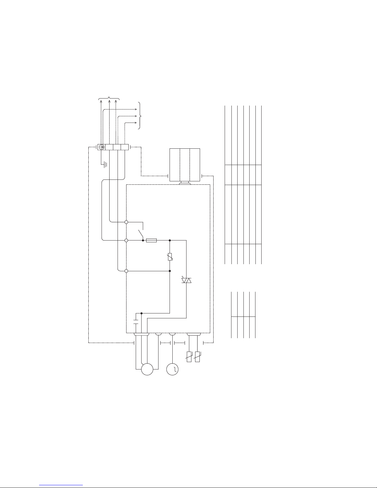
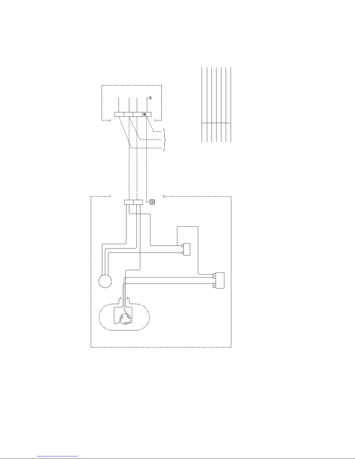
(2) Outdoor units
Models SRC05CM, 05CM-3
SRC05CMP-3
SRC09CM-3, 09CM-4, 09CM-5
SRC09CMP-3, 09CMP-4
Power source
220-240V 50Hz
INDOOR UNIT
FMo
BLACK
ORANGE
WHITE
RED
Cc
ORANGE
CFo
ORANGE
WHITE
WHITE
BLACK
BLACK
WHITE
1 2
T1
WHITE
CM
BLACK
BLACK
51C
2
3
1
RED
C
S
R
T2
WHITE
CAPACITOR
L
1
2/N
ORANGE
Symbol
Meaning of Marks
Parts name
Capacitor for CMCc
Capacitor for FMoCFo
Compressor motorCM
Fan motorFMo
Motor protector for CM51C
Terminal blockT1,T2
OUTDOOR UNIT
-
22
-
'13•SRK-T-141
Models SRC12CM-3, 12CM-4, 12CM-5
Symbol
Meaning of Marks
Parts name
Capacitor for CMCc
Capacitor for FMoCFo
Compressor motorCM
Fan motorFMo
Terminal blockT1,T2
Powersource
220-240V50Hz
INDOORUNIT
BLACK
ORANGE
WHITE
RED
Cc
ORANGE
CFo
ORANGE
WHITE
WHITE
BLACK
BLACK
WHITE
1 2
T1
WHITE
CM
BLACK
RED
C
S
R
T2
WHITE
CAPACITOR
L
1
2/N
ORANGE
OUTDOORUNIT
BLACK
FMo
-
23
-
'13•SRK-T-141
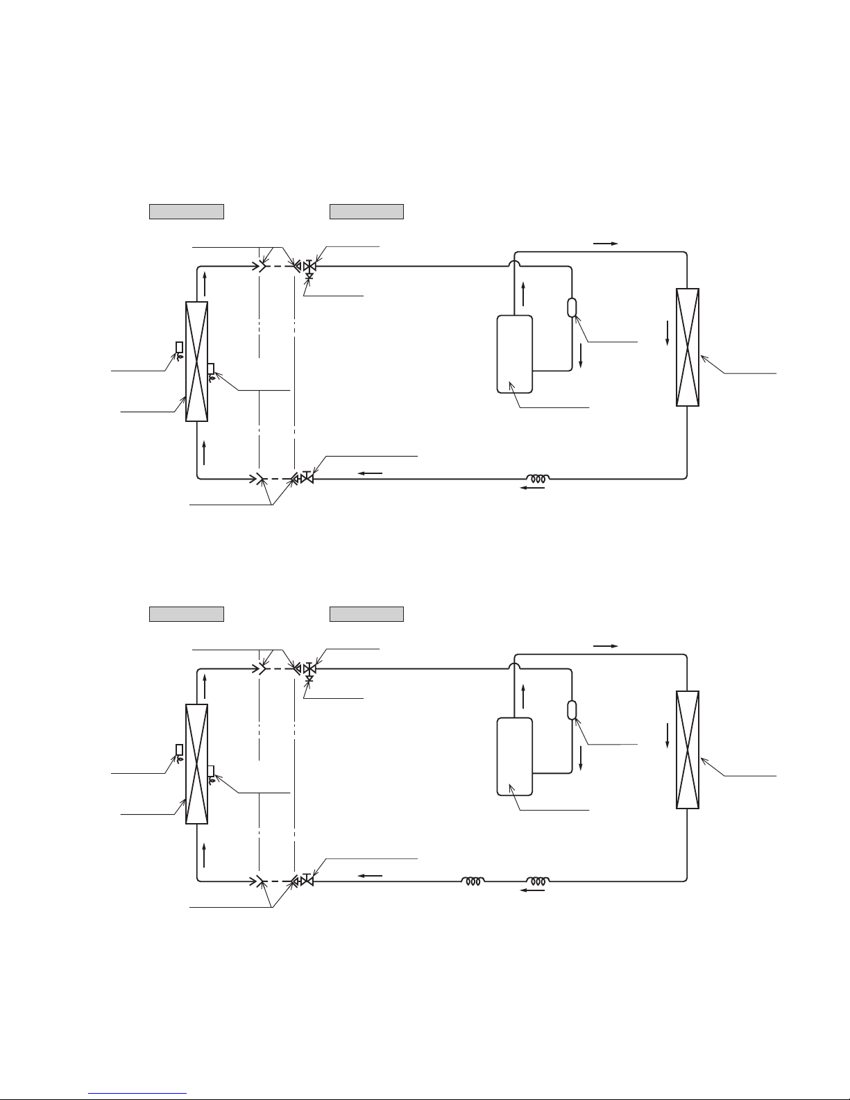
4. PIPING SYSTEM
Outdoor unitIndoor unit
Room temp.
sensor
Heat
exchanger
Flare connecting
Heat
exchanger
sensor
Piping
(Liquid)
ø6.35
Check joint
Service valve (Liquid)
Flare connecting
Heat
exchanger
Compressor
Accumulator
Service valve
(Gas)
Capillary tube
ø9.52
Piping
(Gas)
Outdoor unitIndoor unit
Room temp.
sensor
Heat
exchanger
Flare connecting
Heat
exchanger
sensor
Piping
(Liquid)
ø6.35
Check joint
Service valve (Liquid)
Flare connecting
Heat
exchanger
Compressor
Capillary tube
Accumulator
Service valve
(Gas)
Capillary tube
Piping
(Gas)
ø12.7
Models SRK05CM, 05CM-3
SRK05CMP-3
SRK09CM-3, 09CM-4, 09CM-5
SRK09CMP-3, 09CMP-4
Models SRK12CM-3, 12CM-4, 12CM-5

-
24
-
'13•SRK-T-141
5. RANGE OF USAGE & LIMITATIONS
Net capacity = Capacity shown on specification Correction factors as follows.
(1) Coefficient of cooling capacity in relation to temperatures
All model
Models
Item
Indoor return air temperature
(
Upper, lower limits
)
Outdoor air temperature
(
Upper, lower limits
)
Refer to the selection chart
Refrigerant line (one way) length
Max. 15m
Max. 5m (Outdoor unit is higher
)
Max. 5m (Outdoor unit is lower
)
Min. 3 minutes
Max. 10 times/h
Min. 85% of rating
Vertical height difference between
outdoor unit and indoor unit
Power source voltage
Voltage at starting
Frequency of ON−OFF cycle
ON and OFF interval
Rating 10%
14 16 18 20 22
15
20
25
30
35
40
0.6
0.7
0.8
0.9
1.0
1.1
1.2
1.3
43
24
ISO-T1 Standard ConditionIndoor air W.B. temperature °C W.B.
Cooling
Applicable range
Coefficient of cooling
capacity in relation
to temperature
Cooling operation
Outdoor air D.B.
temperature
°C D.B.
-
25
-
'13•SRK-T-141
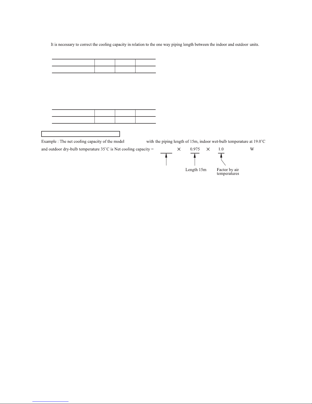
(2) Correction of cooling capacity in relation to one way length of refrigerant piping
How to obtain the cooling capacity
Model SRK05CM
=
Piping length [m]
Cooling
7.5
1.0
10
0.99 0.975
15
Models SRK05CM-3
SRK05CMP-3
SRK09CM-3, 09CM-4, 09CM-5
SRK09CMP-3, 09CMP-4
SRK12CM-3, 12CM-4, 12CM-5
Piping length [m]
Cooling
5
1.0
10
0.985 0.97
15
1500
SRK05CM
SRK05CM
1463
-
26
-
'13•SRK-T-141
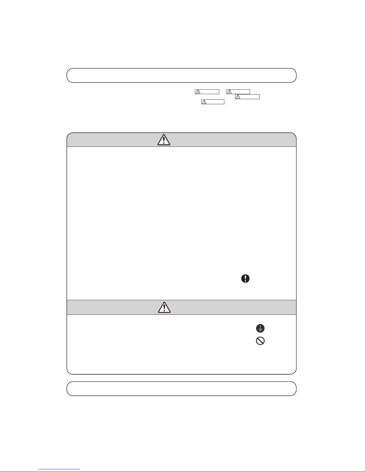
Safety precautions
• Please read these “Safety Precautions” first then accurately execute the installation work.
• Though the precautionary points indicated herein are divided under two headings,
WARNING
and
CAUTION
, those points which are related
to the strong possibility of an installation done in error resulting in death or serious injury are listed in the
WARNING
section. However, there
is also a possibility of serious consequences in relationship to the points listed in the
CAUTION
section as well. In either case, important safety
related information is indicated, so by all means, properly observe all that is mentioned.
• After completing the installation, along with confirming that no abnormalities were seen from the operation tests, please explain operating methods as
well as maintenance methods to the user (customer) of this equipment, based on the owner’s manual.
Moreover, ask the customer to keep this sheet together with the owner’s manual.
WARNING
• To disconnect the appliance from the mains supply this appliance must be connected to the mains by means of a circuit breaker or a switch (use a
recognized 10A) with a contact separation of at least 3mm.
• The appliance shall be installed in accordance with national wiring regulations.
• This systemshould be applied to placesas households, residences and thelike. Application to inferiorenvironment such as engineering shopcould
cause equipment malfunction.
• Please entrust installation to either the company which sold you the equipment or to a professional contractor. Defects from improper installations
can be the cause of water leakage, electric shocks and fires.
• Execute the installation accurately, based on following the installation manual. Again, improper installations can result in water leakage, electric
shocks and fires.
• For installation, confi rm that the installation site can suf ficiently support heavy weight. When strength is insuf fi
cient, injury can result from a
falling of the unit.
• For electrical work, please see that a licensed electrician executes the work while following the safety standards related to electrical equipment,
and local regulations as well as the installation instructions, and that only exclusive use circuits are used.
Insufficient power source circuit capacity and defective installment execution can be the cause of electric shocks and fires.
• This equipmentmust be installed with earth leakage circuit breaker (ELCB). Otherwise, it may causeelectrical shock and fire incase of equipment
breakdown.
• Accurately connect wiring using the proper cable, and insure that the external force of the cable is not conducted to the terminal connection part,
through properly securing it improper connection or securing can result in heat generation or fire.
• Take care that wiring does not rise upward, and accurately install the lid/service panel. It’s improper installation can also result heat generation or
fire.
• When setting up or moving the location of the air conditioner, do not mix air etc. or anything other than the designated refrigerant (R22) within
the refrigeration cycle.
Rupture and injury caused by abnormal high pressure can result from such mixing.
• Always use accessory parts and authorized parts for installation construction. Using parts not authorized by this company can result in water
leakage, electric shock, fire and refrigerant leakage.
• Ventilate the work area when refrigerant leaks during the operation.
Coming in contact with fire, refrigerant could generate toxic gas.
• Confirm after the foundation construction work that refrigerant does not leak.
If coming in contact with fire of a fan heater, a stove or movable cooking stove, etc., refrigerant leaking in the room could generate toxic gas.
CAUTION
• Execute proper grounding. Do not connect the ground wire to a gas pipe, water pipe, lightning rod or a telephone ground wire.
Improper placement of ground wires can result in electric shock.
• The installation of an earth leakage breaker is necessary depending on the established location of the unit.
No installing an earth leakage breaker may result in electric shock.
• Do not install the unit where there is a concern about leakage of combustible gas.
The rare even of leaked gas collecting around the unit could result in an outbreak of fire.
• For the drain pipe, follow the installation manual to insure that it allows proper drainage and thermally insulate it to prevent condensation.
Inadequate plumbing can result in water leakage and water damage to interior items.
• Install the outdoor unit so that the aluminum fins on the air heat exchanger cannot be touched. Failure to observe this may result in injury.
• Do not place objects near the outdoor unit or allow leaves to gather around the unit. If there are objects or leaves around the outdoor unit, small
animals may enter unit and contact electrical parts resulting in break down, emission of smoke or flame.
Cautions for installation
① The system should be applied to places as households, residences and the like.
② The equipment shall be installed in accordance with national wiring regulations.
③ The connection to the fixed wiring of the mains supply must be made via a double pole isolating switch with a contact gap of at least
3mm in each pole.
④ When the outdoor unit has a possibility of being overturned or being displaced and fall from its original installation position, the outdoor
unit should be fixed in its position by use of anchor bolts or wires.
6. APPLICATION DATA
Models SRK05CM, 05CM-3 SRK09CM-3, 09CM-4, 09CM-5
SRK05CMP-3 SRK09CMP-3, 09CMP-4
-
27
-
'13•SRK-T-141
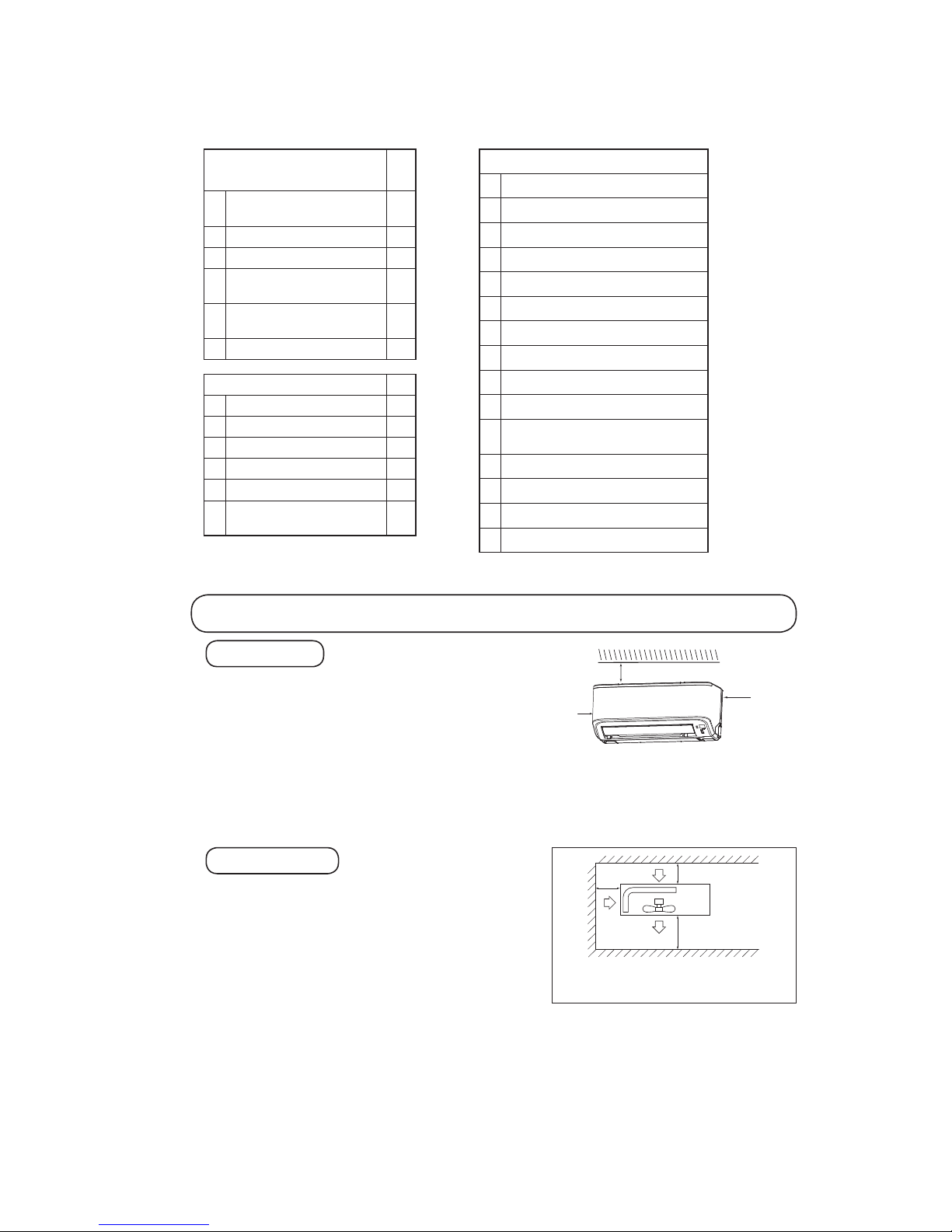
① A place where good air circulation can be obtained and where rain,
snow or sunshine will not directly strike the unit.
② A place where discharged hot air or unit’s operating sound will not be a
nuisance to the neighborhood.
③ A place where servicing space can be secured.
④ A place where vibration will not be enlarged.
*Avoid installing in the following places.
•A place near the bedroom and the like, so that the operation noise will
cause no trouble.
•A place where there is possibility of flammable gas leakage.
•A place exposed to strong wind.
•In a salt-laden atmosphere or a place where the generation of oil mist, vapor or fume is expected.
⑤ Blowing out port and suction port on the back side of the unit can be installed at a distance of 10cm from walls.
(In case the barrier is 1.2m or above in height, or is overhead, the sufficient space between the unit and wall shall be secured.)
⑥ When the unit is installed, the space of the following dimension and above shall be secured.
OUTDOOR UNIT
Selection of installation location
① Where there is no obstructions to the air flow and where the cooled
air can be evenly distributed.
② A solid place where the unit or the wall will not vibrate.
③ A place where there will be enough space for servicing. (Where
space mentioned right can be secured)
④ Where wiring and the piping work will be easy to conduct.
⑤ The place where receiving part is not exposed to the direct rays of
the sun or the strong rays of the street lighting.
⑥ A place where it can be easily drained.
⑦ A place separated at least 1m away from the television or the
radio.
(To prevent interfence to images and sounds.)
INDOOR UNIT
Standard accessories
(Installation kit)
Accessories for indoor unit
Q’ty
①
Installation board
(Attached to the rear of the indoor unit)
1
②
Wireless remote control 1
③
Remote control holder 1
④
Tapping screws
(for installation board 4dia. by 25mm)
5
⑤
Wood screw
(for remote control switch holder 3.5dia. by 16mm)
2
⑥
Battery [R03 (AAA, Micro) 1.5V]
2
Option parts Q’ty
ⓐ
Sealing plate 1
ⓑ
Sleeve 1
ⓒ
Inclination plate 1
ⓓ
Putty 1
ⓔ
Drain hose (extention hose) 1
ⓕ
Piping cover
(for insulation of connection piping)
1
Necessary tools for the installation work
1 Plus headed driver (Phillips screwdriver)
2 Knife
3 Saw
4 Tape measure
5 Hammer
6 Spanner wrench
7
Torque wrench
( )
14.0 ~ 61.0N · m
(1.4 ~ 6.1kgf · m)
8 Hole core drill (65mm in diameter)
9 Wrench key (Hexagon) [4m/m]
10 Vacuum pump
11
Vacuum pump adapter
(Anti-reverse flow type)
( )
Designed specifically
for R22
12
Gauge manifold
( )
Designed specifically
for R22
13
Charge hose
( )
Designed specifically
for R22
14
Flaring tool set
( )
Designed specifically
for R22
15
Gas leak detector
( )
Designed specifically
for R22
Note (1) If the wall is higher than 1.2 m or a ceiling is present,
distances larger thanindicated in the above table must
be provided.
Air intake
Air outlet
No obstacles
(Service space
for electrical
parts)
Air
intake
10 cm
MIN
60 cm MIN
10 cm MIN
Left
side
10 cm
10 cm
Right
side
10 cm
-
28
-
'13•SRK-T-141
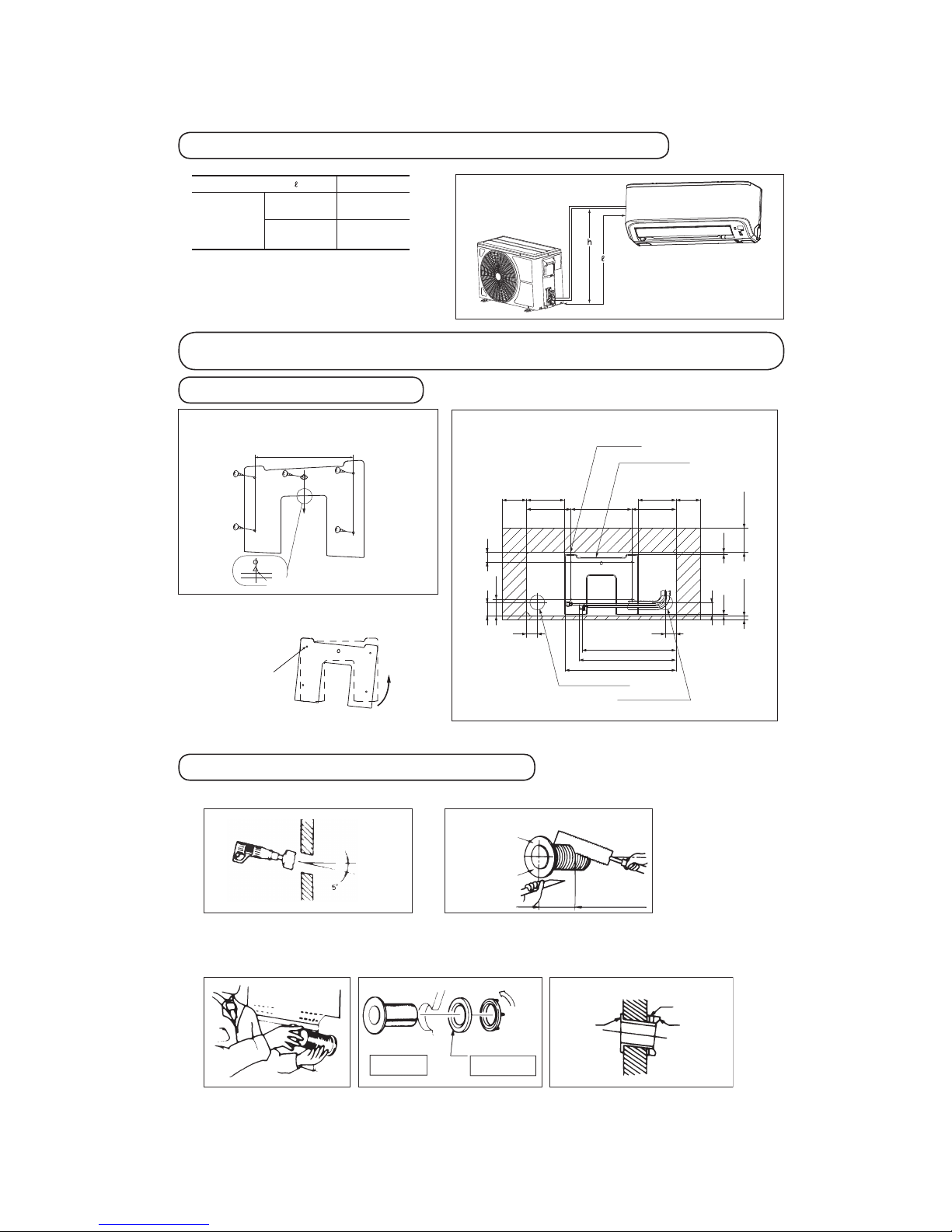
Installation of indoor unit
Installation of installation board
• Adjustment of the installation board inthe horizontal
direction is to be conducted with five screws in a
temporary tightened state.
• Adjust so that board will be level byturning the
board with the standard hole as the center.
Standard hole
Limitations for one way piping length and vertical height difference
One way piping length ( )
15 m
Vertical height
difference (h)
Outdoor
unit is lower
5 m
Outdoor
unit is higher
5 m
Look f or the inside wall structu res (Int ersediate support or
pillar and firaly install the uni t after l evel surface has be en
checked.)
Mating mark fo r level surface
250
* Leave extra space on the right side to enable removal of the lid screw.
INSTALLATION SPACE (INDOOR UNIT) (FRONT VIEW)
Unit : mm
Drilling of holes and fixture sleeve (Option parts)
Drill a hole with Ø65 whole core drill
Install the sleeve
Adjusting sleeve length
Note (1) Drill a hole with incline of 5 degree from
indoor side to outdoor side.
Wall thickness
+ 1.5 cm
Cut off the sleeve
collar that can be
seen from beneath
the unit.
Cut off the sleeve
collar in case of
drawing piping out
to rear.
Indoor side
Indoor side
Indoor side
View of sleeve when installed
Outdoor side
Outdoor side
Outdoor side
(Inserting sleeve) (*Sleeve + *Inclined + *Sealing plate)
Paste
Sleeve
Turn to
tighten
In cli ne d
flange
Seali ng
plate
Space for
service
Space for
service
Space for
service
Space for
service*
Indoor unit
181.9181.9
44
44
40
56
69.9
15
56
100
7.2 7.7
250
Installation board
Piping for Gas 398.2
Piping for Liquid 445.9
Drain hose 386.3 (
Ø16)
Piping hole (
Ø65)
Piping hole (Ø65)
100
100
155.4
155.4

-
29
-
'13•SRK-T-141
Preparation of indoor unit
① Mounting of connecting wires
ⓐ Remove the lid.
ⓑRemove the wiring clamp.
ⓒConnect the connecting wire securely to the terminal block.
Use cable for interconnection wiring to avoid loosening of the wires.
CENELEC code for cables Required field cables.
75CEI542ro)elpmaxE(5.1G4RNR50H
H Harmonized cable type
05 300/500 volts
R Natural-and/or synth. rubber wire insulation
N Polychloroprene rubber conductors insulation
R Standed core
srotcudnocforebmuN5ro4
G
One conductor of the cables is the earth conductor (yellow/green)
1.5 Section of copper wire (mm2)
• Connect the connection wire securely to the terminal block. If
the wire is not affixed completely, contact will be poor, and it
is dangerous as the terminal block may heat up and catch fire.
• Take care not to confuse the t erminal numbers for p ower
source indoor and outdoor connections.
•
Earthlead wireshall be longerthan theother lead wiresfor theelectrical
safety in case of the slipping out of the cord from the anchorage.
• The earth line of power cord must be properly earthed.
L
N
Connecting diagram.
Power supply
source
Terminal on the indoor unit
L 2/N
2
N
L
1
1
Terminal on the outdoor unit
• Affix the connection wire using the wiring clamp.
ⓓFix the connecting wire by wiring clamp.
ⓔAttach the lid.
② Shaping the pipe
③ Taping of the exterior
• Hold the bottom of the pipe and change its direction
before stretching it and shaping it.
• Tape only the portion that runs through the wall.
Always tape the crossover wires with the pipe.
④ Cautions when piping from the left and the rear center of the unit
[ Top View ]
• R emov e th e sc rew an d
pull th e drain hose, w hile
twisting.
• Re move i t wi th ha nd o r
pliers.
• I nser t th e d rai n c ap w hic h
was removed at procedure “2”
se cure ly us ing a hex ago nal
wrench etc.
Note: Be careful that if it is not
inserted securely, water leakage
may occur.
• Insert the drain hose securely,
pus h t he dr ain h ose wh ile
twisting. Install the screw.
Note: Be careful that if it is
not ins erted secure ly, water
leakage may occur.
Piping is possible in the rear,
left, left rear, l eft dow nward,
right or downward direction.
• Do not place the power supply cords above the gutter, because the
air conditioner is structuredin a way where condensation on theback
side is collected in to the drain pan before drainage.
• Do not make traps in the drain hose line.
Declining slope
Inverted slipe
Trap
* Leave space to allow
removal of this screw
after installation.
[ Drain hose changing procedures ]
Pipe
Drain hose
Terminal block
Screw*
Clamp
Lid
Left Side Piping Right Side Piping
Left rear piping
Left side piping
Right rear piping
Right side piping
Right
Left
Left rear
Rear
Downward
Left downward
1. Remove the drain hose. 2. Remove the drain cap. 3. Insert the drain cap. 4. Connect the drain hose.
Gutter
Pipes storage area
Wall

-
30
-
'13•SRK-T-141
5 Securing the indoor unit to the installation board
Wall
Indoor unit base lower latch
Installation board
Latch (2 locations)
Installation
board
Indoor unit
• How to remove the indoor unit from the installation board
1 Push up at the marked portion of the indoor unit base
lower latch, and slightly pull it toward you.
(both right and left hand sides)
(The indoor unit base lower latch can be removed from
the installation board)
2 Push up the indoor unit upward. So the indoor unit will
be removed from the installation board.
Removal and installation of the front panel
Set screws
1 Removing
• Remove the 2 set screws.
• M ove the lower part of the panel forward and push
upwards to remove. (Remove the 3 latches in the upper
section.)
2 Fitting
• Do remove the air lter.
• Cover the body with the front panel.
• Push the circled portion at the front.
• Tighten the 2 set screws.
• Fit the air lter. Carry out in the above order.
The marked portion of the
indoor unit base lower latch
Installing steps
1. Hook the upper part of
the indoor unit to the
installation board.
2. The unit can be installed
simply by gently pushing
in the lower part.

-
31
-
'13•SRK-T-141
1 2
Installation of outdoor unit
1 Make sure that the unit is stable in installation. Fix the unit to
stable base.
2 Perfrom wiring, making wire terminal numbers conform to
terminal numbers of indoor unit terminal block.
3 Earth lead wire shall be longer than the other lead wires for
the electrical safety in case of the slipping out of the cord
from the anchorage.
Terminal block
Interconnecting wire
Connection of refrigerant pipings
Preparation
Connection of refrigerant piping
Air purge
Keep the openings of the pipes covered with tapes etc. to prevent dust, sand, etc. from entering them.
• Speci ed torquing value:
Liquid side (ø6.35) : 14~18N·m (1.4~1.8kgf·m)
Gas side (ø9.52) : 34~42N·m (3.4~4.2kgf·m)
Gas side (ø12.7) : 49~61N·m (4.9~6.1kgf·m)
• Use one more spanner to x the valve.
1 Tighten all are nuts in the pipings both indoor and outside wall so as not to cause leak.
2 Connect service valve, charge hose, manifold valve and vacuum pump as is illustrated below.
3 Open manifold valve handle Lo to its full width, and perform vacuum or evacuation.
Continue the vacuum or evacuation operation for 15 minutes or more and check to see that the vacuum gauge reads – 0.1 MPa
(– 76 cmHg).
4 After completing vacuum operation, fully open service valve (Both gas and liquid sides) with hexagon headed wrench.
5 Detach the charge hoses.
6 Check for possible leakage of gas in the connection parts of both indoor and outdoor.
• Remove the ared nuts.
(on both liquid and gas sides)
• Remove the ared nuts.
(on both liquid and gas sides)
• Install the removed ared nuts to the pipes to be connected,
then are the pipes.
Dimension A
Liquid side
(ø6.35): 9.0 dia
Gas side
(ø9.52): 13.0 dia
(ø12.7): 16.2 dia
Press
Remove
Remove
(Do not
turn)
Spanner
for xing
the piping)
Torque
wrench
• Speci ed torquing value:
Liquid side (ø6.35) : 14~18N·m (1.4~1.8kgf·m)
Gas side (ø9.52) : 34~42N·m (3.4~4.2kgf·m)
Gas side (ø12.7) : 49~61N·m (4.9~6.1kgf·m)
1 Indoor unit side
2 Outdoor unit side
1 Indoor unit side 2 Outdoor unit side
• Connect rmly gas and liquid side
pipings by Torque wrench.
• Connect rmly gas and liquid side
pipings by Torque wrench.
• Always use a Torque wrench and back up spanner to tighten the are nut.
Manifol d
Valve
-76 cm Hg
Handle Lo
(pressure)
Charge hose
Stop valve
(Two-way valve)
Service port
Stop value
(Three -way
value)
Compound
(Gauge)
Pressure
gauge
Handle Hi
(pressure)
Charge hose
Vacuum pump

-
32
-
'13•SRK-T-141
When refrigerant piping exceeds 7.5m conduct additional refrigerant charge after refrigerant sweeping.
Model SRK05CM
7.5m over 15m:Additional charge amount per meter = 10g/m
[Example]
How much amount of additional charge for 15m piping?
(15 – 7.5)m × 10g/m=75g 75g for additional charge
♦ Additional refrigerant charge
When refrigerant piping exceeds 5m conduct additional refrigerant charge after refrigerant sweeping.
5m over 15m:Additional charge amount per meter = 10g/m
[Example]
How much amount of additional charge for 15m piping?
(15 – 5)m × 10g/m=100g 100g for additional charge
Installation of remote control switch
Insulation of connecting portion
Mounting method of battery
Earthing work
① Cover the connectionportion of the refrigerant piping with thepipe
cover and seal them.
If neglecting to do so, moisture occurs on thepiping and water will
drip out.
② Finishing and fixing
ⓐ Tie up the piping with wrapping tape, and shape it so that it conforms
to which the pipe is attached.
ⓑ Fix them with clamps as right figure.
Vinyl tape
To cover the connecting portion with insulation
materials, cut upper portionand then seal itwith
insulation materials.
Co ver the ext erio r p orti on wi th
covering tape and shape t he piping
so it will match the contours of t he
route tha t the pipi ng to tak e. Also
fix the wiring and pipings to the wall
with clamps.
Insulation
Refrigerant piping
Electrical wiring
Covering tape
Drain hose
Tapping screw
+
+
-
-
• Uncoverthe remote controlswitch,and mount the batteries
[R03(AAA, Micro)×2 pieces] in the body regularly.
(Fit the poles with the indication marks,+&-without
fail)
• Earth work shall be carried out without fail in order to prevent electric shock and noise generation.
• The connection of the earth cable to the following substances causes dangerous failures, therefore it shall never be done.
City water pipe, Town gas pipe, TV antenna, lightning conductor, telephone line, etc.
Trial run and operation
① Conduct trial run after confirming that there is no gas leaks.
② When conducting trial run set the remote control thermostat to continuous operation position. However when the power source is cut
off or when the unit’s operation switch is turned off or was turned to fan operation position, the unit will not go into operation in order
to protect the compressor.
③ Explain to the customer on the correct usage of the air-conditioner in simple layman’s terms.
④ Make sure that drain flows properly.
Battery
Cover
Fixing to pillar or wall
• Conventionally, operate the wireless remote control by
holding in your hand.
• Avoid installing it on a clay wall etc.
Screws
Models SRK05CM-3, 09CM-3, 09CM-4, 09CM-5
SRK05CMP-3, 09CMP-3, 09CMP-4

-
33
-
'13•SRK-T-141
Models SRK12CM-3, 12CM-4, 12CM-5
Safety precautions
• Please read these “Safety Precautions” first then accurately execute the installation work.
• Though the precautionary points indicated herein are divided under two headings,
WARNING
and
CAUTION
, those points which are related
to the strong possibility of an installation done in error resulting in death or serious injury are listed in the
WARNING
section. However, there
is also a possibility of serious consequences in relationship to the points listed in the
CAUTION
section as well. In either case, important safety
related information is indicated, so by all means, properly observe all that is mentioned.
• After completing the installation, along with confirming that no abnormalities were seen from the operation tests, please explain operating methods as
well as maintenance methods to the user (customer) of this equipment, based on the owner’s manual.
Moreover, ask the customer to keep this sheet together with the owner’s manual.
WARNING
• To disconnect the appliance from the mains supply this appliance must be connected to the mains by means of a circuit breaker or a switch (use a
recognized 15A) with a contact separation of at least 3mm.
• The appliance shall be installed in accordance with national wiring regulations.
• This systemshould be applied to placesas households, residences and the like. Application to inferiorenvironment such as engineering shopcould
cause equipment malfunction.
• Please entrust installation to either the company which sold you the equipment or to a professional contractor. Defects from improper installations
can be the cause of water leakage, electric shocks and fires.
• Execute the installation accurately, based on following the installation manual. Again, improper installations can result in water leakage, electric
shocks and fires.
• For installation, confirm that the installation site can sufficiently support heavy weight. When strength is insuf ficient, injury can result from a
falling of the unit.
• For electrical work, please see that a licensed electrician executes the work while following the safety standards related to electrical equipment,
and local regulations as well as the installation instructions, and that only exclusive use circuits are used.
Insufficient power source circuit capacity and defective installment execution can be the cause of electric shocks and fires.
• This equipmentmust be installed with earth leakage circuit breaker (ELCB). Otherwise, it may causeelectrical shock and fire incase of equipment
breakdown.
• Accurately connect wiring using the proper cable, and insure that the external force of the cable is not conducted to the terminal connection part,
through properly securing it improper connection or securing can result in heat generation or fire.
• Take care that wiring does not rise upward, and accurately install the lid/service panel. It’s improper installation can also result heat generation or
fire.
• When setting up or moving the location of the air conditioner, do not mix air etc. or anything other than the designated refrigerant (R22) within
the refrigeration cycle.
Rupture and injury caused by abnormal high pressure can result from such mixing.
• Always use accessory parts and authorized parts for installation construction. Using parts not authorized by this company can result in water
leakage, electric shock, fire and refrigerant leakage.
• Ventilate the work area when refrigerant leaks during the operation.
Coming in contact with fire, refrigerant could generate toxic gas.
• Confirm after the foundation construction work that refrigerant does not leak.
If coming in contact with fire of a fan heater, a stove or movable cooking stove, etc., refrigerant leaking in the room could generate toxic gas.
CAUTION
• Execute proper grounding. Do not connect the ground wire to a gas pipe, water pipe, lightning rod or a telephone ground wire.
Improper placement of ground wires can result in electric shock.
• The installation of an earth leakage breaker is necessary depending on the established location of the unit.
No installing an earth leakage breaker may result in electric shock.
• Do not install the unit where there is a concern about leakage of combustible gas.
The rare even of leaked gas collecting around the unit could result in an outbreak of fire.
• For the drain pipe, follow the installation manual to insure that it allows proper drainage and thermally insulate it to prevent condensation.
Inadequate plumbing can result in water leakage and water damage to interior items.
• Install the outdoor unit so that the aluminum fins on the air heat exchanger cannot be touched. Failure to observe this may result in injury.
• Do not place objects near the outdoor unit or allow leaves to gather around the unit. If there are objects or leaves around the outdoor unit, small
animals may enter unit and contact electrical parts resulting in break down, emission of smoke or flame.
Cautions for installation
① The system should be applied to places as households, residences and the like.
② The equipment shall be installed in accordance with national wiring regulations.
③ The connection to the fixed wiring of the mains supply must be made via a double pole isolating switch with a contact gap of at least
3mm in each pole.
④ When the outdoor unit has a possibility of being overturned or being displaced and fall from its original installation position, the outdoor
unit should be fixed in its position by use of anchor bolts or wires.

-
34
-
'13•SRK-T-141
① A place where good air circulation can be obtained and where rain,
snow or sunshine will not directly strike the unit.
② A place where discharged hot air or unit’s operating sound will not be a
nuisance to the neighborhood.
③ A place where servicing space can be secured.
④ A place where vibration will not be enlarged.
*Avoid installing in the following places.
•A place near the bedroom and the like, so that the operation noise will
cause no trouble.
•A place where there is possibility of flammable gas leakage.
•A place exposed to strong wind.
•In a salt-laden atmosphere or a place where the generation of oil mist, vapor or fume is expected.
⑤ Blowing out port and suction port on the back side of the unit can be installed at a distance of 10cm from walls.
(In case the barrier is 1.2m or above in height, or is overhead, the sufficient space between the unit and wall shall be secured.)
⑥ When the unit is installed, the space of the following dimension and above shall be secured.
OUTDOOR UNIT
Selection of installation location
① Where there is no obstructions to the air flow and where the cooled
air can be evenly distributed.
② A solid place where the unit or the wall will not vibrate.
③ A place where there will be enough space for servicing. (Where
space mentioned right can be secured)
④ Where wiring and the piping work will be easy to conduct.
⑤ The place where receiving part is not exposed to the direct rays of
the sun or the strong rays of the street lighting.
⑥ A place where it can be easily drained.
⑦ A place separated at least 1m away from the television or the
radio.
(To prevent interfence to images and sounds.)
INDOOR UNIT
Standard accessories
(Installation kit)
Accessories for indoor unit
Q’ty
①
Installation board
(Attached to the rear of the indoor unit)
1
②
Wireless remote control 1
③
Remote control holder 1
④
Tapping screws
(for installation board 4dia. by 25mm)
5
⑤
Wood screw
(for remote control switch holder 3.5dia. by 16mm)
2
⑥
Battery [R03 (AAA, Micro) 1.5V]
2
Option parts Q’ty
ⓐ
Sealing plate 1
ⓑ
Sleeve 1
ⓒ
Inclination plate 1
ⓓ
Putty 1
ⓔ
Drain hose (extention hose) 1
ⓕ
Piping cover
(for insulation of connection piping)
1
Necessary tools for the installation work
1 Plus headed driver (Phillips screwdriver)
2 Knife
3 Saw
4 Tape measure
5 Hammer
6 Spanner wrench
7
Torque wrench
( )
14.0 ~ 61.0N · m
(1.4 ~ 6.1kgf · m)
8 Hole core drill (65mm in diameter)
9 Wrench key (Hexagon) [4m/m]
10 Vacuum pump
11
Vacuum pump adapter
(Anti-reverse flow type)
( )
Designed specifically
for R22
12
Gauge manifold
( )
Designed specifically
for R22
13
Charge hose
( )
Designed specifically
for R22
14
Flaring tool set
( )
Designed specifically
for R22
15
Gas leak detector
( )
Designed specifically
for R22
Note (1) If the wall is higher than 1.2 m or a ceiling is present,
distances larger thanindicated in the above table must
be provided.
Air intake
Air outlet
No obstacles
(Service space
for electrical
parts)
Air
intake
10 cm
MIN
60 cm MIN
10 cm MIN
Left
side
10 cm
10 cm
Right
side
10 cm

-
35
-
'13•SRK-T-141
h
Installation of indoor unit
Installation of installation board
• Adjustment of the installation board in the horizontal
direction is to be conducted with ve screws in a
temporary tightened state.
• Adjust so that board will be level by turning the
board with the standard hole as the center.
Standard hole
Limitations for one way piping length and vertical height difference
One way piping length ( )
15 m
Vertical height
difference (h)
Outdoor
unit is lower
5 m
Outdoor
unit is higher
5 m
Look for the inside wall structures (Intersediat e support or
pillar and raly install the unit after l evel surface has b een
checked.)
Mating mark for level surfa ce
394
Drilling of holes and fi xture sleeve (Option parts)
Drill a hole with Ø65 whole core drill
Install the sleeve
Adjusting sleeve length
Note (1) Drill a hole with incline of 5 degree from
indoor side to outdoor side.
Wall thickness
+ 1.5 cm
Cut off the sleeve
collar that can be
seen from beneath
the unit.
Cut off the sleeve
collar in case of
drawing piping out
to rear.
Indoor side
Indoor side
Indoor side
View of sleeve when installed
Outdoor side
Outdoor side
Outdoor side
(Inserting sleeve) (*Sleeve + *Inclined + *Sealing plate)
Paste
Sleeve
Turn to
tighten
In cli ned
ange
Seali ng
plate
* Leave extra space on the right side to enable removal of the lid screw.
INSTALLATION SPACE (INDOOR UNIT) (FRONT VIEW)
Unit : mm
Space for
service
Space for
service
100 Space
for service
15 Space
for service*
Indoor unit
187.5 187.5394
157 157455
130.5 130.5
55
508
55
190 40.1
47
7.66.9
47
247.5
Installation board
100
50
Piping for Gas 409
Piping for Liquid 449
Drain hose 530 (
Ø16)
Piping hole (Ø65) Piping hole (Ø65)

-
36
-
'13•SRK-T-141
Preparation of indoor unit
1 Mounting of connecting wires
a Remove the lid.
b Remove the wiring clamp.
c Connect the connecting wire securely to the terminal block.
Use cable for interconnection wiring to avoid loosening of the wires.
CENELEC code for cables Required eld cables.
H05RNR4G1.5 (Example) or 245IEC57
H Harmonized cable type
05 300/500 volts
R Natural-and/or synth. rubber wire insulation
N Polychloroprene rubber conductors insulation
R Standed core
4or5 Number of conductors
G
One conductor of the cables is the earth conductor (yellow/green)
1.5 Section of copper wire (mm2)
• Connect the connection wire securely to the terminal block. If
the wire is not af xed completely, contact will be poor, and it
is dangerous as the terminal block may heat up and catch re.
• Take care not to confuse the terminal numbers for power
source indoor and outdoor connections.
•
Earth lead wire shall be longer than the other lead wires for the electrical
safety in case of the slipping out of the cord from the anchorage.
• The earth line of power cord must be properly earthed.
L
N
Connecting diagram.
Power supply
source
Terminal on the indoor unit
L 2/N
2
N
L
1
1
Terminal on the outdoor unit
• Af x the connection wire using the wiring clamp.
d Fix the connecting wire by wiring clamp.
e Attach the lid.
2 Shaping the pipe
3 Taping of the exterior
• Hold the bottom of the pipe and change its direction
before stretching it and shaping it.
• Tape only the portion that runs through the wall.
Always tape the crossover wires with the pipe.
4 Cautions when piping from the left and the rear center of the unit
[ Top View ]
• Re mov e th e s cre w an d
pull the drain hose, while
twisting.
• Remov e it with han d or
pliers.
• In ser t t he dr ain cap whi ch
was removed at procedur e “2”
se cure ly us ing a hex ago nal
wrench etc.
Note: Be careful that if it is not
inserted securely, water leakage
may occur.
• Insert the drain hose securely,
pus h t he drain h ose while
twisting. Install the screw.
Note: Be car eful that if it is
not inserted securel y, water
leakage may occur.
Piping is possible in the rear,
left, left rear, left downward,
right or downward direction.
• Do not place the power supply cords above the gutter, because the
air conditioner is structured in a way where condensation on the back
side is collected in to the drain pan before drainage.
• Do not make traps in the drain hose line.
Declining slope
Inverted slipe
Trap
* Leave space to allow
removal of this screw
after installation.
[ Drain hose changing procedures ]
Pipe
Drain hose
Terminal block
Screw*
Clamp
Lid
Left Side Piping Right Side Piping
Left rear piping
Left side piping
Right rear piping
Right side piping
Right
Left
Left rear
Rear
Downward
Left downward
1. Remove the drain hose. 2. Remove the drain cap. 3. Insert the drain cap. 4. Connect the drain hose.
Gutter
Pipes storage area
Wall

-
37
-
'13•SRK-T-141
⑤ Securing the indoor unit to the installation board
Wall
Indoor unit base lower latch
Installation board
Latch (2 locations)
Installation
board
Indoor unit
v How to remove the indoor unit from the installation board
① Push up at the marked portion of the indoor unit base
lower latch, and slightly pull it toward you.
(both right and left hand sides)
(The indoor unit base lowerlatch can be removed from
the installation board)
② Push up the indoor unitupward. So the indoor unit will
be removed from the installation board.
Removal and installation of the front panel
Set screws
① Removing
v Remove the 2 set screws.
v Move the low er par t of th e pane l for ward a nd pu sh
upwards to remove. (Remove the 3 latches in the upper
section.)
② Fitting
v Do remove the air filter.
v Cover the body with the front panel.
v Push the circled portion at the front.
v Tighten the 2 set screws.
v Fit the air filter. Carry out in the above order.
The marked portion of the
indoor unit base lower latch
Installing steps
1.Hook the upper part of
the i ndo or unit to the
installation board.
2.The unit can be installed
simply by gently pushing
in the lower part.
Latches

-
38
-
'13•SRK-T-141
Installation of outdoor unit
1 Make sure that the unit is stable in installation. Fix the unit to
stable base.
2 Perfrom wiring, making wire terminal numbers conform to
terminal numbers of indoor unit terminal block.
3 Earth lead wire shall be longer than the other lead wires for
the electrical safety in case of the slipping out of the cord
from the anchorage.
1 2
Terminal block
Interconnecting wire
Connection of refrigerant pipings
Preparation
Connection of refrigerant piping
Air purge
Keep the openings of the pipes covered with tapes etc. to prevent dust, sand, etc. from entering them.
• Speci ed torquing value:
Liquid side (ø6.35) : 14~18N·m (1.4~1.8kgf·m)
Gas side (ø9.52) : 34~42N·m (3.4~4.2kgf·m)
Gas side (ø12.7) : 49~61N·m (4.9~6.1kgf·m)
• Use one more spanner to x the valve.
1 Tighten all flare nuts in the pipings both indoor and
outside wall so as not to cause leak.
2 Connect service valve, charge hose, manifold valve and
vacuum pump as is illustrated right.
3 Open manifold valve handle Lo to its full width, and
perform vacuum or evacuation.
Con tinue the vacu um or evacua ti on oper at ion for
15 minutes or more and check to see that the vacuum
gauge reads – 0.1 MPa (– 76 cmHg).
4 After completing vacuum operation, fully open service
valve (Both gas and liquid sides) with hexagon headed
wrench.
5 Detach the charge hoses.
6 Check for possible leakage of gas in the connection parts
of both indoor and outdoor.
• Remove the ared nuts.
(on both liquid and gas sides)
• Remove the ared nuts.
(on both liquid and gas sides)
• Install the removed ared nuts to the pipes to be connected,
then are the pipes.
Dimension A
Liquid side
(ø6.35): 9.0 dia
Gas side
(ø9.52): 13.0 dia
(ø12.7): 16.2 dia
Press
Remove
Remove
(Do not
turn)
Spanner
for xing
the piping)
Torque
wrench
• Speci ed torquing value:
Liquid side (ø6.35) : 14~18N·m (1.4~1.8kgf·m)
Gas side (ø9.52) : 34~42N·m (3.4~4.2kgf·m)
Gas side (ø12.7) : 49~61N·m (4.9~6.1kgf·m)
1 Indoor unit side
2 Outdoor unit side
1 Indoor unit side 2 Outdoor unit side
• Connect rmly gas and liquid side
pipings by Torque wrench.
• Connect rmly gas and liquid side
pipings by Torque wrench.
• Always use a Torque wrench and back up spanner to tighten the are nut.
Manifol d
Valve
-76 cm Hg
Handle Lo
(pressure)
Charge hose
Stop valve
(Two-way valve)
Service port
Stop value
(Three -way
value)
Compound
(Gauge)
Pressure
gauge
Handle Hi
(pressure)
Charge hose
Vacuum pump
L
N
Connecting diagram.
Power supply
source
Terminal on the indoor unit
L 2/N
2
N
L
1
1
Terminal on the outdoor unit

-
39
-
'13•SRK-T-141
When refrigerant piping exceeds 5.0m conduct additional refrigerant charge after refrigerant sweeping.
5.0m over 15m:Additional charge amount per meter = 10g/m
[Example]
How much amount of additional charge for 15m piping?
(15 – 5.0)m × 10g/m=100g 100g for additional charge
♦ Additional refrigerant charge
Installation of wireless remote control
Insulation of connecting portion
Mounting method of battery
Earthing work
1 Cover the connection portion of the refrigerant piping with the pipe
cover and seal them.
If neglecting to do so, moisture occurs on the piping and water will
drip out.
2 Finishing and xing
a Tie up the piping with wrapping tape, and shape it so that it conforms
to which the pipe is attached.
b Fix them with clamps as right gure.
Vinyl tape
To cover the connecting portion with insulation
materials, cut upper portion and then seal it with
insulation materials.
Co ver the e xter ior po rti on w ith
covering tape and shape the piping
so it will match the con tours of the
route that the piping to take. Also
x the wiring and pipings to the wall
with clamps.
Insulation
Refrigerant piping
Electrical wiring
Covering tape
Drain hose
Tapping screw
+
+
-
-
• Uncover the wireless remote contro l, and mount the
batteri es [R03(AAA , Micro )×2 pieces] in the body
regularly.
(Fit the poles with the indication marks, + & - without
fail)
• Earth work shall be carried out without fail in order to prevent electric shock and noise generation.
• The connection of the earth cable to the following substances causes dangerous failures, therefore it shall never be done.
City water pipe, Town gas pipe, TV antenna, lightning conductor, telephone line, etc.
Trial run and operation
1 Conduct trial run after con rming that there is no gas leaks.
2 When conducting trial run set the remote control thermostat to continuous operation position. However when the power source is cut
off or when the unit’s operation switch is turned off or was turned to fan operation position, the unit will not go into operation in order
to protect the compressor.
3 Explain to the customer on the correct usage of the air-conditioner in simple layman’s terms.
4 Make sure that drain ows properly.
Battery
Cover
Fixing to pillar or wall
• Conventionally, operate the wireless remote control by
holding in your hand.
• Avoid installing it on a clay wall etc.
Screws

-
40
-
'13•SRK-T-141
Remote control
7.
OUTLINE OF OPERATION CONTROL BY MICROCOMPUTER
(1) Operation control function by remote control
◆
Operation section
Models All model
FAN SPEED button
Each time the button i s pushed, th e
indicator is switche d over in t urn.
HI POWER/ECONO button
This butt on changes the HIGH PO WER/
ECONOMY mo de.
TEMPERATURE Button
This butt on sets the room tempe rature.
(This but ton changes the presen t time and
TIMER time .)
ON TIMER button
This butt on selects ON TIMER op eration.
SLEEP button
This butt on changes to SLEEP op eration.
CLEAN switch
This swic h changes t he CLEAN mo de.
OPERATION MODE select button
Each time the button pushed, th e
indicator is switched over in turn .
ON/OFF (luminous) button
Press for starting o peration, p ress agian
for stoppi ng.
AIR FLOW (UP/DOWN) button
This butto n changes th e air flow ( up/
down) mode .
• The above illustration shows all controls, but in practi ce
only the r elevant parts a re shown.
OFF TIMER button
This butto n selects OFF TIMER o peration.
CANCEL button
This butt on cancels the ON time r, OFF
timer, and SLEEP opera tion.
RESET switch
Switch fo r resetting microcompu ter and
setting t ime.

-
41
-
'13•SRK-T-141
Models SRK05CM, 05CM-3
SRK05CMP-3
SRK09CM-3, 09CM-4, 09CM-5
SRK09CMP-3, 09CMP-4
Unit display section
ON/OFF
RUN
TIMER
RUN light (green)
TIMER light (yellow)
Illuminates during TIMER operation.
Room temperature detector
Unit ON/OFF button
This button can be used for turning on/off the unit when remote control is not available.
This button can be used for turning on/off the unit when remote control is not available.
Remote control signal receiver
Unit ON/OFF button
• Illuminates during operation.
•
Blinks at the ‘
CLEAN operation
’.
TIMER light (yellow)
Remote control signal receiver
1 sec.
ON
OFF
CLEAN operation
3 sec.
• Illuminates during operation.
•
Blinks at the ‘
CLEAN operation
’.
1 sec.
ON
OFF
CLEAN operation
3 sec.
Illuminates during TIMER operation.
RUN light (green)
Models SRK12CM-3, 12CM-4, 12CM-5

-
42
-
'13•SRK-T-141
(2) Unit ON/OFF button
When the remote control batteries become weak, or if the remote control is lost or malfunctioning, this button may be used to turn the
unit on and off.
(a) Operation
Push the button once to place the unit in the automatic mode. Push it once more to turn the unit off.
(b) Details of operation
The unit will go into the automatic mode in which it automatically determines, from room temperature (as detected by sensor),
whether to go into the cooling or thermal dry modes.
(3) Auto restart function
(a) Auto restart function records the operational status of the air-conditioner immediately prior to be switched off by a power cut,
and then automatically resumes operations after the power has been restored.
(b) The following settings will be cancelled:
(i) Timer settings
(ii) HIGH POWER operations
Notes (1) Auto restart function is set at on when the air-conditioner is shipped from the
factory. Consult with your dealer if this function needs to be switched off.
(2) When power failure ocurrs, the timer setting is cancelled. Once power is re
-
sumed, reset the timer.
(3)
If the jumper wire (J201) “AUTO RESTART” is cut, auto restart is disabled. (See
the diagram at right)
(4) Custom cord switching procedure
If two wireless remote control are installed in one room, in order to prevent wrong
operation due to mixed signals, please modify the printed circuit board in the indoor
unit’s control box and the remote control using the following procedure. Be sure to
modify both boards. If only one board is modied, receiving (and operation) cannot
be done.
(a) Modifying the indoor unit’s printed circuit board
Take out the printed circuit board from the control box and cut off jumper wire
(J200) using wire cutters.
After cutting of the jumper wire, take measures to prevent contact with the other
the lead wires, etc.
(b) Modifying the wireless remote control
(i) Remove the battery.
(ii) Cut the jumper wire shown in the gure at right.
Cut
Function
Operation mode
Room temperature
setting
Fan speed
Flap
Timer switch
COOL
About 22ºC
Auto Auto Continuous
DRY
About 23ºC
Unit ON/OFF button
Jumper wire (J201)
Jumper wire (J200)

-
43
-
'13•SRK-T-141
(5) Flap control
(a) Flap
(b) Swing
(i)
(c) Memory flap (Flap stopped)
(d) When not operating
COOL , DRY, FAN
Remote control
display
Approx. 15° Approx. 25° Approx. 35°
(Swing)
(Flap stopped)
Approx. 50° Approx. 60°
Angle of Flap from Horizontal
In COOL, DRY, FAN operation
Approx.
15°
Approx. 60°
(b) Sleep timer operation
(6) Timer operation
(a) Comfortable timer setting (ON timer)
(c) OFF timer operation

-
44
-
'13•SRK-T-141
(8) Outline of automatic operation
(a) Determination of operation mode
The unit checks the room temperature, determines the operation mode, and then begins in the automatic operation.
(7) Outline of cooling operation
(a) Operation of major functional components in Cooling mode
(b) Fan speed switching
ON OFF OFF
ON
OFF OFF
ON ON ON
Thermostat ON Thermostat OFF Failure
Cooling
Compressor
Indoor fan motor
Outdoor fan motor
Auto fan control
Speed 6
Speed 4
Speed 3
Model
Fan speed
All model
AUTO
MED
HI
LO
(b)
The unit checks the temperature every 30 minutes after the start of operation and, if the result of check is not same as the previ
-
ous operation mode, changes the operation mode.
(c)
When the unit is started again within 30 minutes after the stop of automatic operation or when the automatic operation is se
-
lected during cooling or dehumidifying operation, the unit is operated in the previous operation mode.
(d)
Setting temperature can be adjusted within the following range. There is the relationship as shown below between the signals of
the wireless remote control and the setting temperature.
Signals of wireless remote control (Display)
–6 –5 –4 –3 –2 –1
±
0 +1 +2 +3 +4 +5 +6
Setting
Cooling
16 17 18 19 20 21 22 23 24 25 26 27 28
temperature
Dehumidifying
17 18 19 20 21 22 23 24 25 26 27 28 29
Operation mode
Room temperature<26
℃
26℃≦Room temperature
Dehumidifying Cooling

-
45
-
'13•SRK-T-141
(9) Protective control function
(a) Frost prevention for indoor heat exchanger (During cooling or dehumidifying)
(i) Operating conditions
1) Indoor heat exchanger temperature (Th2) is lower than 2.5ºC.
2) 3 minutes elapsed after the start of operation.
(ii) Detail of frost prevention operation
Compressor OFF
Indoor fan Protects the fan tap just before frost prevention control.
Outdoor fan Depending on the stop mode
(iii) Reset condition: Indoor heat exchanger temperature (Th2) is higher than 15ºC.
(b) Indoor fan motor protection
When the airconditioner is operating and the indoor fan motor is turned ON, if the indoor fan motor has operated at 300 rpm or
under for more than 30 seconds, the unit enters first in the stop mode and then stops the entire system.
TIMER light illuminates simultaneously and the RUN light flashing 6-time at each 8-second.
(c) 3 minutes forced operation
When the compressor begins operating the thermal operation is not effective for 3 minutes, so operation continues as is in the
operation mode. (After 3 minutes has passed the thermal operation is effective.)
However, stopping the compressor via a stop signal or protection control has priority.
(d) Abnormality of outdoor unit
After the compressor run 5 minutes, and the indoor heat exchanger temperature more than 25ºC continuously more than 40 minutes,
then the abnormality stop occurs.
(e) Sensor disconnection (room temperature, indoor heat exchanger
)
(i) Room temperature sensor
If the temperature detected by the room temperature sensor is – 45ºC or lower, continuously for 15 seconds or longer, then
operation is stopped, an error indication is displayed. (RUN light: 2-time flash, TIMER light: ON)
(ii) Indoor heat exchanger temperature sensor
If the temperature detected by the indoor heat exchanger temperature sensor is –28º
C or lower, continuously for 15 seconds
or longer, then operation is stopped, an error indication is displayed.
(RUN light : 1-time flash, TIMER light : ON)

-
46
-
'13•SRK-T-141
8. MAINTENANCE DATA
(1) Cautions
(a) If you are disassembling and checking an air conditioner, be sure to turn off the power before beginning. When working on
indoor units, let the unit sit for about 1 minute after turning off the power before you begin work. When working on an outdoor
unit, there may be an electrical charge applied to the main circuit (electrolytic condenser), so begin work only after discharg-
ing this electrical charge (to DC 10 V or lower).
(b) When taking out printed circuit boards, be sure to do so without exerting force on the circuit boards or package components.
(c) When disconnecting and connecting connectors, take hold of the connector housing and do not pull on the lead wires.
(2) Items to check before troubleshooting
(a) Have you thoroughly investigated the details of the trouble which the customer is complaining about?
(b) Is the air conditioner running? Is it displaying any self-diagnosis information?
(c) Is a power supply with the correct voltage connected?
(d) Are the control lines connecting the indoor and outdoor units wired correctly and connected securely?
(e) Is the outdoor unit’s service valve open?
(3) Troubleshooting procedure (If the air conditioner does not run at all)
If the air conditioner does not run at all, diagnose the trouble using the following troubleshooting procedure. If the air condi-
tioner is running but breaks down, proceed to troubleshooting step (4).
Important
When all the following conditions are met, we say that the air conditioner will not run at all.
(a) The RUN light does not light up.
(b) The aps do not open.
(c) The indoor unit fan motors do not run.
(d) The self-diagnosis display does not function.
YES
YES
YES
NO
NO
NO
NO
YES
Troubleshooting procedure (If the air conditioner does not run at all)
Is the cor rec t v olt age
connected for the power
supply?
Op en man ual ly the fla p
when the power is turn off.
Do the ap close when the
power is turn on?
Is the r e a re c e pt i o n
sound emitted from the
unit when it is operated
by the remote control?
Replace the indoor PCB and
perform an operation check.
Make sure the correct voltage is connected, then perform an operation check.
Is the current fuse on the indoor unit PCB blown?
Replace PCB.
Proceed to the wireless remote
control troubleshooting procedure.
If the package components
are not damaged, replace
the fuse and perform an operation check again.
* If the voltage is correct, it will be
within the following voltage range.
AC 198 ~ 264 V

-
47
-
'13•SRK-T-141
NO
YES
(4) Troubleshooting procedure (If the air conditioner runs)
NO
NO
NO
NO
YES
YES
YES
YES
Note (1) Even in cases where only intermittent stop data are generated, the air conditioning system is normal. However, if the same protective operation recurs
repeatedly (3 or more times), it will lead to customer complaints. Judge the conditions in comparison with the contents of the complaints.
Conrm the contents of the customer complaint.
Check the self-diagnosis display.
Eliminate the cause of the trouble and perform an
operation check.
Replace the faulty component, then perform an
operation check.
Identify the faulty component by using the check
procedure corresponding to the content of the trouble.
The cause of the trouble can
be specically identied.
See below.
(5) Self-diagnosis table
When this air conditioner performs an emergency stop, the reason why the emergency stop occurred is displayed by the ashing of
display lights. If the air conditioner is operated using the remote control 3 minutes or more after the emergency stop, the trouble
display stops and the air conditioner resumes operation.
(1)
Notes (1) The air conditioner cannot be restarted using the remote control for 3 minutes after operation stops.
When a heat exchanger sensor wire disconnection is detected while operation is
stopped. (If a temperature of –28ºC or lower is detected for 15 seconds, it is
judged that the wire is disconnected.)
(Not displayed during operation.)
When a room temperature sensor wire disconnection is detected while operation
is stopped. (If a temperature of –45ºC or lower is detected for 15 seconds, it is
judged that the wire is disconnected.)
(Not displayed during operation.)
• Broken heat exchanger sensor
wire, poor connector
connection
• Indoor PCB is faulty
• Broken room temperature
sensor wire, poor connector
connection
• Indoor PCB is faulty
When conditions for turning the indoor unit’s fan motor on exist during air
conditioner operation, an indoor unit fan motor speed of 300 rpm or lower is
measured for 30 seconds or longer. (The air conditioner stops.)
• Defective fan motor, poor
connector connection
ON
1-time
flash
ON
2-time
flash
ON
6-time
flash
When there is an emergency stop caused by trouble in the outdoor unit, or the
input current value is found to be lower than the set value.
(The air conditioner stops.)
• Broken compressor wire
• Compressor blockage
•52C
relay in indoor PCB is faulty
• Improper wire connection
between indoor and outdoor
2-time
flash
ON
Indoor unit display section
Cause Display (flashing) condition
RUN
light
TIMER
light
Heat exchanger
sensor error
Room
temperature
sensor error
Indoor fan
motor error
Trouble of
outdoor unit
Description
of trouble

-
48
-
'13•SRK-T-141
(6) Inspection procedures corresponding to detail of trouble
Sensor error
[Broken sensor wire,
connector poor connection]
Is connector connection good?
YES
YES
NO
NO
Replace PCB.
Correct connection.
Replace sensor.
Is sensor resistance value good?
(Short circuit)
(Broken wire)
◆
S ensor tempe r atur e char a cteri s tics
(Room temp., indoor heat exchanger temp.)
Temperature (˚C)
Resistance (k
Ω
)
30
25
20
15
10
5
30
20
10
40 50 60
70
0
-
10
Indoor fan motor error
[Defective fan motor, connector poor
connection, defective indoor PCB]
Is connector connection good?
YES
NO
Is the output of the indoor unit
PCB normal?
Power supply reset
Correct connector connection
Is normal state restored?
Malfunction by temporary
noise
NO
Replace fan motor (If anomaly
persiste after replacing fan motor,
replace indoor PCB)
YES
Replace indoor PCB
NO

-
49
-
'13•SRK-T-141
Trouble of outdoor unit
[Compressor malfunction of
insufficient gas (refrigerant)]
Does compressor operation?
Is capacitor for compressor normal?
Replace compressor.
Insufficient gas
Is refrigerant amount normal?
Is connector for compressor connection
good?
Does trouble persist after charging gas?
Clogged capillary tube or strainer,
etc.
Replace capacitor for compressor.
Correct connection
Check if there are any places where
gas is leaking
YES
YES
NO NO
NO
NO
NO
YES
YES
YES
(7) Phenomenon observed after shortcircuit, wire breakage on sensor
(a) Indoor unit
Phenomenon
Sensor
Shortcircuit
Broken wire
Cooling
Release of continuous compressor operation command
Cooling
System can be operated normally.
Operation
mode
Continuous compressor operation command is not released.
Continuous compressor operation command is not released.
(Anti-frosting)
Heat exchanger
sensor
Room temperature
sensor

-
50
-
'13•SRK-T-141
(8) How to make sure of wireless remote control
(1)
Is remote
contro l norm al?
YES
Again pushing
operating switch
Operating the unit?
NO
Does ON/OFF button
of indoor unit operates?
Operating the unit.
NO
NO
YES
YES
Remote control
defects
Abnormality is not
found.
Replace the display
of indoor unit.
Control problem on
main unit
Is the unit
operable with remote
control?
Defective remote
control
NO
YES
Normal
Note (1) Check method of remote control
(a) Press the reset switch of the remote control.
(b) If all LCD are displayed after one (1) display, it is basically normal.

-
51
-
'13•SRK-T-141
PARTS LIST
INDOOR UNI
T
SRK05CM , SRK05CM-3
SRK05CMP-3
SRK09CM-3 , SRK09CM-4, SRK09CM-
5
SRK09CMP-3 , SRK09CMP-
4
SRK12CM-3, SRK12CM-4, SRK12CM-
5
OUTDOOR UNIT
SRC05CM , SRC05CM-3
SRC05CMP-3
SRC09CM-3 , SRC09CM-4, SRC09CM-
5
SRC09CMP-3 , SRC09CMP-
4
SRC12CM-3, SRC12CM-4, SRC12CM-
5

-
52
-
'13•SRK-T-141
CRAE0268
5
18
4
7
20
4
8
8
9
9
22
12
11
15
19
16
21
3
10
13
6
22
2
1
14
17
PANEL & FAN ASSY

-
53
-
'13•SRK-T-141
END ITEM NO. : RMA002F050A / RMA002F050AA
10 30 50 100 500 1000
1~5 RMA 102A 050 PANEL ASSY,FRONT 1 1 1 1 2
1 RMA 122A 051 PANEL,FRONT 1 1 1 2 3
2 RMA 437A 050 FILTER,AIR(TOP) 1 1 1 1 2 W605.4×D183.8(t16)
3 RMA 133A 050 PLATE,ORNAMENT 1 1 1 1 2
4 RLA 129A 017 CAP 2
5 RMA 011G 005 LABEL,WIRING 1
6~13 RMA 435A 050 GRILLE ASSY,AIR OUT 1 1 1 2 3
6 RMA 435A 051 GRILLE,AIR OUTLET 1
7 RMA 436A 050 FLAP ASSY 1
8・9 RMA 436A 052 LOUVER ASSY 2 1 1 2 2
8 RMA 129A 052 PLATE,CONNECTING 2
9 RLC 436A 002 LOUVER 6
10 SSA 512T 096 MOTOR,STEPPING 1 1 1 1 2 FOR FLAP
11 RMA 423A 001 HOSE,DRAIN 1
12 SSA 326A 047 PLUG 1
13 RMA 504A 011 HARNESS ASSY 1 1 1 1 2 FOR FLAP MOTOR
14 RMA 111A 050 BASE ASSY 1 1 1 1 2
15 RLC 129A 001 CASE,MOTOR(U) 1 1 1 1 2
16 RLC 129A 013A CASE,MOTOR(L) 1 1 1 1 2
17 SSA 923C 114 BEARING,PLANE 1 1 1 1 2
18 RMA 431G 050 IMPELLER 1 1 1 2 4
19 SSA 511T 267A MOTOR,AC 1 1 1 1 2 FOR IMPELLER
20 RMA 032A 050 PLATE,INSTALLATION 1 1 1 1 2
21 RLC 132A 001 LID 1 1 1 2 4
22 SSA 913A 007 SCREW,TAP 13 4×14
SRK05CM / SRK05CM-3
NoteNo. Part No. Part Name
RE.Q
Recommendable Purchased Q'ty

-
54
-
'13•SRK-T-141
CRAE0269
20
13
2
19
18
11
17
8
1
14
16
7
21
10
12
9
15
3
4
5
6
HEAT EXCH. & CONTROL

-
55
-
'13•SRK-T-141
END ITEM NO. : RMA002F050A / RMA002F050AA
10 30 50 100 500 1000
1~6 RMA 301A 062 HEAT EXCH ASSY(AIR) 1 1 1 1 2
2 RLC 129A 003 BRACKET(L) 1
3~5 RMA 321A 115 PIPE ASSY 1
4 SSA 323F 088 UNION(SLD) 1 FOR GAS
5 SSA 323F 088A UNION(SLD) 1 FOR LIQ.
6 RMA 129A 050 PLATE,BAFFLE 1 1 1 1 2
7 RMA 142A 051 BOX,CONTROL 1
8 SSA 551A 163F SENSOR ASSY 1 1 1 2 4
INCL.SENSOR(ROOM TEMP.& HEAT EXCH.)
9 SSA 561B 723B BLOCK,TERMINAL 1 1 1 2 2 T
10~12 RMA 505A 005 PWB ASSY 1 2 2 4 8
11 SSA 555B 058AD VARISTOR 1 1 1 1 2 Z
12 SSA 564A 132 FUSE(CURRENT) 1 1 1 2 4 F 3.15A
13 RMA 503A 001 DISPLAY ASSY 1 1 1 2 3
14 RLC 505A 003 PWB ASSY(DISPLAY) 1 2 2 4 8
15 RMA 142A 052 LID,CONTROL 1
16 RLC 129A 010 COVER,BEND 1
17 RKJ 941F 001A SPRING,LEAF 1
18 RKX 502A 001B CONTROL ASSY,REMOTE 1 2 3 5 10
19 RKN 032A 002C HOLDER(REMO-CON) 1 1 1 1 2
20 RMA 008A 013 PARTS,STANDARD 1 FOR SRK05CM
20 RMA 008A 013D PARTS,STANDARD 1 FOR SRK05CM-3
21 RMA 012A 064 MANUAL,INSTRUCTION 1 FOR SRK05CM
21 RMA 012A 065 A MANUAL,INSTRUCTION 1 FOR SRK05CM-3
(22) RMA 011F 017A LABEL,MODEL NAME 1 FOR SRK05CM
(22) RMA 011F 017AA LABEL,MODEL NAME 1 FOR SRK05CM-3
SRK05CM / SRK05CM-3
NoteNo. Part No. Part Name
RE.Q
Recommendable Purchased Q'ty

-
56
-
'13•SRK-T-141
CRAE0268
5
18
4
7
20
4
8
8
9
9
22
12
11
15
19
16
21
3
10
13
6
22
2
1
14
17
PANEL & FAN ASSY

-
57
-
'13•SRK-T-141
END ITEM NO. : RMA002F050CA
10 30 50 100 500 1000
1~5 RMA 102A 050A PANEL ASSY,FRONT 1 1 1 1 2
1 RMA 122A 051A PANEL,FRONT 1 1 1 2 3
2 RMA 437A 050A FILTER,AIR(TOP) 1 1 1 1 2
3 RMA 133A 050 PLATE,ORNAMENT 1 1 1 1 2
4 RLA 129A 017 CAP 2
5 RMA 011G 005 LABEL,WIRING 1
6~13 RMA 435A 050 GRILLE ASSY,AIR OUT 1 1 1 2 3
6 RMA 435A 051 GRILLE,AIR OUTLET 1
7 RMA 436A 050 FLAP ASSY 1
8・9 RMA 436A 052 LOUVER ASSY 2 1 1 2 2
8 RMA 129A 052 PLATE,CONNECTING 2
9 RLC 436A 002 LOUVER 6
10 SSA 512T 096 MOTOR,STEPPING 1 1 1 1 2 FOR FLAP
11 RMA 423A 001 HOSE,DRAIN 1
12 SSA 326A 047 PLUG 1
13 RMA 504A 011 HARNESS ASSY 1 1 1 1 2 FOR FLAP MOTOR
14 RMA 111A 050 BASE ASSY 1 1 1 1 2
15 RLC 129A 001 CASE,MOTOR(U) 1 1 1 1 2
16 RLC 129A 013A CASE,MOTOR(L) 1 1 1 1 2
17 SSA 923C 114 BEARING,PLANE 1 1 1 1 2
18 RMA 431G 050 IMPELLER 1 1 1 2 4
19 SSA 511T 267A MOTOR,AC 1 1 1 1 2 FOR IMPELLER
20 RMA 032A 050 PLATE,INSTALLATION 1 1 1 1 2
21 RLC 132A 001 LID 1 1 1 2 4
22 SSA 913A 007 SCREW,TAP 13 4×14
SRK05CMP-3
NoteNo. Part No. Part Name
RE.Q
Recommendable Purchased Q'ty

-
58
-
'13•SRK-T-141
CRAE0270
20
13
2
19
18
11
17
8
1
16
7
21
10
12
9
15
3
4
5
6
14
HEAT EXCH. & CONTROL

-
59
-
'13•SRK-T-141
END ITEM NO. : RMA002F050CA
10 30 50 100 500 1000
1~6 RMA 301A 060 HEAT EXCH ASSY(AIR) 1 1 1 1 2
2 RLC 129A 003 BRACKET(L) 1
3~5 RMA 321A 115 PIPE ASSY 1
4 SSA 323F 088 UNION(SLD) 1 FOR GAS
5 SSA 323F 088A UNION(SLD) 1 FOR LIQ.
6 RMA 129A 050 PLATE,BAFFLE 1 1 1 1 2
7 RMA 142A 051 BOX,CONTROL 1
8 SSA 551A 163F SENSOR ASSY 1 1 1 2 4
INCL.SENSOR(ROOM TEMP.& HEAT EXCH.)
9 SSA 561B 723B BLOCK,TERMINAL 1 1 1 2 2 T
10~12 RMA 505A 005C PWB ASSY 1 2 2 4 8
11 SSA 555B 058AD VARISTOR 1 1 1 1 2 Z
12 SSA 564A 132 FUSE(CURRENT) 1 1 1 2 4 F 3.15A
13 RMA 503A 001 DISPLAY ASSY 1 1 1 2 3
14 RLC 505A 003 PWB ASSY(DISPLAY) 1 2 2 4 8
15 RMA 142A 052 LID,CONTROL 1
16 RLC 129A 010 COVER,BEND 1
17 RKJ 941F 001A SPRING,LEAF 1
18 RKX 502A 001B CONTROL ASSY,REMOTE 1 2 3 5 10
19 RKN 032A 002C HOLDER(REMO-CON) 1 1 1 1 2
20 RMA 008A 013D PARTS,STANDARD 1
21 RMA 012A 065A MANUAL,INSTRUCTION 1
(22) RMA 011F 017CA LABEL,MODEL NAME 1
SRK05CMP-3
NoteNo. Part No. Part Name
RE.Q
Recommendable Purchased Q'ty

-
60
-
'13•SRK-T-141
CRAE0268
5
18
4
7
20
4
8
8
9
9
22
12
11
15
19
16
21
3
10
13
6
22
2
1
14
17
PANEL & FAN ASSY

-
61
-
'13•SRK-T-141
END ITEM NO. : RMA002F050BA / RMA002F050BB / RMA002F050BC
10 30 50 100 500 1000
1~5 RMA 102A 050 PANEL ASSY,FRONT 1 1 1 1 2
1 RMA 122A 051 PANEL,FRONT 1 1 1 2 3
2 RMA 437A 050 FILTER,AIR(TOP) 1 1 1 1 2 W605.4×D183.8(t16)
3 RMA 133A 050 PLATE,ORNAMENT 1 1 1 1 2
4 RLA 129A 017 CAP 2
5 RMA 011G 005 LABEL,WIRING 1
6~13 RMA 435A 050 GRILLE ASSY,AIR OUT 1 1 1 2 3
6 RMA 435A 051 GRILLE,AIR OUTLET 1
7 RMA 436A 050 FLAP ASSY 1
8・9 RMA 436A 052 LOUVER ASSY 2 1 1 2 2
8 RMA 129A 052 PLATE,CONNECTING 2
9 RLC 436A 002 LOUVER 6
10 SSA 512T 096 MOTOR,STEPPING 1 1 1 1 2 FOR FLAP
11 RMA 423A 001 HOSE,DRAIN 1
12 SSA 326A 047 PLUG 1
13 RMA 504A 011 HARNESS ASSY 1 1 1 1 2 FOR FLAP MOTOR
14 RMA 111A 050 BASE ASSY 1 1 1 1 2
15 RLC 129A 001 CASE,MOTOR(U) 1 1 1 1 2
16 RLC 129A 013A CASE,MOTOR(L) 1 1 1 1 2
17 SSA 923C 114 BEARING,PLANE 1 1 1 1 2
18 RMA 431G 050 IMPELLER 1 1 1 2 4
19 SSA 511T 267A MOTOR,AC 1 1 1 1 2 FOR IMPELLER
20 RMA 032A 050 PLATE,INSTALLATION 1 1 1 1 2
21 RLC 132A 001 LID 1 1 1 2 4
22 SSA 913A 007 SCREW,TAP 13 4×14
SRK09CM-3 / SRK09CM-4 / SRK09CM-5
NoteNo. Part No. Part Name
RE.Q
Recommendable Purchased Q'ty

-
62
-
'13•SRK-T-141
CRAE0271
22
15
4
21
20
13
19
10
1
3
2
18
9
23
12
14
11
17
5
6
7
8
16
HEAT EXCH. & CONTROL

-
63
-
'13•SRK-T-141
END ITEM NO. : RMA002F050BA / RMA002F050BB / RMA002F050BC
10 30 50 100 500 1000
1~8 RMA 301A 058 HEAT EXCH ASSY(AIR) 1 1 1 1 2
2 RMA 315D 050 HEADER ASSY 1
3 RMA 315A 050 DISTRIBUTOR ASSY 1
4 RLC 129A 003 BRACKET(L) 1
5~7 RMA 321A 091 PIPE ASSY 1
6 SSA 323F 088 UNION(SLD) 1 FOR GAS
7 SSA 323F 088A UNION(SLD) 1 FOR LIQ.
8 RMA 129A 050 PLATE,BAFFLE 1 1 1 1 2
9 RMA 142A 051 BOX,CONTROL 1
10 SSA 551A 163F SENSOR ASSY 1 1 1 2 4
INCL.SENSOR(ROOM TEMP.& HEAT EXCH.)
11 SSA 561B 723B BLOCK,TERMINAL 1 1 1 2 2 T
12~14 RMA 505A 005A PWB ASSY 1 2 2 4 8
13 SSA 555B 058AD VARISTOR 1 1 1 1 2 Z
14 SSA 564A 132 FUSE(CURRENT) 1 1 1 2 4 F 3.15A
15 RMA 503A 001 DISPLAY ASSY 1 1 1 2 3
16 RLC 505A 003 PWB ASSY(DISPLAY) 1 2 2 4 8
17 RMA 142A 052 LID,CONTROL 1
18 RLC 129A 010 COVER,BEND 1
19 RKJ 941F 001A SPRING,LEAF 1
20 RKX 502A 001B CONTROL ASSY,REMOTE 1 2 3 5 10
21 RKN 032A 002C HOLDER(REMO-CON) 1 1 1 1 2
22 RMA 008A 013D PARTS,STANDARD 1 FOR SRK09CM-3
22 RMA 008A 013F PARTS,STANDARD 1 FOR SRK09CM-4
22 RMA 008A 013G PARTS,STANDARD 1 FOR SRK09CM-5
23 RMA 012A 065A MANUAL,INSTRUCTION 1 FOR SRK09CM-3
23 RMA 012A 066A MANUAL,INSTRUCTION 1 FOR SRK09CM-4
23 RMA 012A 067A MANUAL,INSTRUCTION 1 FOR SRK09CM-5
(24) RMA 011F 017BA LABEL,MODEL NAME 1 FOR SRK09CM-3
(24) RMA 011F 017BB LABEL,MODEL NAME 1 FOR SRK09CM-4
(24) RMA 011F 017BC LABEL,MODEL NAME 1 FOR SRK09CM-5
SRK09CM-3 / SRK09CM-4 / SRK09CM-5
NoteNo. Part No. Part Name
RE.Q
Recommendable Purchased Q'ty

-
64
-
'13•SRK-T-141
CRAE0268
5
18
4
7
20
4
8
8
9
9
22
12
11
15
19
16
21
3
10
13
6
22
2
1
14
17
PANEL & FAN ASSY

-
65
-
'13•SRK-T-141
END ITEM NO. : RMA002F050DA / RMA002F050DB
10 30 50 100 500 1000
1~5 RMA 102A 050A PANEL ASSY,FRONT 1 1 1 1 2
1 RMA 122A 051A PANEL,FRONT 1 1 1 2 3
2 RMA 437A 050A FILTER,AIR(TOP) 1 1 1 1 2
3 RMA 133A 050 PLATE,ORNAMENT 1 1 1 1 2
4 RLA 129A 017 CAP 2
5 RMA 011G 005 LABEL,WIRING 1
6~13 RMA 435A 050 GRILLE ASSY,AIR OUT 1 1 1 2 3
6 RMA 435A 051 GRILLE,AIR OUTLET 1
7 RMA 436A 050 FLAP ASSY 1
8・9 RMA 436A 052 LOUVER ASSY 2 1 1 2 2
8 RMA 129A 052 PLATE,CONNECTING 2
9 RLC 436A 002 LOUVER 6
10 SSA 512T 096 MOTOR,STEPPING 1 1 1 1 2 FOR FLAP
11 RMA 423A 001 HOSE,DRAIN 1
12 SSA 326A 047 PLUG 1
13 RMA 504A 011 HARNESS ASSY 1 1 1 1 2 FOR FLAP MOTOR
14 RMA 111A 050 BASE ASSY 1 1 1 1 2
15 RLC 129A 001 CASE,MOTOR(U) 1 1 1 1 2
16 RLC 129A 013A CASE,MOTOR(L) 1 1 1 1 2
17 SSA 923C 114 BEARING,PLANE 1 1 1 1 2
18 RMA 431G 050 IMPELLER 1 1 1 2 4
19 SSA 511T 267A MOTOR,AC 1 1 1 1 2 FOR IMPELLER
20 RMA 032A 050 PLATE,INSTALLATION 1 1 1 1 2
21 RLC 132A 001 LID 1 1 1 2 4
22 SSA 913A 007 SCREW,TAP 13 4×14
SRK09CMP-3 / SRK09CMP-4
NoteNo. Part No. Part Name
RE.Q
Recommendable Purchased Q'ty

-
66
-
'13•SRK-T-141
CRAE0270
20
13
2
19
18
11
17
8
1
16
7
21
10
12
9
15
3
4
5
6
14
HEAT EXCH. & CONTROL

-
67
-
'13•SRK-T-141
END ITEM NO. : RMA002F050DA / RMA002F050DB
10 30 50 100 500 1000
1~6 RMA 301A 060 HEAT EXCH ASSY(AIR) 1 1 1 1 2
2 RLC 129A 003 BRACKET(L) 1
3~5 RMA 321A 115 PIPE ASSY 1
4 SSA 323F 088 UNION(SLD) 1 FOR GAS
5 SSA 323F 088A UNION(SLD) 1 FOR LIQ.
6 RMA 129A 050 PLATE,BAFFLE 1 1 1 1 2
7 RMA 142A 051 BOX,CONTROL 1
8 SSA 551A 163F SENSOR ASSY 1 1 1 2 4
INCL.SENSOR(ROOM TEMP.& HEAT EXCH.)
9 SSA 561B 723B BLOCK,TERMINAL 1 1 1 2 2 T
10~12 RMA 505A 005D PWB ASSY 1 2 2 4 8
11 SSA 555B 058AD VARISTOR 1 1 1 1 2 Z
12 SSA 564A 132 FUSE(CURRENT) 1 1 1 2 4 F 3.15A
13 RMA 503A 001 DISPLAY ASSY 1 1 1 2 3
14 RLC 505A 003 PWB ASSY(DISPLAY) 1 2 2 4 8
15 RMA 142A 052 LID,CONTROL 1
16 RLC 129A 010 COVER,BEND 1
17 RKJ 941F 001A SPRING,LEAF 1
18 RKX 502A 001B CONTROL ASSY,REMOTE 1 2 3 5 10
19 RKN 032A 002C HOLDER(REMO-CON) 1 1 1 1 2
20 RMA 008A 013D PARTS,STANDARD 1 FOR SRK09CMP-3
20 RMA 008A 013F PARTS,STANDARD 1 FOR SRK09CMP-4
21 RMA 012A 065A MANUAL,INSTRUCTION 1 FOR SRK09CMP-3
21 RMA 012A 066A MANUAL,INSTRUCTION 1 FOR SRK09CMP-4
(22) RMA 011F 017DA LABEL,MODEL NAME 1 FOR SRK09CMP-3
(22) RMA 011F 017DB LABEL,MODEL NAME 1 FOR SRK09CMP-4
SRK09CMP-3 / SRK09CMP-4
NoteNo. Part No. Part Name
RE.Q
Recommendable Purchased Q'ty

-
68
-
'13•SRK-T-141
CRAE0272
1
18
3
4
7
20
4
8
8
9
9
22
12
10
11
15
19
16
21
6
22
2
14
17
5
13
PANEL & FAN ASSY

-
69
-
'13•SRK-T-141
END ITEM NO. : RMA002F051A / RMA002F051AA / RMA002F051AB
10 30 50 100 500 1000
1~5 RMA 102A 051 PANEL ASSY,FRONT 1 1 1 1 2
1 RMA 122A 052 PANEL,FRONT 1 1 1 2 3
2 RLC 437A 001 FILTER,AIR(TOP) 1 1 1 1 2 W623×H183(t14)
3 RLC 133A 002 PLATE,ORNAMENT 1 1 1 1 2
4 RLA 129A 017 CAP 2
5 RMA 011G 005 LABEL,WIRING 1
6~13 RLC 435A 001A GRILLE ASSY,AIR OUT 1 1 1 2 3
6 RLC 435A 002 GRILLE,AIR OUTLET 1
7 RLC 436A 003 FLAP ASSY 1
8・9 RLC 436A 004 LOUVER ASSY 2 1 1 2 2
8 RLC 129A 009 PLATE,CONNECTING 2
9 RLC 436A 002 LOUVER 10
10 SSA 512T 096 MOTOR,STEPPING 1 1 1 1 2 FOR FLAP
11 SSA 423A 102 HOSE,DRAIN 1
12 SSA 326A 047 PLUG 1
13 RMA 504A 011 HARNESS ASSY 1 1 1 1 2 FOR FLAP MOTOR
14 RLC 111A 001 BASE ASSY 1 1 1 1 2
15 RLC 129A 012 CASE,ASSY(U) 1 1 1 1 2
16 RLC 129A 013 CASE,ASSY(L) 1 1 1 1 2
17 SSA 923C 114 BEARING,PLANE 1 1 1 1 2
18 SSA 431G 051 IMPELLER 1 1 1 2 4
19 SSA 511T 267 MOTOR,AC 1 1 1 1 2 FOR IMPELLER
20 RLC 032A 001 PLATE,INSTALLATION 1 1 1 1 2
21 RLC 132A 001 LID 1 1 1 2 4
22 SSA 913A 007 SCREW,TAP 16 4×14
SRK12CM-3 / SRK12CM-4 / SRK12CM-5
NoteNo. Part No. Part Name
RE.Q
Recommendable Purchased Q'ty

-
70
-
'13•SRK-T-141
CRAE0273
22
15
4
23
21
20
14
13
17
2
10
3
1
16
19
9
12
18
11
5
6
7
8
HEAT EXCH. & CONTROL

-
71
-
'13•SRK-T-141
END ITEM NO. : RMA002F051A / RMA002F051AA / RMA002F051AB
10 30 50 100 500 1000
1~8 RMA 301A 056 HEAT EXCH ASSY(AIR) 1 1 1 1 2
2 RMA 315D 051 HEADER ASSY 1
3 RMA 315A 051 DISTRIBUTOR ASSY 1
4 RLC 129A 003 BRACKET(L) 1
5~7 RMA 321A 122 PIPE ASSY 1
6 SSA 323F 088B UNION(SLD) 1 FOR GAS
7 SSA 323F 088A UNION(SLD) 1 FOR LIQ.
8 RLC 129A 004 PLATE,BAFFLE 1 1 1 1 2
9 RLC 142A 001 BOX,CONTROL 1
10 SSA 551A 163F SENSOR ASSY 1 1 1 2 4
INCL.SENSOR(ROOM TEMP.& HEAT EXCH.)
11 SSA 561B 723B BLOCK,TERMINAL 1 1 1 2 2 T
12~14 RMA 505A 005B PWB ASSY 1 2 2 4 8
13 SSA 555B 058AD VARISTOR 1 1 1 1 2 Z
14 SSA 564A 132 FUSE(CURRENT) 1 1 1 2 4 F 3.15A
15 RMA 503A 002 DISPLAY ASSY 1 1 1 2 3
16 RLC 505A 003 PWB ASSY(DISPLAY) 1 2 2 4 8
17 RKJ 941F 001A SPRING,LEAF 1
18 RLC 142A 002 LID,CONTROL 1
19 RLC 129A 010 COVER,BEND 1
20 RKX 502A 001P CONTROL ASSY,REMOTE 1 2 3 5 10
21 RKN 032A 002C HOLDER(REMO-CON) 1 1 1 1 2
22 RMA 008A 014 PARTS,STANDARD 1 FOR SRK12CM-3
22 RMA 008A 014A PARTS,STANDARD 1 FOR SRK12CM-4
22 RMA 008A 014B PARTS,STANDARD 1 FOR SRK12CM-5
23 RMA 012A 068 MANUAL,INSTRUCTION 1 FOR SRK12CM-3
23 RMA 012A 069 MANUAL,INSTRUCTION 1 FOR SRK12CM-4
23 RMA 012A 070 MANUAL,INSTRUCTION 1 FOR SRK12CM-5
(24) RMA 011F 017FA LABEL,MODEL NAME 1 FOR SRK12CM-3
(24) RMA 011F 017FB LABEL,MODEL NAME 1 FOR SRK12CM-4
(24) RMA 011F 017FC LABEL,MODEL NAME 1 FOR SRK12CM-5
SRK12CM-3 / SRK12CM-4 / SRK12CM-5
NoteNo. Part No. Part Name
RE.Q
Recommendable Purchased Q'ty

-
72
-
'13•SRK-T-141
CRBE0358
7
4
12
6
1
14
15
7
6
5
8
3
6
9
6
13
11
10
2
PANEL & FAN ASSY

-
73
-
'13•SRK-T-141
END ITEM NO. : RMC003F050A
10 30 50 100 500 1000
1 RMC 122A 051 PANEL,FRONT 1 1 1 1 2
2 RMC 124A 050 PANEL ASSY,TOP 1 1 1 1 2
3 RMC 123A 053 PANEL ASSY,SIDE(R) 1 1 1 1 2
4 RMC 435A 050 GRILLE,AIR OUTLET 1 1 1 2 3
5 SSA 944B 036B HANDLE 1
6 SSA 913A 034F SCREW,TAP 22 4×8
7 SSA 913A 034G SCREW,TAP 6 4×12
8 SSA 913A 035 SCREW,TAP 1 5×10
9 RMC 132A 050 COVER,SERVICE 1
10 RMC 116A 050 BRACKET,MOTOR 1
11 SSA 511B 074 MOTOR,AC 1 2 2 4 8
12 RMC 141A 051 PLATE ASSY,BAFFLE 1
13 SSA 431B 168 PROPELLER 1 1 1 2 4
14
SSA 914B 007AD NUT,TH
1
15 RCW 111A 003A BASE ASSY
1
1 1 1 2
SRC05CM
NoteNo. Part No. Part Name
RE.Q
Recommendable Purchased Q'ty

-
74
-
'13•SRK-T-141
CRBE0359
1
2
4
7
13
12
11
19
10
14
17
15
8
9
18
16
5
(LIQ.)
(GAS)
3
6
HEAT EXCH. & CONTROL

-
75
-
'13•SRK-T-141
END ITEM NO. : RMC003F050A
10 30 50 100 500 1000
1 RMC 301A 055 HEAT EXCH ASSY(AIR) 1 1 1 1 2
2・3 RMC 304A 029A PIPING ASSY(EXPAN) 1
3 RMC 315B 027 CAPILLARY 1 ij1.2×ij2.5 L700
4 RCW 116A 002 BRACKET(VALVE) 1
5 RMC 381A 050 VALVE,SERVICE(1/4") 1 1 1 1 2 LIQ.
6 RMC 381A 051 VALVE,SERVICE(3/8") 1 1 1 1 2 GAS
7 RCK 154D 507 INSULATION,COMP 1
8 RMC 201A 009 COMPRESSOR ASSY 1 1 2 3 8
9 RMC 941C 050 CUSHION,RUBBER 3
10 SSA 914C 013A NUT,FLANGE 3
11 RMC 932C 002 GASKET,COVER 1
12 RMC 947K 002 COVER,TERMINAL 1 1 1 2 4
13 SSA 914C 016 NUT,FLANGE 1
14 SSA 552A 842A CAPACITOR,RUNNING 1 1 1 1 2 CFO 2.5µF 450VAC
15 SSA 552A 843 CAPACITOR,RUNNING 1 1 1 1 2 CC 20µF 400VAC
16 RMC 533B 005 PROTECTOR,MOTOR 1 1 1 1 2
17 SSA 561B 669 BLOCK,TERMINAL 1 1 1 2 2
18 RMC 504A 010A WIRING ASSY 1 FOR CPMP.
19 RMC 011G 009 LABEL,WIRING 1
(20) RMC 011F 019A LABEL,MODEL NAME 1
SRC05CM
NoteNo. Part No. Part Name
RE.Q
Recommendable Purchased Q'ty

-
76
-
'13•SRK-T-141
CRBE0358
7
4
12
6
1
14
15
7
6
5
8
3
6
9
6
13
11
10
2
PANEL & FAN ASSY

-
77
-
'13•SRK-T-141
END ITEM NO. : RMC003F050AA
10 30 50 100 500 1000
1 RMC 122A 051 PANEL,FRONT 1 1 1 1 2
2 RMC 124A 050 PANEL ASSY,TOP 1 1 1 1 2
3 RMC 123A 053 PANEL ASSY,SIDE(R) 1 1 1 1 2
4 RMC 435A 050 GRILLE,AIR OUTLET 1 1 1 2 3
5 SSA 944B 036B HANDLE 1
6 SSA 913A 034F SCREW,TAP 24 4×8
7 SSA 913A 034G SCREW,TAP 6 4×12
8 SSA 913A 035 SCREW,TAP 1 5×10
9 RMC 132A 050 COVER,SERVICE 1
10 RMC 116A 050A BRACKET,MOTOR 1
11 SSA 511B 074 MOTOR,AC 1 2 2 4 8
12 RMC 141A 051 PLATE ASSY,BAFFLE 1
13 SSA 431B 168 PROPELLER 1 1 1 2 4
14
SSA 914B 007AD NUT,TH
1
15 RCW 111A 003A BASE ASSY
1
1 1 1 2
SRC05CM-3
NoteNo. Part No. Part Name
RE.Q
Recommendable Purchased Q'ty

-
78
-
'13•SRK-T-141
CRBE0360
2
1
3
5
8
14
13
12
20
11
15
18
16
9
10
19
17
6
(LIQ.)
(GAS)
4
7
HEAT EXCH. & CONTROL

-
79
-
'13•SRK-T-141
END ITEM NO. : RMC003F050AA
10 30 50 100 500 1000
1 RMC 301A 063 HEAT EXCH ASSY(AIR) 1 1 1 1 2
2 RMC 301A 060 HEAT EXCH ASSY(AIR) 1 1 1 1 2
3・4 RMC 304A 034 PIPING ASSY(EXPAN) 1
4 RMC 315B 029 CAPILLARY 1 ij1.2×ij2.5 L750
5 RCW 116A 002 BRACKET(VALVE) 1
6 RMC 381A 050 VALVE,SERVICE(1/4") 1 1 1 1 2 LIQ.
7 RMC 381A 051 VALVE,SERVICE(3/8") 1 1 1 1 2 GAS
8 RCK 154D 507 INSULATION,COMP 1
9 RMC 201A 055 COMPRESSOR ASSY 1 1 2 3 8
10 RMC 941C 050 CUSHION,RUBBER 3
11 SSA 914C 013A NUT,FLANGE 3
12 RMC 932C 002 GASKET,COVER 1
13 RMC 947K 002 COVER,TERMINAL 1 1 1 2 4
14 SSA 914C 016 NUT,FLANGE 1
15 SSA 552A 842A CAPACITOR,RUNNING 1 1 1 1 2 CFO 2.5µF 450VAC
16 SSA 552A 843 CAPACITOR,RUNNING 1 1 1 1 2 CC 20µF 400VAC
17 RMC 533B 005 PROTECTOR,MOTOR 1 1 1 1 2
18 SSA 561B 669 BLOCK,TERMINAL 1 1 1 2 2
19 RMC 504A 010A WIRING ASSY 1 FOR CPMP.
20 RMC 011G 009 LABEL,WIRING 1
(21) RMC 011F 019AA LABEL,MODEL NAME 1
SRC05CM-3
NoteNo. Part No. Part Name
RE.Q
Recommendable Purchased Q'ty

-
80
-
'13•SRK-T-141
CRBE0361
7
4
12
6
1
14
15
7
6
5
8
3
6
9
6
13
11
10
2
PANEL & FAN ASSY

-
81
-
'13•SRK-T-141
END ITEM NO. : RMC003F050CA
10 30 50 100 500 1000
1 RMC 122A 051A PANEL,FRONT 1 1 1 1 2
2 RMC 124A 050 PANEL ASSY,TOP 1 1 1 1 2
3 RMC 123A 053 PANEL ASSY,SIDE(R) 1 1 1 1 2
4 RMC 435A 050 GRILLE,AIR OUTLET 1 1 1 2 3
5 SSA 944B 036B HANDLE 1
6 SSA 913A 034F SCREW,TAP 22 4×8
7 SSA 913A 034G SCREW,TAP 6 4×12
8 SSA 913A 035 SCREW,TAP 1 5×10
9 RMC 132A 050 COVER,SERVICE 1
10 RMC 116A 050 BRACKET,MOTOR 1
11 SSA 511B 074 MOTOR,AC 1 2 2 4 8
12 RMC 141A 051 PLATE ASSY,BAFFLE 1
13 SSA 431B 168 PROPELLER 1 1 1 2 4
14
SSA 914B 007AD NUT,TH
1
15 RCW 111A 003A BASE ASSY
1
1 1 1 2
SRC05CMP-3
NoteNo. Part No. Part Name
RE.Q
Recommendable Purchased Q'ty

-
82
-
'13•SRK-T-141
CRBE0362
1
2
4
7
13
12
11
19
10
14
17
15
8
9
18
16
5
(LIQ.)
(GAS)
3
6
HEAT EXCH. & CONTROL

-
83
-
'13•SRK-T-141
END ITEM NO. : RMC003F050CA
10 30 50 100 500 1000
1 RMC 301A 050 HEAT EXCH ASSY(AIR) 1 1 1 1 2
2・3 RMC 304A 029 PIPING ASSY(EXPAN) 1
3 RMC 315B 026 CAPILLARY 1 ij1.2×ij2.5 L600
4 RCW 116A 002 BRACKET(VALVE) 1
5 RMC 381A 050 VALVE,SERVICE(1/4") 1 1 1 1 2 LIQ.
6 RMC 381A 051 VALVE,SERVICE(3/8") 1 1 1 1 2 GAS
7 RCK 154D 507 INSULATION,COMP 1
8 RMC 201A 009 COMPRESSOR ASSY 1 1 2 3 8
9 RMC 941C 050 CUSHION,RUBBER 3
10 SSA 914C 013A NUT,FLANGE 3
11 RMC 932C 002 GASKET,COVER 1
12 RMC 947K 002 COVER,TERMINAL 1 1 1 2 4
13 SSA 914C 016 NUT,FLANGE 1
14 SSA 552A 842A CAPACITOR,RUNNING 1 1 1 1 2 CFO 2.5µF 450VAC
15 SSA 552A 843 CAPACITOR,RUNNING 1 1 1 1 2 CC 20µF 400VAC
16 RMC 533B 005 PROTECTOR,MOTOR 1 1 1 1 2
17 SSA 561B 669 BLOCK,TERMINAL 1 1 1 2 2
18 RMC 504A 010A WIRING ASSY 1 FOR CPMP.
19 RMC 011G 009 LABEL,WIRING 1
(20) RMC 011F 019CA LABEL,MODEL NAME 1
SRC05CMP-3
NoteNo. Part No. Part Name
RE.Q
Recommendable Purchased Q'ty

-
84
-
'13•SRK-T-141
CRBE0358
7
4
12
6
1
14
15
7
6
5
8
3
6
9
6
13
11
10
2
PANEL & FAN ASSY

-
85
-
'13•SRK-T-141
END ITEM NO. : RMC003F050BA / RMC003F050BB / RMC003F050BC
10 30 50 100 500 1000
1 RMC 122A 051 PANEL,FRONT 1 1 1 1 2
2 RMC 124A 050 PANEL ASSY,TOP 1 1 1 1 2
3 RMC 123A 053 PANEL ASSY,SIDE(R) 1 1 1 1 2
4 RMC 435A 050 GRILLE,AIR OUTLET 1 1 1 2 3
5 SSA 944B 036B HANDLE 1
6 SSA 913A 034F SCREW,TAP 24 4×8
7 SSA 913A 034G SCREW,TAP 6 4×12
8 SSA 913A 035 SCREW,TAP 1 5×10
9 RMC 132A 050 COVER,SERVICE 1
10 RMC 116A 050A BRACKET,MOTOR 1
11 SSA 511B 074 MOTOR,AC 1 2 2 4 8
12 RMC 141A 051 PLATE ASSY,BAFFLE 1
13 SSA 431B 168 PROPELLER 1 1 1 2 4
14
SSA 914B 007AD NUT,TH
1
15 RCW 111A 003A BASE ASSY
1
1 1 1 2
SRC09CM-3 / SRC09CM-4 / SRC09CM-5
NoteNo. Part No. Part Name
RE.Q
Recommendable Purchased Q'ty

-
86
-
'13•SRK-T-141
CRBE0363
2
1
3
5
8
14
13
12
20
11
15
18
16
9
10
19
17
6
(LIQ.)
(GAS)
4
7
HEAT EXCH. & CONTROL

-
87
-
'13•SRK-T-141
END ITEM NO. : RMC003F050BA / RMC003F050BB / RMC003F050BC
10 30 50 100 500 1000
1 RMC 301A 058 HEAT EXCH ASSY(AIR) 1 1 1 1 2
2 RMC 301A 060 HEAT EXCH ASSY(AIR) 1 1 1 1 2
3・4 RMC 304A 030 PIPING ASSY(EXPAN) 1 1 1 1 2
4 RMC 315B 025 CAPILLARY 1 ij1.4×ij2.5 L670
5 RCW 116A 002 BRACKET(VALVE) 1
6 RMC 381A 005 VALVE,SERVICE(1/4") 1 1 1 1 2 LIQ.
7 RMC 381A 006 VALVE,SERVICE(3/8") 1 1 1 1 2 GAS
8 RCK 154D 507 INSULATION,COMP 1
9 RMC 201A 054 COMPRESSOR ASSY 1 1 2 3 8
10 RMC 941C 050 CUSHION,RUBBER 3
11 SSA 914C 013A NUT,FLANGE 3
12 RSA 932C 005 GASKET,COVER 1
13 RSA 947K 006 COVER,TERMINAL 1 1 1 2 4
14 SSA 914C 016 NUT,FLANGE 1
15 SSA 552A 842A CAPACITOR,RUNNING 1 1 1 1 2 CFO 2.5µF 450VAC
16 SSA 552A 843F CAPACITOR,RUNNING 1 1 1 1 2 CC 40µF 370VAC *
17 RSA 533B 004A PROTECTOR,MOTOR 1 1 1 1 2
18 SSA 561B 669 BLOCK,TERMINAL 1 1 1 2 2
19 RMC 504A 010A WIRING ASSY 1 FOR COMP.
20 RMC 011G 009 LABEL,WIRING 1
(21) RMC 011F 019BA LABEL,MODEL NAME 1 FOR SRC09CM-3
(21) RMC 011F 019BB LABEL,MODEL NAME 1 FOR SRC09CM-4
(21) RMC 011F 019BC LABEL,MODEL NAME 1 FOR SRC09CM-5
* SUBSTITUTE PART IS SSA552A178G (CC 40µF 440VAC)
SRC09CM-3 / SRC09CM-4 / SRC09CM-5
NoteNo. Part No. Part Name
RE.Q
Recommendable Purchased Q'ty

-
88
-
'13•SRK-T-141
CRBE0358
7
4
12
6
1
14
15
7
6
5
8
3
6
9
6
13
11
10
2
PANEL & FAN ASSY

-
89
-
'13•SRK-T-141
END ITEM NO. : RMC003F050DA / RMC003F050DB
10 30 50 100 500 1000
1 RMC 122A 051 PANEL,FRONT 1 1 1 1 2
2 RMC 124A 050 PANEL ASSY,TOP 1 1 1 1 2
3 RMC 123A 053 PANEL ASSY,SIDE(R) 1 1 1 1 2
4 RMC 435A 050 GRILLE,AIR OUTLET 1 1 1 2 3
5 SSA 944B 036B HANDLE 1
6 SSA 913A 034F SCREW,TAP 22 4×8
7 SSA 913A 034G SCREW,TAP 6 4×12
8 SSA 913A 035 SCREW,TAP 1 5×10
9 RMC 132A 050 COVER,SERVICE 1
10 RMC 116A 050 BRACKET,MOTOR 1
11 SSA 511B 074 MOTOR,AC 1 2 2 4 8
12 RMC 141A 051 PLATE ASSY,BAFFLE 1
13 SSA 431B 168 PROPELLER 1 1 1 2 4
14
SSA 914B 007AD NUT,TH
1
15 RCW 111A 003A BASE ASSY
1
1 1 1 2
SRC09CMP-3 / SRC09CMP-4
NoteNo. Part No. Part Name
RE.Q
Recommendable Purchased Q'ty

-
90
-
'13•SRK-T-141
CRBE0364
1
2
4
7
13
12
11
19
10
14
17
15
8
9
18
16
5
(LIQ.)
(GAS)
3
6
HEAT EXCH. & CONTROL

-
91
-
'13•SRK-T-141
END ITEM NO. : RMC003F050DA / RMC003F050DB
10 30 50 100 500 1000
1 RMC 301A 055 HEAT EXCH ASSY(AIR) 1 1 1 1 2
2・3 RMC 304A 033 PIPING ASSY(EXPAN) 1 1 1 1 2
3 RMC 315B 024 CAPILLARY 1 ij1.4×ij2.5 L720
4 RCW 116A 002 BRACKET(VALVE) 1
5 RMC 381A 005 VALVE,SERVICE(1/4") 1 1 1 1 2 LIQ.
6 RMC 381A 006 VALVE,SERVICE(3/8") 1 1 1 1 2 GAS
7 RCK 154D 507 INSULATION,COMP 1
8 RMC 201A 054 COMPRESSOR ASSY 1 1 2 3 8
9 RMC 941C 050 CUSHION,RUBBER 3
10 SSA 914C 013A NUT,FLANGE 3
11 RSA 932C 005 GASKET,COVER 1
12 RSA 947K 006 COVER,TERMINAL 1 1 1 2 4
13 SSA 914C 016 NUT,FLANGE 1
14 SSA 552A 842A CAPACITOR,RUNNING 1 1 1 1 2 CFO 2.5µF 450VAC
15 SSA 552A 843F CAPACITOR,RUNNING 1 1 1 1 2 CC 40µF 370VAC *
16 RSA 533B 004A PROTECTOR,MOTOR 1 1 1 1 2
17 SSA 561B 669 BLOCK,TERMINAL 1 1 1 2 2
18 RMC 504A 010A WIRING ASSY 1 FOR COMP.
19 RMC 011G 009 LABEL,WIRING 1
(20) RMC 011F 019DA LABEL,MODEL NAME 1 FOR SRC09CMP-3
(20) RMC 011F 019DB LABEL,MODEL NAME 1 FOR SRC09CMP-4
* SUBSTITUTE PART IS SSA552A178G (CC 40µF 440VAC)
SRC09CMP-3 / SRC09CMP-4
NoteNo. Part No. Part Name
RE.Q
Recommendable Purchased Q'ty

-
92
-
'13•SRK-T-141
CRBE0365
15
7
7
12
1
5
14
16
8
7
6
4
2
7
7
13
10
11
15
15
9
3
15
PANEL & FAN ASSY

-
93
-
'13•SRK-T-141
END ITEM NO. : RMC003F051A / RMC003F051AA / RMC003F051AB
10 30 50 100 500 1000
1 RCV 122A 006B PANEL ASSY,FRONT 1 1 1 1 2
2 RMC 123A 054 PANEL ASSY,SIDE(R) 1 1 1 1 2
3 RCV 124A 500A PANEL ASSY,TOP 1 1 1 1 2
4 RCV 132A 003 COVER ASSY,SERVICE 1 1 1 2 4
5 RCV 435A 001A GRILLE,AIR OUTLET 1 1 1 2 3
6 SSA 944B 036B HANDLE 1
7 SSA 913A 034F SCREW,TAP 31 4×8
8 SSA 913A 034G SCREW,TAP 1 4×12
9 RCV 116A 005B BRACKET ASSY 1
10 SSA 511B 823 MOTOR,AC 1 1 1 1 2
11 RCV 116A 003 BRACKET,MOTOR(U) 1
12 RCV 141A 500 PLATE,BAFFLE 1
13 SSA 431B 254 PROPELLER 1 1 1 2 4
14
SSA 914B 007AC NUT,TH
1
15 W011D04X008 TAP-SCREW,CRS-TRS 2
6
4×8
16 RCV 111A 001D BASE ASSY
1
1 1 1 2
SRC12CM-3 / SRC12CM-4 / SRC12CM-5
NoteNo. Part No. Part Name
RE.Q
Recommendable Purchased Q'ty

-
94
-
'13•SRK-T-141
CRBE0366
1
4
5
2
8
13
14
12
18
19
11
15
17
16
9
10
6
(LIQ.)
(GAS)
3
7
HEAT EXCH. & CONTROL

-
95
-
'13•SRK-T-141
END ITEM NO. : RMC003F051A / RMC003F051AA / RMC003F051AB
10 30 50 100 500 1000
1 RMC 301A 004B HEAT EXCH ASSY(AIR) 1 1 1 1 2
2~4 RMC 304A 032 PIPING ASSY(EXPAN) 1 1 1 1 2
3 RMC 315B 013 CAPILLARY 1 ij2.6×ij4.0 L300
4 RMC 315B 030 CAPILLARY 1 ij1.6×ij3.2 L640
5 RCS 116A 004 BRACKET,VALVE 1
6 RCS 381A 001 VALVE,SERVICE(1/4") 1 1 1 1 2 LIQ.
7 RCS 381A 003 VALVE,SERVICE(1/2") 1 1 1 1 2 GAS
8 RMC 154D 008 INSULATION,COMP 1
9 RMC 201A 056 COMPRESSOR ASSY 1 1 2 3 8
10 RMC 941C 003 CUSHION,RUBBER 3
11 SSA 914C 013A NUT,FLANGE 3
12 RMC 932C 003 GASKET,COVER 1
13 RMC 947K 003 COVER,TERMINAL 1 1 1 2 4
14 SSA 914C 016 NUT,FLANGE 1
15 SSA 552A 842A CAPACITOR,RUNNING 1 1 1 1 2 CFO 2.5µF 450VAC
16 SSA 552A 178F CAPACITOR,RUNNING 1 1 1 1 2 CC 40µF 440VAC
17 SSA 561B 669 BLOCK,TERMINAL 1 1 1 2 2
18 RMC 504A 010C WIRING ASSY 1 1 1 1 2 FOR COMP.
19 RMC 011G 009A LABEL,WIRING 1
(20) RMC 011F 019FA LABEL,MODEL NAME 1 FOR SRC12CM-3
(20) RMC 011F 019FB LABEL,MODEL NAME 1 FOR SRC12CM-4
(20) RMC 011F 019FC LABEL,MODEL NAME 1 FOR SRC12CM-5
SRC12CM-3 / SRC12CM-4 / SRC12CM-5
NoteNo. Part No. Part Name
RE.Q
Recommendable Purchased Q'ty

RESIDENTIAL AIR-CONDITIONING
TECHNICAL MANUAL & PARTS LIST
Copyright MITSUBISHI HEAVY INDUSTRIES, LTD.
Because of our policy of continuous improvement, we reserve the right to make changes in all specifications without notice.
C
 Loading...