

Mitsubishi Heavy Industries SRK06CJ, SRK06CJ-3, SRK09CJ, SRK09CJ-3, SRK12CJ Technical Manual
...
RESIDENTIAL AIR-CONDITIONING
TECHNICAL MANUAL & PARTS LIST
WALL MOUNTED TYPE
RESIDENTIAL AIR-CONDITIONER
(Split system, air cooled cooling only type)
SRK06CJ, 09CJ, 12CJ
SRK06CJ-3, 09CJ-3, 12CJ-3
SRK10CJV-3, 13CJV-3
SRK10CJV-4, 13CJV-4
SRK19CK, 24CK
SRK19CK-3, 24CK-3
SRK19CKS-3, 25CKS-3
SRK19CKS-4, 25CKS-4
Manual No.'11•SRK-T-114
TECHNICAL MANUAL
1. SRK06CJ, 09CJ, 12CJ
SRK06CJ-3, 09CJ-3, 12CJ-3 ...................................... 2
2. SRK10CJV-3, 13CJV-3
SRK10CJV-4, 13CJV-4 ............................................... 31
3. SRK19CK, 24CK
SRK19CK-3, 24CK-3 .................................................. 63
4. SRK19CKS-3, 25CKS-3
SRK19CKS-4, 25CKS-4 ............................................. 97

( )
1. SRK06CJ, 09CJ, 12CJ
SRK06CJ-3, 09CJ-3, 12CJ-3
WALL MOUNTED TYPE
RESIDENTIAL AIR-CONDITIONER
Split system, air cooled
cooling only type

-
1
-
'11 • SRK-T-114
CONTENTS
1.1 SPECIFICATIONS ........................................................................................ 3
(2) Outdoor units ....................................................................................... 7
(3) Wireless remote controller
................................................................... 8
............................................................................ 6
(1) Indoor units .......................................................................................... 6
1.2 EXTERIOR DIMENSIONS
1.3 ELECTRICAL WIRING ................................................................................. 9
(1) Indoor units .......................................................................................... 9
(2) Outdoor units ....................................................................................... 10
.......................................................... 12
1.5 RANGE OF USAGE & LIMITATIONS
1.4 PIPING SYSTEM ......................................................................................... 11
.................................................................................. 14
(6) Timer operation
.................................................................................. 23
....................................................... 22
(1) Operation control function by remote controller
(5) Flap control .......................................................................................... 23
(4) Custom cord switching procedure
......................................................................... 22(3) Auto restart function
(2) Unit ON/OFF button
........................................................................... 22
.................................. 21
........................................................... 24
............................................................... 24
................................................................... 25
..................... 27
(4) Troubleshooting procedure (If the air conditioner runs)
(3) Troubleshooting procedure
(If the air conditioner does not run at all)
........ 26
(1) Cautions
............................................................................................. 26
(2) Items to check before troubleshooting ................................................. 26
(5) Self-diagnosis table ............................................................................. 27
(6) Inspection procedures corresponding to detail of trouble .................... 28
1.6 APPLICATION DATA
1.7 OUTLINE OF OPERATION CONTROL BY MICROCOMPUTER
(8) Outline of automatic operation
(7) Outline of cooling operation
(9) Protective control function
1.8 MAINTENANCE DATA
............... 21
................................................................................ 26

-
2
-
'11 • SRK-T-114
(9) How to make sure of wireless remote controller .................................. 30
(7)
Phenomenon observed after shortcircuit, wire breakage on sensor
......... 29
(8) Checking the indoor electrical equipment
........................................... 29
■How to read the model name
Example: SRK 06 C
Series code
Cooling only type
Product capacity
Model name SRK : Wall mounted type
SRC : Outdoor unit
J-3
-
3
-
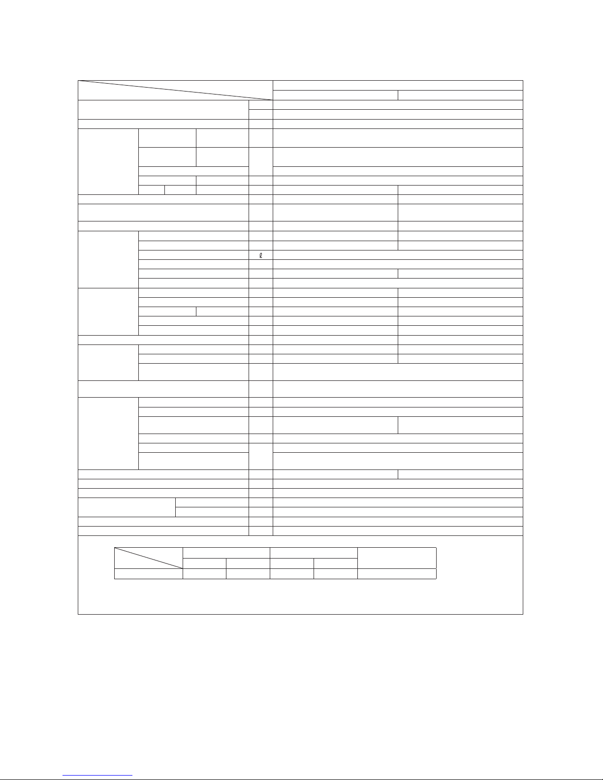
1.1 SPECIFICATIONS
Model
Item
SRK06CJ (-3)
Indoor unit SRK06CJ (-3) Outdoor unit SRC06CJ (-3)
Cooling capacity (1)
W 1500
BTU/h 5000
Power supply 1 Phase, 220 / 230V, 50Hz
Operation
data (1)
Power
consumption
Cooling kW 0.385
Running
current
Cooling
A
1.8
Inrush current 8.5
COP Cooling 3.90
Noise level
Cooling Sound level dB(A) 37 48
Exterior dimensions (Height x Width x Depth) mm 268 x 790 x 213 540 x 645 (+62) x 245
Exterior appearance
(Munsell color)
Fine snow
(8.0Y 9.3/0.1) near equivalent
Stucco white
(4.2Y 7.5/1.1) near equivalent
Net weight kg 8.0 25
Refrigerant
equipment
Compressor type & Q'ty — RMC201A009 (Rotary type) x 1
Motor (Starting method) kW — 0.35 (Line starting)
Refrigerant oil 0.29 (SUNISO 4GSI or ATMOS NM56)
Refrigerant (3) kg R22 0.37 (Pre-Charged up to the piping length of 7.5m)
Heat exchanger Louver fins & inner grooved tubing Louver fins & inner grooved tubing
Refrigerant control Capillary tubes
Air handling
equipment
Fan type & Q'ty Tangential fan x 1 Propeller fan x 1
Motor W 16 22
Air flow Cooling CMM 7.8 24
Fresh air intake Not possible —
Air filter, Quality / Quantity Polypropylene net (washable) x 2 —
Shock & vibration absorber — Cushion rubber (for compressor)
Operation
control
Operation switch Wireless-Remote control —
Room temperature control Microcomputer thermostat —
Operation Display
RUN : Green, TIMER : Yellow, HI POWER : Green,
ECONO : Orange
Safety devices
Frost protection, Fan motor error protection,
Internal thermostat (For compressor)
Installation
data
Refrigerant piping size (O.D) mm Liquid line: φ6.35 (1/4") Gas line: φ9.52 (3/8")
connecting method Flare connecting
Attached length of piping m
Liquid line : 0.4
Gas line : 0.33
—
Insulation for piping Necessary (Both sides), independent
Refrigerant line (one way) length
m
Max. 15
Vertical height difference between
outdoor unit and indoor unit
Max.5 (Outdoor unit is higher)
Max.5 (Outdoor unit is lower)
Drain hose Connectable (VP 16) —
Power cable 2.5m (3 Cores wih Earth)
Recommended breaker size A 20
Connection wiring
Size x Core number 1.5mm2 x 3 cores (Including earth cable)
Connecting method Terminal block (Screw fixing type)
Accessories (included)
Mounting kit
Optional parts —
Note (1) The data are measured at the following conditions.
Item
Operation
Indoor air temperature Outdoor air temperature
Standards
DB WB DB WB
Cooling 27˚C 19˚C 35˚C 24˚C ISO-T1, JIS C 9612
(2) This air-conditioner is manufactured and tested in conformity with the ISO.
(3) The operation data are applied to the 220/230V districts respectively.
(4) The refrigerant quantity to be charged includes the refrigerant in 7.5m connecting piping.
(Purging is not required even for the short piping.)
The pipe length is 7.5m.

-
4
-
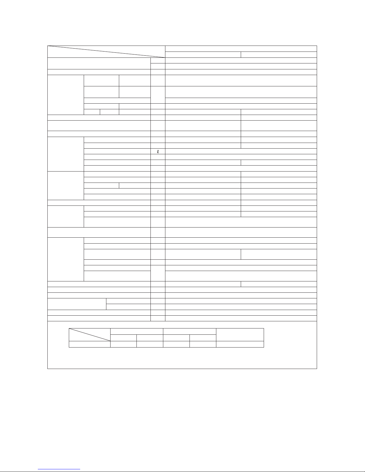
Model
Item
SRK09CJ (-3)
Indoor unit SRK09CJ (-3) Outdoor unit SRC09CJ (-3)
Cooling capacity (1)
W 2640
BTU/h 9000
Power supply 1 Phase, 220 / 230V, 50Hz
Operation
data (1)
Power
consumption
Cooling kW 0.88
Running
current
Cooling
A
4.1
Inrush current 18
COP Cooling 3.00
Noise level
Cooling Sound level dB(A) 41 49
Exterior dimensions (Height x Width x Depth) mm 268 x 790 x 213 540 x 645 (+62) x 245
Exterior appearance
(Munsell color)
Fine snow
(8.0Y 9.3/0.1) near equivalent
Stucco white
(4.2Y 7.5/1.1) near equivalent
Net weight kg 8.0 27
Refrigerant
equipment
Compressor type & Q'ty — RSA201A034 (Rotary type) x 1
Motor (Starting method) kW — 0.68 (Line starting)
Refrigerant oil 0.28 (SUNISO 4GSI or ATMOS NM56)
Refrigerant (3) kg R22 0.41 (Pre-Charged up to the piping length of 7.5m)
Heat exchanger Louver fins & inner grooved tubing Louver fins & inner grooved tubing
Refrigerant control Capillary tubes
Air handling
equipment
Fan type & Q'ty Tangential fan x 1 Propeller fan x 1
Motor W 16 22
Air flow Cooling CMM 9.0 24
Fresh air intake Not possible —
Air filter, Quality / Quantity Polypropylene net (washable) x 2 —
Shock & vibration absorber — Cushion rubber (for compressor)
Operation
control
Operation switch Wireless-Remote control —
Room temperature control Microcomputer thermostat —
Operation Display
RUN : Green, TIMER : Yellow, HI POWER : Green,
ECONO : Orange
Safety devices
Frost protection, Fan motor error protection,
Internal thermostat (For compressor)
Installation
data
Refrigerant piping size (O.D) mm Liquid line :φ6.35 (1/4") Gas line :φ9.52 (3/8")
connecting method Flare connecting
Attached length of piping m
Liquid line : 0.40
Gas line : 0.33
—
Insulation for piping Necessary (Both sides), independent
Refrigerant line (one way) length
m
Max. 15
Vertical height difference between
outdoor unit and indoor unit
Max.5 (Outdoor unit is higher)
Max.5 (Outdoor unit is lower)
Drain hose Connectable (VP 16) —
Power cable 2.5m (3 Cores wih Earth)
Recommended breaker size A 20
Connection wiring
Size x Core number 1.5mm2 x 3 cores (Including earth cable)
Connecting method Terminal block (Screw fixing type)
Accessories (included) Mounting kit
Optional parts —
Note (1) The data are measured at the following conditions.
Item
Operation
Indoor air temperature Outdoor air temperature
Standards
DB WB DB WB
Cooling 27˚C 19˚C 35˚C 24˚C ISO-T1 , JIS C 9612
(2) This air-conditioner is manufactured and tested in conformity with the ISO.
(3) The operation data are applied to the 220/230V districts respectively.
(4) The refrigerant quantity to be charged includes the refrigerant in 7.5m connecting piping.
(Purging is not required even for the short piping.)
The pipe length is 7.5m.
-
5
-
Model
Item
SRK12CJ (-3)
Indoor unit SRK12CJ (-3) Outdoor unit SRC12CJ (-3)
Cooling capacity (1)
W 3450
BTU/h 11800
Power supply 1 Phase, 220 / 230V, 50Hz
Operation
data (1)
Power
consumption
Cooling kW 1.125
Running
current
Cooling
A
5.3
Inrush current 29
COP Cooling 3.07
Noise level
Cooling Sound level dB(A) 42 49
Exterior dimensions (Height x Width x Depth) mm 268 x 790 x 213 540 x 780 (+62) x 290
Exterior appearance
(Munsell color)
Fine snow
(8.0Y 9.3/0.1) near equivalent
Stucco white
(4.2Y 7.5/1.1) near equivalent
Net weight kg 8.5 29
Refrigerant
equipment
Compressor type & Q'ty — RMC201A010 (Rotary type) x 1
Motor (Starting method) kW — 0.92 (Line starting)
Refrigerant oil 0.38 (SUNISO 4GSI or ATMOS NM56)
Refrigerant (3) kg R22 0.57 (Pre-Charged up to the piping length of 7.5m)
Heat exchanger Louver fins & inner grooved tubing Louver fins & inner grooved tubing
Refrigerant control Capillary tubes
Air handling
equipment
Fan type & Q'ty Tangential fan x 1 Propeller fan x 1
Motor W 16 22
Air flow Cooling CMM 10.0 32.0
Fresh air intake Not possible —
Air filter, Quality / Quantity Polypropylene net (washable) x 2 —
Shock & vibration absorber — Cushion rubber (for compressor)
Operation
control
Operation switch Wireless-Remote control —
Room temperature control Microcomputer thermostat —
Operation Display
RUN : Green, TIMER : Yellow, HI POWER : Green,
ECONO : Orange
Safety devices
Frost protection, Fan motor error protection,
Internal thermostat (For compressor)
Installation
data
Refrigerant piping size (O.D) mm Liquid line :φ6.35 (1/4") Gas line :φ12.7 (1/2")
connecting method Flare connecting
Attached length of piping m
Liquid line : 0.4
Gas line : 0.33
—
Insulation for piping Necessary (Both sides), independent
Refrigerant line (one way) length
m
Max. 15
Vertical height difference between
outdoor unit and indoor unit
Max. 5 (Outdoor unit is higher)
Max. 5 (Outdoor unit is lower)
Drain hose Connectable (VP 16) —
Power cable 2.5m (3 Cores wih Earth)
Recommended breaker size A 20
Connection wiring
Size x Core number 1.5mm2 x 3 cores (Including earth cable)
Connecting method Terminal block (Screw fixing type)
Accessories (included) Mounting kit
Optional parts —
Note (1) The data are measured at the following conditions.
Item
Operation
Indoor air temperature Outdoor air temperature
Standards
DB WB DB WB
Cooling 27˚C 19˚C 35˚C 24˚C ISO-T1 , JIS C 9612
(2) This air-conditioner is manufactured and tested in conformity with the ISO.
(3) The operation data are applied to the 220/230V districts respectively.
(4) The refrigerant quantity to be charged includes the refrigerant in 7.5m connecting piping.
(Purging is not required even for the short piping.)
The pipe length is 7.5m.
-
6
-
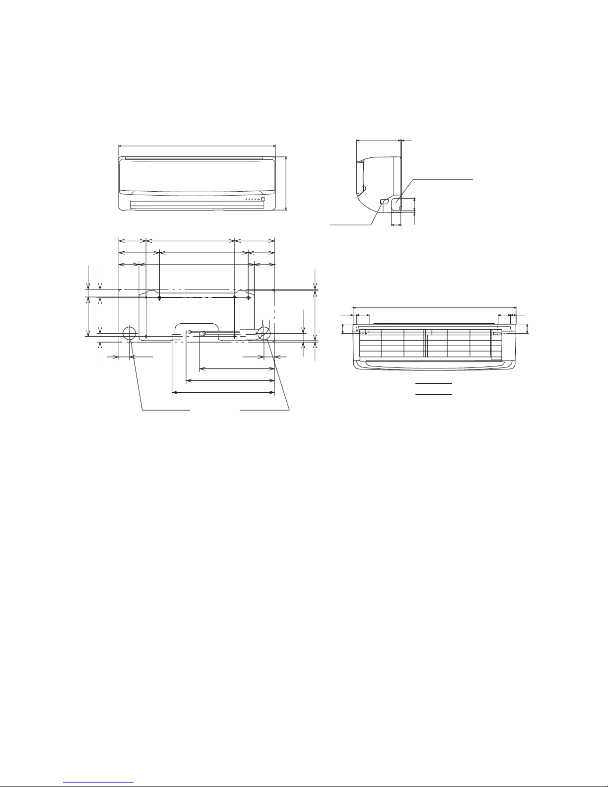
1.2 EXTERIOR DIMENSIONS
(1) Indoor units
Models SRK06CJ(-3), 09CJ(-3), 12CJ(-3)
1.2.2 Range of usage & limitations
1.2.3 Exterior dimensions
Indoor return air temperature
(Upper, lower limits)
m51 .xaMhtgnel )yaw eno( enil tnaregirfeR
All models
Refer to the selection chart
Power source voltage
Rating± 10%
Voltage at starting
Min. 85% of rating
Frequency of ON-OFF cycle
Max. 10 times/h
ON and OFF interval
Max. 3 minutes
Outdoor air temperature
(Upper, lower limits)
Vertical height difference between
outdoor unit and indoor unit
Max. 5m (Outdoor unit is higher)
Max. 5m (Outdoor unit is lower)
Item
Models
(1) Indoor unit
Models SRK06CJ, 09CJ, 12CJ
Unit: mm
Piping hole (ø65)
( )
Piping hole (ø65)
53.5
06, 09 :ø9.52
12 :ø12.7
Piping for Gas
53.5
44.5
7.5
44.5
43.2
39.3
202450138
133.5450206.5
102.5
585
102.5
252.2
8.3
200
380.6
Piping for Liquid 448.6 (ø6.35)
Drain hose 520 (ø16)
45
45
60
17.5
60
27
788
VIEW A
268
790
A
→
Terminal block
Piping hole right (left)
9
213 3
45
60
-
7
-
192.5
372.5
82.5
480
82.5
61.5
2-ø12
Terminal
block
127.7
33.3
40˚
40˚
645
Drain holes
Service valve (Gas)
Flare connecting ø9.52 (3/8˝)
Service valve (Liquid)
Flare connecting ø6.35 (1/4˝)
50
12
42
13.5
274.5
300
12
23
44
245
540
100.3 39.7
14.4
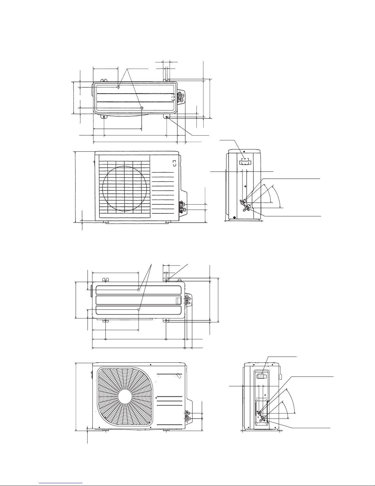
(2) Outdoor unit
Model SRC06CJ(-3), 09CJ(-3)
Model SRC12CJ (-3)
Unit: mm
63.4
390.6
390.6
69.4
111.6 510 158.4
780 61.9
17.9
14.8 312.5 24.3
351.6
50.6
12
290
Anchor bolt hole
Drain discharge holes
Service valve (Gas)
Flare connection
ø12.7 (1/2")
15.8
540
97.7
42.5
40
˚
40˚
138.4 33.5
Terminal block
Service valve (Liquid)
Flare connection
ø6.35(1/4")
Unit: mm
-
8
-
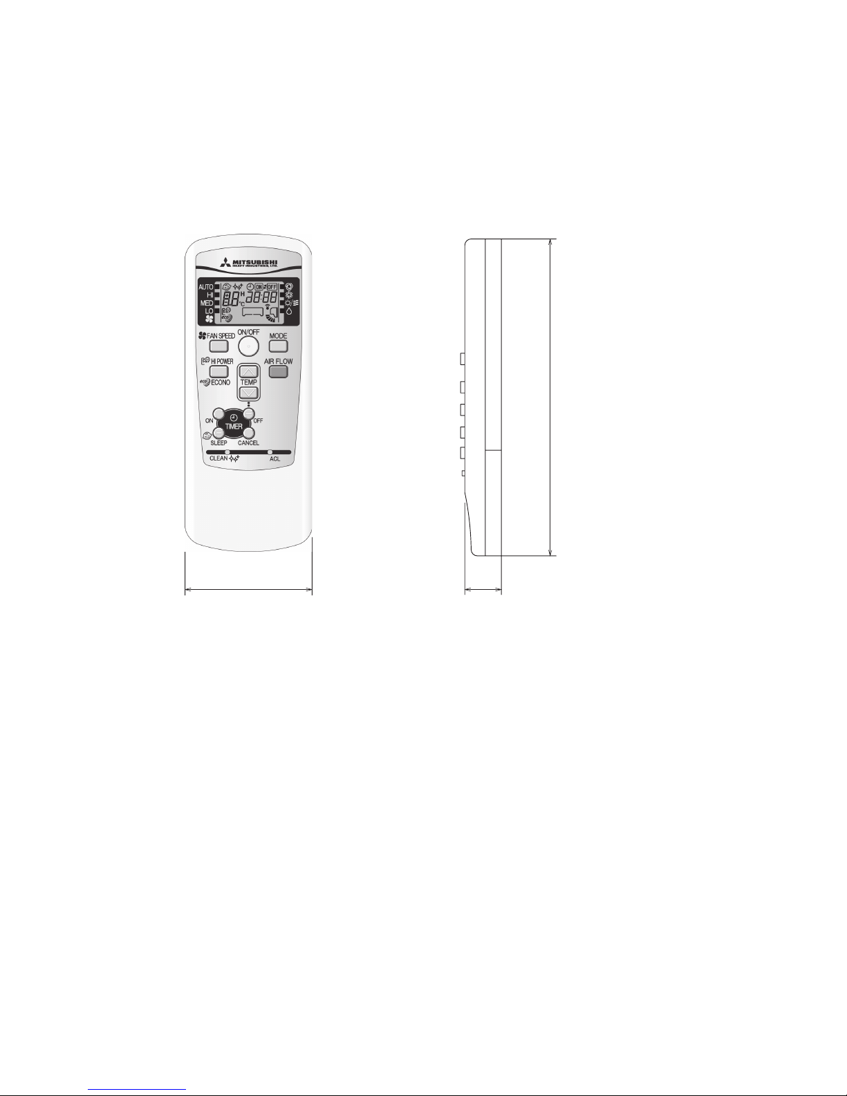
(3) Wireless remote controller
Unit: mm
60
17.3
150
-
9
-
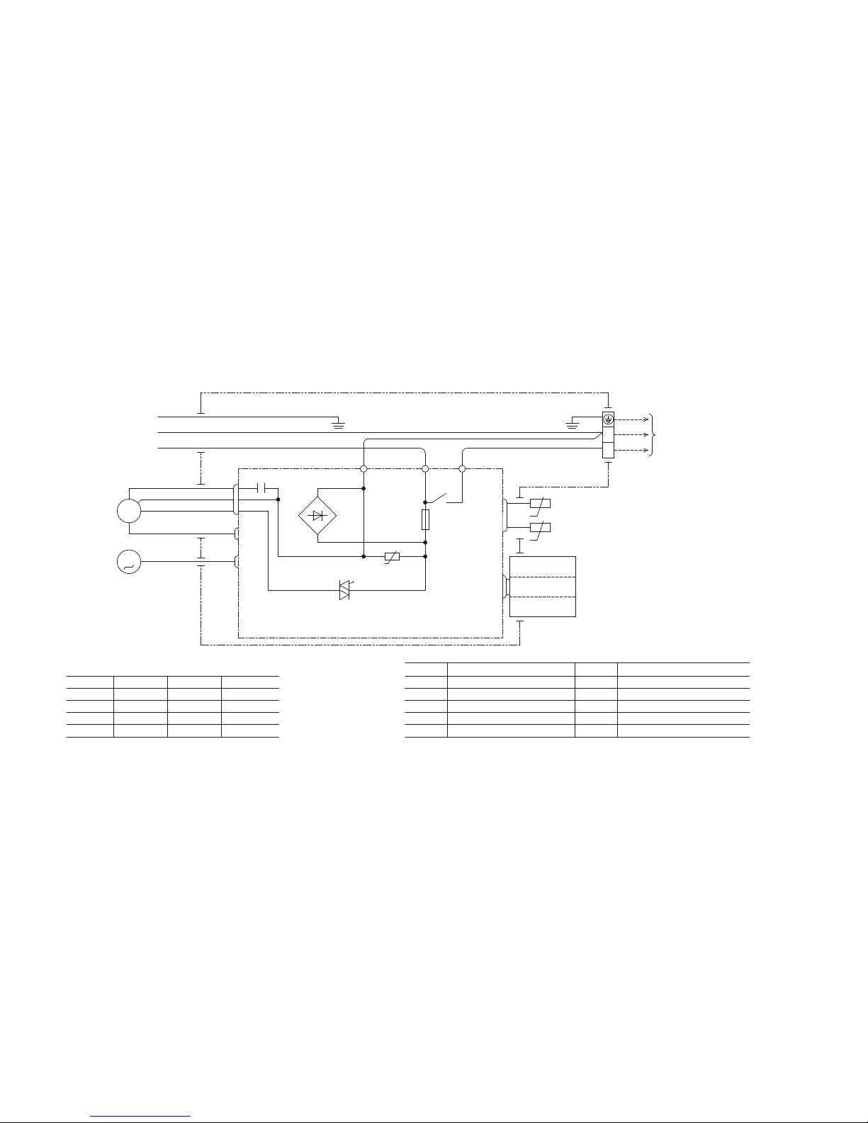
1.3 ELECTRICAL WIRING
(1) Indoor units
Models SRK06CJ(-3), 09CJ(-3), 12CJ(-3)
U
MFM
BK
Color symbol
BL
BR
LB
YE
RD
YG
WH
Red
Yellow/Green
White
Black
Blue
Brown
Light blue
Yellow
Symbol
Meaning of Marks
Parts name Symbol Parts name
Capacitor forCF
I
FM
I
FM
ZNR
FM
I
Fuse
Fan motor
Flap motor
Varistor
Th2
T
Room temp. thermistor
Heat exchanger thermistor
Terminal block
F
Th1
Power source
220/230/240V 50Hz
YG
LB
BR
Printed circuit board
T
YG
BL
BR
WH
BK
TO
OUTDOOR
UNIT
Th1
Th2
Wireless
R-Amp
Display
CNE
CNG
YE
WH
RD
M
CNW
IC15
ZNR
1
5
3
CNU
CF
I
52C-4 52C-3
52C
F
250V 3.15A
CONTROL BOX
1
2
Back up Sw
CNM
N
t°
1~
FM
I
t°
-
10
-
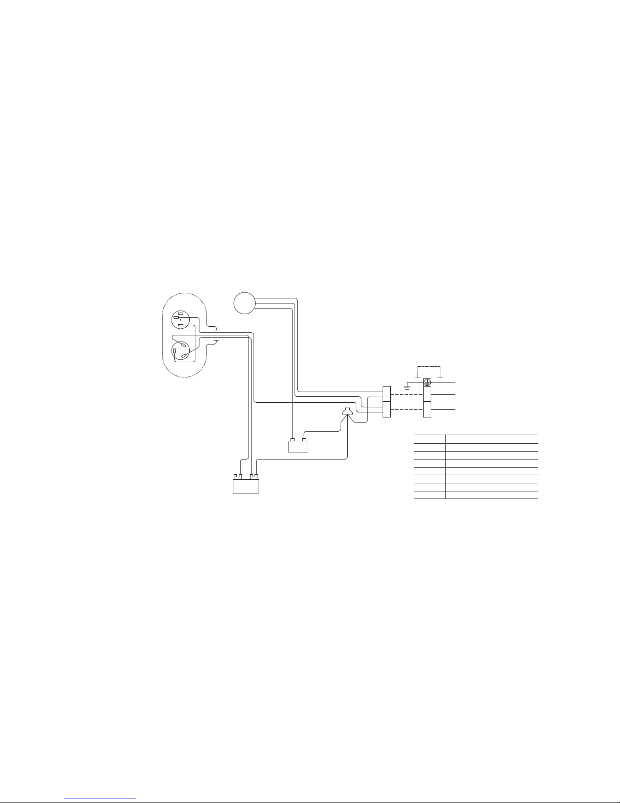
(2) Outdoor units
Models SRC06CJ(-3), 09CJ(-3), 12CJ(-3)
Symbol
Meaning of Marks
Parts name
Capacitor for CMCc
Capacitor for FMoCFo
Compressor motorCM
Fan motorFMo
Motor protector for CM51C
Terminal blockT
ConnectorSh
1
Power source
220-240V 50Hz
INDOOR
UNIT
FMo
BLACK
ORANGE
WHITE
RED
WHITE
Cc
ORANGE
CFo
WHITE
ORANGE
WHITE
WHITE
BLACK
BLACK
WHITE
1 2
T
WHITE
CM
BLACK
BLACK
51C
2
3
1
RED
C
S
R
Sh
1
T
WHITE
1 2
CAPACITOR
-
11
-
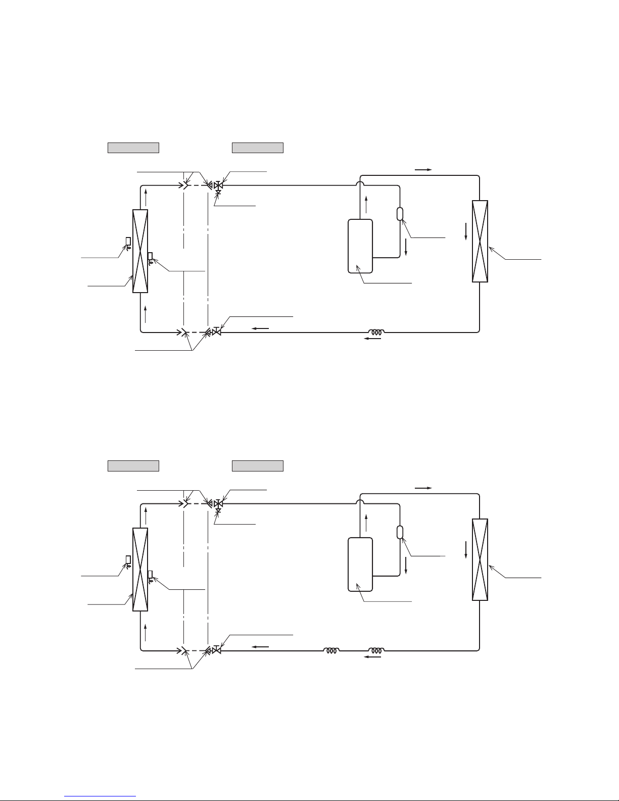
1.4 PIPING SYSTEM
Model SRK06CJ-3, 09CJ-3
Model SRK12CJ-3
Outdoor unitIndoor unit
Room temp.
sensor
Heat
exchanger
Flare connecting
Heat
exchanger
sensor
Piping
(Liquid)
ø6.35
Check joint
Service valve (Liquid)
Flare connecting
Cooling cycle
Heat
exchanger
Compressor
Accumulator
Service valve
(Gas)
Capillary tube
Piping
(Gas)
ø9.52
Outdoor unitIndoor unit
Room temp.
sensor
Heat
exchanger
Flare connecting
Heat
exchanger
sensor
Piping
(Liquid)
ø6.35
Check joint
Service valve (Liquid)
Flare connecting
Cooling cycle
Heat
exchanger
Compressor
Capillary tube
Accumulator
Service valve
(Gas)
Capillary tube
Piping
(Gas)
ø12.7
1.4 PIPING SYSTEM
Models SRK06CJ(-3), 09CJ(-3)
Model SRK12CJ (-3)
-
12
-
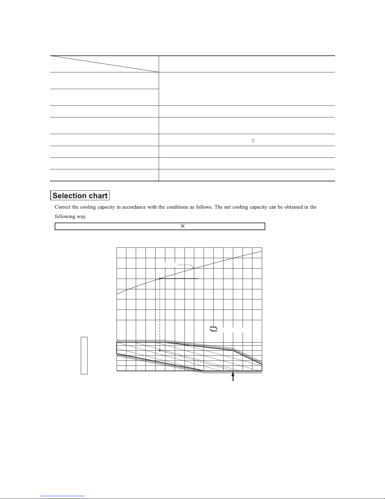
1.5 RANGE OF USAGE & LIMITATIONS
Net capacity = Capacity shown on specification Correction factors as follows.
(1) Coefficient of cooling capacity in relation to temperatures
All models
Models
Item
Indoor return air temperature
(
Upper, lower limits
)
Outdoor air temperature
(
Upper, lower limits
)
Refer to the selection chart
Refrigerant line (one way) length
Max. 15m
Max. 5m (Outdoor unit is higher
)
Max. 5m (Outdoor unit is lower
)
Min. 3 minutes
Max. 10 times/h
Min. 85% of rating
Vertical height difference between
outdoor unit and indoor unit
Power source voltage
Voltage at starting
Frequency of ON−OFF cycle
ON and OFF interval
Rating 10%
14 16 18 20 22
15
20
25
30
35
40
0.6
0.7
0.8
0.9
1.0
1.1
1.2
1.3
43
24
ISO-T1 Standard ConditionIndoor air W.B. temperature °C W.B.
Cooling
Applicable range
Coefficient of cooling
capacity in relation
to temperature
Cooling operation
Outdoor air D.B.
temperature
°C D.B.
-
13
-
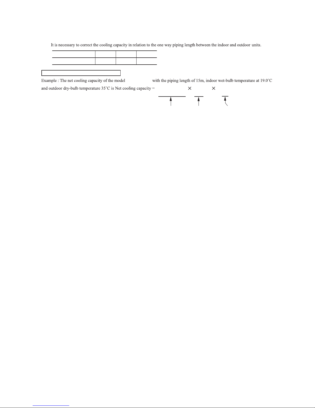
(2) Correction of cooling capacity in relation to one way length of refrigerant piping
How to obtain the cooling capacity
Piping length [m]
Cooling
7
1.0
10
0.99
15
0.975
SRK12CJ (-3)
SRK12CJ (-3)
(11500 BTU/h)
Length 15m
Factor by air
temperatures
(11800 BTU/h)
3450W 0.975
1.0 3364 W
=
-
14
-
1.6 APPLICATION DATA
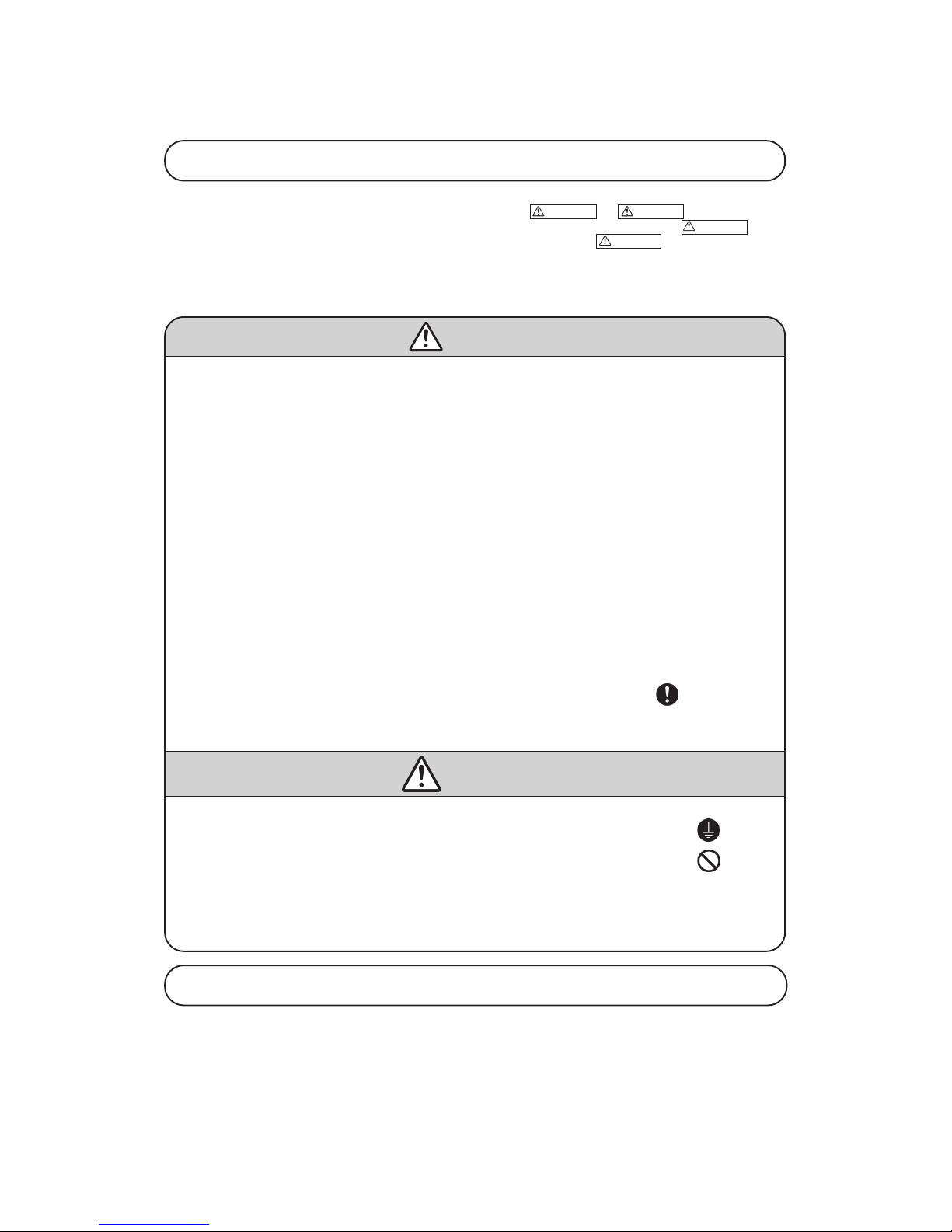
Safety precautions
• Please read these “Safety Precautions” first then accurately execute the installation work.
• Though the precautionary points indicated herein are divided under two headings,
WARNING and CAUTION , those points which ar e
related to the strong possibility of an installation done in error resulting in death or serious injury are listed in the
WARNING section.
However, there is also a possibility of serious consequences in relationship to the points listed in the
CAUTION section as well. In either case,
important safety related information is indicated, so by all means, properly observe all that is mentioned.
• After completing the installation, along with confirming that no abnormalities were seen from the operation tests, please explain operating
methods as well as maintenance methods to the user (customer) of this equipment, based on the owner’s manual.
Moreover, ask the customer to keep this sheet together with the owner’s manual.
WARNING
• To disconnect the appliance from the mains supply this appliance must be connected to the mains by means of a circuit breaker or a switch
(use a recognized 20A) with a contact separation of at least 3mm.
• The appliance shall be installed in accordance with national wiring regulations.
• This system should be applied to places as households, residences and the like. Application to inferior environment such as engineering
shop could cause equipment malfunction.
• Please entrust installation to either the company which sold you the equipment or to a professional contractor. Defects from improper
installations can be the cause of water leakage, electric shocks and fires.
• Execute the installation accurately, based on following the installation manual. Again, improper installations can result in water leakage,
electric shocks and fires.
• For installation, confirm that the installation site can sufficiently support heavy weight. When strength is insufficient, injury can result from
a falling of the unit.
• For electrical work, please see that a licensed electrician executes the work while following the safety standards related to electrical
equipment, and local regulations as well as the installation instructions, and that only exclusive use circuits are used.
Insufficient power source circuit capacity and defective installment execution can be the cause of electric shocks and fires.
• This equipment must be installed with earth leakage circuit breaker (ELCB). Otherwise, it may cause electrical shock and fire
in case of
equipment breakdown.
• Accurately connect wiring using the proper cable, and insure that the external force of the cable is not conducted to the terminal connection
part, through properly securing it improper connection or securing can result in heat generation or fire.
• Take care that wiring does not rise upward, and accurately install the lid/service panel.It’s improper installation can also result heat generation or fire.
• When setting up or moving the location of the air conditioner, do not mix air etc. or anything other than the designated refrigerant (R22)
within the refrigeration cycle.
Rupture and injury caused by abnormal high pressure can result from such mixing.
• Always use accessory parts and authorized parts for installation construction. Using parts not authorized by this company can result in
water leakage, electric shock, fire and refrigerant leakage.
• Ventilate the work area when refrigerant leaks during the operation.
Coming in contact with fire, refrigerant could generate toxic gas.
• Confirm after the foundation construction work that refrigerant does not leak.
If coming in contact with fire of a fan heater, a stove or movable cooking stove, etc., refrigerant leaking in the room could generate toxic gas.
CAUTION
• Execute proper grounding. Do not connect the ground wire to a gas pipe, water pipe, lightning rod or a telephone ground wire.
Improper placement of ground wires can result in electric shock.
• The installation of an earth leakage breaker is necessary depending on the established location of the unit.
No installing an earth leakage breaker may result in electric shock.
• Do not install the unit where there is a concern about leakage of combustible gas.
The rare even of leaked gas collecting around the unit could result in an outbreak of fire.
• For the drain pipe, follow the installation manual to insure that it allows proper drainage and thermally insulate it to prevent condensation.
Inadequate plumbing can result in water leakage and water damage to interior items.
• Install the outdoor unit so that the aluminum fins on the air heat exchanger cannot be touched. Failure to observe this may result in injury.
• Do not place objects near the outdoor unit or allow leaves to gather around the unit. If there are objects or leaves around the outdoor unit,
small animals may enter unit and contact electrical parts resulting in break down, emission of smoke or flame.
Cautions for installation
① The system should be applied to places as households, residences and the like.
② The equipment shall be installed in accordance with national wiring regulations.
③ The connection to the fixed wiring of the mains supply must be made via a double pole isolating switch with a contact gap of at
least 3mm in each pole.
④ When the outdoor unit has a possibility of being overturned or being displaced and fall from its original installation position, the
outdoor unit should be fixed in its position by use of anchor bolts or wires.
-
15
-
Necessary tools for the installation work
1 Plus headed driver (Phillips screwdriver)
2 Knife
3 Saw
4 Tape measure
5 Hammer
6 Spanner wrench
7 Torque wrench
8 Hole core drill (65mm in diameter)
9 Wrench key (Hexagon)
[4m/m]
10 Vacuum pump
11
Vacuum pump adapter
(Anti-reverse flow type)
12 Gauge manifold
13 Change hose
14 Flaring tool set
15 Gas leak detector
( )
Standard accessories
(Installation kit) Q'ty
Accessories for indoor unit
①
Installation board
1
(Attached to the rear of the indoor unit)
② Wireless remote control 1
③ Remote contorol holder 1
④
Tapping screws
4
(for installation board 4dia. by 25mm )
⑤
Wood screw
2
(for remote contorol switch holder 3.5dia. by 16mm)
⑥
Baterry [R03 (AAA, Micro) 1.5V]
2
Option parts Q'ty
ⓐ 1etalp gnilaeS
ⓑ 1eveelS
ⓒ 1etalp noitanilcnI
ⓓ 1yttuP
ⓔ Drain hose (extention hose) 1
ⓕ
Piping cover (for insulation of
1
connection piping)
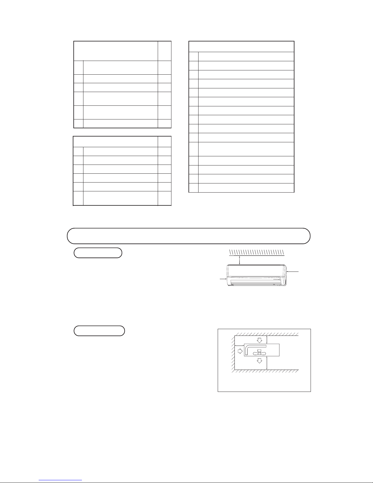
① A place where good air circulation can be obtained and where rain,
snow or sunshine will not directly strike the unit.
② A place where discharged hot air or unit’s operating sound will not
be a nuisance to the neighborhood.
③ A place where servicing space can be secured.
④ A place where vibration will not be enlarged.
*Avoid installing in the following places.
•A place near the bedroom and the like, so that the operation
noise will cause no trouble.
•
A place where there is possibility of flammable gas leakage.
•A place exposed to strong wind.
⑤ Blowing out port and suction port on the back side of the unit can
be installed at a distance of 10cm from walls.
In case the barrier is 1.2m or above in height, or is overhead, the
sufficient space between the unit and wall shall be secured.
⑥ When the unit is installed, the space of the following dimension
and above shall be secured.
OUTDOOR UNIT
Note (1) If the wall is higher than 1.2 m or a ceiling is
present, distances larger than indicated in the
above table must be provided.
Selection of installation location
① Where there is no obstructions to the air flow and where the
cooled air can be evenly distributed.
② A solid place where the unit or the wall will not vibrate.
③ A place where there will be enough space for servicing. (Wher e
space mentioned right can be secured)
④ Where wiring and the piping work will be easy to conduct.
⑤ The place where receiving part is not exposed to the direct rays
of the sun or the strong rays of the street lighting.
⑥ A place where it can be easily drained.
⑦ A place separated at least 1m away from the television or the
radio.
(To prevent interfence to images and sounds.)
INDOOR UNIT
6.5 cm
5 cm
10 cm
Left
side
14.0 ~ 61 .0N · m
(1.4 ~ 6. 1kgf · m)
( )
Designed specifical ly
for R22
( )
Designed specifica lly
for R22
( )
Designed specifica lly
for R22
( )
Designed specifica lly
for R22
( )
Designed specifica lly
for R22
60 cm MIN
Air intake
10 cm MIN
10 cm
MIN
Air outlet
Air
intake
No obstacles
(Service space
for electrical
parts)
Right
side
)(
-
16
-
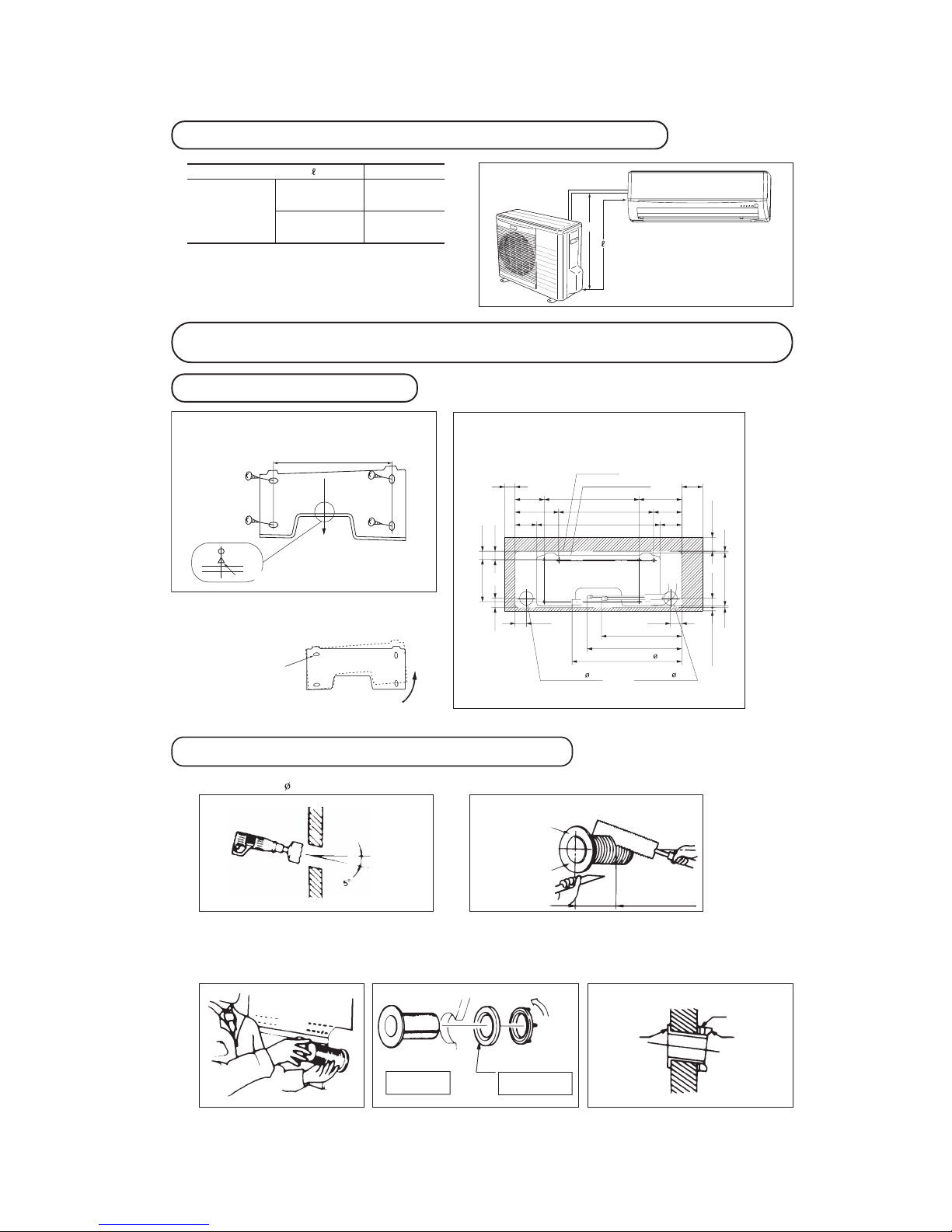
Installation of indoor unit
Installation of installation board
• Adjustment of the installation board in the horizontal
direction is to be conducted with four screws in a
temporary tightened state.
• Adjust so that board will be level by turning the board
with the standard hole as the center.
Standard hole
Look for the inside wall structures (Intersediate support or
pillar and firaly install the unit after level surface has been
checked.)
Mating mark for level surface
450
INSTALLATION SPACE (INDOOR UNIT) (FRONT VIEW)
Unit : mm
Piping hole( 65) Piping hole( 65)
Installation board
Indoor unit
53.5
Piping for Gas 380.6
Piping for Liquid 448.6
Drain hose 520( 16)
53.5
Space *
for service
Space
for service
44.5
252.2
7.5
8.3
Space for
service
50
Space for
service
100
102.5
585
102.5
133.5
450206.5
202450138
44.5
43.2
39.3
200
65
15
Limitations for one way piping length and vertical height difference
One way piping length ( ) 15 m
Outdoor
unit is lower
5 m
Outdoor unit
is higher
5 m
Vertical height
difference (h)
h
Drilling of holes and fixture sleeve (Option parts)
(Insertin g sleeve)
Note (1) Drill a hole with incline of 5 degree from
indoor si de to outd oor side.
Indoor side Outdoor side
Cut off the sle eve
col lar in cas e of
dr aw in g p ipin g
out to rear.
Cut off the sle eve
collar that can be
seen from ben eath
the unit.
Wall thic kness
+ 1.5 cm
Indoor side Outdoor side
Turn t o
tighten
Paste
View of sleeve when installed
In cl ined
flange
Seal ing
plate
Sleeve
Indoor side Outdoor side
(*Sleeve + *Inclined + *Sealing plate)
Drill a hole with 65 whole core drill Adjusting sleeve length
Install the sleeve
*Leave e xtra space on the r ight side to enable removal o f the lid screw.
-
17
-
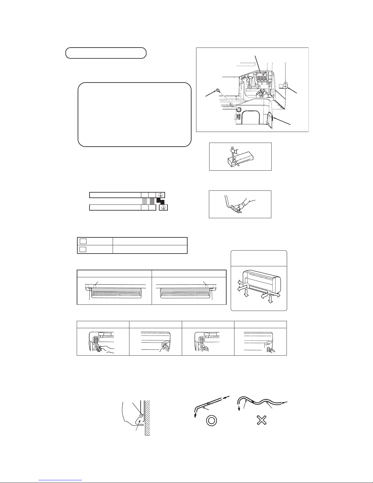
Preparation of indoor unit
Pipe
Drain hose
[Procedure for exchanging the drain hose.]
1. Remove the drain hose. 2. Remove the drain cap. 3. Insert the drain cap. 4. Connect the drain hose.
① Mounting of connecting wires
ⓐ Remove the lid.
ⓑ Remove the wiring clamp.
ⓒ Connect the connecting wire securely to the terminal block.
Use cable for interconnection wiring to avoid loosening of the
wires.
CENELEC code for cables Required field cables.
H05RNR3G1.5 (Example) or 245IEC57
H Harmonized cable type
05 300/500 volts
R Natural-and/or synth. rubber wire insulation
N Polychloroprene rubber conductors insulation
R Standed core
4or5 Number of conductors
G One conductor of the cables is the earth conductor (yel-
low/green)
1.5 Section of copper wire (mm
2
)
• Connect the connection wire securely to the terminal block.
If the wire is not affixed completely, contact will be poor,
and it is dangerous as the terminal block may heat up and
catch fire.
• Take care not to confuse the terminal numbers for indoor
and outdoor connections.
• Earth lead wire shall be longer than the other lead wires for
the electrical safety in case of the slipping out of the cord
from the anchorage.
• The earth line of power cord must be properly earthed.
• Affix the connection wire using the wiring clamp.
ⓓ Fix the connecting wire by wiring clamp.
ⓔ Attach the lid.
ⓕ Close the air inlet panel.
For power supply, indoor unit
For power supply, outdoor unit
1 Brown
2 Blue
② Shaping the pipe
③ Taping of the exterior
• Hold the bot tom of the pip e and change its directio n before
stretchin g it and s haping it.
• Tape only the portio n that run s through the wall.
Always ta pe the cro ssover wir es with th e pipe.
④ Cautions when piping from the left and the rear center of the unit
[ Top View ]
• Loo sen a nd re mov e the
spring-t ype clamp.
• Remove with your hand or
a pair of pliers.
•
Use a hexag onal wrench to
correctl y ins ert t he dr ain c ap
which wa s removed in 2.
Cautio n: Be c areful because
if the cap is not inserte d property, wa ter leak m ay occur.
•
Loosen the spri ng-type clamp
and securely insert the dra in
hose.
Cautio n: Be c areful becaus e
if the cap is not inserte d properly, wa ter leak m ay occur.
gnipiP ediS thgiRgnipiP ediS tfeL
Right rear pipingLeft rear piping
gnipip edis thgiRgnipip edis tfeL
Lid
Screw *
Clamp
Terminal block
[ Procedure for exchanging the drain hose ]
Left downward
Right
Rear
Downward
Left rear
Left
Piping is possi ble in the rear, left,
left rear, left downw ard, right or
downward direction.
• Do not pla ce the po wer supply cords ab ove the gu tter, bec ause the
air conditioner is str uctured in a way where condensation on t he
back side is collec ted in to the drain pan before drainage.
• Do not make traps in the drain hose line .
* Leave space t o a llow
removal of this scre w
after in stallation .
Terminals on the indoor unit
Colour of wires
Terminals on the outdoor unit
112
2
Wall
Gutter
Pipes storage area
Declining slope
Inverted slipe
Trap
-
18
-
Installing steps
1.Hook the upper part
of the indoor unit to
the installation board.
2.The unit can be installed
simply by gently pushing in the lower part.
⑤ Securing the indoor unit to the installation board
Wall
Indoor un it
base lowe r latch
Installa tion
board
Latch ( 2 locati ons)
Installa tion
board
Indoor un it
•
How to remove the indoor unit from the installation board
① Push up at the marked portion of the indoor unit
base lower latch, and slightly pull it toward you.
(both right and left hand sides)
(The indoor unit base lower latch can be removed
from the installation board)
② Push up the indoor unit upward. So the indoor unit
will be removed from the installation board.
The marked portion of the
Indoor unit bese lower latch
Lid
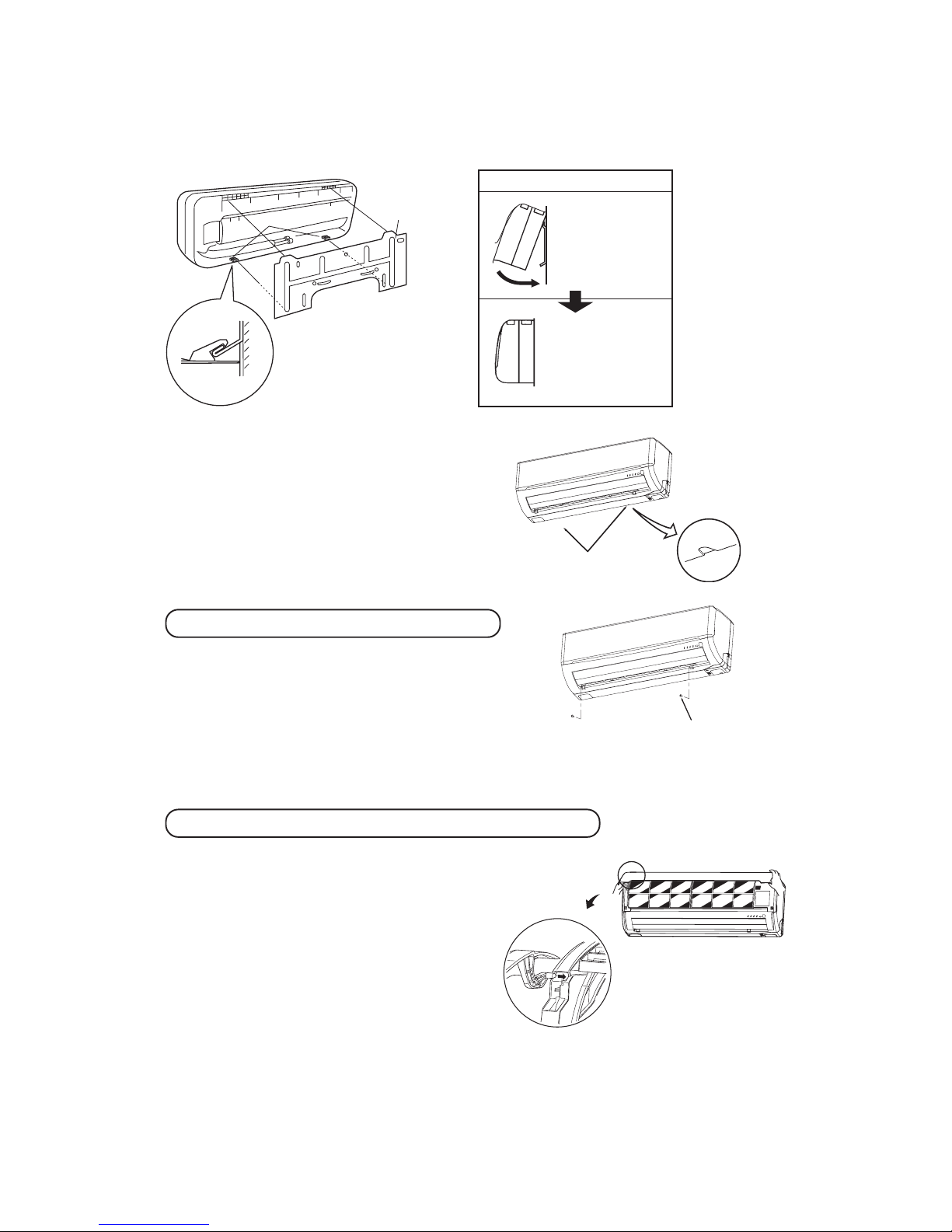
Removal and installation of the front panel
Open/close and detachment/attachment of air inlet panel
Set scre ws
① Removing
• Remove the 2 set screws.
• Move the lower part of the panel forward and push upwards to
remove. (Remove the 3 latches in the upper section.)
② Fitting
• Do remove the air filter.
• Cover the body with the front panel.
• Push the circled portion at the front.
• Tighten the 2 set screws.
• Fit the air filter. Carry out in the above order.
① To open, pull the panel at both ends of lower part and release
latches, then pull up the panel until you feel resistance. (The
air inlet panel stops at approx. 60˚ open position.)
② To close, hold the panel at both ends of lower part to lower
downward and push it slightly until the latch works, then
push the center portion slightly.
③ To remove, pull up the panel to the position shown in right
illustration and pull it toward you.
④ To install, insert the air inlet panel arm into the slot on the
front panel from the position shown in right illustration, hold
the panel at both ends of lower part, lower it downward
slowly, then push it slightly until the latch works and further
push the center portion slightly.
-
19
-
1 2
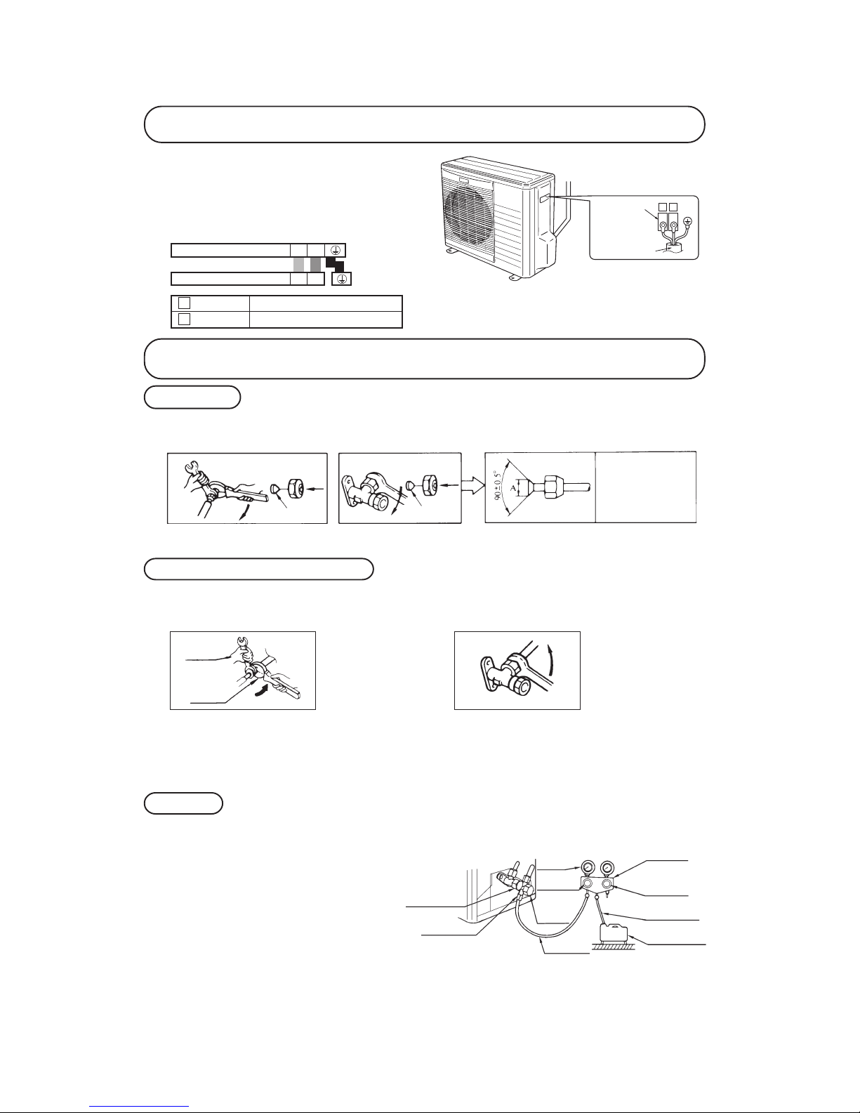
Installation of outdoor unit
① Make sure that the unit is stable in installation. Fix the
unit to stable base.
② Perfrom wiring, making wire terminal numbers conform
to terminal numbers of indoor unit terminal block.
③ Earth lead wire shall be longer than the other lead wires
for the electrical safety in case of the slipping out of the
cord from the anchorage.
Terminal block
Intercon necting wire
Connection of refrigerant pipings
Preparation
Connection of refrigerant piping
Air purge
Keep the openings of the pipes covered with tapes etc. to prevent dust, sand, etc. from entering them.
• Specified torquing value:
Liquid side (ø6.35) : 14~18N·m (1.4~1.8kgf·m)
Gas side (ø9.52) : 34~42N·m (3.4~4.2kgf·m)
Gas side (ø12.7) : 49~61N·m (4.9~6.1kgf·m)
• Use one more spanner to fix the valve.
① Tighten all flare nuts in the pipings both indoor and
outside wall so as not to cause leak.
② Connect service valve, charge hose, manifold valve
and vacuum pump as is illustrated below.
③ Open manifold valve handle Lo to its full width, and
perform vacuum or evacuation.
Continue the vacuum or evacuation operation for 15
minutes or more and check to see that the vacuum
gauge reads – 0.1 MPa (– 76 cmHg).
④ After completing vacuum operation, fully open serv-
ice valve (Both gas and liquid sides) with hexagon
headed wrench.
⑤ Detach the charge hoses.
⑥ Check for possible leakage of gas in the connection
parts of both indoor and outdoor.
¡ R emove the flared nu ts.
(on both liquid and gas sides )
¡ Remove the flared nut s.
(on both l iquid and ga s sides)
¡ Install t he remo ved flar ed nuts to the pipe s to b e con-
nected, t hen flare the pipes.
Dimension A
Liquid si de
(ø6.35): 9.0 dia
Gas side
(ø9.52): 13. 0 dia
(ø12.7): 16.2 dia
Press
Remove
Remove
(D o no t
turn)
Spanner
for fixin g
the pipin g)
Torque
wrench
• Specified torquing value:
Liquid side (ø6.35) : 14~18N·m (1.4~1.8kgf·m)
Gas side (ø9.52) : 34~42N·m (3.4~4.2kgf·m)
Gas side (ø12.7) : 49~61N·m (4.9~6.1kgf·m)
① Indoor unit side
② Outdoor unit side
① Indoor unit side ② Outdoor unit side
• Connect firmly gas and liquid side
pipings by Torque wrench.
• Connect firmly gas and liquid side
pipings by Torque wrench.
• Always use a Torque wrench and back up spanner to tighten the flare nut.
Ma ni fo ld
Valve
-76 cm H g
Handle Lo
(pressur e)
Charge h ose
Stop valv e
(Two-way valve)
Service p ort
Stop valu e
(Three- way
value)
Compound
(Gauge)
Pressure
gauge
Handle H i
(pressure)
Charge h ose
Vacuum pu mp
Terminals on the indoor unit
Colour of wires
Terminals on the outdoor unit1122
For power supply, indoor unit
For power supply, outdoor unit
1 Brown
2 Blue
-
20
-
When refrigerant piping exceeds 7.5m conduct additional refrigerant charge after refrigerant sweeping.
7.5m over 15m:Additional charge amount per meter = 10g/m
[Example]
How much amount of additional charge for 15m piping?
(15 – 7.5)m × 10g/m=75g 75g for additional charge
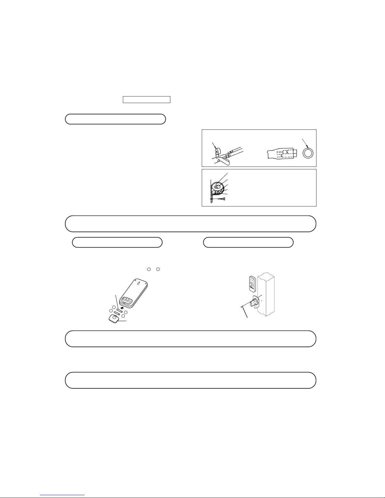
Installation of remote control switch
Insulation of connecting portion
Mounting method of battery
Earthing work
① Cover the connection portion of the refrigerant piping with the
pipe cover and seal them.
If neglecting to do so, moisture occurs on the piping and water
will drip out.
② Finishing and fixing
ⓐ Tie up the piping with wrapping tape, and shape it so that it conforms
to which the pipe is attached.
ⓑ Fix them with clamps as right figure.
Vinyl tap e
To cov er the connecting po rtion w ith ins ulation materia ls, cut upper porti on and then seal
it with i nsulation materials.
Cover the exter ior portion with covering tape a nd shape the pi ping so it
will matc h the cont ours of th e route
that t he pipi ng to take. Also fix the
wiring and pipings to the wal l with
clamps.
Insulatio n
Refrigera nt piping
Electrica l wiring
Covering tape
Drain hos e
Tapping s crew
-
-
-
+
+
+
• Uncover the remote control switch, and mount the batteries [R03(AAA, Micro)× 2 pieces] in the body regularly.
(Fit the poles with the indication marks, & without
fail)
• Earth work shall be carried out without fail in order to prevent electric shock and noise generation.
• The connection of the earth cable to the following substances causes dangerous failures, therefore it shall never be done.
City water pipe, Town gas pipe, TV antenna, lightning conductor, telephone line, etc.
Trial run and operation
① Conduct trial run after confirming that there is no gas leaks.
② When conducting trial run set the remote control thermostat to continuous operation position. However when the power source
is cut off or when the unit’s operation switch is turned off or was turned to fan operation position, the unit will not go int o
operation in order to protect the compressor.
③ Explain to the customer on the correct usage of the air-conditioner in simple layman’s terms.
④ Make sure that drain flows properly.
Battery
Cover
Fixing to pillar or wall
• Conventionally, operate the wireless remote control
by holding in your hand.
• Avoid installing it on a clay wall etc.
Screws
♦ Additional refrigerant charge
-
21
-
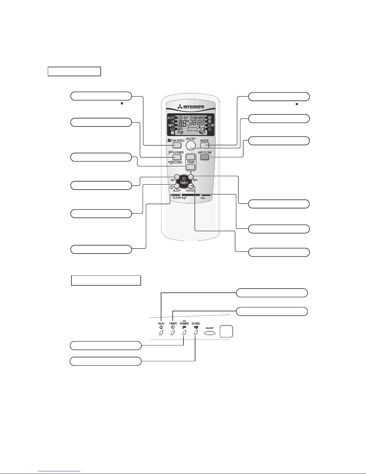
Remote controller
1.7
OUTLINE OF OPERATION CONTROL BY MICROCOMPUTER
(1) Operation control function by remote controller
S
Operation section
Unit display section
FAN SPEED button
Each time the button is pushed, the
indicator is switche d over in t urn.
•
The above illustrati on shows al l controls, but in pr actice
only the relevant pa rts are sho wn.
OPERATION MODE select button
Each time the button pushed, th e
indicator is switche d over in t urn.
ON/OFF (luminous) button
Press for starting o peration, p ress again
for stopp ing.
HI POWER/ECONO button
This butt on ch anges th e HIG H POWER/
ECONOMY m ode.
AIR FLOW (UP/DOWN) button
This butt on changes the air flo w (up/down) mode.
SLEEP button
This butt on selects SLEEP opera tion.
CLEAN switch
This swit ch changes the CLEAN m ode.
ON TIMER button
This butt on selects ON TIMER op eration.
Thi s b utto n can cel s th e ON TIM ER, OFF
TIMER, an d SLEEP ope ration.
CANCEL button
RESET switch
Switch fo r resetting microcompu ter and
setting t ime.
OFF TIMER button
This butt on selects OFF TIMER o peration.
TEMPERATURE button
This butt on sets the room tempe rature.
(This but ton changes the presen t time and
TIMER tim e.)
RUN light (green)
Illuminat es during o peration
and ‘CLEA N operation ’.
TIMER light (yellow)
Illuminat es during T IMER opera tion.
HI POWER light (green)
Illuminat es during H IGH POWER operation.
ECONO light (orange)
Illuminat es during E CONOMY ope ration.
-
22
-
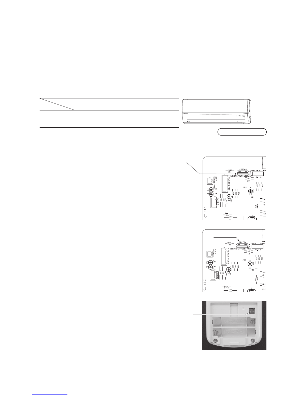
(4) Custom cord switching procedure
If two wireless remote controller are installed in one room, in order to prevent wrong operation
due to mixed signals, please modify the printed circuit board in the indoor unit’s control box
and the remote controller using the following procedure. Be sure to modify both boards. If
only one board is modied, receiving (and operation) cannot be done.
(a) Modifying the indoor unit’s printed circuit board
Take out the printed circuit board from the control box and cut off jumper wire (J6)
using wire cutters.
After cutting of the jumper wire, take measures to prevent contact with the other the lead
wires, etc.
(2) Unit ON/OFF button
When the remote controller batteries become weak, or if the remote controller is lost or malfunctioning, this button may be used to
turn the unit on and off.
(a) Operation
Push the button once to place the unit in the automatic mode. Push it once more to turn the unit off.
(b) Details of operation
The unit will go into the automatic mode in which it automatically determines, from room temperature (as detected by sensor),
whether to go into the cooling or thermal dry modes.
(3) Auto restart function
(a) Auto restart function records the operational status of the air-conditioner immediately prior to be switched off by a power cut,
and then automatically resumes operations after the power has been restored.
(b) The following settings will be cancelled:
1) Timer settings
2) HIGH POWER operations
Notes (1) Auto restart function is set at on when the air-conditioner is shipped from the factory. Consult
with your dealer if this function needs to be switched off.
(2) When power failure ocurrs, the timer setting is cancelled. Once power is resumed, reset the timer.
(3)
If the jumper wire (J7) “AUTO RESTART” is cut, auto restart is disabled. (See the diagram at right)
(b) Modifying the wireless remote controller
1) Remove the battery.
2) Cut the jumper wire shown in the gure at right.
Cut
Function
Operation mode
Room temperature
setting
Fan speed
Flap
Timer switch
Cooling
About 23ºC
Auto Auto Continuous
Thermal dry
About 24ºC
Unit ON/OFF button
In emergen cies, this button c an be used for turni ng on/off the unit when
remote con trol is not availab le.
Page 15
RUN light (green)
Illuminate s during operation
and CLEAN operation.
TIMER light (yellow)
Illuminate s during TIMER oper ation.
Unit ON/OFF button
Jumper wire (J7)
Jumper wire (J6)
-
23
-
'09•SRK-DB-087D
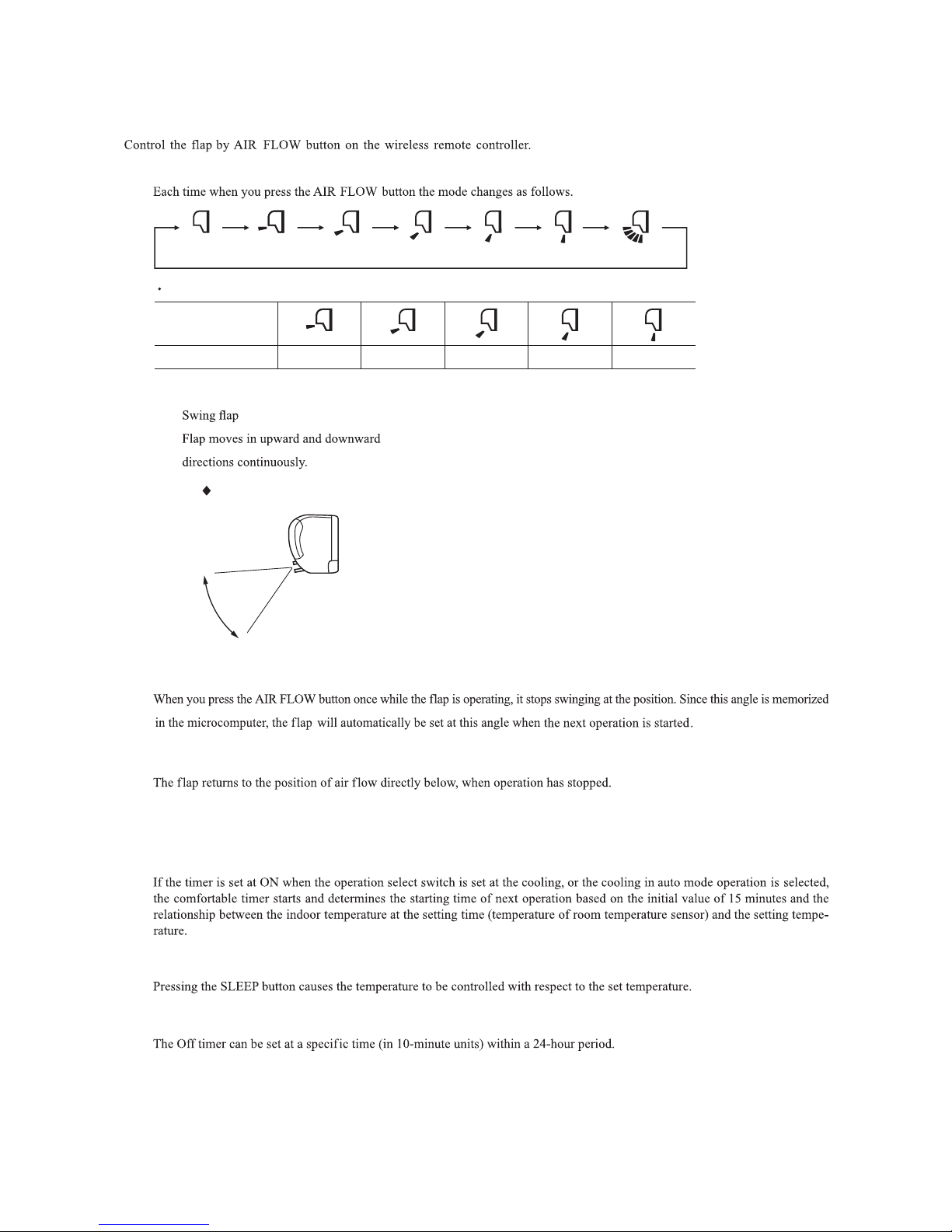
(5)ޓFlap control
(a) Flap
(b) Swing
1)
(c) Memory flap (Flap stopped)
(d) When not operating
COOL , DRY, FAN
Remote controller
display
Approx. 10° Approx. 20° Approx. 30°
(Swing)
(Flap stopped)
Approx. 45° Approx. 60°
Angle of Flap from Horizontal
In COOL, DRY, FAN operation
Approx.
10°
Approx. 60°
(b) Sleep timer operation
(6)ޓTimer operation
(a) Comfortable timer setting (ON timer)
(c) OFF timer operation
-
24
-
27.5
25.5
19.5
18
30
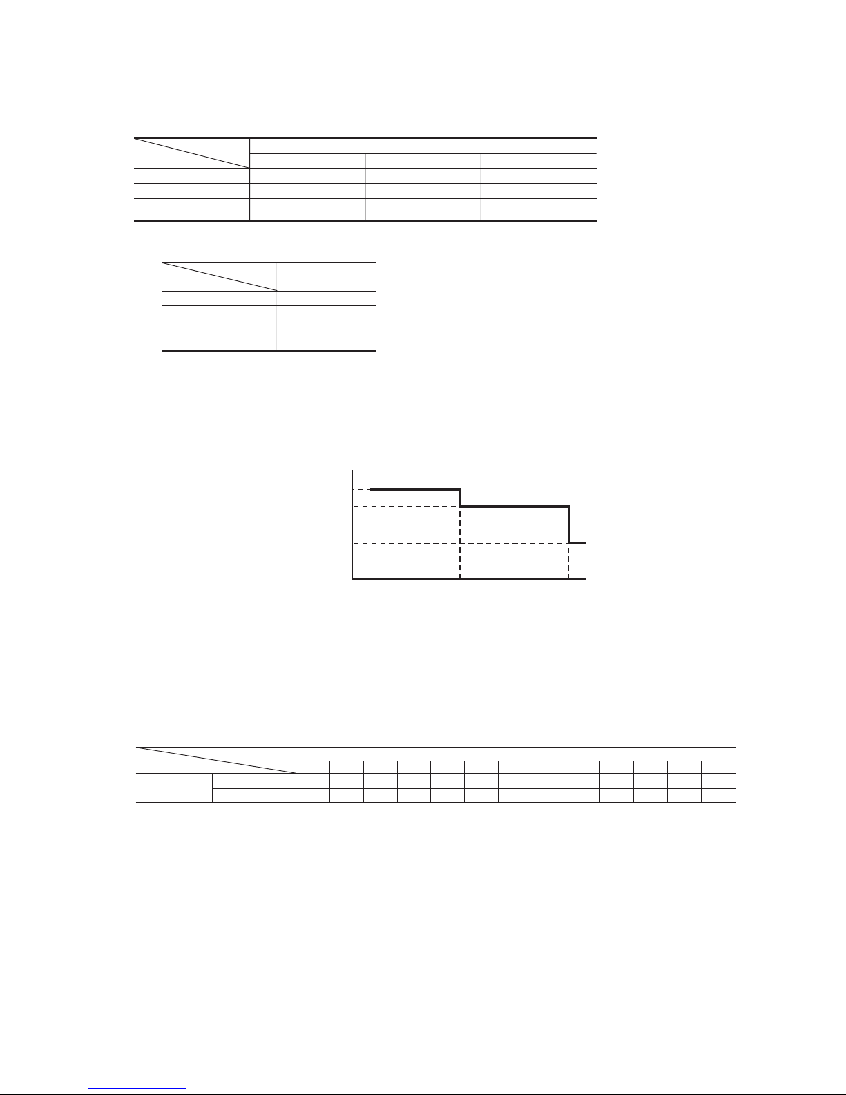
(7) Outline of cooling operation
(a) Operation of major functional components in Cooling mode
(b) Fan speed switching
ON OFF OFF
ON
OFF
(few minutes ON)
OFF
(few minutes ON)
ON ON ON
Thermostat ON Thermostat OFF Failure
Cooling
Compressor
Indoor fan motor
Outdoor fan motor
Auto fan control
Speed 5
Speed 3
Speed 2
Model
Fan speed
All models
Auto
MED
HI
LO
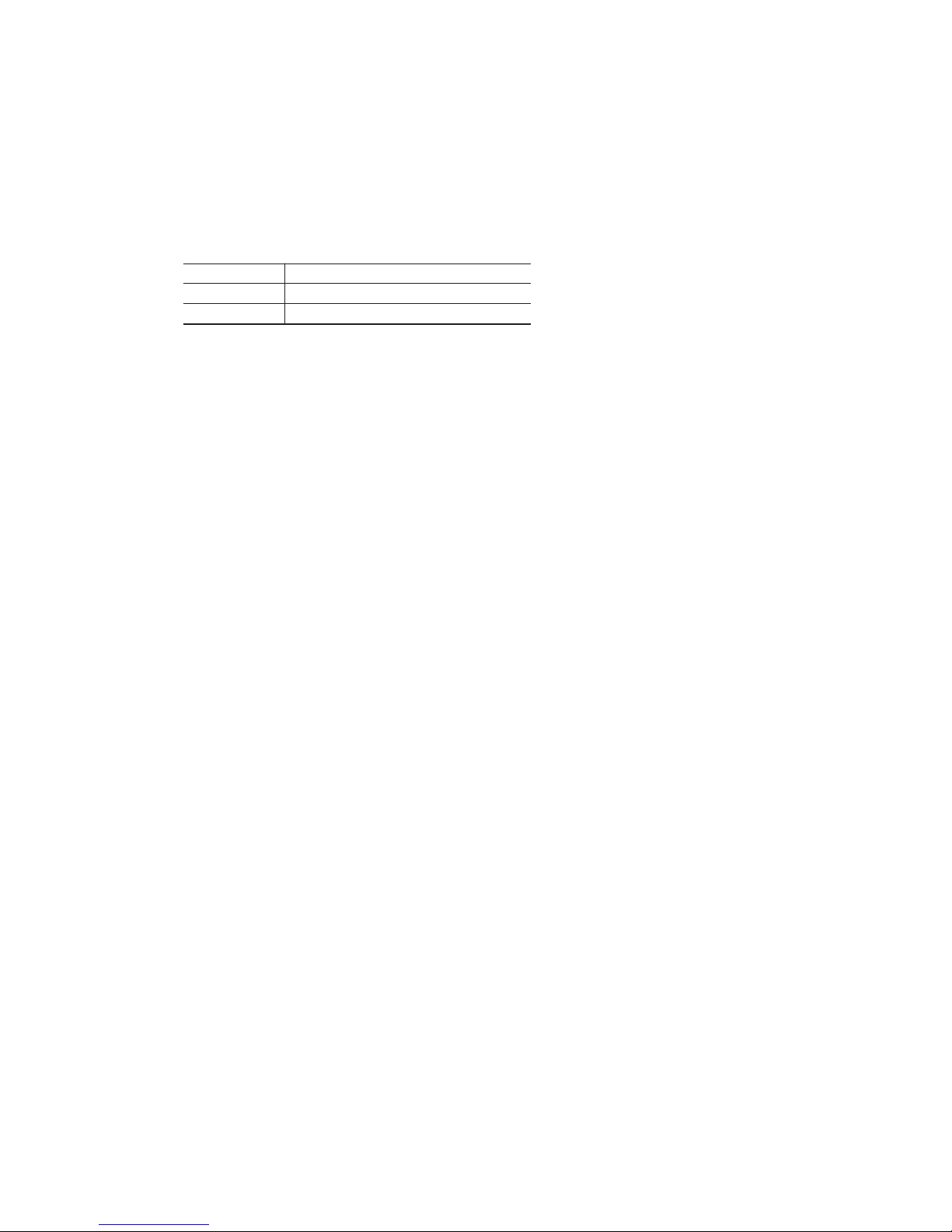
(8) Outline of automatic operation
(a) Determination of operation mode
The unit checks the indoor air temperature and the outdoor air temperature, determines the operation mode, and then begins in
the automatic operation.
Dehumidifying
Cooling
Indoor air temperature (˚C)
Outdoor air temperature (˚C)
(b)
The unit checks the temperature every 30 minutes after the start of operation and, if the result of check is not same as the previ
-
ous operation mode, changes the operation mode.
(c)
When the unit is started again within one hour after the stop of automatic operation or when the automatic operation is selected
during cooling or dehumidifying operation, the unit is operated in the previous operation mode.
(d)
Setting temperature can be adjusted within the following range. There is the relationship as shown below between the signals of
the wireless remote controller and the setting temperature.
Signals of wireless remote controller (Display)
–6 –5 –4 –3 –2 –1
±
0 +1 +2 +3 +4 +5 +6
Setting
Cooling
17 18 19 20 21 22 23 24 25 26 27 28 29
temperature
Dehumidifying
18 19 20 21 22 23 24 25 26 27 28 29 30
-
25
-
(9) Protective control function
(a) Frost prevention for indoor heat exchanger (During cooling or dehumidifying)
1) Operating conditions
a) Indoor heat exchanger temperature (Th2) is lower than 2.5ºC.
b) 3 minutes elapsed after the start of operation.
2) Detail of frost prevention operation
Compressor OFF
Indoor fan Protects the fan tap just before frost prevention control.
Outdoor fan Depending on the stop mode
3) Reset condition: Indoor heat exchanger temperature (Th2) is higher than 8ºC.
(b) Indoor fan motor protection
When the airconditioner is operating and the indoor fan motor is turned ON, if the indoor fan motor has operated at 300 rpm or
under for more than 30 seconds, the unit enters first in the stop mode and then stops the entire system.
TIMER light illuminates simultaneously and the RUN light flashing 6 times at each 8-second.
(c) 3 minutes forced operation
When the compressor begins operating the thermal operation is not effective for 3 minutes, so operation continues as is in the
operation mode. (After 3 minutes has passed the thermal operation is effective.)
However, stopping the compressor via a stop signal or protection control has priority.
(d) Abnormality of outdoor unit
When the indoor heat exchanger temperature does not fall to 25°C or below for 40 minutes after 5 minutes have elapsed since
the compressor operation start, the abnormality stop occurs. (RUN light : ON, TIMER light : 2 time flash)
(e) Sensor disconnection (room temperature, indoor heat exchanger
)
1) Room temperature sensor
If the temperature detected by the room temperature sensor is – 20ºC or lower continuously for 15 seconds or longer while
operation is stopped, an error indication is displayed. (RUN light: 2 time flash, TIMER light: ON)
2) Indoor heat exchanger temperature sensor
If the temperature detected by the indoor heat exchanger temperature sensor is –20ºC or lower continuously for 15 seconds
or longer while operation is stopped, an error indication is displayed.
(RUN light : 1 time flash, TIMER light : ON)

-
26
-
1.8 MAINTENANCE DATA
(1) Cautions
(a) If you are disassembling and checking an air conditioner, be sure to turn off the power before beginning. When working on
indoor units, let the unit sit for about 1 minute after turning off the power before you begin work. When working on an outdoor
unit, there may be an electrical charge applied to the main circuit (electrolytic condenser), so begin work only after discharg-
ing this electrical charge (to DC 10 V or lower).
(b) When taking out printed circuit boards, be sure to do so without exerting force on the circuit boards or package components.
(c) When disconnecting and connecting connectors, take hold of the connector housing and do not pull on the lead wires.
(2) Items to check before troubleshooting
(a) Have you thoroughly investigated the details of the trouble which the customer is complaining about?
(b) Is the air conditioner running? Is it displaying any self-diagnosis information?
(c) Is a power supply with the correct voltage connected?
(d) Are the control lines connecting the indoor and outdoor units wired correctly and connected securely?
(e) Is the outdoor unit’s service valve open?
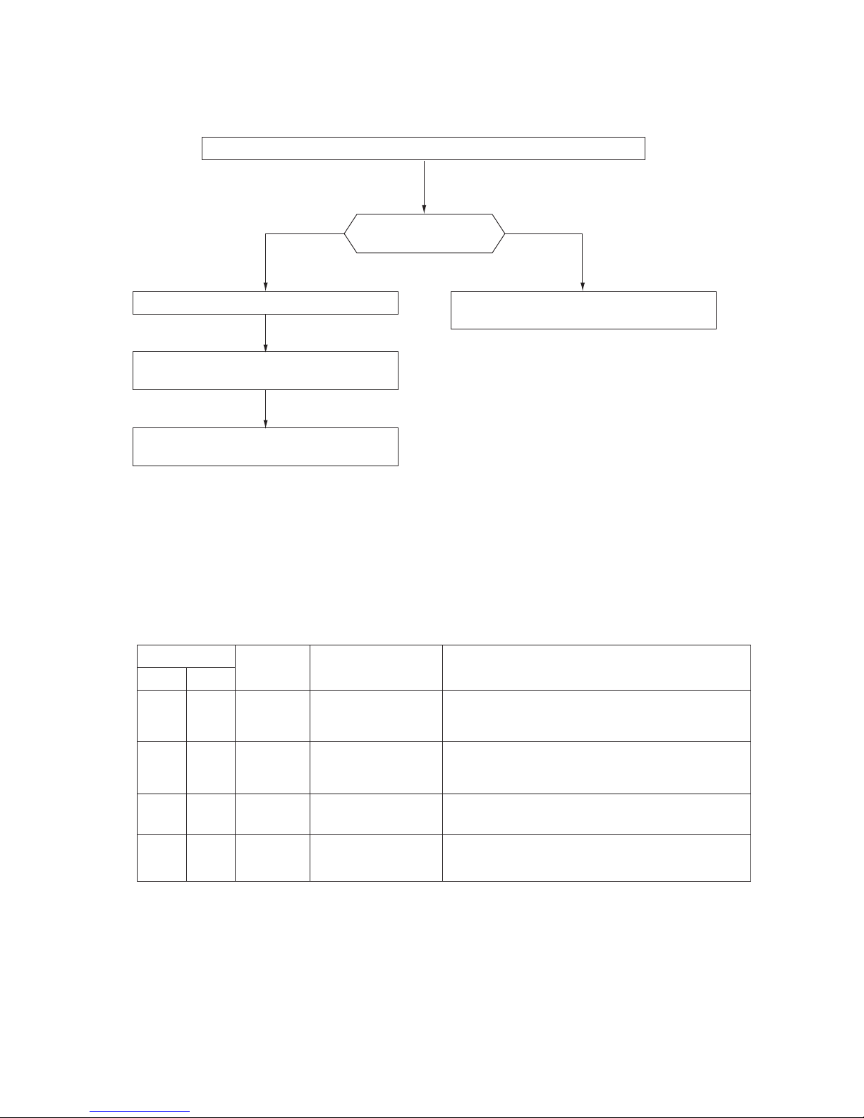
(3) Troubleshooting procedure (If the air conditioner does not run at all)
If the air conditioner does not run at all, diagnose the trouble using the following troubleshooting procedure. If the air condi-
tioner is running but breaks down, proceed to troubleshooting step (4).
Important
When all the following conditions are met, we say that the air conditioner will not run at all.
(a) The RUN light does not light up.
(b) The aps do not open.
(c) The indoor unit fan motors do not run.
(d) The self-diagnosis display does not function.
YES
YES
YES
NO
NO
NO
NO
YES
Troubleshooting procedure (If the air conditioner does not run at all)
Is the cor rec t v olt age
connected for the power
supply?
With the power off, do
the aps open manually,
then close again when
the power is turned on?
Is the r e a re c e pt i o n
sound emitted from the
unit when it is operated
by the remote controller?
Replace the indoor PCB and
perform an operation check.
Make sure the correct voltage is connected, then perform an operation check.
Is the current fuse on the in-
door unit PCB blown?
Proceed to the indoor PCB
check.
Proceed to the wireless remote
controll er trou bl eshooting
procedure.
If the package components
are not damaged, replace
the fuse and perform an operation check again.
* If the voltage is correct, it will be
within the following voltage range.
198 ~ 264 V
-
27
-
(4) Troubleshooting procedure (If the air conditioner runs)
NO
NO
NO
NO
YES
YES
YES
YES
Note (1) Even in cases where only intermittent stop data are generated, the air conditioning system is normal. However, if the same protective operation recurs
repeatedly (3 or more times), it will lead to customer complaints. Judge the conditions in comparison with the contents of the complaints.
Conrm the contents of the customer complaint.
Check the self-diagnosis display.
Eliminate the cause of the trouble and perform an
operation check.
Replace the faulty component, then perform an
operation check.
Identify the faulty component by using the check
procedure corresponding to the content of the trouble.
The cause of the trouble can
be specically identied.
See below.
NO
YES
(5) Self-diagnosis table
When this air conditioner performs an emergency stop, the reason why the emergency stop occurred is displayed by the ashing of
display lights. If the air conditioner is operated using the remote controller 3 minutes or more after the emergency stop, the trouble
display stops and the air conditioner resumes operation.
(1)
Notes (1) The air conditioner cannot be restarted using the remote controller for 3 minutes after operation stops.
When a heat exchanger sensor wire disconnection is detected while operation is
stopped. (If a temperature of –20ºC or lower is detected for 15 seconds, it is
judged that the wire is disconnected.)
(Not displayed during operation.)
When a room temperature sensor wire disconnection is detected while operation
is stopped. (If a temperature of –20ºC or lower is detected for 15 seconds, it is
judged that the wire is disconnected.)
(Not displayed during operation.)
• Broken heat exchanger sensor
wire, poor connector
connection
• Indoor PCB is faulty
• Broken room temperature
sensor wire, poor connector
connection
• Indoor PCB is faulty
When conditions for turning the indoor unit’s fan motor on exist during air
conditioner operation, an indoor unit fan motor speed of 300 rpm or lower is
measured for 30 seconds or longer. (The air conditioner stops.)
• Defective fan motor, poor
connector connection
ON
1 time
flash
ON
2 time
flash
ON
6 time
flash
When there is an emergency stop caused by trouble in the outdoor unit, or the
input current value is found to be lower than the set value.
(The air conditioner stops.)
• Broken compressor wire
• Compressor blockage
2 time
flash
ON
Indoor unit display panel
Cause Display (flashing) condition
RUN
light
TIMER
light
Heat exchanger
sensor error
Room
temperature
sensor error
Indoor fan
motor error
Trouble of
outdoor unit
Description
of trouble
 Loading...