

Mitsubishi Heavy Industries SRK63ZR-S, SRC71ZR-S, SRK80ZR-S, SRC80ZR-S, SRC63ZR-S Technical Manual
...
TECHNICAL MANUAL
-ANUAL.Ogs32+4
INVERTER WALL MOUNTED TYPE
RESIDENTIAL AIR-CONDITIONERS
3PLITSYSTEMAIRTOAIRHEATPUMPTYPE
32+:23
:23
:23

-
1
-
'15 • SRK-T-175
'10 • SRK-T-105
CONTENTS
1. SPECIFICATIONS ........................................................................................ 3
(2) Outdoor units ....................................................................................... 7
..................................................... 19
(3) Remote control
..................................................................................... 10
......................................................................... 6
(1) Indoor units .......................................................................................... 6
2. EXTERIOR DIMENSIONS
3. ELECTRICAL WIRING .............................................................................. 12
(1) Indoor units .......................................................................................... 12
4. NOISE LEVEL ............................................................................................ 14
(2) Outdoor units ....................................................................................... 13
6. RANGE OF USAGE & LIMITATIONS
................................................................................... 21
7. CAPACITY TABLES
5. PIPING SYSTEM ...................................................................................... 17
.................................................................................. 22
8. APPLICATION DATA
9. OUTLINE OF OPERATION CONTROL BY MICROCOMPUTER ............... 34
(10) Timer operation
.................................................................................. 39
(9) 3D auto operation
........................................................................... 38
............................... 35
(1) Operation control function by wireless remote control
(8) Flap and louver control ...................................................................... 37
(5) Selection of the annual cooling function .............................................. 36
(4) Installing two air-conditioners in the same room
......................................................................... 35(3) Auto restart function
(2) Unit ON/OFF button
........................................................................... 35
....................... 34
(11) Silent mode .................................................................................... 39
(13) Installation location setting ........................................................... 40
(12) Night setback .................................................................................. 39
(14) Outline of heating operation ................................................................ 40
(17) Outline of automatic operation ........................................................... 43
(16) Outline of dry (dehumidifying) opertaion ............................................. 42
(15) Outline of cooling operation ............................................................... 42
(18) Protective control function
................................................................... 43
(1) Installation of indoor unit ...................................................................... 22
(2) Installation of outdoor unit .................................................................. 26
(7) Economy operation
.............................................................................. 36
(6) High power operation ........................................................................... 36

-
2
-
'15 • SRK-T-175
'13 • SRK-T-135
(10) How to make sure of wireless remote control ...................................... 69
(12) Outdoor unit inspection points .............................................................. 70
(11) Inspection procedure for blown fuse on the indoor and outdoor PCB .... 69
(8)
Phenomenon observed after shortcircuit, wire breakage on sensor
......... 67
(9) Checking the indoor electrical equipment
........................................... 67
■How to read the model name
Example: SRK 63 Z
Series code
Inveter type
Product capacity (Cooling capacity : 6.3kW)
Model name SRK : Wall mounted type
SRC : Outdoor unit
R-S
........................................................................................... 72
11. OPTION PARTS
....................................................................... 84
12. TECHNICAL INFORMATION
.............................................................. 72
..................................................................... 78
(1) Wired remote control (RC-E5)
(2) Interface kit (SC-BIKN-E)
(3) Superlink E board (SC-ADNA-E) .......................................................... 82
(6) Service mode (Trouble mode access function) ................................... 54
(7) Inspection procedures corresponding to detail of trouble .................... 62
..................... 52
(4) Troubleshooting procedure (If the air-conditioner runs)
(3) Troubleshooting procedure
(If the air-conditioner does not run at all)
........ 51
(2) Items to check before troubleshooting ................................................. 51
(5) Self-diagnosis table ............................................................................. 53
............................................................................... 51
(1) Cautions
............................................................................................. 51
10. MAINTENANCE DATA
-
3
-
'15 • SRK-T-175
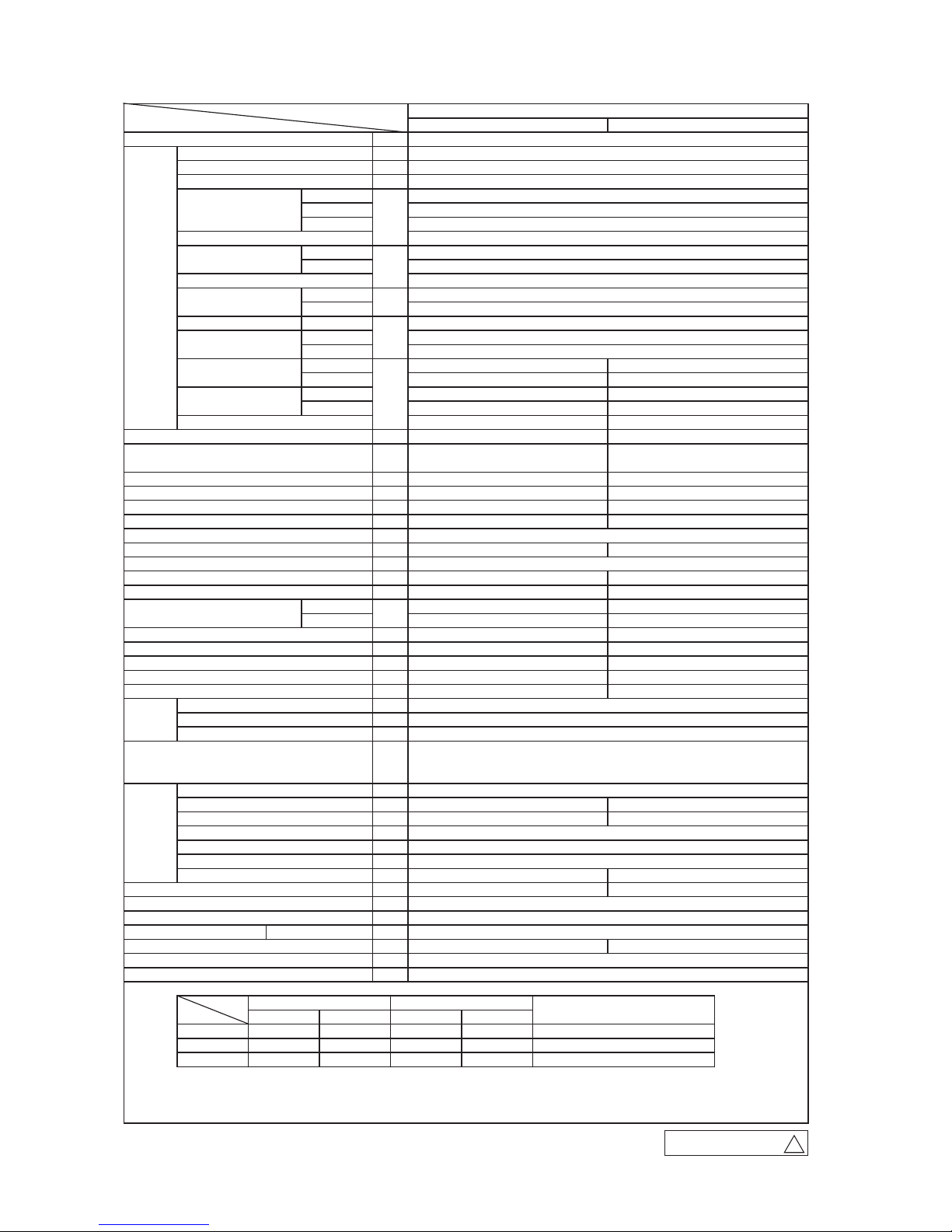
1. SPECIFICATIONS
Model
S-RZ36CRStinuroodtuOS-RZ36KRStinuroodnImetI
Power source 1 Phase, 220 - 240V, 50Hz / 220V, 60Hz
)).xaM(1.7-).niM(2.1(3.6)egnar(yticapacgnilooclanimoN
)).xaM(0.9-).niM(8.0(1.7)egnar(yticapacgnitaehlanimoN
Heating capacity (H2)
)5.2-2.0(58.1gnilooC
)8.2-2.0(47.1gnitaeH
Heating (H2)
9.2noitpmusnocrewopxaM
)V042/032/022(8.7/1.8/5.8gnilooC
gninnuR
)V042/032/022(3.7/6.7/0.8gnitaeH
tnerruc
)V042/032/022(8.7/1.8/5.8tnerrucxam,tnerr
uchsurnI Max. 14.5
99gnilooC
rotcafrewoP
99gnitaeH
14.3gnilooCREE
80.4gnitaeH
Heating (H2)
Cooling 59 67
Heating 60 66
4552:oLU53:oL93:eM44:iHgnilooC
4582:oLU43:oL83:eM44:iHgnitaeH
54:gnitaeH/54:gnilooClevelerusserpdnuosedomtneliS
Exterior dimensions (Height x Width x Depth) 339 x 1197 x 262 640 x 800(+71) x 290
etihwoccutSwonseniFecnaraepparoiretxE
tnelaviuqeraen)1.1/5.7Y2.4(tnelaviuqeraen)1.0/3.9Y0.8()rolocllesnuM(
Net weight 5.745.51
1x)epytyratorniwT(2ECM3115TMRyt'Q&ep
ytrosserpmoC
)nevirdretrevnI(04.1)dohtemgnitratS(rotomrosserpmoC
)86AMEZEERFDNOMAID(54.0)epyt,tnuomA(liotnaregirfeR
Refrigerant (Type, amount, pre-charge length) R410A 1.55 in outdoor unit (incl. the amount for the piping of 15m )
Heat exchanger
Louver fins & inner grooved tubing
M fins & inner grooved tubing
evlavnoisnapxecinortcelE+sebutyrallipaClortnoctnaregirfeR
1xnafrelleporP1xnaflaitnegnaTyt'Q&epytnaF
)evirdtceriD(1x43)evirdtceriD(1x65)dohtemgnitratS(rotomnaF
Cooling Hi: 20.5 Me: 18.1 Lo: 15.7 ULo: 10.4 41.5
Heating Hi: 23.5 Me: 19.0 Lo: 16.5 ULo: 13.1 41.5
00erusserpcitatslanretxeelbaliavA
elbissoptoNekatniriaedistuO
2x)el
bahsaw(tenenelyporpyloPytitnauQ/ytilauQ,retlifriA
)rotomnafrof(eveelsrebbuRrebrosbanoitarbiv&kcohS
Rubber sleeve (for fan motor & compressor)
retaehcirtcelE
lortnocetomersseleriWlortnocetomeR
tatsomrehtretupmocorciMlortnocerutarepmetmooR
Operation display RUN: Green , TIMER: Yellow , HI POWER: Green ,3D AUTO: Green
Compressor overheat protection, Overcurrent protection,
Safety equipments
Frost protection, Serial signal error protection, Indoor fan motor error protection,
Heating overload protection( High pressure control ), Cooling overload protection
:enildiuqiL)D.O(ezisgnipiptnaregirfeR
φ
6.35 ( 1/4" ) Gas line: φ12.7 ( 1/2" )
noitcennoceralFnoitcennoceralFdohtemgnitcennoC
Attached length of piping Liquid line : 0.78 / Gas line : 0.71
ー
ーー
ー
ー
tnednepedni,)sedishtoB(yrasseceNgnipiprofnoitalusnI
03.xaMhtgnel)yawe
no(eniltnaregirfeR
Vertical height diff. between O.U. and I.U.
Max.20 ( Outdoor unit is higher ) / Max.20 ( Outdoor unit is lower )
seloH)61PV(elbatcennocesoHesohniarD φ20 x 5 pcs
ー ー
thgiehtfilxam,pmupniarD
61ezisrekaerbdednemmoceR
)V042/032/022(8.7/1.8/5.8)erepmarotordekcoL(.A.R.L
Interconnecting wires Size x Core number 1.5mm
2
x 4 cores ( Including earth cable ) / Terminal block ( Screw fixing type )
4XPI0XPIrebmunPI
Standard accessories
Mounting kit, Clean filter ( Allergen clear filter x 1, Photocatalytic washable deodorizing filter x 1 )
)E-NKIB-CS(tikecafretnIstrapnoitpO
Note (1) The data are measured at the following conditions. The pipe length is 5m.
Item
Indoor air temperature Outdoor air temperature
Operation
DB WB
Cooling
27℃ 19℃ 35℃ 24℃
Heating
20℃ 7℃ 6℃
Heating (H2)
20℃ 2℃ 1℃
(2) This air-conditioner is manufactured and tested in conformity with the ISO.
(3) Sound level indicates the value in an anechoic chamber. During operation these values are somewhat
higher due to ambient conditions.
(4) Select the breaker size according to the own national standard.
-
A
ℓ
kg
SRK63ZR-S
Operation
data
kW
kW
kW
-
Power consumption
kW
W
%
COP
-
Sound power level
dB(A)
Sound pressure level
mm
kg
kW
Installation
data
mm
m
m
m
Air flow
m3/min
Pa
Operation
control
ISO5151-H2
mm
A
A
Standards
ISO5151-T1
ISO5151-H1
ー
ー
ー
ー
ー
ー
DBWB
RWA000Z262
A
-
4
-
'15 • SRK-T-175
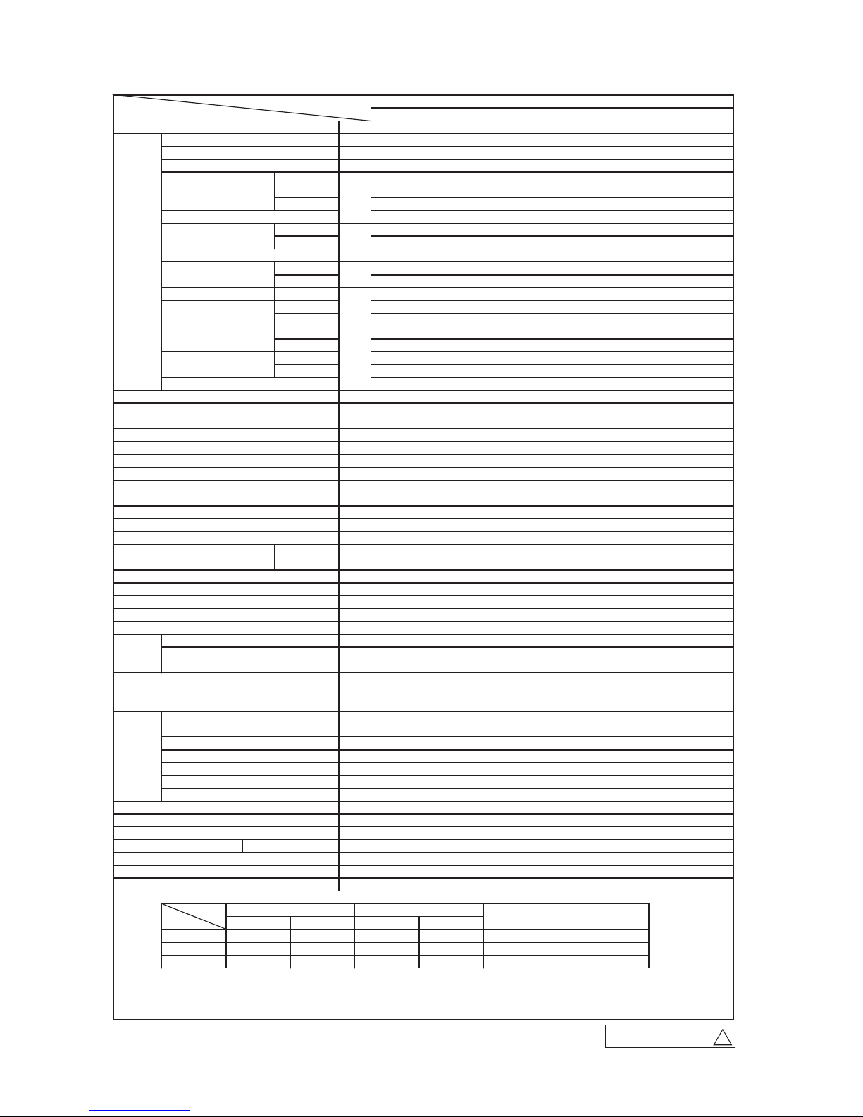
Model
S-RZ17CRStinuroodtuOS-RZ17KRStinuroodnImetI
Power source 1 Phase, 220 - 240V, 50Hz / 220V, 60Hz
)).xaM(7.7-).niM(3.2(1.7)egnar(yticapacgnilooclanimoN
)).xaM(0.01-).niM(0.2(0.8)egnar(yticapacgnitaehlanimoN
Heating capacity (H2)
)7.2-5.0(50.2gnilooC
)4.3-4.0(60.2gnitaeH
Heating (H2)
56.3noitpmusnocrewopxaM
)V042/032/022(7.8/1.9/5.9gnilooC
gninnuR
)V042/032/022(8.8/1.9/6.9gnitaeH
tnerruc
)V042/032/022(8.8/1.9/6.9tnerrucxam,tner
ruchsurnI Max. 17
89gnilooC
rotcafrewoP
89gnitaeH
64.3gnilooCREE
88.3gnitaeH
Heating (H2)
Cooling 58 65
Heating 60 63
3552:oLU73:oL14:eM44:iHgnilooC
1582:oLU53:oL93:eM64:iHgnitaeH
:gnitaeH/54:gnilooClevelerusserpdnuosedomtneliS 41
Exterior dimensions (Height x Width x Depth) 339 x 1197 x 262 750 x 880(+88) x 340
etihwoccutSwonseniFecnaraepparoiretxE
tnelaviuqeraen)1.1/5.7Y2.4(tnelaviuqeraen)1.0/3.9Y0.8()rolocllesnuM(
Net weight 755.51
1x)epytyratorniwT(2EDM8115TMRyt'Q&epyt
rosserpmoC
)nevirdretrevnI(04.1)dohtemgnitratS(rotomrosserpmoC
)86AMEZEERFDNOMAID(576.0)epyt,tnuomA(liotnaregirfeR
Refrigerant (Type, amount, pre-charge length) R410A 1.8 in outdoor unit (incl. the amount for the piping of 15m )
Heat exchanger
Louver fins & inner grooved tubing
M fins & inner grooved tubing
evlavnoisnapxecinortcelE+sebutyrallipaClortnoctnaregirfeR
1xnafrelleporP1xnaflaitnegnaTyt'Q&epytnaF
)evirdtceriD(1x68)evirdtceriD(1x65)dohtemgnitratS(rotomnaF
Cooling Hi: 20.5 Me: 18.6 Lo: 16.2 ULo: 10.4 55
Heating Hi: 25.5 Me: 19.8 Lo: 17.3 ULo: 13.3 43.5
00erusserpcitatslanretxeelbaliavA
elbissoptoNekatniriaedistuO
2x)elba
hsaw(tenenelyporpyloPytitnauQ/ytilauQ,retlifriA
)rotomnafrof(eveelsrebbuRrebrosbanoitarbiv&kcohS
Rubber sleeve (for fan motor & compressor)
retaehcirtcelE
lortnocetomersseleriWlortnocetomeR
tatsomrehtretupmocorciMlortnocerutarepmetmooR
Operation display RUN: Green , TIMER: Yellow , HI POWER: Green ,3D AUTO: Green
Compressor overheat protection, Overcurrent protection,
Safety equipments
Frost protection, Serial signal error protection, Indoor fan motor error protection,
Heating overload protection( High pressure control ), Cooling overload protection
:enildiuqiL)D.O(ezisgnipiptnaregirfeR φ6.35 ( 1/4" ) Gas line: φ15.88 ( 5/8" )
noitcennoceralFnoitcennoceralFdohtemgnitcennoC
Attached length of piping Liquid line : 0.78 / Gas line : 0.72
tnednepedni,)sedishtoB(yrasseceNgnipiprofnoitalusnI
03.xaMhtgnel)yaweno(eni
ltnaregirfeR
Vertical height diff. between O.U. and I.U.
Max.20 ( Outdoor unit is higher ) / Max.20 ( Outdoor unit is lower )
seloH)61PV(elbatcennocesoHesohniarD φ20 x 3 pcs
ー
thgiehtfilxam,pmupniarD
02ezisrekaerbdednemmoceR
)V042/032/022(8.8/1.9/6.9)erepmarotordekcoL(.A.R.L
Interconnecting wires Size x Core number 1.5mm
2
x 4 cores ( Including earth cable ) / Terminal block ( Screw fixing type )
4XPI0XPIrebmunPI
Standard accessories
Mounting kit, Clean filter ( Allergen clear filter x 1, Photocatalytic washable deodorizing filter x 1 )
)E-NKIB-CS(tikecafretnIstrapnoitpO
Note (1) The data are measured at the following conditions. The pipe length is 5m.
Item
Indoor air temperature Outdoor air temperature
Operation
DB WB
Cooling
27℃ 19℃ 35℃ 24℃
Heating
20℃ 7℃ 6℃
Heating (H2)
20℃ 2℃ 1℃
(2) This air-conditioner is manufactured and tested in conformity with the ISO.
(3) Sound level indicates the value in an anechoic chamber. During operation these values are somewhat
higher due to ambient conditions.
(4) Select the breaker size according to the own national standard.
ISO5151-H2
mm
A
A
Standards
ISO5151-T1
ISO5151-H1
Pa
Operation
control
Installation
data
mm
m
m
m
ℓ
kg
Air flow
m3/min
W
%
COP
-
Sound power level
dB(A)
Sound pressure level
mm
kg
kW
SRK71ZR-S
Operation
data
kW
kW
kW
-
Power consumption
kW
-
A
ー
ー
ー
ー
ー
ー
ー
ー
ー
ー
ー
ー
WB DB
RWA000Z262
A
-
5
-
'15 • SRK-T-175
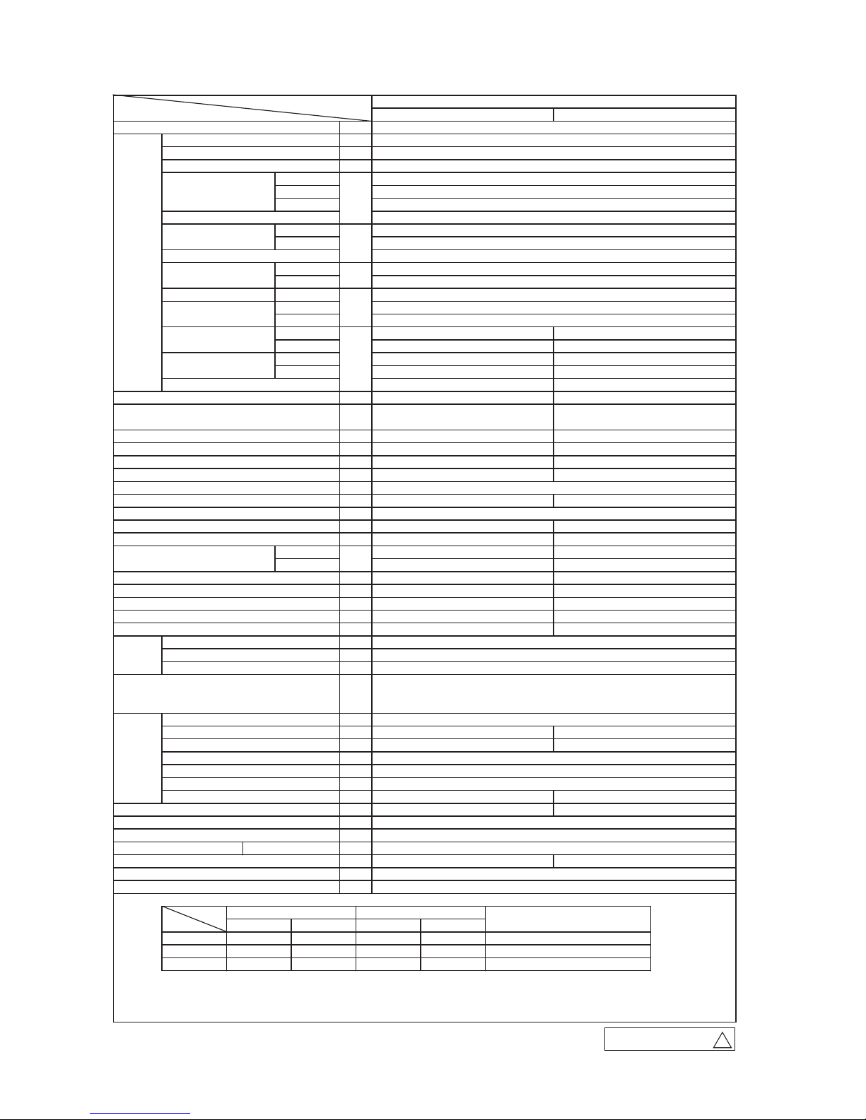
Model
S-RZ08CRStinuroodtuOS-RZ08KRStinuroodnImetI
Power source 1 Phase, 220 - 240V, 50Hz / 220V, 60Hz
)).xaM(0.9-).niM(3.2(0.8)egnar(yticapacgnilooclanimoN
)).xaM(5.01-).niM(1.2(0.9)egnar(yticapacgnitaehlanimoN
Heating capacity (H2)
)2.3-5.0(53.2gnilooC
)5.3-4.0(04.2gnitaeH
Heating (H2)
56.3noitpmusnocrewopxaM
)V042/032/022(0.01/4.01/9.01gnilooC
gninnuR
)V042/032/022(2.01/6.01/1.11gnitaeH
tnerruc
)V042/032/022(2.01/6.01/1.11tnerruc
xam,tnerruchsurnI Max. 17
89gnilooC
rotcafrewoP
89gnitaeH
04.3gnilooCREE
57.3gnitaeH
Heating (H2)
8626gnilooC
7626gnitaeH
6562:oLU93:oL44:eM74:iHgnilooC
5592:oLU63:oL14:eM74:iHgnitaeH
:gnitaeH/74:gnilooClevelerusserpdnuosedomtneliS 42
Exterior dimensions (Height x Width x Depth) 339 x 1197 x 262 750 x 880(+88) x 340
etihwoccutSwonseniFecnaraepparoiretxE
tnelaviuqeraen)1.1/5.7Y2.4(tnelaviuqeraen)1.0/3.9Y0.8()rolocllesnuM(
Net weight 5.855.61
1x)epytyratorniw
T(2EDM8115TMRyt'Q&epytrosserpmoC
)nevirdretrevnI(04.1)dohtemgnitratS(rotomrosserpmoC
)86AMEZEERFDNOMAID(576.0)epyt,tnuomA(liotnaregirfeR
Refrigerant (Type, amount, pre-charge length) R410A 1.9 in outdoor unit (incl. the amount for the piping of 15m )
Heat exchanger
Louver fins & inner grooved tubing
M fins & inner grooved tubing
evlavnoisnapxecinortcelE+sebutyrallipaClortnoctnaregirfeR
1xnafrelleporP1xnaflaitnegnaTyt'Q&epytnaF
)evirdtceriD(1x68)evirdtceriD(1x65)dohtemgnitratS(rotomnaF
Cooling Hi: 23.5 Me: 20.2 Lo: 17.5 ULo: 10.4 63
Heating Hi: 26.5 Me: 21.3 Lo: 18.4 ULo: 13.5 49.5
00erusserpcitatslanretxeelbaliavA
elbissoptoNek
atniriaedistuO
2x)elbahsaw(tenenelyporpyloPytitnauQ/ytilauQ,retlifriA
)rotomnafrof(eveelsrebbuRrebrosbanoitarbiv&kcohS
Rubber sleeve (for fan motor & compressor)
retaehcirtcelE
lortnocetomersseleriWlortnocetomeR
tatsomrehtretupmocorciMlortnocerutarepmetmooR
Operation display RUN: Green , TIMER: Yellow , HI POWER: Green ,3D AUTO: Green
Compressor overheat protection, Overcurrent protection,
Safety equipments
Frost protection, Serial signal error protection, Indoor fan motor error protection,
Heating overload protection( High pressure control ), Cooling overload protection
:enildiuqiL)D.O(ezisgnipiptnaregirfeR φ6.35 ( 1/4" ) Gas line: φ15.88 ( 5/8" )
noitcennoceralFnoitcennoceralFdohtemgnitcennoC
Attached length of piping Liquid line : 0.78 / Gas line : 0.72
tnednepedni,)sedishtoB(yrasseceNgnipiprofnoitalusnI
03.xaMhtgnel)yaweno(eniltnaregirfeR
Vertical height diff. between O.U. and I.U.
Max.20 ( Outdoor unit is higher ) / Max.20 ( Outdoor unit is lower )
seloH)61PV(elbatcennocesoHesohniarD φ20 x 3 pcs
thgiehtfilxam,pmupniarD
02ezisrekaerbdednemmoceR
)V042/032/022(2.01/6.01/1.11)erepmarotordekcoL(.A.R.L
Interconnecting wires Size x Core number 1.5mm
2
x 4 cores ( Including earth cable ) / Terminal block ( Screw fixing type )
4XPI0XPIrebmunPI
Standard accessories
Mounting kit, Clean filter ( Allergen clear filter x 1, Photocatalytic washable deodorizing filter x 1 )
)E-NKIB-CS(tikecafretnIstrapnoitpO
Note (1) The data are measured at the following conditions. The pipe length is 5m.
Item
Indoor air temperature Outdoor air temperature
Operation
DB WB
Cooling
27℃ 19℃ 35℃ 24℃
Heating
20℃ 7℃ 6℃
Heating (H2)
20℃ 2℃ 1℃
(2) This air-conditioner is manufactured and tested in conformity with the ISO.
(3) Sound level indicates the value in an anechoic chamber. During operation these values are somewhat
higher due to ambient conditions.
(4) Select the breaker size according to the own national standard.
ISO5151-H2
mm
A
A
Standards
ISO5151-T1
ISO5151-H1
Pa
Operation
control
Installation
data
mm
m
m
m
ℓ
kg
Air flow
m3/min
W
%
COP
-
Sound power level
dB(A)
Sound pressure level
mm
kg
kW
SRK80ZR-S
Operation
data
kW
kW
kW
-
Power consumption
kW
-
A
ー
ー
ーー
ー
ー
ー
ー
ー
ー
ー
ー
ー
WB DB
RWA000Z262
A
-
6
-
'15 • SRK-T-175
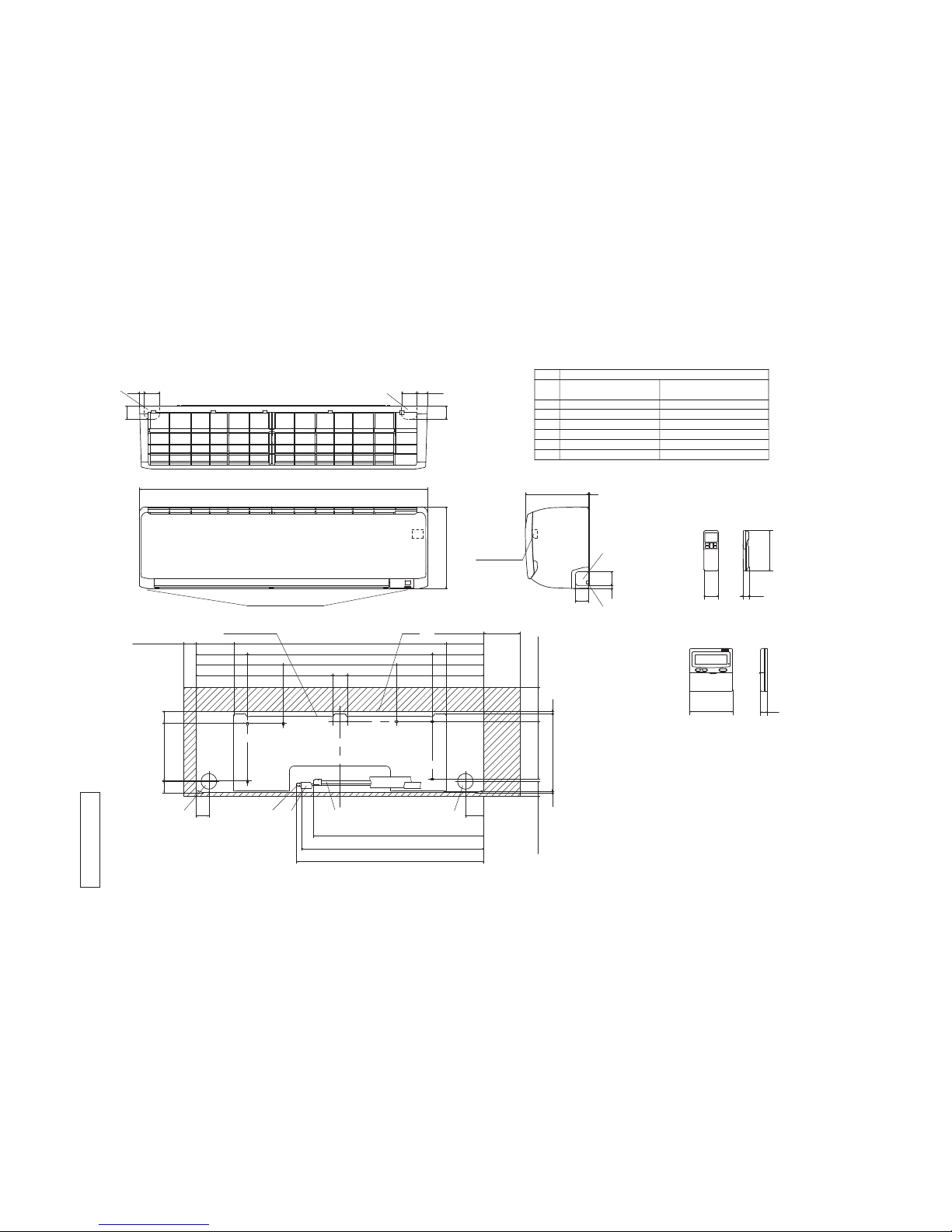
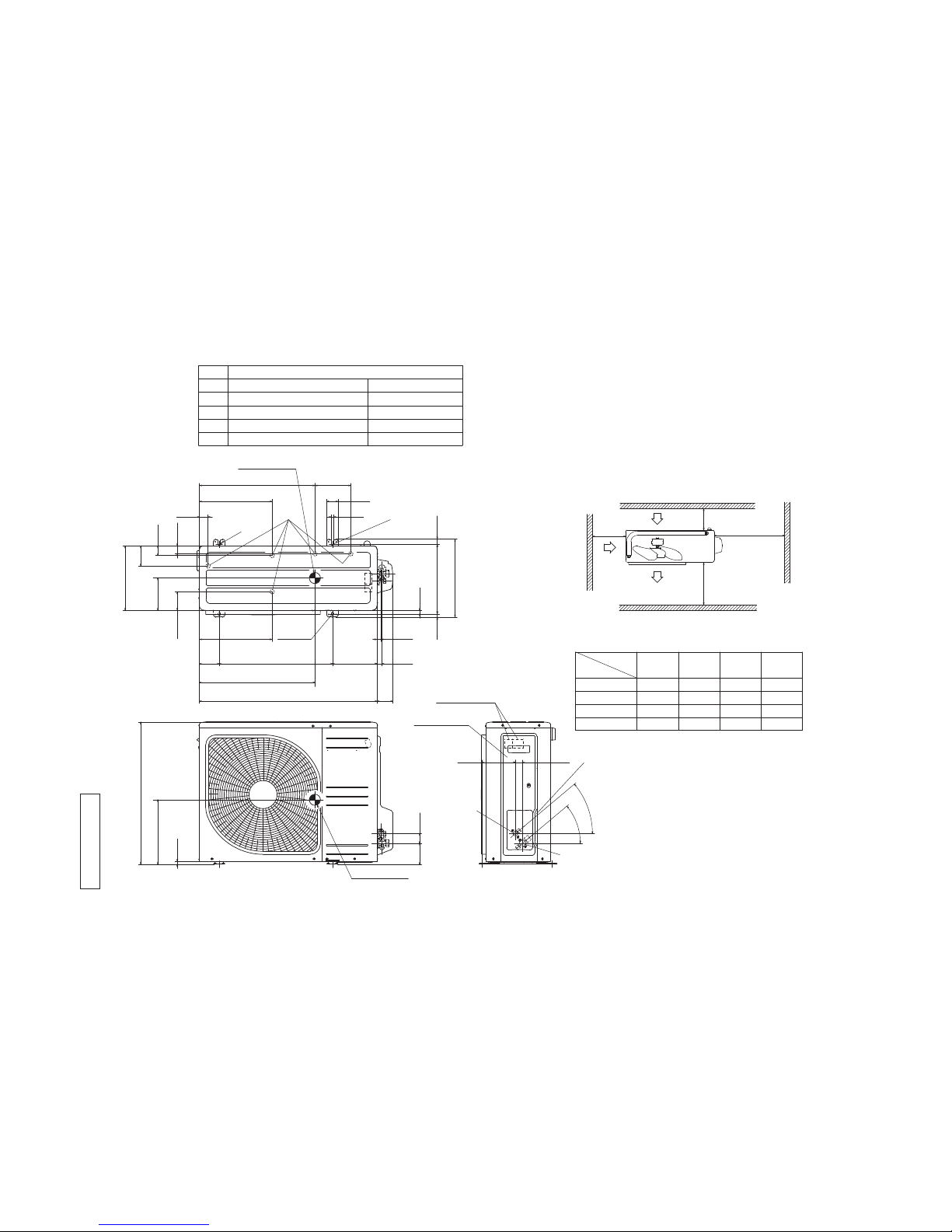
2. EXTERIOR DIMENSIONS
(1) Indoor units
Models SRK63ZR-S, 71ZR-S, 80ZR-S
RLD000Z002
Ƒ
Hole on wall for right rear piping
Hole on wall for left rear piping
Gas piping
Outlet for wiring(on both side)
Drain hose
Liquid piping
F
E
C
D
B
Symbol
A
(䃥65)
93
Content
(䃥65)
Outlet for piping(on both side)
G
SRK63 䃥(/)(Flare)
Wireless remote control
65.䃥(5/)(Flare)
Wired remote control
(Option)
䃥(/)(Flare)
(Service space)
Unit
Space for installation and service when viewing from the front
3
55
53
55
(Service space)
(Service space)
(Service space)
(
65.,:
)
55
Installation plate
Unit:mm
Note()The model name label is attached
RQWKHXQGHUVLGHRIWKHLQGRRUXQLW
Outlet for down piping
(Refer to the above view)
Terminal block
D E CAB
G
G
G
F
-
7
-
'15 • SRK-T-175
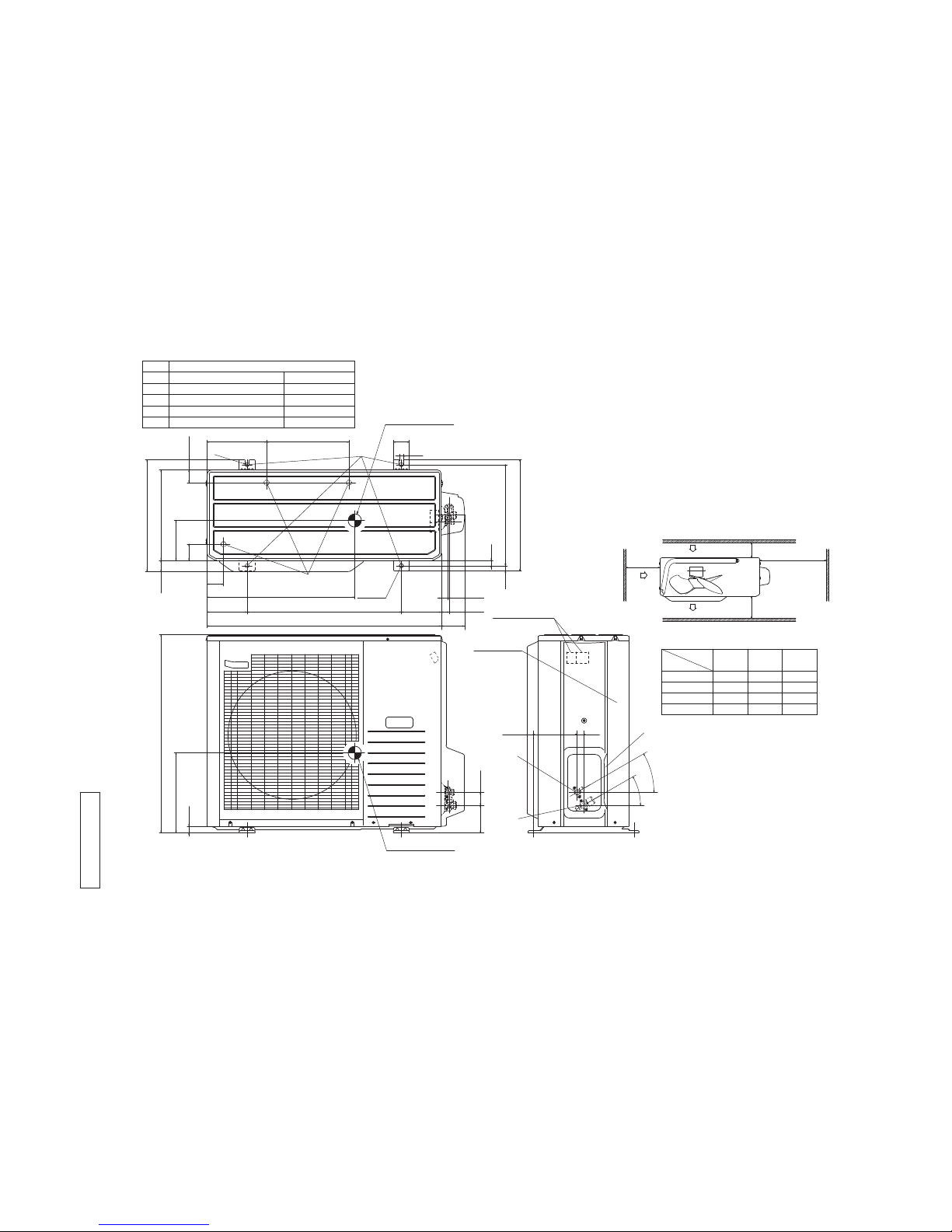
(2) Outdoor units
Model SRC63ZR-S
RCT000Z016
Unit:mm
290 145
520
φ12.7(1/2")(Flare)
Content
C Pipe/cable draw-out hole
D
E Anchor bolt hole
Drain discharge hole
Symbol
B
A Service valve connection(gas side)
M10×4 places
φ20×5 places
Service valve connection(liquid side)
φ6.35(1/4")(Flare)
L2
Air
intake
Air outlet
Air intake
L3
L1
Minimum installation space
(Service space
for electrical
parts)
L4
L2
L3
L4
L1
100
100
250
Open
I Ⅱ
Open
250
80
280
Ⅲ
280
Open
80
75
Examples of
Dimensions
installation
Ⅵ
180
Open
80
Open
Terminal block
The height of a wall is 1200mm or less
Service panel
Slot hole
Notes
(1) It must not be surrounded by walls on four sides.
(2)The unit must be fixed with anchor bolts. An anchor bolt
must not protrude more than 15mm.
(3) Where the unit is subjected to strong winds, lay it in such a
direction that the blower outlet face is perpendicular to the
dominant wind direction.
(4) Leave 1m or more space above the unit.
(5) A wall in front of the blower outlet must not exceed the unit's height.
(6)The model name label is attached on the service panel.
Center of gravity
Center of gravity
94.5 42.5
640
800
89 510 201
327.3
83.5
290
43.5
327.3 50.6
12
24.3312.514.8
71
17.9
40°
40°
33.5148.4
12.4
351.6
38.6
90.6
520.6 161
35.6
21.9
2-12X16
2-R
16.4
A
C
B
D
E
-
8
-
'15 • SRK-T-175
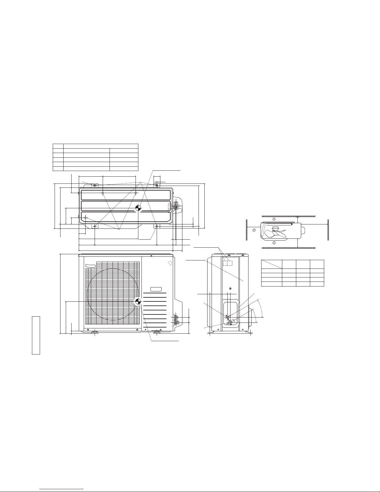
Model SRC71ZR-S
15
60
38019
418
880
150 580 150
27
340
223 310
61
6124
750
20
30
2-R
42.6
47.5
421.6
300 150
555
Unit:mm
Rear panel
87.9
103.3 48.5
165.5 25
30°
30°
2-φ15
Terminal block
The height of a wall is 1200mm or less
Notes
(1)It must not be surrounded by walls on four sides.
(2)The unit must be fixed with anchor bolts. An anchor bolt
must not protrude more than 15mm.
(3)Where the unit is subjected to strong winds, lay it in such a
direction that the blower outlet face is perpendicular to the
dominant wind direction.
(4)Leave 1m or more space above the unit.
(5)A wall in front of the blower outlet must not exceed the
unit's height.
(6)The model name label is attached on the rear panel.
Air intake
Air intake
Air outlet
(Service space
for electrical
parts)
Symbol Content
A Service valve connection(gas side) φ15.88(5/8")(Flare)
B Service valve connection(liquid side) φ6.35(1/4")(Flare)
C Pipe/cable draw-out hole
D Drain discharge hole φ20 x 3 places
E Anchor bolt hole M10 x 4 places
Minimum installation space
L2
L4
L1
L3
Center of gravity
Center of gravity
L2
L3
L4
L1
300
100
250
Open
Ⅰ Ⅱ
Open
250
100
500
Ⅲ
Open
250
150
250
Examples of
Dimensions
installation
D
E
B
A
C
RCR000Z024
-
9
-
'15 • SRK-T-175
Model SRC80ZR-S
15
60
38019
418
880
150 580 150
27
340
223 310
61
6124
750
20
30
2-R
42.6
47.5
421.6
300 150
555
Unit:mm
87.9
103.3 48.5
165.5 25
2-
φ
15
Terminal block
30°
30°
The height of a wall is 1200mm or less
Rear panel
Notes
(1)It must not be surrounded by walls on four sides.
(2)The unit must be fixed with anchor bolts. An anchor bolt
must not protrude more than 15mm.
(3)Where the unit is subjected to strong winds, lay it in such a
direction that the blower outlet face is perpendicular to the
dominant wind direction.
(4)Leave 1m or more space above the unit.
(5)A wall in front of the blower outlet must not exceed the
unit's height.
(6)The model name label is attached on the rear panel.
Air intake
Air intake
Air outlet
(Service space
for electrical
parts)
Symbol Content
A Service valve connection(gas side) φ15.88(5/8")(Flare)
B Service valve connection(liquid side) φ6.35(1/4")(Flare)
C Pipe/cable draw-out hole
D Drain discharge hole φ20 x 3 places
E Anchor bolt hole M10 x 4 places
Minimum installation space
L2
L4
L1
L3
Center of gravity
Center of gravity
L2
L3
L4
L1
300
100
250
Open
Ⅰ Ⅱ
Open
250
100
500
Ⅲ
Open
250
150
250
Examples of
Dimensions
installation
D
E
B
A
C
RCR000Z025
-
10
-
'15 • SRK-T-175
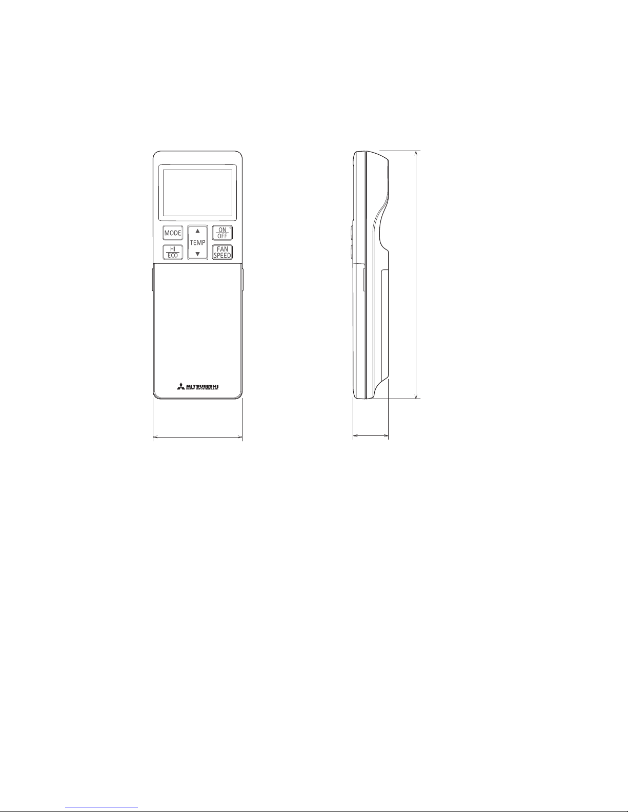
(3) Remote control
(a) Wireless remote control
Unit : mm
60
26
167
-
11
-
'15 • SRK-T-175
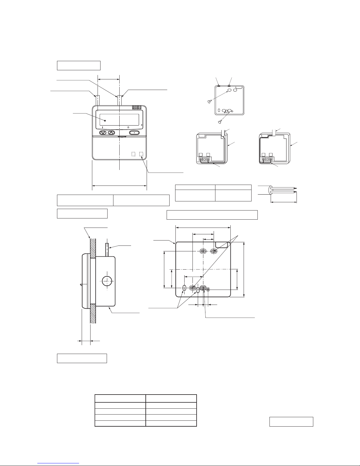
(b) Wired remote control (option parts)
Interface kit (SC-BIKN-E) is required to use the wired remote control.
PJZ000Z295
TEMP ON/OFF
48
□120
L C D
Wall surface
Wiring
Electrical box
(Not included)
19
Wiring specifications
Exposed mounting
23
46
11.5 11
Remote
control
outline
120
45
83.5
42
120
Remote control installation dimensions
Wiring oulet
Installation hole
12×7 Slot hole
9.5×5 Slot hole (4places)
(1) Installation screw for remote control
M4 Screw (2 pieces)
44
(1) If the prolongation is over 100m, change to the size below.
But, wiring in the remote control case should be under 0.5mm2. Change the wire size outside of
the case according to wire connecting. Waterproof treatment is necessary at the wire connecting
section. Be careful about contact failure.
Length Wiring thickness
100 to 200m
0.5mm2×2 cores
0.75mm2×2 cores
1.25mm2×2 cores
2.0mm2×2 cores
Under 300m
Under 400m
Under 600m
Upper part
Lower part
Lower case
Sheath
Upper cace
Board
Wiring
Upper
Lower
X Y
Sheath
Upper cace
Board
Wiring
Upper
Lower
YX
Tighten the screws after
cutting off the thin part of
screw mounting part.
Embedded mounting
Pearl WhiteExterior appearance
(Munsell color) (N8.5) near equivalent
The peeling-off length of sheath
The peeling-off length
of sheath
In case of pulling out from
upper left
In case of pulling out
from upper left
In case of pulling out
from upper left
X wiring : 170mm
Y wiring : 190mm
Pulling out from center
X wiring : 215mm
Y wiring : 195mm
Pulling out from upper left
In case of pulling out from center
In case of pulling out
from center
In case of pulling out
from center
Wiring outlet
Cut off the upper thin part of remote control lower case with a nipper or knife,
and grind burrs with a file etc.
0.3mm2×2 cores.
X, Y Terminal block
Attach M3 screw
with washer
Unit:mm
-
12
-
'15 • SRK-T-175
3. ELECTRICAL WIRING
(1) Indoor units
Models SRK63ZR-S, 71ZR-S, 80ZR-S
RWA000Z406
t
o
t
o
t
o
TO OUTDOOR UNIT
POWER WIRES
SIGNAL WIRE
1
2/N
3
POWER SOURCE
1 Phase 220-240V 50Hz
220V 60Hz
F 3.15A
F
G
S/N
Va
FM
CNU
CNS
INTERFACE KIT
J
U
M
HEAT
1
3
4
5
6
5
TB
1
2/N
3
EXCHANGER
L
HEAT
EXCHANGER
BOARD
CIRCUIT
PRINTED
SM
1
LM
1
CNX
M
M
M
5
5
LM
2
RD
WH
RD
WH
BK
BL
Y
Y/G
BK
CNG
CNE
DISPLAY
WIRELESS RECEIVER
CNF
BACK-UP SW
2
8
Th2
1
Th2
2
Th1
Th3
CNY
Y/G
CNM
5
Color Marks
Blue
BlackBK
Red
BL
RD
WhiteWH
Yellow/GreenY/G
YellowY
ColorMark
Heat exchanger sensor
Humidity sensor
Fan motor
Room temp. sensor
Flap motor
Th1
Th2
1,2
Th3
Diode stackDS
FuseF
ConnectorCNE
FM
I
Terminal blockTB
Louver motor
LM
1,2
SM
1
Description
Item
VaristorVa
CNF
CNG
CNM
CNS
CNU
CNX
CNY
L 250V
1
DS
-
13
-
'15 • SRK-T-175
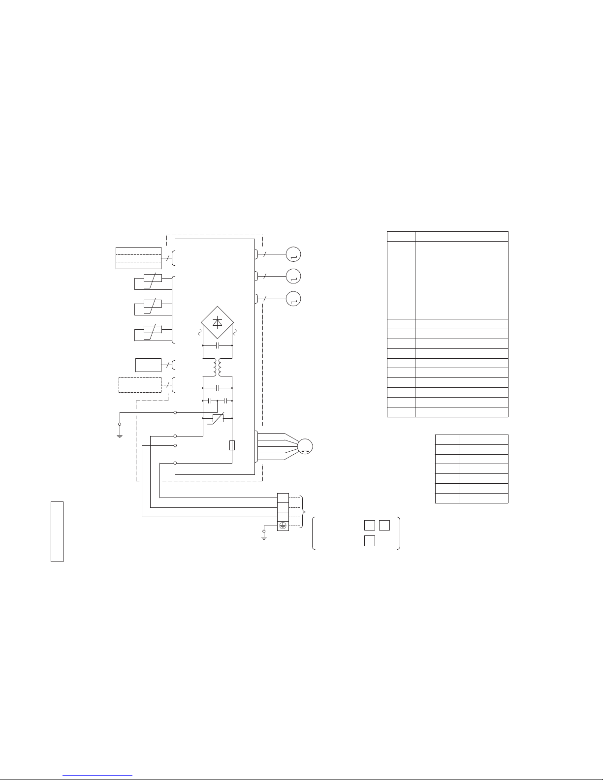
RC R 000Z 030
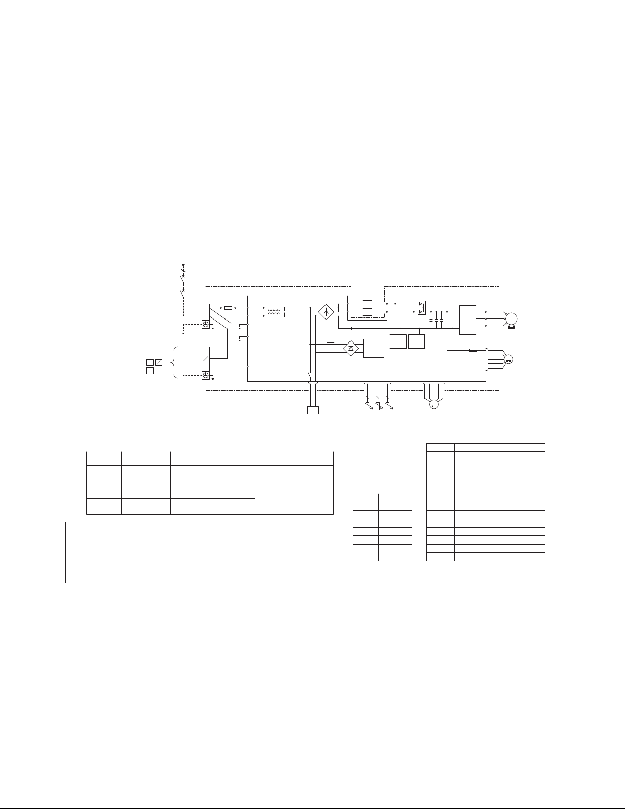
(2) Outdoor units
Models SRC63ZR-S, 71ZR-S, 80ZR-S
○
The specifications shown in the above table are for units without heaters. For units with heaters, refer
to the installation instructions or the construction instructions of the indoor unit.
○
Switchgear of Circuit breaker capacity which is calculated from MAX. over current should be chosen
along the regulations in each country.
○
The cable specifications are based on the assumption that a metal or plastic conduit is used with no
more than three cables contained in a conduit and a voltage drop is 2%. For an installation falling
outside of these conditions, please follow the internal cabling regulations. Adapt it to the regulation
in effect in each country.
Power cable, indoor-outdoor connecting wires
2
3
1
2
[ ]
N
DS1
DS2
SRC63ZR-S 14
2.5SRC71ZR-S
SRC80ZR-S
14.5
17.0
17.0
15
15
1.5mm
2
x 4
2.0
2.5
2.5
M
(BK)
(WH)
(RD)
V
W
U
PCB ASSY PCB1
M
MS
TRANSISTOR
POWER
POWER
T 1A L 250V
CM
FMo
W
V
UP
N
CNTH CNEEV
CNFAN
3〜
+
S.IN
R.IN
G1
N
L
250V 20A
F4
2
N
(Y/G)
C-2
(RD)
CN20S
(BK)
(WH)
(WH)
(WH)
F 3.15A L 250V
F1
(BK)
1
3
(BK)
(WH)
(Y/G)
(Y/G)
(RD)
G2
20S
(Y/G)
(BK)
〜〜+
−
SWITCHING
CIRCUIT
250V 20A
F8
++
CIRCUIT
PAM
CIRCUIT
PAM
(Y)
(BL)T1T11
T2
T12
(Y)
(BL)
+
F3
〜〜−
L1
L2
EEV
TH1 TH2 TH3
TERMINAL
BLOCK 2
TERMINAL
BLOCK 1
2 2 2
TO INDOOR UNIT
POWER WIRES
SIGNAL WIRE
TH3 Discharge pipe temp. sensor
TH2 Outdoor air temp. sensor
TH1 Heat exchanger sensor
L1,2 Reactor
FMo Fan motor
EEV Electric expansion valve(coil)
DS1,2 Diode stack
CM Compressor motor
CNTH
CNFAN
CNEEV
CN20S Connector
20S Solenoid coil for 4 way valve
Item Description
BK Black
Mark
Color Marks
Color
BL Blue
RD Red
WH White
Y Yellow
Y/G Yellow
/Green
MAX running current
(A)
Power cable size
(mm
2
)
Power cable length
(m)
Indoor-outdoor
wire size x number
Earth wire size
(mm
2
)
Model name
POWER SOURCE
1 Phase 220-240V 50Hz
220V 60Hz
-
14
-
'15 • SRK-T-175
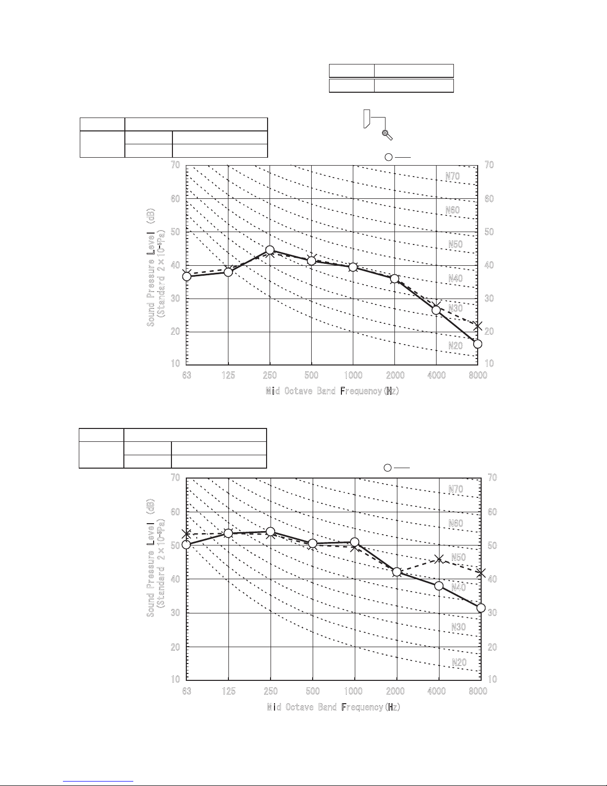
(Indoor Unit)
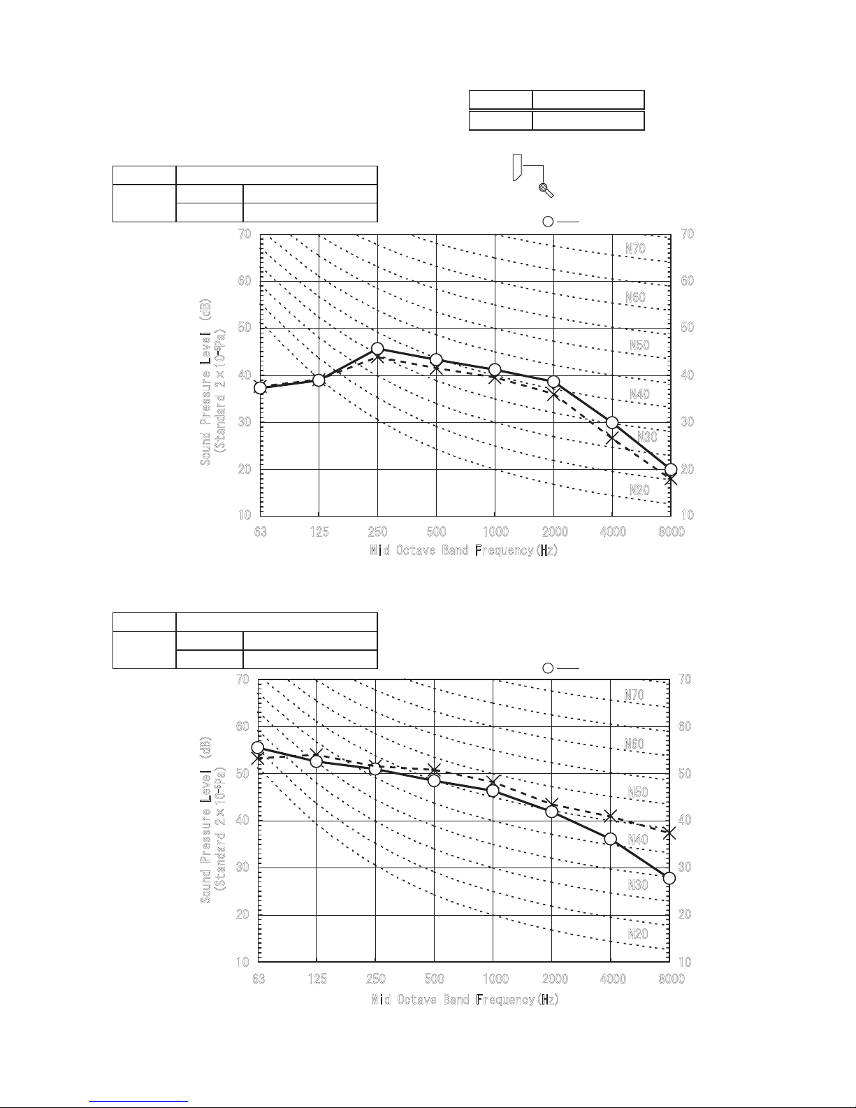
Model SRK63ZR-S
Noise
Level
Cooling 44 dB(A)
Heating 44 dB(A)
×
......
Cooling Heating
MODE
Rated capacity value
4. NOISE LEVEL
Model SRK63ZR-S
●
Mike position
0.8m
1m
Unit
Mike position
(Center & Low points)
(Outdoor Unit)
Model SRC63ZR-S
Noise
Level
Cooling 54 dB(A)
Heating 54 dB(A)
×
......
Cooling Heating
●
Mike position: at highest noise level in position as mentioned below
Distance from front side 1m
●
Mike position
0.8m
1m
Unit
Mike position
(Center & Low points)
So
un
d P
r
essur
e L
e
ve
l (dB
)
(St
an
dar
d 2×10
-5
Pa
)
1000 2000 4000 8000
1000 2000 4000 8000
10
20
30
40
50
60
70
63 125 250 500
Mid Octave Band Frequency(Hz)
10
20
30
40
50
60
70
63 125 250 500
Mid Octave Band Frequency(Hz)
S
ound Pr
essu
re Leve
l (d
B)
(Standard )
2×10
-5
Pa
N50
N30
N40
N60
N70
N20
10
20
30
40
50
60
70
10
20
30
40
50
60
70
N50
N30
N40
N60
N70
N20
Condition ISO5151 T1
-
15
-
'15 • SRK-T-175
(Outdoor Unit)
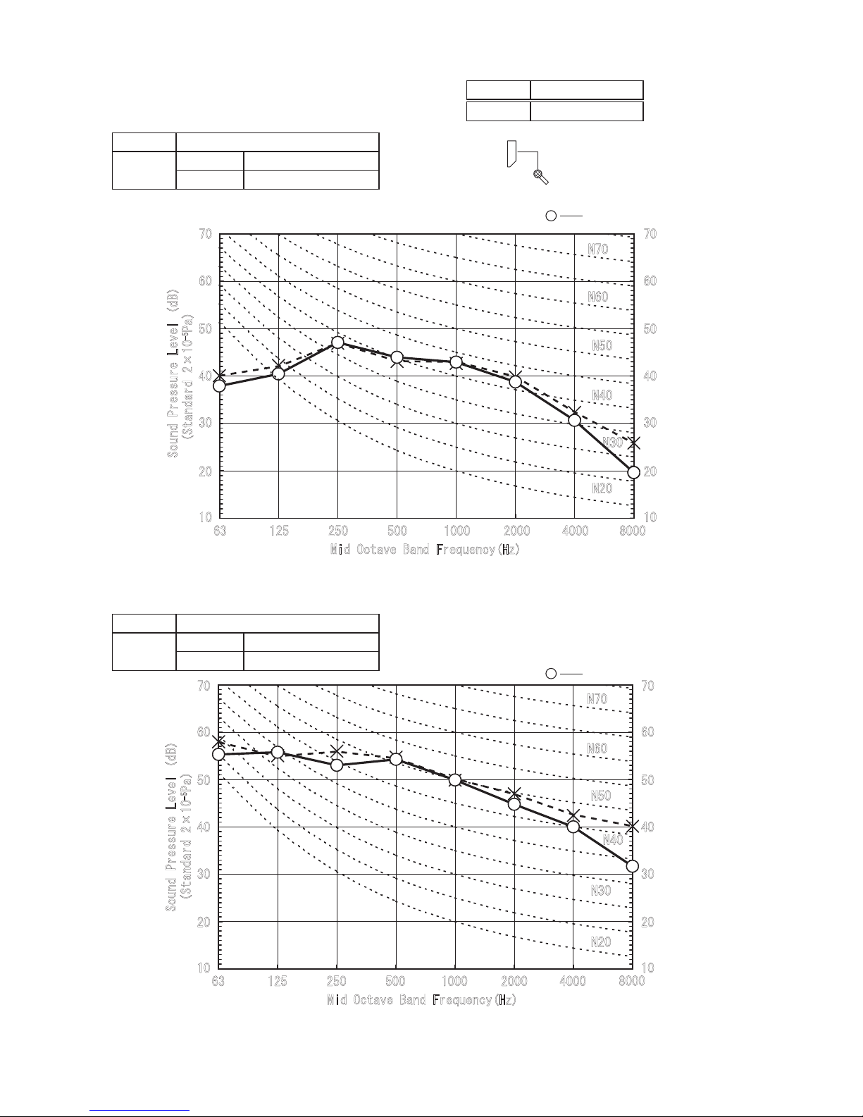
Model SRC71ZR-S
Noise
Level
Cooling 53 dB(A)
Heating 51 dB(A)
(Indoor Unit)
Model SRK71ZR-S
Noise
Level
Cooling 44 dB(A)
Heating 46 dB(A)
×
......
Cooling Heating
Model SRK71ZR-S
/KF1EVCXG$CPF(TGSWGPE[*\
5Q
WP
F
2T
GUUWT
G
.G
XG
NF$
5V
CP
FCT
F
2C
5QWPF
2TGU
UWTG
.GXGNF$
5V
CP
FCT
F
2C
/KF1EVCXG$CPF(TGSWGPE[*\
0
0
0
0
0
0
0
0
0
0
0
0
×
......
Cooling Heating
●
Mike position
0.8m
1m
Unit
Mike position
(Center & Low points)
●
Mike position: at highest noise level in position as mentioned below
Distance from front side 1m
●
Mike position
0.8m
1m
Unit
Mike position
(Center & Low points)
MODE
Rated capacity value
Condition ISO5151 T1
-
16
-
'15 • SRK-T-175
(Outdoor Unit)
Model SRC80ZR-S
Noise
Level
Cooling 56 dB(A)
Heating 55 dB(A)
(Indoor Unit)
Model SRK80ZR-S
Noise
Level
Cooling 47 dB(A)
Heating 47 dB(A)
×
......
Cooling Heating
×
......
Cooling Heating
●
Mike position
0.8m
1m
Unit
Mike position
(Center & Low points)
●
Mike position: at highest noise level in position as mentioned below
Distance from front side 1m
●
Mike position
0.8m
1m
Unit
Mike position
(Center & Low points)
5Q
WP
F
2T
GUUWT
G
.G
XG
NF$
5QWPF
2TGU
UWTG
.GXGN
F$
5V
CP
FCT
F
5V
CP
FCT
F
2C
2C
/KF1EVCXG$CPF(TGSWGPE[*\
/KF1EVCXG$CPF(TGSWGPE[*\
0
0
0
0
0
0
0
0
0
0
0
0
Model SRK80ZR-S
MODE
Rated capacity value
Condition ISO5151 T1
-
17
-
'15 • SRK-T-175
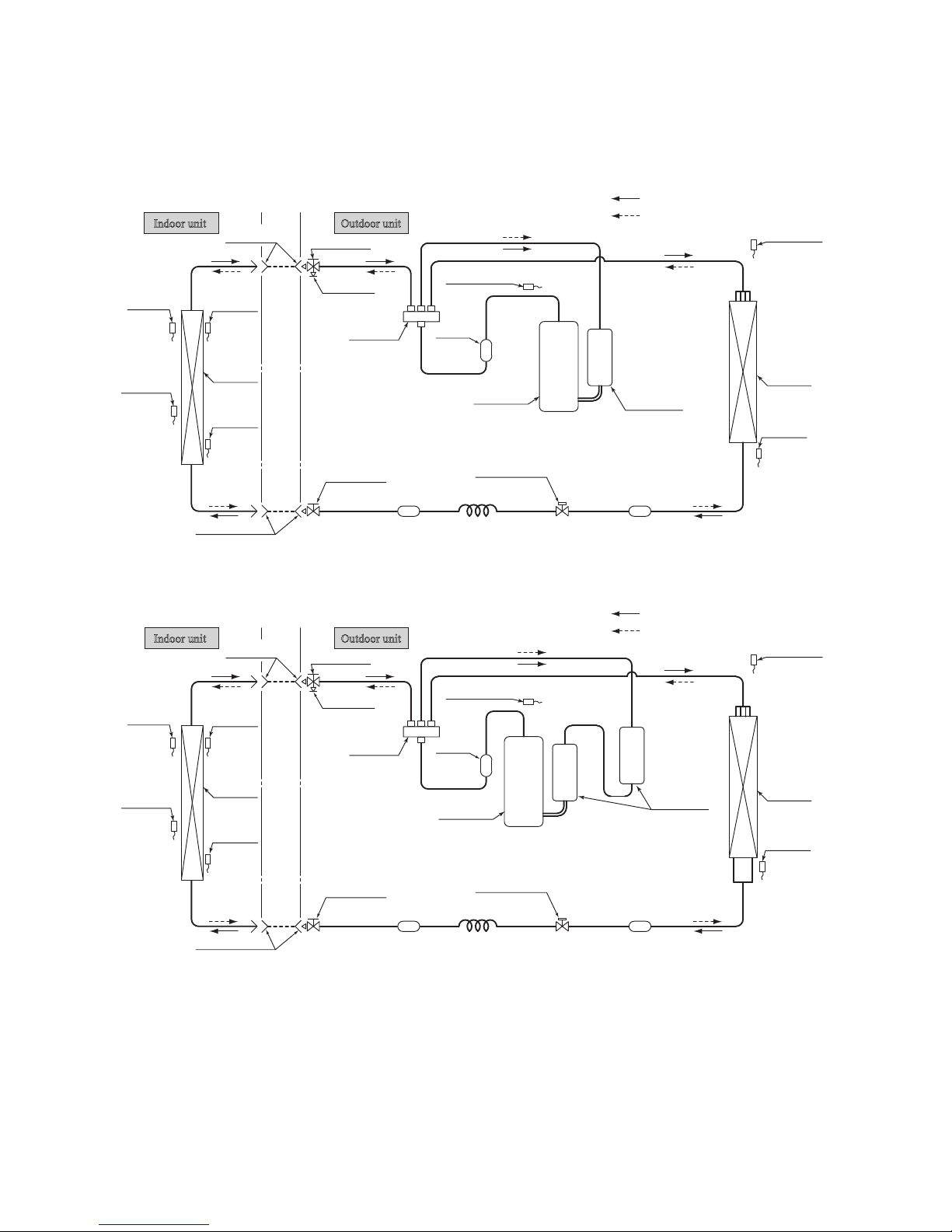
Indoor unit
Outdoor unit
Flare
connection
Flareconnection
Liquid
pipe
(
䃥
6.35)
Gas pipe
(䃥12.7)
Service valve
Heat
exchanger
Electronic
expansion valve
(Liquid)
Strainer Strainer
Capillary tube
Outdoor air
temp. sensor
Muffler
Compressor
Discharge pipe
temp. sensor
Cooling cycle
Heating cycle
Check joint
4way valve
Service valve
Heat
exchanger
sensor
(Th2
2)
(TH3)
Humidity
sensor
(Th3)
(
Gas
)
(TH2)
Heat
exchanger
sensor
(TH1)
(EEV)
Heat
exchanger
Room temp.
sensor
(Th1)
Heat
exchanger
sensor
(Th2
1)
Accumulator
5. PIPING SYSTEM
Model SRK63ZR-S
Indoor unit Outdoor unit
Flare
connection
Flareconnection
Liquid
pipe
(
䃥
6.35)
Gas pipe
(䃥15.88)
Service valve
Heat
exchanger
Electronic
expansion valve
(Liquid)
Strainer Muffler
Capillary tube
Outdoor air
temp. sensor
Muffler
Compressor
Discharge pipe
temp. sensor
Cooling cycle
Heating cycle
Check joint
4way valve
Service valve
Heat
exchanger
sensor
(Th2
2)
(TH3)
Humidity
sensor
(Th3)
(
Gas
)
(TH2)
Heat
exchanger
sensor
(TH1)
(EEV)
Heat
exchanger
Room temp.
sensor
(Th1)
Heat
exchanger
sensor
(Th2
1)
Accumulator
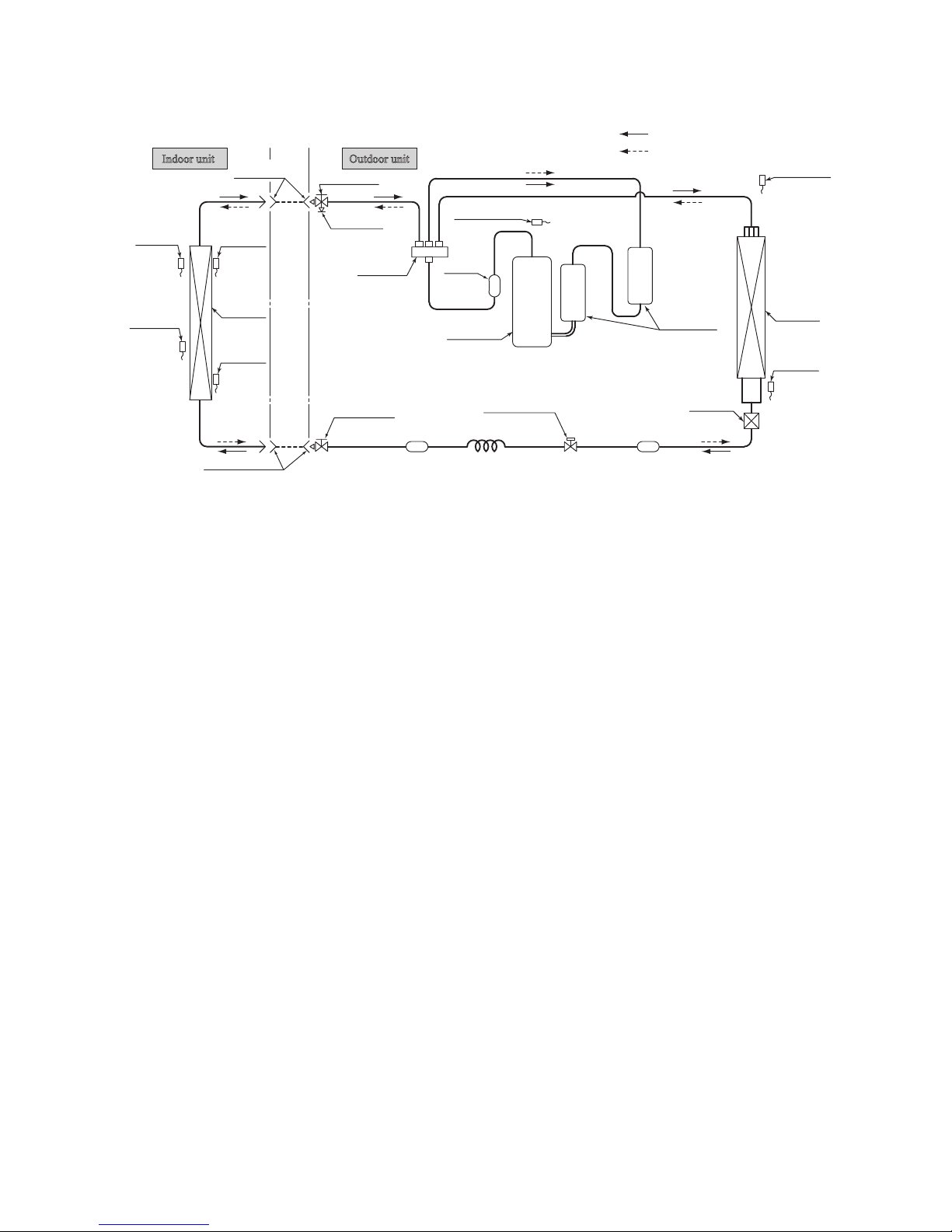
Model SRK71ZR-S
-
18
-
'15 • SRK-T-175
Indoor unit
Outdoor unit
Flare
connection
Flareconnection
Liquid
pipe
(
䃥
6.35)
Gas pipe
(䃥15.88)
Service valve
Heat
exchanger
Electronic
expansion valve
(Liquid)
Strainer Muffler
Capillary tube
Outdoor air
temp. sensor
Muffler
Compressor
Discharge pipe
temp. sensor
Cooling cycle
Heating cycle
Check joint
4way valve
Service valve
Heat
exchanger
sensor
(Th2
2)
(TH3)
Humidity
sensor
(Th3)
(
Gas
)
(TH2)
Heat
exchanger
sensor
(TH1)
(EEV)
Heat
exchanger
Heat
exchanger
Room temp.
sensor
(Th1)
Heat
exchanger
sensor
(Th2
1)
Accumulator
Model SRK80ZR-S
-
19
-
'15 • SRK-T-175
6. RANGE OF USAGE & LIMITATIONS
6. RANGE OF USAGE & LIMITATIONS
Indoor return air temperature
(Upper, lower limits)
Refrigerant line (one way) length
Power source voltage Rating ±10%
Voltage at starting Min. 85% of rating
Frequency of ON-OFF cycle
Max. 7 times/h
(Inching prevention 5-9 minutes)
ON and OFF interval Min. 3 minutes
Outdoor air temperature
(Upper, lower limits)
Vertical height difference between
outdoor unit and indoor unit
Max. 30m
Max. 20m (Outdoor unit is higher)
Max. 20m (Outdoor unit is lower)
Item
Model
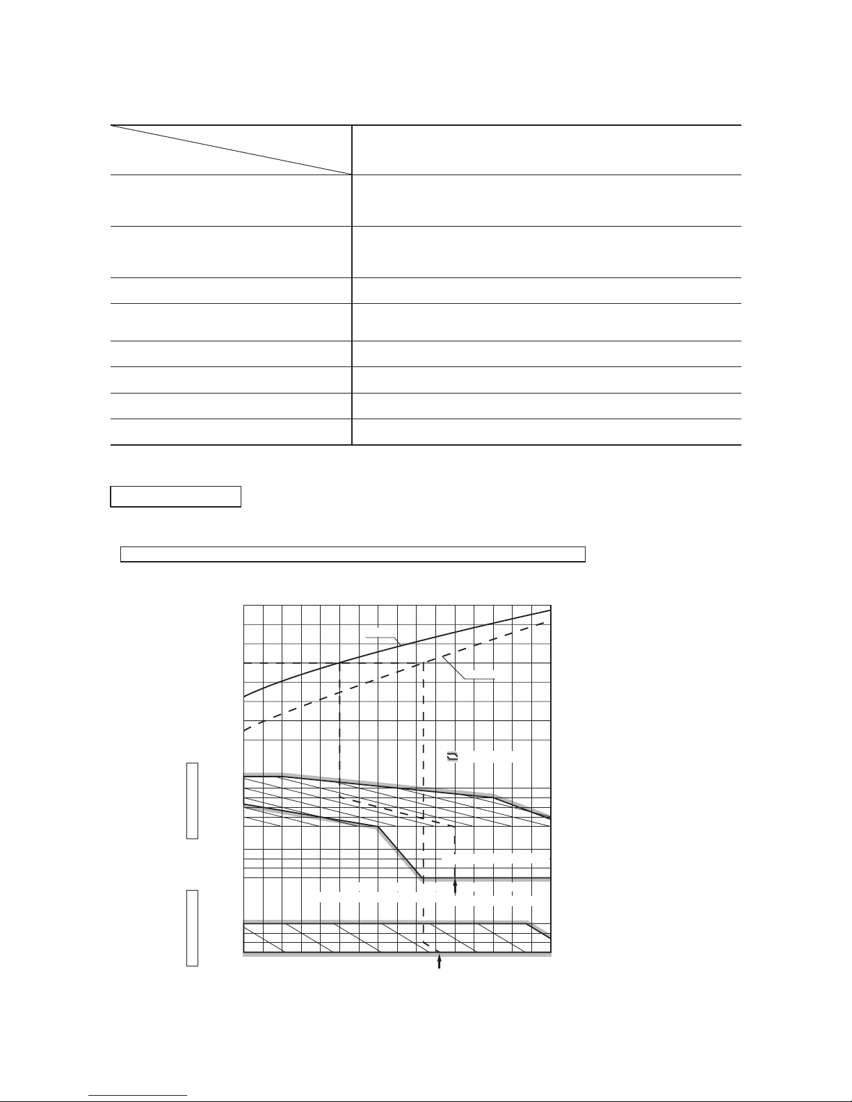
SRK63ZR-S,71ZR-S,80ZR-S
Cooling operation : Approximately 18 to 32℃ D.B.
Heating operation : Approximately 15 to 30℃ D.B.
(Refer to the selection chart)
Cooling operation : Approximately -15 to 46℃ D.B.
Heating operation : Approximately -15 to 24℃ D.B.
(Refer to the selection chart)
Selection chart
Correct the cooling and heating capacity in accordance with the conditions as follows. The net cooling and heating capacity can be
obtained in the following way.
Net capacity = Capacity shown on specification ×Correction factors as follows.
(1) Coefficient of cooling and heating capacity in relation to temperatures
SRK25ZJP-S1,35ZJP-S1 SRK50ZJP-S1
Net capacity = Capacity shown on specification Correction factors as follows.
(1) Coefficient of cooling and heating capacity in relation to temperatures
7
0.6
0.7
0.8
0.9
1.0
1.2
1.1
1.3
0
-5
-10
-15
24
26
20
25
30
35
40
46
15
20
25
30
Outdoor air W.B. temperature °C W.B.
-10 -5 0 5 10 15
.
Cooling operation
Outdoor air D.B.
temperature
°C D. B.
Coefficient of cooling
&
Heating capacity in
relation to temperature
Heating operation
Indoor air D.B.
temperature
°C D. B.
ISO-T1 Standard Condition
Depends on installed situation
ISO-T1 Standard Condition
2220181614
Indoor air W.B. temperature °C W.B
Applicable range
Cooling
Heating
-
20
-
'15 • SRK-T-175
'09•SRK-DB-087D
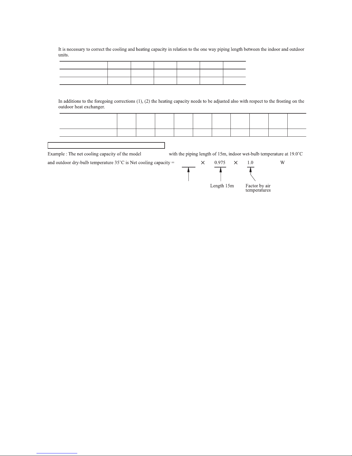
(2) Correction of cooling and heating capacity in relation to one way length of refrigerant piping
(3) Correction relative to frosting on outdoor heat exchanger during heating
How to obtain the cooling and heating capacity
ѳ
Piping length [m]
Cooling
Heating
7
1.0
1.0
10
0.99
1.0
15
0.975
1.0
20
0.965
1.0
25
0.95
1.0
30
0.935
1.0
Air inlet temperature of
outdoor unit in °C WB
Adjustment coefficient
-15
0.95 0.95 0.94 0.93 0.91 0.88 0.86 0.87 0.92 1.00
-10 -9 -7 -5 -3 -1 1 3
5 or more
SRK63ZR-S
6.3
SRK63ZR-S
6.2k
-
21
-
'15 • SRK-T-175
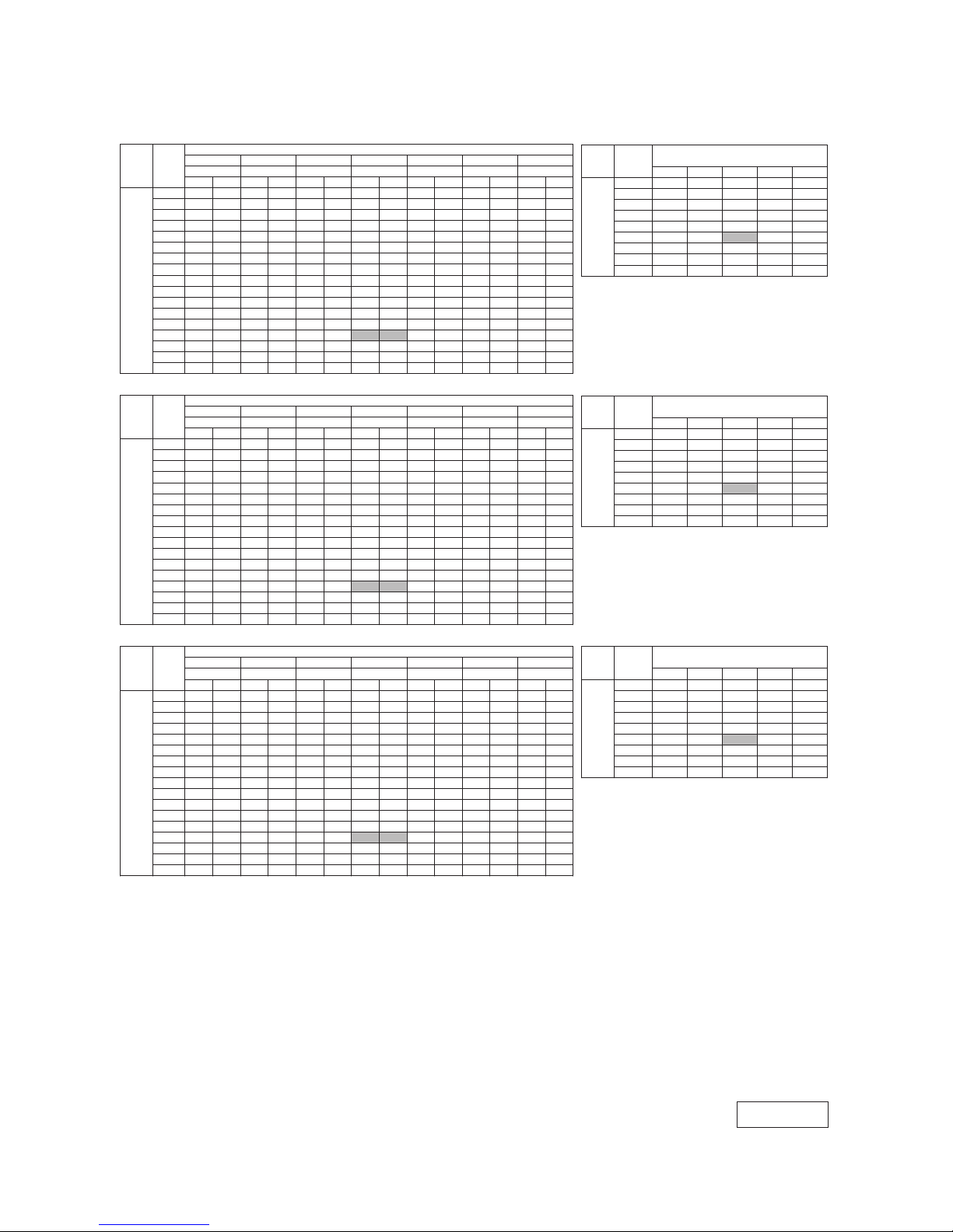
7. CAPACITY TABLES
ISC15023
9.21 9.10 9.00 8.89 8.78
8.19 8.09 8.00 7.90 7.80
7.27 7.18 7.10 7.01 6.93
ting ModeaeHling Mode (kW) (kW)ooC
Outdoor
℃DB 23 ℃DB 26 ℃DB 27 ℃DB 28 ℃DB 31 ℃DB 33 ℃DB
Outdoor
air temp.
℃WB
air temp.
℃WB 16 ℃WB 18 ℃WB 19 ℃WB 20 ℃WB 22 ℃WB 24 ℃WB
Air flow
61
CHSCTCHSCTCHSCTCHSCTCHSCTCHSCTCHSCT
℃ DB 18℃ DB 20℃ DB 22℃ DB 24℃ DB
10 7.10 5.84 7.43 5.74 7.70 5.98 7.83 5.91 7.97 5.84 8.20 6.05 8.42 5.87
4.37 4.27 4.17 4.09 4.00
12 6.97 5.77 7.30 5.69 7.59 5.94 7.73 5.87 7.87 5.80 8.11 6.02 8.34 5.85
4.94 4.86 4.79 4.67 4.57
14 6.84 5.71 7.18 5.62 7.48 5.88 7.62 5.82 7.77 5.75 8.02 5.98 8.26 5.82
5.35 5.28 5.17 5.11 5.03
16 6.70 5.64 7.04 5.56 7.37 5.84 7.52 5.78 7.66 5.71 7.93 5.94 8.17 5.79
5.61 5.53 5.43 5.37 5.29
18 6.56 5.58 6.91 5.50 7.25 5.79 7.40 5.73 7.55 5.67 7.83 5.91 8.08 5.77
7.15 7.07 7.03 6.89 6.79
20 6.42 5.50 6.77 5.44 7.12 5.74 7.29 5.69 7.43 5.63 7.73 5.88 7.98 5.74
(
m
3
/
min
)
6
0
Hi 22 6.28 5.43 6.62 5.37 6.99 5.69 7.17 5.64 7.31 5.58 7.62 5.84 7.88 5.67
7.72 7.65 7.60 7.50 7.42
20.5 24 6.12 5.36 6.47 5.30 6.86 5.62 7.04 5.60 7.19 5.54 7.51 5.80 7.77 5.63
8.40 8.33 8.27 8.18 8.10
(
m3/min
)
26 5.97 5.29 6.32 5.24 6.73 5.57 6.92 5.54 7.06 5.48 7.40 5.73 7.67 5.60
9.03 8.96 8.92 8.81 8.74
28 5.81 5.21 6.16 5.17 6.59 5.52 6.79 5.49 6.93 5.44 7.28 5.69 7.55 5.57
30 5.65 5.14 6.00 5.09 6.44 5.46 6.65 5.44 6.80 5.39 7.16 5.65 7.44 5.53
32 5.49 5.06 5.83 5.02 6.30 5.40 6.51 5.38 6.66 5.34 7.03 5.61 7.32 5.50
34 5.32 4.99 5.66 4.95 6.15 5.33 6.37 5.33 6.52 5.29 6.90 5.57 7.19 5.46
36 5.14 4.90 5.49 4.88 5.99 5.27 6.23 5.27 6.38 5.22 6.77 5.52 7.06 5.42
38 4.97 4.82 5.31 4.80 5.83 5.21 6.08 5.21 6.23 5.17 6.64 5.48 6.93 5.38
39 4.88 4.78 5.22 4.76 5.75 5.18 6.00 5.18 6.15 5.14 6.57 5.46 6.87 5.36
Air flow
℃DB 23 ℃DB 26 ℃DB 27 ℃DB 28 ℃DB 31 ℃DB 33 ℃DB
air temp.
℃WB 16 ℃WB 18 ℃WB 19 ℃WB 20 ℃WB 22 ℃WB 24 ℃WB
61
CHSCTCHSCTCHSCTCHSCTCHSCTCHSCTCHSCT
℃ DB 18℃ DB 20℃ DB 22℃ DB 24℃ DB
10 8.00 6.34 8.37 6.23 8.68 6.46 8.83 6.38 8.98 6.30 9.24 6.48 9.49 6.29
4.92 4.82 4.70 4.61 4.50
12 7.86 6.26 8.23 6.17 8.56 6.41 8.71 6.33 8.87
6.25 9.15 6.45 9.40 6.26
5.57 5.47 5.40 5.26 5.15
14 7.71 6.19 8.09 6.09 8.43 6.36 8.59 6.28 8.75 6.21 9.04 6.41 9.31 6.23
6.03 5.94 5.82 5.76 5.67
16 7.55 6.11 7.94 6.02 8.30 6.29 8.47 6.23 8.63 6.15 8.93 6.37 9.21 6.20
6.32 6.23 6.12 6.05 5.96
18 7.40 6.04 7.78 5.95 8.17 6.24 8.34 6.17 8.51 6.10 8.82 6.33 9.10 6.17
8.06 7.96 7.92 7.76 7.65
20 7.24 5.96 7.62 5.88 8.03 6.18 8.21 6.12 8.38 6.05 8.71 6.29 8.99 6.13
(
m
3
/
min
)
Hi 22 7.07 5.87 7.46 5.81 7.88 6.12 8.08 6.07 8.24 6.00 8.59 6.25 8.88 6.09
8.70 8.62 8.56 8.45 8.36
20.5 24 6.90 5.79 7.29 5.72 7.73 6.06 7.94 6.01 8.10 5.95 8.46 6.21 8.76 6.06
9.47 9.38 9.32 9.21 9.13
(
m3/min
)
26 6.73 5.71 7.12 5.65 7.58 5.99 7.79 5.96 7.96 5.89 8.33 6.16 8.64 6.02
10.17 10.09 10.05 9.93 9.85
28 6.55 5.62 6.94 5.57 7.42 5.92 7.65 5.89 7.81 5.83 8.20 6.12 8.51 5.98
30 6.37 5.54 6.76 5.49 7.26 5.85 7.50 5.83 7.66 5.77 8.07 6.06 8.38 5.92
32 6.18 5.44 6.57 5.40 7.10 5.79 7.34 5.77 7.51 5.71 7.92 6.01 8.25 5.88
34 5.99 5.35 6.38 5.31 6.93 5.72 7.18 5.70 7.35 5.65 7.78 5.96 8.11 5.84
36 5.80 5.26 6.18 5.23 6.75 5.65 7.02 5.64 7.19 5.59 7.63 5.91 7.96 5.79
38 5.60 5.17 5.98 5.14 6.58 5.57 6.85 5.58 7.02 5.53 7.48 5.86 7.81 5.75
39 5.50 5.13 5.88 5.10 6.48 5.53 6.76 5.54 6.93 5.50 7.40 5.83 7.74 5.72
Air flow
℃DB 23 ℃DB 26 ℃DB 27 ℃DB 28 ℃DB 31 ℃DB 33 ℃DB
air temp.
℃WB 16 ℃WB 18 ℃WB 19 ℃WB 20 ℃WB 22 ℃WB 24 ℃WB
61
CHSCTCHSCTCHSCTCHSCTCHSCTCHSCTCHSCT
℃ DB 18℃ DB 20℃ DB 22℃ DB 24℃ DB
10 9.01 7.27 9.43 7.15 9.78 7.44 9.95 7.34 10.12 7.25 10.42 7.49 10.70 7.28
5.54 5.42 5.29 5.18 5.06
12 8.85 7.18 9.28 7.08 9.64 7.38 9.82 7.29 9.99
7.20 10.30 7.45 10.59 7.25
6.27 6.15 6.07 5.92 5.79
14 8.68 7.10 9.11 7.00 9.50 7.31 9.68 7.23 9.86 7.14 10.19 7.40 10.49 7.20
6.79 6.69 6.55 6.48 6.37
16 8.51 7.02 8.94 6.92 9.35 7.25 9.54 7.17 9.72 7.09 10.07 7.36 10.37 7.16
7.12 7.01 6.89 6.81 6.71
18 8.34 6.93 8.77 6.85 9.20 7.19 9.40 7.12 9.58 7.04 9.94 7.31 10.25 7.12
9.06 8.96 8.91 8.73 8.61
20 8.15 6.84 8.59 6.76 9.04 7.12 9.25 7.06 9.44 6.98 9.81 7.27 10.13 7.08
(
m
3
/
min
)
Hi 22 7.97 6.75 8.41 6.67 8.88 7.05 9.10 7.00 9.29 6.92 9.68 7.22 10.00 7.04
9.79 9.69 9.63 9.50 9.41
23.5 24 7.78 6.66 8.22 6.58 8.71 6.98 8.94 6.93 9.13 6.86 9.54 7.17 9.87 7.00
10.65 10.56 10.48 10.37 10.27
(
m3/min
)
26 7.58 6.57 8.02 6.50 8.54 6.91 8.78 6.87 8.97 6.80 9.39 7.12 9.73 6.90
11.45 11.35 11.30 11.17 11.08
28 7.38 6.47 7.82 6.41 8.36 6.84 8.62 6.80 8.81 6.73 9.24 7.06 9.59 6.90
30 7.18 6.37 7.62 6.32 8.18 6.76 8.45 6.73 8.64 6.67 9.09 7.01 9.44 6.86
32 6.97 6.28 7.40 6.23 8.00 6.69 8.27 6.66 8.46 6.60 8.93 6.96 9.29 6.81
34 6.75 6.18 7.19 6.13 7.81 6.61 8.09 6.59 8.28 6.54 8.77 6.90 9.13 6.76
36 6.53 6.08 6.97 6.04 7.61 6.53 7.91 6.52 8.10 6.47 8.60 6.84 8.97 6.71
38 6.31 5.97 6.74 5.94 7.41 6.45 7.72 6.45 7.91 6.40 8.43 6.78 8.80 6.65
39 6.20 5.92 6.62 5.89 7.31 6.41 7.62 6.41 7.81 6.36 8.34 6.75 8.72 6.63
Indoor air temp.
Indoor air temp.
Indoor air temp.
Model SRK63ZR-S
23.5
10
15
20
-5
-10
-15
Hi
6
0
10
15
20
-5
-10
-15
25.5
Hi
6
0
10
15
20
-5
-10
-15
26.5
Hi
ting ModeaeH(kW)
ting ModeaeH(kW)
ling ModeooC
ling ModeooC
Model SRK71ZR-S
Model SRK80ZR-S
Note(1) These data show average statuses.
Note(1) Depending on the system control, there may be ranges where the operation
is not conducted continuously.
Note(1) These data show the case where the operation frequency of a compressor is
fixed.
(2) Capacities are based on the following conditions.
(2) Corresponding refrigerant piping length :7m
(2) Level difference of Zero.
(3) Symbols are as follows.
TC : Total cooling capacity (kW)
SHC : Sensible heat capacity (kW)
HC : Heating capacity (kW)
35 5.23 4.95 5.57 4.92 6.07 5.30 6.30 5.29 6.45 5.26 6.84 5.55 7.13 5.44
Indoor air temp.
(kW)
(kW)
Air flow
Indoor air temp.
Air flow
Indoor air temp.
35 6.64 6.13 7.08 6.08 7.71 6.57 8.00 6.56 8.19 6.50 8.68 6.87 9.05 6.73
35 5.90 5.31 6.28 5.27 6.84 5.68 7.10 5.67 7.27 5.62 7.71 5.93 8.03 5.81
℃DB
14
21
Air flow
℃DB
14
21
Outdoor
℃DB
21
14
Outdoor
Outdoor
air temp.
℃WB
Outdoor
air temp.
℃WB
5
5
5
-
22
-
'15 • SRK-T-175
R410A REFRIGERANT USED
WALL TYPEAIR-CONDITIONER
INSTALLATION MANUAL FOR INDOOR UNIT
RLD012A001
WARNING
• Installation must be carried out by the qualified installer.
If you install the system by yourself, it may cause serious trouble such as
water leaks, electric shocks, fire and personal injury, as a result of a
system malfunction. Do not carry out the installation and maintenance
work except the by qualified installer.
• Install the system in full accordance with the installation manual.
Incorrect installation may cause bursts, personal injury, water leaks,
electric shocks and fire.
• Be sure to use only for household and residence.
If this appliance is installed in inferior environment such as machine shop
and etc., it can cause malfunction.
• Use the original accessories and the specified components for
installation.
If parts other than those prescribed by us are used, It may cause water
leaks, electric shocks, fire and personal injury.
• Install the unit in a location with good support.
Unsuitable installation locations can cause the unit to fall resulting in
material damage and personal injury.
• Ventilate the working area well in the event of refrigerant leakage
during installation.
If the refrigerant comes into contact with naked flames, poisonous gas is
produced.
• When installing in small rooms, take prevention measures not to
exceed the density limit of refrigerant in the event of leakage,
referred by the formula (accordance with ISO5149).
If the density of refrigerant exceeds the limit, consult the dealer and
install the ventilation system, otherwise lack of oxygen can occur, which
can cause serious accident.
• After completing installation, check that no refrigerant leaks from
the system.
If refrigerant leaks into the room and comes into contact with an oven or
other hot surface, poisonous gas is produced.
• Use the prescribed pipes, flare nuts and tools for R410A.
Using existing parts (for R22 or R407C) can cause the unit failure and
serious accidents due to burst of the refrigerant circuit.
• Tighten the flare nut by torque wrench with specified method.
If the flare nuts were tightened with excess torque, this may cause burst
and refrigerant leakage after a long period.
• The electrical installation must be carried out by the qualified
electrician in accordance with “the norm for electrical work” and
“national wiring regulation”, and the system must be connected to
the dedicated circuit.
Power source with insufficient capacity and incorrect function done by
improper work can cause electric shocks and fire.
• Be sure to shut off the power before starting electrical work.
Failure to shut off the power can cause electric shocks, unit failure or
incorrect function of equipment.
• Be sure to use the cables conformed to safety standard and cable
ampacity for power distribution work.
Unconformable cables can cause electric leak, anomalous heat
production or fire.
• This appliance must be connected to main power source by means
of a circuit breaker or switch [fuse Model 63(21):16A, Model 71(24),
80(28), 92, 100:20A] with a contact separation of at least 3mm.
• When plugging this appliance, a plug conforming to the norm
IEC60884-1 must be used.
• Use the prescribed cables for electrical connection, tighten the
cables securely in terminal block and relieve the cables correctly to
prevent overloading the terminal blocks.
Loose connections or cable mountings can cause anomalous heat
production or fire.
• Arrange the wiring in the control box so that it cannot be pushed up
further into the box. Install the service panel correctly.
Incorrect installation may result in overheating and fire.
• Be sure to switch off the power source in the event of installation,
inspection or servicing.
If the power source is not shut off, there is a risk of electric shocks, unit
failure or personal injury due to the unexpected start of fan.
• Be sure to wear protective goggles and gloves while at work.
• Earth leakage breaker must be installed.
If the earth leakage breaker is not installed, it can cause electric shocks.
CAUTION
• Use the circuit breaker of correct capacity. Circuit breaker should be able to
disconnect all poles under over current.
Using the incorrect one could cause the system failure and fire.
• Install isolator or disconnect switch on the power
source
wiring in
accordance with the local codes and regulations.
The isolator should be locked in OFF state in accordance with EN60204-1.
• Be sure to install indoor unit properly according to instruction manual so
that drainage can run off smoothly.
Improper installation of indoor unit can cause dropping water into the room and
damaging personal property.
• Install the drainage pipe to run off drainage securely according to the
installation manual.
Incorrect installation of the drainage pipe can cause dropping water into the room
and damaging personal property.
• Be sure to install the drainage pipe with descending slope of 1/100 or more,
and not to make traps and air-bleedings.
Check if the drainage runs off securely during commissioning and ensure the
space for inspection and maintenance.
• After maintenance, all wiring, wiring ties and the like, should be returned to
their original state and wiring route, and the necessary clearance from all
metal parts should be secured.
• Secure a space for installation, inspection and maintenance specified in the
manual.
Insufficient space can result in accident such as personal injury due to falling
from the installation place.
• Take care when carrying the unit by hand.
If the unit weights more than 20kg, it must be carried by two or more persons. Do
not carry by the plastic straps, always use the carry handle when carrying the unit
by hand. Use gloves to minimize the risk of cuts by the aluminum fins.
• Dispose of any packing materials correctly.
Any remaining packing materials can cause personal injury as it contains nails
and wood. And to avoid danger of suffocation, be sure to keep the plastic
wrapper away from children and to dispose after tear it up.
• For installation work, be careful not to get injured with the heat exchanger,
piping flare portion or screws etc.
• Be sure to insulate the refrigerant pipes so as not to condense the ambient
air moisture on them.
Insufficient insulation can cause condensation, which can lead to moisture
damage on the ceiling, floor, furniture and any other valuables.
• When perform the air-conditioner operation (cooling or dehumidifying
operation) in which ventilator is installed in the room. In this case, using the
air-conditioner in parallel with the ventilator, there is the possibility that
drain water may backflow in accordance with the room lapse into the
negative pressure status. Therefore, set up the opening port such as
incorporate the air into the room that may appropriate to ventilation (For
example; Open the door a little). In addition, just as above, so set up the
opening port if the room lapse into negative pressure status due to register
of the wind for the high rise apartment etc.
• Be sure to perform air tightness test by pressurizing with nitrogen gas after
completed refrigerant piping work.
If the density of refrigerant exceeds the limit in the event of refrigerant leakage in
the small room, lack of oxygen can occur, which can cause serious accidents.
• Do not install the unit in the locations listed below.
• Locations where carbon fiber, metal powder or any powder is floating.
• Locations where any substances that can affect the unit such as sulphide
gas, chloride gas, acid and alkaline can occur.
• Vehicles and ships.
• Locations where cosmetic or special sprays are often used.
• Locations with direct exposure of oil mist and steam such as kitchen and
machine plant.
• Locations where any machines which generate high frequency harmonics
are used.
• Locations with salty atmospheres such as coastlines.
• Locations with heavy snow (If installed, be sure to provide base flame and
snow hood mentioned in the manual).
• Locations where the unit is exposed to chimney smoke.
• Locations at high altitude (more than 1000m high).
• Locations with ammonic atmospheres (e.g. organic fertilizer).
• Locations with calcium chloride (e.g. snow melting agent).
• Locations where heat radiation from other heat source can affect the unit.
• Locations without good air circulation.
• Locations withany obstacleswhich can preventinlet andoutlet air of theunit.
• Locations where short circuit of air can occur (in case of multiple units
installation).
• Locations where strong air blows against the air outlet of outdoor unit.
• Locations where something located above the unit could fall.
It can cause remarkable decrease in performance, corrosion and damage of
components, malfunction and fire.
• Do not install the indoor unit in the locations listed below (Be sure to
install the indoor unit according to the installation manual for each
model because each indoor unit has each limitation).
•
Locations with any obstacles which can prevent inlet and outlet air of the unit.
•
Locations where vibration can be amplified due to insufficient strength of structure.
• Locations where the infrared receiver is exposed to the direct sunlight or
the strong light beam (in case of the infrared specification unit).
• Locations where an equipment affected by high harmonics is placed (TV
set or radio receiver is placed within 1m).
• Locations where drainage cannot run off safely.
It can affect performance or function and etc.
• Do not install the unit near the location where leakage of
combustible
gases can occur.
If leaked gases accumulate around the unit, it can cause fire.
• Do not install the unit where corrosive gas (such as sulfurous acid
gas etc.) or combustible gas (such as thinner and petroleum gases)
can accumulate or collect, or where volatile combustible substances
are handled.
Corrosive gas can cause corrosion of heat exchanger, breakage of plastic
parts and etc. And combustible gas can cause fire.
• Do not use the indoor unit at the place where water splashes may
occur such as in laundries.
Since the indoor unit is not waterproof, it can cause electric shocks and fire.
• Do not install nor use the system close to the equipment that
generates electromagnetic fields or high frequency harmonics.
Equipment such as inverters, standby generators, medical high frequency
equipments and telecommunication equipments can affect the system, and
cause malfunctions and breakdowns. The system can also affect medical
equipment and telecommunication equipment, and obstruct its function or
cause jamming.
• Do not place any variables which will be damaged by getting wet
under the indoor unit.
When the relative humidity is higher than 80% or drainage pipe is clogged,
condensation or drainage water can drop and it can cause the damage of
valuables.
• Do not install the remote control at the direct sunlight.
It can cause malfunction or deformation of the remote control.
•
Do not use the unit for special purposes such as storing foods,
cooling precision instruments and preservation of animals, plants
or art.
It can cause the damage of the items.
• Do not use any materials other than a fuse with the correct rating in
the location where fuses are to be used.
Connecting the circuit with copper wire or other metal thread can cause unit
failure and fire.
• Do not touch any buttons with wet hands.
It can cause electric shocks.
• Do not touch any refrigerant pipes with your hands when the system
is in operation.
During operation the refrigerant pipes become extremely hot or extremely cold
depending the operating condition, and it can cause burn injury or frost injury.
• Do not wash the inside of the air-conditioner.
Water leakage and permanent damage may result.
Electrical hazard exists.
• Carry out the electrical work for ground lead with care.
Do not connect the ground lead to the gas line, water line, lightning conductor or telephone line’s ground lead. Incorrect grounding can cause unit
faults such as electric shocks due to short-circuiting.
• Do not put the drainage pipe directly into drainage channels where
poisonous gases such as sulphide gas can occur.
Poisonous gases will flow into the room through drainage pipe and
seriously affect the user’s health and safety.This can also cause the
corrosion of the indoor unit and a resultant unit failure or refrigerant leak.
• Ensure that no air enters in the refrigerant circuit when the unit is
installed and removed.
If air enters in the refrigerant circuit, the pressure in the refrigerant circuit
becomes too high, which can cause burst and personal injury.
• Do not process or splice the power cord, or share the socket with
other power plugs.
This may cause fire or electric shock due to defecting contact, defecting
insulation and over-current etc.
• Do not bundle or wind or process the power cord. Do not deform
the power cord by treading it.
This may cause fire or heating.
• Do not vent R410A into the atmosphere : R410A is a fluorinated
greenhouse gas, covered by the Kyoto Protocol with Groval
Warming Potential (GWP)=1975.
• Do not run the unit with removed panels or protections.
Touching rotating equipments, hot surfaces or high voltage parts can
cause personal injury due to entrapment, burn or electric shocks.
•
Do not perform any change of protective device itself or its setup
condition.
The forced operation by short-circuiting protective device of pressure
switch and temperature controller or the use of non specified component
can cause fire or burst.
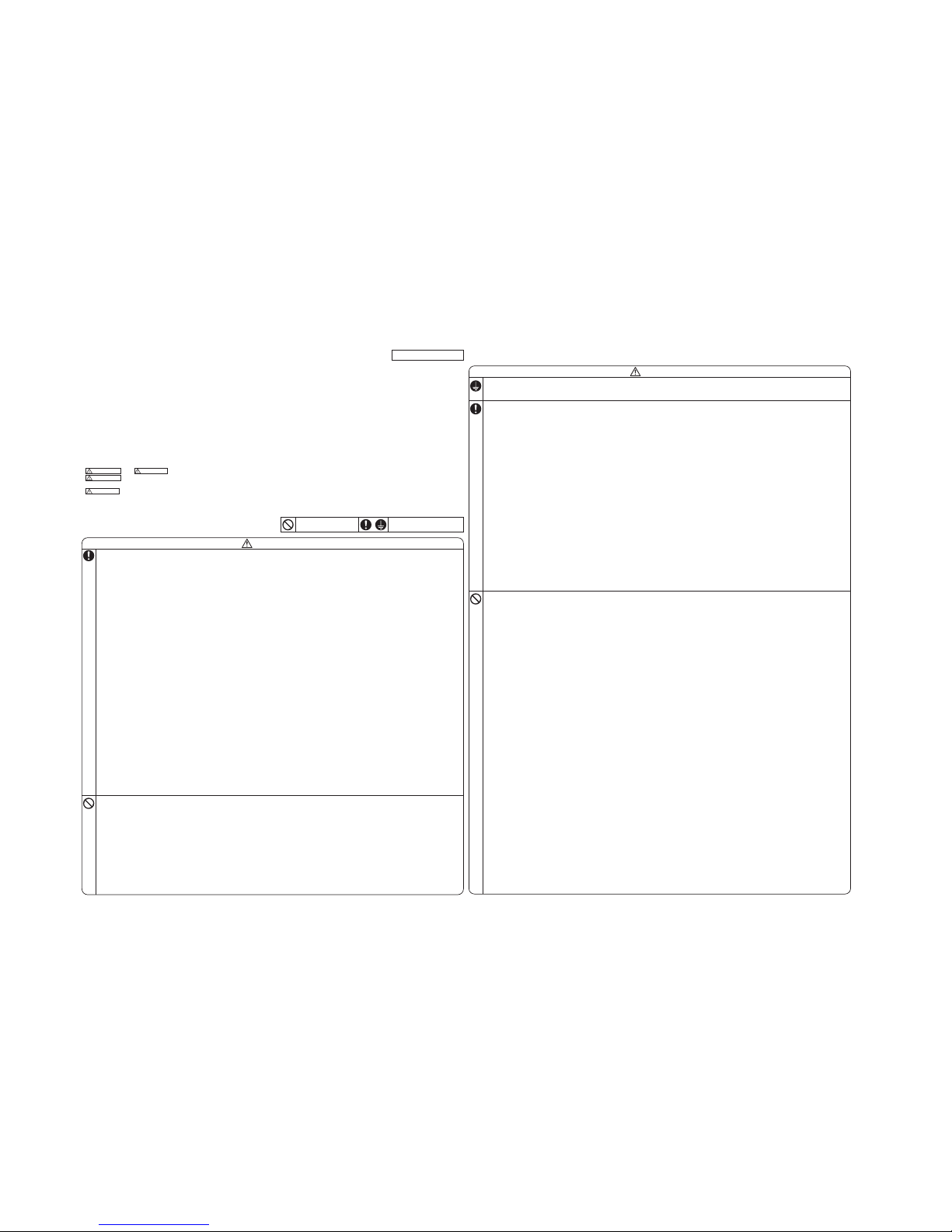
SAFETY PRECAUTIONS
• Before installation, read the “SAFETY PRECAUTIONS” carefully and strictly
follow it during the installation work in order to protect yourself.
• The precautionary items mentioned below are distinguished into two levels,
and .
: Wrong installation would cause serious consequences such
as injuries or death.
: Wrong installation might cause serious consequences
depending on circumstances.
Both mention the important items to protect your health and safety so strictly
follow them by any means.
•
Be sure to confirm no anomaly on the equipment by commissioning after completed
installation and explain the operating methods as well as the maintenance methods
of this equipment to the user according to the owner’s manual.
• Keep the installation manual together with owner’s manual at a place where
any user can read at any time. Moreover if necessary, ask to hand them to a
new user.
• Before starting the installation work, proper precautions (using suitable
protective clothing, groves etc.) should be taken by qualified installer.
• Pay attention not to fall down the tools, etc. when installing the unit at the
high position.
• If unusual noise can be heard during operation, consult the dealer.
• The meanings of “Marks” used here are shown as follows:
Never do it under any
circumstances.
Always do it according to the
instruction.
CAUTION
WARNING
CAUTION
WARNING
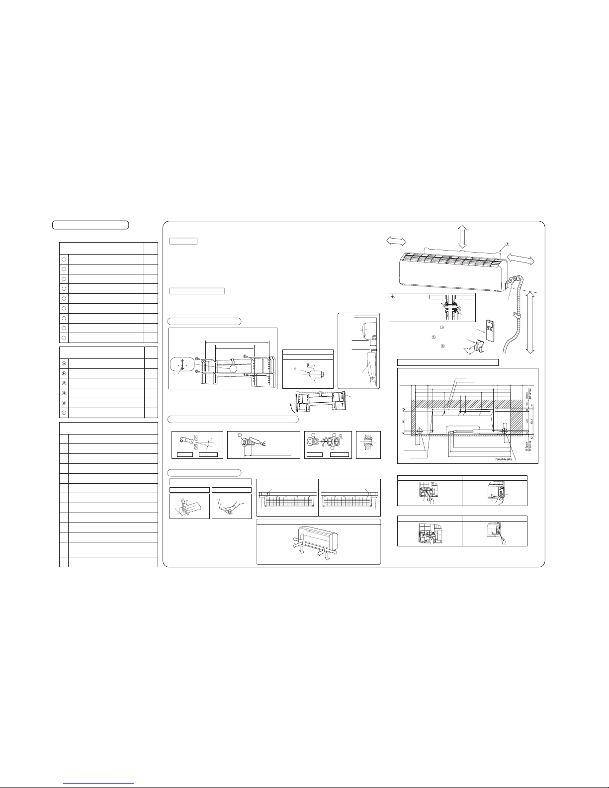
• This installation manual illustrates the method of installing an indoor unit.
• For electrical wiring work, see instructions set out on the backside.
• For outdoor unit installation and refrigerant piping, refer to page 26.
• A wired remote control unit is supplied separately as an option part.
• While installing the unit, be sure to check the selection of installation place,
power source specifications, usage limitation (piping length, height
differences between indoor and outdoor units, power source voltage etc.)
and installation spaces.
8. APPLICATION DATA
(1) Installation of indoor unit
-
23
-
'15 • SRK-T-175
Necessary tools for the installation work
1
2
3
4
5
6
7
8
9
10
11
12
13
1
1
1
1
1
1
Q’ty
Locally procured parts
Sealing plate
Sleeve
Inclination plate
Putty
Drain hose (extension hose)
Piping cover
(for insulation of connection piping)
Plus headed driver
Knife
Saw
Tape measure
Hammer
Spanner wrench
Torque wrench
Hole core drill (65mm in diameter)
Wrench key (Hexagon) [4m/m]
Flaring tool set
Gas leak detector
Pipe bender
Gauge for projection adjustment
Used when flare is made by using
conventional flare tool
( )
( )
14.0 ~ 82.0N·m
(1.4 ~ 8.2kgf·m)
(
Designed specifically
for R410A
)
BEFORE INSTALLATION
○ Before installation check that the power source matches the
air-conditioner.
R410A REFRIGERANT USED
WALL TYPEAIR-CONDITIONER
INSTALLATION MANUAL FOR INDOOR UNIT
RLD012A001
1
1
1
10
2
2
2
Q’ty
Standard accessories (Installation kit)
Accessories for indoor unit
Installation board
(Attached to the rear of the indoor unit)
Wireless remote control
Remote control holder
Battery [R03 (AAA, Micro) 1.5V]
Air-cleaning filters
2
1
Insulation (#486 50 x 100 t3)
Filter holders
Tapping screws
(for installation board ø4 X 25mm)
Wood screws
(for remote control holder ø3.5 X 16mm)
1
2
3
4
5
6
7
8
9
( )
Designed specifically
for R410A
INSTALLATION SPACE (INDOOR UNIT)
(FRONT VIEW)
Relation between setting plate and indoor unit
5 cm minimum
from the wall
15 cm minimum
from the wall
Installation board
Sleeve (sold separately)
10 cm minimum from the ceiling
[Drain hose changing procedures]
1. Remove the drain hose 2. Remove the drain cap.
○Remove it with hand or pliers.○Remove the screw and drain hose,
making it rotate.
3. Insert the drain cap. 4. Connect the drain hose.
○Insert the drain cap which was removed
at procedure “2” securely using a
hexagonal wrench etc.
Note: Be careful that If it is not inserted
securely, water leakage may occur.
○Insert the drain hose securely, making
rotate. And install the screw.
Note: Be careful that If it is not inserted
securely, water leakage may occur.
CAUTION
Completely seal the hole on
the wall with putty. Otherwise,
furniture, or other, may be
wetted by leaked water or
dewing.
putty
putty
Indoor side Outdoor side
Piping in the left direction
Piping in the right rear directionPiping in the left rear direction
Piping in the right direction
Piping is possible in the rear, left, left rear, left downward, right or downward direction.
Right
Rear
Downward
Left
rear
Left downward
Left
Installing the support of piping
In case of piping in the right rear direction
Sufficient care must be taken not to damage
the panel when connecting pipes.
[Top view]
When drilling the wall that contains a metal lath, wire lath or metal plate, be sure to use pipe hole sleeve sold separately.
• Matters of special notice when piping from left or central/rear of the unit.
Left-hand-side piping Right-hand-side piping
Drilling of hole and fixture of sleeve (Locally procured parts)
Shaping of pipings Taping of the exterior
Pipings
Drain hose
Top
Thickness of the wall + 1.5cm
5
ø65
Indoor side Outdoor side
Indoor side Outdoor side Installed state
Turn to
tighten
b
b
c
a
○In case of rear piping draw out, cut off the lower
and the right side portions of the sleeve collar.
○Drill a hole with whole core drill.
○Hold the bottom of the
piping and fix direction
before stretching it and
shaping it.
○Tape only the portion that
goes through the wall.
○Always tape the wiring
with the piping.
180 cm minimum from the floor
screw
cap
(Unit : mm)
SELECTION OF INSTALLATION LOCATION
INSTALLATION OF INDOOR UNIT
Indoor unit
(Install at location that meets the following conditions, after getting approval from the customer)
○ Where there is no obstructions to the air flow and where the cooled and heated air can be evenly distributed.
○ A solid place where the unit or the wall will not vibrate.
○ A place where there will be enough space for servicing. (Where space mentioned below can be secured)
○ Where wiring and the piping work will be easy to conduct.
○ The place where receiving part is not exposed to the direct rays of the sun or the strong rays of the street lighting.
○ A place where it can be easily drained.
○ A place separated at least 1m away from the television or the radio. (To prevent interference to images and sounds.)
○ Places where this unit is not affected by the high frequency equipment or electric equipment.
○ Avoid installing this unit in place where there is much oil mist.
○ Places where there is no electric equipment or household under the installing unit.
○ Install the indoor unit on the wall where the height from the floor to the bottom of the unit is more than 1.8m.
Wireless remote control
○ A place where the air-conditioner can be received the signal surely during operating the wireless remote control.
○ Places where there is no affected by the TV and radio etc.
○ Do not place where exposed to direct sunlight or near heat devices such as a stove.
Installation of Installation board
Fixing on concrete wall
Use of nut anchor
Bolt
(M6 12)
Standard
hole
Installation
sample
Indoor unit
Obstacle such
as curtain
Be sure that the flap
of outlet should not
touch any obstacles.
for service
Indoor unit
768
157
214.5 214.5
883 157
53.5
77
15050
Piping for Liquid 780
Installation board
60
470 363.5363.5
568.5 568.5
Space
for service
Space
and nut anchor
For bolt anchor
Piping hole (ø65)
Drain hose 759 (ø16)
Piping for Gas
715 (SRK24/71/80/92/100, DXK24/28/32)
709 (SRK63, DXK21)
○Adjustment of the installation board in the horizontal direction is
to be conducted with eight screws in a temporary tightened state.
○Adjust so the board will be level by turning the board with the
standard hole as the center.
13
cm
Wireless remote control
Remote control holder
Wood screws
Look for the inside wall structures (Intermediate support or pillar
and firmly install the unit after level surface has been checked.)
768
410
Mating mark for
level surface
WARNING
• Installation must be carried out by the qualified installer.
If you install the system by yourself, it may cause serious trouble such as
water leaks, electric shocks, fire and personal injury, as a result of a
system malfunction. Do not carry out the installation and maintenance
work except the by qualified installer.
• Install the system in full accordance with the installation manual.
Incorrect installation may cause bursts, personal injury, water leaks,
electric shocks and fire.
• Be sure to use only for household and residence.
If this appliance is installed in inferior environment such as machine shop
and etc., it can cause malfunction.
• Use the original accessories and the specified components for
installation.
If parts other than those prescribed by us are used, It may cause water
leaks, electric shocks, fire and personal injury.
• Install the unit in a location with good support.
Unsuitable installation locations can cause the unit to fall resulting in
material damage and personal injury.
• Ventilate the working area well in the event of refrigerant leakage
during installation.
If the refrigerant comes into contact with naked flames, poisonous gas is
produced.
• When installing in small rooms, take prevention measures not to
exceed the density limit of refrigerant in the event of leakage,
referred by the formula (accordance with ISO5149).
If the density of refrigerant exceeds the limit, consult the dealer and
install the ventilation system, otherwise lack of oxygen can occur, which
can cause serious accident.
• After completing installation, check that no refrigerant leaks from
the system.
If refrigerant leaks into the room and comes into contact with an oven or
other hot surface, poisonous gas is produced.
• Use the prescribed pipes, flare nuts and tools for R410A.
Using existing parts (for R22 or R407C) can cause the unit failure and
serious accidents due to burst of the refrigerant circuit.
• Tighten the flare nut by torque wrench with specified method.
If the flare nuts were tightened with excess torque, this may cause burst
and refrigerant leakage after a long period.
• The electrical installation must be carried out by the qualified
electrician in accordance with “the norm for electrical work” and
“national wiring regulation”, and the system must be connected to
the dedicated circuit.
Power source with insufficient capacity and incorrect function done by
improper work can cause electric shocks and fire.
• Be sure to shut off the power before starting electrical work.
Failure to shut off the power can cause electric shocks, unit failure or
incorrect function of equipment.
• Be sure to use the cables conformed to safety standard and cable
ampacity for power distribution work.
Unconformable cables can cause electric leak, anomalous heat
production or fire.
• This appliance must be connected to main power source by means
of a circuit breaker or switch [fuse Model 63(21):16A, Model 71(24),
80(28), 92, 100:20A] with a contact separation of at least 3mm.
• When plugging this appliance, a plug conforming to the norm
IEC60884-1 must be used.
• Use the prescribed cables for electrical connection, tighten the
cables securely in terminal block and relieve the cables correctly to
prevent overloading the terminal blocks.
Loose connections or cable mountings can cause anomalous heat
production or fire.
• Arrange the wiring in the control box so that it cannot be pushed up
further into the box. Install the service panel correctly.
Incorrect installation may result in overheating and fire.
• Be sure to switch off the power source in the event of installation,
inspection or servicing.
If the power source is not shut off, there is a risk of electric shocks, unit
failure or personal injury due to the unexpected start of fan.
• Be sure to wear protective goggles and gloves while at work.
• Earth leakage breaker must be installed.
If the earth leakage breaker is not installed, it can cause electric shocks.
CAUTION
• Use the circuit breaker of correct capacity. Circuit breaker should be able to
disconnect all poles under over current.
Using the incorrect one could cause the system failure and fire.
• Install isolator or disconnect switch on the power
source
wiring in
accordance with the local codes and regulations.
The isolator should be locked in OFF state in accordance with EN60204-1.
• Be sure to install indoor unit properly according to instruction manual so
that drainage can run off smoothly.
Improper installation of indoor unit can cause dropping water into the room and
damaging personal property.
• Install the drainage pipe to run off drainage securely according to the
installation manual.
Incorrect installation of the drainage pipe can cause dropping water into the room
and damaging personal property.
• Be sure to install the drainage pipe with descending slope of 1/100 or more,
and not to make traps and air-bleedings.
Check if the drainage runs off securely during commissioning and ensure the
space for inspection and maintenance.
• After maintenance, all wiring, wiring ties and the like, should be returned to
their original state and wiring route, and the necessary clearance from all
metal parts should be secured.
• Secure a space for installation, inspection and maintenance specified in the
manual.
Insufficient space can result in accident such as personal injury due to falling
from the installation place.
• Take care when carrying the unit by hand.
If the unit weights more than 20kg, it must be carried by two or more persons. Do
not carry by the plastic straps, always use the carry handle when carrying the unit
by hand. Use gloves to minimize the risk of cuts by the aluminum fins.
• Dispose of any packing materials correctly.
Any remaining packing materials can cause personal injury as it contains nails
and wood. And to avoid danger of suffocation, be sure to keep the plastic
wrapper away from children and to dispose after tear it up.
• For installation work, be careful not to get injured with the heat exchanger,
piping flare portion or screws etc.
• Be sure to insulate the refrigerant pipes so as not to condense the ambient
air moisture on them.
Insufficient insulation can cause condensation, which can lead to moisture
damage on the ceiling, floor, furniture and any other valuables.
• When perform the air-conditioner operation (cooling or dehumidifying
operation) in which ventilator is installed in the room. In this case, using the
air-conditioner in parallel with the ventilator, there is the possibility that
drain water may backflow in accordance with the room lapse into the
negative pressure status. Therefore, set up the opening port such as
incorporate the air into the room that may appropriate to ventilation (For
example; Open the door a little). In addition, just as above, so set up the
opening port if the room lapse into negative pressure status due to register
of the wind for the high rise apartment etc.
• Be sure to perform air tightness test by pressurizing with nitrogen gas after
completed refrigerant piping work.
If the density of refrigerant exceeds the limit in the event of refrigerant leakage in
the small room, lack of oxygen can occur, which can cause serious accidents.
• Do not install the unit in the locations listed below.
• Locations where carbon fiber, metal powder or any powder is floating.
• Locations where any substances that can affect the unit such as sulphide
gas, chloride gas, acid and alkaline can occur.
• Vehicles and ships.
• Locations where cosmetic or special sprays are often used.
• Locations with direct exposure of oil mist and steam such as kitchen and
machine plant.
• Locations where any machines which generate high frequency harmonics
are used.
• Locations with salty atmospheres such as coastlines.
• Locations with heavy snow (If installed, be sure to provide base flame and
snow hood mentioned in the manual).
• Locations where the unit is exposed to chimney smoke.
• Locations at high altitude (more than 1000m high).
• Locations with ammonic atmospheres (e.g. organic fertilizer).
• Locations with calcium chloride (e.g. snow melting agent).
• Locations where heat radiation from other heat source can affect the unit.
• Locations without good air circulation.
• Locations withany obstacleswhich can preventinlet andoutlet air of theunit.
• Locations where short circuit of air can occur (in case of multiple units
installation).
• Locations where strong air blows against the air outlet of outdoor unit.
• Locations where something located above the unit could fall.
It can cause remarkable decrease in performance, corrosion and damage of
components, malfunction and fire.
• Do not install the indoor unit in the locations listed below (Be sure to
install the indoor unit according to the installation manual for each
model because each indoor unit has each limitation).
•
Locations with any obstacles which can prevent inlet and outlet air of the unit.
•
Locations where vibration can be amplified due to insufficient strength of structure.
• Locations where the infrared receiver is exposed to the direct sunlight or
the strong light beam (in case of the infrared specification unit).
• Locations where an equipment affected by high harmonics is placed (TV
set or radio receiver is placed within 1m).
• Locations where drainage cannot run off safely.
It can affect performance or function and etc.
• Do not install the unit near the location where leakage of
combustible
gases can occur.
If leaked gases accumulate around the unit, it can cause fire.
• Do not install the unit where corrosive gas (such as sulfurous acid
gas etc.) or combustible gas (such as thinner and petroleum gases)
can accumulate or collect, or where volatile combustible substances
are handled.
Corrosive gas can cause corrosion of heat exchanger, breakage of plastic
parts and etc. And combustible gas can cause fire.
• Do not use the indoor unit at the place where water splashes may
occur such as in laundries.
Since the indoor unit is not waterproof, it can cause electric shocks and fire.
• Do not install nor use the system close to the equipment that
generates electromagnetic fields or high frequency harmonics.
Equipment such as inverters, standby generators, medical high frequency
equipments and telecommunication equipments can affect the system, and
cause malfunctions and breakdowns. The system can also affect medical
equipment and telecommunication equipment, and obstruct its function or
cause jamming.
• Do not place any variables which will be damaged by getting wet
under the indoor unit.
When the relative humidity is higher than 80% or drainage pipe is clogged,
condensation or drainage water can drop and it can cause the damage of
valuables.
• Do not install the remote control at the direct sunlight.
It can cause malfunction or deformation of the remote control.
•
Do not use the unit for special purposes such as storing foods,
cooling precision instruments and preservation of animals, plants
or art.
It can cause the damage of the items.
• Do not use any materials other than a fuse with the correct rating in
the location where fuses are to be used.
Connecting the circuit with copper wire or other metal thread can cause unit
failure and fire.
• Do not touch any buttons with wet hands.
It can cause electric shocks.
• Do not touch any refrigerant pipes with your hands when the system
is in operation.
During operation the refrigerant pipes become extremely hot or extremely cold
depending the operating condition, and it can cause burn injury or frost injury.
• Do not wash the inside of the air-conditioner.
Water leakage and permanent damage may result.
Electrical hazard exists.
• Carry out the electrical work for ground lead with care.
Do not connect the ground lead to the gas line, water line, lightning conductor or telephone line’s ground lead. Incorrect grounding can cause unit
faults such as electric shocks due to short-circuiting.
• Do not put the drainage pipe directly into drainage channels where
poisonous gases such as sulphide gas can occur.
Poisonous gases will flow into the room through drainage pipe and
seriously affect the user’s health and safety.This can also cause the
corrosion of the indoor unit and a resultant unit failure or refrigerant leak.
• Ensure that no air enters in the refrigerant circuit when the unit is
installed and removed.
If air enters in the refrigerant circuit, the pressure in the refrigerant circuit
becomes too high, which can cause burst and personal injury.
• Do not process or splice the power cord, or share the socket with
other power plugs.
This may cause fire or electric shock due to defecting contact, defecting
insulation and over-current etc.
• Do not bundle or wind or process the power cord. Do not deform
the power cord by treading it.
This may cause fire or heating.
• Do not vent R410A into the atmosphere : R410A is a fluorinated
greenhouse gas, covered by the Kyoto Protocol with Groval
Warming Potential (GWP)=1975.
• Do not run the unit with removed panels or protections.
Touching rotating equipments, hot surfaces or high voltage parts can
cause personal injury due to entrapment, burn or electric shocks.
•
Do not perform any change of protective device itself or its setup
condition.
The forced operation by short-circuiting protective device of pressure
switch and temperature controller or the use of non specified component
can cause fire or burst.
SAFETY PRECAUTIONS
• Before installation, read the “SAFETY PRECAUTIONS” carefully and strictly
follow it during the installation work in order to protect yourself.
• The precautionary items mentioned below are distinguished into two levels,
and .
: Wrong installation would cause serious consequences such
as injuries or death.
: Wrong installation might cause serious consequences
depending on circumstances.
Both mention the important items to protect your health and safety so strictly
follow them by any means.
•
Be sure to confirm no anomaly on the equipment by commissioning after completed
installation and explain the operating methods as well as the maintenance methods
of this equipment to the user according to the owner’s manual.
• Keep the installation manual together with owner’s manual at a place where
any user can read at any time. Moreover if necessary, ask to hand them to a
new user.
• Before starting the installation work, proper precautions (using suitable
protective clothing, groves etc.) should be taken by qualified installer.
• Pay attention not to fall down the tools, etc. when installing the unit at the
high position.
• If unusual noise can be heard during operation, consult the dealer.
• The meanings of “Marks” used here are shown as follows:
Never do it under any
circumstances.
Always do it according to the
instruction.
CAUTION
WARNING
CAUTION
WARNING
• This installation manual illustrates the method of installing an indoor unit.
• For electrical wiring work, see instructions set out on the backside.
• For outdoor unit installation and refrigerant piping, refer to page 26.
• A wired remote control unit is supplied separately as an option part.
• While installing the unit, be sure to check the selection of installation place,
power source specifications, usage limitation (piping length, height
differences between indoor and outdoor units, power source voltage etc.)
and installation spaces.
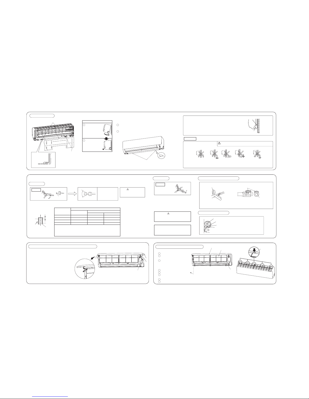
-
24
-
'15 • SRK-T-175
RLD012A001
○ Arrange the drain hose in a downward angle.
○ Avoid the following drain piping.
○ Pour water to the drain pan located under the heat exchanger, and ensure that the water is discharged outdoor.
○ When extended drain hose is present inside the room, insulate it securely with heat insulator available in the market.
CAUTION
Wall
Gutter
Pipe accommodating section
Drainage
yvaWdeificepsnahtrehgiH
Installation Steps
• How to remove the indoor unit from the installation board
Fixing of indoor unit
Push up at the marked portion of the indoor unit base lower latch, and slightly pull it toward
you. (both right and left hand sides) (The indoor unit base lower latch can be removed from
the installation board)
Push up the indoor unit upward so that it can be removed from installation board.
latch
Installation board
Indoor unit base latch
Wall
Go through all installation steps and check if the drainage is all right.
Otherwise water leak may occur.
2
1
2
1
Gently push the lower
part to secure the unit.
Pass the pipe through
the hole in the wall,
and hook the upper
part of the indoor unit
to the installation
board.
Since this air-conditioner has been designed to collect dew drops on the rear
surface to the drain pan, do not attach the power cord above the gutter.
The drain hose
tip is in water.
The gap to the ground is
5 cm or less.
The drain hose
tip is in the gutter.
Odor from
the gutter
Installation board
Indoor unit
Latch (2 locations)
Open/close and detachment/attachment of the air inlet panel
○To open, pull the panel at both ends of lower part and
release latches, then pull up the panel until you feel
resistance.
(The panel stops at approx. 60° open position)
○To close, hold the panel at both ends of lower part to
lower downward and push it slightly until the latch
works.
○To remove, pull up the panel to the position shown in
right illustration and pull it toward you.
○To install, insert the panel arm into the slot on the front
panel from the position shown in right illustration, hold
the panel at both ends of lower part, lower it downward
slowly, then push it slightly until the latch works.
To remove /To install
Approx. 80°
• Flaring work
Measurement B
Flaring
block
Copper pipe
Finishing work and fixing
Connection wiring,
Earth wiring
Outer tape
Refrigerant piping
Drain hose
Wood screw
Clamp
○ Install the removed flared nuts to the pipes to be connected,
then flared the pipes.
○ Remove the flared nuts. (on both liquid and gas sides)
Keep the openings of the pipes covered with tapes etc. to prevent dust, sand, etc. from entering them.
CONNECTION OF REFRIGERANT PIPINGS
Preparation
(Do not turn)
Press
Remove
A
Dimension A
CAUTION
Do not apply refrigerating machine
oil to the flared surface.
Indoor
CAUTION
Do not apply excess torque to the flared nuts.
Otherwise, the flared nuts may crack.
○Connect the pipes on both liquid and gas sides.
○Tighten the nuts to the following torque.
noitropnoitcennocehtfonoitalusnInoitcennoC
Indoor
(Do not turn)
• Cover the indoor unit’s flare-connected joints, after they are checked for a gas leak, with an indoor
unit heat insulating material and then wrap them with a tape with an attached insulation pad placed
over the heat insulating material’s slit area.
Cover the coupling with insulator and then cover it with tapes.
Vinyl tape
Use an attached insulation pad for heat insulation.
Position it so that the slit area faces upward.
Liquid side
Gas side
Cover the exterior portion with outer tape and
shape the piping to match with the contours of
the route that piping will take.
Also fix the wiring and pipings to the wall with
clamps.
Copper pipe diameter
Use a flare tool designed for R410A or a conventional flare tool.
Note that measurement B (protrusion from the flaring block) will vary depending on the type of
a flare tool in use.
If a conventional flare tool is used, use a copper pipe gauge or a similar instrument to check
protrusion so that you can keep measurement B to a correct value.
Clutch type flare tool for
R410A
Conventional (R22) flare tool
ø6.35
ø15.88
0.0 - 0.5
0.0 - 0.5
1.0 - 1.5
1.0 - 1.5
1.5 - 2.0
2.0 - 2.5
ø12.7 0.0 - 0.5 1.0 - 1.5 2.0 - 2.5
ø9.52 0.0 - 0.5 1.0 - 1.5 1.5 - 2.0
Measurement B (mm)
Clutch type Wing nut type
How to remove and install the front panel
Latch
○Removing
○Installing
Remove the air filter.
Cover the unit with the front panel.
Tighten the 8 screws to fix the
front panel.
Install the air filter.
Install the air inlet panel.
Front panel
Air inlet panel
Air filter
Screw
5
4
3
2
1
3
2
1
Remove the air inlet panel.
Remove the 8 screws fixing to the
front panel.
Remove the 5 latches in the upper
section of the front panel and then
remove the front panel from the unit.
If FDC71VNP is connected, use reducer at gas
side of indoor unit to change the pipe size from
ø15.88 to ø12.7. (Reducer is attached in the
outdoor unit accessory)
Liquid sideø6.35 : 9.1 (mm)
ø9.52 : 13.2 (mm)
Gas side ø9.52 : 13.2 (mm)
ø12.7 : 16.6 (mm)
ø15.88 : 19.7 (mm)
Liquid side (ø6.35) : 14.0 - 18.0 N·m (1.4 - 1.8 kgf·m)
(ø9.52) : 34.0 - 42.0 N·m (3.4 - 4.2 kgf·m)
Gas side (ø9.52) : 34.0 - 42.0 N·m (3.4 - 4.2 kgf·m)
(ø12.7) : 49.0 - 61.0 N·m (4.9 - 6.1 kgf·m)
(ø15.88) : 68.0 - 82.0 N·m (6.8 - 8.2 kgf·m)
90 ± 0.5°
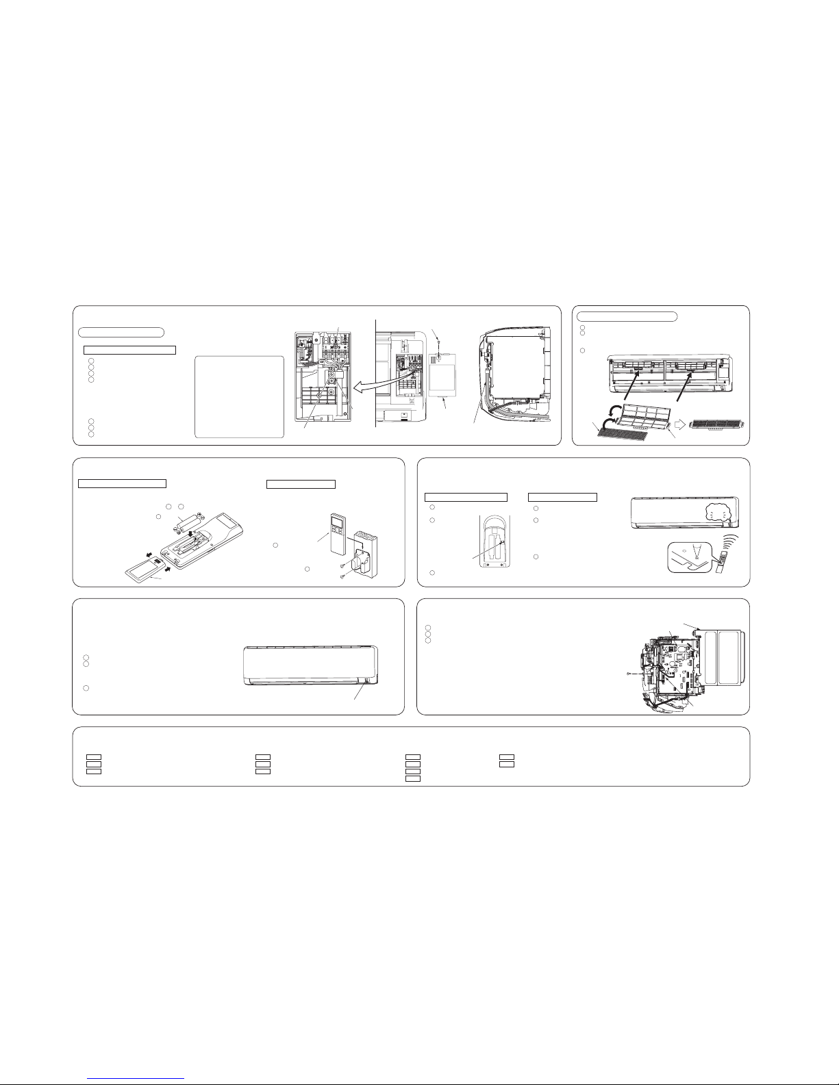
-
25
-
'15 • SRK-T-175
RLD012A001
○ Uncover the wireless remote control, and mount the batteries [R03 (AAA, Micro),
×2 pieces] in the body regularly.
(Fit the poles with the indication marks, + & − without fail)
○ Conventionally, operate the wireless remote control
by holding in your hand.
○ Avoid installing it on a clay wall etc.
Cover
Wood screws
ø3.5 X 16
Wireless remote control
Battery
INSTALLATION OF WIRELESS REMOTE CONTROL
Mounting method of battery
Fixing to pillar or wall
2
6
5
Reception
pip
Disconnect
TIME SETUP ACL
When two air-conditioners are installed in the same room, use this setting when the two air-conditioners are not operated with one
wireless remote control. Set the wireless remote control and indoor unit.
INSTALLING TWO AIR-CONDITIONERS IN THE SAME ROOM
Setting the wireless remote control
Pull out the cover and take out
batteries.
Disconnect the
switching line
next to the
battery with
wire cutters.
Insert batteries. Close the cover.
1
2
3
Setting an indoor unit
1
2
3
INSTALLATION TEST CHECK POINTS
After installation
The power source voltage is correct as the rating.
No gas leaks from the joints of the service valve.
Power cables and crossover wires are securely fixed to
the terminal board.
Test run
Air-conditioning operation is normal.
No abnormal noise.
Water drains smoothly.
Protective functions are not working.
The wireless remote control is normal.
Operation of the unit has been explained to the customer. (Three-minutes restart preventive timer)
When the air-conditioner is restarted or when changing the operation, the unit will not start operating for
approximately 3 minutes. This is to protect the unit and it is not a malfunction.
The screw of the lid is tightened securely.
Service valve is fully open.
The pipe joints for indoor and outdoor pipes
have been insulated.
Check the following points again after completion of the installation, and before turning on the power. Conduct a test run again and ensure that the unit operates properly.
At the same time, explain to the customer how to use the unit and how to take care of the unit following the user’s manual.
Turn off the power
source
, and turn it on after
1 minute.
Point the wireless remote control that was set
according to the procedure described on the
left side at the indoor unit and send a signal by
pressing the ACL switch on the wireless remote control.
Since the signal is sent in about 6 seconds after the ACL switch is
pressed, point the wireless remote control at the indoor unit for some time.
Check that the reception buzzer sound "pip" is emitted from the
indoor unit.
At completion of the setting, the indoor unit emits a buzzer sound
"pip". (If no reception tone is emitted, start the setting from the
beginning again.)
○ Arrange the drain hose in a downward angle.
○ Avoid the following drain piping.
○ Pour water to the drain pan located under the heat exchanger, and ensure that the water is discharged outdoor.
○ When extended drain hose is present inside the room, insulate it securely with heat insulator available in the market.
CAUTION
Wall
Gutter
Pipe accommodating section
Drainage
yvaWdeificepsnahtrehgiH
Installation Steps
• How to remove the indoor unit from the installation board
Fixing of indoor unit
Push up at the marked portion of the indoor unit base lower latch, and slightly pull it toward
you. (both right and left hand sides) (The indoor unit base lower latch can be removed from
the installation board)
Push up the indoor unit upward so that it can be removed from installation board.
latch
Installation board
Indoor unit base latch
Wall
Go through all installation steps and check if the drainage is all right.
Otherwise water leak may occur.
2
1
2
1
Gently push the lower
part to secure the unit.
Pass the pipe through
the hole in the wall,
and hook the upper
part of the indoor unit
to the installation
board.
Since this air-conditioner has been designed to collect dew drops on the rear
surface to the drain pan, do not attach the power cord above the gutter.
The drain hose
tip is in water.
The gap to the ground is
5 cm or less.
The drain hose
tip is in the gutter.
Odor from
the gutter
Installation board
Indoor unit
Latch (2 locations)
Open/close and detachment/attachment of the air inlet panel
○To open, pull the panel at both ends of lower part and
release latches, then pull up the panel until you feel
resistance.
(The panel stops at approx. 60° open position)
○To close, hold the panel at both ends of lower part to
lower downward and push it slightly until the latch
works.
○To remove, pull up the panel to the position shown in
right illustration and pull it toward you.
○To install, insert the panel arm into the slot on the front
panel from the position shown in right illustration, hold
the panel at both ends of lower part, lower it downward
slowly, then push it slightly until the latch works.
To remove /To install
Approx. 80°
• Flaring work
Measurement B
Flaring
block
Copper pipe
Finishing work and fixing
Connection wiring,
Earth wiring
Outer tape
Refrigerant piping
Drain hose
Wood screw
Clamp
○ Install the removed flared nuts to the pipes to be connected,
then flared the pipes.
○ Remove the flared nuts. (on both liquid and gas sides)
Keep the openings of the pipes covered with tapes etc. to prevent dust, sand, etc. from entering them.
CONNECTION OF REFRIGERANT PIPINGS
Preparation
(Do not turn)
Press
Remove
A
Dimension A
CAUTION
Do not apply refrigerating machine
oil to the flared surface.
Indoor
CAUTION
Do not apply excess torque to the flared nuts.
Otherwise, the flared nuts may crack.
○Connect the pipes on both liquid and gas sides.
○Tighten the nuts to the following torque.
noitropnoitcennocehtfonoitalusnInoitcennoC
Indoor
(Do not turn)
• Cover the indoor unit’s flare-connected joints, after they are checked for a gas leak, with an indoor
unit heat insulating material and then wrap them with a tape with an attached insulation pad placed
over the heat insulating material’s slit area.
Cover the coupling with insulator and then cover it with tapes.
Vinyl tape
Use an attached insulation pad for heat insulation.
Position it so that the slit area faces upward.
Liquid side
Gas side
Cover the exterior portion with outer tape and
shape the piping to match with the contours of
the route that piping will take.
Also fix the wiring and pipings to the wall with
clamps.
Copper pipe diameter
Use a flare tool designed for R410A or a conventional flare tool.
Note that measurement B (protrusion from the flaring block) will vary depending on the type of
a flare tool in use.
If a conventional flare tool is used, use a copper pipe gauge or a similar instrument to check
protrusion so that you can keep measurement B to a correct value.
Clutch type flare tool for
R410A
Conventional (R22) flare tool
ø6.35
ø15.88
0.0 - 0.5
0.0 - 0.5
1.0 - 1.5
1.0 - 1.5
1.5 - 2.0
2.0 - 2.5
ø12.7 0.0 - 0.5 1.0 - 1.5 2.0 - 2.5
ø9.52 0.0 - 0.5 1.0 - 1.5 1.5 - 2.0
Measurement B (mm)
Clutch type Wing nut type
How to remove and install the front panel
Latch
○Removing
○Installing
Remove the air filter.
Cover the unit with the front panel.
Tighten the 8 screws to fix the
front panel.
Install the air filter.
Install the air inlet panel.
Front panel
Air inlet panel
Air filter
Screw
5
4
3
2
1
3
2
1
Remove the air inlet panel.
Remove the 8 screws fixing to the
front panel.
Remove the 5 latches in the upper
section of the front panel and then
remove the front panel from the unit.
Open the air inlet panel.
Remove the lid.
Remove the wiring clamp.
Connect the connecting wire securely to the terminal block.
1) Connect the connection wire securely to the terminal
block. If the wire is not affixed completely, contact will be
poor, and it is dangerous as the terminal block may heat
up and catch fire.
2) Take care not to confuse the terminal numbers for indoor
and outdoor connections.
Fix the connecting wire by wiring clamp.
Attach the lid.
Close the air inlet panel.
ELECTRICAL WIRING WORK
Preparation of indoor unit
Mounting of connecting wires
7
6
5
4
3
2
1
Use cables for interconnection wiring to avoid loosening of the wires.
CENELEC code for cables Required field cables.
H05RNR4G1.5 (example) or 245IEC57
H Harmonized cable type
05 300/500 volts
R Natural-and/or synth, rubber wire insulation
N Polychloroprene rubber conductors insulation
R Stranded core
4or5 Number of conductors
G One conductor of the cable is the earth conductor
(yellow/green)
1.5 Section of copper wire (mm
2
)
Terminal block
Wiring
Clamp
Lid
• Earth wire shall be Yellow/Green (Y/G) in color and longer than other AC wires for safety reason.
The screw of the lid is
tightened securely
Connecting wire
• Pass the connecting wire through the path from
the bottom of the control box to the front part as
shown in the illustration.
• Forced cooling operation
Turn off power
source. Turn on power source again after a while. Then, press the
ON/OFF button continuously for at least 5 seconds. (The operation will start.)
TERMINAL CONNECTION FOR AN INTERFACE
Remove the air inlet panel, lid and front panel.
Remove the control cover. (Remove the screw.)
There is a terminal (respectively marked with CNS) for the indoor control board.
In connecting an interface, connect to the respective terminal securely with the connection harness
supplied with an option “Interface connection kit SC-BIKN-E ” and fasten the connection harness
onto the indoor control box with the clamp supplied with the kit.
For more details, refer to the user’s manual of your “Interface connection kit SC-BIKN-E ”.
3
2
1
3
2
1
Connect charge hose to check joint of outdoor unit.
Liquid side : Close the liquid valve with hexagon wrench key.
Gas side : Fully open the gas valve.
Carry out cooling operation. (If indoor temperature is low, operate
forced cooling operation.)
After low pressure gauge become 0.01MPa, stop cooling operation
and close the gas valve.
<How to pump down>
○In order to protect the environment, be sure to pump down (recovery of refrigerant).
○Pump down is the method of recovering refrigerant from the indoor unit to the outdoor
unit when the pipes are removed from the unit.
HOW TO RELOCATE OR DISPOSE OF THE UNIT
Indoor unit PCB
screw
Unit ON/OFF button
Control cover
CNS terminal
Installing the air-cleaning filters
Open the air inlet panel and remove the air filters.
Install the air-cleaning filter in the filter holders, and then install the filter
holders in the air-conditioner.
• Each air-cleaning filter can be installed in the left or right filter holder.
Install the air filters and close the inlet panel.
Filter holder
Air-cleaning
filter
If FDC71VNP is connected, use reducer at gas
side of indoor unit to change the pipe size from
ø15.88 to ø12.7. (Reducer is attached in the
outdoor unit accessory)
○ In case of faulty wiring connection,
indoor unit does not operate. Then,
run lamp turns on and timer lamp
blinks.
○ Do not use new and old batteries
together.
Liquid sideø6.35 : 9.1 (mm)
ø9.52 : 13.2 (mm)
Gas side ø9.52 : 13.2 (mm)
ø12.7 : 16.6 (mm)
ø15.88 : 19.7 (mm)
Liquid side (ø6.35) : 14.0 - 18.0 N·m (1.4 - 1.8 kgf·m)
(ø9.52) : 34.0 - 42.0 N·m (3.4 - 4.2 kgf·m)
Gas side (ø9.52) : 34.0 - 42.0 N·m (3.4 - 4.2 kgf·m)
(ø12.7) : 49.0 - 61.0 N·m (4.9 - 6.1 kgf·m)
(ø15.88) : 68.0 - 82.0 N·m (6.8 - 8.2 kgf·m)
1
2
3
90 ± 0.5°
-
26
-
'15 • SRK-T-175
INSTALLATION MANUAL FOR OUTDOOR UNIT
RCR012A200C
1. HAULAGE AND INSTALLATION (Take particular care in carrying in or moving the unit, and always perform such an operation with two or more persons.)
CAUTION
When a unit is hoisted with slings for haulage, take into consideration the offset of its gravity center position.
If not properly balanced, the unit can be thrown off-balance and fall.
1) Delivery
2) Portage
3) Selecting the installation location
• Deliver the unit as close as possible to the installation site before removing it from
the packaging.
• When you have to unpack the unit for a compelling reason before you haul it to
the installation point, hoist the unit with nylon slings or ropes and protection pads
so that you may not damage the unit.
• The right hand side of the unit as viewed from the front (Fan side) is heavier. A
person carrying the right hand side must take heed of this fact. A person
carrying the left hand side must hold with his right hand the handle provided on
the front panel of the unit and with his left hand the corner column section.
Be sure to select a suitable installation place in consideration of following conditions.
• A place where it is horizontal, stable and can endure the unit weight and will not allow vibration transmittance
of the unit.
• A place where it can be free from possibility of bothering neighbors due to noise or exhaust air from the unit.
• A place where the unit is not exposed to oil splashes.
• A place where it can be free from danger of flammable gas leakage.
• A place where drain water can be disposed without any trouble.
• A place where the unit will not be affected by heat radiation from other heat source.
• A place where snow will not accumulate.
• A place where the unit can be kept away 1m or more from TV set and/or radio receiver in order to avoid any
TV set or radio receiver interference.
• A place where good air circulation can be secured, and enough service space can be secured for maintenance
and service of the unit safely.
• A place where the unit will not be affected by electromagnetic waves and/or high-harmonic waves generated
by other equipment.
• A place where chemical substances like sulfuric gas, chloric gas, acid and alkali (including ammonia), which
can harm the unit, will not be generated and not remain.
• If a operation is conducted when the outdoor air temperature is -5 or lower, the outdoor unit should be
installed at a place where it is not influenced by natural wind.
• A place where strong wind will not blow against the outlet air blow of the unit.
• A place where stringent regulation of electric noises is not applicable.
Note as a unit designed for R410A
• Do not use any refrigerant other than R410A. R410A will rise to pressure about 1.6 times higher than that of a conventional refrigerant.
A cylinder containing R410A has a pink indication mark on the top.
• A unit designed for R410A has adopted a different size indoor unit service valve charge port and a different size check joint provided in the unit to prevent the charging of a wrong refrigerant by mistake.
The processed dimension of the flared part of a refrigerant pipe and a flare nut’s parallel side measurement have also been altered to raise strength against pressure.
Accordingly, you are required to arrange dedicated R410A tools listed in the table on the left before installing or servicing this unit.
• Do not use a charge cylinder. The use of a charge cylinder will cause the refrigerant composition to change, which results in performance degradation.
• In charging refrigerant, always take it out from a cylinder in the liquid phase.
• All indoor units must be models designed exclusively for R410A. Check connectable indoor unit models in a catalog, etc. (A wrong indoor unit, if connected into the system, will impair proper system operation)
• Before installation, read the “SAFETY PRECAUTIONS” carefully and strictly follow it during the installation work
in order to protect yourself.
• The precautionary items mentioned below are distinguished into two levels, and .
: Wrong installation would cause serious consequences such as injuries or death.
: Wrong installation might cause serious consequences depending on circumstances.
Both mention the important items to protect your health and safety so strictly follow them by any means.
• Be sure to confirm no anomaly on the equipment by commissioning after completing installation and explain
the operating methods as well as the maintenance methods of this equipment to the user according to the
owner’s manual.
• Keep the installation manual together with owner’s manual at a place where any user can read at any time.
Moreover if necessary, ask to hand them to a new user.
• Before starting the installation work, proper precautions (using suitable protective clothing, groves etc.) should
be taken by qualified installer.
• Pay attention not to fall down the tools, etc. when installing the unit at the high position.
• If unusual noise can be heard during operation, consult the dealer.
• The meanings of “Marks” used here are shown as follows:
• This installation manual deals with outdoor units and general installation specifications only. For indoor units, refer to page 22.
• While install the unit, be sure to check the selection of installation place, power source specifications, usage limitation (piping length, height differences between indoor and outdoor units, power source
voltage etc.) and installation spaces.
SAFETY PRECAUTIONS
WARNING
Never do it under any circumstances. Always do it according to the instruction.
CAUTIONWARNING
CAUTION
WARNING
• Installation must be carried out by the qualified installer.
If you install the system by yourself, it may cause serious trouble such as water leaks,
electric shocks, fire and personal injury, as a result of a system malfunction. Do not
carry out the installation and maintenance work except the by qualified installer.
• Install the system in full accordance with the installation manual.
Incorrect installati on may cau se bursts, personal injury, water leaks, electric
shocks and fire.
• Be sure to use only for household and residence.
If this appliance is installed in inferior e nvironment such as machine shop etc., it
can cause malfunction.
• When installing in small rooms, take prevention measures not to
exceed the density limit of refrigerant in the event of leakage, referred
by the formula (accordance with ISO5149).
If the density of refrigerant exceeds the limit, consult the dealer and install the
ventilation system, other wise lack of oxygen can occur, which can cause serious
accident.
• Use the original accessories and the specified components for
installation.
If parts other than those prescribed by us are used, It may cause water leaks,
electric shocks, fire and personal injury.
• Install the unit in a location with good support.
Unsuitable installation locations can cause the unit to fall resulting in material
damage and personal injury.
• Ensure the unit is stable when installed, so that it can withstand
earthquakes and strong winds.
Unsuitable installation locations can cause the unit to fall and cause material
damage and personal injury.
• Ventilate the working area well in the event of refrigerant leakage during
installation.
If the refrigerant comes into contact with naked flames, poisonous gas is produced.
• Use the prescribed pipes, flare nuts and tools for R410A.
Using existing parts (for R22 or R407C) can cause the unit failure and serious
accidents due to burst of the refrigerant circuit.
• Tighten the flare nuts by torque wrench with specified method.
If the flare nut were tightened with excess torque, this may cause burst and
refrigerant leakage after a long period.
• Do not open the service valves for liquid line and gas line until
completed refrigerant piping work, air tightness test and evacuation.
If the compressor is operated in state of opening se rvice valves before completin g
connection of refrigerant pi ping work, air can be sucked into refrigerant circuit,
which can cause bust or personal injury due to a nomalously high pressure in the
refrigerant.
• The electrical installation must be carried out by the qualified electrician
in accordance with “the norm for electrical work” and “national wiring
regulation”,and the system must be connected to the dedicated circuit.
Power source with insufficient capacity and incorrect function done by improper
work can cause electric shocks and fire.
• Be sure to shut off the power before starting electrical work.
Failure to shut off the power can cause electric shocks, unit failure or incorrect
function of equipment.
• Be sure to use the cables conformed to safety standard and cable
ampacity for power distribution work.
Unconformable cables can cause electric leak, anomalous heat production or fire.
• This appliance must be connected to main power source by means of a
circuit breaker or switch [fuse Model 63(21):16A, Model 71(24),
80(28):20A] with a contact separation of at least 3mm.
• Arrange the wiring in the control box so that it cannot be pushed up
further into the box. Install the service panel correctly.
Incorrect installation may result in overheating and fire.
• Use the prescribed cables for electrical connection, tighten the cables
securely in terminal block and relieve the cables correctly to prevent
overloading the terminal blocks.
Loose connections or cable mountings can cause anomalous heat production or fire.
• Be sure to fix up the service panels.
Incorrect fixing can cause electric shocks or fire due to intrusion of dust or water.
• Be sure to switch off the power source in the event of installation,
inspection or servicing.
If the power source is not shut off, there is a risk of electric shocks, unit failure or
personal injury due to the unexpected start of fan.
• Stop the compressor before removing the pipe after shutting the
service valve on pump down work.
If the pipe is removed when the compressor is in operation with the service valve
open, air would be mixed in the refrigeration circuit and it could cause explosion
and injuries due to abnormal high pressure in the cooling cycle.
• Only use prescribed option parts. The installation must be carried out
by the qualified installer.
If you install the system by yourself, it can cause serious trouble such as water
leaks, electric shocks, fire.
• Be sure to wear protective goggles and gloves while at work.
• Earth leakage breaker must be installed.
If the earth leakage breaker is not installed, it can cause electric shocks.
• Ensure that no air enters in the refrigerant circuit when the unit is
installed and removed.
If air enters in the refrigerant c ircuit, the pressure in the refrigerant circuit
becomes too high, which can cause burst and personal injury.
•
Do not processor splice the powercord, or share the socketwith other powerplugs.
This may cause fire or electric shock due to defecting contact, defecting insulation
and over-current etc.
• Do not bundle or wind or process the power cord. Do not deform the
power cord by treading it.
This may cause fire or heating.
• Do not run the unit with removed panels or protections.
Touching rotating equipments, hot surfaces or high voltage parts can cause
personal injury due to entrapment, burn or electric shocks.
• Do not perform any change of protective device itself or its setup
condition.
The forced operation by short-circuiting protective device of pressure switch and
temperature controller or the use of non specified component can cause fire or
burst.
Model 63(21)·71(24)·80(28
)
R410A REFRIGERANT USED
(2) Installation of outdoor unit
 Loading...