

Mitsubishi Heavy Industries SRK25ZSX-S, SRK35ZSX-S, SRK20ZS-SB, SRK25ZS-SB, SRK20ZS-S Technical Manual
...
Manual No.'17•SRK-T-203
updated April 10, 2017
TECHNICAL MANUAL
INVERTER WALL MOUNTED TYPE
RESIDENTIAL AIR-CONDITIONERS
(Split system, air to air heat pump type)
SRK20ZSX-S
25ZSX-S
35ZSX-S
50ZSX-S
60ZSX-S

'17 • SRK-T-203
'10 • SRK-T-105
CONTENTS
1. SPECIFICATIONS ........................................................................................ 3
2. EXTERIOR DIMENSIONS
......................................................................... 8
(1) Indoor units .......................................................................................... 8
(2) Outdoor units ....................................................................................... 9
(3) Remote control
..................................................................................... 11
3. ELECTRICAL WIRING .............................................................................. 13
(1) Indoor units .......................................................................................... 13
(2) Outdoor units ....................................................................................... 14
4. NOISE LEVEL ............................................................................................ 16
5. PIPING SYSTEM ...................................................................................... 21
6. RANGE OF USAGE & LIMITATIONS
7. CAPACITY TABLES
8. APPLICATION DATA
................................................................................... 24
.................................................................................. 26
..................................................... 22
(1) Installation of indoor unit ...................................................................... 26
(2) Installation of outdoor unit .................................................................. 30
9. OUTLINE OF OPERATION CONTROL BY MICROCOMPUTER ............... 34
(1) Operation control function by wireless remote control
(2) Unit ON/OFF button
........................................................................... 35
....................... 34
......................................................................... 35(3) Auto restart function
(4) Installing two air-conditioners in the same room
............................... 35
(5) Selection of the annual cooling function .............................................. 36
(6) Heating only function ........................................................................... 36
(7) High power operation ........................................................................... 36
(8) Economy operation
.............................................................................. 37
(9) Airflow direction adjustment .................................................................... 37
(10) 3D auto operation
(11) Timer operation
........................................................................... 38
.................................................................................. 39
(12) Silent operation .................................................................................... 40
(13) Night setback operation
..................................................................... 40
(14) Airflow range setting ........................................................................... 40
(15) Display brightness adjustment
(16) Auto OFF operation
............................................................................ 41
............................................................... 41
(17) Outline of heating operation
(18) Outline of cooling operation
(19) Outline of dehumidifying (DRY) opertaion
(20) Outline of automatic operation
(21) Protective control function
............................................................... 41
............................................................... 43
........................................... 43
............................................................... 44
................................................................... 44
-
-
1

'17 • SRK-T-203
'13 • SRK-T-135
10. MAINTENANCE DATA
(1) Cautions
............................................................................................. 51
............................................................................... 51
(2) Items to check before troubleshooting ................................................. 51
(3) Troubleshooting procedure
(4) Troubleshooting procedure (If the air-conditioner runs)
(5) Self-diagnosis table ............................................................................. 53
(If the air-conditioner does not run at all)
..................... 52
(6) Service mode (Trouble mode access function) ................................... 54
(7) Inspection procedures corresponding to detail of trouble .................... 62
Phenomenon observed after shortcircuit, wire breakage on sensor
(8)
(9) Checking the indoor electrical equipment
........................................... 67
......... 67
(10) How to make sure of wireless remote control ...................................... 69
(11) Inspection procedure for blown fuse on the indoor and outdoor PCB .... 69
(12) Outdoor unit inspection points .............................................................. 70
11. INDOOR UNIT DISASSEMBLY PROCEDURE
12. OPTION PARTS
(1) Wired remote control (RC-E5)
(2) Interface kit (SC-BIKN-E)
........................................................................................... 79
.............................................................. 79
..................................................................... 85
............................................ 73
(3) Superlink E board (SC-ADNA-E) .......................................................... 89
........ 51
13. TECHNICAL INFORMATION
■How to read the model name
Example: SRK 20 Z
SX-S
....................................................................... 91
Series code
Inverter type
Product capacity (Cooling capacity : 2.0kW)
Model name SRK : Wall mounted type
SRC : Outdoor unit
-
-
2

'17 • SRK-T-203
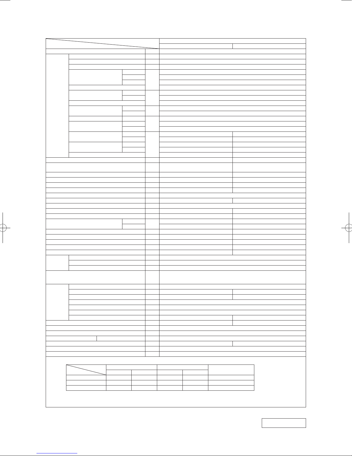
1. SPECIFICATIONS
Item
Power source 1 Phase, 220 - 240V, 50Hz / 220V, 60Hz
Operation
data
Exterior dimensions (Height x Width x Depth) mm 305 x 920 x 220 640 x 800 (+71) x 290
Exterior appearance
(Equivalent color)
Net weight kg 13 43.0
Compressor type & Quantity — RMT5111MCE2(Twin rotary type) x 1
Compressor motor (Starting method) kW — 0.75 (Inverter driven)
Refrigerant oil (Amount, type) ℓ — 0.35 (DIAMOND FREEZE MA68)
Refrigerant (Type, amount, pre-charge length) kg R410A 1.45 in outdoor unit (Incl. the amount for the piping of 15m)
Heat exchanger Louver fins & inner grooved tubing M fins & inner grooved tubing
Refrigerant control Capillary tubes + Electronic expansion valve
Fan type & Quantity Tangential fan x 1 Propeller fan x 1
Fan motor (Starting method) W 42 x1 (Direct drive) 34 x1 (Direct drive)
Air flow
Available external static pressure Pa 0 0
Outside air intake Not possible —
Air filter, Quality / Quantity Polypropylene net (Washable) x 2 —
Shock & vibration absorber Rubber sleeve (for fan motor)
Electric heater — —
Operation
control
Safety equipments
Installation
data
Drain pump, max lift height mm — —
Recommended breaker size A 16
L.R.A. (Locked rotor ampere) A 2.5
Interconnecting wires Size x Core number 1.5mm
IP number IPX0 IPX4
Standard accessories
Option parts Interface kit (SC-BIKN-E)
Nominal cooling capacity (range) kW 2.0 ( 0.9(Min.) - 3.2 (Max.))
Nominal heating capacity (range) kW 2.7 ( 0.8(Min.) - 5.3 (Max.))
Heating capacity (H2) kW —
Power consumption
Max power consumption 1.92
Running current
Inrush current, max current 2.5 Max. 9
Power factor
EER Cooling 6.25
COP
Sound power level
Sound pressure level
Silent mode sound pressure level — Cooling:33 / Heating:38
Remote control Wireless - remote control
Room temperature control Microcomputer thermostat
Operation display RUN: Green, TIMER: Yellow, ECO: Blue
Refrigerant piping size (O.D) mm Liquid line: φ6.35 (1/4") Gas line: φ9.52 (3/8")
Connecting method Flare connection Flare connection
Attached length of piping m Liquid line : 0.55 / Gas line : 0.48 —
Insulation for piping Necessary (Both sides), independent
Refrigerant line (one way) length m Max.25
Vertical height diff. between O.U. and I.U. m Max.15 (Outdoor unit is higher) / Max.15 (Outdoor unit is lower)
Drain hose Hose connectable (VP 16) Holes φ20 x 5 pcs
Cooling
Heating 0.47 (0.14 - 1.36)
Heating (H2) —
Cooling
Heating 2.6 / 2.5 / 2.4 (220/ 230/ 240V)
Cooling
Heating 81
Heating 5.74
Heating (H2) —
Cooling
Heating 53 58
Cooling Hi: 38 Me: 31 Lo: 24 ULo: 19 43
Heating Hi: 38 Me: 32 Lo: 25 ULo: 19 44
Cooling
Heating Hi: 12.2 Me: 10.3 Lo: 7.2 ULo: 5.4 31.0
Model
kW
A
%
dB(A)
3
m
/min
Indoor unit SRK20ZSX-S Outdoor unit SRC20ZSX-S
53 56
Munsell : (8.0Y 9.3/0.1), RAL : 9003
Hi: 11.3 Me: 9.1 Lo: 6.0 ULo: 5.0 31.0
Frost protection, Serial signal error protection, Indoor fan motor error protection,
Heating overload protection( High pressure control ), Cooling overload protection
Mounting kit, Clean filter (Allergen clear filter x 1, Photocatalytic washable deodorizing filter x 1)
Fine snow
Compressor overheat protection, Overcurrent protection,
2
x 4 cores (Including earth cable) / Terminal block (Screw fixing type)
Notes (1) The data are measured at the following conditions.
Indoor air temperature Outdoor air temperature
Operation
Cooling 27˚C 19˚C 35˚C 24˚C ISO5151-T1
Heating 20˚C — 7˚C 6˚C ISO5151-H1
Heating (H2) 20˚C — 2˚C 1˚C ISO5151-H2
(2) This air-conditioner is manufactured and tested in conformity with the ISO.
(3) Sound level indicates the value in an anechoic chamber. During operation these values are somewhat higher due to ambient conditions.
(4) Select the breaker size according to the own national standard.
Item
DB WB DB WB
SRK20ZSX-S
0.32 (0.16 - 0.74)
1.9 / 1.8 / 1.7 (220/ 230/ 240V)
76
Munsell : (4.2Y 7.5/1.1), RAL : 7004
Rubber sleeve (for fan motor & compressor)
The pipe length is 5m.
Standards
Stucco white
RWA000Z269
-
-
3

'17 • SRK-T-203
Item
Power source 1 Phase, 220 - 240V, 50Hz / 220V, 60Hz
Operation
data
Exterior dimensions (Height x Width x Depth) mm 305 x 920 x 220 640 x 800 (+71) x 290
Exterior appearance
(Equivalent color)
Net weight kg 13 43.0
Compressor type & Quantity — RMT5111MCE2(Twin rotary type) x 1
Compressor motor (Starting method) kW — 0.75 (Inverter driven)
Refrigerant oil (Amount, type) ℓ — 0.35 (DIAMOND FREEZE MA68)
Refrigerant (Type, amount, pre-charge length) kg R410A 1.45 in outdoor unit (Incl. the amount for the piping of 15m)
Heat exchanger Louver fins & inner grooved tubing M fins & inner grooved tubing
Refrigerant control Capillary tubes + Electronic expansion valve
Fan type & Quantity Tangential fan x 1 Propeller fan x 1
Fan motor (Starting method) W 42 x1 (Direct drive) 34 x1 (Direct drive)
Air flow
Available external static pressure Pa 0 0
Outside air intake Not possible —
Air filter, Quality / Quantity Polypropylene net (Washable) x 2 —
Shock & vibration absorber Rubber sleeve (for fan motor)
Electric heater — —
Operation
control
Safety equipments
Installation
data
Drain pump, max lift height mm — —
Recommended breaker size A 16
L.R.A. (Locked rotor ampere) A 3.0
Interconnecting wires Size x Core number 1.5mm
IP number IPX0 IPX4
Standard accessories
Option parts Interface kit (SC-BIKN-E)
Nominal cooling capacity (range) kW 2.5 ( 0.9(Min.) - 3.7 (Max.))
Nominal heating capacity (range) kW 3.2 ( 0.8(Min.) - 5.8 (Max.))
Heating capacity (H2) kW —
Power consumption
Max power consumption 1.92
Running current
Inrush current, max current 3.0 Max. 9
Power factor
EER Cooling 5.68
COP
Sound power level
Sound pressure level
Silent mode sound pressure level — Cooling:35 / Heating:39
Remote control Wireless - remote control
Room temperature control Microcomputer thermostat
Operation display RUN: Green, TIMER: Yellow, ECO: Blue
Refrigerant piping size (O.D) mm Liquid line: φ6.35 (1/4") Gas line: φ9.52 (3/8")
Connecting method Flare connection Flare connection
Attached length of piping m Liquid line : 0.55 / Gas line : 0.48 —
Insulation for piping Necessary (Both sides), independent
Refrigerant line (one way) length m Max.25
Vertical height diff. between O.U. and I.U. m Max.15 (Outdoor unit is higher) / Max.15 (Outdoor unit is lower)
Drain hose Hose connectable (VP 16) Holes φ20 x 5 pcs
Cooling
Heating 0.59 (0.14 - 1.54)
Heating (H2) —
Cooling
Heating 3.2 / 3.0 / 2.9 (220/ 230/ 240V)
Cooling
Heating 85
Heating 5.42
Heating (H2) —
Cooling
Heating 56 58
Cooling Hi: 39 Me: 33 Lo: 25 ULo: 19 44
Heating Hi: 40 Me: 34 Lo: 27 ULo: 19 45
Cooling
Heating Hi: 12.8 Me: 11.0 Lo: 7.8 ULo: 5.4 31.0
Model
kW
A
%
dB(A)
3
m
/min
Indoor unit SRK25ZSX-S Outdoor unit SRC25ZSX-S
55 57
Munsell : (8.0Y 9.3/0.1), RAL : 9003
Hi: 12.2 Me: 10.0 Lo: 6.7 ULo: 5.0 31.0
Frost protection, Serial signal error protection, Indoor fan motor error protection,
Heating overload protection( High pressure control ), Cooling overload protection
Mounting kit, Clean filter (Allergen clear filter x 1, Photocatalytic washable deodorizing filter x 1)
Fine snow
Compressor overheat protection, Overcurrent protection,
2
x 4 cores (Including earth cable) / Terminal block (Screw fixing type)
Notes (1) The data are measured at the following conditions.
Indoor air temperature Outdoor air temperature
Operation
Cooling 27˚C 19˚C 35˚C 24˚C ISO5151-T1
Heating 20˚C — 7˚C 6˚C ISO5151-H1
Heating (H2) 20˚C — 2˚C 1˚C ISO5151-H2
(2) This air-conditioner is manufactured and tested in conformity with the ISO.
(3) Sound level indicates the value in an anechoic chamber. During operation these values are somewhat higher due to ambient conditions.
(4) Select the breaker size according to the own national standard.
Item
DB WB DB WB
SRK25ZSX-S
0.44 (0.16 - 0.89)
2.5 / 2.4 / 2.3 (220/ 230/ 240V)
80
Munsell : (4.2Y 7.5/1.1), RAL : 7004
Rubber sleeve (for fan motor & compressor)
The pipe length is 5m.
Standards
Stucco white
RWA000Z269
-
-
4
'17 • SRK-T-203
Item
Power source 1 Phase, 220 - 240V, 50Hz / 220V, 60Hz
Operation
data
Exterior dimensions (Height x Width x Depth) mm 305 x 920 x 220 640 x 800(+71) x 290
Exterior appearance
(Equivalent color)
Net weight kg 13 43.0
Compressor type & Quantity — RMT5111MCE2(Twin rotary type) x 1
Compressor motor (Starting method) kW — 0.90 (Inverter driven)
Refrigerant oil (Amount, type) ℓ — 0.35 (DIAMOND FREEZE MA68)
Refrigerant (Type, amount, pre-charge length) kg R410A 1.45 in outdoor unit (Incl. the amount for the piping of 15m)
Heat exchanger Louver fins & inner grooved tubing M fins & inner grooved tubing
Refrigerant control Capillary tubes + Electronic expansion valve
Fan type & Quantity Tangential fan x 1 Propeller fan x 1
Fan motor (Starting method) W 42 x1 (Direct drive) 34 x1 (Direct drive)
Air flow
Available external static pressure Pa 0 0
Outside air intake Not possible —
Air filter, Quality / Quantity Polypropylene net (Washable) x 2 —
Shock & vibration absorber Rubber sleeve (for fan motor)
Electric heater — —
Operation
control
Safety equipments
Installation
data
Drain pump, max lift height mm — —
Recommended breaker size A 16
L.R.A. (Locked rotor ampere) A 4.3
Interconnecting wires Size x Core number 1.5mm
IP number IPX0 IPX4
Standard accessories
Option parts Interface kit (SC-BIKN-E)
Nominal cooling capacity (range) kW 3.5 ( 0.9(Min.) - 4.3 (Max.))
Nominal heating capacity (range) kW 4.3 ( 0.8(Min.) - 6.6 (Max.))
Heating capacity (H2) kW —
Power consumption
Max power consumption 1.92
Running current
Inrush current, max current 4.3 Max. 9
Power factor
EER Cooling 4.49
COP
Sound power level
Sound pressure level
Silent mode sound pressure level — Cooling:38 / Heating:43
Remote control Wireless - remote control
Room temperature control Microcomputer thermostat
Operation display RUN: Green, TIMER: Yellow, ECO: Blue
Refrigerant piping size (O.D) mm Liquid line: φ6.35 (1/4") Gas line: φ9.52 (3/8")
Connecting method Flare connection Flare connection
Attached length of piping m Liquid line : 0.55 / Gas line : 0.48 —
Insulation for piping Necessary (Both sides), independent
Refrigerant line (one way) length m Max.25
Vertical height diff. between O.U. and I.U. m Max.15 (Outdoor unit is higher) / Max.15 (Outdoor unit is lower)
Drain hose Hose connectable (VP 16) Holes φ20 x 5 pcs
Cooling
Heating 0.90 (0.14 - 1.89)
Heating (H2) —
Cooling
Heating 4.4 / 4.3 / 4.1 (220/ 230/ 240V)
Cooling
Heating 92
Heating 4.78
Heating (H2) —
Cooling
Heating 58 62
Cooling Hi: 43 Me: 35 Lo: 26 ULo: 19 48
Heating Hi: 41 Me: 35 Lo: 28 ULo: 19 47
Cooling
Heating Hi: 13.9 Me: 11.8 Lo: 8.6 ULo: 5.4 31.0
Model
kW
A
%
dB(A)
3
m
/min
Indoor unit SRK35ZSX-S Outdoor unit SRC35ZSX-S
58 61
Munsell : (8.0Y 9.3/0.1), RAL : 9003
Hi: 13.1 Me: 10.8 Lo: 7.3 ULo: 5.0 36.0
Frost protection, Serial signal error protection, Indoor fan motor error protection,
Heating overload protection( High pressure control ), Cooling overload protection
Mounting kit, Clean filter (Allergen clear filter x 1, Photocatalytic washable deodorizing filter x 1)
Fine snow
Compressor overheat protection, Overcurrent protection,
2
x 4 cores (Including earth cable) / Terminal block (Screw fixing type)
Notes (1) The data are measured at the following conditions.
Indoor air temperature Outdoor air temperature
Operation
Cooling 27˚C 19˚C 35˚C 24˚C ISO5151-T1
Heating 20˚C — 7˚C 6˚C ISO5151-H1
Heating (H2) 20˚C — 2˚C 1˚C ISO5151-H2
(2) This air-conditioner is manufactured and tested in conformity with the ISO.
(3) Sound level indicates the value in an anechoic chamber. During operation these values are somewhat higher due to ambient conditions.
(4) Select the breaker size according to the own national standard.
Item
DB WB DB WB
SRK35ZSX-S
0.78 (0.16 - 1.26)
3.9 / 3.7 / 3.6 (220/ 230/ 240V)
91
Munsell : (4.2Y 7.5/1.1), RAL : 7004
Rubber sleeve (for fan motor & compressor)
The pipe length is 5m.
Standards
Stucco white
RWA000Z269
-
-
5

'17 • SRK-T-203
Item
Power source 1 Phase, 220 - 240V, 50Hz / 220V, 60Hz
Operation
data
Exterior dimensions (Height x Width x Depth) mm 305 x 920 x 220 640 x 800 (+71) x 290
Exterior appearance
(Equivalent color)
Net weight kg 13 45
Compressor type & Quantity — RMT5113MCE2(Twin rotary type) x 1
Compressor motor (Starting method) kW — 1.50 (Inverter driven)
Refrigerant oil (Amount, type) ℓ — 0.45 (DIAMOND FREEZE MA68)
Refrigerant (Type, amount, pre-charge length) kg R410A 1.50 in outdoor unit (Incl. the amount for the piping of 15m)
Heat exchanger Louver fins & inner grooved tubing M fins & inner grooved tubing
Refrigerant control Capillary tubes + Electronic expansion valve
Fan type & Quantity Tangential fan x 1 Propeller fan x 1
Fan motor (Starting method) W 42 x1 (Direct drive) 34 x1 (Direct drive)
Air flow
Available external static pressure Pa 0 0
Outside air intake Not possible —
Air filter, Quality / Quantity Polypropylene net (Washable) x 2 —
Shock & vibration absorber Rubber sleeve (for fan motor)
Electric heater — —
Operation
control
Safety equipments
Installation
data
Drain pump, max lift height mm — —
Recommended breaker size A 16
L.R.A. (Locked rotor ampere) A 5.0
Interconnecting wires Size x Core number 1.5mm
IP number IPX0 IPX4
Standard accessories
Option parts Interface kit (SC-BIKN-E)
Nominal cooling capacity (range) kW 5.0 ( 1.0(Min.) - 5.8 (Max.))
Nominal heating capacity (range) kW 6.0 ( 0.6(Min.) - 8.1 (Max.))
Heating capacity (H2) kW —
Power consumption
Max power consumption 2.90
Running current
Inrush current, max current 5.0 Max. 15
Power factor
EER Cooling 3.85
COP
Sound power level
Sound pressure level
Silent mode sound pressure level — Cooling:42 / Heating:43
Remote control Wireless - remote control
Room temperature control Microcomputer thermostat
Operation display RUN: Green, TIMER: Yellow, ECO: Blue
Refrigerant piping size (O.D) mm Liquid line: φ6.35 (1/4") Gas line: φ12.7 (1/2" )
Connecting method Flare connection Flare connection
Attached length of piping m Liquid line : 0.55 / Gas line : 0.48 —
Insulation for piping Necessary (Both sides), independent
Refrigerant line (one way) length m Max.30
Vertical height diff. between O.U. and I.U. m Max.20 (Outdoor unit is higher) / Max.20 (Outdoor unit is lower)
Drain hose Hose connectable (VP 16) Holes φ20 x 5 pcs
Cooling
Heating 1.36 (0.18 - 2.43)
Heating (H2) —
Cooling
Heating 6.2 / 6.0 / 5.7 (220/ 230/ 240V)
Cooling
Heating 99
Heating 4.41
Heating (H2) —
Cooling
Heating 62 63
Cooling Hi: 44 Me: 39 Lo: 31 ULo: 22 50
Heating Hi: 46 Me: 41 Lo: 33 ULo: 23 49
Cooling
Heating Hi: 17.3 Me: 14.3 Lo: 9.8 ULo: 6.2 33.0
Model
kW
A
%
dB(A)
3
m
/min
Indoor unit SRK50ZSX-S Outdoor unit SRC50ZSX-S
59 63
Munsell : (8.0Y 9.3/0.1), RAL : 9003
Hi: 14.3 Me: 12.4 Lo: 7.8 ULo: 5.4 39.0
Frost protection, Serial signal error protection, Indoor fan motor error protection,
Heating overload protection( High pressure control ), Cooling overload protection
Mounting kit, Clean filter (Allergen clear filter x 1, Photocatalytic washable deodorizing filter x 1)
Fine snow
Compressor overheat protection, Overcurrent protection,
2
x 4 cores (Including earth cable) / Terminal block (Screw fixing type)
Notes (1) The data are measured at the following conditions.
Indoor air temperature Outdoor air temperature
Operation
Cooling 27˚C 19˚C 35˚C 24˚C ISO5151-T1
Heating 20˚C — 7˚C 6˚C ISO5151-H1
Heating (H2) 20˚C — 2˚C 1˚C ISO5151-H2
(2) This air-conditioner is manufactured and tested in conformity with the ISO.
(3) Sound level indicates the value in an anechoic chamber. During operation these values are somewhat higher due to ambient conditions.
(4) Select the breaker size according to the own national standard.
Item
DB WB DB WB
SRK50ZSX-S
1.30 (0.19 - 1.80)
6.0 / 5.7 / 5.5 (220/ 230/ 240V)
99
Munsell : (4.2Y 7.5/1.1), RAL : 7004
Rubber sleeve (for fan motor & compressor)
The pipe length is 5m.
Standards
Stucco white
RWA000Z269
-
-
6

'17 • SRK-T-203
Item
Power source 1 Phase, 220 - 240V, 50Hz / 220V, 60Hz
Operation
data
Exterior dimensions (Height x Width x Depth) mm 305 x 920 x 220 640 x 800(+71) x 290
Exterior appearance
(Equivalent color)
Net weight kg 13 45
Compressor type & Quantity — RMT5113MCE2(Twin rotary type) x 1
Compressor motor (Starting method) kW — 1.50 (Inverter driven)
Refrigerant oil (Amount, type) ℓ — 0.45 (DIAMOND FREEZE MA68)
Refrigerant (Type, amount, pre-charge length) kg R410A 1.50 in outdoor unit (Incl. the amount for the piping of 15m)
Heat exchanger Louver fins & inner grooved tubing M fins & inner grooved tubing
Refrigerant control Capillary tubes + Electronic expansion valve
Fan type & Quantity Tangential fan x 1 Propeller fan x 1
Fan motor (Starting method) W 42 x1 (Direct drive) 34 x1 (Direct drive)
Air flow
Available external static pressure Pa 0 0
Outside air intake Not possible —
Air filter, Quality / Quantity Polypropylene net (Washable) x 2 —
Shock & vibration absorber Rubber sleeve (for fan motor)
Electric heater — —
Operation
control
Safety equipments
Installation
data
Drain pump, max lift height mm — —
Recommended breaker size A 16
L.R.A. (Locked rotor ampere) A 5.0
Interconnecting wires Size x Core number 1.5mm
IP number IPX0 IPX4
Standard accessories
Option parts Interface kit (SC-BIKN-E)
Nominal cooling capacity (range) kW 6.1 ( 1.0(Min.) - 6.8 (Max.))
Nominal heating capacity (range) kW 6.8 ( 0.6(Min.) - 8.7 (Max.))
Heating capacity (H2) kW —
Power consumption
Max power consumption 2.90
Running current
Inrush current, max current 5.0 Max. 15
Power factor
EER Cooling 3.37
COP
Sound power level
Sound pressure level
Silent mode sound pressure level — Cooling:42 / Heating:43
Remote control Wireless - remote control
Room temperature control Microcomputer thermostat
Operation display RUN: Green, TIMER: Yellow, ECO: Blue
Refrigerant piping size (O.D) mm Liquid line: φ6.35 (1/4") Gas line: φ12.7 (1/2" )
Connecting method Flare connection Flare connection
Attached length of piping m Liquid line : 0.55 / Gas line : 0.48 —
Insulation for piping Necessary (Both sides), independent
Refrigerant line (one way) length m Max.30
Vertical height diff. between O.U. and I.U. m Max.20 (Outdoor unit is higher) / Max.20 (Outdoor unit is lower)
Drain hose Hose connectable (VP 16) Holes φ20 x 5 pcs
Cooling
Heating 1.67 (0.18 - 2.86)
Heating (H2) —
Cooling
Heating 7.7 / 7.3 / 7.0 (220/ 230/ 240V)
Cooling
Heating 99
Heating 4.07
Heating (H2) —
Cooling
Heating 63 64
Cooling Hi: 46 Me: 41 Lo: 33 ULo: 22 52
Heating Hi: 46 Me: 42 Lo: 34 ULo: 23 52
Cooling
Heating Hi: 17.8 Me: 13.7 Lo: 10.9 ULo: 6.2 39.0
Model
kW
A
%
dB(A)
3
m
/min
Indoor unit SRK60ZSX-S Outdoor unit SRC60ZSX-S
62 65
Munsell : (8.0Y 9.3/0.1), RAL : 9003
Hi: 16.3 Me: 13.4 Lo: 8.9 ULo: 5.4 41.5
Frost protection, Serial signal error protection, Indoor fan motor error protection,
Heating overload protection( High pressure control ), Cooling overload protection
Mounting kit, Clean filter (Allergen clear filter x 1, Photocatalytic washable deodorizing filter x 1)
Fine snow
Compressor overheat protection, Overcurrent protection,
2
x 4 cores (Including earth cable) / Terminal block (Screw fixing type)
Notes (1) The data are measured at the following conditions.
Indoor air temperature Outdoor air temperature
Operation
Cooling 27˚C 19˚C 35˚C 24˚C ISO5151-T1
Heating 20˚C — 7˚C 6˚C ISO5151-H1
Heating (H2) 20˚C — 2˚C 1˚C ISO5151-H2
(2) This air-conditioner is manufactured and tested in conformity with the ISO.
(3) Sound level indicates the value in an anechoic chamber. During operation these values are somewhat higher due to ambient conditions.
(4) Select the breaker size according to the own national standard.
Item
DB WB DB WB
SRK60ZSX-S
1.81 (0.19 - 2.50)
8.3 / 7.9 / 7.6 (220/ 230/ 240V)
99
Munsell : (4.2Y 7.5/1.1), RAL : 7004
Rubber sleeve (for fan motor & compressor)
The pipe length is 5m.
Standards
Stucco white
RWA000Z269
-
-
7
'17 • SRK-T-203
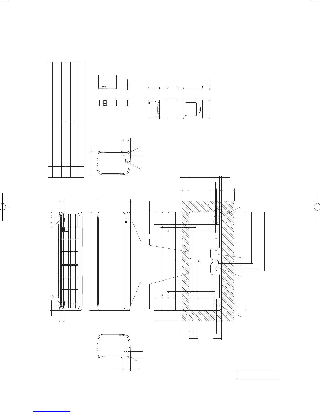
2. EXTERIOR DIMENSIONS
(1) Indoor units
Models SRK20ZSX-S, 25ZSX-S, 35ZSX-S, 50ZSX-S, 60ZSX-S
167
19
Unit:mm
SRK 20,25,35 φ9.52(3/8")(Flare)
Content
Gas piping
A
Symbol
60 45
Wireless remote control
SRK 50,60 φ12.7(1/2")(Flare)
VP16
φ6.35(1/4")(Flare)
(φ65)
(φ65)
Liquid piping
Hole on wall for right rear piping
Hole on wall for left rear piping
Outlet for piping
Drain hose
220 3
B
55
F
ECD
60 24
59.512.5
305
(Option)
Wired remote control
FF
45
Terminal block
100
118.5118.5 683
(Service space)
Unit
□120
10.3277.317.4
65120
(Service space)
□120 19
Notes(1)The model name label is attached
on the right side of the unit.
(2)To connect the wired remote control,
the interface kit(SC-BIKN-E) is required.
56.4
47
(Service space)
533
548
SRK 50,60 486
SRK 20,25,35 480
920
F F
6035
55
Outlet for downward piping
61
59.512.5
(Refer to the top view)
145 630 145
Installation board
100
(Service space)
-
-
8
176 568 176
460 460
48.6
88.6
Space for installation and service when viewing from the front
65 70
D B AE C
47
76.6
RLF000Z201
'17 • SRK-T-203
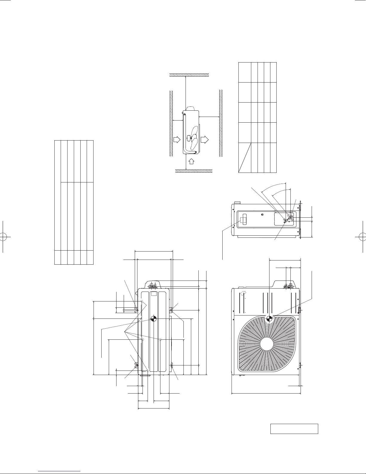
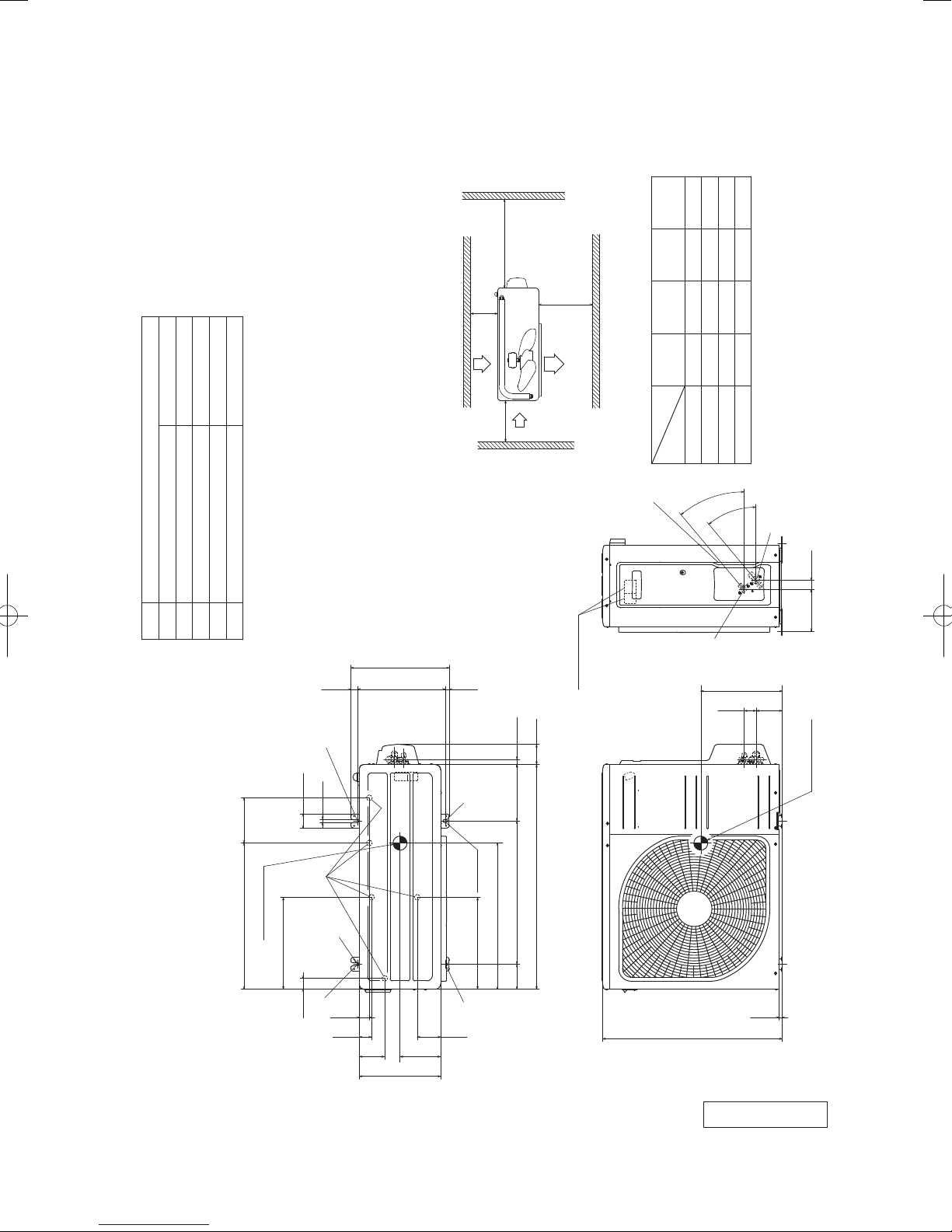
(2) Outdoor units
Models SRC20ZSX-S, 25ZSX-S, 35ZSX-S
φ9.52(3/8")( Flare)
Content
A Service valve connection(Gas side)
Symbol
M10-12×4 places
φ20×5 places
φ6.35(1/4")( Flare)
Drain discharge hole
Service valve connection(Liquid side)
E Anchor bolt hole
D
B
C Pipe/cable draw-out hole
L4
Service
space
( )
Inlet
17.9
L1
Outlet
71.2
L3
Inlet
L2
Notes
( 1) The unit must not be surrounded by walls on the four sides.
( 2) The unit must be fixed with anchor bolts. An anchor bolt must not
protrude more than 15mm.
( 3) If the unit is installed in the location where there is a possibility of
strong winds, place the unit such that the direction of air from the
outlet gets perpendicular to the wind direction.
( 4) Leave 200mm or more space above the unit.
( 5) The wall height on the outlet side should be 1200mm or less.
( 6) The model name label is attached on the right side of the unit.
351.6
24.3312.514.8
Ⅳ
180
Ⅲ
280
280
I Ⅱ
Open
Minimum installation space
installation
L1
Examples
Size
C
Terminal block
Open
Open
75
100
L2
80
80
80
100
L3
40°
Open
Unit:mm
250
Open
250
L4
40°
A
33.5148.4
B
290
93 42.5
12
50.6
520.6 161
Center of gravity
327.3
38.6
E
D E
2-12X16
2-R
E
35.6
43.5
90.6
290
327.3
E
83.5
145
800
Slot hole
520
89 510 201
640
Center of gravity
12.4
RCT000Z019
-
-
9
'17 • SRK-T-203
Model SRC50ZSX-S, 60ZSX-S
φ12.7(1/2")(Flare)
Content
A Service valve connection(Gas side)
Symbol
M10-12×4 places
φ20×5 places
φ6.35(1/4")(Flare)
Service valve connection(Liquid side)
Drain discharge hole
E Anchor bolt hole
D
B
C Pipe/cable draw-out hole
L4
Service
space
( )
L3
Inlet
L2
Notes
(1) The unit must not be surrounded by walls on the four sides.
(2) The unit must be fixed with anchor bolts. An anchor bolt must not
protrude more than 15mm.
(3) If the unit is installed in the location where there is a possibility of
strong winds, place the unit such that the direction of air from the
outlet gets perpendicular to the wind direction.
(4) Leave 200mm or more space above the unit.
(5) The wall height on the outlet side should be 1200mm or less.
(6) The model name label is attached on the front side of the unit.
351.6
24.3312.514.8
E
17.9
L1
Outlet
Inlet
Terminal block
71.2
Ⅳ
Ⅲ
I Ⅱ
Minimum installation space
installation
Examples
Size
C
180
Open
280
Open
75
280
100
Open
L2
L1
40°
40°
80
80
80
100
L3
Open
250
Open
250
L4
B
290
Unit:mm
A
33.5148.4
93 42.5
12
50.6
520.6 161
Center of gravity
327.3
38.6
E
D
2-12X16
2-R
E
35.6
43.5
90.6
290
327.3
E
83.5
145
800
Slot hole
520
89 510 201
640
Center of gravity
12.4
RCT000Z020
-
-
10
'17 • SRK-T-203
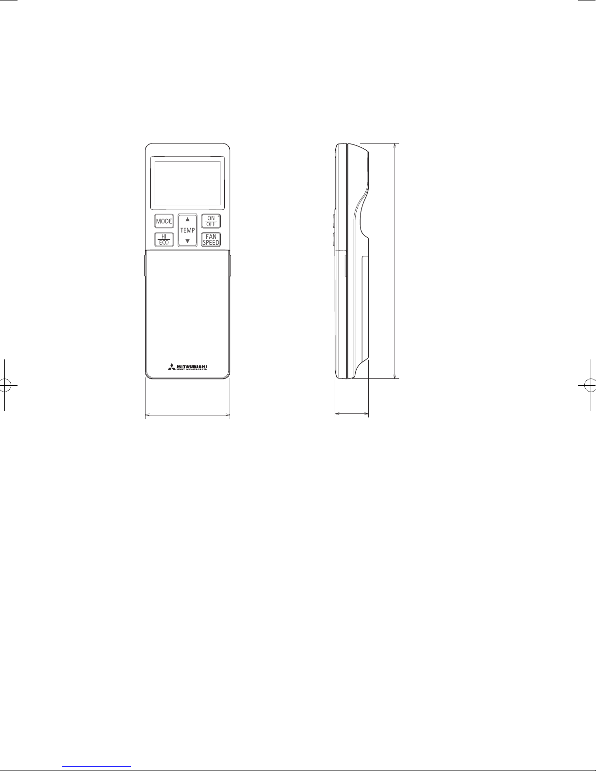
(3) Remote control
(3) Remote control
Wireless remote control
Unit : mm
167
60
26
-
11
-

'17 • SRK-T-203
(b) Wired remote control (option parts)
Interface kit (SC-BIKN-E) is required to use the wired remote control.
Wiring outlet
Cut off the upper thin part of remote control lower case with a nipper or knife,
Exposed mounting
0.3mm2×2 cores.
In case of pulling out
from upper left
L C D
48
In case of pulling out
from center
TEMP ON/OFF
and grind burrs with a file etc.
In case of pulling out
from upper left
Upper
Board
X Y
In case of pulling out
from center
Lower case
Lower part
Sheath
Upper cace
Upper part
Upper
Sheath
Upper cace
Board
YX
X, Y Terminal block
Attach M3 screw
□120
with washer
Pearl whiteExterior appearance
(Munsell color) (N8.5) near equivalent
Embedded mounting
Wall surface
Wiring
Electrical box
(Not included)
19
Remote
control
outline
Wiring oulet
12×7 Slot hole
Lower
In case of pulling out from
The peeling-off length of sheath
Pulling out from upper left
X wiring : 215mm
Y wiring : 195mm
Wiring
upper left
Pulling out from center
X wiring : 170mm
Y wiring : 190mm
Remote control installation dimensions
83.5
120
46
23
44
42
11.5 11
Installation hole
9.5×5 Slot hole (4 places)
Tighten the screws after
cutting off the thin part of
screw mounting part.
120
45
(1) Installation screw for remote control
M4 screw (2 pieces)
Lower
In case of pulling out from center
Wiring
The peeling-off length
of sheath
Unit:mm
Wiring specifications
(1) If the prolongation is over 100m, change to the size below.
But, wiring in the remote control case should be under 0.5mm
the case according to wire connecting. Waterproof treatment is necessary at the wire connecting
section. Be careful about contact failure.
Length Wiring thickness
100 to 200m
Under 300m
Under 400m
Under 600m
0.5mm
0.75mm
1.25mm
2.0mm
2
×2 cores
2
×2 cores
2
×2 cores
2
×2 cores
-
12
2
. Change the wire size outside of
-
PJZ000Z295
'17 • SRK-T-203
3. ELECTRICAL WIRING
(1) Indoor units
Models SRK20ZSX-S, 25ZSX-S, 35ZSX-S, 50ZSX-S, 60ZSX-S
ConnectorCNE
DescriptionItem
CNF
CNG
CNJ
CNL
CNM
CNP
CNS
CNU
CNX
CNY
CNZ
LEFT
MOTOR
LOUVER
M
RIGHT
MOTOR
LOUVER
M
FLAP
MOTOR
M
LEFT
FLAP
LOWER
RIGHT
LOWER
MOTOR
M
FLAP
UPPER
MOTOR
M
INLET
MOTOR
M
LEFT
INLET
MOTOR
M
INLET
RIGHT
SW
LIMIT
PANEL
FAN
MOTOR
M
N
2
1
3
5
DISPLAY
5
CNL
BOARD
CIRCUIT
PRINTED
CNE
7
BACK-UP SW
WIRELESS RECEIVER
5
CNZ
CNX
DIODE
STACK
t
SENSOR
ROOM TEMP.
5
CNG
t
SENSOR 1
HEAT EXCHANGER
5
CNY
CNM
CNF
2
t
HUMIDITY
SENSOR 2
HEAT EXCHANGER
5
CNJ
3
MOTION
SENSOR
5
CNP
CNS
5
INTERFACE KIT
SENSOR
G2
YELLOW/GREEN
RED
WHITE
BLACK
345
1
CNU
FUSE
U
VARISTOR
S/N
WHITE
HEAT
BLUE
YELLOW
6
250V
3.15A
J
L
RED
BLACK
EXCHANGER
Power source
YELLOW/GREEN
N
2
1 3
T
BLOCK
TERMINAL
POWER WIRES
SIGNAL WIRE
EARTH WIRE
[ ]
220V 60Hz
1 Phase
TO OUTDOOR UNIT
220-240V 50Hz
4
HEAT
EXCHANGER
-
13
RWA000Z412
-
'17 • SRK-T-203
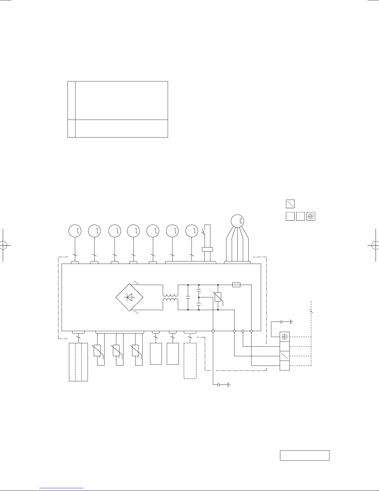
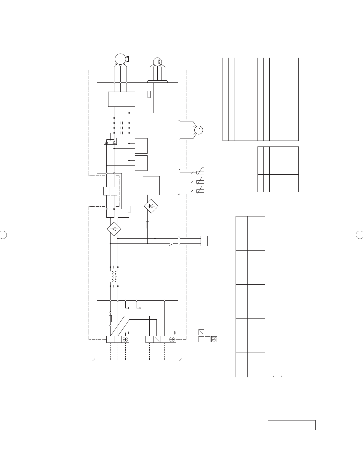
(2) Outdoor units
Models SRC20ZSX-S, 25ZSX-S, 35ZSX-S
CM
MS
3~
(BK)
(WH)
(RD)
U
V
W
UP
V
W
POWER
TRANSISTOR
PCB ASSY PCB1
F2
N
250V 20A
F3
T 1A L 250V
M
(WH)
CNFAN
FMo
+
+
+
DIODE
STACK2
~
L
T1 T2
(YE) (OR)
t゜
NOISE
FILTER
R.IN
(BK)
F7
250V 15A
-
~
PAM
CIRCUIT
F4
250V 10A
+
STACK1
~
+
STACK4
~
F1
C-2
(RD)
-
~
POWER
CIRCUIT
SWITCHING
-
~
t゜
F 3.15A L 250V
G1
(YG)
G2
(YG)
DIODE
DIODE
S.IN
(WH)
(RD)
(WH)
(BK)
CNTH CNEEV
CN20S
M
EEV
t゜
22
TH4TH2 TH3
t゜
t゜
2 2
20S
Item Description
CNEEV
CN20S Connector
20S 4 way valve(coil)
Meaning of marks
Connecting cable
wire size x number*
(m)
Power cable length
wire size x number*(A)
EEV Electric expansion valve(coil)
CM Compressor motor
CNTH
CNFAN
Mark Color
BK Black
Color marks
x 4
2
x 3 22 1.5mm
2
TH4 Discharge pipe temp. sensor
TH3 Outdoor air temp. sensor
TH2 Heat exchanger sensor
L Reactor
FMo Fan motor
Yellow/Green
RD Red
WH White
OR Orange
YE Yellow
YG
3
220V 60Hz
Power source
1 Phase
220-240V 50Hz
TB1
BLOCK
TERMINAL
(BK)
(YG)
3
L 1
N 2
4
]
N
2
1
3
POWER WIRES
SIGNAL WIRE
EARTH WIRE
TO INDOOR UNIT
[
9
MAX running current Power cable
Model name
Power cable, indoor-outdoor connecting wires
SRC20ZSX-S
Switchgear or circuit breaker capacity should be chosen according to national or regional electricity
The power cable specifications are based on the assumption that a metal or plastic conduit is used
with no more than three cables contained in a conduit and a voltage drop is 2%. For an installation
SRC35ZSX-S
SRC25ZSX-S 2.0mm
The wire numbers include earth wire(Yellow/Green)*regulations.
falling outside of these conditions, please follow the national or regional electricity regulations.
RWC000Z297
-
-
14
'17 • SRK-T-203
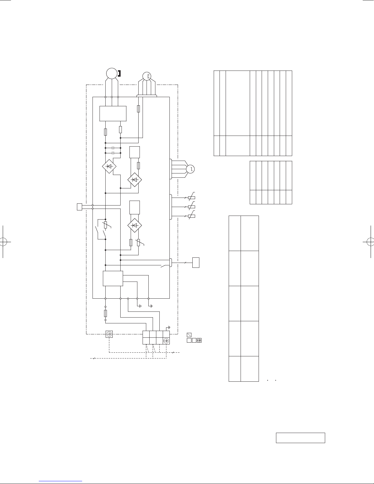
Models SRC50ZSX-S, 60ZSX-S
(RD)
UP
POWER
TRANSISTOR
MS
(WH)
VWU
CM
3~
(BK)
V
W
N
F3
T 1A L 250V
M
(WH)
CNFAN
FMo
+
++
T2
T12
(BL)
(YE)
L1
L2
(BL)
(YE)
T1
T11
+
-
DIODE
STACK1
~
~
PCB ASSY PCB1
F8
PAM
PAM
DIODE
250V 20A
CIRCUIT
CIRCUIT
SWITCHING
+
STACK2
~
F1
POWER
CIRCUIT
-
~
F 3.15A L 250V
(RD)
(WH)
(BK)
CNTH CNEEV
CN20S
M
EEV
Item Description
20S Solenoid coil for 4 way valve
CNFAN
CNEEV
CN20S Connector
EEV Electric expansion valve(coil)
CM Compressor motor
CNTH
TH3 Discharge pipe temp. sensor
TH2 Outdoor air temp. sensor
TH1 Heat exchanger sensor
L1,2 Reactor
FMo Fan motor
Meaning of marks
t゜
t゜
t゜
2 2 2
TH1 TH2 TH3
20S
Connecting cable
Power cable length
Color
BK Black
Mark
Color marks
x 4
2
wire size x number*
(m)
BL Blue
RD Red
YE Yellow
WH White
Yellow/Green
YG
S.IN
R.IN
(BK)
(WH)
F4
250V 20A
(BK)
N
L
TB1
BLOCK 1
TERMINAL
3
220V 60Hz
220-240V 50Hz
Power source
1 Phase
wire size x number*(A)
MAX running current Power cable
Model name
SRC50ZSX-S
x 3 13 1.5mm
2
2.0mm
15
SRC60ZSX-S
Switchgear or circuit breaker capacity should be chosen according to national or regional electricity
The power cable specifications are based on the assumption that a metal or plastic conduit is used
with no more than three cables contained in a conduit and a voltage drop is 2%. For an installation
The wire numbers include earth wire(Yellow/Green)*regulations.
falling outside of these conditions, please follow the national or regional electricity regulations.
G1
G2
(YG)
(YG)
(WH)
(YG)
BLOCK 2
TERMINAL
(BK)
TB2
C-2
(RD)
]
N
N
1
2
(YG)
3
4
2
3
1
POWER WIRES
SIGNAL WIRE
EARTH WIRE
TO INDOOR UNIT
Power cable, indoor-outdoor connecting wires
[
RWC000Z298
-
-
15
'17 • SRK-T-203
Mid octave band frequency (Hz)
N50
N30
N40
N60
N2
Mid octave band frequency (Hz)
N50
N40
N20
N30
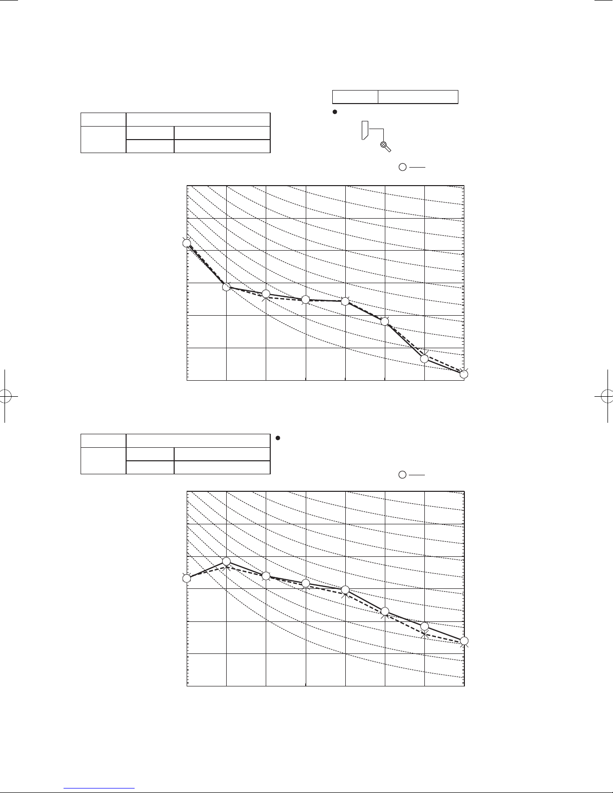
Mike position: at highest noise level in position as mentioned below
Mike position
0.8m
1m
Unit
Mike position
(Center & Low points)
Mike position
4. NOISE LEVEL
Model SRK20ZSX-S
(Indoor Unit)
Model SRK20ZSX-S
Noise
Level
Cooling 38 dB(A)
Heating 38 dB(A)
Condition ISO5151 T1/H1
1m
0.8m
×
......
Unit
Cooling,
Mike position
(Center & Low points)
Heating
70
60
50
Pa)
-5
40
(Standard 2×10
30
Sound pressure level (dB)
20
10
63 125 250 500 1000 2000 4000 8000
(Outdoor Unit)
Model SRC20ZSX-S
Noise
Level
Cooling 43 dB(A)
Heating 44 dB(A)
70
Distance from front side 1m
......
×
Cooling, Heating
70
N70
60
50
40
30
20
0
10
70
N70
60
50
Pa)
-5
40
(Standard 2×10
30
Sound pressure level (dB)
20
10
63 125 250 500 1000 2000 4000 8000
-
16
60
N60
50
40
30
20
10
-
'17 • SRK-T-203
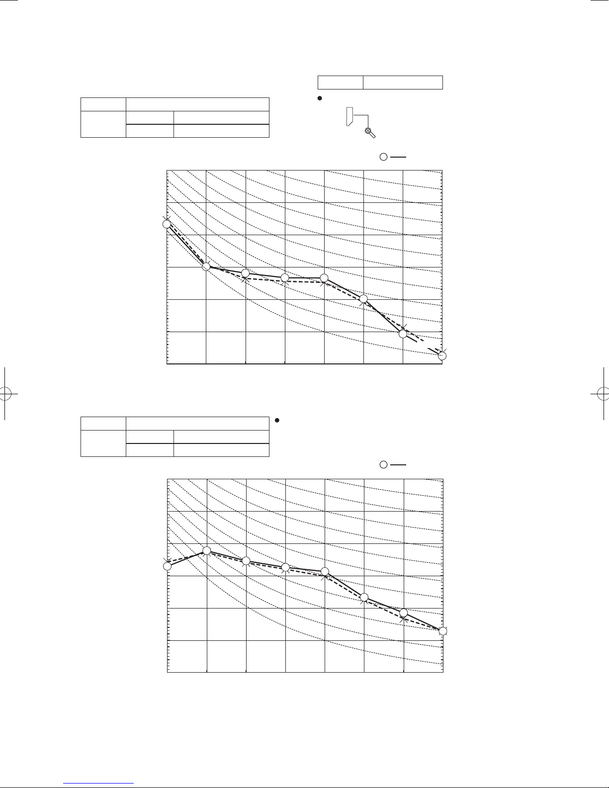
Model SRK25ZSX-S
Mid octave band frequency (Hz)
Mid octave band frequency (Hz)
Mike position: at highest noise level in position as mentioned below
Mike position
0.8m
1m
Unit
Mike position
(Center & Low points)
Mike position
(Indoor Unit)
Model SRK25ZSX-S
Noise
Level
Cooling 39 dB(A)
Heating 40 dB(A)
70
Condition ISO5151 T1/H1
1m
0.8m
×
......
Unit
Cooling,
Mike position
(Center & Low points)
Heating
70
N70
60
50
Pa)
-5
40
(Standard 2×10
30
Sound pressure level (dB)
20
10
63 125 250 500 1000 2000 4000 8000
(Outdoor Unit)
Model SRC25ZSX-S
Noise
Level
Cooling 44 dB(A)
Heating 45 dB(A)
70
Distance from front side 1m
......
×
Cooling, Heating
60
N60
50
N50
40
N40
30
N30
20
N20
10
70
N70
60
50
Pa)
-5
40
(Standard 2×10
30
Sound pressure level (dB)
20
10
63 125 250 500 1000 2000 4000 8000
-
17
60
N60
50
N50
40
N40
30
N30
20
N20
10
-
'17 • SRK-T-203
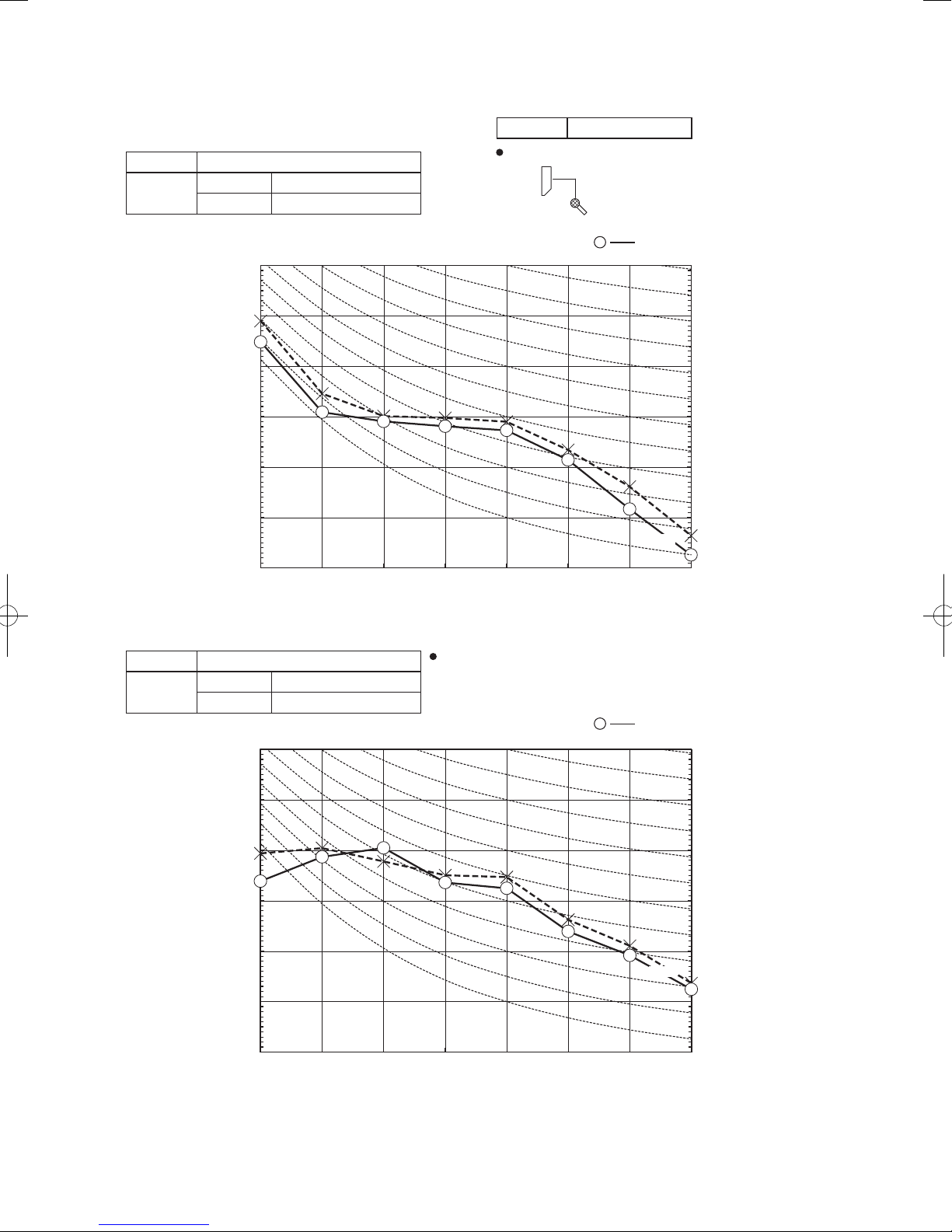
Model SRK35ZSX-S
Mid octave band frequency (Hz)
Mike position: at highest noise level in position as mentioned below
Mike position
0.8m
1m
Unit
Mike position
(Center & Low points)
Mike position
(Indoor Unit)
Model SRK35ZSX-S
Noise
Level
Cooling 43 dB(A)
Heating 41 dB(A)
70
Condition ISO5151 T1/H1
1m
0.8m
×
......
Unit
Cooling,
Mike position
(Center & Low points)
Heating
70
N70
60
50
Pa)
-5
40
(Standard 2×10
30
Sound pressure level (dB)
20
10
63 125 250 500 1000 2000 4000 8000
(Outdoor Unit)
Model SRC35ZSX-S
Noise
Level
Cooling 48 dB(A)
Heating 47 dB(A)
70
Distance from front side 1m
......
×
Cooling,
60
N60
50
N50
40
N40
30
N30
20
N20
10
Heating
70
N70
60
50
Pa)
-5
40
(Standard 2×10
30
Sound pressure level (dB)
20
10
63 125 250 500 1000 2000 4000 8000
Mid octave band frequency (Hz)
-
18
60
N60
50
N50
40
N40
30
N30
20
N20
-
'17 • SRK-T-203
Mike position
Model SRK50ZSX-S
Mike position: at highest noise level in position as mentioned below
Mike position
0.8m
1m
Unit
Mike position
(Center & Low points)
(Indoor Unit)
Model SRK50ZSX-S
Noise
Level
Cooling 44 dB(A)
Heating 46 dB(A)
70
Condition ISO5151 T1/H1
1m
0.8m
×
......
Unit
Cooling,
Mike position
(Center & Low points)
Heating
70
N70
60
50
Pa)
-5
40
(Standard 2×10
30
Sound pressure level (dB)
20
10
63 125 250 500 1000 2000 4000 8000
(Outdoor Unit)
Model SRC50ZSX-S
Noise
Level
Cooling 50 dB(A)
Heating 49 dB(A)
70
Mid octave band frequency (Hz)
Distance from front side 1m
......
×
Cooling,
60
N60
50
N50
40
N40
30
N30
20
N20
10
Heating
70
N70
60
50
Pa)
-5
40
(Standard 2×10
30
Sound pressure level (dB)
20
10
63 125 250 500 1000 2000 4000 8000
Mid octave band frequency (Hz)
-
19
60
N60
50
N50
40
N40
30
N30
20
N20
10
-
'17 • SRK-T-203
Model SRK60ZSX-S
Mid octave band frequency (Hz)
Mid octave band frequency (Hz)
Mike position: at highest noise level in position as mentioned below
Mike position
0.8m
1m
Unit
Mike position
(Center & Low points)
Mike position
(Indoor Unit)
Model SRK60ZSX-S
Noise
Level
Cooling 46 dB(A)
Heating 46 dB(A)
70
Condition ISO5151 T1/H1
1m
0.8m
×
......
Unit
Cooling,
Mike position
(Center & Low points)
Heating
N70
70
60
50
Pa)
-5
40
(Standard 2×10
30
Sound pressure level (dB)
20
10
63 125 250 500 1000 2000 4000 8000
(Outdoor Unit)
Model SRC60ZSX-S
Noise
Level
Cooling 52 dB(A)
Heating 52 dB(A)
70
Distance from front side 1m
......
×
Cooling,
60
N60
50
N50
40
N40
30
N30
20
N20
10
Heating
70
N70
60
50
Pa)
-5
40
(Standard 2×10
30
Sound pressure level (dB)
20
10
63 125 250 500 1000 2000 4000 8000
-
20
60
N60
50
N50
40
N40
30
N30
20
N20
10
-

'17 • SRK-T-203
5. PIPING SYSTEM
Models SRK20ZSX-S, 25ZSX-S, 35ZSX-S
Indoor unit
Room temp.
sensor
(Th1)
Humidity
sensor
(Th3)
Flare
connection
Heat
exchanger
sensor
(Th2
2)
Heat
exchanger
Heat
exchanger
sensor
1)
(Th2
Gas pipe
(φ9.52)
Liquid
pipe
(φ6.35)
Outdoor unit
Service valve
Gas
)
(
Muffler
Check joint
4-way valve
Service valve
(Liquid)
Discharge pipe
temp. sensor
(TH3)
Muffler
Compressor
Electronic
expansion valve
(EEV)
Capillary tube
Cooling cycle
Heating cycle
Accumulator
Capillary tube
Muffler
Outdoor air
temp. sensor
(TH2)
Heat
exchanger
Heat
exchanger
sensor
(TH1)
Flare connection
Models SRK50ZSX-S,60ZSX-S
Indoor unit
Room temp.
sensor
(Th1)
Humidity
sensor
(Th3)
Flare
connection
Heat
exchanger
sensor
(Th2
2)
Heat
exchanger
Heat
exchanger
sensor
1)
(Th2
Gas pipe
(φ12.7)
Liquid
pipe
(φ6.35)
Service valve
Strainer Muffler
Outdoor unit
Gas
)
(
Muffler
Check joint
4-way valve
Service valve
(Liquid)
Muffler
Receiver
Discharge pipe
temp. sensor
(TH3)
Compressor
Electronic
expansion valve
Capillary tube
(EEV)
Cooling cycle
Heating cycle
Accumulator
Capillary tube
Outdoor air
temp. sensor
(TH2)
Heat
exchanger
Heat
exchanger
sensor
(TH1)
Flare connection
Strainer
-
21
Muffler
-
'17 • SRK-T-203
6. RANGE OF USAGE & LIMITATIONS
RANGE OF USAGE & LIMITATIONS
Models
SRK20, 25, 35ZSX-S
SRK50, 60ZSX-S
Item
Indoor return air temperature
(Upper, lower limits)
Outdoor air temperature
(Upper, lower limits)
Refrigerant line (one way) length
Vertical height difference between
outdoor unit and indoor unit
Cooling operation : Approximately 18 to 32℃ D.B.
Heating operation : Approximately 10 to 30℃ D.B.
(Refer to the selection chart)
Cooling operation : Approximately -15 to 46℃ D.B.
Heating operation : Approximately -20 to 24℃ D.B.
(Refer to the selection chart)
Max. 25m Max. 30m
Max. 15m
(Outdoor unit is higher)
Max. 15m
(Outdoor unit is lower)
(Outdoor unit is lower)
Max. 20m
(Outdoor unit is higher)
Max. 20m
Power source voltage Rating ±10%
Voltage at starting Min. 85% of rating
Frequency of ON-OFF cycle
Max. 4 times/h
(Inching prevention 10 minutes)
ON and OFF interval Min. 3 minutes
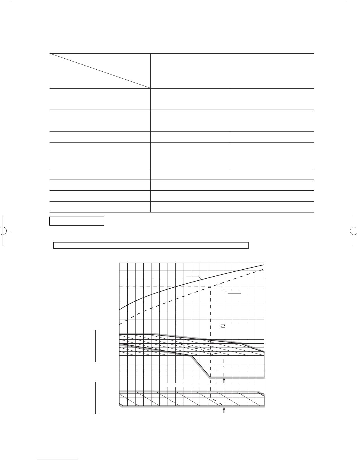
Selection chart
Correct the cooling and heating capacity in accordance with the conditions as follows. The net cooling and heating capacity can be
obtained in the following way.
Net capacity = Capacity shown on specification ×Correction factors as follows.
(1) Coefficient of cooling and heating capacity in relation to temperatures
1.3
&
1.2
1.1
1.0
0.9
0.8
Coefficient of cooling
Heating capacity in
relation to temperature
0.7
0.6
46
40
35
30
°C D. B.
25
temperature
20
Outdoor air D.B.
Cooling operation
0
-5
-10
-15
27
25
20
15
°C D. B.
10
temperature
Indoor air D.B.
Heating operation
Indoor air W.B. temperature °C W.B
-15-20 -10 -5 0 5 10 15
Cooling
Depends on installed situation
.
ISO-T1 Standard Condition
Outdoor air W.B. temperature °C W.B.
ISO-T1 Standard Condition
Heating
Applicable range
26
24
2220181614
-
22
-
'17 • SRK-T-203
'09•SRK-DB-087D
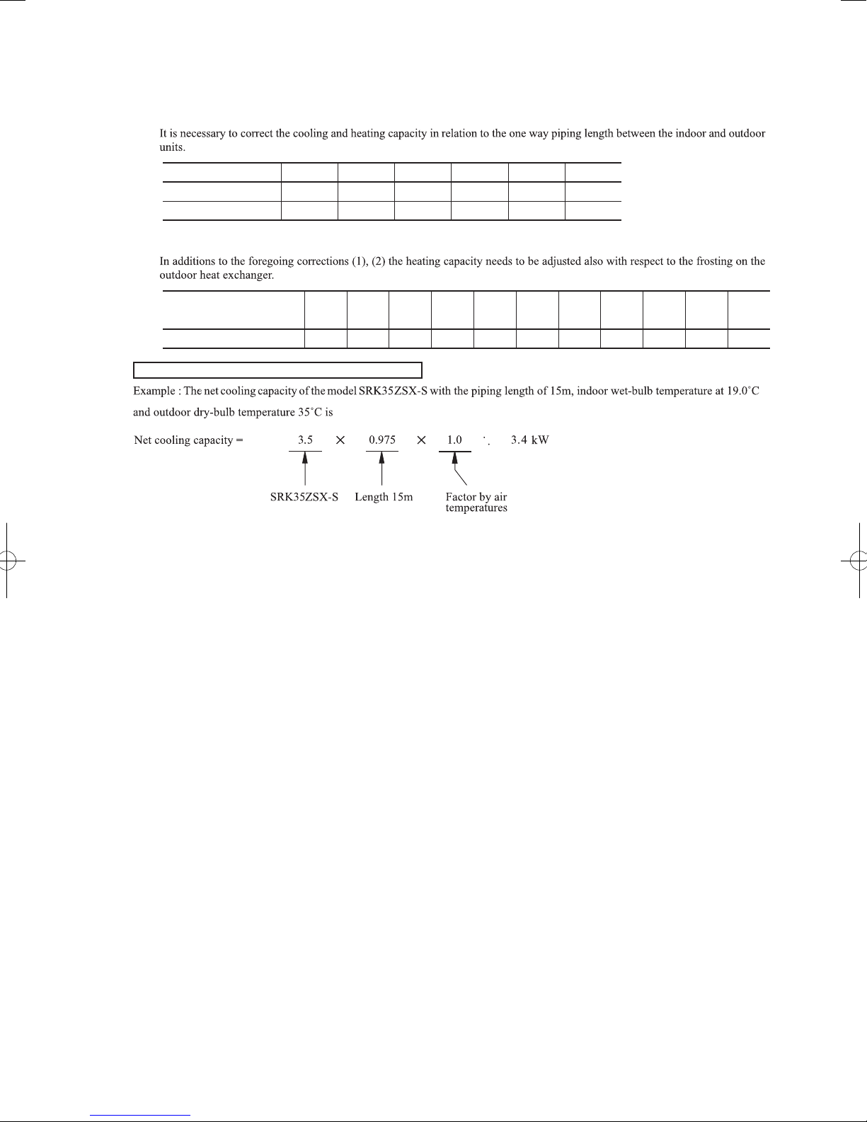
(2) Correction of cooling and heating capacity in relation to one way length of refrigerant piping
Piping length [m]
Cooling
Heating
(3) Correction relative to frosting on outdoor heat exchanger during heating
Air inlet temperature of
outdoor unit in °C WB
Adjustment coefficient
How to obtain the cooling and heating capacity
7
1.0
1.0
-20
0.95 1.00
10
0.99
1.0
-15
0.95 0.95
-10
15
0.975
1.0
20
0.965
1.0
0.94-90.93-70.91-50.88-30.86
=
25
0.95
1.0
30
0.935
1.0
-1 1
0.8730.92
5 or more
-
23
-
'17 • SRK-T-203
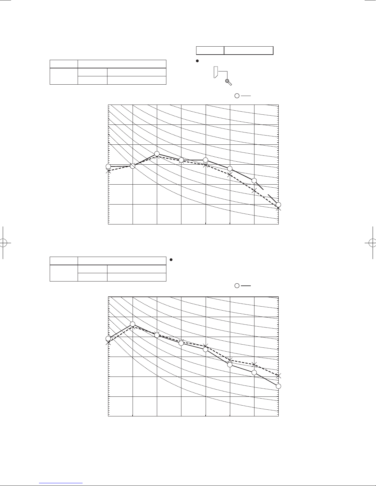
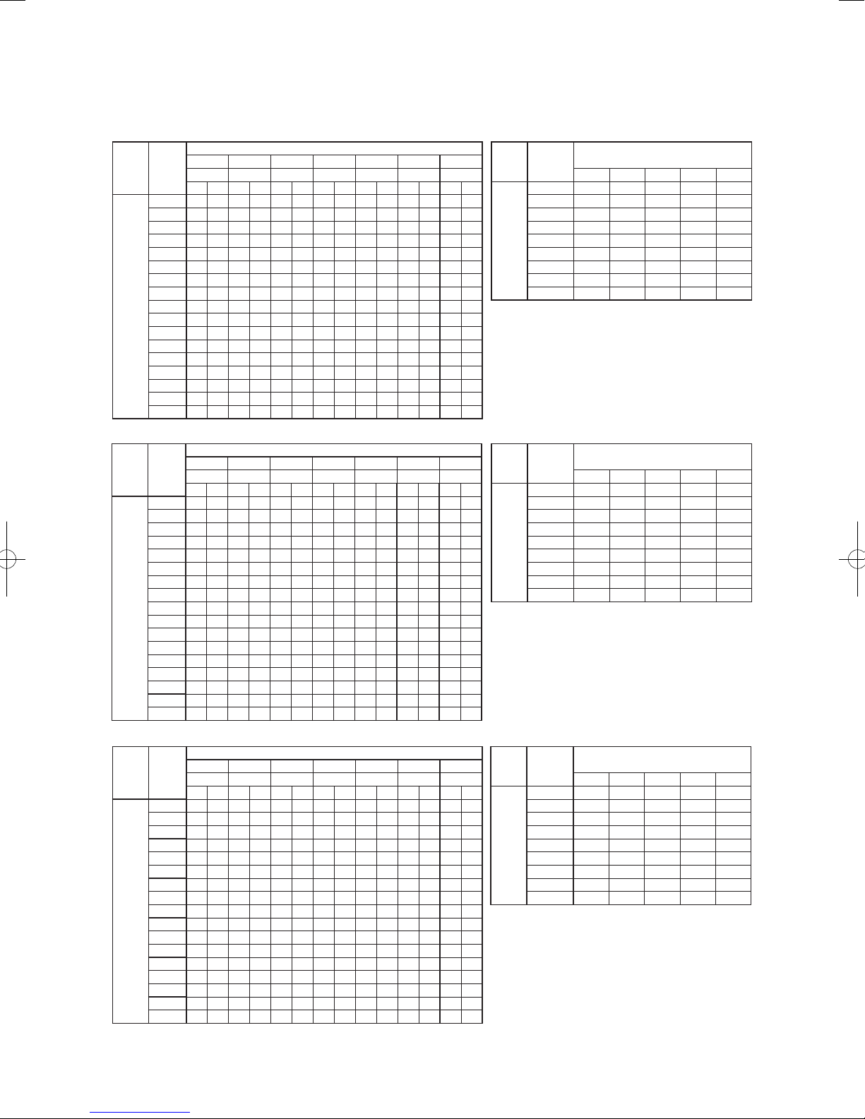
7. CAPACITY TABLES
Model SRK20ZSX-S
Outdoor
Air flow
air temp.
10 2.25 2.12 2.36 2.09 2.45 2.19 2.49 2.17 2.53 2.14 2.60 2.26 2.67 2.21
12 2.21 2.10 2.32 2.07 2.41 2.18 2.45 2.16 2.50 2.14 2.58 2.26 2.65 2.20
14 2.17 2.06 2.28 2.05 2.38 2.17 2.42 2.15 2.47 2.12 2.55 2.24 2.62 2.20
16 2.13 2.02 2.24 2.03 2.34 2.15 2.39 2.13 2.43 2.11 2.52 2.23 2.59 2.17
18 2.08 1.98 2.19 2.01 2.30 2.14 2.35 2.12 2.40 2.10 2.49 2.22 2.56 2.16
20 2.04 1.94 2.15 2.00 2.26 2.13 2.31 2.11 2.36 2.09 2.45 2.20 2.53 2.15
22 1.99 1.89 2.10 1.97 2.22 2.11 2.28 2.10 2.32 2.08 2.42 2.19 2.50 2.14
24 1.94 1.85 2.05 1.95 2.18 2.07 2.24 2.09 2.28 2.07 2.38 2.18 2.47 2.14
Hi
11.3
26 1.90 1.80 2.01 1.91 2.14 2.03 2.20 2.07 2.24 2.05 2.35 2.17 2.43 2.13
3
/min)
(m
28 1.85 1.75 1.96 1.86 2.09 1.99 2.15 2.05 2.20 2.04 2.31 2.16 2.40 2.12
30 1.79 1.70 1.90 1.81 2.05 1.94 2.11 2.01 2.16 2.02 2.27 2.15 2.36 2.11
32 1.74 1.65 1.85 1.76 2.00 1.90 2.07 1.96 2.12 2.00 2.23 2.12 2.32 2.10
34 1.69 1.60 1.80 1.71 1.95 1.85 2.02 1.92 2.07 1.97 2.19 2.08 2.28 2.09
35 1.66 1.58 1.77 1.68 1.93 1.83 2.00 1.90 2.05 1.94 2.17 2.06 2.26 2.08
36 1.63 1.55 1.74 1.65 1.90 1.81 1.98 1.88 2.02 1.92 2.15 2.04 2.24 2.08
38 1.58 1.50 1.68 1.60 1.85 1.76 1.93 1.83 1.98 1.88 2.11 2.00 2.20 2.07
39 1.55 1.47 1.66 1.57 1.83 1.74 1.91 1.81 1.95 1.85 2.08 1.98 2.18 2.06
Model SRK25ZSX-S
Outdoor
Air flow
air temp.
10 2.82 2.64 2.95 2.60 3.06 2.75 3.11 2.72 3.16 2.70 3.26 2.83 3.34 2.76
12 2.77 2.62 2.90 2.58 3.01 2.74 3.07 2.71 3.12 2.68 3.22 2.82 3.31 2.73
14 2.71 2.58 2.85 2.56 2.97 2.71 3.03 2.69 3.08 2.66 3.18 2.80 3.28 2.72
16 2.66 2.53 2.80 2.54 2.92 2.70 2.98 2.67 3.04 2.65 3.15 2.79 3.24 2.71
18 2.60 2.47 2.74 2.52 2.88 2.68 2.94 2.66 2.99 2.63 3.11 2.76 3.20 2.70
20 2.55 2.42 2.68 2.49 2.83 2.66 2.89 2.64 2.95 2.62 3.07 2.75 3.17 2.69
22 2.49 2.37 2.63 2.47 2.78 2.64 2.84 2.62 2.90 2.60 3.02 2.73 3.13 2.68
24 2.43 2.31 2.57 2.44 2.72 2.59 2.80 2.60 2.85 2.58 2.98 2.72 3.08 2.67
Hi
12.2
26 2.37 2.25 2.51 2.38 2.67 2.54 2.74 2.59 2.80 2.56 2.93 2.71 3.04 2.66
3
/min)
(m
28 2.31 2.19 2.44 2.32 2.61 2.48 2.69 2.56 2.75 2.55 2.89 2.69 3.00 2.64
30 2.24 2.13 2.38 2.26 2.56 2.43 2.64 2.51 2.70 2.53 2.84 2.68 2.95 2.63
32 2.18 2.07 2.31 2.20 2.50 2.37 2.58 2.46 2.64 2.51 2.79 2.65 2.90 2.62
34 2.11 2.00 2.25 2.13 2.44 2.32 2.53 2.40 2.59 2.46 2.74 2.60 2.85 2.61
35 2.08 1.97 2.21 2.10 2.41 2.29 2.50 2.38 2.56 2.43 2.71 2.58 2.83 2.60
36 2.04 1.94 2.18 2.07 2.38 2.26 2.47 2.35 2.53 2.40 2.69 2.55 2.80 2.59
38 1.97 1.87 2.11 2.00 2.32 2.20 2.41 2.29 2.47 2.35 2.63 2.50 2.75 2.58
39 1.94 1.84 2.07 1.97 2.28 2.17 2.38 2.26 2.44 2.32 2.61 2.48 2.72 2.57
Cooling Mode
Indoor air temp
21˚CDB 23˚CDB 26˚CDB 27˚CDB 28˚CDB 31˚CDB 33˚CDB
14˚CWB 16˚CWB 18˚CWB 19˚CWB 20˚CWB 22˚CWB 24˚CWB
TC SHC TC SHC TC SHC TC SHC TC SHC TC SHC TC SHC
Cooling Mode
Indoor air temp
21˚CDB 23˚CDB 26˚CDB 27˚CDB 28˚CDB 31˚CDB 33˚CDB
14˚CWB 16˚CWB 18˚CWB 19˚CWB 20˚CWB 22˚CWB 24˚CWB
TC SHC TC SHC TC SHC TC SHC TC SHC TC SHC TC SHC
Heating Mode (HC) (kW)(kW)
outdoor
Air flow
air temp.
16˚CDB 18˚CDB 20˚CDB 22˚CDB 24˚CDB
-15˚CWB 1.66 1.63 1.59 1.55 1.52
-10˚CWB 1.88 1.85 1.82 1.78 1.74
-5˚CWB 2.04 2.01 1.97 1.94 1.91
0˚CWB 2.13 2.10 2.07 2.04 2.01
Hi
12.2
(m
Air flow
12.8
(m
5˚CWB 2.72 2.69 2.67 2.62 2.58
3
/min)
6˚CWB 2.76 2.73 2.70 2.67 2.63
10˚CWB 2.94 2.91 2.89 2.85 2.82
15˚CWB 3.20 3.17 3.14 3.11 3.08
20˚CWB 3.43 3.41 3.39 3.35 3.32
Heating Mode (HC) (kW)(kW)
outdoor
air temp.
16˚CDB 18˚CDB 20˚CDB 22˚CDB 24˚CDB
-15˚CWB 1.97 1.93 1.88 1.84 1.80
-10˚CWB 2.23 2.19 2.16 2.10 2.06
-5˚CWB 2.41 2.38 2.33 2.30 2.27
0˚CWB 2.53 2.49 2.45 2.42 2.38
Hi
5˚CWB 3.22 3.19 3.17 3.10 3.06
3
/min)
6˚CWB 3.27 3.24 3.20 3.16 3.12
10˚CWB 3.48 3.45 3.42 3.38 3.34
15˚CWB 3.79 3.75 3.73 3.69 3.65
20˚CWB 4.07 4.04 4.02 3.97 3.94
indoor air temp
indoor air temp
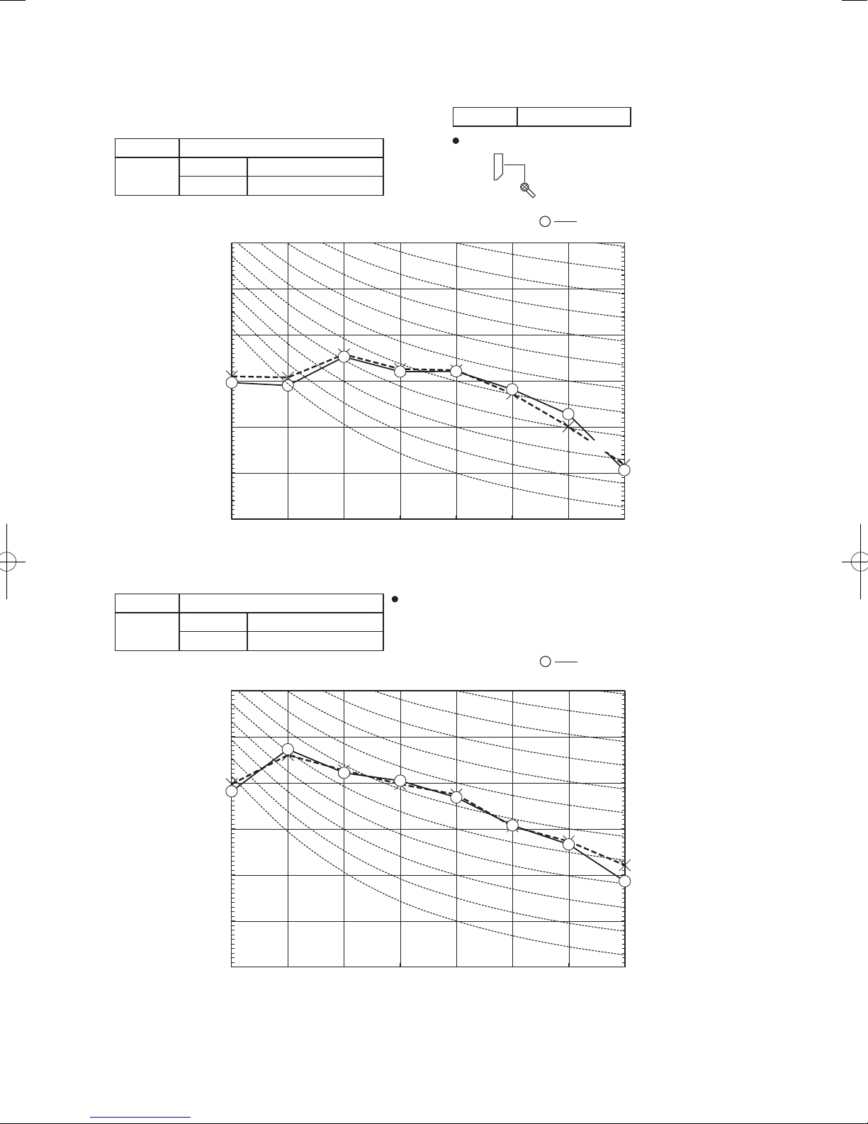
Model SRK35ZSX-S
Outdoor
Air flow
air temp.
10 3.94 3.46 4.13 3.40 4.28 3.57 4.35 3.53 4.43 3.49 4.56 3.64 4.68 3.55
12 3.87 3.42 4.06 3.37 4.22 3.55 4.29 3.51 4.37 3.47 4.51 3.62 4.63 3.53
14 3.80 3.39 3.99 3.34 4.16 3.52 4.24 3.49 4.31 3.45 4.46 3.61 4.59 3.52
16 3.72 3.36 3.91 3.31 4.09 3.50 4.18 3.46 4.25 3.43 4.40 3.59 4.54 3.50
18 3.65 3.32 3.84 3.28 4.03 3.47 4.11 3.44 4.19 3.40 4.35 3.57 4.49 3.49
20 3.57 3.28 3.76 3.24 3.96 3.44 4.05 3.41 4.13 3.38 4.29 3.55 4.43 3.47
22 3.49 3.24 3.68 3.20 3.89 3.42 3.98 3.39 4.06 3.36 4.23 3.53 4.38 3.46
24 3.40 3.20 3.59 3.17 3.81 3.39 3.91 3.36 3.99 3.33 4.17 3.51 4.32 3.44
Hi
13.1
26 3.32 3.15 3.51 3.13 3.74 3.35 3.84 3.34 3.92 3.31 4.11 3.49 4.26 3.42
3
/min)
(m
28 3.23 3.07 3.42 3.10 3.66 3.32 3.77 3.30 3.85 3.28 4.04 3.47 4.20 3.40
30 3.14 2.98 3.33 3.06 3.58 3.29 3.70 3.28 3.78 3.25 3.98 3.44 4.13 3.37
32 3.05 2.90 3.24 3.02 3.50 3.26 3.62 3.25 3.70 3.22 3.91 3.42 4.06 3.36
34 2.95 2.81 3.14 2.98 3.41 3.23 3.54 3.22 3.62 3.19 3.84 3.39 4.00 3.33
35 2.91 2.76 3.10 2.94 3.37 3.20 3.50 3.20 3.58 3.18 3.80 3.38 3.96 3.32
36 2.86 2.72 3.05 2.90 3.33 3.16 3.46 3.19 3.54 3.17 3.76 3.37 3.92 3.31
38 2.76 2.62 2.95 2.80 3.24 3.08 3.38 3.16 3.46 3.14 3.69 3.35 3.85 3.29
39 2.71 2.57 2.90 2.75 3.20 3.04 3.33 3.15 3.42 3.12 3.65 3.34 3.81 3.28
Cooling Mode
21˚CDB 23˚CDB 26˚CDB 27˚CDB 28˚CDB 31˚CDB 33˚CDB
14˚CWB 16˚CWB 18˚CWB 19˚CWB 20˚CWB 22˚CWB 24˚CWB
TC SHC TC SHC TC SHC TC SHC TC SHC TC SHC TC SHC
Indoor air temp
-
24
Heating Mode (HC) (kW)(kW)
outdoor
Air flow
air temp.
16˚CDB 18˚CDB 20˚CDB 22˚CDB 24˚CDB
-15˚CWB 2.65 2.59 2.53 2.48 2.42
-10˚CWB 2.99 2.94 2.90 2.83 2.77
-5˚CWB 3.24 3.20 3.13 3.10 3.05
0˚CWB 3.40 3.35 3.29 3.25 3.20
Hi
13.9
3/m
(m
Notes(1) These data show average statuses.
5˚CWB 4.33 4.28 4.26 4.17 4.11
in)
6˚CWB 4.40 4.35 4.30 4.25 4.19
10˚CWB 4.68 4.63 4.60 4.54 4.49
15˚CWB 5.09 5.04 5.01 4.95 4.91
20˚CWB 5.47 5.42 5.40 5.34 5.29
Depending on the system control, there may be ranges where the operation
is not conducted continuously.
These data show the case where the operation frequency of a compressor is
fixed.
(2) Capacities are based on the following conditions.
Corresponding refrigerant piping length :7m
Level difference of Zero.
(3) Symbols are as follows.
TC : Total cooling capacity (kW)
SHC : Sensible heat capacity (kW)
HC : Heating capacity (kW)
indoor air temp
-
'17 • SRK-T-203
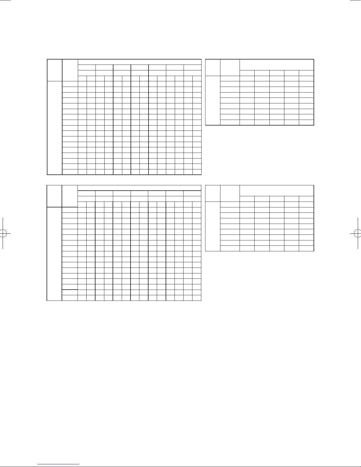
Model SRK50ZSX-S
21˚CDB 23˚CDB 26˚CDB 27˚CDB 28˚CDB 31˚CDB 33˚CDB
Outdoor
Air flow
air temp.
14˚CWB 16˚CWB 18˚CWB 19˚CWB 20˚CWB 22˚CWB 24˚CWB
TC SHC TC SHC TC SHC TC SHC TC SHC TC SHC TC SHC
10 5.63 4.45 5.90 4.37 6.11 4.54 6.22 4.48 6.32 4.42 6.51 4.57 6.69 4.43
12 5.53 4.40 5.80 4.32 6.03 4.50 6.14 4.45 6.25 4.39 6.44 4.54 6.62 4.40
14 5.43 4.34 5.70 4.28 5.94 4.47 6.05 4.42 6.16 4.36 6.37 4.51 6.55 4.38
16 5.32 4.29 5.59 4.23 5.85 4.43 5.96 4.38 6.08 4.33 6.29 4.48 6.48 4.36
18 5.21 4.24 5.48 4.18 5.75 4.39 5.88 4.34 5.99 4.29 6.21 4.45 6.41 4.33
20 5.10 4.18 5.37 4.13 5.65 4.35 5.78 4.31 5.90 4.26 6.13 4.42 6.33 4.31
22 4.98 4.13 5.25 4.08 5.55 4.30 5.69 4.26 5.80 4.21 6.05 4.39 6.25 4.28
24 4.86 4.07 5.14 4.02 5.45 4.25 5.59 4.22 5.71 4.18 5.96 4.36 6.17 4.25
Hi
14.3
26 4.74 4.01 5.01 3.97 5.34 4.21 5.49 4.18 5.61 4.14 5.87 4.33 6.08 4.23
3
/min)
(m
28 4.61 3.95 4.89 3.91 5.23 4.16 5.39 4.14 5.50 4.10 5.78 4.30 5.99 4.20
30 4.49 3.89 4.76 3.86 5.11 4.12 5.28 4.10 5.40 4.06 5.68 4.26 5.90 4.17
32 4.35 3.82 4.63 3.80 5.00 4.07 5.17 4.05 5.29 4.02 5.58 4.22 5.81 4.13
34 4.22 3.76 4.49 3.74 4.88 4.01 5.06 4.01 5.18 3.98 5.48 4.19 5.71 4.10
35 4.15 3.73 4.42 3.70 4.82 3.99 5.00 3.99 5.12 3.95 5.43 4.17 5.66 4.08
36 4.08 3.70 4.35 3.67 4.76 3.96 4.94 3.96 5.06 3.93 5.37 4.15 5.61 4.07
38 3.94 3.63 4.21 3.61 4.63 3.91 4.82 3.91 4.94 3.88 5.27 4.11 5.50 4.04
39 3.87 3.60 4.14 3.58 4.57 3.89 4.76 3.89 4.88 3.86 5.21 4.09 5.45 4.02
Model SRK60ZSX-S
21˚CDB 23˚CDB 26˚CDB 27˚CDB 28˚CDB 31˚CDB 33˚CDB
Outdoor
Air flow
air temp.
14˚CWB 16˚CWB 18˚CWB 19˚CWB 20˚CWB 22˚CWB 24˚CWB
TC SHC TC SHC TC SHC TC SHC TC SHC TC SHC TC SHC
10 6.87 5.29 7.19 5.21 7.46 5.38 7.58 5.30 7.72 5.23 7.94 5.38 8.16 5.21
12 6.75 5.23 7.07 5.14 7.35 5.33 7.48 5.26 7.62 5.19 7.86 5.35 8.08 5.18
14 6.62 5.17 6.95 5.08 7.24 5.28 7.38 5.22 7.52 5.15 7.77 5.31 8.00 5.15
16 6.49 5.10 6.82 5.02 7.13 5.23 7.28 5.18 7.42 5.11 7.68 5.27 7.91 5.12
18 6.36 5.03 6.69 4.96 7.02 5.18 7.17 5.13 7.31 5.06 7.58 5.24 7.82 5.09
20 6.22 4.96 6.55 4.89 6.89 5.13 7.06 5.08 7.20 5.02 7.48 5.20 7.73 5.06
22 6.08 4.89 6.41 4.83 6.77 5.07 6.94 5.01 7.08 4.96 7.38 5.16 7.63 5.03
24 5.93 4.81 6.27 4.76 6.64 5.00 6.82 4.97 6.96 4.91 7.27 5.13 7.53 4.99
Hi
16.3
26 5.78 4.74 6.12 4.69 6.51 4.95 6.70 4.92 6.84 4.86 7.16 5.08 7.42 4.95
3
/min)
(m
28 5.63 4.66 5.96 4.62 6.38 4.89 6.57 4.86 6.71 4.82 7.05 5.04 7.31 4.92
30 5.47 4.59 5.81 4.55 6.24 4.83 6.44 4.81 6.58 4.76 6.93 5.00 7.20 4.88
32 5.31 4.51 5.65 4.48 6.10 4.78 6.31 4.76 6.45 4.71 6.81 4.95 7.08 4.85
34 5.15 4.43 5.48 4.40 5.95 4.72 6.17 4.71 6.31 4.66 6.68 4.91 6.96 4.81
35 5.07 4.39 5.40 4.36 5.88 4.69 6.10 4.68 6.24 4.63 6.62 4.89 6.90 4.78
36 4.98 4.35 5.31 4.32 5.80 4.65 6.03 4.65 6.17 4.61 6.56 4.86 6.84 4.76
38 4.81 4.27 5.14 4.25 5.65 4.59 5.89 4.59 6.03 4.55 6.42 4.81 6.71 4.72
39 4.72 4.23 5.05 4.21 5.57 4.56 5.81 4.57 5.95 4.53 6.36 4.79 6.65 4.70
Cooling Mode
Indoor air temp
Cooling Mode
Indoor air temp
Heating Mode (HC) (kW)(kW)
outdoor
Air flow
air temp.
16˚CDB 18˚CDB 20˚CDB 22˚CDB 24˚CDB
-15˚CWB 3.69 3.61 3.53 3.45 3.38
-10˚CWB 4.18 4.10 4.05 3.95 3.86
-5˚CWB 4.52 4.46 4.37 4.32 4.25
0˚CWB 4.74 4.67 4.59 4.54 4.47
Hi
17.3
(m
Air flow
17.8
(m
Notes(1) These data show average statuses.
5˚CWB 6.04 5.97 5.94 5.82 5.74
3
/min)
6˚CWB 6.14 6.07 6.00 5.92 5.85
10˚CWB 6.52 6.46 6.42 6.34 6.27
15˚CWB 7.10 7.04 6.99 6.91 6.85
20˚CWB 7.63 7.57 7.53 7.45 7.39
Heating Mode (HC) (kW)(kW)
outdoor
air temp.
16˚CDB 18˚CDB 20˚CDB 22˚CDB 24˚CDB
-15˚CWB 4.18 4.09 4.00 3.92 3.83
-10˚CWB 4.73 4.65 4.59 4.47 4.38
-5˚CWB 5.13 5.05 4.95 4.90 4.82
0˚CWB 5.38 5.30 5.20 5.14 5.07
Hi
5˚CWB 6.85 6.77 6.73 6.60 6.51
3
/min)
6˚CWB 6.96 6.88 6.80 6.71 6.63
10˚CWB 7.39 7.32 7.28 7.18 7.11
15˚CWB 8.05 7.98 7.92 7.83 7.76
20˚CWB 8.65 8.58 8.54 8.44 8.37
Depending on the system control, there may be ranges where the operation
is not conducted continuously.
These data show the case where the operation frequency of a compressor is
fixed.
(2) Capacities are based on the following conditions.
Corresponding refrigerant piping length :7m
Level difference of Zero.
(3) Symbols are as follows.
TC : Total cooling capacity (kW)
SHC : Sensible heat capacity (kW)
HC : Heating capacity (kW)
indoor air temp
indoor air temp
-
25
-
'17 • SRK-T-203
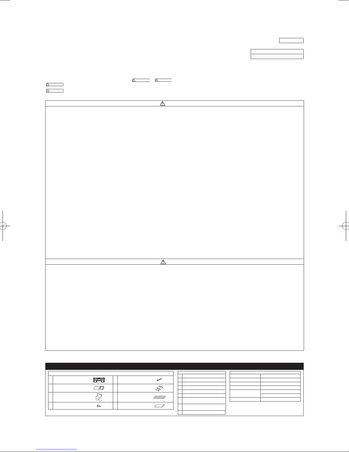
WARNING
CAUTION
WARNING
CAUTION
8. APPLICATION DATA
(1) Installation of indoor unit
•
This installation manual deals with an indoor unit installation only. For an outdoor unit installation, refer to page 30.
• Before installation, read the “SAFETY PRECAUTIONS” carefully and strictly follow it during the installation work in order to protect yourself.
•
The precautionary items mentioned below are distinguished into two levels,
Indicates a potentially hazardous situation which, if not avoided, can result in serious con-
sequences such as death or severe injury.
Indicates a potentially hazardous situation which, if not avoided, can result in personal inju-
Both mention the important items to protect your health and safety. Therefore, strictly follow them by any means.
• Be sure to use only for residential purpose.
If this unit is installed in inferior environment such as machine shop, vehicle (like ship), warehouse,
• Installationmustbe carriedoutbythequalied installercompletelyinaccor-
Installationbynon qualiedpersonorincorrect installationcancauseserious troublessuchaswater
•
Impropersafetymeasurescanresultinpersonalinjury.
• Usetheoriginalaccessoriesandthespeciedcomponentsfortheinstallation.
Usingpartsotherthanthoseprescribedmaycausewaterleak,electricshock,reandpersonalinjury.
•
Ifleaked gasesaccumulate around theunit, itcan causere resultingin propertydamage andper-
• When installing the unit in small rooms, make sure that refrigerant density
If refrigerant density exceeds the limit, consult the dealer and install the ventilation system.
Otherwise lack of oxygen can occur resulting in serious accident.
• Install the unit in a location where unit will remain stable, horizontal and free
Unsuitableinstallationlocationcancausetheunittofallresultinginmaterialdamageandpersonalinjury.
• Do not run the unit with removed panels or protections.
Touchingrotatingequipments, hot surfacesor highvoltage parts cancause personal injurydue to
• ThisunitisdesignedspecicallyforR410A.
Usinganyotherrefrigerantcancauseunitfailureandpersonalinjury.
• DonotventR410Aintoatmosphere.
R410AisauorinatedgreenhousegaswithaGlobalWarmingPotential(GWP)=2088.
• Make sure that no air enters the refrigerant circuit when the unit is installed
If air enters the refrigerant circuit, the pressure in the refrigerant circuit will become too high, which
• Besuretousetheprescribedpipes,arenutsandtoolsforR410A.
Usingexistingparts(forR22orR407C)can causerefrigerantcircuitburstresultinginunit failureand
• Be sure to connect both liquid and gas connecting pipes properly before op-
Do not open the liquid and gas service valves before completing piping work,
If the compressor is operated when connecting pipes are not connected and service valves are open,
• Besuretotightenthearenutstospeciedtorqueusingthetorquewrench.
Tighteningarenutswithexcesstorquecancauseburstandrefrigerantleakageafteralongperiod.
• Take care when carrying the unit by hand.
Iftheunitweightismorethan20kg,itmustbecarriedbytwoormorepersons.
Do not carry the unit by the plastic straps. Always use the carry handle.
• Do not install the outdoor unit in a location where insects and small animals
Insectsandsmallanimalscanentertheelectricalpartsandcause damageresultinginreorperson
• If the outdoor unit is installed at height, make sure that there is enough space
Insufcientspacecanresultinpersonalinjuryduetofallingfromtheheight.
• Do not install the unit near the location where neighbours are bothered by
It can affect surrounding environment and cause a claim.
• Do not install in the locations where unit is directly exposed to corrosive
It can cause corrosion of heat exchanger and damage to plastic parts.
• Do not install the unit close to the equipments that generate electromagnetic
Equipment such as inverters, standby generators, medical high frequency equipments and telecom-
The system can also affect medical equipment and telecommunication equipment, and obstruct its
ry or property damage.
etc., it can malfunction.
dance with the installation manual.
leak,electricshock,reandpersonalinjury.
Be sure to wear protective goggles and gloves while performing installation work.
Donotinstalltheunitnearthelocationwhereleakageofammablegasescanoccur.
sonalinjury.
does not exceed the limit (Reference: ISO5149) in the event of leakage.
of any vibration transmission.
entrapment, burn or electric shock.
and removed.
cancauseburstandpersonalinjury.
personalinjury.
erating the compressor.
and evacuation.
air can be sucked into the refrigerant circuit which can cause anomalous high pressure resulting in
burstorpersonalinjury.
can inhabit.
alinjury.Instructtheusertokeepthesurroundingsclean.
for installation, maintenance and service.
noise or air generating from the unit.
gases (like sulphide gas, chloride gas), sea breeze or salty atmosphere.
waves and/or high-harmonic waves.
munication equipments can affect the system, and cause malfunctions and breakdowns.
functionorcausejamming.
SAFETY PRECAUTIONS
and
•Be sureto conrmno operation problemon theequipment after completingthe installation. Ifunusual
noise can be heard during the test run, consult the dealer.
• Be sure to explain the operating methods as well as the maintenance methods of this equipment to the
.
user according to the user’s manual.
• Be sure to keep the installation manual together with user’s manual at a place where it is easily accessible to the user any time. Moreover, ask the user to hand the manuals to a new user, whenever required.
WARNING
• During pump down work, be sure to stop the compressor before closing ser
vice valves and removing connecting pipes.
If the connecting pipes are removed when the compressor is in operation and service valves are
open, air can be sucked into the refrigerant circuit which can cause anomalous high pressure result
inginburstorpersonalinjury.
• In the event of refrigerant leakage during installation, be sure to ventilate the
working area properly.
Iftherefrigerantcomesintocontactwithnakedames,poisonousgaseswillbeproduced.
• Electricalwork mustbe carriedoutbythequalied electrician,strictlyinac-
cordance with national or regional electricity regulations.
Incorrectinstallationcancauseelectricshock,reorpersonalinjury.
• Make sure that earth leakage breaker and circuit breaker of appropriate ca
pacities are installed.
Circuitbreaker should beable to disconnectall poles underover current.Absence ofappropriate
breakerscancauseelectricshock,personalinjuryorpropertydamage.
• Be sure to switch off the power source in the event of installation, mainte
nance or service.
Ifthepowersourceisnotswitchedoff,thereisariskofelectricshock,unitfailureorpersonalinjury.
• Be sure to tighten the cables securely in terminal block and relieve the ca-
bles properly to prevent overloading the terminal blocks.
Looseconnectionsorcablemountingscancauseanomalousheatproductionorre.
• Do not process, splice or modify the power cable, or share the socket with
other power plugs.
Improperpower cableorpower plugcancause reor electricshockdue topoorconnection, insuf
cient insulation or over-current.
• Do not perform any change in protective device or its setup condition yourself.
Changingprotectivedevicespecicationscancauseelectricshock,reorburst.
• Be sure to clamp the cables properly so that they do not touch any internal
component of the unit.
Ifcablestouchanyinternalcomponent,itcancauseoverheatingandre.
• Be sure to install service cover properly.
Improperinstallationcancauseelectricshockorreduetointrusionofdustorwater.
• Be sure to use the prescribed power and connecting cables for electrical work.
Usingimpropercablescancauseelectricleak,anomalousheatproductionorre.
• This appliance must be connected to main power source by means of a cir
cuit breaker or switch with a contact separation of at least 3mm.
Improperelectricalworkcancauseunitfailureorpersonalinjury.
•
Whenpluggingthisunit,aplugconformingtothenormIEC60884-1mustbeused.
Usingimproperplugcancauseelectricshockorre.
• Be sure to connect the power source cable with power source properly.
Improperconnectioncancauseintrusionofdustorwaterresultinginelectricshockorre.
CAUTION
• Do not install the unit in the locations where:
• There are heat sources nearby.
• Unit is directly exposed to rain or sunlight.
• There is any obstacle which can prevent smooth air circulation from inlet and outlet side of the unit.
• Unit is directly exposed to oil mist and steam such as kitchen.
•Chemical substances likeammonia (organic fertilizer),calcium chloride (snowmelting agent) and
acid (sulfurous acid etc.), which can harm the unit, will generate or accumulate.
• Drain water can not be discharged properly.
• TV set or radio receiver is placed within 1m.
• Height above sea level is more than 1000m.
Itcancauseperformancedegradation,corrosionanddamageofcomponents,unitmalfunctionandre.
• Dispose of all packing materials properly.
Packingmaterialscontainnailsandwoodwhichcancausepersonalinjury.
Keep the polybag away from children to avoid the risk of suffocation.
• Do not put anything on the outdoor unit.
Objectmayfallcausingpropertydamageorpersonalinjury.
• Donottouchthealuminumnoftheoutdoorunit.
Aluminiumntemperatureishighduringheatingoperation.Touchingncancauseburn.
•
Do not touch any refrigerant pipe with your hands when the system is in operation.
During operation the refrigerant pipes become extremely hot or extremely cold depending on the
operatingcondition.Touchingpipescancausepersonalinjurylikeburn(hot/cold).
• Install isolator or disconnect switch on the power source wiring in accor
dance with the local codes and regulations.
TheisolatorshouldbelockedinOFFstateinaccordancewithEN60204-1.
RLF012A200
ModelSRK20,25,35,50,60ZSX-S
R410AREFRIGERANTUSED
-
-
-
-
-
-
-
1. ACCESSORIES AND TOOLS
Standard accessories (supplied with indoor unit)
(1) Installation board
(2) Wireless remote control
(3) Remote control holder
Tapping screws
(4)
(for installation board ø4 X 25mm)
1pc (5)
1pc (6)
1pc (7) Air-cleaninglters 2pcs
4pcs (8) Insulation (#486 50 X 100 t3) 1pc
Wood screws
(for remote control holder ø3.5 X 16mm)
Batteries [R03 (AAA, Micro) 1.5V]
(a) Sleeve (1pc)
2pcs
(b) Sealing plate (1pc)
(c) Inclination plate (1pc)
(d) Putty
2pcs
(e) Connecting cable
(f) Drain hose (extension hose)
Piping cover
(g)
(for insulation of connection piping)
Clampandscrew(fornishing
(h)
work)
(i) Electrical tape
-
-
26
Locally procured parts
Plus headed driver Pipe cutter
Knife
Saw Wrench key (Hexagon) [4m/m]
Tape measure Flaring tool set*
Torque wrench
(14.0-62.0N·m (1.4-6.2kgf·m))
Plier Flare adjustment gauge
Tools for installation Work
Hole core drill (65mm in diameter)
Gas leak detector*
Pipe bender
*DesignedspecicallyforR410A
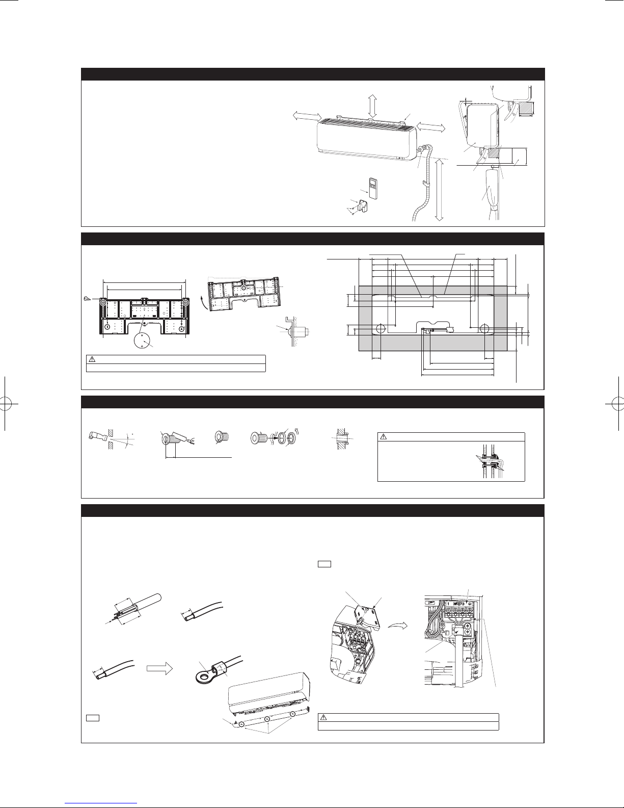
'17 • SRK-T-203
2.SELECTINGINSTALLATIONLOCATION
6.5 cm minimum from the ceiling
hole
630
Mating mark for level surface
277.317.4
Installation board
Unit
Indoor side Outdoor side
Indoor side Outdoor side Installed state
(c) Inclination plate
(d) Putty
(d) Putty
Earth wir
10mm
10mm
Round crimp-type terminal
The screw of the terminal
cover is tightened securely
Bottom panel
Screw (in the cap)
After getting customer’s approval, select installation location according to following guidelines.
1. Indoor unit
• Wherethereisnoobstructiontotheairowandwherethecooledandheatedaircanbe
evenly distributed.
• A solid place where the unit or the wall will not vibrate.
• A place where there will be enough space for servicing.
(Where space mentioned on the right side can be secured.)
• Where it is easy to conduct wiring and piping work.
• A place where unit is not directly exposed to sunlight or street light.
• A place where it can be easily drained.
• A place separated at least 1m away from the television or the radio.
(To prevent interference to images and sounds.)
• A place where this unit is not affected by the high frequency equipment or electric equipment.
• Avoid installing this unit in place where there is much oil mist.
• A place where there is no electric equipment or household.
• Installtheindoorunitonthewallwheretheheightfromtheoortothebottomoftheunitis
more than 180 cm.
2.Wirelessremotecontrol
• A place where the air-conditioner can receive the signal surely during operating the wireless
remote control.
• A place where it is not affected by the TV and radio etc.
• Do not place where it is exposed to direct sunlight or near heat devices such as a stove.
3. INSTALLING INSTALLATION BOARD
• Installation board should be installed on the wall which can support the weight of the indoor unit.
• Adjustment of the installation board in the horizontal direction is to be conducted with 4 screws in a
temporary tightened state.
• With the standard hole as a center, adjust the board and level it.
Bolt
(M6X12)
Standard
568
In case of fixing the unit on
concrete wall, use nut anchor.
CAUTION
Improper adjustment of the installation board can cause water leakage.
10 cm minimum
from the wall
Remote control holder
Wireless
remote control
Wood screws
(Service Space)
88.6
76.6
100
48.6
47
65
(In the case of less than 10 cm,
there is a possibility of performance
degradation.)
145 630
(a) Sleeve
460
Installation board
10 cm minimum
from the wall
568176
Installation example
2 cm
Indoor
unit
Be sure that the
flap of outlet
should not
touch any
obstacles.
Obstacle such
as curtain
180 cm minimum from the floor
100
118.5118.5 683
176
145
460
480 (Gas pipe)
533 (Drain hose)
548 (Liquid pipe)
70
Unit: mm
Maximum
moving range
11 cm 12 cm
Flap removal
position
Need to
secure a
space for
service
(Service Space)
65
47
120
7.9 cm
56.4
7.0
cm
10.3
4.DRILLINGHOLEANDFIXTUREOFSLEEVE
When drilling the wall that contains a metal lath, wire lath or metal plate, be sure to use sealing plate, sleeve and inclination plate (Locally procured parts).
5
ø65
(1) Drill a hole with hole
core drill.
(a) Sleeve
Top
Thickness of the wall + 1.5cm
(2) Cut sleeve to adjust to wall
thickness. In case of rear
piping draw out, cut off the
lower and the right side
portions of the sleeve collar.
Cut
(a) Sleeve
(3) Fix sealing plate, sleeve
and inclination plate.
(b) Sealing plate
Turn to
tighten
CAUTION
After passing the wirings and pipes
through the hole, completely seal
the hole on the wall with putty to
prevent water leakage.
5. ELECTRICAL WIRING WORK
• Beforeinstallation,makesurethatthepowersourcecomplieswiththeair-conditioner ’spowerspecication.
• Carry out electrical wiring work according to following guidelines.
1. Preparing cable
(1) Selecting cable
Selecttheconnectingcableinaccordancewiththespecicationsmentionedbelow.
4-core* 1.5mm
* 1 Earth wire is included (Yellow/Green).
(2) Arrange each wire length as shown below.
Make sure that each wire is stripped 10mm from the end.
2
conformed with 60245 IEC57 (CENELEC H05RN-F)
<Connecting cable> <Wire end>
30mm or more
40mm or more
e
(3) Attach round crimp-type terminal to each wire as shown in the below.
Selectthesizeofroundcrimp-typeterminalafterconsideringthespecicationsofterminalblock
and wire diameter.
2.Removebottompanel
(1) Remove the 3 screws (in the cap).
(2) Remove the hooks of left and right side
and then bottom panel can be removed.
NOTE
• Openthecapusingane-tippedtool.
• When opening the cap, exercise care not to
damage the design surface.
Sleeve
3. Connecting cable
(1) Remove the terminal cover.
(2) Remove the cable clamp.
(3) Connect the connecting wires to the terminal block.
(4) Fix the connecting cable by cable clamp.
(5) Fix the terminal cover.
NOTE
Take care not to confuse the terminal numbers for indoor and outdoor connections.
.
Terminal cover
Cable clamp
CAUTION
Incorrectwiringconnectioncancausemalfunctionorre.
Terminal block
• Earth wire shall be Yellow/Green (Y/G) in color and
longer than other wires for safety reason.
-
27
-
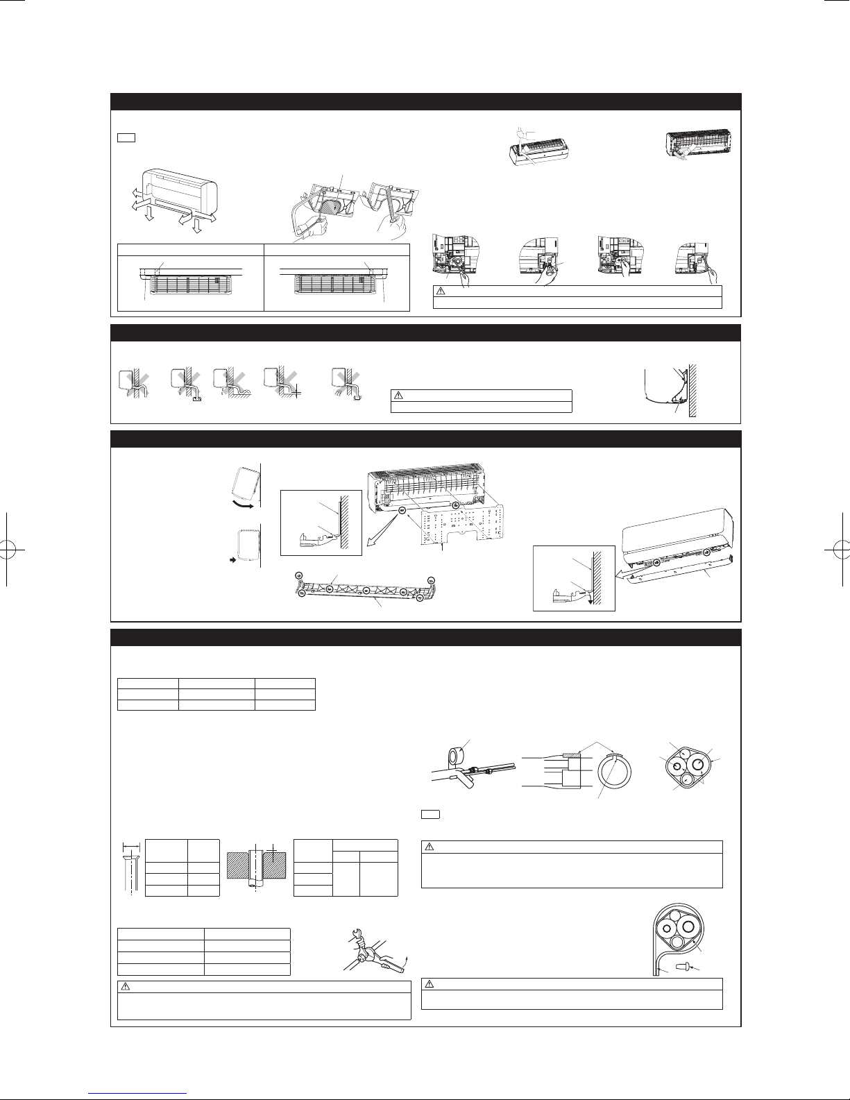
'17 • SRK-T-203
6. FORMING PIPING AND DRAIN HOSE
Cut out the panel smoothly along the
Right
Left downward
Left
Piping in the left direction
Piping in the left rear direction
Piping in the right rear direction
Piping in the right direction
(1)(2) (3)(4)
Higher than
specifie
Gutter
Pipe space
Indoor unit
Bottom panel
A
B
(Do not turn)
Liquid side
Tape
Insulation pad
Position it so that the slit area faces upward.
Connecting cable
Liquid pip
Drain hose
Gas pipe
Clamp
1. Forming piping
Piping is possible in the right, rear, downward, left, left rear or left downward direction.
NOTE
Sufcientcaremustbetakennottodamage
the panels when connecting pipes.
line in case of side or bottom piping.
Rear
Left
Downward
rear
Forming of pipings
• Hold the bottom of the
pipingandxdirection
before stretching it
and shaping it.
2.Drainchangeprocedures
(1) Remove the screw and drain hose.
(2) Remove the drain cap by hand or pliers.
(3) Insert the drain cap which was removed at procedure (2) securely using a hexagonal wrench etc.
(4) Install the drain hose and screw securely.
Pipings
Taping of the exterior
• Tape only the portion that
goes through the wall.
• Always tape the wiring
with the piping.
Left hand side piping Right hand side piping
7. DRAINAGE WORK
• Arrange the drain hose in a downward angle.
• Avoid the following drain piping.
The drain hose
tip is in water.
d
Wavy
8.INSTALLINGINDOORUNIT
1. Installing the indoor unit to installation board 2.Removingtheindoorunitfrominstallationboard
(1) Pass the pipe through the hole
in the wall, and hook the upper
part of the indoor unit to the
installation board.
(2)
Gently push the lower part to
fix the indoor unit base lower
latch to installation board.
(3) Install the latches of the bottom panel
(7 locations).
Secure the bottom panel with the 3 screws
(in the cap).
9. CONNECTING PIPING WORK
1. Preparation of connecting pipe
1.1. Selecting connecting pipe
Select connecting pipe according to the following table.
Gas pipe ø9.52 ø12.7
Liquid pipe ø6.35 ø6.35
• Pipe wall thickness must be greater than or equal to 0.8 mm.
• Pipe material must be O-type (Phosphorus deoxidized seamless copper pipe ICS 23.040.15, ICS
77.150.30).
1.2.Cuttingconnectingpipe
(1) Cut the connecting pipe to the required length with pipe cutter.
(2)
Hold the pipe downward and remove the burrs. Make sure that no foreign material enters the pipe.
(3) Cover the connecting pipe ends with the tape.
2.Pipingwork
2.1.Flaringpipe
(1)
Takeoutarenutsfromtheservicevalvesofindoorunitandengagethemontoconnectingpipes.
(2) Flarethepipesaccordingtotableandgureshownbelow.
Flare dimensions for R410A are different from those for conventional refrigerant.
Although itis recommendedto use thearing toolsdesigned specically forR410A, conventional
aringtools canalso be usedby adjustingthe measurement ofprotrusion Bwith a areadjustment
gauge.
2.2Connectingpipes
(1) Connect pipes on both liquid and gas sides.
(2)Tightennutstospeciedtorqueshowninthetablebelow.
Operation valve size (mm) Tightening torque (N·m)
ø6.35 (1/4") 14-18
ø9.52 (3/8") 34-42
ø12.7 (1/2") 49-61
CAUTION
• Donotapplyrefrigeratingmachineoiltothearedsurface.Itcancauserefrigerantleakage.
• Donotapplyexcesstorquetothearednuts.Thearednutsmaycrackresultinginrefrigerant
leakage.
Model SRK20/25/35 Model SRK50/60
Copperpipe
A
outer diameter
0
–0.4
ø6.35 9.1 ø6.35
ø12.7 16.6 ø12.7
The gap to the ground
is 5 cm or less.
Installation board
Indoor unit base latch
(2 locations)
outer diameter
Odor from
the gutter
Copperpipe
The drain hose tip
is in the gutter.
Wall
Latch (7 locations)
Rigid (clutch) type
R410A Conventional
0 - 0.5 1.0 - 1.5ø9.52 13.2 ø9.52
Gas side
Drain cap
Screw
CAUTION
Incorrect installation of drain hose and cap can cause water leakage.
• Pour water to the drain pan located under the heat exchanger, and ensure that the water is discharged outdoor.
• When extended drain hose is present inside the room, insulate it securely with heat insulator available in the market.
Since this air-conditioner is designed to collect dew drops on the rear surface to the
drain pan, do not install the connecting wire above the gutter.
CAUTION
Incorrect drainage work can cause water leakage.
(1) Remove the bottom panel. (Refer to 5.2)
(2) Pull the indoor unit base latch downward. (both right and left
hand sides). (The indoor unit base latch can be removed from the
installation board.)
(3) Push up the indoor unit upward so that it can be removed from
installation board.
Installation board
3. Heating and condensation prevention
(1) Dress the connecting pipes (both liquid and gas pipes) with insulation to prevent it from heating and
dew condensation.
Use the heat insulating material which can withstand 120°C or higher temperature. Make sure that insu
lation is wrapped tightly around the pipes and no gap is left between them.
(2) Wrap the refrigerant pipings of indoor unit with indoor unit heat insulation using tape.
(3) Coverthe are-connectedjoints (indoorside) with theindoor unitheat insulation andwrap itwith an
insulation pad (standard accessory provided with indoor unit).
(4) Wrap the connecting pipes, connecting cable and drain hose with the tape.
(2) (3) (4)
NOTE
Locations where relative humidity exceeds 70%, both liquid and gas pipes need to be dressed with 20mm
thicker heat insulation materials.
CAUTION
• Improper insulation can cause condensate(water) formation during cooling operation.
Condensate can leak or drip causing damage to household property.
• Poor heat insulating capacity can cause pipe outer surface to reach high temperature during heating
operation. It can cause cable deterioration and personal injury.
4. Finishing work
(1) Make sure that the exterior portion of connecting pipes, connecting cable
and drain hose is wrapped properly with tape. Shape the connecting pipes
to match with the contours of the pipe assembly route.
(2) Fix the pipe assembly with the wall using clamps and screws. Pipe assem-
bly should be anchored every 1.5m or less to isolate the vibration.
(3) Install the service cover securely. Water may enter the unit if service cover
is not installed properly, resulting in unit malfunction and failure.
CAUTION
Make sure that the connecting pipes do not touch the components within the unit. If pipes touch the
internal components, it may generate abnormal sounds and/or vibrations.
-
-
28
Installation board
Indoor unit base latch
(2 locations)
Wall
Wall
Bottom panel
e
Insulation
Pipe
assembly
Screw
Tape
-
or
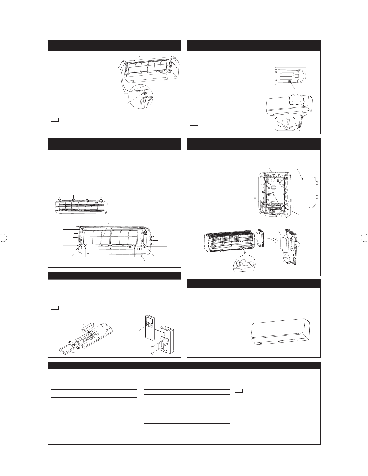
'17 • SRK-T-203
Air inlet panel
Panel ar
Cut
<Top view>
Scre
CNS terminal
<Right side>
Front panel
Bottom panel
)
Screw
Side panel (L)
Interface kit
Latch
cable through here.
Unit ON/OFF button
Wirekess
remote contro
Cover
Battery
10.HOWTOOPEN,CLOSE,REMOVEANDINSTALL
THE AIR INLET PANEL
1. Open
Pull the air inlet panel at both ends of lower part
and release latches, then pull up the panel until
you feel resistance.
(The panel stops at approx. 60° open position)
2.Close
Hold the panel at both ends of lower part, lower
it downward slowly, then push it slightly until the
latch works.
3. Removing
Open the panel by 80 degrees (as shown in the
right illustration) and then pull it forward.
4. Installing
Insert the panel arm into the slot on the front
panel from the position shown in right illustration,
hold the panel at both ends of lower part, lower
it downward slowly, then push it slightly until the
latch works.
NOTE
• When carrying out maintenance, handle the air
inlet panel with care.
m
Approx. 80°
11.HOWTOREMOVEANDINSTALLTHESIDEAND
FRONT PANEL
1. Side panel (R/L)
1.1. Removing
(1) Remove the 2 screws.
(2) Remove the 3 latches and then side panel
can be removed.
1.2.Installing
(1)Covertheunitwiththesidepanelandx
3 latches.
(2) Secure the side panel with the 2 screws.
Latch
2.Frontpanel
2.1.Removing
(1) Remove the side panel (R/L), the air inlet
panel,theairltersandthebottompanel.
(2) Remove the 3 screws.
(3) Remove the 4 upper latches and then front
panel can be removed.
2.2.Installing
(1)Covertheunitwiththefrontpanelandx4
upper latches.
(2) Secure the front panel with the 3 screws.
(3) Install the bottom panel, the side panel
(R/L),theairinletpanelandtheairlters.
Screw
Side panel (R
13.
INSTALLING TWO AIR-CONDITIONERS IN THE SAME ROOM
In case two air-conditioners are installed in the same room, apply this setting so that one unit can be
operated with only one wirelesss remote control.
Setting one wirelesss remote control
(1) Slide and take out the cover and batteries.
(2) Cut the switching line next to the battery with
wire cutters.
(3) Set the batteries and cover again.
Setting one indoor unit
(1) Turn off the power source and turn it on after
1 minute.
(2) Send the signal by pressing the ACL switch
on the wireless remote control that was set
according to the procedure described on the
above side.
(3) Check that the reception buzzer sound “peep”
is emitted from the indoor unit. Since the signal
is sent about 6 seconds after the ACL switch is
pressed, point the wireless remote control to the
indoor unit for a while.
NOTE
If no reception buzzer is emitted, restart the setting
from the beginning.
TIME SETUP ACL
Reception
Peep
14. TERMINAL CONNECTION FOR AN INTERFACE
To install wired remote control, superlink etc., interface kit is needed.
Remove the air inlet panel, bottom panel
(1)
and side panel (R).
(2) Remove the control cover. (Remove
the screw.)
(3) There is a terminal (respectively marked
with CNS) for the indoor control board.
While connecting an interface, connect
to the respective terminal securely with
the connection harness supplied with
an option “Interface kit SC-BIKN-E” and
fasten the connection harness onto the
indoor control box with the clamp and
screw supplied with the kit.
(4)
Hooktoxtheinterfacekittothe2
latches on side panel (L).
For more details, refer to the user’s
manual of “Interface kit SC-BIKN-E”.
w
Indoor PCB
Control cover
Fixing point of
the clamp
Latches
Side panel (L)
Screw (Front panel)
Latches
Side panel (R)
Pass the interface kit
12.INSTALLINGWIRELESSREMOTECONTROL
Mount the batteries
(1) Slide and take out the cover of backside.
(2) Mount the batteries [R03 (AAA, Micro),
×2 pieces] in the body properly.
(Fithepoleswiththeindicationmarks+&−)
(3) Set the cover again.
NOTE
• Do not use new and old batteries together.
• In case the unit is not operated for a long time,
take out the batteries
Installing remote control holder
(1) Select the place where the unit can receive
signals.
(2) Fix the holder to pillar or wall with wood
screws.
l
Wood screws
ø3.5 X 16
15. PUMP DOWN WORK
For the environmental protection, be sure to pump down when relocating or disposing of the unit.
Pump down is the method of recovering refrigerant from the indoor unit to the outdoor unit before
the connecting pipes are removed from the unit. When pump down is carried out, forced cooling
operation is needed.
Forced cooling operation
(1) Turn off the power source and turn it on
again after 1 minute. The air inlet panel
andapopenandclose.
(2) After the air inlet panel closes, press the
ON/OFF button continuously for at least 5
seconds. Then operation will start.
For the detail of pump down, refer to the
installation manual of outdoor unit.
16. INSTALLATION CHECK AND TEST RUN
Afternishingtheinstallationwork,checkthefollowingpointsagainbeforeturningonthepower.Conductatestrunandensurethattheunitoperatesproperly.
At the same time, explain to the customer how to use the unit and how to take care of the unit following the user’s manual.
Before test run
Before test run, check following points.
Power source voltage complies with the rated voltage
of air-conditioner.
Earth leakage breaker and circuit breaker are installed.
Powercableandconnectingcablearesecurelyxedto
the terminal block.
Both liquid and gas service valves are fully open.
No gas leaks from the joints of the service valves.
Indoor and outdoor side pipe joints have been insulated.
Hole on the wall is completely sealed with putty.
Drain hose and cap are installed properly.
Screw of the terminal cover is tightened securely.
Test run
Check following points during test run.
Indoor unit receives signal of wireless remote control.
Air-conditioning operation is normal.
There is no abnormal noise.
Water drains out smoothly.
Display of wireless remote control is normal.
After test run
Explain the operating and maintenance methods to the
user according to the user’s manual.
Keep this installation manual together with user’s
manual.
-
-
29
NOTE
During restart or change in operation mode, the unit will not start
operating for approximately 3 minutes. This is to protect the unit
and it is not malfunction.
Side panel (L)

'17 • SRK-T-203
WARNING
CAUTION
WARNING
CAUTION
(2) Installation of outdoor unit
• This installation manual deals with an outdoor unit installation only. For an indoor unit installation, refer to page 26.
SAFETY PRECAUTIONS
• Before installation, read the “SAFETY PRECAUTIONS” carefully and strictly follow it during the installation work in order to protect yourself.
• The precautionary items mentioned below are distinguished into two levels,
Both mention the important items to protect your health and safety. Therefore, strictly follow them by any means.
Indicates a potentially hazardous situation which, if not avoided, can result in serious con-
sequences such as death or severe injury.
Indicates a potentially hazardous situation which, if not avoided, can result in personal
injury or property damage.
and
•Be sureto conrmno operation problemon theequipment after completingthe installation. Ifunusual
noise can be heard during the test run, consult the dealer.
• Be sure to explain the operating methods as well as the maintenance methods of this equipment to the
.
user according to the user’s manual.
• Be sure to keep the installation manual together with user’s manual at a place where it is easily accessible to the user any time. Moreover, ask the user to hand the manuals to a new user, whenever required.
WARNING
• Be sure to use only for residential purpose.
If this unit is installed in inferior environment such as machine shop, vehicle (like ship), warehouse,
etc., it can malfunction.
• Installationmustbe carriedoutbythequalied installercompletelyinaccor
dance with the installation manual.
Installationbynon qualiedpersonorincorrect installationcancauseserious troublessuchaswater
leak,electricshock,reandpersonalinjury.
Be sure to wear protective goggles and gloves while performing installation work.
•
Impropersafetymeasurescanresultinpersonalinjury.
• Usetheoriginalaccessoriesandthespeciedcomponentsfortheinstallation.
Usingpartsotherthanthoseprescribedmaycausewaterleak,electricshock,reandpersonalinjury.
Donotinstalltheunitnearthelocationwhereleakageofammablegasescanoccur.
•
Ifleaked gasesaccumulate around theunit, itcan causere resultingin propertydamage andper-
sonalinjury.
• When installing the unit in small rooms, make sure that refrigerant density
does not exceed the limit (Reference: ISO5149) in the event of leakage.
If refrigerant density exceeds the limit, consult the dealer and install the ventilation system.
Otherwise lack of oxygen can occur resulting in serious accident.
• Install the unit in a location where unit will remain stable, horizontal and free
of any vibration transmission.
Unsuitableinstallationlocationcancausetheunittofallresultinginmaterialdamageandpersonalinjury.
• Do not run the unit with removed panels or protections.
Touchingrotatingequipments, hot surfacesor highvoltage parts cancause personal injurydue to
entrapment, burn or electric shock.
• ThisunitisdesignedspecicallyforR410A.
Usinganyotherrefrigerantcancauseunitfailureandpersonalinjury.
• DonotventR410Aintoatmosphere.
R410AisauorinatedgreenhousegaswithaGlobalWarmingPotential(GWP)=2088.
• Make sure that no air enters the refrigerant circuit when the unit is installed
and removed.
If air enters the refrigerant circuit, the pressure in the refrigerant circuit will become too high, which
cancauseburstandpersonalinjury.
• Besuretousetheprescribedpipes,arenutsandtoolsforR410A.
Usingexistingparts(forR22orR407C)can causerefrigerantcircuitburstresultinginunit failureand
personalinjury.
• Be sure to connect both liquid and gas connecting pipes properly before operating the compressor.
Do not open the liquid and gas service valves before completing piping work,
and evacuation.
If the compressor is operated when connecting pipes are not connected and service valves are open,
air can be sucked into the refrigerant circuit which can cause anomalous high pressure resulting in
burstorpersonalinjury.
• Besuretotightenthearenutstospeciedtorqueusingthetorquewrench.
Tighteningarenutswithexcesstorquecancauseburstandrefrigerantleakageafteralongperiod.
• During pump down work, be sure to stop the compressor before closing service valves and removing connecting pipes.
If the connecting pipes are removed when the compressor is in operation and service valves are
-
open, air can be sucked into the refrigerant circuit which can cause anomalous high pressure result
inginburstorpersonalinjury.
• In the event of refrigerant leakage during installation, be sure to ventilate the
working area properly.
Iftherefrigerantcomesintocontactwithnakedames,poisonousgaseswillbeproduced.
• Electricalwork mustbe carriedoutbythequalied electrician,strictlyinaccordance with national or regional electricity regulations.
Incorrectinstallationcancauseelectricshock,reorpersonalinjury.
• Make sure that earth leakage breaker and circuit breaker of appropriate capacities are installed.
Circuitbreaker should beable to disconnectall poles underover current.Absence ofappropriate
breakerscancauseelectricshock,personalinjuryorpropertydamage.
• Be sure to switch off the power source in the event of installation, maintenance or service.
Ifthepowersourceisnotswitchedoff,thereisariskofelectricshock,unitfailureorpersonalinjury.
• Be sure to tighten the cables securely in terminal block and relieve the cables properly to prevent overloading the terminal blocks.
Looseconnectionsorcablemountingscancauseanomalousheatproductionorre.
• Do not process, splice or modify the power cable, or share the socket with
other power plugs.
Improperpower cableorpower plugcancause reor electricshockdue topoorconnection, insuf
cient insulation or over-current.
• Do not perform any change in protective device or its setup condition yourself.
Changingprotectivedevicespecicationscancauseelectricshock,reorburst.
• Be sure to clamp the cables properly so that they do not touch any internal
component of the unit.
Ifcablestouchanyinternalcomponent,itcancauseoverheatingandre.
• Be sure to install service cover properly.
Improperinstallationcancauseelectricshockorreduetointrusionofdustorwater.
• Be sure to use the prescribed power and connecting cables for electrical work.
Usingimpropercablescancauseelectricleak,anomalousheatproductionorre.
• This appliance must be connected to main power source by means of a cir
cuit breaker or switch with a contact separation of at least 3mm.
Improperelectricalworkcancauseunitfailureorpersonalinjury.
•
Whenpluggingthisunit,aplugconformingtothenormIEC60884-1mustbeused.
Usingimproperplugcancauseelectricshockorre.
• Be sure to connect the power source cable with power source properly.
Improperconnectioncancauseintrusionofdustorwaterresultinginelectricshockorre.
CAUTION
• Take care when carrying the unit by hand.
Iftheunitweightismorethan20kg,itmustbecarriedbytwoormorepersons.
Do not carry the unit by the plastic straps. Always use the carry handle.
• Do not install the outdoor unit in a location where insects and small animals
can inhabit.
Insectsandsmallanimalscanentertheelectricalpartsandcause damageresultinginreorperson
alinjury.Instructtheusertokeepthesurroundingsclean.
• If the outdoor unit is installed at height, make sure that there is enough space
for installation, maintenance and service.
Insufcientspacecanresultinpersonalinjuryduetofallingfromtheheight.
• Do not install the unit near the location where neighbours are bothered by
noise or air generating from the unit.
It can affect surrounding environment and cause a claim.
• Do not install in the locations where unit is directly exposed to corrosive
gases (like sulphide gas, chloride gas), sea breeze or salty atmosphere.
It can cause corrosion of heat exchanger and damage to plastic parts.
• Do not install the unit close to the equipments that generate electromagnetic
waves and/or high-harmonic waves.
Equipment such as inverters, standby generators, medical high frequency equipments and telecom-
munication equipments can affect the system, and cause malfunctions and breakdowns.
The system can also affect medical equipment and telecommunication equipment, and obstruct its
functionorcausejamming.
• Do not install the unit in the locations where:
• There are heat sources nearby.
• Unit is directly exposed to rain or sunlight.
• There is any obstacle which can prevent smooth air circulation from inlet and outlet side of the unit.
• Unit is directly exposed to oil mist and steam such as kitchen.
•Chemicalsubstances likeammonia (organicfertilizer), calciumchloride (snow meltingagent) and
acid (sulfurous acid etc.), which can harm the unit, will generate or accumulate.
• Drain water can not be discharged properly.
• TV set or radio receiver is placed within 1m.
• Height above sea level is more than 1000m.
Itcancauseperformancedegradation,corrosionanddamageofcomponents,unitmalfunctionandre.
• Dispose of all packing materials properly.
Packingmaterialscontainnailsandwoodwhichcancausepersonalinjury.
Keep the polybag away from children to avoid the risk of suffocation.
• Do not put anything on the outdoor unit.
Objectmayfallcausingpropertydamageorpersonalinjury.
• Donottouchthealuminumnoftheoutdoorunit.
Aluminiumntemperatureishighduringheatingoperation.Touchingncancauseburn.
•
Do not touch any refrigerant pipe with your hands when the system is in operation.
During operation the refrigerant pipes become extremely hot or extremely cold depending on the
operatingcondition.Touchingpipescancausepersonalinjurylikeburn(hot/cold).
• Install isolator or disconnect switch on the power source wiring in accor
dance with the local codes and regulations.
TheisolatorshouldbelockedinOFFstateinaccordancewithEN60204-1.
RWC012A060
ModelSRC20,25,35,40,50,60ZSX-S
SRC20,25,35ZSX-SA
A
R410AREFRIGERANTUSED
-
-
-
-
1. ACCESSORIES AND TOOLS
Standard accessories
(Supplied with outdoor unit)
(1)
Drain grommet
(2)
Drain elbow
Not included for SRC20, 25, or 35ZSX-SA.
*
Q’ty
4
1
Locally procured parts Tools for installation work
(a) Anchor bolt(M10-M12)×4 pcs Plus headed driver Spanner wrench Vacuum pump*
(b) Putty Knife Torque wrench [14.0-62.0N/m(1.4-6.2kgf•m)] Gauge manifold *
(c) Electrical tape Saw Wrench key (Hexagon) [4m/m] Charge hose *
(d) Connecting pipe
(e) Connecting cable
(f) Power cable Pipe cutter Flare adjustment gauge Gas leak detector *
(g) Clampandscrew(fornishingwork)
Tape measure Flaring tool set *
-
-
30
Vacuum pump adapter*
(Anti-reverseowtype)
*DesignedspecicallyforR410A

'17 • SRK-T-203
2.OUTDOORUNITINSTALLATION
Over 500mm
direction
Wind
direction
than 100mm.
r
r
1. Haulage
• Always carry or move the unit with two or more persons.
• The right hand side of the unit as viewed from the front
(outlet side) is heavier.
A person carrying the right hand side must take care of
this fact. A person carrying the left hand side must hold the
handle provided on the front panel of the unit with his right
hand and the corner column section of the unit with his left
hand.
Heavy
3. Installation space
• There must be 1 meter or larger space between the unit and the wall in at least 1 of the 4 sides.
Walls surrounding the unit from 4 sides is not acceptable. The wall height on the outlet side should
be1200mmorless.Refertothefollowinggureandtablefordetails.
L3
Inlet
L2
Inlet
Outlet
Service
(
space
L1
)
L4
Example installation
Size
L1 Open 280 280 180
L2 100 75 Open Open
L3 100 80 80 80
L4 250 Open 250 Open
I II III IV
(mm)
CAUTION
When a unit is hauled, take care of its gravity center position which is shifted towards right hand side.
If the unit is not hauled properly, it can go off balance and fall resulting in serious injury.
2.Selectingtheinstallationlocation
Select the suitable installation location where:
• Unit will be stable, horizontal and free of any vibration transmission.
• There is no obstacle which can prevent smooth air circulation from inlet and outlet side of the unit.
• There is enough space for service and maintenance of unit.
• Neighbours are not bothered by noise or air generating from the unit.
• Outlet air of the unit does not blow directly to animals or plants.
• Drain water can be discharged properly.
• Thereisnoriskofammablegasleakage.
• There are no other heat sources nearby.
• Unit is not directly exposed to rain or sunlight.
• Unit is not directly exposed to oil mist and steam.
• Chemical substances like ammonia (organic fertilizer), calcium chloride (snow melting agent) and acid
(sulfurous acid etc.), which can harm the unit, will not generate or accumulate.
• Unit is not directly exposed to corrosive gases (like sulphide gas, chloride gas), sea breeze or salty
atmosphere.
• No TV set or radio receiver is placed within 1m.
• Unit is not affected by electromagnetic waves and/or high-harmonic waves generated by other equip
ments.
• Strong wind does not blow against the unit outlet.
• Heavy snowfalls do not occur (If installed, provide proper protection to avoid snow accumulation).
NOTE
If the unit is installed in the area where there is a possibility of strong wind or snow accumulation, the following measures are required.
(1) Location of strong wind
• Place the unit with its outlet side facing the wall. • Place the unit such that the direction of air
(2)Locationofsnowaccumulation
• Install the unit on the base so that the bottom is higher than snow cover surface.
• Install the unit under eaves or provide the roof on site.
from the outlet gets perpendicular to the wind
direction.
Wind
NOTE
When more than one unit are installed side by side, provide a 250mm or wider interval between them
as a service space.
CAUTION
Whenmorethanoneunitareinstalledinparalleldirections,providesufcientinletspacesothat
short-circuiting may not occur.
4. Drain piping work (If necessary)
Carry out drain piping work by using a drain elbow and a drain grommet supplied separately as accessories if condensed water needs to be drained out.
(1) Install drain elbow and drain grommet.
(2) Seal around the drain elbow and drain grommet with putty or adequate caulking material.
<SRC20/25/35/40/50/60ZSX-S>
Do not put a grommet on this hole.
This is a supplementary drain hole to discharge
-
<SRC20/25/35ZSX-SA>
5. Installation
• Installtheunitonaatlevelbase.
• Whileinstallingtheunit,keep spaceandxtheunit’s legswith4anchorbolts asshowninthegure
below. The protrusion of an anchor bolt from the foundation surface must be kept within 15mm.
200 mm over
drain water, when a large amount of it is gathered.
CAUTION
Do not use drain elbow and drain grommet if there
is a possibility to have several consecutive days
of sub zero temperature. (There is a risk of drain
water freezing inside and blocking the drain.)
Do not block the drain holes when installing the
outdoor unit.
Anchor bolt (M10-12) ×4 pcs
3. PREPARATION FOR WORK
1. Removing service cover
Remove the screw. Slide service cover downwards and remove it.
Screw
Service cove
If drain piping work was carried
510 mm
CAUTION
• Install the unit properly so that it does not fall over during earthquake, strong wind, etc.
• Makesurethatunitisinstalledonaatlevelbase.Installingunitonunevenbasemayresultinunit
malfunction.
2.Removingterminalcover
Remove the screw and take out terminal cover.
-
-
31
out keep the clearance more
313 mm
Screw
Terminal cove
15 mm

'17 • SRK-T-203
4. CONNECTING PIPING WORK
H
L
A
B
Charge hose
Compound pressure gauge
1. Restrictions on unit installation
Abide by the following restrictions on unit installation.
Improper installation can cause compressor failure or performance degradation.
Dimensional restrictions
ModelSRC20/25/35
Connectingpipelength(L) 25morless 30m or less
Elevation difference between
indoor and outdoor units(H)*
* Outdoor unit installation position can be higher as well as lower than the indoor unit installation position.
2.Preparationofconnectingpipe
2.1.Selectingconnectingpipe
Select connecting pipe according to the following table.
Gas pipe ø9.52 ø12.7
Liquid pipe ø6.35 ø6.35
• Pipe wall thickness must be greater than or equal to 0.8 mm.
• Pipe material must be O-type (Phosphorus deoxidized seamless copper pipe ICS 23.040.15, ICS
77.150.30).
NOTE
If it is required to reuse the existing connecting pipe system, refer to 5. UTILIZATION OF EXISTING
PIPE.
2.2.Cuttingconnectingpipe
(1) Cut the connecting pipe to the required length with pipe cutter.
(2) Hold the pipe downward and remove the burrs. Make sure that no foreign material enters the pipe.
(3) Cover the connecting pipe ends with the tape.
15m or less 20morless
Model SRC20/25/35
3. Piping work
Check that both liquid and gas service valves are fully closed.
Carry out the piping work with service valves fully closed.
3.1. Flaring pipe
(1) Takeoutarenutsfromtheservicevalvesofoutdoorunitandengagethemontoconnectingpipes.
(2) Flarethepipesaccordingtotableandgureshownbelow.
Flare dimensions for R410A are different from those for conventional refrigerant.
Althoughitisrecommendedto usethearingtoolsdesignedspecicallyforR410A,conventionalaring
toolscanalsobeusedbyadjustingthemeasurementofprotrusionBwithaareadjustmentgauge.
Copperpipe
outer diameter
3.2.Connectingpipes
(1) Connect pipes on both liquid and gas sides.
(2)Tightennutstospeciedtorqueshowninthetablebelow.
Operation valve size (mm) Tightening torque (N·m)
ø6.35 (1/4") 14-18
ø9.52 (3/8") 34-42
ø12.7 (1/2") 49-61
CAUTION
•Donotapplyrefrigeratingmachineoiltothearedsurface.Itcancauserefrigerantleakage.
•Donotapplyexcesstorquetothearednuts.Thearednutsmaycrackresultinginrefrigerantleakage.
A
ø6.35 9.1 ø6.35
ø12.7 16.6 ø12.7
0
–0.4
ModelSRC40/50/60
Model SRC40/50/60
Liquid service valve
Gas service valve
Copperpipe
outer diameter
Do not hold the valve cap area with a spanner
Rigid (clutch) type
R410A Conventional
0-0.5 1.0-1.5ø9.52 13.2 ø9.52
4. Evacuation
(1) Connect vacuum pump to gauge manifold. Connect charge hose of gauge manifold to service port
of outdoor unit.
(2) Run the vacuum pump for at least one hour after the vacuum gauge shows -0.1MPa (–76cm Hg).
(3)Conrmthatthevacuumgaugeindicatordoesnotriseevenifthesystemisleftfor15minutesormore.
Vacuum gauge indicator will rise if the system has moisture left inside or has a leakage point.
Check the system for the leakage point. If leakage point is found, repair it and return to (1) again.
(4) Close the Handle Lo and stop the vacuum pump.
Keep this state for a few minutes to make sure that the compound pressure gauge pointer does not
swing back.
(5) Remove valve caps from liquid service valve and gas service valve.
(6) Turn the liquid service valve's rod 90 degree counterclockwise with a hexagonal wrench key to open
valve.
Close it after 5 seconds, and check for gas leakage.
Usingsoapywater,checkforgasleakagefromindoorunit'sareandoutdoorunit'sareandvalverods.
Wipe off all the water after completing the check.
(7) Disconnect charging hose from gas service valve's service port and fully open liquid and gas opera-
tion valves. (Do not attempt to turn valve rod beyond its stop.)
(8)Tightenservicevalvecapsandserviceportcaptothespeciedtorqueshowninthetablebelow.
Service valve size (mm)
ø6.35 (1/4")
ø12.7 (1/2") 25-35
CAUTION
• To prevent the entering of different oil into the refrigeration system, do not use tools designed for any
other refrigerant type (R22, R407C, etc.).
•
Topreventvacuumpumpoilfromenteringintotherefrigerantsystem,useacounterowpreventionadapter.
5. Additional refrigerant charge
Additional refrigerant charge is required only when connecting pipe length exceeds 15 m.
5.1 Calculating additional refrigerant charge
Additional refrigerant charge can be calculated using the formula given below.
Additional refrigerant charge (g) = { Connecting pipe length (m) – Factory charged length 15 (m) } x 20 (g/m)
NOTE
• If additional refrigerant charge calculation result is negative, there is no need to remove the refrigerant.
• If refrigerant recharge is required for the unit with connecting pipe length 15m or shorter, charge the
factory charged volume as shown in the table below.
Factory charged volume(kg) 1.45 1.50
5.2Chargingrefrigerant
(1) Charge the R410A refrigerant in liquid phase from service port with both liquid and gas service
valves shut. Since R410A refrigerant must be charged in the liquid phase, make sure that refriger
ant is discharged from the cylinder in the liquid phase all the time.
(2)When itis difcult tocharge a requiredrefrigerant volume,fully open bothliquid and gasservice
valves and charge refrigerant, while running the unit in the cooling mode. When refrigerant is
charged with the unit being run, complete the charge operation within 30 minutes.
(3) Write the additional refrigerant charge calculated from the connecting pipe length on the label at
tached on the service cover.
CAUTION
Runningtheunitwithaninsufcientquantityofrefrigerantforalongtimecancauseunitmalfunction.
Liquid service valve
Valve cap
Gas service valve
Service port
Service valve cap tightening
torque (N·m)
20-30
Handle Lo
Model SRC 20/25/35 Model SRC40/50/60
Service port cap tightening
torque (N·m)
10-12ø9.52 (3/8")
Pressure gauge
Gauge manifold
Handle Hi
Vacuum pump
-
-
5.UTILIZATIONOFEXISTINGPIPE
(1)Checkwhetheranexistingpipesystemisreusableornotbyusingthefollowingowchart.
Are the outdoor and indoor units connected to the existing pipe system ?
YES
Is it possible to run the unit ?
YES
Does the existing unit use any of the following refrigerant oils ?
Suniso,MS,BarellFreeze,HAB,Freol,etheroil,esteroil.
YES
Dotheexistingpipespecications(pipelength,pipesizeandelevationdifferencebetweenindoorandoutdoorunit)conformtotherestrictionoftheunit.?(Goto4.Connectingpipingworkandcheck1.Restrictionsonunitinstallationand2.Preparationofconnectingpipe.)
YES
Istheexistingpipesystemfreeofcorrosion,awsanddents?
YES
Is the existing pipe system free of gas leaks?
(Checkwhetherrefrigerantchargewasrequired
frequently for the system before.)
YES
Are heat insulation materials of the existing pipe system
free of peel-off or deterioration?
(Heat insulation is necessary for both gas and liquid pipes.)
YES
Is the existing piping system free of any loose pipe support ?
YES
The existing pipe system is reusable.
NO
Repair the damaged parts.
NO
Checkthepipesystemforairtightness.
NO
Repair the damaged parts.
NO
Repair the loose pipe support.
The existing pipe system is not reusable.
Install the new pipe system.
Repair
Air tightness is OK.
Repair
Repair
NO
NO
NO
NO
Repair is impossible.
Air tightness is
impossible.
Repair is impossible.
NOTE
• Consult with our distributor in the area, if you need to recover refrigerant and charge it again.
(2) Clean the existing pipe system according to the procedure given below.
(a) Carry out forced cooling operation of existing unit for 30 minutes.
For ‘Forced cooling operation’ refer to the indoor unit installation manual.
(b) Stop the indoor fan and carry out forced cooling operation for 3 minutes (Liquid return).
(c) Close the liquid service valve of the outdoor unit and carry out pump down operation (Refer to 6.
PUMP DOWN).
(d) Blow with nitrogen gas. If discolored refrigeration oil or any foreign matter is discharged by the
blow, wash the pipe system or install a new pipe system.
(3) Remove theare nuts fromthe existingpipe system. Goback to4.Connecting Piping workand
proceed to step 2.2 Cutting connecting pipe.
CAUTION
Donotusetheoldarenuts(ofexistingunit).Makesurethatthearenutssuppliedwiththe(new)
outdoor unit are used.
*Iftheexistingpipingisspeciedasliquidpipeø9.52orgaspipeø12.7,refertothefollowing.(SRC40,50
and 60 only)
<Table of pipe size restrictions>
Additional charge volume per meter of pipe 0.06kg/m
Pipe size
Maximum one-way pipe length 10
Length covered without additional charge 5
Additional charge volume (kg) = {Main pipe length (m) - Length covered without additional
charge shown in the table (m)} X Additional charge volume per meter of pipe shown in the table (kg/m)
-
-
32
Liquid pipe ø9.52
Gas pipe ø12.7

'17 • SRK-T-203
6. PUMP DOWN
Gauge manifold
Charge hose
Earth wire
30mm or more
Earth wir
10mm
10mm
source
Connecting cable
Power
source
cable
Connecting
Connecting
cabl
Tape
Insulation pad
Position it so that the slit area faces upward.
Connecting cable
Liquid pip
Drain hose
Gas pipe
Pipe assembly
Clamp
(1) Connect charge hose of gauge manifold to service port of outdoor unit.
(2) Close the liquid service valve with hexagonal wrench key.
(3) Fully open the gas service valve with hexagonal wrench key.
(4) Carry out forced cooling operation (For forced cooling operation procedure, refer to indoor unit installation
manual).
(5) When the low pressure gauge becomes 0.01MPa, close the gas service valve and stop forced cooling
operation.
7. ELECTRICAL WIRING WORK
WARNING
• Make sure that all the electrical work is carried out in accordance with the national or regional
electrical standards.
• Make sure that the earth leakage breaker and circuit breaker of appropriate capacities are installed
(Refer to the table given below).
• Do not turn on the power until the electrical work is completed.
• Do not use a condensive capacitor for power factor improvement under any circumstances.
(It does not improve power factor. Moreover, it can cause an abnormal overheat accident).
Breakerspecications
Model Phase Earth leakage breaker Circuit breaker
SRC20/25/35
SRC40/50/60 Over current: 20A
Mainfusespecication
Model Specication Parts No. Code on LABEL,WIRING
SRC20/25/35 250V 15A SSA564A136 F4
SRC40/50/60 250V 20A SSA564A136A F4
1.Preparing cable
(1) Selecting cable
Selectthepowersourcecableandconnectingcableinaccordancewiththespecicationsmentionedbelow.
(a) Power source cable
3-core* 2.0mm
When selecting the power source cable length, make sure that voltage drop is less than 2%.
If the wire length gets longer, increase the wire diameter.
(b) Connecting cable
4-core* 1.5mm2, conformed with 60245 IEC57
* 1 Earth wire is included (Yellow/Green).
(2) Arrange each wire length as shown below.
Make sure that each wire is stripped 10mm from the end.
Single phase
2
or more, conformed with 60245 IEC57
<Power source cable> <Connecting cable> <Wire end>
Leakage current: 30mA,
0.1sec or less
30mm or more
Over current: 16A
Service port
2.Connectingcable
(1) Remove the service cover.
(2)Connectthecablesaccordingtotheinstructionsandguresgivenbelow.
(a) Connect the earth wire of power source cable.
An earth wire must be connected before connecting the other wires of power source cable.
Keep the earth wire longer than the remaining two wires of power source cable.
(b) Connect the remaining two wires (N and L) of power source cable.
(c) Connect the wires of connecting cable. Make sure that for each wire, outdoor and indoor side
terminal numbers match.
(3) Fasten the cables properly with cable clamps so that no external force may work on terminal connec-
tions.
Moreover, make sure that cables do not touch the piping, etc. When cables are connected, make sure
that all electrical components within the electrical component box are free of loose connector coupling
or terminal connection.
<Circuit diagram>
Outdoor unit
12/N 3
NL
Circuit
breaker
Earth
Earth
leakage
12/N 3
breaker
Indoor unit
Power
<SRC20/25/35> <SRC40/50/60>
40mm or more
(3) Attach round crimp-type terminal to each wire as shown in the below.
Selectthesize ofroundcrimp-type terminalafter consideringthespecications ofterminalblock andwire
diameter.
CAUTION
Powersourcecableandconnectingcablemustconformtothespecicationsmentionedinthemanual.
Usingcableswithwrongspecicationsmayresultinunitmalfunction.
e
8.FINISHINGWORK
1. Heating and condensation prevention
(1) Dress the connecting pipes (both liquid and gas pipes) with insulation to prevent it from heating
and dew condensation.
Use the heat insulating material which can withstand 120°C or higher temperature. Make sure that
insulation is wrapped tightly around the pipes and no gap is left between them.
(2) Wrap the refrigerant pipings of indoor unit with indoor unit heat insulation using tape.
(3) Covertheare-connectedjoints (indoorside) withtheindoor unitheatinsulation andwrapit with
an insulation pad (standard accessory provided with indoor unit).
(4) Wrap the connecting pipes, connecting cable and drain hose with the tape.
(2) (3) (4)
NOTE
Locations where relative humidity exceeds 70%, both liquid and gas pipes need to be dressed with 20mm
thicker heat insulation materials.
CAUTION
• Improper insulation can cause condensate(water) formation during cooling operation.
Condensate can leak or drip causing damage to household property.
• Poor heat insulating capacity can cause pipe outer surface to reach high temperature during heating
operation. It can cause cable deterioration and personal injury.
9. INSTALLATION TEST CHECK POINTS
Afternishingtheinstallationwork,checkthefollowingpointsagainbeforeturningonthepower.
Conduct test run (Refer to indoor unit installation manual) and ensure that the unit operates properly.
Power source voltage complies with the rated voltage of air-conditioner.
Earth leakage breaker and circuit breaker are installed.
Powercableandconnectingcablearesecurelyxedtotheterminalblock.
Both liquid and gas service valves are fully open.
40mm or more
Round crimp-type terminal
Sleeve
e
Cable clamp
e
2.Finishingwork
(1) Make sure that the exterior portion of connecting pipes, connecting cable and drain hose is wrapped
properly with tape. Shape the connecting pipes to match with the contours of the pipe assembly route.
(2) Fix the pipe assembly with the wall using clamps and screws. Pipe assembly should be anchored
every 1.5m or less to isolate the vibration.
(3) Install the service cover securely. Water may enter the unit if service cover is not installed properly,
resulting in unit malfunction and failure.
Tape
Insulation
or
CAUTION
Make sure that the connecting pipes do not touch the components within the unit. If pipes touch the
internal components, it may generate abnormal sounds and/or vibrations.
No gas leaks from the joints of the service valves.
Indoor and outdoor side pipe joints have been insulated.
Drainhose(ifinstalled)isxedproperly.
Screw of the service cover is tightened properly.
-
-
33
Power
source
cable
cable
Screw

'17 • SRK-T-203
'09•SRK-DB-087D
(2)ࠉUnit ON/OFF button
(a) Operation
(b) Details of operation
(3)ࠉAuto restart function
(a)
(b)
(i)
(ii)
Function
Operation mode
Room temperature
setting
Fan speed
Flap/Louver
Timer switch
COOL
DRY
HEAT
Unit ON/OFF button
whether to go into the COOL, DRY or HEAT modes.
room
Jumper wire (J1)
㻾㻌㻸㻌㻲㻌㻡㻌㻜㻌㻡㻌㻭㻌㻝㻌㻜㻌㻞
00
9. OUTLINE OF OPERATION CONTROL BY MICROCOMPUTER
(1) Operation control function by wireless remote control
Transmission section
OPERATION MODE select button
Each time the button is pressed, the
mode changes.
TEMPERATURE button
This button sets the room temperature.
HI/ECO button
This button changes the HIGH POWER/
ECO operation.
AIR FLOW (LEFT/RIGHT) button
This button changes the airflow (left/
right) direction.
SILENT button
This button sets the SILENT operation.
ALLERGEN CLEAR button
This button selects ALLERGEN CLEAR
operation.
ON TIMER button
This button selects ON TIMER operation.
ON/OFF (luminous) button
Press to start operation, press again
to stop.
FAN SPEED button
Each time the button is pressed, the fan
speed changes.
AIR FLOW (UP/DOWN) button
This button changes the airflow (up/
down) direction.
3D AUTO button
This button sets 3D AUTO operation.
NIGHT SETBACK button
This button sets NIGHT SETBACK
operation.
SET/Child lock button
Use this button to set the timer and
Child lock.
CANCEL button
This button cancels the ON timer, OFF
timer, and SLEEP operation.
OFF TIMER button
This button selects OFF TIMER
operation.
WEEKLY button
This button switches the WEEKLY
TIMER to ON/OFF.
This switch selects the brightness
adjustment, AUTO OFF operation, SELF
CLEAN operation and PRESET operation.
MENU switch
This button selects SLEEP operation.
SLEEP button
Unit display section
Unit ON/OFF button
This button can be used for turning on/off
the unit when a remote control is not available.
Wireless remote control signal receiver
•
RUN lights blink quickly during invalid operation mode.
[View with the cover opened]
The above illustration shows all controls, but in
practice only the relevant parts are shown.
-
34
TIMER button
This button is used for setting the
current time and timer function.
Illuminates during TIMER operation.
• Illuminates during operation.
•
Blinks slowly when SELF CLEAN operation (3 seconds ON, 1 second OFF).
•
Blinks when airflow is stopped to prevent blowing out of cold
air in heating operation. (1.5 seconds ON, 0.5 seconds OFF)
• Blinks slowly when AUTO OFF operation during stand by
(3.5 seconds ON, 0.5 second OFF).
PROGRAM button
This button sets WEEKLY TIMER.
ACL switch
This switch resets the program to
default state.
TIME SET UP switch
This switch is used for setting the time.
TIMER light (yellow)
RUN light (green)
-

'17 • SRK-T-203
'09•SRK-DB-087D
(2)ࠉUnit ON/OFF button
'09•SRK-DB-087D
(2)ࠉUnit ON/OFF button
(a) Operation
(b) Details of operation
(3)ࠉAuto restart function
(a)
(b)
(i)
(ii)
(J170)
Function
Operation mode
Indoor temperature
setting
Fan speed
Flap/Louver
Timer Switch
COOL
DRY
HEAT
Unit ON/OFF button
Jumper wire (J170)
(4)ࠉInstalling two air-conditioners in the same room
wireless wireless
(a) Operation
(b) Details of operation
Operation mode
COOL
DRY
HEAT
(3)ࠉAuto restart function
(a)
(b)
whether to go into the COOL, DRY or HEAT modes.
Function
Room temperature
setting
Fan speed
Flap/Louver
(i)
(ii)
Timer switch
room
Unit ON/OFF button
Unit ON/OFF button
Jumper wire (J1)
㻾㻌㻸㻌㻲㻌㻡㻌㻜㻌㻡㻌㻭㻌㻝㻌㻜㻌㻞
00
When two air-conditioners are installed in the room, use this setting when the two air-conditioners are not operated with one
wireless remote control. Set the wireless remote control and indoor unit.
ࠉSetting the wireless remote control
(a)
(i) Pull out the cover and take out batteries.
(ii) Disconnect the switching line next to the battery with wire cutters.
(iii) Insert batteries. Close the cover.
ࠉSetting an indoor unit
(b)
(i) Turn off the power source, and turn it on after 1 minute.
(ii) Point the wireless remote control (that was set according to the procedure
described on the left side) at the indoor unit and send a signal by pressing
the ACL switch on the wireless remote control.
Since the signal is sent in about 6 seconds after the ACL switch is pressed,
point the wireless remote control at the indoor unit for some time.
(iii) Check that the reception buzzer sound "Peep" is emitted from the indoor unit.
At completion of the setting, the indoor unit emits a buzzer sound "Peep".
(If no reception sound is emitted, start the setting from the beginning again.)
Jumpre wire (J1)
Disconnect
R
Reception
Peep
-
35
-

'17 • SRK-T-203
(5) Selection of the annual cooling function
Jumper wire (J172)
(7)
Jumper wire (J4)
R L F 5 0 5 A 1 0 2
00
Jumpre wire (J1)
Jumpre wire (J3)
Jumpre wire (J1)
(a) The annual cooling control is valid from factory default setting.
It is possible to disable by cutting jumper wire (J3), or changing the setting of
dip switch (SW2-4) on the interface kit (option) PCB if it is connected.
(b) Content of control
( i ) If the outdoor air temperature sensor (TH2) detects below 5°C, the indoor
(ii)
(6) Heating only function
(a) Heating only function can be enabled by disconnecting the jumper wire (J4).
(b) Control contents
Operation mode setting
COOL/DRY/FAN
Jumper wire
(J3)
Shorted ON
Shorted OFF Disabled
Open ON Disabled
Open OFF Disabled
Interface kit
(SC-BIKN-E)
SW2-4
Function
Enabled
factory default setting
Jumpre wire (J3)
ON
OFF
5 7
Outdoor air temperature ( C)
unit speed is switched to 8th step.
If the outdoor air temperature sensor (TH2) detects higher than 7°C, the indoor unit speed is changed to the normal control speed.
Operation mode
FAN
HEATAUTO/HEAT
Jumpre wire (J4)
High power operation
Pressing the HI/ECO button intensifies the operating power and initiates powerful cooling and heating operation for 15 minutes
continuously. The wireless remote control displays HIGH POWER mark and the FAN SPEED display disappears.
(a) During the HIGH POWER operation, the room temperature is not controlled. When it causes an excessive cooling and heating,
press the HI/ECO button again to cancel the HIGH POWER operation.
(b) HIGH POWER operation is not available during the DRY and the ON timer to OFF timer operations.
(c) When HIGH POWER operation is set after ON timer operation, HIGH POWER operation will start from the set time.
(d) When the following operation are set, HIGH POWER operation will be cancelled.
① When the HI/ECO button is pressed again.
② When the operation mode is changed.
③ When it has been 15 minutes since HIGH POWER operation has started.
④ When the 3D AUTO botton is pressed.
⑤ When the SILENT botton is pressed.
⑥ When the NIGHT SETBACK botton is pressed.
(e) Not operable while the air-conditioner is OFF.
(f) After HIGH POWER operation, the sound of refrigerant flowing may be heard.
-
-
36
#

'17 • SRK-T-203
(8) Eco operation
'09•SRK-DB-087D
(9
-3ºC
(a)
Pressing the HI/ECO button initiates a soft operation with the power suppressed in order to avoid an excessive cooling or heating.
(b) The remote control
(c)
The set temperature will be adjusted according to the amount of movement made by the person(s) the motion sensor has detected.
MODE:AUTO mode operation
Heat Source & Movement Low Normal High None
COOL/DRY
HEAT
MODE:COOL/HEAT/DRY mode operation
Heat Source & Movement
COOL/DRY
HEAT
Notes (1) It will go into economy operation at the next time the air-conditioner runs in the following case.
When the air-conditioner is stopped by ON/OFF button during economy operation.
①
When the air-conditioner is stopped in SLEEP or OFF TIMER operation during economy operation.
②
When the operation is retrieved from SELF CLEAN or ALLERGEN CLEAR operation.
③
(2) When the following operations are set, economy operation will be canceled.
When the HI/ECO button is pressed again.
①
When the operation mode is changed from DRY to FAN.
②
When the NIGHT SETBACK button is pressed.
③
(3) Not operable while the air-conditioner is OFF.
Set
temperature
Set
temperature
displays.
+2ºC
-2ºC
Low Normal High None
+3ºC
-3ºC
+3ºC
When the extent of human
Low
movement is low
When the extent of human
High
movement is high
None
When there is no one in the
room
• The set temperature is automatically adjusted
during economy operation, however, the
indication on the remote control display does
not change.
• When the SLEEP TIMER, OFF TIMER,
and ON TIMER + OFF TIMER operation
are set, the motion sensor does not adjust
temperatures.
)Airflow direction adjustment
Airflow direction can be adjusted with by AIR FLOW U/D (UP/ DOWN) and L/R (LEFT/RIGHT) button on the
wireless remote control.
(a)
Flap
(Flap stopped)
Angle of flap from horizontal
Wireless remote
control display
COOL, DRY, FA N
HEAT
Approx. 15°
Approx. 30° Approx. 40°
Approx. 20°
Approx. 25°
Approx. 45° Approx. 55°
Approx. 30°
Approx. 50°
(Swing)
Approx. 55°
-
-
37

'17 • SRK-T-203
'09•SRK-DB-087D
(10)
'09•SRK-DB-087D
(9)Airflow direction adjustment
(a) Flap
(b) Louver
COOL, DRY, FA N
Wireless remote
control display
HEAT
Approx. 15°
Approx. 30° Approx. 40°
Approx. 25°
Approx. 45° Approx. 55°
(Swing)
(Flap stopped)
Approx. 30°
Approx. 50°
Approx. 55°
Angle of flap from horizontal
Airflow direction can be adjusted with by AIR FLOW U/D (UP/ DOWN) and L/R (LEFT/RIGHT) button on the
wireless remote control.
Approx. 20°
'09•SRK-DB-087D
(9)Airflow direction adjustment
(a) Flap
(b) Louver
COOL, DRY, FA N
Wireless remote
control display
HEAT
Approx. 15°
Approx. 30° Approx. 40°
Approx. 25°
Approx. 45° Approx. 55°
(Swing)
(Flap stopped)
Approx. 30°
Approx. 50°
Approx. 55°
Angle of flap from horizontal
Center installation
Wireless remote
control display
Right end installation
Left end installation
Angle of louver
Center
Left
approx. 30°
Right approx. 20°
Center
Right approx. 50°
Right approx. 20°
Right approx. 30°
Right approx. 45° Right approx. 50°
(Louver stopped)
(Swing)(Spot)(Wide)
Airflow direction can be adjusted with by AIR FLOW U/D (UP/ DOWN) and L/R (LEFT/RIGHT) button on the
wireless remote control.
Every time when you press the AIR FLOW L/R
Left approx. 50°
Left approx. 50°
Left approx. 20°
Left
approx. 20°
Left
approx. 45°
Center
Approx. 20°
Every time when you press the AIR FLOW L/R
(Louver stopped)
(Swing)(Spot)(Wide)
Angle of louver
Wireless remote
control display
Center installation
Right end installation
Left end installation
Left approx. 50°
Left approx. 50°
Left approx. 20°
Left
approx. 20°
Left
approx. 45°
Center
Center
Left
approx. 30°
Right approx. 30°
Right approx. 20°
Center
Right approx. 45° Right approx. 50°
(c) Swing
(i)
In HEAT operationIn COOL, DRY, FAN operation
(ii)
Right approx. 50°
Right approx. 20°
Approx.
25°
Approx. 30°
Approx. 55°
Approx. 55°
(d) Memory flap (Flap or louver stopped)
3D auto operation
Fan speed
During cooling and heating operation (Including auto cooling and heating operation)
(a)
(i)
Operation mode
Cooling
Heating
Room temp. – Setting temp. >5°C
HIGH POWER AUTO
Setting temp. – Room temp. >5°CSetting temp. – Room temp. 5°C
HIGH POWER AUTO
Air flow selection
AUTO HI MED LO
Room temp. – Setting temp. 5°C
<
=
<
=
HI MEDLO
-
38
-

'17 • SRK-T-203
'09•SRK-DB-087D
'09•SRK-DB-087D
(i)
(ii)
Cooling
Air flow selection
Operation mode
AUTO HI MED LO
Heating
Room temp. – Setting temp. >5°C
Room temp. – Setting temp. 5°C
Setting temp. – Room temp. >5°CSetting temp. – Room temp. 5°C
HIGH POWER AUTO
HI MEDLO
HIGH POWER AUTO
<
=
<
=
Flap
Louver
Cooling
Up/down swing
Heating
Wide (Fixed)Center (Fixed)
Flap
Louver
Cooling Heating
Left/right swing
Horizontal blowing (Fixed)Slant forwardl blowing (Fixed)
Flap
Louver
Cooling Heating
Wide (Fixed)
Flap
Louver
Cooling Heating
Horizontal blowing (Fixed)Slant forwardl blowing (Fixed)
Operation mode
Room temp. – Setting temp. 2°C
Setting temp. – Room temp. 2°C
Heating
Cooling
Air flow direction contorol
2°C < Setting temp.
– Room
temp. 5°C
2°C <
Room
temp.
–
Setting temp. 5°C
Room temp. – Setting temp. > 5°C
Setting temp. – Room temp. > 5°C
The control in 4) continues. Control returns to the control in 2).Control returns to the control in 1).
The control in 4) continues. Control returns to the control in 2).Control returns to the control in 1).
<
=
<
=
<
=
<
=
1)
2)
3)
4)
5)
3
4
During cooling and heating operation (Including auto cooling and heating operation)
setting temp.
Up/down swing
Center (Fixed)
room
Room Room
room
'09•SRK-DB-087D
(10)3D auto operation
(a)
(i)
Cooling
Air flow selection
Operation mode
AUTO HI MED LO
Heating
Room temp. – Setting temp. >5°C
Room temp. – Setting temp. 5°C
Setting temp. – Room temp. >5°CSetting temp. – Room temp. 5°C
HIGH POWER AUTO
HI MEDLO
HIGH POWER AUTO
<
=
<
=
Fan speed
During cooling and heating operation (Including auto cooling and heating operation)
'09•SRK-DB-087D
3D auto operation
(a)
(i)
(ii)
Cooling
Air flow selection
Operation mode
AUTO HI MED LO
Heating
Room temp. – Setting temp. >5°C
Room temp. – Setting temp. 5°C
Setting temp. – Room temp. >5°CSetting temp. – Room temp. 5°C
HIGH POWER AUTO
HI MEDLO
HIGH POWER AUTO
<
=
<
=
Flap
Louver
Cooling
Up/down swing
Heating
Wide (Fixed)Center (Fixed)
Flap
Louver
Cooling Heating
Left/right swing
Horizontal blowing (Fixed)Slant forwardl blowing (Fixed)
Flap
Louver
Cooling Heating
1)
2)
3)
4)
3
4
Fan speed
During cooling and heating operation (Including auto cooling and heating operation)
setting temp.
Up/down swing
Center (Fixed)
room
Room Room
(ii)
1)
Cooling
Flap
Louver
2)
3)
Flap
Louver
5)
Operation mode
Cooling
Heating
During DRY operation (including auto DRY operation)
(b)
Flap
Louver
Room Room
Flap
Louver
Flap
Louver
Horizontal blowing (Fixed)Slant forwardl blowing (Fixed)
Room temp. – Setting temp. 2°C
The control in 4) continues. Control returns to the control in 2).Control returns to the control in 1).
Setting temp. – Room temp. 2°C
The control in 4) continues. Control returns to the control in 2).Control returns to the control in 1).
Wide (Fixed)Center (Fixed)
Cooling Heating
Horizontal blowing (Fixed)Slant forwardl blowing (Fixed)
Cooling Heating
Cooling Heating
Horizontal blowing (Fixed)
room
Up/down swing
Left/right swing
Up/down swing
Center (Fixed)
Wide (Fixed)
<
=
<
=
Wide (Fixed)
Heating
setting temp.
3
4
Air flow direction contorol
2°C <
2°C < Setting temp.
Room
temp.
–
– Room
Setting temp. 5°C
temp. 5°C
room
<
Room temp. – Setting temp. > 5°C
=
<
Setting temp. – Room temp. > 5°C
=
(11)
Timer operation
(a)
Comfort start-up (ON timer operation)
The unit starts the operation 5 to 60 minutes earlier so that the room can approach optimum temperature at ON timer.
(b)
Sleep timer operation
(c)
OFF timer operation
The OFF timer can be set at a specific time (in 10-minute units) within a 24-hour period.
(d)
Weekly timer operation
Up to 4 programs with timer operation (ON timer / OFF timer) are available for each day of the week.
-
39
-

'17 • SRK-T-203
'09•SRK-DB-087D
(b)
Sleep timer operation
(11)
Timer operation
(a)
Comfort start-up (ON timer operation)
(c)
OFF timer operation
(14)
Airflow range setting
The unit starts the operation 5 to 60 minutes earlier so that the room can approach optimum temperature at ON timer.
The OFF timer can be set at a specific time (in 10-minute units) within a 24-hour period.
(d)
Weekly timer operation
Up to 4 programs with timer operation (ON timer / OFF timer) are available for each day of the week.
'09•SRK-DB-087D
(b)
Sleep timer operation
Timer operation
(a)
Comfort start-up (ON timer operation)
(c)
OFF timer operation
Airflow range setting
(a)
Setting
(i) If the air-conditioner is running, press the ON/OFF button to stop.
(ii)
Press the AIR FLOW U/D (UP/DOWN) button and the
AIR FLOW L/R (LEFT/RIGHT) button together for 5 seconds
or more.
(iii)
Setting the airflow range.
(Center installation)
L/R
L/R
(Right end installation) (Left end installation)
The unit starts the operation 5 to 60 minutes earlier so that the room can approach optimum temperature at ON timer.
The OFF timer can be set at a specific time (in 10-minute units) within a 24-hour period.
(d)
Weekly timer operation
Up to 4 programs with timer operation (ON timer / OFF timer) are available for each day of the week.
Take the air-conditioner location into account and adjust the left/right airflow range to maximize air-conditioning.
display
(12)
Silent operation
When the silent operation is set, the unit operates by dropping the outdoor fan speed and the compressor speed.
SRK20ZSX-S SRK25ZSX-S SRK35ZSX-S SRK50ZSX-S
Outdoor fan speed
(Upper limit)
Compressor speed
(Upper limit)
Night setback operation
(13)
Cooling Heating Cooling Heating Cooling Heating
4th speed
4th speed
4th speed
5th speed
5th speed
18 rps
26 rps
24 rps
32 rps
36 rps
6th speed
44 rps
Cooling Heating
5th speed
52 rps
When the night setback operation is set, the heating operation starts with the setting temperature at 10℃.
Take the air-conditioner location into account and adjust the left/right airflow range to maximize air-conditioning.
(a)
Setting
(i) If the air-conditioner is running, press the ON/OFF button to stop.
Press the AIR FLOW U/D (UP/DOWN) button and the
(ii)
AIR FLOW L/R (LEFT/RIGHT) button together for 5 seconds
or more.
(iii)
Setting the airflow range.
display
(Center installation)
L/R
L/R
(Right end installation) (Left end installation)
SRK60ZSX-S
Cooling Heating
5th speed
5th speed
5th speed
52 rps
52 rps
52 rps
MENU
( i ), ( iv )
ii
(
ii
(
), ( iii )
)
(Left end installation) (Center installation) (Right end installation)
(iv)
Press the ON/OFF button.
-
Airflow range Airf low rangeAirflow range
40
-

'17 • SRK-T-203
'09•SRK-DB-087D
(17)ࠉOutline of heating operation
'09•SRK-DB-087D
(16)ࠉAUTO OFF operation
(15) Display brightness adjustment
This function can be used when it is necessary to adjust the brightness of unit display.
Brightness level
Note(1) When the unit displays self diagnosis or service mode, brightness level is always LV2.
In order to prevent the air-conditioner from continuing to operate although the person(s) has already left the room,
the air-conditioner automatically stops approximalely 1 hour (or 2 hours) after the sensor judges that there is no one in the room.
(a) Emits a warning sound, “Peep, Peep, Peep”, and stops the operation automatically when there is no one in the room for setting
time (Standby). When the motion sensor detects a person 12 hours after the operation was stopped, the operation resumes with
the same settings. The operation does not resume even if a person is detected after 12 hours has elapsed. (The RUN light blinks
slowly during standby.)
(b) When the SLEEP TIMER, OFF TIMER and ON TIMER + OFF TIMER operation are set, the AUTO OFF functions is disabled.
(c) The AUTO OFF function does not activate if the operation is started by the ON TIMER when there is no one at home.
(a) Operation of major functional components in heating mode
*It can be set the indoor fan motor off or the heating thermostat OFF with connecting a wired remote control.
In the case, indoor air temperature is detected by sensor on the wired remote control.
LV2
LV1
LV0
Compressor
Indoor fan
Outdoor fan
4-way valve
Run light
100%
50%
0%
Thermostat ON Thermostat OFF Failure
Timer light
100%
50%
0%
Heating
ON OFF
ON ON(HOT KEEP)*
ON
ON ON
OFF
(few minutes ON)
(3 minutes ON)
OFF
OFF
OFF
OFF
(b) Details of control at each operation mode (pattern)
(i) Fuzzy operation
Model
Fan speed
Auto
HI
MED
LO
ULO
ECO
(ii) Hot keep operation
During the heating operation, the indoor fan speed can be controlled based on the temperature of the indoor heat
exchanger (Th2) to prevent blowing out of cold air.
SRK20ZSX-S
12-78rps
12-78rps
12-78rps
12-42rps
12-30rps
12-42rps
SRK25ZSX-S
12-86rps
12-86rps
12-86rps
12-50rps
12-30rps
12-50rps
-
-
41
SRK35ZSX-S
12-98rps
-
98rps
12
-
98rps
12
-
66rps
12
-
30rps
12
-
66rps
12
SRK50ZSX-S
12-106rps
12-106rps
12-106rps
12-78rps
12-38rps12-38rps
12-78rps12-90rps
SRK60ZSX-S
12-120rps
12-120rps
12-120rps
12-90rps

'17 • SRK-T-203
'09•SRK-DB-087D
(17)ࠉOutline of heating operation
(a) Operation of major functional components in heating mode
(b) Details of control at each operation mode (pattern)
(i) Fuzzy operation
ON OFF
ON ON
ON
OFF
(few minutes ON)
ON ON(HOT KEEP)*
OFF
OFF
(3 minutes ON)
OFF
OFF
Thermostat ON Thermostat OFF Failure
Heating
Compressor
Indoor fan
Outdoor fan
4-way valve
Model
Fan speed
Auto
MED
HI
LO
*It can be set the indoor fan motor off or the heating thermostat OFF with connecting a wired remote control.
In the case, indoor air temperature is detected by sensor on the wired remote control.
12-78rps
12-78rps
12-78rps
12-42rps
SRK20ZSX-S
12-86rps
12-86rps
12-86rps
12-50rps
SRK25ZSX-S
12-98rps
12
-
98rps
12
-
98rps
12
-
66rps
SRK35ZSX-S
12-106rps
12-106rps
12-106rps
12-78rps
SRK50ZSX-S
12-120rps
12-120rps
12-120rps
12-90rps
ULO
12-30rps
12-30rps
12
-
30rps
12-38rps12-38rps
SRK60ZSX-S
(ii) Hot keep operation
(c) Defrost operation
(i)
1)
2)
3)
4)
−
During the heating operation, the indoor fan speed can be controlled based on the temperature of the indoor heat
exchanger (Th2) to prevent blowing out of cold air.
are satisfied.)
(Total compressor operation time)
After finish of defrost operation
C or less for 3 minutes continuously.
(Total compressor operation time)
ECO
12-42rps
12-50rps
12
-
66rps
12-78rps12-90rps
is as following.
35
35
Heating operation
¡Defrost operation
'09•SRK-DB-087D
(17)ࠉOutline of heating operation
(a) Operation of major functional components in heating mode
(b) Details of control at each operation mode (pattern)
(i) Fuzzy operation
ON OFF
ON ON
ON
OFF
(few minutes ON)
ON ON(HOT KEEP)*
OFF
OFF
(3 minutes ON)
OFF
OFF
Thermostat ON Thermostat OFF Failure
Heating
Compressor
Indoor fan
Outdoor fan
4-way valve
Model
Fan speed
Auto
MED
HI
LO
*It can be set the indoor fan motor off or the heating thermostat OFF with connecting a wired remote control.
In the case, indoor air temperature is detected by sensor on the wired remote control.
12-78rps
12-78rps
12-78rps
12-42rps
SRK20ZSX-S
12-86rps
12-86rps
12-86rps
12-50rps
SRK25ZSX-S
12-98rps
12
-
98rps
12
-
98rps
12
-
66rps
SRK35ZSX-S
12-106rps
12-106rps
12-106rps
12-78rps
SRK50ZSX-S
12-120rps
12-120rps
12-120rps
12-90rps
ULO
12-30rps
12-30rps
12
-
30rps
12-38rps12-38rps
SRK60ZSX-S
(ii) Hot keep operation
(c) Defrost operation
During the heating operation, the indoor fan speed can be controlled based on the temperature of the indoor heat
exchanger (Th2) to prevent blowing out of cold air.
ECO
12-42rps
12-50rps
12
-
66rps
12-78rps12-90rps
'09•SRK-DB-087D
(i) Setting
(i)
1)
35
After finish of defrost operation
2)
35
3)
4)
is as following.
Models SRK20, 25, 35 Models SRK50, 60
0
-5
-10
-15
Outdoor heat exchanger temperature (℃)
-20
-20 -15 -10 -5 0 5 10
5)
(ii)
In case satisfied all of following conditions.
• Connect compressor speed 0 rps 10 times or more.
• Satisfy 1), 2) and 3) conditions above.
• Outdoor air temperature is 3°C or less.
1)
Continued operation time of defrost operation → For more than 18 minutes.
2)
Defrost operation start temperature
Outdoor air temperature (℃)
(d) Countermeasure for excessive temperature rise
Depends on an operation condition, the time can be longer than 7 minutes.
If it feels excessive temperature rise in heating operation, setting temperature can be lower.
Push ON/OFF button 30 seconds or more after turn on the power source and operate the air-conditioner
at least once time, At completion of the setting, the indoor unit emits a buzzer sound “Pip Pip”.
(ii) Contents of control
Before setting
After setting
18
19
20
21
18
19
(Total compressor operation time)
(Total compressor operation time)
C or less for 3 minutes continuously.
−
-5
Defrost operation
start
20
22
20
Max. 18 minutes.
Signal of wireless remote control (Display)
21
23
21
-
22
24
22
-
42
Outdoor heat exchanger temperature (℃)
23
25
23
-10
-15
-20
are satisfied.)
0
Defrost operation
start
Defrost operation start temperature
-20 -15 -10 -5 0 5 10
(models SRK50, 60 : 10 )
24
26
24
Outdoor air temperature (℃)
25
27
25
2~7 minutes
Hot keep operation
26
27
28
29
26
27
is satisfied.)
28
30
28
29
31
29
Unit : °C
30
32
30

'17 • SRK-T-203
(19)
'09•SRK-DB-087D
(18)
(d) Countermeasure for excessive temperature rise
If it feels excessive temperature rise in heating operation, setting temperature can be lower.
(i) Setting
(ii) Contents of control
Signal of wireless remote control (Display)
Unit : °C
18
20
18
19
21
19
20
22
20
21
23
21
22
24
22
23
25
23
24
26
24
25
27
25
26
28
26
27
29
27
28
30
28
29
31
29
30
32
30
Before setting
After setting
Push ON/OFF button 30 seconds or more after turn on the power source and operate the air-conditioner
at least once time, At completion of the setting, the indoor unit emits a buzzer sound “Pip Pip”.
(
iii) Reset condition
unit emits a buzzer sound “Pip Pip Pip”.
Push ON/OFF button 30 seconds or more during setting this mode. At completion of the reset, the indoor
Outline of cooling operation
(a)
Operation of major functional components in cooling mode
ࠉ
Thermostat ON Thermostat OFF Failure
Compressor
Indoor fan
Outdoor fan
4-way valve
ON OFFOFF
ON ON OFF
ON
OFFOFF OFF
(few minutes ON)
(b) Detail of control in each mode (Pattern)
(i) Fuzzy operation
Cooling
OFF
OFF
(few minutes ON)
Fan speed
Auto
HI
MED
LO
ULO
ECO
Model
SRK20ZSX-S
12-50rps
12-50rps
12-34rps
12-30rps
SRK25ZSX-S
12-58rps
12-58rps
12-38rps
12-34rps
Outline of dehumidifying (DRY) operation
(a) Purpose of DRY mode
The purpose is "Dehumidification", and not to control the humidity to the target condition.
Indoor/outdoor unit control the operation condition to reduce the humidity, and also prevent over cooling.
(b) Outline of control
(i) Indoor unit fan speed and compressor are controlled by the area which is selected by the temperature difference.
Indoor unit fan speed
D C B A
Indoor
fan speed ULo speed
Stop
Compressor Limited
speed Minimum
Stop
Difference between set temperature and indoor air temperature.
Area
Limited(Lower than
normal cooling operation)
(Lower than the speed in”Area A”)
Setting temperature
(ii) The indoor unit check the current area by every 5 minutes, and operate by the next checking.
(c) Other
When the outdoor air temperature and room temperature is low in cooling operation, indoor unit can not operate in cooling,
and dehumidify. In this case, the units operate in heating to rise the indoor air temperature and after that start DRY operation.
SRK35ZSX-S
12-74rps
12-74rps
12-54rps
12-42rps
12-30rps 12-30rps12-30rps12-30rps
12-54rps 12-70rps
Lo speed
SRK50ZSX-S
12-86rps
12-86rps
12-70rps
12-50rps
SRK60ZSX-S
12-110rps
12-110rps
12-90rps
12-66rps
12-30rps
12-90rps12-38rps12-34rps
-
43
-

'17 • SRK-T-203
Range B
'09•SRK-DB-087D
Outline of cooling operation
(a)
ࠉ
Operation of major functional components in cooling mode
(d) Countermeasure for excessive temperature rise
If it feels excessive temperature rise in heating operation, setting temperature can be lower.
ON OFFOFF
OFFOFF OFF
ON
OFF
(few minutes ON)
OFF
(few minutes ON)
ON ON OFF
Thermostat ON Thermostat OFF Failure
Cooling
Compressor
Indoor fan
Outdoor fan
4-way valve
(b) Detail of control in each mode (Pattern)
(i) Fuzzy operation
12-74rps
12-74rps
12-54rps
12-42rps
SRK35ZSX-S
12-86rps
12-86rps
12-70rps
12-50rps
SRK50ZSX-S
12-58rps
12-58rps
12-38rps
12-34rps
SRK25ZSX-S
12-50rps
12-50rps
12-34rps
12-30rps
SRK20ZSX-S
Model
Fan speed
Auto
MED
HI
LO
12-30rps 12-30rps12-30rps12-30rps
ULO
(20)
Outline of automatic operation
12-54rps 12-70rps
12-110rps
12-110rps
12-90rps
12-66rps
SRK60ZSX-S
12-30rps
12-90rps12-38rps12-34rps
ECO
(a) Determination of operation mode
'09•SRK-DB-087D
(b) Frost prevention control
(i) Operating conditions
(ii) Detail of anti-frost operation
(iii) Reset conditions
Indoor heat exchanger
temperature (°C)
2.55 8
0 rps
Lower
limit
speed
(c) Cooling overload protective control
(i) Operating conditions
(ii) Detail of operation
Indoor heat exchanger
temperature
Item
5°C or lower 2.5°C or lower
Lower limit of compressor command speed
Indoor fan
Outdoor fan
4-way valve
Item
SRK20, 25, 35ZSX-S
Outdoor air temperature
Lower limit speed
Model
1)
2)
1)
2)
1)
2)
1)
2)
(iii) Reset conditions
(models SRK50, 60 : 25 rps)
Depends on compressor speed
The lower limit of compressor speed is set to 25 or 30 or 40rps.
However, when the thermo OFF, the speed is reduced to 0 rps.
The outdoor fan is stepped up by 3 speed step. [Upper limit 8 th speed.]
compressor
speed
Keep the fan speed before
frost prevention control
2.5–5
5–8
When the outdoor air temperature (TH2) has become continuously for 30 seconds at 38°C or more, or 41°C or more, or
47ºC or more with the compressor running, the lower limit speed of compressor is brought up.
37°C (models SRK50, 60 : 40°C).
SRK50, 60ZSX-S
47°C or more
40 rps
41°C or more
30 rps
38°C or more
25 rps
'09•SRK-DB-087D
(b) Frost prevention control
(i) Operating conditions
(ii) Detail of anti-frost operation
(iii) Reset conditions
Indoor heat exchanger
temperature (°C)
2.55 8
0 rps
Lower
limit
speed
(c) Cooling overload protective control
(i) Operating conditions
(ii) Detail of operation
Indoor heat exchanger
temperature
Item
5°C or lower 2.5°C or lower
Lower limit of compressor command speed
Indoor fan
Outdoor fan
4-way valve
Item
SRK20, 25, 35ZSX-S
Outdoor air temperature
Lower limit speed
Model
1)
2)
1)
2)
(models SRK50, 60 : 25 rps)
Depends on compressor speed
compressor
speed
Keep the fan speed before
frost prevention control
2.5–5
5–8
When the outdoor air temperature (TH2) has become continuously for 30 seconds at 38°C or more, or 41°C or more, or
47ºC or more with the compressor running, the lower limit speed of compressor is brought up.
SRK50, 60ZSX-S
47°C or more
40 rps
41°C or more
30 rps
38°C or more
25 rps
ࠉ
Operation mode is determined by indoor air temperature and outdoor air temperature as following.
Cooling
SP: Setting temperature
Indoor air
temperature (˚C)
SP
Heating
(b) Operation mode is changes when keep cooling and heating thermostat off 20 minutes and be satisfied following conditions.
If the setting temperature is changed with the remote control, the operation mode is judged immediately.
Heating
Indoor air temperature-Setting temperature (˚C)
※It can not be changed to heating mode if outdoor air temperature is 28℃ or higher.
(c) When the unit is started again within one hour after the stop of automatic operation or when the automatic operation is
selected during heating, cooling or dehumidifying operation, the unit is operated in the previous operation mode.
(d) Setting temperature can be adjusted within the following range. There is the relationship as shown below between the signals
of the wireless remote control and the setting temperature.
Setting
temperature
(21) Protective control function
(a) Dew prevention control [Cooling]
Prevents dewing on the indoor unit.
(i) Operating conditions
When the following conditions have been satisfied for more than 30 minutes after starting operation
1) Compressor’s speed is 22 rps or higher.
2) Detected value of humidity is 68% or higher.
(ii) Contents of operation
1) Air capacity control
AUTO,HI,MED
Note (1) Ranges A and B are as shown below.
Cooling
Heating
Item
ULO
Upper limit of compressor's speed
Upper limit of compressor's speed
LO
Range A
Upper limit of compressor’s speed
Outdoor air temperature (˚C)
Keep operation
mode
SP-1
18 19 20 21 22 23
18 19 20 21 22 23
18 19 20 21 22 23
28
Cooling
SP: Setting temperature
SP+1
Signals of wireless remote control (Display)
24
25 26 27 28 29 30
24
25 26 27 28 29 30
24
25 26 27 28 29 30
Model
SRK20, 25ZSX-S SRK35ZSX-S SRK50, 60ZSX-S
RangeA: 40rps, RangeB: 24rps RangeA: 45rps, RangeB: 24rps RangeA: 50rps, RangeB: 24rps
Indoor fan 4th speed
RangeA: 40rps, RangeB: 24rps RangeA: 45rps, RangeB: 24rps RangeA: 50rps, RangeB: 24rps
Indoor fan Adaptable to compressor speed
RangeA: 40rps, RangeB: 30rps RangeA: 45rps, RangeB: 30rps RangeA: 50rps, RangeB: 30rps
Indoor fan
68
Humidity(%)
73
-
44
-
Adaptable to compressor speed
Unit : ℃

'17 • SRK-T-203
2)
'09•SRK-DB-087D
'09•SRK-DB-087D
(b) Frost prevention control
(i) Operating conditions
(ii) Detail of anti-frost operation
(iii) Reset conditions
Indoor heat exchanger
temperature (°C)
2.55 8
0 rps
Lower
limit
speed
(c) Cooling overload protective control
(i) Operating conditions
(ii) Detail of operation
Indoor heat exchanger
temperature
Item
5°C or lower 2.5°C or lower
Lower limit of compressor command speed
Indoor fan
Outdoor fan
4-way valve
Item
SRK20, 25, 35ZSX-S
Outdoor air temperature
Lower limit speed
Model
1)
2)
1)
2)
1)
2)
1)
2)
(iii) Reset conditions
(models SRK50, 60 : 25 rps)
Depends on compressor speed
The lower limit of compressor speed is set to 25 or 30 or 40rps.
However, when the thermo OFF, the speed is reduced to 0 rps.
The outdoor fan is stepped up by 3 speed step. [Upper limit 8 th speed.]
compressor
speed
Keep the fan speed before
frost prevention control
2.5–5
5–8
When the outdoor air temperature (TH2) has become continuously for 30 seconds at 38°C or more, or 41°C or more, or
47ºC or more with the compressor running, the lower limit speed of compressor is brought up.
37°C (models SRK50, 60 : 40°C).
SRK50, 60ZSX-S
47°C or more
40 rps
41°C or more
30 rps
38°C or more
25 rps
'09•SRK-DB-087D
(b) Frost prevention control
(i) Operating conditions
(ii) Detail of anti-frost operation
(iii) Reset conditions
Indoor heat exchanger
temperature (°C)
2.55 8
0 rps
Lower
limit
speed
(ii) Detail of operation
Indoor heat exchanger
temperature
Item
5°C or lower 2.5°C or lower
Lower limit of compressor command speed
Indoor fan
Outdoor fan
4-way valve
1)
2)
1)
2)
(models SRK50, 60 : 25 rps)
Depends on compressor speed
compressor
speed
Keep the fan speed before
frost prevention control
2.5–5
5–8
When this control has continued for more than 30 minutes continuously,the following wind direction control is performed.
a)
When the vertical wind direction is set at other than the vertical swing,the flaps change to the horizontal position.
b)
When the horizontal wind direction is set at other than the horizontal swing,the louver changes to the vertical position.
(iii) Reset condition
Humidity is less than 63%.
(b) Frost prevention control
(i) Operating conditions
1)
2)
(ii) Detail of anti-frost operation
Indoor heat exchanger
Item
Lower limit of compressor command speed
Indoor fan
Outdoor fan
4-way valve
temperature
5°C or lower 2.5°C or lower
(models SRK50, 60 : 25 rps)
Keep the fan speed before
frost prevention control
Depends on compressor speed
2.5–5
5–8
compressor
speed
Lower
limit
speed
0 rps
2.55 8
Indoor heat exchanger
temperature (°C)
(iii) Reset conditions
1)
2)
(c) Cooling overload protective control
(i) Operating conditions
When the outdoor air temperature (TH2) has become continuously for 30 seconds at 38°C or more, or 41°C or more, or
47ºC or more with the compressor running, the lower limit speed of compressor is brought up.
Item
Outdoor air temperature
Lower limit speed
Model
SRK20, 25, 35
ON1
OFF
37 38 40 41
Outdoor air temperature (°C)
ON2
SRK20, 25, 35ZSX-S
38°C or more
25 rps
ON3
46 47
-
45
41°C or more
30 rps
SRK50, 60
ON1
OFF
40 41 46 47
SRK50, 60ZSX-S
47°C or more
40 rps
ON2
Outdoor air temperature (°C)
-

'17 • SRK-T-203
'09•SRK-DB-087D
(e) Cooling low outdoor air temperature protective control
(i) Operating conditions
(ii) Detail of operation
CDAB
OFF
Upper 2
Lower 2
ON
ON
Upper 1
Lower 1
Outdoor air temperature (°C)
SRK20, 25, 35
SRK50, 60
Outdoor air temperature (˚C)
When the outdoor air temperature (TH2) is 22°C or lower continues for 20 seconds while the compressor speed is other than 0 rps.
Compressor speed: Upper/lower limit (rps)
Upper 2Lower 2
Lower 1
Upper 1
Range ARange B
2624
Outdoor air temperature (Υ
)
603020
Range A
Range B
6045
70
7535
Release
Release
SRK20, 25, 35
SRK50, 60
1) It controls the upper and lower limit values for the compressor speed according to the following table.
2) It checks the outdoor temperature (TH2) once every hour to judge the operation range.
ABCD
119
22 25
'09•SRK-DB-087D
(e) Cooling low outdoor air temperature protective control
(i) Operating conditions
(ii) Detail of operation
CDAB
OFF
Upper 2
Lower 2
ON
ON
Upper 1
Lower 1
Outdoor air temperature (°C)
(iii) Reset conditions
(f ) Heating high pressure control
(i) Purpose
(ii) Detector
(iii) Detail of operation
A
B
C
D
Indoor heat exchanger temperature(°C)
4rps
(1)
8rps
(2)
8rps
(2)
4rps
(1)
0rps
After lapse of 20 sec. or over
(3)
After lapse of 20 sec. or over
(3)
After lapse of 20 sec. or over
(3)
lower limit
speed 35 rps
(Example)
Compressor
speed
SRK20, 25, 35
SRK50, 60
Outdoor air temperature (˚C)
When the outdoor air temperature (TH2) is 22°C or lower continues for 20 seconds while the compressor speed is other than 0 rps.
Compressor speed: Upper/lower limit (rps)
Upper 2Lower 2
Lower 1
Upper 1
Range ARange B
2624
Outdoor air temperature (Υ
)
603020
Range A
Range B
6045
70
7535
Release
Release
SRK20, 25, 35
SRK50, 60
1) It controls the upper and lower limit values for the compressor speed according to the following table.
2) It checks the outdoor temperature (TH2) once every hour to judge the operation range.
When either of the following condition is satisfied.
1) The outdoor air temperature (TH2) is D°C or higher.
2) The compressor speed is 0 rps.
fanspeed fan
When the indoor heat exchanger temperature is in the range of A-B °C, if the compressor speed is been maintained and the operation has continued for more
than 20 seconds at the same speed, it returns to the normal heating operation.
B-C
C-D
ABCD
119
22 25
10
10
'09•SRK-DB-087D
(b) Frost prevention control
(i) Operating conditions
(ii) Detail of anti-frost operation
(iii) Reset conditions
Indoor heat exchanger
temperature (°C)
2.55 8
0 rps
Lower
limit
speed
(c) Cooling overload protective control
(i) Operating conditions
(ii) Detail of operation
Indoor heat exchanger
temperature
Item
5°C or lower 2.5°C or lower
Lower limit of compressor command speed
Indoor fan
Outdoor fan
4-way valve
Item
SRK20, 25, 35ZSX-S
Outdoor air temperature
Lower limit speed
Model
1)
2)
1)
2)
1)
2)
1)
2)
(iii) Reset conditions
(models SRK50, 60 : 25 rps)
Depends on compressor speed
The lower limit of compressor speed is set to 25 or 30 or 40rps.
However, when the thermo OFF, the speed is reduced to 0 rps.
The outdoor fan is stepped up by 3 speed step. [Upper limit 8 th speed.]
compressor
speed
Keep the fan speed before
frost prevention control
2.5–5
5–8
When the outdoor air temperature (TH2) has become continuously for 30 seconds at 38°C or more, or 41°C or more, or
47ºC or more with the compressor running, the lower limit speed of compressor is brought up.
(d) Cooling high pressure control
(i) Purpose
Prevents anomalous high pressure operation during cooling.
(ii) Detector
Outdoor heat exchanger sensor (TH1).
(iii) Detail of operation
P1
P2
P3
Outdoor heat exchanger temperature (°C)
8rps
(1)
8rps
(1)
0rps
After lapse of 30 sec. or over
(3)
After lapse of 30 sec. or over
(3)
After lapse of 30 sec. or ove
Notes (1) When the outdoor heat exchanger temperature is in the range of P2-P3䉝, the speed is reduced by 8 rps at each 20 seconds.
(2) When the temperature is P3䉝㻌or higher, the compressor is stopped.
(3) When the outdoor heat exchanger temperature is in the range of P1-P2䉝, if the compressor speed is been maintained and the operation has continued for
more than 20 seconds at the same speed, it returns to the normal cooling operation.
r
(3)
lower limit
speed 30rps
(Example) Compressor speed
㻾㼍㼚㼓㼑㻌㻭
㻿㻾㻷㻞㻜㻘㻌㻞㻡㻘㻌㻟㻡
㻿㻾㻷㻡㻜㻘㻌㻢㻜
㻾㼍㼚㼓㼑㻌㻮
㻾㼍㼚㼓㼑㻌㻭
㻾㼍㼚㼓㼑㻌㻮
Range A
31 32
Range B
㻡㻝
㻡㻟
㻡㻝
㻡㻟
㻡㻟
㻡㻤
㻡㻟
㻡㻤
㻡㻢
㻼㻝 㻼㻞
㼀㻴㻝㻔
䉝
㻕
Outdoor air tamperature(
䉝
)
㻼㻟
㻢㻟
㻡㻢
㻢㻟
37°C (models SRK50, 60 : 40°C).
SRK50, 60ZSX-S
47°C or more
40 rps
41°C or more
30 rps
38°C or more
25 rps
'09•SRK-DB-087D
'09•SRK-DB-087D
(e) Cooling low outdoor air temperature protective control
(i) Operating conditions
(ii) Detail of operation
When the outdoor air temperature (TH2) is 22°C or lower continues for 20 seconds while the compressor speed is other than 0 rps.
Compressor speed: Upper/lower limit (rps)
Upper 2Lower 2
Lower 1
Upper 1
Range ARange B
2624
Outdoor air temperature (Υ
)
603020
Range A
Range B
6045
70
7535
Release
Release
SRK20, 25, 35
SRK50, 60
1) It controls the upper and lower limit values for the compressor speed according to the following table.
2) It checks the outdoor temperature (TH2) once every hour to judge the operation range.
(e) Cooling low outdoor air temperature protective control
(i) Operating conditions
When the outdoor air temperature (TH2) is 22°C or lower continues for 20 seconds while the compressor speed is other than 0 rps.
(ii) Detail of operation
1) It controls the upper and lower limit values for the compressor speed according to the following table.
2) It checks the outdoor temperature (TH2) once every hour to judge the operation range.
SRK20, 25, 35
(iii) Reset conditions
SRK50, 60
ON
When either of the following condition is satisfied.
1) The outdoor air temperature (TH2) is D°C or higher.
2) The compressor speed is 0 rps.
Upper 2
Lower 2
Outdoor air temperature (°C)
Compressor speed: Upper/lower limit (rps)
Lower 1
Range ARange B
Release
Release
Upper 1
ON
Lower 1
CDAB
Upper 1
70
7535
OFF
Upper 2Lower 2
603020
6045
SRK20, 25, 35
SRK50, 60
-
-
46
Range B
Outdoor air temperature (Υ
Outdoor air temperature (˚C)
ABCD
Range A
2624
119
22 25
)

'17 • SRK-T-203
'09•SRK-DB-087D
(e) Cooling low outdoor air temperature protective control
(i) Operating conditions
(ii) Detail of operation
CDAB
OFF
Upper 2
Lower 2
ON
ON
Upper 1
Lower 1
Outdoor air temperature (°C)
(iii) Reset conditions
(f ) Heating high pressure control
(i) Purpose
SRK20, 25, 35
SRK50, 60
Outdoor air temperature (˚C)
When the outdoor air temperature (TH2) is 22°C or lower continues for 20 seconds while the compressor speed is other than 0 rps.
Compressor speed: Upper/lower limit (rps)
Upper 2Lower 2
Lower 1
Upper 1
Range ARange B
2624
Outdoor air temperature (Υ
)
603020
Range A
Range B
6045
70
7535
Release
Release
SRK20, 25, 35
SRK50, 60
1) It controls the upper and lower limit values for the compressor speed according to the following table.
2) It checks the outdoor temperature (TH2) once every hour to judge the operation range.
When either of the following condition is satisfied.
1) The outdoor air temperature (TH2) is D°C or higher.
2) The compressor speed is 0 rps.
ABCD
119
22 25
'09•SRK-DB-087D
(g) Heating overload protective control
Model SRK50
ABCD
RPSmin < 40
40
<
=
RPSmin < 80
80
<
=
RPSmin < 90
90
<
=
RPSmin < 102
102
<
=
RPSmin
49
53
41
53 - 47
47 - 41
53
57
45
57 - 51
51 - 45
55
59
47
59 - 53
53 - 47
58
62
51
58
51
'09•SRK-DB-087D
(f) Heating high pressure control
(i) Purpose:
(ii) Detector:
(iii) Detail of operation:
A
B
C
D
Indoor heat exchanger temperature (°C)
4rps
(1)
8rps
(2)
8rps
(2)
4rps
(1)
0rps
After lapse of E sec. or over
(3)
After lapse of E sec. or over
(3)
After lapse of E sec. or over
(3)
lower limit
speed F rps
(Example) Fuzzy
Temperature list
temperature
E
E
5 seconds
-
-
-
E
fan
EF
Model 63
Model 71, 80
10 35
20 30
fan
Upper 50 (75) rps
Outdoor air temperature (°C)
Note(1) Values in ( ) are for the models SRK50, 60.
(ii) Detector
(iii) Detail of operation
(Example)
Compressor
speed
After lapse of 20 sec. or over
After lapse of 20 sec. or over
After lapse of 20 sec. or over
(1)
(3)
4rps
lower limit
4rps
(1)
(3)
(3)
speed 35 rps
8rps
(2)
8rps
(2)
0rps
When the indoor heat exchanger temperature is in the range of A-B °C, if the compressor speed is been maintained and the operation has continued for more
than 20 seconds at the same speed, it returns to the normal heating operation.
fanspeed fan
RPSmin < 50
50 <
RPSmin < 115
<
115
RPSmin < 120
=
<
120
RPSmin
=
(i) Indoor fan speed
1) Operating conditions
When the outdoor air temperature (TH2) is 17°C or higher continues for 30 seconds while the compressor speed other than 0 rps.
2) Detail of operation
The indoor fan speed is stepped up by 1 speed step. (Upper limit 10th speed)
3) Reset conditions
The outdoor air temperature (TH2) is lower than 16°C.
(ii) Outdoor unit side
1) Operating conditions
When the outdoor air temperature (TH2) is 13°C or higher continues for 30 seconds while the compressor speed other than 0 rps.
2) Detail of operation
a)
b)
c)
d)
D
10
10
A
B
Indoor heat exchanger temperature(°C)
B-C
C-D
ABCD
45 52 57
45 52 57 61
45
43 50 55 59
-
43 52 - 50 57 - 55 61 - 59
C
54.5
Taking the upper limit of compressor speed at 90 rps or 50 (75) rps, if the output speed obtained with the fuzzy
calculation exceeds the upper limit, the upper limit value is maintained.
The lower limit of compressor speed is set to 25 (30) rps or 35 (40) rps and even if the calculated result becomes
lower than that after fuzzy calculation, the speed is kept to 25 (30) rps or 35 (40) rps. However, when the
thermostat OFF, the speed is reduced to 0 rps.
rps.
fan speed is
Upper 90 rps
Lower 25 (30) rps
OFF
11 13 16 17
3rd (models SRK50, 60 : 2nd)
Lower 35 (40) rps
-
47
-

'17 • SRK-T-203
'09•SRK-DB-087D
(g) Heating overload protective control
(i) Indoor fan speed
1) Operating conditions
2) Detail of operation
3) Reset conditions
(ii) Outdoor unit side
Model SRK50
ABCD
RPSmin < 40
40
<
=
RPSmin < 80
80
<
=
RPSmin < 90
90
<
=
RPSmin < 102
102
<
=
RPSmin
49
53
41
53 - 47
47 - 41
53
57
45
57 - 51
51 - 45
55
59
47
59 - 53
53 - 47
58
62
51
58
51
The indoor fan speed is stepped up by 1 speed step. (Upper limit 10th speed)
When the outdoor air temperature (TH2) is 17°C or higher continues for 30 seconds while the compressor speed other than 0 rps.
The outdoor air temperature (TH2) is lower than 16°C.
1) Operating conditions
2) Detail of operation
3) Reset conditions
a)
b)
c)
d)
The lower limit of compressor speed is set to 25 (30) rps or 35 (40) rps and even if the calculated result becomes
lower than that after fuzzy calculation, the speed is kept to 25 (30) rps or 35 (40) rps. However, when the
thermostat OFF, the speed is reduced to 0 rps.
fan speed is
rps.
When the outdoor air temperature (TH2) is 13°C or higher continues for 30 seconds while the compressor speed other than 0 rps.
Taking the upper limit of compressor speed at 90 rps or 50 (75) rps, if the output speed obtained with the fuzzy
calculation exceeds the upper limit, the upper limit value is maintained.
3rd (models SRK50, 60 : 2nd)
'09•SRK-DB-087D
3)ࠉReset conditions:
When either of the following condition is satisfied.
a)
ࠉ
The outdoor air temperature (TH2) becomes 6ºC.
b)
ࠉ
The compressor command speed is 0 rps.
The outdoor air temperature (TH2) is lower than 11°C.
(h) Heating low outdoor temperature protective control
(i) Operating conditions
When the outdoor air temperature (TH2) is lower than 4℃ or higher continues for 30 seconds while the compressor
speed is other than 0 rps.
(ii) Detail of operation
The lower limit compressor speed is change as shown in the figure below.
Note(1) Values in ( ) are for the model SRK50, 60.
(iii) Reset conditions
When either of the following condition is satisfied.
1) The outdooe air temperature (TH2) becomes 6℃.
2) The compressor speed is 0 rps.
(i) Compressor overheat protection
(i) Purpose
(ii) Detail of operation
1)
(Example) Fuzzy
(5) Values in ( ) are for the models SRK50, 60.
2)
Outdoor air temperature (°C)
95 100(105) 115
Model
Lower limit speed
115
-4-6-8-10-12 -2 4
100(105)
95-
Item
6
180
180
180
Discharge pipe temperature (˚C)
115100(105)-
100(105)
95-
Cooling Heating
22(25) rps 32 rps
Lower limit 55 rps
Lower limit 45 rps
Lower limit 32(40) rps
Lower limit 20(35) rps
Normal operation
180
180
has elapsed
-
48
-

'17 • SRK-T-203
'09•SRK-DB-087D
(i) Compressor overheat protection
(i) Purpose:
(ii) Detail of operation
1)
Discharge pipe temperature (˚C)
(Example) Fuzzy
90 100 110
2)
(j)
(k)
(l)
(m)
Cooling Heating
Lower limit speed
Item
Model
(iii)ࠉReset conditions: When either of the following condition is satisfied.
1)
ࠉ
The outdoor air temperature (TH2) becomes 6ºC ~ 11ºC.
2)
ࠉ
The compressor command speed is 0 rps.
20 rps
24 rps
20 rps
24 rps
100-110°C
90 -100°C
90 -100°C
SRK20 - 35
SRK50
has elapsed
'09•SRK-DB-087D
(n)
(o)
(p)
'09•SRK-DB-087D
(n) Serial signal transmission error protection
(i)
Purpose
(ii) Detail of operation
(o) Rotor lock
(p) Outdoor fan motor protection
(q) Outdoor fan control at low outdoor temperature
min
-1
Current safe
Purpose
(i)
Detail of operation
(ii)
Current cut
Purpose
(i)
Detail of operation
(ii)
Outdoor unit failure
(i)
(ii)
Indoor fan motor protection
air-conditioner
air-conditioning.
item (i), (ii) is satisfied. Once the unit is stopped by this function, it is not
-1
min
Serial signal transmission error protection
Purpose
(i)
(ii) Detail of operation
Rotor lock
Outdoor fan motor protection
(i)
Cooling
1) Operating conditions
2)
Detail of operation
-1
min
Outdoor air temperature > 10˚C
-
<
10˚C
=
49
Outdoor air temperature
Outdoor fan
-

'17 • SRK-T-203
'09•SRK-DB-087D
(n) Serial signal transmission error protection
(i)
(i)
Purpose
(ii) Detail of operation
(o) Rotor lock
(p) Outdoor fan motor protection
(q) Outdoor fan control at low outdoor temperature
Cooling
1) Operating conditions
2)
Detail of operation
Outdoor air temperature > 10˚C
Outdoor air temperature
<
=
10˚C
Outdoor fan
a)
min
-1
(p) Outdoor fan motor protection
(q) Outdoor fan control at low outdoor temperature
Cooling
1)
(i)
Operating conditions:
2) Detail of operation:
Outdoor temperature > 10˚C
Outdoor temperature
<
=
10˚C
Outdoor fan
Outdoor temperature > 16˚C
Outdoor temperature
<
=
16˚C
Outdoor fan
a)
(ii)
(r)
3) Reset conditions:
Heating
1) Operating conditions:
2) Detail of operation:
3) Reset conditions:
b)
a)
b)
a)
b)
c)
3
2at each 20 seconds
5
40
40
40
-
40
24
.
min
-1
Lower limit fan speed
8th (model71 : 7th)
-
b)
21°C-38°C
c)
3) Reset conditions
a)
b)
(ii)
Heating
1) Operating conditions
2) Detail of operation
3) Reset conditions
a)
b)
Refrigeration cycle system protection
(i) Starting conditions
1)
When A minutes have elapsed after the compressor ON or the completion of the defrost operation
2)
Other than the defrost operation
3)
When, after satisfying the conditions of 1) and 2) above, the compressor speed, indoor air temperature (Th1) and indoor
heat exchanger temperature (Th2) have satisfied the conditions in the following table for 5 minutes:
Note (1) Except that the fan speed is HI in heating operation and silent mode control.
(ii) Contents of control
1)
When the conditions of (i) above are satisfied, the compressor stops.
2)
Error stop occurs when the compressor has stopped 3 times within 60 minutes.
Cooling
(1)
Heating
(iii) Reset condition
When the compressor has been turned OFF.
0°C (models SRK50, 60 : 6°C)
5
8
Compressor speed (N)Operation mode A
40䍺N
40䍺N (TH2䍻䠌䉝㻕
60䍺N (TH2䠘䠌䉝㻕
-2°C (models SRK50, 60 : 4°C)
Room temperature (Th1)
10䍺Th1䍺40
0䍺Th1䍺40
Room temperature (Th1)/
Indoor heat exchanger temperature (Th2)
Th1−4<Th2
Th2<Th1+6
-
50
-

'17 • SRK-T-203
'09•SRK-DB-087D
2
TROUBLESHOOTING PROCEDURES FOR ELECTRICAL EQUIPMENT
ReferenceReference
10. MAINTENANCE DATA
(1) Cautions
-
(2) Items to check before troubleshooting
source
(3) Troubleshooting procedure (If the air-conditioner does not run at all)
-
-
Important
source
YES
YES
NO
NO
NO
satisfied
-
NO
-
198 - 264V
AC
YES
wireless
YES
-
51
proced-
-

'17 • SRK-T-203
'09•SRK-DB-087D
When a heat exchanger sensor 1 wire disconnection is detected while
operation is stopped. (If a temperature of –28ºC or lower is detected for
15 seconds, it is judged that the wire is disconnected.)
(Not displayed during operation.)
When a room temperature sensor wire disconnection is detected while
operation is stopped. (If a temperature of –45ºC or lower is detected for
15 seconds, it is judged that the wire is disconnected.)
(Not displayed during operation.)
• Broken heat exchanger sensor
1 wire, poor connector
connection
• Indoor PCB is faulty
• Broken room temperature
sensor wire, poor connector
connection
• Indoor PCB is faulty
Heat exchanger
sensor 1 error
Room
temperature
sensor error
When conditions for turning the indoor unit’s fan motor on exist during air-
conditioner operation, an indoor unit fan motor speed of 300 min
-1
or lower is
• Defective fan motor, poor
connector connection
Indoor fan
motor error
–55ºC or lower is detected for 5 seconds continuously 3 times within
40 minutes after initial detection of this anomalous temperature.
Or –55ºC or lower is detected for within 20 seconds after power ON.
(The compressor is stopped.)
–55ºC or lower is detected for 5 seconds continuously 3 times within
40 minutes after initial detection of this anomalous temperature.
Or –55ºC or lower is detected for within 20 seconds after power ON.
(The compressor is stopped.)
• Broken heat exchanger sensor
wire, poor connector
connection
• Outdoor PCB is faulty
Outdoor heat
exchanger
sensor error
–25ºC or lower is detected for 5 seconds continuously 3 times within 40
minutes after initial detection of this anomalous temperature.
(The compressor is stopped.)
• Broken discharge pipe sensor
wire, poor connector
connection
• Outdoor PCB is faulty
Discharge pipe
sensor error
The compressor output current exceeds the set value during compressor
start.
(The air-conditioner stops.)
• ,Compressor locking, open phase
on compressor output, short
circuit on power transistor
service valve is closed
Current cut
gency stop caused by trouble in the outdoor unit, When there is an emer
or the input current value is found to be lower than the set value.
(The air-conditioner stops.)
When the power transistor is judged breakdown while compressor
starts.
(The compressor is stopped.)
• Broken compressor wire
• Compressor blockage
Trouble of
outdoor unit
When the value of the discharge pipe sensor exceeds the set value.
(The air-conditioner stops.)
• Gas shortage, defective
discharge pipe sensor, service
valve is closed
Over heat of
compressor
When there is no signal between the indoor PCB and outdoor PCB for
10 seconds or longer (when the power is turned on), or when there is no
signal for 7 minute 35 seconds or longer (during operation)
(The compressor is stopped).
• Defective power source,
Broken signal wire, defective
indoor/outdoor PCB
Error of signal
transmission
If the compressor motor’s magnetic pole positions cannot be correctly
detected when the compressor starts.
(The air-conditioner stops.)
• Defective compressor
• Open phase on compressor
• Defective outdoor PCB
• Service valve is closed.
• Refrigerant is insufficient
Rotor lock
When the outdoor unit’s fan motor speed continues for 30 seconds or
longer at 75
min-1 or lower. (3 times)
(The air-conditioner stops.)
• Defective fan motor, poor
connector connection
Outdoor fan
motor error
Indoor unit display panel
Description
of trouble
Cause Display (flashing) condition
When the compressor speed is lower than the set value and the current
safe has operated.
(The compressor stops)
• Overload operation
• Overcharge
• Compressor locking
Current safe
stop
• Broken power transistor
Power
transistor
error
When a heat exchanger sensor 2 wire disconnection is detected while
operation is stopped. (If a temperature of –28ºC or lower is detected for
15 seconds, it is judged that the wire is disconnected.)
(Not displayed during operation.)
• Broken heat exchanger sensor
2 wire, poor connector
connection
• Indoor PCB is faulty
Heat exchanger
sensor 2 error
When the value of the outdoor heat exchanger sensor exceeds the set
value.
•
Overload operation, overcharge
• Broken outdoor heat exchange
sensor wire
• Service valve is closed
Cooling high
pressure
protecton
When the wrong voltage connected for the power source.
When the outdoor PCB is faulty.
• Defective active filter
Active filter
voltage error
When refrigeration cycle system protective control operates.
Refrigeration
cycle system
protective
control
ON
ON
ON
2-time
flash
4-time
flash
1-time
flash
2-time
flash
5-time
flash
6-time
flash
2-time
flash
7-time
flash
TIMER
light
3-time
flash
4-time
flash
ON
Keeps
flashing
ON
ON
1-time
flash
2-time
flash
6-time
flash
Keeps
flashing
Keeps
flashing
ON
ON
ON
ON
2-time
flash
ON
RUN
light
ON
ON
3-time
flash
ON
5-time
flash
7-time
flash
Stays
OFF
Keeps
flashing
E 16
• Broken outdoor air temp.
sensor wire, poor connector
connection
• Outdoor PCB is faulty
Outdoor air
temperature
sensor error
1-time
flash
Keeps
flashing
E 38
E 37
E 39
E 42
E 59
E 36
E 5
E 60
E 47
E 48
E 35
Actuation of limit switch
• Defective limit switch
• Defective suction panel set
• Defective indoor contro PCB
Limit switch
error
—
E 58
E 51
Wired
(2)
remote
control
display
E 57
—
—
—
(5) Self-diagnosis table
measured for 30 seconds or longer. (The air-conditioner stops.)
air-conditioner
air-conditioner
air-conditioner
air-conditioner
The wired remote control wire Y is open. The wired remote
control wires X and Y are reversely connected. Noise is penetrating
the wired remote control lines. The wired remote control or indoor
PCB is faulty. (The communications circuit is faulty.)
• Broken wired remote control
wire, defective indoor PCB
Error of wired
remote control
wiring
—
—
E 1
'09•SRK-DB-087D
(4) Troubleshooting procedure (If the air-conditioner runs)
NO
53
YES
NO
YES
YES
YES
-
-
service
service
NO
NO
54 - 60.
54 - 60.
-
-
52

'17 • SRK-T-203
'09•SRK-DB-087D
(5) Self-diagnosis table
air-conditioner
TIMER
light
ON
ON
ON
ON
1-time
flash
2-time
flash
4-time
flash
1-time
flash
2-time
flash
3-time
flash
4-time
flash
5-time
flash
6-time
flash
7-time
flash
Keeps
flashing
2-time
flash
ON
ON
—
Wired
remote
control
display
—
—
—
E 16
E 38
E 37
E 39
E 42
E 59
E 58
E 51
E 36
E 5
E 48
E 35
E 60
E 47
E 57
E 1
Indoor unit display panel
RUN
light
1-time
flash
2-time
flash
3-time
flash
6-time
flash
Keeps
flashing
Keeps
flashing
Keeps
flashing
ON
ON
ON
ON
ON
ON
ON
ON
2-time
flash
5-time
flash
7-time
flash
—
air-conditioner
air-conditioner
(2)
Description
of trouble
Heat exchanger
sensor 1 error
Room
temperature
sensor error
Heat exchanger
sensor 2 error
Indoor fan
motor error
Outdoor air
temperature
sensor error
Outdoor heat
exchanger
sensor error
Discharge pipe
sensor error
Current cut
Trouble of
outdoor unit
Current safe
stop
Power
transistor
error
Over heat of
compressor
Error of signal
transmission
Outdoor fan
motor error
Cooling high
pressure
protecton
Rotor lock
Active filter
voltage error
Refrigeration
cycle system
protective
control
Error of wired
remote control
wiring
Cause Display (flashing) condition
• Broken heat exchanger sensor
1 wire, poor connector
connection
• Indoor PCB is faulty
• Broken room temperature
sensor wire, poor connector
connection
• Indoor PCB is faulty
• Broken heat exchanger sensor
2 wire, poor connector
connection
• Indoor PCB is faulty
• Defective fan motor, poor
connector connection
• Broken outdoor air temp.
sensor wire, poor connector
connection
• Outdoor PCB is faulty
• Broken heat exchanger sensor
wire, poor connector
connection
• Outdoor PCB is faulty
• Broken discharge pipe sensor
wire, poor connector
connection
• Outdoor PCB is faulty
• ,Compressor locking, open phase
on compressor output, short
circuit on power transistor
service valve is closed
• Broken compressor wire
• Compressor blockage
• Overload operation
• Overcharge
• Compressor locking
• Broken power transistor
• Gas shortage, defective
discharge pipe sensor, service
valve is closed
• Defective power source,
Broken signal wire, defective
indoor/outdoor PCB
• Defective fan motor, poor
connector connection
Overload operation, overcharge
•
• Broken outdoor heat exchange
sensor wire
• Service valve is closed
• Defective compressor
• Open phase on compressor
• Defective outdoor PCB
• Defective active filter
• Service valve is closed.
• Refrigerant is insufficient
• Broken wired remote control
wire, defective indoor PCB
When a heat exchanger sensor 1 wire disconnection is detected while
operation is stopped. (If a temperature of –28ºC or lower is detected for
15 seconds, it is judged that the wire is disconnected.)
(Not displayed during operation.)
When a room temperature sensor wire disconnection is detected while
operation is stopped. (If a temperature of –45ºC or lower is detected for
15 seconds, it is judged that the wire is disconnected.)
(Not displayed during operation.)
When a heat exchanger sensor 2 wire disconnection is detected while
operation is stopped. (If a temperature of –28ºC or lower is detected for
15 seconds, it is judged that the wire is disconnected.)
(Not displayed during operation.)
When conditions for turning the indoor unit’s fan motor on exist during airconditioner operation, an indoor unit fan motor speed of 300 min
measured for 30 seconds or longer. (The air-conditioner stops.)
–55ºC or lower is detected for 5 seconds continuously 3 times within
40 minutes after initial detection of this anomalous temperature.
Or –55ºC or lower is detected for within 20 seconds after power ON.
(The compressor is stopped.)
–55ºC or lower is detected for 5 seconds continuously 3 times within
40 minutes after initial detection of this anomalous temperature.
Or –55ºC or lower is detected for within 20 seconds after power ON.
(The compressor is stopped.)
–25ºC or lower is detected for 5 seconds continuously 3 times within 40
minutes after initial detection of this anomalous temperature.
(The compressor is stopped.)
The compressor output current exceeds the set value during compressor
start.
(The air-conditioner stops.)
or the input current value is found to be lower than the set value.
(The air-conditioner stops.)
When the compressor speed is lower than the set value and the current
safe has operated.
(The compressor stops)
When the power transistor is judged breakdown while compressor
starts.
(The compressor is stopped.)
When the value of the discharge pipe sensor exceeds the set value.
(The air-conditioner stops.)
When there is no signal between the indoor PCB and outdoor PCB for
10 seconds or longer (when the power is turned on), or when there is no
signal for 7 minute 35 seconds or longer (during operation)
(The compressor is stopped).
When the outdoor unit’s fan motor speed continues for 30 seconds or
longer at 75
(The air-conditioner stops.)
When the value of the outdoor heat exchanger sensor exceeds the set
value.
If the compressor motor’s magnetic pole positions cannot be correctly
detected when the compressor starts.
(The air-conditioner stops.)
When the wrong voltage connected for the power source.
When the outdoor PCB is faulty.
When refrigeration cycle system protective control operates.
The wired remote control wire Y is open. The wired remote
control wires X and Y are reversely connected. Noise is penetrating
the wired remote control lines. The wired remote control or indoor
PCB is faulty. (The communications circuit is faulty.)
gency stop caused by trouble in the outdoor unit, When there is an emer
min-1 or lower. (3 times)
-1
or lower is
Stays
OFF
Keeps
flashing
air-conditioner
—
Limit switch
error
• Defective limit switch
• Defective suction panel set
• Defective indoor contro PCB
-
53
Actuation of limit switch
-

'17 • SRK-T-203
'09•SRK-DB-087D
(6) Service mode (Trouble mode access function)
air-conditioner
(a) Explanation of terms
Term
Service mode
Service data
Self-diagnosis data
Stop data
(b) Service mode display procedure
The service mode is the mode where service data are displayed by flashing of the display lights
when the operations in item (b) below are performed with the indoor control.
These are the contents of error displays and protective stops which occurred in the past in the airconditioner system. Error display contents and protective stop data from past anomalous
operations of the air-conditioner system are saved in the indoor unit control’
memory (memory which is not erased when the power goes off). There are two types of data,
self-diagnosis data and stop data, described below.
These are the data which display the reason why a stop occurred when an error display (selfdiagnosis display) occurred in an indoor unit. Data are recorded for up to 5 previous occurrences.
Data which are older than the 5th previous occurrence are erased.
In addition, data on the temperature of each sensor (room temperature, indoor heat exchanger,
outdoor heat exchanger, outdoor air temperature, discharge pipe), remote control information
(operation switching, fan speed switching) are recorded when trouble occurs, so more detailed
information can be checked.
These are the data which display the reason by a stop occurred when the air-conditioning system
performed protective stops, etc. in the past. Even if stop data alone are generated, the system
restarts automatically. (After executing the stop mode while the display is normal, the system
restarts automatically.) Data for up to 10 previous occasions are stored. Data older than the 10th
previous occasion are erased.
( Important) In cases where transient stop data only are generated, the air-conditioner system
Explanation
s non-volatile
may still be normal. However, if the same protective stop occurs frequently (3 or
more times), it could lead to customer complaints.
air-conditioner’s
air-conditioner’s
air-conditioner’s
57.)
Change the wireless remote control settings based on
55.)
wireless
operationspeed
temperature
air-conditioner’s
-
54
-

'17 • SRK-T-203
'09•SRK-DB-087D
(i)
Self-diagnosis data
What are self-diagnosis data?
mode
Wireless remote control setting
Operation mode
Fan speed mode
mode
wireless
4-time flash
air-conditioner
2-time flash.
mode
wireless
Contents of output data
mode
wireless
Wireless remote control setting
Temperature setting
21ºC
22ºC
23ºC
24ºC
25ºC
Indicates the number of
occasions previous to the present
the error display data are from.
1 time previous (previous time)
2 times previous
3 times previous
4 times previous
5 times previous
Only for indoor heat exchanger sensor 2
Wireless remote control setting
Temperature setting
26ºC
27ºC
28ºC
29ºC
30ºC
Indicates the number of
occasions previous to the present
the error display data are from.
1 time previous (previous time)
2 times previous
3 times previous
4 times previous
5 times previous
-
55
-

'17 • SRK-T-203
'09•SRK-DB-087D
Wireless remote control setting
(Example)
Operation
mode
CoolingMED
(ii)
Stop data
Wireless remote control setting
mode
CoolingLO
Fan speed
mode
Fan speedOperation
mode
Temperature
setting
21ºC
22ºC
23ºC
24ºC
25ºC
Temperature
setting
21ºC
22ºC
23ºC
24ºC
25ºC
26ºC
27ºC
28ºC
29ºC
30ºC
Displayed data
Displays the reason for the stop (error code) the previous time an error was displayed.
Displays the reason for the stop (error code) 2 times previous when an error was displayed.
Displays the reason for the stop (error code) 3 times previous when an error was displayed.
Displays the reason for the stop (error code) 4 times previous when an error was displayed.
Displays the reason for the stop (error code) 5 times previous when an error was displayed.
Displayed data
Displays the reason for the stop (stop code) the previous time when the air-conditioner was stopped by protective stop control.
Displays the reason for the stop (stop code) 2 times previous when the air-conditioner was stopped by protective stop control.
Displays the reason for the stop (stop code) 3 times previous when the air-conditioner was stopped by protective stop control.
Displays the reason for the stop (stop code) 4 times previous when the air-conditioner was stopped by protective stop control.
Displays the reason for the stop (stop code) 5 times previous when the air-conditioner was stopped by protective stop control.
Displays the reason for the stop (stop code) 6 times previous when the air-conditioner was stopped by protective stop control.
Displays the reason for the stop (stop code) 7 times previous when the air-conditioner was stopped by protective stop control.
Displays the reason for the stop (stop code) 8 times previous when the air-conditioner was stopped by protective stop control.
Displays the reason for the stop (stop code) 9 times previous when the air-conditioner was stopped by protective stop control.
Displays the reason for the stop (stop code) 10 times previous when the air-conditioner was stopped by protective stop control.
-
56
-

'17 • SRK-T-203
'09•SRK-DB-087D
(c) Error code, stop code table
Number of flashes when in
service mode
RUN
TIMER
light
(10's digit)
OFF
3-time
flash
4-time
flash
5-time
flash
6-time
flash
8-time
flash
(1's digit)
1-time
5-time
5-time
6-time
7-time
8-time
9-time
2-time
7-time
8-time
1-time
7-time
8-time
9-time
1-time
2-time
2-time
4-time
5-time
6-time
light
OFF
flash
flash
flash
flash
flash
flash
flash
OFF
flash
flash
flash
flash
flash
flash
flash
OFF
flash
flash
OFF
flash
flash
flash
flash
Stop coad
or
Error coad
0Normal
01
05
35
36
37
38
39
40
42
47
48
51
57
58
59
60
61
62
80
82
84
85
86
Error content Cause Occurrence conditions
Error of wired remote control
wiring
Can not receive signals for 35
seconds
(if communications have recovered)
Cooling high pressure control
Compressor
Outdoor heat exchanger sensor
is abnormal
Outdoor air temperature sensor
is abnormal
Discharge pipe sensor is
abnormal (anomalous stop)
Service valve (gas side)
closed operation
Current cut
Active filter voltage error
Outdoor unit's fan motor is
abnormal
Short circuit in the power
transistor (high side)
Current cut circuit breakdown
Refrigeration cycle system
protective control
Current safe
Compressor wiring is unconnection
V
oltage drop
Low speed protective control
Rotor lock
Connection lines between the
indoor and outdoor units are
faulty
Serial transmission error
Indoor unit's fan motor is
abnormal
Indoor heat exchanger sensor
is abnormal (anomalous stop)
Anti-condensation control
Anti-frost control
Heating high pressure control
overheat 110°C
Broken wired remote control wire.
defective indoor PCB
Power source is faulty.
Power source cables and signal lines are improperly wired.
Indoor or outdoor PCB are faulty.
Cooling overload operation.
Outdoor unit fan speed drops.
Outdoor heat exchanger sensor is short circuit.
Refrigerant is insufficient.
Discharge pipe sensor is faulty.
Service valve is closed.
Outdoor heat exchanger sensor wire is
disconnected.
Connector connections are poor.
Outdoor PCB is faulty.
Outdoor air temperature sensor wire is
disconnected.
Connector connections are poor.
Outdoor PCB is faulty.
Discharge pipe sensor wire is
disconnected.
Connector connections are poor.
Outdoor PCB is faulty.
Service valve (gas side) closed
Outdoor PCB is faulty.
Compressor lock.
Compressor wiring short circuit.
Compressor output is open phase.
Outdoor PCB is faulty.
Service valve is closed.
Electronic expansion valve is faulty.
Compressor is faulty.
Defective active filter
Outdoor fan motor is faulty.
Connector connections are poor.
Outdoor PCB is faulty.
Outdoor PCB is faulty.
Power transistor is damaged.
Service valve is closed.
Refrigerant is insufficient.
Refrigerant is overcharge.
Compressor lock.
Overload operation.
Compressor wiring is disconnected.
Power transistor is damaged.
Power source construction is defective.
Outdoor PCB is faulty.
Compressor is faulty.
Compressor is faulty.
Compressor output is open phase.
Electronic expansion valve is faulty.
Overload operation.
Outdoor PCB is faulty.
Connection lines are faulty.
Indoor or outdoor PCB are faulty.
Indoor or outdoor PCB are faulty.
Noise is causing faulty operation.
Indoor fan motor is faulty.
Connector connections are poor.
Indoor PCB is faulty.
Indoor heat exchanger sensor wire is
disconnected.
Connector connections are poor.
High humidity condition.
Humidity sensor is faulty.
Indoor unit fan speed drops.
Indoor heat exchanger sensor is broken wire.
Heating overload operation.
Indoor unit fan speed drops.
Indoor heat exchanger sensor is short circuit.
.
The wired remote control wire Y is open. The wired remote
control wires X and Y are reversely connected. Noise is
penetrating the wired remote control lines. The wired
remote control or indoor PCB is faulty.
When 35 seconds passes without
communications signals from either the outdoor unit or
the indoor unit being detected correctly.
When the outdoor heat exchanger sensor's value exceeds
the set value.
When the discharge pipe sensor's value exceeds the set
value.
–55°C or lower is detected for 5 seconds continuously 3 times
within 40 minutes after intial detection of this anomalous
temperature.
Or–55°C lower is detected for 5 seconds continuously
within 20 seconds after power ON.
–55°C or lower is detected for 5 seconds continuously 3 times
within 40 minutes after intial detection of this anomalous
temperature.
Or–55°C lower is detected for 5 seconds continuously
within 20 seconds after power ON.
–25°C or lower is detected for 5 seconds continuously 3 times
within 40 minutes after intial detection of this anomalous
temperature.
If the inverter output current value exceeds the setting value
within 80 seconds after the compressor ON in the heating
mode, the compressor stops.
Compressor start fails 42 times in succession and the
reason for the final failure is current cut.
When the wrong voltage connected for the power source.
When the outdoor PCB is faulty.
-1
When a fan speed of 75 min
seconds or longer.
When it is judged that the power transistor was
damaged at the time the compressor started.
When refrigeration cycle system protective control
operates.
When there is a current safe stop during operation.
When the current is 1A or less at the time the
compressor started.
When the power source voltage drops during operation.
When the compressor command speed is 1ower than 32
rps for 60 minutes.
After the compressor starts, when the compressor stops
due to rotor lock.
When 10 seconds passes after the power is turned on
without communications signals from the indoor or
outdoor unit being detected correctly.
When 7 minute 35 seconds passes without
communications signals from either the outdoor unit or
the indoor unit being detected correctly.
When the indoor unit's fan motor is detected to be running
-1
or lower speed with the fan motor in the ON
at 300 min
condition while the air-conditioner is running.
When a temperature of –28°C or lower is sensed
continuously for 40 minutes during heating operation.
(The compressor stops).
Anti-condensation prevention control is operating.
When the anti-frost control operates and the compressor
stops during cooling operation.
When high pressure control operates during heating
operation and the compressor stops.
or lower continues for 30
Error
display
(5 times)
(2 times)
(3 times)
(3 times)
(3 times)
(2 times)
(2 times)
(3 times)
(3 times)
(2 times)
Auto
recovery
-
57
-

'17 • SRK-T-203
'09•SRK-DB-087D
s
service mode
4-time flash 2-time flash.
(d) Operation mode, fan speed mode information tables
(1’s digit)
-
-time flash
-time flash
-time flash
-time flash
-time flash
-time flash
mode
Fan speed
mode when
there is an
abnormal stop
AUTO
HI
MED
LO
ULO
HI POWER
ECO
(i)
mode
Display pattern when
in service mode
RUN light
(10’s digit)
-
1-time flash
2-time flash
3-time flash
4-time flash
Operation mode
when there is an
abnormal stop
AUTO
DRY
COOL
FAN
HEAT
(ii)
Display pattern when
in service mode
TIMER light
2
3
4
5
6
7
becomes as follows.
Mode
Operation mode
Fan speed mode
mode: COOL, Fanmode: HI
RUN light
(10’s digit)
TIMER light
(1’s digit)
ON
OFF
ON
OFF
1.5 sec.
0.5 sec.
0.5 sec.
11-second interval
-
-
58
operation mode and fan speed mode

'17 • SRK-T-203
'09•SRK-DB-087D
(i) Room temperature sensor, indoor heat exchanger sensor, outdoor air temperature sensor, outdoor heat
89
(e) Temperatare information
Buzzer sound
exchanger sensor temperature
RUN light
(10’s digit)
Unit: °C
TIMER light
(1’s digit)
01234567
(sounds for 0.1 second)
Yes
No
(does not sound)
Room temperature sensor
Indoor heat exchanger sensor
Outdoor air temperature sensor
Outdoor heat exchanger sensor
Sensor name
6
5
4
3
2
1
0
0
1
2
3
4
5
6
7
8
9
-60
-50
-40
-30
-20
-10
10
20
30
40
50
60
70
80
90
-61
-62
-63
-64
3
-54
-55
-44
-45
-34
-35
-24
-25
-14
-15
-4
4
14
15
24
25
34
35
44
45
54
55
64
65
74
75
84
85
94
95
-56
-57
-58
-59
-46
-47
-48
-49
-36
-37
-38
-39
-26
-27
-28
-29
-16
-17
-18
-19
-5
-6
-7
-8
-9
5
6
7
8
9
16
17
18
19
26
27
28
29
36
37
38
39
46
47
48
49
56
57
58
59
66
67
68
69
76
77
78
79
86
87
88
89
96
97
98
99
-51
-52
-53
-41
-42
-43
-31
-32
-33
-21
-22
-23
-11
-12
-13
-1
-2
-3
1
0
21
31
41
51
61
71
81
91
2
11
12
13
22
23
32
33
42
43
52
53
62
63
72
73
82
83
92
93
temperature information
Sensor value displayed when the error code is normal
-64ºC
-64ºC
-64ºC
-64ºC
O
ON
Buzzer sound
OFF
RUN light
(10’s digit)
TIMER light
(1’s digit)
ON
OFF
ON
OFF
1.5 sec.
0.5 sec.
temperature data
0.1 sec.
0.5 sec.
If the temperature is < 0, the buzzer sounds.
If the temperature is≧0, the buzzer does not sound.
11-second interval
-
-
59

'17 • SRK-T-203
'09•SRK-DB-087D
Discharge pipe sensor temperature
0123456789
(ii)
Buzzer sound
Yes
(sounds for 0.1 second)
No
(does not sound)
RUN light
(10’s digit)
TIMER light
(1’s digit)
3
2
1
0
0
1
2
3
4
5
6
7
-60
-40
-20
0
20
40
60
80
100
120
140
-62
-42
-22
-2
2
22
42
62
82
102
122
142
-64
-44
-24
-4
4
24
44
64
84
104
124
144
-46
-26
-6
6
26
46
66
86
106
126
146
-48
-28
-8
8
28
48
68
88
108
128
148
-50
-30
-10
10
30
50
70
90
110
130
150
-52
-32
-12
12
32
52
72
92
112
132
temperature information
Sensor value displayed when the error code is normal
-64ºC
-54
-34
-14
14
34
54
74
94
114
134
Unit: °C
-56
-36
-16
16
36
56
76
96
116
136
-58
-38
-18
18
38
58
78
98
118
138
Buzzer sound
RUN light
(10’s digit)
TIMER light
(1’s digit)
ON
OFF
ON
OFF
ON
OFF
1.5 sec.
0.5 sec.
data
0.1 sec.
If the temperature is < 0, the buzzer sounds.
If the temperature is
0.5 sec.
11-second interval
0, the buzzer does not sound.
≧
-
60
-

'17 • SRK-T-203
'09•SRK-DB-087D
Service data record form
Wireless r
Operation mode
Fan speed mode
Wireless r
Wireless r
Wireless r
Wireless r
Wireless r
wireless (Refer to page
.
55)
-
61
-

'17 • SRK-T-203
'09•SRK-DB-087D
(7) Inspection procedures corresponding to detail of trouble
Sensor error
Broken sensor wire,
connector poor connection
Discharge pipe sensor temperature characteristics
180
160
140
120
100
80
60
Resistance (k )
40
20
0
020406080 100 120 135
Temperature (˚C)
Indoor fan motor error
Sensor temperature characteristics (Room
temp., indoor heat exchanger temp., outdoor heat exchanger temp., outdoor air
temp.)
30
25
20
15
10
Resistance (k )
5
-
10
0
Defective fan motor, connector poor
connection, defective indoor PCB
20
10
Temperature (˚C)
30
40 50 60
70
Power source reset
Is it normalized?
Malfunction by temporary noise
Replace fan motor. (If the
error persists after replacing
the fan motor, replace the
indoor PCB.)
-
62
68 for the fan motor and indoor PCB check pro-
-

'17 • SRK-T-203
'09•SRK-DB-087D
Current cut
Compressor lock, Compressor wiring short circuit, Compressor output is open phase,
Outdoor PCB is faulty, Service valve is closed, EEV is faulty, Compressor faulty.
72.
*
*
SRC20-35:1.786Ω (U-V, V-W, U-W ) or more at 20ºC
SRC50, 60:0.864Ω (U-V, V-W, U-W) or more at 20ºC
Current safe stop
normal
.
Overload operation, compressor
lock, overcharge
-
63
-

'17 • SRK-T-203
'09•SRK-DB-087D
Over heat of compressor
Error of signal transmission
62)
Gas shortage, defective discharge
pipe sensor
Wiring error including power cable, defective indoor/
outdoor PCB
-
①②
-
②③
-
②③
-
-
-
64
-

'17 • SRK-T-203
'09•SRK-DB-087D
Trouble of outdoor unit
source
(1)
(2)
wire
Insufficient refregerant amount, Faulty power transistor, Broken compressor wire
Service valve close, Defective EEV, Defective outdoor PCB
source
AC
AC
AC
◆
(1)
Notes (1)
(2)
Check coil wire resistance, see page 63.
source
source
AC
AC
AC
operation
-
-
-
72.
.
Outdoor fan motor error
the fan motor and outdoor
ourdoor PCB
Power source reset
Is it normalized?
Malfunction by temporary noise
outdoor
Replace fan motor. (If the
error persists after replacing
the fan motor, replace the
outdoor PCB.)
Defective fan motor, connector poor
connection, defective outdoor PCB
Replace outdoor fan motor
See page 72 for the fan motor and outdoor PCB check pro-
After making sure the fan motor and outdoor PCB are nor-
-
65
-

'17 • SRK-T-203
'09•SRK-DB-087D
Outdoor fan motor error
Defective fan motor, connector poor
connection, defective outdoor PCB
Rotor lock
Service valve (gas side) closed operation
Are the service valve (gas side)
opened ?
YES
Is the checked result of power
transistor module OK ?
YES
Is the space for installation of indoor and/or
outdoor unit enough ?
Is there any short circuit of air on indoor
and/or outdoor unit ?
At heating, does the indoor fan motor run ?
Is the filter clogged ?
Is there any liquid flooding ?
Is there any anomalous sound on the
compressor?
See page 63.
NO
NO
Open the valve.
Defective outdoor PCB
Defective compressor, defective
outdoor PCB
Service valve (gas side) closed,
Defective outdoor PCB
Replace.
After resetting power for several
times does it become normal ?
Temporary noise may cause of anomaly.
If noise source can be found, take
countermeasure.
Limit switch anomaly
Is the air inlet panel set correctly?
Are limit switch OK ?
Defective indoor control PCB
YES
NO
Correction, re-set
Defective limit switch
Note(1) Check if the limit switch functions properly or not by seeing whether
the lamp continues to blink or can be reset by pressing the limit swit-
-ch by hand while the
Defective outdoor PCB
air inlet
Replace.
Defective limit switch, defective indoor
control PCB, Defective air inlet panel set
panel is removed.
-
66
-

'17 • SRK-T-203
'09•SRK-DB-087D
(b) Outdoor unit
'09•SRK-DB-087D
(9) Checking the indoor electrical equipment
(b) Outdoor unit
Sensor
Operation
mode
Phenomenon
Shortcircuit Disconnected wire
Heat exchanger
sensor
Cooling
Heating
Ourdoor air
temperature sensor
Cooling
Heating
Discharge pipe
sensor
All modes
Defrosting is performed for 10 minutes at approx. 35 minutes.
Defrosting is performed for 10 minutes at approx. 35 minutes.
(8) Phenomenon observed after shortcircuit, wire breakage on sensor
(a) Indoor unit
Phenomenon
①
②
①②
① ②
Operation
mode
Cooling
Heating
Cooling
Heating
Cooling
Heating
Sensor
Room temperature
sensor
Heat exchanger
sensor
Humidity sensor
Humidity sensor operation
■
Failure mode Control input circuit reading
circuit
Shortcircuit Disconnected wire
Freezing cycle system protection trips and stops the compressor.
Air-conditioning system operation
Sensor
Heat exchanger
sensor
Ourdoor air
temperature sensor
Discharge pipe
sensor
Operation
mode
Cooling
Heating
Cooling
Heating
All modes
(a) Indoor PCB check procedure
Is there voltage between terminal
blocks ① and ② ? (AC 220/230/240
V)
YES
Is the fuse burnt out? (3.15 A)
NO
Is the voltage between terminal
blocks ② and ③ oscillating between
DC 0 and 20V?
YES
Indoor electrical components
are normal.
Phenomenon
Shortcircuit Disconnected wire
Compressor stop.
Defrosting is performed for 10 minutes at approx. 35 minutes.
The compressor cannot pick up its speed owing to the current
safe so that the designed capacity is not achieved.
The compressor cannot pick up its speed owing to the heating
overload protection so that the designed capacity is not achieved.
Defrosting is performed for 10 minutes at approx. 35 minutes.
NO
YES
NO
Inspect power source
for outdoor unit.
Replace fuse.
Replace indoor PCB.
-
67
-

'17 • SRK-T-203
'09•SRK-DB-087D
(9) Checking the indoor electrical equipment
(a) Indoor PCB check procedure
(b) Outdoor unit
Is there voltage between terminal
blocks ① and ② ? (AC 220/230/240
V)
Indoor electrical components
are normal.
Is the voltage between terminal
blocks ② and ③ oscillating between
DC 0 and 20V?
Inspect power source
for outdoor unit.
Replace fuse.
Replace indoor PCB.
Is the fuse burnt out? (3.15 A)
NO
YES
YES
NO
YES
NO
(b) Indoor unit fan motor check procedure
1) Indoor PCB output check
Sensor
Operation
mode
Phenomenon
Shortcircuit Disconnected wire
Heat exchanger
sensor
Cooling
Heating
Ourdoor air
temperature sensor
Cooling
Heating
Discharge pipe
sensor
All modes
Defrosting is performed for 10 minutes at approx. 35 minutes.
Defrosting is performed for 10 minutes at approx. 35 minutes.
DC several V
(4-6 V)
CNU
⑥⑤④③②①
⑥⑤④③②①
Blue
① ④ ⑤
(–)
GND
DC308-336V
DC15V
Indoor PCB
Yellow
White
Black
Red
Measuring
point
①
−
③
④
−
③
⑤
−
③
Voltage range when
normal
-
-
2) Fan motor resistance check
Measuring point Resistance when normal
−
③
①
④
−
③
−
−
M
k
FM
I
-
68
-

'17 • SRK-T-203
'09•SRK-DB-087D
(10) How to make sure of wireless remote control
(C) Power transistor inspection procedure
[Use a tester with a needle indicator for the inspection. (Do not use a digital tester. Check in the AC 300 volt range.)]
(1) If there is a self-diagnosis display, inspect the compressor system (burns, wiring mistakes, etc.) If no problems are found, check
the output of the power transistor.
(2) Output inspection procedure
Disconnect the terminals for the compresseor.
If an output such as the one shown in the figure on the below can be measured, the power transistor and the circuit board for
the outdoor unit are normal.
(Example)
RUN light : ON
TIMER light: 2 time flash
Measure in this sectionOperation SW ON
8~10 sec.
1 sec. 1 sec.
3 min. 3 min.
1 sec.
0
Output voltage
(ACV)
wireless
wireless
wireless
wireless
wireless
wireless
(11) Inspection procedure for blown fuse on the indoor and outdoor PCB
Faulty part, other than
( )
fan motor
Replace the faulty part and the
fuse. Test-run then the unit for
checking.
Replace the indoor and outdoor PCB and the fan motor. Check then the operation.
YES
Is the fuse blown on the indoor and
outdoor PCB?
YES
Is there any faulty part (fan motor, etc)?
(See pages 67 to 72.)
YES (Fan motor is faulty.)
Is there any damage on the internal circuit
of fan motor?
Check the resistance value to judge.
(See pages 68 to 72.)
Replace the fuse on the indoor and
outdoor PCB. When the operation is
checked without connecting the fan
motor connector, does the fuse blow?
YES
NO
NO
NO
Simplified check method of wireless remote control
It is normal if the signal transmission section of the
control emits a whitish light at each transmission on the monitor of
digital camera.
Go to the inspection procedure for electric
equipment of indoor and outdoor units
(See pages 67 to 72.)
Replace the fuse, and check the operation.
Replace the fan motor, and check the operation.
wireless remote
-
69
-

'17 • SRK-T-203
(12) Outdoor unit inspection points
Models SRC20ZSX-S, 25ZSX-S, 35ZSX-S
◆Check point of outdoor unit
CAUTION- HIGH VOLTAGE
High voltage is produced in the control box. Don't touch
electrical parts in the control box for 5 minutes after the
unit is stopped.
Color symbol
Mark
BlackBK
BlueBL
BrownBR
OR
Orange
RedRD
WhiteWH
YellowYE
Yellow/GreenY/G
Outdoor unit
Color
◆Voltage check in PCB
The normal range is as follows.
Display Voltage range
①DC280V DC230V - DC310V
②DC220V DC218V - DC222V
③DC213V DC212V - DC214V
④DC215V DC214V - DC216V
⑤DC225V DC224V - DC226V
⑥DC 2.5V DC 2.3V - DC
①
2
2.5V
②
◆Power source and serial signal inspection
L to N : AC220/230/240V
1 to 2/N : AC220/230/240V
2/N to 3 : Normal if the voltage oscillates between
DC0 and approx. 20V
Power source
1 Phase
AC200-240V 50Hz
Indoor
unit
TERMINAL
BLOCK
TB1
L
(OR)
(YE)
T2
T1
N L
2
1
3
N
(RD)
(WH)
(Y/G)
(BK)
250V 15A
(BK)
C-2
S.IN
R.IN
④
V WU
(BK)
(RD)
(WH)
MS
3~
CM
◆Inspection power transistor
Remove the fasten terminal and test
output voltage
⑤
⑥
CNTH
2 2 2
t゜
t゜
t゜
TH2 TH3 TH4
◆Inspection of outdoor fan motor
See page 72.
◆Inspection of resistance valve of sensor
Remove the connector and check the resistance valve.
See the section of sensor characteristics on page 62.
CNFAN
1 2 3 4 6
(WH)
(OR)
FMo
③
CNEEV
(BL)
(RD)
(BR)
M
M
EEV
◆Inspection of electronic
expansion valve
See page 72.
CN20S
20S
-
70
-

'17 • SRK-T-203
Models SRC50ZSX-S, 60ZSX-S
◆Check point of outdoor unit
CAUTION - HIGH VOLTAGE
High voltage is produced in the control box. Don't touch
electrical parts in the control box for 5 minutes after the
unit is stopped.
Color symbol
Mark
RD
◆Voltage check in PCB
The normal range is as follows.
Display Voltage range
①DC280V DC230V - DC310V
②DC 20V DC 18V - DC 22V
③DC 13V DC 12V - DC 14V
④DC 15V DC 14V - DC 16V
⑤DC 5V DC 4V - DC 6V
⑥DC 2.5V DC 2.3V - DC 2.5V
◆Inspection power transistor
Remove the fasten terminal and test
output voltage
Color
BlackBK
BlueBL
Red
WhiteWH
YellowYE
Yellow/GreenY/G
2 2 2
2 2 2
2 2 2
22 22 22
2
Power source
1 Phase
AC200-240V 50Hz
CM
MS
3~
(WH)
(BK)
(RD)
V WU
Indoor
unit
TERMINAL
BLOCK
TB1
TERMINAL
BLOCK
TB2
◆Power source and serial signal inspection
L to N : AC220/230/240V
1 to 2/N : AC220/230/240V
2/N to 3 : Normal if the voltage oscillates between
DC0 and approx. 20V
Outdoor unit
FUSE
250V 20A
(WH)
(BK)
(WH)
(BK)
L
N
(Y/G)
1
2
N
3
(BK)
(RD)
(Y/G)
⑥
T2(YE)
T1
(YE)
L1
◆Inspection of resistance valve of sensor
Remove the connector and check the resistance valve.
See the section of sensor characteristics on page 62.
T12(BL)
T11
(BL)
L2
④
CNTH
2 2 2
t゜
t゜
t゜
TH1 TH2 TH3
(RD)
①
②
⑤
C-2
③
S.IN
CNFAN
1 2 3 4 6
(BL)
(BR)
(OR)
(WH)
M
FMo
(RD)
CNEEV
M
EEV
◆Inspection of outdoor fan motor
See page 72.
CN20S
20S
(WH)
(BK)
R.IN
◆Inspection of electronic
expansion valve
See page 72.
-
71
-

'17 • SRK-T-203
'09•SRK-DB-087D
(a)Inspection of electronic expansion valve
(i)
(ii)
(iii)
(iv)
• Inspection of electronic expansion valve as a separate unit
Measuring point Resistance when normal
6
White
54
Yellow
Orange
3
Blue
1
2
DC
Red
(b)Outdoor unit fan motor check procedure
(i)
1)
2)
3)
②
FM0
Red
Blue
CNFAN
DC308-336V
GND
(−)
DC15V
source
Measuring
point
⑥
Brown
Orange
White
③
②
−
④
−
④
−
④
Voltage range when
normal
308-336V
(4-7V)
①②③④⑤⑥
①②③④⑤⑥
Outdoor PCB
DC several (4-7V)
Fan motor resistance check
(ii)
Measuring point Resistance when normal
④
Brown
Blue
−
Blue
−
⑥
−
③
−
④
k
-
-
72

'17 • SRK-T-203
11. INDOOR UNIT DISASSEMBLY PROCEDURE
-
73
-

'17 • SRK-T-203
-
74
-

'17 • SRK-T-203
-
75
-

'17 • SRK-T-203
-
76
-

'17 • SRK-T-203
-
77
-

'17 • SRK-T-203
-
78
-

'17 • SRK-T-203
Installation manual for wired remote controller
Installation and wiring of remote control
Wiring of remote control should use 0.3mm
2
× 2 core wires or cables. (on-site configuration)
Maximum prolongation of remote control wiring is 600 m.
100 - 200m
.........................
0.5mm
2
× 2 cores
Under 300m
.......................
0.75mm
2
× 2 cores
Under 400m
.......................
1.25mm
2
× 2 cores
Under 600m
.......................
2.0mm
2
× 2 cores
Master/ slave setting when more than one remote controls are used
A maximum of two remote controls can be connected to one indoor unit (or one group of indoor units.)
Remote control cord (no polarity)
Remote control
SW1 "Master"
Switch Setting Contents
M Master remote control
SW1
S Slave remote control
The indication when power source is supplied
When power source is turned on, the following is displayed on the remote control until the
communication between the remote control and indoor unit settled.
Master remote control : " "
Slave remote control : " "
At the same time, a mark or a number will be displayed for two seconds first.
This is the software's administration number of the remote control, not an error cord.
When remote control cannot communicate with the indoor unit for half an hour, the below indication will
appear.
Check wiring of the indoor unit and the outdoor unit etc.
Read together with indoor unit's installation manual.
Connect the remote control cord to the
terminal block.
Connect the terminal of remote control (X,Y)
with the terminal of indoor unit (X,Y).
(X and Y are no polarity)
Wiring route is as shown in the right diagram
depending on the pulling out direction.
The wiring inside the remote control case should be within 0.3mm
2
(recommended) to 0.5mm
The sheath should be peeled off inside the remote control case.
The peeling-off length of each wire is as below.
Pulling out from upper left
Pulling out from upper center
X wiring : 215mm
Y wiring : 195mm
X wiring : 170mm
Y wiring : 190mm
Install the upper case as before so as not to catch up the remote control cord, and tighten with
the screws.
In case of exposing cord, fix the cord on the wall with cord clamp so as not to slack.
In case of pulling out from
upper left
In case of pulling out from
upper center
The peeling-off length
of sheath
Wiring Wiring
Upper Upper
Sheath
Upper case
Board
Board
Lower
Lower
If the prolongation is over 100m, change to the size below.
But, wiring in the remote control case should be under 0.5mm
2
. Change the wire size outside of
the case according to wire connecting. Waterproof treatment is necessary at the wire connecting
section. Be careful about contact failure.
Remote control
SW1 "Slave"
Lower
Master
Slave
Upper
Board
The left mark is only an
example. Other marks may
appear.
Indoor units
Set SW1 to "Slave" for the slave remote control. It was factory set to "Master" for shipment.
Note: The setting "Remote control thermistor enabled" is only selectable with the master remote control in
the position where you want to check room temperature.
The air-conditioner operation follows the last operation of the remote control regardless of the
master/ slave setting of it.
12. OPTION PARTS
PJA012D730
(1) Wired remote control (RC-E5)
WARNING
Fasten the wiring to the terminal securely and hold the cable securely so as not to apply unexpected stress on the
terminal.
Loose connection or hold will cause abnormal heat generation or fire.
Make sure the power source is turned off when electric wiring work.
Otherwise, electric shock, malfunction and improper running may occur.
CAUTION
DO NOT install the remote control at the following places in order to avoid malfunction.
(1) Places exposed to direct sunlight
(2) Places near heat devices
(3) High humidity places
DO NOT leave the remote control without the upper case.
In case the upper cace needs to be detached, protect the remote control with a packaging box or bag in
order to keep it away from water and dust.
Accessories Remote control, wood screw (ø3.5×16) 2 pieces
Prepare on site Remote control cord (2 cores) the insulation thickness in 1mm or more.
[In case of embedding cord] Erectrical box, M4 screw (2 pieces)
[In case of exposing cord] Cord clamp (if needed)
Installation procedure
Open the cover of remote control, and remove the screw under the
buttons without fail.
Remove the upper case of remote control.
Insert a flat-blade screwdriver into the dented part of the upper part
of the remote control, and wrench slightly.
[In case of embedding cord]
Embed the erectrical box and remote control cord beforehand.
Prepare two M4 screws (recommended length is 12-16mm) on site, and install the lower case to erectrical box.
Choose either of the following two positions in fixing it with screws.
Upper part
Lower case Lower case
Wiring oulet
Lower part
Connect the remote control cord to the terminal block.
Connect the terminal of remote control (X,Y) with the terminal of
indoor unit (X,Y). (X and Y are no polarity)
Install the upper case as before so as not to catch up the remote control cord,
and tighten with the screws.
[In case of exposing cord]
You can pull out the remote control cord from left upper part or center upper part.
Cut off the upper thin part of remote control lower case with a nipper or knife,
and grind burrs with a file etc.
Install the lower case to the flat wall with attached two wooden screws.
(4) Hot surface or cold surface enough to generate condensation
(5) Places exposed to oil mist or steam directly
(6) Uneven surface
Upper part
Lower part
Wiring oulet
-
-
79
Screw
Control cord
Erectrical box
Tighten the screws after
cutting off the thin part of
screw mounting part.
(Prepare on site)
M4 screw 2 (Prepare on site)
The thin part
Lower case
Lower case
Lower
Upper
Lower
Upper

'17 • SRK-T-203
The range of temperature setting
When shipped, the range of set temperature differs depending on the operation mode as below.
Heating : 16~30°C (55~86°F)
Except heating (cooling, fan, dry, automatic) : 18~30°C (62~86°F)
Upper limit and lower limit of set temperature can be changed with remote control.
Upper limit setting: valid during heating operation. Possible to set in the range of 20 to 30°C (68
to
Lower limit setting: valid except heating (automatic, cooling, fan, dry) Possible to set in the range of 18 to 26°C (62
79°F).
When you set upper and lower limit by this function, control as below.
1. When TEMP RANGE SET, remote control function of function setting mode is "INDN CHANGE" (factory setting),
During heating, you cannot set the value exceeding the upper limit.
During operation mode except heating, you cannot set the value below the lower limit.
2. When TEMP RANGE SET, remote control function of function setting mode is "NO INDN CHANGE"
During heating, even if the value exceeding the upper limit is set, upper limit value will be sent to the indoor unit.
But, the indication is the same as the temperature set.
During except heating, even if the value lower than the lower limit is set, lower limit value will be sent to the indoor unit.
But, the indication is the same as the temperature set.
How to set upper and lower limit value
1. Stop the air-conditioner, and press (SET) and (MODE) button at the same time for over three
seconds .
The indication changes to "FUNCTION SET ".
2. Press button once, and change to the "TEMP RANGE " indication.
3. Press (SET) button, and enter the temperature range setting mode.
4. Select "UPPER LIMIT " or "LOWER LIMIT " by using button.
5. Press (SET) button to fix.
6. When "UPPER LIMIT " is selected (valid during heating)
Press (SET) button to fix. Indication example: "UPPER 26°C" (Displayed for two seconds)
After the fixed upper limit value displayed for two seconds, the indication will return to "UPPER LIMIT ".
7. When "LOWER LIMIT " is selected (valid during cooling, dry, fan, automatic)
Indication: " SET UP" "LOWER 18°C "
8. Press ON/OFF button to finish.
Previous button
If upper limit value is set
If upper limit value is set
If lower limit value is set
If lower limit value is set
Indication: " SET UP" "UPPER 30°C "
Select the upper limit value with temperature setting button . Indication example: "UPPER 26°C "
(blinking)
Select the lower limit value with temperature setting button . Indication example: "LOWER 24°C "
(blinking)
Press (SET) button to fix. Indication for example: "LOWER 24°C" (Displayed for two seconds)
After the fixed lower limit value displayed for two seconds, the indication will return to "LOWER LIMIT ".
It is possible to finish by pressing
ON/OFF button on the way, but
unfinished change of setting is
unavailable.
During setting, if you press
(RESET) button, you return to the
previous screen.
Board
Sheath
Upper case
Connect the remote control cord to the
terminal block.
Connect the terminal of remote control (X,Y)
with the terminal of indoor unit (X,Y).
Upper Upper
Board
Sheath
Upper case
(X and Y are no polarity)
Wiring route is as shown in the right diagram
depending on the pulling out direction.
In case of pulling out from
The wiring inside the remote control case should be within 0.3mm
The sheath should be peeled off inside the remote control case.
The peeling-off length of each wire is as below.
Pulling out from upper left
X wiring : 215mm
Y wiring : 195mm
Pulling out from upper center
X wiring : 170mm
Y wiring : 190mm
Install the upper case as before so as not to catch up the remote control cord, and tighten with
the screws.
In case of exposing cord, fix the cord on the wall with cord clamp so as not to slack.
Lower
Wiring Wiring
upper left
2
(recommended) to 0.5mm2.
Lower
In case of pulling out from
upper center
The peeling-off length
of sheath
Installation and wiring of remote control
2
Wiring of remote control should use 0.3mm
× 2 core wires or cables. (on-site configuration)
Maximum prolongation of remote control wiring is 600 m.
If the prolongation is over 100m, change to the size below.
But, wiring in the remote control case should be under 0.5mm
the case according to wire connecting. Waterproof treatment is necessary at the wire connecting
section. Be careful about contact failure.
100 - 200m
Under 300m
Under 400m
Under 600m
.........................
.......................
.......................
.......................
0.5mm
0.75mm
1.25mm
2.0mm
2
× 2 cores
2
× 2 cores
2
× 2 cores
2
× 2 cores
Master/ slave setting when more than one remote controls are used
A maximum of two remote controls can be connected to one indoor unit (or one group of indoor units.)
Switch Setting Contents
Indoor units
Remote control
SW1 "Master"
Remote control cord (no polarity)
Remote control
SW1 "Slave"
SW1
M Master remote control
S Slave remote control
2
. Change the wire size outside of
Master
Slave
Upper
Board
Lower
Set SW1 to "Slave" for the slave remote control. It was factory set to "Master" for shipment.
Note: The setting "Remote control thermistor enabled" is only selectable with the master remote control in
the position where you want to check room temperature.
The air-conditioner operation follows the last operation of the remote control regardless of the
master/ slave setting of it.
The indication when power source is supplied
When power source is turned on, the following is displayed on the remote control until the
communication between the remote control and indoor unit settled.
Master remote control : " "
Slave remote control : " "
At the same time, a mark or a number will be displayed for two seconds first.
This is the software's administration number of the remote control, not an error cord.
When remote control cannot communicate with the indoor unit for half an hour, the below indication will
appear.
Check wiring of the indoor unit and the outdoor unit etc.
The left mark is only an
example. Other marks may
appear.
-
80
-

'17 • SRK-T-203
PJA012D730
The range of temperature setting
When shipped, the range of set temperature differs depending on the operation mode as below.
Heating : 16-30°C (55-86°F)
Except heating (cooling, fan, dry, automatic) : 18-30°C (62-86°F)
Upper limit and lower limit of set temperature can be changed with remote control.
Upper limit setting: valid during heating operation. Possible to set in the range of 20 to 30°C (68
Lower limit setting: valid except heating (automatic, cooling, fan, dry) Possible to set in the range of 18 to 26°C (62
79°F).
When you set upper and lower limit by this function, control as below.
1. When TEMP RANGE SET, remote control function of function setting mode is "INDN CHANGE" (factory setting),
If upper limit value is set
During heating, you cannot set the value exceeding the upper limit.
If lower limit value is set
During operation mode except heating, you cannot set the value below the lower limit.
2. When TEMP RANGE SET, remote control function of function setting mode is "NO INDN CHANGE"
If upper limit value is set
During heating, even if the value exceeding the upper limit is set, upper limit value will be sent to the indoor unit.
But, the indication is the same as the temperature set.
If lower limit value is set
During except heating, even if the value lower than the lower limit is set, lower limit value will be sent to the indoor unit.
But, the indication is the same as the temperature set.
How to set upper and lower limit value
1. Stop the air-conditioner, and press (SET) and (MODE) button at the same time for over three
seconds .
The indication changes to "FUNCTION SET ".
2. Press button once, and change to the "TEMP RANGE " indication.
3. Press (SET) button, and enter the temperature range setting mode.
4. Select "UPPER LIMIT " or "LOWER LIMIT " by using button.
5. Press (SET) button to fix.
6. When "UPPER LIMIT " is selected (valid during heating)
Indication: " SET UP" "UPPER 30°C "
Select the upper limit value with temperature setting button . Indication example: "UPPER 26°C "
(blinking)
Press (SET) button to fix. Indication example: "UPPER 26°C" (Displayed for two seconds)
After the fixed upper limit value displayed for two seconds, the indication will return to "UPPER LIMIT ".
7. When "LOWER LIMIT " is selected (valid during cooling, dry, fan, automatic)
Indication: " SET UP" "LOWER 18°C "
Select the lower limit value with temperature setting button . Indication example: "LOWER 24°C "
(blinking)
Press (SET) button to fix. Indication for example: "LOWER 24°C" (Displayed for two seconds)
After the fixed lower limit value displayed for two seconds, the indication will return to "LOWER LIMIT ".
8. Press ON/OFF button to finish.
to
86°F).
to
It is possible to finish by pressing
ON/OFF button on the way, but
unfinished change of setting is
unavailable.
During setting, if you press
(RESET) button, you return to the
previous screen.
-
81
Previous button
-

'17 • SRK-T-203
The functional setting
The initial function setting for typical using is performed automatically by the indoor unit connected, when remote
control and indoor unit are connected.
As long as they are used in a typical manner, there wiil be no need to change the initial settings.
If you would like to change the initial setting marked “ ”, set your desired setting as for the selected item.
The procedure of functional setting is shown as the following diagram.
[Flow of function setting]
Start : Stop air-conditioner and press “ ” (SET) and
“ ” (MODE) buttons at the same time for over three seconds.
Finalize : Press “ ” (SET) button.
Reset : Press “ ” (RESET) button.
Select : Press button.
End : Press
It is possible to finish above setting on the way,
and unfinished change of setting is unavailable.
“ ” : Initial settings
“ ” : Automatic criterion
*
button.
ON/OFF
(Remote control function)
Function
01
02
04
05
06
07
08
09
10
setting
Stop air-conditioner and press
(SET) + (MODE) buttons
at the same time for over three seconds.
Validate setting of ESP:External Static Pressure
Invalidate setting of ESP
Automatical operation is impossible
Temperature setting button is not working
Mode button is not working
On/Off button is not working
Fan speed button is not working
Louver button is not working
Timer button is not working
Remote thermistor is not working.
Remote thermistor is working.
Remote thermistor is working, and to be set for producing +3.0°C increase in temperature.
Remote thermistor is working, and to be set for producing +2.0°C increase in temperature.
Remote thermistor is working, and to be set for producing +1.0°C increase in temperature.
Remote thermistor is working, and to be set for producing -1.0°C increase in temperature.
Remote thermistor is working, and to be set for producing -2.0°C increase in temperature.
Remote thermistor is working, and to be set for producing -3.0°C increase in temperature.
Consult the technical data etc. for each control details
Record and keep the
setting
To next page
*
11
12
13
14
15
16
17
18
19
*The mark cannot use SRK serles.
Note (1)
In case of Single split series, by connecting ventilation device to CnT of the
indoor printed circuit board (in case of VRF series, by connecting it to CnT of the
indoor printed circuit board), the operation of ventilation device is linked with the
operation of indoor unit.
In case of Single split series, by connecting ventilation device to CnT of the indoor printed
circuit board (in case of VRF series, by connecting it to CnT of the indoor printed circuit board),
you can operate /stop the ventilation device independently by (VENT) button.
If you change the range of set temperature, the indication of set temperature
will vary following the control.
If you change the range of set temperature, the indication of set temperature
will not vary following the control, and keep the set temperature.
Airflow of fan becomes of - - or the four speed of - - - .
Airflow of fan becomes of - .
Airflow of fan becomes of - .
Airflow of fan is fixed at one speed.
If you change the remote control function "14 ",
you must change the indoor function "04 " accordingly.
You can select the louver stop position in the four.
The louver can stop at any position.
If you input signal into CnT of the indoor printed circuit board from external, the
indoor unit will be operated independently according to the input from external.
If you input into CNT of the indoor printed circuit board from external, all units which
connect to the same remote control are operated according to the input from external.
In normal working indication, indoor unit temperature is indicated instead of airflow.
(Only the master remote control can be indicated.)
Heating preparation indication should not be indicated.
Temperature indication is by degree C
Temperature indication is by degree F
ON/OFF button
(finished)
To next page
-
82
-

'17 • SRK-T-203
From previous page
(Indoor unit function)
Indoor unit No. are indicated only when
plural indoor units are connected.
To set other indoor unit, press
AIRCON
NO. button, which
allows you to go back to the indoor
unit selection screen
(for example: I/U 000 ).
Note 1: The initial setting marked “” is decided by connected indoor and outdoor unit, and is automatically defined as following table.
Function No.
Remote control
function02
Remote control
function06
Remote control
function07
Remote control
function13
Remote control
function15
Note 3: As for plural indoor unit, set indoor functions to each master and slave indoor unit.
Function
*
02
03
*
04
05
Item
But only master indoor unit is received the setting change of indoor unit function “05 EXTERNAL INPUT” and “06 PERMISSION /
PROHIBISHION”.
DefaultModel
setting
"Auto-RUN" mode selectable indoor unit.
Indoor unit without "Auto-RUN" mode
Indoor unit with two or three step of air flow setting
Indoor unit with only one of air flow setting
Indoor unit with automatically swing louver
Indoor unit without automatically swing louver
Indoor unit with three step of air flow setting
Indoor unit with two step of air flow setting
Indoor unit with only one of air flow setting
Heat pump unit
Exclusive cooling unit
Note2: Fan setting of "HIGH SPEED"
Fan tap
UH - Hi - Me - Lo
STANDARD
FAN
SPEED
HIGH
SET
Initial function setting of some indoor unit is "HIGH SPEED".
4 speed is not able to be set with wireless remote control.
The filter sign is indicated after running for 180 hours.
The filter sign is indicated after running for 600 hours.
The filter sign is indicated after running for 1000 hours.
The filter sign is indicated after running for 1000 hours, then the indoor unit will be stopped by
compulsion after 24 hours.
If you change the indoor function "04 ",
you must change the remote control function "14 " accordingly.
You can select the louver stop position in the four.
The louver can stop at any position.
SPEED1, 2
UH - UH - Hi - Me
Indoor unit air flow setting
Hi - Me - Lo
Hi - Lo Hi - Me
06
*
07
Permission/prohibition control of operation will be valid.
With the VRF series, it is used to stop all indoor units connected with the same outdoor unit immediately.
When stop signal is inputed from remote on-off terminal "CNT-6", all indoor units are stopped immediately.
-------
UH - Hi UH - MeUH - Hi - Me
From previous page
To be reset for producing +3.0˚C increase in temperature during heating.
*
08
09
*
10
*
*
11
*
12
13
*
14
*
15
*
*
16
17
*
To be reset for producing +2.0˚C increase in temperature during heating.
To be reset for producing +1.0˚C increase in temperature during heating.
To be reset producing +2.0˚C increase in return air temperature of indoor unit.
To be reset producing +1.5˚C increase in return air temperature of indoor unit.
To be reset producing +1.0˚C increase in return air temperature of indoor unit.
To be reset producing -1.0˚C increase in return air temperature of indoor unit.
To be reset producing -1.5˚C increase in return air temperature of indoor unit.
To be reset producing -2.0˚C increase in return air temperature of indoor unit.
When heating thermostat is OFF, fan speed is low speed.
When heating thermostat is OFF, fan speed is set speed.
When heating thermostat is OFF, fan speed is operated intermittently.
When heating thermostat is OFF, the fan is stopped.
When the remote thermistor is working, "FAN OFF" is set automatically.
Do not set "FAN OFF" when the indoor unit's thermistor is working.
Change of indoor heat exchanger temperature to start frost prevention control.
Working only with the Single split series.
To control frost prevention, the indoor fan tap is raised.
Drain pump is run during cooling and dry.
Drain pump is run during cooling, dry and heating.
Drain pump is run during cooling, dry, heating and fan.
Drain pump is run during cooling, dry and fan.
After cooling is stopped, the fan does not perform extra operation.
After cooling is stopped, the fan perform extra operation for half an hour.
After cooling is stopped, the fan perform extra operation for an hour.
After cooling is stopped, the fan perform extra operation for six hours.
After heating is stopped or heating thermostat is OFF, the fan does not perform extra operation.
After heating is stopped or heating thermostat is OFF,the fan perform extra operation for half an hour.
After heating is stopped or heating thermostat is OFF,the fan perform extra operation for two hours.
After heating is stopped or heating thermostat is OFF, the fan perform extra operation for six hours.
During heating is stopped or heating thermostat is OFF, the fan perform intermittent operation for five minutes
with low fan speed after twenty minutes' OFF.
During heating is stopped or heating thermostat is OFF, the fan perform intermittent operation for five minutes
with low fan speed after five minutes' OFF.
Connected“OA Processing” type indoor unit, and is automatically defined.
-
83
-

'17 • SRK-T-203
PJA012D730
How to set function
Stop air-conditioner and press (SET) (MODE)
1.
buttons at the same time for over three seconds, and the
"FUNCTION SET " will be displayed.
Press (SET) button.
2.
3.
Make sure which do you want to set, " FUNCTION "
(remote control function) or "I/U FUNCTION " (indoor unit
function).
4.
Press or button.
Selecct " FUNCTION " (remote control function) or "I/U
FUNCTION " (indoor unit function).
5.
Press (SET) button.
6.
On the occasion of remote control function selection
"DATA LOADING" (Indication with blinking)
Display is changed to "01 ".
Press or button.
"No. and function"are indicated by turns on the remote control
function table, then you can select from them.
(For example)
Press (SET) button.
The current setting of selected function is indicated.
(for example) "AUTO RUN ON" If "02 AUTO RUN SET" is
selected
Press or button.
Select the setting.
Press (SET)
"SET COMPLETE" will be indicated, and the setting will be
completed.
Then after "No. and function" indication returns, Set as the
same procedure if you want to set continuously ,and if to
finish, go to 7.
Press ON/OFF button.
7.
Setting is finished.
Function No.
Function
Setting
Operation message
Function description: ,
setting description:
Function No.
Fixing button
Finishing button
7
Starting button
2
1
Previous screen buttonIndoor unit selection button
On the occasion of indoor unit function selection
"DATA LOADING" (Blinking for 2 to 23 seconds to read the data)
Indication is changed to "02 FAN SPEED SET".
Go to .
[Note]
(1)
If plural indoor units are connected to a remote control, the
indication is "I/U 000" (blinking) The lowest number of the
indoor unit connected is indicated.
Press or button.
(2)
Select the number of the indoor unit you are to set
If you select "ALL UNIT ", you can set the same setting with
all unites.
(3)
Press (SET) button.
Press or button.
"No. and function" are indicated by turns on the indoor unit function
table, then you can select from them.
(For example)
Function No.
Function
Press (SET) button.
The current setting of selected function is indicated.
(For example) "STANDARD" If "02 FAN SPEED SET" is
selected.
Setting
Press or button.
Select the setting.
Press (SET) button.
"SET COMPLETE" will be indicated, and the setting will be
completed.
Then after "No. and function" indication returns, set as the same
procedure if you want to set continuously , and if to finish, go to 7.
It is possible to finish by pressing ON/OFF button on the way, but unfinished change of setting is
unavailable.
During setting, if you press (RESET) button, you return to the previous screen.
Setting is memorized in the control and it is saved independently of power failure.
How to check the current setting
When you select from "No. and funcion" and press set button by the previous operation, the "Setting" displayed first is the current
setting.
(But, if you select "ALL UNIT ", the setting of the lowest number indoor unit is displayed.)
-
84
When plural indoor units are connected to a remote control, press
the AIRCON No. button, which allows you to go back to the
indoor unit selection screen. (example "I/U 000 ")
-

'17 • SRK-T-203
(2) Interface kit (SC-BIKN-E)
RKZ012A088B
Accessories included in package
Be sure to check all the accessories included in package.
No.
Indoor unit's connection cable (cable length: 1.8m)
①
Wood screws (for mounting the interface: ø4x 25)
②
Tapping screws (for the cable clump and the interface mounting bracket)
③
Interface mounting bracket
④
Cable clamp (for the indoor unit's connection cable)
⑤
*
CNT terminal connection cable (total cable length: 0.5m)
* SC-BIKN-EA only
Part name
Quantity
1
2
3
1
1
1⑥
Safety precautions
●All the cautionary items mentioned below are important safety related items to be taken
into consideration, so be sure to observe them at all times.
Warning
●Symbols used in these precautions
After completed installation, carry out trial operation to confirm no anomaly, and ask the
●
user to keep this installation manual in a good place for future reference.
Incorrect installation could lead to serious consequences such as death, major
injury or envirommental destruction.
Always go along these instruction.
Before use, please read these Safety Precautions thoroughly
before installation.
WARNING
●Installation must be carried out by a qualified installer.
If you install it by yourself, it may cause an electric shock, fire and personal injury , as a result of a system malfunction.
●Install it in full accordance with the instruction manual.
Incorrect installation may cause an electric shock, fire and personal injury.
●Electrical work must be carried out by a qualified electrician in accordance with the technical standard for electrical equipment, the
indoor wiring standard and this instruction manual.
Incorrect installation may cause an electric shock, fire and personal injury.
●Use the specific cables for wiring. And connect all the cables to terminals or connectors securely and clamp them with cable clamps in
order for external forces not to be transmitted to the terminals directly.
Incomplete connection may cause malfunction, and lead to heat generation and fire.
●Use the original accessories and specified components for installation.
If the parts other than those prescribed by us are used, it may cause an electric shock, fire and sersonal injury.
Connecting the indoor unit's connection cable to the interface
①Remove the upper case of the interface.
• Remove 2 screws from the interface casing before removal of upper casing.
②Connect the indoor unit's connection cable to the interface.
• Connect the connector of the indoor unit connection cable to the
connector on the interface’s circuit board.
③Fix the indoor unit's connection cable with the cable clamp.
• Cable can be brought in from the top or from the back.
• Cut out the punch-outs for the connection cables running into the casing with cutter.
④Connect the indoor unit's connection cable to the indoor control PCB.
• Connect the indoor unit's connection cable to the indoor control PCB securely.
• Clamp the connection cable to the indoor control box securely with the cable clamp
provided as an accessory.
• Regarding the cable connection to the indoor unit, refer to the instruction manual for
indoor unit.
Name of each part of the interface
③ Fix the cable with the
cable clamp
②Connect the indoor unit's
connection cable
①Remove
the upper
case
Wiring inlet
(top or back)
Clamp for clamping indoor
unit's connection cable
Interface board
Terminal for indoor unit's
connection cable
Terminal block for wired
remote control*
CnT terminal
Clamp for clamping the connection
cable for wired remote control*
*Either the connection cables of Superlink E board (SC-ADNA-E) or of wired remote control is connectable.
Switch
Setting
ON**
SW2-1
SW2-2
** Factory setting *** Indoor fan control at low outdoor air temperature in cooling
CnT level input
OFF
CnT Pulse input
ON**
Wired remote control : Enable
OFF
Wired remote control : Disable
Function
Switch
SW2-3
SW2-4
-
85
ROM terminal
DIP switch (SW2) : [Factory setting : all ON]
DIP switch (SW3) : [Factory setting : all OFF]
Rotary switch (SW1) for address setting
Terminal block for Superlink E board (SC-ADNA-E)*
Clamp for clamping the connection cable for
Superlink E board (SC-ADNA-E)*
Setting
External input (CnT input)
ON**
OFF
Operation permission/prohibition (CnT input)
Annual cooling : Enable***
ON**
Annual cooling : Disable***
OFF
Function
-

'17 • SRK-T-203
Installation of the interface
・Install the interface within the range of the connection cable length
from the indoor unit. (approximately 1.8m)
・Be sure not to extend the connection cable on site. If the connection
cable is extended, malfunction may occur.
・Fix the interface on the wall, pillar or the like.
DO NOT install the interface and wired remote control at the
following places.
○Places exposed to direct sunlight
○Places near heating devices
○High humidity places
○Surfaces where are enough hot or cold to generate condensation
○Places exposed to oil mist or steam directly
○Uneven surface
Mounting the interface directly on a wall
①Mount the lower casing of the interface on a flat surface with wood
screws provided as standard accessory.
②Mount the upper casing.
Cut out the punch-outs
for the connection cables
running into the casing
with cutter
Wiring inlet
Wiring inlet
Recessing the interface in the wall
①Recess the electrical box (procured locally) and
connection cables in the wall.
②Mount the lower casing of the interface to the
electrical box with M4 screws (procured locally).
③Mount the upper casing.
①Recess the electrical
box and connection cables
Mounting the interface with the mounting bracket
①Mount the mounting bracket to the interface with tapping
screws provided as standard accessory.
②Mount the mounting bracket on wall or the like with wood
screws provided as standard accessory.
③Mount the mounting bracket to a wall surface, etc.
using the wood screws provided.
②Mount the
upper casing
Electrical box
(procured locally)
Connection cable
③Mount the upper casing
②Mount the mounting
bracket on the interface
with 2 of tapping screws
① Mount it on a wall or a pillar
with 2 of wood screws
②Mount it to the electrical box
with 2 of M4 screws
(procured locally)
③Mount the ekcarb t no
a wall or a pillar with
2 of wood screws
Installation check items
□ Are the connection cables connected securely to the terminal blocks and connectors?
□ Are the thickness and length of the connection cables conformed with the standard?
-
86
-

'17 • SRK-T-203
Functions of CnT connector
It is available to operate the air-conditioning unit and to monitor the operation status with the external control unit (remote display)
by sending the input/output signal through CnT connector on the indoor control PCB.
2
×2m
①Connect a external remote control unit (procured locally)
to CnT terminal.
②In case of the pulse input, switch OFF the DIP switch
SW2-1 on the interface PCB.
③When setting operation permission/prohibition mode,
switch OFF the DIP switch SW2-3 on the interface PCB.
Input/
Output
Operation output
Output 1
Heating output
Output 2
Compressor operation output
Output 3
Malfunction output
Output 4
Output signal
Relay ON/OFF
XR
1
XR
XR
XR
ON
ON
2
ON
3
ON During anomalous stop
4
During air-conditioner operation
During heating operation
During compressor running
(Blue 6P)
ContentFunction
Indoor units
control box
+12
11
22
CnT
33
44
55
66
PCB (Printed Circuit Board)
Note (1) 0.3mm
Do not use the length over 2 meter
Red
Black
Yellow
Blue
Brown
Orange
XR1
XR2
XR3
XR4
XR5
Remote start/stop kit (procured locally)
XR5
XR1
XR2
XR3
XR4
●XR1-4 are for the DC 12V relay
5 is a DC 12/24V or AC 220-240V relay
●XR
●CnT connector (local) maker, model
Connector Molex 5264-06
2
0.75mm
×2m
Butt splice
(Application coverage
0.75-1.25mm
White
Black
Yellow
Blue
Brown
Orange
Orange
Remote start / stop button or timer point
Molex 5263TTerminals
2
)
Common
Output 1
Output 2
Output 3
Output 4
Input
power
Input/
Output
Input
Function
External
control
input
SW2-1 SW2-3
Setting Setting Content
ON*
ON* Level input
OFF
ON*
OFF
Pulse input
OFF
Input signal
Level/Pulse
Level
Pulse
Level
XR
5
OFF→ON
ON→OFF
OFF→ON
ON→OFF
OFF→ON
OFF→ON
ON→OFF
Airconditioner
External input
Operation permission
Operation prohibition
External input
OFF→ON
ON→OFF
Operation permission
Operation prohibition
ON
OFF
OFF
OFF
ON
OFF
Operation by
remote control
Allowed
Not allowed
Allowed
Not allowed
* Factory setting
Connection of Superlink E board
Regarding the connection of Superlink E board, refer to the instruction manual of Superlink E board.
For electrical work, power source for all of units in the Superlink system
must be turned OFF.
①Switch ON the DIP switch SW2-2 (Factory setting: ON) on the interface PCB.
Caution:Wireless remote control attached to the indoor unit can be used in parallel, after
connecting the wired remote control. However, some of functions other than
the basic functions such as RUN/STOP, Temperature Setting, etc. may not work
properly and may have a mismatch between the display and the actual behavior.
②Wiring connection between the interface and the Superlink E board.
Interface side Superlink E board
Terminal
block for
Superlink
E board
Y
X
Y
X
Terminal
block for
iterface
No.
1
2
3
4
Within 200 m 0.5 mm
Within 300 m 0.75 mm
Within 400 m 1.25 mm
Within 600 m 2.0 mm
Names of recommended signal wires
Shielded wire
Vinyl cabtyre round cord
Vinyl cabtyre round cable
Vinyl insulated wire vinyl sheathed cable for control
2
× 2 cores
2
× 2 cores
2
× 2 cores
2
× 2 cores
DIP switch
(SW2-3)
DIP switch
(SW2-1)
DIP switch
(SW2-2)
③Clamp the connection cables with cable clamps.
-
87
-

'17 • SRK-T-203
Connection of wired remote control
Regarding the connection of wired remote control, refer to the instruction manual of wired remote control.
①Switch ON the DIP switch SW2-2 (Factory setting : ON) on the interface PCB.
Caution:
Wireless remote control attached to the indoor unit can be used in parallel, after connecting the wired remote control. However,
some of functions other than the basic functions such as RUN/STOP, Temperature Setting, etc. may not work properly and may have
a mismatch between the display and the actual behavior.
②Wiring connection between the interface and the wired remote control.
Installation and wiring of wired remote control
A Install the wired remote control with reference to the attached instruction manual of wired remote control.
2
B 0.3mm
x 2-core cable should be used for the wiring of wired remote control.
C Maximum length of wiring is 600m.
If the length of wiring exceeds 100m, change the size of cable as mentioned below.
100m-200m: 0.5mm
However, cable size connecting to the terminal of wired remote control should not exceed 0.5mm
cable exceeds 0.5mm
2
x 2-core, 300m or less: 0.75mm2 x 2-core, 400m or less: 1.25mm2 x 2-core, 600m or less: 2.0mm2 x 2-core
2
, be sure to downsize it to 0.5mm2 at the nearest section of the wired remote control and waterproof treatment should
2
. Accordingly if the size of connection
be done at the connecting section in order to avoid contact failure.
D
Don't use the multi-core cable to avoid malfunction.
E Keep the wiring of wired remote control away from grounding (Don't touch it to any metal frame of building, etc.).
F Connect the connection cables to the terminal blocks of the wired remote control and the interface securely (no polarity).
③Clamp the connection cables with cable clamps.
Control of multiple units by a single wired remote control
Multiple units (up to 16) can be controlled by a single wired remote control.
In this case, all units connected with a single wired remote control will operate
under the same mode and same setting temperature.
①Connect all the interface with 2-core cables of wired remote control line.
②Set the address of indoor unit for remote control communication from
"0" to "F" with the rotary switch SW1 on the interface PCB.
Interface kit(1)
Adress"0"
Interface kit(2)
Adress"1"
③After turning the power ON, the address of indoor unit can be displayed by
pressing AIR CON No. button on the wired remote control.
Make sure all indoor units connected are displayed in order by pressing
or button.
Master/Slave setting wired when 2 of wired remote control are used
Maximum two wired remote control can be connected to one indoor unit
(or one group of indoor units)
①Set the DIP switch SW1 on the wired remote control to "Slave" for the slave
remote control. (Factory setting : Master)
○ Caution : Remote control sensor is invalid.
Remote control
Interface kit
Remote
control
"Master"
Remote control line (no polarity)
Switch setting contents
Wired remote
control: SW1
Remote control line
(no polarity)
Remote
control
"Slave"
●When using the wireless remote control in parallel with the wired remote control;
Since temperature setting range of wired remote control is different from that of wireless remote control, please adjust the setting range of wired
remote control to be the same setting range of wireless remote control by following procedure. (The set temperature may not be displayed correctly
on the wireless remote control, unless change of temperature setting range is done.)
Changing procedure of temperature setting range is as follows.
How to set upper and lower limit of temperature sting range
1. Stop the air-conditioner, and press (SET) and (MODE) button at the same time for
3 seconds or more.
The indication changes to"FUNCTION SET "
2. Press button once, and change to the "TEMP RANGE " indication.
3. Press (SET) button, and enter the temperature range setting mode.
4. Confirm that the "Upper limit " is shown on the display.
5. Press (SET)button to fix.
6. ①Indication: " SET UP" "UPPER 28℃ "
②Select the upper limit value 30℃ with temperature setting button ."UPPER 30℃ "
(blinking)
③Press (SET) button to fix. "UPPER 30℃" (Displayed for two seconds)
After the fixed upper limit value displayed for two seconds, the indication will returm
to"UPPER LIMIT ".
7. Press button once, "LOWER LIMIT " is selected, press (SET) button to fix.
①Indication: " SET UP" "LOWER 20℃ "
②Select the lower limit value 18℃ with temperature setting button ."LOWER 18℃ "
(blinking)
③Press (SET) button to fix. "LOWER 18℃" (Displayed for two seconds)
After the fixed lower limit value displayed for two seconds, the indication will returm
to"LOWER LIMIT "
8. Press ON/OFF button to finish.
Temperature setting range
Mode
Cooling, Heating, Dry, Auto
Temperature setting range
18-30℃
6-②
7-②
TEMP RANGE
TEMP ON/OFF
CHECK TEST
2
FAN SPEEDSET
RESET
LOUVER
Previous button
TIEMR
GRILL
AIR CON NO.
•
It is possible to quit in the middle by
pressing ON/OFF button, but the
change of setting is incompleted.
•
During setting, if pressing
(RESET) button, it returns to the
previous screen.
DIP suitch
(SW2-2)
Rotary
switch
Interface kit(16)
Adress"F"
Master
M
remote control
Slave
S
remote control
MODE
VENTI
8
3
•5•6-③
7-③
1
-
88
-

'17 • SRK-T-203
(3) Superlink E board (SC-ADNA-E)
WARING
F
CAUTION
-
89
-

'17 • SRK-T-203
-
90
-

'17 • SRK-T-203
13. TECHNICAL INFORMATION
Model SRK20ZSX-S
Information to identify the model(s) to which the information relates to: If function includes heating: Indicate the heating season the
Indoor unit model name SRK20ZSX-S information relates to. Indicated values should relate to one
Outdoor unit model name SRC20ZSX-S heating season at a time. Include at least the heating season 'Average'.
Function(indicate if present) Average(mandatory) Yes
cooling Yes Warmer(if designated) Yes
heating Yes Colder(if designated) No
Item symbol value unit Item symbol value class
Design load Seasonal efficiency and energy efficiency class
cooling Pdesignc 2.00 kW cooling SEER 9.50 A+++
heating / Average Pdesignh 2.70 kW heating / Average SCOP/A 5.20 A+++
heating / Warmer Pdesignh 3.70 kW heating / Warmer SCOP/W 6.70 A+++
heating / Colder Pdesignh - kW heating / Colder SCOP/C - -
Declared capacity at outdoor temperature Tdesignh Back up heating capacity at outdoor temperature Tdesignh
heating / Average (-10℃) Pdh 2.70 kW heating / Average (-10℃) elbu 0 kW
heating / Warmer (2℃) Pdh 3.70 kW heating / Warmer (2℃) elbu 0 kW
heating / Colder (-22℃) Pdh - kW heating / Colder (-22℃) elbu - kW
Declared capacity for cooling, at indoor temperature 27(19)℃ and Declared energy efficiency ratio, at indoor temperature 27(19) ℃ and
outdoor temperature Tj outdoor temperature Tj
Tj=35℃ Pdc 2.00 kW Tj=35℃ EERd 6.25 Tj=30℃ Pdc 1.47 kW Tj=30℃ EERd 9.23 Tj=25℃ Pdc 1.19 kW Tj=25℃ EERd 12.90 Tj=20℃ Pdc 1.25 kW Tj=20℃ EERd 17.80 -
Declared capacity for heating / Average season, at indoor Declared coefficient of performance / Average season, at indoor
temperature 20℃ and outdoor temperature Tj temperature 20℃ and outdoor temperature Tj
Tj=-7℃ Pdh 2.39 kW Tj=-7℃ COPd
Tj=2℃ Pdh 1.45 kW Tj=2℃ COPd 5.30 Tj=7℃ Pdh 0.94 kW Tj=7℃ COPd 6.55 Tj=12℃ Pdh 0.95 kW Tj=12℃ COPd 8.40 Tj=bivalent temperature Pdh 2.70 kW Tj=bivalent temperature COPd 2.70 Tj=operating limit Pdh 2.10 kW Tj=operating limit COPd 2.20 -
Declared capacity for heating / Warmer season, at indoor Declared coefficient of performance / Warmer season, at indoor
temperature 20℃ and outdoor temperature Tj temperature 20℃ and outdoor temperature Tj
Tj=2℃ Pdh 3.70 kW Tj=2℃ COPd 3.40 Tj=7℃ Pdh 2.38 kW Tj=7℃ COPd 6.00 Tj=12℃ Pdh 1.06 kW Tj=12℃ COPd 8.38 Tj=bivalent temperature Pdh 3.70 kW Tj=bivalent temperature COPd 3.40 Tj=operating limit Pdh 2.10 kW Tj=operating limit COPd 2.20 -
Declared capacity for heating / Colder season, at indoor Declared coefficient of performance / Colder season, at indoor
temperature 20℃ and outdoor temperature Tj temperature 20℃ and outdoor temperature Tj
Tj=-7℃ Pdh - kW Tj=-7℃ COPd - Tj=2℃ Pdh - kW Tj=2℃ COPd - Tj=7℃ Pdh - kW Tj=7℃ COPd - Tj=12℃ Pdh - kW Tj=12℃ COPd - Tj=bivalent temperature Pdh - kW Tj=bivalent temperature COPd - Tj=operating limit Pdh - kW
Tj=-15℃ Pdh - kW Tj=-15℃ COPd - -
Bivalent temperature Operating limit temperature
heating / Average Tbiv -10 ℃ heating / Average Tol -20 ℃
heating / Warmer Tbiv 2 ℃ heating / Warmer Tol -20 ℃
heating / Colder Tbiv - ℃ heating / Colder Tol - ℃
Cycling interval capacity Cycling interval efficiency
for cooling Pcycc - kW for cooling EERcyc - for heating Pcych - kW for heating COPcyc - -
Degradation coefficient Degradation coefficient
cooling Cdc 0.25 - heating Cdh 0.25 -
Electric power input in power modes other than 'active mode' Annual electricity consumption
off mode Poff
standby mode Psb 4 W heating / Average Qhe 728 kWh/a
thermostat-off mode Pto 11 W heating / Warmer Qhe 773 kWh/a
crankcase heater mode Pck 0 W heating / colder Qhe - kWh/a
Capacity control(indicate one of three options) Other items
fixed No Global warming potential GWP 1975 kgCO2eq.
staged No Rated air flow(indoor) - 678 m3/h
variable Yes Rated air flow(outdoor) - 1860 m3/h
Contact details for obtaining Name and address of the manufacturer or of its authorised representative.
more information Mitsubishi Heavy Industries Air-Conditioning Europe, Ltd.
Tj=operating limit COPd - -
4 W cooling Qce 74 kWh/a
Sound power level(indoor) Lwa 53 dB(A)
Sound power level(outdoor) Lwa 56 dB(A)
7 Roundwood Avenue, Stockley Park, Uxbridge, Middlesex, UB11 1AX,
United Kingdom
unit
3.15 -
C RWA000Z269
-
91
-

'17 • SRK-T-203
Model SRK25ZSX-S
Information to identify the model(s) to which the information relates to: If function includes heating: Indicate the heating season the
Indoor unit model name SRK25ZSX-S information relates to. Indicated values should relate to one
Outdoor unit model name SRC25ZSX-S heating season at a time. Include at least the heating season 'Average'.
Function(indicate if present) Average(mandatory) Yes
cooling Yes Warmer(if designated) Yes
heating Yes Colder(if designated) No
Item symbol value unit Item symbol value class
Design load Seasonal efficiency and energy efficiency class
cooling Pdesignc 2.50 kW cooling SEER 9.60 A+++
heating / Average Pdesignh 2.90 kW heating / Average SCOP/A 5.20 A+++
heating / Warmer Pdesignh 4.10 kW heating / Warmer SCOP/W 6.60 A+++
heating / Colder Pdesignh - kW heating / Colder SCOP/C - -
Declared capacity at outdoor temperature Tdesignh Back up heating capacity at outdoor temperature Tdesignh
heating / Average (-10℃) Pdh 2.90 kW heating / Average (-10℃) elbu 0 kW
heating / Warmer (2℃) Pdh 4.10 kW heating / Warmer (2℃) elbu 0 kW
heating / Colder (-22℃) Pdh - kW heating / Colder (-22℃) elbu - kW
Declared capacity for cooling, at indoor temperature 27(19)℃ and Declared energy efficiency ratio, at indoor temperature 27(19) ℃ and
outdoor temperature Tj outdoor temperature Tj
Tj=35℃ Pdc 2.50 kW Tj=35℃ EERd 5.68 Tj=30℃ Pdc 1.84 kW Tj=30℃ EERd 8.65 Tj=25℃ Pdc 1.18 kW Tj=25℃ EERd 12.50 Tj=20℃ Pdc 1.25 kW Tj=20℃ EERd 17.30 -
Declared capacity for heating / Average season, at indoor Declared coefficient of performance / Average season, at indoor
temperature 20℃ and outdoor temperature Tj temperature 20℃ and outdoor temperature Tj
Tj=-7℃ Pdh 2.57 kW Tj=-7℃ COPd
Tj=2℃ Pdh 1.56 kW Tj=2℃ COPd 5.33 Tj=7℃ Pdh 1.00 kW Tj=7℃ COPd 6.60 Tj=12℃ Pdh 0.96 kW Tj=12℃ COPd 8.30 Tj=bivalent temperature Pdh 2.90 kW Tj=bivalent temperature COPd 2.60 Tj=operating limit Pdh 2.30 kW Tj=operating limit COPd 2.20 -
Declared capacity for heating / Warmer season, at indoor Declared coefficient of performance / Warmer season, at indoor
temperature 20℃ and outdoor temperature Tj temperature 20℃ and outdoor temperature Tj
Tj=2℃ Pdh 4.10 kW Tj=2℃ COPd 3.20 Tj=7℃ Pdh 2.64 kW Tj=7℃ COPd 5.90 Tj=12℃ Pdh 1.17 kW Tj=12℃ COPd 8.30 Tj=bivalent temperature Pdh 4.10 kW Tj=bivalent temperature COPd 3.20 Tj=operating limit Pdh 2.30 kW Tj=operating limit COPd 2.20 -
Declared capacity for heating / Colder season, at indoor Declared coefficient of performance / Colder season, at indoor
temperature 20℃ and outdoor temperature Tj temperature 20℃ and outdoor temperature Tj
Tj=-7℃ Pdh - kW Tj=-7℃ COPd - Tj=2℃ Pdh - kW Tj=2℃ COPd - Tj=7℃ Pdh - kW Tj=7℃ COPd - Tj=12℃ Pdh - kW Tj=12℃ COPd - Tj=bivalent temperature Pdh - kW Tj=bivalent temperature COPd - Tj=operating limit Pdh - kW
Tj=-15℃ Pdh - kW Tj=-15℃ COPd - -
Bivalent temperature Operating limit temperature
heating / Average Tbiv -10 ℃ heating / Average Tol -20 ℃
heating / Warmer Tbiv 2 ℃ heating / Warmer Tol -20 ℃
heating / Colder Tbiv - ℃ heating / Colder Tol - ℃
Cycling interval capacity Cycling interval efficiency
for cooling Pcycc - kW for cooling EERcyc - -
for heating Pcych - kW for heating COPcyc - -
Degradation coefficient Degradation coefficient
cooling Cdc 0.25 - heating Cdh 0.25 -
Electric power input in power modes other than 'active mode' Annual electricity consumption
off mode Poff
standby mode Psb 4 W heating / Average Qhe 781 kWh/a
thermostat-off mode Pto 11 W heating / Warmer Qhe 871 kWh/a
crankcase heater mode Pck 0 W heating / colder Qhe - kWh/a
Capacity control(indicate one of three options) Other items
fixed No Global warming potential GWP 1975 kgCO2eq.
staged No Rated air flow(indoor) - 732 m3/h
variable Yes Rated air flow(outdoor) - 1860 m3/h
Contact details for obtaining Name and address of the manufacturer or of its authorised representative.
more information Mitsubishi Heavy Industries Air-Conditioning Europe, Ltd.
Tj=operating limit COPd - -
4 W cooling Qce 92 kWh/a
Sound power level(indoor) Lwa 55 dB(A)
Sound power level(outdoor) Lwa 57 dB(A)
7 Roundwood Avenue, Stockley Park, Uxbridge, Middlesex, UB11 1AX,
United Kingdom
unit
3.10 -
C RWA000Z269
-
92
-

'17 • SRK-T-203
Model SRK35ZSX-S
Information to identify the model(s) to which the information relates to: If function includes heating: Indicate the heating season the
Indoor unit model name SRK35ZSX-S information relates to. Indicated values should relate to one
Outdoor unit model name SRC35ZSX-S heating season at a time. Include at least the heating season 'Average'.
Function(indicate if present) Average(mandatory) Yes
cooling Yes Warmer(if designated) Yes
heating Yes Colder(if designated) No
Item symbol value unit Item symbol value class
Design load Seasonal efficiency and energy efficiency class
cooling Pdesignc 3.50 kW cooling SEER 9.20 A+++
heating / Average Pdesignh 3.30 kW heating / Average SCOP/A 5.10 A+++
heating / Warmer Pdesignh 4.60 kW heating / Warmer SCOP/W 6.50 A+++
heating / Colder Pdesignh - kW heating / Colder SCOP/C - -
Declared capacity at outdoor temperature Tdesignh Back up heating capacity at outdoor temperature Tdesignh
heating / Average (-10℃) Pdh 3.30 kW heating / Average (-10℃) elbu 0 kW
heating / Warmer (2℃) Pdh 4.60 kW heating / Warmer (2℃) elbu 0 kW
heating / Colder (-22℃) Pdh - kW heating / Colder (-22℃) elbu - kW
Declared capacity for cooling, at indoor temperature 27(19)℃ and Declared energy efficiency ratio, at indoor temperature 27(19) ℃ and
outdoor temperature Tj outdoor temperature Tj
Tj=35℃ Pdc 3.50 kW Tj=35℃ EERd 4.49 Tj=30℃ Pdc 2.58 kW Tj=30℃ EERd 7.20 Tj=25℃ Pdc 1.66 kW Tj=25℃ EERd 12.40 Tj=20℃ Pdc 1.26 kW Tj=20℃ EERd 16.60 -
Declared capacity for heating / Average season, at indoor Declared coefficient of performance / Average season, at indoor
temperature 20℃ and outdoor temperature Tj temperature 20℃ and outdoor temperature Tj
Tj=-7℃ Pdh 2.90 kW Tj=-7℃ COPd
Tj=2℃ Pdh 1.78 kW Tj=2℃ COPd 5.20 Tj=7℃ Pdh 1.14 kW Tj=7℃ COPd 6.60 Tj=12℃ Pdh 0.96 kW Tj=12℃ COPd 8.10 Tj=bivalent temperature Pdh 3.30 kW Tj=bivalent temperature COPd 2.50 Tj=operating limit Pdh 2.60 kW Tj=operating limit COPd 2.10 -
Declared capacity for heating / Warmer season, at indoor Declared coefficient of performance / Warmer season, at indoor
temperature 20℃ and outdoor temperature Tj temperature 20℃ and outdoor temperature Tj
Tj=2℃ Pdh 4.60 kW Tj=2℃ COPd 3.00 Tj=7℃ Pdh 2.96 kW Tj=7℃ COPd 5.70 Tj=12℃ Pdh 1.31 kW Tj=12℃ COPd 8.40 Tj=bivalent temperature Pdh 4.60 kW Tj=bivalent temperature COPd 3.00 Tj=operating limit Pdh 2.60 kW Tj=operating limit COPd 2.10 -
Declared capacity for heating / Colder season, at indoor Declared coefficient of performance / Colder season, at indoor
temperature 20℃ and outdoor temperature Tj temperature 20℃ and outdoor temperature Tj
Tj=-7℃ Pdh - kW Tj=-7℃ COPd - Tj=2℃ Pdh - kW Tj=2℃ COPd - Tj=7℃ Pdh - kW Tj=7℃ COPd - Tj=12℃ Pdh - kW Tj=12℃ COPd - Tj=bivalent temperature Pdh - kW Tj=bivalent temperature COPd - Tj=operating limit Pdh - kW
Tj=-15℃ Pdh - kW Tj=-15℃ COPd - -
Bivalent temperature Operating limit temperature
heating / Average Tbiv -10 ℃ heating / Average Tol -20 ℃
heating / Warmer Tbiv 2 ℃ heating / Warmer Tol -20 ℃
heating / Colder Tbiv - ℃ heating / Colder Tol - ℃
Cycling interval capacity Cycling interval efficiency
for cooling Pcycc - kW for cooling EERcyc - for heating Pcych - kW for heating COPcyc - -
Degradation coefficient Degradation coefficient
cooling Cdc 0.25 - heating Cdh 0.25 -
Electric power input in power modes other than 'active mode' Annual electricity consumption
off mode Poff
standby mode Psb 4 W heating / Average Qhe 906 kWh/a
thermostat-off mode Pto 11 W heating / Warmer Qhe 991 kWh/a
crankcase heater mode Pck 0 W heating / colder Qhe - kWh/a
Capacity control(indicate one of three options) Other items
fixed No Global warming potential GWP 1975 kgCO2eq.
staged No Rated air flow(indoor) - 786 m3/h
variable Yes Rated air flow(outdoor) - 2160 m3/h
Contact details for obtaining Name and address of the manufacturer or of its authorised representative.
more information Mitsubishi Heavy Industries Air-Conditioning Europe, Ltd.
Tj=operating limit COPd - -
4 W cooling Qce 134 kWh/a
Sound power level(indoor) Lwa 58 dB(A)
Sound power level(outdoor) Lwa 61 dB(A)
7 Roundwood Avenue, Stockley Park, Uxbridge, Middlesex, UB11 1AX,
United Kingdom
unit
3.00 -
C RWA000Z269
-
93
-

'17 • SRK-T-203
Model SRK50ZSX-S
Information to identify the model(s) to which the information relates to: If function includes heating: Indicate the heating season the
Indoor unit model name SRK50ZSX-S information relates to. Indicated values should relate to one
Outdoor unit model name SRC50ZSX-S heating season at a time. Include at least the heating season 'Average'.
Function(indicate if present) Average(mandatory) Yes
cooling Yes Warmer(if designated) Yes
heating Yes Colder(if designated) No
Item symbol value unit Item symbol value class
Design load Seasonal efficiency and energy efficiency class
cooling Pdesignc 5.00 kW cooling SEER 8.20 A++
heating / Average Pdesignh 4.50 kW heating / Average SCOP/A 4.70 A++
heating / Warmer Pdesignh 6.00 kW heating / Warmer SCOP/W 5.90 A+++
heating / Colder Pdesignh - kW heating / Colder SCOP/C - -
Declared capacity at outdoor temperature Tdesignh Back up heating capacity at outdoor temperature Tdesignh
heating / Average (-10℃) Pdh 4.50 kW heating / Average (-10℃) elbu 0 kW
heating / Warmer (2℃) Pdh 6.00 kW heating / Warmer (2℃) elbu 0 kW
heating / Colder (-22℃) Pdh - kW heating / Colder (-22℃) elbu - kW
Declared capacity for cooling, at indoor temperature 27(19)℃ and Declared energy efficiency ratio, at indoor temperature 27(19) ℃ and
outdoor temperature Tj outdoor temperature Tj
Tj=35℃ Pdc 5.00 kW Tj=35℃ EERd 3.85 Tj=30℃ Pdc 3.68 kW Tj=30℃ EERd 5.77 Tj=25℃ Pdc 2.37 kW Tj=25℃ EERd 9.86 Tj=20℃ Pdc 1.42 kW Tj=20℃ EERd 18.40 -
Declared capacity for heating / Average season, at indoor Declared coefficient of performance / Average season, at indoor
temperature 20℃ and outdoor temperature Tj temperature 20℃ and outdoor temperature Tj
Tj=-7℃ Pdh 3.98 kW Tj=-7℃ COPd
Tj=2℃ Pdh 2.42 kW Tj=2℃ COPd 4.65 Tj=7℃ Pdh 1.56 kW Tj=7℃ COPd 6.00 Tj=12℃ Pdh 1.06 kW Tj=12℃ COPd 7.20 Tj=bivalent temperature Pdh 4.50 kW Tj=bivalent temperature COPd 2.70 Tj=operating limit Pdh 3.40 kW Tj=operating limit COPd 2.20 -
Declared capacity for heating / Warmer season, at indoor Declared coefficient of performance / Warmer season, at indoor
temperature 20℃ and outdoor temperature Tj temperature 20℃ and outdoor temperature Tj
Tj=2℃ Pdh 6.00 kW Tj=2℃ COPd 2.90 -
Tj=7℃ Pdh 3.86 kW Tj=7℃ COPd 5.20 -
Tj=12℃ Pdh 1.71 kW Tj=12℃ COPd 7.45 -
Tj=bivalent temperature Pdh 6.00 kW Tj=bivalent temperature COPd 2.90 -
Tj=operating limit Pdh 3.40 kW Tj=operating limit COPd 2.20 -
Declared capacity for heating / Colder season, at indoor Declared coefficient of performance / Colder season, at indoor
temperature 20℃ and outdoor temperature Tj temperature 20℃ and outdoor temperature Tj
Tj=-7℃ Pdh - kW Tj=-7℃ COPd - -
Tj=2℃ Pdh - kW Tj=2℃ COPd - Tj=7℃ Pdh - kW Tj=7℃ COPd - Tj=12℃ Pdh - kW Tj=12℃ COPd - Tj=bivalent temperature Pdh - kW Tj=bivalent temperature COPd - Tj=operating limit Pdh - kW
Tj=-15℃ Pdh - kW Tj=-15℃ COPd - -
Bivalent temperature Operating limit temperature
heating / Average Tbiv -10 ℃ heating / Average Tol -20 ℃
heating / Warmer Tbiv 2 ℃ heating / Warmer Tol -20 ℃
heating / Colder Tbiv - ℃ heating / Colder Tol - ℃
Cycling interval capacity Cycling interval efficiency
for cooling Pcycc - kW for cooling EERcyc - -
for heating Pcych - kW for heating COPcyc - -
Degradation coefficient Degradation coefficient
cooling Cdc 0.25 - heating Cdh 0.25 -
Electric power input in power modes other than 'active mode' Annual electricity consumption
off mode Poff
standby mode Psb 4 W heating / Average Qhe 1341 kWh/a
thermostat-off mode Pto 12 W heating / Warmer Qhe 1425 kWh/a
crankcase heater mode Pck 0 W heating / colder Qhe - kWh/a
Capacity control(indicate one of three options) Other items
fixed No Global warming potential GWP 1975 kgCO2eq.
staged No Rated air flow(indoor) - 858 m3/h
variable Yes Rated air flow(outdoor) - 2340 m3/h
Contact details for obtaining Name and address of the manufacturer or of its authorised representative.
more information Mitsubishi Heavy Industries Air-Conditioning Europe, Ltd.
Tj=operating limit COPd - -
4 W cooling Qce 214 kWh/a
Sound power level(indoor) Lwa 59 dB(A)
Sound power level(outdoor) Lwa 63 dB(A)
7 Roundwood Avenue, Stockley Park, Uxbridge, Middlesex, UB11 1AX,
United Kingdom
unit
3.00 -
C RWA000Z269
-
94
-

'17 • SRK-T-203
Model SRK60ZSX-S
Information to identify the model(s) to which the information relates to: If function includes heating: Indicate the heating season the
Indoor unit model name SRK60ZSX-S information relates to. Indicated values should relate to one
Outdoor unit model name SRC60ZSX-S heating season at a time. Include at least the heating season 'Average'.
Function(indicate if present) Average(mandatory) Yes
cooling Yes Warmer(if designated) Yes
heating Yes Colder(if designated) No
Item symbol value unit Item symbol value class
Design load Seasonal efficiency and energy efficiency class
cooling Pdesignc 6.10 kW cooling SEER 7.60 A++
heating / Average Pdesignh 5.20 kW heating / Average SCOP/A 4.70 A++
heating / Warmer Pdesignh 6.80 kW heating / Warmer SCOP/W 5.80 A+++
heating / Colder Pdesignh - kW heating / Colder SCOP/C - -
Declared capacity at outdoor temperature Tdesignh Back up heating capacity at outdoor temperature Tdesignh
heating / Average (-10℃) Pdh 5.20 kW heating / Average (-10℃) elbu 0 kW
heating / Warmer (2℃) Pdh 6.80 kW heating / Warmer (2℃) elbu 0 kW
heating / Colder (-22℃) Pdh - kW heating / Colder (-22℃) elbu - kW
Declared capacity for cooling, at indoor temperature 27(19)℃ and Declared energy efficiency ratio, at indoor temperature 27(19) ℃ and
outdoor temperature Tj outdoor temperature Tj
Tj=35℃ Pdc 6.10 kW Tj=35℃ EERd 3.37 Tj=30℃ Pdc 4.50 kW Tj=30℃ EERd 5.15 Tj=25℃ Pdc 2.89 kW Tj=25℃ EERd 8.65 Tj=20℃ Pdc 1.40 kW Tj=20℃ EERd 18.80 -
Declared capacity for heating / Average season, at indoor Declared coefficient of performance / Average season, at indoor
temperature 20℃ and outdoor temperature Tj temperature 20℃ and outdoor temperature Tj
Tj=-7℃ Pdh 4.60 kW Tj=-7℃ COPd
Tj=2℃ Pdh 2.80 kW Tj=2℃ COPd 4.70 Tj=7℃ Pdh 1.80 kW Tj=7℃ COPd 6.15 Tj=12℃ Pdh 1.08 kW Tj=12℃ COPd 7.15 Tj=bivalent temperature Pdh 5.20 kW Tj=bivalent temperature COPd 2.50 Tj=operating limit Pdh 4.00 kW Tj=operating limit COPd 2.10 -
Declared capacity for heating / Warmer season, at indoor Declared coefficient of performance / Warmer season, at indoor
temperature 20℃ and outdoor temperature Tj temperature 20℃ and outdoor temperature Tj
Tj=2℃ Pdh 6.80 kW Tj=2℃ COPd 2.70 Tj=7℃ Pdh 4.37 kW Tj=7℃ COPd 5.02 Tj=12℃ Pdh 1.94 kW Tj=12℃ COPd 7.54 Tj=bivalent temperature Pdh 6.80 kW Tj=bivalent temperature COPd 2.70 Tj=operating limit Pdh 4.00 kW Tj=operating limit COPd 2.10 -
Declared capacity for heating / Colder season, at indoor Declared coefficient of performance / Colder season, at indoor
temperature 20℃ and outdoor temperature Tj temperature 20℃ and outdoor temperature Tj
Tj=-7℃ Pdh - kW Tj=-7℃ COPd - Tj=2℃ Pdh - kW Tj=2℃ COPd - Tj=7℃ Pdh - kW Tj=7℃ COPd - Tj=12℃ Pdh - kW Tj=12℃ COPd - Tj=bivalent temperature Pdh - kW Tj=bivalent temperature COPd - Tj=operating limit Pdh - kW
Tj=-15℃ Pdh - kW Tj=-15℃ COPd - -
Bivalent temperature Operating limit temperature
heating / Average Tbiv -10 ℃ heating / Average Tol -20 ℃
heating / Warmer Tbiv 2 ℃ heating / Warmer Tol -20 ℃
heating / Colder Tbiv - ℃ heating / Colder Tol - ℃
Cycling interval capacity Cycling interval efficiency
for cooling Pcycc - kW for cooling EERcyc - for heating Pcych - kW for heating COPcyc - -
Degradation coefficient Degradation coefficient
cooling Cdc 0.25 - heating Cdh 0.25 -
Electric power input in power modes other than 'active mode' Annual electricity consumption
off mode Poff
standby mode Psb 4 W heating / Average Qhe 1551 kWh/a
thermostat-off mode Pto 12 W heating / Warmer Qhe 1641 kWh/a
crankcase heater mode Pck 0 W heating / colder Qhe - kWh/a
Capacity control(indicate one of three options) Other items
fixed No Global warming potential GWP 1975 kgCO2eq.
staged No Rated air flow(indoor) - 978 m3/h
variable Yes Rated air flow(outdoor) - 2490 m3/h
Contact details for obtaining Name and address of the manufacturer or of its authorised representative.
more information Mitsubishi Heavy Industries Air-Conditioning Europe, Ltd.
Tj=operating limit COPd - -
4 W cooling Qce 282 kWh/a
Sound power level(indoor) Lwa 62 dB(A)
Sound power level(outdoor) Lwa 65 dB(A)
7 Roundwood Avenue, Stockley Park, Uxbridge, Middlesex, UB11 1AX,
United Kingdom
unit
2.80 -
C RWA000Z269
-
95
-

INVERTER WALL MOUNTED TYPE
RESIDENTIAL AIR-CONDITIONERS
MITSUBISHI HEAVY INDUSTRIES THERMAL SYSTEMS, LTD.
16-5 Konan 2-chome, Minato-ku, Tokyo, 108-8215, Japan
http://www.mhi-mth.co.jp/en/
Because of our policy of continuous improvement, we reserve the right to make changes in all specifications without notice.
C
Copyright MITSUBISHI HEAVY INDUSTRIES THERMAL SYSTEMS, LTD.
 Loading...