

Mitsubishi Heavy Industries SRK25ZJX-S, SRK20ZJX-S, SRC20ZJX-SA, SRC25ZJ-SA, SRC25ZJX-SA Technical Manual
...
TECHNICAL MANUAL
Manual No.'10•SRK-T-098
INVERTER WALL MOUNTED TYPE
RESIDENTIAL AIR-CONDITIONERS
(Split system, air to air heat pump type)
Indoor unit / Outdoor unit
SRK25ZJ-S / SRC25ZJ-SA
SRK35ZJ-S / SRC35ZJ-SA
SRK20ZJX-S / SRC20ZJX-SA
SRK25ZJX-S / SRC25ZJX-SA
SRK35ZJX-S / SRC35ZJX-SA

-
1
-
'10 • SRK-T-098
CONTENTS
1. SPECIFICATIONS ........................................................................................ 3
2.2 Outdoor units ...................................................................................... 10
..................................................... 24
2.3 Remote controller
................................................................................. 12
......................................................................... 8
2.1 Indoor units ........................................................................................ 8
2. EXTERIOR DIMENSIONS
3. ELECTRICAL WIRING .............................................................................. 14
3.1 Indoor units .......................................................................................... 14
4. NOISE LEVEL ............................................................................................ 17
3.2 Outdoor units ....................................................................................... 16
6. RANGE OF USAGE & LIMITATIONS
................................................................................... 26
7. CAPACITY TABLES
5. PIPING SYSTEM ...................................................................................... 22
.................................................................................. 28
8. APPLICATION DATA
8.1 Installation of indoor unit ..................................................................... 28
(1) Models SRK25ZJ-S,35ZJ-S ................................................................ 28
(2) Models SRK20ZJX-S,25ZJX-S,35ZJX-S ............................................. 32
8.2 Installation of outdoor unit ................................................................... 36
9. OUTLINE OF OPERATION CONTROL BY MICROCOMPUTER ............... 43
(6) 3D auto operation ............................................................................. 46
(7) Timer operation
.................................................................................. 47
9.1 Models SRK25,35ZJ-S ...................................................................... 43
....................................................... 44
(1) Operation control function by remote controller
(5) Flap and louver control ...................................................................... 45
(4) Custom cord switching procedure
......................................................................... 44(3) Auto restart function
(2) Unit ON/OFF button
........................................................................... 44
.................................. 43
(8) Installation location setting ................................................................. 47
(9) Outline of heating operation ................................................................ 48
(11) Outline of automatic operation ........................................................... 49
(10) Outline of cooling operation ............................................................... 49
(12) Protective control function
................................................................... 50
(13) Defrost heater control
....................................................................... 55

-
2
-
'10 • SRK-T-098
'10 • SRK-T-098
................................................................ 61
....................................................... 57
9.2 Models SRK20~35ZJX-S ...................................................................... 56
(2) Unit ON/OFF button ............................................................................ 57
(1) Operation control function by remote controller ................................... 56
(4) Custom cord switching procedure
(3) Auto restart function ........................................................................... 57
(9) Outline of heating operation
(5) Flap and louver control
..................................................................... 58
(8) Installation location setting
.................................................................. 60
(6) 3D auto operation
.............................................................................. 59
(7) Timer operation .................................................................................... 60
(10) Outline of cooling operation ............................................................. 62
(11) Outline of automatic operation ............................................................ 62
(12) Protective control function ................................................................... 63
(13) Defrost heater control ....................................................................... 68
............................................................................... 69
10.4 Troubleshooting procedure (If the air conditioner runs)
10.3 Troubleshooting procedure
(If the air conditioner does not run at all)
.... 69
10.1 Cautions
............................................................................................... 69
10.2 Items to check before troubleshooting ............................................... 69
10.10 How to make sure of wireless remote controller ............................. 86
10.11 Outdoor unit inspection points ......................................................... 87
10.5 Self-diagnosis table ............................................................................ 71
10.6 Service mode (Trouble mode access function) ................................. 72
10.8
Phenomenon observed after shortcircuit, wire breakage on sensor
...... 84
10.7 Inspection procedures corresponding to detail of trouble ............... 80
10.9 Checking the indoor electrical equipment
........................................ 85
10. MAINTENANCE DATA
11.1 Instullation of wired remote controller (RC-E4) ............................... 89
11. OPTION PARTS ....................................................................................... 89
11.2 Interface kit (SC-BIKN-E) .................................................................... 95
11.3 Super link E board (SC-ADNA-E) ....................................................... 99
■How to read the model name
Example: SRK 20 Z
Series code
Inverter type
Product capacity
Model name
JX-S
SRK : Wall mounted type
SRC : Outdoor unit
.................. 70
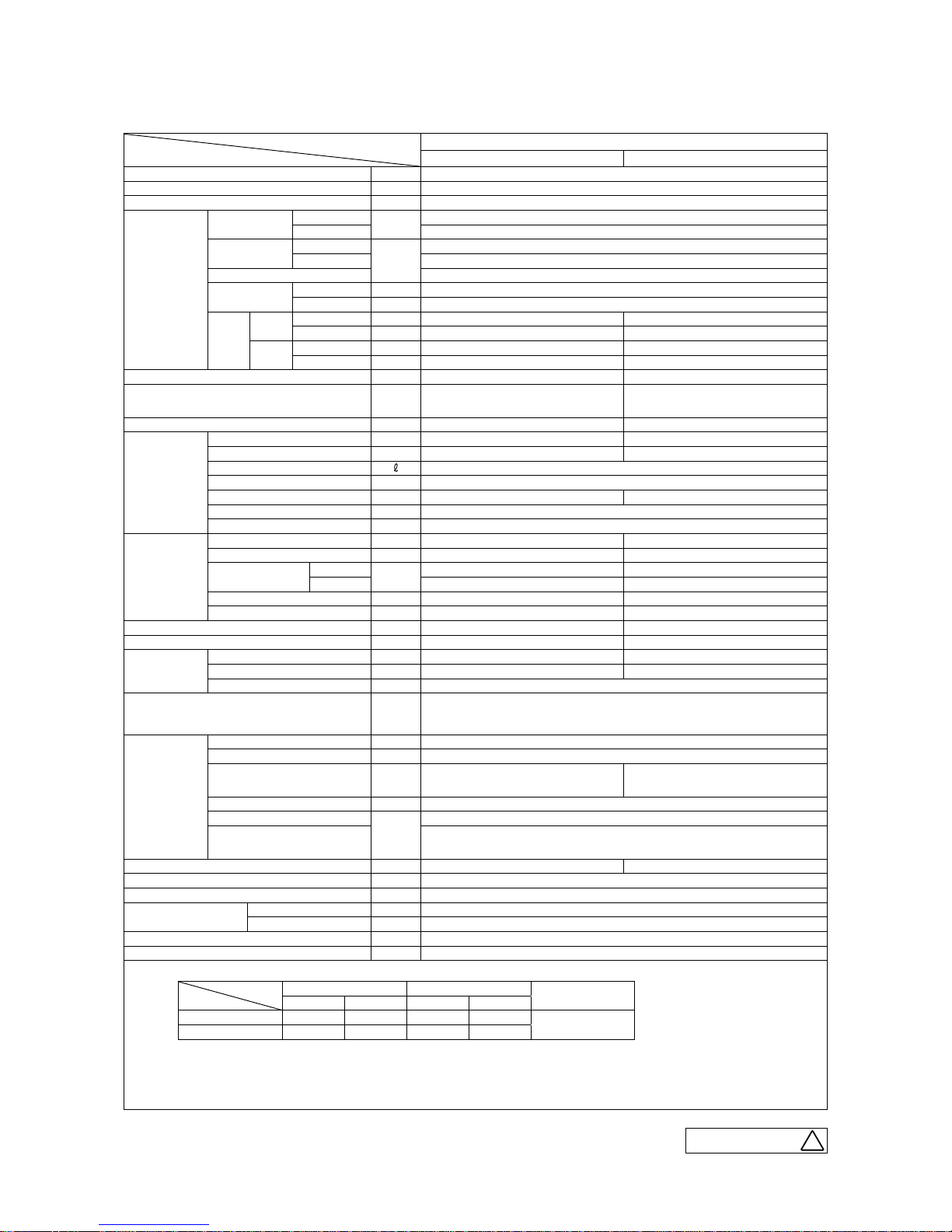
'09•SRK-DB-087D
Model
Item
SRK25ZJ-S
Indoor unit SRK25ZJ-S Outdoor unit SRC25ZJ-SA
Cooling capacity (1) W 2500 (1000 (Min.)
~
2900 (Max.))
Heating capacity (1) W 3200 (1200 (Min.)
~
4200 (Max.))
Power supply 1 Phase, 220
~
240 V, 50Hz
Operation
data (1)
Power
consumption
Cooling
kW
0.62 (0.21
~
0.88)
Heating 0.80 (0.27
~
1.36)
Running
current
Cooling
A
3.2 / 3.1 / 3.0 (220/ 230/ 240 V)
Heating 4.0 / 3.8 / 3.7 (220/ 230/ 240 V)
Inrush current 4.0 / 3.8 / 3.7 (220/ 230/ 240 V)
COP
Cooling 4.03
Heating 4.00
Noise
level
Cooling
Sound level dB (A) Hi: 34 Me: 28 Lo: 21 48
Power level dB 50 60
Heating
Sound level dB (A) Hi: 39 Me: 31 Lo: 24 49
Power level dB 55 61
Exterior dimensions (Height x Width x Depth)
mm
294×798×229 540×780(+62)×290
Exterior appearance
( Munsell color )
Fine snow Stucco white
( 8.0Y 9.3/0.1 ) near equivalent ( 4.2Y 7.5/1.1 ) near equivalent
Net weight
kg
9.5 32
Refrigerant
equipment
Compressor type & Q'ty — RM-B5077MDE1 ( Rotary type ) x 1
Motor (Starting method) kW — 0.75 ( Line starting )
Refrigerant oil 0.35 ( DIAMOND FREEZE MA68 )
Refrigerant (3)
kg
R410A 0.75 (Pre-Charged up to the piping length of 15m)
Heat exchanger Louver fins & inner grooved tubing M fins & inner grooved tubing
Refrigerant control Capillary tubes + Electronic expansion valve
Deice control Microcomputer control
Air handling
equipment
Fan type & Q'ty Tangential fan x 1 Propeller fan x 1
Motor W 38 24
Air flow
Colling
CMM
Hi: 7.9 Me: 6.0 Lo: 5.0 32.1
Heating Hi: 10.6 Me: 6.5 Lo: 5.1 25.6
Fresh air intake Not possible —
Air filter, Quality / Quantity Polypropylene net ( washable ) x 2 —
Shock & vibration absorber —
—
Cushion rubber ( for compressor )
Electric heater Defrost heater 230V 110W
Operation
control
Operation switch Wireless-Remote control —
Room temperature control Microcomputer thermostat —
Operation Display RUN: Green, TIMER: Yellow, HI POWER: Green, 3D AUTO: Green
Safety devices
Compressor overheat protection, Overcurrent protection,
Frost protection, Serial signal error protection, Indoor fan motor error protection,
Heating overload protection( High pressure control ), Cooling overload protection
Installation
data
Refrigerant piping size ( O.D ) mm Liquid line: Ǿ6.35 ( 1/4" ) Gas line:Ǿ9.52 ( 3/8" )
connecting method Flare connecting
Attached length of piping m
Liquid line : 0.53
—
Gas Line : 0.40
Insulation for piping Necessary ( Both sides ), independent
Refrigerant line (one way )length
m
Max.15
Vertical height difference between
outdoor unit and indoor unit
Max.10 ( Outdoor unit is higher )
Max.10 ( Outdoor unit is lower )
Drain hose Connectable ( VP 16 ) —
Power cable —
Recommended breaker size A 16
Connection wiring
Size x Core numbe 1.5mm
2
x 4 cores ( Including earth cable )
Connecting method Terminal block ( Screw fixing type )
Accessories (included) Mounting kit, Clean filter
( Allergen clear filter x 1, Photocatalytic washable deodorizing filter x 1 )
Optional parts Interface kit ( SC-BIKN-E )
Adapted to RoHS directive
Item
Operation
Indoor air temperature Outdoor air temperature
Standards
DB WB DB WB
Cooling 27ºC 19ºC 35ºC 24ºC
ISO-T1 , JIS C 9612
Heating 20ºC — 7ºC 6ºC
Note (1) The data are measured at the following conditions.
(2) This air-conditioner is manufactured and tested in conformity with the ISO.
(3) The operation data are applied to the 220/230/240V districts respectively.
(4) The refrigerant quantity to be charged includes the refrigerant in 15m connecting piping.
(Purging is not required even for the short piping.)
The pipe length is 7.5m.
-
3
-
'10 • SRK-T-098
'09•SRK-DB-087D
Model
Item
SRK25ZJ-S
Indoor unit SRK25ZJ-S Outdoor unit SRC25ZJ-SA
Cooling capacity (1) W 2500 (1000 (Min.)
~
2900 (Max.))
Heating capacity (1) W 3200 (1200 (Min.)
~
4200 (Max.))
Power supply 1 Phase, 220
~
240 V, 50Hz
Operation
data (1)
Power
consumption
Cooling
kW
0.62 (0.21
~
0.88)
Heating 0.80 (0.27
~
1.36)
Running
current
Cooling
A
3.2 / 3.1 / 3.0 (220/ 230/ 240 V)
Heating 4.0 / 3.8 / 3.7 (220/ 230/ 240 V)
Inrush current 4.0 / 3.8 / 3.7 (220/ 230/ 240 V)
COP
Cooling 4.03
Heating 4.00
Noise
level
Cooling
Sound level dB (A) Hi: 34 Me: 28 Lo: 21 48
Power level dB 50 60
Heating
Sound level dB (A) Hi: 39 Me: 31 Lo: 24 49
Power level dB 55 61
Exterior dimensions (Height x Width x Depth)
mm
294×798×229 540×780(+62)×290
Exterior appearance
( Munsell color )
Fine snow Stucco white
( 8.0Y 9.3/0.1 ) near equivalent ( 4.2Y 7.5/1.1 ) near equivalent
Net weight
kg
9.5 32
Refrigerant
equipment
Compressor type & Q'ty — RM-B5077MDE1 ( Rotary type ) x 1
Motor (Starting method) kW — 0.75 ( Line starting )
Refrigerant oil 0.35 ( DIAMOND FREEZE MA68 )
Refrigerant (3)
kg
R410A 0.75 (Pre-Charged up to the piping length of 15m)
Heat exchanger Louver fins & inner grooved tubing M fins & inner grooved tubing
Refrigerant control Capillary tubes + Electronic expansion valve
Deice control Microcomputer control
Air handling
equipment
Fan type & Q'ty Tangential fan x 1 Propeller fan x 1
Motor W 38 24
Air flow
Colling
CMM
Hi: 7.9 Me: 6.0 Lo: 5.0 32.1
Heating Hi: 10.6 Me: 6.5 Lo: 5.1 25.6
Fresh air intake Not possible —
Air filter, Quality / Quantity Polypropylene net ( washable ) x 2 —
Shock & vibration absorber —
—
Cushion rubber ( for compressor )
Electric heater Defrost heater 230V 110W
Operation
control
Operation switch Wireless-Remote control —
Room temperature control Microcomputer thermostat —
Operation Display RUN: Green, TIMER: Yellow, HI POWER: Green, 3D AUTO: Green
Safety devices
Compressor overheat protection, Overcurrent protection,
Frost protection, Serial signal error protection, Indoor fan motor error protection,
Heating overload protection( High pressure control ), Cooling overload protection
Installation
data
Refrigerant piping size ( O.D ) mm Liquid line: Ǿ6.35 ( 1/4" ) Gas line:Ǿ9.52 ( 3/8" )
connecting method Flare connecting
Attached length of piping m
Liquid line : 0.53
—
Gas Line : 0.40
Insulation for piping Necessary ( Both sides ), independent
Refrigerant line (one way )length
m
Max.15
Vertical height difference between
outdoor unit and indoor unit
Max.10 ( Outdoor unit is higher )
Max.10 ( Outdoor unit is lower )
Drain hose Connectable ( VP 16 ) —
Power cable —
Recommended breaker size A 16
Connection wiring
Size x Core numbe 1.5mm
2
x 4 cores ( Including earth cable )
Connecting method Terminal block ( Screw fixing type )
Accessories (included) Mounting kit, Clean filter
( Allergen clear filter x 1, Photocatalytic washable deodorizing filter x 1 )
Optional parts Interface kit ( SC-BIKN-E )
Adapted to RoHS directive
Item
Operation
Indoor air temperature Outdoor air temperature
Standards
DB WB DB WB
Cooling 27ºC 19ºC 35ºC 24ºC
ISO-T1 , JIS C 9612
Heating 20ºC — 7ºC 6ºC
Note (1) The data are measured at the following conditions.
(2) This air-conditioner is manufactured and tested in conformity with the ISO.
(3) The operation data are applied to the 220/230/240V districts respectively.
(4) The refrigerant quantity to be charged includes the refrigerant in 15m connecting piping.
(Purging is not required even for the short piping.)
The pipe length is 7.5m.
B
RWA000Z225
1. SPECIFICATIONS
-
4
-
'10 • SRK-T-098
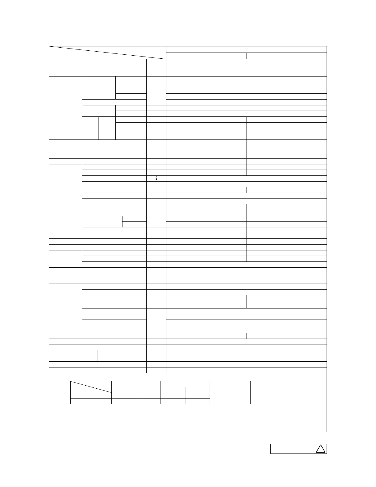
'09•SRK-DB-087D
Model
Item
SRK35ZJ-S
Indoor unit SRK35ZJ-S Outdoor unit SRC35ZJ-SA
Cooling capacity (1) W 3500 (1000 (Min.)
~
3800 (Max.))
Heating capacity (1) W 4000 (1300 (Min.)
~
4800 (Max.))
Power supply 1 Phase, 220
~
240 V, 50Hz
Operation
data (1)
Power
consumption
Cooling
kW
1.01 (0.21
~
1.24)
Heating 1.00 (0.29
~
1.45)
Running
current
Cooling
A
4.9 / 4.7 / 4.5 (220/ 230/ 240 V)
Heating 4.9 / 4.7 / 4.5 (220/ 230/ 240 V)
Inrush current 4.9 / 4.7 / 4.5 (220/ 230/ 240 V)
COP
Cooling 3.47
Heating 4.00
Noise
level
Cooling
Sound level dB (A) Hi: 42 Me: 32 Lo: 22 50
Power level dB 58 62
Heating
Sound level dB (A) Hi: 43 Me: 37 Lo: 25 51
Power level dB 59 63
Exterior dimensions (Height x Width x Depth)
mm
294×798×229 540×780(+62)×290
Exterior appearance
( Munsell color )
Fine snow Stucco white
( 8.0Y 9.3/0.1 ) near equivalent ( 4.2Y 7.5/1.1 ) near equivalent
Net weight
kg
9.5 35
Refrigerant
equipment
Compressor type & Q'ty — RM-B5077MDE1 ( Rotary type ) x 1
Motor (Starting method) kW — 0.90 ( Line starting )
Refrigerant oil 0.35 ( DIAMOND FREEZE MA68 )
Refrigerant (3)
kg
R410A 1.05 (Pre-Charged up to the piping length of 15m)
Heat exchanger Louver fins & inner grooved tubing M fins & inner grooved tubing
Refrigerant control Capillary tubes + Electronic expansion valve
Deice control Microcomputer control
Air handling
equipment
Fan type & Q'ty Tangential fan x 1 Propeller fan x 1
Motor W 38 24
Air flow
Colling
CMM
Hi: 10.1 Me: 6.4 Lo: 5.0 31.5
Heating Hi: 12.8 Me: 9.4 Lo: 6.1 27.8
Fresh air intake Not possible —
Air filter, Quality / Quantity Polypropylene net ( washable ) x 2 —
Shock & vibration absorber —
—
Cushion rubber ( for compressor )
Electric heater Defrost heater 230V 110W
Operation
control
Operation switch Wireless-Remote control —
Room temperature control Microcomputer thermostat —
Operation Display RUN: Green, TIMER: Yellow, HI POWER: Green, 3D AUTO: Green
Safety devices
Compressor overheat protection, Overcurrent protection,
Frost protection, Serial signal error protection, Indoor fan motor error protection,
Heating overload protection( High pressure control ), Cooling overload protection
Installation
data
Refrigerant piping size ( O.D ) mm Liquid line: Ǿ6.35 ( 1/4" ) Gas line: Ǿ9.52 ( 3/8" )
connecting method Flare connecting
Attached length of piping m
Liquid line : 0.53
—
Gas Line : 0.40
Insulation for piping Necessary ( Both sides ), independent
Refrigerant line (one way )length
m
Max.15
Vertical height difference between
outdoor unit and indoor unit
Max.10 ( Outdoor unit is higher )
Max.10 ( Outdoor unit is lower )
Drain hose Connectable ( VP 16 ) —
Power cable —
Recommended breaker size A 16
Connection wiring
Size x Core numbe 1.5mm
2
x 4 cores ( Including earth cable )
Connecting method Terminal block ( Screw fixing type )
Accessories (included) Mounting kit, Clean filter
( Allergen clear filter x 1, Photocatalytic washable deodorizing filter x 1 )
Optional parts Interface kit ( SC-BIKN-E )
Adapted to RoHS directive
Item
Operation
Indoor air temperature Outdoor air temperature
Standards
DB WB DB WB
Cooling 27ºC 19ºC 35ºC 24ºC
ISO-T1 , JIS C 9612
Heating 20ºC — 7ºC 6ºC
Note (1) The data are measured at the following conditions.
(2) This air-conditioner is manufactured and tested in conformity with the ISO.
(3) The operation data are applied to the 220/230/240V districts respectively.
(4) The refrigerant quantity to be charged includes the refrigerant in 15m connecting piping.
(Purging is not required even for the short piping.)
The pipe length is 7.5m.
B
RWA000Z225
-
5
-
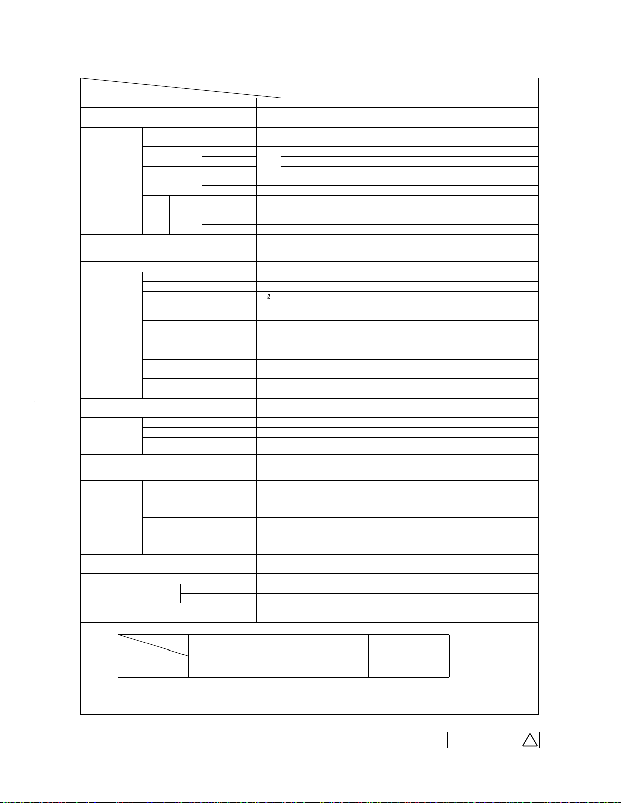
'10 • SRK-T-098
B
RWA000Z229
Model
Item
SRK20ZJX-S
Indoor unit SRK20ZJX-S Outdoor unit SRC20ZJX-SA
Cooling capacity (1) W 2000 (900 (Min.)
~
3100 (Max.))
Heating capacity (1) W 2500 (900 (Min.)
~
4300 (Max.))
Power supply 1 Phase, 220
~
240 V, 50Hz
Operation
data (1)
Power
consumption
Cooling
kW
0.35 (0.19
~
0.70)
Heating 0.45 (0.23
~
1.00)
Running
current
Cooling
A
1.9 / 1.8 / 1.7 (220/ 230/ 240 V)
Heating 2.4 / 2.3 / 2.2 (220/ 230/ 240 V)
Inrush current 2.4 / 2.3 / 2.2 (220/ 230/ 240 V)
COP
Cooling 5.71
Heating 5.56
Noise
level
Cooling
Sound level dB(A) Hi : 39 Me : 30 Lo : 21 47
Power level dB 53 60
Heating
Sound level dB(A) Hi : 38 Me : 33 Lo : 25 47
Power level dB 54 59
Exterior dimensions (Height x Width x Depth) mm 309 x 890 x 220 595 x 780 (+62) x 290
Exterior appearance
(Munsell color)
Fine snow
( 8.0Y 9.3/0.1 ) near equivalent
Stucco white
( 4.2Y 7.5/1.1 ) near equivalent
Net weight kg 15 38
Refrigerant
equipment
Compressor type & Q'ty — RM-B5077MDE1 (Rotary type) x 1
Motor (Starting method) kW — 0.75 (Line starting)
Refrigerant oil
0.35 (DIAMOND FREEZE MA68)
Refrigerant (4) kg R410A 1.2 (Pre-Charged up to the piping length of 15m)
Heat exchanger Louver fins & inner grooved tubing M fins & inner grooved tubing
Refrigerant control Capillary tubes + Electronic expansion valve
Deice control Microcomputer control
Air handling
equipment
Fan type & Q'ty Tangential fan x 1 Propeller fan x 1
Motor 27 24
Air flow
Cooling
CMM
Hi : 11.5 Me : 8.0 Lo : 5.0 29.5
Heating Hi : 12.0 Me : 9.5 Lo : 7.0 27.0
Fresh air intake Not possible —
Air filter, Quality / Quantity Polypropylene net (washable) x 2 —
Shock & vibration absorber — Cushion rubber (for compressor)
Electric heater — Defrost heater 230V 110W
Operation
control
Operation switch Wireless-Remote control —
Room temperature control Microcomputer thermostat —
Operation Display
RUN : Green, TIMER : Yellow, HI POWER : Green,
3D AUTO : Green, ECONO : Blue
Safety devices
Compressor overheat protection, Overcurrent protection,
Frost protection, Serial signal error protection, Indoor fan motor error protection,
Heating overload protection (High pressure control), Cooling overload protection
Installation
data
Refrigerant piping size (O.D) mm Liquid line :φ6.35 (1/4") Gas line :φ9.52 (3/8")
Connecting method Flare connecting
Attached length of piping m
Liquid line : 0.55
Gas line : 0.49
—
Insulation for piping Necessary (Both sides), independent
Refrigerant line (one way) length
m
Max. 15
Vertical height difference between
outdoor unit and indoor unit
Max. 10 (Outdoor unit is higher)
Max. 10 (Outdoor unit is lower)
Drain hose Connectable (VP16) —
Power cable —
Recommended breaker size A 16
Connection wiring
Size x Core number 1.5mm
2
x 4 cores (Including earth cable)
Connecting method Terminal block (Screw fixing type)
Accessories (included)
Mounting kit, Clean filter (Allergen clear filter x 1, Photocatalytic washable deodorizing filter x 1)
Optional parts Interface kit (SC-BIKN-E)
Note (1) The data are measured at the following conditions.
Item
Operation
Indoor air temperature Outdoor air temperature
Standards
DB WB DB WB
Cooling 27˚C 19 ˚C 35˚C 24˚C
ISO -T1, JIS C 9612
Heating 20˚C — 7˚C 6˚C
(2) This air-conditioner is manufactured and tested in conformity with the ISO.
(3) The operation data are applied to the 220/230/240V districts respectively.
(4) The refrigerant quantity to be charged includes the refrigerant in 15m connecting piping.
(Purging is not required even for the short piping.)
The pipe length is 7.5m.
Adapted to RoHS directive
-
6
-
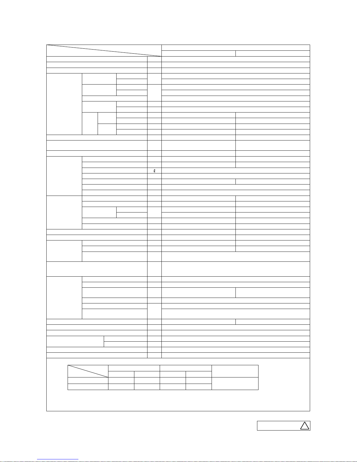
'10 • SRK-T-098
B
RWA000Z229
Model
Item
SRK25ZJX-S
Indoor unit SRK25ZJX-S Outdoor unit SRC25ZJX-SA
Cooling capacity (1) W 2550 (900 (Min.)
~
3200 (Max.))
Heating capacity (1) W 3130 (900 (Min.)
~
4700 (Max.))
Power supply 1 Phase, 220
~
240 V, 50Hz
Operation
data (1)
Power
consumption
Cooling
kW
0.49 (0.19
~
0.82)
Heating 0.595 (0.23
~
1.12)
Running
current
Cooling
A
2.5 / 2.4 / 2.3 (220/ 230/ 240 V)
Heating 3.1 / 2.9 / 2.8 (220/ 230/ 240 V)
Inrush current 3.1 / 2.9 / 2.8 (220/ 230/ 240 V)
COP
Cooling 5.20
Heating 5.26
Noise
level
Cooling
Sound level dB(A) Hi : 41 Me : 31 Lo : 22 47
Power level dB 55 60
Heating
Sound level dB(A) Hi : 41 Me : 34 Lo : 27 47
Power level dB 58 60
Exterior dimensions (Height x Width x Depth) mm 309 x 890 x 220 595 x 780 (+62) x 290
Exterior appearance
(Munsell color)
Fine snow
( 8.0Y 9.3/0.1 ) near equivalent
Stucco white
( 4.2Y 7.5/1.1 ) near equivalent
Net weight kg 15 38
Refrigerant
equipment
Compressor type & Q'ty — RM-B5077MDE1 (Rotary type) x 1
Motor (Starting method) kW — 0.75 (Line starting)
Refrigerant oil
0.35 (DIAMOND FREEZE MA68)
Refrigerant (4) kg R410A 1.2 (Pre-Charged up to the piping length of 15m)
Heat exchanger Louver fins & inner grooved tubing M fins & inner grooved tubing
Refrigerant control Capillary tubes + Electronic expansion valve
Deice control Microcomputer control
Air handling
equipment
Fan type & Q'ty Tangential fan x 1 Propeller fan x 1
Motor W 27 24
Air flow
Cooling
CMM
Hi : 12.5 Me : 9.0 Lo : 5.0 29.5
Heating Hi : 13.0 Me : 10.0 Lo : 7.5 27.0
Fresh air intake Not possible —
Air filter, Quality / Quantity Polypropylene net (washable) x 2 —
Shock & vibration absorber — Cushion rubber (for compressor)
Electric heater — Defrost heater 230V 110W
Operation
control
Operation switch Wireless-Remote control —
Room temperature control Microcomputer thermostat —
Operation Display
RUN : Green, TIMER : Yellow, HI POWER : Green,
3D AUTO : Green, ECONO : Blue
Safety devices
Compressor overheat protection, Overcurrent protection,
Frost protection, Serial signal error protection, Indoor fan motor error protection,
Heating overload protection (High pressure control), Cooling overload protection
Installation
data
Refrigerant piping size (O.D) mm Liquid line :φ6.35 (1/4") Gas line :φ9.52 (3/8")
Connecting method Flare connecting
Attached length of piping m
Liquid line : 0.55
Gas line : 0.49
—
Insulation for piping Necessary (Both sides), independent
Refrigerant line (one way) length
m
Max. 15
Vertical height difference between
outdoor unit and indoor unit
Max. 10 (Outdoor unit is higher)
Max. 10 (Outdoor unit is lower)
Drain hose Connectable (VP16) —
Power cable —
Recommended breaker size A 16
Connection wiring
Size x Core number 1.5mm
2
x 4 cores (Including earth cable)
Connecting method Terminal block (Screw fixing type)
Accessories (included)
Mounting kit, Clean filter (Allergen clear filter x 1, Photocatalytic washable deodorizing filter x 1)
Optional parts Interface kit (SC-BIKN-E)
Note (1) The data are measured at the following conditions.
Item
Operation
Indoor air temperature Outdoor air temperature
Standards
DB WB DB WB
Cooling 27˚C 19 ˚C 35˚C 24˚C
ISO -T1, JIS C 9612
Heating 20˚C — 7˚C 6˚C
(2) This air-conditioner is manufactured and tested in conformity with the ISO.
(3) The operation data are applied to the 220/230/240V districts respectively.
(4) The refrigerant quantity to be charged includes the refrigerant in 15m connecting piping.
(Purging is not required even for the short piping.)
The pipe length is 7.5m.
Adapted to RoHS directive

-
7
-
'10 • SRK-T-098
B
RWA000Z229
Model
Item
SRK35ZJX-S
Indoor unit SRK35ZJX-S Outdoor unit SRC35ZJX-SA
Cooling capacity (1) W 3500 (900 (Min.)
~
4100 (Max.))
Heating capacity (1) W 4300 (900 (Min.)
~
5100 (Max.))
Power supply 1 Phase, 220
~
240 V, 50Hz
Operation
data (1)
Power
consumption
Cooling
kW
0.845 (0.19
~
1.01)
Heating 0.960 (0.23
~
1.35)
Running
current
Cooling
A
4.0 / 3.8 / 3.6 (220/ 230/ 240 V)
Heating 4.6 / 4.4 / 4.2 (220/ 230/ 240 V)
Inrush current 4.6 / 4.4 / 4.2 (220/ 230/ 240 V)
COP
Cooling 4.14
Heating 4.48
Noise
level
Cooling
Sound level dB(A) Hi : 43 Me : 33 Lo : 22 50
Power level dB 58 63
Heating
Sound level dB(A) Hi : 42 Me : 35 Lo : 27 50
Power level dB 59 62
Exterior dimensions (Height x Width x Depth) mm 309 x 890 x 220 595 x 780 (+62) x 290
Exterior appearance
(Munsell color)
Fine snow
( 8.0Y 9.3/0.1 ) near equivalent
Stucco white
( 4.2Y 7.5/1.1 ) near equivalent
Net weight kg 15 38
Refrigerant
equipment
Compressor type & Q'ty — RM-B5077MDE1 (Rotary type) x 1
Motor (Starting method) kW — 0.90 (Line starting)
Refrigerant oil
0.35 (DIAMOND FREEZE MA68)
Refrigerant (4) kg R410A 1.2 (Pre-Charged up to the piping length of 15m)
Heat exchanger Louver fins & inner grooved tubing M fins & inner grooved tubing
Refrigerant control Capillary tubes + Electronic expansion valve
Deice control Microcomputer control
Air handling
equipment
Fan type & Q'ty Tangential fan x 1 Propeller fan x 1
Motor W 27 24
Air flow
Cooling
CMM
Hi : 13.5 Me : 9.5 Lo : 5.0 32.5
Heating Hi : 14.0 Me : 11.0 Lo : 8.0 29.5
Fresh air intake Not possible —
Air filter, Quality / Quantity Polypropylene net (washable) x 2 —
Shock & vibration absorber — Cushion rubber (for compressor)
Electric heater — Defrost heater 230V 110W
Operation
control
Operation switch Wireless-Remote control —
Room temperature control Microcomputer thermostat —
Operation Display
RUN : Green, TIMER : Yellow, HI POWER : Green,
3D AUTO : Green, ECONO : Blue
Safety devices
Compressor overheat protection, Overcurrent protection,
Frost protection, Serial signal error protection, Indoor fan motor error protection,
Heating overload protection (High pressure control), Cooling overload protection
Installation
data
Refrigerant piping size (O.D) mm Liquid line :φ6.35 (1/4") Gas line :φ9.52 (3/8")
Connecting method Flare connecting
Attached length of piping m
Liquid line : 0.55
Gas line : 0.49
—
Insulation for piping Necessary (Both sides), independent
Refrigerant line (one way) length
m
Max. 15
Vertical height difference between
outdoor unit and indoor unit
Max. 10 (Outdoor unit is higher)
Max. 10 (Outdoor unit is lower)
Drain hose Connectable (VP16) —
Power cable —
Recommended breaker size A 16
Connection wiring
Size x Core number 1.5mm
2
x 4 cores (Including earth cable)
Connecting method Terminal block (Screw fixing type)
Accessories (included)
Mounting kit, Clean filter (Allergen clear filter x 1, Photocatalytic washable deodorizing filter x 1)
Optional parts Interface kit (SC-BIKN-E)
Note (1) The data are measured at the following conditions.
Item
Operation
Indoor air temperature Outdoor air temperature
Standards
DB WB DB WB
Cooling 27˚C 19 ˚C 35˚C 24˚C
ISO -T1, JIS C 9612
Heating 20˚C — 7˚C 6˚C
(2) This air-conditioner is manufactured and tested in conformity with the ISO.
(3) The operation data are applied to the 220/230/240V districts respectively.
(4) The refrigerant quantity to be charged includes the refrigerant in 15m connecting piping.
(Purging is not required even for the short piping.)
The pipe length is 7.5m.
Adapted to RoHS directive

-
8
-
'10 • SRK-T-098
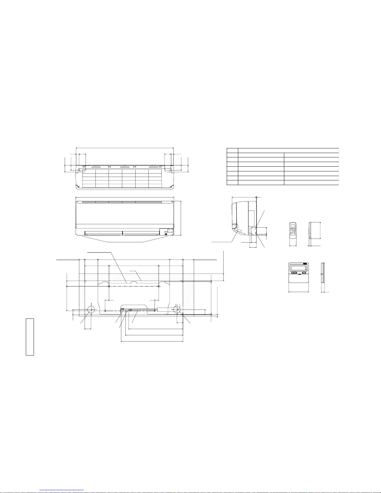
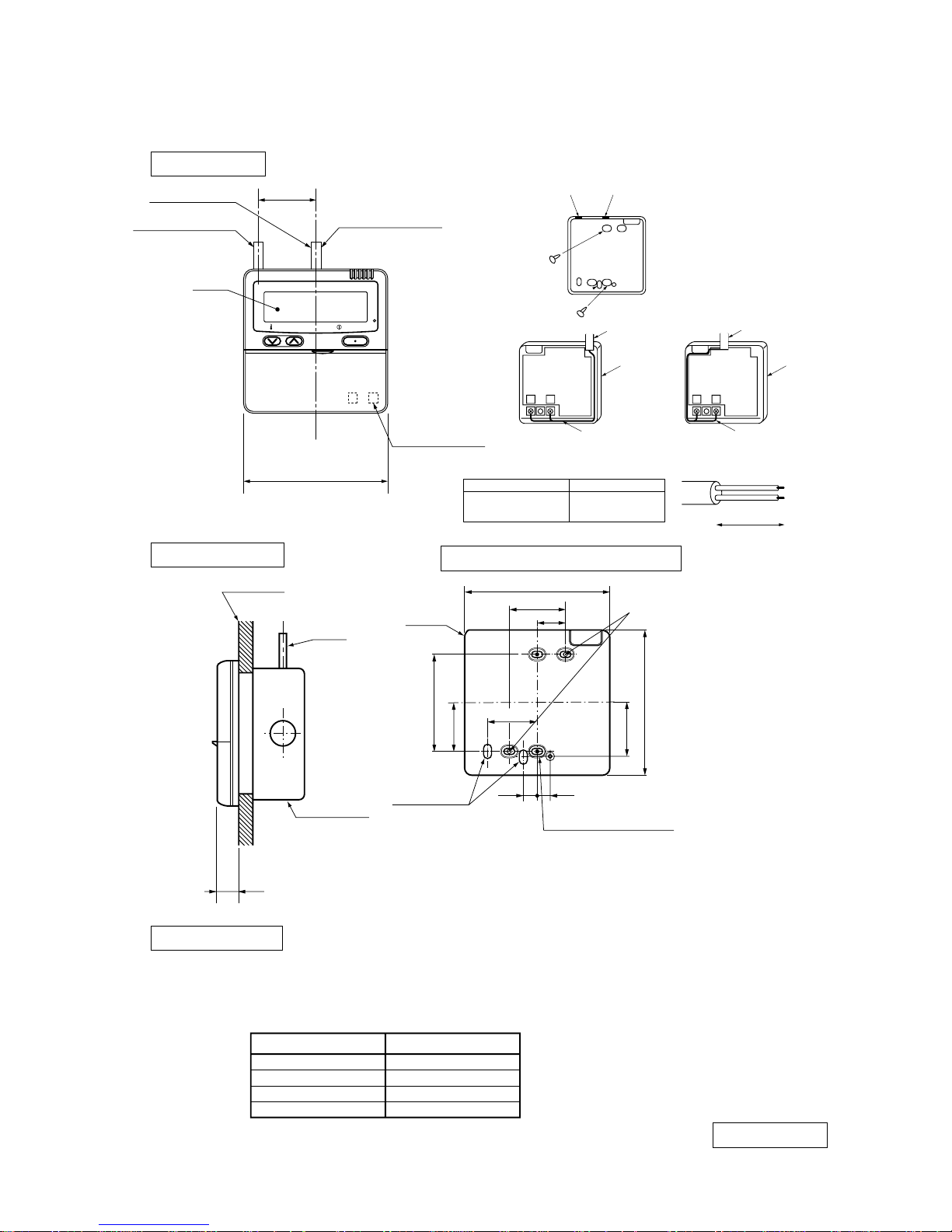
2. EXTERIOR DIMENSIONS
2.1 Indoor units
Models SRK25ZJ-S, 35ZJ-S
Space for installation and service when viewing from the front
Wired - remote controller
㧔Option㧕
Notes㧔1㧕The model name label is attached
ޓޓ ޓ on the underside of the panel.
Wireless remote controller
ޓ 㧔2㧕It takes the interface kit 㧔SC-BIKN-E㧕
ޓޓ ޓ to connect the wired remote controller.
Outlet for down piping
㧔Refer to the above view㧕
Hole on wall for right rear piping
Hole on wall for left rear piping
Gas piping
Outlet for wiring
Drain hose
Liquid piping
F
E
C
D
B
Symbol
A
㧔Ǿ65㧕
VP16
Ǿ6.35㧔1㧛4"㧕㧔Flare㧕
Content
㧔Ǿ65㧕
Ǿ9.52㧔3㧛8"㧕㧔Flare㧕
Outlet for piping㧔on both side㧕
G
Unit:mm
غ120
19
60
150
17.3
G
790
6014.5
45
3160
45
798
294
229 3
45
609
100106.5585106.5
50
48.9
55
47
47
55
403.6
471.6
531.8
F
139 450 209
Unit
D
C
A
E
B
65
15
7.7279.17.2
㧔Service space㧕
㧔Service space㧕
㧔Service space㧕
㧔Service space㧕
Installation plate
RLA000Z051
-
9
-
'10 • SRK-T-098
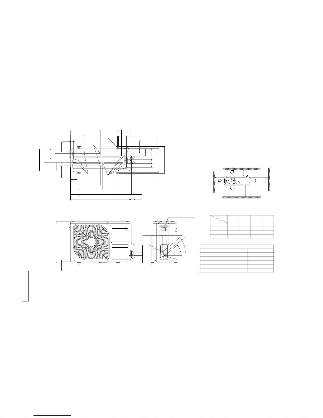
Models SRK20ZJX-S, 25ZJX-S, 35ZJX-S
G
F
Hole on wall for right rear piping
Hole on wall for left rear piping
Gas piping
Outlet for wiring
Drain hose
Liquid piping
F
E
C
D
B
Symbol
A
㧔Ǿ65㧕
VP16
Ǿ6.35㧔1㧛4"㧕㧔Flare㧕
Content
㧔Ǿ65㧕
Unit:mm
Space for installation and service when viewing from the front
Outlet for down piping
㧔Refer to the above view㧕
Outlet for piping㧔on both side㧕
G
D C
A
E
B
Wired - remote controller
㧔Option㧕
Notes㧔1㧕The model name label is attached
ޓޓ ޓ on the underside of the panel.
Wireless remote controller
ޓ 㧔2㧕It takes the interface kit 㧔SC-BIKN-E㧕
ޓޓ ޓ to connect the wired remote controller.
Terminal block
Ǿ9.52㧔3㧛8"㧕㧔Flare㧕
881.9
59.926 20.959.9
46.5
61.5
46.5
61.5
890
309
9 61.5
3220
50 120 650 120 100
220 450 220
35 35
48.9222.5
48
48
5.7 295.4 7.9
15
㧔Service space㧕
65
Unit
54
46.5
㧔Service space㧕
㧔Service space㧕 㧔Service space㧕
Installation plate
491.1
520.8
559.1
58
غ
120
19
61.5
60
150
17.3
RKY000Z053
-
10
-
'10 • SRK-T-098
Notes
㧔1㧕 It must not be surrounded by walls on the four sides.
㧔2㧕 The unit must be fixed with anchor bolts. An anchor bolt must not
protrude more the 15mm.
㧔3㧕 Where the unit is subject to strong winds, lay it in such
a direction that the blower outlet faces perpendicularly
to the dominant wind direction.
㧔4㧕 Leave 1m or more space above the unit.
㧔5㧕 A wall in front of the blower outlet must not exceed the units height.
㧔6㧕 The model name label is attached on the lower right comer of the front panel.
L4
L3
L1
Intake
Service
space
Intake
Outlet
Minimum installation space
L2
L2
L3
L4
L1
100
100
250
Open
㧵 㧵㧵
Open
250
80
280
㧵㧵㧵
280
Open
80
75
Examples of
Dimensions
installation
㧵㨂
180
Open
80
Open
Ǿ9.52㧔3㧛8"㧕㧔Flare㧕
Content
C Pipe㧛cable draw-out hole
D1
E Anchor bolt hole
Drain discharge hole
Symbol
B
A Service valve connection㧔gas side㧕
M10 × 4places
Ǿ20 × 2places
D2 Drain discharge hole
Ǿ16 × 9places
Service valve connection㧔liquid side㧕
Ǿ6.35㧔1㧛4"㧕㧔Flare㧕
Unit:mm
C
40°
40°
RCV000Z008
2.2 Outdoor units
Models SRC25ZJ-SA, 35ZJ-SA
40°
40°
138.4 33.5
Terminal block
A
C
B
97.7 42.5
15.8
540
63.4
390.6
390.6
69.4
111.6 510 158.4
780 61.9
17.9
14.8 312.5 24.3
351.6
50.6
12
290
4949 142.6
54.1
48.1
112.2
422
86.6
179.6
176.4
42.9
130.9
38.8
106.3
97.6
E
D
1
D2
D
2
-
11
-
'10 • SRK-T-098
A
RCV000Z007
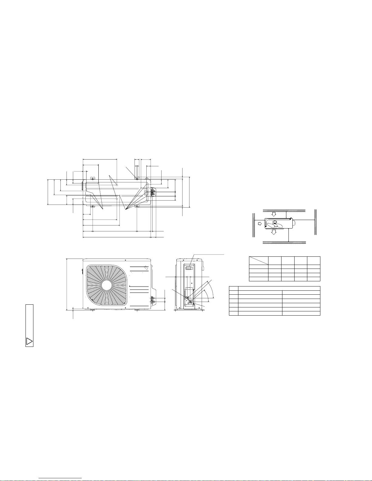
Models SRC20ZJX-SA, 25ZJX-SA, 35ZJX-SA
L2
Intake
Outlet
Intake
L3
L1
Minimum installation space
Service
space
( )
L4
L2
L3
L4
L1
100
100
250
Open
I
II
Open
250
80
280
III
280
Open
80
75
Examples of
Dimensions
installation
IV
180
Open
80
Open
Notes
(1) It must not be surrounded by walls on the four sides.
(2) The unit must be fixed with anchor bolts. An anchor bolt must not
protrude more the 15mm.
(3) Where the unit is subject to strong winds, lay it in such
a direction that the blower outlet faces perpendicularly
to the dominant wind direction.
(4) Leave 1m or more space above the unit.
(5) A wall in front of the blower outlet must not exceed the units height.
(6) The model name label is attached on the lower right corner of the front panel.
φ9.52(3/8")(Flare)
Content
C Pipe/cable draw-out hole
E Anchor bolt hole
Drain discharge hole
Symbol
B
A Service valve connection(gas side)
M10 × 4places
φ20 × 2places
Service valve connection(liquid side)
φ6.35(1/4")(Flare)
D1
Drain discharge hole
φ16 × 9places
D2
Unit:mm
40°
40°
138.4 33.5
Terminal block
C
B
A
97.7 42.5
15.8
595
63.4
390.6
390.6
69.4
111.6 510 158.4
780 61.9
17.9
14.8 312.5 24.3
351.6
50.6
12
290
4949 142.6
54.1
48.1
112.2
422
86.6
179.6
176.4
42.9
130.9
38.8
106.3
97.6
E
D
1
D
2
D
2
-
12
-
'10 • SRK-T-098
2.3 Remote controller
(a) Wireless remote controller
Unit: mm
60
17.3
150
٨
The wireiess remote controller in the following figure shows for the SRK series.
-
13
-
'10 • SRK-T-098
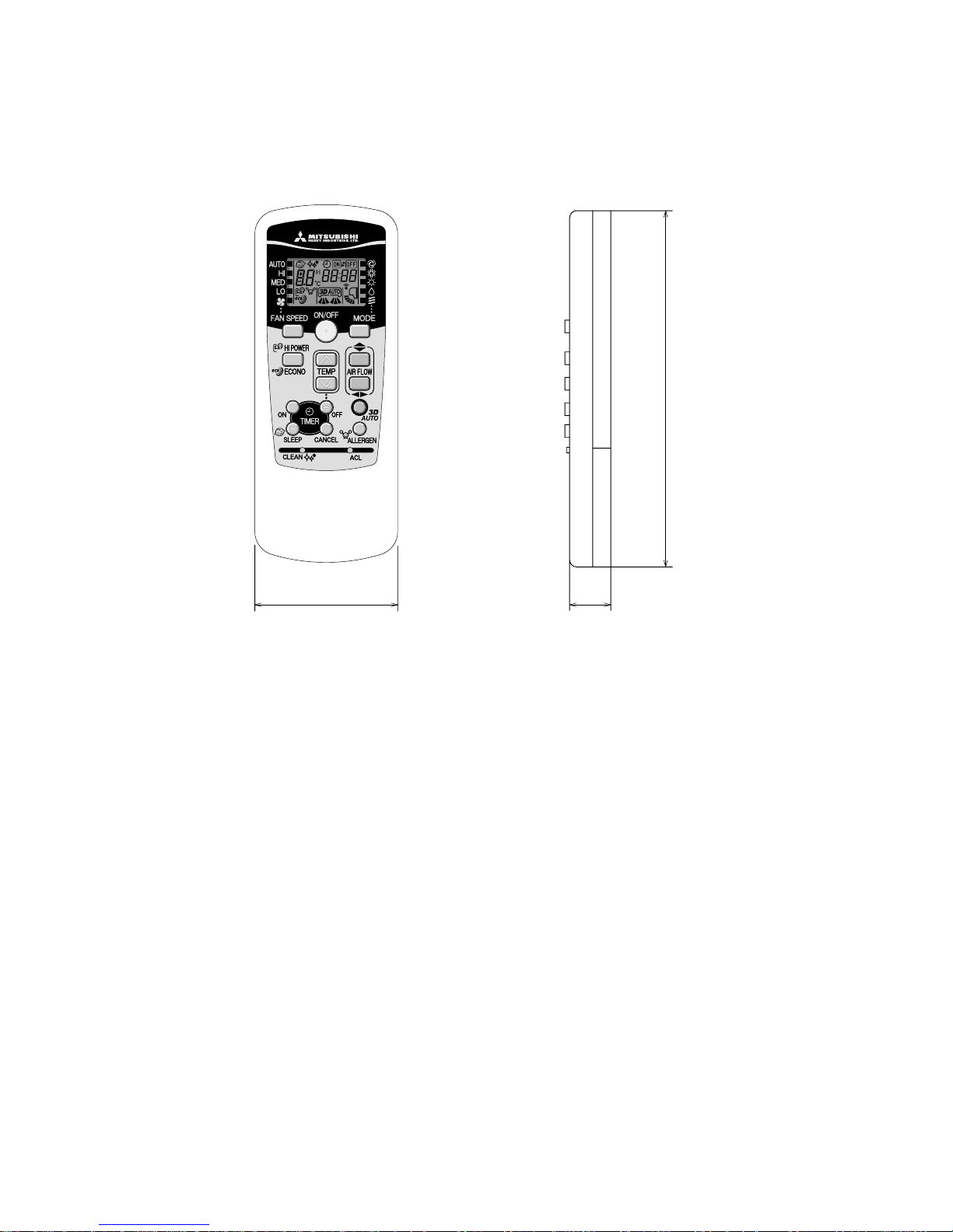
(b) Wired remote controller (option parts)
PJZ000Z274
TEMP ON/OFF
48
غ120
L C D
Wall surface
Wiring
Electrical box
䋨Not included䋩
19
Wiring specifications
Exposed mounting
23
46
11.5 11
Remote
control
outline
120
45
83.5
42
120
Remote control installation dimensions
Wiring oulet
Installation hole
12×7 Slot hole
9.5×5 Slot hole 䋨4places䋩
䋨1䋩 Installation screw for remote control
M4 Screw (2 pieces)
44
(1) If the prolongation is over 100m, change to the size below.
But, wiring in the remote controller case should be under 0.5mm
2
. Change the wire size outside of
the case according to wire connecting. Waterproof treatment is necessary at the wire connecting
section. Be careful about contact failure.
Length Wiring thickness
100 to 200m
0.5mm
2
×2 cores
0.75mm
2
×2 cores
1.25mm
2
×2 cores
2.0mm
2
×2 cores
Under 300m
Under 400m
Under 600m
Upper part
Lower part
Lower case
Sheath
Upper cace
Board
Wiring
Upper
Lower
X Y
Sheath
Upper cace
Board
Wiring
Upper
Lower
YX
Tighten the screws after
cutting off the thin part of
screw mounting part.
Embedded mounting
The peeling-off length of sheath
The peeling-off length
of sheath
In case of pulling out from
upper left
In case of pulling out
from upper left
In case of pulling out
from upper left
X wiring : 170mm
Y wiring : 190mm
Pulling out from center
X wiring : 215mm
Y wiring : 195mm
Pulling out from upper left
In case of pulling out from center
In case of pulling out
from center
In case of pulling out
from center
Wiring outlet
Cut off the upper thin part of remote control lower case with a nipper or knife,
and grind burrs with a file etc.
0.3mm2×2 cores.
X, Y Terminal block
Attach M3 screw
with washer
Unit:mm
-
14
-
'10 • SRK-T-098
250V 3.15A
PRINTED
CNF CNE
CNX
CNG
4
CNU
1 3 65
35,50
CNY
M M M
5 5
U
2 8
2
t
o
CNS
CNM
M
5
TO OUTDOOR
S/N
J
L
G
1
CIRCUIT
BOARD
INTERFACE KIT
RDBKWHYBL
WIRELESS
DISPLAY
BACK-UP SW
UNIT
BKWHRD
Y/G
HEAT
EXCHANGER
2/N
3
Y/G
HD
ONLY
t
o
2
t
o
R-AMP
2
HEAT
EXCHANGER
5
FM
I
SM
I
LM
1
LM
2
F
Va
Th
I
Th
2
Th
3
T
DS
㨪
㨪
Blue
BlackBK
Red
BL
RD
WhiteWH
Yellow㧛GreenY㧛G
ColorMark
Heat exch. sensor
Fan motor
Room temp. sensor
Flap motor
Diode stackDS
FuseF
Connector
CNE-CNY
FM
I
Terminal blockT
Description
Item
VaristorVa
LM
1,2
SM
I
Louver motor
Th
I
Th
2,3
YellowY
Humidity sensor
HD
Power Source
1 Phase
220㧛230㧛240V 50Hz
RWA000Z226
3. ELECTRICAL WIRING
3.1 Indoor units
Models SRK25ZJ-S, 35ZJ-S
-
15
-
'10 • SRK-T-098
Models SRK20ZJX-S, 25ZJX-S, 35ZJX-S
250V
F
G
3.15A
S㧛N
Va
CNU
CNS
INTERFACE KIT
SC-BIKN-E
CNG
CNE
DISPLAY
WIRELESS RECEIVER
J
CNF
U
M
HEAT
1
3
4
5
6
BACK-UP SW
5
2
12
EXCHANGER
L
Th1
BOARD
CIRCUIT
PRINTED
LS
CNY
CNX2
CNX1
M
M
M
M
M
5
5
5
5
5
5
5
5
5 5
IM
RD
WH
RD
WH
BK
BL
Y
Y㧛G
BK
t
Th2 1
Th2 2
Th3
LM
1
LM
2
SM
1
SM
2
FM
I
DS
t
t
TO OUTDOOR UNIT
HEAT
EXCHANGER
1
2㧛N
3
POWER WIRES
SIGNAL WIRE
1
2/N
3
Power source
1 phase 220 - 240 V 50Hz
T
Color Marks
Blue
BlackBK
Red
BL
RD
WhiteWH
Yellow㧛GreenY㧛G
YellowY
ColorMark
Heat exch. sensor
Humidity sensor 㧔50,60 only㧕
Fan motor
Room temp. sensor
Flap motor
Th1
Th2
Th3
Diode stackDS
FuseF
Connector
CNE-CNY
FM
I
Terminal blockT
Louver motor
LM
1,2
SM
1,2
1,2
Limit switchLS
Inlet motor
IM
Description
Item
VaristorVa
RWA000Z227
-
16
-
'10 • SRK-T-098
3.2 Outdoor units
Models SRC25ZJ-SA, 35ZJ-SA
20ZJX-SA, 25ZJX-SA, 35ZJX-SA
RWC000Z226
Color
RD
Mark
OrangeOR
Yellow㧛GreenY㧛G
BlackBK
YellowY
WhiteWH
Red
DescriptionItem
Connector
CNEEV㨪CN20S
Electric expansion valve㧔coil㧕EEV
Fan motorFMo
ReactorL
Terminal blockT
Compressor motorCM
Solenoid valve for 4 way valve20S
Heat exchanger sensor㧔outdoor unit㧕TH1
Outdoor air temp.sensorTH2
TH3 Discharge pipe temp.sensor
HeaterH
Heater protector26H
Fuse
F1-4
20
Model
Power cable, indoor-outdoor connecting wires
Switchgear of Circuit breaker capacity which is calculated from MAX. over current should be chosen
Note (1) : Figure in ( ) is for models SRC20, 25, 35ZJX-SA.
along the regulations in each country.
The cable specifications are based on the assumption that a metal or plastic conduit is used with no
more than three cables contained in a conduit and a voltage drop is 2%. For an installation falling
outside of these conditions, please follow the internal cabling regulations. Adapt it to the regulation
in effect in each country.
25 9 (8) 2.0 32
1.5mm2 x 3 1.5mm
2
35
=?
0
1㨪220㨺240V 50Hz1㨪220V 60Hz
POWER SOURCE
㧔BK㧕
C-2
G1
㧔RD㧕
㧔;㧛)㧕
S.IN㧔WH㧕
R.IN
㧔BK㧕
㧔WH㧕
㧔RD㧕
PWB ASSY
250V 20A
F2
F3 250V 1A
F4
250V 10A
F1
250V 2A
CIRCUIT
PAM
SWITCHING POWER
CIRCUIT
NW
NV
NU
P
W
V
U
TRANSISTOR
POWER
W
V
U
FILTER
NOISE
CN20S
CNTH
CNEEV
CNFAN
M
M
3㨪
250V 15A
㧔Y㧛G㧕
T1
T2
㧔14㧕
㧔Y㧕
M
20S
TH1 TH2 TH3 EEV
FMo
CM
L
L
N
0
T
TO INDOOR UNIT
POWER WIRES
SIGNAL WIRE
26H
H
CNHEAT
MAX running current Power cable size
㧔mm 㧕
2
㧔A㧕
Power cable length
㧔m㧕
indoor-outdoor
wire size x number
Earth wire size
*
RWC000Z239
-
17
-
'10 • SRK-T-098
'09•SRK-DB-087D
(Indoor Unit)
Model SRK25ZJ-S
Noise
Level
Cooling 34 dB(A)
Heating 39 dB(A)
×
......
Cooling
Heating
Model SRK25ZJ-S
(Outdoor Unit)
Model SRC25ZJ-SA
Noise
Level
Cooling 48 dB(A)
Heating 49 dB(A)
×
......
Cooling
Heating
Condition ISO-T1, JIS C9612
10
20
30
40
50
60
70
63 125 250 500 1000 2000 4000 8000
1000 2000 4000 8000
10
20
30
40
50
60
70
N50
N30
N40
N60
N70
N20
10
20
30
40
50
60
70
63 125 250 500
10
20
30
40
50
60
70
N50
N30
N40
N60
N70
N20
Sound Pressure Level (dB)
(standard 2×10
-5
Pa)
Sound Pressure Level (dB)
(standard 2×10
-5
Pa)
Mid Octave Band frequency (Hz)
Mid Octave Band frequency (Hz)
Model SRK25ZJ-S
4. NOISE LEVEL
-
18
-
'10 • SRK-T-098
'09•SRK-DB-087D
(Indoor Unit)
Model SRK35ZJ-S
Noise
Level
Cooling
42 dB(A)
Heating
43 dB(A)
×
......
Cooling
Heating
Model SRK35ZJ-S
(Outdoor Unit)
Model SRC35ZJ-SA
Noise
Level
Cooling
50 dB(A)
Heating
51 dB(A)
×
......
Cooling
Heating
Condition ISO-T1, JIS C9612
10
20
30
40
50
60
70
63 125 250 500 1000 2000 4000 8000
63 125 250 500 1000 2000 4000 8000
10
20
30
40
50
60
70
N50
N30
N40
N60
N70
N20
10
20
30
40
50
60
70
10
20
30
40
50
60
70
N50
N30
N40
N60
N70
N20
Sound Pressure Level (dB)
(standard 2×10
-5
Pa)
Sound Pressure Level (dB)
(standard 2×10
-5
Pa)
Mid Octave Band frequency (Hz)
Mid Octave Band frequency (Hz)
Model SRK35ZJ-S
-
19
-
'10 • SRK-T-098
(Indoor Unit)
Model SRK20ZJX-S
Noise
Level
Cooling 39 dB(A)
Heating 38 dB(A)
×
......
Cooling,
Heating
Model SRK20ZJX-S
10
20
30
40
50
60
70
63 125 250 500 1000 2000 4000 8000
Mid Octave Band frequency (Hz)
Sound Pressure Level (dB)
(standard 2×10
-5
Pa)
10
20
30
40
50
60
70
N50
N30
N40
N60
N70
N20
(Outdoor Unit)
Model SRC20ZJX-SA
Noise
Level
Cooling 47 dB(A)
Heating 47 dB(A)
10
20
30
40
50
60
70
63 125 250 500 1000 2000 4000 8000
Mid Octave Band frequency (Hz)
Sound Pressure Level (dB)
(standard 2×10
-5
Pa)
10
20
30
40
50
60
70
N50
N30
N40
N60
N70
N20
×
......
Cooling, Heating
Condition ISO-T1,JIS C9612
-
20
-
'10 • SRK-T-098
(Indoor Unit)
Model SRK25ZJX-S
Noise
Level
Cooling 41 dB(A)
Heating 41 dB(A)
×
......
Cooling,
Heating
Model SRK25ZJX-S
10
20
30
40
50
60
70
63 125 250 500 1000 2000 4000 8000
Mid Octave Band frequency (Hz)
Sound Pressure Level (dB)
(standard 2×10
-5
Pa)
10
20
30
40
50
60
70
N50
N30
N40
N60
N70
N20
(Outdoor Unit)
Model SRC25ZJX-SA
Noise
Level
Cooling 47 dB(A)
Heating 47 dB(A)
10
20
30
40
50
60
70
63 125 250 500 1000 2000 4000 8000
Mid Octave Band frequency (Hz)
Sound Pressure Level (dB)
(standard 2×10
-5
Pa)
10
20
30
40
50
60
70
N50
N40
N60
N70
N20
N30
×
......
Cooling, Heating
Condition ISO-T1,JIS C9612
-
21
-
'10 • SRK-T-098
(Indoor Unit)
Model SRK35ZJX-S
Noise
Level
Cooling 43 dB(A)
Heating 42 dB(A)
×
......
Cooling,
Heating
Model SRK35ZJX-S
(Outdoor Unit)
Model SRC35ZJX-SA
Noise
Level
Cooling 50 dB(A)
Heating 50 dB(A)
×
......
Cooling,
Heating
Condition ISO-T1,JIS C9612
10
20
30
40
50
60
70
63 125 250 500 1000 2000 4000 8000
Mid Octave Band frequency (Hz)
Sound Pressure Level (dB)
(standard 2×10
-5
Pa)
10
20
30
40
50
60
70
N50
N30
N40
N60
N70
N20
10
20
30
40
50
60
70
63 125 250 500 1000 2000 4000 8000
Mid Octave Band frequency (Hz)
Sound Pressure Level (dB)
(standard 2×10
-5
Pa)
10
20
30
40
50
60
70
N50
N30
N40
N60
N70
N20
-
22
-
'10 • SRK-T-098
'09•SRK-DB-087D
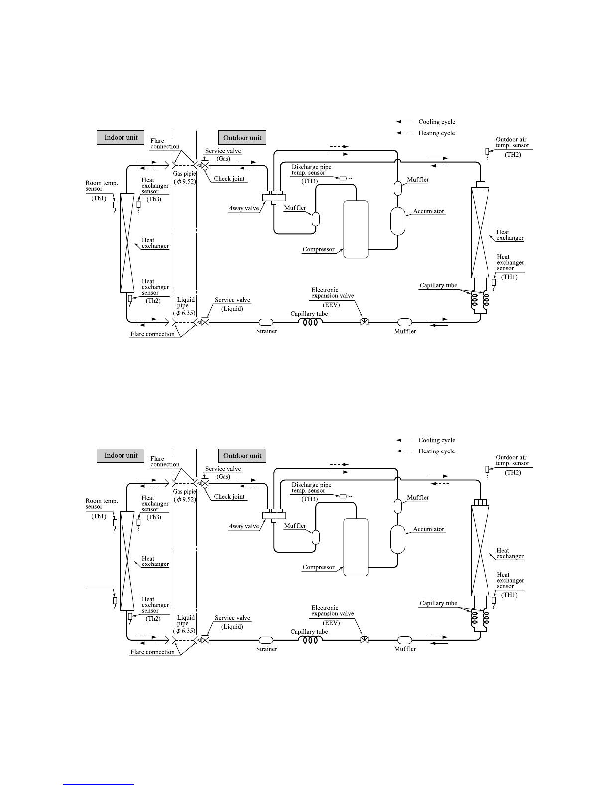
5 PIPING SYSTEM
Model SRK25ZJ-S / SRC25ZJ-SA
Model SRK35ZJ-S / SRC35ZJ-SA
Humidity
sensor
(HD)
5. PIPING SYSTEM

-
23
-
'10 • SRK-T-098
Models SRK20ZJX-S, 25ZJX-S, 35ZJX-S
Indoor unit
Outdoor unit
Flare
connection
Flare connection
Liquid
pipe
(φ6.35)
Gas pipie
(φ9.52)
Service valve
Heat
exchanger
Heat
exchanger
sensor
Electronic
expansion valve
(Liquid)
Strainer
Capillary tube
Outdoor air
temp. sensor
Muffler
Muffler
Compressor
Accumlator
Discharge pipe
temp. sensor
Cooling cycle
Heating cycle
Check joint
4way valve
Service valve
Heat
exchanger
sensor
(Th2
2)
(TH3)
Room temp.
sensor
(Th1)
(Th2
1)
(
Gas
)
(TH2)
Heat
exchanger
sensor
(TH1)
(EEV)
Capillary tube
Heat
exchanger
Model SRK50ZJ-S
Indoor unit
Outdoor unit
Flare
connection
Flare connection
Liquid
pipe
(φ6.35)
Gas pipie
(φ12.7)
Service valve
Heat
exchanger
Heat
exchanger
sensor
Electronic
expansion valve
(Liquid)
Strainer
Receiver
Muffler
Capillary tube
Outdoor air
temp. sensor
Muffler
Muffler
Compressor
Discharge pipe
temp. sensor
Cooling cycle
Heating cycle
Check joint
4way valve
Service valve
Heat
exchanger
sensor
(Th3)
(TH3)
Room temp.
sensor
(Th1)
(Th2)
(
Gas
)
(TH2)
Heat
exchanger
sensor
(TH1)
(EEV)
Capillary tube
Heat
exchanger
Humidity
sensor
(HD)
Muffler
Models SRK20ZJX-S, 25ZJX-S, 35ZJX-S / SRC20ZJX-SA, 25ZJX-SA, 35ZJX-SA
-
24
-
'10 • SRK-T-098
RANGE OF USAGE & LIMITATIONS
Indoor return air temperature
(Upper, lower limits)
Refrigerant line (one way) length
Power source voltage Rating ±10%
Voltage at starting Min. 85% of rating
Frequency of ON-OFF cycle
Max. 4 times/h
(Inching prevention 10 minutes)
ON and OFF interval Min. 3 minutes
Outdoor air temperature
(Upper, lower limits)
Vertical height difference between
outdoor unit and indoor unit
Max. 15m
Max. 10m
(Outdoor unit is higher)
Max. 10m
(Outdoor unit is lower)
Item
Models
All models
Cooling operation : Approximately 18 to 32℃ D.B.
Heating operation : Approximately 10 to 27℃ D.B.
(Refer to the selection chart)
Cooling operation : Approximately -15 to 46℃ D.B.
Heating operation : Approximately -15 to 21℃ D.B.
(Refer to the selection chart)
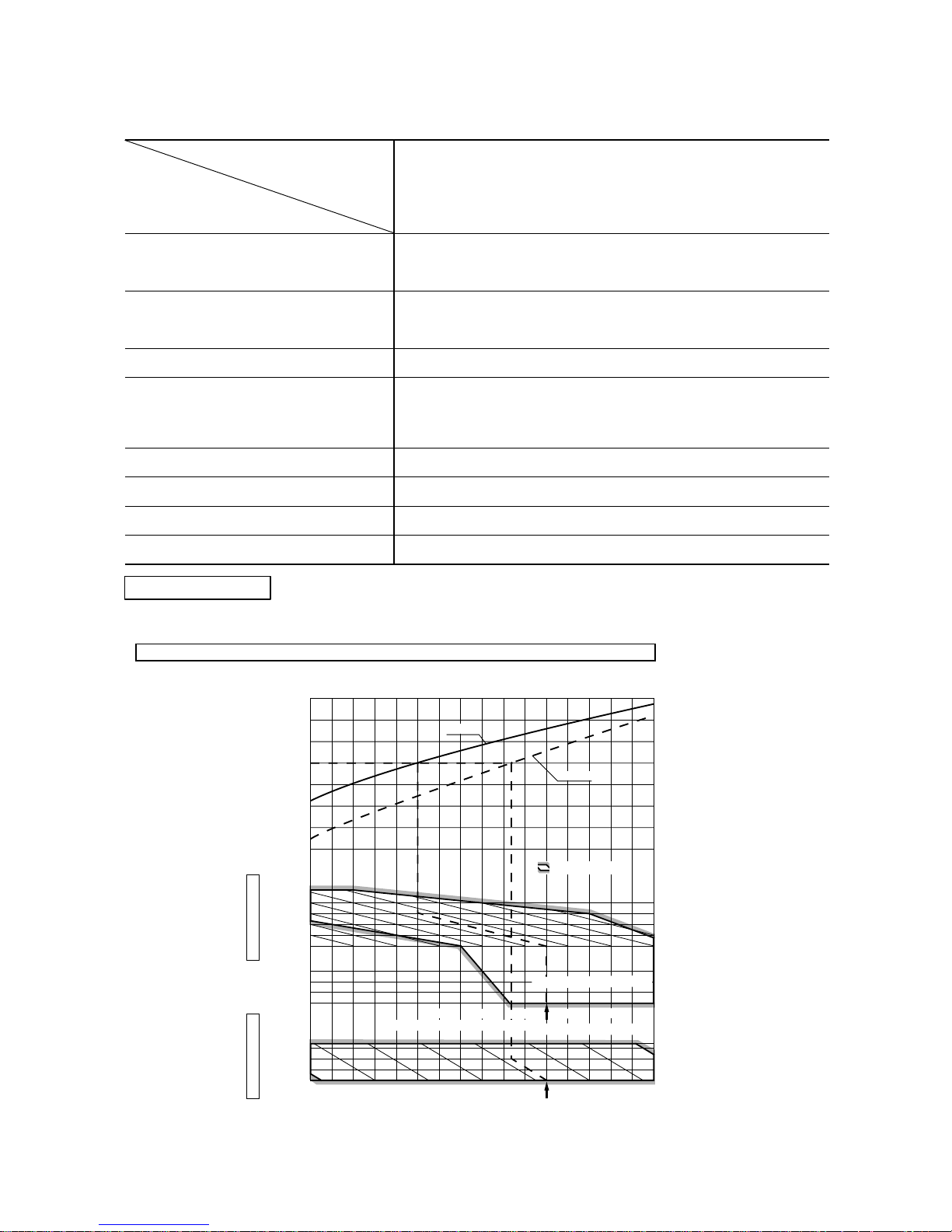
Selection chart
Correct the cooling and heating capacity in accordance with the conditions as follows. The net cooling and heating capacity can be
obtained in the following way.
Net capacity = Capacity shown on specication × Correction factors as follows.
(1) Coefcient of cooling and heating capacity in relation to temperatures
0.6
0.7
0.8
0.9
1.0
1.2
1.1
1.3
0
-5
-10
-15
24
26
20
25
30
35
40
46
10
15
20
25
27
Outdoor air W.B. temperature °C W.B.
-15 -10 -5 0 5 10 15
.
Cooling operation
Outdoor air D.B.
temperature
°C D. B.
Coefficient of cooling
&
Heating capacity in
relation to temperature
Heating operation
Indoor air D.B.
temperature
°C D. B.
ISO-T1 Standard Condition
Depends on installed situation
ISO-T1 Standard Condition
2220181614
Indoor air W.B. temperature °C W.B
Applicable range
Cooling
Heating
6. RANGE OF USAGE & LIMITATIONS
-
25
-
'10 • SRK-T-098
'09•SRK-DB-087D
(2) Correction of cooling and heating capacity in relation to one way length of refrigerant piping
,WLVQHFHVVDU\WRFRUUHFWWKHFRROLQJDQGKHDWLQJFDSDFLW\LQUHODWLRQWRWKHRQHZD\SLSLQJOHQJWKEHWZHHQWKHLQGRRUDQGRXWGRRU
XQLWV
(3) Correction relative to frosting on outdoor heat exchanger during heating
,QDGGLWLRQVWRWKHIRUHJRLQJFRUUHFWLRQVWKHKHDWLQJFDSDFLW\QHHGVWREHDGMXVWHGDOVRZLWKUHVSHFWWRWKHIURVWLQJRQWKH
RXWGRRUKHDWH[FKDQJHU
How to obtain the cooling and heating capacity
([DPSOH7KHQHWFRROLQJFDSDFLW\RIWKHPRGHO65.=-6ZLWKWKHSLSLQJOHQJWKRIPLQGRRUZHWEXOEWHPSHUDWXUHDWÛ&
DQGRXWGRRUGU\EXOEWHPSHUDWXUHÛ&LV1HWFRROLQJFDSDFLW\ =:
/HQJWKP )DFWRUE\DLU
WHPSHUDWXUHV
Piping length [m]
Cooling
Heating
7
1.0
1.0
10
0.99
1.0
15
0.975
1.0
20
0.965
1.0
25
0.95
1.0
30
0.935
1.0
65.=-6
Air inlet temperature of
outdoor unit in °C WB
Adjustment coefficient
-15
0.95 0.95 0.94 0.93 0.91 0.88 0.86 0.87 0.92 1.00
-10 -9 -7 -5 -3 -1 1 3
5 or more
-
26
-
'10 • SRK-T-098
Air flow
Outdoor
air temp.
Indoor air temp
21˚CDB 23˚CDB 26˚CDB 27˚CDB 28˚CDB 31˚CDB 33˚CDB
14˚CWB 16˚CWB 18˚CWB 19˚CWB 20˚CWB 22˚CWB 24˚CWB
TC SHC TC SHC TC SHC TC SHC TC SHC TC SHC TC SHC
Hi
7.9
(m
3
/min)
10
2.82 2.23 2.95 2.19 3.06 2.27 3.11 2.24 3.16 2.21 3.26 2.28 3.34 2.21
12 2.77 2.20 2.90 2.17 3.01 2.25 3.07 2.22 3.12 2.20 3.22 2.27 3.31 2.20
14 2.71 2.17 2.85 2.14 2.97 2.23 3.03 2.21 3.08 2.18 3.18 2.25 3.28 2.19
16 2.66 2.15 2.80 2.12 2.92 2.21 2.98 2.19 3.04 2.16 3.15 2.24 3.24 2.18
18 2.60 2.12 2.74 2.09 2.88 2.19 2.94 2.17 2.99 2.14 3.11 2.22 3.20 2.17
20 2.55 2.09 2.68 2.07 2.83 2.17 2.89 2.14 2.95 2.12 3.07 2.21 3.17 2.15
22 2.49 2.06 2.63 2.04 2.78 2.14 2.84 2.12 2.90 2.10 3.02 2.20 3.13 2.14
24 2.43 2.03 2.57 2.01 2.72 2.12 2.80 2.11 2.85 2.08 2.98 2.18 3.08 2.13
26 2.37 2.00 2.51 1.98 2.67 2.10 2.74 2.09 2.80 2.07 2.93 2.16 3.04 2.11
28 2.31 1.97 2.44 1.96 2.61 2.08 2.69 2.07 2.75 2.05 2.89 2.14 3.00 2.10
30 2.24 1.94 2.38 1.92 2.56 2.05 2.64 2.05 2.70 2.03 2.84 2.13 2.95 2.08
32 2.18 1.91 2.31 1.89 2.50 2.03 2.58 2.03 2.64 2.01 2.79 2.11 2.90 2.07
34 2.11 1.88 2.25 1.87 2.44 2.01 2.53 2.00 2.59 1.99 2.74 2.09 2.85 2.05
35 2.08 1.87 2.21 1.85 2.41 1.99 2.50 1.99 2.56 1.97 2.71 2.08 2.83 2.04
36 2.04 1.85 2.18 1.84 2.38 1.98 2.47 1.98 2.53 1.96 2.69 2.08 2.80 2.03
38 1.97 1.82 2.11 1.81 2.32 1.96 2.41 1.96 2.47 1.94 2.63 2.05 2.75 2.02
39 1.94 1.80 2.07 1.79 2.28 1.94 2.38 1.94 2.44 1.93 2.61 2.05 2.72 2.01
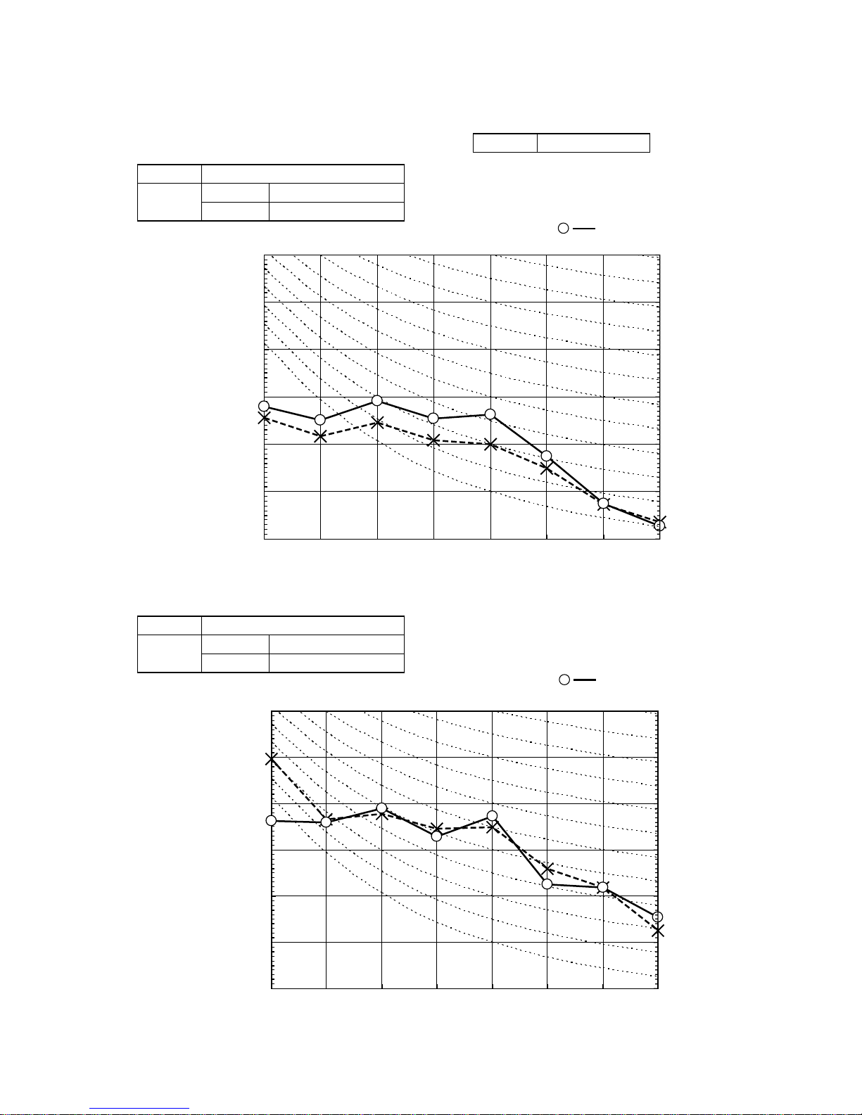
Model SRK25ZJ-S
Cool Mode
Air flow
outdoor
air temp.
indoor air temp
16˚CDB 18˚CDB 20˚CDB 22˚CDB 24˚CDB
Hi
10.6
(m
3
/min)
-15˚CWB 1.97 1.93 1.88 1.84 1.80
-10˚CWB 2.23 2.19 2.16 2.10 2.06
-5˚CWB 2.41 2.38 2.33 2.30 2.27
0˚CWB 2.53 2.49 2.45 2.42 2.38
5˚CWB 3.22 3.19 3.17 3.10 3.06
6˚CWB 3.27 3.24 3.20 3.16 3.12
10˚CWB 3.48 3.45 3.42 3.38 3.34
15˚CWB 3.79 3.75 3.73 3.69 3.65
20˚CWB 4.07 4.04 4.02 3.97 3.94
Heat Mode
Air flow
outdoor
air temp.
indoor air temp
16˚CDB 18˚CDB 20˚CDB 22˚CDB 24˚CDB
Hi
12.8
(m
3
/min)
-15˚CWB 2.46 2.41 2.35 2.30 2.25
-10˚CWB 2.79 2.74 2.70 2.63 2.58
-5˚CWB 3.02 2.97 2.91 2.88 2.83
0˚CWB 3.16 3.12 3.06 3.02 2.98
5˚CWB 4.03 3.98 3.96 3.88 3.83
6˚CWB 4.09 4.04 4.00 3.95 3.90
10˚CWB 4.35 4.31 4.28 4.22 4.18
15˚CWB 4.73 4.69 4.66 4.61 4.56
20˚CWB 5.09 5.05 5.02 4.96 4.92
Heat Mode
Air flow
Outdoor
air temp.
Indoor air temp
21˚CDB 23˚CDB 26˚CDB 27˚CDB 28˚CDB 31˚CDB 33˚CDB
14˚CWB 16˚CWB 18˚CWB 19˚CWB 20˚CWB 22˚CWB 24˚CWB
TC SHC TC SHC TC SHC TC SHC TC SHC TC SHC TC SHC
Hi
10.1
(m
3
/min)
10
3.94 3.00 4.13 2.95 4.28 3.04 4.35 3.00 4.43 2.97 4.56 3.04 4.68 2.94
12 3.87 2.97 4.06 2.92 4.22 3.02 4.29 2.98 4.37 2.94 4.51 3.02 4.63 2.93
14 3.80 2.93 3.99 2.88 4.16 2.99 4.24 2.96 4.31 2.91 4.46 3.00 4.59 2.91
16 3.72 2.89 3.91 2.85 4.09 2.96 4.18 2.93 4.25 2.89 4.40 2.98 4.54 2.89
18 3.65 2.85 3.84 2.81 4.03 2.93 4.11 2.90 4.19 2.87 4.35 2.96 4.49 2.88
20 3.57 2.81 3.76 2.77 3.96 2.90 4.05 2.87 4.13 2.84 4.29 2.94 4.43 2.85
22 3.49 2.77 3.68 2.73 3.89 2.86 3.98 2.83 4.06 2.80 4.23 2.92 4.38 2.84
24 3.40 2.72 3.59 2.69 3.81 2.83 3.91 2.81 3.99 2.78 4.17 2.89 4.32 2.81
26 3.32 2.68 3.51 2.65 3.74 2.80 3.84 2.78 3.92 2.75 4.11 2.86 4.26 2.80
28 3.23 2.63 3.42 2.61 3.66 2.77 3.77 2.76 3.85 2.72 4.04 2.84 4.20 2.77
30 3.14 2.59 3.33 2.57 3.58 2.74 3.70 2.72 3.78 2.70 3.98 2.82 4.13 2.75
32 3.05 2.54 3.24 2.52 3.50 2.70 3.62 2.69 3.70 2.66 3.91 2.79 4.06 2.73
34 2.95 2.50 3.14 2.48 3.41 2.66 3.54 2.66 3.62 2.63 3.84 2.77 4.00 2.69
35 2.91 2.48 3.10 2.46 3.37 2.65 3.50 2.64 3.58 2.62 3.80 2.75 3.96 2.68
36 2.86 2.46 3.05 2.44 3.33 2.63 3.46 2.63 3.54 2.60 3.76 2.72 3.92 2.67
38 2.76 2.41 2.95 2.40 3.24 2.59 3.38 2.59 3.46 2.57 3.69 2.70 3.85 2.65
39 2.71 2.39 2.90 2.37 3.20 2.57 3.33 2.58 3.42 2.56 3.65 2.69 3.81 2.64
Model SRK35ZJ-S
Cool Mode
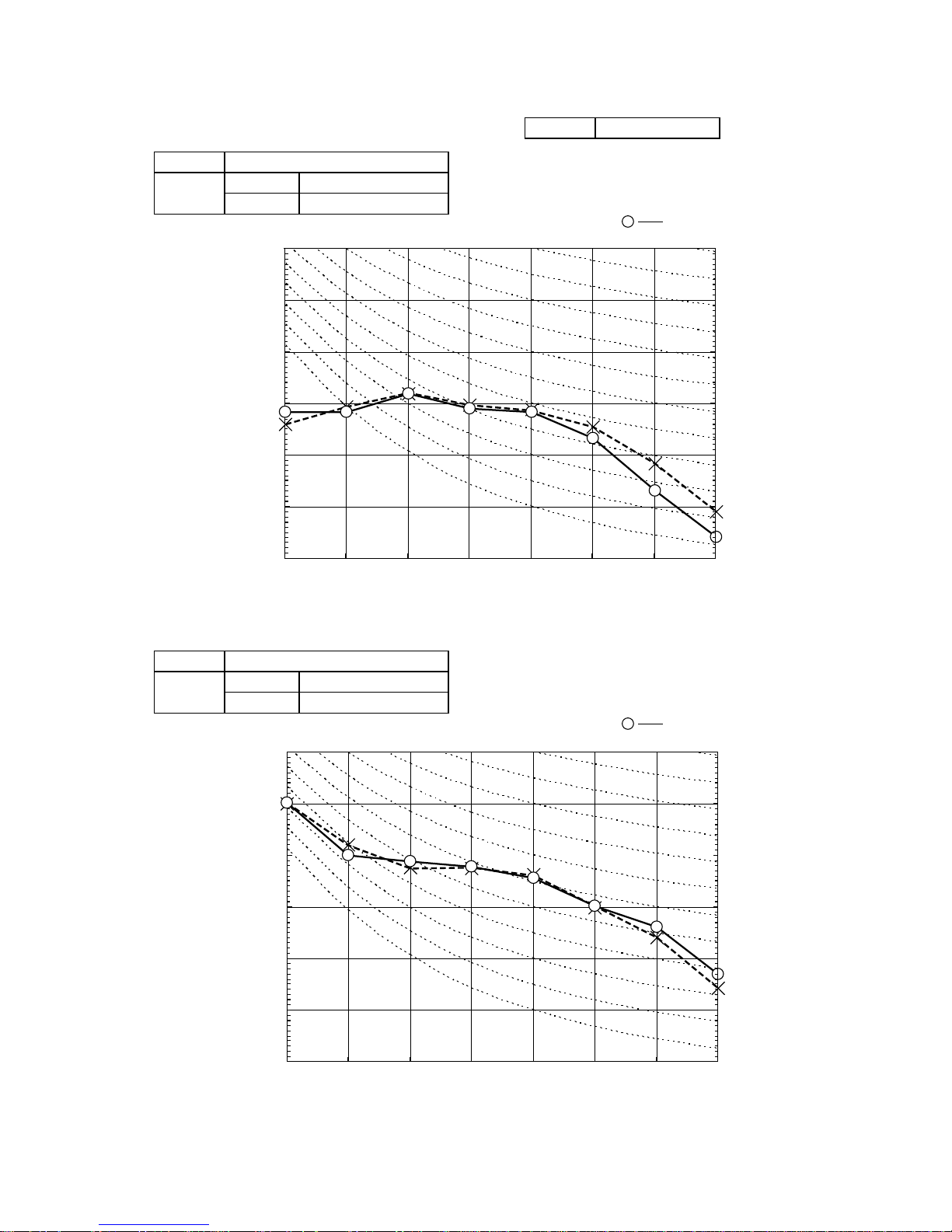
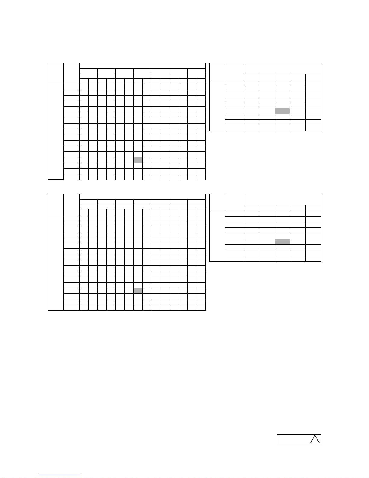
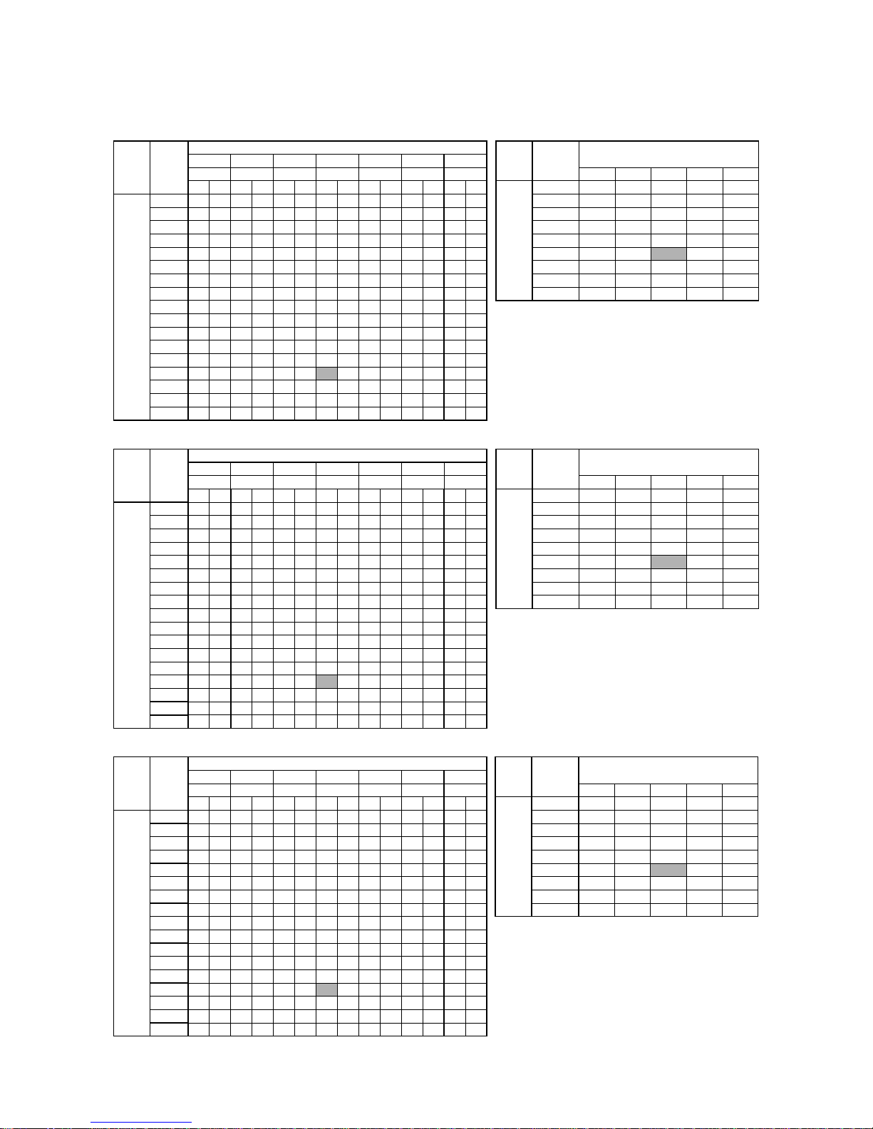
7. CAPACITY TABLES
a
ISC09106
-
27
-
'10 • SRK-T-098
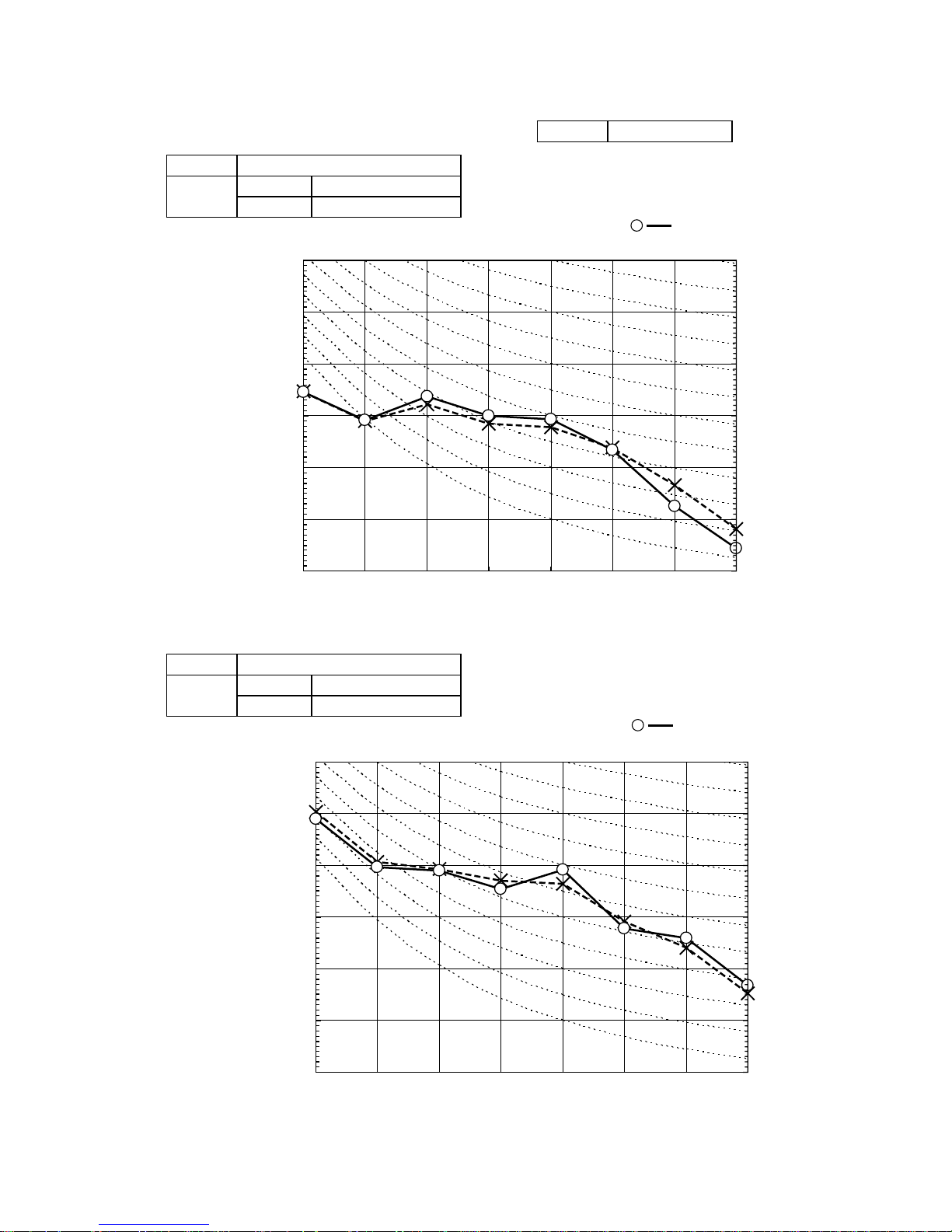
Heat Mode
Model SRK20ZJX-S
Cool Mode
Model SRK25ZJX-S
Cool Mode
Heat Mode
Air flow
Outdoor
air temp.
Indoor air temp
21˚CDB 23˚CDB 26˚CDB 27˚CDB 28˚CDB 31˚CDB 33˚CDB
14˚CWB 16˚CWB 18˚CWB 19˚CWB 20˚CWB 22˚CWB 24˚CWB
TC SHC TC SHC TC SHC TC SHC TC SHC TC SHC TC SHC
Hi
11.5
(m
3
/min)
10 2.25 2.14 2.36 2.11 2.45 2.24 2.49 2.21 2.53 2.19 2.60 2.30 2.67 2.24
12 2.21 2.10 2.32 2.09 2.41 2.22 2.45 2.20 2.50 2.18 2.58 2.29 2.65 2.24
14 2.17 2.06 2.28 2.07 2.38 2.21 2.42 2.19 2.47 2.17 2.55 2.28 2.62 2.23
16 2.13 2.02 2.24 2.05 2.34 2.19 2.39 2.18 2.43 2.15 2.52 2.27 2.59 2.22
18 2.08 1.98 2.19 2.03 2.30 2.17 2.35 2.16 2.40 2.14 2.49 2.26 2.56 2.21
20 2.04 1.94 2.15 2.02 2.26 2.15 2.31 2.15 2.36 2.13 2.45 2.25 2.53 2.20
22 1.99 1.89 2.10 2.00 2.22 2.11 2.28 2.13 2.32 2.12 2.42 2.23 2.50 2.19
24 1.94 1.85 2.05 1.95 2.18 2.07 2.24 2.11 2.28 2.10 2.38 2.23 2.47 2.18
26 1.90 1.80 2.01 1.91 2.14 2.03 2.20 2.09 2.24 2.08 2.35 2.21 2.43 2.18
28 1.85 1.75 1.96 1.86 2.09 1.99 2.15 2.05 2.20 2.05 2.31 2.19 2.40 2.16
30 1.79 1.70 1.90 1.81 2.05 1.94 2.11 2.01 2.16 2.04 2.27 2.16 2.36 2.15
32 1.74 1.65 1.85 1.76 2.00 1.90 2.07 1.96 2.12 2.01 2.23 2.12 2.32 2.14
34 1.69 1.60 1.80 1.71 1.95 1.85 2.02 1.92 2.07 1.97 2.19 2.08 2.28 2.13
35 1.66 1.58 1.77 1.68 1.93 1.83 2.00 1.90 2.05 1.94 2.17 2.06 2.26 2.12
36 1.63 1.55 1.74 1.65 1.90 1.81 1.98 1.88 2.02 1.92 2.15 2.04 2.24 2.11
38 1.58 1.50 1.68 1.60 1.85 1.76 1.93 1.83 1.98 1.88 2.11 2.00 2.20 2.09
39 1.55 1.47 1.66 1.57 1.83 1.74 1.91 1.81 1.95 1.85 2.08 1.98 2.18 2.07
Air flow
outdoor
air temp.
indoor air temp
16˚CDB 18˚CDB 20˚CDB 22˚CDB 24˚CDB
Hi
12.0
(m
3
/min)
-15˚CWB 1.54 1.51 1.47 1.44 1.41
-10˚CWB 1.74 1.71 1.69 1.64 1.61
-5˚CWB 1.89 1.86 1.82 1.80 1.77
0˚CWB 1.98 1.95 1.91 1.89 1.86
5˚CWB 2.52 2.49 2.48 2.43 2.39
6˚CWB 2.56 2.53 2.50 2.47 2.44
10˚CWB 2.72 2.69 2.68 2.64 2.61
15˚CWB 2.96 2.93 2.91 2.88 2.85
20˚CWB 3.18 3.15 3.14 3.10 3.08
Air flow
Outdoor
air temp.
Indoor air temp
21˚CDB 23˚CDB 26˚CDB 27˚CDB 28˚CDB 31˚CDB 33˚CDB
14˚CWB 16˚CWB 18˚CWB 19˚CWB 20˚CWB 22˚CWB 24˚CWB
TC SHC TC SHC TC SHC TC SHC TC SHC TC SHC TC SHC
Hi
12.5
(m
3
/min)
10 2.87 2.69 3.01 2.65 3.12 2.80 3.17 2.77 3.23 2.74 3.32 2.88 3.41 2.81
12 2.82 2.67 2.96 2.63 3.07 2.78 3.13 2.75 3.19 2.73 3.28 2.86 3.38 2.80
14 2.77 2.63 2.90 2.61 3.03 2.76 3.09 2.74 3.14 2.69 3.25 2.85 3.34 2.79
16 2.71 2.58 2.85 2.58 2.98 2.74 3.04 2.70 3.10 2.68 3.21 2.84 3.31 2.78
18 2.66 2.52 2.80 2.56 2.93 2.71 3.00 2.69 3.05 2.66 3.17 2.82 3.27 2.77
20 2.60 2.47 2.74 2.54 2.88 2.69 2.95 2.67 3.01 2.65 3.13 2.81 3.23 2.75
22 2.54 2.41 2.68 2.51 2.83 2.67 2.90 2.65 2.96 2.63 3.08 2.80 3.19 2.74
24 2.48 2.36 2.62 2.48 2.78 2.64 2.85 2.64 2.91 2.61 3.04 2.78 3.15 2.72
26 2.42 2.30 2.56 2.43 2.72 2.59 2.80 2.62 2.86 2.60 2.99 2.76 3.10 2.71
28 2.35 2.24 2.49 2.37 2.67 2.53 2.75 2.60 2.81 2.58 2.95 2.75 3.06 2.70
30 2.29 2.17 2.43 2.31 2.61 2.48 2.69 2.56 2.75 2.56 2.90 2.74 3.01 2.69
32 2.22 2.11 2.36 2.24 2.55 2.42 2.64 2.50 2.70 2.54 2.85 2.70 2.96 2.67
34 2.15 2.04 2.29 2.18 2.49 2.36 2.58 2.45 2.64 2.51 2.79 2.65 2.91 2.65
35 2.12 2.01 2.26 2.14 2.46 2.33 2.55 2.42 2.61 2.48 2.77 2.63 2.89 2.65
36 2.08 1.98 2.22 2.11 2.43 2.30 2.52 2.39 2.58 2.45 2.74 2.60 2.86 2.64
38 2.01 1.91 2.15 2.04 2.36 2.24 2.46 2.34 2.52 2.39 2.69 2.55 2.81 2.60
39 1.97 1.88 2.11 2.01 2.33 2.21 2.43 2.31 2.49 2.36 2.66 2.52 2.78 2.59
Air flow
outdoor
air temp.
indoor air temp
16˚CDB 18˚CDB 20˚CDB 22˚CDB 24˚CDB
Hi
13.0
(m
3
/min)
-15˚CWB 1.93 1.88 1.84 1.80 1.76
-10˚CWB 2.18 2.14 2.11 2.06 2.02
-5˚CWB 2.36 2.33 2.28 2.25 2.22
0˚CWB 2.47 2.44 2.40 2.37 2.33
5˚CWB 3.15 3.12 3.10 3.04 2.99
6˚CWB 3.20 3.17 3.13 3.09 3.05
10˚CWB 3.40 3.37 3.35 3.30 3.27
15˚CWB 3.70 3.67 3.65 3.61 3.57
20˚CWB 3.98 3.95 3.93 3.88 3.85
Heat Mode
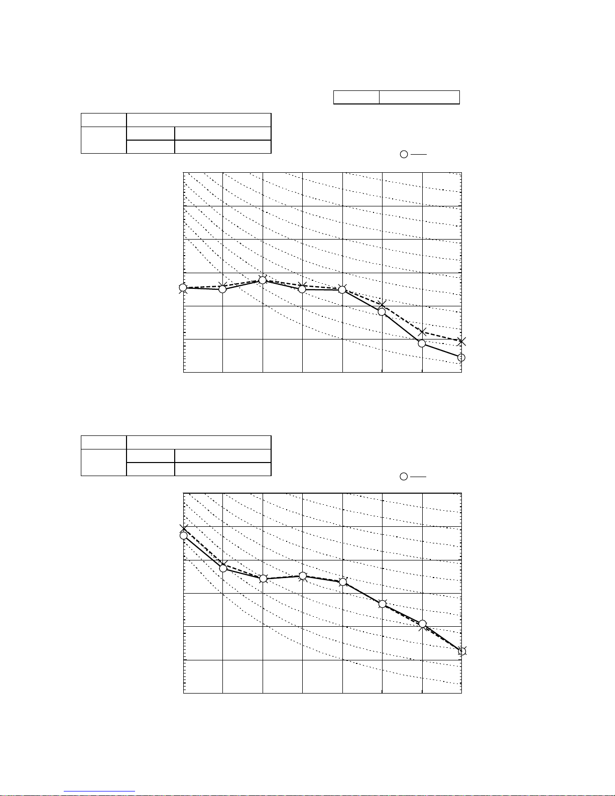
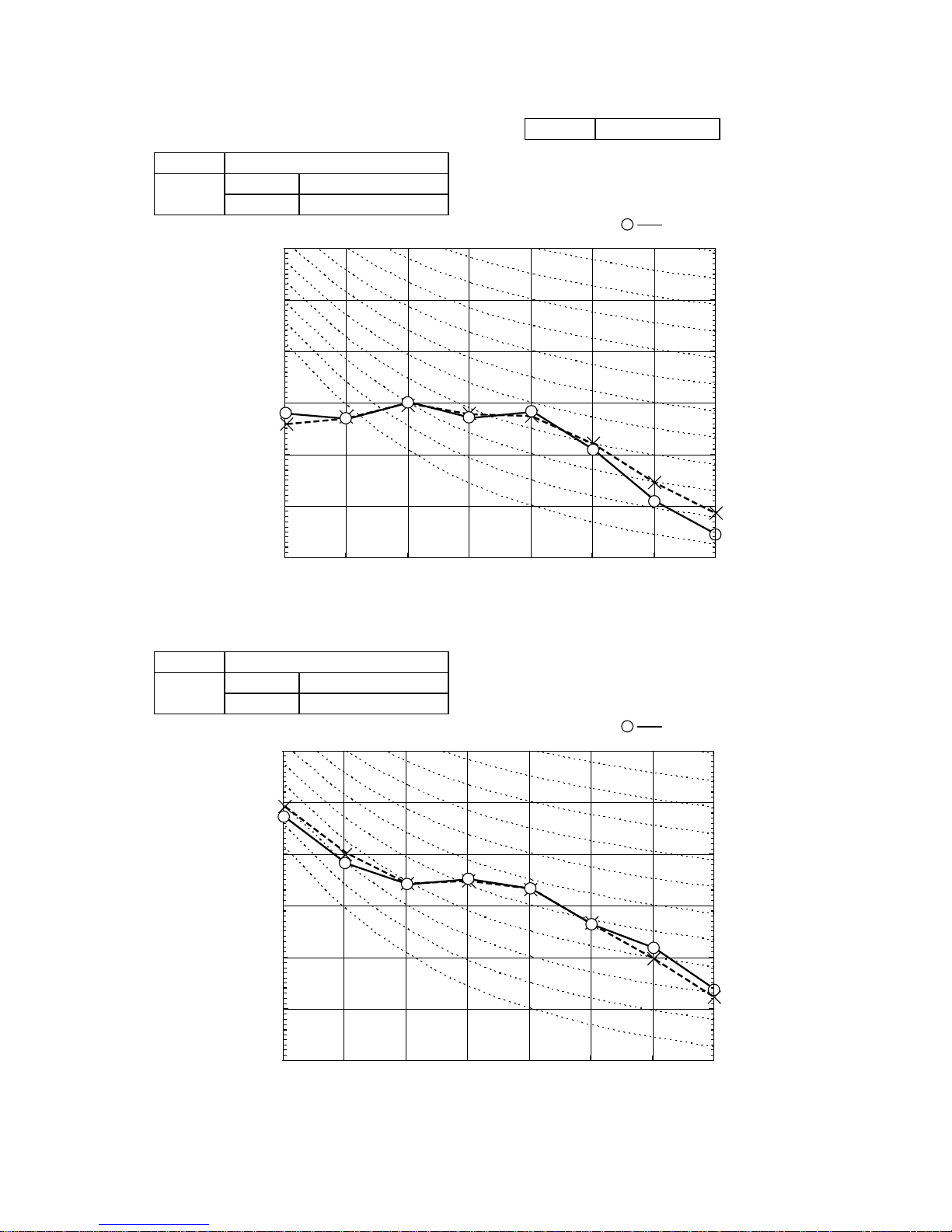
Model SRK35ZJX-S
Cool Mode
Air flow
Outdoor
air temp.
Indoor air temp
21˚CDB 23˚CDB 26˚CDB 27˚CDB 28˚CDB 31˚CDB 33˚CDB
14˚CWB 16˚CWB 18˚CWB 19˚CWB 20˚CWB 22˚CWB 24˚CWB
TC SHC TC SHC TC SHC TC SHC TC SHC TC SHC TC SHC
Hi
13.5
(m
3
/min)
10 3.94 3.47 4.13 3.42 4.28 3.59 4.35 3.55 4.43 3.51 4.56 3.66 4.68 3.55
12 3.87 3.44 4.06 3.39 4.22 3.56 4.29 3.53 4.37 3.49 4.51 3.65 4.63 3.53
14 3.80 3.40 3.99 3.36 4.16 3.54 4.24 3.50 4.31 3.47 4.46 3.61 4.59 3.52
16 3.72 3.37 3.91 3.32 4.09 3.51 4.18 3.48 4.25 3.44 4.40 3.59 4.54 3.50
18 3.65 3.33 3.84 3.29 4.03 3.48 4.11 3.45 4.19 3.42 4.35 3.57 4.49 3.49
20 3.57 3.30 3.76 3.25 3.96 3.46 4.05 3.43 4.13 3.39 4.29 3.55 4.43 3.47
22 3.49 3.26 3.68 3.22 3.89 3.43 3.98 3.40 4.06 3.37 4.23 3.53 4.38 3.45
24 3.40 3.22 3.59 3.19 3.81 3.40 3.91 3.38 3.99 3.35 4.17 3.51 4.32 3.44
26 3.32 3.15 3.51 3.14 3.74 3.37 3.84 3.35 3.92 3.32 4.11 3.49 4.26 3.42
28 3.23 3.07 3.42 3.11 3.66 3.34 3.77 3.32 3.85 3.30 4.04 3.47 4.20 3.40
30 3.14 2.98 3.33 3.07 3.58 3.31 3.70 3.29 3.78 3.26 3.98 3.45 4.13 3.38
32 3.05 2.90 3.24 3.03 3.50 3.27 3.62 3.26 3.70 3.24 3.91 3.43 4.06 3.36
34 2.95 2.81 3.14 2.99 3.41 3.24 3.54 3.23 3.62 3.21 3.84 3.40 4.00 3.34
35 2.91 2.76 3.10 2.94 3.37 3.20 3.50 3.22 3.58 3.20 3.80 3.39 3.96 3.33
36 2.86 2.72 3.05 2.90 3.33 3.16 3.46 3.20 3.54 3.18 3.76 3.38 3.92 3.32
38 2.76 2.62 2.95 2.80 3.24 3.08 3.38 3.18 3.46 3.15 3.69 3.36 3.85 3.30
39 2.71 2.57 2.90 2.75 3.20 3.04 3.33 3.16 3.42 3.14 3.65 3.34 3.81 3.29
Air flow
outdoor
air temp.
indoor air temp
16˚CDB 18˚CDB 20˚CDB 22˚CDB 24˚CDB
Hi
14.0
(m
3
/min)
-15˚CWB 2.65 2.59 2.53 2.48 2.42
-10˚CWB 2.99 2.94 2.90 2.83 2.77
-5˚CWB 3.24 3.20 3.13 3.10 3.05
0˚CWB 3.40 3.35 3.29 3.25 3.20
5˚CWB 4.33 4.28 4.26 4.17 4.11
6˚CWB 4.40 4.35 4.30 4.25 4.19
10˚CWB 4.68 4.63 4.60 4.54 4.49
15˚CWB 5.09 5.04 5.01 4.95 4.91
20˚CWB 5.47 5.42 5.40 5.34 5.29
-
28
-
'10 • SRK-T-098
8. APPLICATION DATA
8.1 Installation of indoor unit
(1) Models SRK25ZJ-S, 35ZJ-S
'09•SRK-DB-087D
SAFETY PRECAUTIONS
WARNING
• We recommend you to read this “SAFETY PRECAUTIONS” carefully before the
installation work in order to gain full advantage of the functions of the unit and
to avoid malfunction due to mishandling.
• The precautions described below are divided into
and . The matters with possibilities leading to
serious consequences such as death or serious personal injury due to
erroneous handling are listed in the and the matters with
possibilities leading to personal injury or damage of the unit due to erroneous
handling including probability leading to serious consequences in some cases
are listed in . These are very important precautions for safety.
Be sure to observe all of them without fail.
• Be sure to confirm no anomaly on the equipment by commissioning after
completed installation and explain the operating methods as well as the
maintenance methods of this equipment to the user according to the owner’s
manual.
• Keep the installation manual together with owner’s manual at a place where
any user can read at any time. Moreover if necessary, ask to hand them to a
new user.
• For installing qualified personnel, take precautions in respect to themselves by
using suitable protective clothing, groves, etc., and then perform the
installation works.
• Please pay attention not to fall down the tools, etc. when installing the unit at
the high position.
• If unusual noise can be heard during operation, consult the dealer.
• Symbols which appear frequently in the text have the following meaning:
• This instruction manual illustrates the method of installing an indoor
unit.
• For outdoor unit installation and refrigerant piping, please refer to
page 36.
• A wired remote control unit is supplied separately as an optional part.
• When install the unit, be sure to check whether the selection of
installation place, power supply specifications, usage limitation (piping
length, height differences between indoor and outdoor units, power
supply voltage and etc.) and installation spaces.
Strictly prohibited
Observe instructions
with great care
Provide proper
earthing
CAUTIONWARNING
CAUTION
WARNING
• Installation must be carried out by the qualified installer.
• Install the system in full accordance with the instruction manual.
Incorrect installation may cause bursts, personal injury, water leaks, electric
shocks and fire.
• Be sure to use only for household and residence.
If this appliance is installed in inferior environment such as machine shop
and etc., it can cause malfunction.
• Use the original accessories and the specified components for
installation.
If parts other than those prescribed by us are used, It may cause water
leaks, electric shocks, fire and personal injury.
• Install the unit in a location with good support.
Unsuitable installation locations can cause the unit to fall and cause
material damage and personal injury.
• Ventilate the working area well in the event of refrigerant leakage
during installation.
If the refrigerant comes into contact with naked flames, poisonous gas is
produced.
• When installing in small rooms, take prevention measures not to
exceed the density limit of refrigerant in the event of leakage.
Consult the expert about prevention measures. If the density of refrigerant
exceeds the limit in the event of leakage, lack of oxygen can occur, which
can cause serious accidents.
• After completed installation, check that no refrigerant leaks from
the system.
If refrigerant leaks into the room and comes into contact with an oven or
other hot surface, poisonous gas is produced.
• Use the prescribed pipes, flare nuts and tools for R410A.
Using existing parts (for R22 or R407C) can cause the unit failure and
serious accidents due to burst of the refrigerant circuit.
• Tighten the flare nut by torque wrench with specified method.
If the flare nut were tightened with excess torque, this may cause burst and
refrigerant leakage after a long period.
• The electrical installation must be carried out by the qualified
electrician in accordance with “the norm for electrical work” and
“national wiring regulation”, and the system must be connected to
the dedicated circuit.
Power supply with insufficient capacity and incorrect function done by
improper work can cause electric shocks and fire.
• Be sure to shut off the power before starting electrical work.
Failure to shut off the power can cause electric shocks, unit failure or
incorrect function of equipment.
• Be sure to use the cables conformed to safety standard and cable
ampacity for power distribution work.
Unconformable cables can cause electric leak, anomalous heat production
or fire.
• This appliance must be connected to main power supply by means
of a circuit breaker or switch (fuse:16A) with a contact separation of
at least 3mm.
• When plugging this appliance, a plug conforming to the norm
IEC60884-1 must be used.
• Use the prescribed cables for electrical connection, tighten the
cables securely in terminal block and relieve the cables correctly to
prevent overloading the terminal blocks.
Loose connections or cable mountings can cause anomalous heat
production or fire.
• Arrange the wiring in the control box so that it cannot be pushed up
further into the box. Install the service panel correctly.
Incorrect installation may result in overheating and fire.
• Be sure to switch off the power supply in the event of installation,
inspection or servicing.
If the power supply is not shut off, there is a risk of electric shocks, unit
failure or personal injury due to the unexpected start of fan.
CAUTION
• Use the circuit breaker with sufficient breaking capacity.
If the breaker does not have sufficient breaking capacity, it can cause the
unit malfunction and fire.
• Earth leakage breaker must be installed.
If the earth leakage breaker is not installed, it can cause electric shocks.
• Install isolator or disconnect switch on the power supply wiring in
accordance with the local codes and regulations.
• Be sure to install indoor unit properly according to the instruction
manual in order to run off the drainage smoothly.
Improper installation of indoor unit can cause dropping water into the room
and damaging personal property.
• Install the drainage pipe to run off drainage securely according to
the installation manual.
Incorrect installation of the drainage pipe can cause dropping water into the
room and damaging personal property.
• Be sure to install the drainage pipe with descending slope of 1/100
or more, and not to make traps and air-bleedings.
Check if the drainage runs off securely during commissioning and ensure
the space for inspection and maintenance.
• Secure a space for installation, inspection and maintenance
specified in the manual.
Insufficient space can result in accident such as personal injury due to
falling from the installation place.
• For installation work, be careful not to get injured with the heat
exchanger, piping flare portion or screws etc.
• Be sure to insulate the refrigerant pipes so as not to condense the
ambient air moisture on them.
Insufficient insulation can cause condensation, which can lead to moisture
damage on the ceiling, floor, furniture and any other valuables.
• When perform the air conditioner operation (cooling or drying
operation) in which ventilator is installed in the room. In this case,
using the air conditioner in parallel with the ventilator, there is the
possibility that drain water may backflow in accordance with the
room lapse into the negative pressure status. Therefore, set up the
opening port such as incorporate the air into the room that may
appropriate to ventilation (For example; Open the door a little). In
addition, just as above, so set up the opening port if the room lapse
into negative pressure status due to register of the wind for the high
rise apartment etc.
• Do not install the unit in the locations listed below.
• Locations where carbon fiber, metal powder or any powder is floating.
• Locations where any substances that can affect the unit such as sulphide
gas, chloride gas, acid and alkaline can occur.
• Vehicles and ships.
• Locations where cosmetic or special sprays are often used.
• Locations with direct exposure of oil mist and steam such as kitchen and
machine plant.
• Locations where any machines which generate high frequency harmonics
are used.
• Locations with salty atmospheres such as coastlines.
• Locations with heavy snow (If installed, be sure to provide base flame and
snow hood mentioned in the manual).
• Locations where the unit is exposed to chimney smoke.
• Locations at high altitude (more than 1000m high).
• Locations with ammonic atmospheres.
• Locations where heat radiation from other heat source can affect the unit.
• Locations without good air circulation.
• Locations with any obstacles which can prevent inlet and outlet air of the
unit.
• Locations where short circuit of air can occur (in case of multiple units
installation).
• Locations where strong air blows against the air outlet of outdoor unit.
It can cause remarkable decrease in performance, corrosion and damage
of components, malfunction and fire.
• Do not install the indoor unit in the locations listed below (Be sure
to install the indoor unit according to the installation manual for
each model because each indoor unit has each limitation).
• Locations with any obstacles which can prevent inlet and outlet air of the
unit.
• Locations where vibration can be amplified due to insufficient strength of
structure.
• Locations where the infrared receiver is exposed to the direct sunlight or
the strong light beam (in case of the infrared specification unit).
• Locations where an equipment affected by high harmonics is placed (TV
set or radio receiver is placed within 1m).
• Locations where drainage cannot run off safely.
It can affect performance or function and etc.
• Do not install the unit near the location where leakage of
combustible gases can occur.
If leaked gases accumulate around the unit, it can cause fire.
• Do not install the unit where corrosive gas (such as sulfurous acid
gas etc.) or combustible gas (such as thinner and petroleum gases)
can accumulate or collect, or where volatile combustible
substances are handled.
Corrosive gas can cause corrosion of heat exchanger, breakage of plastic
parts and etc. And combustible gas can cause fire.
• Do not use the indoor unit at the place where water splashes may
occur such as in laundries.
Since the indoor unit is not waterproof, it can cause electric shocks and
fire.
• Do not install nor use the system close to the equipment that
generates electromagnetic fields or high frequency harmonics.
Equipment such as inverters, standby generators, medical high frequency
equipments and telecommunication equipments can affect the system, and
cause malfunctions and breakdowns. The system can also affect medical
equipment and telecommunication equipment, and obstruct its function or
cause jamming.
• Do not place any variables which will be damaged by getting wet
under the indoor unit.
When the relative humidity is higher than 80% or drainage pipe is clogged,
condensation or drainage water can drop and it can cause the damage of
valuables.
• Do not install the remote control at the direct sunlight.
It can cause malfunction or deformation of the remote control.
• Do not use the unit for special purposes such as storing foods,
cooling precision instruments and preservation of animals, plants or
art.
It can cause the damage of the items.
• Do not use any materials other than a fuse with the correct rating in
the location where fuses are to be used.
Connecting the circuit with copper wire or other metal thread can cause
unit failure and fire.
• Do not touch any buttons with wet hands.
It can cause electric shocks.
• Do not touch any refrigerant pipes with your hands when the
system is in operation.
During operation the refrigerant pipes become extremely hot or extremely
cold depending the operating condition, and it can cause burn injury or
frost injury.
• Carry out the electrical work for ground lead with care.
Do not connect the ground lead to the gas line, water line, lightning conductor or telephone line’s ground lead. Incorrect grounding can cause unit faults
such as electric shocks due to short-circuiting.
• Do not put the drainage pipe directly into drainage channels where
poisonous gases such as sulphide gas can occur.
Poisonous gases will flow into the room through drainage pipe and
seriously affect the user’s health and safety.
• Ensure that no air enters in the refrigerant circuit when the unit is
installed and removed.
If air enters in the refrigerant circuit, the pressure in the refrigerant circuit
becomes too high, which can cause burst and personal injury.
• Do not processing, splice the power cord, or share a socket with
other power plugs.
This may cause fire or electric shock due to defecting contact, defecting
insulation and over-current etc.
• Do not bundling, winding or processing for the power cord. Or, do
not deforming the power plug due to tread it.
This may cause fire or heating.
• Do not vent R410A into the atmosphere : R410A is a fluorinated
greenhouse gas, covered by the Kyoto Protocol with Global
Warming Potential (GWP)=1975.
• Do not run the unit with removed panels or protections.
Touching rotating equipments, hot surfaces or high voltage parts can cause
personal injury due to entrapment, burn or electric shocks.
• Do not perform any change of protective device itself or its setup
condition.
The forced operation by short-circuiting protective device of pressure
switch and temperature controller or the use of non specified component
can cause fire or burst.
WARNING
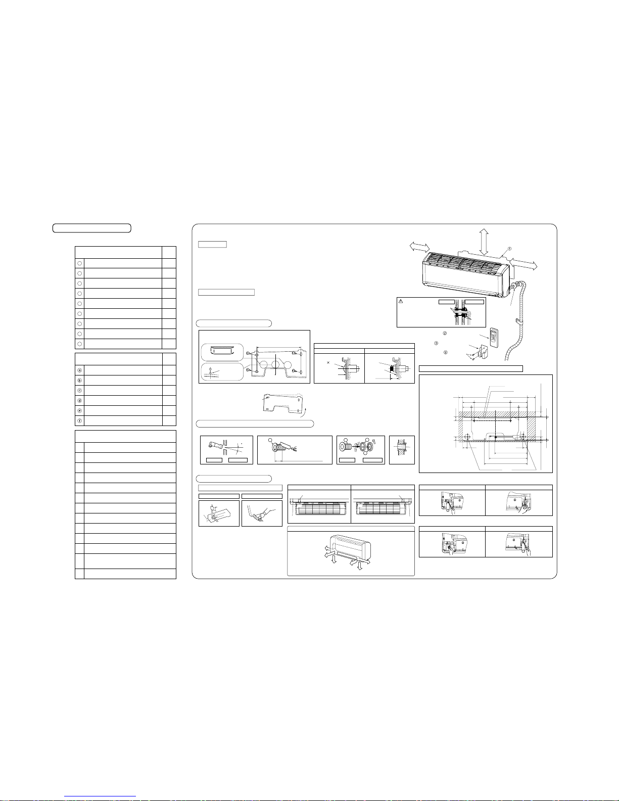
-
29
-
'10 • SRK-T-098
'09•SRK-DB-087D
Necessary tools for the installation work
1
2
3
4
5
6
7
8
9
10
11
12
13
1
1
1
1
1
1
Q’ty
Option parts
Sealing plate
Sleeve
Inclination plate
Putty
Drain hose (extension hose)
Piping cover
(for insulation of connection piping)
Plus headed driver
Knife
Saw
Tape measure
Hammer
Spanner wrench
Torque wrench
Hole core drill (65mm in diameter)
Wrench key (Hexagon) [4m/m]
Flaring tool set
Gas leak detector
Pipe bender
Gauge for projection adjustment
Used when flare is made by using
conventional flare tool
( )
( )
14.0 ~ 61.0N·m
(1.4 ~ 6.1kgf·m)
(
Designed specifically
for R410A
)
Piping in the left direction
Piping in the right rear directionPiping in the left rear direction
Piping in the right direction
INSTALLATION SPACE (INDOOR UNIT)
(FRONT VIEW)
Piping is possible in the rear, left, left rear, left downward, right or downward direction.
Right
Rear
Downward
Left
rear
Left downward
Left
Wireless remote control
Remote control holder
Wood screws
٤ Before installation check that the power supply matches the air conditioner.
Indoor unit
Relation between setting plate and indoor unit
Installing the support of piping
(Install at location that meets the following conditions, after getting approval from the customer)
٤ Where there is no obstructions to the air flow and where the cooled and heated air can be evenly distributed.
٤ A solid place where the unit or the wall will not vibrate.
٤ A place where there will be enough space for servicing. (Where space mentioned below can be secured)
٤ Where wiring and the piping work will be easy to conduct.
٤ The place where receiving part is not exposed to the direct rays of the sun or the strong rays of the street lighting.
٤ A place where it can be easily drained.
٤ A place separated at least 1m away from the television or the radio. (To prevent interference to images and sounds.)
٤ Places where this unit is not affected by the high frequency equipment or electric equipment.
٤
Avoid installing this unit in place where there is much oil mist.
٤ Places where there is no electric equipment or household under the installing unit.
Wireless remote control
In case of piping in the right rear direction
٤
A place where the air conditioner can be received the signal surely during operating the wireless remote control.
٤ Places where there is no affected by the TV and radio etc.
٤ Do not place where exposed to direct sunlight or near heat devices such as a stove.
Sufficient care must be taken not to damage
the panel when connecting pipes.
[Top view]
When drilling the wall that contains a metal lath, wire lath or metal plate, be sure to use pipe hole sleeve sold separately.
• Matters of special notice when piping from left or central/rear of the unit.
Left-hand-side piping Right-hand-side piping
Installation of Installation board
Drilling of holes and fixture of sleeve (Option parts)
Level position (2 locations)
Mating mark for
level surface
Fixing on concrete wall
Use of nut anchor Use of bolt anchor
Shaping of pipings Taping of the exterior
Pipings
Drain hose
Top
Nut
(M6)
Mounting
board
Mounting
board
Max.10
Thickness of the wall + 1.5cm
5
ø65
Indoor side Outdoor side
Indoor side Outdoor side Installed state
Turn to
tighten
b
b
c
a
Bolt
(M6 12)
5 cm minimum
from the wall
10 cm minimum
from the wall
Installation board
Sleeve
(sold separately)
6.5 cm minimum from the ceiling
٤ In case of rear piping draw out, cut off the lower
and the right side portions of the sleeve collar.
٤ Drill a hole with whole core drill.
٤ Hold the bottom of the
piping and fix direction
before stretching it and
shaping it.
٤ Tape only the portion
that goes through the
wall.
٤ Always tape the wiring
with the piping.
[Drain hose changing procedures]
1. Remove the drain hose 2. Remove the drain cap.
٤ Remove it with hand or pliers.٤ Remove the screw and drain hose,
making it rotate.
3. Insert the drain cap. 4. Connect the drain hose.
٤ Insert the drain cap which was removed
at procedure “2” securely using a
hexagonal wrench etc.
Note: Be careful that If it is not Inserted
securely, water leakage may occur.
٤ Insert the drain hose securely, making
rotate. And install the screw.
Note: Be careful that If it is not Inserted
securely, water leakage may
occur.
٤ Adjustment of the installation board in the horizontal direction is to
be conducted with four screws in a temporary tightened state.
٤ Adjust so the board will be
level by turning the board
with the standard hole as
the center.
450
Look for the inside wall structures (Intermediats support or pillar
and firmly install the unit after level surface has been checked.)
Standard
hole
Piping for Liquid (20 to 50 type) : ø6.35
Piping for Gas (20 to 35 type) : ø9.52
(50 type) : ø12.7
Completely seal the hole on
the wall with putty. Otherwise,
furniture, or other, may be
wetted by leaked water or
dewing.
putty
putty
1
1
1
5
2
2
2
2
1
Q’ty
Standard accessories (Installation kit)
Accessories for indoor unit
Installation board
(Attached to the rear of the indoor unit)
Wireless remote control
Remote control holder
Battery [R03 (AAA, Micro) 1.5V]
Air-cleaning filters
Filter holders
(Attached to the front panel of indoor unit)
Insulation (#486 50 x 100 t3)
Tapping screws
(for installation board ø4 X 25mm)
Wood screws
(for remote control switch holder ø3.5 X 16mm)
1
2
3
4
5
6
7
8
9
( )
Designed specifically
for R410A
Space for service Space for service
Indoor unit
Installation board
Piping hole (ø65)
Drain hose (ø16)
Piping for Liquid
Piping for Gas
Piping hole (ø65)
Space for service
48.947
65
139 450 209
106.5 585 106.5
50 100
7.2 7.7279.1
4715 Space for service
55
531.8
471.6
403.6
55
Indoor side Outdoor side
 Loading...