

Mitsubishi Heavy Industries SRK20MA-S, SRC20MA-S, SRK25MA-S, SRC25MA-S, SRK35MA-S Technical Manual
...
- 1 -
Mitsubishi Heavy Industries Air Conditioners
Technical Manual
Manual Number: 2011 No. W2-01
Variable Frequency Wall Mounted Type
Room Air Conditioners
(Split system, heat pump type)
SRK20MA-S/SRC20MA-S
SRK25MA-S/SRC25MA-S
SRK35MA-S/SRC35MA-S
SRK50MA-S/SRC50MA-S
(R410A Refrigerant Used)
MITSUBISHI HEAVY INDUSTRIES, LTD.

- 2 -
Table of Contents
1. GENERAL INFORMATION…………..……………………….……1
1.1 Features……………………………………..……………………..…1
1.2 Model identification………………………………………………1
2 MODEL SELECTION…………………………………………………2
2.1 Model function..…………..…….……..………………………..……2
2.2 Range of usage……………………………………………..………6
2.3 Outline drawing……………………………..……………………..…6
2.4 Cooling cycle system diagram…….………………..…………...…8
2.5 Performance curve……………………………………………………9
3 ELECTRICAL WIRING DIAGRAM……………………………….10
4 NAME OF EACH PART AND ITS FUNCTION………….12
4.1 Name of each part………………………….......…………………....15
4.2 Emergency switch………………………….......…………………....15
4.3 Automatic restart……………..…………..………………………..15
4.4 Key lock………….…………..……..……………………………..15
4.5 CLEAN operation………………...……..…………………………..15
4.6 SLEEP operation……..……..…………………………….……..16
4.7 Timing off………...............................................................16
4.8 Timing on ...........................................................................17
4.9 Programmed timer........................................................................17
4.10 Current time setting.....................................................................18
4.11 HI POWER operation....................................................................18
4.12 JET operation.........................................................................18
4.13 POWER SAVE operation.................................................................19
4.14 Air direction adjustment..............................................................19
4.15 Area setting…......................................................................20
4.16 Installation location setting.............................................................20
4.17 Outline of automatic operation..................................................20

- 3 -
4.18 Outline of drying operation..................................................21
4.19 Outline of defrosting operation.................................................21
4.20 Outline of vertical and horizontal flaps control................................23
4.21 Outline of electronic expansion valve (EEV) control.....................24
4.22 Outline of compressor control.........................................24
4.23 Outline of outdoor fan control.........................................24
4.24 Outline of indoor fan control.........................................25
5 INSTALLATION................................................................................27
5.1 Selection of installation location.................................................29
5.2 Installation of indoor unit..................................................................30
5.3 Installation of outdoor unit...............................................................33
5.4 Pipe connection.................................................................................33
5.5 Precautions for wireless remote controller operation.........................35
5.6 Standard running data........................................................................36
6 MAINTENANCE................................................................................37
6.1 Electrical parts failure diagnosis method.....................................37
6.2 Servicing.............................................................................................58
7 SERVICING MANUAL.......................................................................59
8 MOUNT ASSEMBLY…………………………...........................74
8.1 Indoor unit.........................................................................................74
8.2 Outdoor unit......................................................................................90
- 1 -
1 GENERAL INFORMATION
1.1 Features
(1) Inverter
● Heating/cooling
The rotate speed of the compressor is changed steplessly in relation to varying load, and is linked
with the fans of indoor and outdoor units controlled by the changes of frequency, thus controls
the power.
● Allowing quick heating/cooling operation during start-up period.
The room temperature is kept constant through fine-tuned control after the machine is stabilized.
(2) Fuzzy control: According to the fuzzy control technology, the indoor temperature and humidity,
etc. are obtained through dynamic analysis to accurately regulate the rotate speeds
of the compressor and the fan to realize precise temperature control.
(3) Comfort: 3D air blowing, sleep mode, and other air blowing modes.
(4) Humanization: Room temperature displaying, key lock, concentrated/area air blowing.
(5) Life: Actual service life: over 20,000 hours; Working life: over 100,000 hours; On/off of relay:
over 50,000 times; Continuous on of LED: over 50,000 hours; On/off of emergency switch:
over 10,000 times.
(4) Self diagnosis function: We will continuously provide the best services for our customers through
devices judging abnormal operation, as follows:
Indoor indication
Error
RUN lamp
TIMER lamp
Temp.
indication
Indoor
unit
Sensors
Indoor heat exchanger sensor error
1 time/8 sec.
ON
06
Indoor inlet air (room temp.) sensor error
2 times/8 sec.
--
Others
Indoor fan motor error
6 times/8 sec.
16
Display communication error
--
--
00
Outdoor unit
Sensors
Outdoor temp. sensor error
Continuous
flashing
1 time/8 sec.
38
Outdoor heat exchanger (liquid pipe)
sensor error
2 times/8 sec.
37
Vent-pipe sensor error
4 times/8 sec.
39
Others
Power cut for current protection
ON
1 time/8 sec.
42
Failure of outdoor unit
2 times/8 sec.
59
Current safety
3 times/8 sec.
58
Failure of power module
4 times/8 sec.
51
Compressor over heat protection
5 times/8 sec.
36
Serial signal transmission error
6 times/8 sec.
05
Outdoor fan motor error
7 times/8 sec.
48
Cool room high pressure protection
control
Continuous
flashing
35
Controllable silicon voltage error
5 times/8 sec.
ON
47
Cooling circulation system protection
7 times/8 sec.
57
Locked-rotor/rotor lock
2 times/8 sec.
2 times/8 sec.
60
The air conditioner indicates the error of the indoor and outdoor sensors (thermistors) only when it is
in the stop mode. Error indication is removed after restart.
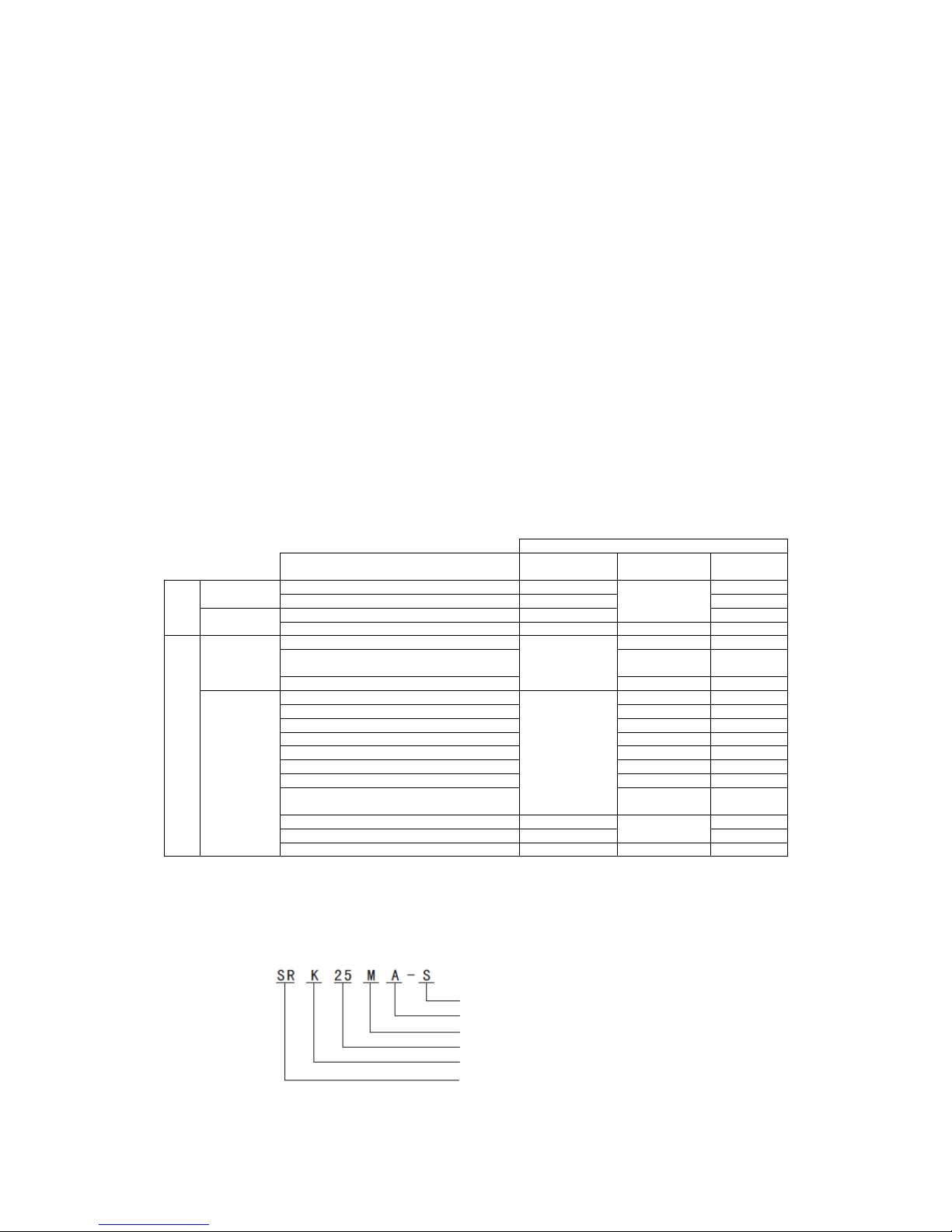
1.2 Model identification
For example:
R410A Refrigerant used
Master pattern change code
Master pattern
Capacity
Wall mounted type (C is the code for outdoor unit.)
Split type room air conditioner
- 2 -
2 MODEL SELECTION
2.1 Model function
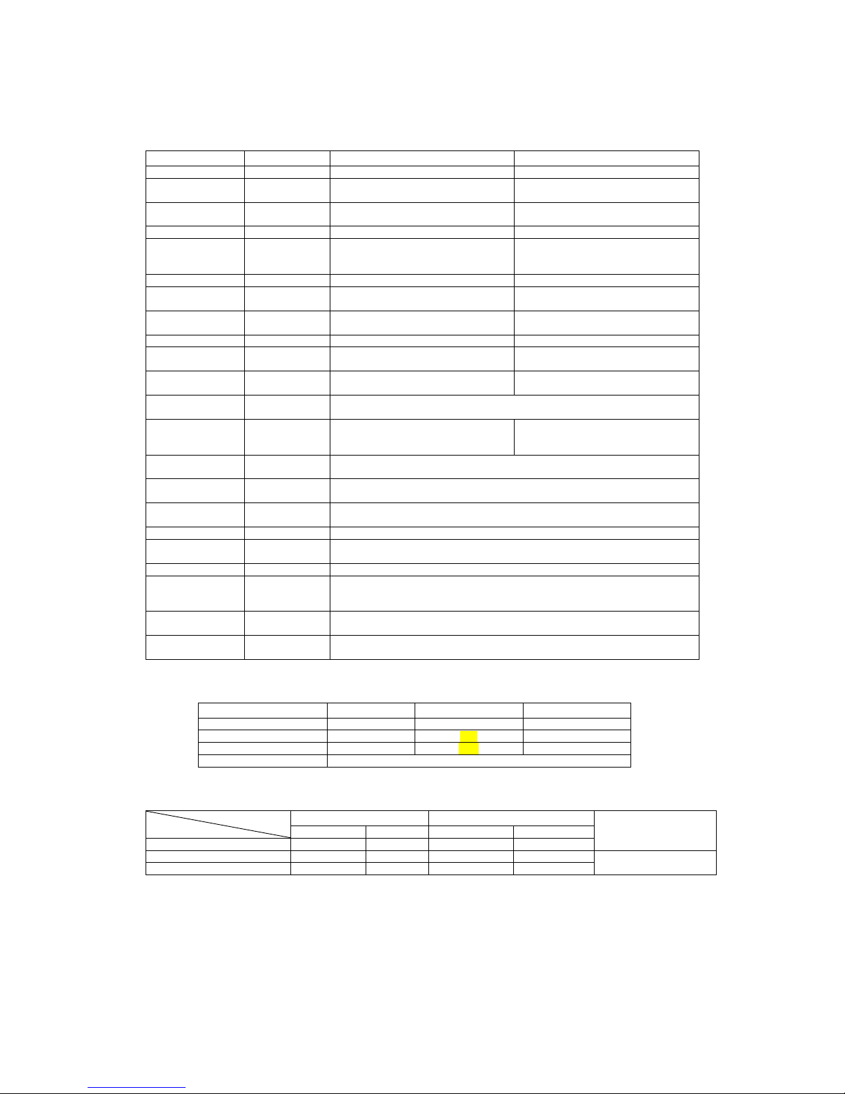
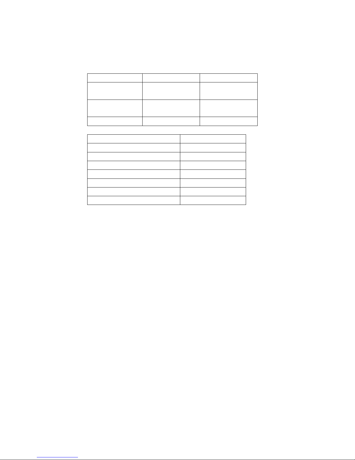
2.1.1 Model: SRK20MA–S (Indoor unit)
SRC20MA–S (Outdoor unit)
Item
Unit
Indoor unit SRK20MA–S
Outdoor unit SRC20MA–S
Net weight
kg
10
32
Machine
dimension
mm
798×230×294
780×290×540
Package
dimension
Length×
Width ×Height
850×365×310
920×380×590
Color White
Ash-colored
Fan
Through-flow type, AS resin +
glass fiber
Axial flow type, AS resin + glass
fiber (embedded damping spindle
sleeve)
Air flow
m3/h
600
1800
Noise in cool
room
dB(A)
Hi/Me/Lo: 37/27/21(completely
mute, SPL)
43(completely mute, SPL)
Noise in warm
room
dB(A)
Hi/Me/Lo: 37/28/24(completely
mute, SPL)
45(completely mute, SPL)
Fan motor
Nominal value
33W, DC motor, insulation grade E
24W, DC motor, insulation grade E
Power of motor
W (reference
value)
19
20
Power of electric
control
W (reference
value)
2
7.5
Power supply and
power cord
Single-phase, 220V, 50Hz and 3-core, 1.0mm2, 250V, 10A, 2m, w/o plug
Heat exchanger
Spiral, hydrophilic, 4-folded,
15-section, 2-row, 528-fin, 1-2
circuit
Spiral, hydrophilic, 20-section,
1-row, 621-fin, 2-1 circuit
Compressor
Nominal value
THACOM RM-B5077MDE2, 527W, DC frequency conversion
compressor, insulation grade E
Refrigerating
machine oil
ml
300, DIAMOND FREEZE MA68
Refrigerant
controller
Electronic expansion valve (Φ1.5mm) + hush pipe
Refrigerant
g
R-410A, 900g, addition/reduction not needed within the use range of 15m
Operating
pressure limit
Mpa
Max.: 4.15, Min.: 1.47
Air filters
Lysozyme filter + Antibacterial deodorizing filter + Mould-proof air filter
Accessories and
quantity
Indoor unit 1, mounting plate 1, tapping screw 5, battery 2, use and
installation manual 1, remote controller 1, filter components 2, outdoor unit
1, Drain elbow 1, Water shutoff plug 1
Operation control
devices
Wireless remote controller, electronic thermostat controlling room
temperature, microcomputer controlling defrosting
Safety devices
Serial signal protection, fan error protection, compressor over heat
protection, high voltage protection, over current protection, etc.
* The nominal values of “Noise in cool room” and “Noise in warm room” in the above table are tested in a dead
room.
Item
Unit
Rating cooling
Rating heating
Capacity
W
2000
2700
Power
W
450
600
Energy efficiency ratio
4.44
4.50
Energy efficiency grade
Grade A (European norm)
Note (1) The data are measured at the following conditions. The pipe length is 5m.
Item
Operation
Indoor air temperature
Outdoor air temperature
Standards
DB
WB
DB
WB
Cooling
27℃
19℃
35℃
24℃
Heating
20℃
—
7℃
6℃
Low temperature Heating
20℃ — 2℃
1℃
(2) The operation data are applied to the 220Vdistricts respectively.
(3) The refrigerant quantity to be charged includes the refrigerant in 15m connecting piping.
(Purging is not required even for the short piping.)
- 3 -
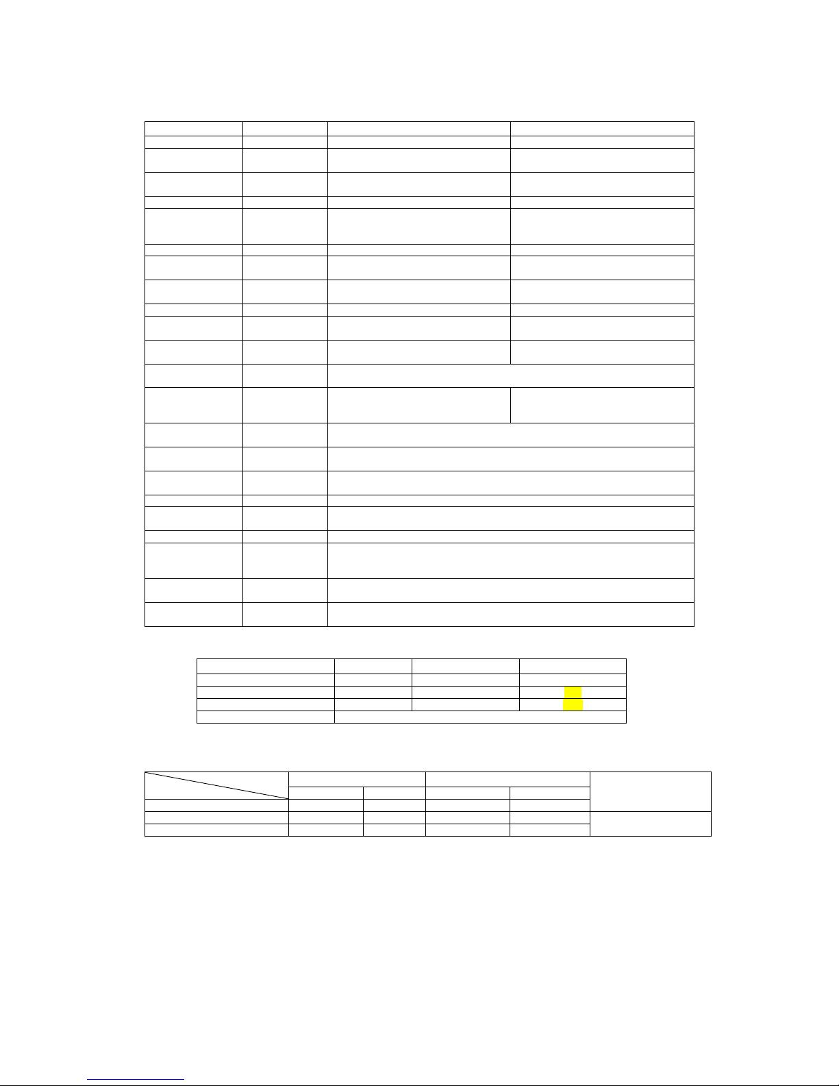
2.1.2 Model: SRK25MA–S (Indoor unit)
SRC25MA–S (Outdoor unit)
Item
Unit
Indoor unit SRK25MA–S
Outdoor unit SRC25MA–S
Net weight
kg
10
32
Machine
dimension
mm
798×230×294
780×290×540
Package
dimension
Length×
Width ×Height
850×365×310
920×380×590
Color White
Ash-colored
Fan
Through-flow type, AS resin +
glass fiber
Axial flow type, AS resin + glass
fiber (embedded damping spindle
sleeve)
Air flow
m3/h
600
1800
Noise in cool
room
dB(A)
Hi/Me/Lo: 37/27/22(completely
mute, SPL)
44(completely mute, SPL)
Noise in warm
room
dB(A)
Hi/Me/Lo: 38/29/23(completely
mute, SPL)
45(completely mute, SPL)
Fan motor
Nominal value
33W, DC motor, insulation grade E
24W, DC motor, insulation grade E
Power of motor
W (reference
value)
19
20
Power of electric
control
W (reference
value)
2
7.5
Power supply and
power cord
Single-phase, 220V, 50Hz and 3-core, 1.0mm2, 250V, 10A, 2m, w/o plug
Heat exchanger
Spiral, hydrophilic, 4-folded,
15-section, 2-row, 528-fin, 1-2
circuit
Spiral, hydrophilic, 20-section,
1-row, 621-fin, 2-1 circuit
Compressor
Nominal value
THACOM RM - B5077MDE2, 527W, DC frequency conversion
compressor, insulation grade E
Refrigerating
machine oil
ml
300, DIAMOND FREEZE MA68
Refrigerant
controller
Electronic expansion valve (Φ1.5mm) + hush pipe
Refrigerant
g
R-410A, 900g, addition/reduction not needed within the use range of 15m
Operating
pressure limit
Mpa
Max.: 4.15, Min.: 1.47
Air filters
Lysozyme filter + Antibacterial deodorizing filter + Mould-proof air filter
Accessories and
quantity
Indoor unit 1, mounting plate 1, tapping screw 5, battery 2, use and
installation manual 1, remote controller 1, filter components 2, outdoor unit
1, water elbow 1, Water shutoff plug 1
Operation control
devices
Wireless remote controller, electronic thermostat controlling room
temperature, microcomputer controlling defrosting
Safety devices
Serial signal protection, fan error protection, compressor over heat
protection, high voltage protection, over current protection, etc.
* The nominal values of “Noise in cool room” and “Noise in warm room” in the above table are tested in a dead
room.
Item
Unit
Rating cooling
Rating heating
Capacity
W
2500
3200
Power
W
680
790
Energy efficiency ratio
3.68
4.05
Energy efficiency grade
Grade A (European norm)
Note (1) The data are measured at the following conditions. The pipe length is 5m.
Item
Operation
Indoor air temperature
Outdoor air temperature
Standards
DB
WB
DB
WB
Cooling
27℃
19℃
35℃
24℃
Heating
20℃
—
7℃
6℃
Low temperature Heating
20℃ — 2℃
1℃
(2) The operation data are applied to the 220Vdistricts respectively.
(3) The refrigerant quantity to be charged includes the refrigerant in 15m connecting piping.
(Purging is not required even for the short piping.)
- 4 -
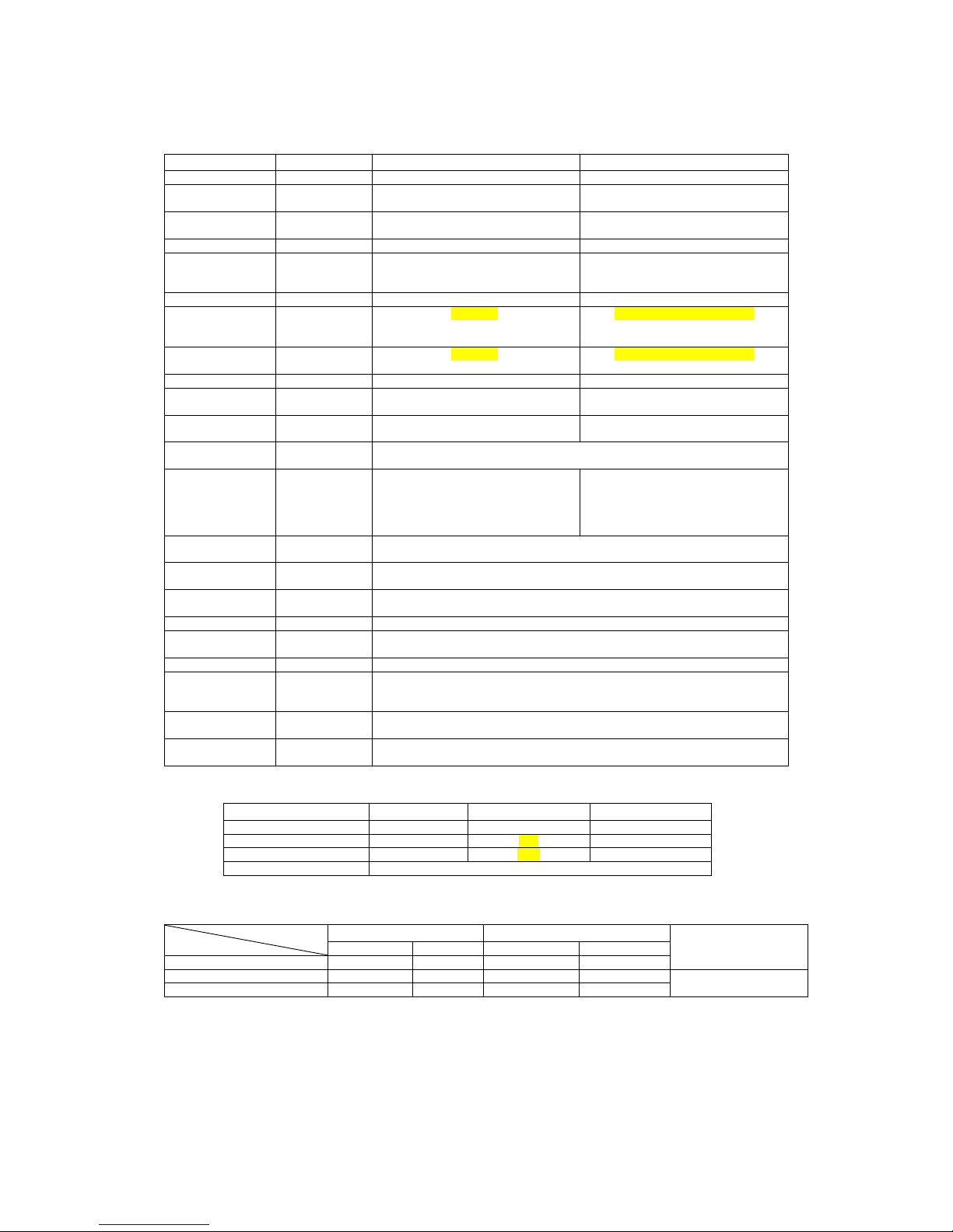
2.1.2 Model: SRK35MA–S (Indoor unit)
SRC35MA–S (Outdoor unit)
Item
Unit
Indoor unit SRK35MA–S
Outdoor unit SRC35MA–S
Net weight
kg
10.5
35
Machine
dimension
mm
798×230×294
780×290×540
Package
dimension
Length×
Width ×Height
850×365×310
920×380×590
Color White
Ash-colored
Fan
Through-flow type, AS resin +
glass fiber
Axial flow type, AS resin + glass
fiber (embedded damping spindle
sleeve)
Air flow
m3/h
600
1870
Noise in cool
room
dB(A)
Hi/Me/Lo: 39/31/23(completely
mute, SPL)
46(completely mute, SPL)
Noise in warm
room
dB(A)
Hi/Me/Lo: 41/34/23(completely
mute, SPL)
50(completely mute, SPL)
Fan motor
Nominal value
33W, DC motor, insulation grade E
24W, DC motor, insulation grade E
Power of motor
W (reference
value)
19
20
Power of electric
control
W (reference
value)
2
7.5
Power supply and
power cord
Single-phase, 220V, 50Hz and 3-core, 1.0mm2, 250V, 10A, 2m, w/o plug
Heat exchanger
Parent: Spiral, hydrophilic,
4-folded, 15-section, 2-row,
528-fin, Pf1.2
Child: Spiral, hydrophilic,
4-section, 1-row, 452-fin, Pf1.4
Spiral, hydrophilic, 20-section,
2-row, 1221-fin, 2-1 circuit, Pf1.4
Compressor
Nominal value
THACOM RM - B5077MDE2, 527W, DC frequency conversion
compressor, insulation grade E
Refrigerating
machine oil
ml
300, DIAMOND FREEZE MA68
Refrigerant
controller
Electronic expansion valve (Φ1.5mm) + hush pipe
Refrigerant
g
R-410A, 900g, addition/reduction not needed within the use range of 15m
Operating
pressure limit
Mpa
Max.: 4.15, Min.: 1.47
Air filters
Lysozyme filter + Antibacterial deodorizing filter + Mould-proof air filter
Accessories and
quantity
Indoor unit 1, mounting plate 1, tapping screw 5, battery 2, use and
installation manual 1, remote controller 1, filter components 2, outdoor unit
1, Drain elbow 1, Water shutoff plug 1
Operation control
devices
Wireless remote controller, electronic thermostat controlling room
temperature, microcomputer controlling defrosting
Safety devices
Serial signal protection, fan error protection, compressor over heat
protection, high voltage protection, over current protection, etc.
* The nominal values of “Noise in cool room” and “Noise in warm room” in the above table are tested in a dead
room.
Item
Unit
Rating cooling
Rating heating
Capacity
W
3500
4000
Power
W
960
1100
Energy efficiency ratio
3.65
3.64
Energy efficiency grade
Grade A (European norm)
Note (1) The data are measured at the following conditions. The pipe length is 5m.
Item
Operation
Indoor air temperature
Outdoor air temperature
Standards
DB
WB
DB
WB
Cooling
27℃
19℃
35℃
24℃
Heating
20℃
—
7℃
6℃
Low temperature Heating
20℃ — 2℃
1℃
(2) The operation data are applied to the 220Vdistricts respectively.
(3) The refrigerant quantity to be charged includes the refrigerant in 15m connecting piping.
(Purging is not required even for the short piping.)

- 5 -
2.1.2 Model: SRK50MA–S (Indoor unit)
SRC50MA–S (Outdoor unit)
Item
Unit
Indoor unit SRK50MA–S
Outdoor unit SRC50MA–S
Net weight
kg
10.5
43
Machine
dimension
mm
798×230×294
850×290×640
Package
dimension
Length×
Width ×Height
850×365×310
990×395×700
Color White
Ash-colored
Fan
Through-flow type, AS resin +
glass fiber
Axial flow type, AS resin + glass
fiber (embedded damping spindle
sleeve)
Air flow
m3/h
720
2400
Noise in cool
room
dB(A)
Hi/Me/Lo: 44/34/25(completely
mute, SPL)
50(completely mute, SPL)
Noise in warm
room
dB(A)
Hi/Me/Lo: 48/34/25(completely
mute, SPL)
50(completely mute, SPL)
Fan motor
Nominal value
33W, DC motor, insulation grade E
24W, DC motor, insulation grade E
Power of motor
W (reference
value)
19
20
Power of electric
control
W (reference
value)
2
7.5
Power supply and
power cord
Single-phase, 220V, 50Hz and 3-core, 1.5mm2, 250V, 16A, 2m, w/o plug
Heat exchanger
Parent: Spiral, hydrophilic,
4-folded, 15-section, 2-row,
528-fin, Pf1.2
Child: Spiral, hydrophilic,
4-section, 1-row, 452-fin, Pf1.4
Spiral, hydrophilic, 24-section,
2-row, 1334-fin, 4-1 circuit, Pf1.2
Compressor
Nominal value
THACOM RM - B5077MDE2, 527W, DC frequency conversion
compressor, insulation grade E
Refrigerating
machine oil
ml
300, DIAMOND FREEZE MA68
Refrigerant
controller
Electronic expansion valve (Φ1.5mm) + hush pipe
Refrigerant
g
R-410A, 1250g, addition/reduction not needed within the use range of 15m
Operating
pressure limit
Mpa
Max.: 4.15, Min.: 1.47
Air filters
Lysozyme filter + Antibacterial deodorizing filter + Mould-proof air filter
Accessories and
quantity
Indoor unit 1, mounting plate 1, tapping screw 5, battery 2, use and
installation manual 1, remote controller 1, filter components 2, outdoor unit
1, Drain elbow 1, Water shutoff plug 1
Operation control
devices
Wireless remote controller, electronic thermostat controlling room
temperature, microcomputer controlling defrosting
Safety devices
Serial signal protection, fan error protection, compressor over heat
protection, high voltage protection, over current protection, etc.
* The nominal values of “Noise in cool room” and “Noise in warm room” in the above table are tested in a dead
room.
Item
Unit
Rating cooling
Rating heating
Capacity
W
5000
5800
Power
W
1560
1600
Energy efficiency ratio
3.21
3.63
Energy efficiency grade
Grade A (European norm)
Note (1) The data are measured at the following conditions. The pipe length is 5m.
Item
Operation
Indoor air temperature
Outdoor air temperature
Standards
DB
WB
DB
WB
Cooling
27℃
19℃
35℃
24℃
Heating
20℃
—
7℃
6℃
Low temperature Heating
20℃ — 2℃
1℃
(2) The operation data are applied to the 220Vdistricts respectively.
(3) The refrigerant quantity to be charged includes the refrigerant in 15m connecting piping.
(Purging is not required even for the short piping.)
- 6 -
2.2 Range of usage
Please use the air conditioners within the following range of usage, otherwise the protector will be
triggered.
Cooling Operation
Heating Operation
Outdoor temperature
About 18℃~43℃
About -15~24℃
Indoor temperature
About18℃~32℃
About below 30℃
Indoor humidity
About below 80%
20~50 Models
Max. piping one-way length
Within 15 m
Vertical height difference
Within 5 m
Additional R410A Refrigerant
Not required
Voltage
Rating ±10%
Starting voltage
At least 85% of rating
Switching frequency
Max. 10 times per hour
Time interval between stop and start
Min. 3 min
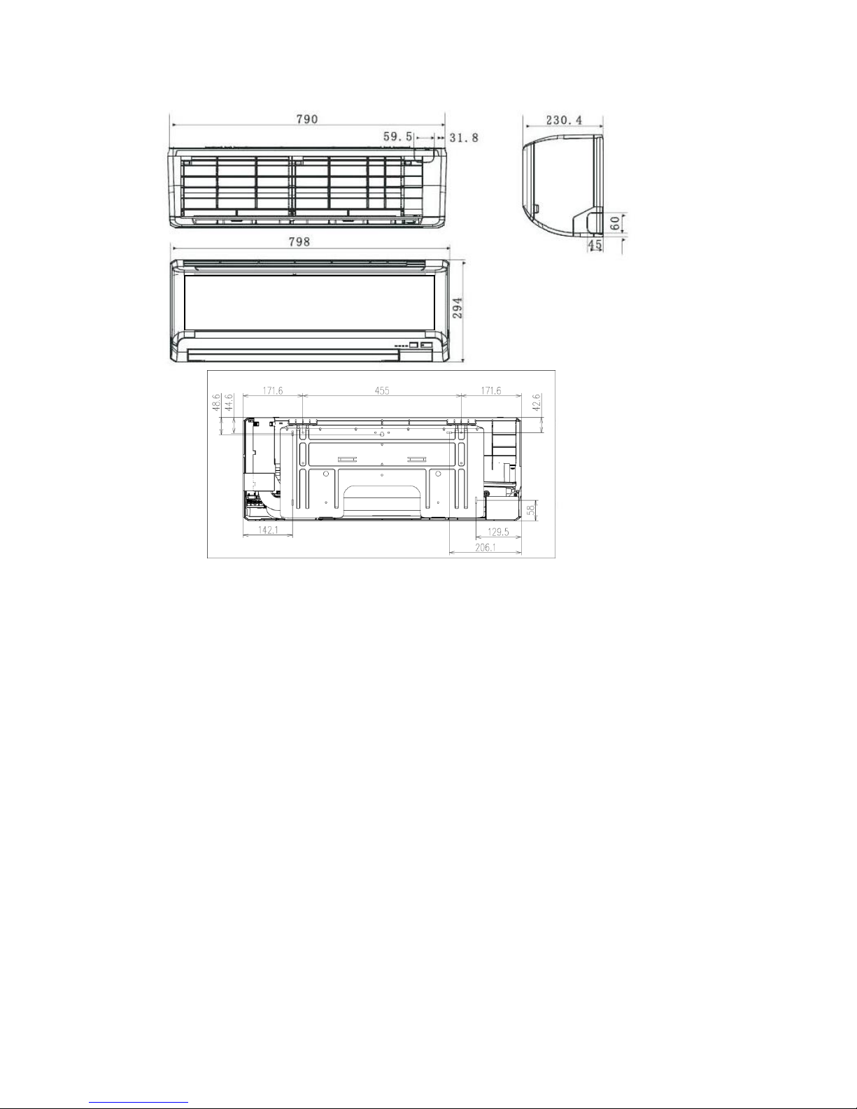
2.3 Outline drawing
(1) Indoor unit: MA-S Series Unit: mm
- 7 -
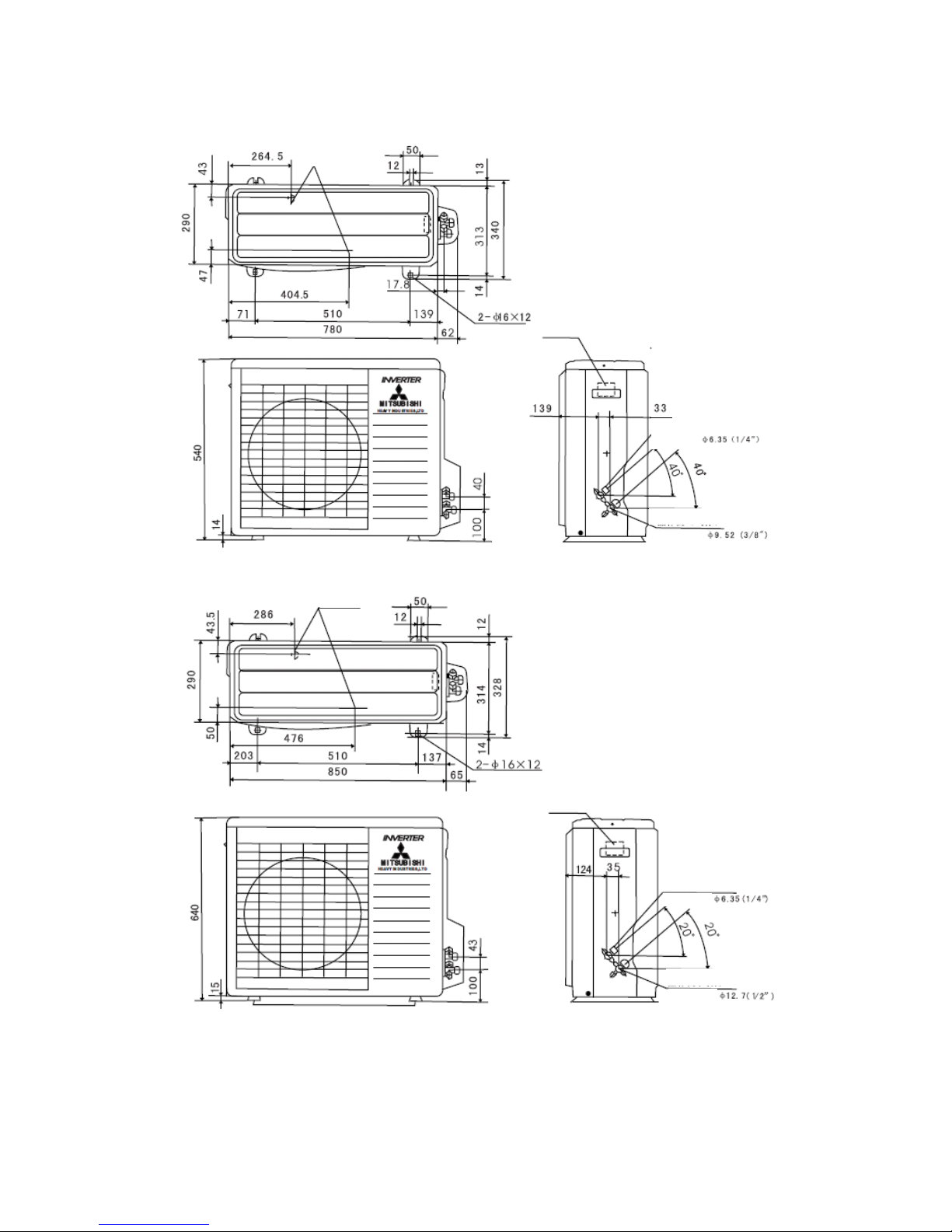
- 8 -
(2) Outdoor unit: SRC20MA-S/ SRC25MA-S/ SRC35MA-S Unit: mm
(3) Outdoor unit: SRC50-MA-S Unit: mm
Drainage pipes
Junction box
Operation valve (Liquid)
Flare connecting
Operation valve (Gas)
Flare connecting
Drain holes
Terminal block
Operation valve (Liquid)
Flare connecting
Operation valve (Gas)
Flare connecting
- 9 -
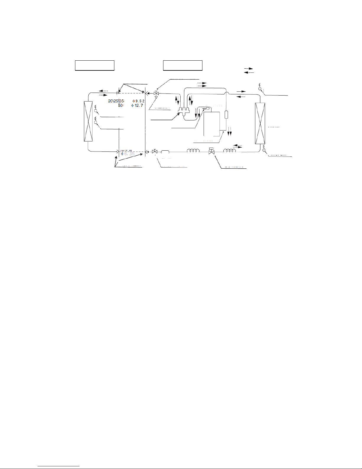
2.4 Cooling cycle system diagram
Models: MA-S Series
Note (1)……line is piping for site construction.
Indoor unit
Outdoor unit
Circulation of cooling
Circulation of heating
Flare connecting
Operation valve (Gas)
Outdoor air
temp. sensor
Air heat
exchanger
Heat exchanger
sensor
Gas liquid
separator
Compressor
Discharge pipe sensor
4-way valve
Check joint
Gas pipe Note (1)
model
Air heat
exchanger
Inlet air temp.
sensor
Air heat exchanger
sensor
Liquid pepe
Flare connecting
Filter
Electronic expansion valve
Hush pipe
Hush pipe
Operation valve (Liquid)
Refrigerant inlet pipe
Refrigerant outlet
pipe
model
- 10 -
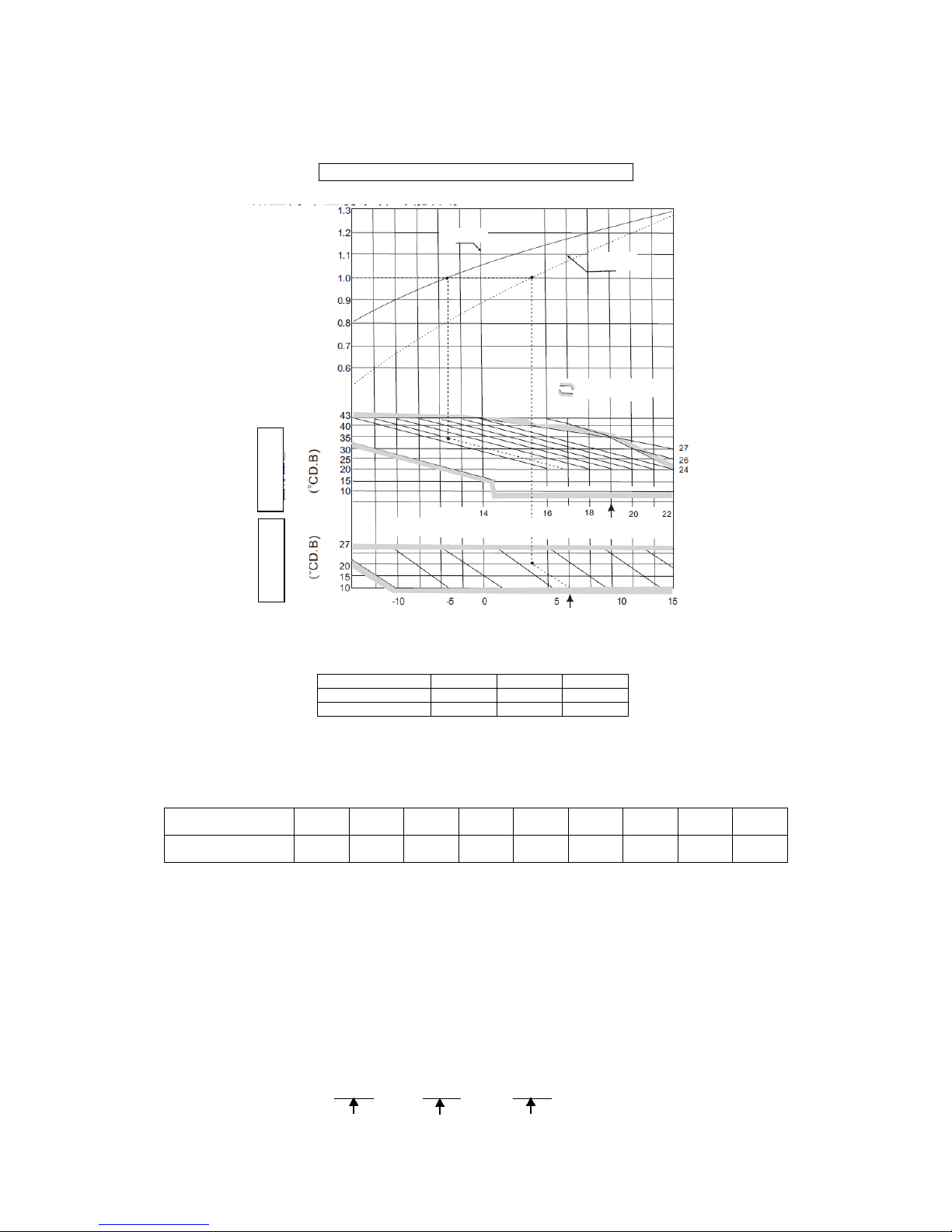
2.5 Performance curve
The cooling and heating capacities are measured in the following conditions. The actual capacity can
be obtained with the following formula.
Actual capacity = Rating capacity x Correction factor
(1) Capacity correction according to indoor and outdoor temperatures:
Outdoor air W.B. temperature (°C W.B.) ISO-T1 Standard
⑵ Capacity correction according to one way length of refrigerant piping:
It is necessary to correct the cooling and heating capacity according to the one way length of refrigerant
piping.
Piping length (m)
7
10
15
Cooling
1.0
0.99
0.975
Heating
1.0
1.0
1.0
⑶ Capacity correction according to frosting on outdoor heat exchanger during heating:
In additions to the foregoing corrections (1) and (2), the heating capacity also needs to be corrected
according to the frosting on the outdoor heat exchanger.
Air inlet temperature
of outdoor unit
-10
-9
-7
-5
-3
-1 1 3 5 Frosting correction
factor
0.95
0.94
0.93
0.91
0.88
0.86
0.87
0.92
1.00
⑷ Example of cooling and heating capacity calculation:
The actual cooling capacity of model SRK50MA-S with the one way piping length of 25m at the
indoor wet-bulb temperature of 19℃ and outdoor dry-bulb temperature of 35℃in summer or indoor
dry-bulb temperature of 20℃, outdoor dry-bulb temperature of 1℃and indoor wet-bulb temperature of
-1℃ in winter is
Actual cooling capacity = 5000 x 1.0 x 0.95 ≈ 4750W
Cooling
Heating
Accommodation
Correction factor of cooling & heating
capacity in relation to temperature
Cooling operation
Heating operation
Indoor air D.B.
temperature
Outdoor air D.B.
temperature
Indoor air W.B. temperature (°C W.B) ISO-T1 Standard

- 11 -
Nominal cooling Temp. correction Piping length
capacity factor correction factor
Actual heating capacity = 5800 x 0.81 x 0.95 x 0.86 ≈ 3838W
Nominal heating Temp. correction Piping length Frosting
capacity factor correction factor correction factor
- 12 -
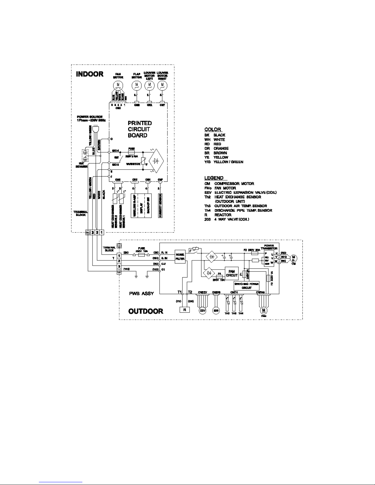
3 ELECTRICAL WIRING DIAGRAM
3.1 Circuit diagram: 20, 25, 35MA-S

- 13 -
3.2 Circuit diagram: 50MA-S
- 14 -
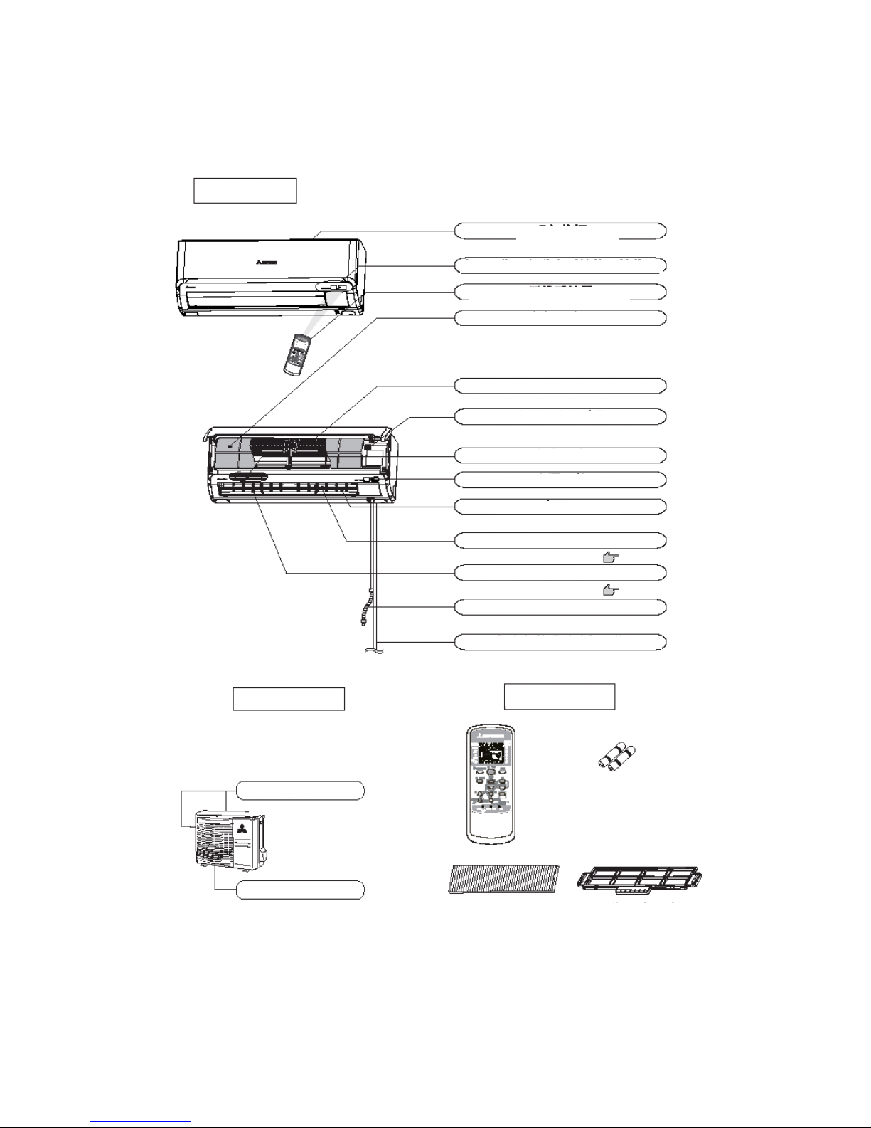
4 NAME OF EACH PART AND ITS FUNCTION
4.1 Name of each part
Indoor unit
Suctions air in the room
Wireless remote controller
Air filter
Page 19
Filter
Indoor fan
Power switch
Vent
Air blows from here.
Up/down air direction flap
Page 11
Left/right air direction flap
Page 11
Drainage pipe
Drains water removed from air
Refrigerant pipe joint and electric wire
Outdoor unit
Accessories
Air inlet
Vent
(on the side and back)
Batteries
Wireless remote controller
Filter retainer (2 pcs)
Lysozyme filter and
antibacterial deodorizing filter
Indication section of A/C and signal receiver of remote controller
Air inlet panel
Draws in the indoor air.
Removes dust or dirt from the inlet air
Room temperature detector
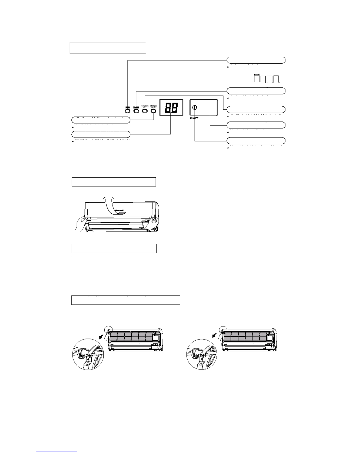
- 15 -
Indication section of air conditioner
RUN lamp (green)
ON during running
Heat-retaining
Running
Stop
1.5 sec.
0.5 sec.
ON during HI POWER/JET running
TIMER lamp (yellow)
ON during timing operation
HI POWER/JET lamp (green)
Receiving part of remote controller
Receives signals from remote controller
ON/OFF button
Press this button to begin
running; press it again to stop
running.
POWER SAVE lamp (green)
ON during Power Save running
Temp. displaying lamp (olivine)
It displays the room temperature or
set temperature. (Each time the
remote controller is pressed, the
temperature set with the remote
controller flashes for 10 seconds,
and then the room temperature is
displayed.
Opening the air inlet grille
Put your hands on the indentations on both sides, raise the grille towards yourself, and stop at the opening position of
about 60°.
Closing the air inlet grille
Gently push both sides and then gently push the central portion.
Removing and mounting the air inlet grille
To remove the air inlet grille to clean the inside, open it
at the position of about 65° and pull it towards yourself
to remove the grille.
To mount the air inlet grille, insert the mounting arm
onto the pin roll and close the grille.
- 16 -
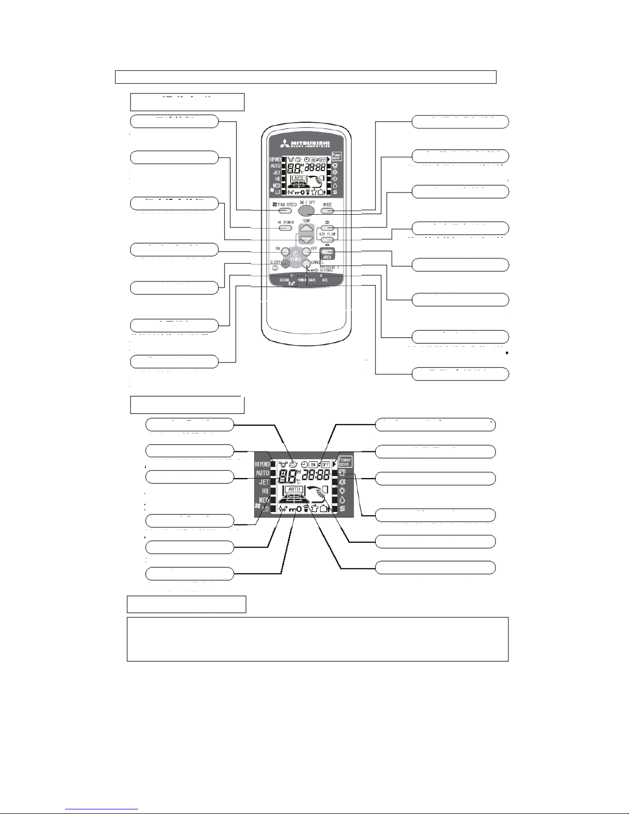
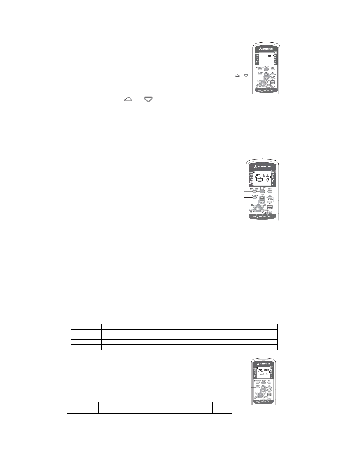
Operation and indication section for remote control
Operation section
FAN SPEED button
Each time this button is pressed,
■ displaying changes in order.
HI POWER button
This button is used to change
the HI POWER mode.
TEMP button
This button is used to set the room
temp. (or select the current time
and set time for timing operation.)
TIMER ON button
This button is used to select
the Timing ON operation.
SLEEP button
Press this button to switch to
the SLEEP operation.
CLEAN button
Press this button to switch to
the CLEAN mode.
POWER SAVE button
Press this button to switch to the
POWER SAVE mode.
Displaying section
SLEEP indicator
Appears in the SLEEP mode
HI POWER indicator
■ is used to indicate the HI POWER mode
TEMP indicator
Displays the set temperature
(No temperature is displayed in
the AUTO mode.
FAN SPEED indicator
■ is used to indicate the fan speed set.
CLEAN indicator
Appears in the CLEAN mode
KEY LOCK indicator
Appears in the CLEAN mode
Transmission method
MODE button
Each time this button is pressed, ■
displaying changes in order.
ON/OFF (luminous) button
Press this button to begin running;
press it again to stop running.
Up/Down air direction button
Press this button and the air flap begins
to swing upwards and downwards.
Left/Right air direction button
Press this button and the air flap begins to
swing to the left and the right.
AREA button
Press this button to set the air
regulation area in the room.
TIMER OFF button
This button is used to select the
Timing OFF operation.
ACL switch
Used to reset the microcomputer
CANCEL/KEY LOCK button
Press this button to cancel Timing ON/OFF
and SLEEP operations; press and hold it for 3
seconds to lock the functional keys.
Timing ON/ Timing OFF indicator
Appears in the Timing ON/ Timing OFF mode
Power Save indicator
Indicates the POWER SAVE mode
MODE indicator
■ is used to indicate the mode selected:
[AUTO/ COOLING/ HEATING/ DRYING/ BLOW]
TIME indicator
Displays the current time or the set time of the timer
AIR FLOW indicator
Displays the swinging mode of the flap
AREA indicator
Displays the air regulation area in the room
When the remote controller is pointed at the air conditioner, press a button on the remote controller and the signal will be
transmitted to the air conditioner. When the signal is received correctly, the air conditioner will issue the receiving sound. The
effective linear distance of transmission of the remote controller is 5 meters. The transmission head of the remote controller
should be pointed at the receiving head, otherwise, the receiving may be impacted.
● The above figure shows all
control contents for convenient
explanation. However, in actual
use, only related contents are
displayed.
- 17 -
4.2 Emergency switch:
(1) When the remote controller is not used, the emergency operation switch “ON/OFF” button
can be used to turn on/off the machine.
(2) Press the “ON/OFF” button to begin operation. Press it
again to stop.
(3) Operation items:
● Operating mode: Automatic
● Fan speed: Automatic
● Air direction: Automatic
(4) Note:
Press and hold it for over 5 seconds to set to the cooling mode automatically.
4.3 Automatic restart due to power cut:
(1) This function can rapidly record the operation state immediately before the air conditioner is
switched off due to power failure, and will resume operation automatically after the power
supply is restored.
(2) This function is set to Active by default.
(3) Operation state memorized immediately before power cut includes:
● Indoor operation switching (cool room · warm room · drying · automatic · air flow, stop)
● Air flow
● Power Save
● Set temperature
● Air direction
(4) After automatic restart due to power cut, the following settings will be canceled:
Timing operation, HI POWER operation, CLEAN operation
(5) Priority of start:
Compressor 3 min. delayed start control > Automatic restart due to power cut
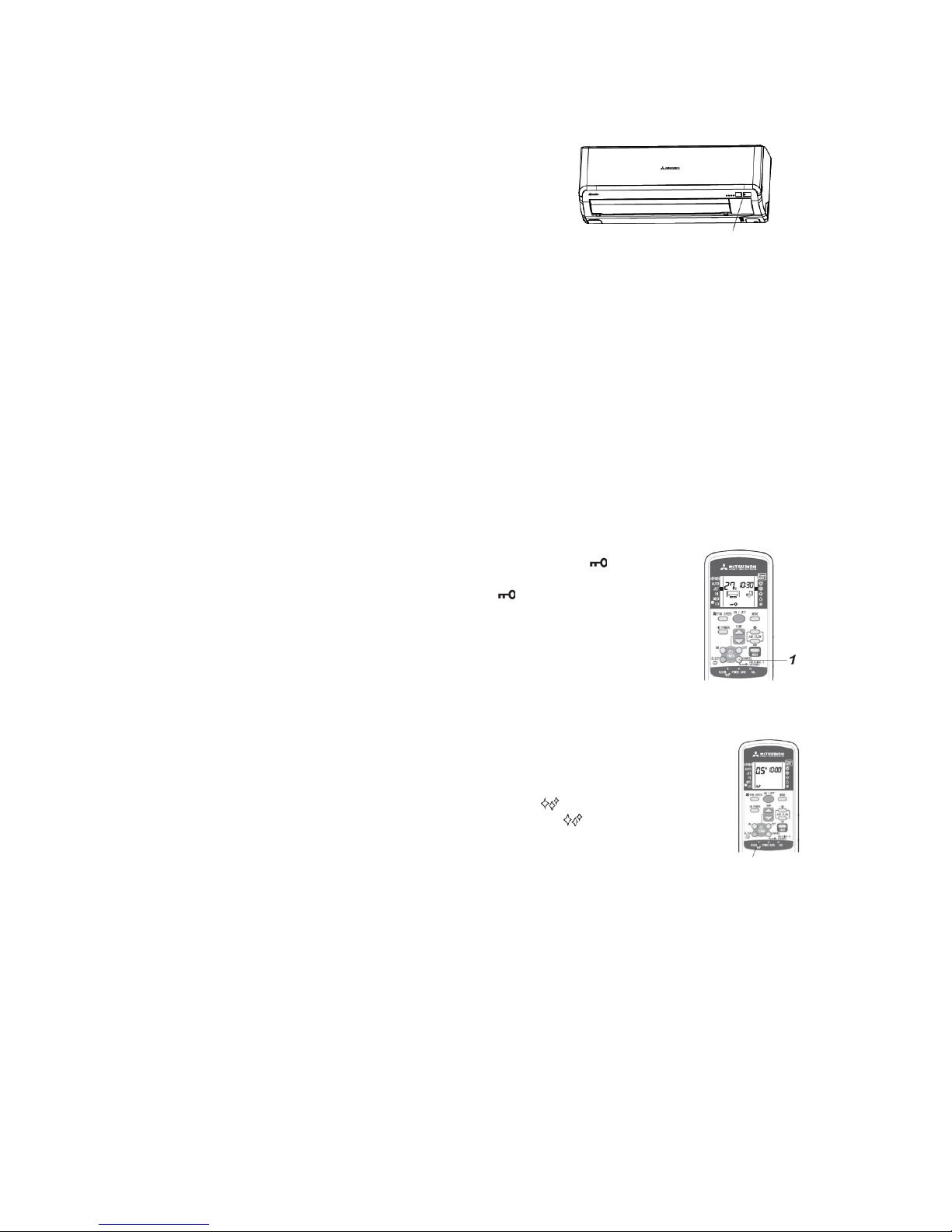
4.4 Key lock:
(1) The key lock setting prevents misoperation.
(2) Press and hold the KEY LOCK button for over 3 seconds and will appear
on the remote controller, which means the function is enabled; press and hold
the KEY LOCK button for over 3 seconds and on the remote controller
will disappear, which means the function is disabled
(3) When the function is enabled, only the ON/OFF button can be operated, and
the settings of temperature, air flow, air direction, etc. can’t be changed.
(4) When the function is enabled in the JET/ HI POWER operating mode, the
operation and action are valid before the air conditioner stops and become
invalid when the air conditioner operates again.
(5) The key lock function can’t be set in the CLEAN operation and various timing operations.
4.5 CLEAN operation:
(1) CLEAN operation: In the automatic, cooling and drying operating modes, when the
air conditioner is turned off, the fan of the indoor unit will continue to run for 30
minutes to dry the moisture in the indoor unit and inhibit the growth of mould and
bacteria. However, mould, bacteria, stain, etc. attached can’t be removed.
(2) Press the CLEAN button on the remote controller and will appear, which
means the CLEAN function is enabled; press it again and will disappear,
which means the CLEAN operation is disabled.
(3) After the CLEAN function is enabled, in the automatic/cooling/drying mode, press
the ON/OFF button to stop the operation of the air conditioner. In such case, the
RUN lamp will go off; the CLEAN indicator on the remote controller will light up; and the
CLEAN operation will run for about 30 minutes.
(4) During the CLEAN operation, press the ON/OFF button and the CLEAN operation will stop.
(5) According to the relative humidity, the rotate speed of the fan will be selected automatically
(including 3 rotate speeds) and will not be changed during the operation.
(6) When Air Flow, Timing On and SLEEP Operation stop, the CLEAN operation can’t run.
(7) During the CLEAN operation, press the SLEEP button and the CLEAN operation will be
switched to the SLEEP operation.
(8) The CLEAN function is disabled by default. Users need to set it according to the above steps.
ON/OFF button of the equipment
CLEAN
- 18 -
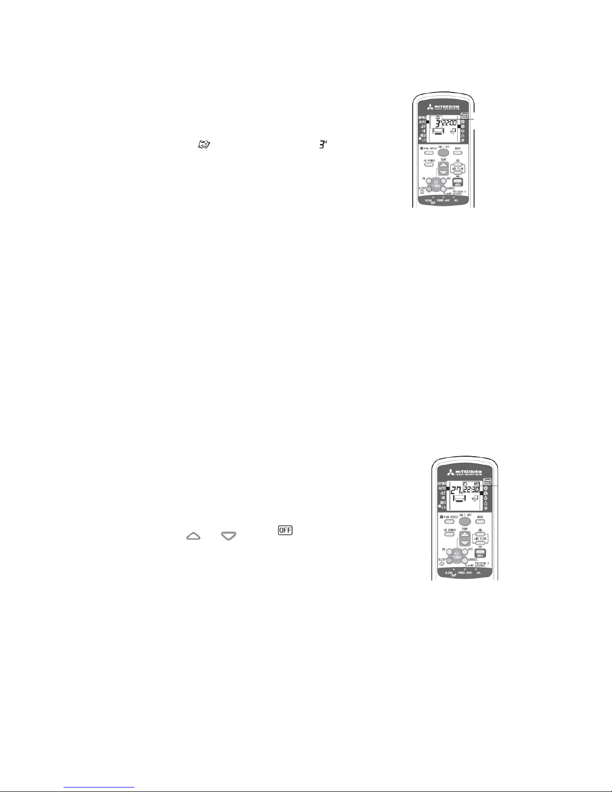
4.6 SLEEP operation:
(1) SLEEP operation: This function prevents the temperature in the cooling operation from
becoming too low and the temperature in the heating operation from
becoming too high; regulates the room temperature automatically as
time goes by; and stops automatically after the time set.
(2) Operation method:
① If the SLEEP button is pressed during the operation of the air
conditioner, and the run time, such as , will appear.
There are 11 options, including 1-10 hours (interval of 10 hours)
and OFF.
② If the SLEEP button is pressed when the air conditioner is in the
stop mode, the air conditioner will execute the previous
operation settings and stop after the time set.
(3) Making correction based on the set temperature and regulating the
room temperature automatically:
① During cooling operation:
Beginning (-1℃), 1 hour later (±0℃), 2 hours later (+1℃);
② During heating operation:
Beginning (-1℃), 30 minutes later (-2℃), 1 hour later (-1℃), 2 hours later (-6℃); 4 hours
later (-3℃)
(4) The set time of SLEEP operation can be changed with the SLEEP button at any time. Since
the remote controller receives the change signal, the air conditioner continues to run
according to the changed set time.
(5) When the operation switch change signal is received during the SLEEP operation, the air
conditioner will control the sleep setting according to the operation switching and the
temperature correction value in the elapsed time will be retained.
(6) When the set temperature change signal is received during the SLEEP operation, the
temperature correction value will be recalculated.
(7) When the air conditioner is set to automatic control (fuzzy automatic) and the indoor
operating mode (cool room · drying · warm room) is set, the SLEEP operation begins. The
change of cool room · drying · warm room state arising from the automatic control (fuzzy
automatic) is made only when the set temperature is changed. (In other words, the operating
mode judgment according to the operation judgment timing is not executed.)
(8) Priority of sleep timing operation
① Set temperature correction: HI POWER operation > Setting correction temperature
② Timing: Sleep timing run > HI POWER run
4.7 Timing OFF:
(1) Timing OFF: The timing OFF operation begins when the Timing OFF
signal is received from the remote controller and stops after the set time.
(2) Operation method:
① When the air conditioner is in the stop mode, press the ON/OFF
button;
② When the air conditioner is running, press the TIMER OFF button
and the Timing OFF indicator will flash;
③ Press the or button to set the OFF time (unit: 10
minutes);
④ Within 60 seconds, press the TIMER OFF button and the indicator
will change from flashing to a fixed state. The setting is finished;
⑤ The TIMER lamp (yellow) of the indoor unit lights up.
(3) Use the TIMER OFF button to set a new Timing OFF time at any time.
(4) During the Timing OFF operation, all setting change signals from the remote controller are
accepted.
(5) During the Timing OFF operation, when the Timing ON signal is received, the operation will
become the programmed timing operation and the remaining Timing OFF time will be
retained.
(6) During the Timing OFF operation, when the Sleep signal is received, the Timing OFF
operation will be canceled (and the remaining time will be canceled too) and the operation
will be switched to the SLEEP operation. (In other words, the SLEEP operation can’t be used
with the Timing OFF function.)
(7) To cancel the Timing OFF function, press the Cancel button and the TIMER lamp will go
off.
Sleep
timing
Timing
OFF
- 19 -
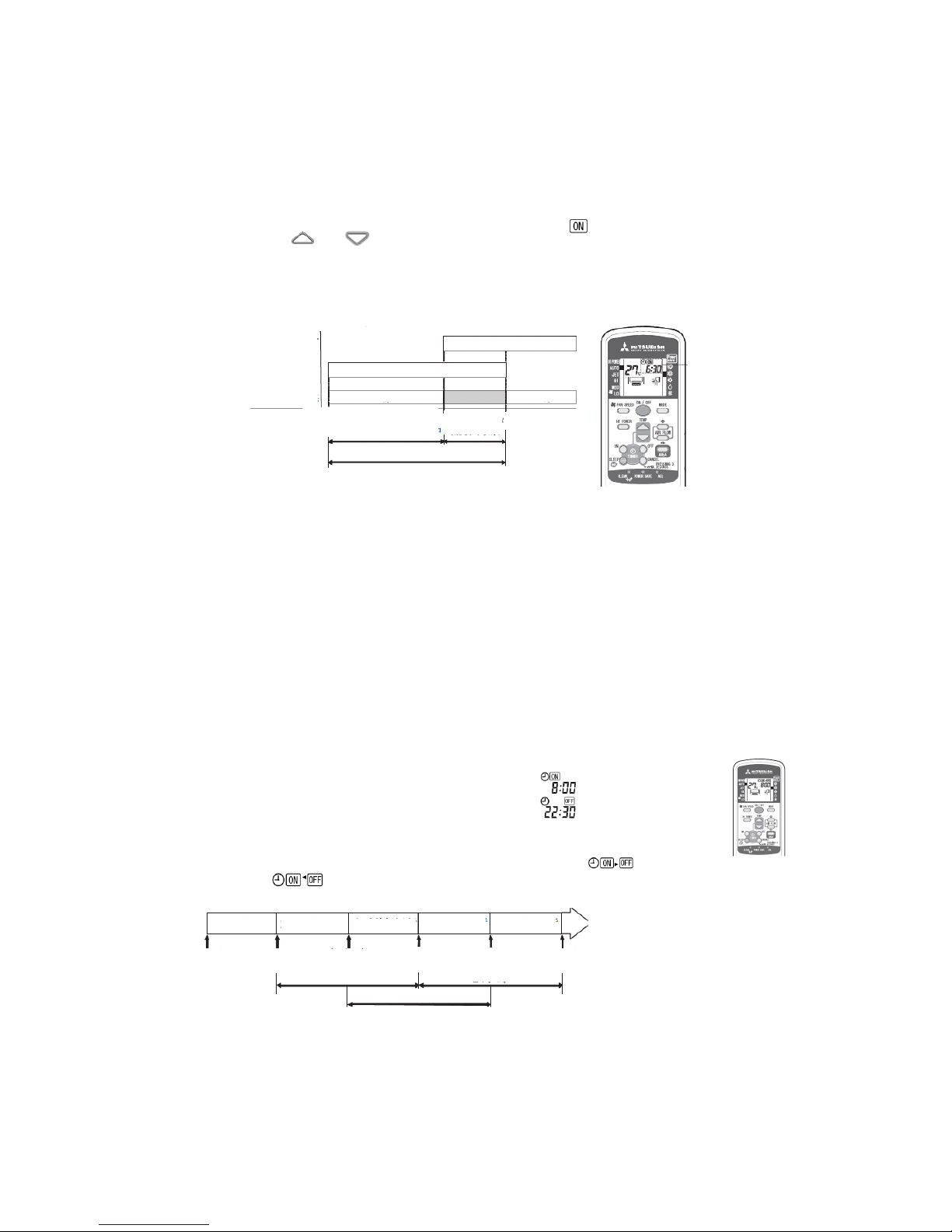
4.8 Timing ON:
(1) Timing ON: The air conditioner begins to detect the room temperature 60 minutes before
the set time and commences operation 5-60 minutes in advance according to the difference
between the room temperature and the set temperature to make the room temperature reach
the best value at the set time.
(2) Operation method:
① To set the Timing ON operation, whether the air conditioner is running is not considered.
② Press the TIMER ON button and the Timing ON lamp will flash;
③ Press the or button to set the ON time (unit: 10 minutes);
④ Within 60 seconds, press the TIMER ON button and the lamp will change from flashing
to a fixed state. The setting is finished;
⑤ The TIMER lamp (yellow) of the indoor unit lights up.
(3) Composition of Timing ON operation:
(4) Notes:
① The air conditioner commences operation 5-60 minutes before the set time.
② When the time reaches the set time, the TIMER lamp (yellow) will go off;
③ During the Timing ON operation, the current time is not displayed.
(5) Use the TIMER ON button to set a new Timing ON time at any time and the air conditioner
will enter the stand-by state or warm-up running state after the changed set time.
(6) When the Timing OFF signal is received, the air conditioner will run in the timing mode with
an earlier set time.
(7) During the Timing ON operation and stand-by, when the operation switching, mode
switching or set temperature change signal is received from the remote controller, only the
changed content will be accepted.
4.9 Programmed timer:
(1) Timing operations include Timing ON and Timing OFF. Once the function is enabled, the
operation begins. As long as the ON/OFF button is not pressed, the air conditioner will begin
operation at the same time everyday till the stop time.
(2) Operation method:
For example, to set the air conditioner to turn on at 8:00 and turn off at 22:30,
① Step 1: By referring to “4.9 Timing ON”, set it to ;
② Step 2: By referring to “4.8 Timing OFF”, set it to ;
③ When the TIMER lamp (yellow) lights up, the setting is finished;
④ The time will be displayed on the remote controller;
⑤ The displaying will change with the operation state: Stop( ),
Run.( )
(3) Repeated running:
(4) Notes:
① The operation becomes programmed running only when both the Timing On and Timing
OFF signals are received;
② The Timing ON and Sleep combined operation is executed once only and will not
become programmed operation.
(5) Use the TIMER ON or OFF button to set new ON time.
Timing ON
RUN Lamp
TIMER Lamp
Running state of compressor
Lamp lights up
Lamp lights up
Stop
△Timing ON signal
Timing ON stand-by
Warm-up running
(MAX 1 hour)
△Timing ON set time
Timing ON running
Timing ON run
Timing ON run
Timing ON run
Timing OFF run
Timing OFF run
Timing OFF
setting
Timing OFF
set time
Timing ON
set time
24 hours
Timing ON
set time
24 hours
Timing OFF
set time
24 hours
Timing OFF
set time
- 20 -
4.10 Current time setting:
(1) After inserting the batteries, the current time is set to 13:00
automatically.
In time setting, all contents displayed on the remote controller
are reset.
(2) Operation method:
For example, to set to 11:30,
① Step 1: Use the pen point to press the ACL switch and the
TIMER lamp will flash. Here you can set the current time;
② Step 2: Press the or button to set the current time to 11:30;
③ Within 60 seconds, press the ON/OFF button and the lamp will change from flashing to a
fixed state, thus the setting is finished.
(3) Notes:
① Timing operation is set according to the current time;
② The time on the remote controller changes according to the setting of current time.
4.11 HI POWER operation
(1) HI POWER operation: Press the HI POWER button to enable the HI POWER operation, that
is, the cooling or heating function runs continuously for 15 minutes with the fan speed set to
High.
(2) Operation method:
① Step 1: In the Automatic, Cooling or Heating mode, press
the ON/OFF button;
② Step 2: Press the HI POWER button to switch to the HI
POWER mode, and the indoor unit will commence HI
POWER or JET operation 5 seconds after receiving the
signal.
(3) The HI POWER mode is canceled in one of the following
cases:
① The HI POWER button is pressed again;
② The operating mode is changed;
③ After 15 minutes;
④ The FAN SPEED button is pressed;
⑤ The system enters the Timing operation.
(4) Notes:
① During the HI POWER operation, the room temperature is not controlled.
② The HI POWER operation is not supported during the drying and programmed timer
operation.
③ The Shower and Warm Feet modes can’t be used with the HI POWER mode.
④ During the Timing ON operation, the HI POWER operation commences only after the
time reaches the ON time.
⑤ During the timing operation, the HI POWER operation can be set only after the timing
setting is finished.
(5) Setting difference between HI POWER and JET operations:
“O” means the option can be set; “X” means the option can’t be set.
Operating mode
Settings
Auto Cooling Heating Drying
Air flow
Temp.
Fan
speed
Air
direction
HI POWER
X
X X X O JET O X O
O
4.12 JET operation:
(1) JET operation: The system runs at the maximum fan speed to rapidly
achieve cooling or heating.
(2) Operation method: Press the FAN SPEED button to switch to the JET
mode.
(3) Note: JET operation has no time limit.
★ In the Cooling or Heating mode, the fan speeds corresponding to the
various modes are as follows:
Mode
Auto
JET
HI POWER
Standard
Econo
Fan Speed
Auto
Ultra high
Hi
Me
Lo
ON/OFF
ACL
ON/OFF
HI POWER
FAN SPEED
- 21 -
4.13 POWER SAVE operation:
(1) The Power Save function regulates the frequency of the compressor, etc. and
reduces the current value during operation, thus reduces the cooling/heating
capacity to save energy.
(2) Operation method: Point the remote controller at the air conditioner and use the
pen point to press the POWER SAVE button to make point at Power Save
. The Power Save operation is enabled.
(3) Notes:
① The Power Save operation is set to disabled by default;
② When Power Save is enabled, other operations following it (except reset and CLEAN
operation) are valid.
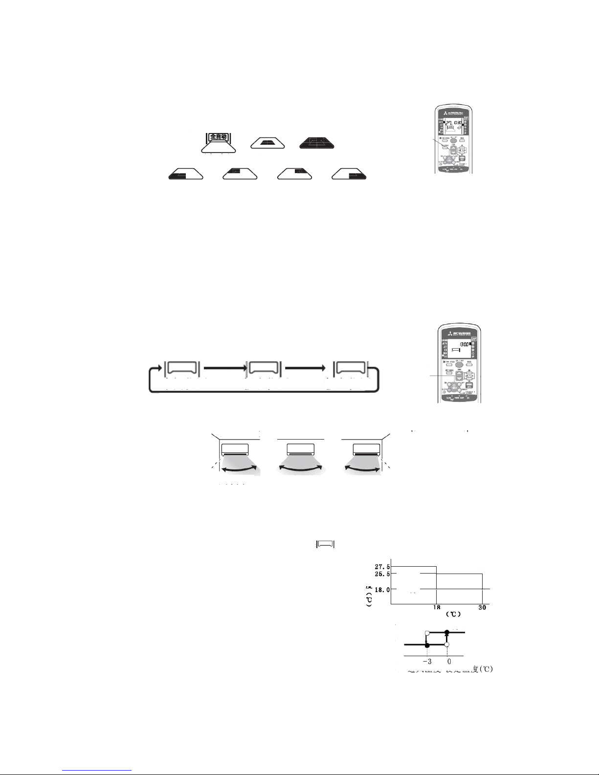
4.14 Air direction regulation:
(1) Operation method:
● Step 1: Press the ON/OFF button to run the air conditioner;
② Step 2: Press the Up/Down AIR FLOW button, as shown in the figure
below, to regulate the up/down direction of the vertical flap;
(Up/down swing) (Warm Feet)
③ Step 3: Press the Left/Right AIR FLOW button, as shown in the figure below, to regulate
the left/right air direction of the horizontal flap:
(2) Notes:
① Cool Air Shower (for cooling only): Through air direction regulation, cool air can be
blown everywhere in the room;
② Warm Feet (for heating only): Through air direction regulation, warm air can be even
blown to the bottom of feet;
(3) Use suggestions:
① Avoid directly blowing to the body for a long time;
② During cooling and drying, the up/down air direction is set to to prevent too
much cool air from going down;
③ During heating, the up/down air direction is set to to prevent too much warm
air from going up.
(4) Notes:
① When the Heating mode is enabled (that is, the heating operation begins), in order to
prevent cool air from blowing, the flap will move to the level position, in which case, the
air direction can’t be set. When warm air begins to blow, the air flap will be restored to
the set position, in which case, the air direction can be set.
② During the heating operation, when the room temperature is higher than the set
temperature, or during the defrosting operation, when the flap is at the level position, the
air direction can’t be set. The air direction can be set only when warm air begins to blow.
③ In the Cool Air Shower or Warm Feet mode, the horizontal flap will be at the level
position.
④ In the Cooling or Drying mode, avoid blowing downwards for a long time, otherwise,
condensation may appear on the air outlet grille and drip down;
⑤ Never attempt to regulate the air flap or regulating port manually, otherwise, the control
angle may change and the flap can’t be fully closed.
⑥ Flap memorizing function (stop of flap): When the flap is swinging, press the AIR
FLOW (Up/Down or Left/Right) button once, it will stop at that angle. As this angle is
memorized in the microcomputer, the flap will automatically operate at the same angle
next time the machine is started.
Power
Save
Up/Down
Left/Right
(Swing stops) (Cool Air Shower)
(Swing stops) (Leftmost) (Left) (Level) (Right)
(Left/right swing) (Fixed point) (Wide-angle) (Rightmost)
- 22 -
4.15 Area setting:
(1) The area setting function is used to regulate the indoor air and the air in the specific area in
the room.
(2) Operation method: When the air conditioner is running, press the AREA
button, as needed, to switch to the desired area.
(3) The area indications are as follows:
(Bottom left) (Top left) (Top right) (Bottom right)
(4) Cancelation: Press the Up/Down or Left/Right button to regulate the air direction.
(5) Notes:
① In the AUTO mode, the HI POWER and JET modes are not supported;
② After the Area setting is canceled, when the air conditioner is started again, the air
direction before the Area setting will be displayed.
4.16 Installation location setting:
(1) The installation location setting function is used to consider the installation location of air
conditioner and regulate the maximum space of the left/right air flow.
(2) Operation method:
① Switch on the air conditioner and let it stay in the stop mode;
If it is running, press the ON/OFF button to stop;
② Press and hold both the Up/Down and Left/Right buttons for over 5 seconds, and the
installation location will flash on the display;
③ Press the Left/Right button to regulate to the desired position;
whenever the Left/Right button is pressed, the displaying changes in
the following order:
④ Within 1 minute, press the ON/OFF button again to send a signal to
the air conditioner and the air conditioner will memorize the installation location.
(3) The installation location and air direction range of the air conditioner are as follows:
(4) Notes:
① After the installation location is set again, even when the plug is unplugged, the air
conditioner will also memorize the installation location;
② During operation, the installation location can’t be set;
③ After the installation location is set, if the air conditioner is reset or the batteries are
replaced, the remote controller will display , i.e. the installation location
memorized by the air conditioner.
4.17 Outline of automatic operation:
(1) Determination of operating mode:
After the indoor and outdoor fans operate at the 2nd speed
and 4th speed respectively for 20 seconds, the system will
check the room temperature, humidity and outdoor
temperature to automatically select the cooling, heating or
drying mode and the room temperature compensation
value, and operate automatically. (Note: Here, the vertical
flap stops at the level position and the horizontal flap
stops at the central position.)
(2) The system checks the temperature every hour after the
operation begins. When the operating mode is judged to be different from the previous one,
the operating mode will be changed;
Area
setting
(Central)
(Central)
(Full)
Area
setting
Press and
hold both
buttons
for 5 sec.
Central
Rightmost
Lefttmost
(About 30° from front
direction)
(About 30° from front
direction)
Central
Left
Right
Right
Left
Air direction
range
Cooling
Drying
Heating
Area A
Room
temp
Judgement
conditon
forArea A
Heating
Cooling
Air inlet temp. – set temp.
Outdoor temp.
- 23 -
(3) If the air conditioner is started again within 1 hour after the automatic operation stops, or it is
converted to automatic operation in the heating, cooling or drying mode, it will operate in the
previous mode.
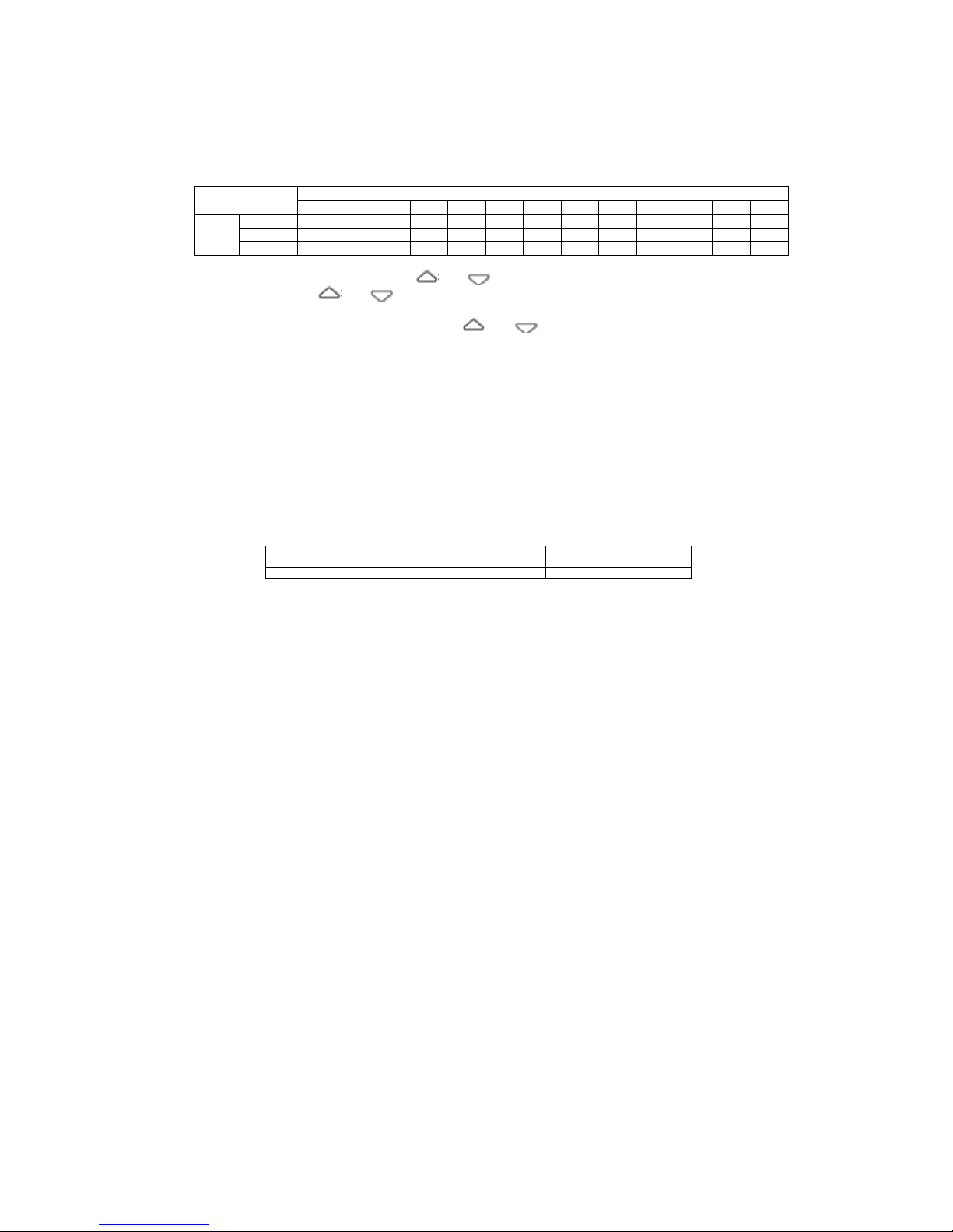
(4) The temperature can be set in the following range. The relationship between the signals of
the wireless remote controller and the set temperature is as follows:
Signals of wireless remote controller (displaying)
-6
-5
-4
-3
-2
-1 0 +1
+2
+3
+4
+5
+6
Set
temp
Cooling
18
19
20
21
22
23
24
25
26
27
28
29
30
Drying
18
19
20
21
22
23
24
25
26
27
28
29
30
Heating
20
21
22
23
24
25
26
27
28
29
30
31
32
(5) Operation of remote controller:
① In the AUTO mode, press the or button to regulate 6 levels of temperature;
② Each time the or button is pressed, the temperature will be switched in the
following order: -6 ~ -5 ~ -4 ~ -3 ~ -2 ~ -1 ~ ±0 ~ +1 ~ +2 ~ +3 ~ +4 ~ +5 ~ +6
③ When -6 or +6 is displayed, press the or button and the displaying will not
change;
④ The set temperature of ±0 in AUTO mode is: Cooling 24℃, Heating 26 ℃, Drying
24℃.
4.18 Outline of drying operation:
(1) Judgment of operation state:
① After the indoor and outdoor fans run at the 2nd speed and 3rd speed respectively for 20
minutes. the system checks the room temperature (Tai) and outdoor temperature (Th0-A)
to determine the operation state. (Note: Here, the vertical flap stops at the level position
and the horizontal flap stops at the central position.)
② The system checks the temperature every hour after the operation begins. When the
operating mode is judged to be different from the previous one, the operating mode will
be changed.
③ Judgment of operating mode:
Tai and TS (setting correction temperature), Th0-A relationship
Operating mode
Tai > TS-3 or Th0-A ≥ 19℃
Slightly cool heating & drying
Tai ≤ TS-3 or Th0-A < 19℃
Slightly warm heating & drying
(2) Notes:
① After the operating mode is judged, the system decides the running range according to
the room temperature and setting correction temperature every 5 minutes;
② Slightly cool heating & drying includes four running ranges, all of which are cooling
operations;
③ Slightly warm heating & drying includes four running ranges, in which three are cooling
operations and one is heating operation.
4.19 Outline of defrosting operation:
(1) Beginning conditions:
Case 1 (The defrosting running begins when all of the following conditions are met):
① After the heating begins and the defrosting ends, the accumulated running time of the
compressor exceeds 45 minutes;
② The outdoor heat exchanger sensor (Th0-R) meets one of the following conditions:
A) Accumulated running time of compressor < 150 minutes, Th0-R ≤ -5℃;
B) Accumulated running time of compressor ≥ 150 minutes, Th0-R ≤ -3.5℃;
③ The outdoor heat exchanger sensor (Th0-R) and the outdoor air temp. sensor (Th0-A)
meet one of the following conditions:
A) When outdoor air temp. sensor Th0-A ≥ 0℃:
Accumulated running time of compressor < 150 minutes, (Th0-A) - (Th0-R) ≥ 7.0;
B) When outdoor air temp. sensor Th0-A ≥ 0℃:
Accumulated running time of compressor ≥ 150 minutes, (Th0-A) - (Th0-R) ≥ 4.0;
C) When outdoor air temp. sensor -15℃ ≤Th0-A < 0℃:
Accumulated running time of compressor < 150 minutes, (Th0-A) - (Th0-R) ≥ 4/15 *
(Th0-A) + 7;
D) When outdoor air temp. sensor -15℃ ≤ Th0-A < 0℃:
Accumulated running time of compressor ≥ 150 minutes, (Th0-A) - (Th0-R) ≥ 4/15 *
(Th0-A) + 6;
E) When outdoor air temp. sensor Th0-A < -15℃: (Th0-A) - (Th0-R) ≥ -5.0;
④ The compressor runs for over 7 minutes continuously.
Case 2: Low load running (The defrosting running begins when all of the following conditions
are met):
① After the heating begins and the defrosting ends, the accumulated running time of the
compressor is 45 minutes with air flow controlled;
- 24 -
② The outdoor heat exchanger sensor (Th0-R) meets one of the following conditions:
A) When the actual rotate speed of the compressor N ≥ 62 rps: Th0-R ≤ -5℃;
B) When the actual rotate speed of the compressor N < 62 rps: Th0-R ≤ -4℃;
③ Outdoor air temp. sensor (Th0-A): Th0-A ≤ 3℃;
④ The compressor runs for over 7 minutes continuously.
(2) Ending conditions:
135 seconds after the system is switched to the defrosting mode, the defrosting running is
canceled when one of the following conditions is met:
① Outdoor heat exchanger sensor (Th0-R): Th0-R ≥ 13℃;
② The elapsed time of defrosting running is 15±0.5 min.
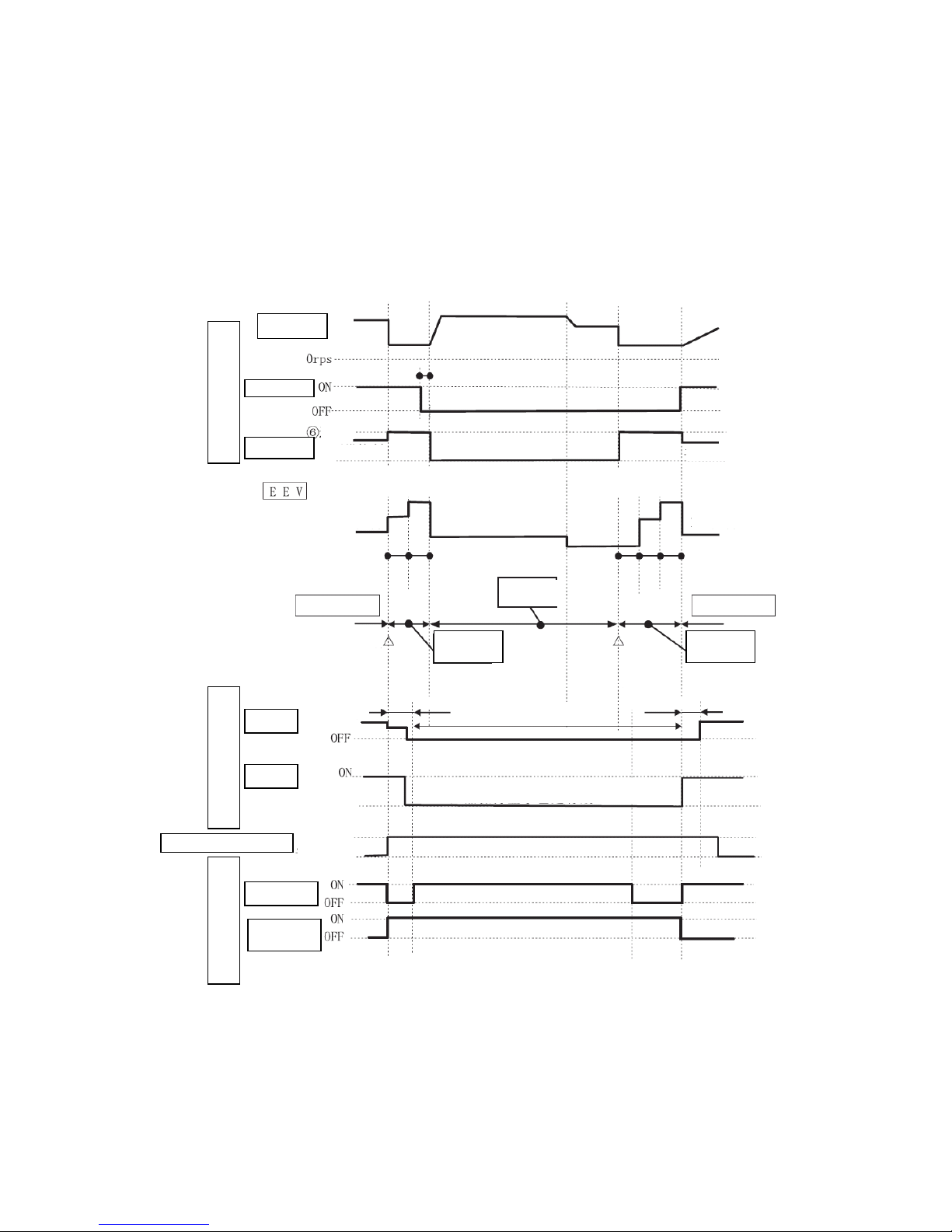
(3) Operation time pattern of various functional parts in defrosting control:
Defrosting
Compressor
4-way valve
Outdoor fan
Operation of outdoor
functional parts
5 sec.
speed
Usual control
Usual control
Enter
EEV openng
EEV control
EEV openng
EEV control
End running
EEV openng
Usual heating
Usual heating
Defrosting
running state
Beginning
conditions met
Enter defrosting
running
Ending
conditions
met
End defrosting
running
Heat-retaining
Heat-retaining
Heat-retaining
ineffective
Indoor fan
RUN lamp
Operation of indoor
functional parts
Indoor → outdoor
communication
Verhical/horizontal flap
Response
Flahsing
(heat-retaining)
Control
Set position
In the defrosting control, even when the compressor
displays OFF, the heat-retaining displaying is effective.
Singnal of
compressor
Defrosting
singnal
- 25 -
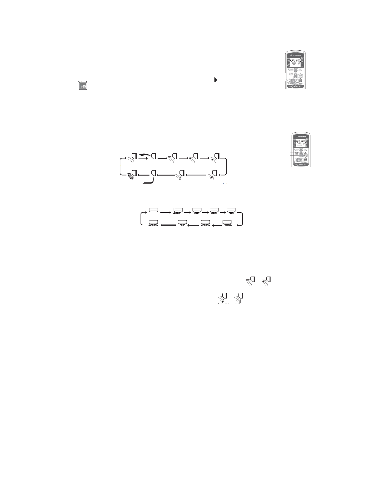
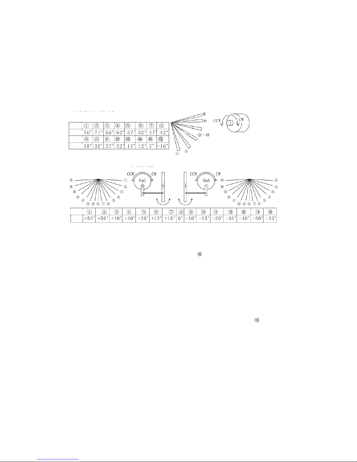
4.20 Outline of vertical and horizontal flaps control:
(1) Overview:
Sm1: Vertical flap (mounted on the right side when you face the appliance);
Sm2: Left horizontal flap (mounted on the left side when you face the appliance);
Sm3: Right horizontal flap (mounted on the right side when you face the appliance);
(2) Vertical flap Sm1:
The level set is 0℃.
(3) Horizontal flaps Sm2 and Sm3:
(4) Reference position control:
① Beginning condition: This control is executed only when the air conditioner begins to run.
It is not executed when the operating mode is switched and the flap mode is changed.
② Control: This control ends when the vertical flap Sm1 moves to position ① and the
horizontal flaps Sm2 and Sm3 move to position . The flaps stop at the position set with
the remote controller or the preset position memorized.
(4) Control of vertical flap and horizontal flaps at the start of heating, stop of heating and for
defrosting:
To avoid blowing cool air during heating before the indoor heat exchanger is fully warmed.
① Beginning condition (when one of the following conditions is met):
A) The indoor running mode is switched from a mode other than Heating to the Heating
mode, and the temperature measured by the indoor heat exchanger sensor is < 28℃;
B) During the Heating mode, the compressor displays OFF;
C) During the Heating mode, the defrosting signal is received.
② Control: This control ends when the vertical flap Sm1 moves to position and the
horizontal flaps Sm2 and Sm3 move to position ⑧.
③ Ending conditions (when one of the following conditions is met):
A) The indoor running mode is switched from a mode other than Heating to the Heating
mode, and the temperature measured by the indoor heat exchanger sensor is ≥ 28℃;
B) In the Heating mode, the compressor is changed from OFF to ON, and the
temperature measured by the indoor heat exchanger sensor is ≥ 28℃;
C) In the Heating mode, the defrosting signal is canceled, and the temperature measured
by the indoor heat exchanger sensor is ≥ 28℃;
D) When this control is canceled, the flap position before the control is restored.
④ Notes:
A) This control is not executed in the JIS mode;
B) This control is not executed when the temperature measured by the indoor heat
exchanger sensor is approximately below -28℃ (disconnection of sensor).
Position
Position
Angle
Angle
Relationship between rotation direction
of motor and state of vertical flap
Vertical flap closed → CCW of motor
Vertical flap opened → CW of motor
Position
Angle
For left flap
For right flap
Wide-angle
Wide-angle
Fixed point direction

- 26 -
4.21 Outline of electronic expansion valve (EEV) control:
(1) Overview:
① Initial control: When the power is ON and the reference position is determined, the EEV opening is
widened within 5 minutes to let the refrigerant return, thus makes the low pressure rise easily and
avoid misdiagnosis of insufficient refrigerant and poor EEV operation as the low pressure can’t rise
after decline;
② Open loop control: After the initial control, when the temperature measured by the sensor, etc. are
unstable, the EEV opening is set according to the balance of the compressor;
③ Area control: During quasi-steady running and steady running, the EEV opening is set according to
the extent of over heat of exhaust, mainly aiming at the measure for the deviation due to open loop
control;
④ Stop control: The EEV opening is set according to the stop control;
⑤ Negative pressure countermeasure control: When the mode is switched from a mode other than
Heating to the Heating mode, the compressor is changed from OFF to ON, and the outdoor
temperature is too low (temperature measured by discharge pipe sensor (Th0-D) - temperature
measured by outdoor air temp. sensor (Th0-A) < 10℃), this control is executed for 8 minutes to
avoid negative pressure risk;
⑥ Throttle correction control of cooling & drying: Five minutes after the area control, when the actual
rotate speed of the compressor is below 24 rps and the temperature measured by the outdoor air
temp. sensor (Th0-A) meets the condition 25℃≤ Th0-A < 38℃ and the temperature measured by
the indoor heat exchanger sensor (Th1-RX) is above 10℃, this control is executed to increase the
latent heat capacity in cooling;
⑦ Condensation prevention control: When the actual rotate speed of the compressor is above 32 rps
and the value measured by the humidity sensor (HS) is above 68% for 30 minutes continuously, this
control is executed to make the actual rotate speed of the compressor reduce to below 32 rps or
make the value measured by HS reduce to below 63%.
(2) Priority of various EEV controls:
Stop control > Defrosting control > Indoor issued fixed opening control > Initial control > Protective
control > Open loop control and area control
(3) Except the special situations such as reference position control, etc., others are controlled within the
pulse range of 41-47.
4.22 Outline of compressor control:
(1) Overview of ON/OFF of cooling and heating running:
① When the outdoor running mode is Cooling or Heating, the compressor has stopped for over 3
minutes, and the compressor running signal from the indoor unit is received, the compressor will be
turned on;
② When the compressor is ON, the rotate speed of the compressor is fuzzily calculated using the
temperature of the indoor inlet air, the temperature set with the remote controller, the setting
correction temperature, etc., and the outdoor unit sends the compressor ON signal, the value of
fuzzy calculation, the actual rotate speed, etc. to the indoor unit;
③ When the outdoor running mode is Cooling or Heating, the compressor has run for over 5 minutes,
and the compressor stop signal from the indoor unit is received, the compressor will be turned off;
④ When the compressor is OFF, the outdoor unit sends the compressor OFF signal, the value of fuzzy
calculation, the actual rotate speed, etc. to the indoor unit;
⑤ In defrosting control, the compressor OFF conditions are not judged.
(2) Running range: 20-120 rps (varying depending on the model).
(3) In order to prevent the oil level of the compressor from falling and ensure that oil is supplied to the
pump of the compressor normally, enable the protection against temporary rise of rotate speed of
compressor.
(4) In order to guarantee the pressure difference for switching the 4-way valve, enable the low load for
temporary rise of rotate speed of compressor.
(5) With respect to the change rate of the actual rotate speed of the compressor, the instructed rotate speed
from the outdoor inverter to the compressor and the temperature measured by the outdoor heat
exchanger sensor (during cooling) or the temperature measured by the indoor heat exchanger sensor
(during heating) should be observed to decide the rise/fall speed of the compressor (2 rps, 1/2 rps) and
finally make the compressor operate in the appropriate working state.
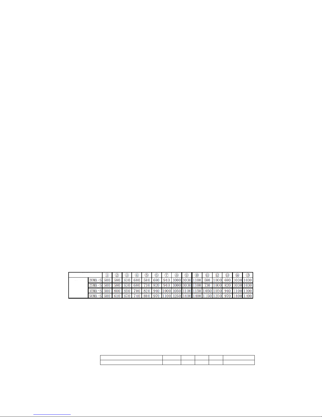
4.23 Outline of outdoor fan control:
(1) The settings of rotate speed of the outdoor fan are as follows:
Speed position
① ② ③ ④ ⑤ ⑥ ⑦
⑧
Rotate speed
(rpm)
20MA-S
150
240
570
630
720
780
840
920
25 MA-S
150
240
570
630
720
780
840
920
35 MA-S
150
240
570
640
750
840
900
950
50 MA-S
150
290
520
650
700
750
800
850
- 27 -
(2) Priority of rotate speed control:
Error response control > Outdoor fan control in compressor soft start control > Outdoor fan
control in defrosting control > Outdoor fan control/indoor forcing outdoor fan running
control in stop mode > Outdoor fan control at start > Outdoor fan control at the low outdoor
temperature in cooling > Outdoor fan control under overload in cooling > Delayed speed
position switching > Outdoor fan control under overload in heating > Speed position control
(3) Error response control:
When the outdoor fan runs at a speed below 75 rpm for over 30 seconds, the inverter will
immediately stop output to the fan and indicate results of self-diagnosis; if this occurs 3
times, it will send the error code to the indoor unit; if the speed exceeds 75 rpm once before
the 3 times, recount will be conducted.
(4) The minimum rotate speed of the outdoor fan in the compressor soft start control is speed
④.
(5) In the defrosting control, the rotate speed of the outdoor fan is OFF or speed ⑥.
(6) Outdoor fan control in the stop mode:
When the actual rotate speed of the compressor is 0, the outdoor fan continues to run at speed
③ for 1 minute or 2 minutes and 55 seconds and then stop.
(7) Indoor forced running control:
When the outdoor fan running start signal is received from the indoor unit, the operation at
the fan speed received will begin, and this control is unrelated to the running mode,
compressor instruction and protection stop (except outdoor fan error, low voltage). This
control is canceled when the outdoor fan running cancel signal is received from the indoor
unit.
(8) At start, the outdoor fan operates according to the speed position control; when the
compressor is started and in the ON state in the cooling mode and the outdoor temperature is
below 22℃, it will run at speed ② or ① for 30 seconds.
(9) Outdoor fan control of low outdoor temperature in cooling, overload in cooling, low outdoor
temperature in heating and overload in heating:
① In the cooling or heating mode, when the compressor is in the ON state and the
temperature measured by the outdoor air temp. sensor meets the control conditions, this
control will begin.
② This control is canceled when either of the above conditions is not met.
③ According to the temperature measured by the outdoor heat exchanger liquid pipe sensor
and the temperature measured by the outdoor air temp. sensor, the rotate speed of the
outdoor fan is decreased (to as low as speed ② or ①) or increased (up to speed ⑧).
(10) Delayed speed position switching control:
When the outdoor fan is changed from a high speed position to a low one, the switching is
generally delayed for 60 seconds. If it is changed to a high speed position within 60 seconds,
the delay will be canceled and it is converted to the high speed position immediately. If the
outdoor fan is changed to OFF, there will be no delay and it will stop immediately.
(11) The speed position control is generally between speed ③ and ⑧.
4.24 Outline of indoor fan control:
(1) The settings of rotate speed of the indoor fan are as follows:
(2) Priority of rotate speed switching:
HI POWER > AUTO/HI/ME/LO
(3) Error response control:
When the indoor fan runs at a speed below 75 rpm for over 30 seconds, the air conditioner
will fully stop to indicate the results of self-diagnosis.
(4) When the indoor fan is started and runs for 1 second under the initial voltage at the speed of
300 rpm, the system will compare with the signal from the fan to correct the rotate speed to
the determined one.
(5) Rate of rotate speed adjustment: 80 rpm for increase and 10 rpm for decrease.
(6) The speed positions corresponding to the fan speeds are as follows:
Air flow switching
AUTO
HI
ME
LO
HI POWER
Speed position of indoor fan
⑤ ⑥ ⑤ ④ ⑦
Speed position
Rotate
speed
(rpm)
 Loading...