

Mitsubishi Heavy Industries SRC10CDV-1, SRK13CDV-1, SRK10CDV-4, SRC10CDV-4, SRC13CDV-1 Technical Handbook
...
-
3
-
2004 ROOM AIR-CONDITIONING
TECHNICAL HANDBOOK
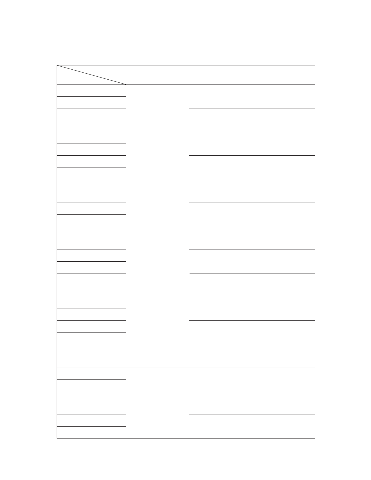
TABLE OF CONTENTS
SRK10CDV-1
SRC10CDV-1
SRK10CDV-4
SRC10CDV-4
SRK13CDV-1
SRC13CDV-1
SRK13CDV-4
SRC13CDV-4
SRK06CC-1
SRC06CC-1
SRK06CC-4
SRC06CC-4
SRK07CC-1
SRC07CC-1
SRK07CC-4
SRC07CC-4
SRK09CC-1
SRC09CC-1
SRK09CC-4
SRC09CC-4
SRK12CC-1
SRC12CC-1
SRK12CC-4
SRC12CC-4
SRK50A
SRC50CA
SRK56A
SRC56CA
SRK56A-4
SRC56CA-4
1
31
63
90
90
98
98
108
108
116
116
124
124
132
132
142
150
150
Technical manual
Item
Models
Parts list
Recommendable
spare parts price list
*
Models with “-4” have the “HEAVY DUTY” logo added on the front lower rightside.
-
1
-
CONTENTS
1. GENERAL INFORMATION .............................................................................. 2
1.1 Specific features ....................................................................................... 2
1.2 How to read the model name ................................................................... 2
2. SELECTION DATA .......................................................................................... 3
2.1 Specifications ........................................................................................... 3
2.2 Range of usage & limitations .................................................................. 6
2.3 Exterior dimensions ................................................................................. 6
2.4 Piping system ........................................................................................... 8
2.5 Selection chart .......................................................................................... 9
3. ELECTRICAL DATA ........................................................................................ 10
3.1 Electrical wiring ........................................................................................ 10
4. OUTLINE OF OPERATION CONTROL BY MICROCOMPUTER .................. 12
5. APPLICATION DATA ....................................................................................... 19
5.1 Selection of location for installation ....................................................... 20
5.2 Installation of indoor unit......................................................................... 21
5.3 Installation of outdoor unit ...................................................................... 23
5.4 Refrigerant piping ..................................................................................... 23
5.5 Test run ...................................................................................................... 25
5.6 Precautions for wireless remote controller installation and
operation ................................................................................................... 25
6. MAINTENANCE DATA .................................................................................... 26
6.1 Trouble shooting ....................................................................................... 26
6.2 Servicing.................................................................................................... 29
TECHNICAL MANUAL
MODELS SRK10CDV-1 SRK10CDV-4 SRK13CDV-1 SRK13CDV-4
-
2
-
1 GENERAL INFORMATION
1.1 Specific features
The “Mitsubishi Daiya” room air-conditioner: SRK series are of split and wall mounted type and the unit consists of indoor unit and
outdoor unit with refrigerant precharged in factory. The indoor unit is composed of room air cooling equipment with operation control
switch and the outdoor unit is composed of condensing unit with compressor.
(1) Remote control flap
The flap can be automatically controlled by operating wireless remote controller.
¡ Air scroll: Flap operation is automatically control.
¡ Swing: This will swing the flap up and down.
¡ Memory flap: Once the flap position is set, the unit memorizes the position and continues to operate at the same position from
the next time.
(2) Automatic Operation
When the remote control switch is set on “auto( ) ”, it will either automatically decide operation mode such as cooling and thermal
dry, or operate in the operation mode before it has been turned to automatic control.
(3) Self diagnosis function
¡ We are constantly trying to do better service to our customers by installing such judges that show abnormality of operation as
follows.
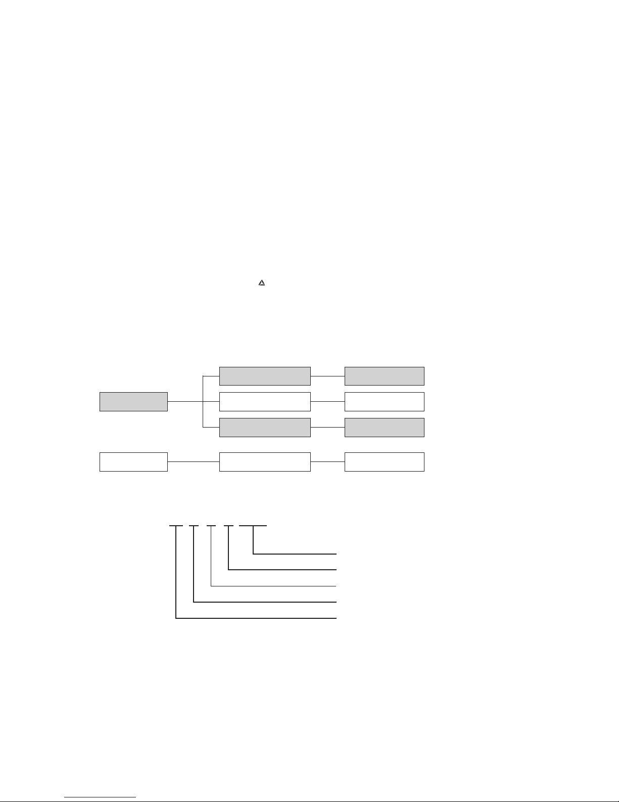
1.2 How to read the model name
Example : SR K 10 C DV - 1
Series No.
Cooling only type
Product capacity
Wall mounted type
Split type room air conditioner
Abnormality of room
temperature thermistor.
TIMER lamp is
light up.
RUN lamp is flashing.
(1 Times/ 8sec.)
RUN lamp is flashing.
(2 Times/ 8sec.)
Abnormality of heat
exchanger thermistor.
Abnormality of indoor
fan motor.
RUN lamp is flashing.
(6 Times/ 8sec.)
t
t
t
Abnormality of outdoor
unit.
RUN lamp is light
up.
TIMER lamp is flashing.
(2 Times/ 8sec.)
t
No lamps will flashing
when the unit is operating.
}
-
3
-
2 SELECTION DATA
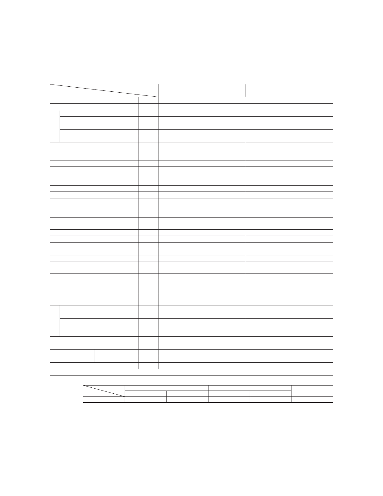
2.1 Specifications
Model SRK10CDV-1, -4 (Indoor unit)
SRC10CDV-1, -4 (Outdoor unit)
(2) The operation data are applied to the 220 V districts respectively.
(3) The refrigerant quantity to be charged includes the refrigerant in 7.5 m connecting piping.
(Purging is not required even in the short piping.)
If the piping length is longer, when it is less than 10 m, add 10 g refrigerant per meter and when it is 10 to 15 m, add 30 g refrigerant per meter.
(4) Expressed in sound pressure level.
Notes (1) The data are measured at the following conditions.
Item
Model
SRK10CDV-1, -4 SRC10CDV-1, -4
Cooling capacity
(1)
W 2638
Power source 1 Phase, 220V, 50Hz
Cooling input kW 0.803
Running current (Cooling) A 4.2
Inrush current A 18.1
COP (In cooling) 3.29
Noise level
(4)
dB (A) 39 46
Exterior dimensions
mm 250 × 815 × 247 540 × 720 × 290
Height × Width × Depth
Color Cool white Stucco white
Net weight kg 9.0 32
Refrigerant equipment
–
RMC201A002
Compressor types & Q’ty
Motor kW – 0.75
Starting method – Line starting
Heat exchanger Louver fins & tubing
Refrigerant control Capillary tubes
Refrigerant
(3)
kg R22 0.75 (Pre-Charged up to the piping length of 7.5m)
Refrigerant oil R 0.35 (ATMOS M60 or SUNISO 4GDID)
Air handling equipment
Tangential fan × 1 Propeller fan × 1
Fan type & Q’ty
Motor W 14 15
Air flow (at High) CMM 8.5 30.0
Air filter, Q’ty Polypropylene net (washable) × 2–
Shock & vibration absorber – Cushion rubber (for compressor)
Electric heater ––
Operation control
Wireless-Remote controller –
Operation switch
Room temperature control MC. Thermostat –
Pilot lamp RUN (Green), TIMER (Yellow),
–
HI POWER (Green), ECONO (Orange)
Safety equipment Frost protection,
Compressor overheat protection
Fan motor error protection
O.D mm (in) Liquid line: ø6.35 (1/4") Gas line: ø9.52 (3/8")
Connecting method Flare connecting
Attached length of piping Liquid line: 0.4 m
–
Gas line : 0.33 m
Insulation Necessary (Both sides)
Drain hose Connectable
Power source cord 2.5 m (3 cores with Earth)
Size × Core number 1.5 mm2 × 3 cores (Including earth cable)
Connecting method Terminal block (Screw fixing type)
Accessories (included) Mounting kit
Optional parts –
Connection
wiring
Operation
data
(1)
Refrigerant
piping
Item Indoor air temperature Outdoor air temperature
Standards
Operation DB WB DB WB
Cooling 27°C19°C35°C24°C ISO-T1, JIS C9612

-
4
-
(2) The operation data are applied to the 220 V districts respectively.
(3) The refrigerant quantity to be charged includes the refrigerant in 7.5 m connecting piping.
(Purging is not required even in the short piping.)
If the piping length is longer, when it is less than 10 m, add 10 g refrigerant per meter and when it is 10 to 15 m, add 30 g refrigerant per meter.
(4) Expressed in sound pressure level.
Notes (1) The data are measured at the following conditions.
Item
Model
SRK13CDV-1 SRC13CDV-1
Cooling capacity
(1)
W 3500
Power source 1 Phase, 220V, 50Hz
Cooling input kW 1.16
Running current (Cooling) A 6.1
Inrush current A 33.2
COP (In cooling) 3.28
Noise level
(4)
dB (A) 41 49
Exterior dimensions
mm 250 × 815 × 247 640 × 850 × 290
Height × Width × Depth
Color Cool white Stucco white
Net weight kg 9.0 40
Refrigerant equipment
–
RMC201A001
Compressor types & Q’ty
Motor kW – 1.3
Starting method – Line starting
Heat exchanger Louver fins & tubing
Refrigerant control Capillary tubes
Refrigerant
(3)
kg R22 1.2 (Pre-Charged up to the piping length of 7.5m)
Refrigerant oil R 0.48 (SUNISO 4GSD)
Air handling equipment
Tangential fan × 1 Propeller fan × 1
Fan type & Q’ty
Motor W 14 35
Air flow (at High) CMM 9.0 39.5
Air filter, Q’ty Polypropylene net (washable) × 2–
Shock & vibration absorber – Cushion rubber (for compressor)
Electric heater ––
Operation control
Wireless-Remote controller –
Operation switch
Room temperature control MC. Thermostat –
Pilot lamp RUN (Green), TIMER (Yellow),
–
HI POWER (Green), ECONO (Orange)
Safety equipment Frost protection,
Internal thermostat (for compressor)
Fan motor error protection
O.D mm (in) Liquid line: ø6.35 (1/4") Gas line: ø12.7 (1/2")
Connecting method Flare connecting
Attached length of piping Liquid line: 0.4 m
–
Gas line : 0.33 m
Insulation Necessary (Both sides)
Drain hose Connectable
Power source cord 2.5 m (3 cores with Earth)
Size × Core number 1.5 mm2 × 3 cores (Including earth cable)
Connecting method Terminal block (Screw fixing type)
Accessories (included) Mounting kit
Optional parts –
Connection
wiring
Operation
data
(1)
Refrigerant
piping
Item Indoor air temperature Outdoor air temperature
Standards
Operation DB WB DB WB
Cooling 27°C19°C35°C24°C ISO-T1, JIS C9612
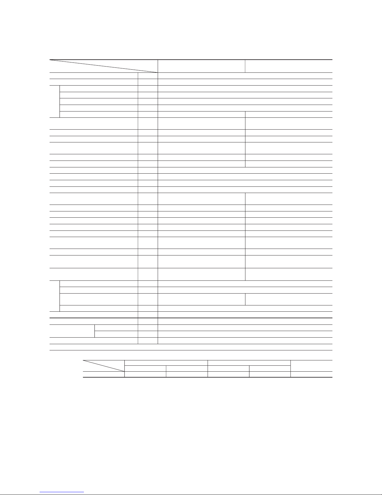
Model SRK13CDV-1 (Indoor unit)
SRC13CDV-1 (Outdoor unit)
-
5
-
(2) The operation data are applied to the 220 V districts respectively.
(3) The refrigerant quantity to be charged includes the refrigerant in 7.5 m connecting piping.
(Purging is not required even in the short piping.)
If the piping length is longer, when it is less than 10 m, add 10 g refrigerant per meter and when it is 10 to 15 m, add 30 g refrigerant per meter.
(4) Expressed in sound pressure level.
Notes (1) The data are measured at the following conditions.
Item
Model
SRK13CDV-4 SRC13CDV-4
Cooling capacity
(1)
W 3810
Power source 1 Phase, 220V, 50Hz
Cooling input kW 1.16
Running current (Cooling) A 6.1
Inrush current A 33.2
COP (In cooling) 3.28
Noise level
(4)
dB (A) 41 49
Exterior dimensions
mm 250 × 815 × 247 640 × 850 × 290
Height × Width × Depth
Color Cool white Stucco white
Net weight kg 9.0 40
Refrigerant equipment
–
RMC201A001
Compressor types & Q’ty
Motor kW – 1.3
Starting method – Line starting
Heat exchanger Louver fins & tubing
Refrigerant control Capillary tubes
Refrigerant
(3)
kg R22 1.2 (Pre-Charged up to the piping length of 7.5m)
Refrigerant oil R 0.48 (SUNISO 4GSD)
Air handling equipment
Tangential fan × 1 Propeller fan × 1
Fan type & Q’ty
Motor W 14 35
Air flow (at High) CMM 9.0 39.5
Air filter, Q’ty Polypropylene net (washable) × 2–
Shock & vibration absorber – Cushion rubber (for compressor)
Electric heater ––
Operation control
Wireless-Remote controller –
Operation switch
Room temperature control MC. Thermostat –
Pilot lamp RUN (Green), TIMER (Yellow),
–
HI POWER (Green), ECONO (Orange)
Safety equipment Frost protection,
Internal thermostat (for compressor)
Fan motor error protection
O.D mm (in) Liquid line: ø6.35 (1/4") Gas line: ø12.7 (1/2")
Connecting method Flare connecting
Attached length of piping Liquid line: 0.4 m
–
Gas line : 0.33 m
Insulation Necessary (Both sides)
Drain hose Connectable
Power source cord 2.5 m (3 cores with Earth)
Size × Core number 1.5 mm2 × 3 cores (Including earth cable)
Connecting method Terminal block (Screw fixing type)
Accessories (included) Mounting kit
Optional parts –
Connection
wiring
Operation
data
(1)
Refrigerant
piping
Item Indoor air temperature Outdoor air temperature
Standards
Operation DB WB DB WB
Cooling 27°C19°C35°C24°C ISO-T1, JIS C9612
Model SRK13CDV-4 (Indoor unit)
SRC13CDV-4 (Outdoor unit)
-
6
-
2.2 Range of usage & limitations
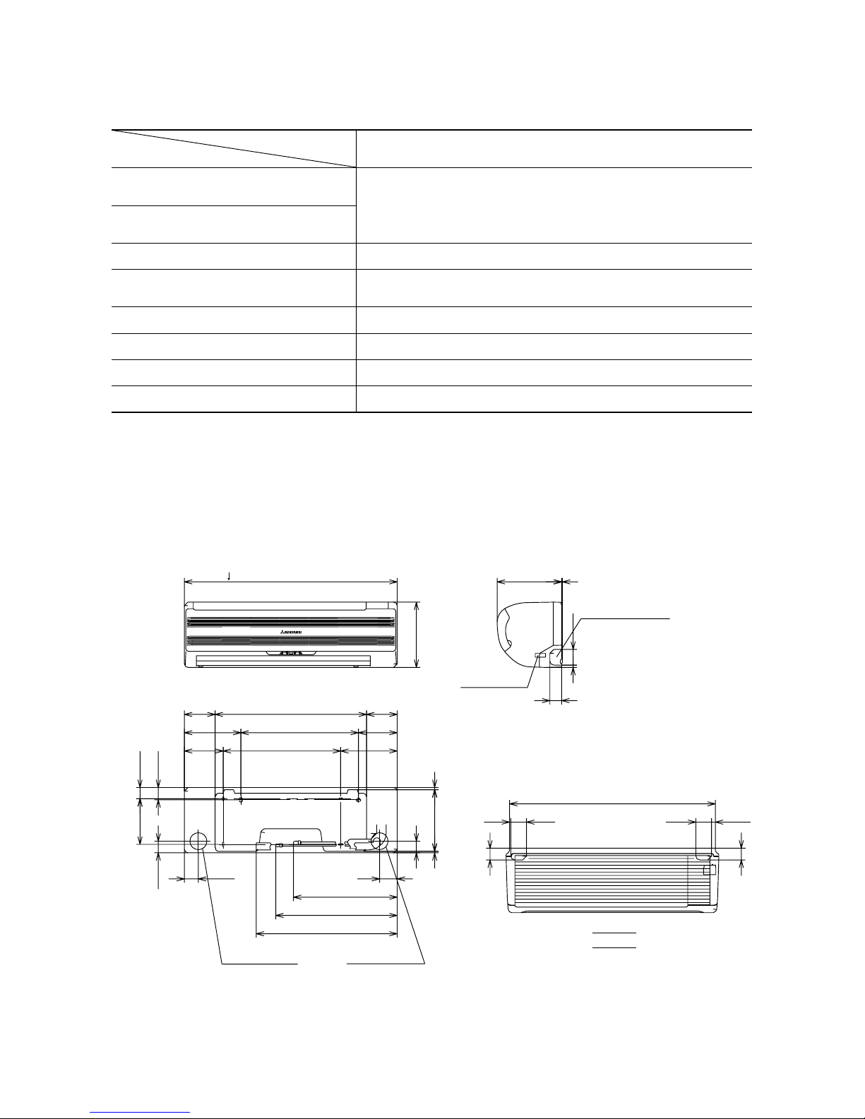
2.3 Exterior dimensions
Indoor return air temperature
(Upper, lower limits)
Refrigerant line (one way) length Max. 15m
All models
Refer to the selection chart
Power source voltage Rating ± 10%
Voltage at starting Min. 85% of rating
Frequency of ON-OFF cycle Max. 10 times/h
ON and OFF interval Max. 3 minutes
Outdoor air temperature
(Upper, lower limits)
Vertical height difference between
outdoor unit and indoor unit
Max. 5m (Outdoor unit is higher)
Max. 5m (Outdoor unit is lower)
Item
Models
(1) Indoor unit
Models SRK10CDV-1, 10CDV-4, 13CDV-1, 13CDV-4
Unit: mm
A
VIEW A
815
117.5
580 117.5
247
4.5
4.5
4.5
3
560
788
60 14.5
60
9
148.5
216.5216.5
8.2
44.5
236.1
5.7
450
450
67.5
42.7
47.2
175
44.5
216.5216.5
148.5
53.5
250
Piping for Gas
Terminal block
Piping hole right (left)
Drain hose 540 (ø16)
Piping for Liquid 465.1 (ø6.35)
Piping hole (ø65)
Piping hole (ø65)
( )
10: ø9.52
13: ø12.7
397.1
-
7
-
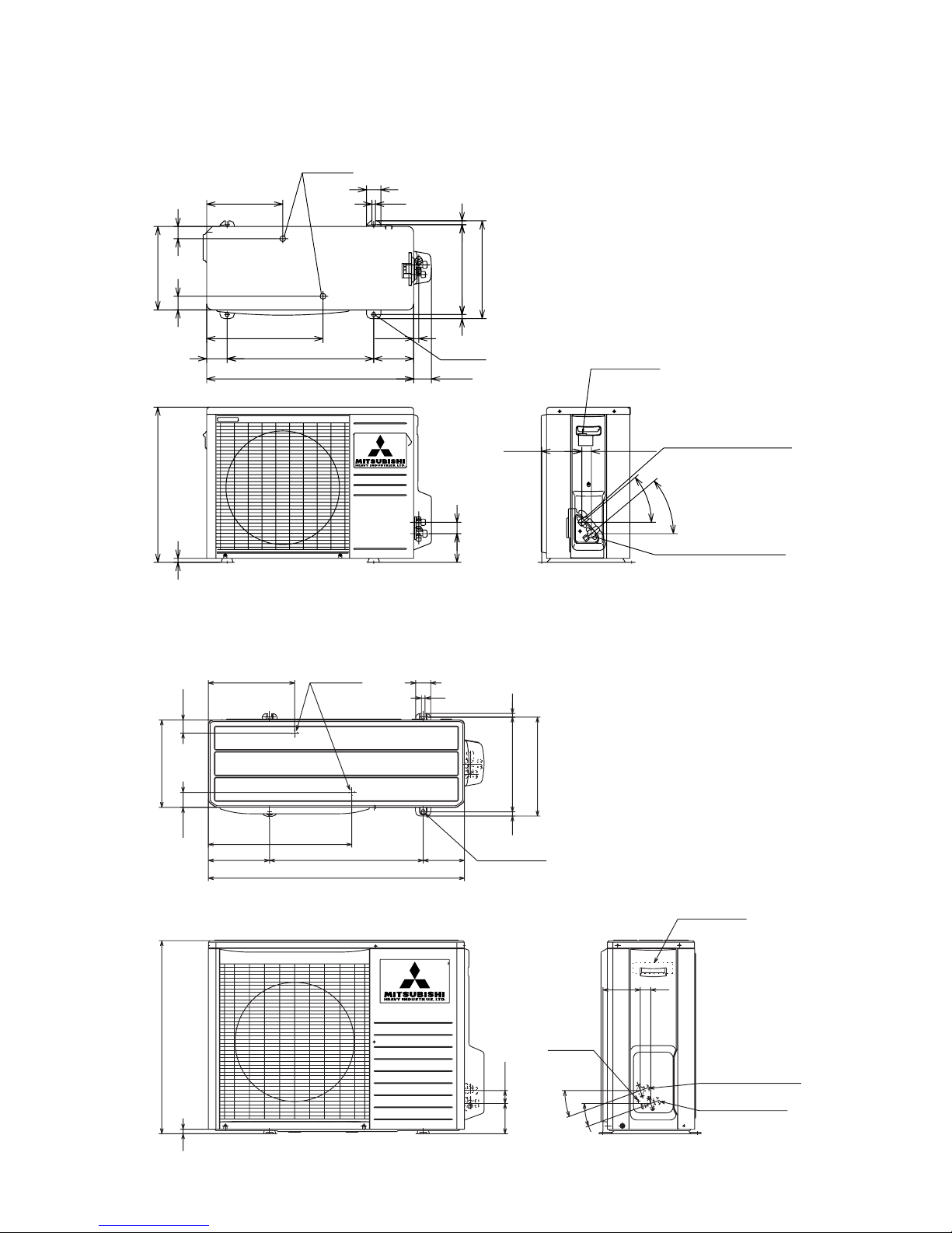
(2) Outdoor unit
Models SRC10CDV-1, 10CDV-4
Drain hole
286.4
12
50
290
49.6
43.5
850
203.1
510 136.9
476
Elogated hole
(2-12 x16)
314
12
328
Terminal block
Service valve (Liquid)
ø6.35 (1/4'')
Service valve (Gas)
ø12.7 (1/2'')
Ground
terminal
124
34.6
20˚
20˚
42.7
100.3
15
640
14
Unit: mm
Model SRC13CDV-1, 13CDV-4
Unit: mm
290
540
14.4
47.4 42.6
264.5
71
404.5
510
720
17.8
Drain holes
50
12
39.7
99.9
340
312.5
13.5
14
139
2-16 x12
61.9
139.3 33.3
Flare connecting ø6.35 (1/4")
Service valve (Liquid)
40°
40°
Flare connecting ø9.52 (3/8")
Service valve (Gas)
Terminal block
-
8
-
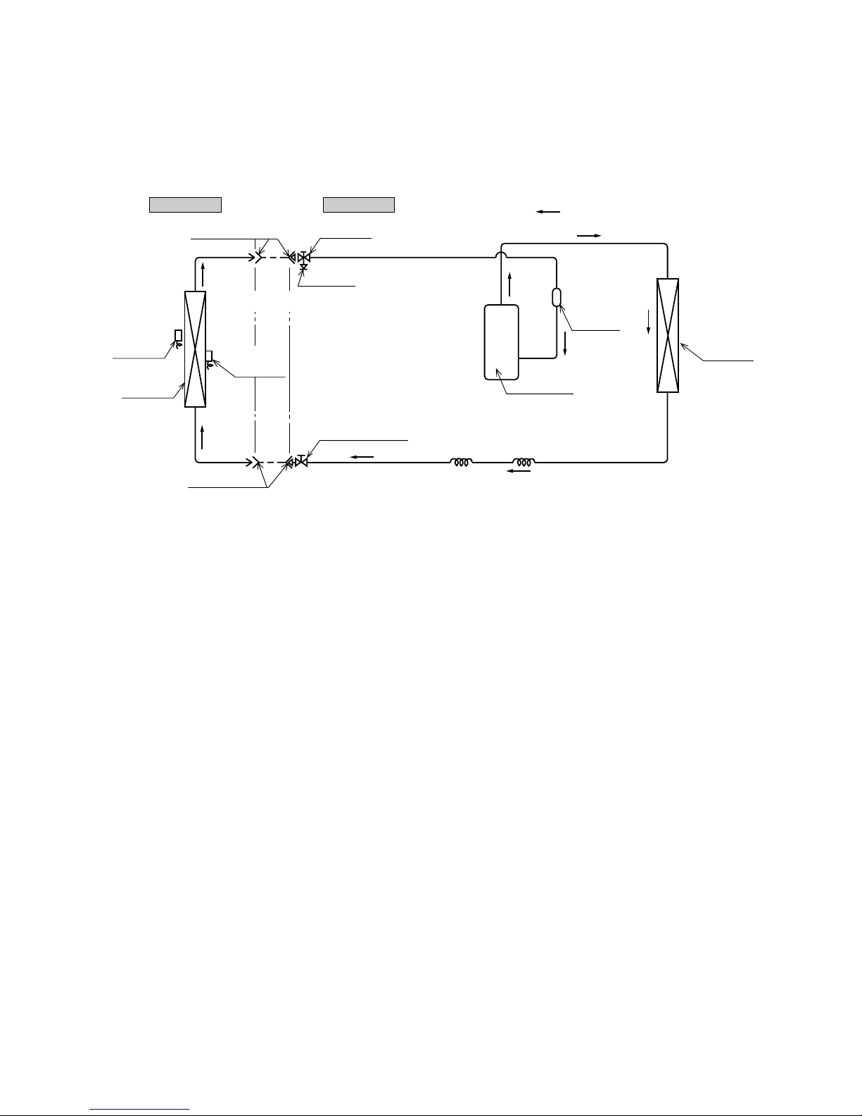
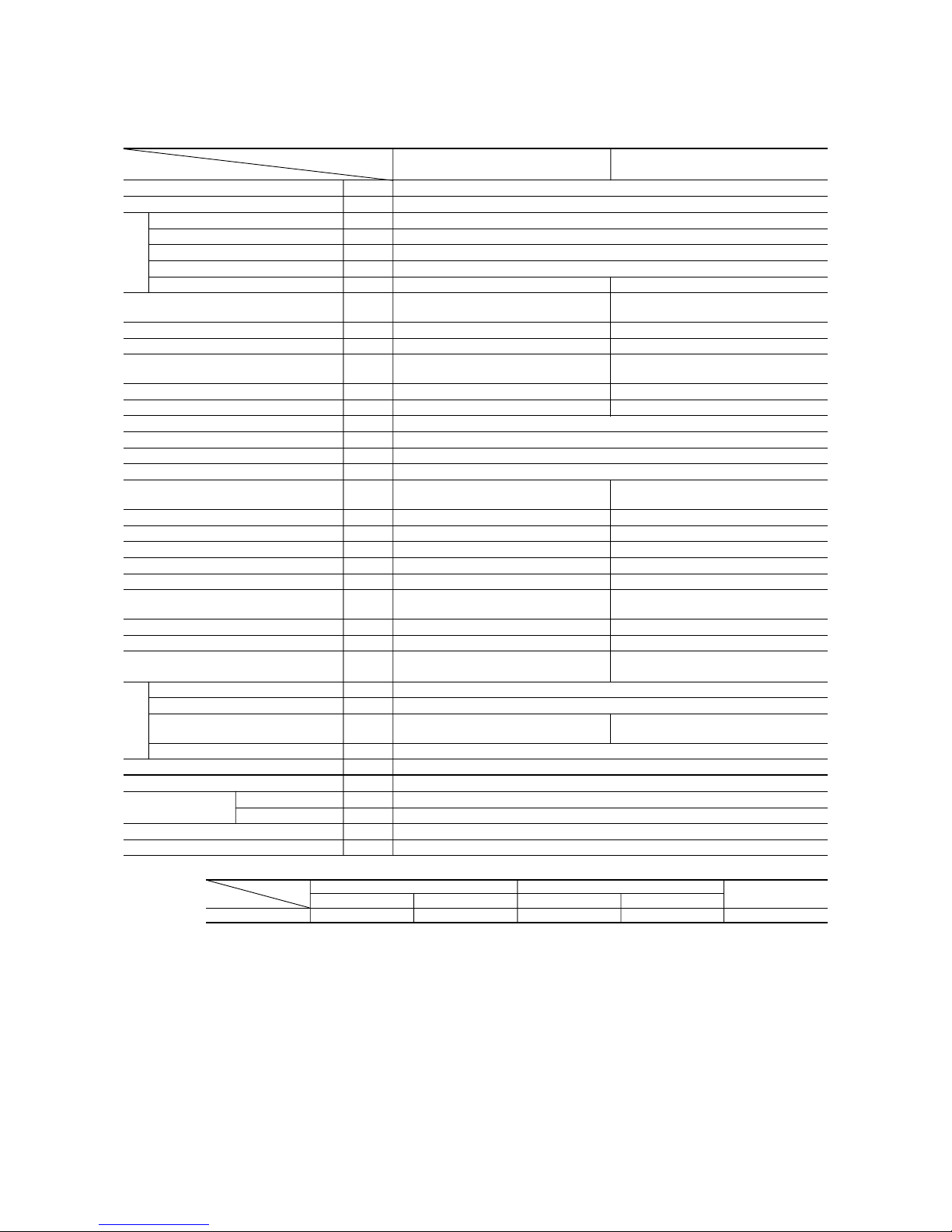
2.4 Piping system
Models SRK10CDV-1, 10CDV-4, 13CDV-1, 13CDV-4
Outdoor unitIndoor unit
Room temp.
thermistor
Heat
exchanger
Flare connecting
Heat
exchanger
thermistor
Piping
(Liquid)
ø6.35
Check joint
Service valve (Liquid)
Flare connecting
Cooling cycle
Heat
exchanger
Compressor
Capillary tube
Accumulator
Service valve
(Gas)
Capillary tube
( )
Piping
(Gas)
10 : ø9.52
13 : ø12.7
-
9
-
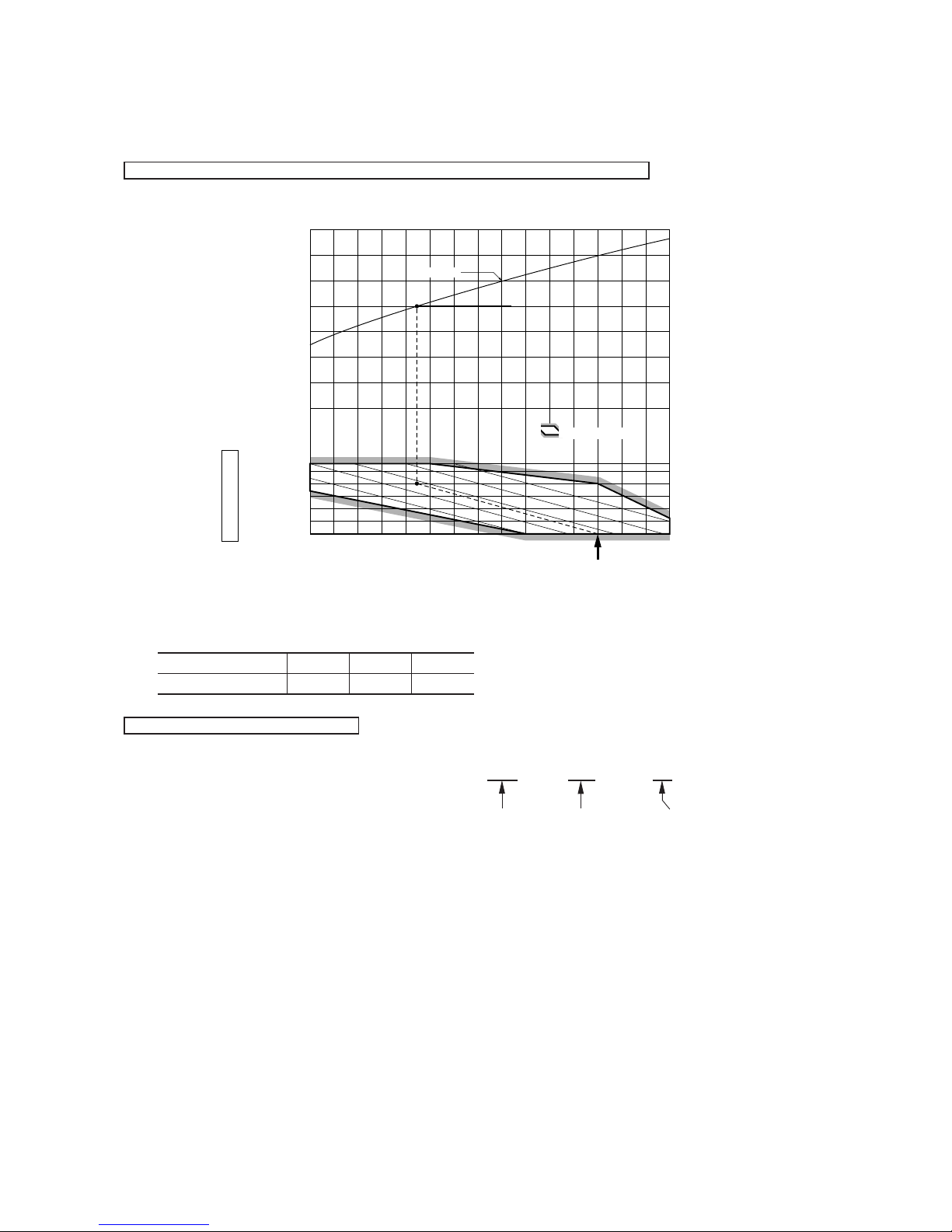
2.5 Selection chart
Correct the cooling capacity in accordance with the conditions as follows. The net cooling capacity can be obtained in the following way.
Net capacity = Capacity shown on specification ✕ Correction factors as follows.
(1) Coefficient of cooling capacity in relation to temperatures
(2) Correction of cooling capacity in relation to one way length of refrigerant piping
It is necessary to correct the cooling capacity in relation to the one way piping length between the indoor and outdoor units.
14 16 18 20 22
15
20
25
30
35
40
0.6
0.7
0.8
0.9
1.0
1.1
1.2
1.3
43
24
ISO-T1 Standard ConditionIndoor air W.B. temperature °C W.B.
Cooling
Applicable range
Coefficient of cooling
capacity in relation
to temperature
Cooling operation
Outdoor air D.B.
temperature
°C D.B.
Piping length [m]
Cooling
7
1.0
10
0.99
15
0.975
How to obtain the cooling capacity
Example : The net cooling capacity of the model SRK13CDV-4 with the piping length of 15m, indoor wet-bulb temperature at 19.0˚C
and outdoor dry-bulb temperature 35˚C is Net cooling capacity = 3810 ✕ 0.975 ✕ 1.0 = 3715 w
SRK13CDV-4
Length 15m
Factor by air
temperatures
-
10
-
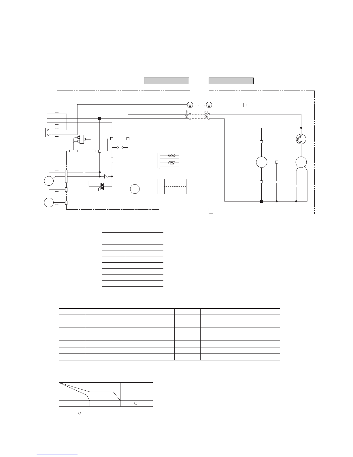
3 ELECTRICAL DATA
3.1 Electrical wiring
Models SRK10CDV-1, 10CDV-4
Power source
1 Phase 220V 50Hz
CM
52C
Printed circuit board
51C
FMo
BK
BK
T2
Th
2
T1
Th
1
BK
BKWH
WH
CNC
CNE
CNM CNW
CNU
CNC
Sh1
52C352C4
Tr
N
52C
CNB
Y/GN
LB
Y1
5
3
WH
RD
BR
WH
BK
WH
WH
WH
WH
WH
RD
WH
BK
L2
2
3
1
L3
L1ShCFO
ZNR
F
(3.15A)
CFI
Cc
OR
OR
Wireless
Display
R-Amp
HEAT
EXCHANGER
FM
I
SM
Indoor unit Outdoor unit
Notes (1) : denotes magentized relay × : denotes demagnetized relay
(2) Th
1 is room temperature thermistor. Th2 (the heat exchanger thermistor) is frost prevention thermistor.
Operation
Cooling
Relay symbol Control part
52C CM
Tab le of relay operations
Symbol Parts name Symbol Parts name
C
C
Capacitor for CM SM Flap motor
CF
I
Capacitor for FM
I
Th1,
2
Thermistor
CF
O
Capacitor for FM
O
Tr Transformer
CM Compressor motor ZNR Varistor
F Fuse 51C Motor protector for CM
FM
I
Fan motor (Indoor unit) 52C Magnetic contactor for CM
FM
O
Fan motor (Outdoor unit)
Meaning of marks
BK Black
BL Blue
BR Brown
LB Light blue
YYellow
RD Red
OR Orange
WH White
Y/G Yellow/Green
Color symbol
-
11
-
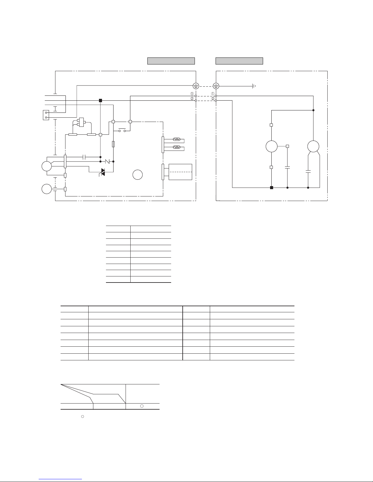
Model SRK13CDV-1, 13CDV-4
Power source
1 Phase 220V 50Hz
CM
52C
Printed circuit board
FMo
BK
BK
T2
Th
2
T1
Th
1
BK
BKWH
WH
CNC
CNE
CNM CNW
CNU
CNC
Sh1
52C352C4
Tr
N
52C
CNB
Y/GN
LB
Y1
5
3
WH
RD
BR
WH
BK
WH
WH
WH
WH
WH
RD
WH
BK
L2
L3
L1ShCFO
ZNR
F
(3.15A)
CFI
Cc
OR
OR
Wireless
Display
R-Amp
HEAT
EXCHANGER
FM
I
SM
Indoor unit Outdoor unit
Symbol Parts name Symbol Parts name
C
C
Capacitor for CM SM Flap motor
CF
I
Capacitor for FM
I
Th1,
2
Thermistor
CF
O
Capacitor for FM
O
Tr Transformer
CM Compressor motor ZNR Varistor
F Fuse 52C Magnetic contactor for CM
FM
I
Fan motor (Indoor unit)
FM
O
Fan motor (Outdoor unit)
Meaning of marks
BK Black
BL Blue
BR Brown
LB Light blue
YYellow
RD Red
OR Orange
WH White
Y/G Yellow/Green
Color symbol
Notes (1) : denotes magentized relay × : denotes demagnetized relay
(2) Th
1 is room temperature thermistor. Th2 (the heat exchanger thermistor) is frost prevention thermistor.
Operation
Cooling
Relay symbol Control part
52C CM
Table of relay operations
-
12
-
LO
MED
HI
AUTO
HI POWER
ECONO
ON OFF
AM PM
HI POWER
TEMP
ECONO
AIR FLOW
CANCEL
ON OFF
RESERVE
TIMER
TIME
ACL
FAN SPEED
ON
MODE
LO
MED
HI
AUTO
TIME
OFF
HI POWER
ECONO
ON OFF
AM PM
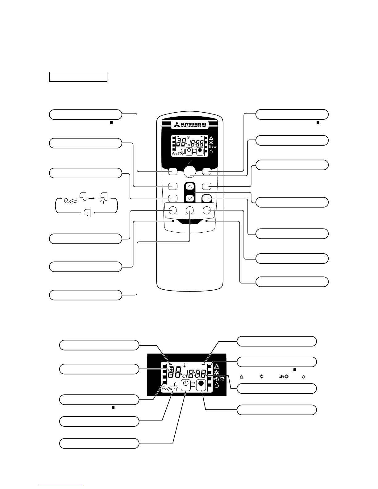
FAN SPEED button
Each time the button is pushed, the indicator is switched over in turn.
• The above illustration shows all controls, but in practice
only the relevant parts are shown.
OPERATION MODE select button
Each time the button is pushed, the indicator is switched over in turn.
AIR FLOW button
This button changes the flap mode. When
pressed, this button changes the mode in the
following order:
ON/OFF button
Press for starting operation, press again for
stopping.
HI POWER button
This button changes the HI POWER mode.
ECONOMY button
This button changes the ECONOMY mode.
RESET switch
Switch for resetting microcomputer.
ON TIMER button
This button selects ON TIMER operation.
Clock switch
This switch for setting the clock.
OFF TIMER button
This button selects OFF TIMER operation.
TEMPERATURE button
This button sets the room temperature.
(This button changes the present time and
TIMER time.)
CANCEL button
This button cancels the ON timer and OFF
timer.
RESERVE button
This button sets the present time and
TIMER time.
S Indication section
OPERATION MODE Indicator
Indicates selected operation with lamp.
[
(Auto) • (Cool) • (Fan) • (Dry)]
TEMPERATURE Indicator
Indicates set temperature.
(Does not indicate temperature when operation
mode is on AUTO)
FAN SPEED Indicator
Indicates set air flow rate with lamp.
AIR FLOW Indicator
Shows selected flap mode.
HI POWER MODE indicator
Indicates during Hi power mode operation.
ECONOMY MODE indicator
Indicates during economy mode operation.
ON TIMER Indicator
Indicates during ON TIMER operation.
Clock Indicator
Indicates present time or timer setting time.
OFF TIMER Indicator
Indicates during OFF TIMER operation.
Models All models
Remote controller
S Operation section
(Air scroll) (SWING)
4 OUTLINE OF OPERATION CONTROL BY MICROCOMPUTER
(1) Operation control function by remote controller
-
13
-
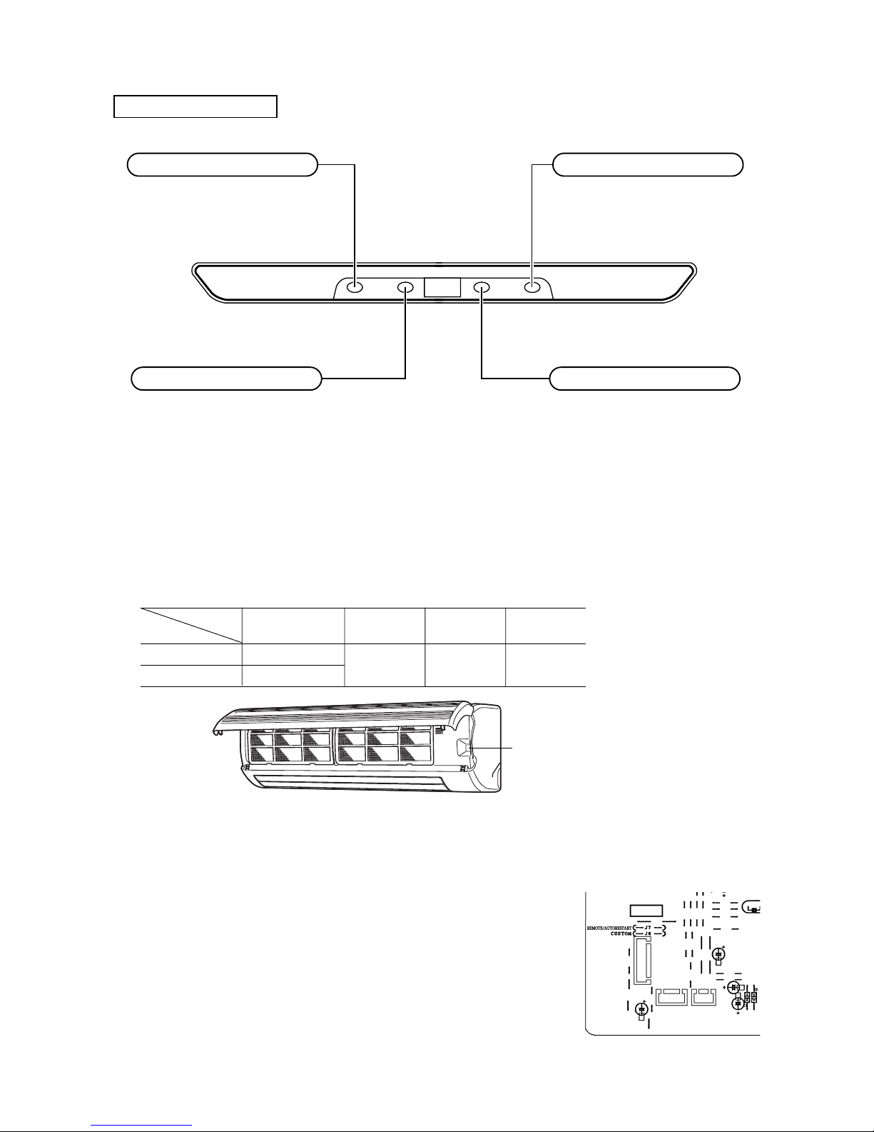
Unit indication section
Models All models
RUN HIPOWER ECONO TIMER
RUN light (green)
• Illuminates during operation.
TIMER light (yellow)
Illuminates during TIMER operation.
ECONOMY light (orange)
Illuminates during ECONOMY operation.
HI POWER light (green)
Illuminates during HI POWER operation.
(2) Back-up switch
When the remote controller batteries become weak, or if the remote controller is lost or malfunctioning, this switch may be used
to turn the unit on and off.
(a) Operation
Push the switch once to place the unit in the automatic mode. Push it once more to turn the unit off.
(b) Details of operation
The unit will go into the automatic mode in which it automatically determines, from room temperature (as detected by
sensor), whether to go into the cooling or thermal dry modes.
(3) Power blackout auto restart function
(a) Power blackout auto restart function is that records the operational status of the air-conditioner immediately prior to it being
switched off by a power cut, and then automatically resumes operations at that point after the power has been restored.
(b) The following settings will be cancelled:
1) Timer settings
2) High-power operations
Notes (1) The power blackout auto restart function is set at on when the air-conditioner is shipped from the factory.
Consult with your dealer if this function needs to be switched off.
(2) When power failure ocurrs, the timer setting is cancelled. Once power is resumed, reset the timer.
(3)
If the jumper wire (J7) “REMOTE/AUTORESTART” is cut, auto restart is disabled. (See the diagram at right)
Function
Room temperature
Operation mode
setting
Fan speed Flap Timer switch
Cooling About 25ºC
Thermal dry About 25ºC
Auto Auto Continuous
ON/OFF button
-
14
-
(5) Comfort timer setting
If the timer is set at ON when the operation select switch is set at the cooling, or the cooling in auto mode operation is selected, the
comfort timer starts and determines the starting time of next operation based on the initial value of 15 minutes and the relationship
between the room temperature at the setting time (temperature of room temperature thermistor) and the setting temperature. (Max. 60
minutes)
Operation mode Operation start time correction value (Min.)
3 < Room temp. – Setting temp. 1 < Room temp. – Setting temp.
=
<
3 Room temp. – Setting temp.
=
<
1
At cooling
+5 No change –5
Notes (1) At 5 minutes before the timer ON time, operation starts regardless of the temperature of the room temperature thermistor (Th1).
(2) This function does not actuate when the operation select switch is set at the dehumidifying as well as the dehumidifying in the auto mode.
However, the operation of item (1) above is performed during the dehumidifying in the auto mode.
(3) During the pleasant reservation operation, both the operation lamp and timer lamp illuminate and the timer lamp goes off after expiration of the timer, ON setting
time.
(4) Flap control
Control the flap by AIRFLOW button on the wireless remote controller.
(a) Air scroll
The flap will be automatically set to the angle of air flow best to operation.
1) Starting time of operation
2) When not operating
The flap returns to the position of air flow directly below, when operation has stopped.
(b) Memory flap
While the flap is operating if the AIRFLOW button is pushed once, it stops swinging at an angle.
As this angle is memorized in the microcomputer, the flap will be automatically set to the angle when next operation is
started.
¡ Recommendable stopping angle of the flap
(c) Swing flap
Flap moves in upward and downward directions continuously.
Horizontal
blowing
COOL•DRY
Corrects the starting time of next operation by
calculating the temperature difference.
(Example) Cooling
Room temperature
Setting temperature
Operation starting time
Time
Setting time
15 min. 10 min. 5 min.
earlier earlier earlier
¡ If the difference (= Room temperature – Setting tempera-
ture) is 4ºC, the correction value is found to be +5 minutes from the table shown above so that the starting time
of next operation is determined as follows:
15 min. earlier + 5 min. = 20 min. earlier
↑↑
Current operation Correction value
start time
s
During cooling and
t
dry operation
Thick line : Rapid movement
Thin line : Slow movement
Stops for approximately
5 seconds in the
horizontal position.
-
15
-
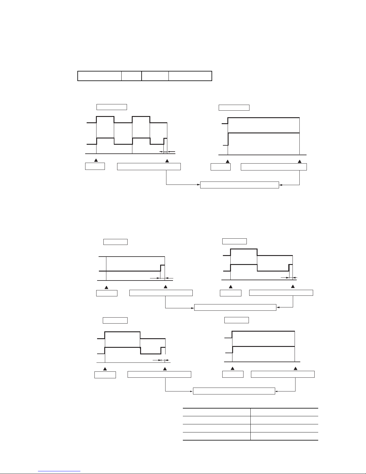
(6) Outline of cooling operation
(a) Operation of major fanctinal components
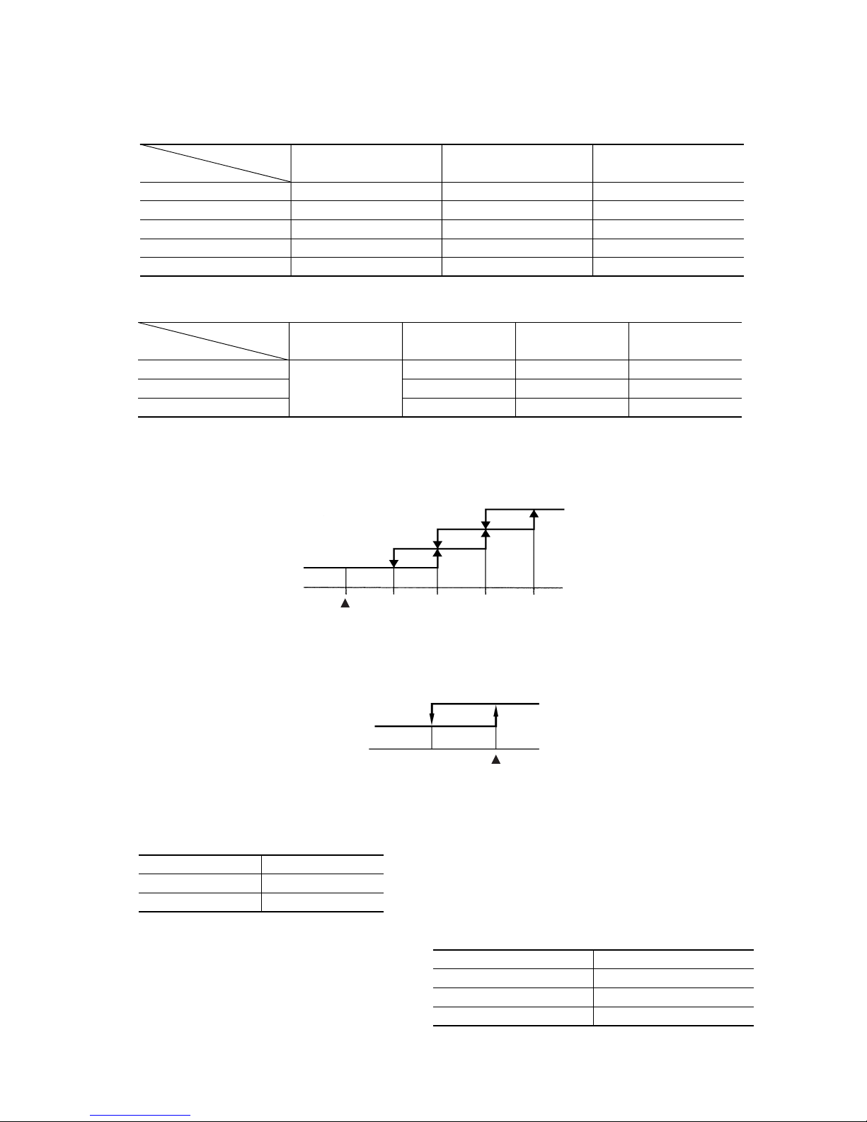
(b) Fan speed switching
1) Auto fan control
The indoor fan is automatically controlled in accordance with the difference between the room temperature (detected
by the room temperature thermistor) and the termostat setting as shown below.
(c) Thermostat operation
The compressor and outdoor fan and turned on and off as shown below according to the temperature setting.
(d) High Power operation ( “HI POWER” button on the remote controller : ON)
The following operation is performed for 15 minutes without relation to the set temperature or fan speed setting.
(e) ECONO Operation ( “ECONO” button on the remote controller : ON)
The set temperature changes as shown at right, and
the indoor unit fan speed is set on speed 2.
Notes (1) Room temperature is not adjusted during the HI POWER operation.
(2) Protective functions will actuate with priority even during the HI POWER operation.
Indoor fan motor
Flaps
Display
52C
Outdoor fan motor
ON
ON or OFF
Lights up
OFF
OFF
ON
ON or OFF
Lights up
ON
ON
OFF
Stop position control
Lights up or flashes
OFF
OFF
When the compressor
command is OFF
When the compressor
command is ON
When the compressor goes
OFF due to an abnormal stop.
Functional
components
Item
Air scroll
Swing flap
Swing stop
Auto fan control
Speed 5
Speed 5
Speed 5
Speed 3
Speed 3
Speed 3
AUTO HIGH MED
Speed 2
Speed 2
Speed 2
LOW
Flow control
Fan speed switching
Speed 4
Speed 3
Speed 2
Thermostat setting point
Speed 5
+1 +2 +3 +4
OFF
ON
Set temp.
-1
Room temp.
Compressor
outdoor fan
Indoor unit fan
Outdoor unit fan
Compressor
Speed 6 fixed
ON
ON
Running time
Running start ~ 1 hour
1~2 hours
2 hours ~
Set temperature compensation
Set temperature +0.5
Set temperature +1.0
Set temperature +1.5
-
16
-
Note (1) Thermostat operation is performed in A, B Block. When compressor and indoor fan stop by thermostat operation within 12 minutes from start, temperature
check is performed by operating indoor fan at speed 1 for 20 seconds before finishing 12 minutes and allowing decision of next operation block.
(c) DRY operation
After finishing start up operation described in (2) above, thermal dry operation is performed at 8 minutes intervals, according
to the difference between room temperature and thermostat setting temperature as shown below.
Beside, 1 cycle of this operating time consists of 8 minutes, 7 cycle operation is performed then.
(7) Outline of dehumidifying operation
(a) Choose the appropriate operation block area by the difference between room temperature and thermo-
stat setting temperature as shown below.
¡ Operation block area
(b) Start up operation
ON
OFF
OFF
0
3
6
912
ON
OFF
OFF
0
12
Compressor
and
outdoor fan
Set fan speed
Indoor fan
Start Temperature check
Start
Temperature check
Compressor
and
outdoor fan
Set fan speed
Indoor fan
Operation block decision
C.D Block
A.B Block
minutes
minutes
Speed 1Speed 1
20
seconds
ON
OFF
OFF
0
4
8
ON
OFF
OFF
0
8
Compressor
and
outdoor fan
Indoor fan
D Block
Compressor
and
outdoor fan
Indoor fan
C Block
Compressor
and
outdoor fan
Indoor fan
B Block
Compressor
and
outdoor fan
Indoor fan
A Block
20 seconds
20 seconds
minutes
minutes
Start Temperature check Start Temperature check
Operation block decision
20 seconds
minutes
minutes
Start Temperature check Temperature check
Operation block decision
Start
Speed 1
Speed 1
OFF
OFF
0
8
ON
OFF
OFF
0
3
8
Speed 1
Speed 1
Running time
Running start ~ 1 hour
1~2 hours
2 hours ~
Set temperature compensation
Set temperature +0.5
Set temperature +1.0
Set temperature +1.5
(d) ECONO Operation ( “ECONO” button on the remote controlle : ON)
The set temperature changes as shown at right, and
the indoor unit fan speed is set on speed 2.
D Block C Block B Block A Block
–2 0 +3
Room temp. – Setting temp.(deg)
-
17
-
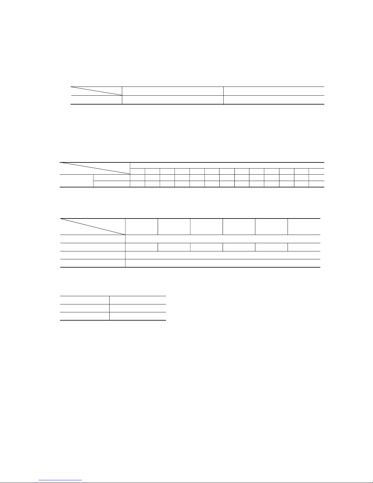
(8) Automatic operation
(a) Determination of operation mode
The blow operation of the indoor fan is carried out at the 1st speed for 20 seconds and the room temperature is checked to
determine the operation mode automatically. (When the unit is operated by the turn-on timer, the blow operation is not
carried out.)
(9) Outline of fan operation
(a) Operation of major fanctional components
(b) High Power operation (“HI POWER” button on the remote controller : ON)
The following operation is performed for 15 minutes without relation to the set fan speed.
52C
Indoor fan motor
Outdoor fan motor
Flaps
Speed 6 Speed 5 Speed 5
OFF
OFF
ON or OFF
Speed 3 Speed 2 Speed 1
High power AUTO HIGH MED LOW ECONO
Functional
components
Fan speed switching
Indoor unit fan
Outdoor unit fan
Compressor
Speed 6 fixed
OFF
OFF
Note (1) Protective functions will actuate with priority even during the HI POWER operation.
Room temperature<26ºC 26ºC
<
=
Room temperature
Operation mode Dry Cooling
(b) Within 30 minutes after either auto or manual operation stops, if auto operation is started, or if you switch to auto operation
during manual operation, the system runs in the previous operation mode.
(c) The temperature is checked 1 time in 30 minutes after the start of operation, and if the judgment differs from the previous
operation mode, the operation mode changes.
(d) Setting temperature can be adjusted within the following range. There is the relationship as shown below between the signals
of the wireless remote controller and the setting temperature.
Signals of wireless remote controller (Display)
–6 –5 –4 –3 –2 –1 ±0+1+2+3+4+5+6
Setting Cooling 19 20 21 22 23 24 25 26 27 28 29 30 31
temperature Dehumidifying 19 20 21 22 23 24 25 26 27 28 29 30 31
-
18
-
(10) Protective control function
(a) Dew condensation prevention control for cooling operation
This prevents dew condensation, in the indoor unit, from occurring.
1) Operating condition: when 52C is kept ON for 30 min. after the unit starts operation.
2) Operation content: forces the indoor fan to change from Speed 1 to Speed 2.
3) Resetting condition: When 52C is off, or when dew condensation prevention control has been operating continu-
ously for 30 minutes.
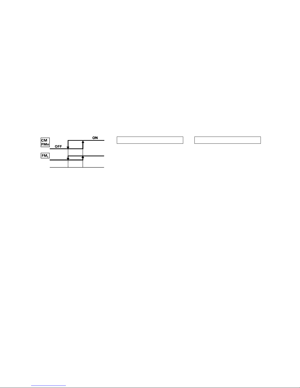
(b) Frost prevention for indoor heat exchanger [Preventing frost accumulation on the indoor heat exchanger]
During the Cooling or Dry operation in low room air temp. condition, evaporating temperature will decrease and conse-
quently indoor heat exchanger sometimes gets clogged with frost (or ice).
In order to prevent this trouble, compressor is stopped by under mentioned condition by indoor heat exchanger sensor (Th
2)
and timer (built into micro computer circuit) functions.
Also indoor fan is changed over to speed 1.
CM, FMO stoppage condition
1 Temperature of heat exchanger is
2.5˚C or lower.
2 As least 3 minutes has passed since
the compressor started.
Indoor heat exchanger
temperature (˚C)
CM, FMO re-starting condition
1 Te mperature of heat exchanger is
8˚C or higher.
2 As least 3 minutes has passed since
the compressor stopped.
Set fan
speed
speed 1
(d) Self diagnosis function
When something abnormal happens on the outdoor unit, indoor unit fan motor and each thermistor (heat exchanger, room
temperature, ) it will be indicated by flashing lamps.
1) Abnormality of outdoor unit: When the indoor heat exchanger temperature does not fall to 25ºC or below for 40
minutes after 5 minutes have elapsed since the compressor operation start, the
abnormality stop occurs. (The timer lamp flashes 2 times.)
2) Abnormality of indoor fan motor: The indoor fan motor revolves at a rate under 300 rpm for 30 seconds or
longer, the RUN lamp will flash.
3) Abnormality of heat exchanger thermistor: RUN lamp will flashing when the input temperature of the heat
exchanger thermistor measures less than –20ºC for more than 15
seconds with the airconditioner “OFF”. (will not flashing during
operation)
4) Abnormality room temperature thermistor: RUN lamp will flashing when the input temperature of the room
temperature thermistor measures less than –20ºC for more than
15 seconds with the airconditioner “OFF”. (will not flashing during
operation)
Note (1) If the above abnormalities happen concurrently, the lamp will flashing in the order of item number 1) through 4) above.
(c) Three-Minute Forced Operation
When the compressor begins operating the thermal operation is not effective for 3 minutes, so operation continues as is in the
operation mode. (After 3 minutes has passed the thermal operation is effective.)
However, stopping the compressor via a stop signal or protection control has priority.
2.5 8

-
19
-
5 APPLICATION DATA
SAFETY PRECAUTIONS
¡ Please read these “Safety Precautions” first then accurately execute the installation work.
¡
Though the precautionary points indicated herein are divided under two headings, WARNING and CAUTION , those points
which are related to the strong possibility of an installation done in error resulting in death or serious injury are listed in the
WARNING section. However, there is also a possibility of serious consequences in relationship to the points listed in the
CAUTION section as well. In either case, important safety related information is indicated, so by all means, properly observe all
that is mentioned.
¡ After completing the installation, along with confirming that no abnormalities were seen from the operation tests, please explain
operating methods as well as maintenance methods to the user (customer) of this equipment, based on the owner’s manual.
Moreover, ask the customer to keep this sheet together with the owner’s manual.
WARNING
¡ To disconnect the appliance from the mains supply this appliance must be connected to the mains by means of
a circuit breaker or a switch (use a recognized 16A) with a contact separation of at least 3mm.
¡ The appliance shall be installed in accordance with national wiring regulations.
¡ This system should be applied to places as households, residences and the like. Application to inferior environ-
ment such as engineering shop could cause equipment malfunction.
¡ Please entrust installation to either the company which sold you the equipment or to a professional contractor.
Defects from improper installations can be the cause of water leakage, electric shocks and fires.
¡ Execute the installation accurately, based on following the installation manual. Again, improper installations can
result in water leakage, electric shocks and fires.
¡ For installation, confirm that the installation site can sufficiently support heavy weight. When strength is insuffi-
cient, injury can result from a falling of the unit.
¡ For electrical work, please see that a licensed electrician executes the work while following the safety standards
related to electrical equipment, and local regulations as well as the installation instructions, and that only exclusive use circuits are used.
Insufficient power source circuit capacity and defective installment execution can be the cause of electric shocks
and fires.
¡ Accurately connect wiring using the proper cable, and insure that the external force of the cable is not conducted
to the terminal connection part, through properly securing it improper connection or securing can result in heat
generation or fire.
¡ Ta ke care that wiring does not rise upward ,and accurately install the lid/service panel.It’s improper installation
can also result heat generation or fire.
¡ When setting up or moving the location of the air conditioner, do not mix air etc. or anything other than the
designated refrigerant (R22) within the refrigeration cycle.
Rupture and injury caused by abnormal high pressure can result from such mixing.
¡ Always use accessory parts and authorized parts for installation construction. Using parts not authorized by this
company can result in water leakage, electric shock, fire and refrigerant leakage.
¡ Ventilate the work area when refrigerant leaks during the operation.
Coming in contact with fire, refrigerant could generate toxic gas.
¡ Confirm after the foundation construction work that refrigerant does not leak.
If coming in contact with fire of a fan heater, a stove or movable cooking stove, etc., refrigerant leaking in the
room could generate toxic gas.
CAUTION
¡ Execute proper grounding. Do not connect the ground wire to a gas pipe, water pipe, lightning rod or a telephone
ground wire.
Improper placement of ground wires can result in electric shock.
¡ The installation of an earth leakage breaker is necessary depending on the established location of the unit.
No installing an earth leakage breaker may result in electric shock.
¡ Do not install the unit where there is a concern about leakage of combustible gas.
The rare even of leaked gas collecting around the unit could result in an outbreak of fire.
¡ For the drain pipe, follow the installation manual to insure that it allows proper drainage and thermally insulate it
to prevent condensation. Inadequate plumbing can result in water leakage and water damage to interior items.
-
20
-
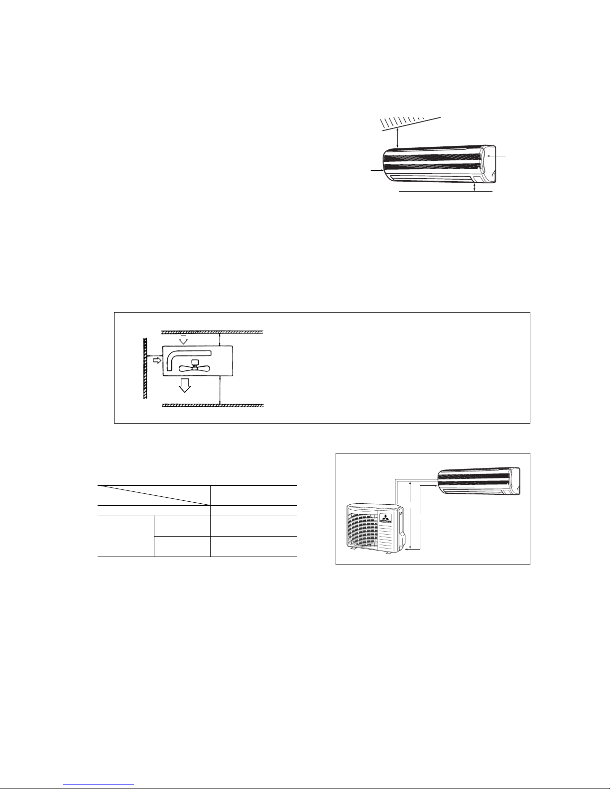
5.1 Selection of location for installation
(1) Indoor unit
(a) Where there is no obstructions to the air flow and where the cooled
air can be evenly distributed.
(b) A solid place where the unit or the wall will not vibrate.
(c) A place where there will be enough space for servicing. (Where
space mentioned below can be secured)
(d) Where wiring and the piping work will be easy to conduct.
(e) The place where receiving part is not exposed to the direct rays of
the sun or the strong rays of the street lighting.
(2) Outdoor unit
(a) A place where good air circulation can be obtained and where rain, snow or sunshine will not directly strike the unit.
(b) A place where discharged hot air or unit’s operating sound will not be a nuisance to the neighborhood.
(c) A place where servicing space can be secured.
(d) A place where vibration will not be enlarged.
Model
All models
Item
One way piping length (R) 15 m
Outdoor
unit is lower
5 m
Outdoor unit
is higher
5 m
r
h
Left
side
Right
side
5 cm
10 cm
1.5 cm
6.5 cm
Air inlet
Air inlet
Air
Outlet
100
100
600
No obstacles
(Service space
for electrical
parts)
Unit : mm
Notes (1) Blowing out port and suction port on the back side of the unit can be
installed at a distance of 10cm from walls.
In case the barrier is 1.2m or above in height, or is overhead, the
sufficient space between the unit and wall shall be secured.
(2) When the unit is installed, the space of the following dimension and
above shall be secured.
(3) Limitations for one way piping length and vertical
height difference.
()
Vertical height
difference (H)
-
21
-
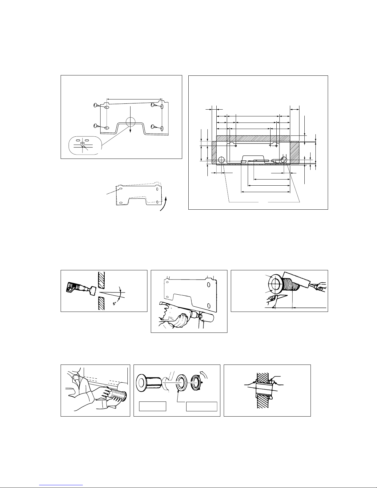
Adjustment of the installation board in the horizontal
direction is to be conducted with four screws in a
temporary tightened state.
5.2 Installation of indoor unit
(1) Installation of installation board
(a) Fixing of installation board
(2) Drilling of holes and fixture sleeve (Option Parts)
When drilling the wall that contains a metal lath, wire lath or metal plate, be sure to use pipe hole sleeve sold separately.
(a) Drill a hole with ø65
whole core drill
(b) Adjusting sleeve length
Adjust so that board will be level by turning the board
with the standard hole as the center.
Standard hole
(c) Install the sleeve
(Inserting sleeve) (*Sleeve + *Inclined + *Sealing plate)
Note (1) Drill a hall with incline of 5 degree from
indoor side to outdoor side.
Indoor side Outdoor side
Cut off the sleeve
collar in case of
drawing piping out
to rear.
Cut off the sleeve
collar that can be
seen from beneath
the unit.
Wall thickness
+ 1.5 cm
Indoor side Outdoor side
Turn to
tighten
Paste
View of sleeve when installed
Inclined
flange
Sealing
plate
Sleeve
Indoor side Outdoor side
Look for the inside wall structures (Intersediate support or
pillar and firaly install the unit after level surface has been
checked.)
Mating mark for level surface
450
580
450
450
117.5
148.5
216.5
117.5
42.7175
65 Speace
for service
15Speace
for service
8.2236.1
44.5
5.7
47.244.5
Speace for
service
50
Speace for
service
100
216.5
148.5
67.553.5
Piping hole (ø65)Piping hole (ø65)
Piping for Gas 397.1
Piping for Liquid 465.1
Drain hose 540(ø16)
INSTALLATION SPACE (INDOOR UNIT) (FRONT VIEW)
Unit : mm
-
22
-
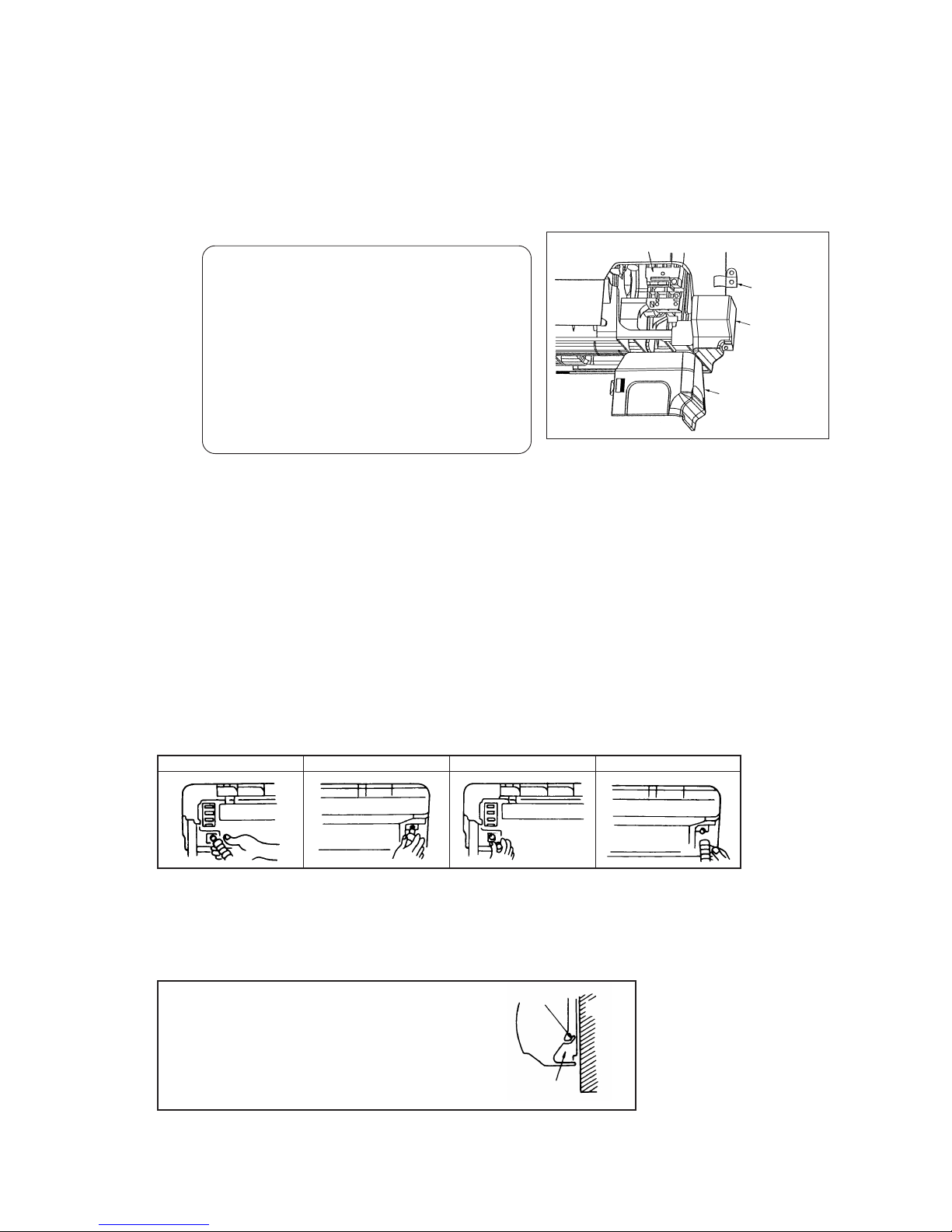
(3) Preparation of indoor unit
(a) Mounting of connecting wires
1) Remove the lid (R).
2) Remove the terminal cover.
3) Remove the wiring clamp.
4) Connect the connecting wire securely to the terminal block.
(b) Protective taping (Protect the cable with tape at the section where the cable passes through the hole opened on the wall.)
(c) Forming of pipe (Holding down the pipe at the root, change the pipe direction, extend it and adjust according to the
circumstance.)
[When the pipe is extended to left and taken out from the rear center]
(Drain pipe relocation procedure)
1.
Remove the drain pipe.
2. Remove the drain cap. 3. Insert the drain cap. 4.
Connect the drain pipe.
¡ Loosen the spring
clamp and securely
insert the drain pipe.
Note: If it is inserted in-
sufficiently, water
leakage could result.
¡ Loosen the spring
clamp to remove.
¡ Remove by hand or
use cutting pliers, etc.
¡ Securely insert the
drain cap removed in
the step 2.
Note: If it is inserted in
sufficiently, water
leakage could result.
Since this air conditioner has been designed to collect dew
drops on the rear surface to the drain pan, do not attach the
power cord above the gutter.
Gutter
Wall
Pipe accommodation section
1 Connect the connection wire securely to the terminal block. If the wire is not affixed completely, contact will be
poor,and it is dangerous as the terminal block may heat up and catch fire.
2 Take care not to confuse the terminal numbers for indoor and outdoor connections.
3 Affix the connection wire using the wiring clamp.
5) Fix the connecting wire by wiring clamp.
6) Attach the lid.
7) Close the suction grille.
Use cables for interconnection wiring to avoid loosening of the
wires.
CENELEC code for cables. Required field cables.
H05 RNR3G1.5 (Example) or 245IEC57
H Harmonized cable type
05 300/500 volts
R Natural-and/or synth, rubber wire insulation
N Polychloroprene rubber conductors insulation
R Standed core
4or5 Number of conductors
G One conductor of the cable is the earth conductor (yellow/
green)
1.5 Section of copper wire (mm2)
Clamp
Terminal cover
Lid (R)
Terminal block
-
23
-
(4) Installation on indoor unit
(a) Install the indoor unit on the mounting plate.
Hook the upper part of the indoor unit on the stoppers disposed at the upper part of the mounting plate and lightly push the
lower part of the indoor unit so that the unit is fixed in position.
¡ When removing the indoor unit
1) Disconnect the lid at right and left.
2) Pull down the stoppers (right and left) provided at the bottom of the indoor unit base.
(See the detail view shown at right.)
(b) Be sure not to leave any trap on the drain pipe.
5.3 Installation of outdoor unit
(1) Installation of outdoor unit
(a) Make sure that sufficient space for installation and service is secured.
(b) Fix the leg sections of the unit on a firm base which will not play.
Attach cushion pads, etc. between the unit and the mounting fixtures not to transmit vibration to the building.
(c) Attach a drain elbow, etc. under the drain port of the bottom plate to guide drain water.
(Drain elbow should not be used where days when temperature drops below 0°C continue for several days. Draining may be
disturbed by frozen water.)
(d) When installing the unit at a higher place or where it could be toppled with strong winds, secure the unit firmly with foundation
bolts, wire, etc.
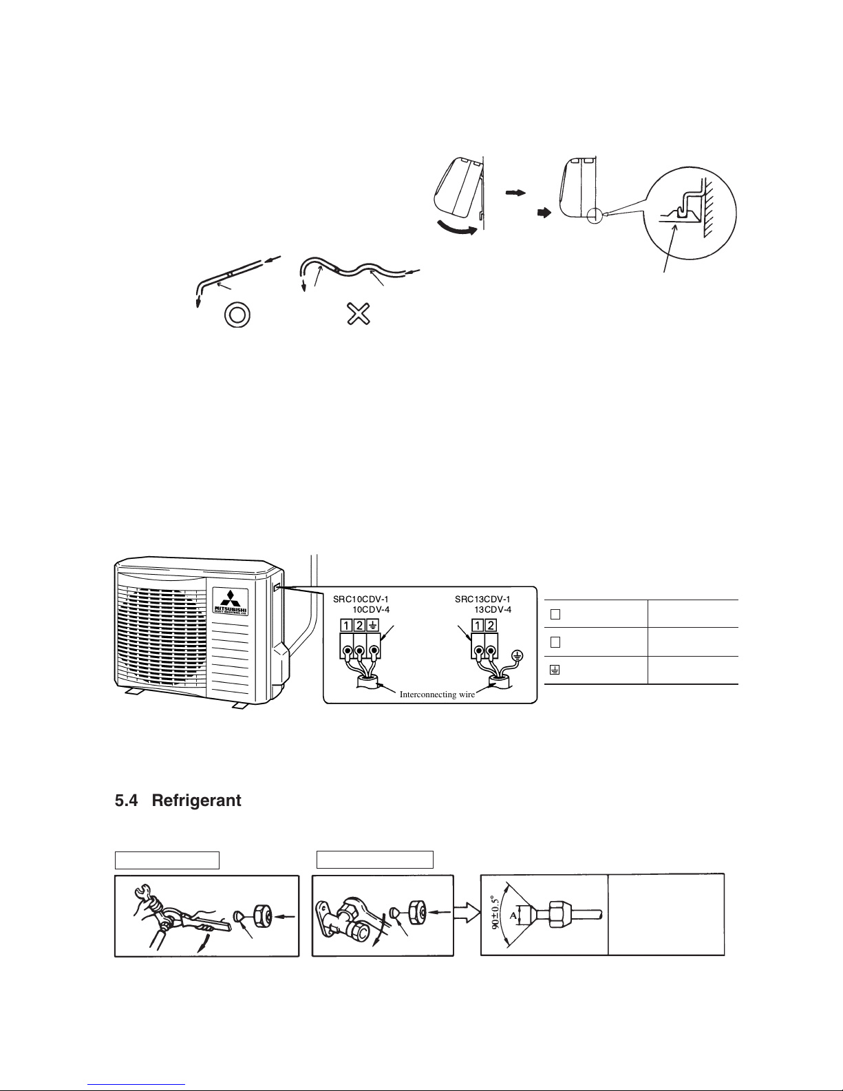
(2) Connection of indoor and outdoor connecting wiring
(a) Connect the wiring according to the number of the indoor terminal block. (Mis-wiring may cause the burning damage, and
make sure to connect correctly.)
Notes (1) To prevent the mis-operation by noise, when the connecting wire too long for indoor and outdoor. Please hide the fixed wire in the pipe or
use vinyl tape to set. Do not put wire into the unit.
(2) Please let the anchorized personal to decide by indoor wiring code whether connect the leakage breaker or not.
Indoor unit base bottom stopper
(2 places at right, left)
Light push
Mounting
plate
Wall
Declining slope
Inverted slope
Trap
Terminal block
Interconnecting wire
5.4 Refrigerant piping
(1) Preparation
Keep the openings of the pipes covered with tapes etc. to prevent dust, sand, etc. from entering them.
Indoor unit side
Outdoor unit side
¡ Remove the flared nuts.
(on both liquid and gas sides)
¡ Remove the flared nuts.
(on both liquid and gas sides)
¡ Install the removed flared nuts to the pipes to be connected,
then flare the pipes.
Dimension A
Liquid side
(φ6.35): 9-9.5 dia
Gas side
(φ9.52): 13.2-14 dia
(φ12.7): 16.2-17 dia
Press
Remove
Remove
(Do not
turn)
1
Brown
For power supply,
indoor outdoor
2 Blue
For power supply,
indoor outdoor
Yellow/Green
Earth wiring
terminal
-
24
-
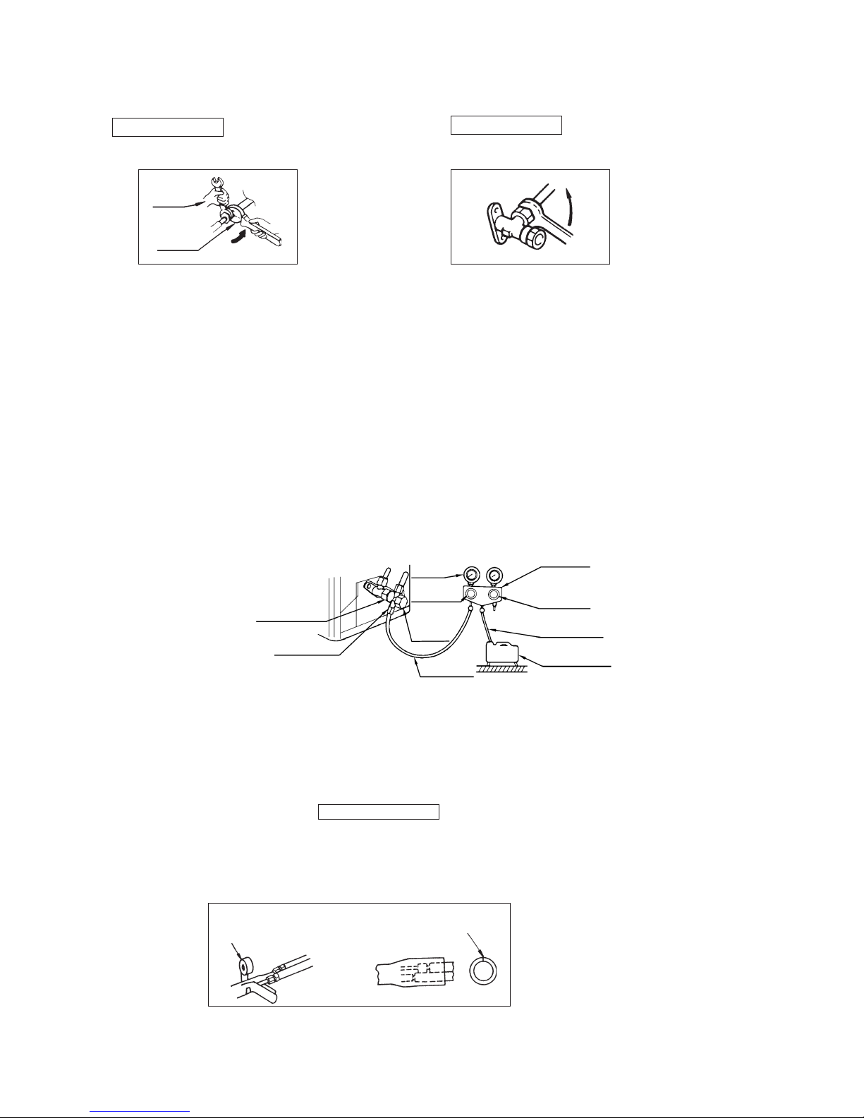
¡ Always use a Torque wrench and back up spanner to tighten the flare nut.
(3) Air purge
(a) Tighten all flare nuts in the pipings both indoor and outside will so as not to cause leak.
(b) Connect service valve, charge hose, manifold valve and vacuum pump as is illustrated below.
(c) Open manifold valve handle Lo to its full width, and perform vacuum or evacuation.
Continue the vacuum or evacuation operation for 15 minutes or more and check to see that the vacuum gauge reads – 0.1 MPa
(– 76 cmHg).
(d) After completing vacuum operation, fully open service valve (Both gas and liquid sides) with hexagon headed wrench.
(e) Check for possible leakage of gas in the connection parts of both indoor and outdoor.
(2) Connection of refrigerant piping
Indoor unit side
¡ Connect firmly gas and liquid side
pipings by Torque wrench.
Outdoor unit side
¡ Connect firmly gas and liquid side
pipings by Torque wrench.
¡ Specified torquing value:
Liquid side (ø6.35) : 15.7~19.6N·m (1.6~2.0kgf·m)
Gas side (ø9.52) : 29.4~39.2N·m (3.0~4.0kgf·m)
(ø12.7) : 39.2~49.0N·m (4.0~5.0kgf·m)
¡ Use one more spanner to fix the valve.
Spanner
(for fixing
the piping)
Torque
wrench
¡ Specified torquing value:
Liquid side (ø6.35) : 15.7~19.6N·m (1.6~2.0kgf·m)
Gas side (ø9.52) : 29.4~39.2N·m (3.0~4.0kgf·m)
(ø12.7) : 39.2~49.0N·m (4.0~5.0kgf·m)
Manifold
Valve
-76 cm Hg
Handle Lo
(pressure)
Charge hose
Stop valve
(Two-way valve)
Service port
Stop valve
(Three-way
valve)
Compound
(Gauge)
Pressure
gauge
Handle Hi
(pressure)
Charge hose
Vacuum pump
♦ Additional refrigerant charge
When refrigerant piping exceeds 7.5m conduct additional refrigerant charge after refrigerant sweeping.
7.5m over 10m:Additional charge amount per meter = 10g/m
10m over 15m:Additional charge amount per meter=30g/m
[Example]
How much amount of additional charge for 15m piping?
(10 – 7.5)m × 10g/m+(15-10)m×30g/m=175g 175g for additional charge
¡ All models
(4) Insulation of connecting portion
(a) Cover the connecting portion of the refrigerant piping with the pipe cover and seal them.
If neglecting to do so, moisture occurs on the piping and water will drip out.
Vinyl tape
To cover the connecting portion with
insulation material materials, cut upper portion
and then seal it with insulation materials.
-
25
-
(b) Finishing and fixing
(i) Tie up the piping with wrapping tape, and shape it so
that it conforms to which the pipe is attached.
(ii) Fix them with clamps as right figure.
Cover the exterior portion with covering tape and shape the piping so
it will match the contours of the
route that the piping to take. Also
fix the wiring and pipings to the
wall with clamps.
Insulation
Refrigerant piping
Electrical wiring
Covering tape
Drain hose
Tapping screw
5.5 Test run
(1) Conduct trial run after confirming that there is no gas leaks.
(2) When conducting trial run set the remote controller thermostat to continuous operation position. However when the power source
is cut off or when the unit’s operation switch is turned off or was turned to fan operation position, the unit will not go into operation
in order to protect the compressor.
(3) Insert in electric plug into the electric outlet and make sure that it is not loose.
(a) When there is something wrong with the electric outlet and if the insertion of the electric plug is insufficient, there may occur
a burn out.
(b) It is very important to be careful of above when plugging in the unit to an already furnished electrical outlet.
(4) Explain to the customer on the correct usage of the air conditioner in simple layman’s terms.
(5) Make sure that drain flows properly.
(6) Standard operation data
Note (1) The data are measured at following conditions
Ambient air temperature
Indoor side: Cooling ... 27˚C DB, 19˚C WB
Outdoor side: Cooling ... 35˚C DB, 24˚C WB
Temp. difference between
return air and supply air (°C)
(220V)
Item
Model
SRK10CDV-1, 10CDV-4 SRK13CDV-4
Low pressure MPa (kgf/cm2)0.45~0.55 (0.52MPa) 0.45~0.55 (0.51MPa)
11~15 12~16
Running current (A) 4.2 6.1
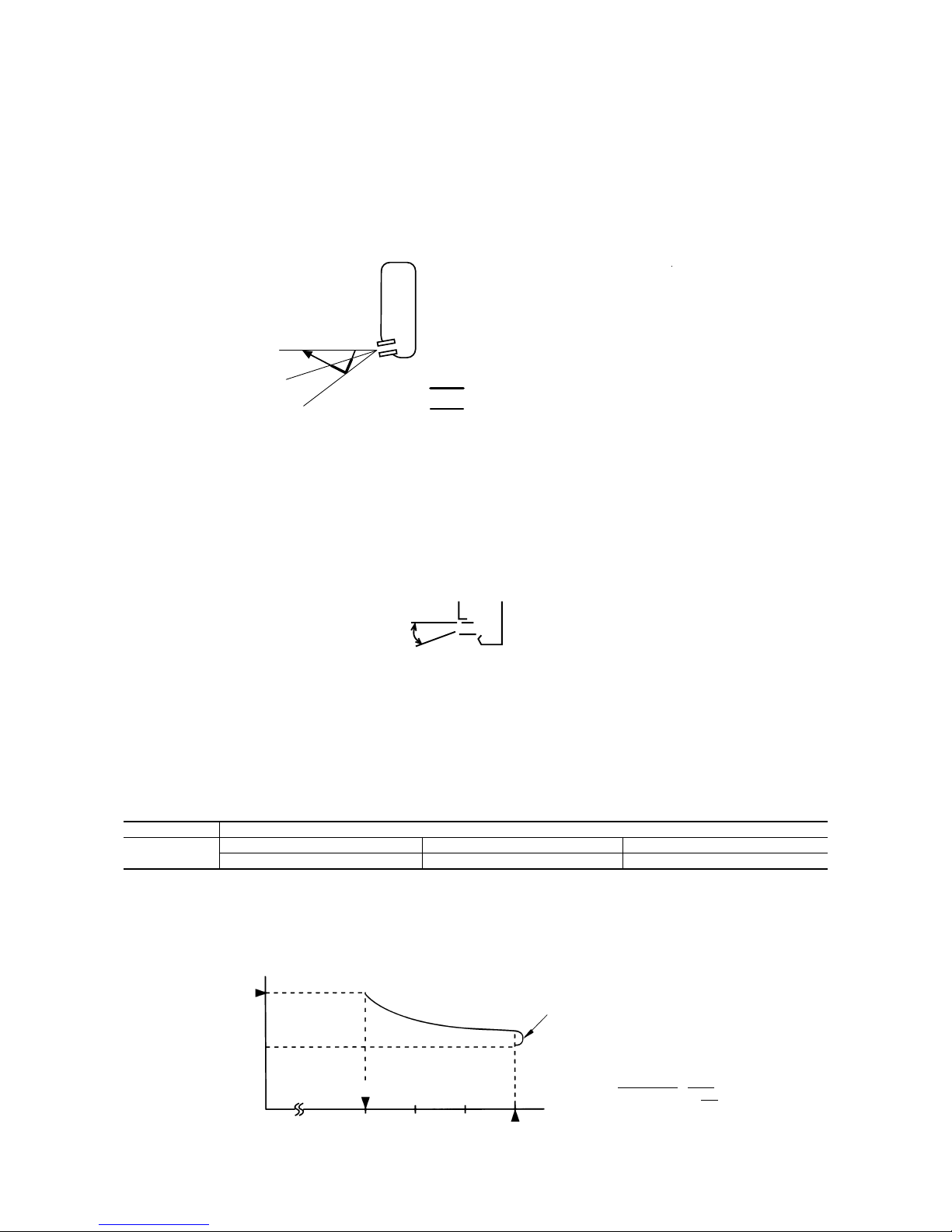
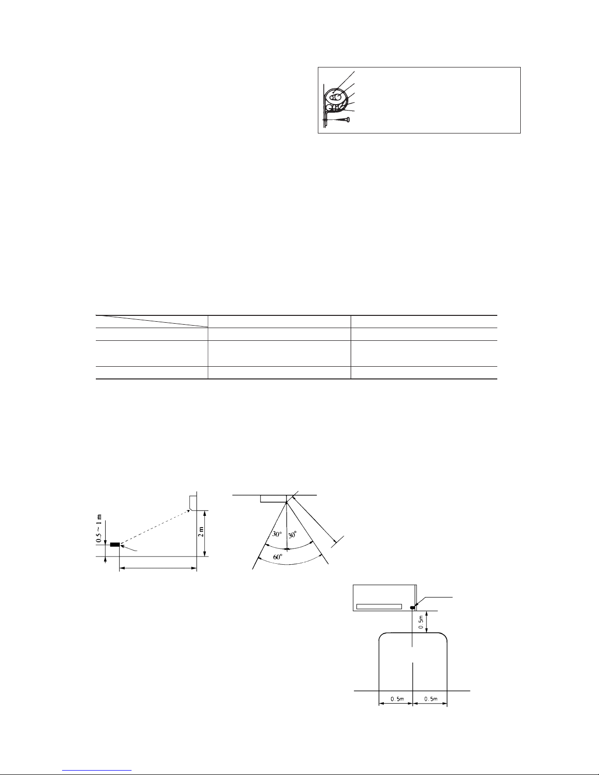
(b) When manipulating the remote controller mounted on
a wall:
Make sure that it works normally (i.e., transmission/reception
signal is audible) before mounting.
Notes (1) The remote controller is correctly facing the
sensing element of the air conditioner when being
manipulated.
(2) The typical coverage is indicated (in the left
illustration). It may be more or less depending on
the installation.
(3) The coverage may be less or even nil. If the sensing
element is exposed to strong light, such as direct
sunlight, illumination, etc., or dust is deposited on
it or it is used behind a curtain, etc.
or less
6 m or less
Wireless remote
controller
5 m or less
Remote controller
available in this area.
Receiver
or less
5.6 Precautions for wireless remote controller installation and operation
(1) Wireless remote controller covers the following distances:
(a) When operating facing the air conditioner:
or less
-
26
-
6 MAINTENANCE DATA
6.1 Trouble shooting
(1) Trouble shooting to be performed prior to exchanging PCB, (Printed circuit board) [Common to all models]
All the models described in this chapter are controlled by a microcomputer. When providing maintenance service to customers it
is necessary to understand the function controlled by a micro computer thoroughly, so as not to mistakenly identify correct opera-
tions as mis-operations. It is also necessary to perform the following simple checks before conducting detailed checks or exchang-
ing printed circuit board.
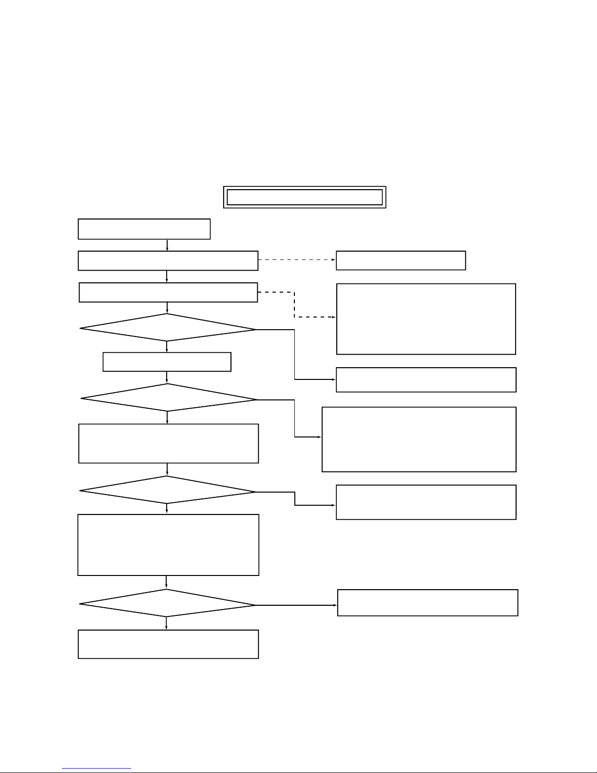
Before exchanging Printed circuit board
Claim call from the user
Ascertain the nature of the claim.
Ascertain the operation status.
Does the trouble occur again?
Is this nonsense claim?
Operate the unit.
Does the trouble occur again?
Temporarily turn off the power source and
turn it on again in about 1 min. and turn the
unit on again.
YES
No
YES
YES
Does the trouble occur again?
Disconnect connectors and connect them
again.
Operate the unit again after confirming that the fuse
and the varistor equipped on PCB does not burn out.
Carry out checks according to detailed
check process (See later page)
Unit did not cool, etc.
¡ Is the power on?
¡ Is the thermostat setting correct?
(Not too high?)
¡ Is the unit in a timer operation?
¡ Does user understand function?
etc.
¡ Explain the function of the unit to user.
No need for PCB change
Check further the status when the trouble occured
(such as the timer of occurence, power failures, thunder, use status of other electrical appliances, etc).
Clarify the reason for the problem and explain it thoroughly to the user.
No need for PCB change
Microcomputer runaway due to power source
conditions is a possible cause.
No need for PCB change
The cause is defective connector contact.
YES
No
No
No
-
27
-
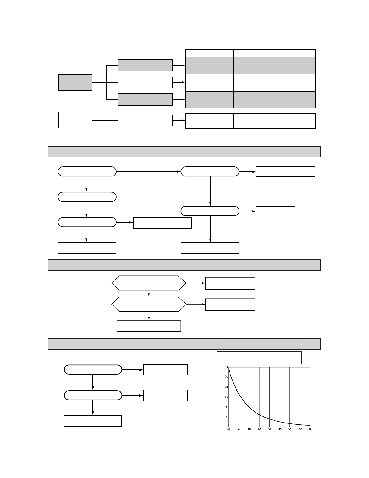
(2) Indication of Self Diagnosis (Indoor unit)
TIMER lamp
is lights
continuously.
RUN lamp is flashing.
(1 Time flash.)
RUN lamp is flashing.
(2 Time flash.)
RUN lamp is flashing.
(6 Time flash.)
TIMER lamp is flashing.
(2 Time flash.)
Connect of Defect
Abnormality of heat
exchanger thermistor.
Abnormality of room
temperature thermistor.
Abnormality of indoor
fan motor.
Abnormality of outdoor
unit.
Place of defect
¡ Disconnection of heat exchanger thermistor.
¡ Disconnection of room temperature
thermistor.
¡ Fan motor is defective.
¡ Printed circuit board is defective.
¡ Compressor is defective.
¡ Capacitor is defective.
¡ Gas is short.
RUN lamp is
lights
continuously.
Abnormality of thermistor Disconnection of thermistor and defective connection of connector
(Disconnection)
(Short circuit)
Resistance value
(kΩ)
Temperature (°C)
Is connection to connector
good?
Is thermistor resistance
value normal?
Replace PCB.
Repair connector.
Replace thermistor.
No
No
Ye s
Ye s
Chart for thermistor temperature
resistance characteristics
(3) Troubleshooting
Abnormality of outdoor unit [Compressor malfunction of insufficient gas (refrigerant)]
Abnormality of indoor fan motor (Fan motor defective, printed circuit board defective)
No
No
Ye s
Ye s
Ye s
Ye s
Ye s
No
No
Replace protective device.
Replace capacitor.
Is capacitor normal?
Insufficient gas.
Replace compressor.
Is protective device normal?
Does compressor operate?
Clogging of capillary tube. etc.
Is abnormality the same after
gas charging?
Is refrigerant circulation
volume normal?
No
No
Ye s
Ye s
The fan motor is defective.
Repair the connector.
Is voltage being applied to the
fan motor?
The indoor circuit board
is defective.
Is the connector connection
good?

-
28
-
(4) Trouble Diagnostic Procedures
Unit malfunctions or
does not stop.
Replace PCB.
Microcomputer rarely
mis-starts even during
times or power supply
or power failure, but, it
can sometimes occur
during those times. If it
occurs, check the operation, when the result is
positive then proceed as
normal.
Runaway of micro-
computer
Remove receptacle.
Insert it after 3 min.
and operate.
No change.
Normal operation.
Indoor lamp of
indoor unit does not
illuminate.
Check receptacle voltage.
Check if PCB fuse is blown.
Check varistor.
Check transformer secondary
voltage
Replace PCB.
Replace fuse.
Replace varistor.
Replace transformer
No
No
Outdoor fan does not
operate.
Check voltage with fan
connector.
Replace PCB.
Check capacitor.
Replace fan motor.
Replace capacitor.
Abnormal
Ye s
Normal
Unit Thermistor Operation
Function
Short circuit Broken connection
Cooling
Cooling
Indoor unit
Room temperature
thermistor
(1)
(Th1) except
for “continuous” thermal
setting.
Cooling will not operate
¡ FM
I : continuous operation
¡ CM,FM
o: stopped
Cooling will operate
¡ Heat exchanger frost preventer begins to operate
¡ Cools alternately for 10 minutes, stopping for 3
minutes.
(5) Trouble shooting chart for the room temperature thermistor (Th1), heat exchanger thermistor (Th2)
Continuous Cooling operation
¡ Cannot be turned ON/OFF by thermostat
¡ When FMI is on. “AUTO” is continuously
Hi
Heat exchanger
thermistor (Th
2)
Cooling will not operate.
Note (1) When the room temperature thermistor (Th
1) will not operate normally. Cooling operation may be run continuously by putting the thermostat setting on
“CONTINUOUS”
-
29
-
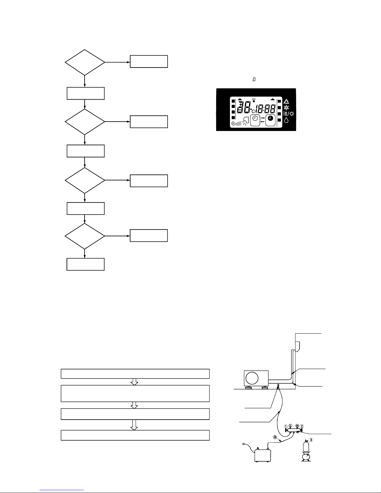
6.2 Servicing
(1) Evacuation
The evacuation is an procedure to purge impurities ...... noncondensable gas, air, moisture from the refrigerant equipment by using
a vacuum pump. Since the refrigerant R22 is very insoluble in water, even a small amount of moisture left in the refrigerant
equipment will freeze, causing what is called water clogging.
¡ Evacuation procedure
(a) Check to ensure that there is no internal pressure in the unit. If there is an internal pressure, it
should be relieved through the check joint.
(b) Connect the service hoses of the gauge manifold to the check joint of the gas & liquid piping.
(c) Connect a vacuum pump to the charge hose A . Repeat evacuation in the following sequence.
(6) How to make sure of remote controller
(1)
Is remote
controller
normal?
YES
Again pushing
operating switch
Operating the
unit?
NO
Does operating
backup switch
YES
Replace the
display
Remote controller
defects
Abnormal is not
fount
It is normal
Remote
controller defects
NO
NO
YES
NO
Note (1) How to check the remote controller
(a) Press the reset switch of remote controller.
(b) If the almost normal if entire display of remote control-
ler is shown after
indication.
Liquid side
Gas side
Check joint
Service hose
Charge hose
Vacuum
pump
Refrigerant
cylinder
Gauge
manifold
Stop the vacuum pump.
Notes (1) Do not use the refrigerant pressure to expel air.
(2) Do not use the compressor for evacuation.
(3) Do not operate the compressor in the vacuum condition.
Start the vacuum pump
Operate the vacuum pump for more than 15 minutes after –0.1MPa
(–76 cmHg) is indicated.
Close low pressure valve 1 of gauge manifold.
Operating the unit?
Control unit defects
YES
Operating the
unit by remote
controller?
LO
MED
HI
AUTO
HI POWER
ECONO
ON OFF
AM PM

-
30
-
(2) Refrigerant charge
(a) Discharge refrigerant entirely from the unit and evacuate the unit.
Note: Addition of refrigerant without evacuation is unreasonable, because it will result in low charge or overcharge.
(b) Keep the gauge manifold and connect a refrigerant cylinder to the unit.
(c) Record the weight of the refrigerant cylinder on the balance. This is necessary for making sure of the charged refrigerant
amount.
(d) Purge air from the charge hose A .
Firstly loose the connecting portion of the charge hose A at the gauge manihold side and open the valve 3 for a few seconds,
and then immediately retighten it after observing that gas is blow out from the loosened portion.
(e) Open the valve 1 and 3 after discharging air from the charge hose A , then the gas refrigerant begins flowing from the
cylinder into the unit. Be sure to erect the refrigerant cylinder upright to let gas refrigerant flow into the unit.
(f) When refrigerant has been charged into the system to some extent, refrigerant flow becomes stagnant, when that happens,
start the compressor in cooling cycle until the unit is filled with gas to the specified weight.
(g) Making sure of the refrigerant amount, close the valve 3.
(h) Disconnect the charge hose from the unit. Cover the valve ports of the refrigerant piping with caps and tighten them securely.
(i) Check for gas leakage applying a gas leak detector along the piping line.
(j) Start the air conditioner and make sure of its operating condition ...... high side and low side pressures and temperature
difference between suction air and outlet air.

-
31
-
CONTENTS
1. GENERAL INFORMATION .............................................................................. 32
1.1 Specific features ....................................................................................... 32
1.2 How to read the model name ................................................................... 32
2. SELECTION DATA .......................................................................................... 33
2.1 Specifications ........................................................................................... 33
2.2 Range of usage & limitations .................................................................. 37
2.3 Exterior dimensions ................................................................................. 37
2.4 Piping system ........................................................................................... 39
2.5 Selection chart .......................................................................................... 40
3. ELECTRICAL DATA ........................................................................................ 41
3.1 Electrical wiring ........................................................................................ 41
4. OUTLINE OF OPERATION CONTROL BY MICROCOMPUTER ................... 43
5. APPLICATION DATA ....................................................................................... 49
5.1 Selection of installation location............................................................. 50
5.2 Installation of indoor unit......................................................................... 51
5.3 Installation of outdoor unit ...................................................................... 54
5.4 Connection of refrigerant piping ............................................................. 55
5.5 Installation of remote control switch ...................................................... 56
5.6 Earthing work ............................................................................................ 56
5.7 Trial run and operation ............................................................................. 56
5.8 Precautions for wireless remote controller installation and
operation ................................................................................................... 57
6. MAINTENANCE DATA .................................................................................... 58
6.1 Trouble shooting ....................................................................................... 58
6.2 Servicing.................................................................................................... 61
6.3 Power supply remote operation .............................................................. 62
MODELS SRK06CC-1 SRK06CC-4 SRK07CC-1 SRK07CC-4
SRK09CC-1 SRK09CC-4 SRK12CC-1 SRK12CC-4

-
32
-
1 GENERAL INFORMATION
1.1 Specific features
The “Mitsubishi Daiya” room air conditioner: SRK series are of split and wall mounted type and the unit consists of indoor unit and
outdoor unit with refrigerant precharged in factory. The indoor unit is composed of room air cooling or heating equipment with operation
control switch and the outdoor unit is composed of condensing unit with compressor.
(1) Remote control flap
The flap can be automatically controlled by operating wireless remote control.
¡ AUTO (Natural flow) : Flap operation is automatically control.
¡ Swing : This will swing the flap up and down.
¡ Memory flap : Once the flap position is set, the unit memorizes the position and continues to operate at
the same position from the next time.
(2) Automatic Operation
When the remote control switch is set on “auto”, it will either automatically decide operation mode such as cooling, heating and
thermal dry, or operate in the operation mode before it has been turned to automatic control.
(3) Self diagnosis Function
We are constantly trying to do better service to our customers by installing such judges that show abnormality of operation as
follows.
1.2 How to read the model name
Example : SR K 12 C C - 1
Series No.
Cooling only type
Product capacity
Wall mounted type room air conditioner
Split type room air conditioner
Abnormality of room
temperature thermistor.
TIMER lamp is
light up.
RUN lamp is flashing.
(1 Times/ 8sec.)
RUN lamp is flashing.
(2 Times/ 8sec.)
Abnormality of heat
exchanger thermistor.
Abnormality of indoor
fan motor.
RUN lamp is flashing.
(6 Times/ 8sec.)
t
t
t
Abnormality of outdoor
unit.
RUN lamp is light
up.
TIMER lamp is flashing.
(5 Times/ 8sec.)
t
No lamps will flashing
when the unit is operating.
}

-
33
-
2 SELECTION DATA
2.1 Specifications
Model SRK06CC-1, -4 (Indoor unit)
SRC06CC-1, -4 (Outdoor unit)
(2) The operation data are applied to the 220/240 V districts respectively.
(3) The refrigerant quantity to be charged includes the refrigerant in 10 m connecting piping.
(Purging is not required even in the short piping.)
If the piping length is longer, when it is 10 to 15 m, add 20 g refrigerant per meter.
(4) Expressed in sound pressure level.
Notes (1) The data are measured at the following conditions.
Item
Model
SRK06CC-1, -4 SRC06CC-1, -4
Cooling capacity
(1)
W 1800
Power source 1 Phase, 220/240V, 50Hz
Cooling input kW 0.93
Running current (Cooling) A 4.3/4.6
Inrush current A 18.2
COP (In cooling) 1.93
Noise level
(4)
dB (A) 40 54
Exterior dimensions
mm 250 × 750 × 178 540 × 645 × 245
Height × Width × Depth
Color Ivory white Polar white
Net weight kg 7.5 26
Refrigerant equipment
–
RM5512GNE1 (Rotary type) × 1
Compressor types & Q’ty
Motor kW – 0.75
Starting method – Line starting
Heat exchanger Louver fins & tubing
Refrigerant control Capillary tubes
Refrigerant
(3)
kg R22 0.63 (Pre-Charged up to the piping length of 10m)
Refrigerant oil R 0.35 (BARREL FREEZE 32SAM)
Air handling equipment
Tangential fan × 1 Propeller fan × 1
Fan type & Q’ty
Motor W 17 20
Air flow (at High) CMM 6.5 21
Air filter, Q’ty Polypropylene net (washable) × 2–
Shock & vibration absorber – Cushion rubber (for compressor)
Electric heater ––
Operation control
Wireless-Remote controller –
Operation switch
Room temperature control MC. Thermostat –
Pilot lamp RUN (Green), TIMER (Yellow) –
Safety equipment
–
Dome mounted protector (for compressor)
Internal thermostat (for fan motor)
O.D mm (in) Liquid line: ø6.35 (1/4") Gas line: ø9.52 (3/8")
Connecting method Flare connecting
Attached length of piping Liquid line: 0.4 m
–
Gas line : 0.35 m
Insulation Necessary (Both sides)
Drain hose Connectable
Power source cord 3 m (3 cores)
Size × Core number 1.5 mm2 × 2 cores
Connecting method Terminal block (Screw fixing type)
Accessories (included) Mounting kit
Optional parts –
Connection
wiring
Operation
data
(1)
Refrigerant
piping
Item Indoor air temperature Outdoor air temperature
Standards
Operation DB WB DB WB
Cooling 27°C19°C35°C24°C ISO-T1, JIS C9612
-
34
-
Model SRK07CC-1, -4 (Indoor unit)
SRC07CC-1, -4 (Outdoor unit)
(2) The operation data are applied to the 220/240 V districts respectively.
(3) The refrigerant quantity to be charged includes the refrigerant in 10 m connecting piping.
(Purging is not required even in the short piping.)
If the piping length is longer, when it is 10 to 15 m, add 20 g refrigerant per meter.
(4) Expressed in sound pressure level.
Notes (1) The data are measured at the following conditions.
Item
Model
SRK07CC-1, -4 SRC07CC-1, -4
Cooling capacity
(1)
W 2200
Power source 1 Phase, 220/240V, 50Hz
Cooling input kW 0.94
Running current (Cooling) A 4.3/4.7
Inrush current A 18.2
COP (In cooling) 2.34
Noise level
(4)
dB (A) 40 54
Exterior dimensions
mm 250 × 750 × 178 540 × 645 × 245
Height × Width × Depth
Color Ivory white Polar white
Net weight kg 7.5 26
Refrigerant equipment
–
RM5512GNE1 (Rotary type) × 1
Compressor types & Q’ty
Motor kW – 0.75
Starting method – Line starting
Heat exchanger Louver fins & tubing
Refrigerant control Capillary tubes
Refrigerant
(3)
kg R22 0.63 (Pre-Charged up to the piping length of 10m)
Refrigerant oil R 0.35 (BARREL FREEZE 32SAM)
Air handling equipment
Tangential fan × 1 Propeller fan × 1
Fan type & Q’ty
Motor W 17 20
Air flow (at High) CMM 6.5 21
Air filter, Q’ty Polypropylene net (washable) × 2–
Shock & vibration absorber – Cushion rubber (for compressor)
Electric heater ––
Operation control
Wireless-Remote controller –
Operation switch
Room temperature control MC. Thermostat –
Pilot lamp RUN (Green), TIMER (Yellow) –
Safety equipment
–
Dome mounted protector (for compressor)
Internal thermostat (for fan motor)
O.D mm (in) Liquid line: ø6.35 (1/4") Gas line: ø9.52 (3/8")
Connecting method Flare connecting
Attached length of piping Liquid line: 0.4 m
–
Gas line : 0.35 m
Insulation Necessary (Both sides)
Drain hose Connectable
Power source cord 3 m (3 cores)
Size × Core number 1.5 mm2 × 2 cores
Connecting method Terminal block (Screw fixing type)
Accessories (included) Mounting kit
Optional parts –
Connection
wiring
Operation
data
(1)
Refrigerant
piping
Item Indoor air temperature Outdoor air temperature
Standards
Operation DB WB DB WB
Cooling 27°C19°C35°C24°C ISO-T1, JIS C9612

-
35
-
Model SRK09CC-1, -4 (Indoor unit)
SRC09CC-1, -4 (Outdoor unit)
(2) The operation data are applied to the 220/240 V districts respectively.
(3) The refrigerant quantity to be charged includes the refrigerant in 10 m connecting piping.
(Purging is not required even in the short piping.)
If the piping length is longer, when it is 10 to 15 m, add 20 g refrigerant per meter.
(4) Expressed in sound pressure level.
Notes (1) The data are measured at the following conditions.
Item
Model
SRK09CC-1, -4 SRC09CC-1, -4
Cooling capacity
(1)
W 2500
Power source 1 Phase, 220/240V, 50Hz
Cooling input kW 0.96
Running current (Cooling) A 4.4/4.8
Inrush current A 18.2
COP (In cooling) 2.60
Noise level
(4)
dB (A) 45 54
Exterior dimensions
mm 250 × 750 × 178 540 × 645 × 245
Height × Width × Depth
Color Ivory white Polar white
Net weight kg 7.5 26
Refrigerant equipment
– RM5512GNE1 (Rotary type) × 1
Compressor types & Q’ty
Motor kW – 0.75
Starting method – Line starting
Heat exchanger Louver fins & tubing
Refrigerant control Capillary tubes
Refrigerant
(3)
kg R22 0.63 (Pre-Charged up to the piping length of 10m)
Refrigerant oil R 0.35 (BARREL FREEZE 32SAM)
Air handling equipment
Tangential fan × 1 Propeller fan × 1
Fan type & Q’ty
Motor W 17 20
Air flow (at High) CMM 7.5 21
Air filter, Q’ty Polypropylene net (washable) × 2–
Shock & vibration absorber – Cushion rubber (for compressor)
Electric heater ––
Operation control
Wireless-Remote controller –
Operation switch
Room temperature control MC. Thermostat –
Pilot lamp RUN (Green), TIMER (Yellow) –
Safety equipment
–
Dome mounted protector (for compressor)
Internal thermostat (for fan motor)
O.D mm (in) Liquid line: ø6.35 (1/4") Gas line: ø9.52 (3/8")
Connecting method Flare connecting
Attached length of piping Liquid line: 0.4 m
–
Gas line : 0.35 m
Insulation Necessary (Both sides)
Drain hose Connectable
Power source cord 3 m (3 cores)
Size × Core number 1.5 mm2 × 2 cores
Connecting method Terminal block (Screw fixing type)
Accessories (included) Mounting kit
Optional parts –
Connection
wiring
Operation
data
(1)
Refrigerant
piping
Item Indoor air temperature Outdoor air temperature
Standards
Operation DB WB DB WB
Cooling 27°C19°C35°C24°C ISO-T1, JIS C9612

-
36
-
(2) The operation data are applied to the 220/240 V districts respectively.
(3) The refrigerant quantity to be charged includes the refrigerant in 7.5 m connecting piping.
(Purging is not required even in the short piping.)
If the piping length is longer, when it is less than 10 m, add 10 g refrigerant per meter and when it is 10 to 15 m, add 30 g refrigerant per meter.
(4) Expressed in sound pressure level.
Notes (1) The data are measured at the following conditions.
Item
Model
SRK12CC-1, -4 SRC12CC-1, -4
Cooling capacity
(1)
W 3500
Power source 1 Phase, 220/240V, 50Hz
Cooling input kW 1.38
Running current (Cooling) A 6.4/6.8
Inrush current A 33.6
COP (In cooling) 2.53
Noise level
(4)
dB (A) 43 51
Exterior dimensions
mm 275 × 790 × 174 542 × 795 × 255
Height × Width × Depth
Color Ivory white Polar white
Net weight kg 8 37
Refrigerant equipment
–
RM5517GNE4 (Rotary type) × 1
Compressor types & Q’ty
Motor kW – 1.3
Starting method – Line starting
Heat exchanger Louver fins & tubing
Refrigerant control Capillary tubes
Refrigerant
(3)
kg R22 1.3 (Pre-Charged up to the piping length of 7.5m)
Refrigerant oil R 0.6 (BARREL FREEZE 32SAM)
Air handling equipment
Tangential fan × 1 Propeller fan × 1
Fan type & Q’ty
Motor W 16 18
Air flow (at High) CMM 8.5 22
Air filter, Q’ty Polypropylene net (washable) × 2–
Shock & vibration absorber – Cushion rubber (for compressor)
Electric heater ––
Operation control
Wireless-Remote controller –
Operation switch
Room temperature control MC. Thermostat –
Pilot lamp RUN (Green), TIMER (Yellow) –
Safety equipment
–
Dome mounted protector (for compressor)
Internal thermostat (for fan motor)
O.D mm (in) Liquid line: ø6.35 (1/4") Gas line: ø12.7 (1/2")
Connecting method Flare connecting
Attached length of piping Liquid line: 0.44 m
–
Gas line : 0.39 m
Insulation Necessary (Both sides)
Drain hose Connectable
Power source cord 2.5 m (3 cores with Earth)
Size × Core number 1.5 mm2 × 2 cores
Connecting method Terminal block (Screw fixing type)
Accessories (included) Mounting kit
Optional parts –
Connection
wiring
Operation
data
(1)
Refrigerant
piping
Item Indoor air temperature Outdoor air temperature
Standards
Operation DB WB DB WB
Cooling 27°C19°C35°C24°C ISO-T1, JIS C9612
Model SRK12CC-1, -4 (Indoor unit)
SRC12CC-1, -4 (Outdoor unit)

-
37
-
2.2 Range of usage & limitations
Indoor return air temperature
(Upper, lower limits)
Refrigerant line (one way) length Max. 15m
All models
Refer to the selection chart
Power source voltage
Rating ± 10%
Voltage at starting
Min. 85% of rating
Frequency of ON-OFF cycle
Max. 10 times/h
ON and OFF interval
Max. 3 minutes
Outdoor air temperature
(Upper, lower limits)
Vertical height difference between
outdoor unit and indoor unit
Max. 5m (Outdoor unit is higher)
Max. 5m (Outdoor unit is lower)
Item
Models
2.3 Exterior dimensions
(1) Indoor unit
Models SRK06CC-1, 06CC-4, 07CC-1, 07CC-4, 09CC-1, 09CC-4
A
750
75
92
40
60
746.9
7.5
62
62 7.5
16
VIEW A
75615
150
450 150
Room temp.
thermistor
Terminal
block
Remote controller
Piping for Gas (
Ø
9.52) 370
Piping for Liquid (
Ø
6.35) 420
Piping hole
(
Ø
65)
Piping hole
(Ø65)
Piping hole right (left)
178 3
250
4615
19
9236.5
4.5
36
117
40
37
36
569
49
Unit: mm

-
38
-
Unit: mm
(2) Outdoor unit
Models SRC06CC-1, 06CC-4, 07CC-1, 07CC-4, 09CC-1, 09CC-4
192.5
372.5
82.5
480
82.5
61.5
2
-
Ø
12
Terminal
block
127.7
33.3
40˚
40˚
645
Drain holes
Service valve (Gas)
Flare connecting
Ø
9.52 (3/8˝)
Service valve (Liquid)
Flare connecting
Ø
6.35 (1/4˝)
50
12
42
13.5
274.5
300
12
23
44
245
540
100.3 39.7
14.4
Models SRK12CC-1, 12CC-4
275
780
46
9
6
260
187.5 61
36
67
51
15
15
760
170 170
790
450
Piping for Gas 390 (ø12.7)
Piping for Liquid 440 (ø6.35)
Drain hose 600 (ø16)
Piping hole (ø65) Piping hole (ø65)
Piping hole right (left)
Terminal block
49
9
56
174
3
62
37
18
117
16
60
A
VIEW A
Remote controller
Unit: mm

-
39
-
2.4 Piping system
Models SRK06CC-1, 06CC-4, 07CC-1, 07CC-4, 09CC-1, 09CC-4
Heat exchanger
Heat exchanger
Room
temperature
thermistor
Flare connecting
Piping (Gas)
Piping (Liquid)
Flare connecting
(ø6.35)
(ø9.52)
Service valve (Gas)
Service valve (Liquid)
Check joint
Compressor
Suction
Accumulator
Capillary tube
Cooling cycle
Discharge
Heat
exchanger
thermistor
Indoor unit Outdoor unit
Drain holes
Terminal block
127.7
45˚
45˚
Flare fitting
Ø
12.7 (1/2˝)
Flare fitting
Ø
6.35 (1/4˝)
Service
Valve
Service
Valve (Gas)
55
50
MAX.80
Drain holes
265
795
58
22
9365
255
14
44
272
14
23
15
413
542
539
16 ´ 12 (Oval holes)
for unit fixing
58
14 14
142.5 142.5 33
32
40
115
510
50
272
300
44
(Liquid)
Models SRC12CC-1, 12CC-4
Unit: mm
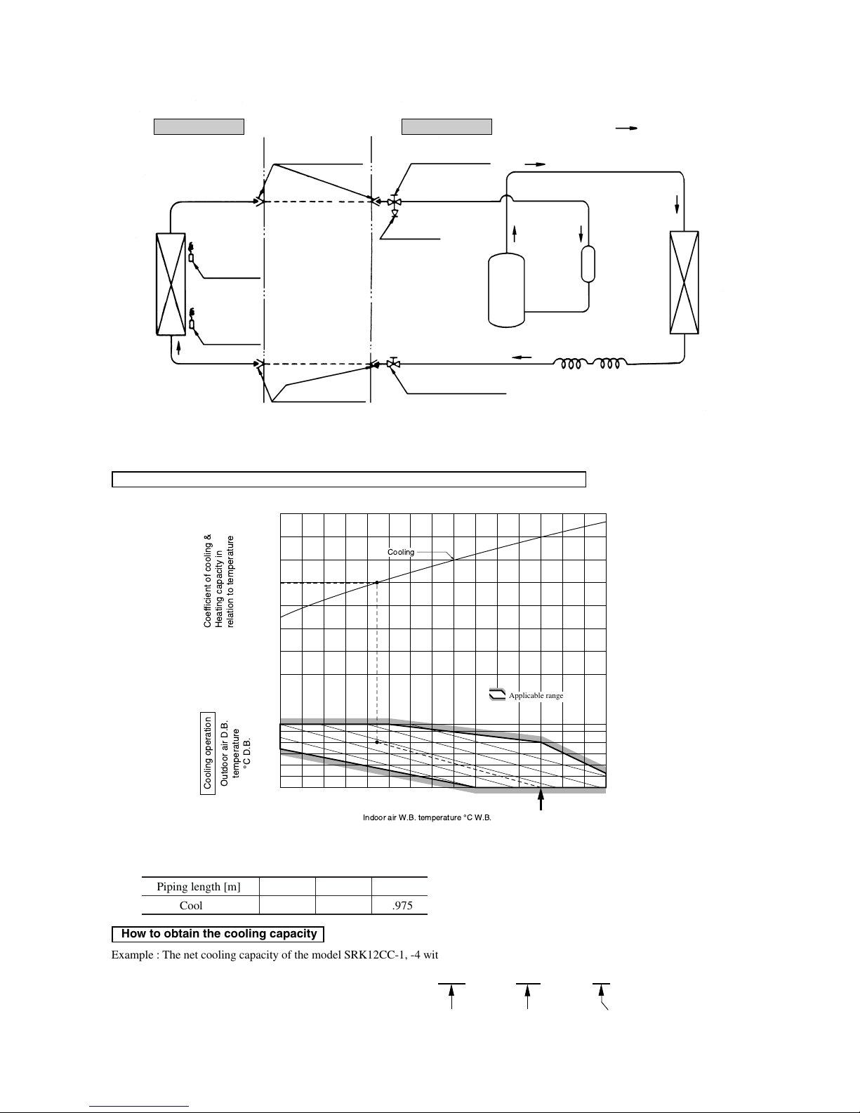
-
40
-
2.5 Selection chart
Correct the cooling capacity in accordance with the conditions as follows. The net cooling capacity can be obtained in the following way.
Net capacity = Capacity shown on specification ✕ Correction factors as follows.
(1) Coefficient of cooling capacity in relation to temperatures
(2) Correction of cooling capacity in relation to one way length of refrigerant piping
It is necessary to correct the cooling capacity in relation to the one way piping length between the indoor and outdoor units.
Heat exchanger
Heat exchanger
Room
temperature
thermistor
Flare connecting
Piping (Gas)
Piping (Liquid)
Flare connecting
(ø6.35)
(ø12.7)
Service valve (Gas)
Service valve (Liquid)
Check joint
Compressor
Suction
Accumulator
Capillary tube
Cooling cycle
Discharge
Heat
exchanger
thermistor
Indoor unit Outdoor unit
Models SRK12CC-1, 12CC-4
14 16 18 20 22
15
20
25
30
35
40
0.6
0.7
0.8
0.9
1.0
1.1
1.2
1.3
43
24
ISO-T1 Standard Condition
Indoor air W.B. temperature ¡C W.B.
Cooling
Applicable range
Coefficient of cooling &
Heating capacity in
relation to temperature
Cooling operation
Outdoor air D.B.
temperature
¡C D.B.
Piping length [m]
Cooling
7
1.0
10
0.99
15
0.975
How to obtain the cooling capacity
Example : The net cooling capacity of the model SRK12CC-1, -4 with the piping length of 15m, indoor wet-bulb temperature at 19.0˚C
and outdoor dry-bulb temperature 35˚C is Net cooling capacity = 3500 ✕ 0.975 ✕ 1.0 = 3412 w
SRK12CC-1 Length 15m
Factor by air
temperatures

-
41
-
3 ELECTRICAL DATA
3.1 Electrical wiring
Models SRK06CC-1, 06CC-4, 07CC-1, 07CC-4, 09CC-1, 09CC-4
Power source
1 Phase 220/240V 50Hz
Printed circuit board
Wireless
R-Amp
Display
Indoor unit Outdoor unit
BK Black
BL Blue
BR Brown
RD Red
OR Orange
WH White
Color symbol
Operation
Cooling
Relay symbol Control part
52C CM
Table of relay operations
Symbol Parts name Symbol Parts name
C
C
Capacitor for CM LM Louver motor
CF
I
Capacitor for FM
I
Th1,
2
Thermistor
CF
O
Capacitor for FM
O
Tr Transformer
CM Compressor motor ZNR Varistor
F Fuse 51C Motor protector for CM
FM
I
Fan motor (Indoor unit) 52C Magnetic contactor for CM
FM
O
Fan motor (Outdoor unit)
Meaning of marks
Notes (1) : denotes magentized relay × : denotes demagnetized relay
(2) Th
1 is room temperature thermistor. Th2 (the heat exchanger thermistor) is frost prevention thermistor. (for details, refer to pages 47)

-
42
-
Models SRK12CC-1, 12CC-4
Power source
1 Phase 220/240V 50Hz
Printed circuit board
Wireless
R-Amp
Display
Indoor unit Outdoor unit
Operation
Cooling
Relay symbol Control part
52C CM
Table of relay operations
Symbol Parts name Symbol Parts name
C
C
Capacitor for CM LM Louver motor
CF
I
Capacitor for FM
I
Th1,
2
Thermistor
CF
O
Capacitor for FM
O
Tr Transformer
CM Compressor motor ZNR Varistor
F Fuse 51C Motor protector for CM
FM
I
Fan motor (Indoor unit) 52C Magnetic contactor for CM
FM
O
Fan motor (Outdoor unit)
Meaning of marks
Notes (1) : denotes magentized relay × : denotes demagnetized relay
(2) Th
1 is room temperature thermistor. Th2 (the heat exchanger thermistor) is frost prevention thermistor. (for details, refer to pages 47)
BK Black
BL Blue
BR Brown
LB Light blue
Y Yellow
RD Red
OR Orange
WH White
Y/G Yellow/Green
Color symbol
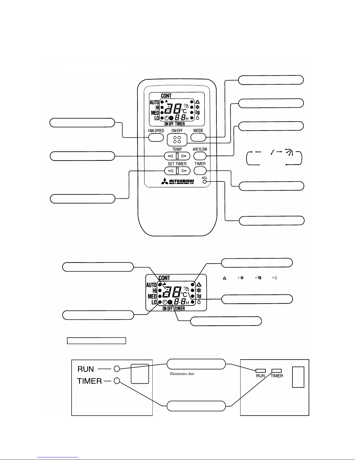
-
43
-
FAN SPEED button
Each time the button is pushed, the¡
indicator is switched over in turn.
TEMPERATURE button
This button sets the room temperature.
SET TIMER button
This button sets the ON timer and OFF
timer times.
OPERATION MODE select button
Each time the button is pushed, the¡
indicator is switched over in turn.
ON/OFF button
Press for starting operation, press again
for stopping.
AIRFLOW button
This button changes the flap mode. When
pressed, this button changes the mode in
the following order:
or
(AUTO) (SWING)
no indication
(SWING STOPPED)
TIMER button
This button changes the selection of ON
timer/OFF timer operation and normal
operation.
RESET switch
Switch for resetting microcomputer.
¡ The above illustration shows all controls, but in
practice only the relevant parts are shown.
S Indication section
TEMPERATURE Indicator
Indicates set temperature.
(Does not indicate temperature when
operation mode is on AUTO)
FAN SPEED Indicator
Indicates set air flow rate with¡lamp
OPERATION MODE Indicator
Indicates selected operation with¡lamp
AIR FLOW Indicator
Shows selected flap mode.
TIMER Indicator
Unit indication section
(Auto) (Cool) (FAN) (Dry)
¡ 06, 07, 09 type
RUN
TIMER
TIMERRUN
Illuminates during operation.
Illuminates during TIMER operation.
RUN light (green)
TIMER light (yellow)
¡ 12 type
4 OUTLINE OF OPERATION CONTROL BY MICROCOMPUTER
(1) Operation control function by remote controller
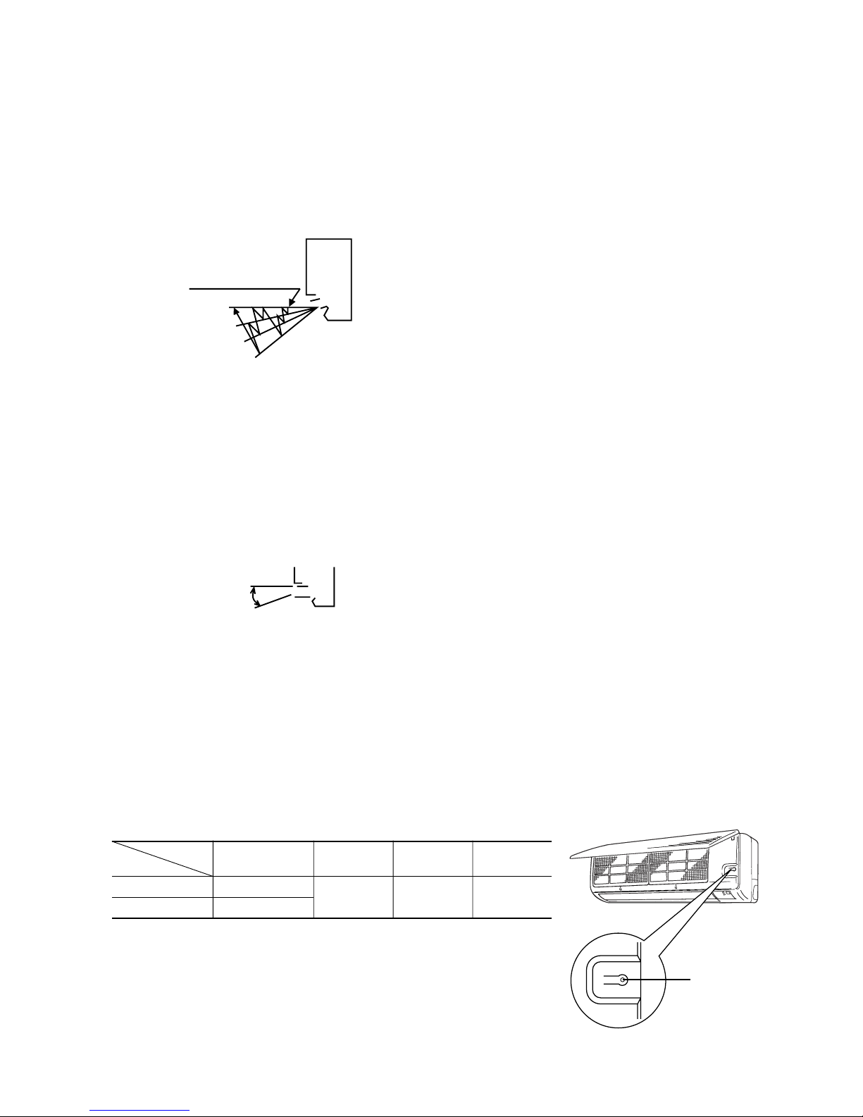
-
44
-
(2) Flap control
Control the flap by AIRFLOW button on the wireless remote controller.
(a) Natural flow (AUTO)
The flap will be automatically set to the angle of air flow best to operation.
(i) Starting time of operation
(c) Swing flap
Flap moves in upward and downward directions continuously.
(ii) When not operating
The flap returns to the position of air flow directly below, when operation has stopped.
(b) Memory flap
While the flap is operating if the AIRFLOW button is pushed once, it stops swinging at an angle.
As this angle is memorized in the microcomputer, the flap will be automatically set to the angle when next operation is
started.
¡ Recommendable stopping angle of the flap
On operating in automatic operation mode by back-up switch, functions show in the above
table are not altered, white, the other micro-computer control functions remain effective.
(3) Back-up Switch
When the remote controller batteries become weak, or if the remote controller is lost or malfunctioning, this switch may be used to
turn the unit on and off.
(a) Operation
Push the switch once to place the unit in the automatic mode. Push it once more to turn the unit off.
(b) Details of operation
The unit will go into the automatic mode in which it automatically determines, from room temperature (as detected by
thermistor), whether to go into the cooling or thermal dry modes.
Function
Room temperature
Operation mode
setting
Fan speed Flap Timer switch
Cooling About 26ºC
Thermal dry About 25ºC
Auto Natural flow Continuous
ON/OFF
Back-up switch
¡ The flap operation as shown above will be
repeated.
Stops at the level position for
one minute.
s
In case of cooling
t
and dry operation
Sway operation
Horizontal
blowing
COOL•DRY
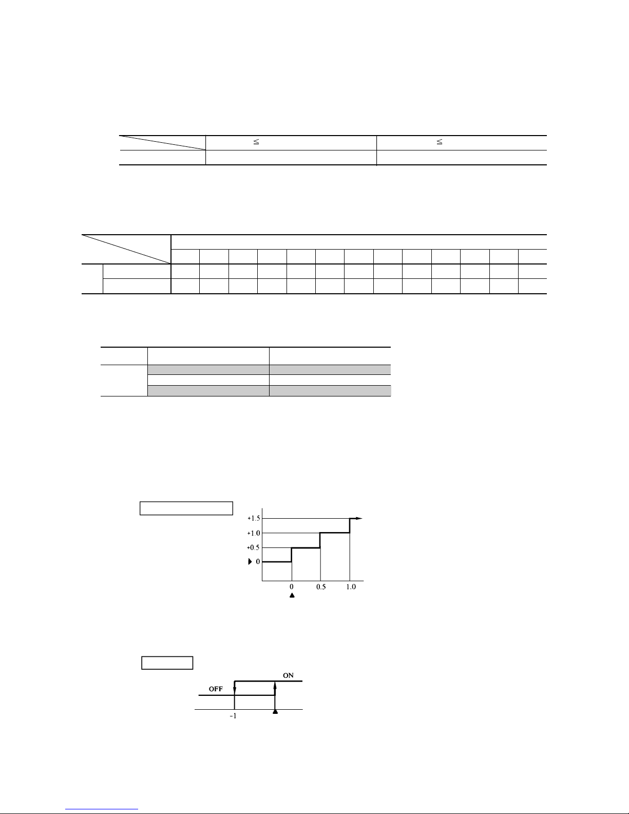
-
45
-
(5) Comfort timer settings
Temperature is checked beginning 1 hour before the set time, and the power is turned on before the timer setting as necessary to
bring the temperature to the proper level by the set time.
Operation mode Room temperature thermistor (Th1)
Operating start time (amount of time
previous to set time that operation begins)
Over 40˚C 60 mins.
Cooling Over 35˚C 30 mins.
Over 30˚C 15 mins.
Notes (1) At 5 minutes before the set time of the turn-on timer, the operation is started regardless of the temperature of the room temperature thermister.
(2) When the dry or blow operation is selected, this function is not activated.
(However, when the automatic dry operation is selected, the function described in article (1) is operated.)
(6) Timer time setting
The turn-off timer and turn-on timer can be set for up to 12 hours in units of 1 hour.
(7) Night time turn off
Placing the timer to this setting changes the temperature setting of the indoor set button as follows:
(4) AUTOMATIC operation
(a) Determination of operation mode
The blow operation of the indoor fan is carried out at the 1st speed for 20 seconds and the room temperature is checked to
determine the operation mode automatically. (When the unit is operated by the turn-on timer, the blow operation is not
carried out.)
21ºC Room temperature<26ºC 26ºC Room temperature
Operation mode Dry Cooling
(b) When switching to automatic operation during “Cooling” “Dry” or when restarting with in 1 hour after stopping with auto-
matic operation mode, the former operating mode is selected. (In this case, 20 seconds Lo operation of indoor fan is not
performed). When the previous mode is in “FAN”, operation mode is to be set by the above mentioned chart.
Wireless remote control signal (Indication)
-6 -5 -4 -3 -2 -1 ±0+1+2+3+4+5+6
Cooling 20 21 22 23 24 25 26 27 28 29 30 31 32
Thermal dry 19 20 21 22 23 24 25 26 27 28 29 30 31
Temperature
setting
(8) Temperature adjustment
a) Temperature adjustment setting may be set between 18 and 30˚C.
b) The compressor and outdoor fan and turned on and off as shown below according to the temperature setting.
Cooling
(c) Established temperature (operate by the established temperature button on remote controller).
3) During the continuous mode, the compressor runs continuously in cooling. For thermal dry, please refer to page 50.
Compressor
outdoor fan
Set temp.
Room temp.
Cooling, thermaldry
Start
Timer operation
(time)
Temperature
setting (˚C)

-
46
-
(b) Fan speed knob: AUTO
The indoor fan is automatically controlled in accordance with the difference between the room temperature (detected
by the room temperature thermistor) and the thermostat setting as shown below.
Mode
Cooling Fan
18~30˚C
Thermostat setting point Thermostat setting point
Continuous Speed 4 Speed 3
Mode
COOL FAN
Fan speed knob
AUTO See below
LOW Speed 1 (Speed 1) Speed 1 (Speed 1)
MED Speed 2 (Speed 2) Speed 2 (Speed 2)
HIGH Speed 3 (Speed 4) Speed 3 (Speed 3)
Notes (1) Please refer to page 46 regarding dry operation.
(2) Figure in ( ) shows the case that the set temperature is continuing.
(9) Fan control
(a) Fan speed change
Setting temp
Note (1) Please refer to page 46 regarding dry operation.
Note (1) Thermostat operation is performed in A, B Block. When compressor and indoor fan stop by thermostat operation within 12 minutes from start, temperature
check is performed by operating indoor fan at speed 1 for 20 seconds before finishing 12 minutes and allowing decision of next operation block.
D Block C Block B Block A Block
(10) DRY operation
(a) Choose the appropriate operation block area by the difference between room temperature and thermo-
stat setting temperature as shown below.
¡Operation block area
–2 0 +3
Room temp. – Setting temp.(deg)
(b) Start up operation
Speed 1
Speed 3
Speed 4
Speed 2
Speed 2
Speed 3
Speed 1
ON
OFF
OFF
0
3
6
912
ON
OFF
OFF
0
12
Compressor
and
outdoor fan
Set fan speed
Indoor fan
Start
Temperature check
Start
Temperature check
Compressor
and
outdoor fan
Set fan speed
Indoor fan
Operation block decision
C.D Block
A.B Block
minutes
minutes
Speed 1
20
seconds
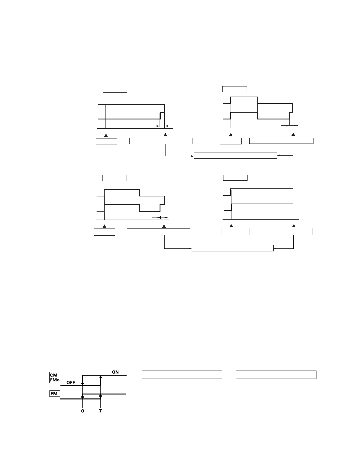
-
47
-
ON
OFF
OFF
0
4
8
ON
OFF
OFF
0
8
OFF
OFF
0
8
ON
OFF
OFF
0
3
8
(c) DRY operation
After finishing start up operation described in (b) above, thermal dry operation is performed at 8 minutes intervals, according
to the difference between room temperature and thermostat setting temperature as shown below.
Beside, 1 cycle of this operating time consists of 8 minutes, 7 cycle operation is performed then.
Compressor
and
outdoor fan
Indoor fan
D Block
Compressor
and
outdoor fan
Indoor fan
C Block
Compressor
and
outdoor fan
Indoor fan
B Block
Compressor
and
outdoor fan
Indoor fan
A Block
20 seconds
20 seconds
minutes
minutes
Start
Temperature check
Start
Temperature check
Operation block decision
20 seconds
minutes
minutes
Start
Temperature check Temperature check
Operation block decision
Start
Speed 1
Speed 1
Speed 1
Speed 1
(11) Dew condensation prevention control for cooling operation
This prevents dew condensation, in the indoor unit, from occurring.
(a) Operating condition: when 52C is kept ON for 30 min. after the unit starts operation.
(b) Operation content: forces the indoor fan to change from Speed 1 to Speed 2.
(c) Resetting condition: When 52C is off, or when dew condensation prevention control has been operating continuously for
30 minutes.
(12) Frost prevention for indoor heat exchanger [Preventing frost accumulation on the indoor heat exchanger]
During the Cooling or Dry operation in low room air temp. condition, evaporating temperature will decrease and consequently
indoor heat exchanger sometimes gets clogged with frost (or ice).
In order to prevent this trouble, compressor is stopped by under mentioned condition by indoor heat exchanger sensor (Th
2) and
timer (built into micro computer circuit) functions.
Also indoor fan is changed over to speed 1.
CM, FMO stoppage condition
1 Temperature of heat exchanger is
0˚C or lower.
2 As least 10 minutes has passed
since the compressor started.
Indoor heat exchanger
temperature (˚C)
CM, FMO re-starting condition
1 Temperature of heat exchanger is
7˚C or higher.
2 As least 3 minutes has passed since
the compressor stopped.
Set fan
speed
speed 1

-
48
-
(14) Self diagnosis function
When something abnormal happens on the outdoor unit, indoor unit fan motor and each thermistor (heat exchanger, room tempera-
ture, ) it will be indicated by flashing lamps.
(a) Abnormality of outdoor unit: When the indoor heat exchanger temperature does not fall to 25ºC or below for 40 minutes
(12 type : 20 minutes) after 5 minutes have elapsed since the compressor operation start,
the abnormality stop occurs. (The timer lamp flashes 5 times.)
(b) Abnormality of indoor fan motor: The indoor fan motor revolves at a rate under 300 rpm for 30 seconds or longer, the
RUN lamp will flash.
(c) Abnormality of heat exchanger thermistor: RUN lamp will flashing when the input temperature of the heat exchanger
thermistor measures less than –20ºC for more than 3 seconds with the
airconditioner “OFF”. (will not flashing during operation)
(d) Abnormality room temperature thermistor: RUN lamp will flashing when the input temperature of the room tem-
perature thermistor measures less than –20ºC for more than 3 seconds
with the airconditioner “OFF”. (will not flashing during operation)
Note (1) If the above abnormalities happen concurrently, the lamp will flashing in the order of item number (a) through (d) above.
(13) Three-Minute Forced Operation
When the compressor begins operating the thermal operation is not effective for 3 minutes, so operation continues as is in the
operation mode. (After 3 minutes has passed the thermal operation is effective.)
However, stopping the compressor via a stop signal or protection control has priority.
-
49
-
5 APPLICATION DATA
SAFETY PRECAUTIONS
¡ Please read these “Safety Precautions” first then accurately execute the installation work.
¡ Though the precautionary points indicated herein are divided under two headings,
WARNING and CAUTION , those
points which are related to the strong possibility of an installation done in error resulting in death or serious injury are listed in the
WARNING section. However, there is also a possibility of serious consequences in relationship to the points listed in the
CAUTION section as well. In either case, important safety related information is indicated, so by all means, properly observe
all that is mentioned.
¡ After completing the installation, along with confirming that no abnormalities were seen from the operation tests, please explain
operating methods as well as maintenance methods to the user (customer) of this equipment, based on the owner’s manual.
Moreover, ask the customer to keep this sheet together with the owner’s manual.
Cautions for installation
1 The system should be applied to places as households, residences and the like.
2 The equipment shall be installed in accordance with national wiring regulations.
3 The connection to the fixed wiring of the mains supply must be made via a double pole isolating switch with a contact gap of at
least 3mm in each pole.
4 When the outdoor unit has a possibility of being overturned or being displaced and fall from its original installation position, the
outdoor unit should be fixed in its position by use of anchor bolts or wires.
WARNING
¡ This system should be applied to places as households, residences and the like. Application to inferior environment such as
engineering shop could cause equipment malfunction.
¡ Please entrust installation to either the company which sold you the equipment or to a professional contractor. Defects from improper
installations can be the cause of water leakage, electric shocks and fires.
¡ Execute the installation accurately, based on following the installation manual. Again, improper installations can result in water
leakage, electric shocks and fires.
¡ For installation, confirm that the installation site can sufficiently support heavy weight. When strength is insufficient, injury can result
from a falling of the unit.
¡ For electrical work, please see that a licensed electrician executes the work while following the safety standards related to electrical
equipment, and local regulations as well as the installation instructions, and that only exclusive use circuits are used.
Insufficient power source circuit capacity and defective installment execution can be the cause of electric shocks and fires.
¡ Accurately connect wiring using the proper cable, and insure that the external force of the cable is not conducted to the terminal
connection part, through properly securing it improper connection or securing can result in heat generation or fire.
¡ Take care that wiring does not rise upward, and accurately install the lid/service panel.It’s improper installation can also result heat
generation or fire.
¡ When setting up or moving the location of the air conditioner, do not mix air etc. or anything other than the designated refrigerant
(R22) within the refrigeration cycle.
Rupture and injury caused by abnormal high pressure can result from such mixing.
¡ Always use accessory parts and authorized parts for installation construction. Using parts not authorized by this company can result
in water leakage, electric shock, fire and refrigerant leakage.
¡ Ventilate the work area when refrigerant leaks during the operation.
Coming in contact with fire, refrigerant could generate toxic gas.
¡ Confirm after the foundation construction work that refrigerant does not leak.
If coming in contact with fire of a fan heater, a stove or movable cooking stove, etc., refrigerant leaking in the room could generate
toxic gas.
CAUTION
¡ Execute proper grounding. Do not connect the ground wire to a gas pipe, water pipe, lightning rod or a telephone ground wire.
Improper placement of ground wires can result in electric shock.
¡ The installation of an earth leakage breaker is necessary depending on the established location of the unit.
No installing an earth leakage breaker may result in electric shock.
¡ Do not install the unit where there is a concern about leakage of combustible gas.
The rare even of leaked gas collecting around the unit could result in an outbreak of fire.
¡ For the drain pipe, follow the installation manual to insure that it allows proper drainage and thermally insulate it to prevent
condensation. Inadequate plumbing can result in water leakage and water damage to interior items.
¡ Install the outdoor unit so that the aluminum fins on the air heat exchanger cannot be touched. Failure to observe this may result in
injury.

-
50
-
5.1 Selection of location for installation
(1) Indoor unit
1 Where there is no obstructions to the air flow and where the
cooled air can be evenly distributed.
2 A solid place where the unit or the wall will not vibrate.
3 A place where there will be enough space for servicing.
(Where space mentioned below can be secured)
4 Where wiring and the piping work will be easy to conduct.
5 The place where receiving part is not exposed to the direct
rays of the sun or the strong rays of the street lighting.
(2) Outdoor unit
1 A place where good air circulation can be obtained and where
rain, snow or sunshine will not directly strike the unit.
2 A place where discharged hot air or unit’s operating sound
will not be a nuisance to the neighborhood.
3 A place where servicing space can be secured.
4 A place where vibration will not be enlarged.
6.5 cm
5cm
10 cm
1.5 cm
(12 type : 4 cm)
Left
side
Right
side
Air inlet
Service
space
()
Air inlet
Air
Outlet
Note (1) If the wall is higher than 1.2 m or a ceiling is
present, distances larger than indicated in the above
table must be provided.
300
100
250
100
r
H
One way piping length (R) 15 m
Outdoor
unit is lower
5 m
Outdoor unit
is higher
5 m
Vertical height
difference (H)
unit : mm
Option parts Q'ty
a Sealing plate 1
b Sleeve 1
c Inclination plate 1
d Putty 1
e Drain hose (extention hose) 1
f 1
Piping cover (for insulation of
connection piping)
(3) Limitations for one way piping length and vertical height difference.
Necessary tools for the installation work
1 Plus headed driver
2 Knife
3 Saw
4 Tape measure
5 Hammer
6 Spanner wrench
7 Torque wrench
8 Hole core drill (65mm in diameter)
9 Gas leak detector
10 Flaring tool set
11 Vacuum pump
12 Wrench key (Hexagon) [4m/m]
Standard accessories (Installation kit) Q'ty
1 1
2
Tapping screws (for installation board)
5
3 Battery (UM-4, 1.5V) 2
Installation board (Attached to the
rear of the indoor unit)
15.7 to 49.0N · m
(1.6 to 5.0kgf · m)
( )
(12 type: 4)
(12 type : 200)
(12 type :
600)
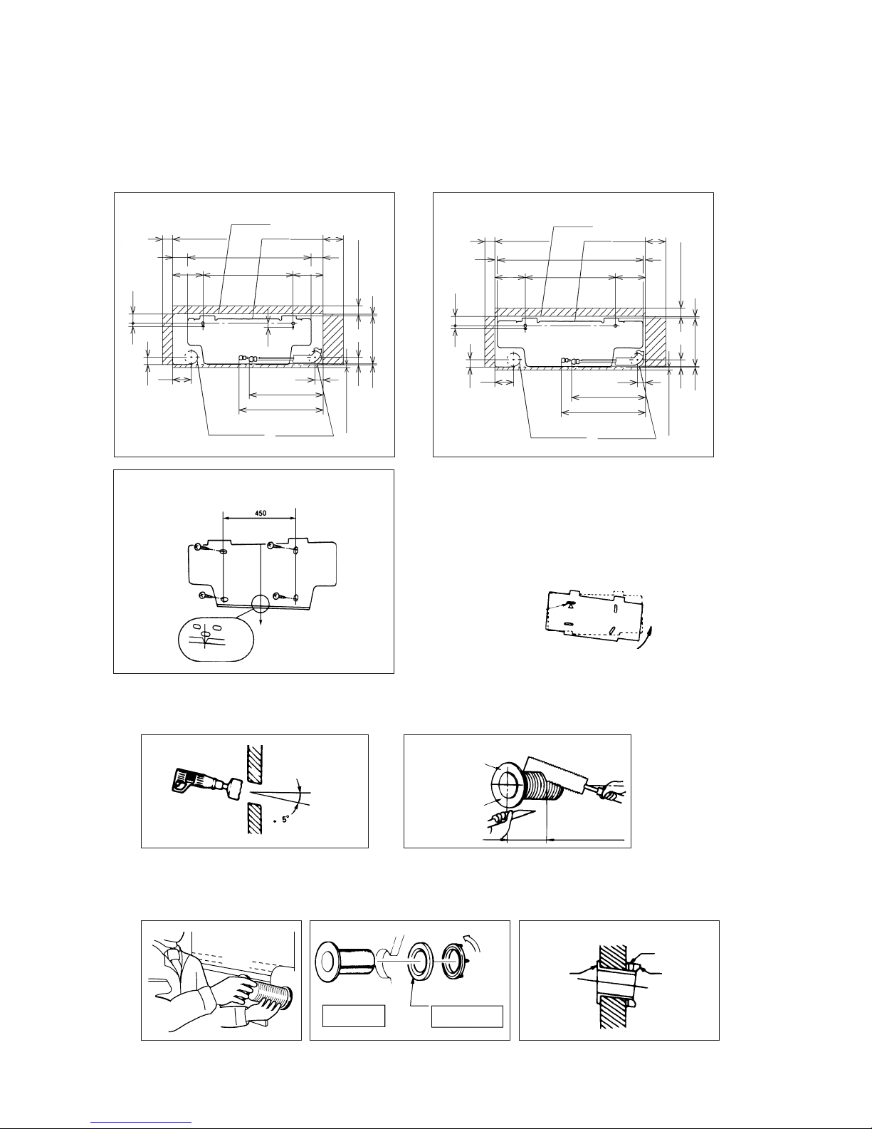
-
51
-
1 Fixing of installation board
5.2 Installation of indoor unit
(1) Installation if installation board
(Inserting sleeve)
Indoor side Outdoor side
Turn to
tighten
Paste
View of sleeve when installed
Inclined
flange
Sealing
plate
Sleeve
Indoor side Outdoor side
(*Sleeve + *Inclined + *Sealing plate)
3 Install the sleeve
Lock for the inside wall structures (Intermediate support
or pillar) and fairly install the unit after level surface has
been checked.
Tapping Screws
Mating make for level surface
(Horizontallty)
50
75 615
450
60
100
40
Gas pipe 370
Liquid pipe 420
92
Ø65
Ø65
9
65
236.54.5
36
36
15
19
15
46
Service space
Position for the
hole in the wall
Position for the
hole in the wall
Service space
Service space
Service
space
Indoor unit
Installation
board
150
150
Relation between setting plate and indoor unit
¡ 06, 07, 09 type
Relation between setting plate and indoor unit
50
760
450
15
100
51
Gas pipe 390
Liquid pipe 440
67
ø65
ø65
9
40
2606
36
36
15
15
46
Service space
Position for the
hole in the wall
Position for the
hole in the wall
Service space
Service space
Service
space
Indoor unit
Installation
board
170
170
15
¡ Adjustment of the installation board in the
horizontal direction is to be conducted with
four screws in a temporary tightened state.
¡ Adjust so that board will be level by turning
the board with the standard hole as the
center.
Standard hole
¡ 12 type
Note (1) Drill a hall with incline of 5 degree from
indoor side to outdoor side.
Indoor side Outdoor side
Cut off the sleeve
collar in case of
drawing piping
out to rear.
Cut off the sleeve
collar that can be
seen from beneath
the unit.
Wall thickness
+ 1.5 cm
1 Drill a hole with ø65 whole core drill 2 Adjusting sleeve length
(2) Drilling of holes and fixture sleeve (Option parts)
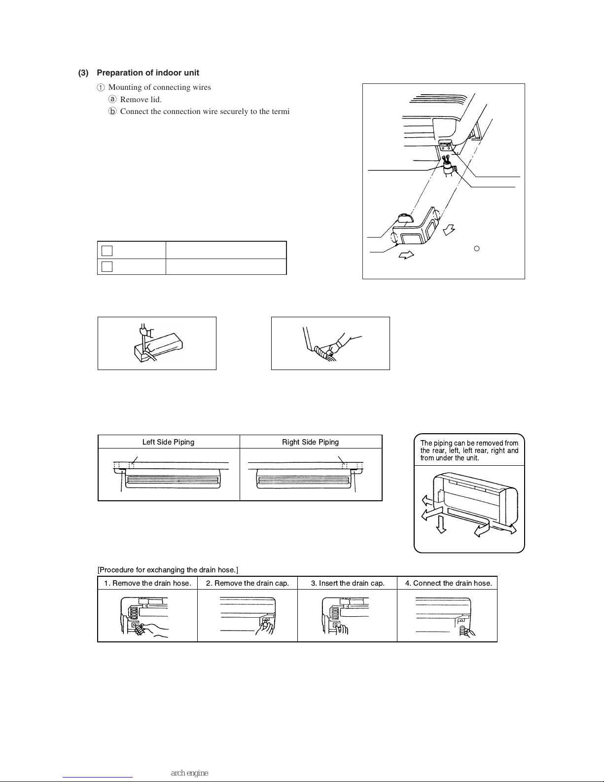
-
52
-
Pipe
Drain hose
(3) Preparation of indoor unit
1 Mounting of connecting wires
a Remove lid.
b Connect the connection wire securely to the terminal block.
¡ Affix the connection wire securely to the terminal block.
If the wire is not affixed completely, contact will be poor,
and it is dangerous as the terminal block may heat up and
catch fire.
¡ Take care not to confuse the terminal numbers for indoor
and outdoor connections.
¡ Affix the connection wire using the wiring clamp.
c Attach the lid.
Terminal Block
Wiring Clamp
Connecting Wiring
Cover
Lid
Pull the part marked
while pushing
its part in the direction of allow so as
to dismount it. (Dismount or detach it
for each side).
2 Shaping the pipe 3 Taping of the exterior
¡ Hold the bottom of the pipe and change its direc-
tion before stretching it and shaping it.
¡ Tape only the portion that runs through the wall.
Always tape the crossover wires with the pipe.
4 Cautions when piping from the left and the rear center of the unit
[ Top View ]
¡ Loosen and remove the
spring-type clamp.
¡ Remove with your hand
or a pair of pliers.
¡ Use a hexagonal wrench to
correctly insert the drain
cap which was removed in
2.
Caution: Be careful because if the cap is not inserted property, water leak
may occur.
¡ Loosen the spring-type clamp
and securely insert the drain
hose.
Caution: Be careful because if
the cap is not inserted properly,
water leak may occur.
Right
Rear
Under
Left rear
Left
Right rear pipingLeft rear piping
Left side piping Right side piping
Left Side Piping Right Side Piping
The piping can be removed from
the rear, left, left rear, right and
from under the unit.
For power supply, indoor outdoor
For power supply, indoor outdoor
1 Brown
2 Blue

-
53
-
Wall
Gutter
Pipes storage area
¡ When conducting the central rear piping, use a nipper to cut out
knock-out holes in the installation board.
¡ Do not place the power supply cords
above the gutter, because the air conditioner is structured in a way where
condensation on the back side is collected in to the drain pan before
drainage.
Indoor unit
Hook (2 locations)
Installation
board
Instalation
board
Indoor unit
base lower hook
Wall
Installing steps
Declining slope
Inverted slipe
Trap
Catch position marks on the bottom
of the indoor unit's base
Lid (right)
¡ Do not make traps in the drain hose line.
5 Securing the indoor unit to the installation board
a To remove the indoor unit from the mounting plate.
¡ Remove the left and right lids.
¡ Use your fingers to pull down the catches (left and right) at the bottom of the indoor unit's base, indicated by the catch
position marks. (The catches on the indoor unit's base are released from the mounting plate.)
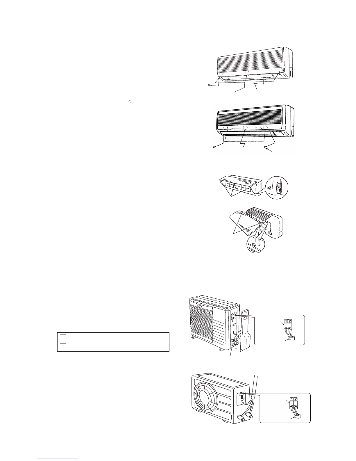
-
54
-
(4) Removal and installation of the front panel
1 Removal
¡ Remove fixing screws (2 places).
¡ Lift the lower part of panel toward you, then remove the
panel by pushing up its upper portion.
2 Installation
¡ Remove the air filter without fall.
¡ Put the front panel on the main unit.
¡ Push the portion shown by
in the below illustration
rearward.
¡ Tighten fixing screws (2 places).
¡ Set the air filter.
(5) Open/close and detachment/attachment of suction grille
1 To open, pull the grille at both ends of lower part and release
latches, then pull up the grille until you feel resistance. (The
suction grille stops at approx. 60˚ open position.)
2 To close, hold the grille at both ends of lower part to lower
downward and push it slightly until the latch works, then
push the center portion slightly.
3 To remove, pull up the grille to the position shown in below
illustration and pull it toward you.
4 To install, insert the suction grille arm into the slot on the
front panel from the position shown in below illustration,
hold the panel at both ends of lower part, lower it downward
slowly, then push it slightly until the latch works and further
push the center portion slightly.
For power supply, indoor outdoor
For power supply, indoor outdoor
1 Brown
2 Blue
5.3 Installation of outdoor unit
1 Make sure that the unit is stable in installation. Fix the unit to
stable base.
2 Perfrom wiring, making wire terminal numbers conform to
terminal numbers of indoor unit terminal block.
Claw (3 places)
Attaching arm
Push these portions
Fixing screw
¡ 06, 07, 09 type
Wiring clamp
Terminal block
Interconnecting wire
¡ 06, 07, 09 type
¡ 12 type
Terminal block
Interconnecting wire
¡ 12 type
Push these portions
Fixing screw

-
55
-
(3) Air purge
1 Tighten all flare nuts in the pipings both indoor and outside wall so as not to cause leak.
2 Connect service valve, charge hose, manifold valve and vacuum pump as is illustrated below.
3 Open manifold valve handle Lo to its full width, and perform vacuum or evacuation.
Continue the vacuum or evacuation operation for 15 minutes or more and check to see that the vacuum gauge reads – 0.1
MPa (– 76 cmHg).
4 After completing vacuum operation, fully open service valve (Both gas and liquid sides) with hexagon headed wrench.
5 Check for possible leakage of gas in the connection parts of both indoor and outdoor.
♦ Additional refrigerant charge
5.4 Connection of refrigerant pipings
(1) Preparation
Keep the openings of the pipes covered with tapes etc. to prevent dust, sand, etc. from entering them.
Manifold
Valve
-76 cm Hg
Handle Lo
(pressure)
Charge hose
Stop valve
(Two-way valve)
Service port
Stop valve
(Three-way
valve)
Compound
(Gauge)
Pressure
gauge
Handle Hi
(pressure)
Charge hose
Vacuum pump
¡ Remove the flared nuts.
(on both liquid and gas sides)
¡ Remove the flared nuts.
(on both liquid and gas sides)
¡ Install the removed flared nuts to the pipes to be con-
nected, then flare the pipes.
Dimension A
Liquid side
(f6.35): 9-9.5 dia
Gas side
(f9.52): 13.2-14 dia
(f12.7): 16.2-17 dia
Press
Remove
Remove
(Do not
turn)
1 Indoor unit side 2 Outdoor unit side
¡ Specified torquing value:
Liquid side (ø6.35) : 15.7~19.6N·m (1.6~2kgf·m)
Gas side (ø9.52) : 29.4~39.2N·m (3.0~4.0kgf·m)
(ø12.7) : 39.2~49N·m (4.0~5.0kgf·m)
¡ Use one more spanner to fix the valve.
¡ Specified torquing value:
Liquid side (ø6.35) : 15.7~19.6N·m (1.6~2kgf·m)
Gas side (ø9.52) : 29.4~39.2N·m (3.0~4.0kgf·m)
(ø12.7) : 39.2~49N·m (4.0~5.0kgf·m)
1 Indoor unit side 2 Outdoor unit side
¡ Connect firmly gas and liquid side
pipings by Torque wrench.
¡ Connect firmly gas and liquid side
pipings by Torque wrench.
¡ Always use a Torque wrench and back up spanner to tighten the flare nut.
(2) Connection of refrigerant piping
¡ 06, 07, 09 type
When refrigerant piping exceeds 7.5m conduct additional refrigerant charge after refrigerant sweeping.
7.5m over 10m:Additional charge amount per meter = 10g/m
10m over 15m:Additional charge amount per meter=30g/m
[Example]
How much amount of additional charge for 15m piping?
(10 – 7.5)m × 10g/m+(15-10)m×30g/m=175g 175g for additional charge
Spanner
for fixing
the piping)
Torque
wrench
When refrigerant piping exceeds 10m conduct additional refrigerant charge after refrigerant sweeping.
Additional charge amount per meter = 20g/m
[Example]
How much amount of additional charge for 15m piping?
(15 – 10)m × 20g/m = 100g 100g for additional charge
¡ 12 type
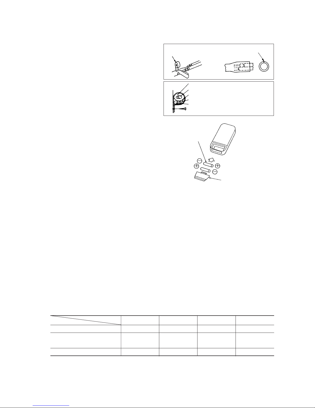
-
56
-
Vinyl tape
To cover the connecting portion with insulation materials, cut upper portion and then seal
it with insulation materials.
Cover the exterior portion with covering tape and shape the piping so it
will match the contours of the route
that the piping to take. Also fix the
wiring and pipings to the wall with
clamps.
Insulation
Refrigerant piping
Electrical wiring
Covering tape
Drain hose
Tapping screw
Cover
3 Battery
(4) Insulation of connecting portion
1 Cover the connection portion of the refrigerant piping
with the pipe cover and seal them.
If neglecting to do so, moisture occurs on the piping and
water will drip out.
2 Finishing and fixing
a
Tie up the piping with wrapping tape, and shape it so that it
conforms to which the pipe is attached.
b Fix them with clamps as right figure.
5.5 Installation of remote control switch
(1) Mounting method of battery
¡Uncover the remote control switch, and mount the batteries
(UM-4 × 2 pieces) in the body regularly.
(Fit the poles with the indication marks, , & . without fail)
5.6 Earthing work
¡Earth work shall be carried out without fail in order to prevent electric shock and noise generation.
¡The connection of the earth cable to the following substances causes dangerous failures, therefore it shall never be done.
City water pipe, Town gas pipe, TV antenna, lightning conductor, telephone line, etc.
5.7 Trial run and operation
1 Conduct trial run after confirming that there is no gas leaks.
2 When conducting trial run set the remote controller thermostat to continuous operation position. However when the power
source is cut off or when the unit’s operation switch is turned off or was turned to fan operation position, the unit will not go
into operation in order to protect the compressor.
3 Insert in electric plug into the electric outlet and make sure that it is not loose.
a When there is something wrong with the electric outlet and if the insertion of the electric plug is insufficient, there may
occur a burn out.
b It is very important to be careful of above when pulgging in the unit to an already furnished electrical outlet.
4 Explain to the customer on the correct usage of the air conditioner in simple layman’s terms.
5 Make sure that drain flows properly.
6 Standard operation data.
Note (1) The data are measured at following conditions
Ambient air temperature
Indoor side: 27°C DB, 19°C WB
Outdoor side: 35°C DB, 24°C WB
Item
Model
SRK06CC-1, 06CC-4 SRK07CC-1, 07CC-4 SRK09CC-1, 09CC-4 SRK12CC-1, 12CC-4
Low pressure MPa (kgf/cm2) 0.4 ~ 0.5 (4 ~ 5) 0.4 ~ 0.5 (4 ~ 5) 0.4 ~ 0.5 (4 ~ 5) 0.4 ~ 0.5 (4 ~ 5)
12 – 17 12 – 17 11 – 16 13 – 17
Running current (A) 4.3/4.6 4.3/4.7 4.4/4.8 6.4/6.8
Temp. difference between return
air and supply air (˚C)
220/240V

-
57
-
5.8 Precautions for wireless remote controller installation and operation
(1) Wireless remote controller covers the following distances:
(a) When operating facing the air-conditioner:
Notes (1) The remote controller is correctly facing the sensing
element of the air conditioner when being manipulated.
(2) The typical coverage is indicated (in the left illustration).
It may be more or less depending on the installation.
(3) The coverage may be less or even nil. If the sensing
element is exposed to strong light, such as direct
sunlight, illumination, etc., or dust is deposited on it or
it is used behind a curtain, etc.
less
or
or less
5 m or less
Wireless remote
controller
5 m or less
or less
(b) When manipulating the remote controller mounted on a wall:
Make sure that it works normally (i.e., transmission/reception signal is
audible) before mounting.
Receiver
Remote control
available in this area.
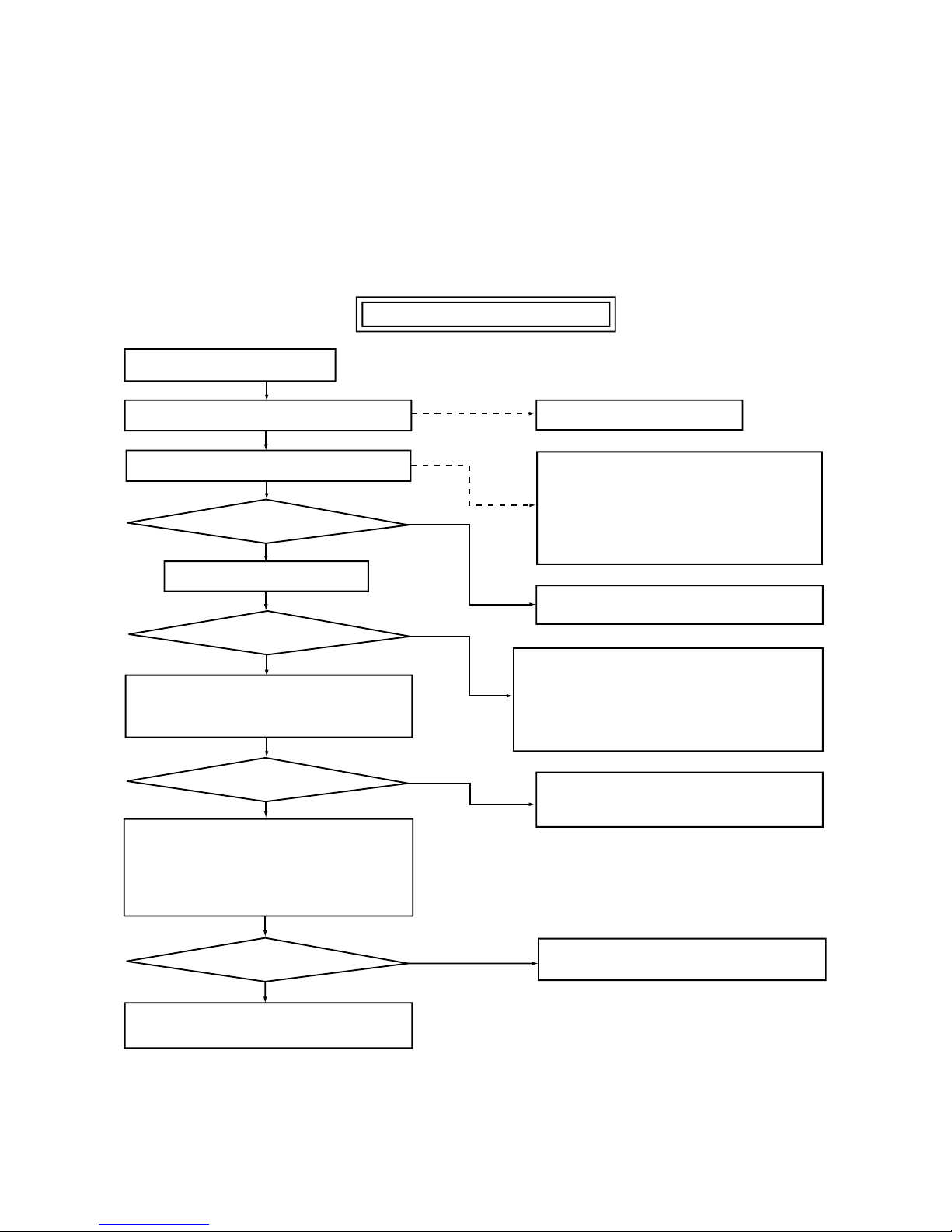
-
58
-
6 MAINTENANCE DATA
6.1 Trouble shooting
(1) Trouble shooting to be performed prior to exchanging PCB, (Printed circuit board) [Common to all models]
All the models described in this chapter are controlled by a microcomputer. When providing maintenance service to customers it
is necessary to understand the function controlled by a micro computer thoroughly, so as not to mistakenly identify correct opera-
tions as mis-operations. It is also necessary to perform the following simple checks before conducting detailed checks or exchang-
ing printed circuit board.
Before exchanging Printed circuit board
Claim call from the user
Ascertain the nature of the claim.
Ascertain the operation status.
Does the trouble occur again?
Is this nonsense claim?
Operate the unit.
Does the trouble occur again?
Temporarily turn off the power source and
turn it on again in about 1 min. and turn the
unit on again.
YES
No
YES
YES
Does the trouble occur again?
Disconnect connectors and connect them
again.
Operate the unit again after confirming that the fuse
and the varistor equipped on PCB does not burn out.
Carry out checks according to detailed
check process (See later page)
Unit did not cool, etc.
¡ Is the power on?
¡ Is the thermostat setting correct?
(Not too high?)
¡ Is the unit in a timer operation?
¡ Does user understand function?
etc.
¡ Explain the function of the unit to user.
No need for PCB change
Check further the status when the trouble occured
(such as the timer of occurence, power failures, thunder, use status of other electrical appliances, etc).
Clarify the reason for the problem and explain it thoroughly to the user.
No need for PCB change
Microcomputer runaway due to power source
conditions is a possible cause.
No need for PCB change
The cause is defective connector contact.
YES
No
No
No

-
59
-
(2) Indication of Self Diagnosis (Indoor unit)
TIMER lamp
is lights
continuously.
RUN lamp is flashing.
(1 Time flash.)
RUN lamp is flashing.
(2 Time flash.)
RUN lamp is flashing.
(6 Time flash.)
TIMER lamp is flashing.
(5 Time flash.)
Connect of Defect
Abnormality of heat
exchanger thermistor.
Abnormality of room
temperature thermistor.
Abnormality of indoor
fan motor.
Abnormality of outdoor
unit.
Place of defect
¡ Disconnection of heat exchanger thermistor.
¡ Disconnection of room temperature
thermistor.
¡ Fan motor is defective.
¡ Printed circuit board is defective.
¡ Compressor is defective.
¡ Capacitor is defective.
¡ Gas is short.
RUN lamp is
lights
continuously.
Abnormality of thermistor Disconnection of thermistor and defective connection of connector
(Disconnection)
(Short circuit)
Resistance value
(kΩ)
Temperature (°C)
Is connection to connector
good?
Is thermistor resistance
value normal?
Replace PCB.
Repair connector.
Replace thermistor.
No
No
Ye s
Ye s
Chart for thermistor temperature
resistance characteristics
(3) Troubleshooting
Abnormality of outdoor unit [Compressor malfunction of insufficient gas (refrigerant)]
Abnormality of indoor fan motor (Fan motor defective, printed circuit board defective)
No
No
Ye s
Ye s
Ye s
Ye s
Ye s
No
No
Replace protective device.
Replace capacitor.
Is capacitor normal?
Insufficient gas.
Replace compressor.
Is protective device normal?
Does compressor operate?
Clogging of capillary tube. etc.
Is abnormality the same after
gas charging?
Is refrigerant circulation
volume normal?
No
No
Ye s
Ye s
The fan motor is defective.
Repair the connector.
Is voltage being applied to the
fan motor?
The indoor circuit board
is defective.
Is the connector connection
good?

-
60
-
(4) Trouble Diagnostic Procedures
Unit malfunctions or
does not stop.
Replace PCB.
Microcomputer rarely
mis-starts even during
times or power supply
or power failure, but, it
can sometimes occur
during those times. If it
occurs, check the operation, when the result is
positive then proceed as
normal.
Runaway of micro-
computer
Remove receptacle.
Insert it after 3 min.
and operate.
No change.
Normal operation.
Indoor lamp of
indoor unit does not
illuminate.
Check receptacle voltage.
Check if PCB fuse is blown.
Check varistor.
Check transformer secondary
voltage
Replace PCB.
Replace fuse.
Replace varistor.
Replace transformer
No
No
Outdoor fan does not
operate.
Check voltage with fan
connector.
Replace PCB.
Check capacitor.
Replace fan motor.
Replace capacitor.
Abnormal
Ye s
Normal
Unit Thermistor Operation
Function
Short circuit Broken connection
Cooling
Cooling
Indoor unit
Room temperature
thermistor
(1)
(Th1) except
for “continuous” thermal
setting.
Cooling will not operate
¡ FM
I : continuous operation
¡ CM,FM
o: stopped
Cooling will operate
¡ Heat exchanger frost preventer begins to operate
¡ Cools alternately for 10 minutes, stopping for 3
minutes.
(5) Trouble shooting chart for the room temperature thermistor (Th1), heat exchanger thermistor (Th2)
Continuous Cooling operation
¡ Cannot be turned ON/OFF by thermostat
¡ When FMI is on. “AUTO” is continuously
Hi
Heat exchanger
thermistor (Th
2)
Cooling will not operate.
Note (1) When the room temperature thermistor (Th
1) will not operate normally. Cooling operation may be run continuously by putting the thermostat setting on
“CONTINUOUS”
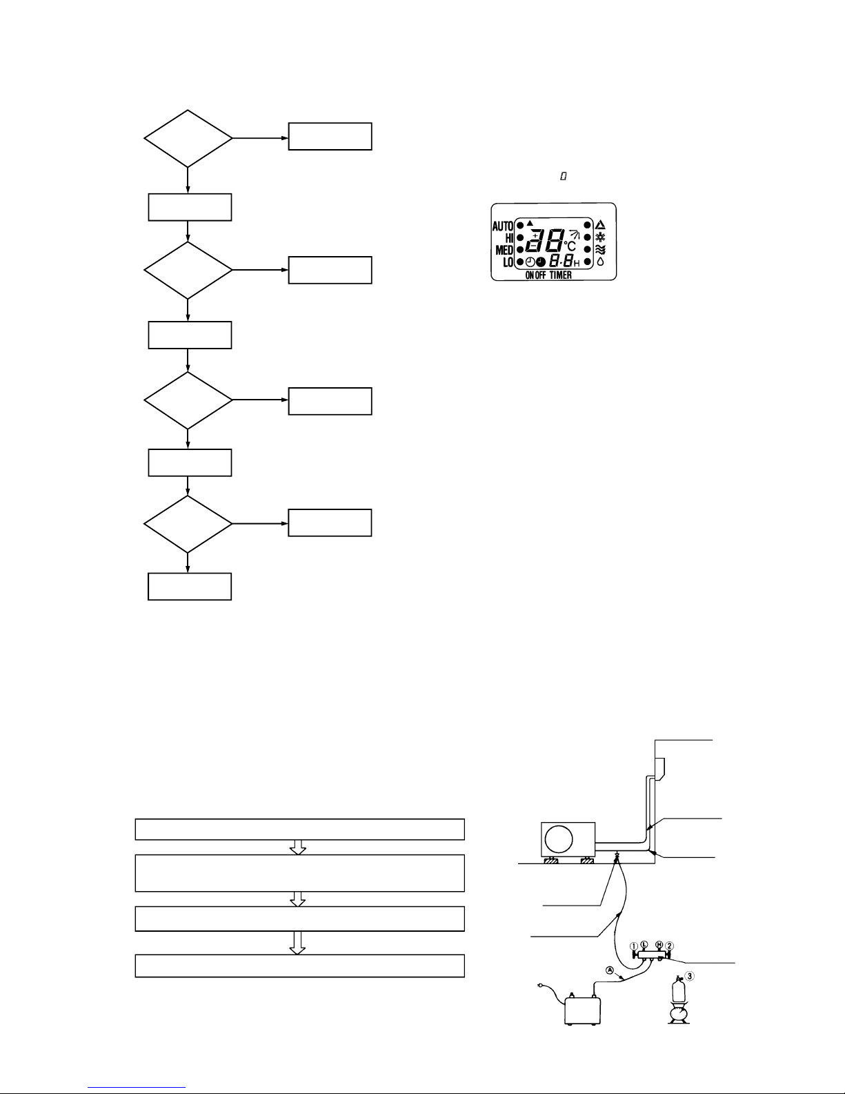
-
61
-
6.2 Servicing
(1) Evacuation
The evacuation is an procedure to purge impurities ...... noncondensable gas, air, moisture from the refrigerant equipment by using
a vacuum pump. Since the refrigerant R22 is very insoluble in water, even a small amount of moisture left in the refrigerant
equipment will freeze, causing what is called water clogging.
¡ Evacuation procedure
(a) Check to ensure that there is no internal pressure in the unit. If there is an internal pressure, it
should be relieved through the check joint.
(b) Connect the service hoses of the gauge manifold to the check joint of the gas & liquid piping.
(c) Connect a vacuum pump to the charge hose A . Repeat evacuation in the following sequence.
(6) How to make sure of remote controller
(1)
Is remote
controller
normal?
YES
Again pushing
operating switch
Operating the
unit?
NO
Does operating
backup switch
YES
Replace the
display
Remote controller
defects
Abnormal is not
fount
It is normal
Remote
controller defects
NO
NO
YES
NO
CONT
Note (1) How to check the remote controller
(a) Press the reset switch of remote controller.
(b) If the almost normal if entire display of remote control-
ler is shown after
indication.
Liquid side
Gas side
Check joint
Service hose
Charge hose
Vacuum
pump
Refrigerant
cylinder
Gauge
manifold
Stop the vacuum pump.
Notes (1) Do not use the refrigerant pressure to expel air.
(2) Do not use the compressor for evacuation.
(3) Do not operate the compressor in the vacuum condition.
Start the vacuum pump
Operate the vacuum pump for more than 15 minutes after –0.1MPa
(–76 cmHg) is indicated.
Close low pressure valve 1 of gauge manifold.
Operating the unit?
Control unit defects
YES
Operating the
unit by remote
controller?

-
62
-
6.3 Power supply remote operation
When the remote part on indoor unit PCB is modified, the air conditioner is turned ON-OFF by power supply ON-OFF operation
without using remote control switch.
After the power supply remote operation, the operation contents can be modified by the remote controller.
(1) Operation contents
(2) Modification method
Solder the high-speed switching diode (manufacturer: Matsushita, Manufacture type No.: MA165) to “Remote” part on the PCB
in the direction as shown in the diagram below.
This diagram shows SRK06CC-1 and although the other units have different layout on the PCB, their concepts are same.
Power supply ON
3-minute timer
operation
Power supply OFF
Air conditioner
STOP
Start operation
AUTO
COOL: 26˚C
DRY: 25˚C
AUTO
AUTO
Continuous
Operation change
Set temperature
Air capacity change
Flap
Timer
(2) Refrigerant charge
(a) Discharge refrigerant entirely from the unit and evacuate the unit.
Note: Addition of refrigerant without evacuation is unreasonable, because it will result in low charge or overcharge.
(b) Keep the gauge manifold and connect a refrigerant cylinder to the unit.
(c) Record the weight of the refrigerant cylinder on the balance. This is necessary for making sure of the charged refrigerant
amount.
(d) Purge air from the charge hose A .
Firstly loose the connecting portion of the charge hose A at the gauge manihold side and open the valve 3 for a few seconds,
and then immediately retighten it after observing that gas is blow out from the loosened portion.
(e) Open the valve 1 and 3 after discharging air from the charge hose A , then the gas refrigerant begins flowing from the
cylinder into the unit. Be sure to erect the refrigerant cylinder upright to let gas refrigerant flow into the unit.
(f) When refrigerant has been charged into the system to some extent, refrigerant flow becomes stagnant, when that happens,
start the compressor in cooling cycle until the unit is filled with gas to the specified weight.
(g) Making sure of the refrigerant amount, close the valve 3.
(h) Disconnect the charge hose from the unit. Cover the valve ports of the refrigerant piping with caps and tighten them securely.
(i) Check for gas leakage applying a gas leak detector along the piping line.
(j) Start the air conditioner and make sure of its operating condition ...... high side and low side pressures and temperature
difference between suction air and outlet air.

-
63
-
CONTENTS
1. GENERAL INFORMATION ............................................................................. 64
1.1 Specific features ....................................................................................... 64
1.2 How to read the model name ................................................................... 64
2. SELECTION DATA .......................................................................................... 65
2.1 Specifications ........................................................................................... 65
2.2 Range of usage & limitations .................................................................. 67
2.3 Exterior dimensions ................................................................................. 67
2.4 Piping system ........................................................................................... 68
2.5 Selection chart .......................................................................................... 69
3. ELECTRICAL DATA ........................................................................................ 70
3.1 Electrical wiring ........................................................................................ 70
4. OUTLINE OF OPERATION CONTROL BY MICROCOMPUTER ................... 71
5. APPLICATION DATA ...................................................................................... 77
5.1 Selection of location for installation ....................................................... 78
5.2 Installation of indoor unit......................................................................... 79
5.3 Installation of outdoor unit ...................................................................... 81
5.4 Refrigerant piping ..................................................................................... 81
5.5 Test run ...................................................................................................... 83
5.6
Precautions for wireless remote controller installation and operation
..... 83
6. MAINTENANCE DATA .................................................................................... 84
6.1 Trouble shooting ....................................................................................... 84
6.2 Servicing.................................................................................................... 87
6.3 Power supply remote operation .............................................................. 88
MODELS SRK50CA SRK56CA SRK56CA-4

-
64
-
1 GENERAL INFORMATION
1.1 Specific features
The “Mitsubishi Daiya” room air-conditioner: SRK series are of split and wall mounted type and the unit consists of indoor unit and
outdoor unit with refrigerant precharged in factory. The indoor unit is composed of room air cooling equipment with operation control
switch and the outdoor unit is composed of condensing unit with compressor.
(1) Remote control flap
The flap can be automatically controlled by operating wireless remote control.
¡ AUTO (Natural flow) : Flap operation is automatically control.
¡ Swing : This will swing the flap up and down.
¡ Memory flap : Once the flap position is set, the unit memorizes the position and continues to operate at the same
position from the next time.
(2) Automatic Operation
When the remote control switch is set on “auto”, it will either automatically decide operation mode such as cooling, and thermal
dry, or operate in the operation mode before it has been turned to automatic control.
(3) Self diagnosis Function
We are constantly trying to do better service to our customers by installing such judges that show abnormality of operation as
follows.
1.2 How to read the model name
Example :
SR C 50 C A
Series No.
Cooling only type
Product capacity
Outdoor unit
Split type room
air-conditioner
Series No.
Product capacity
Wall mounted type
Split type room
air-conditioner
Indoor Unit
SR K 50 A
Outdoor Unit
Abnormality of room
temperature thermistor.
TIMER lamp is
light up.
RUN lamp is flashing.
(1 Time flash.)
RUN lamp is flashing.
(2 Time flash.)
Abnormality of heat
exchanger thermistor.
Abnormality of indoor
fan motor.
RUN lamp is flashing.
(6 Time flash.)
t
t
t
Abnormality of outdoor
unit.
RUN lamp is light
up.
TIMER lamp is flashing.
(5 Time flash.)
t
No lamps will flashing
when the unit is operating.
}

-
65
-
2 SELECTION DATA
2.1 Specifications
Model SRK50A (Indoor unit)
SRC50CA (Outdoor unit)
(2) The operation data are applied to the 220V, 230V or 240V districts respectively.
(3) The refrigerant quantity to be charged includes the refrigerant in 7 m connecting piping.
(Purging is not required even in the short piping.)
If the piping length is longer, (When it is 7 to 15 m, add 20 g refrigerant per meter.)
(4) When the unit is operated in cooling or dehumidification mode at the outside air temperature of 1°C and less, there is a possibility that water leakage occurs
at the indoor unit.
Notes (1) The data are measured at the following conditions.
Item
Model
SRK50A SRC50CA
Cooling capacity
(1)
W 4500
Power source 1 Phase, 220/230/240V, 50 Hz
Cooling input kW 1.79
Running current (Cooling) A 8.4/8.0/7.7
Inrush current A 39/41/42
COP (In cooling) 2.51
Sound rating (Power level) dB 58 65
Exterior dimensions mm
298 × 798 × 203 640 × 850 × 290
Height × Width × Depth
Color Noble white Stucco white
Net weight kg 10 44
Refrigerant equipment
– RM5523GNE4 (Rotary type) × 1
Compressor types & Q’ty
Motor kW – 1.7
Starting method – Line starting
Heat exchanger Louver fins & grooved tubing
Refrigerant control Capillary tubes
Refrigerant
(3)
kg R22 1.4
Refrigerant oil R 0.7 (BARREL FREEZE 32SAM)
Air handling equipment
Tangential fan × 1 Propeller fan × 1
Fan type & Q’ty
Motor W 23 35
Air flow (at High) CMM 11 39
Air filter, Q’ty Polypropylene net (washable) × 2–
Shock & vibration absorber – Cushion rubber (for compressor)
Electric heater ––
Operation control
Wireless-Remote controller –
Operation switch
Room temperature control MC. Thermostat –
Pilot lamp RUN (Green), TIMER (Yellow),
–
ECONO (Orange), HI POWER (Green)
Safety equipment – Dome mounted protector (for compressor)
Internal thermostat (for fan motor)
O.D mm (in) Liquid line: φ6.35 (1/4") Gas line: φ12.7 (1/2")
Connecting method Flare connecting
Attached length of piping Liquid line: 0.5m
–
Gas line : 0.43m
Insulation Necessary (Both sides)
Drain hose Connectable
Power source cord 3m (3 cores with Earth)
Size × Core number 1.5mm2 × 3 cores (Including earth cable)
Connecting method Terminal block (Screw fixing type)
Accessories (included) Mounting kit
Optional parts –
Connection
wiring
Operation
data
(1)
Refrigerant
piping
Item Indoor air temperature Outdoor air temperature
Standards
Operation DB WB DB WB
Cooling 27°C19°C35°C24°C ISO-T1, JIS C9612

-
66
-
(2) The operation data are applied to the 220V, 230V or 240V districts respectively.
(3) The refrigerant quantity to be charged includes the refrigerant in 7 m connecting piping.
(Purging is not required even in the short piping.)
If the piping length is longer, (When it is 7 to 15 m, add 20 g refrigerant per meter.)
(4) When the unit is operated in cooling or dehumidification mode at the outside air temperature of 1°C and less, there is a possibility that water leakage occurs
at the indoor unit.
Notes (1) The data are measured at the following conditions.
Model SRK56A, -4 (Indoor unit)
SRC56CA, -4 (Outdoor unit)
Item Indoor air temperature Outdoor air temperature
Standards
Operation DB WB DB WB
Cooling 27°C19°C35°C24°C ISO-T1, JIS C9612
Item
Model
SRK56A, -4 SRC56CA, -4
Cooling capacity
(1)
W 5000
Power source 1 Phase, 220/230/240V, 50 Hz
Cooling input kW 2.08
Running current (Cooling) A 9.7/9.3/8.9
Inrush current A 44/46/48
COP (In cooling) 2.40
Sound rating (Power level) dB 59 68
Exterior dimensions mm
298 × 798 × 203 640 × 850 × 290
Height × Width × Depth
Color Noble white Stucco white
Net weight kg 10 44
Refrigerant equipment
– RM5526GNE4 (Rotary type) × 1
Compressor types & Q’ty
Motor kW – 1.9
Starting method – Line starting
Heat exchanger Louver fins & grooved tubing
Refrigerant control Capillary tubes
Refrigerant
(3)
kg R22 1.45
Refrigerant oil R 0.7 (BARREL FREEZE 32SAM)
Air handling equipment
Tangential fan × 1 Propeller fan × 1
Fan type & Q’ty
Motor W 23 35
Air flow (at High) CMM 11 39
Air filter, Q’ty Polypropylene net (washable) × 2–
Shock & vibration absorber – Cushion rubber (for compressor)
Electric heater ––
Operation control
Wireless-Remote controller –
Operation switch
Room temperature control MC. Thermostat –
Pilot lamp RUN (Green), TIMER (Yellow),
–
ECONO (Orange), HI POWER (Green)
Safety equipment
–
Dome mounted protector (for compressor)
Internal thermostat (for fan motor)
O.D mm (in) Liquid line: φ6.35 (1/4") Gas line: φ12.7 (1/2")
Connecting method Flare connecting
Attached length of piping Liquid line: 0.5m
–
Gas line : 0.43m
Insulation Necessary (Both sides)
Drain hose Connectable
Power source cord 3m (3 cores with Earth)
Size × Core number 1.5mm2 × 3 cores (Including earth cable)
Connecting method Terminal block (Screw fixing type)
Accessories (included) Mounting kit
Optional parts –
Connection
wiring
Operation
data
(1)
Refrigerant
piping

-
67
-
2.2 Range of usage & limitations
2.3 Exterior dimensions
(1) Indoor unit
Models SRK50A, 56A, 56A-4
B
! "#$
B
"%$
&
&#!%%! '!
B
"%$
(!!%
'%)*
"%$ " %$
+
,$$ )%%$
-
.&/0 -
1!# B
Indoor return air temperature
(Upper, lower limits)
Refrigerant line (one way) length Max. 15m
All models
Refer to the selection chart
Power source voltage
Voltage at starting
Frequency of ON-OFF cycle Max. 10 times/h
ON and OFF interval Max. 3 minutes
Outdoor air temperature
(Upper, lower limits)
Vertical height difference between
outdoor unit and indoor unit
Max. 5m (Outdoor unit is higher)
Max. 5m (Outdoor unit is lower)
Item
Models
Rating 10
Min. 85 of rating

-
68
-
(2) Outdoor unit
Models SRC50CA, 56CA, 56CA-4
42.7
Drain hole
Elogated hole
(2-12X16)
Terminal block
Service valve (Liquide)
φ 6.35 (1/4'')
Service valve (Gas)
φ 12.7 (1/2'')
Ground
terminal
314
14
12
850
203.1 510 136.9
476
286.4
12
50
290
49.6
43.5
328
100.3
15
640
124
34.6
20°
20°
2.4 Piping system
Heat
exchanger
Heat
exchanger
Room
temperature
thermistor
Flare connecting
Piping (Gas)
ø12.7
Piping (Liquid) ø6.35
Flare connecting
Service valve (Gas)
Service valve (Liquid)
Check joint
Compressor
Capillary tube
Suction
Accumulator
Cooling cycle
Discharge
Heat
exchanger
thermistor
Indoor unit Outdoor unit
Models SRK50CA, 56CA, 56CA-4

-
69
-
2.5 Selection chart
Correct the cooling capacity in accordance with the conditions as follows. The net cooling capacity can be obtained in the following way.
Net capacity = Capacity shown on specification ✕ Correction factors as follows.
(1) Coefficient of cooling capacity in relation to temperatures
(2) Correction of cooling capacity in relation to one way length of refrigerant piping
It is necessary to correct the cooling capacity in relation to the one way piping length between the indoor and outdoor units.
14 16 18 20 22
15
20
25
30
35
40
0.6
0.7
0.8
0.9
1.0
1.1
1.2
1.3
43
24
ISO-T1 Standard ConditionIndoor air W.B. temperature °C W.B.
Cooling
Applicable range
Coefficient of cooling
capacity in relation
to temperature
Cooling operation
Outdoor air D.B.
temperature
°C D.B.
How to obtain the cooling capacity
Example : The net cooling capacity of the model SRK50CA with the piping length of 15m, indoor wet-bulb temperature at 19.0˚C and
outdoor dry-bulb temperature 35˚C is Net cooling capacity = 4500 ✕ 0.975 ✕ 1.0 = 4387 w
SRK50CA
Length 15m
Factor by air
temperatures

-
70
-
3 ELECTRICAL DATA
3.1 Electrical wiring
Models SRK50CA, 56CA, 56CA-4
Notes (1) : denotes magentized relay × : denotes demagnetized relay
(2) Th
1
is room temperature thermistor. Th2 (the heat exchanger thermistor) is frost prevention thermistor.
(for details, refer to page 75)
Meaning of marks
Symbol Parts name Symbol Parts name
C
C
Capacitor for CM LM Louver motor
CF
O
Capacitor for FM
O
Th1,
2
Thermistor
CM Compressor motor ZNR Varistor
F Fuse 51C Motor protector for CM
FM
I
Fan motor (Indoor unit) 52C Magnetic contactor for CM
FM
O
Fan motor (Outdoor unit)
Table of relay operations
Operation
Cooling
Relay symbol Control part
52C CM
Color symbol
BK Black
BL Blue
BR Brown
RD Red
OR Orange
WH White
YYellow
Y/GN Yellow/Green
FM
I
LM
Y
BL
WH
BK
RD
5
4
3
2
1
CNU
F
250V
3.15A
ZNR
Printed circuit board
Power source
1 Phase 220/230/240V 50Hz
Wireless
R-Amp
Display
Back up sw
CNM
Y/GN
Y/GN
G
BL
BR
52C-4 52C-3 S 20S
52X1
52C
52X
1
PC
CNGCNHCNE
23D
52C
RD
OR
WH
BK
BL
WH
F
BL
BK
TH
1
TH
2
1
2
3
4
1
2
3
4
WH
WH
WH
WH
WH
WH
RD
RD
Cc
BK
BK
51C
CF
0
OR
OR
OR
CM
( )
Indoor unit
Outdoor unit
FM
0
250V
100mA
( )
Note(1) This figure shows SRK56CA and SRK56CA-4.
As for SRK50CA, 51C differs as shown in the
figure below.
51C
(2) When an abnormality is indicated on the out-
door unit for the cooling only model, check
the fuse on the outdoor unit. If the fuse is
burnt out, replace it with new one.
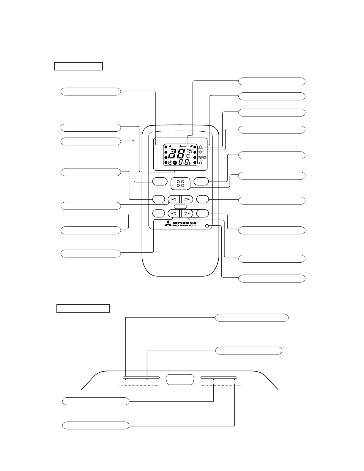
-
71
-
RUN HI POWER ECONOTIMER
Run (HOT KEEP) light (green)
TIMER light (yellow)
HI POWER light (green)
ECONOMY light (orange)
¡ Illuminates during operation.
Illuminates during TIMER operation.
Illuminates during HI POWER operation.
Illuminates during ECONOMY operation.
4 OUTLINE OF OPERATION CONTROL BY MICROCOMPUTER
(1) Operation control function by remote controller
CONT
HI POWER
ECONO
ON OFF
TIMER
FAN SPEED ON/OFF
MODE
TEMP
AIR FLOW
TIMER
CANCEL
HI POWER
ECONO ON OFF
ACL
AUTO
HI
MED
LO
Remote controller
FAN SPEED indicator
Indicators the ¡ for the fan speed which has
been set.
ON-TIMER • OFF-TIMER indicator
FAN SPEED button
Each time the button is pushed, the ¡
indicator is switched over in turn.
HI POWER button
This button changes the HI POWER
operation.
SET TEMPERATURE button
This button sets the room temperature.
ECONOMY button
This button changes the ECONOMY operation.
ON TIMER button
This button sets the ON timer times.
¡ Above figure shows all indications for the
purpose of explanation, but practically only
the pertinent parts are indicated.
Models All models
HI POWER operation indicator
Indicators during HI POWER operation.
ECONOMY operation indicator
Indicators during ECONOMY operation.
Operation switch over indicator
Indicators the ¡ for the operation which has
been set.
AIR FLOW indicator
Indicates selected flap mode.
OPERATION MODE select button
Each time the button is pushed, the ¡
indicator is switched over in turn.
ON/OFF button
This button, when pressed, starts operation
and stops when repressed.
AIR FLOW button
This button changes the flap mode.
CANCEL button
The button releases the TIMER operation.
OFF TIMER button
This button sets the OFF timer Times.
Reset switch
Switch for resetting microcomputer.
Indoor unit indicator
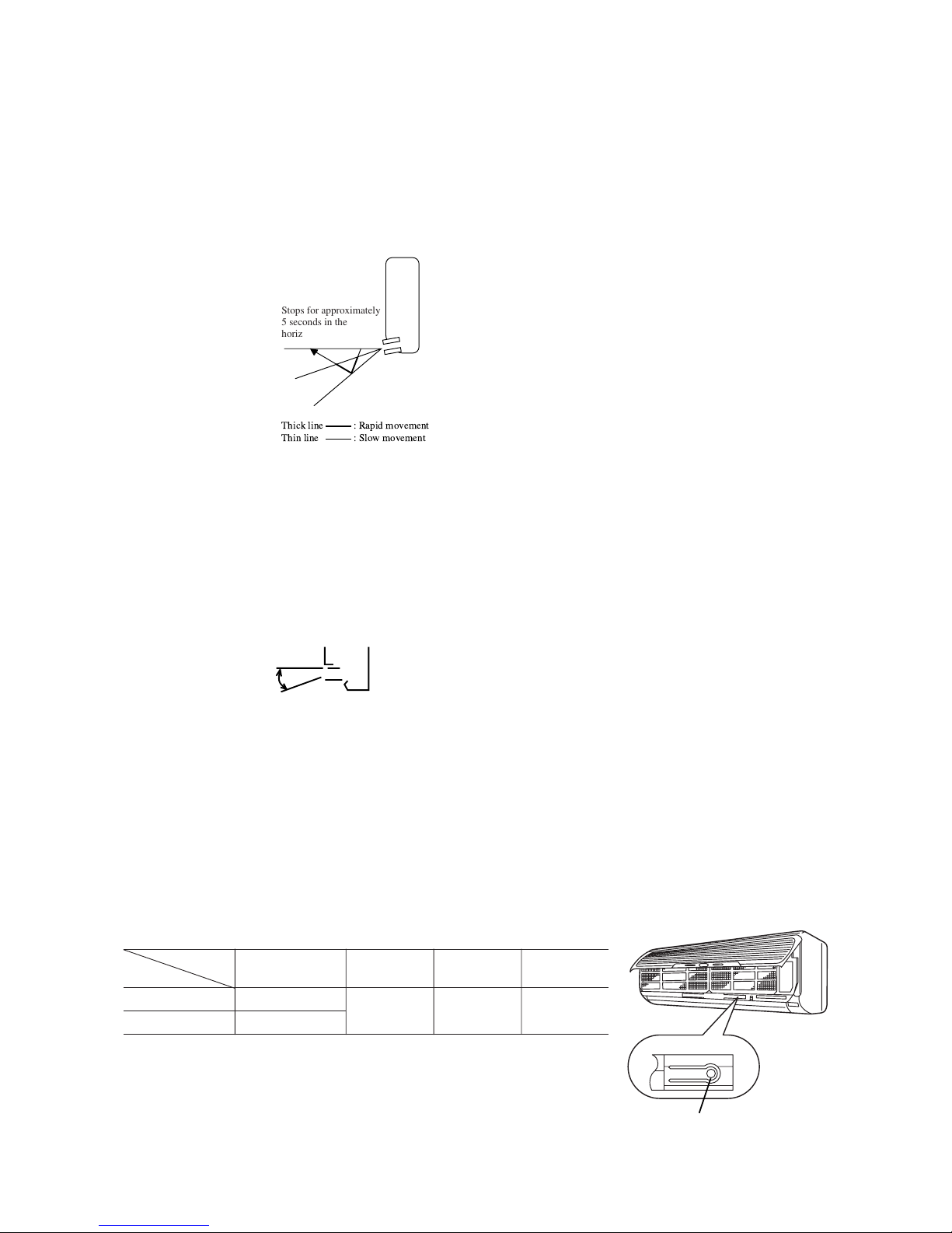
-
72
-
Stops for approximately
5 seconds in the
horizontal position.
(2) Flap control
Control the flap by AIRFLOW button on the wireless remote controller.
(a) Natural flow (AUTO)
The flap will be automatically set to the angle of air flow best to operation.
(i) Starting time of operation
s
In case of cooling
t
and dry operation
ON/OFF
Back-up switch
(c) Swing flap
Flap moves in upward and downward directions continuously.
(ii) When not operating
The flap returns to the position of air flow directly below, when operation has stopped.
(b) Memory flap
While the flap is operating if the AIRFLOW button is pushed once, it stops swinging at an angle.
As this angle is memorized in the microcomputer, the flap will be automatically set to the angle when next operation is
started.
¡ Recommendable stopping angle of the flap
On operating in automatic operation mode by back-up switch, functions show in the above
table are not altered, white, the other micro-computer control functions remain effective.
(3) Back-up Switch
When the remote controller batteries become weak, or if the remote controller is lost or malfunctioning, this switch may be used to
turn the unit on and off.
(a) Operation
Push the switch once to place the unit in the automatic mode. Push it once more to turn the unit off.
(b) Details of operation
The unit will go into the automatic mode in which it automatically determines, from room temperature (as detected by
thermistor), whether to go into the cooling or thermal dry modes.
Function
Room temperature
Operation mode
setting
Fan speed Flap Timer switch
Cooling About 26ºC
Thermal dry About 25ºC
Auto Natural flow Continuous
Horizontal
blowing
COOL•DRY

-
73
-
(4) AUTOMATIC operation
(a) Determination of operation mode
The blow operation of the indoor fan is carried out at the 1st speed for 20 seconds and the room temperature is checked to
determine the operation mode automatically. (When the unit is operated by the turn-on timer, the blow operation is not
carried out.)
(b) The temperature is checked once every 30 minutes after operation start. When the judgment is different from the previous
operation mode, the operation mode is transferred.
(c) When the unit is operated again within 30 minutes after the operation stop or the operation of the unit is changed to the
automatic operation during cooling, heating or dry operation, the unit is operated with the previous operation mode.
(d) Established temperature (operate by the established temperature button on remote controller).
(5) Comfort timer settings
Temperature is checked beginning 1 hour before the set time, and the power is turned on before the timer setting as necessary to
bring the temperature to the proper level by the set time.
Operation mode Room temperature thermistor (Th1)
Operating start time (amount of time
previous to set time that operation begins)
Over 40˚C 60 mins.
Cooling Over 35˚C 30 mins.
Over 30˚C 15 mins.
Notes (1) At 5 minutes before the set time of the turn-on timer, the operation is started regardless of the temperature of the room temperature thermister.
(2) When the dry or blow operation is selected, this function is not activated.
(However, when the automatic dry operation is selected, the function described in article (1) is operated.)
(6) Timer time setting
The turn-off timer and turn-on timer can be set for up to 12 hours in units of 1 hour.
(7) Night time turn off
Placing the timer to this setting changes the temperature setting of the indoor set button as follows:
Wireless remote control signal (Indication)
-6 -5 -4 -3 -2 -1 ±0+1+2+3+4+5+6
Cooling 20 21 22 23 24 25 26 27 28 29 30 31 32
Thermal dry 19 20 21 22 23 24 25 26 27 28 29 30 31
Temperature
setting
(8) Temperature adjustment
a) Temperature adjustment setting may be set between 18 and 30˚C.
b) The compressor and outdoor fan and turned on and off as shown below according to the temperature setting.
Cooling
c) During the continuous mode, the compressor runs continuously in cooling. For thermal dry, please refer to page 79.
Compressor
outdoor fan
Set temp.
Room temp.
Cooling, thermaldry
Start
Timer operation
(time)
Temperature
setting (˚C)
21ºC Room temperature<26ºC 26ºC Room temperature
Operation mode Dry Cooling

-
74
-
(b) Fan speed knob: AUTO
The indoor fan is automatically controlled in accordance with the difference between the room temperature (detected by the
room temperature thermistor) and the thermostat setting as shown below.
Mode
Cooling Fan
18~30˚C
Thermostat setting point Thermostat setting point
Continuous Speed 5 Speed 4
(9) Fan control
(a) Fan speed change
Note (1) Thermostat operation is performed in A, B Block. When compressor and indoor fan stop by thermostat operation within 12 minutes from start, temperature
check is performed by operating indoor fan at speed 1 for 20 seconds before finishing 12 minutes and allowing decision of next operation block.
D Block C Block B Block A Block
(10) DRY operation
(a) Choose the appropriate operation block area by the difference between room temperature and thermo-
stat setting temperature as shown below.
¡Operation block area
–2 0 +3
Room temp. – Setting temp.(deg)
(b) Start up operation
ON
OFF
OFF
0
3
6
912
ON
OFF
OFF
0
12
Compressor
and
outdoor fan
Set fan speed
Indoor fan
Start
Temperature check
Start
Temperature check
Compressor
and
outdoor fan
Set fan speed
Indoor fan
Operation block decision
C.D Block
A.B Block
minutes
minutes
Speed 1
20
seconds
Mode
COOL FAN
Fan speed knob
AUTO See below
LOW Speed 2 Speed 2
MED Speed 3 Speed 3
HIGH Speed 4 Speed 4
Note (1) Please refer to page 74 regarding dry operation.
Note (1) Please refer to page 74 regarding dry operation.
Setting temp
Speed 1
Speed 3
Speed 4
Speed 2
Speed 2
Speed 3
Speed 1
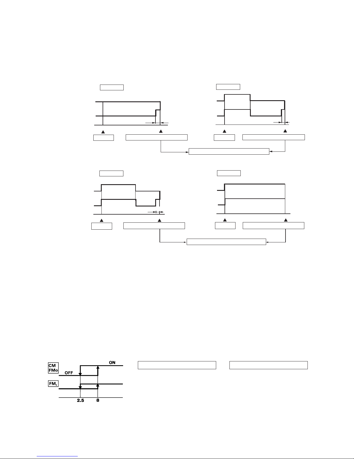
-
75
-
ON
OFF
OFF
0
4
8
ON
OFF
OFF
0
8
OFF
OFF
0
8
ON
OFF
OFF
0
3
8
(c) DRY operation
After finishing start up operation described in (b) above, thermal dry operation is performed at 8 minutes intervals, according
to the difference between room temperature and thermostat setting temperature as shown below.
Beside, 1 cycle of this operating time consists of 8 minutes, 7 cycle operation is performed then.
Compressor
and
outdoor fan
Indoor fan
D Block
Compressor
and
outdoor fan
Indoor fan
C Block
Compressor
and
outdoor fan
Indoor fan
B Block
Compressor
and
outdoor fan
Indoor fan
A Block
20 seconds
20 seconds
minutes
minutes
Start
Temperature check
Start
Temperature check
Operation block decision
20 seconds
minutes
minutes
Start
Temperature check Temperature check
Operation block decision
Start
Speed 1
Speed 1
Speed 1
Speed 1
(11) Dew condensation prevention control for cooling operation
This prevents dew condensation, in the indoor unit, from occurring.
(a) Operating condition: when 52C is kept ON for 30 min. after the unit starts operation.
(b) Operation content: forces the indoor fan to change from Speed 1 to Speed 2.
(c) Resetting condition: When 52C is off, or when dew condensation prevention control has been operating continuously for
30 minutes.
(12) Frost prevention for indoor heat exchanger [Preventing frost accumulation on the indoor heat exchanger]
During the Cooling or Dry operation in low room air temp. condition, evaporating temperature will decrease and consequently
indoor heat exchanger sometimes gets clogged with frost (or ice).
In order to prevent this trouble, compressor is stopped by under mentioned condition by indoor heat exchanger sensor (Th
2) and
timer (built into micro computer circuit) functions.
Also indoor fan is changed over to speed 1.
CM, FMO stoppage condition
1 Temperature of heat exchanger is
2.5˚C or lower.
2 As least 10 minutes has passed
since the compressor started.
Indoor heat exchanger
temperature (˚C)
CM, FMO re-starting condition
1 Temperature of heat exchanger is
8˚C or higher.
2 As least 3 minutes has passed since
the compressor stopped.
Set fan
speed
speed 1
-
76
-
(16) Self diagnosis function
When something abnormal happens on the outdoor unit, indoor unit fan motor and each sensor (heat exchanger, room tempera-
ture,) it will be indicated by flashing lamps.
(a) Abnormality of outdoor unit:
1) Cooling operation
When the indoor heat exchanger temperature does not fall to 25˚C or below for 40 minutes after 5 minutes have elapsed since
the compressor operation start, the abnormality stop occurs. (The timer lamp flashes 5 times.)
(b) Abnormality of indoor fan motor:
When the status that the fan motor speed is 300 rpm or under continues for 30 seconds or more during the indoor fan motor
operation, the unit is stopped. The fan motor operation is restarted after 10 seconds, however, if the fan is stopped again, the
air-conditioner is completely stopped as the indoor fan motor abnormality and the abnormality indication is displayed. (The
operation lamp flashes 6 times.)
(c) Abnormality of heat exchanger thermistor:
RUN lamp will flashing when the input temperature of the heat exchanger thermistor measures less than –20˚C for more than
3 seconds with the air-conditioner “OFF”. (will not flashing during operation)
(d) Abnormality room temperature thermistor:
RUN lamp will flashing when the input temperature of the room temperature thermistor measures less than –20˚C for more
than 3 seconds with the air-conditioner “OFF”. (will not flashing during operation)
Note (1) If the above abnormalities happen concurrently, the lamp will flashing in the order of item number (a) through (d) above.
(15) Economy operation (Remote controller “ECONO” button on)
(a) Cooling economy operation
The set temperature is raised by 2˚C and the unit is operated in cooling mode.
(b) Thermal dry economy operation
Thermal dry operation carried out at 2˚C higher than the set temperature.
(c) Blow economy operation
The indoor fan is controlled as follows.
(13) Three-minute forced operation
When the compressor begins operating the thermal operation is not effective for 3 minutes, so operation continues as is in the
operation mode. (After 3 minutes has passed the thermal operation is effective.)
However, stopping the compressor via a stop signal or protection control has priority.
(14) High power operation (Remote controller “HI POWER” button on)
The indoor unit fan rotates at speed 6 for 15 minutes, and carries out continuous cooling and Fan.
Set temperature +1 +2
OFF
1st speed
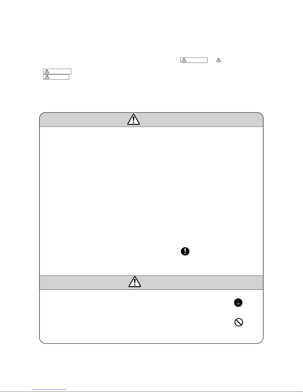
-
77
-
5 APPLICATION DATA
SAFETY PRECAUTIONS
¡ Please read these “Safety Precautions” first then accurately execute the installation work.
¡
Though the precautionary points indicated herein are divided under two headings, WARNING and CAUTION , those points
which are related to the strong possibility of an installation done in error resulting in death or serious injury are listed in the
WARNING section. However, there is also a possibility of serious consequences in relationship to the points listed in the
CAUTION section as well. In either case, important safety related information is indicated, so by all means, properly observe all
that is mentioned.
¡ After completing the installation, along with confirming that no abnormalities were seen from the operation tests, please explain
operating methods as well as maintenance methods to the user (customer) of this equipment, based on the owner’s manual.
Moreover, ask the customer to keep this sheet together with the owner’s manual.
WARNING
¡ This system should be applied to places as households, residences and the like. Application to inferior environ-
ment such as engineering shop could cause equipment malfunction.
¡ Please entrust installation to either the company which sold you the equipment or to a professional contractor.
Defects from improper installations can be the cause of water leakage, electric shocks and fires.
¡ Execute the installation accurately, based on following the installation manual. Again, improper installations can
result in water leakage, electric shocks and fires.
¡ For installation, confirm that the installation site can sufficiently support heavy weight. When strength is insuffi-
cient, injury can result from a falling of the unit.
¡ For electrical work, please see that a licensed electrician executes the work while following the safety standards
related to electrical equipment, and local regulations as well as the installation instructions, and that only exclusive use circuits are used.
Insufficient power source circuit capacity and defective installment execution can be the cause of electric shocks
and fires.
¡ Accurately connect wiring using the proper cable, and insure that the external force of the cable is not conducted
to the terminal connection part, through properly securing it improper connection or securing can result in heat
generation or fire.
¡ Ta ke care that wiring does not rise upward, and accurately install the lid/service panel. It’s improper installation
can also result in heat generation or fire.
¡ When setting up or moving the location of the air conditioner, do not mix air etc. or anything other than the
designated refrigerant (R22) within the refrigeration cycle.
Rupture and injury caused by abnormal high pressure can result from such mixing.
¡ Always use accessory parts and authorized parts for installation construction. Using parts not authorized by this
company can result in water leakage, electric shock, fire and refrigerant leakage.
¡ Ventilate the work area when refrigerant leaks during the operation.
Coming in contact with fire, refrigerant could generate toxic gas.
¡ Confirm after the foundation construction work that refrigerant does not leak.
If coming in contact with fire of a fan heater, a stove or movable cooking stove, etc., refrigerant leaking in the
room could generate toxic gas.
CAUTION
¡ Execute proper grounding. Do not connect the ground wire to a gas pipe, water pipe, lightning rod or a telephone
ground wire.
Improper placement of ground wires can result in electric shock.
¡ The installation of an earth leakage breaker is necessary depending on the established location of the unit.
No installing an earth leakage breaker may result in electric shock.
¡ Do not install the unit where there is a concern about leakage of combustible gas.
The rare event of leaked gas collecting around the unit could result in an outbreak of fire.
¡ For the drain pipe, follow the installation manual to insure that it allows proper drainage and thermally insulate it
to prevent condensation. Inadequate plumbing can result in water leakage and water damage to interior items.

-
78
-
5.1 Selection of location for installation
(1) Indoor unit
(a) Where there is no obstructions to the air flow and where the
cooled air can be evenly distributed.
(b) A solid place where the unit or the wall will not vibrate.
(c) A place where there will be enough space for servicing. (Where
space mentioned below can be secured)
(d) Where wiring and the piping work will be easy to conduct.
(e) The place where receiving part is not exposed to the direct rays of the sun or the strong rays of the street lighting.
(2) Outdoor unit
(a) A place where good air circulation can be obtained.
(b) A place where the exhausted air will not be sucked in for the
second time.
(c) A place where the unit will not be affected by other heat sources.
(When there are several units installed or another heat source)
(d) Do not install the unit near the seaside, or where there is possibil-
ity of chlorine gas generation.
(e) A place where discharged hot air or unit’s operating sound will
not be nuisance to the neighbourhood.
(f) A place where servicing space can be secured.
(g) A place where vibration will not be enlarge.
150
100
65
50
Left
side
Right
side
Unit : mm
Ver tical height
difference (H)
Model
Item
All models
One way piping length (R) 15
Outdoor
unit is lower
5 m
Outdoor unit
is higher
5 m
(3) Limitations for one way piping length and vertical height difference.
R
h
100
600
800
Air inlet
Service
space
()
Air inlet
Air
Outlet
Note (1) If the wall is higher than 1.2 m or a ceiling is
present, distances larger than indicated in the
above table must be provided.
Unit : mm

-
79
-
5.2 Installation of indoor unit
(1) Installation if installation board
(a) Fixing of installation board
Lock for the inside wall structures (Intermediate support or pillar)
and firmly install the unit after level surface has been checked.
Adjustment of the installation
board in the horizontal direction
is to be conducted with lour screws
in a temporary tightened state.
Adjust so that board will be level
by turning the board with the
standard hole as the center.
Fixing on concrete wall
Use of nut anchor Use of bolt anchor
Standard hole
Bolt
(M6 × 12)
Mounting
board
Nut
(M6)
Mounting
board
Max. 10
Mating Mark for Lever Surface
(Horizontally)
(b) Fixing method of installation board
(2) Drilling the and installation of sleeve
(a) Drill a hole with ø65 whole core drill
Note (1) Drill a hall with incline of 5 degree from
indoor side to outdoor side.
Indoor side Outdoor side
(b) Adjusting sleeve lenght (Option parts)
Cut off the sleeve
collar in case of
drawing piping out
to rear.
Cut off the sleeve
cooler that can be
seen from beneath
the unit.
Wall thickness
+ 1.5 cm
(c) Install the sleeve
(Inserting sleeve) (*Sleeve + *Inclined + *Sealing plate)
Indoor side Outdoor side
Turn to
tighten
Paste
View of sleeve when installed
Inclined
flange
Sealing
plate
Sleeve
Indoor side Outdoor side
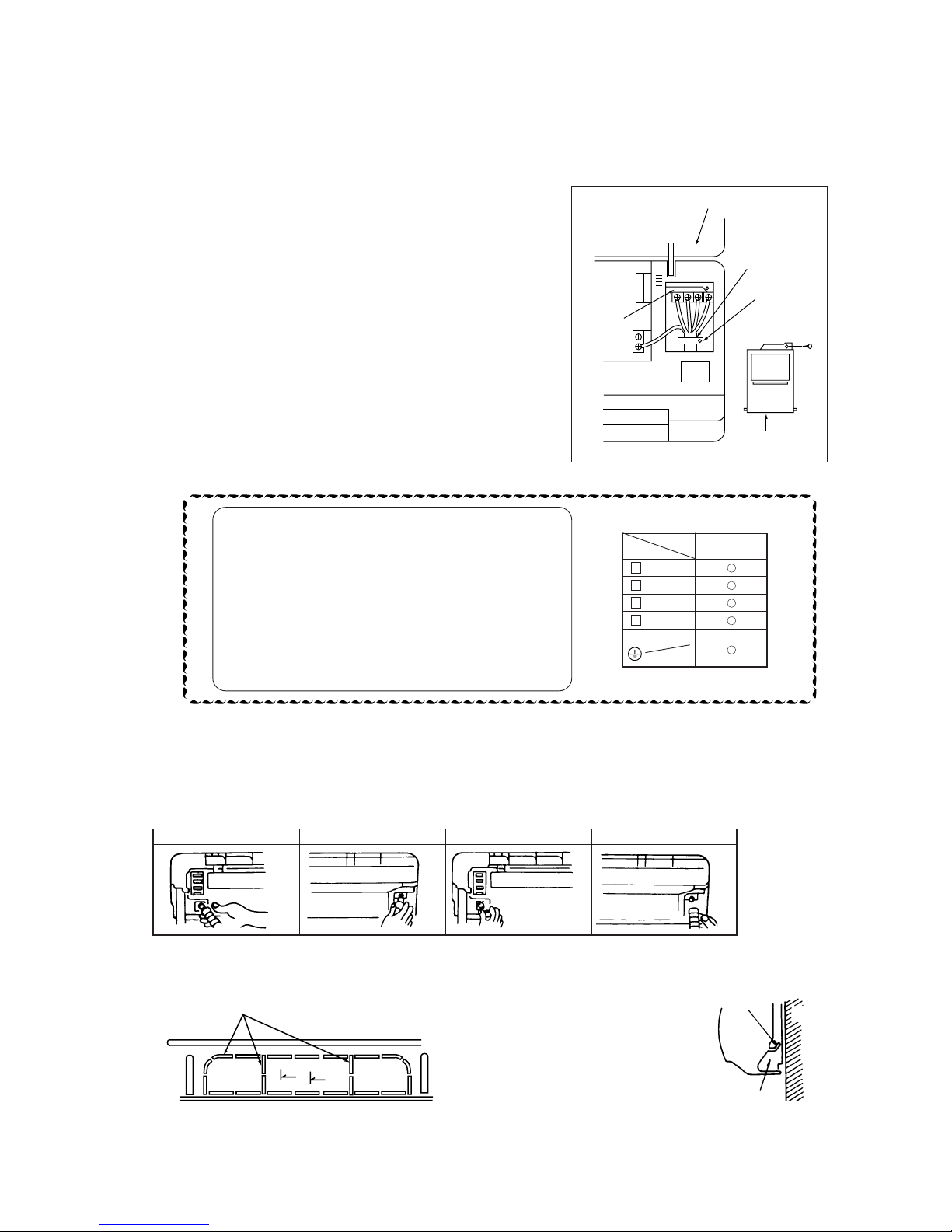
-
80
-
(3) Preparation of indoor unit
(a) Mounting of connecting wires
(i) Open the suction grille, then remove the lid.
(ii) Remove the wiring clamp.
(iii) Pass the connecting wire to terminal block from behind of indoor
unit.
(iv) Connect the connecting wire securely to the terminal block.
1 Connect the connection wire securely to the terminal block. If the
wire is not affixed completely, contact will be poor, and it is dan-
gerous as the terminal block may heat up and catch fire.
2 Ta ke care not to confuse the terminal numbers for indoor and out-
door connections.
3 Affix the connection wire using the wiring clamp.
(v) Fix the connecting wire by wiring clamp.
(vi) Attach the lid.
(vii) Close the suction grille.
(b) Protective taping (Protect the cable with tape at the section where the cable passes through the hole opened on the wall.)
(c) Forming of pipe (Holding down the pipe at the root, change the pipe direction, extend it and adjust according to the
circumstance.)
Screw
Suction grille
Connecting wire
Wiring clamp
Terminal
block
Lid
[When the pipe is extended to left and taken out from the rear center]
Note (1) It is designed to collect moisture
accumulated on the rear face in the
drain pan. Be sure not to accommodate
the power cable, etc. above the chute.
¡ When arranging the pipe through a hole opened at the center, open the
knockout hole using nippers, etc.
(Drain pipe relocation procedure)
1. Remove the drain pipe. 2. Remove the drain cap. 3. Insert the drain cap. 4. Connect the drain pipe.
¡ Loosen the spring clamp and
securely insert the drain pipe.
Note: If it is inserted insufficiently,
water leakage could result.
Pipe accommodation space
¡ Loosen the spring clamp to
remove.
¡ Remove by hand or use
cutting pliers, etc.
¡ Securely insert the drain cap
removed in the step 2.
Note: If it is inserted insufficiently,
water leakage could result.
Chute
Wall
Cooling only
type type
1 BROWN
2 BLUE
3 BLACK
4 GREEN
YELLOW
GREEN
Use cables for interconnection wiring to avoid loosening of the wires.
CENELEC code for cables Required field cables.
H05 RNR3G1.5 (Example)
H Harmonized cable type
05 300/500 volts
R Natural-and/or synth, rubber wire insulation
N Polychloroprene rubber conductors insulation
R Stranded core
3or5 Number of conductors
G One conductor of the cable is the earth conductor
(yellow/green)
1.5 Section of copper wire (mm2)

-
81
-
(4) Installation of indoor unit
(a) Hang the upper portion of the unit rear cover on the mounting board,
and then magnet on the lower unit portion will pull to fix the unit.
(b) Be sure not to leave any trap on the drain pipe.
Wall
Declining slope
Inverted slipe
Trap
Slighty push
Mounting
block
5.3 Installation of outdoor unit
(1) Installation of outdoor unit
(a) Make sure that sufficient space for installation and service is secured.
(b) Fix the leg sections of the unit on a firm base which will not play.
Attach cushion pads, etc. between the unit and the mounting fixtures not to transmit vibration to the building.
(c) Attach a drain elbow, etc. under the drain port of the bottom plate to guide drain water. (Drain elbow should not be used
where days when temperature drops below 0˚C continue for several days. Draining may be disturbed by frozen water.)
(d) When installing the unit at a higher place or where it could be toppled with strong winds, secure the unit firmly with founda-
tion bolts, wire, etc.
(2) Connection of indoor and outdoor connecting wiring
(a) Connect the wiring according to the number of the indoor terminal block. (Mis-wiring may cause the burning damage, and
make sure to connect correctly.)
(b) When an abnormality is indicated on the outdoor unit for the cooling only model, check the fuse on the outdoor unit. If the
fuse is burnt out, replace it with new one.
5.4 Refrigerant piping
(1) Preparation
Keep the openings of the pipes covered with tapes etc. to prevent dust, sand, etc. from entering them.
Indoor unit side
Outdoor unit side
¡ Remove the flared nuts.
(on both liquid and gas sides)
¡ Remove the flared nuts.
(on both liquid and gas sides)
¡ Install the removed flared nuts to the pipes to be connected,
then flare the pipes.
Dimension A
Liquid side
(φ6.35): 9-9.5 dia
Gas side
(φ12.7): 16.2-17 dia
Press
Remove
Press
Remove
(Do not
turn)
Cooling only
type type
1 BROWN
2 BLUE
3 BLACK
4 GREEN
YELLOW
GREEN

-
82
-
(2) Connection of refrigerant piping
Indoor unit side
¡ Connect firmly gas and liquid side
pipings by Torque wrench.
¡ Specified torquing value:
Liquid side (ø6.35) : 15.7~19.6 N·m(1.6~2.0 kgf·m)
Gas side (ø12.7) : 39.2~49.0 N·m(4.0~5.0 kgf·m)
Outdoor unit side
¡ Connect firmly gas and liquid side
pipings by Torque wrench.
¡ Specified torquing value:
Liquid side (ø6.35): 15.7~19.6 N·m(1.6~2.0 kgf·m)
Gas side (ø12.7) : 39.2~49.0 N·m(4.0~5.0 kgf·m)
¡ Use one more spanner to fix the valve.
Spanner
(for fixing
the piping)
Tor que
wrench
¡ Always use a Torque wrench and back up spanner to tighten the flare nut.
(3) Air purge
(a) Tighten all flare nuts in the pipings both indoor and outside wall so as not to cause leak.
(b) Connect operating valve, charge hose, manifold valve and vacuum pump as is illustrated below.
(c) Open manifold valve handle Lo to its full width, and perform vacuum or evacuation.
Continue the vacuum or evacuation operation for 15 minutes or more and check to see that the vacuum gauge reads
– 0.1MPa (– 76cm Hg).
(d) After completing vacuum operation, fully open operating valve (Both gas and liquid sides) with hexagon headed wrench.
(e) Check for possible leakage of gas in the connection parts of both indoor and outdoor.
(4) Insulation of connecting portion
1) Cover the connection portion of the refrigerant piping with
the pipe cover and seal them.
If neglecting to do so, moisture occurs on the piping and
water will drip out.
2) Finishing and fixing
a) Tie up the piping with wrapping tape, and shape it so
that it conforms to which the pipe is attached.
b) Fix them with clamps as right figure.
Stop valve
(Two-way valve)
Service port
Charge hose
Vacuum pump
Charge hose
Handle Hi
(pressure)
Manifold
valve
Pressure
gauge
Compound
(Gauge)
Stop valve
(Three-way
valve)
Handle Lo
(pressure)
–76 cm Hg
Vinyl tape
To cover the connecting portion with
insulation materials, cut upper portion and
then seal it with insulation materials.
Cover the exterior portion with
covering tape and shape the piping
so it will match the contours of the
route that the piping to take. Also
fix the wiring and pipings to the
wall with clamps.
Insulation
Refrigerant piping
Electrical wiring
Covering tape
Drain hose
Tapping screw
Additional refrigerant charge
When refrigerant piping exceeds 7m conduct additional refrigerant charge after refrigerant sweeping.
A mount of additional charge per meter : 20g/m
Example of additional charge amount calculation
Calculate the additional charge amount, when the piping length is 10m.
(10 – 7)m × 20g/m = 60g 60g for additional charge amount
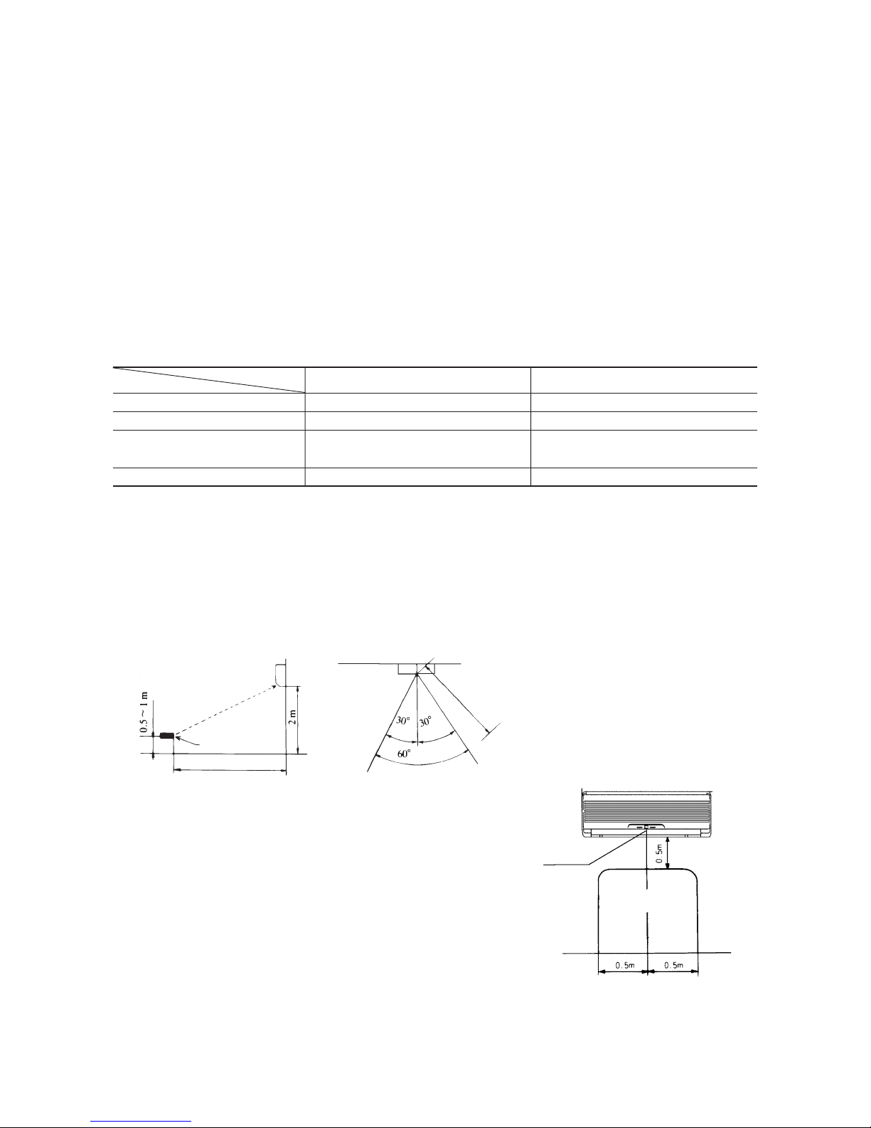
-
83
-
5.5 Test run
(1) Conduct trial run after confirming that there is no gas leaks.
(2) When conducting trial run set the remote controller thermostat to continuous operation position. However when the power source
is cut off or when the unit’s operation switch is turned off or was turned to fan operation position, the unit will not go into operation
in order to protect the compressor.
(3) Insert in electric plug into the electric outlet and make sure that it is not loose.
(a) When there is something wrong with the electric outlet and if the insertion of the electric plug is insufficient, there may occur
a burn out.
(b) It is very important to be careful of above when pulgging in the unit to an already furnished electrical outlet.
(4) Explain to the customer on the correct usage of the air conditioner in simple layman’s terms.
(5) Make sure that drain flows properly.
(6) Standard operation data
Note (1) The data are measured at following conditions.
Ambient air temperature
Indoor side: Cooling ... 27°C DB, 19°C WB
Outdoor side: Cooling ... 35°C DB, 24°C WB
(230V)
Item
Model
SRK50CA SRK56CA, 56CA-4
High pressure MPa(kgf/cm2)– –
Low pressure MPa(kgf/cm2) 0.39~0.49 (4~5) 0.34~0.44 (3.5~4.5)
12~16 12~16
Running current (A) 8.4/8.0/7.7 9.7/9.3/8.9
Temp. difference between
suction air and discharge air (˚C)
5.6 Precautions for wireless remote controller installation and operation
(1) Wireless remote controller covers the following distances:
(a) When operating facing the air-conditioner:
Notes (1) The remote controller is correctly facing the sensing
element of the air conditioner when being manipulated.
(2) The typical coverage is indicated (in the left illustration).
It may be more or less depending on the installation.
(3) The coverage may be less or even nil. If the sensing
element is exposed to strong light, such as direct
sunlight, illumination, etc., or dust is deposited on it or
it is used behind a curtain, etc.
less
or
or less
5 m or less
Wireless remote
controller
5 m or less
Remote control
available in this area.
Receiver
or less
(b) When manipulating the remote controller mounted on a wall:
Make sure that it works normally (i.e., transmission/reception signal is
audible) before mounting.

-
84
-
6 MAINTENANCE DATA
6.1 Trouble shooting
(1) Trouble shooting to be performed prior to exchanging PCB, (Printed circuit board) [Common to all models]
All the models described in this chapter are controlled by a microcomputer. When providing maintenance service to customers it
is necessary to understand the function controlled by a micro computer thoroughly, so as not to mistakenly identify correct opera-
tions as mis-operations. It is also necessary to perform the following simple checks before conducting detailed checks or exchang-
ing printed circuit board.
Before exchanging Printed circuit board
Claim call from the user
Ascertain the nature of the claim.
Ascertain the operation status.
Does the trouble occur again?
Is this nonsense claim?
Operate the unit.
Does the trouble occur again?
Temporarily turn off the power source and
turn it on again in about 1 min. and turn the
unit on again.
YES
No
YES
YES
Does the trouble occur again?
Disconnect connectors and connect them
again.
Operate the unit again after confirming that the fuse
and the varistor equipped on PCB does not burn out.
Carry out checks according to detailed
check process (See later page)
Unit did not cool, etc.
¡ Is the power on?
¡ Is the thermostat setting correct?
(Not too high?)
¡ Is the unit in a timer operation?
¡ Does user understand function?
etc.
¡ Explain the function of the unit to user.
No need for PCB change
Check further the status when the trouble occured
(such as the timer of occurence, power failures, thunder, use status of other electrical appliances, etc).
Clarify the reason for the problem and explain it thoroughly to the user.
No need for PCB change
Microcomputer runaway due to power source
conditions is a possible cause.
No need for PCB change
The cause is defective connector contact.
YES
No
No
No
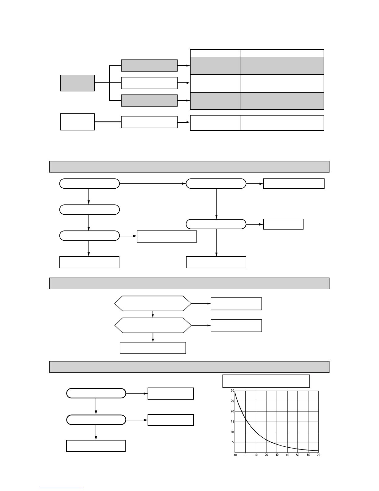
-
85
-
(2) Indication of Self Diagnosis (Indoor unit)
Anormality of thermistor Disconnection of thermistor and defective connection of connector
(Disconnection)
(Short circuit)
Resistance value
(kΩ)
Temperature (°C)
Is connection to connector
good?
Is thermistor resistance
value normal?
Replace PCB.
Repair connector.
Replace thermistor.
No
No
Ye s
Ye s
Chart for thermistor temperature
resistance characteristics
No
No
Ye s
Ye s
Ye s
Ye s
Ye s
No
No
Replace protective device.
Replace capacitor.
Is capacitor normal?
Insufficient gas.
Replace compressor.
Is protective device normal?
Does compressor operate?
Clogging of capillary tube. etc.
Is abnormality the same after
gas charging?
Is refrigerant circulation
volume normal?
No
No
Ye s
Ye s
The fan motor is defective.
Repair the connector.
Is voltage being applied to the
fan motor?
The indoor circuit board
is defective.
Is the connector connection
good?
Note (1) When an abnormality is indicated on the outdoor unit for the cooling only model, check the fuse on the outdoor unit. If the fuse is burnt out, replace it
with new one.
TIMER lamp
is lights
continuously.
RUN lamp is flashing.
(1 Time flash.)
RUN lamp is flashing.
(2 Time flash.)
RUN lamp is flashing.
(6 Time flash.)
TIMER lamp is flashing.
(5 Time flash.)
Connect of Defect
Abnormality of heat
exchanger thermistor.
Abnormality of room
temperature thermistor.
Abnormality of indoor
fan motor.
Abnormality of outdoor
unit.
Place of defect
¡ Disconnection of heat exchanger thermistor.
¡ Disconnection of room temperature
thermistor.
¡ Fan motor is defective.
¡ Printed circuit board is defective.
¡ Compressor is defective.
¡ Capacitor is defective.
¡ Gas is short.
RUN lamp is
lights
continuously.
(3) Troubleshooting
Abnormality of outdoor unit [Compressor malfunction of insufficient gas (refrigerant)]
Abnormality of indoor fan motor (Fan motor defective, printed circuit board defective)
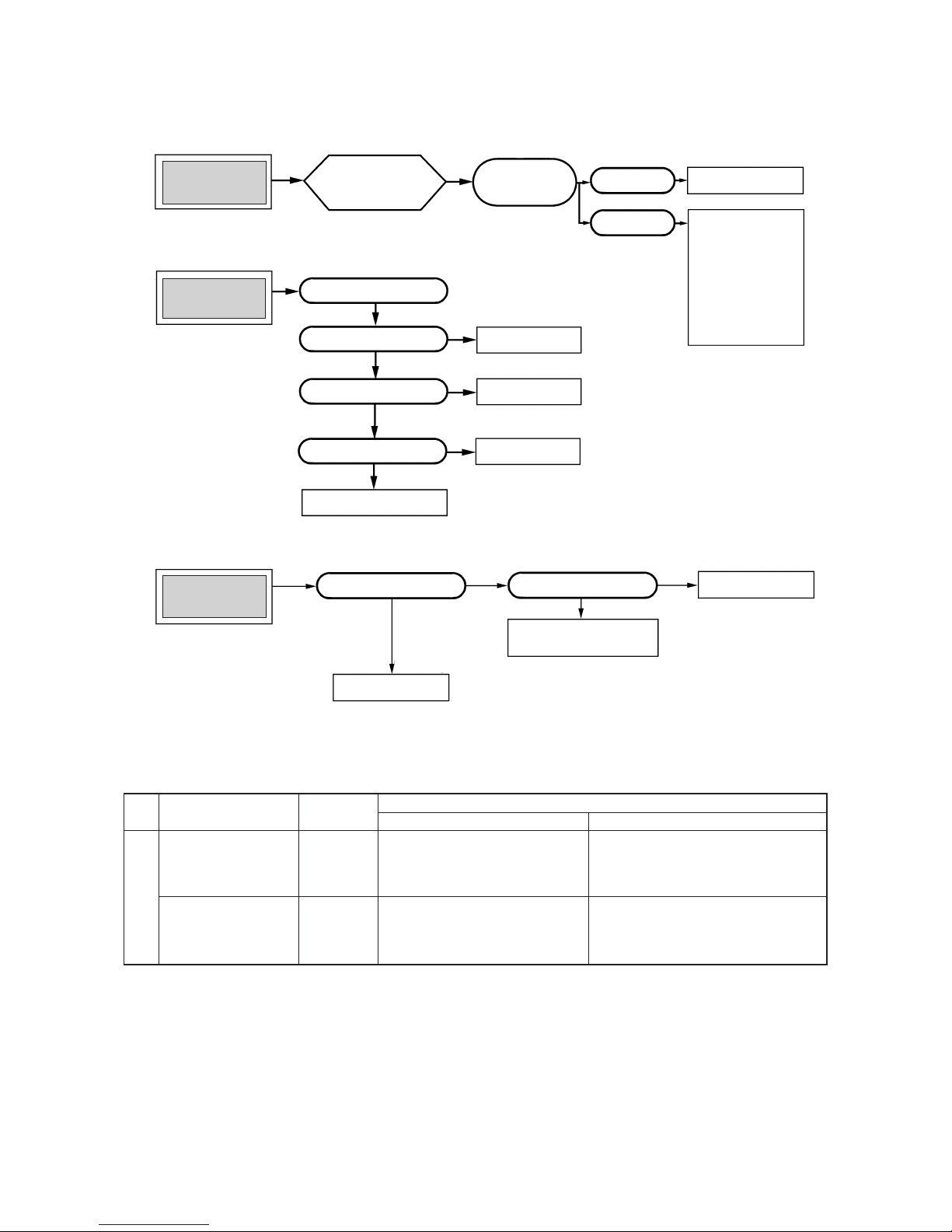
-
86
-
(4) Trouble Diagnostic Procedures
Unit malfunctions or
does not stop.
Replace PCB.
Microcomputer rarely
mis-starts even during
times or power supply
or power failure, but, it
can sometimes occur
during those times. If it
occurs, check the operation, when the result is
positive then proceed as
normal.
Runaway of micro-
computer
Remove receptacle.
Insert it after 3 min.
and operate.
No change.
Normal operation.
Indoor lamp of
indoor unit does not
illuminate.
Check receptacle voltage.
Check if PCB fuse is blown.
Check varistor.
Check transformer secondary
voltage
Replace PCB.
Replace fuse.
Replace varistor.
Replace transformer
No
No
Outdoor fan does not
operate.
Check voltage with fan
connector.
Replace PCB.
Check capacitor.
Replace fan motor.
Replace capacitor.
Abnormal
Ye s
Normal
Unit Thermistor Operation
Function
Short circuit Broken connection
Cooling
Cooling
Indoor unit
Room temperature
thermistor
(1)
(Th1) except
for “continuous” thermal
setting.
Cooling will not operate
¡ FM
I : continuous operation
¡ CM,FM
o: stopped
Cooling will operate
¡ Heat exchanger frost preventer begins to operate
¡ Cools alternately for 10 minutes, stopping for 3
minutes.
(5) Trouble shooting chart for the room temperature thermistor (Th1), heat exchanger thermistor (Th2)
Continuous Cooling operation
¡ Cannot be turned ON/OFF by thermostat
¡ When FMI is on. “AUTO” is continuously
Hi
Heat exchanger
thermistor (Th
2)
Cooling will not operate.
Note (1) When the room temperature thermistor (Th
1) will not operate normally. Cooling operation may be run continuously by putting the thermostat setting on
“CONTINUOUS”

-
87
-
6.2 Servicing
(1) Evacuation
The evacuation is an procedure to purge impurities ...... noncondensable gas, air, moisture from the refrigerant equipment by using
a vacuum pump. Since the refrigerant R22 is very insoluble in water, even a small amount of moisture left in the refrigerant
equipment will freeze, causing what is called water clogging.
¡ Evacuation procedure
(a) Check to ensure that there is no internal pressure in the unit. If there is an internal pressure, it
should be relieved through the check joint.
(b) Connect the service hoses of the gauge manifold to the check joint of the gas & liquid piping.
(c) Connect a vacuum pump to the charge hose A . Repeat evacuation in the following sequence.
(6) How to make sure of remote controller
(1)
Is remote
controller
normal?
YES
Again pushing
operating switch
Operating the
unit?
NO
Does operating
backup switch
YES
Replace the
display
Remote controller
defects
Abnormal is not
fount
It is normal
Remote
controller defects
NO
NO
YES
NO
CONT HIPOWER ECONO
Note (1) How to check the remote controller
(a) Press the reset switch of remote controller.
(b) If the almost normal if entire display of remote control-
ler is shown after
indication.
Liquid side
Gas side
Check joint
Service hose
Charge hose
Vacuum
pump
Refrigerant
cylinder
Gauge
manifold
Stop the vacuum pump.
Notes (1) Do not use the refrigerant pressure to expel air.
(2) Do not use the compressor for evacuation.
(3) Do not operate the compressor in the vacuum condition.
Start the vacuum pump
Operate the vacuum pump for more than 15 minutes after –0.1MPa
(–76 cmHg) is indicated.
Close low pressure valve 1 of gauge manifold.
Operating the unit?
Control unit defects
YES
Operating the
unit by remote
controller?

-
88
-
(2) Modification method
Cut the jumper wire for the “REMOTE” section on the printed circuit board.
Carefully position the jumper wire so that it does not come in contact with other parts.
6.3 Power supply remote operation
When the remote part on indoor unit PCB is modified, the air conditioner is turned ON-OFF by power supply ON-OFF operation
without using remote control switch.
After the power supply remote operation, the operation contents can be modified by the remote controller.
(1) Operation contents
Power supply ON
3-minute timer
operation
Power supply OFF
Air conditioner
STOP
Start operation
AUTO
COOL: 26˚C
DRY: 25˚C
AUTO
AUTO
Continuous
Operation change
Set temperature
Air capacity change
Flap
Timer
(2) Refrigerant charge
(a) Discharge refrigerant entirely from the unit and evacuate the unit.
Note: Addition of refrigerant without evacuation is unreasonable, because it will result in low charge or overcharge.
(b) Keep the gauge manifold and connect a refrigerant cylinder to the unit.
(c) Record the weight of the refrigerant cylinder on the balance. This is necessary for making sure of the charged refrigerant
amount.
(d) Purge air from the charge hose A .
Firstly loose the connecting portion of the charge hose A at the gauge manihold side and open the valve 3 for a few seconds,
and then immediately retighten it after observing that gas is blow out from the loosened portion.
(e) Open the valve 1 and 3 after discharging air from the charge hose A , then the gas refrigerant begins flowing from the
cylinder into the unit. Be sure to erect the refrigerant cylinder upright to let gas refrigerant flow into the unit.
(f) When refrigerant has been charged into the system to some extent, refrigerant flow becomes stagnant, when that happens,
start the compressor in cooling cycle until the unit is filled with gas to the specified weight.
(g) Making sure of the refrigerant amount, close the valve 3.
(h) Disconnect the charge hose from the unit. Cover the valve ports of the refrigerant piping with caps and tighten them securely.
(i) Check for gas leakage applying a gas leak detector along the piping line.
(j) Start the air conditioner and make sure of its operating condition ...... high side and low side pressures and temperature
difference between suction air and outlet air.
REMOTE
CNE
CNG
CNH
CUSTOM

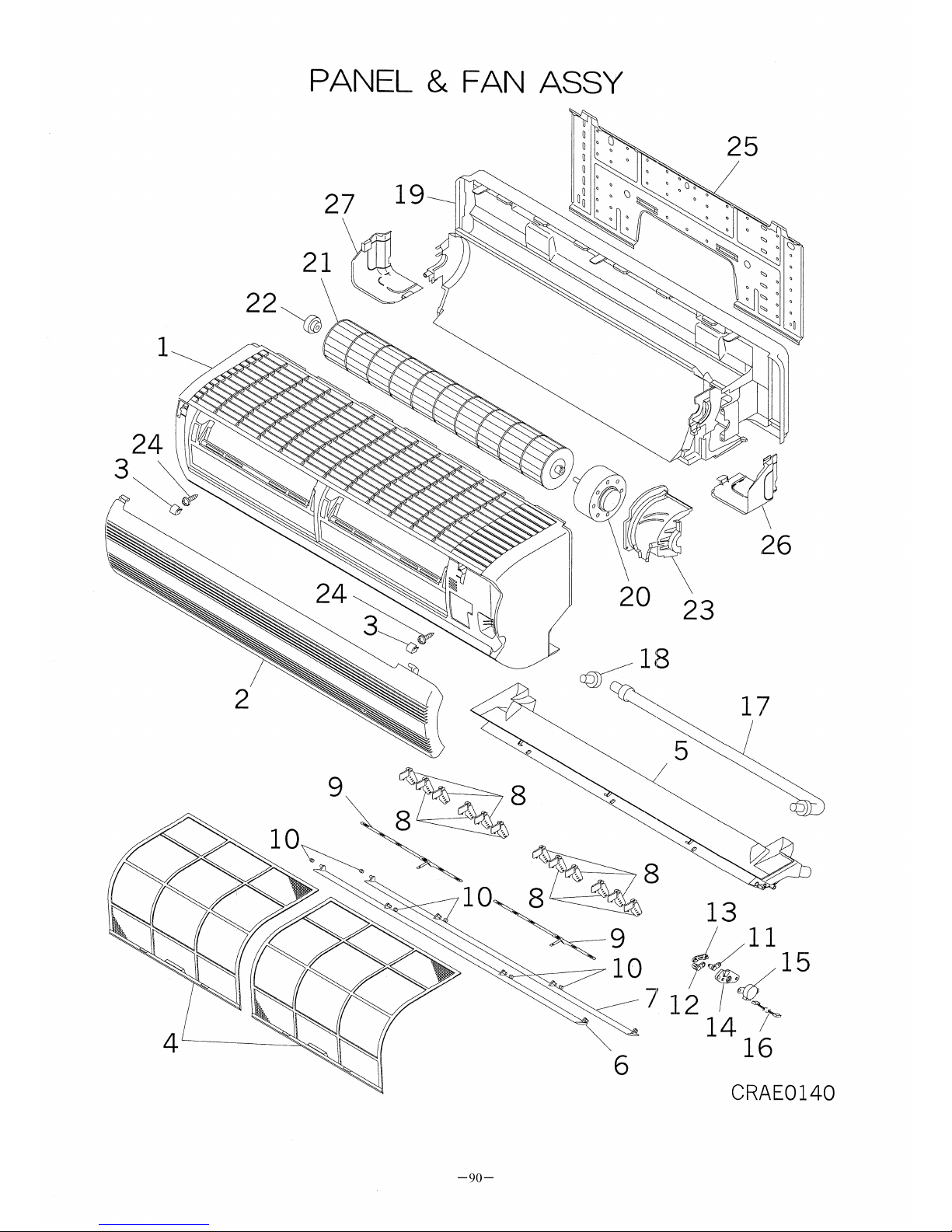
SRK10CDV-1,-4
Part No.
:RMA002F003
A
,RMA002F003
K
Recommendable Purchased Q'ty
10 30 50 100 500 1000
1~4
RMA102A003A
RMA102A003C
(-1)
(-4)
PANEL ASSY,FRONT 0 0 1 1 2
1
RKV122A100B
RKV122A100D
(-1)
(-4)
PANEL,FRONT 0 0 1 1 2
2 RKV435A501 GRILLE,AIR INLET 1 1 1 2 3
3 RKV129A007 CAP 2 0 1 1 2
4 RKV437A001 FILTER,AIR 1 1 2 4 8
5~18 RKV435A101 GRILLE ASSY,AIR OUT 1 1 1 2 3
5 RKV435A003 GRILLE,AIR OUTLET 0 1 1 2 3
6 RKV436A100 FLAP(A) 1 1 1 2 3
7 RKV436A101 FLAP(B) 1 1 1 2 3
8~9 RKV436A102 LOUVER ASSY 1 1 1 2 3
8 RKV436A103 LOUVER 0 1 1 2 3
9 RKV129A003 PLATE,CONNECTING 0 0 1 1 2
10 RKR935C001B COLLAR 10
11 RKV144A001 CRANK(A) 1 0 1 1 2
12 RKV144A002 CRANK(B) 1 0 1 1 2
13 RKV144A003 LINK 1 0 1 1 2
14 RKV129A005 BRACKET,MOTOR 1 0 1 1 2
15 SSA512T017 MOTOR,STEPPING 1
16 RKS504A100F HARNESS ASSY 1
17 SSA423A091 HOSE,DRAIN 1 1 1 2 3 SSA423A094
18 SSA326A041 PLUG 5
19 RKV111A001 BASE ASSY 1
20 SSA511J218 MOTOR,AC 1 2 2 4 8
21 SSA431G042 IMPELLER 1 1 2 4 8 SSA431G042A
22 SSA923C114 BEARING,PLANE 1 1 1 2 4 SSA923C091
23 RKV129A002 COVER(MOTOR) 1 0 1 1 2
24 SSA913A007A SCREW,TAP 10
25 RKV032A001 PLATE,INSTALLATION 1
26 RKV132A001A LID(R) 1
27 RKV132A002 LID(L) 1
RE.Q Substitute PartsPart NoNo. Part Name
-91-

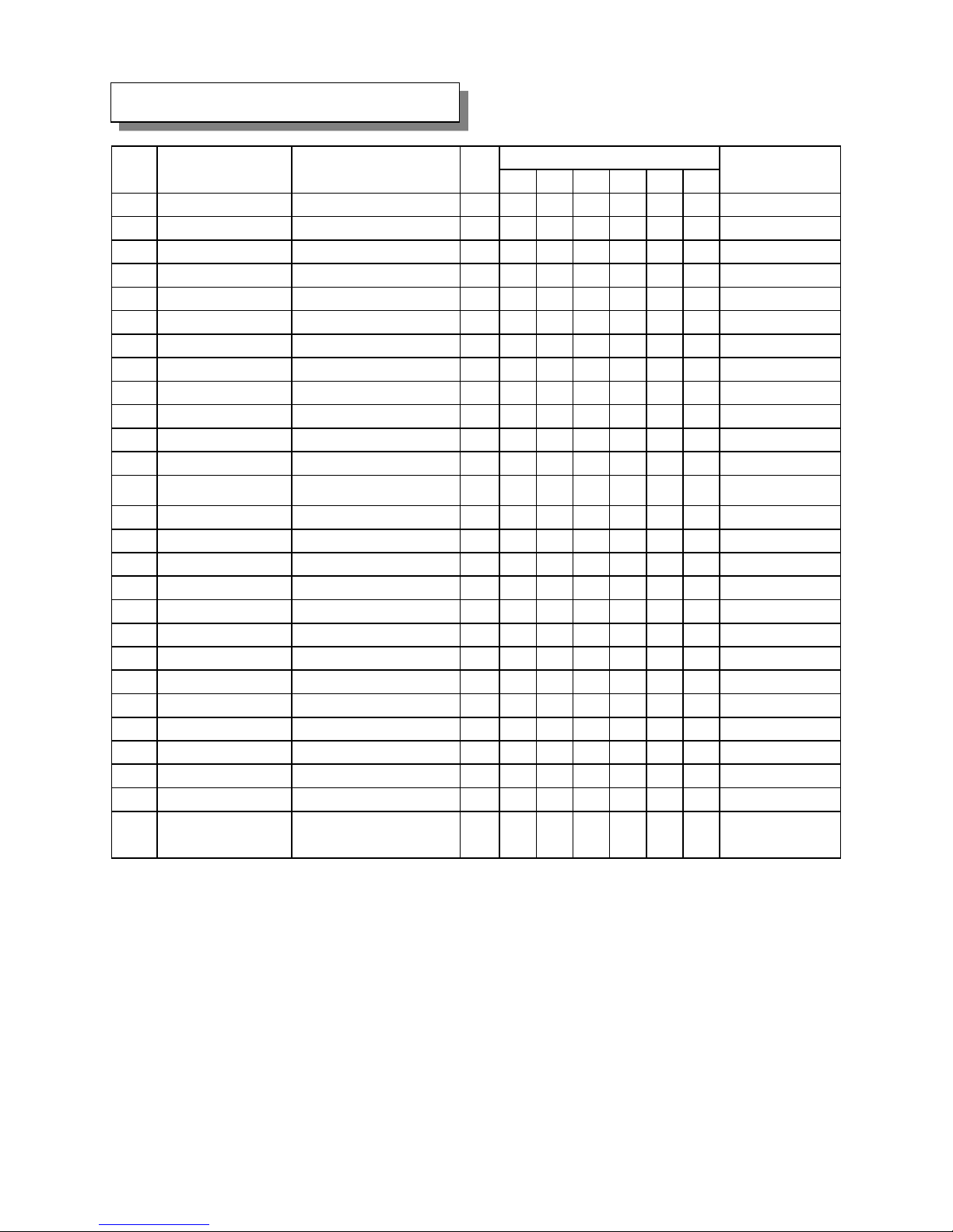
SRK10CDV-1,-4
Recommendable Purchased Q'ty
10 30 50 100 500 1000
1~8 RKV301A500K HEAT EXCH ASSY 1 0 0 0 1
2 RKV315D501 HEADER ASSY 0
3 RMA315A002 DISTRIBUTOR ASSY 0
4 RKV129A001 BRACKET(L) 1 0 1 1 2
5~7 RKV321A512A PIPE ASSY 1
6 SSA323F082 UNION(SLD) 1
7 SSA323F082A UNION(SLD) 1
8 RKV129A004 PLATE,BAFFLE 1 0 1 1 2
9 RKV142A500 BOX,CONTROL 1
10~12 RKV505A500V PWB ASSY 1 2 2 4 8
11 SSA555B041B VARISTOR 1 1 1 1 2
12 SSA564A072 FUSE(CURRENT) 3 1 1 2 4
13 SSA551A163F SENSOR ASSY 1 1 1 2 4
14 RKV504A500 HARNESS ASSY(POWER) 1
15 SSA561B713 BLOCK,TERMINAL 0
16 SSA554A441 TRANSFORMER 1 1 1 2 3
17 RKV503A100A DISPLAY ASSY 1 1 1 2 3
18 RKV505A100A PWB ASSY(DISPLAY) 0 2 2 4 8
19 RKJ941F001 SPRING,LEAF 20
20 RKV142A501 COVER 1
21 RMA008A003A PARTS,STANDARD 0
22 RKT502A420 CONTROL ASSY,REMOTE 1 2 3 5 10
23 RKT129A009 HOLDER,FILTER 2 0 1 1 2
24 RKT437A009 FILTER,CLEAN 1 1 2 4 8
25 RKT437A005 FILTER,LIGHT CLEAN 1 1 2 4 8
26 RMA012A001A MANUAL,INSTRUCTION 0
27
RMA011F003A
RMA011F003V
(-1)
(-4)
LABEL,MODEL NAME 0
No. Part Name RE.Q Substitute PartsPart No
-93-
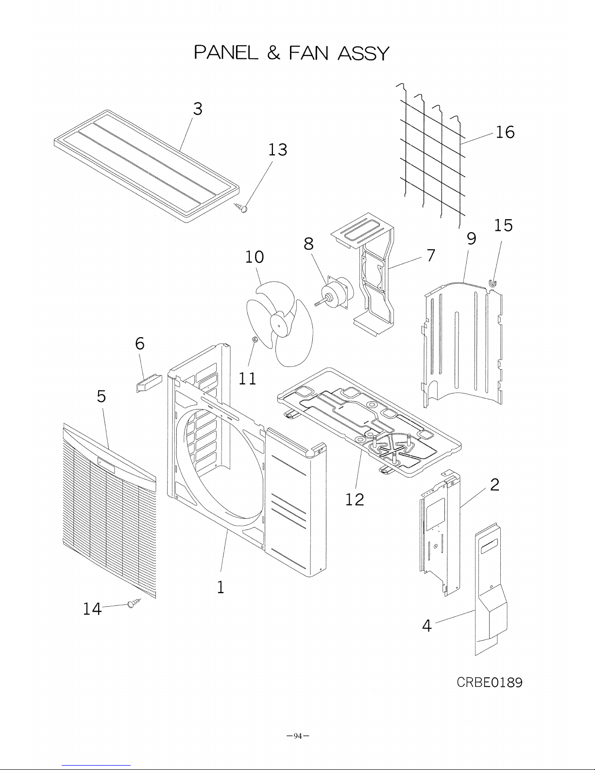

SRC10CDV-1,-4
Part No. :RMC003F003A,RMC003F003C
Recommendable Purchased Q'ty
10 30 50 100 500 1000
1 RCP122A500 PANEL ASSY,FRONT 1 0 1 1 2
2 RCP123A002 PANEL ASSY,SIDE 1 0 1 1 2
3 RCP124A500 PANEL ASSY,TOP 1 0 1 1 2
4 RCP132A001 PANEL,SERVICE 1 RCP132A002
5 RCP435A002A GRILLE ASSY,AIR OUT 1 1 1 2 3
6 SSA944B036 HANDLE 2
7 RCP116A001 BRACKET,MOTOR 1 0 1 1 2
8 SSA511C061C MOTOR,AC 1 2 2 4 8
9 RCP141A500 PLATE,BAFFLE 1
10 SSA431B213 PROPELLER 1 1 2 4 8
11 SSA914B007CC NUT,TH 10
12 RCP111A001 BASE ASSY 1
13 SSA913A034B SCREW,TAP 20
14 SSA913A034C SCREW,TAP 20
15 SSA947B019 GROMMET 5
16 RMC131A002 GUARD,FIN 1 0 1 1 2
Part No RE.Q Substitute PartsNo. Part Name
-95-


SRC10CDV-1,-4
Recommendable Purchased Q'ty
10 30 50 100 500 1000
1~3 RCP301A001H HEAT EXCH ASSY 1 0 0 0 1
2 RCP321A001 PIPE 0
3 RCP321A035A PIPE 0
4~5 RMC304A002 PIPING ASSY 0
4 RMC315B001 CAPILLARY 0
5 RMC315B005 CAPILLARY,SUB 0
6 RCK116A002 BRACKET(VALVE) 1 0 1 1 2
7 RMC381A001 VALVE,SERVICE(1/4" ) 1
8 RMC381A002 VALVE,SERVICE(3/8" ) 1
9 RCG151C008B INSULATION,COMP 1
10 RMC201A002 COMPRESSOR ASSY 1 1 1 2 8
11 SSA941C241 CUSHION,RUBBER 1
12 SSA914C013A NUT,FLANGE 20
13 SSA914C016 NUT,FLANGE 10
14 RSA947K003 COVER,TERMINAL 1
15 RSA932C002 GASKET,COVER 1
16 SSA552A832 CAPACITOR,RUNNING 1 1 1 2 4
17 SSA552A825 CAPACITOR,RUNNING 1 1 1 2 4
18 RMC533B001 PROTECTOR,MOTOR 1 1 1 2 3
19 AHA941D003 SPRING(PROTECTOR) 10
20 SSA561B713 BLOCK,TERMINAL 0
21 RWC504A083A WIRING ASSY 0
22
RMC011F002A
RMC011F002T
(-1)
(-4)
LABEL,MODEL NAME 0
RE.Q Substitute PartsPart NoNo. Part Name
-97-

 Loading...