

Mitsubishi Heavy Industries SC-SLA3-ER Technical Manual

-
3
-
AIR CONDITIONING CONTROL SYSTEM
TECHNICAL MANUAL
Collection data
Manual No. ’06
.
SC-T - 111
CENTER CONSOLE
SLA-3-ER (SC-SLA3-ER)
SLB-3-ER (SC-SLB3-ER)
-
1
-
CONTENTS
1. MODEL USED ALL SUPER LINK RELATED MODELS ................................. 1
2. SPECIFICATIONS ........................................................................................... 1
3. ACCESSORIES ............................................................................................... 1
4. EXTERNAL VIEW ............................................................................................ 2
5. INSTALLATION ............................................................................................... 2
6. FUNCTIONS .................................................................................................... 4
7. ELECTRIC WIRING ......................................................................................... 9
8. SELECTING A NEW PULSE UNIT .................................................................. 10
These technical manual cover Center Consoles SLA-3-ER and SLB-3-
ER. Concerning other air conditioning control systems, see page 675
in Part 5 (Air Conditioning Control System) of the
’06
TECHNICAL MANUAL
KX-4

-
1
-
Center Console SLA-3-ER, SLB-3-ER
1 MODEL USED ALL SUPER LINK RELATED MODELS
Name Model Remark
Center Console
SLA-3-ER
SLB-3-ER
SC-SLA3-ER
SC-SLA3-ER
If the SLA-3-ER and SLB-3-ER is buried, it
must be installed in a separately sold box (SLA3R-BX).
2 SPECIFICATIONS
Model
Item
SLA-3-ER, SLB-3-ER
(9)
Ambient temperature during use
Power supply
Power consumption
External dimensions
(Height⳯Width⳯Depth)
Net weight
Maximum number of connectable units
(Indoor units)
Outputs Inputs
LCD touch panel
(4), (5)
SL (Super link) Signal inputs
Gas, Power pulse input
(2)
Fire signal input
(2)
Demand signal input
(2)
Simultaneous operation
output
Simultaneous error output
Use with other central control units
0 ~ 40 °C
1 Phase 100V/200~240V 50Hz/60Hz
17 W
162 mm ⳯ 240 mm ⳯ 110 mm
2 kg
Maximum 48 units/system 3 systems = 144 units
Color LCD, 7 inches wide
3 systems
8-point pulse width 100 ms or more
1 point non-voltage a contact input continuous input (closed, forced stop)
1 point non-voltage a contact input continuous input (closed, demand control)
1 point maximum rated current 40 mA, 24 V
During full stop: Open; If even 1 unit is operating, Closed
1 point maximum rated current 40 mA, 24 V
Normal: If even one unit is abnormal, Open
(6)
(8)
Notes
(1) Some functions cannot be used depending on the indoor model used.
(2) The receiving side power supply is DC 12 V (10 mA).
(3) If the energy consumption calculation function is necessary, use the SLB-3-ER.
(4) The lifetime of the keying of touch panel is one million times.
The lifetime of LCD is about 20,000 hours. depending also upon the backlight OFF time setting. (The brightness will become half of the starting value.)
(5) The touch panel has an endurance of approximately 1 million times.
(6) In the environment setting screen, it is also possible to change the batch error output setting as open for normal and closed for error.
(7) The air conditioning charges calculations of this unit are not based on OIML, the international standard.
(8) • The center console SLA-2A series can be connected 1 unit per system.
• It cannot be combined with the center console SLA-1 series, SLA-200 series and the CHC-M series, SC-WGW-A series, SC-BGW-A series or SC-LIF
series,
SC-LGW-A series.
• Multiple SLA-3-ER and SLB-3-ER units cannot be connected on the same network.
(9) SLB-3-ER cost calculation results cannot be guaranteed.
(
10
) Working Environment
• Operating System
Microsoft
®
Windows® 2000 SP3, 4
Windows
®
XP
• Hardware
Pentium 300 MHz or greater
128 MB RAM
5 MB free hard disk space
1 USB (1.1 or 2.0) port
3 ACCESSORIES
Center console 1 unit
User's manual (CD-ROM)
Installation Instruction manual
Terminal
1 unit
1 unit
2 pieces
Pan head screw (M4)
Pan head screw (M4)
In case of embedding in a wall, the special box (SLA3R-BX) for embedding in a wall is required. (sold separately)
4 pieces for installing on the
control board (10 mm)
4 pieces for embedding in
a wall (40 mm)
• For SLB-3-ER
SLB-3-ER utility (CD-ROM) 1 unit USB Memory 1 unit
-
2
-
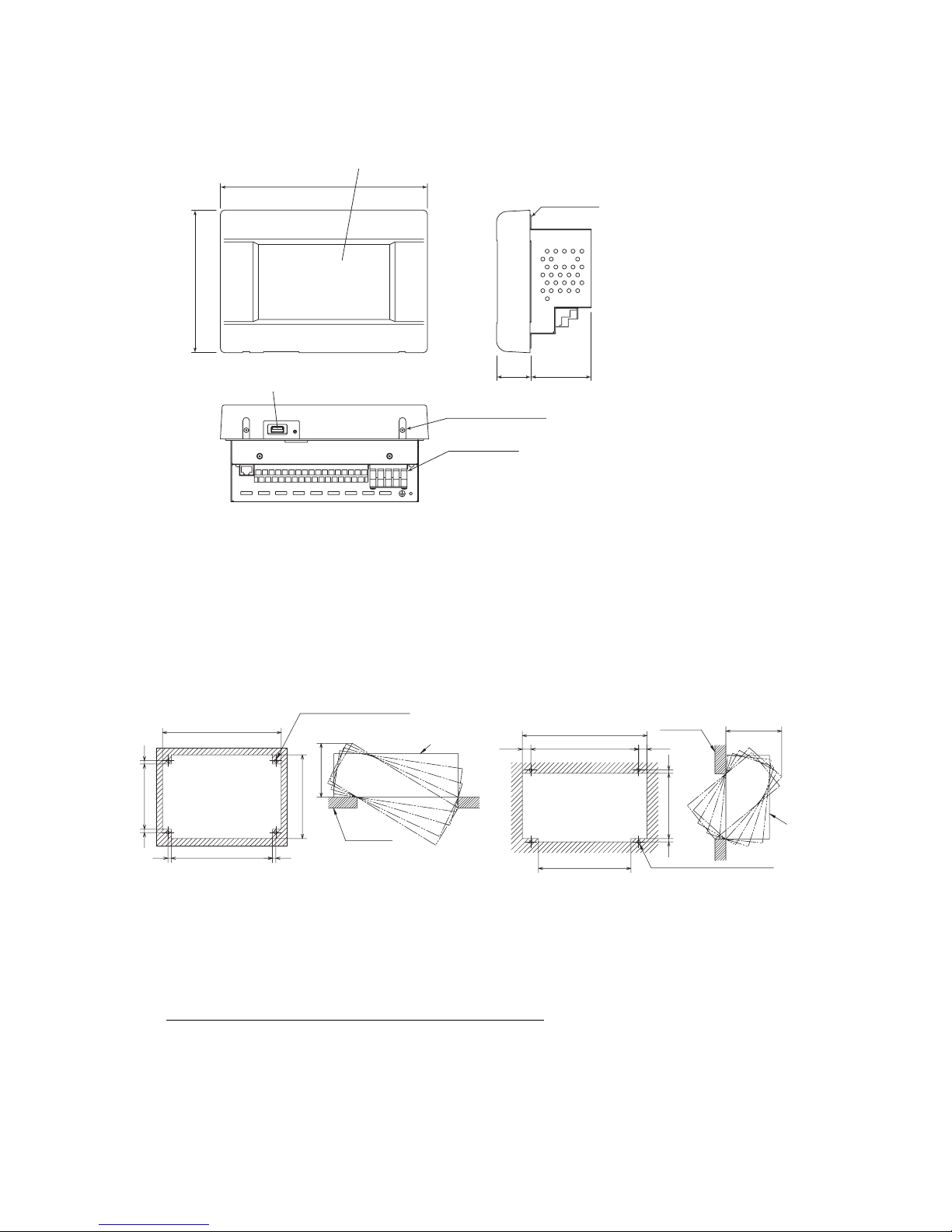
7040
240
162
7-inch wide color
LCD touch panel
USB
Upper case mounting
screws(2 screws)
Terminal block
Wall surface
5 INSTALLATION
<Way1><Way
2
>
Opening space
for the installation
Opening space
for the installation
Holes for the unit installaion
Holes for the unit installaion
4-ø6
218
66186
66
120
154
99
Inner wall
SLA3R-BX
229
170
198
15.5 15.5
4-ø6
66120
SLA3R-BX
Inner wall
105
4 EXTERNAL VIEW
Paint color:Pearl white
(a) In case of installing on the control board
1) Please use the control board of the size of 300mm ⳯ 400mm ⳯ 120mm or larger.
2) Please be sure to lock the control board to protect persons from the electric shock.
3) Please do not use any heat insulation material on the control board.
4) If you use it, accumulated heat will cause the center console to malfunction.
(b) In case of embedding in a wall
Please be sure to use the special box, SLA3R-BX (sold separately) to secure sufficient air circulation space. If the box is
unused, the center console will not work properly because of heat buildup inside the box. Please be sure to use for protecting
persons from the electric shock.Please check that the sufficient space is available in the wall.
When the inside of the wall is divided and have a cavity, please create space more than 0.08m
3
. Refer to the next page.
If there is no partition on the left, right, top and bottom of the center console, please create a space that is 105mm ordeeper.
When you cannot create the sufficient space or thickness of the wall is above 15mm, please install the center console on the
control board.
Before the installation, shut off the power supply to avoid an electric shock.
Please locate or protect so that the unit will not be forced against wiring.
(1) Installation place
Install this unit indoors without the influence of the electromagnetic wave, or splashing such as water and dust.
Necessary clearance is 200mm or more beneath the center console and 500mm or more in front of the center console.
(2) Installation space
Please choose one of two ways.
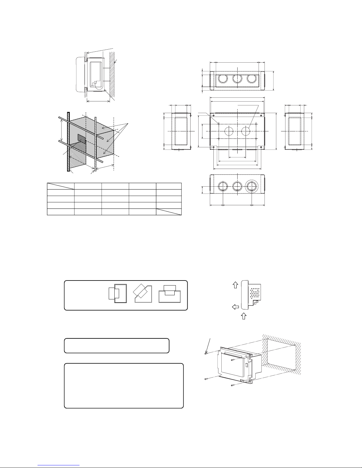
-
3
-
Example1
Example2
Example3
Minimum
a(Height)(mm)
900
180
0
100
0
600 or larger
b(Width)(mm)
800
400
400
400 or larger
c(Depth)(mm)
110
110
200
110 or larger
0.08
0.08
0.08
Beam of
building
Inner wall
SLA3R-BX
more than
105mm
<No partition>
a
b
c
Inner wall
Partition
Center
console
<With partition>
䢇SLA3R-BX (Sold separately)
4-ø6
2-ø35
15
20 113
132
30
153
113 2020
60
20
50 15
80
(Knock out)
Incorrect IncorrectCorrect
1 Caution
1
2
3
1 Caution
2 Caution
(e) In case of installing on the control board
(f) In case of embedding in a wall
Please be sure to use the special box, SLA3R-BX (sold separately).
25
15 48 17
228
17 48 15
220
70
155
170
198
54 120 54
178 25
Space(m3)
(3) Installation method
(a) Embed signal wire and power supply wire in a wall beforehand.
(b) Connect wires to the terminal block.
(c) Confirm power supply voltage and connect correctly.
(d) Remove the upper case
1) Take out two screws using a cross slot screwdriver. (Don't lose the screws)
2) Pull the upper case a little forward and push above. Then, upper case can be removed.
M4 screws, 4 pieces
(accessory of the unit)
Fix the unit to the SLA3R-BX with the M4 screws. (4 places)
Wire separately the power supply wire and the signal wire for
preventing malfunctions.
Please do not install other units on the same
control board that will cause temperature rise.
Please do not
install facing
upward or in
slanted position.
Please do not install multiple controllers on the
same control board. They can cause the temperature
rise of the control board interior and the center
consoles will not work properly.
When there is no choice but to install the multiple
controllers,please adjust the tempereture inside the
control board 40 degrees or less. (for example
cooling fan installation)
 Loading...