

Mitsubishi Heavy Industries SC-SL2NA-E, SC-SL3NA-AE, SC-SL3NA-BE Technical Manual
AIR CONDITIONING CONTROL SYSTEM
SC-SL2NA-E
SC-SL3NA-AE
SC-SL3NA-BE
CENTRAL CONTROL
TECHNICAL MANUAL
Manual No. ’10
•
SC-T-154
-
1
-
’10 • SC-T-154
CONTENTS
1 CENTRAL CONTROL SC-SL2NA-E ..................................................................2
2 CENTRAL CONTROL SC-SL3NA-AE and SC-SL3NA-BE ............................
10
3 TROUBLESHOOTING ...................................................................................... 36
4 CONNECTION EXAMPLE ................................................................................
38
SC-SL3NA-AE, BE
SC-SL2NA-E
00010203040
5 ~ 81112131415 ~ 8202122232425 ~ 8
0001020
311 (3)
(1)
SC-SL3NA-AE, BE
SC-SL2NA-E
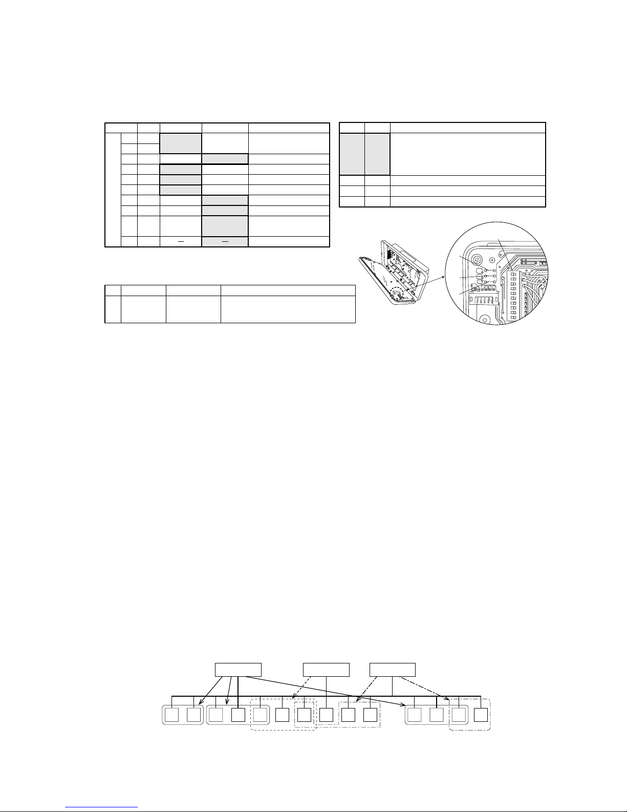
Number of units in combinations of SC-SL1N-E, SC-SL2NA-E and SC-SL3NA-AE, BE
(per system)
Check indicator table
In case of new SL (Super Link)
In case of previous SL
Notes (1) In case of previous SL, since SC-SL3NA-AE, BE is for connection of 3 Super Link systems, one unit of SC-SL2NA-E can be
connected to each system.
(2) Number of units in combination as shown above is applicable to when the indoor units being controlled by each central control are
not duplicated. When controlling the same indoor units with a plural number of central controls, it may affect the allowable
number of indoor units for connection. For further details, please consult your dealr.
Description of trouble
Location of
trouble
Outdoor unit control PCBIndoor unit control PCB
Red LED Green LEDRed LED Green LEDRed LEDError code
Repair method
Replacement
SL2NA-E
SL3NA-AE, BE
SL2NA-E
SL3NA-AE, BE
Communication error (Defective communication circuit on the main unit of
SL2NA-E or SL3NA-E)
•
Keeps flashing Keeps flashing Keeps flashingStays OFF Stays OFF
-
2
-
’10 • SC-T-154
1 CENTRAL CONTROL SC-SL2N-E
(1) Specification
Definitions of new and previous Super Link (new and previous SL)
New Super Link (new SL): All units connected to the network are models compatible with New Super Link
(KXE6 model or later models. Central controller and I/F are from “N” models.) and
SL setting is unchanged from shipment (“New” or “AUTO”).
Previous Super Link (previous SL): Units do not meet the conditions of New SL. When even a single unit connected to
the network is an earlier model than KXE4 or the connected model is not compatible
with New SL. Setting explained in Note (5) is required.
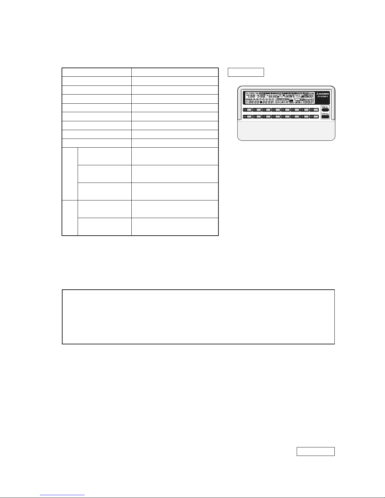
Appearance
Notes (1) Some of functions may not be used depending on the indoor unit. (See page 4 (2).)
(2) For the specification of relay being procured at site, select a product that can assure the minimum application load of DC 12 V, 10 mA or less.
Even if it is reset within 2 minutes after input, the input state is retained.
(3) For the specification of relay being procured at site, select a product with the rated voltage at DC 12 V, max. power consumption at DC 0.9 W or
under (80 mA or under).
(4) Dimension +35 in ( ) indicates the embedded dimension.
(5) When the connecting network consists of previous Super Link, it is necessary to set the control selector switch SW5 to OFF.
(Factory default is ON.)
Description
Model name
Applicable model
Ambient temperature in operation
Power supply
Power consumption
External dimensions (HWD)
Net weight
Max. number of connectable indoor units
CENTRAL CONTROL SC-SL2NA-E
SC-SL2NA-E
Super Link compatible indoor unit
(1)
0 ~ 40˚C
1 phase, 100 ~ 240 V, 50/60 Hz
7W
120mm215mm(2535)mm
(4)
1kg
New SL: Max. 64 units, previous SL: Max. 48 units
1 point, Non-voltage contact “a” input
(Open /Close: RUN, Close /Open: STOP)
1 point, Non-voltage contact point “a” input,
continuous input
(Close; Center & Stop all units)
1 point, Non-voltage contact “a” input,
continuous input
(Close: Center & Fan mode)
All indoor units at STOP; Open
If there is any unit operating; Close
All indoor units normal: Open
If there is any abnormal unit; Close
Input
Output
External timer input
(2)
Emergency stop signal input
(2)
Demand signal input
(2)
Operation output
(3)
Error output
(3)
PJ Z 00 0 Z2 8 1
-
3
-
’10 • SC-T-154
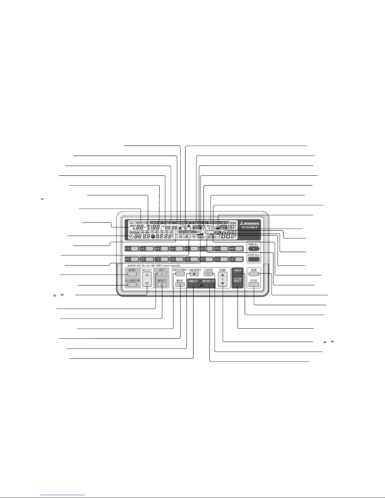
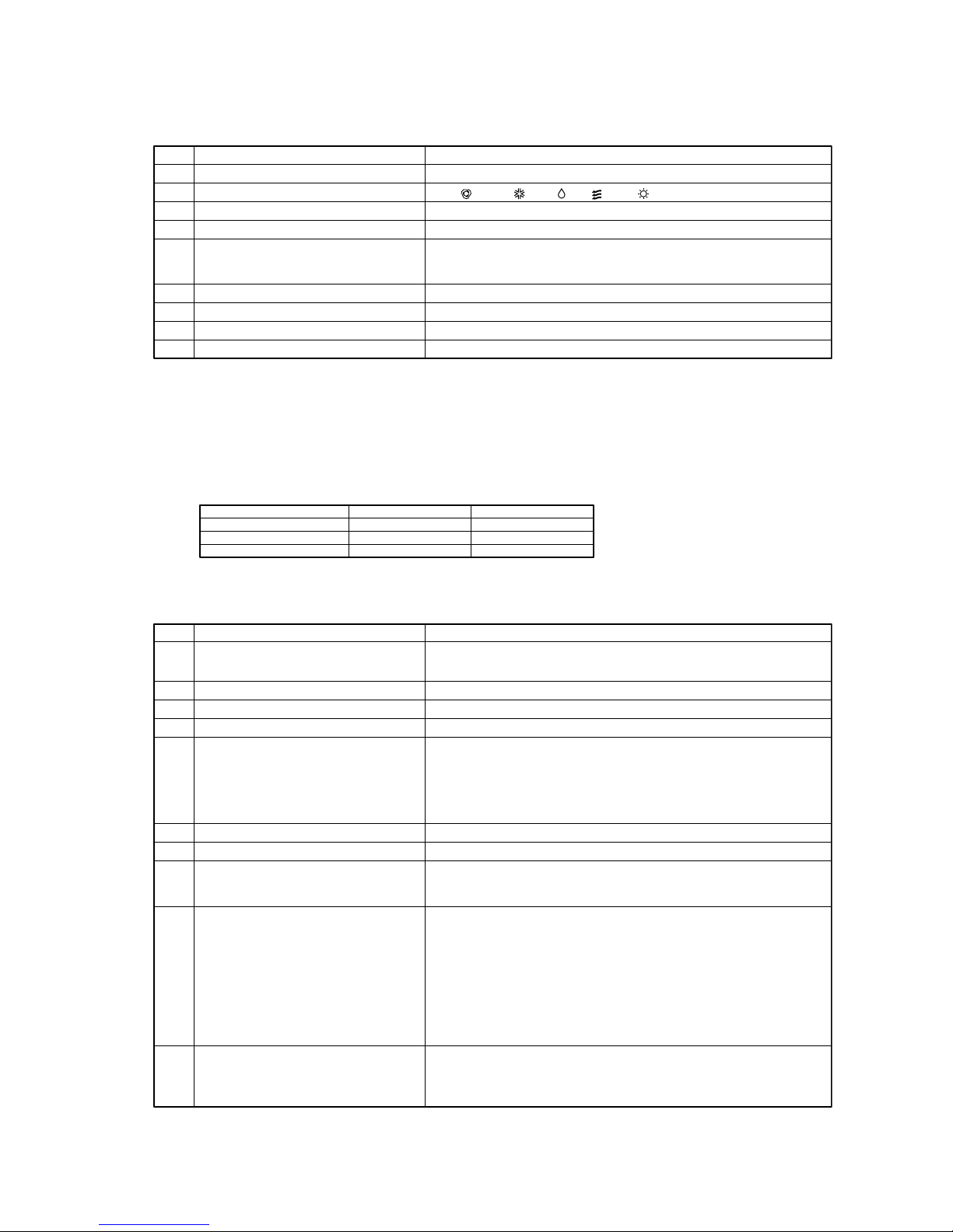
CENTER / REMOTE display
Displays which is in effect, the central control or the local remote controllers.
PROGRAM SET display
Displayed when a program is being set.
TIME SET display
Displayed when the current date and time are being set.
TIME display
Displays the time.
GROUP SET display
Displayed when the units to be managed are being set.
Program days of the week display
is displayed above today’s day of the week and _ is displayed under each day of
the week for which the program has already been set.
ALL / GROUP / ONE display
Displays whether operations on this central control are f
all units, one group of units, or one unit.
or
GROUP No. / UNIT No. display
Displays the group number and indoor
unit number being set or monitored.
PROGRAM display
Displays the contents of the program set.
PROGRAM No. display
Displays the numbers of the programs that have been set.
MODE display
Displays the operation mode.
DEMAND display
Displayed during demand input.
MENU button
This button selects the setting mode.
ALL / GROUP / ONE button
This button selects ALL, GROUP, or ONE to be operated.
SELECT (
or ) button
This button is primarily used for selecting the group number
or unit number.
SET button
This button conìr ms settings.
RESET button
Pressing this button during a setting operation cancels the last step
CENTER / REMOTE button
This button selects centralized control or local remote controller.
MODE button
This button selects the operation mode.
FAN SPEED button
This button adjusts the fan speed.
DEMAND SET button
This button sets the indoor unit for demand.
REMOTE CONTROL OPERATION ENABLE / DISABLE display
Displays items for which remote controller operation is disabled.
HOLIDAY SET display
Displayed when a program for holidays is set.
INVALID INPUT display
Displayed when a button input is invalid.
FAN SPEED display
Displays the fan speed.
MAINTENANCE display
Displayed when there is a managed unit requiring a check.
PROGRAM CONFIRM display
Displayed when a set program is displayed.
CHECK display
Displayed when there is a unit being managed in which an error has occurred.
CLEAN FILTER display
Displayed when there is a unit being managed
whose ìlter needs to be cleaned.
ROOM TEMPERATURE display
Displays the room temperature.
OUTDOOR UNIT No. display
Displays the outdoor unit number in the ROOM
TEMPERATURE display section.
MANAG. UNIT NUM display
Displays the number of units managed in the
SET TEMPERATURE display section.
SET TEMPERATURE display
Displays the set temperature.
LOUVER display
Displays the louver direction.
TIMER INPUT display
Displayed when an external timer is being input.
RUN button
This button runs indoor units.
STOP button
This button stops indoor units.
CHECK button
This button is for service.
During normal operation, do not press this button.
FILTER RESET button
This button resets the CLEAN FILTER display.
Press this button after cleaning the air ìlter .
TEMP (
or ) button
This button sets the temperature.
LOUVER button
This button adjusts the louver direction.
TIMER INPUT SET button
This button sets an indoor unit for which operation by external timer is enabled.
The diagram below shows the central control with its cover open.
Also, for the sake of the explanation, all the contents of the LCD display section are shown.
-
4
-
’10 • SC-T-154
Notes (1) Don’t use the auto mode on any indoor unit other than those connected to the simultaneous heating & cooling 3-pipe system or single PAC.
(2) Do not set the set point at 0.5˚C intervals in case this product is used with RCD type wired remote controller.
It would cause malfunction of the wired remote controller. Please make sure to set at 1˚C intervals.
(3) This function can be applied to the indoor units, which are the model KXE4 or later, SC-ADN-E or later and to the remote controller, which is the model
RC-E1 or later. (For models earlier than the above-mentioned, the function becomes invalid because the indoor unit and remote controller cannot receive
the instruction even though the setting can be displayed.)
Since setting is overwritten in SL2NA-E even if setting is done from the remote controller, set using SL2NA-E.
(4) This function can be applied to the indoor units, which are the model KXE6D or later, SC-ADNA-E or later.
For the previous indoor units, it is not possible to set the 4th mode but other setting is possible as before.
4th fan speed setting is “impossible” before shipment, so changing to “possible” is needed for 4th fan speed setting from this Central control.
4th fan mode of indoor units operating at 4th fan mode can be displayed on SC-SL2NA-E whose 4th fan mode setting is “impossible”.
(SW7 changes “possible” or “impossible” for 4th fan mode setting from SC-SL2NA-E.)
“Possible” needs the indoor units, which are the model KXE6D or later, SC-ADNA-E or later.
Item Description
RUN/STOP
Operation mode
Temperature setting
Center/remote
Fan speed
Fan direction
Filter reset
Error reset
No.
1
2
3
4
5
6
7
8
9
Individual Lock/Unlock settings enabled in
Function Setting of remote controller.
Performs operation or stop control.
Sets Auto
(1)
, Cool, Dry, Fan or Heat.
Sets temperature in the range of 18 ~ 30˚C (0.5˚C interval)
(2)
Sets the center, remote or center remote.
Sets 4th, 3rd, 2nd, 1st speed.
Sets the auto swing ON/OFF and positions 1 ~ 4.
Controls the filter sign reset.
Puts out the error sign with the RUN or STOP operation
SC-SL2NA-E (before shipment)
SC-SL2NA-E (SW7 is ON)
SC-SL2N-E (old model)
4th fan speed settiing
Impossible
Possible
Impossible
4th fan speed display
Possible
Possible
Impossible
Sets the permission/prohibition on the basis of remote controller function.
Sets the permission or prohibition for RUN/STOP control, operation mode setting,
temperature setting or each functions.
(3)
Notes (1) If “Check” button is pressed when the icon is turned on by 8, 9 and 10, display will change automatically to the display of corresponding unit No.
When 8, 9 and 10 are mixed, 10 takes the highest priority. When all of 10 is reset, display is in the order of 9 to 8.
(2)
When the operation time exceeds 9,800 hours, it displays Inspection 2 and, if it exceeds 10,000 hours, Inspection 1 is displayed. (GHP only)
Item Description
RUN/STOP status
Operation mode
Temperature setting
Room temperature
Fan speed
Fan direction
Filter sign
No.
1
2
3
4
5
6
7
8
9
10
Displays the operation mode of unit No. on display.
Displays the setting temperature of unit No. on display.
Displays the suction temperature of unit No. on display.
Monitors the RUN/STOP status of unit No. on display.
With LED for each group, it monitors the RUN/STOP status of each group.
When the filter cleaning time is exceeded on one or more indoor units, the filter
sign icon is turned on. When it corresponds to the unit No. on display, the icon
blinks.
When there is one or more indoor units requiring maintenance, the maintenance
icon is turned on.
There are 4 types of operation of Inspection, Inspection 1, Inspection 2 and Back up.
Inspection :There is an indoor unit requiring maintenance.
Inspection1 :The operation time (GHP outdoor unit) exceeds 10000 hours
Inspection2 :The operation time (GHP outdoor unit) exceeds 9800 hours
Backup :Connected outdoor unit is on backup operation.
Preference order of display is as shown below.
Backup > Inspection 1 > Inspection 2 > Inspection
When it corresponds to the unit No. on display, the icon blinks.
When any error is detected on one or more controlled indoor units, the error icon
is turned on. If it corresponds to the unit No. on display, the icon blinks and the
display shows the error code, date/time of error occurrence, connected outdoor
unit No. (KXE6 type or later).
Maintenance
(2)
,
(Inspection, Inspection 1, Inspection 2 and
Backup)
Permission/prohibition on the basis of
remote controller function
Displays the status of permission/prohibition setting for each remote controller
function of unit No. on display.
Display the permission/prohibition of the RUN/STOP control, operation mode
setting and temperature setting.
Permission/prohibition setting for each function as set from the remote controller
is not reflected because it is overwritten from SC-SL2NA-E.
Trouble (Error)
Displays the fan speed of unit No. on display.
Displays the auto swing ON/OFF setting and position setting of unit No. on display.
(2) Operation and setting
Operation or setting is implemented individually, in the unit of group or in a batch for air-conditioners up to 64 units or 16 groups.
(3) Status monitor
Status monitor may be applied in the unit of group or air-conditioner.

-
5
-
’10 • SC-T-154
Item Description
Group setting
Individual setting
Time & date setting
Alarm history
Demand control
Emergency stop
Power restoration control
Power failure compensation
No.
1
2
4
5
6
7
8
9
Registers controlled air-conditioners (max. 64 units) to max. 16 groups.
Sets air-conditioners which are subject to the control of SC-SL2N-E, but are not
registered to any group.
Sets all air-conditioners connected to this unit at “Stop” and “Center” with an external emergency signal. As the emergency signal is cancelled, the center/remote
setting is returned to original state but all units stay “Stopped”
The group setting, individual setting, program timer setting, holiday setting, external timer setting, demand setting and operating condition (RUN/STOP, operating
mode, temperature setting, Center/Remote, remote controller permission/prohibition and airflow volume) are retained regardless of the length of power failure,
The clock time is compensated if the power interruption is not longer than 48
hours. If the current time is not displayed after the power restoration following a
power interruption exceeding 48 hours, set again the current time. Since the clock
time is not retained at the power restoration after a power interruption exceeding
48 hours, the power restoration control in Item No. (9) (a) does not operate.
Allows changing the power restoration process setting.
Program timer preferred: When SW1 and SW2 are turned ON. RUN/STOP and
setting temperature returns to the program timer just before the time of power
restoration on the day when the power supply is restored, or other states (operation mode, etc) return automatically with the priority given to the states before
the power failure (See ).
When no program timer is set before the power restoration on the day of power
restoration, it is restored with the priority given to the states before the power
failure (See ).
State before power failure preferred: When SW1 is turned ON and SW2 is
turned OFF. Each indoor unit returns automatically to the state before the power failure.
Any indoor unit running before the power failure starts its operation.
No power restoration processing: When SW1 and SW2 are turned OFF. SC-
SL2N-E does not perform timer the power restoration processing upon restoration of the power supply.
Sets the clock used for program timer or other.
•Year/Month/Date/Hour (24-hour basis) /Minute
Changes preset air-conditioners to “Fan” and “Center” with external demand signals. When the demand signal is cancelled, it returns to the state just before entering the demand control (operation mode and center/remote setting).
Displays the error history of around. 100 cases for each air-conditioner.
(5) Administration and control
(6) Outline drawing
010902
10
031104
12
05
13
06140715
169
215
25
35
120
87
�Resin color: Pearl white
(close to Munsell N-8.5)
(4) Program setting
Operation program can be set in the unit of group. It is possible to register the ON/OFF time or ON time + Temperature setting at
4 times a day. Operation time can be designated in the unit of minute.
-
6
-
’10 • SC-T-154
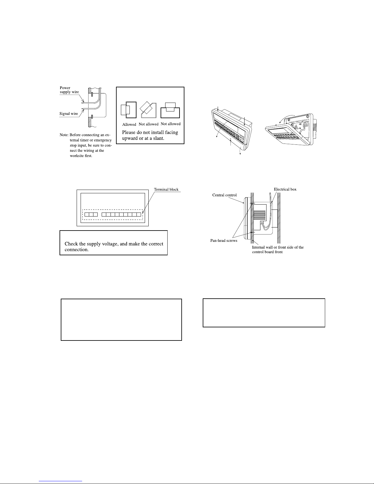
(7) Installation procedure
(a) In case of embedding in a wall, first, embed the power supply
wire, signal wire, and electrical box.
Keep the power supply wire and signal wire separated to
prevent malfunctions.
Caution
(b) Open the top case by following the procedure below.
①
Grasp the indentations on the right and left sides, and
pull forward to open the cover downward.
②
Use a phillips-head screwdriver to remove the screw.
(Be careful not to lose the screw.)
③
Open the top section in the direction 4 while gently
pressing the top section.
3
3
4
2
1
4
(c) Connect the power supply wire to the terminal.
(See section
(8) Electrical wiring.
)
(d) Use the supplied pan-head screws to secure the central
control to the electrical box or control board.
Caution
The back of the central control
(e) Use a precision screwdriver to make the control selector
settings.
(For details, see section
(10) Control switch selection.
)
(f) Peel off the protective sheet on the screen of central control.
(g) Insert the top case back into its original location in the bottom
case as before, and tighten the case mounting screws [(b),
②
].
This completes the installation procedure.
Caution
The case and power supply kit are an integrated unit.
Please do not separate them.
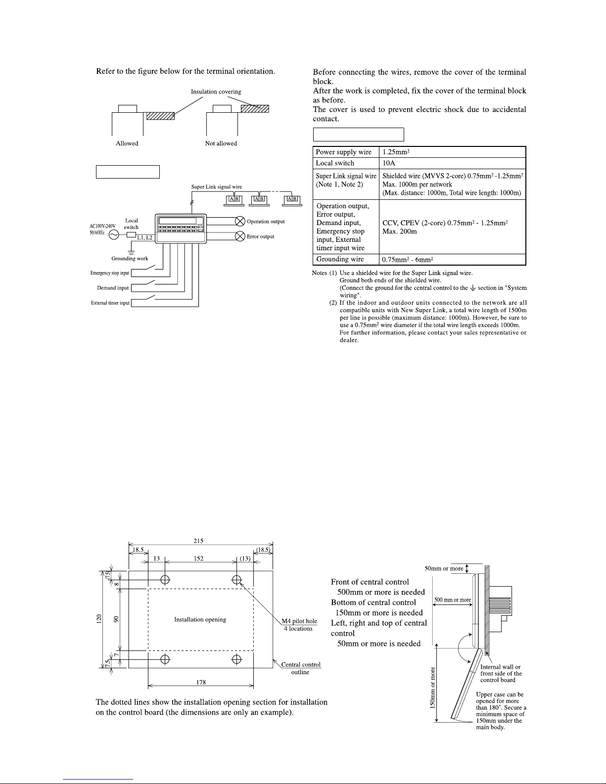
(8) Electrical wiring
For safety reasons, please use the round crimping terminals with insulated sleeves for connecting all wires to the central control.
c
Please do the grounding work. Please do not connect earth line with gas pipes, water pipes, lightning rods and grounding line of
telephone.
c
Please do not turn on the power supply (local switch) until all of the work is completed.
c
Please wait at least two minutes after the indoor and outdoor units are turned on before turning on the power supply.
c
Except for the central control in the figure, all of the components are obtained at the site (wires, switches, relays, power supply,
lamps, etc.).
c
Please be sure to build the breaker which is easily accessible with building equipment's wiring.
c
Please be sure to use the supplied round crimping terminals when connecting wires to the power supply terminal block and
Super Link terminal block.
c
Please use demand input device, emergency stop input device and external timer input device comply with a relevant IEC safety
standard.
Important
Please peel off the protective sheet on the air
conditioner screen when transferring the central
control to the customer. Peel off before mounting
the top case.
-
7
-
’10 • SC-T-154
Wiring Outline
Wiring specifications
(9) Installation work
Please install the central control after turning off the power for fear of electric shock.
Please arrange or protect the wiring so that excessive force is not applied to the electrical wires.
Control PCBs (printed circuit boards) are mounted to both the top and bottom cases.
Be careful that you do not damage the PCBs when using a screwdriver and other tools.
The PCBs can be damaged by static electricity, and so be sure to discharge any static electricity accumulated on your body before
starting the work.
(a) Installation place
Please install in an indoor location that is not exposed to electromagnetic waves, water, dust, or other foreign substances.
The operating temperature range of this product is from 0˚C to 40˚C.
Install in a location where the ambient temperature remains within the operating temperature range.
However, if the operating temperature range is exceeded, be sure to implement corrective measures such as installation of a
cooling fan.
Be aware that continued usage of this of this central control outside the operating temperature range can result in operation
problems.
(b) Space required for installation
Service space
-
8
-
’10 • SC-T-154
(c) In case of installing on the control board
Please be sure to lock the control board to protect persons
from the electric shock.
Avoid usage of heat-retaining materials and heat-insulating
materials because these can result in heat buildup and
adversely affect the operation of the central control.
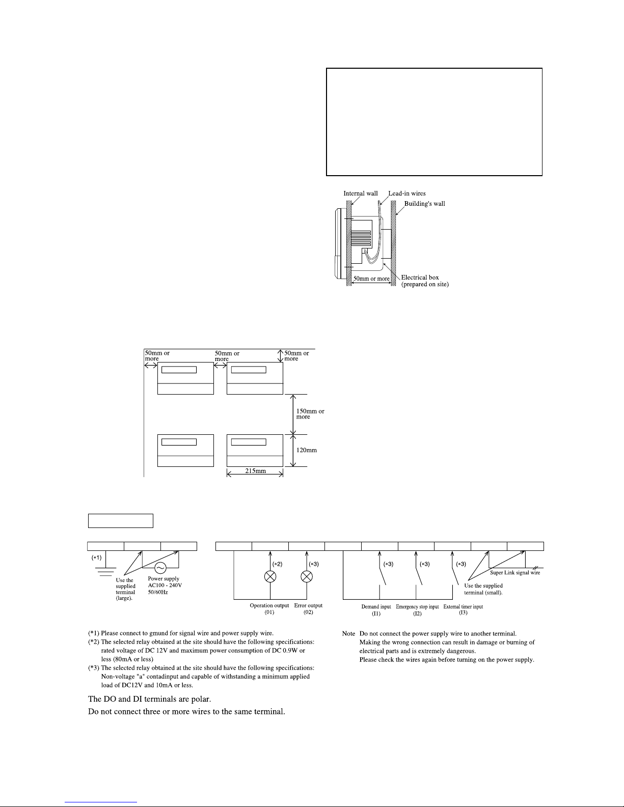
(d) In case of embedding in a wall
Please check that there is sufficient space inside the wall.
If the temperature inside the wall exceeds 40˚C, install the
central control on the control board.
Caution
Please do not install devices that can cause the ambient
temperature to rise in the same control board. Also, do
not install multiple controllers in the same control board.
These can cause heat to build up and result in false
operation. If multiple central control must be installed in
the same control board, take corrective measures to ensure
that the temperature in the control board does not rise
above 40˚C such as by installing cooling fans.
When performing the continued installation of multiple controllers, be sure to obtain the distance between units and service
space as shown in the figure.
System wiring
1 2 3 4 5 6 7 8 9 10 11 12
L1 L2/N COM DO1 DO2 COM DI1 DI2 DI3 A B
-
9
-
’10 • SC-T-154
(10) Control switch selection
It is possible to change the setting as follows by settings of the PCB switches SW1 to SW10, J1, J2, and J3 on the central
control.Please change the control on site as necessary. It is recommended to change the setting by using a precise driver.
(a) Switch
(*1) Switching is needed if the connection is previous Super Link.
Actual type of network connection (New or previous Super Link) depends on the models of indoor units and outdoor units, etc. Please contact the agency or
the Sales representative.
(*2) When J1 is disconnected, the Center/Remote does not be set from this central control. Please disconnect if multiple central controls are installed and another
main central control exists.
When J1 is disconnected data is sent for the blower only during demand input (nothing) is performed when SW6 is off) and for stop only during emergency
stop input
J1
Function
When disconnected
Short circuit (default)
Setting not possible
(Including during
external input.)
Setting
possible
SW1 to 10
(Left-OFF, Right-ON)
J1
J2
J3
Center/Remote setting
(*2)
(Including the allowed/prohibited settings
of each remote control function)
1
2
3
4
5
6
7
8
9
10
SW No.
SW
Description
(Keep at OFF)
Operation after
emergency stop cancel
The units
have stopped
Return to the
original status
4th fan speed set
Error history display
Sending of data during demand input
Filter sign display on/off
Automatic mode display
New/Prev. Super Link
(*1)
Power failure
compensation function
OFF
Month. Day Time
See table
at right
Auto mode cannot be set
No display
Previous
Center
ON
See table
at right
Auto mode can be set
setting not possible
setting possible
Display
New
Center & Fan
Time Month. Day
ON
ON
OFF
ON
ON
ON
OFF
OFF
OFF
OFF
Default
1
2
3
4
5
6
7
8
9
10
SW-1 SW-2
ON
ON
OFF
OFF
ON
OFF
ON
OFF
Sending of operation status before power failure
(Do not make this setting.)
No data is sent when power comes back on
Function
Sending of program settings when power comes back on
(The operation status before the power failure is sent if
there is no program when power comes back on.)
Power failure compensation function selector
(b) Jumper wires
(11) Setting the control target units
Make the settings for the units to be controlled by the central control.
For the setting procedure, see the user’s manual attached to the central contrl.
At shipping, none of the units are set as target units for control, and so the units to be controlled by this
central control must be set as control target units.
Three types of settings are available.
①
Units are selected as control targets for central control and controlled as a group
/
Group setting
②
Units are selected as control targets for central control but not grouped
/
Individual setting
③
Units are not selected as control targets for central control
/
Not target units for control
(or units will be controlled by another central control)
Be sure to set the current time. This is needed for the program settings and error history display.
Turn on the power and press the three buttons (MENU, RESET, GROUP No. 10) at once more than five second, that can
initialize the setting contents.
c
Group control when using multiple units
This central control can control up to 64 target units (up to 48 units when using the previous Super Link setting). Multiple
central controls must be installed to control 65 or more air conditioner units.
When connecting multiple central controls on a single network, any group settings can be made for each central control.
1 2 3 4 5 6 7 8 9 10 45 46 47 48
a-Gr1 a-Gr2
b-Gr1
c-Gr1
c-Gr16
a-Gr16
SC-SL2NA-E SC-SL2NA-E SC-SL2NA-E
a b c
-
10
-
’10 • SC-T-154
2 CENTRAL CONTROL SC-SL3NA-AE and SC-SL3NA-BE
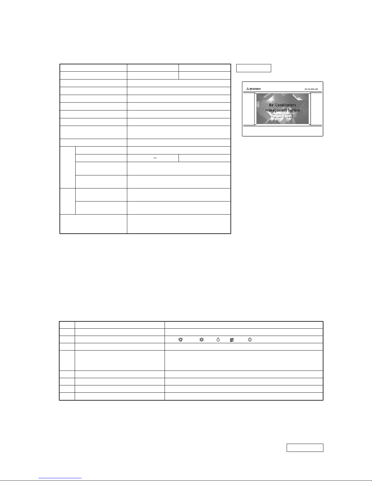
(1) Specifications
Appearance
Notes (1) Some of the new functions cannnot be used depending on the indoor unit model.
(2) 70 indicates embedded portion in the wall.
(3) The receiving side power supply is DC12V (10 mA).
(4) When the energy consumption calculation is required, use SC-SL3NA-BE.
(5) The life of LCD backlight is around 20000 hours, though it depends also on the setting of backlight OFF time. After that its brightness decreases to
1/2 of normal condition (ambient temperature at 25 ˚C).
(6) Durability of touch panel is around 1 million times.
(7) On the “Function Setting” screen, it is possible to change the batch error output to normally Open and Close at error occurrence.
(8) The energy consumption calculated by this unit does not conform to OIML, and there are no guarantees concerning the results of the calulations.
This unit calculates only energy consumption distribution (gas, electric power).
You need to calulate the air-conditioning rates.
(9) For the editing software and contents, refer to the Technical manual ’10 • SC-T-152 or -153.
Description
Model name
Applicable model
Ambient temperature at operation
Power supply
Power consumption
External dimensions (HWD)
Net weight
Max. number of
connectable indoor units
LCD touch panel,
(5) (6)
Super Link compatible indoor unit
(1)
0 ~ 40˚C
1 phase, 100 ~ 240 V, 50/60 Hz
17W
162mm240mm(4070)mm
(2)
2kg
New SL: Max. 128 units1 network,
Previous SL: Max. 48 units3 networks = Max. 144 units
Color LCD, 7 inch wide
New SL: 1 network, Previous SL: 3 networks
8 points, pulse width 100 ms or more
1 point, Non-voltage contact point “a” input, Continuous input
(Open /Close: Stop & Center)
1 point, Non-voltage contact point “a” input, Continuous input
(Open /Close Demand control (Fan & Center))
1 point, Maximum rated current 40 mA. DC24V
All indoor units at stop: Open, If there is any unit operating: Close
1 point, Maximum rated current 40 mA. DC24V
All indoor units at normal: Close, If there is any error unit: open
(7)
English or Spanish can be selected as the default language.
If a language is edited/registered beforehand,
one of major European languages can be used on the display.
(9)
Input
Output
Super Link input
Gas, power pulse input
(3)
Emergency stop signal input
(3)
Demand signal input
(3)
Operation output
Error output
CENTRAL CONTROL SC-SL3NA-AE
SC-SL3NA-AE
CENTRAL CONTROL SC-SL3NA-BE
SC-SL3NA-BE
Selection of language
(2) Operation and setting
Operation and setting is implemented in group or in a batch for the maximum 128 groups (144 for previous SL).
Note (1) Operation or setting cannot be done in block.
Notes (1) Don’t use the auto mode on any indoor unit other than those connected to the simultaneous heating & cooling 3-pipe system or single.
(2) Do not set the set point at 0.5˚C intervals in case this product is used with RCD type wired remote controller.
It would cause malfunction of the wired remote controller. Please make sure to set at 1˚C intervals.
(3) This function can be applied to the indoor units, which are the model KXE4 or later, SC-ADN-E or later and to the remote controller, which is the model
RC-E1 or later.
(For models earlier than the above-mentioned, the function becomes invalid because the indoor unit and remote controller cannot receive the instruction
even though the setting can be displayed.)
Since setting is overwritten in SL3NA-AE (SL3NA-BE) even if setting is done from the remote controller, set using SL3NA-AE (SL3NA-BE).
However, “ALL Lock” and “ALL Unlock” can be set for old indoor models. (Same to “Center” or “Center & Remote”)
Item Description
RUN/STOP
Operation mode
Temperature setting
Fan speed
Fan direction
Filter reset
Error reset
No.
1
2
3
4
5
6
7
8
Lock/Unlock settings enabled in
Function Setting of remote controller.
Performs operation or stop control.
Sets Auto
(1)
, Cool, Dry, Fan or Heat.
Sets temperature in the range of 18 ~ 30˚C (0.5˚C interval )
(2)
Sets 4th
(4)
, 3rd, 2nd, 1st speed.
Sets the auto swing ON/OFF and positions 1 ~ 4.
Controls the filter sign reset.
Puts out the errer sign with the RUN or STOP operation.
Sets the permission/prohibition based on remote controller function.
Sets the permission/prohibition for RUN/STOP control, operation mode setting,
temperature setting or respective functions.
(3)
PJ Z 00 0 Z2 8 4

-
11
-
’10 • SC-T-154
Definitions of new and previous Super Links (new and previous SL)
New Super Link (new SL): All units connected to the network are models compatible with New Super Link
(KXE6 model or later models. Central controller and I/F are from “N” models.) and
SL setting is unchanged from shipment (“New” or “AUTO”).
Previous Super Link (previous SL): Units do not meet the conditions of New SL. When even a single unit connected to
the network is an earlier model than KXE4 or the connected model is not compatible
with new SL.
Use the “Function setting” screen of main unit to set new or previous Super Link (new or previous SL).
When the connecting network consists of previous Super Link, it is necessary to change the selection.
(3) Control selection setting
It is possible to change the setting as follows by setting on the “Function Setting”
Item Description
Backlight timeout time
Brightness
SL mode
Auto mode setting
Remote controller timer setting
Folder name specification
Error output
(Fan)Powerful Mode
Language
No.
1
2
3
4
5
6
7
8
9
10
11
Time from the last operation on the touch panel until the monitor backlight turns
OFF can be selected.
It is possible to invalid timer setting of the remote controller.
“Powerful” mode can be set or not.
Sets English or Spanish (other language).
It is possible to specify the folder to transfer the calulated data to USB memory.
(SL3NA-BE only)
It is possible to choose “Closed” or “Open” status for error output during normal
operation of air conditioning unit.
It is possible to invalid permission/prohibition setting of the remote controller
function can be prohibited from SL3NA-AE (SL3NA-BE).
If this item be set “Invalid”, it can not be set remote controller function permission/prohibition setting and can be set “ALL Lock” (Center) or “ALL unlock”
(Center & Remote) only.
Remote controller Permission/
Prohibition setting
Remote controller function
Permission/prohibition setting
In case of managing with two or more central control, it is possible to prohibit the
validity or invalidity of the manual remote controller operation from SL3NA-AE
(SL3NA-BE) so as not to contradict the remote controller operation permission/prohibition setting. At prohibition setting, remote controller function permission/prohibition setting is also invalid.
Brightness for the monitor backlight can be selected.
Sets new or previous Super Link.
“ Auto” mode can be set or not.
Notes (1) Don’t use the auto mode on any indoor unit other than those connected to the simultaneous heating & cooling 3-pipe system or single.
(2) Do not set the set point at 0.5˚C intervals in case this product is used with RCD type wired remote controller.
It would cause malfunction of the wired remote controller. Please make sure to set at 1˚C intervals.
(3) This function can be applied to the indoor units, which are the model KXE4 or later, SC-ADN-E or later and to the remote controller, which is the model
RC-E1 or later.
(For models earlier than the above-mentioned, the function becomes invalid because the indoor unit and remote controller cannot receive the instruction
even though the setting can be displayed.)
Since setting is overwritten in SL3NA-AE (SL3NA-BE) even if setting is done from the remote controller, set using SL3NA-AE (SL3NA-BE).
However, “ALL Lock” and “ALL Unlock” can be set for old indoor models. (Same to “Center” or “Center & Remote”)
Note (4) This function becomes valid only in combination with the indoor unit model KXE6D or newer and SC-ADNA-E or newer.
For the previous indoor units, it is not possible to set the 4th fan mode, but other setting is possible as before.
4th fan speed setting is “invalid” by factory default, so it is necessary to change the setting “Valid” in advance in order to perform 4th fan speed setting
with the central control.
When indoor unit is operating at 4th fan speed, the fan speed mode displayed on SL3NA-AE (SL3NA-BE) shows the 4th fan mode even though its setting
is “Invalid”. (Changing the 4th fan speed setting “Valid” or “Invalid” can be done with “FUNCTION SETTING” screen on SL3NA-AE (SL3NA-BE).)
Item Description
RUN/STOP
Operation mode
Temperature setting
Fan speed
Fan direction
Filter reset
Error reset
No.
1
2
3
4
5
6
7
8
Lock/Unlock settings enabled in
Function Setting of remote controller.
Performs operation or stop control.
Sets Auto
(1)
, Cool, Dry, Fan or Heat.
Sets temperature in the range of 18 ~ 30˚C (0.5˚C interval )
(2)
Sets 4th
(4)
, 3rd, 2nd, 1st speed.
Sets the auto swing ON/OFF and positions 1 ~ 4.
Controls the filter sign reset.
Puts out the errer sign with the RUN or STOP operation.
Sets the permission/prohibition based on remote controller function.
Sets the permission/prohibition for RUN/STOP control, operation mode setting,
temperature setting or respective functions.
(3)
To make the 4th fan speed operation “Able”, indoor unit model KXE6D or newer, SC-ADNA-E or newer are required.
SL3NA-AE (SL3NA-BE) (factoy default)
SL3NA-AE (SL3NA-BE) (Powerful mode is valid)
SL3N-AE (SL3N-BE) (Previous model)
4th fan speed setting
Disable
Able
Impossible
4th fan speed display
Able
Able
Impossible
-
12
-
’10 • SC-T-154
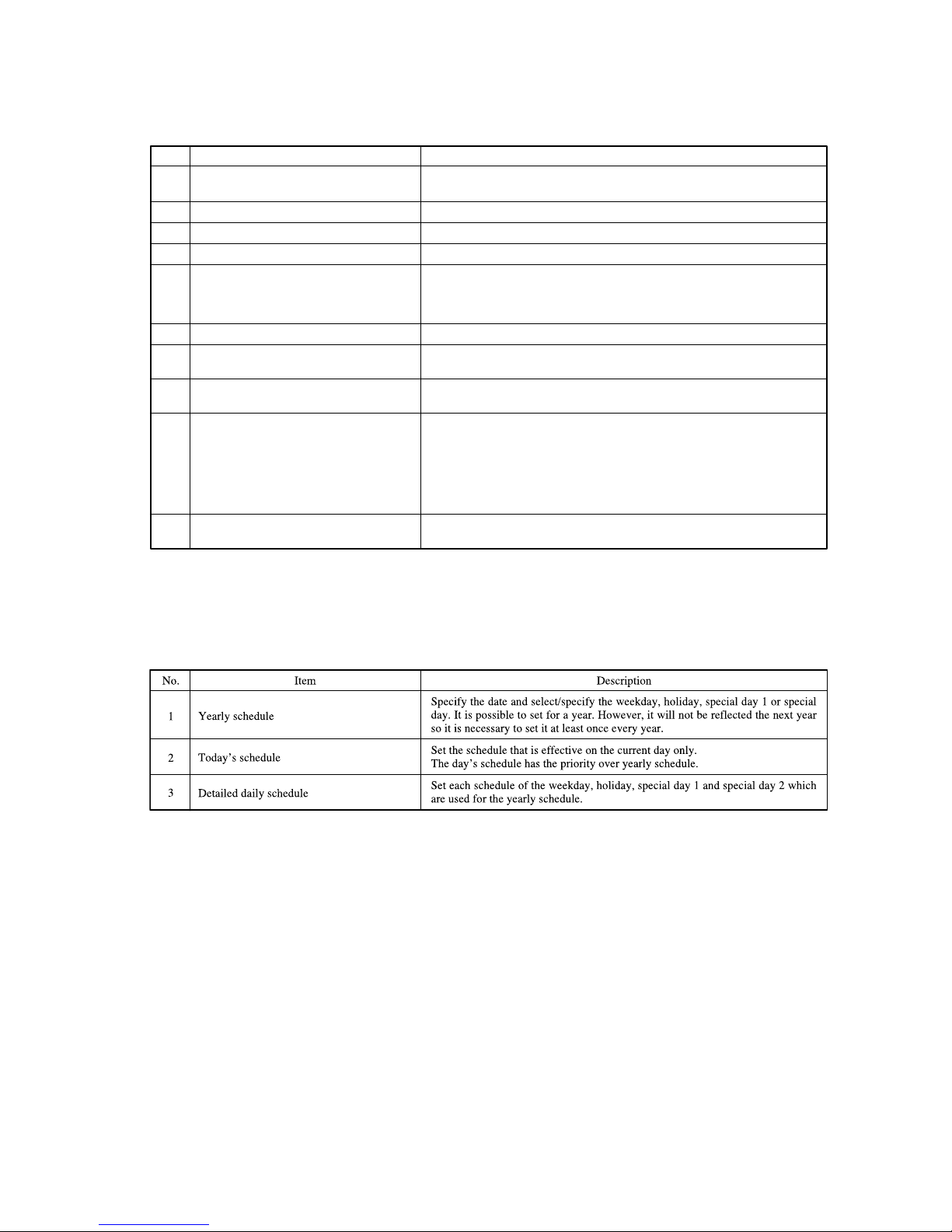
(5) Schedule setting
This schedule can be set by each group every one minute.
It is possible to register the RUN/STOP time, operation mode, remote controller Lock/Unlock setting, temperature setting at 16
times a day.(*)
(4) Status monitor
Status monitor can be applied in the unit of block, group or air-conditioner.
* When the operation time (GHP outdoor unit) exceeds 9,800 hours, it displays Inspection 2, or Inspection 1 if it exceeds 10,000 hours.
Item Description
RUN/STOP status
Operation mode
Temperature setting
Room temperature
Fan speed
Fan direction
Filter sign
No.
1
2
3
4
5
6
7
8
9
10
Displays the operation mode of the representative air-conditioner.
Displays the temperature setting of the representative air-conditioner.
Displays the suction temperature of the representative air-conditioner.
It displays “RUN” if any units are running or displays “STOP” if all units are
stopped.
When the filter cleaning time is exceeded on one or more indoor units, the filter sign
icon is turned on. When it corresponds to the unit No. on display, the icon blinks.
Displays the auto swing ON/OFF setting and position setting of the representative
air-conditioner.
When there is one or more indoor units requiring maintenance, the maitenance
icon is turned on. There are 4 types of operation of Inspection, Inspection 1, Inspection 2 and Backup.
Preference order of display is as shown below.
Backup > Inspection 1 > Inspection 2 > Inspection
It is possible to confirm on the “UNIT INFORMATION” screen which maintenance has been generated.
When any error is detected on one or more controlled indoor units, the error icon
is tumed on.
Maintenance
(*)
(Inspection, Inspection 1, Inspection 2 and
Backup)
Lock/Unlock setting of remote controller
Displays the status of permission/prohibition setting for remote controller of the
representative air-conditioner. Permission/prohibition setting for each function, as
set from the remote controller is not reflected because it is overwitten from SL3NAAE (SL3NA-BE).
Error
Displays the fan speed of
the representative
air-conditioner.
(*) e.q
①
7
:
50 RUN/STOP:RUN Lock/Unlock
:
–
Operation mode
:
Cool Set temp.:25
℃
②
9
:
40 RUN/STOP:STOP Lock/Unlock:ALL Lock Operation mode
:
–
Set temp.
:
–
③
10:00 RUN/STOP:RUN Lock/Unlock:ALL Unlock Operation mode
:
–
Set temp.
:
–
…
⑯
23
:
00 RUN/STOP:STOP Lock/Unlock:ALL Lock Operation mode
:
–
Set temp.
:
–
 Loading...