

Mitsubishi Heavy Industries SCM60ZM-S, SCM80ZM-S, SCM50ZM-S, SCM71ZM-S, SCM45ZM-S Technical Manual
...
TECHNICAL MANUAL
Manual No.'14•SCM-T-167
INVERTER MULTI-SPLIT SYSTEM
RESIDENTIAL AIR-CONDITIONERS
(Split system, air to air heat pump type)
(OUTDOOR UNIT)
SCM40ZM-S
45ZM-S
50ZM-S
60ZM-S
SCM71ZM-S
80ZM-S
100ZM-S
125ZM-S
(INDOOR UNIT)
Wall mounted type
SRK20ZMX-S
25ZMX-S
35ZMX-S
50ZMX-S
60ZMX-S
SRK20ZM-S
25ZM-S
35ZM-S
50ZM-S
SRK71ZM-S
Floor standing type
SRF25ZMX-S
35ZMX-S
50ZMX-S
4way ceiling cassette type
FDTC25VF
35VF
50VF
60VF
Ceiling concealed type
SRR25ZJ-S
35ZJ-S
50ZJ-S
60ZJ-S1
Ceiling suspended type
FDEN50VF
Duct connected Low/Middle static pressure type
FDUM50VF
updated November 27, 2014
-
1
-
'14 • SCM-T-167
CONTENTS
1. SPECIFICATIONS ......................................................................................... 2
2. EXTERIOR DIMENSIONS ............................................................................. 10
3. ELECTRICAL WIRINGS ............................................................................... 15
4. TECHNICAL INFORMATION ..................................................................... 20
(3) Model SCM50ZM-S
(1) Model SCM40ZM-S .............................................................................. 20
.............................................................................. 22
.............................................................................. 24
.............................................................................. 28
.............................................................................. 32
.............................................................................. 38
.............................................................................. 44
(2) Model SCM45ZM-S
(4) Model SCM60ZM-S
(5) Model SCM71ZM-S
(6) Model SCM80ZM-S
(7) Model SCM100ZM-S
Outdoor unit Regarding the outdoor unit
■Table of outdoor unit models
SCM40ZM-S SCM40ZJ-S
SCM45ZJ-S
SCM50ZJ-S1
SCM60ZJ-S1
SCM71ZJ-S1
SCM80ZJ-S1
SCM100ZJ-S1
SCM125ZJ-S1
SCM45ZM-S
SCM50ZM-S
SCM60ZM-S
SCM71ZM-S
SCM80ZM-S
SCM100ZM-S
SCM125ZM-S
This technical manual describes matters related to the outdoor units.
For any others and those related to the indoor units, refer to the Technical
Manual ’14 • SCM-T-150.
For applicable models, refer to the following comparison table.
-
2
-
'14 • SCM-T-167
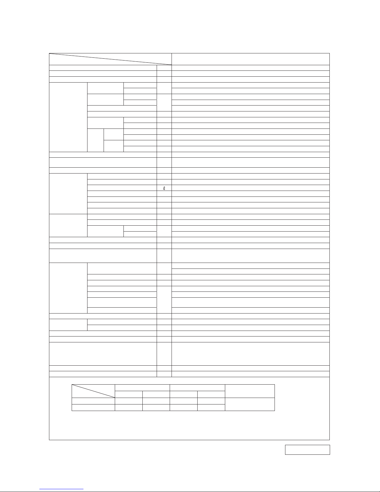
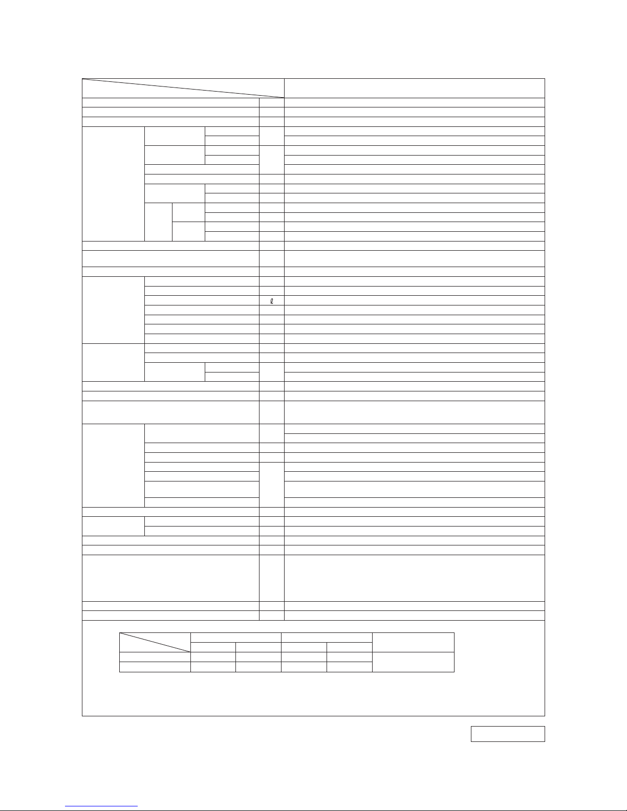
Model
Item
SCM40ZM-S
Cooling capacity (1) W 4000 (1800 (Min.)−5900 (Max.))
Heating capacity (1) W 4500 (1400 (Min.)−6900 (Max.))
Power source 1 Phase, 220−240 V, 50Hz
Operation
data (1)
Power
consumption
Cooling
kW
0.84 (0.49−1.90)
Heating 0.90 (0.47−2.30)
Running
current
Cooling
A
3.9 / 3.7 / 3.5 (220 / 230 / 240 V)
Heating 4.1 / 4.0 / 3.8 (220 / 230 / 240 V)
Inrush current 4.1 / 4.0 / 3.8 (220 / 230 / 240 V)
Max current (5) 14
COP
Cooling 4.76
Heating 5.00
Noise
level
Cooling
Sound level dB (A) 47
Power level dB 60
Heating
Sound level dB (A) 48
Power level dB 62
Exterior dimensions (Height x Width x Depth) mm 640 x 850 x 290
Exterior appearance
(Munsell color)
Stucco white
(4.2Y 7.5/1.1) near equivalent
Net weight kg 47
Refrigerant
equipment
Compressor type & Q'ty RM-T5113MDE2 (Twin rotary type) x 1
Motor (Starting method) kW 1.4 (Line starting)
Refrigerant oil
0.45 (DIAMOND FREEZE MA68)
Refrigerant (4) kg R410A 2 (Pre-Charged up to the piping length of 30m)
Heat exchanger M fins & inner grooved tubing
Refrigerant control Capillary tubes + Electronic expansion valve
Device control Microcomputer control
Air handling
equipment
Fan type & Q'ty Propeller fan x 1
Motor W 34
Air flow
Cooling
m
3
/min
40.0
Heating 40.0
Shock & vibration absorber Cushion rubber (for compressor)
Electric heater Crank case heater (220V 20W)
Safety devices
Compressor overheat protection, Overcurrent protection,
Frost protection, Serial signal error protection, Outdoor fan motor error protection,
Heating & Cooling overload protection
Installation
data
Refrigerant piping size (O.D) mm
Liquid line: φ6.35 (1/4") × 2
Gas line: φ9.52 (3/8") × 2
Connecting method Flare connecting
Insulation for piping Necessary (Both sides), independent
Length for one indoor unit
m
Max. 25
Total length for all rooms Max. 30
Vertical height difference between
outdoor unit and indoor unit
Max. 15 (Outdoor unit is higher)
Max. 15 (Outdoor unit is lower)
Height difference of the indoor units Max. 25
Recommended breaker size A 25
Connection wiring
Size x Core number 1.5mm
2
x 4 cores (Including earth cable)
Connecting method Terminal block (Screw fixing type)
IP number IPX4
Accessories (included) Installation sheet, Elbow, Grommet
Indoor unit to be combined
SRK20,25,35ZMX(A)-S
SRK20,25,35ZM(A)-S
SRF25,35ZMX(A)-S
SRR25,35ZJ-S
FDTC25,35VF
Number of connectable indoor units 2
Total of indoor units kW Max. 6
Note (1) The data are measured at the following conditions.
Item
Operation
Indoor air temperature Outdoor air temperature
Standards
DB WB DB WB
Cooling 27˚C 19˚C 35˚C 24˚C
ISO -T1 , J IS C 9 612
Heating 20˚C — 7˚C 6˚C
(2) This air-conditioner is manufactured and tested in conformity with the ISO.
(3) The operation data are applied to the 220/230/240V districts respectively.
(4) The refrigerant quantity to be charged includes the refrigerant in 30m connecting piping.
(Purging is not required even for the short piping.)
(5) Current value at maximum number of indoor units connected.
The pipe length for one indoor unit is 7.5m.
RWC 000 Z28 4
Adapted to RoHS directive
1. SPECIFICATIONS
-
3
-
'14 • SCM-T-167
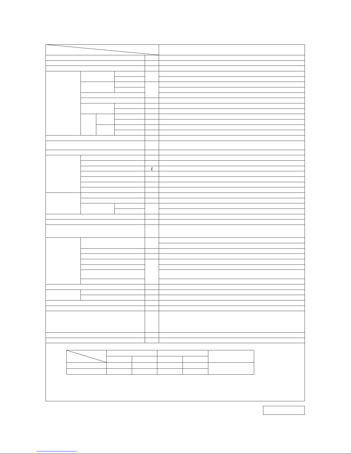
Model
Item
SCM45ZM-S
Cooling capacity (1) W 4500 (1800 (Min.)−6400 (Max.))
Heating capacity (1) W 5600 (1400 (Min.)−7400 (Max.))
Power source 1 Phase, 220−240 V, 50Hz
Operation
data (1)
Power
consumption
Cooling
kW
1.04 (0.49−2.14)
Heating 1.20 (0.47−2.57)
Running
current
Cooling
A
4.8 / 4.6 / 4.4 (220 / 230 / 240 V)
Heating 5.5 / 5.3 / 5.1 (220 / 230 / 240 V)
Inrush current 5.5 / 5.3 / 5.1 (220 / 230 / 240 V)
Max current (5) 14
COP
Cooling 4.33
Heating 4.67
Noise
level
Cooling
Sound level dB (A) 47
Power level dB 60
Heating
Sound level dB (A) 49
Power level dB 62
Exterior dimensions (Height x Width x Depth) mm 640 x 850 x 290
Exterior appearance
(Munsell color)
Stucco white
(4.2Y 7.5/1.1) near equivalent
Net weight kg 47
Refrigerant
equipment
Compressor type & Q'ty RM-T5113MDE2 (Twin rotary type) x 1
Motor (Starting method) kW 1.4 (Line starting)
Refrigerant oil
0.45 (DIAMOND FREEZE MA68)
Refrigerant (4) kg R410A 2 (Pre-Charged up to the piping length of 30m)
Heat exchanger M fins & inner grooved tubing
Refrigerant control Capillary tubes + Electronic expansion valve
Device control Microcomputer control
Air handling
equipment
Fan type & Q'ty Propeller fan x 1
Motor W 34
Air flow
Cooling
m
3
/min
40.0
Heating 40.0
Shock & vibration absorber Cushion rubber (for compressor)
Electric heater Crank case heater (220V 20W)
Safety devices
Compressor overheat protection, Overcurrent protection,
Frost protection, Serial signal error protection, Outdoor fan motor error protection,
Heating & Cooling overload protection
Installation
data
Refrigerant piping size (O.D) mm
Liquid line: φ6.35 (1/4") × 2
Gas line: φ9.52 (3/8") × 2
Connecting method Flare connecting
Insulation for piping Necessary (Both sides), independent
Length for one indoor unit
m
Max. 25
Total length for all rooms Max. 30
Vertical height difference between
outdoor unit and indoor unit
Max. 15 (Outdoor unit is higher)
Max. 15 (Outdoor unit is lower)
Height difference of the indoor units Max. 25
Recommended breaker size A 25
Connection wiring
Size x Core number 1.5mm
2
x 4 cores (Including earth cable)
Connecting method Terminal block (Screw fixing type)
IP number IPX4
Accessories (included) Installation sheet, Elbow, Grommet
Indoor unit to be combined
SRK20,25,35ZMX(A)-S
SRK20,25,35ZM(A)-S
SRF25,35ZMX(A)-S
SRR25,35ZJ-S
FDTC25,35VF
Number of connectable indoor units 2
Total of indoor units kW Max. 7
Note (1) The data are measured at the following conditions.
Item
Operation
Indoor air temperature Outdoor air temperature
Standards
DB WB DB WB
Cooling 27˚C 19˚C 35˚C 24˚C
ISO -T1 , J IS C 9 612
Heating 20˚C — 7˚C 6˚C
(2) This air-conditioner is manufactured and tested in conformity with the ISO.
(3) The operation data are applied to the 220/230/240V districts respectively.
(4) The refrigerant quantity to be charged includes the refrigerant in 30m connecting piping.
(Purging is not required even for the short piping.)
(5) Current value at maximum number of indoor units connected.
The pipe length for one indoor unit is 7.5m.
Adapted to RoHS directive
RWC 000 Z28 4
-
4
-
'14 • SCM-T-167
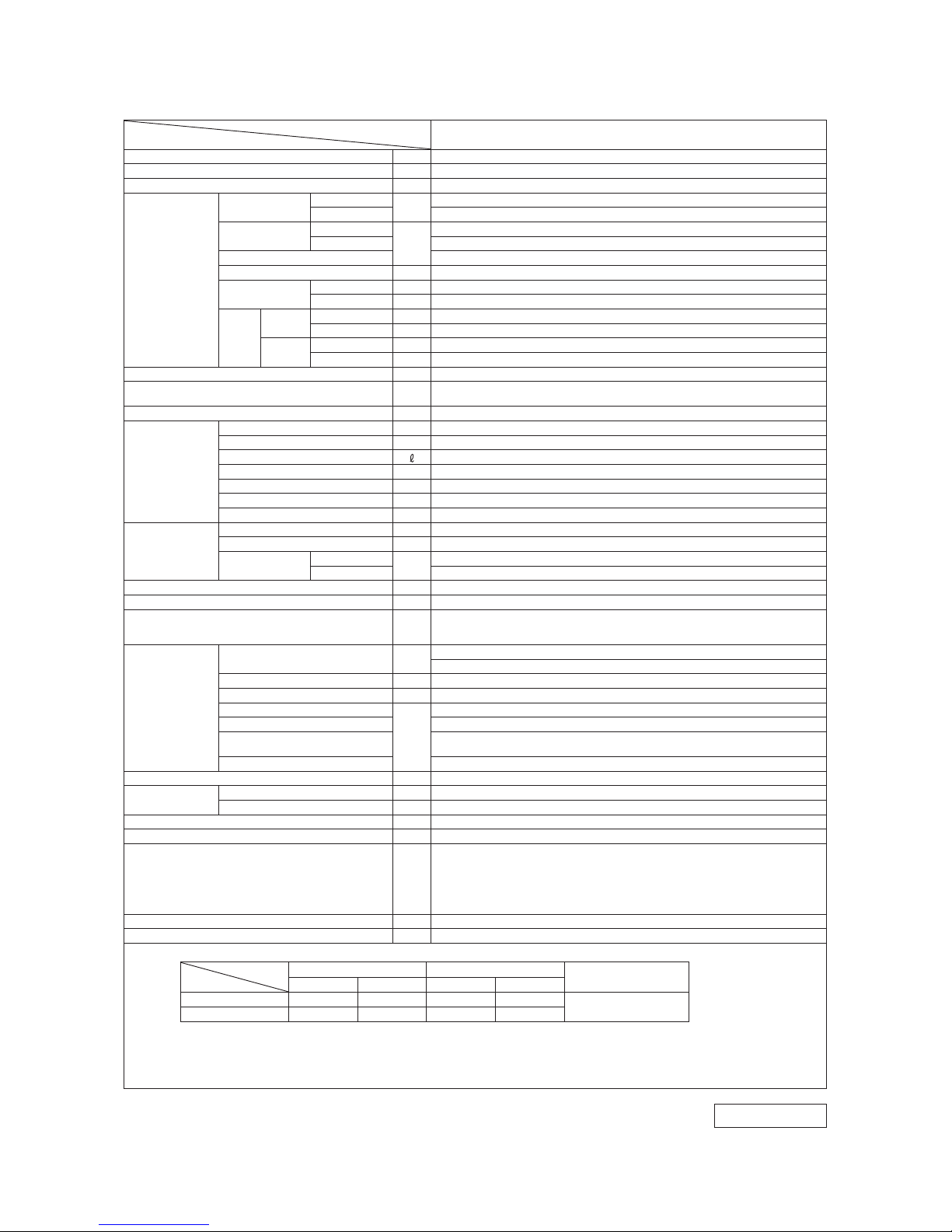
Model
Item
SCM50ZM-S
Cooling capacity (1) W 5000 (1800 (Min.)−7100 (Max.))
Heating capacity (1) W 6000 (1400 (Min.)−7500 (Max.))
Power source 1 Phase, 220−240 V, 50Hz
Operation
data (1)
Power
consumption
Cooling
kW
1.08 (0.50−2.15)
Heating 1.31 (0.48−2.58)
Running
current
Cooling
A
5.0 / 4.7 / 4.5 (220 / 230 / 240 V)
Heating 6.0 / 5.8 / 5.5 (220 / 230 / 240 V)
Inrush current 6.0 / 5.8 / 5.5 (220 / 230 / 240 V)
Max current (5) 15
COP
Cooling 4.63
Heating 4.58
Noise
level
Cooling
Sound level dB (A) 49
Power level dB 62
Heating
Sound level dB (A) 52
Power level dB 65
Exterior dimensions (Height x Width x Depth) mm 640 x 850 x 290
Exterior appearance
(Munsell color)
Stucco white
(4.2Y 7.5/1.1) near equivalent
Net weight kg 48
Refrigerant
equipment
Compressor type & Q'ty RM-T5113MDE2 (Twin rotary type) x 1
Motor (Starting method) kW 1.4 (Line starting)
Refrigerant oil
0.45 (DIAMOND FREEZE MA68)
Refrigerant (4) kg R410A 2.5 (Pre-Charged up to the piping length of 40m)
Heat exchanger M fins & inner grooved tubing
Refrigerant control Capillary tubes + Electronic expansion valve
Device control Microcomputer control
Air handling
equipment
Fan type & Q'ty Propeller fan x 1
Motor W 34
Air flow
Cooling
m
3
/min
41.0
Heating 41.0
Shock & vibration absorber Cushion rubber (for compressor)
Electric heater Crank case heater (220V 20W)
Safety devices
Compressor overheat protection, Overcurrent protection,
Frost protection, Serial signal error protection, Outdoor fan motor error protection,
Heating & Cooling overload protection
Installation
data
Refrigerant piping size (O.D) mm
Liquid line: φ6.35 (1/4") × 3
Gas line: φ9.52 (3/8") × 3
Connecting method Flare connecting
Insulation for piping Necessary (Both sides), independent
Length for one indoor unit
m
Max. 25
Total length for all rooms Max. 40
Vertical height difference between
outdoor unit and indoor unit
Max. 15 (Outdoor unit is higher)
Max. 15 (Outdoor unit is lower)
Height difference of the indoor units Max. 25
Recommended breaker size A 25
Connection wiring
Size x Core number 1.5mm
2
x 4 cores (Including earth cable)
Connecting method Terminal block (Screw fixing type)
IP number IPX4
Accessories (included) Union : (φ9.52扌φ12.7 ) × 1, Installation sheet, Elbow, Grommet
Indoor unit to be combined
SRK20,25,35,50ZMX(A)-S
SRK20,25,35,50ZM(A)-S
SRF25,35,50ZMX(A)-S
SRR25,35,50ZJ-S
FDTC25,35,50VF
FDEN50VF,FDUM50VF
Number of connectable indoor units Min. 2−Max. 3
Total of indoor units kW Max. 8.5
Note (1) The data are measured at the following conditions.
Item
Operation
Indoor air temperature Outdoor air temperature
Standards
DB WB DB WB
Cooling 27˚C 19˚C 35˚C 24˚C
ISO -T1 , J IS C 9 612
Heating 20˚C — 7˚C 6˚C
(2) This air-conditioner is manufactured and tested in conformity with the ISO.
(3) The operation data are applied to the 220/230/240V districts respectively.
(4) The refrigerant quantity to be charged includes the refrigerant in 40m connecting piping.
(Purging is not required even for the short piping.)
(5) Current value at maximum number of indoor units connected.
The pipe length for one indoor unit is 7.5m.
Adapted to RoHS directive
RWC 000 Z28 4

-
5
-
'14 • SCM-T-167
Note (1) The data are measured at the following conditions.
Item
Operation
Indoor air temperature Outdoor air temperature
Standards
DB WB DB WB
Cooling 27˚C 19˚C 35˚C 24˚C
ISO -T1 , J IS C 9 612
Heating 20˚C — 7˚C 6˚C
(2) This air-conditioner is manufactured and tested in conformity with the ISO.
(3) The operation data are applied to the 220/230/240V districts respectively.
(4) The refrigerant quantity to be charged includes the refrigerant in 40m connecting piping.
(Purging is not required even for the short piping.)
(5) Current value at maximum number of indoor units connected.
Model
Item
SCM60ZM-S
Cooling capacity (1) W 6000 (1800 (Min.)−7500 (Max.))
Heating capacity (1) W 6800 (1500 (Min.)−7800 (Max.))
Power source 1 Phase, 220−240 V, 50Hz
Operation
data (1)
Power
consumption
Cooling
kW
1.43 (0.50−2.39)
Heating 1.51 (0.60−3.00)
Running
current
Cooling
A
6.8 / 6.5 / 6.2 (220 / 230 / 240 V)
Heating 7.1 / 6.8 / 6.6 (220 / 230 / 240 V)
Inrush current 7.1 / 6.8 / 6.6 (220 / 230 / 240 V)
Max current (5) 17
COP
Cooling 4.2
Heating 4.5
Noise
level
Cooling
Sound level dB(A) 50
Power level dB 63
Heating
Sound level dB(A) 52
Power level dB 65
Exterior dimensions (Height x Width x Depth) mm 640 x 850 x 290
Exterior appearance
(Munsell color)
Stucco white
(4.2Y 7.5/1.1) near equivalent
Net weight kg 49
Refrigerant
equipment
Compressor type & Q'ty RM-T5118MDE2 (Twin rotary type) x 1
Motor (Starting method) kW 1.4 (Line starting)
Refrigerant oil
0.675 (DIAMOND FREEZE MA68)
Refrigerant (4) kg R410A 2.5 (Pre-Charged up to the piping length of 40m)
Heat exchanger M fins & inner grooved tubing
Refrigerant control Capillary tubes + Electronic expansion valve
Device control Microcomputer control
Air handling
equipment
Fan type & Q'ty Propeller fan x 1
Motor W 34
Air flow
Cooling
m
3
/min
42.0
Heating 42.0
Shock & vibration absorber Cushion rubber (for compressor)
Electric heater Crank case heater (220V 20W)
Safety devices
Compressor overheat protection, Overcurrent protection,
Frost protection, Serial signal error protection, Outdoor fan motor error protection,
Heating & Cooling overload protection
Installation
data
Refrigerant piping size (O.D) mm
Liquid line:φ6.35 (1/4") × 3
Gas line:φ9.52 (3/8") × 3
Connecting method Flare connecting
Insulation for piping Necessary (Both sides), independent
Length for one indoor unit
m
Max. 25
Total length for all rooms Max. 40
Vertical height difference between
outdoor unit and indoor unit
Max. 15 (Outdoor unit is higher)
Max. 15 (Outdoor unit is lower)
Height difference of the indoor units Max. 25
Recommended breaker size A 25
Connection wiring
Size x Core number 1.5mm
2
x 4 cores (Including earth cable)
Connecting method Terminal block (Screw fixing type)
IP number IPX4
Accessories (included) Union : (φ9.52扌φ12.7) × 2, Installation sheet, Elbow, Grommet
Indoor unit to be combined
SRK20,25,35,50,60ZMX(A)-S
SRK20,25,35,50ZM(A)-S
SRF25,35,50ZMX(A)-S
SRR25,35,50ZJ-S,60ZJ-S1
FDTC25,35,50,60VF
FDEN50VF,FDUM50VF
Number of connectable indoor units Min. 2−Max. 3
Total of indoor units kW Max. 11
Adapted to RoHS directive
The pipe length for one indoor unit is 7.5m.
RWC 000 Z28 4

-
6
-
'14 • SCM-T-167
Model
Item
SCM71ZM-S
Cooling capacity (1) W 7100 (1800 (Min.)−8800 (Max.))
Heating capacity (1) W 8600 (1500 (Min.)−9400 (Max.))
Power source 1 Phase, 220−240 V, 50Hz
Operation
data (1)
Power
consumption
Cooling
kW
1.74 (0.48−2.75)
Heating 2.00 (0.60−3.35)
Running
current
Cooling
A
8.0 / 7.6 / 7.3 (220 / 230 / 240 V)
Heating 9.2 / 8.8 / 8.4 (220 / 230 / 240 V)
Inrush current 9.2 / 8.8 / 8.4 (220 / 230 / 240 V)
Max current (5) 20
COP
Cooling 4.08
Heating 4.30
Noise
level
Cooling
Sound level dB (A) 52
Power level dB 65
Heating
Sound level dB (A) 54
Power level dB 66
Exterior dimensions (Height x Width x Depth) mm 750 x 880 x 340
Exterior appearance
(Munsell color)
Stucco white
(4.2Y 7.5/1.1) near equivalent
Net weight kg 62
Refrigerant
equipment
Compressor type & Q'ty RM-T5118MDE2 (Twin rotary type) x 1
Motor (Starting method) kW 1.4 (Line starting)
Refrigerant oil
0.675 (DIAMOND FREEZE MA68)
Refrigerant (4) kg R410A 3.15 (Pre-Charged up to the piping length of 40m)
Heat exchanger M fins & inner grooved tubing
Refrigerant control Capillary tubes + Electronic expansion valve
Device control Microcomputer control
Air handling
equipment
Fan type & Q'ty Propeller fan x 1
Motor W 86
Air flow
Cooling
m
3
/min
56.0
Heating 56.0
Shock & vibration absorber Cushion rubber (for compressor)
Electric heater Crank case heater (220V 20W)
Safety devices
Compressor overheat protection, Overcurrent protection,
Frost protection, Serial signal error protection, Outdoor fan motor error protection,
Heating & Cooling overload protection
Installation
data
Refrigerant piping size (O.D) mm
Liquid line: φ6.35 (1/4") × 4
Gas line: φ9.52 (3/8") × 4
Connecting method Flare connecting
Insulation for piping Necessary (Both sides), independent
Length for one indoor unit
m
Max. 25
Total length for all rooms Max. 70
Vertical height difference between
outdoor unit and indoor unit
Max. 20 (Outdoor unit is higher)
Max. 20 (Outdoor unit is lower)
Height difference of the indoor units Max. 25
Recommended breaker size A 25
Connection wiring
Size x Core number 1.5mm
2
x 4 cores (Including earth cable)
Connecting method Terminal block (Screw fixing type)
IP number IPX4
Accessories (included) Union : (φ9.52扌φ12.7) × 2, Installation sheet, Elbow, Grommet × 2
Indoor unit to be combined
SRK20,25,35,50,60ZMX(A)-S
SRK20,25,35,50ZM(A)-S
SRF25,35,50ZMX(A)-S
SRR25,35,50ZJ-S,60ZJ-S1
FDTC25,35,50,60VF
FDEN50VF,FDUM50VF
Number of connectable indoor units Min. 2−Max. 4
Total of indoor units kW Max. 12.5
Note (1) The data are measured at the following conditions.
Item
Operation
Indoor air temperature Outdoor air temperature
Standards
DB WB DB WB
Cooling 27˚C 19˚C 35˚C 24˚C
ISO -T1 , J IS C 9 612
Heating 20˚C — 7˚C 6˚C
(2) This air-conditioner is manufactured and tested in conformity with the ISO.
(3) The operation data are applied to the 220/230/240V districts respectively.
(4) The refrigerant quantity to be charged includes the refrigerant in 40m connecting piping.
(Purging is not required even for the short piping.)
(5) Current value at maximum number of indoor units connected.
The pipe length for one indoor unit is 7.5m.
Adapted to RoHS directive
RWC 000 Z28 4
-
7
-
'14 • SCM-T-167
Model
Item
SCM80ZM-S
Cooling capacity (1) W 8000 (1800 (Min.)−9200 (Max.))
Heating capacity (1) W 9300 (1500 (Min.)−9800 (Max.))
Power source 1 Phase, 220−240 V, 50Hz
Operation
data (1)
Power
consumption
Cooling
kW
2.16 (0.48−2.83)
Heating 2.26 (0.60−3.43)
Running
current
Cooling
A
9.9 / 9.4 / 9.0 (220 / 230 / 240 V)
Heating 10.4 / 10.0 / 9.5 (220 / 230 / 240 V)
Inrush current 10.4 / 10.0 / 9.5 (220 / 230 / 240 V)
Max current (5) 20
COP
Cooling 3.70
Heating 4.12
Noise
level
Cooling
Sound level dB(A) 54
Power level dB 66
Heating
Sound level dB(A) 54
Power level dB 66
Exterior dimensions (Height x Width x Depth) mm 750 x 880 x 340
Exterior appearance
(Munsell color)
Stucco white
(4.2Y 7.5/1.1) near equivalent
Net weight kg 62
Refrigerant
equipment
Compressor type & Q'ty RM-T5118MDE2 (Twin rotary type) x 1
Motor (Starting method) kW 1.4 (Line starting)
Refrigerant oil
0.675 (DIAMOND FREEZE MA68)
Refrigerant (4) kg R410A 3.15 (Pre-Charged up to the piping length of 40m)
Heat exchanger M fins & inner grooved tubing
Refrigerant control Capillary tubes + Electronic expansion valve
Device control Microcomputer control
Air handling
equipment
Fan type & Q'ty Propeller fan x 1
Motor W 86
Air flow
Cooling
m
3
/min
56.0
Heating 56.0
Shock & vibration absorber Cushion rubber (for compressor)
Electric heater Crank case heater (220V 20W)
Safety devices
Compressor overheat protection, Overcurrent protection,
Frost protection, Serial signal error protection, Outdoor fan motor error protection,
Heating & Cooling overload protection
Installation
data
Refrigerant piping size (O.D) mm
Liquid line:φ6.35 (1/4") × 4
Gas line:φ9.52 ( 3/8") × 4
Connecting method Flare connecting
Insulation for piping Necessary (Both sides), independent
Length for one indoor unit
m
Max. 25
Total length for all rooms Max. 70
Vertical height difference between
outdoor unit and indoor unit
Max. 20 (Outdoor unit is higher)
Max. 20 (Outdoor unit is lower)
Height difference of the indoor units Max. 25
Recommended breaker size A 25
Connection wiring
Size x Core number 1.5mm
2
x 4 cores (Including earth cable)
Connecting method Terminal block (Screw fixing type)
IP number IPX4
Accessories (included) Union : (φ9.52扌φ12.7) × 2, Installation sheet, Elbow, Grommet × 2
Indoor unit to be combined
SRK20,25,35,50,60ZMX(A)-S
SRK20,25,35,50ZM(A)-S
SRF25,35,50ZMX(A)-S
SRR25,35,50ZJ-S,60ZJ-S1
FDTC25,35,50,60VF
FDEN50VF,FDUM50VF
Number of connectable indoor units Min. 2−Max. 4
Total of indoor units kW Max. 13.5
Note (1) The data are measured at the following conditions.
Item
Operation
Indoor air temperature Outdoor air temperature
Standards
DB WB DB WB
Cooling 27˚C 19˚C 35˚C 24˚C
ISO -T1 , J IS C 9 612
Heating 20˚C — 7˚C 6˚C
(2) This air-conditioner is manufactured and tested in conformity with the ISO.
(3) The operation data are applied to the 220/230/240V districts respectively.
(4) The refrigerant quantity to be charged includes the refrigerant in 40m connecting piping.
(Purging is not required even for the short piping.)
(5) Current value at maximum number of indoor units connected.
The pipe length for one indoor unit is 7.5m.
Adapted to RoHS directive
RWC 000 Z28 4

-
8
-
'14 • SCM-T-167
Model
Item
SCM100ZM-S
Cooling capacity (1) W 10000 (1800 (Min.)−12000 (Max.))
Heating capacity (1) W 12000 (1500 (Min.)−13500 (Max.))
Power source 1 Phase, 220−240 V, 50Hz
Operation
data (1)
Power
consumption
Cooling
kW
2.86 (0.65−4.03)
Heating 2.93 (0.70−3.40)
Running
current
Cooling
A
13.0 / 12.4 / 11.9 (220 / 230 / 240 V)
Heating 13.3 / 12.8 / 12.2 (220 / 230 / 240 V)
Inrush current 13.3 / 12.8 / 12.2 (220 / 230 / 240 V)
Max current (6) 28
COP
Cooling 3.50
Heating 4.10
Noise
level
Cooling
Sound level dB (A) 56
Power level dB 68
Heating
Sound level dB (A) 59
Power level dB 71
Exterior dimensions (Height x Width x Depth) mm 945 x 970 x 370
Exterior appearance
(Munsell color)
Stucco white
(4.2Y 7.5/1.1) near equivalent
Net weight kg 92
Refrigerant
equipment
Compressor type & Q'ty RM-T5126MDE21 (Twin rotary type) x 1
Motor (Starting method) kW 4.0 (Line starting)
Refrigerant oil
1.0 (DIAMOND FREEZE MA68)
Refrigerant (4) kg R410A 6.00 (Pre-Charged up to the piping length of 50m)
Heat exchanger M fins & inner grooved tubing
Refrigerant control Capillary tubes + Electronic expansion valve
Device control Microcomputer control
Air handling
equipment
Fan type & Q'ty Propeller fan x 1
Motor W 86
Air flow
Cooling
m
3
/min
75.0
Heating 75.0
Shock & vibration absorber Cushion rubber (for compressor)
Electric heater Crank case heater (220V 20W)
Safety devices
Compressor overheat protection, Overcurrent protection,
Frost protection, Serial signal error protection, Outdoor fan motor error protection,
Heating & Cooling overload protection
Installation
data
Refrigerant piping size (O.D) mm
Liquid line: φ6.35 (1/4") × 5
Gas line: φ9.52 (3/8") × 5
Connecting method Flare connecting
Insulation for piping Necessary (Both sides), independent
Length for one indoor unit
m
Max. 25
Total length for all rooms Max. 90
Vertical height difference between
outdoor unit and indoor unit
Max. 20 (Outdoor unit is higher)
Max. 20 (Outdoor unit is lower)
Height difference of the indoor units Max. 25
Recommended breaker size A 30
Connection wiring
Size x Core number 1.5mm
2
x 4 cores (Including earth cable)
Connecting method Terminal block (Screw fixing type)
IP number IPX4
Accessories (included) Union, Installation sheet, Elbow, Grommet × 2
Indoor unit to be combined
SRK20,25,35,50,60ZMX(A)-S,SRK20,25,35,50,71ZM(A)-S
SRF25,35,50ZMX(A)-S
SRR25,35,50ZJ-S,60ZJ-S1
FDTC25,35,50,60VF
FDEN50VF,FDUM50VF
Number of connectable indoor units Min. 2−Max. 5 (5)
Total of indoor units kW Max. 16.0
Note (1) The data are measured at the following conditions.
Item
Operation
Indoorairtemperature Outdoorairtemperature
Standards
DB WB DB WB
Cooling 27˚C 19˚C 35˚C 24˚C
ISO-T1,JISC 961 2
Heating 20˚C 7 ˚C 6˚C
(2)Thisair-conditionerismanufacturedandtestedinconformitywiththeISO.
(3)Theoperationdataareappliedtothe220/230/240Vdistrictsrespectively.
(4)Therefrigerantquantitytobechargedincludestherefrigerantin50mconnectingpiping.
(Purgingisnotrequiredevenfortheshortpiping.)
(5)IncaseofcombinationwithSRK-ZMX-S,SRK71ZM-S,FDEN50VFonly3indoorunitscanbeconnectable.
IncaseofSRK71ZM-S+SRK71ZM-S,2indoorunitscanbeconnectable.
(6)Currentvalueatmaximumnumberofindoorunitsconnected.
Thepipelengthforoneindoorunitis7.5m.
AdaptedtoRoHS directive
RWC 000 Z28 4
#

-
9
-
'14 • SCM-T-167
Model
Item
SCM125ZM-S
Cooling capacity (1) W 12500 (1800 (Min.)−14000 (Max.))
Heating capacity (1) W 13500 (1500 (Min.)−14000 (Max.))
Power source 1 Phase, 220−240 V, 50Hz
Operation
data (1)
Power
consumption
Cooling
kW
3.90 (0.65−4.80)
Heating 3.25 (0.70−3.42)
Running
current
Cooling
A
17.7 / 17.0 / 16.3 (220 / 230 / 240 V)
Heating 14.8 / 14.1 / 13.6 (220 / 230 / 240 V)
Inrush current 17.7 / 17.0 / 16.3 (220 / 230 / 240 V)
Max current (6) 29
COP
Cooling 3.21
Heating 4.15
Noise
level
Cooling
Sound level dB (A) 57
Power level dB 69
Heating
Sound level dB (A) 60
Power level dB 72
Exterior dimensions (Height x Width x Depth) mm 945 x 970 x 370
Exterior appearance
(Munsell color)
Stucco white
(4.2Y 7.5/1.1) near equivalent
Net weight kg 92
Refrigerant
equipment
Compressor type & Q'ty RM-T5126MDE21 (Twin rotary type) x 1
Motor (Starting method) kW 4.0 (Line starting)
Refrigerant oil
1.0 (DIAMOND FREEZE MA68)
Refrigerant (4) kg R410A 6.00 (Pre-Charged up to the piping length of 50m)
Heat exchanger M fins & inner grooved tubing
Refrigerant control Capillary tubes + Electronic expansion valve
Device control Microcomputer control
Air handling
equipment
Fan type & Q'ty Propeller fan x 1
Motor W 86
Air flow
Cooling
m
3
/min
75.0
Heating 82.0
Shock & vibration absorber Cushion rubber (for compressor)
Electric heater Crank case heater (220V 20W)
Safety devices
Compressor overheat protection, Overcurrent protection,
Frost protection, Serial signal error protection, Outdoor fan motor error protection,
Heating & Cooling overload protection
Installation
data
Refrigerant piping size (O.D) mm
Liquid line: φ6.35 (1/4") × 6
Gas line: φ9.52 (3/8") × 6
Connecting method Flare connecting
Insulation for piping Necessary (Both sides), independent
Length for one indoor unit
m
Max. 25
Total length for all rooms Max. 90
Vertical height difference between
outdoor unit and indoor unit
Max. 20 (Outdoor unit is higher)
Max. 20 (Outdoor unit is lower)
Height difference of the indoor units Max. 25
Recommended breaker size A 30
Connection wiring
Size x Core number 1.5mm
2
x 4 cores (Including earth cable)
Connecting method Terminal block (Screw fixing type)
IP number IPX4
Accessories (included) Union, Installation sheet, Elbow, Grommet × 2
Indoor unit to be combined
SRK20,25,35,50,60ZMX(A)-S,SRK20,25,35,50,71ZM(A)-S
SRF25,35,50ZMX(A)-S
SRR25,35,50ZJ-S,60ZJ-S1
FDTC25,35,50,60VF
FDEN50VF,FDUM50VF
Number of connectable indoor units Min. 2−Max. 6 (5)
Total of indoor units kW Max. 19.5
Note (1) The data are measured at the following conditions.
Item
Operation
Indoorairtemperature Outdoorairtemperature
Standards
DB WB DB WB
Cooling 27˚C 19˚C 35˚C 24˚C
ISO-T1,JISC 961 2
Heating 20˚C 7 ˚C 6˚C
(2)Thisair-conditionerismanufacturedandtestedinconformitywiththeISO.
(3)Theoperationdataareappliedtothe220/230/240Vdistrictsrespectively.
(4)Therefrigerantquantitytobechargedincludestherefrigerantin50mconnectingpiping.
(Purgingisnotrequiredevenfortheshortpiping.)
(5)IncaseofcombinationwithSRK-ZMX-S,SRK71ZM-S,FDEN50VFonly,3indoorunitscanbeconnectable.
IncaseofSRK71ZM-S+SRK71ZM-S,2indoorunitscanbeconnectable.
(6)Currentvalueatmaximumnumberofindoorunitsconnected.
Thepipelengthforoneindoorunitis7.5m.
AdaptedtoRoHS directive
RWC 000 Z28 4
#

-
10
-
'14 • SCM-T-167
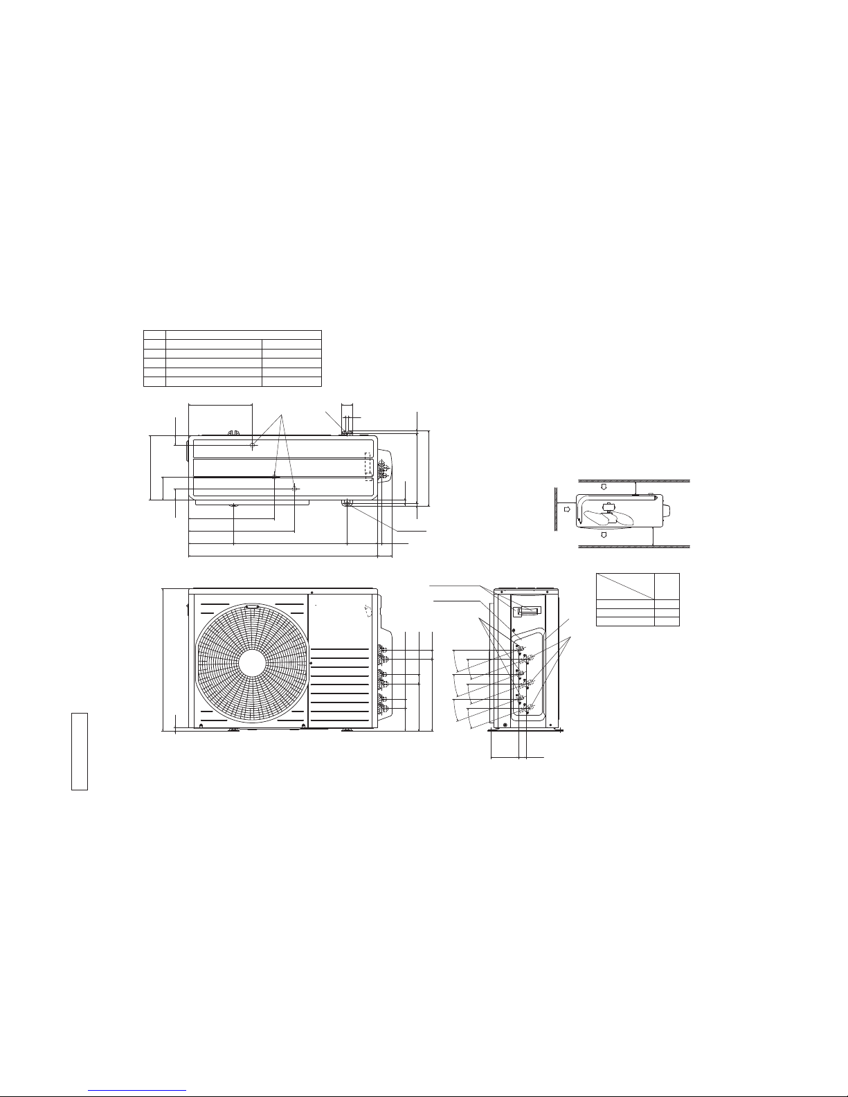
2. EXTERIOR DIMENSIONS
Models SCM40ZM-S, 45ZM-S
Unit:mm
43.5
286.4
49.6
290
476
203.1 510 136.9
14 312.5
50
12
13.5
340
640
15
850
100.3 42.7
124.1 34.6
2-16x12
211 42.7
20°
20°
20°
20°
103.2
385.9
14.6
17.9
65
Symbol Content
A Service valve connection(gas side) φ9.52(3/8")(Flare)
B Service valve connection(liquid side) φ6.35(1/4")(Flare)
C Pipe/cable draw-out hole
D Drain discharge hole φ20 x 3 places
E Anchor bolt hole M10 x 4 places
Service panel
Terminal block
L1
L3
Intake
No obstacles
(Service space
L2
Intake
Outlet
Note
(1)It must not be surrounded by walls on four sides.
(2)The unit must be fixed with anchor bolts. An anchor bolt
must not protrude more than 15mm.
(3)Where the unit is subjected to strong winds, lay it in such a
direction that the blower outlet faces perpendicularly to the
dominant wind direction.
(4)Leave 1.2m or more space above the unit.
(5)A wall in front of the blower outlet must not exceed the
unit's height.
(6)The model name label is attached on the service panel.
100
600
L2
L3
L1
Examples of
100
Installation
Dimensions
Minimum installation space
for electrical
parts)
D
B
A
C
E
RW C0 00 Z28 0
-
11
-
'14 • SCM-T-167
Models SCM50ZM-S, 60ZM-S
Unit:mm
43.5
286.4
49.6
136.9
14 312.5
50
12
13.5
340
640
15
100.3 42.7
124.1 34.6
211 42.7
20°
20°
20°
20°
321.7 42.7
20°
20°
290
476
203.1 510
850
103.2
385.9
14.6
2-16x12
17.9
65
Symbol Content
A Service valve connection(gas side)
φ
9.52(3/8")(Flare)
B Service valve connection(liquid side)
φ
6.35(1/4")(Flare)
C Pipe/cable draw-out hole
D Drain discharge hole
φ
20 x 3 places
E Anchor bolt hole M10 x 4 places
Service panel
Terminal block
L1
L3
Intake
L2
Intake
Outlet
Note
(1)It must not be surrounded by walls on four sides.
(2)The unit must be fixed with anchor bolts. An anchor bolt
must not protrude more than 15mm.
(3)Where the unit is subjected to strong winds, lay it in such a
direction that the blower outlet faces perpendicularly to the
dominant wind direction.
(4)Leave 1.2m or more space above the unit.
(5)A wall in front of the blower outlet must not exceed the
unit's height.
(6)The model name label is attached on the service panel.
100
600
L2
L3
L1
Examples of
100
Installation
Dimensions
Minimum installation space
No obstacles
(Service space
for electrical
parts)
D
B
A
C
E
RW C0 00 Z28 1

-
12
-
'14 • SCM-T-167
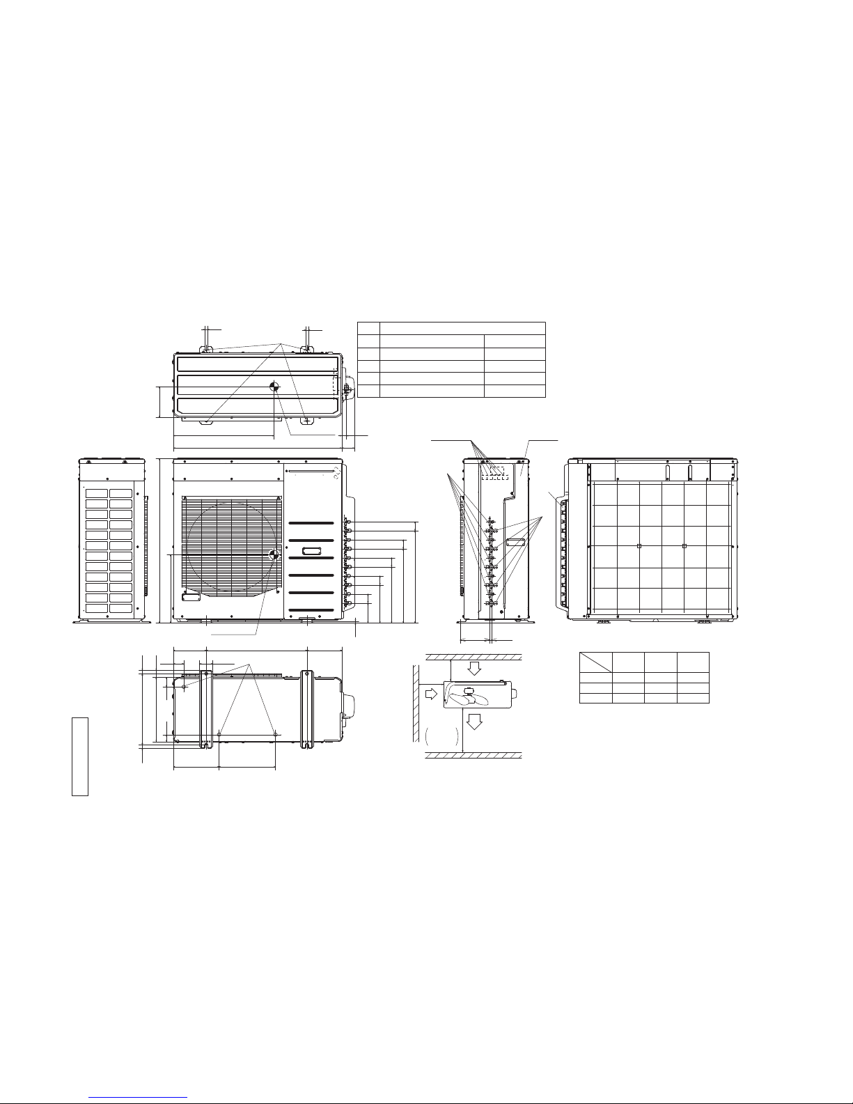
Models SCM71ZM-S, 80ZM-S
Unit:mm
L1
L3
Intake
L2
Intake
Outlet
Notes
(1)It must not be surrounded by walls on four sides.
(2)The unit must be fixed with anchor bolts. An anchor bolt
must not protrude more than 15mm.
(3)Where the unit is subjected to strong winds, lay it in such a
direction that the blower outlet faces perpendicularly to the
dominant wind direction.
(4)Leave 1.2m or more space above the unit.
(5)A wall in front of the blower outlet must not exceed the
unit's height.
(6)The model name label is attached on the rear panel.
100
600
L2
L3
L1
Examples of
100
Installation
Dimensions
Minimum installation space
Terminal block
Symbol Content
A Service valve connection(gas side) φ9.52(3/8")(Flare)
B Service valve connection(liquid side) φ6.35(1/4")(Flare)
C Pipe/cable draw-out hole
D Drain discharge hole φ20 x 3 places
E Anchor bolt hole M10 x 4 places
No obstacles
(Service space
for electrical
parts)
15
60
38019
418
73880
150 580 150 26
340
2-R7.5
223
47.5
310
61
61
110.4 52
185 10
24
750
214.4 52
318.4 52
422.4 52
20
D
C
E
B
A
RW C0 00 Z27 7
-
13
-
'14 • SCM-T-167
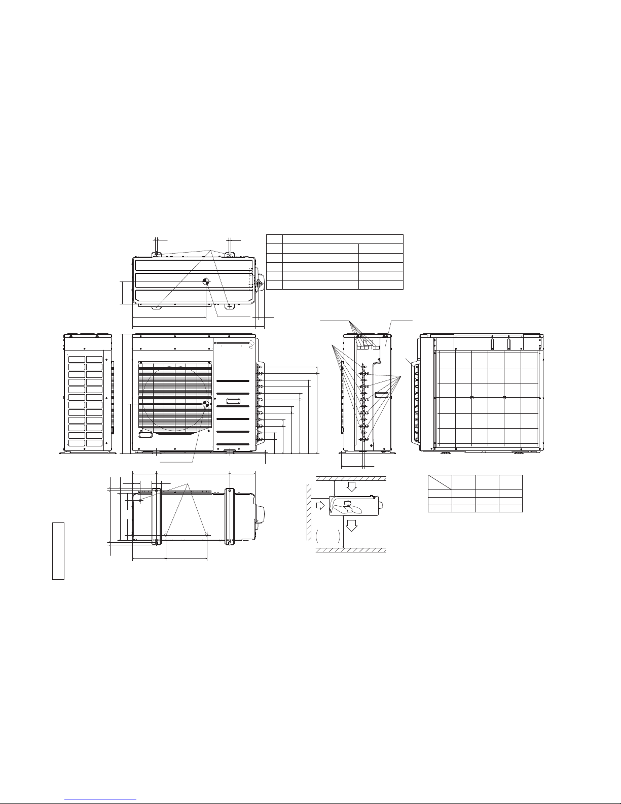
Model SCM100ZM-S
L1
L3
Intake
Outlet
Intake
Minimum installation space
space
Service
Notes
(1) It must not be surrounded by walls on the four sides.
(2)The unit must be fixed with anchor bolts. An anchor bolt must not
protrude more than 15mm.
(3) Where the unit is subject to strong winds, lay it in such
a direction that the blower outlet faces perpendicularly
to the dominant wind direction.
(4) Leave 1m or more space above the unit.
(5) A wall in front of the blower outlet must not exceed the units height.
(6)The model name label is attached on the rear panel.
φ
9.52(3/8")(Flare)
Content
C Pipe/cable draw-out hole
D
E Anchor bolt hole
Drain discharge hole
Symbol
B
A Service valve connection(gas side)
M10×4places
φ
20×3places
Service valve connection(liquid side)
φ
6.35(1/4")(Flare)
L2
L3
L1
300
150
Open
I Ⅱ
Open
150
500
Ⅲ
Open
300
5
Unit:mm
Examples of
Dimensions
installation
L2
No obstacles
(Service space
for electrical
parts)
580
76
190
60
55
20
200
262.8 325
945
410
40370
40
20
52115.2
219.2 52
52
52
52531.2
427.2
323.2
26
970
10170
15
15
580
177
393
10
73
Terminal block
Center of gravity
Center of gravity
Rear panel
B
A
C
E
D
RW C0 00 Z27 8
-
14
-
'14 • SCM-T-167
Model SCM125ZM-S
RW C0 00 Z27 9
B
A
C
E
D
L1
L3
Intake
Outlet
Intake
Minimum installation space
space
Service
Notes
(1) It must not be surrounded by walls on the four sides.
(2)The unit must be fixed with anchor bolts. An anchor bolt must not
protrude more than 15mm.
(3) Where the unit is subject to strong winds, lay it in such
a direction that the blower outlet faces perpendicularly
to the dominant wind direction.
(4) Leave 1m or more space above the unit.
(5) A wall in front of the blower outlet must not exceed the units height.
(6)The model name label is attached on the rear panel.
φ
9.52(3/8")(Flare)
Content
C Pipe/cable draw-out hole
D
E Anchor bolt hole
Drain discharge hole
Symbol
B
A Service valve connection(gas side)
M10×4places
φ
20×3places
Service valve connection(liquid side)
φ
6.35(1/4")(Flare)
L2
L3
L1
300
150
Open
I Ⅱ
Open
150
500
Ⅲ
Open
300
5
Unit:mm
Examples of
Dimensions
installation
L2
No obstacles
(Service space
for electrical
parts)
580
76
190
60
55
20
200
262.8 325
945
410
40370
40
20
52115.2
219.2 52
52
52
52531.2
427.2
323.2
26
970
10170
15
52635.2
15
580
177
393
10
73
Terminal block
Center of gravity
Center of gravity
Rear panel
-
15
-
'14 • SCM-T-167
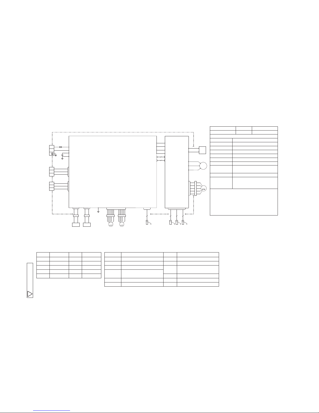
3. ELECTRICAL WIRINGS
Models SCM40ZM-S, 45ZM-S
Color Marks
Mark Color Mark Color Item
Meaning of Marks
Description Item Description
BKBRBlack
Brown
RD Y/GRed Yellow/Green
WH White
OR Orange
CNA-CN20S
EEV A,EEV B
R
Compressor motor
Electric expansion valve
(coil)
Reactor
Tho-A
Tho-D
Heat exchanger sensor
Outdoor air temp. sensor
Discharge pipe temp. sensor
CM
Tho-R
Connector
20S 4 Way valve(coil)
Suction pipe temp. sensor
Tho-S
FMo Fan motor
Terminal blockTB1-TB3
(outdoor unit)
HEATER Crank case heater
FunctionColorIndication lamp
Warning lampRedLED e (1)
Self diagnosis function by led e
1-Time flash Current cut
2-Time flash Trouble of outdoor unit
3-Time flash Over current
4-Time flash Transmission error
5-Time flash Over heat of compressor
6-Time flash Error of signal transmission
7-Time flash Lock of compressor
8-Time flash Sensor error
(Except discharge pipe sensor)
Four sec light
and Discharge pipe sensor error
four sec off
Caution ・When the compressor does not run Immediately after
hitting on the button,wait for 5 to 10 minutes.(There is
possibility of delayed start.)
・High voltage is produced in the control box. don't touch
electrical parts in the control box for 5 minutes after
cutting power source.
Light on Outdoor fan motor error
EEV
S
BK
WH
RD
V
W
U
FM0
CM
R
CNTH
CNFAN
S-2
BK
WH
WH
S-1
CNSUB
CNMAIN
S
R
BK
WH
IN
IN
S
R
O
O
250V 15A
FUSE
CN20S
G2
Y/G
C-2
RD
C-1
CN20V
CN20V
5
2
G1
Y/G
G
Y/G
CNEEV1
CNTH
TB2
CNA
CNB
TB1
N
L
A
EEV
B
Y/G
WH
BK
UNIT A
UNIT B
M
3~
M
M
M
Power source
1 Phase
AC 220−240V
50Hz
WH
RD
PCB 2(SUB)
PCB 1(MAIN)
20S
HEATER
WH
RD
CNHEAT
T2
T1
R
OR
YE
3
2
1
BK
WH
RD
3
2
1
BK
WH
BR
TB3
2 2 2
t゜
t゜
t゜
t゜
2
Tho-S
Tho-R Tho-A Tho-D
YE Yellow
A
RWC000Z2 32
 Loading...