

Mitsubishi Heavy Industries S6S, S4S Service Manual

1 / 170
Service Manual Mitsubishi SS-Series diesel engines
Version 08/2004
ENGLISH
FOREWORD
This service manual is written to familiarize you with the maintenance of your S4S and S6S Diesel Engine. If the
engine is carefully maintained it will deliver a long productive life and efficient performance marked by power and
economy.
Before you attempt to inspect, disassemble, or repair the engine, read this manual carefully to learn more about the
engine and how to care for it properly. All descriptions, illustrations, specifications and serial numbers in this manual
are effective as of the date printing of this manual.
The information contained in this manual applies to the engine model produced at the time of publication.
It should be noted that specifications and design may change due to improvements made thereafter.
For items other than those in this publication, refer to the operation manual for a unit on which the engine is
mounted.
Service Manual
Mitsubishi SS-Series diesel engines
Version 08/2004
Copyright © 2004 MHI Equipment Europe B.V.
2 / 170
Service Manual Mitsubishi SS-Series diesel engines
Version 08/2004
ENGLISH
How to use this manual
1. Parts in illustrations are numbered to correspond with references to these numbers in text.
2. Items or conditions to be inspected during disassembly are enclosed in a box in the disassembled views:
3. Maintenance standards for inspection and repair are described in text where they are relevant. For a quick
summary of maintenance standards refer to group 2 of this manual.
4. The sequence in which parts are to be reassembled is summarized below each assembled view. Such as:
5
2 4 3 1
5. Tightening torque under wet conditions is indicated as “(wet)” in text, drawings, and tables. When so indicated
as (wet), apply engine oil to the threaded portion of the fastener. Unless indicated as such, the tightening torque
is to be assumed in the dry condition.
6. Pay attention to the special notes, cautions and warnings.
Notes, Cautions, Warnings, Dangers
Notes, cautions, warnings, dangers are used in this manual to emphasize important or critical instructions or advice.
Terms Used in This Manual
Before you read this manual, note that the following special terms are used in dimensional and other specifications.
Assembly Standard Indicates the dimension of a part, the dimension to be attained at the time of reassembly
or the standard performance. The value is rounded to the nearest whole number needed
for inspection and is different from the design value.
Nominal Value Indicates the standard dimension of a part.
Repair Limit A part which has reached this limit must be repaired.
Service Limit A part which has reached this limit must be replaced.
Standard Clearance Indicates the clearance to be obtained between mating parts at reassembly.
Clogged oil hole
DANGER
Indicates the most serious specific potential hazard resulting in serious bodily
injury or death.
WARNING
Indicates a specific potential hazard resulting in bodily injury.
CAUTION
Indicates operating procedure, practice, etc., resulting in personal injury or
damage to or destruction of engine.
NOTE
An operating procedure, condition, etc. that will help you work more efficiently.

3 / 170
Service Manual Mitsubishi SS-Series diesel engines
Version 08/2004
TABLE OF CONTENTS
ENGLISH
TABLE OF CONTENTS
GENERAL
1 OUTLINE........................................................................................................................................... 8
1.1 External View........................................................................................................................... 8
1.2 Engine Serial Number Location ............................................................................................. 12
1.3 Engine Model and Application Codes .................................................................................... 12
2 SPECIFICATIONS .......................................................................................................................... 13
3 TIPS ON DISASSEMBLY AND REASSEMBLY.............................................................................. 19
3.1 Disassembly........................................................................................................................... 19
3.2 Reassembly ........................................................................................................................... 20
MAINTENANCE STANDARDS
4 MAINTENANCE STANDARDS TABLE........................................................................................... 22
5 TIGHTENING TORQUES ............................................................................................................... 29
5.1 Important Bolts and Nuts ....................................................................................................... 29
5.2 Standard Bolts ....................................................................................................................... 30
5.3 Standard Studs ...................................................................................................................... 30
5.4 Standard Plugs ...................................................................................................................... 31
6 SEALANTS AND LUBRICANTS TABLE......................................................................................... 32
SPECIAL TOOLS
7 SPECIAL TOOL LIST...................................................................................................................... 34
OVERHAUL INSTRUCTIONS
8 DETERMINATION OF OVERHAUL TIMING .................................................................................. 38
9 TESTING THE COMPRESSION PRESSURE................................................................................ 39
ADJUSTMENTS, BENCH TEST, PERFORMANCE TESTS
10 ADJUSTMENTS.............................................................................................................................. 42
10.1 Valve Clearance..................................................................................................................... 42
10.2 Fuel System Bleeding ............................................................................................................ 43
10.3 Fuel Injection Timing.............................................................................................................. 44
10.4 No-load Minimum (Idling) Speed and Maximum Speed Setting ............................................ 45
10.5 V-belt Inspection and Adjustment .......................................................................................... 49
11 BENCH TESTING ........................................................................................................................... 50
11.1 Starting Up ............................................................................................................................. 50
11.2 Inspection After Starting Up ................................................................................................... 50
11.3 Bench Testing (Dynamometer) Conditions ............................................................................ 51
11.4 Inspection and Adjustments After Bench Testing .................................................................. 51
12 PERFORMANCE TESTS................................................................................................................ 52
12.1 Engine Equipment Condition ................................................................................................. 52
12.2 Tests and Their Purposes...................................................................................................... 52
12.3 Other Inspections................................................................................................................... 52
12.4 Adjustment Engine Output ..................................................................................................... 52
ENGINE AUXILIARIES REMOVAL AND INSTALLATION
13 PREPARATION............................................................................................................................... 56
14 ENGINE AUXILIARIES REMOVAL................................................................................................. 57
15 ENGINE AUXILIARIES INSTALLATION......................................................................................... 63
ENGINE MAIN PARTS
16 CYLINDER HEADS AND VALVE MECHANISM............................................................................. 66
16.1 Disassembly........................................................................................................................... 66
16.2 Inspection............................................................................................................................... 68
16.3 Reassembly ........................................................................................................................... 75
17 FLYWHEEL ..................................................................................................................................... 79
17.1 Disassembly........................................................................................................................... 79

4 / 170
Service Manual Mitsubishi SS-Series diesel engines
Version 08/2004
ENGLISH
TABLE OF CONTENTS
17.2 Inspection............................................................................................................................... 80
17.3 Reassembly ........................................................................................................................... 82
18 DAMPER, TIMING GEARS AND CAMSHAFT ............................................................................... 84
18.1 Disassembly........................................................................................................................... 84
18.2 Inspection............................................................................................................................... 88
18.3 Reassembly ........................................................................................................................... 92
19 PISTONS, CONNECTING RODS, CRANKSHAFT, CRANKCASE AND TAPPETS ...................... 98
19.1 Disassembly........................................................................................................................... 98
19.2 Inspection............................................................................................................................. 101
19.3 Reassembly ......................................................................................................................... 115
INLET AND EXHAUST SYSTEM
20 DESCRIPTION.............................................................................................................................. 122
21 EXHAUST MANIFOLD.................................................................................................................. 123
21.1 Inspection............................................................................................................................. 123
LUBRICATION SYSTEM
22 DESCRIPTION.............................................................................................................................. 126
23 OIL PUMP ..................................................................................................................................... 127
23.1 Disassembly......................................................................................................................... 127
23.2 Inspection............................................................................................................................. 127
23.3 Reassembly ......................................................................................................................... 130
24 OIL FILTER ................................................................................................................................... 131
24.1 Disassembly and Inspection ................................................................................................ 131
25 OIL COOLER (ENGINE WITH OIL COOLER) .............................................................................. 132
25.1 Disassembly and Inspection ................................................................................................ 132
26 OIL PRESSURE RELIEF VALVE.................................................................................................. 133
26.1 Inspection............................................................................................................................. 133
27 SAFETY VALVE (ENGINE WITH OIL COOLER) ......................................................................... 134
27.1 Inspection............................................................................................................................. 134
COOLING SYSTEM
28 DESCRIPTION.............................................................................................................................. 136
29 WATER PUMP (ACCORDING TO ENGINE SPECIFICATION) ................................................... 137
29.1 Inspection............................................................................................................................. 137
30 THERMOSTAT.............................................................................................................................. 138
30.1 Inspection............................................................................................................................. 138
FUEL SYSTEM
31 DESCRIPTION.............................................................................................................................. 140
32 FUEL FILTER (PAPER-ELEMENT CARTRIDGE TYPE) ............................................................. 141
32.1 Disassembly and Inspection ................................................................................................ 141
33 INJECTION NOZZLES (ACCORDING TO ENGINE SPECIFICATION) ....................................... 142
33.1 Disassembly......................................................................................................................... 142
33.2 Inspection............................................................................................................................. 143
33.3 Reassembly ......................................................................................................................... 146
ELECTRICAL SYSTEM
34 GENERAL ..................................................................................................................................... 148
34.1 Wiring diagrams ................................................................................................................... 148
35 STARTER...................................................................................................................................... 151
35.1 Disassembly......................................................................................................................... 151
35.2 Inspection............................................................................................................................. 152
35.3 Reassembly ......................................................................................................................... 156
35.4 Inspection and Testing After Assembly................................................................................ 156
36 ALTERNATOR .............................................................................................................................. 158
36.1 Disassembly......................................................................................................................... 158
36.2 Inspection............................................................................................................................. 159
36.3 Reassembly ......................................................................................................................... 161

5 / 170
Service Manual Mitsubishi SS-Series diesel engines
Version 08/2004
TABLE OF CONTENTS
ENGLISH
37 GLOW PLUGS .............................................................................................................................. 162
37.1 Inspection............................................................................................................................. 162
38 ETR type stop solenoid ................................................................................................................. 163
38.1 General ................................................................................................................................ 163
38.2 Solenoid specification .......................................................................................................... 164
38.3 Inspection............................................................................................................................. 165
38.4 Connecting rod adjustment .................................................................................................. 165
WORKSHOP TIPS
39 BASIC RECOMMENDED ASSEMBLY PROCEDURES ............................................................... 168
39.1 Oil Seals............................................................................................................................... 168
39.2 O-rings ................................................................................................................................. 169
39.3 Bearings............................................................................................................................... 169
39.4 Split Pins and Spring Pins.................................................................................................... 169

6 / 170
Service Manual Mitsubishi SS-Series diesel engines
Version 08/2004
ENGLISH

7 / 170
Service Manual Mitsubishi SS-Series diesel engines
Version 08/2004
ENGLISH
GENERAL
8 / 170
Service Manual Mitsubishi SS-Series diesel engines
Version 08/2004
ENGLISH
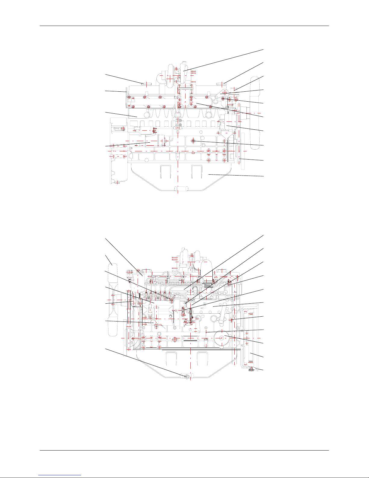
OUTLINE GENERAL
GENERAL
1 OUTLINE
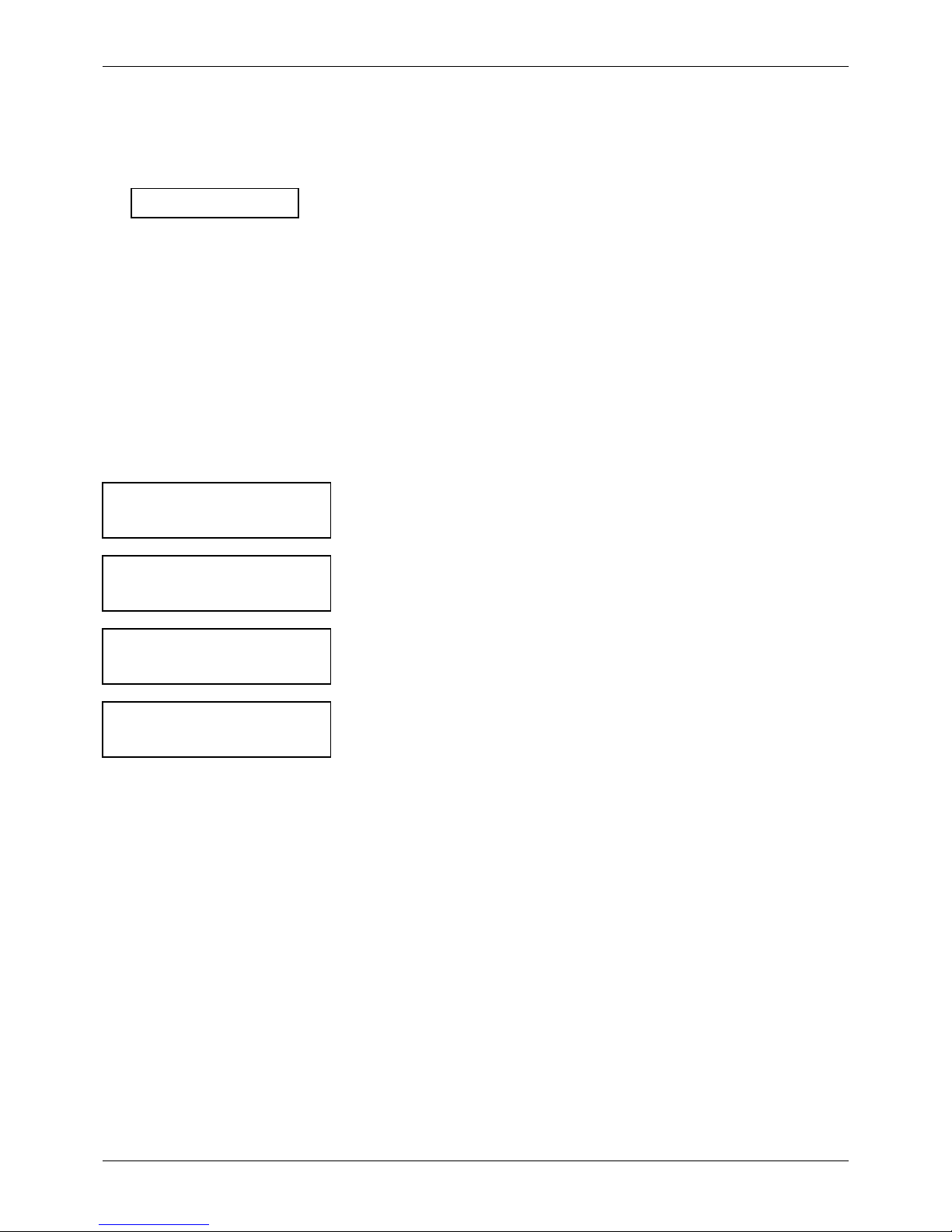
1.1 External View
[S4S - Standard]
Remark: Direction of rotation of this engine is counterclockwise as seen from flywheel side.
Alternator
Hanger
V-belt
Oil pan
RIGHT SIDE VIEW
Oil filler
Exhaust manifold
Engine serial number
Starter
REAR
FRONT
Hanger
Thermostat
Thermoswitch
Oil pressure switch
LEFT SIDE VIEW
REAR
FRONT
Fuel filter
Fan
Water pump
Fuel feed pump
Oil drain plug
Dipstick
Fuel injection nozzle
Inlet manifold
Governor
Speed control lever
Fuel injection pump
Flywheel
Oil filter
Air vent screw
Flywheel housing
Coolant drain plug
Stop solenoid
9 / 170
Service Manual Mitsubishi SS-Series diesel engines
Version 08/2004
OUTLINE
ENGLISH
GENERAL
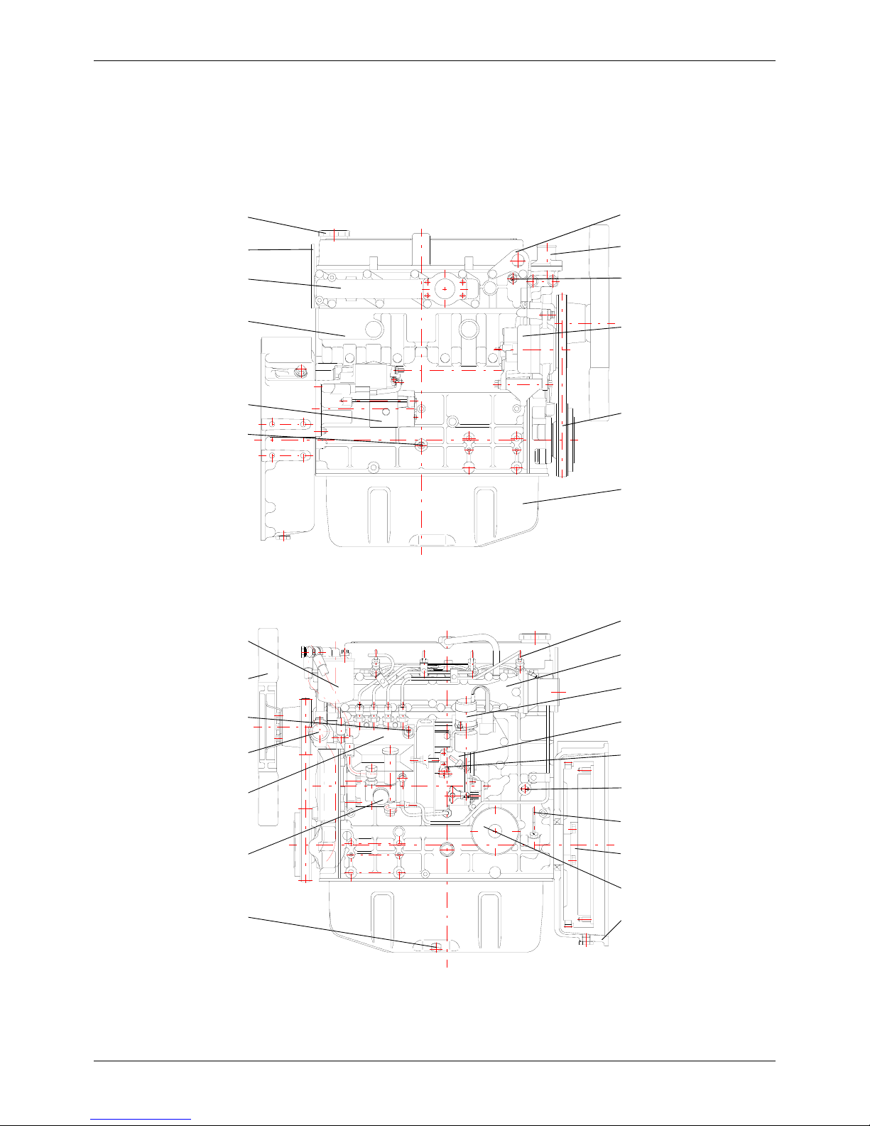
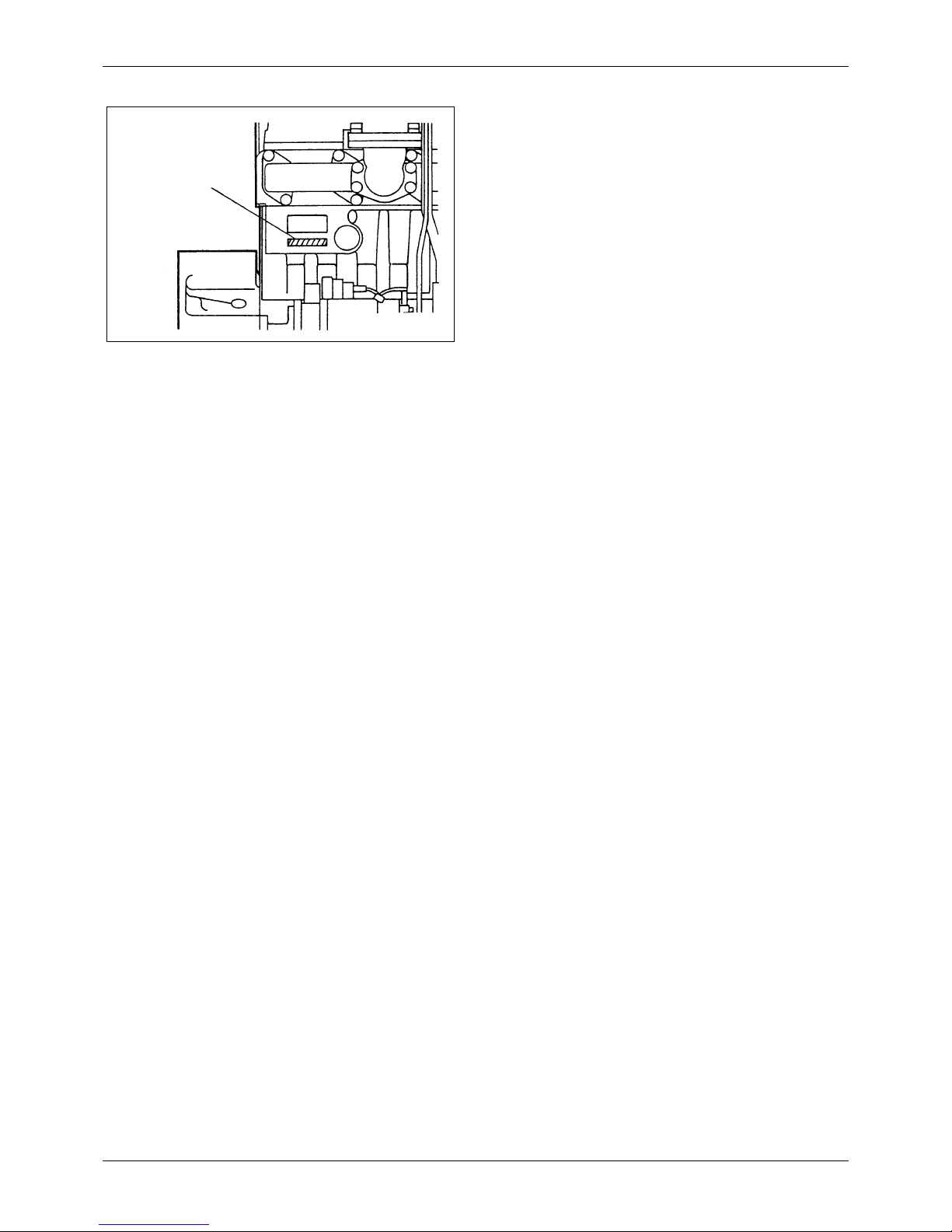
[S4S-DT - Standard]
Remark: Direction of rotation of this engine is counterclockwise as seen from flywheel side.
Thermostat
Turbocharger
Alternator
V-belt
Oil pan
FRONT
Oil filler
Exhaust manifold
Engine serial number
Starter
REAR
RIGHT SIDE VIEW
Thermoswitch
Hanger
Hanger
Oil pressure switch
LEFT SIDE VIEW
REAR
FRONT
Oil drain plug
Fuel feed pump
V-belt
Water pump
Fan
Fuel filter
Fuel injection nozzle
Inlet manifold
Oil cooler
Governor
Fuel injection pump
Coolant drain plug
Dipstick
Oil filter
Flywheel
Air vent screw
Stop solenoid
Flywheel housing
Speed control lever
10 / 170
Service Manual Mitsubishi SS-Series diesel engines
Version 08/2004
ENGLISH
OUTLINE GENERAL
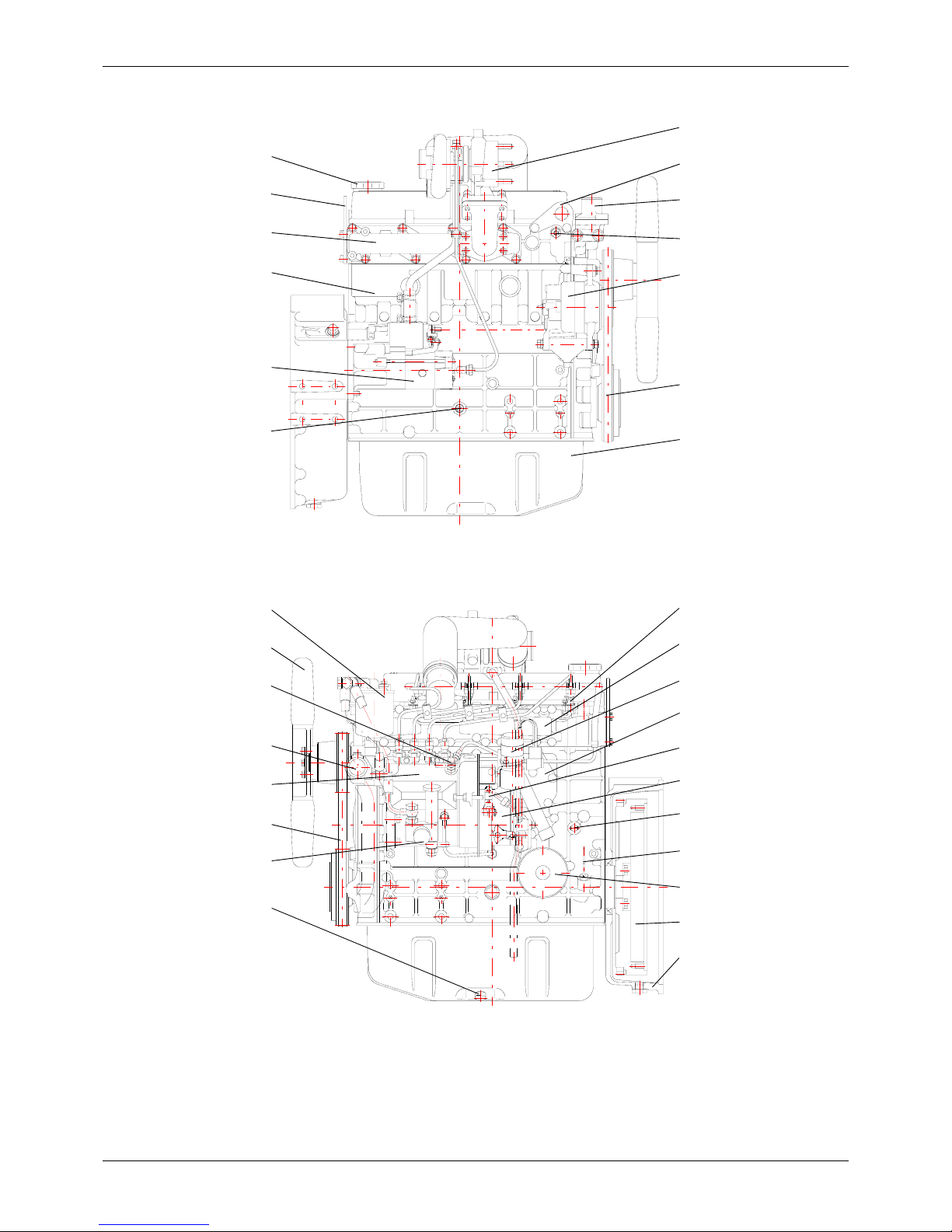
[S6S - Standard]
Remark: Direction of rotation of this engine is counterclockwise as seen from flywheel side.
Alternator
Hanger
V-belt
Oil pan
RIGHT SIDE VIEW
Oil filler
Exhaust manifold
Engine serial number
Starter
REAR
FRONT
Thermostat
Oil pressure switch
Thermoswitch
Hanger
LEFT SIDE VIEW
REAR
FRONT
Oil drain plug
Fuel filter
Fan
Water pump
Fuel injection pump
Fuel feed pump
Dipstick
Coolant drain plug
Inlet manifold
Fuel injection nozzle
Governor
Flywheel
Oil filter
Air vent screw
Flywheel housing
Stop solenoid
Speed control lever
11 / 170
Service Manual Mitsubishi SS-Series diesel engines
Version 08/2004
OUTLINE
ENGLISH
GENERAL
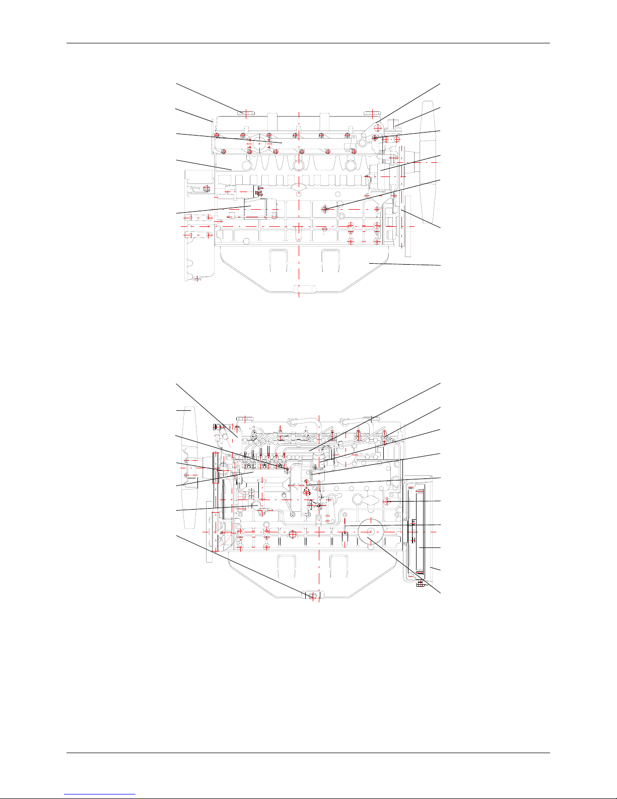
[S6S-DT - Standard]
Remark: Direction of rotation of this engine is counterclockwise as seen from flywheel side.
Thermostat
Turbo charger
Thermoswitch
Alternator
V-belt
FRONT
Oil pan
Oil filler
Engine serial number
Starter
REAR
RIGHT SIDE VIEW
Hanger
Oil pressure switch
Exhaust manifold
Oil filler
Hanger
LEFT SIDE VIEW
REAR
FRONT
Oil drain plug
Fuel feed pump
Fuel injection pump
Air vent screw
Fan
Fuel filter
Inlet manifold
Governor
Fuel injection nozzle
Speed control lever
Coolant drain plug
Dipstick
Oil filter
Flywheel housing
Water pump
Flywheel
Oil cooler
Stop solenoid
12 / 170
Service Manual Mitsubishi SS-Series diesel engines
Version 08/2004
ENGLISH
OUTLINE GENERAL
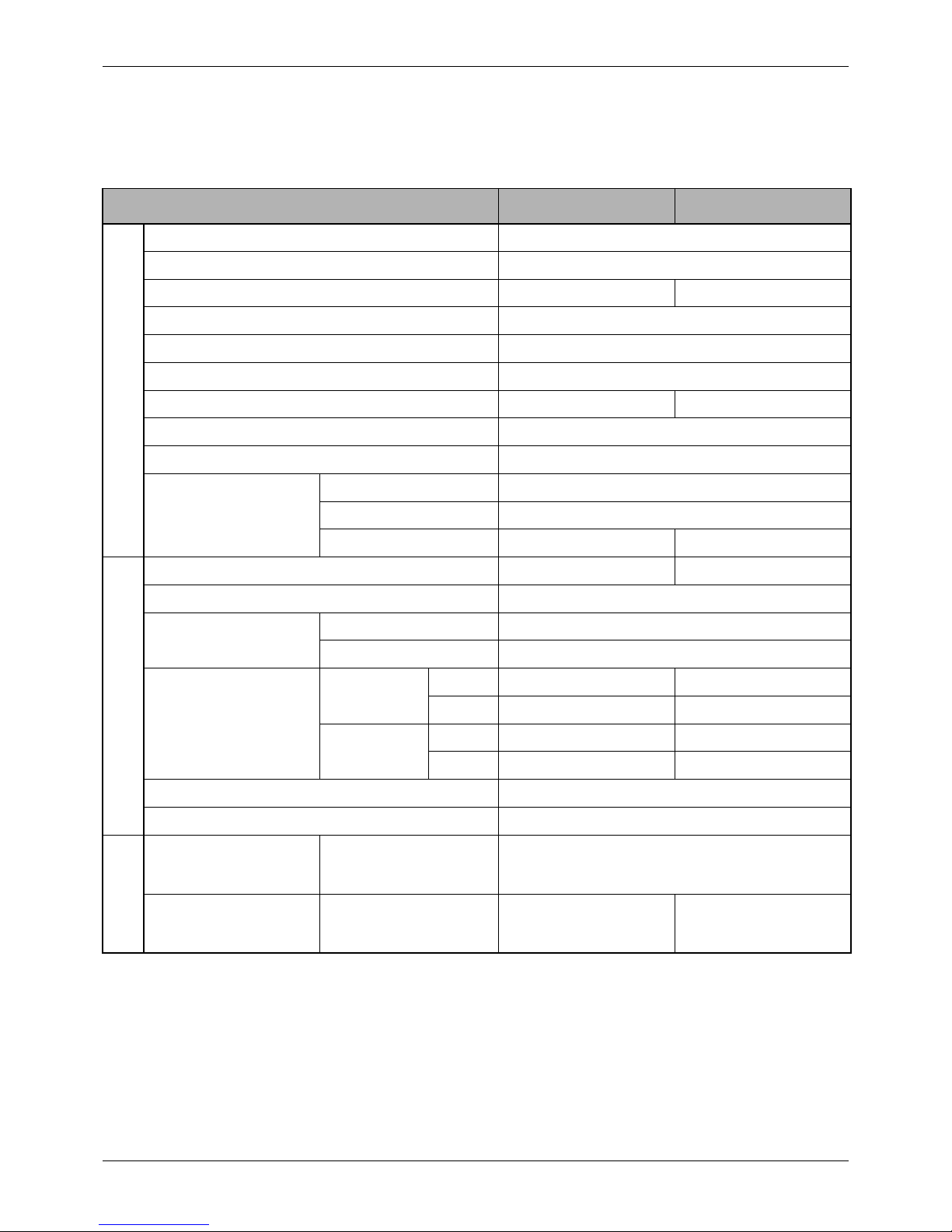
1.2 Engine Serial Number Location
The engine serial number is located on the side of the
crankcase.
1.3 Engine Model and Application
Codes
S 4 S - D T
S - Manufactured by Sagamihara Machinery Works
4 - Number of cylinders
S - Series code
D - Direct injection type
T - Equipped with turbocharger
Engine serial number
13 / 170
Service Manual Mitsubishi SS-Series diesel engines
Version 08/2004
SPECIFICATIONS
ENGLISH
GENERAL
GENERAL
2 SPECIFICATIONS
Model designation S4S S4S-DT
General
Type Water-cooled, 4-stroke cycle
No. of cylinders - arrangement 4 - in line
Combustion chamber type Swirl chamber Direct injection
Valve mechanism Overhead
Cylinder bore x stroke mm [in.] 94 x 120 [3.70 x 4.72]
Piston displacement liter [cu in.] 3.331 [203]
Compression ratio 22 : 1 17 : 1
Firing order 1 - 3 - 4 - 2
Direction of rotation Counterclockwise as viewed from flywheel side
Dimension
Overall length mm [in.] 781 [30.7]
Overall width mm [in.] 593 [23.3]
Overall heigth mm [in.] 710 [28.0] 821 [32.3]
Engine main parts
Weigth (dry) kg [lb.] 245 [540] 250 [551]
Type of cylinder sleeve Intergral with cylinder block
No. of piston ring
Compression ring 2
Oil ring 1 (w/spring expander)
Valve timing
Inlet valve
Open BTDC 30° BTDC 18°
Close ABDC 50° ABDC 54°
Exhaust valve
Open BBDC 74° BBDC 66°
Close ATDC 30° ATDC 22°
Starting system Electric-starter
Starting aid Glow plugs
Inlet and exhaust
systems
Air cleaner Type Paper element
Turbocharger Model __ TD04HL

14 / 170
Service Manual Mitsubishi SS-Series diesel engines
Version 08/2004
ENGLISH
SPECIFICATIONS GENERAL
Lubrication system
Typ e Force feed by oil pump
Engine oil
Specification Class CD oil (API Service Classification)
Capacity (engine) liter [U.S.
gal}
Approx. 10 [2.6]
(Oil pan: 9 [2.4], Filter: 1 [0.3])
Oil pump
Type Trochoid
Speed ratio to crankshaft 0.74
Capacity liter [U.S. gal]
28.6 [7.6] at 0.3 MPa (3 kgf/cm
2
) discharge pressure of
pump running at 2 230 rpm
Relief valve
Type Piston valve
Opening pressure MPa
(kgf/cm
2
) [psi]
0.35 ± 0.05 (3.5 ± 0.5) [50 ± 7]
Oil Cooler Type __ Water-cooled multi-plate
Oil filter Type Cartridge of paper element
Safety valve
Opening pressure MPa
(kgf/cm
2
) [psi]
__ 1.1 (11) [156]
Cooling system
Refill capacity (engine water jacket) liter [U.S. gal.] 5.5 [1.5] 5 [1.3]
Water pump
Type Centrifugal
Speed ration to crankshaft 1.3
Capacity liter [U.S. gal.]/
min/rpm
160 [42.3] at 0.075 MPa [0.75 kgf/cm
2
] discharge
pressure of pump runnning at 3600 rpm
Fan belt Type Low-edge B type V-belt x 1
Thermostat
Type Wax pellet
Valve opening temperature
°C [°F]
76.5 ± 1.5 [170 ± 2.7]
Fan
Type Pusher (PP)
No. of blade 6
Diameter mm [in.] 440 [17.3]
Model designation S4S S4S-DT
15 / 170
Service Manual Mitsubishi SS-Series diesel engines
Version 08/2004
SPECIFICATIONS
ENGLISH
GENERAL
Fuel system
Injection pump
Type Bosch A
Diameter of plunger mm
[in.]
7 [0.276] 9 [0.354]
Feed pump
Type Bosch, piston
Cam lobe lift mm [in.] 8 [0.315] 9 [0.354]
Governor Type Bosch RSV, centrifugal
Injection nozzle
Type of nozzle Bosch throttle Bosch hole
No. of spray orifice 1 4
Diameter of spray orifice
mm [in.]
1.0 [0.039]
0.28 [0.011] (for D/G) 0.24
[0.009] (for Power Unit)
Spray angle 0° 155°
Valve opening pressure
MPa (kgf/cm
2
) [psi]
11.77 (120) [1707] 17.65 (180) [2561]
Fuel filter Type Cartridge of paper element
Electrical system
Voltage - polarity 12V - \ ground
Starter
Model M008T75171
Type Pinion shift
Output V - kW 12 - 2.2
No. of pinion teeth/flywheel
ring gear teeth
10 / 122
Alternator
Type 3-phase, with rectifier
Output V - A 12 - 50
Working speed rpm 1000 to 18000
Rated output generating
speed rpm
5000
Maximum permissible
speed rpm
22000
Speed ratio to crankshaft 2.0
Glow plug
Type Sheathed
Rated voltage - current V A
Direct injection: 11 - 5.5 (30 sec. rating)
Swirl chamber: 10.5 - 9.7 (30 sec. rating)
Stop solenoid (option)
Rated voltage V 12
Rated temp. °C [°F] 20 [68]
Model designation S4S S4S-DT
16 / 170
Service Manual Mitsubishi SS-Series diesel engines
Version 08/2004
ENGLISH
SPECIFICATIONS GENERAL
Model designation S6S S6S-DT
General
Type Water-cooled, 4-stroke cycle
No. of cylinders - arrangement 6 - in line
Combustion chamber type Swirl chamber Direct injection
Valve mechanism Overhead
Cylinder bore x stroke mm [in.] 94 x 120 [3.70 x 4.72]
Piston displacement liter [cu in.] 4.996 [305]
Compression ratio 22 : 1 17 : 1
Firing order 1 - 5 - 3 - 6 - 2 - 4
Direction of rotation Counterclockwise as viewed from flywheel side
Dimension
Overall length mm [in.] 1033 [40.7] SG type, 1029 [40.5] SP type
Overall width mm [in.] 593 [23.3] 626 [24.6]
Overall heigth mm [in.] 748 [29.4] 896 [35.3]
Engine main parts
Weigth (dry) kg [lb.] 340 [750] 350 [772]
Type of cylinder sleeve Intergral with cylinder block
No. of piston ring
Compression ring 2
Oil ring 1 (w/spring expander)
Valve timing
Inlet valve
Open BTDC 30° BTDC 18°
Close ABDC 50° ABDC 54°
Exhaust valve
Open BBDC 74° BBDC 66°
Close ATDC 30° ATDC 22°
Starting system Electric-starter
Starting aid Glow plugs
Inlet and exhaust
systems
Air cleaner Type Paper element
Turbocharger Model __ TE06H
17 / 170
Service Manual Mitsubishi SS-Series diesel engines
Version 08/2004
SPECIFICATIONS
ENGLISH
GENERAL
Lubrication system
Typ e Force feed by oil pump
Engine oil
API Service Classification CD
Refill capacity liter [U.S.
gal}
Whole system: Approx. 12 liter [3.2 U.S. gal];
Oil pan: 11 liters [2.9 U.S. gal], Filter: 1 liters [0.3 U.S. gal]
Oil pump
Type Trochoid
Speed ratio to crankshaft 0.74
Capacity liter [U.S. gal] /
min
38.7 [10.2] at 0.3 MPa (3 kgf/cm
2
) discharge pressure of
pump running at 2 230 rpm
Oil pressure relief valve
Type Piston valve
Opening pressure MPa
(kgf/cm
2
) [psi]
0.35 ± 0.05 (3.5 ± 0.5) [50 ± 7]
Oil Cooler Type __ Water-cooled multi-plate
Oil filter Type Cartridge of paper element
Safety valve
Opening pressure MPa
(kgf/cm
2
) [psi]
__ 1.1 (11) [156]
Cooling system
Refill capacity (engine water jacket) liter [U.S. gal.] 5.5 [1.5] 5 [1.3]
Water pump
Type Centrifugal
Speed ration to crankshaft 1.3
Capacity liter [U.S. gal.]/
min/rpm
160 [42.3] at 0.075 MPa [0.75 kgf/cm
2
] discharge
pressure of pump runnning at 3600 rpm
Fan belt Type Low-edge B type V-belt x 1
Thermostat
Type Wax pellet
Valve opening temperature
°C [°F]
76.5 ± 1.5 [170 ± 2.7]
Fan
Type Pusher (PP)
No. of blade 7
Diameter mm [in.] 500 [19.7]
Model designation S6S S6S-DT

18 / 170
Service Manual Mitsubishi SS-Series diesel engines
Version 08/2004
ENGLISH
SPECIFICATIONS GENERAL
Fuel system
Injection pump
Type Bosch A
Diameter of plunger mm
[in.]
7 [0.276] 9 [0.354]
Feed pump
Type Bosch, piston
Cam lob lift mm [in.] 8 [0.315] 9 [0.354]
Governor Type Bosch RSV, centrifugal
Inspection nozzle
Type of nozzle Bosch throttle Bosch hole
No. of discharge orifice 1 4
Diameter of discharge
orifice mm [in.]
1.0 [0.039]
0.28 [0.011] (for D/G) 0.24
[0.009] (for Pover Unit)
Discharge angle 0° 155°
Valve opening pressure
MPa (kgf/cm
2
) [psi]
11.77 (120) [1707] 17.65 (180) [2561]
Fuel filter Type Cartridge of paper element
Electrical system
Voltage - polarity 12V - \ ground
Starter
Model M008T50271
Type Pinion shift
Output V - kW 12 - 3
No. of pinion teeth/flywheel
ring gear teeth
10 / 122
Alternator
Type 3-phase, with rectifier
Output V - A 12 - 50
Working speed rpm 1000 to 18000
Rated output generating
speed rpm
5000
Maximum permissible
speed rpm
22000
Speed ratio to crankshaft 2.0
Glow plugs
Type Sheathed
Rated voltage - current V A
Direct injection: 11 - 5.5 (30 sec. rating)
Swirl chamber: 10.5 - 9.7 (30 sec. rating)
Stop solenoid (option)
Rated voltage V 12
Rated temp. °C [°F] 20 [68]
Model designation S6S S6S-DT

19 / 170
Service Manual Mitsubishi SS-Series diesel engines
Version 08/2004
TIPS ON DISASSEMBLY AND
REASSEMBLY
ENGLISH
GENERAL
GENERAL
3 TIPS ON DISASSEMBLY
AND REASSEMBLY
This service manual covers recommended procedures
to be followed when servicing diesel engines. It also
contains information on special tools required and
basic safety precautions.
It is the responsibility of service personnel to be familiar
with these requirements, precautions and potential
hazards and to discuss these points with their foreman
or supervisor.
Study this manual carefully and observe the following
general precautions to prevent serious personal injury
and to avoid damage to the engine, equipment and
parts.
3.1 Disassembly
1. Use the correct tools and instruments. Serious
injury or damage to the engine can result from
using the wrong tools and instruments.
2. Use an overhaul stand or work bench if necessary.
Also, use assembly bins to keep the engine parts
in order of removal.
3. Lay down disassembled or cleaned parts in the
order in which they were removed. This will save
you time at reassembly.
4. Pay attention to the marks on assemblies,
components and parts for positions or directions.
Put on your own marks, if necessary, to aid
reassembly.
5. Carefully check each part for faults during removal
or cleaning. Signs of abnormal wear will tell if parts
or assemblies are functioning improperly.
6. When lifting or carrying heavy parts, get someone
to help you if the part is too awkward for one
person to handle. Use jacks and chain blocks
when necessary.

20 / 170
Service Manual Mitsubishi SS-Series diesel engines
Version 08/2004
ENGLISH
TIPS ON DISASSEMBLY AND
REASSEMBLY GENERAL
3.2 Reassembly
1. Wash all engine parts, except oil seals, O-rings,
rubber seals, etc. in cleaning solvent and dry them
with compressed air.
2. Use only the correct tools and instruments.
3. Use only good quality lubricating oils and greases.
Be sure to apply a coat of oil, grease, or sealant to
parts as specified. (Refer to section 3, of Group 2,
“Maintenance Standards”.)
4. Use a torque wrench to tighten parts when
specified tightening torques are required. (Refer to
section 2, of Group 2, “Maintenance Standards”.)
5. Replace all gaskets and packing. Apply
appropriate amount of adhesive or liquid gasket
when required.

21 / 170
Service Manual Mitsubishi SS-Series diesel engines
Version 08/2004
ENGLISH
MAINTENANCE STANDARDS
22 / 170
Service Manual Mitsubishi SS-Series diesel engines
Version 08/2004
ENGLISH
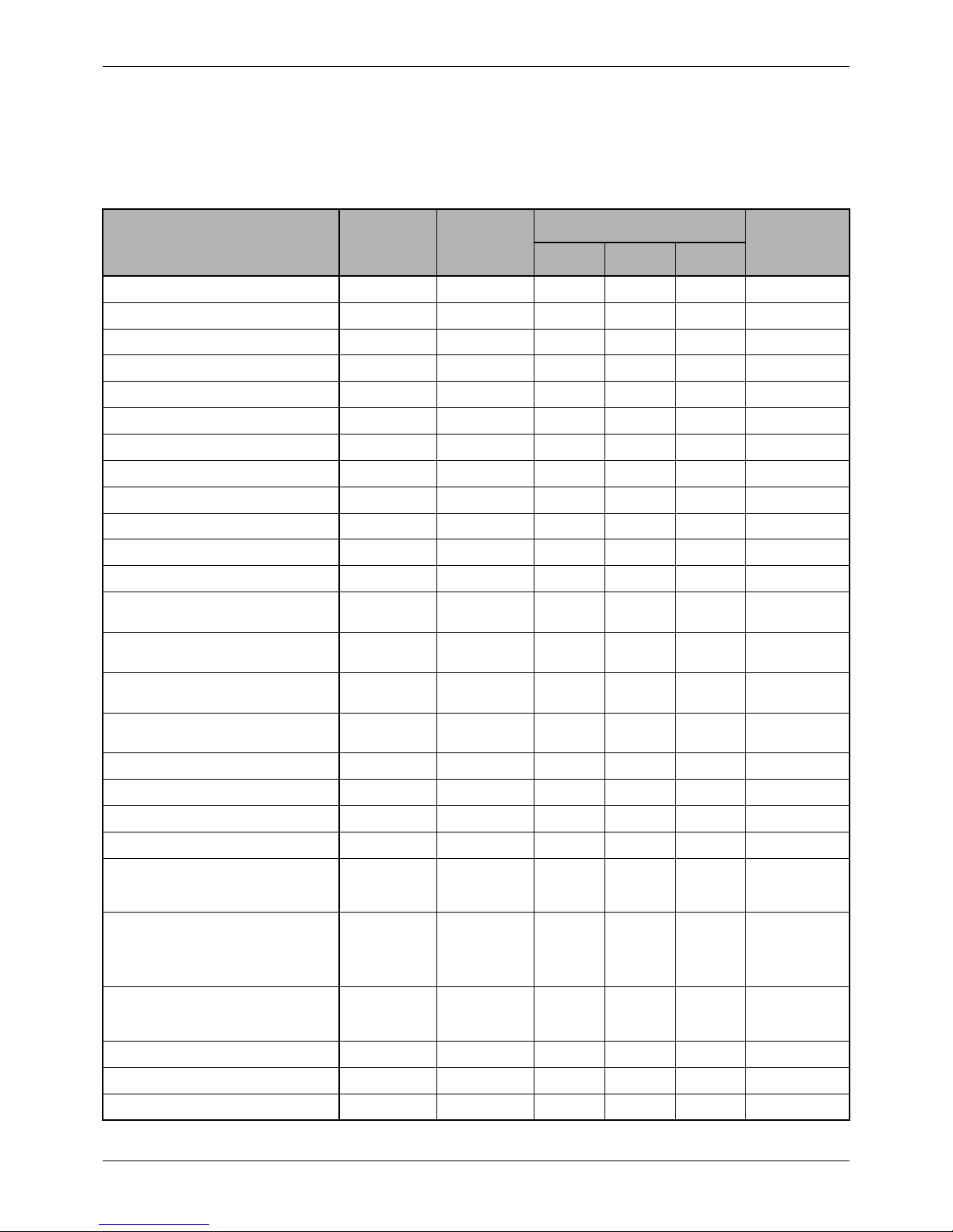
MAINTENANCE STANDARDS TABLE MAINTENANCE STANDARDS
MAINTENANCE STANDARDS
4 MAINTENANCE
STANDARDS TABLE
Unit: mm [in.]
DI: Direct injection
SC: Swirl chamber
Group Inspection Point
Nominal
Value
Assembly
Standard
(Standard
Clearance)
Repair Limit
(Clearance)
Service
Limit
(Clearance)
Remark
General
Maximum rpm, (no-load)
According to engine
specification
Adjust governor setting.
Minimum rpm, (no-load)
Compression
pressure MPa
(kgf/cm
2
) [psi]
DI
2.9 (30) [427] at
300 rpm
2.6 (27) [384]
Oil and water temp.
20 to 30°C [68 to 86°F]
SC
3.2 (33) [469] at
300 rpm
2.8 (29) [413]
Engine oil pressure MPa (kgf/
cm
2
) [psi]
0.3 to 0.5 (3 to 5) [43 to 71] at
1500 rpm
0.15 (1.5)
[21.3]
Oil temperature
70 to 90°C
[158 to 194°F]
0.1 (1) [14.2] or more at idling 0.05 (0.5) [7]
Valve timing
Inlet valves open
Inlet valves close
Exhaust valves open
Exhaust valves closed
DI
BTDC 18°
ABDC 54°
BBDC 66°
ATDC 22°
±3° (crank
angle)
SC
BTDC 30°
ABDC 50°
BBDC 74°
ATDC 30°
±3° (crank
angle)
Valve clearance (cold) 0.25 [0.0098] Bolt inlet and exhaust valves.
Fuel injection timing
The timing for each model of
engine varies according to its
specification. Be sure to verify
the timing by referring to the
specifications of each model.
V-belt deflection 12 [0.5], approx.
Push belt inward with thumb
pressure and measure
deflection.
Crankcase
Crankcase
Warpage of
gasket contact
surface
0.05 [0.0020] or
less
0.20
[0.0079]
Regrind if warpage is minor.
Cylinder
Inside diameter
94
[3.70]
94.000 to 94.035
[3.7008 to
3.7022]
94.200
[3.7087]
94.700
[3.7283]
Refinish cylinder to 0.25
[0.0098] or 0.50 [0.0197]
oversize of normal value by
honing and use the same
oversize pistons and piston
rings.
Circularity
0.01 [0.0004] or
less
Ta pe r
0.015 [0.0006] or
less
Main bearing
Clearance
between
bearing and
journal
(0.050 to 0.110)
([0.0020 to
0.0043])
(0.200)
([0.0079])
–0.09 [–0.035]
as journal
diameter
which is 78
[3.07]
If repair limit is reached,
replace bearings. If it is
exceeded, regrind journals and
use undersize bearings.
Bearing undersizes:
0.25 [0.0098]
0.50 [0.0197]
0.75 [0.0295]
23 / 170
Service Manual Mitsubishi SS-Series diesel engines
Version 08/2004
MAINTENANCE STANDARDS TABLE
ENGLISH
MAINTENANCE STANDARDS
Group Inspection Point
Nominal
Value
Assembly
Standard
(Standard
Clearance)
Repair Limit
(Clearance)
Service
Limit
(Clearance)
Remark
Crankcase
Tappet bore
Inside diameter
14.000 to 14.018
[0.5512 to 0.5519]
14.100
[0.5551]
Clearance between
tappet and bore
(0.016 to 0.052)
([0.0006 to 0.0021])
(0.080)
([0.0031])
If it exceeds the repair limit,
replace tappets.
Camshaft bore
Clearance
between
camshaft
and journal
Front and
middle
(0.070 to 0.118)
([0.0028 to 0.0047])
(without bushings)
(0.15)
([0.0059])
If it exceeds the repair limit,
refinish bores and install
bushings, or replace camshaft.
Rear
(0.070 to 0.110)
([0.0028 to 0.0043])
(without bushings)
(0.040 to 0.119)
([0.0016 to 0.0047])
(with bushings)
(0.15)
([0.0059])
If it exceeds the repair limit,
replace bushings. Ream if
necessary.
Cylinder head
Cylinder head
Warpage of gasket
contact surface
0.05 [0.0020] or
less
0.20
[0.0079]
Regrind if warpage is minor
Compressed thickness
of gasket
1.2
[0.05]
±0.05
[±0.002]
Valve and valve guide
Diameter of
valve stem
Inlet valve
8
[0.31]
7.940 to 7.955
[0.3126 to 0.3132]
7.900
[0.3110]
Exhaust
valve
7.920 to 7.940
[0.3118 to 0.3126]
7.850
[0.3091]
Clearance
between
guide and
stem
Inlet valve
(0.065 to 0.095)
([0.0026 to 0.0037])
(0.200)
([0.0079])
Exhaust
valve
(0.080 to 0.115)
([0.0032 to 0.0045])
Height to top of valve
guide
11. 5
[0.45]
±0.1
[±0.004]
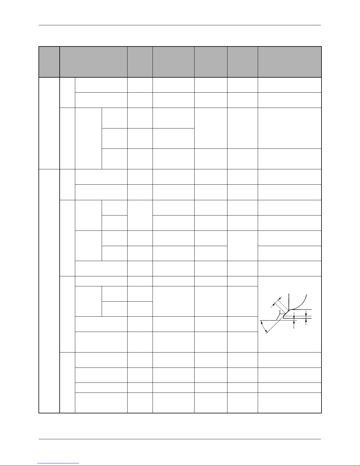
Valve seat
Angle 30°
Val ve
sinkage
Inlet valve
0.4
[0.016]
±0.1
[±0.004]
1.0
[0.039]
Exhaust
valve
0.5
[0.020]
Width
1.4
[0.055]
±0.14
[±0.0055]
1.8
[0.071]
Valve margin
2.13
[0.0839]
Up to 1.83
[0.0720] by
refacing
Val v e sp r i ng
Free length
48.85
[1.92]
47.60
[1.87]
Squareness 1.5° or less
Squareness of ends with
respect to center line
Set length 43 [1.69]
Set force N (kgf) [lbf]
176 to 196
(18 to 20)
[40 to 44]
147
(15)
[33]
Sea
t
width
Valve seat
angle
Val ve
sinkage
Val ve
margin

24 / 170
Service Manual Mitsubishi SS-Series diesel engines
Version 08/2004
ENGLISH
MAINTENANCE STANDARDS TABLE MAINTENANCE STANDARDS
Cylinder head
Rocker arm
Inside diameter of rocker
bushing
19
[0.75]
19.010 to 19.030
[0.7484 to 0.7492]
Diameter of rocker shaft
18.980 to 19.000
[0.7472 to 0.7480]
Clearance between
bushing and shaft
(0.010 to 0.050)
([0.0004 to 0.0020])
(0.070)
([0.0028])
Val ve
pushrod
Deflection 0.3 [0.012] or less 1/2 of dial indicator reading
Main moving parts
Crankshaft
Deflection
0.02 [0.0008] or
less
0.05
[0.0020]
Journal diameter
78
[3.07]
77.955 to 77.970
[3.0691 to 3.0697]
77.850
[3.0650]
77.100
[3.0354]
Crankpin diameter
58
[2.28]
57.955 to 57.970
[2.2817 to 2.2823]
57.800
[2.2756]
Center to center distance
between journal and
crankpin
60
[2.36]
±0.04 [±0.0016]
Parallelism between
journal and crankpin
Runout: 0.01
[0.0004] or less
(over crankpin
length)
Circularity of journal and
crankpin
0.01 [0.0004] or
less
0.03
[0.0012]
Taper of journal and
crankpin
Fillet radius of journal
and crankpin
3
[0.12]
±0.2 [±0.008]
End play
33
[1.30]
(0.100 to 0.264)
([0.0039 to 0.0104])
(0.300)
([0.0118])
If thrust plate clearance
exceeds the repair limit,
replace thrust plates. If it is
exceeded, use oversize thrust
plates.
Thrust plate oversizes:
0.15 [0.0059]
0.30 [0.0118]
0.45 [0.0177]
Group Inspection Point
Nominal
Value
Assembly
Standard
(Standard
Clearance)
Repair Limit
(Clearance)
Service
Limit
(Clearance)
Remark
25 / 170
Service Manual Mitsubishi SS-Series diesel engines
Version 08/2004
MAINTENANCE STANDARDS TABLE
ENGLISH
MAINTENANCE STANDARDS
Main moving parts
Piston
Outside diameter (at skirt)
Standard
94
[3.70]
93.955 to 93.985
[3.6990 to 3.7002]
93.770
[3.6917]
0.25
[0.0098]
oversize
94.205 to 94.235
[3.7089 to 3.7100]
94.020
[3.7016]
0.50
[0.0197]
oversize
94.455 to 94.485
[3.7187 to 3.7199]
94.270
[3.7114]
Protrusion
DI
0.05 to 0.45
[0.0020 to 0.0177]
Check bearing clearance.
SC
–0.25 to 0.15
[–0.0098 to 0.0059]
Clearance between
piston pin and bore
(0.000 to 0.016)
([0.0000 to 0.0006])
(0.050)
([0.0020])
Piston weight difference
per engine
5 g [0.18 oz] or less
Piston ring
Clearance between
groove and ring
No. 1 ring
(0.07 to 0.11)
([0.0028 to 0.0043])
(0.200)
([0.0079])
No. 2 ring
2.0
[0.079]
(0.045 to 0.085)
([0.0018 to 0.0034])
(0.150)
([0.0059])
Oil ring
4.5
[0.177]
(0.025 to 0.065)
([0.0010 to 0.0026])
(0.150)
([0.0059])
Clearance
between
ends
No. 1, 2
rings
0.30 to 0.50
[0.0118 to 0.0197]
1.50
[0.0591]
Oil ring
Piston pin
Diameter
30
[1.18]
29.994 to 30.000
[1.1809 to 1.1811]
Clearance between pin
and bushing
(0.020 to 0.051)
([0.0008 to 0.0020])
(0.080)
([0.0032])
Connecting rod
Inside diameter of
bushing
30
[1.18]
30.020 to 30.045
[1.1819 to 1.1829]
Bend and twist
0.10/100 [0.0039/
3.94] or less
0.15
[0.0059]
Clearance between
crankpin and connecting
rod bearing
(0.030 to 0.090)
([0.0012 to 0.0035])
(0.200)
([0.0079])
End play
33
[1.30]
(0.15 to 0.35)
([0.0059 to 0.0138])
(0.50)
([0.020])
Replace connecting rod.
Rod weight difference
per engine
10 g [0.35 oz] or
less
Flywheel
Flatness
0.15 [0.0059] or
less
0.50
[0.020]
Face runout
Deflection
0.02 [0.0008] or
less
0.05
[0.0020]
Straighten by cold working or
replace.
Group Inspection Point
Nominal
Value
Assembly
Standard
(Standard
Clearance)
Repair Limit
(Clearance)
Service
Limit
(Clearance)
Remark
26 / 170
Service Manual Mitsubishi SS-Series diesel engines
Version 08/2004
ENGLISH
MAINTENANCE STANDARDS TABLE MAINTENANCE STANDARDS
Group Inspection Point
Nominal
Value
Assembly
Standard
(Standard
Clearance)
Repair Limit
(Clearance)
Service
Limit
(Clearance)
Remark
Timing gears
Camshaft
Cam lift C
Inlet
valve
DI
A= 46.918
[1.8472 ]
6.682
[0.2631]
6.182
[0.2434]
SC
A= 46.916
[1.8471 ]
6.684
[0.2632]
6.184
[0.2435]
Exhaust
valve
DI
A= 46.878
[1.8456 ]
6.722
[0.2647]
6.222
[0.2450]
SC
A= 46.880
[1.8457 ]
6.720
[0.2646]
6.220
[0.2450]
Journal
diameter
No. 1, 2 (S4S)
No. 1, 2, 3 (S6S)54[2.13]
53.94 to 53.96
[2.1236 to 2.1244]
53.90
[2.1220]
No. 3 (S4S)
No. 4 (S6S)
53
[2.09]
52.94 to 52.96
[2.0842 to 2.0850]
52.90
[2.0827]
End play
5
[0.20]
(0.10 to 0.25)
([0.0039 to 0.0098])
(0.30)
([0.0118])
Replace thrust plates.
Idler gear
Clearance between shaft
and bushing
(0.009 to 0.050)
([0.0004 to 0.0020])
(0.100)
([0.0040])
Replace bushing.
End play
30
[1.18]
(0.05 to 0.20)
([0.0020 to 0.0079])
(0.35)
([0.0138])
Replace thrust plates.
Fit (interference) of
bushing in crankcase
bore
30
[1.18]
(0.035T to 0.076T)
([0.0014T to
0.0030T])
Backlash
(0.03 to 0.18)
([0.0012 to 0.0071])
(0.25)
([0.0098])
Replace gears.
Lubrication system
Oil pump
Clearance between
outer rotor and case
(0.20 to 0.30)
([0.0012 to 0.0018])
(0.50)
([0.0197])
Diameter of main shaft
(case side)
16
[0.63]
15.985 to 16.000
[0.6293 to 0.6299]
Diameter of main shaft
(oil pump bushing side)
14
[0.55]
13.957 to 13.975
[0.5495 to 0.5502]
Clearance between main
shaft and case
(0.032 to 0.074)
([0.0013 to 0.0029])
(0.15)
([0.0059])
Replace pump case or pump
assembly.
Clearance between main
shaft and oil pump
bushing
(0.025 to 0.111)
([0.0010 to 0.0044])
(0.200)
([0.0079])
Replace bushing or pump
assembly.
Clearance between
outer and inner rotors
(0.13 to 0.15)
([0.0051 to 0.0059])
(0.20)
([0.0079])
Clearance between
rotors and cover
(0.04 to 0.09)
([0.0016 to 0.0035])
(0.15)
([0.0059])
Replace cover or case.
Relief valve
Valve opening
pressure, MPa
(kgf/cm
2
) [psi]
0.35 ± 0.05
(3.5 ± 0.5)
[50 ± 7]
Safety valve 1.1 (11) [156] With oil cooler.
Cooling system
Thermostat
Temp. at which valve
starts opening
76.5 ± 1.5°C
[170 ± 2.7°F]
Temp. at which valve lift
is more than 8 [0.3]
90°C [194°F]
+0.1
–0.3
+0.004
–0.012
A
B
C
+0.1
–0.3
+0.004
–0.012
+0.1
–0.3
+0.004
–0.012
+0.1
–0.3
+0.004
–0.012
27 / 170
Service Manual Mitsubishi SS-Series diesel engines
Version 08/2004
MAINTENANCE STANDARDS TABLE
ENGLISH
MAINTENANCE STANDARDS
Fuel system
Injection nozzle
Valve opening
pressure, MPa
(kgf/cm
2
) [psi]
DI
17.65
(180)
[2560]
18.14 to 19.12
(185 to 195)
[2632 to 2774]
Make shim adjustment.
Pressure varies by 1 (10) [142]
per 0.1 mm [0.004 in.]
thickness of shim.
SC
11. 77
(120)
[1706]
11.77 to 12.75
(120 to 130)
[1707 to 1849]
Spray co ne
angle
DI 155° Test by means of hand tester,
using diesel fuel, at 20°C
[68°F]. If discharge pattern is
bad even after nozzle is
washed in clean diesel fuel,
replace nozzle tip.
SC 0°
Oil tightness of needle
valve seat
Seat shall hold a test pressure 2
MPa (20 kgf/cm
2
) [284 psi] lower
than valve opening pressure for
10 seconds.
Wash or replace nozzle tip.
Electrical system
Starter (12V - 2.2 kW)
Diameter of commutator
32
[1.26]
31.4
[1.24]
Runout of commutator
0.03
[0.0012]
0.1
[0.004]
Depth of commutator
mold
0.4 to 0.6
[0.016 to
0.024]
0.2 [0.008] or less
Brush
Length
18
[0.71]
11
[0.43]
Spring force, N
(kgf) [lbf]
30.4 to
38.2
(3.1 to 3.9)
[6.8 to 8.6]
19.6
(2.0)
[4.4]
Thrust clearance of
pinion shaft
0.5
[0.020]
0 or more
Pinion clearance
0.5 to 2.0
[0.020 to
0.079]
Group Inspection Point
Nominal
Value
Assembly
Standard
(Standard
Clearance)
Repair Limit
(Clearance)
Service
Limit
(Clearance)
Remark
No-load characteristics Locked characteristics Magnetic switch
Voltage, V Current, A Speed, rpm Voltage, V Current, A
Torque N·m
(kgf·m) [lbf·ft]
Switch-in voltage V
11 130 or less 3800 or more 3 1120 or less
31.36 (3.2)
[23.1] or more
8 or less
28 / 170
Service Manual Mitsubishi SS-Series diesel engines
Version 08/2004
ENGLISH
MAINTENANCE STANDARDS TABLE MAINTENANCE STANDARDS
Electrical system
Starter (12V - 3 kW)
Diameter of commutator
38.7
[1.52]
38.1
[1.50]
Runout of commutator
0.03
[0.0012]
0.1
[0.004]
Depth of commutator
mold
0.4 to 0.6
[0.016 to
0.024]
0.2 [0.008] or less
Brush
Length
17
[0.67]
11
[0.43]
Spring force, N
(kgf) [lbf]
33.3 to
45.1
(3.4 to 4.6)
[7.5 to
10.1]
17.7
(1.8)
[4.0]
Thrust clearance of
pinion shaft
0.5
[0.020]
0 or more
Pinion clearance
0.5 to 2.0
[0.020 to
0.079]
Alternator
Brush spring force, N (gf)
[lbf]
3.0 to 4.2
(310 to 430)
[0.7 to 0.9]
2.1
(210)
[0.5]
Brush heigth
18.5
[0.73]
7
[0.28]
Resistance in slip rings 2.4Ω At 20°C [68°F].
Group Inspection Point
Nominal
Value
Assembly
Standard
(Standard
Clearance)
Repair Limit
(Clearance)
Service
Limit
(Clearance)
Remark
No-load characteristics Locked characteristics Magnetic switch
Voltage, V Current, A Speed, rpm Voltage, V Current, A
Torque N·m
(kgf·m) [lbf·ft]
Switch-in voltage V
11 180 or less 3800 or more 2 1050 or less
25.0 (2.55)
[18.4] or more
8 or less
29 / 170
Service Manual Mitsubishi SS-Series diesel engines
Version 08/2004
TIGHTENING TORQUES
ENGLISH
MAINTENANCE STANDARDS
MAINTENANCE STANDARDS
5 TIGHTENING TORQUES
5.1 Important Bolts and Nuts
Description
Thread
Dia. x Pitch
(M-thread)
Width across
flats, mm
Tightening Torque
Remark
N·m kgf·m lbf·ft
Cylinder head M12 x 1.75 19 113 to 123 11.5 to 12.5 83 to 90
Rocker cover M8 x 1.25 12 10.0 to 13.0 1.0 to 1.3 7.23 to 9.40
Rocker shaft brackets M8 x 1.25 12 10.0 to 20.0 1.0 to 2.0 7.23 to 14.5
Main bearing caps M14 x 2 22 98 to 108 10.0 to 11.0 72 to 80
Connecting rod caps M10 x 1.25 14 49.0 to 59.0 5.0 to 6.0 36.2 to 43.4
Flywheel M12 x 1.25 17 78.5 to 88.3 8.0 to 9.0 57.9 to 65.1
Camshaft thrust plate M8 x 1.25 12 10.0 to 13.0 1.0 to 1.3 7.23 to 9.40
Front plate M8 x 1.25 12 10.0 to 13.0 1.0 to 1.3 7.23 to 9.40
Timing gear case M8 x 1.25 12 10.0 to 13.0 1.0 to 1.3 7.23 to 9.40
Crankshaft pulley M30 x 1.5 46 480 to 500 49 to 51 354 to 369
Idler gear thrust plate M10 x 1.25 14 29.0 to 39.0 3.0 to 4.0 21.7 to 28.9
Oil pan M8 x 1.25 12 10.0 to 13.0 1.0 to 1.3 7.23 to 9.40 Press product
Oil pan M8 x 1.25 12 27.5 to 33.4 2.8 to 3.4 20.3 to 24.6 Cast oil pan for
agricultural tractor
Rear plate M10 x 1.25 14 54.0 to 65.7 5.5 to 6.7 39.8 to 48.5 Agricultural tractor
use
Oil pan drain plug M14 x 1.5
M20 x 1.5
22
24
34.0 to 44.0
73.0 to 83.0
3.5 to 4.5
7.5 to 8.5
25.3 to 32.5
54.2 to 61.5
Fuel injection nozzle glands (direct injection
type)
M8 x 1.25 12 21.0 to 23.0 2.0 to 2.4 14.5 to 17.4
Fuel injection nozzles (swirl chamber type) M20 x 1.5 21 53.0 to 64.7 5.4 to 6.6 39.1 to 47.7
Fuel injection pump delivery valve holders 22 34.0 to 39.0 3.5 to 4.0 25.3 to 28.9
Fuel leak-off pipe nut M12 x 1.5 17 20.6 to 24.5 2.1 to 2.5 15.2 to 18.1
Fuel injection pump gear (distribution type) M14 x 1.5 22 76.5 to 86.3 7.8 to 8.8 56.4 to 63.7
Fuel injection pump gear
(in-line, swirl chamber type)
(in-line, direct injection type)
M12 x 1.75
M14 x 1.5
19
22
58.8 to 68.6
83.4 to 98.0
6.0 to 7.0
8.5 to 10.0
43.4 to 50.6
61.5 to 72.3
Glow plug
(swirl chamber type)
(direct injection type)
(terminal)
M10 x 1.25
M12 x 1.25
M4 x 0.7
12
12
8
15.0 to 20.0
20.0 to 30.0
1.0 to 1.5
1.5 to 2.0
2.0 to 3.0
0.10 to 0.15
10.8 to 14.5
14.5 to 21.7
0.72 to 1.08
Exhaust Manifold
(bolt only)
(with spacer)
M8 x 1.25
M8 x 1.25
12
12
27.5 to 33.3
15.0 to 22.0
2.8 to 3.4
1.5 to 2.2
20.3 to 24.6
10.8 to 15.9
Oil pressure relief valve M22 x 1.5 27 44.1 to 53.9 4.5 to 5.5 32.5 to 39.8
Safety valve or blind plug M18 x 2 24 64.0 to 74.0 6.5 to 7.5 47.0 to 54.2
Coolant drain plug 1/4 – 18NPTF 14 35.3 to 43.1 3.6 to 4.4 26.0 to 31.8

30 / 170
Service Manual Mitsubishi SS-Series diesel engines
Version 08/2004
ENGLISH
TIGHTENING TORQUES MAINTENANCE STANDARDS
5.2 Standard Bolts
5.3 Standard Studs
Fuel injection pipe nuts M12 x 1.5 19 26.5 to 32.4 2.7 to 3.3 19.5 to 23.9
Fuel return pipe nuts M10 x 1.25 14 17.7 to 21.6 1.8 to 2.2 13.0 to 15.9
Oil pump gear M10 x 1.25 14 28.0 to 38.0 2.9 to 3.9 21.0 to 28.2
Overheat warning unit (thermoswitch) M16 x 1.5 19 20.6 to 24.5 2.1 to 2.5 15.2 to 18.1
Starter terminal B M8 x 1.25 12 9.81 to 11.8 1.0 to 1.2 7.23 to 8.68
Plug M16 x 1.5 24 39.2 to 49.0 4.0 to 5.0 28.9 to 36.2 Cylinder head
Balancer M8 x 1.25 12 27.5 to 33.4 2.8 to 3.4 20.3 to 24.6
Fuel injection pump feed pipe (flare) M12 x 1.0 17 16.0 to 23.0 1.6 to 2.3 11.6 to 16.6
Fuel injection pump eye bolt M14 x 1.5 22 15.0 to 20.0 1.5 to 2.0 10.8 to 14.5
Fuel injection pump overflow valve 17 15.0 to 20.0 1.5 to 2.0 10.8 to 14.5
Oil level sensor 1 – 1/ 16 – 12 24 49.0 to 58.8 5.0 to 6.0 36.2 to 43.4
Description
Thread
Dia. x Pitch
(M-thread)
Width across
flats, mm
Tightening Torque
Remark
N·m kgf·m lbf·ft
Thread Diameter (mm)
Torq ue
4T 7T
N·m kgf·m lbf·ft N·m kgf·m lbf·ft
M6 2.94 to 4.90 0.3 to 0.5 2.17 to 3.62 7.89 to 9.80 0.8 to 1.0 5.79 to 7.23
M8 9.80 to 12.7 1.0 to 1.3 7.23 to 9.40 14.7 to 21.6 1.5 to 2.2 10.8 to 15.9
M10 17.7 to 24.5 1.8 to 2.5 13.0 to 18.1 29.4 to 41.2 3.0 to 4.2 21.7 to 30.4
M12 29.4 to 41.2 3.0 to 4.2 21.7 to 30.4 53.9 to 73.5 5.5 to 7.5 39.8 to 54.2
Thread Diameter (mm)
Torque (tap end)
For driving in aluminum materials For driving in ferrous materials
N·m kgf·m lbf·ft N·m kgf·m lbf·ft
M8 4.90 to 5.90 0.50 to 0.60 3.62 to 4.34 11.8 to 13.7 1.2 to 1.4 8.68 to 10.1
M10 12.7 to 14.7 1.3 to 1.5 9.40 to 10.8 21.6 to 25.5 2.2 to 2.6 15.9 to 18.8
 Loading...