

Mitsubishi Heavy Industries RMA502A001, RKX502A007B, RKW502A200D, RKW502A200B, RKX502A001C Service Support Handbook
...
SERVICE
SUPPORT
HANDBOOK
www.dwgeire.ie
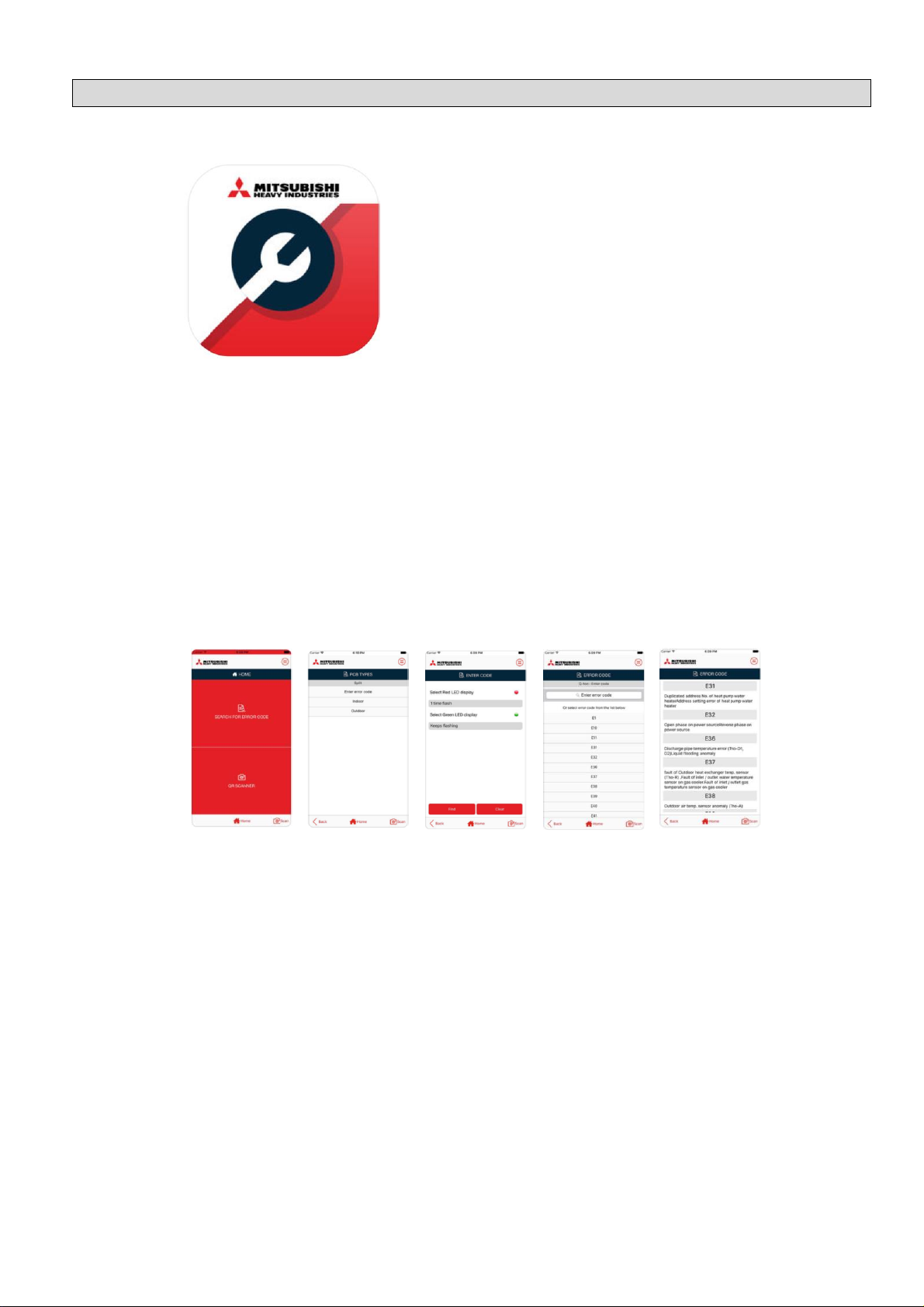
MHI e-service
DCSL Software Ltd
Free
Compatibility
Iphone or Ipad on IOS9.3 or later Android devices on 4.3 or later.
Screenshots
Description
MHI e-service is an application that enables users to make a quick search of the meaning
of error codes that may appear when there is a malfunction in "Mitsubishi Heavy Industries
Thermal Systems, Ltd" Air conditioning system, and the probable cause of the
malfunction.
In addition this application enables you to scan unit's QR code and search the meaning
of error codes depending on the model type.
The application covers "Mitsubishi Heavy Industries Thermal Systems, Ltd" Air conditioning
systems: Split (RAC & PAC), VRF, Q-ton & A2W.
The MHI e-service app is a free download available from Google Play for Android devices
(4.03 or later), or the Apple App Store for IOS devices (IOS9.3 or later).
MHI e-service app

WARNING
The information contained in this ‘Service Support Handbook’ is intended for use by
qualified service technicians familiar with safety procedures and equipped with the
proper tools and test instruments. Additionally, the information presented here is not a
replacement for, nor a substitute to the Manufacturers Technical Manuals.
MHI Air Conditioners contain pressurized refrigerants that are harmful to the atmosphere
so all refrigeration works must be performed by a qualified "F-Gas" registered person.
Please do not remove any covers, or attempt any repair or measurement on any MHI
LTD. product, unless you are suitably qualified and licensed to do so.
Repairs made by unqualified persons can result in hazards to you and others.
Technical Assistance is available Monday to Friday
between the hours of 08:00 and 17:00
on 03301 235 598
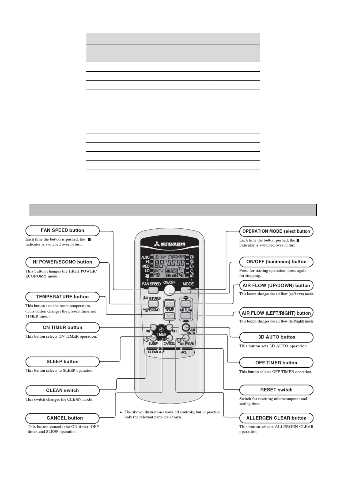
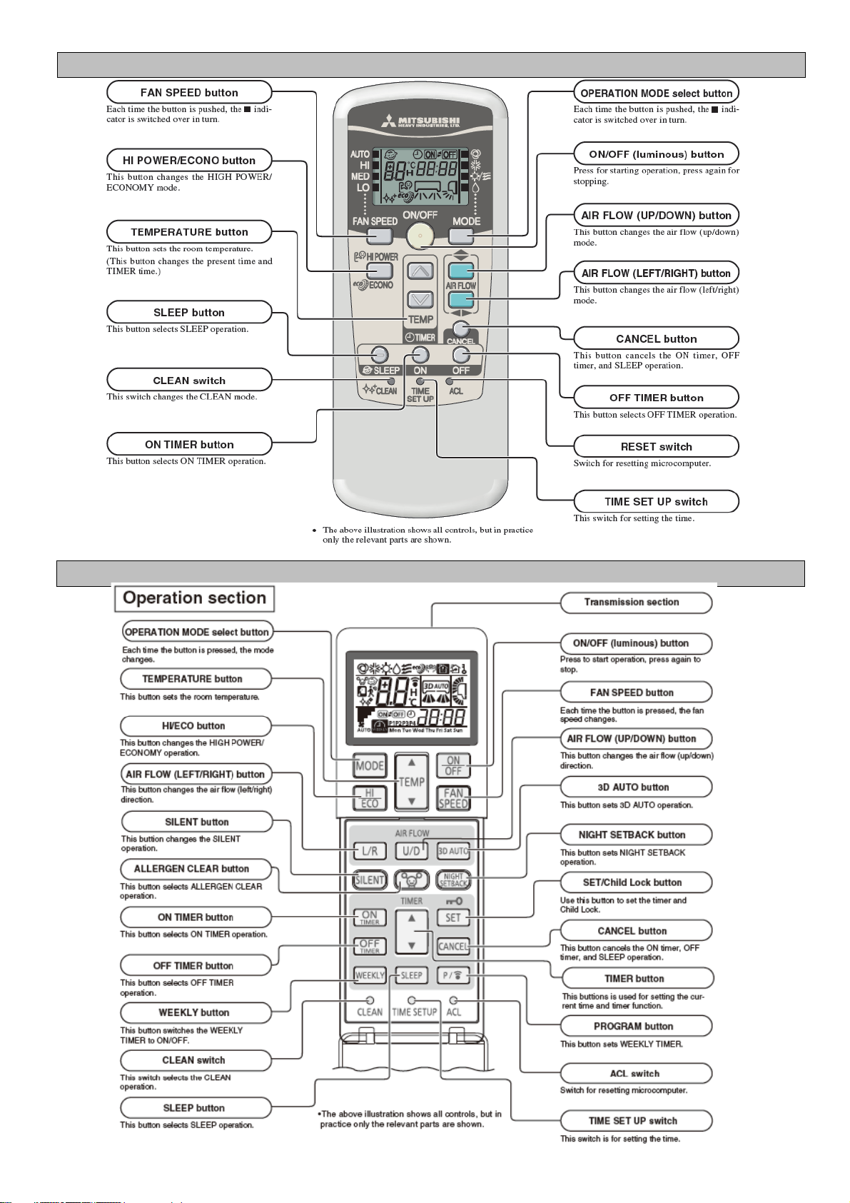
Hi-Wall Mounted Split Systems - Remote Controls of SRK
Before Proceeding to RAC Self Diagnosis Information,
ensure the correct Remote Control is being used.
Indoor Model
Remote Control
SRK--HC-S, HC-S1, HD-S, ZD-S, SKM--ZD-S
RMA502A001
SRK--HG-S
RKX502A007B
SRK--ZE-S, SRK--ZE-S1, SRK--ZR-S
RKW502A200D
SRK--ZFX-S, SRK--ZGX-S
RKW502A200B
SRK--ZG-S, ZHX-S, ZIX-S
RKX502A001C
SRK--ZJ-S, ZJ-S1, ZJX-S, ZJX-S1
SRK--ZM-S, SRK--ZMX-S, SRK--ZR-S
RLA502A701R
SRK--ZS-S
RLA502A701L
SRK--ZSX-S
RLA502A700K
SRF--ZMX-S
RLA502A700C
SRK--ZMP-S
RKX502A001P
SRK--ZSP-S
RKX502A007P
RKX502A001C
RKW502A200
RLA502A701R
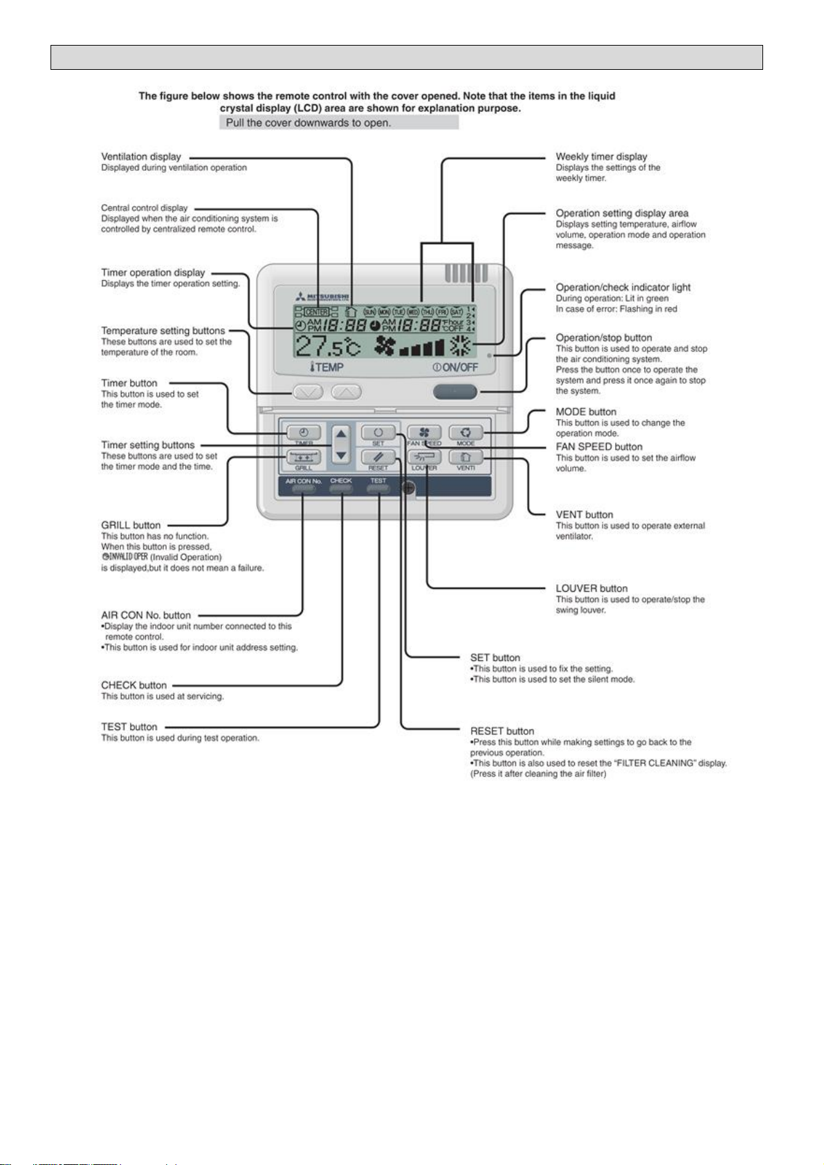
RC-E5 Layout
To access the RC-E5 Remote Controls Operation Data function, press the "CHECK" button on the MASTER remote control.
On 'Operation data' press the "SET" button.
If 'I/U No' is displayed select the unit number required, using the "/\" and "\/" buttons above the "CHECK" button, then
press the "SET" button
All navigation is carried out using the "/\" and "\/" buttons above the "CHECK" button.
RAC Unit
Compatibility
01
MODE
Current operation mode
ok
02
SET TEMP
°C
Set temperature
ok
03
RETURN AIR
°C
Return air sensor temperature
ok
04
SENSOR
°C
Remote control sensor temperature
ok
05
THI-R1
°C
Indoor heat exchanger sensor (on U bend)
ok
06
THI-R2
°C
Indoor heat exchanger sensor (on Capillary)
ok
07
THI-R3
°C
Indoor heat exchanger sensor (on suction header)
-
08
I/U FANSPEED
Indoor unit fan speed
-
09
DEMAND
Hz
Required frequency
-
10
ANSWER
Hz
Response frequency
-
11
I/U EEV
PULSE
Pulse rate of KX indoor unit expansion valve
-
12
TOTAL I/U RUN
Hr
Total running hours of the indoor unit
-
21
OUTDOOR
°C
Outdoor air temperature
ok
22
THO-R1
°C
Outdoor unit heat exchanger sensor
ok
23
THO-R2
°C
Outdoor unit heat exchanger sensor
-
24
COMP
Hz
Compressor frequency
ok
25
HP
MPa
High pressure (x10=Bar)
-
26
LP
Mpa
Low pressure (x10=Bar)
-
27
Td
°C
Discharge Pipe Temperature
ok
28
COMP BOTTOM
°C
Compressor base temperature
-
29
CT
Amp
Current
ok
30
TARGET SH
°C
Target Super Heat
-
31
SH
°C
Super Heat temperature
-
32
TDSH
°C
Compressor discharge pipe super heat
ok
33
PROTECTION No
Protection state number of the compressor
-
34
O/U FANSPEED
Outdoor unit fan speed
ok
35
63H1
63H1 High pressure switch on/off
-
36
DEFROST
Defrost control on/off
ok
37
TOTAL COMP RUN
Hr
Total running hours of compressor
-
38
O/U EEV1
PULSE
Pulse rate of the outdoor unit expansion valve EEVC
ok
39
O/U EEV2
PULSE
Pulse rate of the outdoor unit expansion valve EEVH
-
No. Contents of display
0 Normal
1 Discharge pipe temperature protection control
2 Discharge pipe temperature anomaly
3 Current safe control of inverter primary current
4 High pressure protection control
5 High pressure anomaly
6 Low pressure protection control
7 Low pressure anomaly
8 Anti-frost prevention control
9 Current cut
10 Power transistor protection control
11 Power transistor anomaly (Overheat)
12 Compression ratio control
13 14 Condensation prevention control
15 Current safe control of inverter secondary current
16 Stop by compressor rotor lock
17 Stop by compressor startup failure
Details of 33 Compressor Protection Status
RC-E5 OPERATION DATA
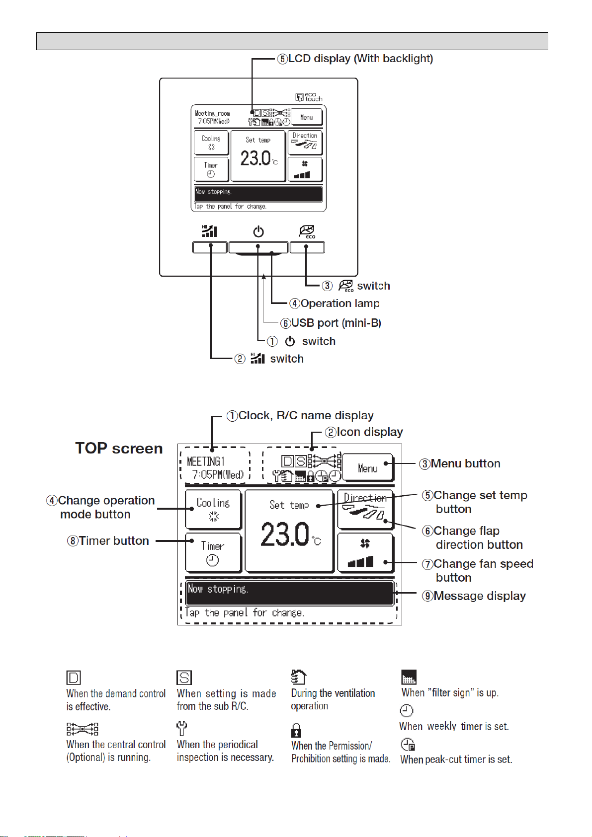
Touch panel control, which is operated by tapping the LCD screen with a finger, is employed for all functions except
1 On/Off switch, 2 Hi Power switch and 3 ECO switch.
RC-EX1 & EX1A Layout
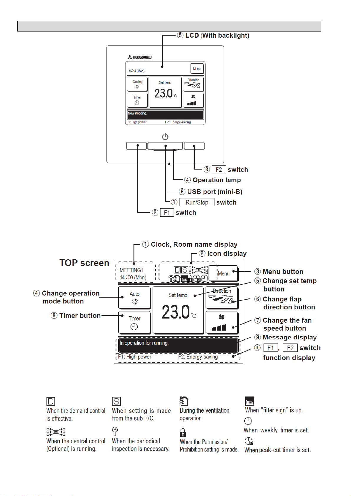
Touch panel control, which is operated by tapping the LCD screen with a finger, is employed for all functions except
1 On/Off switch, 2 Hi Power switch and 3 ECO switch.
RC-EX3 Layout

To access the RC-EX Remote Controls Operation Data function, press MENU on the MASTER remote control Front Screen.
Then press NEXT followed by SERVICE (RC-EX3 only) and SERVICE & MAINTENANCE. Enter the service pass code, press SET
then press OPERATION DATA. You can then select the indoor unit you want to view.
RAC Unit
Compatibility
01
MODE
Current operation mode
ok
02
SET TEMP
°C
Set temperature
ok
03
RETURN AIR
°C
Return air sensor temperature
ok
04
SENSOR
°C
Remote control sensor temperature
ok
05
THI-R1
°C
Indoor heat exchanger sensor (on U bend)
ok
06
THI-R2
°C
Indoor heat exchanger sensor (on Capillary)
ok
07
THI-R3
°C
Indoor heat exchanger sensor (on suction header)
-
08
I/U FANSPEED
Indoor unit fan speed
-
09
DEMAND
Hz
Required frequency
-
10
ANSWER
Hz
Response frequency
-
11
I/U EEV
PULSE
Pulse rate of KX indoor unit expansion valve
-
12
TOTAL I/U RUN
Hr
Total running hours of the indoor unit
-
21
OUTDOOR
°C
Outdoor air temperature
ok
22
THO-R1
°C
Outdoor unit heat exchanger sensor
ok
23
THO-R2
°C
Outdoor unit heat exchanger sensor
-
24
COMP
Hz
Compressor frequency
ok
25
HP
MPa
High pressure (x10=Bar)
-
26
LP
Mpa
Low pressure (x10=Bar)
-
27
Td
°C
Discharge Pipe Temperature
ok
28
COMP BOTTOM
°C
Compressor base temperature
-
29
CT
Amp
Current
ok
30
TARGET SH
°C
Target Super Heat
-
31
SH
°C
Super Heat temperature
-
32
TDSH
°C
Compressor discharge pipe super heat
ok
33
PROTECTION No
Protection state number of the compressor
-
34
O/U FANSPEED
Outdoor unit fan speed
ok
35
63H1
63H1 High pressure switch on/off
-
36
DEFROST
Defrost control on/off
ok
37
TOTAL COMP RUN
Hr
Total running hours of compressor
-
38
O/U EEV1
PULSE
Pulse rate of the outdoor unit expansion valve EEVC
ok
39
O/U EEV2
PULSE
Pulse rate of the outdoor unit expansion valve EEVH
-
No. Contents of display
0 Normal
1 Discharge pipe temperature protection control
2 Discharge pipe temperature anomaly
3 Current safe control of inverter primary current
4 High pressure protection control
5 High pressure anomaly
6 Low pressure protection control
7 Low pressure anomaly
8 Anti-frost prevention control
9 Current cut
10 Power transistor protection control
11 Power transistor anomaly (Overheat)
12 Compression ratio control
13 14 Condensation prevention control
15 Current safe control of inverter secondary current
16 Stop by compressor rotor lock
17 Stop by compressor startup failure
Details of 33 Compressor Protection Status
RC-EX OPERATION DATA
Master/ Slave and Group Settings
Master / Slave Settings
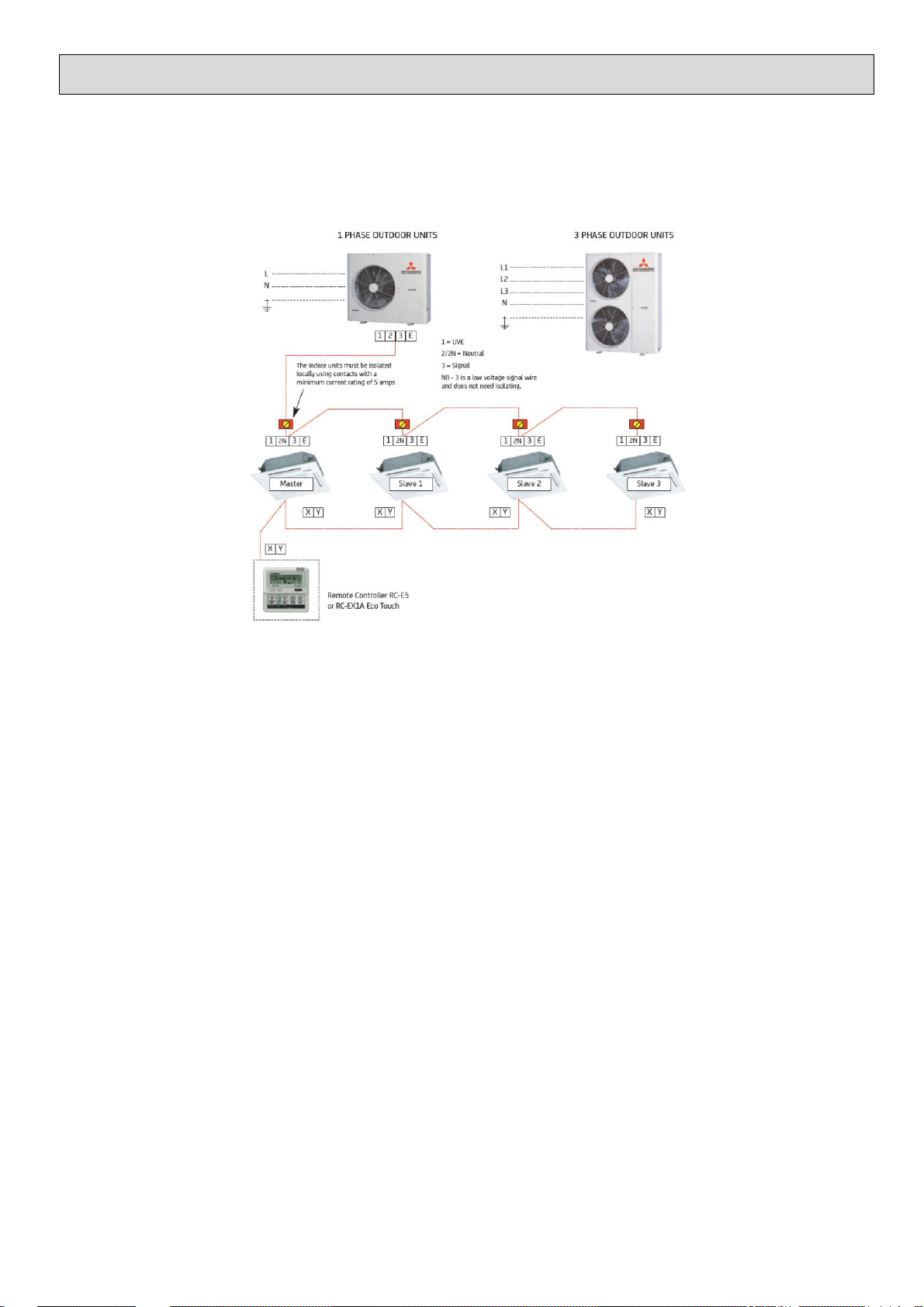
All split system indoor units are supplied set up as a master unit as default and this only needs changing when the system being
installed is a multisplit system, excluding SCM or KX systems, comprising of 2 to 4 RAC or PAC indoor units running off a
PAC single split outdoor unit. The remote control wires and all wires of the interconnecting cable go to each indoor unit
including the slave units.
When using RAC SRK indoor units, excluding ZMP/ZSP models, on a multisplit each indoor unit needs an SC-BIKN-E
interface to allow the installation of the wired remote control and setup of the master slave settings.
SYSTEM TYPE PAC Indoor Units SC-BIKN-E Interface
Unit SW5-1 SW5-2 SW3-1 SW3-2
Single Twin Triple Quad MASTER OFF OFF OFF OFF
Twin Triple Quad SLAVE 1 OFF ON OFF ON
Triple Quad SLAVE 2 ON OFF ON OFF
Quad SLAVE 3 ON ON ON ON
All indoor units on a multisplit system must be in the same space and operate off a single wired remote control as there is no
refrigerant control in the indoor units.
Group Settings
When multiple systems need to be controlled off a single RC-EX1A, RC-EX3 or RC-E5 wired remote control each system
needs to be given a different address. The system addressing is set on PAC unit indoor boards using SW2 or on RAC indoor
units via SW1 on the SC-BIKN-E interface. Upto 16 indoor units can be connected to a wired remote and that includes
multiplit systems using PAC outdoor units.
System Indoor Outdoor System Unit Group Address Master Slave
Unit Unit Type Switch Setting Switch #1 #2
1 FDT FDC Split Master SW2 0 SW5 OFF OFF
2 FDT FDC Quad Master SW2 1 SW5 OFF OFF
FDT Slave 1 SW2 1 SW5 OFF ON
FDT Slave 2 SW2 1 SW5 ON OFF
FDT Slave 3 SW2 1 SW5 ON ON
3 SRK FDC Twin Master SW1 2 SW3 OFF OFF
SRK Slave 1 SW1 2 SW3 OFF ON
4 FDUM FDC Split Master SW2 3 SW5 OFF OFF

Refrigerant Piping Information
RAC CURRENT MODELS
Model Precharged Maximum Maximum Vertical Factory Additional Pipe Sizes MCB
Piping Piping Piping Length (m) Charge Charge R410A Liquid Pipe Gas Pipe Rating
Length (m) Length (m) O/D Above I/D Above R410A (kg) per m (g/m) "" (mm) "" (mm) A
SRC25ZMP-S, 10 15 10 10 0.655 20 1/4" (6.35) 3/8" (9.52) 16
SRC35ZMP-S 15 15 10 10 0.810 N/A 1/4" (6.35) 3/8" (9.52) 16
SRC45ZMP-S 15 25 15 15 1.200 20 1/4" (6.35) 1/2" (12.7) 16
SRC25ZM-S 15 15 10 10 0.750 N/A 1/4" (6.35) 3/8" (9.52) 16
SRC35ZM-S 15 15 10 10 1.050 N/A 1/4" (6.35) 3/8" (9.52) 16
SRC50ZM-S 15 25 15 15 1.350 20 1/4" (6.35) 1/2" (12.7) 16
FDC100VNP 15 30 20 20 2.550 60 3/8" (9.52) 5/8" (15.88) 32
SRC20_35ZMX-S 15 15 10 10 1.200 N/A 1/4" (6.35) 3/8" (9.52) 16
SRC50_60ZMX-S 15 30 20 20 1.500 20 1/4" (6.35) 1/2" (12.7) 16
SRC63ZR-S 15 30 20 20 1.550 20 1/4" (6.35) 1/2" (12.7) 16
SRC71ZR-S 15 30 20 20 1.800 25 1/4" (6.35) 5/8" (15.88) 20
SRC80ZR-S 15 30 20 20 1.900 25 1/4" (6.35) 5/8" (15.88) 20
SRC20_25ZS-S 15 20 10 10 0.750 20 1/4" (6.35) 3/8" (9.52) 16
SRC35ZS-S 15 20 10 10 0.950 20 1/4" (6.35) 3/8" (9.52) 16
SRC50ZS-S 15 25 15 15 1.250 20 1/4" (6.35) 1/2" (12.7) 20
SCM Multi Splits
For SCM Systems the maximum one way piping length to an indoor unit is 25 metres.
Model Precharged Maximum Maximum Vertical Factory Additional Pipe Sizes MCB
Piping Piping Piping Length (m) Charge Charge R410A Liquid Pipe Gas Pipe Rating
Length (m) Length (m) O/D Above I/D Above R410A (kg) per m (g/m) "" (mm) "" (mm) A
SCM40ZS-S 30 30 15 15 1.900 N/A 2x 1/4" (6.35) 2x 3/8" (9.52) 25
SCM45ZS-S 30 30 15 15 1.900 N/A 2x 1/4" (6.35) 2x 3/8" (9.52) 25
SCM50ZS-S 40 40 15 15 2.500 N/A 3x 1/4" (6.35) 3x 3/8" (9.52) 25
SCM45ZM-S 30 30 15 15 2.000 N/A 2x 1/4" (6.35) 2x 3/8" (9.52) 25
SCM60ZM-S 40 40 15 15 2.500 N/A 3x 1/4" (6.35) 3x 3/8" (9.52) 25
SCM80ZM-S 40 70 20 20 3.150 20 4x 1/4" (6.35) 4x 3/8" (9.52) 25
SCM100_125ZM-S 50 90 20 20 6.000 20 5x 1/4" (6.35) 5x 3/8" (9.52) 32
PAC Splits - CURRENT MODELS
Model Precharged Maximum Maximum Vertical Factory Additional Pipe Sizes MCB
Piping Piping Piping Length (m) Charge Charge R410A Liquid Pipe Gas Pipe Rating
Length (m) Length (m) O/D Above I/D Above R410A (kg) per m (g/m) "" (mm) "" (mm) A(/ph)
FDC71VNP 15 30 20 20 1.600 20 1/4" (6.35) 1/2" (12.7) 20
FDC90VNP 15 30 20 20 2.100 20 1/4" (6.35) 5/8" (15.88) 20
FDC100VNP 15 30 20 20 2.550 60 3/8" (9.52) 5/8" (15.88) 32
FDC100VN 30 50 30 15 3.800 60 3/8" (9.52) 5/8" (15.88) 32
FDC125VN 30 50 30 15 3.800 60 3/8" (9.52) 5/8" (15.88) 32
FDC140VN 30 50 30 15 3.800 60 3/8" (9.52) 5/8" (15.88) 32
FDC71VNX 30 50 30 15 2.950 60 3/8" (9.52) 5/8" (15.88) 25
FDC100VNX 30 100 30 15 4.500 60 3/8" (9.52) 5/8" (15.88) 32
FDC125VNX 30 100 30 15 4.500 60 3/8" (9.52) 5/8" (15.88) 32
FDC140VNX 30 100 30 15 4.500 60 3/8" (9.52) 5/8" (15.88) 32
FDC100VS 30 50 30 15 3.800 60 3/8" (9.52) 5/8" (15.88) 20
FDC125VS 30 50 30 15 3.800 60 3/8" (9.52) 5/8" (15.88) 20
FDC140VS 30 50 30 15 3.800 60 3/8" (9.52) 5/8" (15.88) 20
FDC100VSX 30 100 30 15 4.500 60 3/8" (9.52) 5/8" (15.88) 20
FDC125VSX 30 100 30 15 4.500 60 3/8" (9.52) 5/8" (15.88) 20
FDC140VSX 30 100 30 15 4.500 60 3/8" (9.52) 5/8" (15.88) 20
FDC200VSA 30 70 30 15 5.600 60 3/8" (9.52) 7/8" (22.22) 32
FDC250VSA 30 70 30 15 7.200 120 1/2" (12.7) 1-1/8" (28.58) 32
Refrigerant Piping Information
Historic Models
Precharged Maximum Maximum Vertical Factory Additional Pipe Sizes
Piping Piping Piping Length (m) Charge Charge R410A Liquid Pipe Gas Pipe
Length (m) Length (m) O/D Above I/D Above R410A (kg) per m (g/m) "" (mm) "" (mm)
15 15 10 10 0.900 N/A 1/4" (6.35) 3/8" (9.52)
15 15 10 10 1.200 N/A 1/4" (6.35) 3/8" (9.52)
15 15 10 10 0.750 N/A 1/4" (6.35) 3/8" (9.52)
15 15 10 10 1.100 N/A 1/4" (6.35) 3/8" (9.52)
15 15 10 10 1.050 N/A 1/4" (6.35) 3/8" (9.52)
15 15 10 10 0.750 N/A 1/4" (6.35) 3/8" (9.52)
15 15 10 10 1.150 N/A 1/4" (6.35) 3/8" (9.52)
15 25 15 15 1.350 20 1/4" (6.35) 3/8" (9.52)
15 15 10 10 1.200 N/A 1/4" (6.35) 3/8" (9.52)
15 30 20 20 1.400 20 1/4" (6.35) 1/2" (12.7)
15 30 20 20 1.500 20 1/4" (6.35) 1/2" (12.7)
15 30 20 20 1.900 25 1/4" (6.35) 5/8" (15.88)
15 30 20 20 1.800 25 1/4" (6.35) 5/8" (15.88)
15 30 20 20 1.800 25 1/4" (6.35) 5/8" (15.88)
15 30 20 20 1.800 25 1/4" (6.35) 5/8" (15.88)
20 30 15 15 1.600 20 2x 1/4" (6.35) 2x 3/8" (9.52)
30 40 15 15 2.200 20 3x 1/4" (6.35) 3x 3/8" (9.52)
40 70 20 20 3.150 20 4x 1/4" (6.35) 4x 3/8" (9.52)
30 30 15 15 2.000 N/A 2x 1/4" (6.35) 2x 3/8" (9.52)
40 40 15 15 2.500 N/A 3x 1/4" (6.35) 3x 3/8" (9.52)
40 70 20 20 3.150 20 4x 1/4" (6.35) 4x 3/8" (9.52)
50 90 20 20 6.000 20 5x 1/4" (6.35) 5x 3/8" (9.52)
30 40 30 15 1.550 20 1/4" (6.35) 1/2" (12.7)
30 40 30 15 1.750 20 1/4" (6.35) 5/8" (15.88)
30 50 30 15 2.950 60 3/8" (9.52) 5/8" (15.88)
30 50 30 15 3.800 60 3/8" (9.52) 5/8" (15.88)
30 50 30 15 2.950 60 3/8" (9.52) 5/8" (15.88)
30 70 30 15 5.400 60 3/8" (9.52) 7/8" (22.22)
30 70 30 15 7.200 120 1/2" (12.7) 7/8" (22.22)
FDC71VN
FDC200VS
FDC250VS
SCM80ZG-S
SCM45ZJ-S
SCM60ZJ-S,S1
SCM80ZJ-S,S1
SCM100,125ZJ-S,S1
FDCVA151,201HEN
FDCVA251HEN
FDCVA302HENR,AR
FDCVA402_602HENR,AR
SRC20,25,35,ZIX,ZJX-S,ZJX-S1
SRC50,60ZFX,ZGX,ZHX,ZIX
SRC50,60ZJX-S
SRC63_71-S,S1
SRC63,71,80,ZK-S
SRC63ZM-S
SRC71_80ZM-S
SCM45ZG-S
SCM60ZG-S
Model
SRC20_25ZD,ZF,ZG
SRC20_325ZGX-S
SRC20,25ZJ-S
SRC35ZD,ZG
SRC35ZJ-S
SRC20ZJ-S1
SRC25,35ZJ-S1
SRC50ZD,ZG,ZJ-S,ZJ-S1
SRK
SRR/ SRF
SRC
Description of Trouble Possible Cause
Run Light
Timer
Light
Green Amber
Red LED
- - - E1 Error of wi red remote Broken wi re, fa ulty indoor P.C.B., faul ty control le r.
OFF Flas hing - E21 Li mit Switch error
Defe ctive limi t switch, ai r inlet pane l s et, I/D
control PCB
1x ON - - He at excha nger s ens or (1) error
Broken he at e xcha nger sensor (1) wire, poor
conne ction
2x ON - E7 Room temperature sens or
Broken room temperature s ens or wi re, poor
conne ction
2x 2x 7x E60 Rotor l ock
Fa ulty compressor, open pha se on compres sor,
faulty outdoor P.C.B.
3x ON - - He at excha nger s ens or (2) error
Broken he at e xcha nger sensor (2) wire, poor
conne ction
4x ON - E9 Drai n Fa ult
Float s witch a ctivated, faulty pump, faulty PCB,
faulty float s witch
5x ON 2x E47 Active Fil ter volta ge e rror Defe ctive Active Fi lter, incorrect power supply
6x ON - E16 I ndoor fan motor e rror Fa ult indoor fan motor, poor connecti on
7x ON 2x E57
Refri geration system prote ctive
control
Service valve clos ed, refrigerant i nsufficient
7x 1x 4x E40
Service valve (ga s s ide) cl osed,
defe ctive outdoor PCB
Output current of i nverter excee ds specifi cation
Fla shing 1x 8x E38 Outdoor ai r temp s ens or Broken s ensor wi re, poor connection
Fla shing 2x 8x E37 Outdoor heat excha nger s ens or Broken s ensor wi re, poor connecti on
Fla shing 4x 8x E39 Dis charge pipe sensor Broken s ensor wi re, poor connection
ON 1x 1x E42 Current Cut
Compressor locki ng, open pha se on compres sor
output, s hort ci rcuit on power transis tor, clos ed
service valve, EEV not opening
ON 2x 2x E59 Trouble of outdoor unit
Broken compre ssor wi re, broke n powe r trans is tor,
broken discharge s ensor wire/poor connection,
compress or bl ockage
ON 3x 3x E58 Current s afe stop
Overload protection, over cha rged, compres sor
locking
ON 4x 1x E51 Power Trans is tor error Faul ty power trans is tor
ON 5x 5x E36 Over heat of compres sor
Low on gas, faulty di scharge pipe senor, cl osed
service valve
ON 6x 6x E3 / E5 Error of s ignal tra nsmi ssi on
Defe ctive powe r suppl y, broken si gnal wire,
faulty indoor/outdoor P.C.B.
ON 7x ON E48 Fa ulty outdoor fa n motor Fa ulty condenser fa n motor, poor conne ction
ON Fla shing 2x E35 Cooling High Press ure Protection
Overload protection, over cha rged, broken
outdoor he at e xcha nger sensor wire, closed
service valve
Outdoor
Control
PCB,
Wired
Remote
Control
Inverter RAC
Outdoor Unit
ZD, ZE, ZE-S1, ZG, ZJ, ZJ-S1,ZM, ZR, ZS, ZFX, ZGX, ZHX, ZIX, ZJX, ZJX-S1,ZMX, ZSX
Indoor Unit Display
RAC FAULT CODES
ZD, ZE, ZE-S1, ZG, ZJ, ZJ-S1,ZM, ZMP, ZR, ZS, ZFX, ZGX, ZHX, ZIX, ZJX, ZJX-S1,ZMX, ZSX
ZIX, ZJX, ZJX-S1,ZMX
Inverter RAC
Indoor Unit
SRK ZJX-S, ZJX-S1 ZK-S
SRR
SRF
FDTC
FDUM
FDEN
SCM
Run Light
Timer
Light
Green Amber
Red LED
- - - E1
Error of wired remote Control
- - 1 E41
Power transistor overheat
- - 2 E40
High pressure error
- - 4 E45
Outd oor main or sub PCB
communication error
- - 8 E54
High pressure sensor
-
Flashing - E21 Limit switch error
1x ON OFF -
Indoor heat excha nger sensor (1)
error
2x ON OFF -
Room temperature sensor
2x 2x 7x E60
Rotor lock
3x ON OFF -
Heat ex chan ger sensor 2 error
4x ON OFF E9
Drain error
5x ON 2x E47
Activ e filter voltage error
6x ON OFF E16
Indoor fan motor error
7x ON 2x E57
Refrigerant cycle system protective
control
Flashing 1x 8x E38 Outdoor air temperature sensor
Flashing 2x 8x E37 Outdoor heat exchanger sensor
Flashing 4x 8x E39 Discharge pipe sensor
Flashing 5x 8x E53 Outdoor suction sensor
ON 1x x1 E42
Current Cut
ON 2x 2x E59
Trouble of outdoor unit
ON 3x 3x E58
Current safe stop
ON 4x 1x E51
Power transistor error
ON 5x 5x E36
Ov er heat of compressor
ON 6x 6x E5
Error of signal transmission
ON 7x Flashing E48
Outd oor fan motor or main PCB
ON Flashing 2x E35
Cooling High Pressure Protection
Faulty pow er transistor or sensor.
Outd oor sub or main PCB faulty, poor connection of wires
betw een outdoor PCBs
Faulty high pressure sensor, faulty control PCB.
Broken sensor wire, poor connection, faulty outdoor PCB
Broken sensor wire, poor connection, faulty outdoor sub
PCB
Faulty compressor, open pha se on compressor, faulty
outdoor P.C.B.
Defective limit switch, air inlet panel set, I/D control PCB
Faulty high pressure sensor, faulty control PCB, poor air
circulation.
Broken wire, faulty indoor P.C.B., faulty controller.
Defective Activ e Filter, incorrect power supply
Faulty indoor fan motor, poor connection
Closed serv ice v alve, insufficient refrigerant
Broken sensor wire, poor connection, faulty outdoor PCB
Broken sensor wire, poor connection, faulty outdoor PCB
Ov erload protection, ov er charged, broken outdoor heat
exchanger sensor wire, closed serv ice v alv e
Broken heat exchanger sensor (1) wire, poor connection
Broken room temperature sensor wire, poor connection
Broken heat exchanger sensor 3 wire, poor connection
Blocked drain, faulty float switch, faulty d rain pump
faulty inv erter PCB, faulty main PCB or faulty fan motor
Low on gas, faulty discharge pipe senor, closed service
v alv e
Defective power supply, broken signal wire, faulty
indoor/outdoor P.C.B.
Faulty condenser fan motor or faulty main P CB
Compressor locking, open phase on compressor output,
short circuit on power transistor, closed service v alv e
Broken compressor wire, broken power transistor, broken
discharge sensor wire or poor connection, compressor
Ov erload protection, ov er charged, compressor locking
Possible Cause
Description of Trouble
Inverter Mul ti
Outdoor
ZJ-S, ZJ-S1, ZM-S
Indoor Unit Display
Outdoor
Control
PCB,
Wired
Remote
Control
ZJ-S,ZJ-S1,ZM-S,ZMX-S
ZJ-S
ZJX-S, ZJX-S1,ZMX-S
VD,VF, VF/1
VF, VF/1
VD, VF, VF/1
Inverter Multi
Indoor
RAC MULTISPLIT FAULT CODES - Current and Previous Models

SKM
SRRM
STM
SCM
Run Light
Timer
Light
Green Amber
Red LED
- - - E1 Error of wired remote
Broken wire, faulty indoor P.C.B., faulty
controller.
1x ON OFF E6
Indoor heat exchanger sensor (1) error
Broken heat exchanger sensor (1) wire, poor
connection
2x ON OFF E7 Room temperature sensor
Broken room temperature sensor wire, poor
connection
2x 2x 7x E60 Rotor lock
Faulty compressor, open phase on
compressor, faulty outdoor P.C.B.
4x ON OFF E9 Drain error
Blocked drain, fault y float swit ch, faulty drain
pump
5x ON OFF E6
Indoor heat exchanger sensor (2) error
Broken heat exchanger sensor (2) wire, poor
connection
6x ON OFF E16 Indoor fan motor error Fault indoor fan motor, poor connecti on
7x ON OFF E6
Closed serv ice valv e, indoor
heat exchanger sensor (1)
Closed serv ice valv e, indoor heat exchanger
disconnected or open circuit
Flashing 1x Flashing E38 Outdoor air temperat ure sensor Broken sensor wire, poor connection
Flashing 2x Flashing E37 Outdoor heat exchanger sensor Broken sensor wire, poor connecti on
Flashing 4x
4 sec
on/off
E39 Discharge pipe sensor Broken sensor wire, poor connection
Flashing 5x Flashing E53 Compressor suct ion sensor Broken sensor wire, poor connecti on
Flashing 6x Flashing E41 Power transistor sensor error Broken sensor wire, poor connection
ON 1x 1x E42 Current Cut
Compressor locki ng, open pha se on compres sor
output, s hort ci rcuit on power transis tor, clos ed
service valve
ON 2x 2x E59 Trouble of outdoor unit
Broken compressor wire, broken power
transist or, broken discharge sensor wire or
ON 3x 3x E58 Current safe st op
Overload protecti on, over charged,
compressor locking
ON 4x 4x E41 Power transistor error Broken power transistor
ON 5x 5x E36 Ov er heat of compressor
Low on gas, fault y discharge pipe senor,
closed serv ice v alv e
ON 6x 6x E5 Error or signal transmission
Defect iv e power supply, broken signal wire,
faulty indoor/outdoor P.C.B.
ON 7x ON E48 Fault y outdoor fan motor Faulty condenser fan motor, poor connecti on
Inverter Multi
Outdoor
ZD-S, ZF-S, ZG-S
Indoor Unit Display
Outdoor
Control
PCB,
Wired
Remote
Control
Description of Trouble
Possible Cause
RAC MULTISPLIT FAULT CODES - Historic Models
ZD, ZF, ZG
ZE, ZF
ZE, ZF
Inverter Multi
Indoor

RED GREEN (1) RED GREEN (1)
Off Flashing Off Flashing - Normal Operati on
Off Off 2x Off Indoor unit power supply
Power OFF, broken wire, blown fuse, broken
transformer wire
Remote cont rol ler wires Poor or wrong connection, broken wire
Remote cont rol ler Faulty Remote controller
Communicati on error
(indoor-outdoor)
Faulty interconnect wiring, faulty PCB
Remote Control ler
Improper set t ing of master and slave by
Remote Control ler
E1 Off Flashing Off Flashing
Communicati on error
(indoor-remot e control)
Poor or wrong connection, broken wire,
intrusion of noise, faulty indoor PCB or
2x Flashing 2x Flashing
Indoor - Outdoor
communication fault
Poor connection, incorrect wiri ng, indoor or
outdoor PCB
Elect rical Noise CPU Runaway on Outdoor cont rol PCB
Outdoor Control PCB
Faulty Outdoor Control PCB
(Communicat ion Circuit)
2x Flashing Off Off Outdoor Control PCB Faulty Outdoor Control PCB or Power supply
E6 1x Fl ashing Off Flashing
Indoor heat exchanger
temp sensor
Faulty sensor, poor connecti on, faulty
indoor PCB
E7 1x Fl ashing Off Flashing
Indoor ret urn air temp
sensor
Faulty sensor, poor connecti on, faulty
indoor PCB
E8 1x Fl ashing Off Flashing
Indoor heat exchanger
temp sensor
Heating overload, faulty sensor, faulty
indoor PCB
E9 1x Fl ashing Off Flashing Fl oat swit ch activ at ed
Blocked drain, fault y pump, fault y indoor
PCB, faulty float switch
E10 Off Flashing Off Fl ashing
No. of indoor units
connected
Too many units connected to 1 cont rol ler
(MAX 16)
E14 3x Flashing Off Flashing Remote controll er Fault
No master assigned to slav es, incorrect
wiri ng, broken wire between master &
E16 1x Flashing Off Flashing Indoor fan motor
Faulty Indoor fan motor, poor connection,
faulty indoor PCB
E18 1x Flashing Off Flashing Address Setti ng Error
Address sett ing error of master and slav e
indoor units
E19 1x Flashing Off Flashing Mode Setting Incorrect mode sett ing
E20 1x Flashing Off Flashing Indoor fan motor
Fan motor speed fault or fault y indoor
Power PCB
E21 1x Flashing Off Flashing Panel Li mit Swit ch error
Defect iv e limit switch, air inlet panel set,
I/D control PCB
E28 Off Flashing Off Fl ashing
Remote Control ler temp
sensor
Faulty Remote controller t emp sensor
FDU
VF, VF/1, VG
FDUM
1, 1R, V, VD, VF, VF/1
PAC SELF-DIAGNOSIS INFORMATION
FDT
V, VD, VF, VF/1, VG
FDTC
V, VD, VF, VF/1,
Inverter
PAC
Indoor
Units
FDEVGFDEN
V, VD, VF, VF/1
Flashing
Off
Flashing
2x
E5
FDF
VD
Indoor PCB LEDs
Outdoor unit LEDs
Error Code
Description of Fault
Possible Cause
No Error
Code
"W AIT" or
"INS PECT I/U"
3x
Flashing
Off
Off
Flashing
2x
Flashing
Flashing

FDCVA
FDC
RED GREEN (1) RED GREEN (1) INV LED
E33 Off Flashing 1x Flashing - Power supply Anomalous current on inver ter primary side
E34 Off Flashing 1x Flashing Flashing Power supply
Phase open circuit , faulty outdoor control
PCB (3 Phase model)
E35 Off Flashing 1x Flashing Flashing
Outdoor heat exchanger
thermist or
Over heat of condenser, fault y thermistor,
faulty outdoor PCB
E36 Off Flashing 1x Flashing Flashing Discharge pipe thermist or
High discharge temp, fault y sensor, faulty
outdoor control PCB
E37 Off Flashing 1x Flashing Flashing
Outdoor heat exchanger
thermist or
Poor connection, broken wire, faulty
thermist or, faulty PCB
E38 Off Flashing 1x Flashing Flashing Outdoor ambient air sensor
Poor connection, broken wire, faulty
thermist or, faulty PCB
E39 Off Flashing 1x Flashing Flashing Discharge pipe thermist or
Poor connection, broken wire, faulty
thermist or, faulty PCB
E40 Off Flashing 1x Flashing Flashing High Press ure Error
Activ at ion of HP swit ch (63H1), closed
serv ice valv e, faulty PCB (63H1 Circuit )
E41 Off Flashing 1x Flashing 2 or 6x Power Transi st or ov erheat Short circuit of air flow, faulty Inverter PCB
E42 Off Flashing 1x Flashing 1 or 5x Current Cut
Closed serv ice valve, faulty outdoor
control PCB
E45 Off Flashing 1x Flashing Flashing
Communicati on Error -
Invert er t o Control PCB
Poor Connection, faulty control or inv ert er
PCBs
E47 Off Flashing 1x Flashing 7x
Control PCB, Power
transist or
Anomalous inv ert er ov er voltage
E48 Off Flashing 1x Flashing Flashing Condenser fan motor Fault y fan motor or outdoor PCB
E49 Off Flashing 1x Flashing Flashing Low Pressure Error
Closed serv ice valve, short of gas, faulty LP
sensor, fault y outdoor cont rol PCB
E51 Off Flashing 1x Flashing 2 or 6x Inv erter Error Fault y Inverter PCB
E53 Off Flashing 1x Flashing Flashing S uction pipe thermist or
Poor connection, broken wire, faulty
thermist or, faulty PCB
E54 Off Flashing 1x Flashing Flashing Low Pressure S ensor Error
Closed serv ice valve, short of gas, faulty LP
sensor, fault y outdoor cont rol PCB
E55 Off Flashing 1x Flashing Flashing
Under-dome temp
thermist or
Poor connection, broken wire, faulty
thermist or, faulty PCB
E57 Off Flashing 1x Flashing Flashing Low Pressure Error Insufficient refri gerant
E59 Off Flashing 5x Flashing Off or 4x Compressor start up error Fault y power supply, fault y inverter circuit .
E60 Off Flashing 1x Flashing - Compressor Fault y compressor, faulty inv ert er circuit.
E75 Off Flashing Off Flashing -
Central Control ler
communication error
Poor connection, broken wire, faulty
controller
Error Code
Description of Fault
Possible Cause
Inverter PAC
Outdoor
PAC SELF-DIAGNOSIS INFORMATION
HEN, HENR, HENAR
VN, VNP, VS, VSA, VNX,VSX
Indoor PCB LEDs
Outdoor unit LEDs

SRC
Run Light Timer Light
Green Amber
Red LED
Installation, operation stat us Higher outdoor heat exchanger temp
Outdoor heat exchanger temp
sensor
Faulty outdoor heat exchanger temp sensor
Outdoor control PCB
Faulty outdoor control PCB (temperature
sensor input circuit )
Installation, operation stat us Higher discharge temperature
Discharge pipe temperature
sensor
Faulty discharge pipe sensor
Outdoor control PCB
Faulty outdoor control PCB (temperature
sensor input circuit )
Outdoor heat exchanger temp
sensor
Faulty outdoor heat exchanger temp sensor,
broken wire or poor connecti on
Outdoor control PCB
Faulty outdoor control PCB (temperature
sensor input circuit )
Outdoor air temperat ure sensor
Faulty outdoor air t emp sensor, broken wire or
poor connection
Outdoor control PCB
Faulty outdoor control PCB (temperature
sensor input circuit )
Discharge pipe temperature
sensor
Faulty discharge pipe sensor, broken wire,
poor connection
Outdoor control PCB
Faulty outdoor control PCB (temperature
sensor input circuit )
Outdoor control PCB,
compressor
Current cut (anomalous compressor ov er
current )
Installation, operation stat us S ervice valv e cl osi ng operati on
E47 Off Fl ashing 2x
Outdoor control PCB, power
transist or
Anomalous inv ert er ov er current
Outdoor fan motor Faulty outdoor fan motor
Outdoor control PCB Faulty outdoor control PCB
E51 Off Fl ashing 1x
Power transistor, outdoor control
PCB
Power transistor error
Operation stat us Shortage of refrigerant
Installation stat us Serv ice v alv e closed
E58 Off Fl ashing 3x Current safe st op
Overload operation, over charge,
compressor locking
E59 Off Fl ashing 2x Compressor, outdoor control PCB Anomalous compressor start up
E60 Off Fl ashing 7x Compressor Anomalous compressor rot or lock
E57
Off
Flashing
2x
Error Code
Location of trouble
Description of trouble
8x
Flashing
Off
E39
1x
Flashing
Off
E42
E48
Off
Flashing
Flashing
E35
2x
Flashing
Off
E36
Off
Flashing
5x
E37
8x
Flashing
Off
E38
Off
Flashing
8x
PAC SELF-DIAGNOSIS INFORMATION
Inverter PAC
Outdoor
ZHX-S, ZIX-S, ZJX-S,ZMX-S, ZSX-S
Indoor Unit Display
Outdoor
Control
PCB,

KX High Wall Indoor Units on Wireless Remote Control
When fitted with the wi reless remote control kit the high wall uni ts do not show the error code on an digital readout. The error code is indicated in the follow ing manner.
FDK15-56KXE6 FDK71KXE6 FDK15-56KXZE1 FDK71-90KXZE1
The 'TIMER/CHECK' LED on the KX6 indoor units will fl ash continously to indicate there is a fault.
On both the KX6 and the KXZE1 high wall units the actual error code is indicated by the numbe r of flashes (0.5s on/0.5s off) in a 10 second period of the 'CHECK1' / 'RUN/CHECK1' (tens) and the 'CHECK2' / 'TIMER / CHECK2' (ones) LEDs.
ie An E39 High Discharge fault would be indicated as follows
KX6 KXZE1 Flash Rate
On Off
CHECK1 RUN/CHECK1
(Orange (Green)
CHECK2 TIMER/CHECK2
(Orange) (Orange)
0.5s
0.5s
0.5s
0.5s
Error Code
O/D 7
segment
display
Green Red Green Red Location of Trouble P robable Causes
E1
keeps
flashing
stays off
keeps
flashing
stays off
Communication error (indoor-
remote control)
Poor or wrong connection, broken wire, intrusion
of noise, faulty indoor PCB or remote control
E2
keeps
flashing
keeps
flashing
keeps
flashing
stays off Duplicated indoor unit ad dress
Number of connected indoor units exceeds the
limitation, duplicat ed indoor unit address,
indoor control PWB anomaly.
E3
keeps
flashing
2x or stays
off
keeps
flashing
stays off Outdoor unit signal line error
Power not sup plied to the O /D unit, mismatch
of pairing between I/D and O/D units, indoor
control PWB anomaly, Outdoor control PWB
anomaly, M issing local wiring.
E5
keeps
flashing
2xor stays
off
keeps
flashing
2x
Communication error during
operation
Unit a ddress number setting error, remote
control wires broken, poor
connection/disconnection of remote control
wires, indoor control PWB anomaly
E6
keeps
flashing
1 x
keeps
flashing
stays off
Indoor heat exchanger
thermistor anomaly
Anomalous connection of I/D heat exchanger
temperature thermistor, I/D heat exchanger
thermistor anomaly, I/D control PWB anomaly
E7
keeps
flashing
1x
keeps
flashing
stays off
Indoor return air temperature
thermistor anomaly
Anomalous connection of I/D return air
temperature thermistor, I/D return air thermistor
anomaly, I/D control PWB anomaly
E9
keeps
flashing
1x
keeps
flashing
stays off Drainage trouble
I/D control PWB anomaly, Mistake in setting of
float switch, mistake in setting of optional
equipment, mistake in drain piping, drain motor
anomaly, disconnection/breakage of drain
motor wires
E10
keeps
flashing
stays off
keeps
flashing
stays off
Excessiv e number of indoor
units (more than 17 units) by
controlling one remote control
Excessiv e number of I/D units, remote control
anomaly
E11
keeps
flashing
stays off
keeps
flashing
stays off
Address setting error between
master and slav e indoor units
IU add ress has been set using the "Master IU
add ress set" function of remote control
E12
keeps
flashing
keeps
flashing
keeps
flashing
stays off
Address setting error by mixed
setting method
Automatic address setting and manual address
setting method are mixed when setting add ress
of indoor units
E16
keeps
flashing
1x
keeps
flashing
stays off
Indoor fan motor anomaly
(FDT, FDTC, FDTW, FDTS, FDU,
FDUM, FDK, FDUT71, FDFW
series)
I/D fan motor anomaly, foreign matter at
rotational area of fan propeller, fan motor
anomaly, dust on control PWB, blown fuse,
external noise, surge
E18
keeps
flashing
1x
keeps
flashing
stays off
Address setting error of master
and slav e indoor units
Address setting error of the master indoor unit,
no power to the master indoor unit, no
connection of super link signal wires between
master and slav e indoor unit
E19
keeps
flashing
1x
keeps
flashing
stays off
Indoor unit operation check
drain motor check mode
anomaly
Mistake in SW 7-1 setting due to forgetting to
turn off SW7-1 after indoor operation check
KX SELF-DIAGNOSIS INFORMATION
FDCA----HKXE4_HXKRE4. FDC----KXEN6, KXE6, KXRE6, KXZE1, KXZPE1,
KXZRE1
Inverter KX
LED Display
Indoor PCB
Outdoor PCB
KX SELF-DIAGNOSIS INFORMATION

Error Code
O/D 7
segment
display
Green Red Green Red Location of Trou ble P robable Causes
E20
keeps
flashing
1x
keeps
flashing
stays off
Indoor fan motor speed
anomaly (FDT, FDTC, FDTW,
FDTS, FDU, FDUM , FDK, FDUT71,
FDFW series)
I/D fan motor anomaly, foreign matter at
rotational area of fan propeller, fan motor
anomaly, dust on control PWB, blown fuse,
external noise, surge
E21
keeps
flashing
1x
keeps
flashing
stays off
Defective panel switch
operation (FDT)
Defective panel switch, d isconnection of wiring,
defectiv e I/D control PWB
E22
keeps
flashing
2x
keeps
flashing
stays off
Wrong connection with
Outd oor unit
Unmatched pa iring of 1.5kW KX indoor and KX6
/KXR6 outdoor unit, Indoor control PCB
anomaly, Outdoor control PCB anomaly
E28
keeps
flashing
stays off
keeps
flashing
stays off
Remote control temperature
thermistor anomaly (Thc)
Anomalous connection of remote control
temperature thermistor, remote control
temperature thermistor anomaly, remote control
PWB anomaly
E30
keeps
flashing
stays off
keeps
flashing
1x
Unmatched connection of
indoor and outdoor unit
Indoor control PCB anomaly, Outdoor control
PCB anomaly
E31
keeps
flashing
stays off
keeps
flashing
1x
Duplicated out door unit
add ress number
Mistake in ad dress setting of outdoor units, more
than 129 I/D units connected, no setting of
master/slav e setting switch for combination use
E32
keeps
flashing
stays off
keeps
flashing
2x
Open L3 phase on pow er
supply a t primary side
Anomalous power supp ly at primary side,
outdoor control PWB anomaly
E36-1
keeps
flashing
stays off
keeps
flashing
1x
Discharge pipe temperature
error, Tho-D1
E36-2
keeps
flashing
stays off
keeps
flashing
2x
Discharge pipe temperature
error, Tho-D2
E36-3
keeps
flashing
stays off
keeps
flashing
3x Liquid flooding anomaly KX6 product only
E37-1
keeps
flashing
stays off
keeps
flashing
1x
Outd oor heat excha nger
temperature thermistor
anomaly, Tho-R1
E37-2
keeps
flashing
stays off
keeps
flashing
2x
Outd oor heat excha nger
temperature thermistor
anomaly, Tho-R2
E37-3
keeps
flashing
stays off
keeps
flashing
3x
Outd oor heat excha nger
temperature thermistor
anomaly, Tho-R3
E37-4
keeps
flashing
stays off
keeps
flashing
4x
Outd oor heat excha nger
temperature thermistor
anomaly, Tho-R4
E37-5
keeps
flashing
stays off
keeps
flashing
5x
Outd oor sub cooling coil
temperature thermistor 1
anomaly, Tho-SC
E37-6
keeps
flashing
stays off
keeps
flashing
6x
Outd oor sub cooling coil
temperature thermistor 2
anomaly, Tho-H
E38
keeps
flashing
stays off
keeps
flashing
1x
Outd oor air temperature
thermistor anomaly, Tho-A
E39-1
keeps
flashing
stays off
keeps
flashing
1x
Discharge pipe temperature
thermistor anomaly, Tho-D1
E39-2
keeps
flashing
stays off
keeps
flashing
2x
Discharge pipe temperature
thermistor anomaly, Tho-D2
E40
keeps
flashing
stays off
keeps
flashing
1x
High Pressure anomaly, 63H1-1,
2 activ ated
Short circuit of airflow at condenser side of heat
exchanger/disturbance of airflow/clogging
filter/fan motor anomaly, disconnection of high
E41-1
keeps
flashing
stays off
keeps
flashing
1x
Power transistor overheat,
CM1
E41-2
keeps
flashing
stays off
keeps
flashing
2x
Power transist or overheat,
CM2
E42-1
keeps
flashing
stays off
keeps
flashing
1x Current cut, CM 1
E42-2
keeps
flashing
stays off
keeps
flashing
2x Current cut, CM 2
Broken thermistor harness or the internal wire of
sensing section, disconnection of thermistor
harness connection, O/D control PWB anomaly
KX SELF-DIAGNOSIS INFORMATION
Inverter KX
LED Display
FDCA----HKXE4_HXKRE4. FDC----KXEN6, KXE6, KXRE6, KXZE1, KXZPE1
Indoor PCB
Outdoor PCB
Compressor anomaly, refrigerant leak, power
transistor module anomaly, anomalous pow er
supply for INV PWB, O/D fan motor anomaly
Discharge pipe temperature anomaly, SV1,2
anomaly, breakage in coil, faulty main body,
O/D control PWB anomaly, insufficient amount
of refrigerant, insufficient airflow v olume, short
circuit of airflow
E39
E37
E36
E41
Anomalous high temperature of power
transistor is detected 5 times within 60 minutes.
Power transistor anomaly, power transistor
temperature thermistor anomaly, inv erter PWB
anomaly, outdoor fan motor anomaly,
anomalous cooling fan motor for inv erter
E42

Error Code
O/D 7
Green Red Green Red Location of Trou ble P robable Causes
E43-1
keeps
flashing
stays off
keeps
flashing
1x
Excessiv e number of indoor
units connected
E43-2
keeps
flashing
stays off
keeps
flashing
2x
Excessiv e total capacity of
connection
E44-1
keeps
flashing
stays off
keeps
flashing
1x Liquid flooding anomaly, CM1
E44-2
keeps
flashing
stays off
keeps
flashing
2x Liquid flooding anomaly, CM2
E45-1
keeps
flashing
stays off
keeps
flashing
1x
Communication error betw een
inv erter PWB and outdoor
control PWB, INV 1
E45-2
keeps
flashing
stays off
keeps
flashing
2x
Communication error betw een
inv erter PWB and outdoor
control PWB, INV 2
E46
keeps
flashing
stays off
keeps
flashing
stays off
Mix ed ad dress setting methods
coexist in the same network
Mistake in the address setting, mistake in the
connection of signal wire
E48-1
keeps
flashing
stays off
keeps
flashing
1x
Outd oor DC fan motor
anomaly, FMO 1
E48-2
keeps
flashing
stays off
keeps
flashing
2x
Outd oor DC fan motor
anomaly, FMO 2
E49
keeps
flashing
stays off
keeps
flashing
1x Low p ressure anomaly
Low pressure sensor (PSL) anomaly, service
v alves closed, EEV anomaly, insufficient
refrigerant amount, clogging at EEV or strainer
E51-1
keeps
flashing
stays off
keeps
flashing
1x
Power transistor overheat,
CM1
E51-2
keeps
flashing
stays off
keeps
flashing
2x
Power transistor overheat,
CM2
E53-1
keeps
flashing
stays off
keeps
flashing
1x
Suction pipe temperature
thermistor anomaly, Tho-S,
CM1
E53-2
keeps
flashing
stays off
keeps
flashing
2x
Suction pipe
temperaturethermistor
anomaly, Tho-S, CM 2
E54-1
keeps
flashing
stays off
keeps
flashing
1x Low p ressure anomaly (PSL)
E54-2
keeps
flashing
stays off
keeps
flashing
2x High pressure anomaly (PSH)
E55-1
keeps
flashing
stays off
keeps
flashing
1x
Und er dome temperature
thermistor anomaly, Tho-C1
E55-2
keeps
flashing
stays off
keeps
flashing
2x
Und er dome temperature
thermistor anomaly, Tho-C2
E56-1
keeps
flashing
stays off
keeps
flashing
1x
Power transistor temperature
anomaly, Tho- P1
E56-2
keeps
flashing
stays off
keeps
flashing
2x
Power transistor temperature
anomaly, Tho- P2
E58-1
keeps
flashing
stays off
keeps
flashing
1x
Anomalous compressor by loss
of synchronism, CM1
E58-2
keeps
flashing
stays off
keeps
flashing
2x
Anomalous compressor by loss
of synchronism, CM2
E59-1
keeps
flashing
stays off
keeps
flashing
1x
Compressor start up failure,
CM1
E59-2
keeps
flashing
stays off
keeps
flashing
2x
Compressor start up failure,
CM2
E48
E53
Broken sensor harness, disconnection of sensor
harness connection, sensor (PSH, PSL) anomaly,
O/D control PWB anomaly, a nomalous
installation conditions, insufficient airflow
v olume, excessive or insufficient refrigerant
amount
E54
Anomalous v oltage of power supply,
anomalous components for refrigerant circuit,
inv erter PWB anomaly, loose connection of
connector or cable, compressor anomaly
(motor or bearing)
KX SELF-DIAGNOSIS INFORMATION
Inverter KX
LED Display
FDCA----HKXE4_HXKRE4. FDC----KXEN6, KXE6, KXRE6, KXZE1, KXZPE1,
KXZRE1
Indoor PCB
Outdoor PCB
Broken thermistor harness or the internal wire of
sensing section, disconnection of thermistor
harness connection, O/D control PWB anomaly
E56
E55
Broken thermistor harness or the internal wire of
sensing section, disconnection of thermistor
harness connection, O/D control PWB anomaly
Broken thermistor harness or the internal wire of
sensing section, disconnection of thermistor
harness connection, O/D control PWB anomaly
Broken or disconnected wire, faulty fan motor,
defectiv e inv erter PWB, defectiv e control PWB,
defectiv e power transistor, defectiv e diode
module, defective surge suppressor resistor
Signal wire anomaly, O/D control PWB
anomaly, INV PWB an omaly, inrush current
prev ention resistor anomaly, defectiv e 52C or
52X, defectiv e diode module
Insufficient time elapsed after the power
supplied b efore compressor start up (unit
started w ithout crankcase heater ON),
compressor anomaly, inv erter PWB anomaly,
power tran sistor anomaly
E58
E59
Mistake in setting of I/D or O/D addresses,
mistake in signal wire connection
E43
KXZ Product only. M ismatching of refrigerant
piping and or signal wiring, overcharging of
refrigerant, anomalous control of superheat,
anomalous circuit of liquid refrigerant by-pa ss,
anomalous refrigerant circuit of sub cooling coil,
under dome temperature Tho-D1, D2 anomaly
E44
E45
E51
Anomalous high temperature of power transistor
is detected 15 minutes continuously. Broken
thermistor harness or the internal wire of sensing
section, disconnection of thermistor harness
connection, O/D control PWB anomaly

Testing Method
1) Setup Procedure
a) Turn off the power to the system.
b) Allow the compressor to cool (if it was greater than 30°C)
c) Remove the terminal cover from the compressor and disconnect the wires U, V and W.
d) With your multimeter set for Ohms (Ω) check the resistances U-V, V-W, U-W.
All three readings should be balanced and less than 1.5Ω
e) Using a Mega meter or the mega Ohms (MΩ) setting on your multimeter test the resistance
of a compressor terminal to Earth, either on an unpainted part of the compressor body or
condensing unit chassis or to an earth terminal in the electrics box.
Alternatively, if you do not have a Mega meter set your multi meter to the highest resistance
setting available to do the test.
The reading should be greater than 1MΩ on a Mega meter or infinity on a multi meter.
2) Diagnosis
If the any of the terminal to terminal readings read infinity or over range then you have an open
circuit winding.
If any of the terminal to terminal readings are less than 0.1Ω then you have a short circuit in the
compressor windings.
If the reading between the compressor terminal and earth is low, ie measured in Ohms, then the
compressor windings are down to earth
If the reading to earth is not 0Ω or is less than 1 MΩ (or infinity on a multi meter) then you could have
moisture in the system so repeat test e) after running the system for 5-10 minutes. Do not wait for the
compressor to cool down for this second test.
Error Code
O/D 7
segment
display
Green Red Green Red Location of Trouble P robable Causes
E60-1
Keeps
flashing
Stays off
Keeps
flashing
1x
Rotor position detection error,
CM1
E60-2
Keeps
flashing
Stays off
Keeps
flashing
2x
Rotor position detection error,
CM2
E61-1
keeps
flashing
stays off
keeps
flashing
1x
Communication error betw een
the master unit an d slav e units,
Slav e unit 1
E61-2
keeps
flashing
stays off
keeps
flashing
2x
Communication error betw een
the master unit an d slav e units,
Slav e unit 2
E63
keeps
flashing
stays off
keeps
flashing
1x
Emergency stop. When a n ON
signal is inputted to th e CNT
terminal of I/D control PWB
Factor for emergency stop
E75
keeps
flashing
stays off
keeps
flashing
stays off
Central control
communications error
Poor connection, broken wire, faulty controller
E85
keeps
flashing
stays off
keeps
flashing
stays off Ind oor unit PCB setting error
The indoor PCB has been replaced but the
links/switches on the replacement hav e not
been configured the same as on the original
PCB, specifically SW8-3/J7 which is currently
open/off and needs to be closed/on.
-
OPE 3
keeps
flashing
stays off
keeps
flashing
stays off
Ma ster/Slav e Outdoor Unit
Control Switch Error
Inv alid combination of outdoor units
-
OPE 7
keeps
flashing
stays off
keeps
flashing
stays off SW4 S etting incorrect
Correct the SW4 settings to match the outd oor
unit model.
-
OPE 10
keeps
flashing
stays off
keeps
flashing
stays off
SW5 setting (Test Run or Pump
down ) in slav e outdoor unit
Reset the SW5 switchs as the required function
can only be initiated in the master outd oor unit
KX4 & KX6 P roduct. If it fails to detect the rotor
position of compressor, after changing ov er to
the operation of compressor rotor position
detection, the compressor stops. It restarts
automatically after 3 minutes delay. If this
anomaly occurs 4 times within 15 minutes after
the initial detection, error is displayed
E60
Signal wire anomaly, O/D control PWB
anomaly, INV PWB an omaly, inrush current
prev ention resistor anomaly
E61
KX SELF-DIAGNOSIS INFORMATION
Inverter KX
LED Display
FDCA----HKXE4_HXKRE4. FDC----KXEN6, KXE6, KXRE6, KXZE1, KXZPE1,
KXZRE1
Indoor PCB
Outdoor PCB
Compressor Windings Resistances

Type A SRC & KX4 Outdoor Units
Testing Method
1) Setup Procedure
a) Turn off the power to the system.
b) Remove the terminal cover from the compressor and disconnect the wires U, V and W.
c) Connect the disconnected wires to the inverter checker U (Red), V (White) and W (Black).
2) Operation for Judgement.
a) Turn on the power to the system and start a test run operation in cooling or heating mode.
b) Check the on/off status of the 6 LED’s of the inverter checker.
c) Judge the Inverter PCB by the ON/OFF status of the 6LED’s of the inverter checker.
d) Stop the test run within within 2 minutes from starting it.
1. RAC 2. PAC
Model Type (FDC***VN, VS, VNX, VSX)
SRC ZG-S, ZGX-S, SCM ZG-S A Capacity Type
SCM100~125ZJ-S1 B 1Ph 3Ph
SRC40~60ZJX-S, SRC63~80ZK-S 71VN/VNX B
SRC20~50ZJ-S/C, SRC25~60ZJX-S/C 71~100VNP C
SRC25~45ZJP-S1, SCM40-80ZJ-S/C 100, 125, 140 B B
SRC40~60ZHX, SRC40~60ZIX-S 200, 250 A
SRC20~50ZJ-S, SRC25~35ZJX-S
SRC25~45ZJP-S, SCM40~80ZJ-S
2. KX
Unit Settings for Inverter Checker Test (FDCA***KXK('R)E4R, FDC***KX('R)E6)
Type A: No special settings required Capacity Type
Type B: Requires dip switch SW10-4 turning ON KX4 KX6
Type C: Connector required to put unit in TEST mode 112, 140, 155 A B
Type D: Not compatible with inverter checker. 224, 280 A B
335 ~680 A B
Inverter Types
Type A: 120° Conduction Control
Type B, C & D: Vector Control
C
D
Test Procedure – Inverter Checker Compatibility
Test Procedure – Using an Inverter Checker

Type B - FDC VN, VS, VNA, VSA, VNX, VSX & KX6 Outdoor Units
Testing Method
1) Setup Procedure
a) Turn off the power to the system.
b) Remove the terminal cover from the compressor and disconnect the wires U, V and W.
c) Connect the disconnected wires to the inverter checker U (Red), V (White) and W (Black).
d) Switch JSW10-4 on the outdoor units inverter PCB ON.
Operation for Judgement
2) a) Turn on the power to the system.
b) About 15seconds after the power was switched on the LEDs should start to cycle 5seconds ON/OFF
c) Check the on/off status of the 6 LED’s of the inverter checker.
d) Judge the Inverter PCB by the ON/OFF status of the 6 LED’s of the inverter checker
e) Switch OFF JSW10-4 on the inverter PCB once test has been completed.
Type C - SRC & FDC VNP Outdoor Units
Testing Method
3) Setup Procedure
f) Turn off the power to the system.
g) Remove the terminal cover from the compressor and disconnect the wires U, V and W.
h) Connect the disconnected wires to the inverter checker U (Red), V (White) and W (Black).
i) With the mains power OFF connect a short connector to CNROM on the PCB linking
pins 2 and 3.
SHORT
CONNECTOR
4) Operation for Judgement
a) Turn on the power to the system.
b) About 15seconds after the power was switched on the LEDs should start to cycle 5seconds ON/OFF
c) Check the on/off status of the 6 LED’s of the inverter checker.
d) Judge the Inverter PCB by the ON/OFF status of the 6 LED’s of the inverter checker
e) Power off and remove the short connector from CNROM once test has been completed.
Test Procedure – Using an Inverter Checker

“WARNING” Power off the unit, waiting a minimum 3 minutes before removing any applicable wiring. Ensure to
measure that the DC voltage has discharged sufficiently before carrying out the below testing.
1 Phase Diode Module
3 Phase Diode Module
Test No. Tester (+) Tester (-) Result using Multimeter Result using Diode Tester
(Red) (Black) (Resistance) (Buzzer)
1 (1) (4) Several MΩ On
2 (2) (4) Several MΩ On
3 (5) (1) Several MΩ On
4 (5) (2) Several MΩ On
5 (4) (1) Several 10MΩ Off
6 (4) (2) Several 10MΩ Off
7 (1) (5) Several 10MΩ Off
8 (2) (5) Several 10MΩ Off
Layout of Diode Module
Measure the resistance of the points (N0. 1-12) as shown in the following table using a circuit tester.
- are the terminal No. shown in the above drawing.
No. Tester (+) Tester (-) Resistance Remarks
(Red) (Black) (Ohm)
1 Several MΩ Upper arm U in normal direction
2 Several MΩ Upper arm V in normal direction
3 Several MΩ Upper arm W in normal direction
4 Several MΩ Lower arm U in normal direction
5 Several MΩ Lower arm V in normal direction
6 Several MΩ Lower arm W in normal direction
7 Several 10MΩ Upper arm U in reverse direction
8 Several 10MΩ Upper arm V in reverse direction
9 Several 10MΩ Upper arm W in reverse direction
10 Several 10MΩ Lower arm U in reverse direction
11 Several 10MΩ Lower arm V in reverse direction
12 Several 10MΩ Lower arm W in reverse direction
<Judgement>
i) If the resistance is 0-several kOhms the diode module could be burnt.
ii) If the resistance is infinity (∞), the diode module could be burnt
# In case that the jugement is i) or ii) above replace the diode module
1
5
Test Procedure – 1PH & 3PH Diode Module

“WARNING” Power off the unit, waiting a minimum 3 minutes before removing any applicable wiring. Ensure to
measure that the DC voltage has discharged sufficiently before carrying out the below testing.
Measure the resistance of the points shown in the following table using a circuit tester.
P, N, U, V and W are the terminal No. shown in the above drawing.
Tester (+) Tester (-) Result using Multimeter
(Red) (Black) (Resistance)
P N OL / Several 10MΩ
N P Several MΩ
P U OL / Several 10MΩ
P V OL / Several 10MΩ
P W OL / Several 10MΩ
N U Several 100kΩ
N V Several 100kΩ
N W Several 100kΩ
U P Several 100kΩ
V P Several 100kΩ
W P Several 100kΩ
U N OL / Several 10MΩ
V N OL / Several 10MΩ
W N OL / Several 10MΩ
<Judgement>
If the resistance is 0- a few kOhms there is a possibility that the elements are damaged
so replace the power transistor.
Test Procedure – 3 PH Transistor Module

“WARNING” Power off the unit,
waiting a minimum 3 minutes before
removing any applicable wiring.
Ensure to measure that the DC
voltage has discharged sufficiently
before carrying out the below
testing.
Measure the resistance points
as per the following table by
Multimeter.
If readings are within
the nominated table
values, it is normal.
From To Reference Resistance Old New
White Red 45 - 50 Ohms Yes Yes
Red Orange 45 - 50 Ohms Yes Yes
Orange White 90 - 100 Ohms Yes Yes
Yellow Brown 45 - 50 Ohms Yes not applicable
Brown Blue 45 - 50 Ohms Yes not applicable
Blue Yellow 90 - 100 Ohms Yes Yes
Yellow Red 45 - 50 Ohms not applicable Yes
Red Blue 45 - 50 Ohms not applicable Yes
Blue Yellow 90 - 100 Ohms not applicable Yes
Test Procedure – Electronic Expansion Valve
Old
New
Lead wires = 6
Lead wires = 5
Inner Circuit of EEV Solenoid Coil

f
Expected Readings of Control PWB VDC Outputs to
DCFM
Expected Readings of DC Fan Motor Circuit Board
Resistances
Multi Meter Test Points for VDC
Multi Meter Test Points for Ω
Multimeter Red
Probe
Multimeter
Black Probe
PCB DC Volts
Multimeter
Black Probe
Multimeter
Red Probe
DCFM PWB Resistance
Value
Vm
Gnd
# 300 ~ 350 Vdc
Vm
Gnd
# > 1 MΩ
Vcc
Gnd
# 15 Vdc
Vcc
Gnd
# > 4 KΩ
Vsp
Gnd
* 2 ~ 7 Vdc
Vsp
Gnd
# > 100 KΩ
Vfg
Gnd
* 2 ~ 7 Vdc
Vfg
Gnd
* All Series – Voltages are only present during operation.
# ZM Series onwards - Voltages are only present
during operation.
# If Resistance Values are ok, confirm with DCFM Tester.
Note: If no resistance value is evident, reverse multimeter
probes and re-test.
Wiring of DC Fan Motor
DC Fan Motor Type
Type A
Type B / C
Type D
Vm
Motor Power Voltage Input
Red
Red
Red
Gnd
Ground
Black
Blue
Black
Vcc
Control Power Voltage Input
White
Brown
White
Vsp
Speed Control Voltage Input
Yellow
Orange
Yellow
Vfg
Revolution Pulse Output
Blue
White
Blue
IMPORTANT NOTE: The current version of the DCFM Tool, Part No: RMA006A012A (short/wide model) can run/test
the Type C fan motor. The original version of the DCFM Tool, Part No: RMA006A012 (long/narrow model) cannot
run/test the Type C fan motor.
DC FAN MOTOR TESTING

Type “A” Fan Motor
Type “B / C” Fan Motor
Type ‘D’ Fan Motor
DC FAN MOTOR TESTING
Type B (RAC)
Type C (PAC)

KX Models
Resistance of motor's coil
Connection Table of Power Lead Wires
Connection Table of Sensor Lead Wires
REV : Reverse turn detection output
Vsp : Speed command output
FG : RPM monitor input
Over C : Over -current error input
Outline of the driver circuit
DC FAN MOTOR TESTING

Refrigerant Pressure Cause
Location Extra Low Low Normal High Extra High
Excessive refrigerant overcharge
Non condensibles in the system
Faulty outdoor fan motor
High Side
Blocked outdoor unit heat exchanger
Liquid flooded outdoor heat exchanger
High indoor return air temperature
Excessive load
Insufficient refigerant
Gas leak
Blockage
Ineffective compressor compression
Liquid refrigerant flooding back from indoor unit
High indoor return air temperature
High ambient temperature
Mixture of non condensibles
Lack of Load
Restricted/Blocked liquid line
Low refrigerant charge
Blocked filter
Indoor fan fault
Dirty indoor unit heat exchanger
Low Side
Mixture of non condensibles
Bypass valve open
TROUBLE SHOOTING REFRIGERATION SYSTEM
High Side
•
High Side
Low Side
High Side
Low Side
High Side
Low Side
Low Side
Low Side
•••
•••
•
•
•
Colour of Compressor oil
Sample Oil State
Number
0 - 1 Normal
2 - 3 Slight moisture contamination
4 - 5 High temperature or high moisture content
6+ Compressor motor burnout

THERMISTOR TEMPERATURE & RESISTANCE CHARACHERISTICS
Indoor Return Air Sensor (THI-A1) Remote Control Temperature Sensor (ThC)
Indoor Heat Exchanger Sensor (THI-R1, R2 & R3)
Outdoor Air Temperature Sensor (THO-A) RAC
Outdoor Heat Exchanger Sensor (THO-R1, R2, R3 & R4)
Outdoor Suction Pipe Sensor (THO-S & THO-H)
Resistance-temperature characteristics
Temperature °C
Resistance KΩ Temperature °C Resistance KΩ
0 65 30 16
1 62 32 15
2 59 34 14
4 53 36 13
6 48 38 12
8 44 40 11
10 40 42 9.9
12 36 44 9.2
14 33 46 8.5
16 30 48 7.8
18 27 50 7.3
20 25 52 6.7
22 23 54 6.3
24 21 56 5.8
26 19 58 5.4
28 18 60 5.0
Outdoor Air Temperature Sensor (THO-A) PAC & KX Outdoor Discharge Pipe Sensor (THO-D1 & THO-D2)
Outdoor Power Transistor Sensor (THO-IP, P1 & P2)

Term
Explanation
Service Mode
The service mode is the mode where service data are displayed by flashing lights when the operations
described below are performed with the indoor controller
Service Data
These are the contents of error displays and protective stops which occurred I the past in the system.
Error display contents and protective stop data from past anomalous operations are saved in the indoor
unit controller's non-volatile memory. There are two types of data, self-diagnosis data and stop data.
Self-Diagnosis
Data
(Error code)
These are the data which display error display (self-diagnosis display) occurred in an indoor unit. Data
are recorded for up to 5 previous occurrences. Data which is older than the 5th previous occurrence
are erased. In addition, data on the temperature of each sensor are recorded when trouble occurs, so
more detailed information can be checked.
Stop Data
(Stop code)
These are the data which display the reason by which a stop occurred when the system performed
protective stops, etc. in the past. If stop data alone are generated, the system restarts automatically.
Data older than the 10th previous occasion are erased.
(Important) In cases where transient stop data only are generated, the system may still be normal.
However, if the same protective stop occurs frequently (3 or more times), it could lead to customer
complaints
Service mode display procedure
Hi-Wall Mounted Inverter Split Systems - SERVICE MODE – SRK (R410A Models only)
Start
Turn off the A/C's power, and then
wait one minute or longer.
Turn the A/C \'s power back on while
pressing the unit ON/OFF button.
Did a buzzer located in
the indoor unit sound?
NO (*1)
*1: If the buzzer does not sound no matter
how many times you repeat the
operation, the unit ON/OFF button may
Within 1 minute after turning the A/C back on, signals
will be sent from the remote control (*2)
*2: Set the remote controls settings on
"cooling operation", "fan speed MED" and
"Set temperature: 21C."
Count the number of times the RUN and TIMER lights flash (*3),
and check the contents of the error, etc. from the table.
Is other data displayed?
NO
Turn off the A/C's power to terminate the
service mode.
Change the remote controls settings based
on the instructions in the table (*4)

*3: To Count the number of flashes in the service mode, count the number of flashes after the light lights up
for 1.5 sec initially (start signal). Do not count start signal.
• In the case of current cut (example: stop code “42”)
The RUN light (10’s digit) flashes 4 times and the TIMER light (1’s digit) flashes 2 times.
4 x 10 + 2 x 10 = 42 > from the table, read the instructions for error code 42, “current cut”.
Run light
Timer light
*4: When in the service mode, when the remote control settings (operation switching, fan speed switching,
temperature setting) are set as shown in the following table and sent to the air conditioner unit, the unit switches to
display of service data.
SELF-DIAGNOSTIC DATA
Remote Control Setting
Contents of Output Data
Operation
Mode
Fan Speed
Cooling
MED
Displays the reason for stopping display in the past (error code).
HI
Displays the room temp sensor reading at the time the error code was displayed in the past.
AUTO
Displays indoor heat exchanger sensor temp at the time the error code was displayed in the
past.
Heating
LO
Displays the remote control information at the time the error code was displayed in the past.
MED
Displays the outdoor air temp sensor reading at the time the error code was displayed in the
past.
HI
Displays the outdoor heat exchanger sensor temp at the time the error code was displayed
in the past.
AUTO
Displays the discharge pipe sensor temp at the time the error code was displayed in the
past.
Remote Control Temp
Setting
When Error Occurred
21ºC
Previous time
22ºC
2nd previous time
23ºC
3rd previous time
24ºC
4th previous time
25ºC
5th previous time
Only for Indoor Heat Exchanger 2 (ZHX, ZIX, ZJ, ZJX, ZK, ZL)
Remote Control
Temp Setting
When error occurred
26ºC
Previous time
27ºC
2nd previous time
28ºC
3rd previous time
29ºC
4th previous time
30ºC
5th previous time

ERROR CODE DATA
Remote Control Setting
Displayed Data
Operation
Switching
Fan Speed
Switching
Temperature
Setting
Cooling
Medium
21ºC
Displays the reason for the stop the previous time an error
code was displayed
22ºC
Displays the reason for the stop 2 times previous time an error
was displayed
23ºC
Displays the reason for the stop 3 times previous time an error
was displayed
24ºC
Displays the reason for the stop 4 times previous time an error
was displayed
25ºC
Displays the reason for the stop 5 times previous time an error
was displayed
STOP DATA
Remote Control Setting
Displayed Data
Operation
Switching
Fan Speed
Switching
Temperature
Setting
Cooling
LO
21ºC
Displays the stop code the previous time when the A/C was
stopped by protective control.
22ºC
2 times previous
23ºC
3 times previous
24ºC
4 times previous
25ºC
5 times previous
26ºC
6 times previous
27ºC
7 times previous
28ºC
8 times previous
29ºC
9 times previous
30ºC
10 times previous
Remote Control Information Tables
Display pattern when in Service Mode
RUN light [i]
Operation switching
Operation switching
when there is an
abnormal stop
TIMER light [ii] Fan
Speed Switching
Fan Speed Switching
when there is an
abnormal stop
0 AUTO 0
AUTO 1
DRY 2
HI 2
COOL 3
MED 3
FAN 4
LO 4
HEAT 6
HI POWER
7 ECONO
If no data is recorded (error code is normal), the information display in the remote control becomes as follows;

• If no data is recorded (error code is normal), the information display in the remote control becomes as follows.
• EXAMPLE - Outdoor air sensor temperature “42 ºC”
When the temperature value is ≧0, the buzzer does not sound. Run light x4 flashes and Timer light flashes twice.
BUZZER Off
RUN LIGHT
TIMER LIGHT
No Buzzer, Run light x 4, Timer light x 2.
Buzzer sound Run light
Timer Light (1’s digit)
(10’s digit )
0 1 2 3 4 5 6 7 8 9
6 -60 -61 -62 -63 -64
5 -50 -51 -52 -53 -54 -55 -56 -57 -58 -59
4 -40 -41 -42 -43 -44 -45 -46 -47 -48 -49
Yes 3 -30 -31 -32 -33 -34 -35 -36 -37 -38 -39
(sounds for 0.1 second) 2 -20 -21 -22 - 23 -24 - 25 -26 -27 -28 -29
1 -10 -11 -12 -13 -14 -15 -16 -17 -18 -19
0 0 -1 -2 -3 -4 -5 -6 -7 -8 -9
0 0 1 2 3 4 5 6 7 8 9
1 10 11 12 13 14 15 16 17 18 19
2 20 21 22 23 24 25 26 27 28 29
3 30 31 32 33 34 35 36 37 38 39
No 4 40 41 42 43 44 45 46 47 48 49
(does not sound) 5 50 51 52 53 54 55 56 57 58 59
6 60 61 62 63 64 65 66 67 68 69
7 70 71 72 73 74 75 76 77 78 79
8 80 81 82 83 84 85 86 87 88 89
9 90 91 92 93 94 95 96 97 98 99
SENSOR TABLE
Room temperature sensor, indoor heat exchanger sensor, outdoor air temperature sensor, outdoor heat exchanger sensor.
Buzzer sound Run light
Timer Light (1’s digit)
(10’s digit )
0 1 2 3 4 5 6 7 8 9
3 -60 -62 -64
Yes 2 -40 -42 -44 -46 -48 -50 -52 -54 -56 -58
(sounds for 0.1 second) 1 -20 -22 -24 - 26 -28 -30 -32 -34 -36 -38
0 0 -2 -4 -6 -8 -10 -12 -14 -16 -18
0 0 2 4 6 8 10 12 14 16 18
1 20 22 24 26 28 30 32 34 36 38
2 40 42 44 46 48 50 52 54 56 58
No 3 60 62 64 66 68 70 72 74 76 78
(does not sound) 4 80 82 84 86 88 90 92 94 96 98
5 100 102 104 106 108 110 112 114 116 118
6 120 122 124 126 128 130 132 134 136 138
7 140 142 144 146 148 150
SENSOR TABLE
Discharge Pipe S ensor
Sensor name Sensor value displayed when the error code is normal
Room temperature sensor -64ºC
Indoor heat exchanger sensor -64ºC
Outdoor air temperature sensor -64ºC
Outdoor heat exchanger sensor -64ºC
Discharge pipe sensor -64ºC

Model number
Serial number
Temp
setting
Operation
Mode
Fan speed
Setting
Buzzer
Yes/No
RUN light
(Times)
TIMER light
(Times)
MEDHIAUTOLOMEDHIAUTO
26 Cooling AUTO
MEDHIAUTOLOMEDHIAUTO
27 Cooling AUTO
MEDHIAUTOLOMEDHIAUTO
28 Cooling AUTO
MEDHIAUTOLOMEDHIAUTO
29 Cooling AUTO
MEDHIAUTOLOMEDHIAUTO
30 Cooling AUTO
212223242526272829
30
SERVICE DATA RECORD FORM
Customer
Date of Investigation
Content of Complaint
Indoor heat exchanger sensor 1 on 4th previous occasion
Remote control information on 4th previous occasion
Indoor heat exchanger sensor 1 on 2nd previous occasion
Remote control information on 2nd previous occas ion
Outdoor air temperature sensor on 2nd previous occa sion
Outdoor heat exchanger sensor on 2nd previous occasion
Discharge pipe sensor on 2nd previous occasion
Indoor heat exchanger sensor 2 on 2nd previous occasion
Error code on 3rd previous occasion
Room temperature sens or on 3rd previous occasion
Indoor heat exchanger sensor 1 on 3rd previous occasion
Judgement
Remarks
Outdoor heat exchanger sensor on 5th previous occasion
Discharge pipe sensor on 5th previous occa sion
Indoor heat exchanger sensor 2 on 5th previous occasion
Stop code on previous occasion
Stop code on 2nd previous occasion
Stop code on 3rd previous occasion
Stop code on 4th previous occasion
Stop code on 5th previous occasion
Stop code on 6th previous occasion
25
Stop code on 7th previous occasion
Stop code on 8th previous occasion
Stop code on 9th previous occasion
Stop code on 10th previous occasion
Cooling
Cooling
Heating
Heating
24
Cooling
LO
Content of displayed data
Outdoor air temperature sensor on 4th previous occasion
Outdoor heat exchanger sensor on 4th previous occasion
Discharge pipe sensor on 4th previous occa sion
Indoor heat exchanger sensor 2 on 4th previous occasion
Error code on 5th previous occasion
Room temperature sens or on 5th previous occas ion
Indoor heat exchanger sensor 1 on 5th previous occasion
Remote control information on 5th previous occasion
Outdoor air temperature sensor on 5th previous occasion
Remote control information on 3rd previous occasion
Outdoor air temperature sensor on 3rd previous occa sion
Outdoor heat exchanger sensor on 3rd previous occas ion
Discharge pipe sensor on 3rd previous occasion
Indoor heat exchanger sensor 2 on 3rd previous occasion
Error code on 4th previous occasion
Room temperature sens or on 4th previous occas ion
Display
content
21
22
Cooling
Heating
Cooling
Heating
23
Cooling
Heating
Room temperature sens or on previous occasion
Indoor heat exchanger sensor 1 on previous occasion
Remote control information on previous occasion
Outdoor air temperature sensor on previous occasion
Outdoor heat exchanger sensor on previous occa sion
Discharge pipe sensor on previous occasion
Indoor heat exchanger sensor 2 on previous occasion
Error code on 2nd previous occasion
Room temperature sens or on 2nd previous occasion
Remote Control Settings
Display results
Error code on previous occasion

SRK
Run LED
(Green)
Timer LED
(Amber)
1x 11
2x 12
3x 13
4x 14
5x 15
6x 16
1x 21
2x 22
3x 23
9x 29
7x 27
Outdoor fan
motor error
1x 31
2x 32
3x 33
4x 34
SERVICE MODE ERROR CODE & STOP CODE TABLE
Models
Stop or
Error Code
Error Content
Major
Category
Occurrence Conditions
ZD-S, ZF-S, ZG-S
ZFX-S, ZGX-S
Number of Flashes
(in Service Mode)
Current cut circuit
breakdown
Outdoor PCB fault y, power
transistor damaged
Outdoor PCB fault y, power
transistor damaged
W hen it is judged that the power
transistor was damaged at the
ti me the compressor started
1x
Current Cut
Compressor wires are
disconnected, Power
transistor is damaged
W ith Compressor
Speed 20 rps or higher
Serv i ce v alv e closed,
Compressor output open
phase, EEV faulty
W hen operati on is st opped by
current cut at 20 rps or higher.
Excessi v e v olt age (DC
350V)
Outdoor PCB fault y, Power
supply abnormal
W hen the DC voltage (DC 280V)
exceeds 350V
Compressor software
start
Short circuit in power
transistor (high side)
W ith Compressor
Speed Lower than 20
rps
Serv i ce v alv e closed,
Compressor output open
phase, EEV faulty
After the compressor st art s, it
stops due to current cut at less
than 20 rps
Comp Lock, Wiring short ,
Comp output is open phase,
Outdoor PCB fault y
Compressor st art fail s 42 times in
succession and the final fail ure is
current cut.
Voltage drop
Power supply is fault y.
Outdoor PCB is faulty
W hen the power supply volt age
drops during operation.
Cooling current safe 1
Heating current safe 1
Outdoor fan motor fault y.
Poor connection. Faulty
outdoor PCB
W hen a fan speed of 75rpm or
lower conti nues for 30 seconds or
longer.
Outdoor unit's fan
motor is abnormal (DC
motor only)
2x
Outdoor unit
error
Abnormal stop 3 times
in 20 minutes
Compressor wires are
disconnected, outdoor PCB
is fault y
Input is 2A or lower
(PW M 90% or higher)
W hen an abnormal stop occurs 3
ti mes with automatic recov ery
wit hin 20 minutes after the
outdoor unit's power supply was
turned on.
Serv i ce v alv e is closed.
Compressor output is open
phase. El ect ronic expansion
valv e is fault y. Low on gas.
PWM calculation
results are abnormal
W hen PWM calculat ion result s
are 0% continued for 3 minutes or
longer
W hen PWM calculat ion result s of
90% and an input current lower
than the set v alve continue for 3
minutes or longer
W hen there is a current safe stop
in current safe mode 1 mode
during cooling operati on
W hen there is a current safe stop
in current safe mode 1 mode
during heating operat ion
W hen there is a current safe stop
in current safe mode 2 mode
during cooling operati on
W hen there is a current safe stop
in current safe mode 2 mode
during heating operat ion
Overcharge. Compressor
lock
Current Safe
3x
Cooling current safe 2
Heating current safe 2
ZE-S, ZE-S1
Minor Category
Cause

SRK
Run LED
(Green)
Timer LED
(Amber)
5x 35
6x 36
7x 37
1x 41
2x 42
3x 43
4x 44
5x 45
6x 46
OFF 50
Compressor
ov erheat
1 51
Power
transistor
ov erheat
OFF 60
1x 61
2x 62
Cause
Occurrence Conditions
ZFX-S, ZGX-S
Heating current safe 3
+ 3A
Cooling current safe 3
SERVICE MODE ERROR CODE & STOP CODE TABLE
Models
ZD-S, ZF-S, ZG-S
Number of Flashes
(in Service Mode)
Error Content
Stop or
Error Code
Major
Category
W hen there is a current safe stop
in current safe mode 3 + 3A
mode during heati ng operati on
Overcharge. Compressor
lock
Current Safe
3x
W hen there is a current safe stop
in current safe mode 3 mode
during cooling operati on
Faulty interconnect
wiri ng
W hen 10 sec passes after the
power is on without
communication signals from the
indoor/ outdoor unit being
W hen 1 min 50 sec passes
wit hout communication signals
from eit her indoor or outdoor unit
Discharge >110* C
W hen the discharge pipe's sensor
exceeds the set v alue
Power Transistor
>110* C
W hen power transist or temp
exceeds set value (compressor
stops).
5x
Cooling problem
6x
Serial signal
error
Signal not receiv ed
for 1 min & 55 sec
Power supply faulty.
Incorrect wiring. Indoor/
outdoor PCB faulty
Connections bet ween
indoor and outdoor are
faulty. Faulty indoor/
outdoor PCB
Indoor/ outdoor PCB faulty.
Noise causing faulty
operation
Serial transmission
error
W hen 1 min 55sec passes wit hout
communication from eit her t he
outdoor or indoor being
4x
Current Safe
Overcharge. Compressor
lock. Overload operati on
W hen there is a current safe stop
in overl oad 1 mode during
cooling operation
W hen there is a current safe stop
in overl oad 1 mode during
heating operation
W hen there is a current safe stop
in overl oad 2 mode during
cooling operation
W hen there is a current safe stop
in overl oad 3 mode during
cooling operation
Heating overload 3
(outdoor temp 17*C~)
W hen there is a current safe stop
in overl oad 3 mode during
heating operation
Heating overload 1
(outdoor temp
5~12* C)
Cooling ov erl oad 2
(outdoor temp
40~45*C)
Heating overload 2
(outdoor temp
12~17*C)
W hen there is a current safe stop
in overl oad 2 mode during
heating operation
Cooling ov erl oad 3
(outdoor temp 45*C~)
Cooling ov erl oad 1
(outdoor temp
36~40*C)
Heating current safe 3
W hen there is a current safe stop
in current safe mode 3 mode
during heating operat ion
ZE-S, ZE-S1
Minor Category

SRK
Run LED
(Green)
Timer LED
(Amber)
1x 71
2x 72
3x 73
4x 74
5x 75
6x 76
OFF 80
1x 81
2x 82
3x 83
4x 84
5x 85
6x 86
7x 87
8x 88
Models
ZD-S, ZF-S, ZG-S
SERVICE MODE ERROR CODE & STOP CODE TABLE
Number of Flashes
(in Service Mode)
Stop or
Error Code
Error Content
Cause
Occurrence Conditions
Major
Category
Minor Category
Rotor lock
7x
W hen indoor fan motor is
detected to be running at
300rpm or lower.
Phase swit ching
defect s (V phase)
Phase swit ching
defect s (W phase or
can’t dist inguish)
Comp software st art
(within 4 sec after
phase switching)
Compressor is faulty.
Compressor wiring is faulty.
Outdoor unit PCB is fault y
W hen compressor start fails 42
ti mes in succession and the
reason for t he final failure is rot or
lock.
16 rps or higher
W hen the comp stops at 16rps or
higher due to rot or lock
Phase swit ching
defect s (U phase)
Compressor fault y.
Compressor output is open
phase. EEV is fault y.
Overload operation.
Outdoor unit PCB is fault y.
Less than 16 rps
After the compressor st art s,
when it st ops at less than 16 rps
due to rot or lock
Indoor fan speed drops.
Indoor heat exchanger
sensor short circuit
W hen the anti-frost control
operates and the compressor
stops during cooling operation.
Outdoor heat
exchanger sensor is
abnormal (anomalous
Senor wire disconnect ed
faulty connection
W hen a temperature or - 50* C or
lower is sensed cont. for 40 min
during heating operat ion.
Indoor heat
exchanger sensor is
abnormal (anomalous
Senor wire disconnect ed
faulty connection
W hen a temperat ure of -20*C or
lower is sensed cont. for 40 min
during heating operat ion.
W hen a disconnected signal
(t emp below 7* C) is sent for 15
sec or longer as the sensor data
8x
Protect iv e
control
operation
Indoor unit fan motor is
abnormal
Discharge pipe sensor
is abnormal
(anomalous stop)
Senor wire disconnect ed
faulty connection
Faulty connection. Faulty
fan motor. Indoor PCB faulty
Refrigeration cycle
system protectiv e
control
Serv i ce v alv e closed. Short
of gas.
W hen refrigerant cycle syst em
protect ive control operates.
High pressure control
Heating overload. Indoor
fan speed drops. Indoor
heat exchanger sensor short
circuit
W hen high pressure control
operates during heating
operation and the comp stops.
Comp overheating
protect ion control
Short of gas. Discharge pipe
sensor is fault y. Cl osed
serv ice valv e.
W hen compressor ov erheat ing
protect ive control operates and
the compressor stops.
Anti - condensation
control
High humidit y. Faulty
humidity sensor
Anti-condensation prev ent ion
control is operat ing
Anti-frost control
ZFX-S, ZGX-S
ZE-S, ZE-S1

SRK
Run LED
(Green)
Timer LED
(Amber)
OFF 0
5x 5
5x 35
6x 36
7x 37
8x 38
9x 39
OFF 40
2x 42
7x 47
8x 48
Cannot receiv e signals
for 35 sec (if
communications have
recov ered
Power supply is fault y. Power supply
cables and signal lines are improperly
wired. Indoor/ outdoor PCBs are fault y.
Error Content
Cause
Models
Number of Flashes
(in Service Mode)
ZJ-S, ZJ-S1,ZM-S, ZS-S
Discharge pipe sensor is
abnormal (anomalous
stop)
Outdoor air temp sensor
is abnormal
Outdoor air temp sensor wire is faulty.
Poor connection
Discharge pipe sensor wire is faulty. Poor
connection
SERVICE MODE ERROR CODE & STOP CODE TABLE
Occurrence Conditions
ZHX-S, ZIX-S, ZJX-S,ZMX-S, ZSX-S
ZK-S, ZM-S, ZR-S
Stop or
Error Code
4x
Outdoor fan motor
abnormal
Activ e filter v oltage
error
Current cut
Serv i ce v alv e (gas side)
closed
Serv i ce v alv e closed, or faulty outdoor
PCB
Serv i ce v alv e closed. Compressor
locked/faulty. Outdoor PCB faulty. EEV
faulty.
Defect iv e act ive fil t er.
Poor connection. Faulty fan mot or. Faulty
PCB.
W hen 35 sec passes wit hout
communications signals from
eit her t he outdoor or indoor unit
being detected correctly
W hen the outdoor heat
exchanger sensor's value
exceeds the set v alue.
Normal
-
-
OFF
W hen a fan speed of 75rpm or
lower conti nues for 30 sec or
longer.
W hen the wrong volt age
connected for the power supply.
W hen the outdoor control PCB is
faulty.
Compressor st art fail s 42 times in
succession and final reason for
failure is current cut.
If the invert er output current
exceeds set value wit hin 80
seconds, after compressor ON in
heating
W hen a temp of -25*C or lower is
sensed cont. for 20 sec aft er the
outdoor units speed has
conti nued at 0rps or higher for 10
min. (the comp stops)
W hen a temp of -55*C or lower is
sensed cont. for 20 sec whil e the
power is on or after t he outdoor
units speed has continued at 0rps
or higher for 2 min. (The comp
stops)
3x
Outdoor heat exchanger
sensor is abnormal.
Outdoor heat exchanger faulty. Poor
connections
W hen a temp of -55*C or lower is
sensed cont. for 20 sec whil e the
power is on or after t he outdoor
units speed has continued at 0rps
or higher for 2 min. (The comp
stops)
W hen the discharge pipes sensor
value exceeds the set v alue.
Low on gas. Discharge pipe sensor is
faulty. Serv ice v alv e is closed
Compressor ov er heat
(115*C)
Cooling high pressure
control
Cooling ov erl oad operation. Outdoor fan
speed drops. Outdoor heat exchanger
sensor is short circuit.

SRK
Run LED
(Green)
Timer LED
(Amber)
1x 51
7x 57
8x 58
9x 59
OFF 60
1x 61
2x 62
OFF 80
2x 82
4x 84
5x 85
6x 86
W hen high pressure control
operates during heating
operation and the compressor
stops.
Heating overload operation. Indoor unit
fan speed drops. Indoor heat exchanger
sensor is short circuit.
Heating high pressure
control
Anti-frost control
Indoor fan speed drops. Indoor heat
exchanger sensor is fault y
W hen the anti-frost control
operates and the compressor
stops during cooling operation.
Anti-condensation prev ent ion
control is operat ing.
High humidit y condition. Faulty humidit y
sensor.
Anti-condensation
control
Indoor heat exchanger
sensor abnormal
Indoor heat exchanger sensor wire faulty.
Poor connection.
W hen a temp of -28*C or lower is
sensed cont. for 40 min during
heating.
W hen the indoor fan motor is
detected to be running at 300
rpm or lower
Indoor fan motor is faulty. Poor
connection. Faulty indoor PCB.
Indoor fan motor is faulty
8x
Rotor lock
Connection li nes
between the indoor &
outdoor are faulty.
Serial signal error
Overload operation. Faulty compressor.
Faulty EEV. Faulty outdoor PCB.
Connection li ne is fault y. Indoor or
outdoor PCBs are faulty.
Indoor or outdoor unit PCBs are faulty.
Noise causing faulty operation.
After the compressor st art s,
when the compressor stops due
to rotor lock.
W hen 10 sec passes after the
power on without
communications signals from the
indoor or outdoor being
detected correctly
W hen 7 min 35 sec passes
wit hout communication signals
from indoor or outdoor unit being
detected correctly.
6x
5x
Short circuit in the power
transistor (high side)
Current cut circuit
Refrigeration cycle
system protectiv e
control
Current safe
Compressor wiring is
disconnected. Voltage
drop. Low speed
protect ive control
W hen it is judged that the power
transistor was damaged at the
ti me the compressor started.
W hen the refrigeration cycle
protect ive control operates
W hen there is a current safe
during operati on.
W hen the current is 1A or less at
the time t he compressor st art ed.
W hen the power supply volt age
drops during operation. When
the outdoor unit's speed is lower
than 26rps for 60 min.
Compressor wiring is disconnect ed.
Power transistor is damaged. Power
supply construction is defectiv e. Outdoor
PCB is fault y.
Refrigerant is ov ercharged. Compressor
locked. Overload operati on.
Serv i ce v alv e closed. Short of gas.
Outdoor PCB is faulty, power transistor
damaged
Models
ZJ-S, ZJ-S1,ZM-S, ZS-S
ZHX-S, ZIX-S, ZJX-S,ZMX-S, ZSX-S
ZK-S, ZM-S, ZR-S
Number of Flashes
(in Service Mode)
Stop or
Error Code
Occurrence Conditions
Cause
Error Content
SERVICE MODE ERROR CODE & STOP CODE TABLE

Compat ibility fo r PFD BOX
Outdoor u n it In do o r u n i t PFD B O X Su pe r li n k C o mpatibi lity Re mark
OLD OK
NEW
OLD OK Requires wiring modification
NEW
OLD OK
NEW
OLD OK
NEW
OLD OK
NEW
OLD OK Requires wiring modification
NEW
OLD OK
NEW
OLD OK
NEW OK
OLD
NEW
OLD
NEW
OLD
NEW
OLD OK
NEW OK
OLD PFD BOX = PFD***E, PFD***ER or PFD112X4ER
NEW PFD BOX = PFD***3E, PFD***4E, PFD1123X4 or PFD1124X4
PFD Box Connec t ion
The PFD boxes are supplied with a Relay box that converts 12Vdc outputs from the indoor units CNT or CNT2 connector into 240V
control signals for the solenoid valves. The Relay box and connection are as follows
Flow Se le c t o r Box Rela y Box To PFD C o n n ection
PFD***E 3 Wire CNT
PFD***ER 4 Wire CNT
PFD***3E 5 Wire CNT2
PFD***4E 5 Wire CNT2
Outpu t f r o m CNT
Si gnal f rom Re m o c o n S tatus of indo o r un it 20S SVH SVG
XR2 XR3
NOT XR2 an d XR3
Operation ON ON OFF
Thermo off ON ON OFF
Stop in heating ON ON OFF
Defrost OFF OFF OFF
Oil return in heating OFF ON ON
Operation OFF OFF OFF
Thermo off OFF OFF OFF
Stop in cooling OFF OFF OFF
Defrost OFF OFF OFF
Oil return in cooling OFF ON ON
In pressure equlization *1 ON OFF OFF
Stop Before power on OFF OFF OFF
*1: when operation mode is changed between cooling and heating and oil return
XR1 OPERATION
XR4 ERROR
Outpu t f r o m CNT2
CN T 2 T e r min a l Co n trolle d S V
CNT2-2:XB1 20S
CNT2-3:XB2 SVH
CNT2-4:XB3 SVG
CNT2-5:XB4 SVE
Stat u s o f indo o r u n it XB 1 20S XB 2 S VH XB 3 S VG XB 4 SVE
Cooling/Stop/Defrost OFF OFF OFF OFF
Heating ON ON OFF OFF
Oil return OFF ON ON OFF
Cooling to Heating ON OFF OFF OFF
Heating to Cooling ON OFF OFF ON
KX6 / KXZE1
OLD
NEW
OLD
NEW
OLD
NEW
KXR4A
KXR6
KX4
KX6 / KXZE1
KX4
KX6 / KXZE1
Cooling
Heating
OLD
NEW
OLD
NEW
KXZR1
KX4
OLD
NEW
PFD Box Replacement

Applying New PFD box to KXRE4 Systems
When replacing a PFD***E or PFD***ER branch control box on a KXRE4 system with the newer style PFD boxes the wiring
needs modifying as KX4 indoor units do not have the CNT2 connection only CNT so the new relay box is incompatible. It is
therefore imperative that the existing relay box is in good condition AND is of the 4 wire type as it will need to be re-used. If
the branch control box is a PFD***E it will have the 3 wire relay box which will need to be replaced with the 4 wire relay box
(HRP Code: 631085).
The new PFD box being installed comes with a relay box which needs to be discarded as it is incompatible with the indoor
unit. The interconnecting cable from the PFD box to the relay box will also require modification as their plugs will be different
due to the different number of cables used.
The recommendation is to remove the plug from the new PFD boxes cable and replace it with the plug from the original PFD
box modifying the wire arrangement to suit and insulating the unused Yellow wire.
To remove the plug use a small screwdriver to push the lock pin while pulling the wire.
Keep pulling the wire while pushing the second lock pin until the pin pulls out of the connector
housing.
Remove all the pins from the connector housing.
Remove the housing from the wiring looms of both the original PFD box and the new box.
Discard the housing from the new PFD box and insert the pins of the new PFD boxes wiring loom
into the connector housing from the original PFD box as follows
When completed the wiring colours should end up as follows
PFD Box Pin Relay Box
White 1 White
Red 2 Red
Black 3 Black
Blue 4 Blue
Yellow - Not Connected

For remotely starting, stopping and monitoring the unit state.
6 Wire Adapter Kit for MHI Indoor Units.
Installation Guide.
This kit provides the wiring connection to the indoor unit printed circuit board (PCB) or an SC-BIKN-E interface to allow remote
start/stop control and basic status monitoring.
Fitting the CnT connector.
Isolate power supply to the indoor unit.
Remove indoor unit electrical panel cover (FD models) or SC-BIKN-E interface cover (SR models).
Locate the blue socket marked CnT on the exposed P.C.B.
Plug the 635566 wiring harness into the CnT socket.
Run the cables so that the terminal block is located in a convenient position outside the control panel.
Connecting Remote Start/Stop, Shown as XR5 on the Diagram
The unit can be controlled by a volt free switch or relay contact (default). If the unit is left in its factory set condition the unit
will operate as follows :-
When the volt free contact closes between terminal 1 (Red) & 6 (Orange) the unit will start, regardless of whether it was
running or not, (if the unit was already running, it will continue to run).
When the contact opens the unit will stop, regardless of whether it was running or not prior to the switch opening.
Remote Indication Relays.
The relays must have 12Volt D.C. coils. The contacts must be rated for the application for which they are being used. For
typical low current switching the following relay may be suitable:-
Supplier: RS Components.
Relay Part. No.: 121-8074
The unit will provide the following outputs:-
Indoor unit operating / Heating mode (not on cooling only units) / Compressor on / Common alarm.
One relay is required for each output.
Determine the number of relays that are required and mount them in a suitable location, as close to the unit as is practical
(max. 1.5m).
Link all the positive terminals (A1) of the relay/s together and connect to terminal 1 (Red) on the CnT connection.
Connect the negative terminals (A2) of the relays to the terminal you require.
The terminal functions are as follows:
Indoor unit operating: Connect to the wire no. 2 (Black) Shown as XR1 on the Diagram.
Heating mode: Connect to the wire no. 3 (Yellow) Shown as XR2 on the Diagram.
Compressor run: Connect to the wire no. 4 (Blue) Shown as XR3 on the Diagram.
Common Alarm: Connect to the wire no. 5 (Brown) Shown as XR4 on the Diagram.
CNT 6 Wire Adaptor

Changing Operation of the CnT connector, 635566’s, On/Off Control.
The On/Off operation characteristics can be changed by either setting Jumper1 and Jumper3 (or SW7-1 and SW7-3 if fitted)
on the indoor PCB or via the “IU Function settings” menu on the wired remote control RC-E5, RC-EX1A or RC-EX3. To make
the setting via the wired remote control please see the remote control installation instructions.
To configure the ON/Off operation via the indoor unit control PCB, (FD models only) see below.
Normal operation, [Default setting], J1 & J3 are intact. (SW7-1 and SW7-3 both on
When CnT contact 1 to 6 is closed, operation starts, and when it is open operation stops.
Re-start from the remote controller is allowed.
Pulse operation, when J1 is cut & J3 is intact, (SW7-1 off and SW7-3 on).
Each time CnT contact 1 to 6 is pulsed open/closed/open, the operation changes over. (on to off/off to on).
Re-start from the remote controller is allowed.
Operation prohibited control (A), when J1 is intact & J3 is cut (SW7-1 on and SW7-3 off).
When CnT contact 1 to 6 is open, the unit will stop and re-start from the remote controller is blocked.
When CnT contact 1 to 6 is closed, the unit remains stopped but re-start from remote controller is allowed.
Operation prohibited control (B), J1 & J3 are cut, (SW7-1 and SW7-3 both off).
When CnT contact 1 to 6 is open, the unit will stop and re-start from the remote controller is blocked.
When CnT contact 1 to 6 is closed, the unit will auto restart.
To configure the ON/Off operation via the SC-BIKN-E interface PCB, (SR models only) see below.
Normal operation, [Default setting], SW2-1 and SW2-3 both on.
When CnT contact 1 to 6 is closed, operation starts, and when it is open operation stops.
Re-start from the remote controller is allowed.
Pulse operation, when SW2-1 off and SW2-3 on.
Each time CnT contact 1 to 6 is pulsed open/closed/open, the operation changes over. (on to off/off to on).
Re-start from the remote controller is allowed.
Operation prohibited control (A), when SW2-1 on and SW2-3 off.
When CnT contact 1 to 6 is open, the unit will stop and re-start from the remote controller is blocked.
When CnT contact 1 to 6 is closed, the unit remains stopped but re-start from remote controller is allowed.
Operation prohibited control (B), SW2-1 and SW2-3 both off.
When CnT contact 1 to 6 is open, the unit will stop and re-start from the remote controller is blocked.
When CnT contact 1 to 6 is closed, the unit will auto restart.

 Loading...