

Mitsubishi Heavy Industries RMA502A001, RKX502A007B, RKW502A200D, RKW502A200B, RKX502A001C Service Support Handbook
...
SERVICE
SUPPORT
HANDBOOK
www.dwgeire.ie
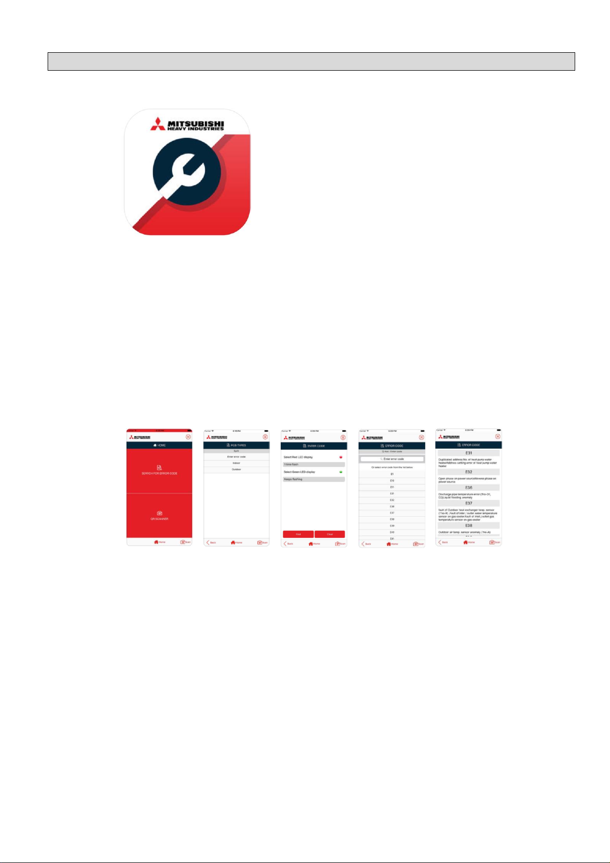
MHI e-service
DCSL Software Ltd
Free
Compatibility
Iphone or Ipad on IOS9.3 or later Android devices on 4.3 or later.
Screenshots
Description
MHI e-service is an application that enables users to make a quick search of the meaning
of error codes that may appear when there is a malfunction in "Mitsubishi Heavy Industries
Thermal Systems, Ltd" Air conditioning system, and the probable cause of the
malfunction.
In addition this application enables you to scan unit's QR code and search the meaning
of error codes depending on the model type.
The application covers "Mitsubishi Heavy Industries Thermal Systems, Ltd" Air conditioning
systems: Split (RAC & PAC), VRF, Q-ton & A2W.
The MHI e-service app is a free download available from Google Play for Android devices
(4.03 or later), or the Apple App Store for IOS devices (IOS9.3 or later).
MHI e-service app

WARNING
The information contained in this ‘Service Support Handbook’ is intended for use by
qualified service technicians familiar with safety procedures and equipped with the
proper tools and test instruments. Additionally, the information presented here is not a
replacement for, nor a substitute to the Manufacturers Technical Manuals.
MHI Air Conditioners contain pressurized refrigerants that are harmful to the atmosphere
so all refrigeration works must be performed by a qualified "F-Gas" registered person.
Please do not remove any covers, or attempt any repair or measurement on any MHI
LTD. product, unless you are suitably qualified and licensed to do so.
Repairs made by unqualified persons can result in hazards to you and others.
Technical Assistance is available Monday to Friday
between the hours of 08:00 and 17:00
on 03301 235 598
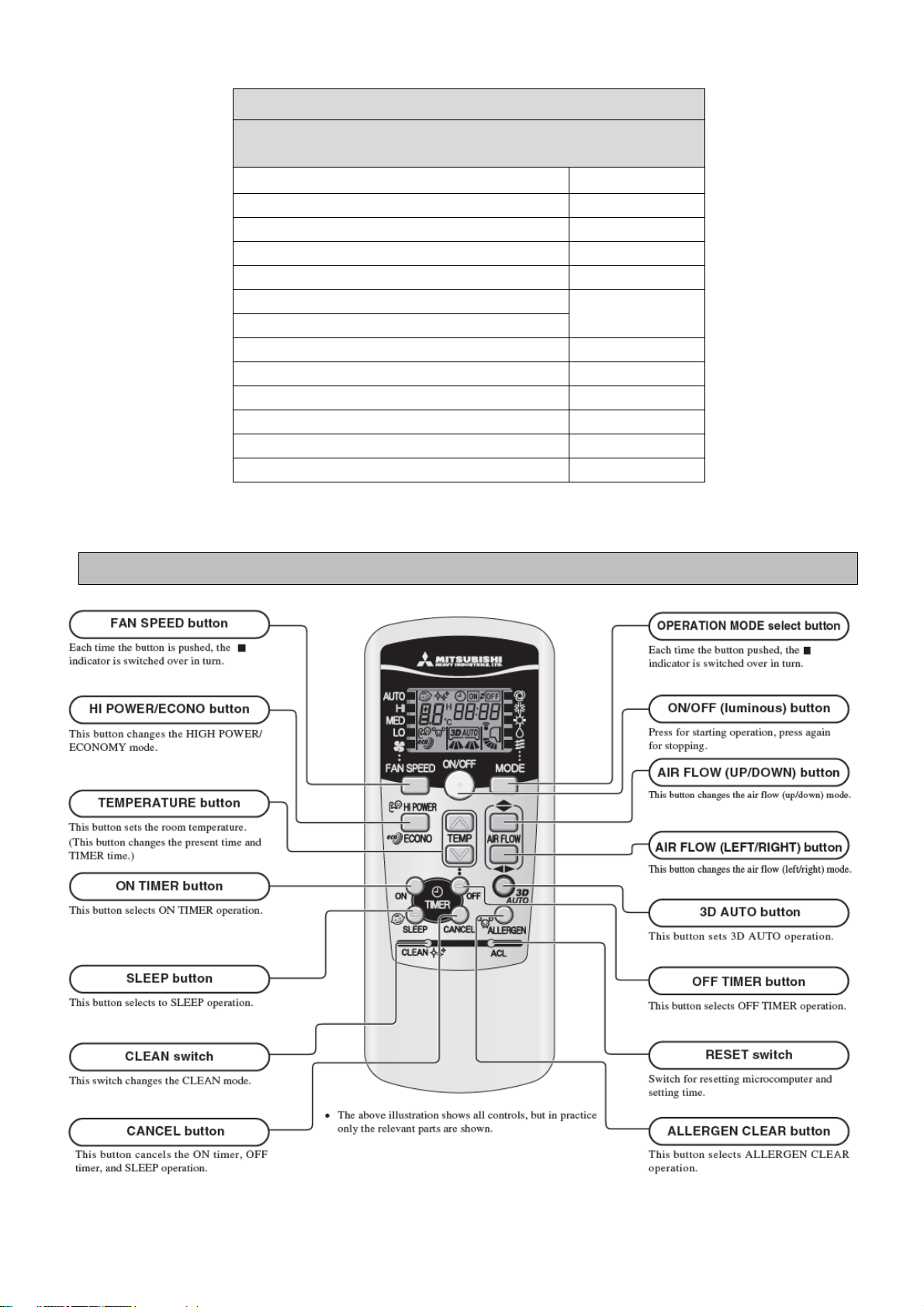
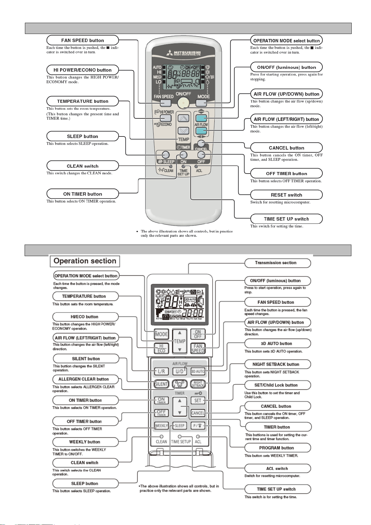
Hi-Wall Mounted Split Systems - Remote Controls of SRK
Before Proceeding to RAC Self Diagnosis Information,
ensure the correct Remote Control is being used.
Indoor Model
Remote Control
SRK--HC-S, HC-S1, HD-S, ZD-S, SKM--ZD-S
RMA502A001
SRK--HG-S
RKX502A007B
SRK--ZE-S, SRK--ZE-S1, SRK--ZR-S
RKW502A200D
SRK--ZFX-S, SRK--ZGX-S
RKW502A200B
SRK--ZG-S, ZHX-S, ZIX-S
RKX502A001C
SRK--ZJ-S, ZJ-S1, ZJX-S, ZJX-S1
SRK--ZM-S, SRK--ZMX-S, SRK--ZR-S
RLA502A701R
SRK--ZS-S
RLA502A701L
SRK--ZSX-S
RLA502A700K
SRF--ZMX-S
RLA502A700C
SRK--ZMP-S
RKX502A001P
SRK--ZSP-S
RKX502A007P
RKX502A001C
RKW502A200
RLA502A701R
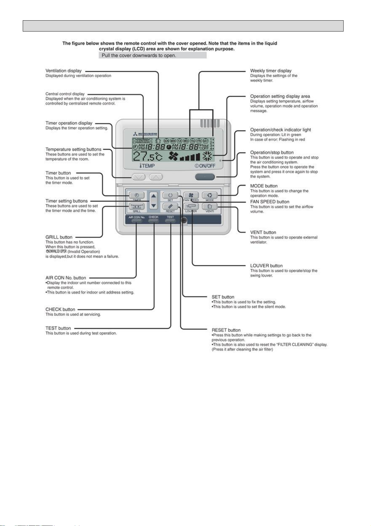
RC-E5 Layout
To access the RC-E5 Remote Controls Operation Data function, press the "CHECK" button on the MASTER remote control.
On 'Operation data' press the "SET" button.
If 'I/U No' is displayed select the unit number required, using the "/\" and "\/" buttons above the "CHECK" button, then
press the "SET" button
All navigation is carried out using the "/\" and "\/" buttons above the "CHECK" button.
RAC Unit
Compatibility
01
MODE
Current operation mode
ok
02
SET TEMP
°C
Set temperature
ok
03
RETURN AIR
°C
Return air sensor temperature
ok
04
SENSOR
°C
Remote control sensor temperature
ok
05
THI-R1
°C
Indoor heat exchanger sensor (on U bend)
ok
06
THI-R2
°C
Indoor heat exchanger sensor (on Capillary)
ok
07
THI-R3
°C
Indoor heat exchanger sensor (on suction header)
-
08
I/U FANSPEED
Indoor unit fan speed
-
09
DEMAND
Hz
Required frequency
-
10
ANSWER
Hz
Response frequency
-
11
I/U EEV
PULSE
Pulse rate of KX indoor unit expansion valve
-
12
TOTAL I/U RUN
Hr
Total running hours of the indoor unit
-
21
OUTDOOR
°C
Outdoor air temperature
ok
22
THO-R1
°C
Outdoor unit heat exchanger sensor
ok
23
THO-R2
°C
Outdoor unit heat exchanger sensor
-
24
COMP
Hz
Compressor frequency
ok
25
HP
MPa
High pressure (x10=Bar)
-
26
LP
Mpa
Low pressure (x10=Bar)
-
27
Td
°C
Discharge Pipe Temperature
ok
28
COMP BOTTOM
°C
Compressor base temperature
-
29
CT
Amp
Current
ok
30
TARGET SH
°C
Target Super Heat
-
31
SH
°C
Super Heat temperature
-
32
TDSH
°C
Compressor discharge pipe super heat
ok
33
PROTECTION No
Protection state number of the compressor
-
34
O/U FANSPEED
Outdoor unit fan speed
ok
35
63H1
63H1 High pressure switch on/off
-
36
DEFROST
Defrost control on/off
ok
37
TOTAL COMP RUN
Hr
Total running hours of compressor
-
38
O/U EEV1
PULSE
Pulse rate of the outdoor unit expansion valve EEVC
ok
39
O/U EEV2
PULSE
Pulse rate of the outdoor unit expansion valve EEVH
-
No. Contents of display
0 Normal
1 Discharge pipe temperature protection control
2 Discharge pipe temperature anomaly
3 Current safe control of inverter primary current
4 High pressure protection control
5 High pressure anomaly
6 Low pressure protection control
7 Low pressure anomaly
8 Anti-frost prevention control
9 Current cut
10 Power transistor protection control
11 Power transistor anomaly (Overheat)
12 Compression ratio control
13 14 Condensation prevention control
15 Current safe control of inverter secondary current
16 Stop by compressor rotor lock
17 Stop by compressor startup failure
Details of 33 Compressor Protection Status
RC-E5 OPERATION DATA
Touch panel control, which is operated by tapping the LCD screen with a finger, is employed for all functions except
1 On/Off switch, 2 Hi Power switch and 3 ECO switch.
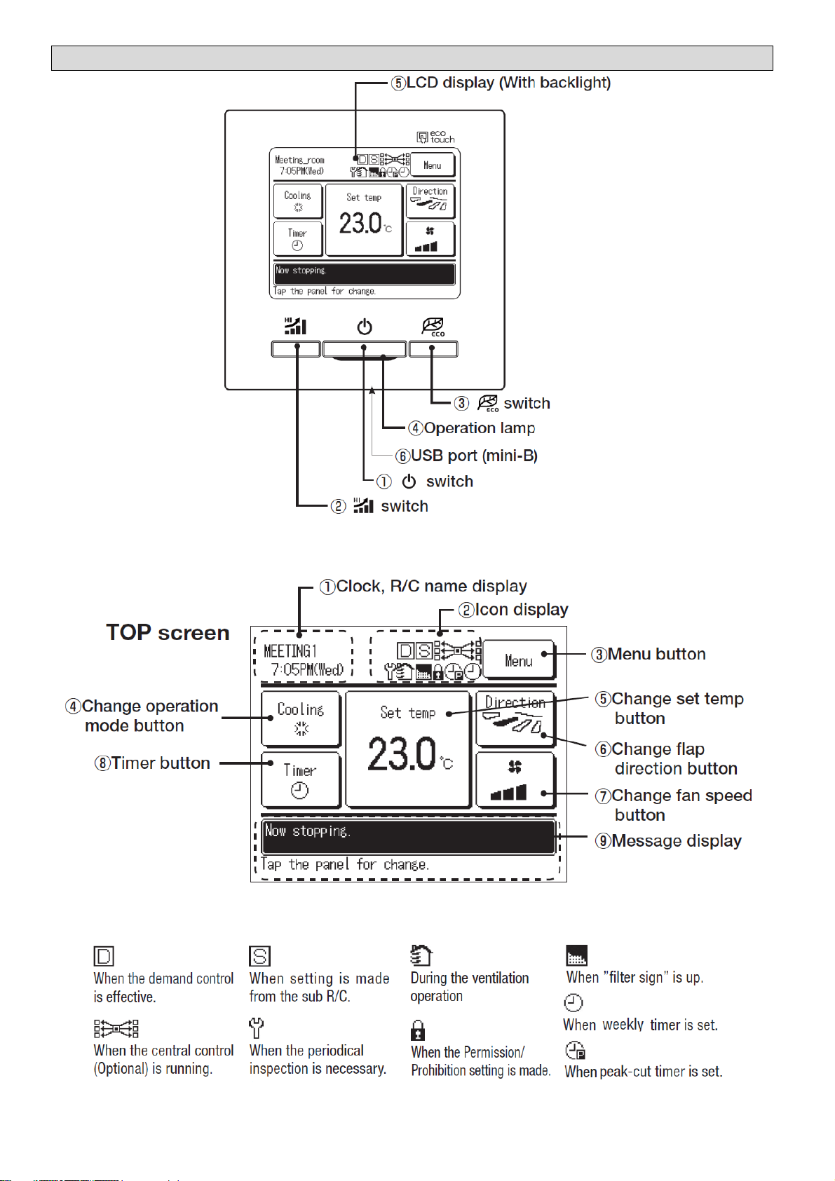
RC-EX1 & EX1A Layout
Touch panel control, which is operated by tapping the LCD screen with a finger, is employed for all functions except
1 On/Off switch, 2 Hi Power switch and 3 ECO switch.
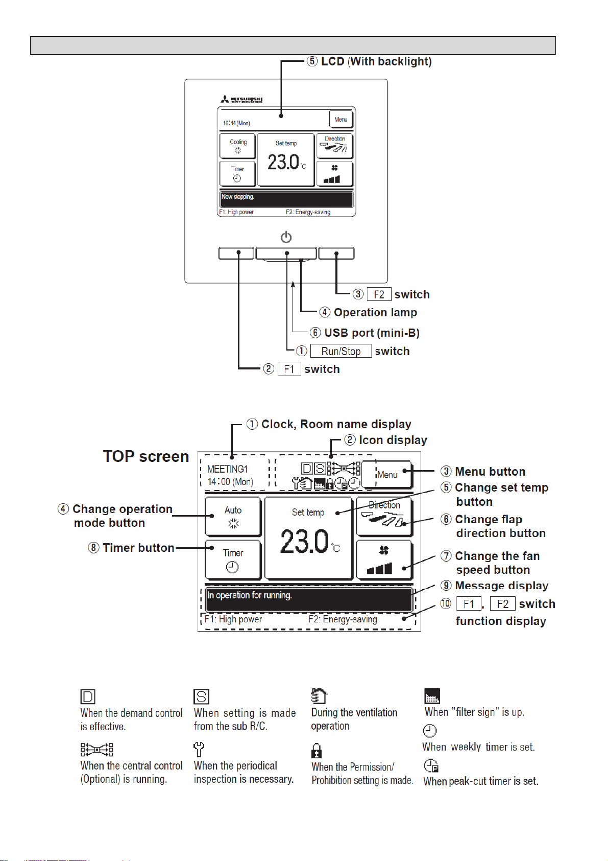
RC-EX3 Layout

To access the RC-EX Remote Controls Operation Data function, press MENU on the MASTER remote control Front Screen.
Then press NEXT followed by SERVICE (RC-EX3 only) and SERVICE & MAINTENANCE. Enter the service pass code, press SET
then press OPERATION DATA. You can then select the indoor unit you want to view.
RAC Unit
Compatibility
01
MODE
Current operation mode
ok
02
SET TEMP
°C
Set temperature
ok
03
RETURN AIR
°C
Return air sensor temperature
ok
04
SENSOR
°C
Remote control sensor temperature
ok
05
THI-R1
°C
Indoor heat exchanger sensor (on U bend)
ok
06
THI-R2
°C
Indoor heat exchanger sensor (on Capillary)
ok
07
THI-R3
°C
Indoor heat exchanger sensor (on suction header)
-
08
I/U FANSPEED
Indoor unit fan speed
-
09
DEMAND
Hz
Required frequency
-
10
ANSWER
Hz
Response frequency
-
11
I/U EEV
PULSE
Pulse rate of KX indoor unit expansion valve
-
12
TOTAL I/U RUN
Hr
Total running hours of the indoor unit
-
21
OUTDOOR
°C
Outdoor air temperature
ok
22
THO-R1
°C
Outdoor unit heat exchanger sensor
ok
23
THO-R2
°C
Outdoor unit heat exchanger sensor
-
24
COMP
Hz
Compressor frequency
ok
25
HP
MPa
High pressure (x10=Bar)
-
26
LP
Mpa
Low pressure (x10=Bar)
-
27
Td
°C
Discharge Pipe Temperature
ok
28
COMP BOTTOM
°C
Compressor base temperature
-
29
CT
Amp
Current
ok
30
TARGET SH
°C
Target Super Heat
-
31
SH
°C
Super Heat temperature
-
32
TDSH
°C
Compressor discharge pipe super heat
ok
33
PROTECTION No
Protection state number of the compressor
-
34
O/U FANSPEED
Outdoor unit fan speed
ok
35
63H1
63H1 High pressure switch on/off
-
36
DEFROST
Defrost control on/off
ok
37
TOTAL COMP RUN
Hr
Total running hours of compressor
-
38
O/U EEV1
PULSE
Pulse rate of the outdoor unit expansion valve EEVC
ok
39
O/U EEV2
PULSE
Pulse rate of the outdoor unit expansion valve EEVH
-
No. Contents of display
0 Normal
1 Discharge pipe temperature protection control
2 Discharge pipe temperature anomaly
3 Current safe control of inverter primary current
4 High pressure protection control
5 High pressure anomaly
6 Low pressure protection control
7 Low pressure anomaly
8 Anti-frost prevention control
9 Current cut
10 Power transistor protection control
11 Power transistor anomaly (Overheat)
12 Compression ratio control
13 14 Condensation prevention control
15 Current safe control of inverter secondary current
16 Stop by compressor rotor lock
17 Stop by compressor startup failure
Details of 33 Compressor Protection Status
RC-EX OPERATION DATA
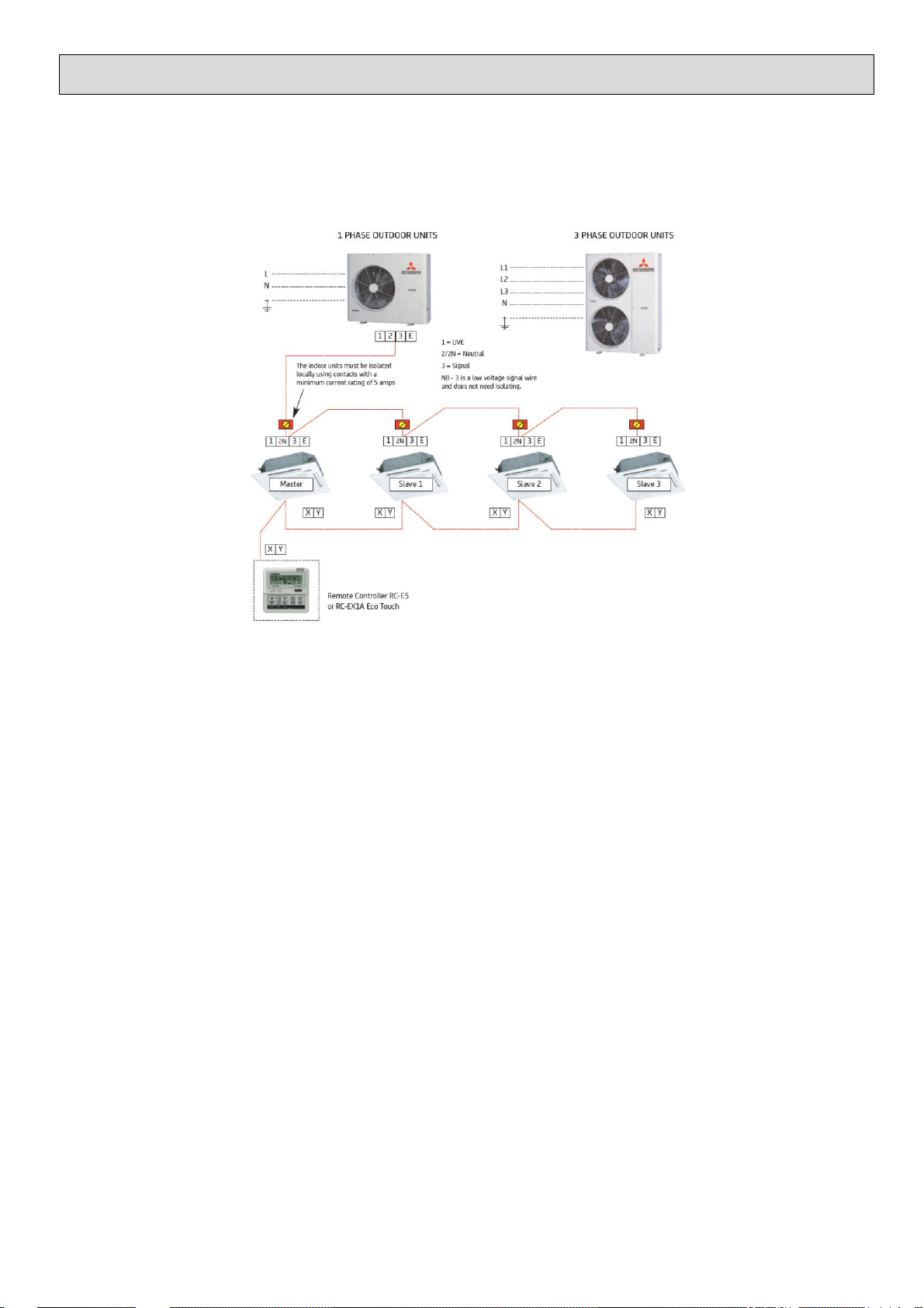
Master/ Slave and Group Settings
Master / Slave Settings
All split system indoor units are supplied set up as a master unit as default and this only needs changing when the system being
installed is a multisplit system, excluding SCM or KX systems, comprising of 2 to 4 RAC or PAC indoor units running off a
PAC single split outdoor unit. The remote control wires and all wires of the interconnecting cable go to each indoor unit
including the slave units.
When using RAC SRK indoor units, excluding ZMP/ZSP models, on a multisplit each indoor unit needs an SC-BIKN-E
interface to allow the installation of the wired remote control and setup of the master slave settings.
SYSTEM TYPE PAC Indoor Units SC-BIKN-E Interface
Unit SW5-1 SW5-2 SW3-1 SW3-2
Single Twin Triple Quad MASTER OFF OFF OFF OFF
Twin Triple Quad SLAVE 1 OFF ON OFF ON
Triple Quad SLAVE 2 ON OFF ON OFF
Quad SLAVE 3 ON ON ON ON
All indoor units on a multisplit system must be in the same space and operate off a single wired remote control as there is no
refrigerant control in the indoor units.
Group Settings
When multiple systems need to be controlled off a single RC-EX1A, RC-EX3 or RC-E5 wired remote control each system
needs to be given a different address. The system addressing is set on PAC unit indoor boards using SW2 or on RAC indoor
units via SW1 on the SC-BIKN-E interface. Upto 16 indoor units can be connected to a wired remote and that includes
multiplit systems using PAC outdoor units.
System Indoor Outdoor System Unit Group Address Master Slave
Unit Unit Type Switch Setting Switch #1 #2
1 FDT FDC Split Master SW2 0 SW5 OFF OFF
2 FDT FDC Quad Master SW2 1 SW5 OFF OFF
FDT Slave 1 SW2 1 SW5 OFF ON
FDT Slave 2 SW2 1 SW5 ON OFF
FDT Slave 3 SW2 1 SW5 ON ON
3 SRK FDC Twin Master SW1 2 SW3 OFF OFF
SRK Slave 1 SW1 2 SW3 OFF ON
4 FDUM FDC Split Master SW2 3 SW5 OFF OFF

Refrigerant Piping Information
RAC CURRENT MODELS
Model Precharged Maximum Maximum Vertical Factory Additional Pipe Sizes MCB
Piping Piping Piping Length (m) Charge Charge R410A Liquid Pipe Gas Pipe Rating
Length (m) Length (m) O/D Above I/D Above R410A (kg) per m (g/m) "" (mm) "" (mm) A
SRC25ZMP-S, 10 15 10 10 0.655 20 1/4" (6.35) 3/8" (9.52) 16
SRC35ZMP-S 15 15 10 10 0.810 N/A 1/4" (6.35) 3/8" (9.52) 16
SRC45ZMP-S 15 25 15 15 1.200 20 1/4" (6.35) 1/2" (12.7) 16
SRC25ZM-S 15 15 10 10 0.750 N/A 1/4" (6.35) 3/8" (9.52) 16
SRC35ZM-S 15 15 10 10 1.050 N/A 1/4" (6.35) 3/8" (9.52) 16
SRC50ZM-S 15 25 15 15 1.350 20 1/4" (6.35) 1/2" (12.7) 16
FDC100VNP 15 30 20 20 2.550 60 3/8" (9.52) 5/8" (15.88) 32
SRC20_35ZMX-S 15 15 10 10 1.200 N/A 1/4" (6.35) 3/8" (9.52) 16
SRC50_60ZMX-S 15 30 20 20 1.500 20 1/4" (6.35) 1/2" (12.7) 16
SRC63ZR-S 15 30 20 20 1.550 20 1/4" (6.35) 1/2" (12.7) 16
SRC71ZR-S 15 30 20 20 1.800 25 1/4" (6.35) 5/8" (15.88) 20
SRC80ZR-S 15 30 20 20 1.900 25 1/4" (6.35) 5/8" (15.88) 20
SRC20_25ZS-S 15 20 10 10 0.750 20 1/4" (6.35) 3/8" (9.52) 16
SRC35ZS-S 15 20 10 10 0.950 20 1/4" (6.35) 3/8" (9.52) 16
SRC50ZS-S 15 25 15 15 1.250 20 1/4" (6.35) 1/2" (12.7) 20
SCM Multi Splits
For SCM Systems the maximum one way piping length to an indoor unit is 25 metres.
Model Precharged Maximum Maximum Vertical Factory Additional Pipe Sizes MCB
Piping Piping Piping Length (m) Charge Charge R410A Liquid Pipe Gas Pipe Rating
Length (m) Length (m) O/D Above I/D Above R410A (kg) per m (g/m) "" (mm) "" (mm) A
SCM40ZS-S 30 30 15 15 1.900 N/A 2x 1/4" (6.35) 2x 3/8" (9.52) 25
SCM45ZS-S 30 30 15 15 1.900 N/A 2x 1/4" (6.35) 2x 3/8" (9.52) 25
SCM50ZS-S 40 40 15 15 2.500 N/A 3x 1/4" (6.35) 3x 3/8" (9.52) 25
SCM45ZM-S 30 30 15 15 2.000 N/A 2x 1/4" (6.35) 2x 3/8" (9.52) 25
SCM60ZM-S 40 40 15 15 2.500 N/A 3x 1/4" (6.35) 3x 3/8" (9.52) 25
SCM80ZM-S 40 70 20 20 3.150 20 4x 1/4" (6.35) 4x 3/8" (9.52) 25
SCM100_125ZM-S 50 90 20 20 6.000 20 5x 1/4" (6.35) 5x 3/8" (9.52) 32
PAC Splits - CURRENT MODELS
Model Precharged Maximum Maximum Vertical Factory Additional Pipe Sizes MCB
Piping Piping Piping Length (m) Charge Charge R410A Liquid Pipe Gas Pipe Rating
Length (m) Length (m) O/D Above I/D Above R410A (kg) per m (g/m) "" (mm) "" (mm) A(/ph)
FDC71VNP 15 30 20 20 1.600 20 1/4" (6.35) 1/2" (12.7) 20
FDC90VNP 15 30 20 20 2.100 20 1/4" (6.35) 5/8" (15.88) 20
FDC100VNP 15 30 20 20 2.550 60 3/8" (9.52) 5/8" (15.88) 32
FDC100VN 30 50 30 15 3.800 60 3/8" (9.52) 5/8" (15.88) 32
FDC125VN 30 50 30 15 3.800 60 3/8" (9.52) 5/8" (15.88) 32
FDC140VN 30 50 30 15 3.800 60 3/8" (9.52) 5/8" (15.88) 32
FDC71VNX 30 50 30 15 2.950 60 3/8" (9.52) 5/8" (15.88) 25
FDC100VNX 30 100 30 15 4.500 60 3/8" (9.52) 5/8" (15.88) 32
FDC125VNX 30 100 30 15 4.500 60 3/8" (9.52) 5/8" (15.88) 32
FDC140VNX 30 100 30 15 4.500 60 3/8" (9.52) 5/8" (15.88) 32
FDC100VS 30 50 30 15 3.800 60 3/8" (9.52) 5/8" (15.88) 20
FDC125VS 30 50 30 15 3.800 60 3/8" (9.52) 5/8" (15.88) 20
FDC140VS 30 50 30 15 3.800 60 3/8" (9.52) 5/8" (15.88) 20
FDC100VSX 30 100 30 15 4.500 60 3/8" (9.52) 5/8" (15.88) 20
FDC125VSX 30 100 30 15 4.500 60 3/8" (9.52) 5/8" (15.88) 20
FDC140VSX 30 100 30 15 4.500 60 3/8" (9.52) 5/8" (15.88) 20
FDC200VSA 30 70 30 15 5.600 60 3/8" (9.52) 7/8" (22.22) 32
FDC250VSA 30 70 30 15 7.200 120 1/2" (12.7) 1-1/8" (28.58) 32
Refrigerant Piping Information
Historic Models
Precharged Maximum Maximum Vertical Factory Additional Pipe Sizes
Piping Piping Piping Length (m) Charge Charge R410A Liquid Pipe Gas Pipe
Length (m) Length (m) O/D Above I/D Above R410A (kg) per m (g/m) "" (mm) "" (mm)
15 15 10 10 0.900 N/A 1/4" (6.35) 3/8" (9.52)
15 15 10 10 1.200 N/A 1/4" (6.35) 3/8" (9.52)
15 15 10 10 0.750 N/A 1/4" (6.35) 3/8" (9.52)
15 15 10 10 1.100 N/A 1/4" (6.35) 3/8" (9.52)
15 15 10 10 1.050 N/A 1/4" (6.35) 3/8" (9.52)
15 15 10 10 0.750 N/A 1/4" (6.35) 3/8" (9.52)
15 15 10 10 1.150 N/A 1/4" (6.35) 3/8" (9.52)
15 25 15 15 1.350 20 1/4" (6.35) 3/8" (9.52)
15 15 10 10 1.200 N/A 1/4" (6.35) 3/8" (9.52)
15 30 20 20 1.400 20 1/4" (6.35) 1/2" (12.7)
15 30 20 20 1.500 20 1/4" (6.35) 1/2" (12.7)
15 30 20 20 1.900 25 1/4" (6.35) 5/8" (15.88)
15 30 20 20 1.800 25 1/4" (6.35) 5/8" (15.88)
15 30 20 20 1.800 25 1/4" (6.35) 5/8" (15.88)
15 30 20 20 1.800 25 1/4" (6.35) 5/8" (15.88)
20 30 15 15 1.600 20 2x 1/4" (6.35) 2x 3/8" (9.52)
30 40 15 15 2.200 20 3x 1/4" (6.35) 3x 3/8" (9.52)
40 70 20 20 3.150 20 4x 1/4" (6.35) 4x 3/8" (9.52)
30 30 15 15 2.000 N/A 2x 1/4" (6.35) 2x 3/8" (9.52)
40 40 15 15 2.500 N/A 3x 1/4" (6.35) 3x 3/8" (9.52)
40 70 20 20 3.150 20 4x 1/4" (6.35) 4x 3/8" (9.52)
50 90 20 20 6.000 20 5x 1/4" (6.35) 5x 3/8" (9.52)
30 40 30 15 1.550 20 1/4" (6.35) 1/2" (12.7)
30 40 30 15 1.750 20 1/4" (6.35) 5/8" (15.88)
30 50 30 15 2.950 60 3/8" (9.52) 5/8" (15.88)
30 50 30 15 3.800 60 3/8" (9.52) 5/8" (15.88)
30 50 30 15 2.950 60 3/8" (9.52) 5/8" (15.88)
30 70 30 15 5.400 60 3/8" (9.52) 7/8" (22.22)
30 70 30 15 7.200 120 1/2" (12.7) 7/8" (22.22)
FDC71VN
FDC200VS
FDC250VS
SCM80ZG-S
SCM45ZJ-S
SCM60ZJ-S,S1
SCM80ZJ-S,S1
SCM100,125ZJ-S,S1
FDCVA151,201HEN
FDCVA251HEN
FDCVA302HENR,AR
FDCVA402_602HENR,AR
SRC20,25,35,ZIX,ZJX-S,ZJX-S1
SRC50,60ZFX,ZGX,ZHX,ZIX
SRC50,60ZJX-S
SRC63_71-S,S1
SRC63,71,80,ZK-S
SRC63ZM-S
SRC71_80ZM-S
SCM45ZG-S
SCM60ZG-S
Model
SRC20_25ZD,ZF,ZG
SRC20_325ZGX-S
SRC20,25ZJ-S
SRC35ZD,ZG
SRC35ZJ-S
SRC20ZJ-S1
SRC25,35ZJ-S1
SRC50ZD,ZG,ZJ-S,ZJ-S1
SRK
SRR/ SRF
SRC
Description of Trouble Possible Cause
Run Light
Timer
Light
Green Amber
Red LED
- - - E1 Error of wi red remote Broken wi re, fa ulty indoor P.C.B., faul ty control le r.
OFF Flas hing - E21 Li mit Switch error
Defe ctive limi t switch, ai r inlet pane l s et, I/D
control PCB
1x ON - - He at excha nger s ens or (1) error
Broken he at e xcha nger sensor (1) wire, poor
conne ction
2x ON - E7 Room temperature sens or
Broken room temperature s ens or wi re, poor
conne ction
2x 2x 7x E60 Rotor l ock
Fa ulty compressor, open pha se on compres sor,
faulty outdoor P.C.B.
3x ON - - He at excha nger s ens or (2) error
Broken he at e xcha nger sensor (2) wire, poor
conne ction
4x ON - E9 Drai n Fa ult
Float s witch a ctivated, faulty pump, faulty PCB,
faulty float s witch
5x ON 2x E47 Active Fil ter volta ge e rror Defe ctive Active Fi lter, incorrect power supply
6x ON - E16 I ndoor fan motor e rror Fa ult indoor fan motor, poor connecti on
7x ON 2x E57
Refri geration system prote ctive
control
Service valve clos ed, refrigerant i nsufficient
7x 1x 4x E40
Service valve (ga s s ide) cl osed,
defe ctive outdoor PCB
Output current of i nverter excee ds specifi cation
Fla shing 1x 8x E38 Outdoor ai r temp s ens or Broken s ensor wi re, poor connection
Fla shing 2x 8x E37 Outdoor heat excha nger s ens or Broken s ensor wi re, poor connecti on
Fla shing 4x 8x E39 Dis charge pipe sensor Broken s ensor wi re, poor connection
ON 1x 1x E42 Current Cut
Compressor locki ng, open pha se on compres sor
output, s hort ci rcuit on power transis tor, clos ed
service valve, EEV not opening
ON 2x 2x E59 Trouble of outdoor unit
Broken compre ssor wi re, broke n powe r trans is tor,
broken discharge s ensor wire/poor connection,
compress or bl ockage
ON 3x 3x E58 Current s afe stop
Overload protection, over cha rged, compres sor
locking
ON 4x 1x E51 Power Trans is tor error Faul ty power trans is tor
ON 5x 5x E36 Over heat of compres sor
Low on gas, faulty di scharge pipe senor, cl osed
service valve
ON 6x 6x E3 / E5 Error of s ignal tra nsmi ssi on
Defe ctive powe r suppl y, broken si gnal wire,
faulty indoor/outdoor P.C.B.
ON 7x ON E48 Fa ulty outdoor fa n motor Fa ulty condenser fa n motor, poor conne ction
ON Fla shing 2x E35 Cooling High Press ure Protection
Overload protection, over cha rged, broken
outdoor he at e xcha nger sensor wire, closed
service valve
Outdoor
Control
PCB,
Wired
Remote
Control
Inverter RAC
Outdoor Unit
ZD, ZE, ZE-S1, ZG, ZJ, ZJ-S1,ZM, ZR, ZS, ZFX, ZGX, ZHX, ZIX, ZJX, ZJX-S1,ZMX, ZSX
Indoor Unit Display
RAC FAULT CODES
ZD, ZE, ZE-S1, ZG, ZJ, ZJ-S1,ZM, ZMP, ZR, ZS, ZFX, ZGX, ZHX, ZIX, ZJX, ZJX-S1,ZMX, ZSX
ZIX, ZJX, ZJX-S1,ZMX
Inverter RAC
Indoor Unit
SRK ZJX-S, ZJX-S1 ZK-S
SRR
SRF
FDTC
FDUM
FDEN
SCM
Run Light
Timer
Light
Green Amber
Red LED
- - - E1
Error of wired remote Control
- - 1 E41
Power transistor overheat
- - 2 E40
High pressure error
- - 4 E45
Outd oor main or sub PCB
communication error
- - 8 E54
High pressure sensor
-
Flashing - E21 Limit switch error
1x ON OFF -
Indoor heat excha nger sensor (1)
error
2x ON OFF -
Room temperature sensor
2x 2x 7x E60
Rotor lock
3x ON OFF -
Heat ex chan ger sensor 2 error
4x ON OFF E9
Drain error
5x ON 2x E47
Activ e filter voltage error
6x ON OFF E16
Indoor fan motor error
7x ON 2x E57
Refrigerant cycle system protective
control
Flashing 1x 8x E38 Outdoor air temperature sensor
Flashing 2x 8x E37 Outdoor heat exchanger sensor
Flashing 4x 8x E39 Discharge pipe sensor
Flashing 5x 8x E53 Outdoor suction sensor
ON 1x x1 E42
Current Cut
ON 2x 2x E59
Trouble of outdoor unit
ON 3x 3x E58
Current safe stop
ON 4x 1x E51
Power transistor error
ON 5x 5x E36
Ov er heat of compressor
ON 6x 6x E5
Error of signal transmission
ON 7x Flashing E48
Outd oor fan motor or main PCB
ON Flashing 2x E35
Cooling High Pressure Protection
Faulty pow er transistor or sensor.
Outd oor sub or main PCB faulty, poor connection of wires
betw een outdoor PCBs
Faulty high pressure sensor, faulty control PCB.
Broken sensor wire, poor connection, faulty outdoor PCB
Broken sensor wire, poor connection, faulty outdoor sub
PCB
Faulty compressor, open pha se on compressor, faulty
outdoor P.C.B.
Defective limit switch, air inlet panel set, I/D control PCB
Faulty high pressure sensor, faulty control PCB, poor air
circulation.
Broken wire, faulty indoor P.C.B., faulty controller.
Defective Activ e Filter, incorrect power supply
Faulty indoor fan motor, poor connection
Closed serv ice v alve, insufficient refrigerant
Broken sensor wire, poor connection, faulty outdoor PCB
Broken sensor wire, poor connection, faulty outdoor PCB
Ov erload protection, ov er charged, broken outdoor heat
exchanger sensor wire, closed serv ice v alv e
Broken heat exchanger sensor (1) wire, poor connection
Broken room temperature sensor wire, poor connection
Broken heat exchanger sensor 3 wire, poor connection
Blocked drain, faulty float switch, faulty d rain pump
faulty inv erter PCB, faulty main PCB or faulty fan motor
Low on gas, faulty discharge pipe senor, closed service
v alv e
Defective power supply, broken signal wire, faulty
indoor/outdoor P.C.B.
Faulty condenser fan motor or faulty main P CB
Compressor locking, open phase on compressor output,
short circuit on power transistor, closed service v alv e
Broken compressor wire, broken power transistor, broken
discharge sensor wire or poor connection, compressor
Ov erload protection, ov er charged, compressor locking
Possible Cause
Description of Trouble
Inverter Mul ti
Outdoor
ZJ-S, ZJ-S1, ZM-S
Indoor Unit Display
Outdoor
Control
PCB,
Wired
Remote
Control
ZJ-S,ZJ-S1,ZM-S,ZMX-S
ZJ-S
ZJX-S, ZJX-S1,ZMX-S
VD,VF, VF/1
VF, VF/1
VD, VF, VF/1
Inverter Multi
Indoor
RAC MULTISPLIT FAULT CODES - Current and Previous Models
 Loading...