

Mitsubishi Heavy Industries RCN-E1R Installation Manual
PFA012D620
WIRELESS REMOTE CONTROLLER INSTALLATION MANUAL
WARNING
Fasten the wiring to the terminal securely and hold the cable securely so as not to apply unexpected stress on the terminal.
Loose connection or hold will cause abnormal heat generation or fire.
Make sure the power supply is turned off when electric wiring work.
Otherwise, electric shock, malfunction and improper running may occur.
CAUTION
Install a receiver unit where it is not exposed to direct sunrays or intense light from lighting fixtures.
1
Accessories
Please make sure that you have all of the following accessories.
Remoto controller holder
1
2
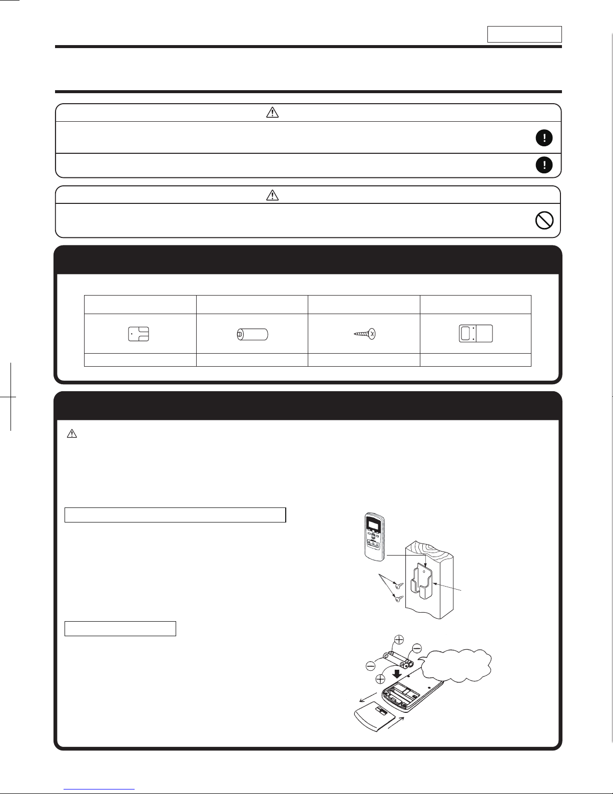
Installation of the controller holder
CAUTION DO NOT install it on the following places.
1. Places exposed to direct sunlight
3. Places near heat devices
5. High humidity places
Installation tips for the remote controller holder
• Adjust and keep the holder up right.
• Tighten the screw to the end to avoid scratching the
remote controller.
• DO NOT attach the holder on plaster wall.
AAA dry cell battery (RO3)
2
2. Hot surface or cold surface enough to generate condensation
4. Places exposed to oil mist or steam directly.
6. Uneven surface
Wood screw for holder
2
Wood screw
Wireless remote controller
1
Holder for
remote controller
How to insert batteries
1
Detach the back lid.
2
Insert the batteries. (two AAA batteries)
3
Reattach the back lid.
Ensure the correct
polarity when
inserting.
1
3
FDEN
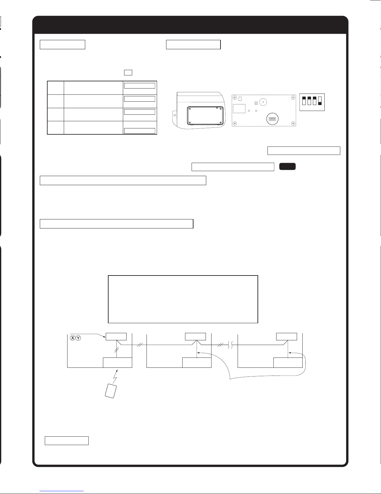
Setting on site
PCB on the receiver has the following
switches to set the function.
Default setting is shown with mark.
Prevents interference
SW1
during plural setting
Recei
SW2
setting
Buzzer valid/Invalid
SW3
Auto restart
SW4
ver master/slave
ON : Normal (1ch)
OFF : Customized (2ch)
ON :
Master
OFF :
Sl
ave
ON :
Valid
OFF :
Invalid
ON :
Valid
OFF :
Invalid
To change setting
1. Remove the front panel.
2. Remove four screws located on the back of the receiver and
detach the board.
3. Change the setting by the switch on PCB.
SW1
1
Switch
Receiver Backside
4.
When switch 1 is turned to off position, change the wireless remote controller setting.
2 3 4
Default settings
(For the method of changing the setting, refer to Setting to avoid mixed communication
on page 4)
Refer to Wireless remote controller unit operation distance of 3 FDEN in case of plural setting.
Master/Slave setting when using plural remote controllers
Up to two receiver or wired remote controller can be installed in one indoor unit group.
When two receivers or wired remote controller are used, it is necessary to change SW on the PCB to set it as
slave.
Control plural indoor units with one remote controller
ON
OFF
Up to 16 indoor units can be connected.
1
Connect indoor units with each other with 2-core wires. As for size, refer to the following note.
2
The receiver wires must be connected only with the indoor unit that will be operated by the remote
controller directly.
3
Set the indoor unit address with SW2 on the indoor unit PCB from [0] to [F] so as not to duplicate.
Restrictions on the thickness and length of wire
(Maximun total extension 600m.)
S
W
W
W
W
Terminal block
Indoor unit (1)
Address (0)
Wireless
remote control unit
tandard Within 100m x 0.3 mm2
ithin 200m x 0.5 mm2
ithin 300m x 0.75 mm2
ithin 400m x 1.25 mm2
ithin 600m x 2.0 mm2
Indoor unit (2)
Address (1)
Receiver wires must be connected for one unit
only and leave other indoor units with open
connectors.
Indoor unit (16)
Address (F)
ReceiverReceiverReceiver
ATTENTION
In a system configured as shown above, up to two receivers are usable. If two receivers are used, it is
necessary to designate one of them as a slave by setting SW2. (For the method of changing the setting, refer to
Setting on site .) Since other receivers are not usable, do not couple the connectors for them. (Unless the
connector is coupled for a receiver, the LED will not be able to make any indication)
Continuation on next page
2
 Loading...