

Mitsubishi Heavy Industries HSB60, FDCW60VNX-APT300, HMK60, RC-HY20, RC-HY40 Installation Manual
INSTALLATION MANUAL
MITSUBISHI HEAVY INDUSTRIES
Air to Water Heat Pump
H y drolution (HM)
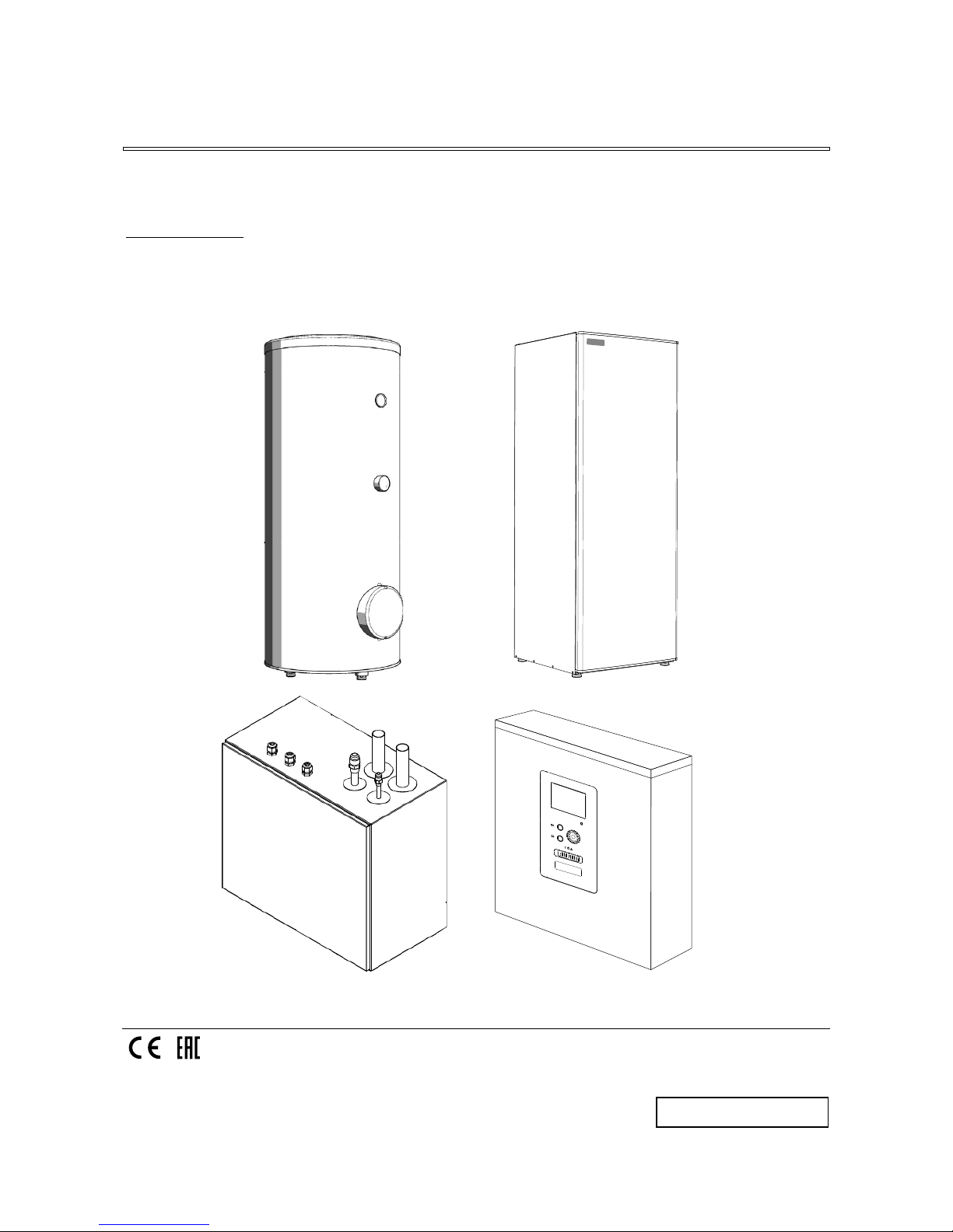
HSB60/HMK60/FDCW60VNX-A
PT300/RC-HY20/40
P
SC012D085BS
English:Original instruction
This heat pump complies with EMC Directive 2004/108/
EC (replaced by 2014/30/EU on 20/4/2016), LV Directive
2006/95/EC (replaced by 2014/35/EU on 20/4/2016).
CE marking is applicable to the area of 50 Hz power supply.
HK 200S
1
2
1
Safety precautions
2
General information for installer
7
Over view and design
7
Transport and storage
10
Supplied components
10
Assembly
10
Hanging indoor unit
12
Hanging control unit
12
Dimensioning expansion vessel
13
Recommended installation order
13
Pipe installation
14
General
14
Installation diagram
14
HSB60
14
HMK60
15
System requirements
16
Overflow valve
16
Pump capacity diagram
16
Pressure drop in indoor unit
1
7
Dimensions and pipe connections
1
7
HSB60
1
7
HMK60
17
PT300
18
Water circuit
19
Connection to heating system
19
Connection to hot water heater
19
Housing disassembly of tank unit
19
Connecting hot water tank to indoor unit
20
Connecting hot water tank to water main
21
Hot water circulation circuit
22
Connection of external heat source
23
Refrigerant circuit
23
Connecting refrigerant pipes
23
Piping insulation
23
Drain connection
23
Dockings
24
Electrical installation
29
General
29
Electrical components
30
Accessibility, electrical connection for controller
32
Cable lock
34
Connection
34
<HSB60>
34
Power supply
34
Connection between indoor and outdoor unit
34
Connection between indoor unit and controller
35
Cascade connection setting
35
Recommended fuse size for HSB60
35
Recommended cable size for HSB60
35
<HMK60>
35
Circuit breaker
35
Power supply
35
Connection between indoor and outdoor unit
36
Connection between indoor unit and controller
36
Recommended fuse size for HMK60
36
Recommended cable size for HMK60
35
<RC-HY20/40>
36
Power supply
36
Connection between controller and indoor unit
37
HSB60 with RC-HY20
37
HSB60 with RC-HY40
37
HMK60 with RC-HY20
37
HMK60 with RC-HY40
37
Connection between controller and circulation pump (GP12) 38
HSB60 with RC-HY20
38
HSB60 with RC-HY40
38
HMK60 with RC-HY20
39
HMK60 with RC-HY40
39
Connection between controller and 3-way valve (QN10/QN12) 40
HSB60 with RC-HY20
40
HSB60 with RC-HY40
40
HMK60 with RC-HY20
41
HMK60 with RC-HY40
41
Connection between controller and sensors
42
RC-HY20 with HSB60
42
RC-HY20 with HMK60
43
RC-HY40 with HSB60
45
RC-HY40 with HMK60
46
Optional connections
48
RC-HY20
48
Room sensor BT50
48
Step controlled additional heat
48
Connection example with HMK60
49
Relay output for emergency mode
49
Connection example with HMK60
50
External circulation pump
50
AUX inputs/outputs
50
myUpway™
52
RC-HY40
53
Load monitor
53
Room sensor BT50
53
Step controlled additional heat
53
Relay output for emergency mode
53
External circulation pump
53
AUX inputs/outputs
54
myUpway™
55
Commissioning and adjusting
56
Preparation
56
Filling and venting
56
Hot water tank
56
Climate system
56
Inspection of installation
56
Start-up and inspection
57
Before start-up
57
Commissioning with heat pump
57
Commissioning with additional heater only
57
3-way valve operation check
57
AUX function check
57
Cooling mode
57
Cleaning particle filter
57
Secondary adjustment
57
Start guide
58
Heating/cooling curve setting
59
Hot water circulation setting
60
SG ready
61
Control
62
Display unit
62
Menu system
63
Menu list
66
Menu 1 – Indoor climate
66
Menu 2 – Hot water
66
Menu 3 – Info
66
Menu 4 – My system
66
Menu 5 – Service
67
Service
75
Disturbances in comfort
78
Manage alarm
78
Troubleshooting
78
Additional heating only
79
Alarm list
80
Accessories
83
Technical data
84
Dimensions and setting-out coordinates
84
Electrical circuit diagram
85
Table of Contents
2
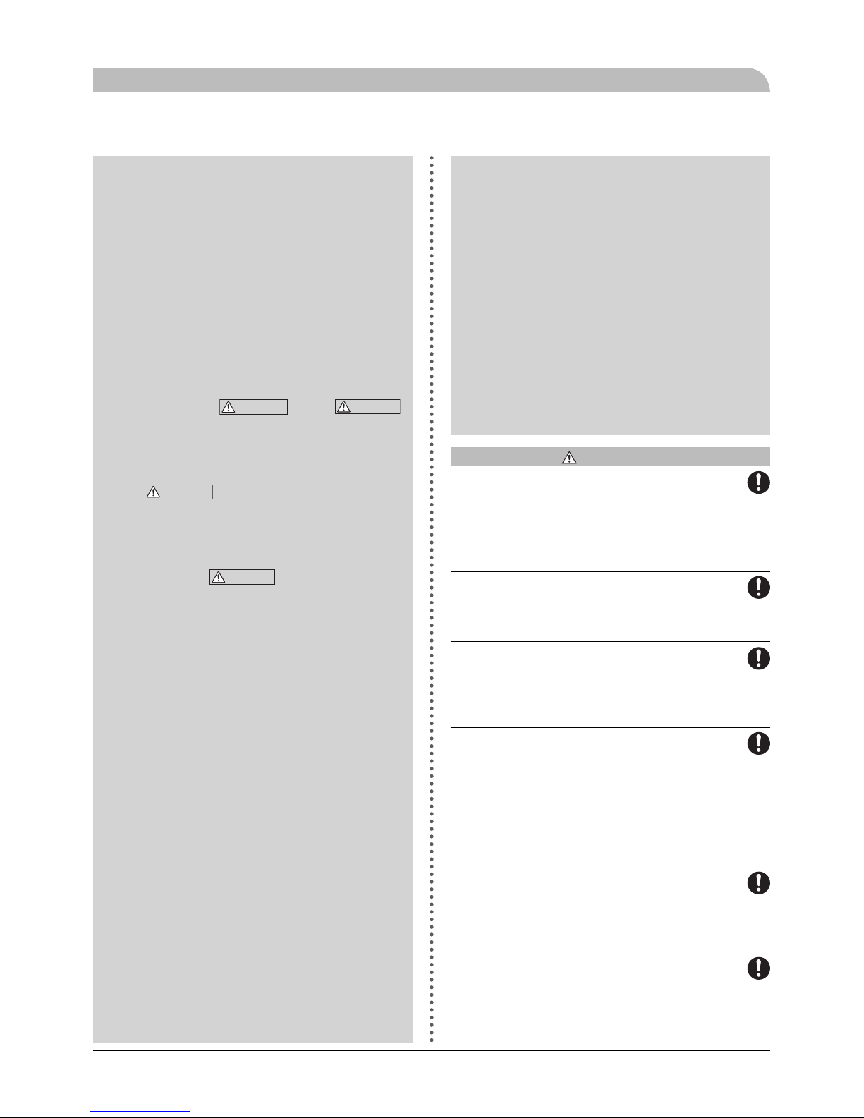
Safety precautions
Safety precautions
When installing the unit, be sure to check
whether the selection of installation
place, power supply specifications,
usage limitation (piping length, height
differences between indoor and outdoor
units, power supply voltage and etc.) and
installation spaces.
We recommend you to read this
“SAFETY PRECAUTIONS” carefully
before installation in order to gain full
advantage of the functions of the unit
and to avoid malfunction due to
mishandling.
The precautions described below are
divided into
WARNING
and
CAUTION
.
The matters with possibilities leading
to serious consequences such as
death or serious personal injury due
to erroneous handling are listed in
the
WARNING
and the matters with
possibilities leading to personal injury
or damage of the unit due to erroneous
handling including probability leading to
serious consequences in some cases
are listed in
CAUTION
. These are very
important precautions for safety. Be
sure to observe all of them without fail.
Be sure to confirm no anomaly on the
equipment by commissioning after
completed installation and explain the
operating methods as well as the
maintenance methods of this equipment
to the user according to the owner’s
manual.
Keep the installation manual together
with owner’s manual at a place where
any user can read at any time. Moreover
if necessary, ask to hand them to a new
user.
This heat pump complies with EMC
Directive 2014/30/EU.
This appliance is designed for use in a
home environment and can be used by
children aged from 8 years and above and
persons with reduced physical, sensory or
mental capabilities or lack of experience
and knowledge if they have been given
supervision or instruction concerning use
of the appliance in a safe way and
understand the hazards involved. Children
WARNING
Installation must be carried out by
the qualified installer.
If you install the system by yourself, it may cause
serious trouble such as water leaks, electric
shocks, fire and personal injury, as a result of a
system malfunction.
Install the system in full accordance
with the instruction manual.
Incorrect installation may cause bursts, personal
injury, water leaks, electric shocks and fi re.
Use the original accessories and the
specified components for installation.
If parts other than those prescribed by us are used,
It may cause water leaks, electric shocks, fi re and
personal injury.
When installing in small rooms, take
prevention measures not to exceed
the density limit of refrigerant in the
event of leakage.
Consult the expert about prevention measures. If
the density of refrigerant exceeds the limit in the
event of leakage, lack of oxygen can occur, which
can cause serious accidents.
Ventilate the working area well in the
event of refrigerant leakage during
installation.
If the refrigerant comes into contact with naked
fl ames, poisonous gas is produced.
After completed installation, check that
no refrigerant leaks from the system.
If refrigerant leaks into the room and comes into
contact with an oven or other hot surface, poisonous
gas is produced.
shall not play with the appliance. Cleaning
and user maintenance shall not be made
by children without supervision.
This in accordance to applicable parts of
the low voltage directive 2014/35/EU, LVD.
This appliance is also intended for use by
experts or trained users in shops, hotels,
light industry, on farms and in similar
environments. This in accordance to
applicable parts of the machinery directive
2006/42/EC.
CE marking is applicable to the area of 50
Hz power supply.
The emission sound pressure level from
each Indoor and Outdoor unit is under 70
dB(A).
3
the box. Install the service panel correctly.
Incorrect installation may result in overheating
and fi re.
Do not perform brazing work in the
airtight room.
It can cause lack of oxygen.
Use the prescribed pipes, flare nuts
and tools for R410A.
Using existing parts (for R22 or R407C) can
cause the unit failure and serious accidents due to
burst of the refrigerant circuit.
Tighten the flare nut by using double
spanners and torque wrench according
to prescribed method. Be sure not to
tighten the flare nut too much.
Loose fl are connection or damage on the fl are part
by tightening with excess torque can cause burst
or refrigerant leaks which may result in lack of
oxygen.
Do not open the service valves for
liquid line and gas line until completed
refrigerant piping work, air tightness
test and evacuation.
If the compressor is operated in state of opening
service valves before completed connection of
refrigerant piping work, air can be sucked into
refrigerant circuit, which can cause bust or
personal injury due to anomalously high pressure
in the refrigerant.
Do not put the drainage pipe directly into
drainage channels where poisonous
gases such as sulphide gas can occur.
Poisonous gases will fl ow into the room through
drainage pipe and seriously affect the user’s
health and safety.
Only use prescribed optional parts.
The installation must be carried out by
the qualified installer.
If you install the system by yourself, it can cause
serious trouble such as water leaks, electric
shocks, fi re.
Do not run the unit with removed panels
or protections
Touching rotating equipments, hot surfaces or
high voltage parts can cause personal injury due
to entrapment, burn or electric shocks.
Be sure to fix up the service panels.
Incorrect fi xing can cause electric shocks or
fi re due to intrusion of dust or water.
Do not perform any repairs or modifications by yourself. Consult the dealer
if the unit requires repair.
If you repair or modify the unit, it can cause water
Safety precautions
Hang up the unit at the specified points
with ropes which can support the
weight in lifting for portage. And to
avoid jolting out of alignment, be sure to
hang up the unit at 4-point support.
An improper manner of portage such as 3-point
support can cause death or serious personal injury
due to falling of the unit.
Install the unit in a location with good
support.
Unsuitable installation locations can cause the
unit to fall and cause material damage and
personal injury.
Ensure the unit is stable when installed,
so that it can withstand earthquakes
and strong winds.
Unsuitable installation locations can cause the
unit to fall and cause material damage and
personal injury.
Ensure that no air enters in the refrigerant circuit when the unit is installed
and removed.
If air enters in the refrigerant circuit, the pressure
in the refrigerant circuit becomes too high, which
can cause burst and personal injury.
The electrical installation must be
carried out by the qualified electrician
in accordance with “the norm for
electrical work” and “national wiring
regulation”, and the system must be
connected to the dedicated circuit.
Power supply with insufficient capacity and
incorrect function done by improper work can
cause electric shocks and fi re.
Be sure to shut off the power before
starting electrical work.
Failure to shut off the power can cause electric
shocks, unit failure or incorrect function of
equipment.
Be sure to use the cables conformed
to safety standard and cable ampacity
for power distribution work.
Unconformable cables can cause electric leak,
anomalous heat production or fi re.
Use the prescribed cables for electrical
connection, tighten the cables securely
in terminal block and relieve the
cables correctly to prevent overloading the
terminal blocks.
Loose connections or cable mountings can cause
anomalous heat production or fi re.
Arrange the wiring in the control box so
that it cannot be pushed up further into
4
leaks, electric shocks or fi re.
Do not perform any change of protective device itself or its setup condition
The forced operation by short-circuiting protective
device of pressure switch and temperature
controller or the use of non specified component
can cause fi re or burst.
Be sure to switch off the power supply
in the event of installation, inspection
or servicing.
If the power supply is not shut off , there is a risk
of electric shocks, unit failure or personal injury
due to the unexpected start of fan.
Consult the dealer or an expert regarding removal of the unit.
Incorrect installation can cause water leaks,
electric shocks or fi re.
Stop the compressor before disconnecting refrigerant pipes in case of pump
down operation.
If disconnecting refrigerant pipes in state of
opening service valves before compressor
stopping, air can be sucked, which can cause burst
or personal injury due to anomalously high
pressure in the refrigerant circuit.
CAUTION
Carry out the electrical work for ground
lead with care.
Do not connect the ground lead to the gas line,
water line, lightning conductor or telephone line’s
ground lead. Incorrect grounding can cause unit
faults such as electric shocks due to shortcircuiting.
Use the circuit breaker with sufficient
breaking capacity.
If the breaker does not have sufficient breaking
capacity, it can cause the unit malfunction and
fi re.
Earth leakage breaker must be installed.
If the earth leakage breaker is not installed, it can
cause electric shocks.
Do not use any materials other than a
fuse with the correct rating in the
location where fuses are to be used.
Connecting the circuit with copper wire or other
metal thread can cause unit failure and fi re.
Do not install the unit near the location
where leakage of combustible gases
can occur.
If leaked gases accumulate around the unit, it can
cause fi re.
Do not install the unit where corrosive
gas (such as sulfurous acid gas etc.) or
combustible gas (such as thinner and
petroleum gases) can accumulate or collect,
or where volatile combustible substances
are handled.
Corrosive gas can cause corrosion of heat
exchanger, breakage of plastic parts and etc. And
combustible gas can cause fi re.
Secure a space for installation, inspection and maintenance specified in the
manual.
Insufficient space can result in accident such as
personal injury due to falling from the installation
place.
When the outdoor unit is installed on a
roof or a high place, provide permanent
ladders and handrails along the access
route and fences and handrails around the
outdoor unit.
If safety facilities are not provided, it can cause
personal injury due to falling from the installation
place.
Do not use the indoor unit at the place
where water splashes may occur.
Since the indoor unit is not waterproof, it
can cause electric shocks and fi re.
Do not install or use the system close
to the equipment that generates electromagnetic fields or high frequency
harmonics.
Equipment such as inverters, standby generators,
medical high frequency equipments and
telecommunication equipments can affect the
system, and cause malfunctions and breakdowns.
The system can also aff ect medical equipment and
telecommunication equipment, and obstruct its
function or cause jamming.
Do not install the outdoor unit in a
location where insects and small animals
can inhabit.
Insects and small animals can enter the electric
parts and cause damage or fi re. Instruct the user to
keep the surroundings clean.
Do not use the base flame for outdoor
unit which is corroded or damaged due
to long periods of operation.
Using an old and damage base flame can cause
the unit falling down and cause personal injury.
Do not install the unit in the locations
listed below.
Locations where carbon fi ber, metal powder or
Safety precautions
5
any powder is fl oating.
Locations where any substances that can aff ect
the unit such as sulphide gas, chloride gas, acid
and alkaline can occur.
Vehicles and ships.
Locations where cosmetic or special sprays are
often used.
Locations with direct exposure of oil mist and
steam such as kitchen and machine plant.
Locations where any machines which generate
high frequency harmonics are used.
Locations with salty atmospheres such as
coastlines.
Locations with heavy snow (If installed, be sure
to provide base fl ame and snow hood mentioned
in the manual).
Locations where the unit is exposed to chimney
smoke.
Locations at high altitude (more than 1000m
high).
Locations with ammonic atmospheres.
Locations where heat radiation from other heat
source can aff ect the unit.
Locations without good air circulation.
Locations with any obstacles which can prevent
inlet and outlet air of the unit.
Locations where short circuit of air can occur (in
case of multiple units installation).
Locations where strong air blows against the air
outlet of outdoor unit.
It can cause remarkable decrease in performance,
corrosion and damage of components,
malfunction and fi re.
Do not install the outdoor unit in the
locations listed below.
Locations where discharged hot air or operating
sound of the outdoor unit can bother
neighborhood.
Locations where outlet air of the outdoor unit
blows directly to plants.
Locations where vibration can be amplifi ed and
transmitted due to insufficient strength of
structure.
Locations where vibration and operation sound
generated by the outdoor unit can affect
seriously. (on the wall or at the place near bed
room)
Locations where an equipment aff ected by high
harmonics is placed. (TV set or radio receiver is
placed within 5m)
Locations where drainage cannot run off safely.
It can aff ect surrounding environment and cause a
claim.
Do not install the remote controller at
the direct sunlight.
It can cause malfunction or deformation of the
remote controller.
Do not use the unit for special purposes
such as storing foods, cooling precision
instruments and preservation of
animals, plants or art.
It can cause the damage of the items.
Take care when carrying the unit by
hand.
If the unit weights more than 20kg, it must be
carried by two or more persons. Do not carry by
the plastic straps, always use the carry handle
when carrying the unit by hand. Use gloves to
minimize the risk of cuts by the aluminum fi ns.
Dispose of any packing materials correctly.
Any remaining packing materials can cause
personal injury as it contains nails and wood. And
to avoid danger of suff ocation, be sure to keep the
plastic wrapper away from children and to dispose
after tear it up.
Pay attention not to damage the drain
pan by weld spatter when welding
work is done near the indoor unit.
If weld spatter entered into the indoor unit during
welding work, it can cause pin-hole in drain pan
and result in water leakage. To prevent such
damage, keep the indoor unit in its packing or
cover it.
Be sure to insulate the refrigerant pipes
so as not to condense the ambient air
moisture on them.
Insufficient insulation can cause condensation,
which can lead to moisture damage on the ceiling,
fl oor, furniture and any other valuables.
Be sure to perform air tightness test
by pressurizing with nitrogen gas after
completed refrigerant piping work.
If the density of refrigerant exceeds the limit in
the event of refrigerant leakage in the small room,
lack of oxygen can occur, which can cause serious
accidents.
Do not touch any buttons with wet hands.
It can cause electric shocks.
Do not shut off the power supply immediately after stopping the operation.
Wait at least 5 minutes, otherwise there is a risk
of water leakage or breakdown.
Do not control the system with main
power switch.
It can cause fi re or water leakage. In addition, the
Safety precautions

6
Safety precautions
fan can start unexpectedly, which can cause
personal injury.
Do not touch any refrigerant pipes
when the system is in operation.
During operation the refrigerant pipes become
extremely hot or extremely cold depending the
operating condition, and it can cause burn injury
or frost injury.
Notabilia for units designed for R410A
Only use R410A refrigerant. R410A is the
refrigerant whose pressure is 1.6 times as high as
that of conventional refrigerant.
The size of charging port of service valve and
check joint for R410A are altered from that for
conventional refrigerant in order to prevent the
system being charged with the incorrect
refrigerant by mistake. And the protruding
dimension of pipe for flare processing and flare
nut size for R410A are also altered from that for
conventional refrigerant in order to reinforce
strength against the pressure for R410A.
Accordingly the dedicated tools for R410A listed
in the below mentioned table should be prepared
for installation and servicing.
Dedicated tools for R410A
a) Gauge manifold
b) Charge hose
c) Electronic scale for refrigerant charge
d) Torque wrench
e) Flare tool
f) Protrusion control gauge for copper pipe
g) Vacuum pump adapter
h) Gas leak detector
Do not use charging cylinder. Using charging
cylinder may alter the composition of refrigerant,
which results in making the performance of the
system worse.
Refrigerant must be charged always in liquid state
from the bottle.
7
General information for the installer
General information for installer
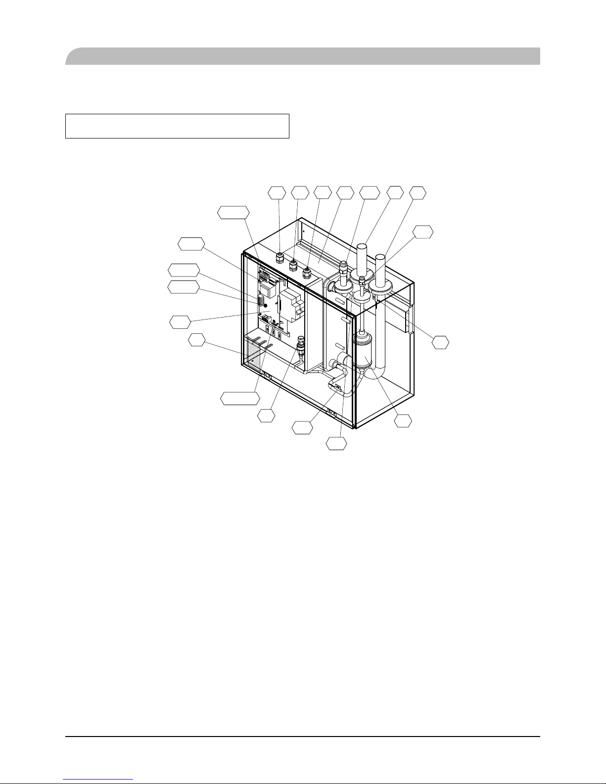
Over view and design
HSB60
XL1
XL2
XL1 3
XL14
HZ2
EP2
PF3
UB1
UB2
UB3
BT15
BT3
BP4
AA2 3
AA23-X100
AA2 3 - X4
AA23-S3
A23-F3
AA2 3 - X1
BT12
Pipe connections
XL1(Red mark) Climate system supply
XL2 (Blue mark) Climate system return
XL14 Connection, gas line
XL13 Connection, liquid line
Valves etc.
EP2 Heat exchanger
HQ1 Particle fi lter (supplied)
HZ2 Drying fi lter
Electrical components
AA23 Communication board
AA23-F3 Fuse for external heating cable
AA23-S3 DIP switch, addressing of outdoor unit
AA23-X1 Terminal block, incoming supply, connection
of KVR
AA23-X4 Terminal block, communication with indoor
module / control module
AA23-X100 Terminal block, communication outdoor
module
For outdoor unit installation information, see Installation
manual for Outdoor unit.
Sensor, thermostats
BP4 Pressure sensor, high pressure
BT3 Temperature sensor, heating medium, return
BT12 Temperature sensor, condenser, supply
BT15 Temperature sensor, fl uid pipe
Miscellaneous
UB1 Cable gland
UB2 Cable gland
UB3 Cable gland
8
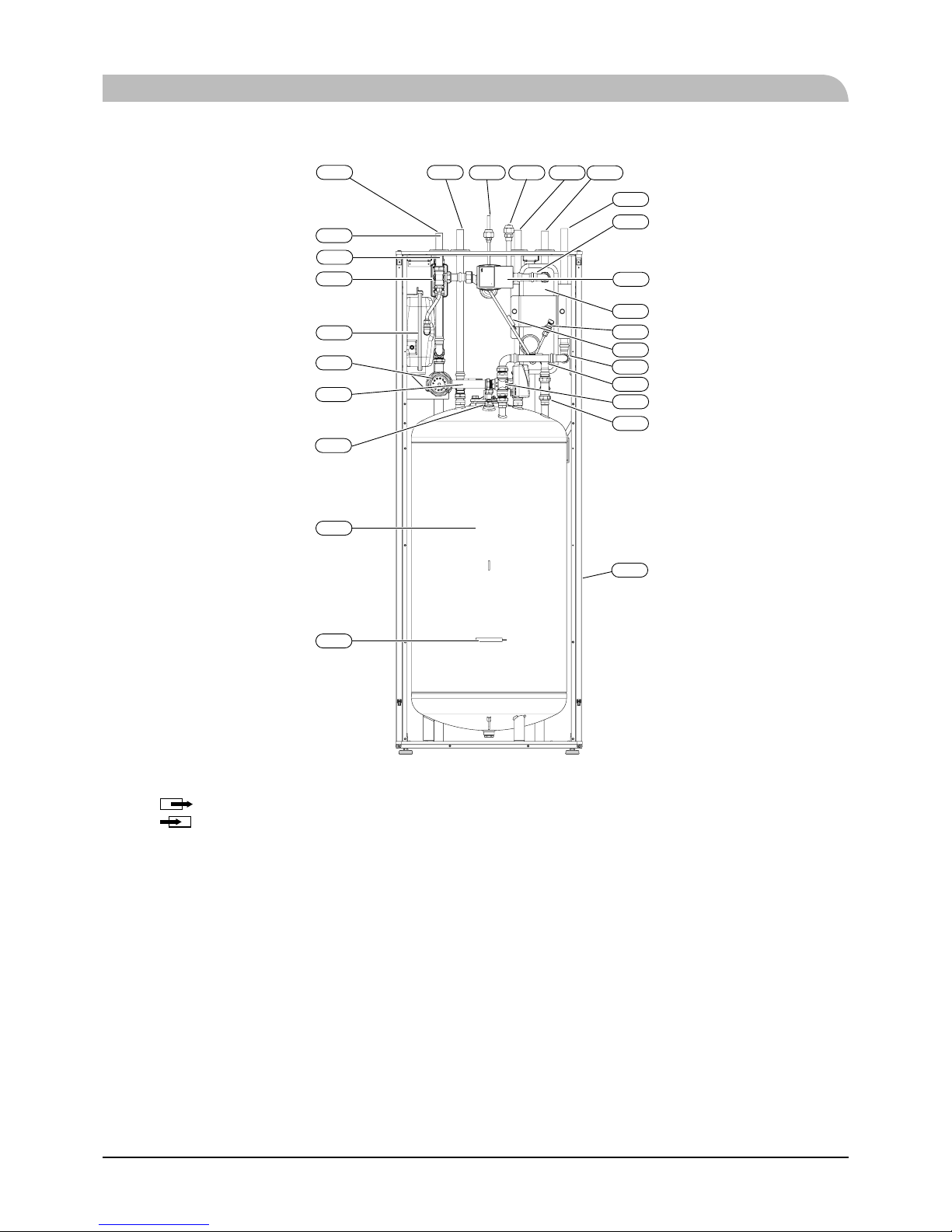
HMK60
XL10
XL11
QN12
QN10
GP12
EP2
CM1
EB1
XL4 XL13
XL14
XL3
XL2
XL1
BP4
EB15
BT15
BT71
BT6
EB2
BT64
BT63
BT7
BT12
BT3
BT25
Pipe connections
XL1
(
)
Connection, heating medium, supply
XL2
(
)
Connection, heating medium, return
XL3 Connection, cold water
XL4 Connection, hot water
XL10 Connection, cooling
XL11 Connection, safety group, manometer
XL13 Connection, liquid cooling medium
XL14 Connection, gas cooling medium
HVAC elements
CM1 Diaphragm expansion vessel, closed
QN10 Isolation valve, domestic hot water/central heating
QN12 Isolation valve, cooling/heating
GP12 Circulation pump
EP2 Heat exchanger
Sensors
BP4 Pressure sensor, high pressure
BT3 Temperature sensor, heating medium return
BT6 Temperature sensor, hot water loading
BT7 Temperature sensor, top of the hot water heater
BT12 Temperature sensor, condenser outlet
BT15 Temperature sensor, liquid
BT25 Temperature sensor, heating medium supply
BT63 Temperature sensor, heating medium supply
downstream the submersible heater
BT64 Temperature sensor, cooling medium supply
BT71 Temperature sensor, heating medium re- turn
Others
EB15 HMK 60
PF3 Serial number
EB2 Domestic hot water tank
General information for the installer
9
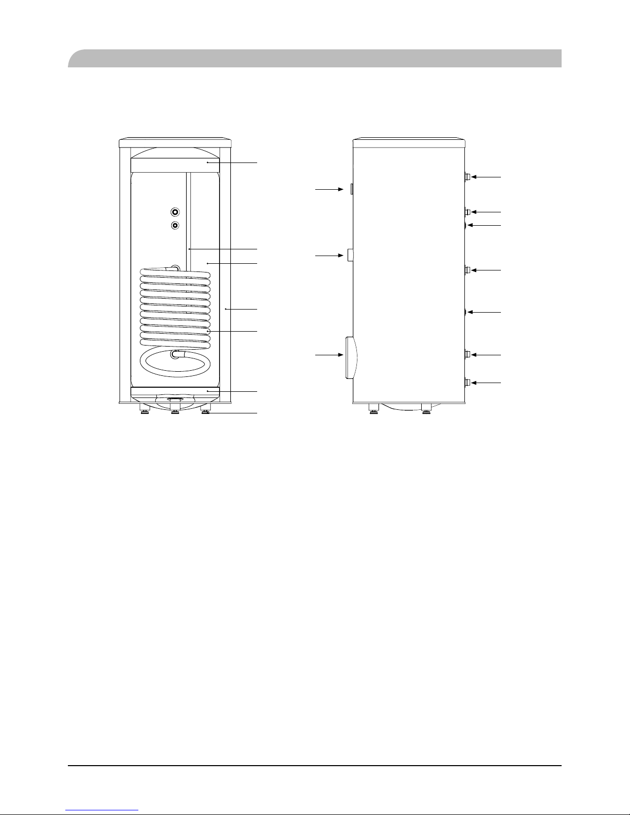
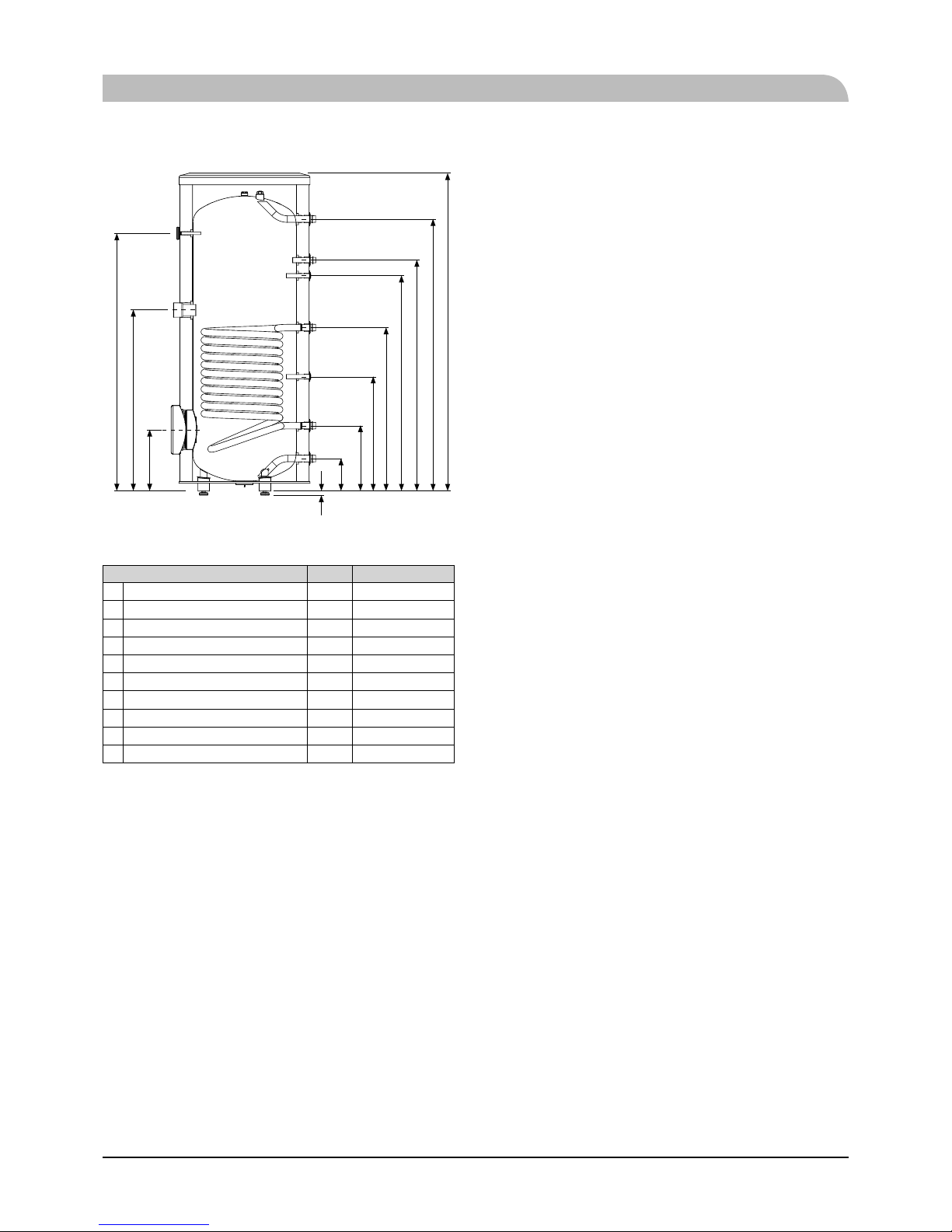
PT300
1
2
3
4
5
6
7
8
9
10
11
12
13
14
13
15
16
Section of the PT300 storage tanks.
1. Upper insulation of the storage tank
2. Protective magnesium anode
3. Enamelled tank
4. Side insulation of the storage tank
5. Coil
6. Lower insulation of the storage tank
7. Adjustable foot
Side view of the PT300 storage tanks.
8. Thermometer
9. Connector pipe for mounting electric heating unit
10. Inspection opening
11. Hot water intake connector pipe
12. Hot water circulation connector pipe
13. Temperature sensor cover
14. Coil supply connector pipe
15. Connection of return line from the coil
16. Cold water supply connector pipe
General information for the installer
10
Transport and storage
Indoor unit and tank unit must be transported and stored
vertically in dry conditions.
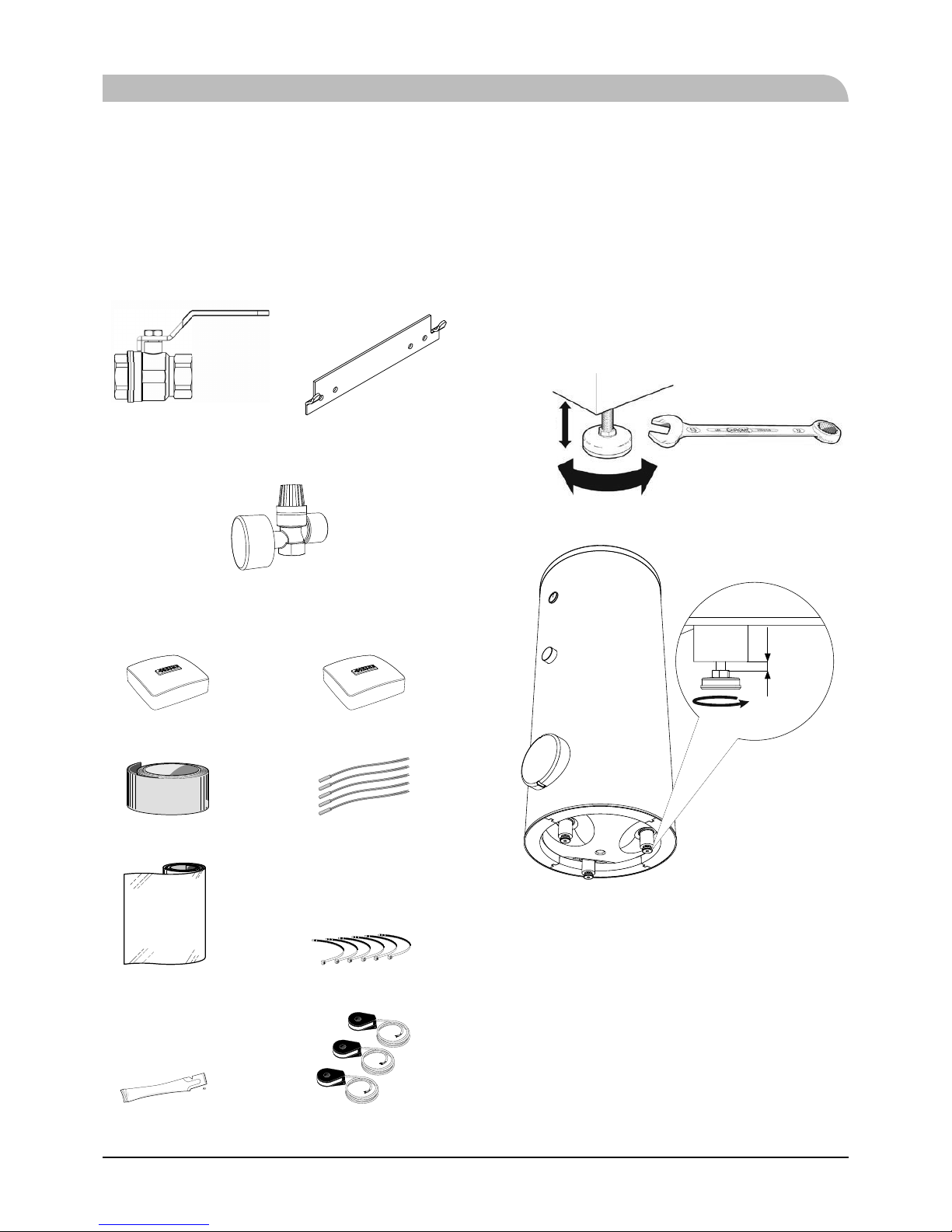
Supplied components
HSB60 Indoor unit
Particle filter R25 (HQ1). Brackets kit
HMK60 Indoor unit with tank
Safety valve with pressure gauge
RC-HY20/40 Control unit
Room sensor (RC-HY40 only)Outside sensor
LEK
Temperature sensorInsulation tape
LEK
Cable tiesAluminium tape
LEK
LEK
LEK
Current sensor (RC-HY40 only)Heating pipe paste
Assembly
■ It is recommended that indoor unit is installed in a room
with existing fl oor drainage, most suitably in a utility room
or boiler room.
■ For indoor unit and control unit, the mounting surface must
be fi rm, fl at and vertical, preferably a concrete wall.
■ Indoor unit with tank and tank unit must be set on a solid
waterproof base that would keep the weight of the unit. The
height-adjusting legs allow for levelling and stable setting.
HMK60
20-40 mm
Wrench size 13
PT300
0-15 mm
■ For indoor unit with tank, floor drain port is required to
connect drain hose in case cooling function is used.
■ Install indoor unit with its back to an outside wall, ideally
in a room where noise does not matter. If this is not
possible, avoid placing it against a wall behind a bedroom
or other room where noise may be a problem.
■ Route pipes so they are not fixed to an internal wall that
backs on to a bedroom or living room.
■ Install indoor unit with tank, tank unit and its pipings to
indoor unit indoors in order to avoid icing.
■ Ensure free space described in the following figures for
future maintenance.
General information for the installer
11
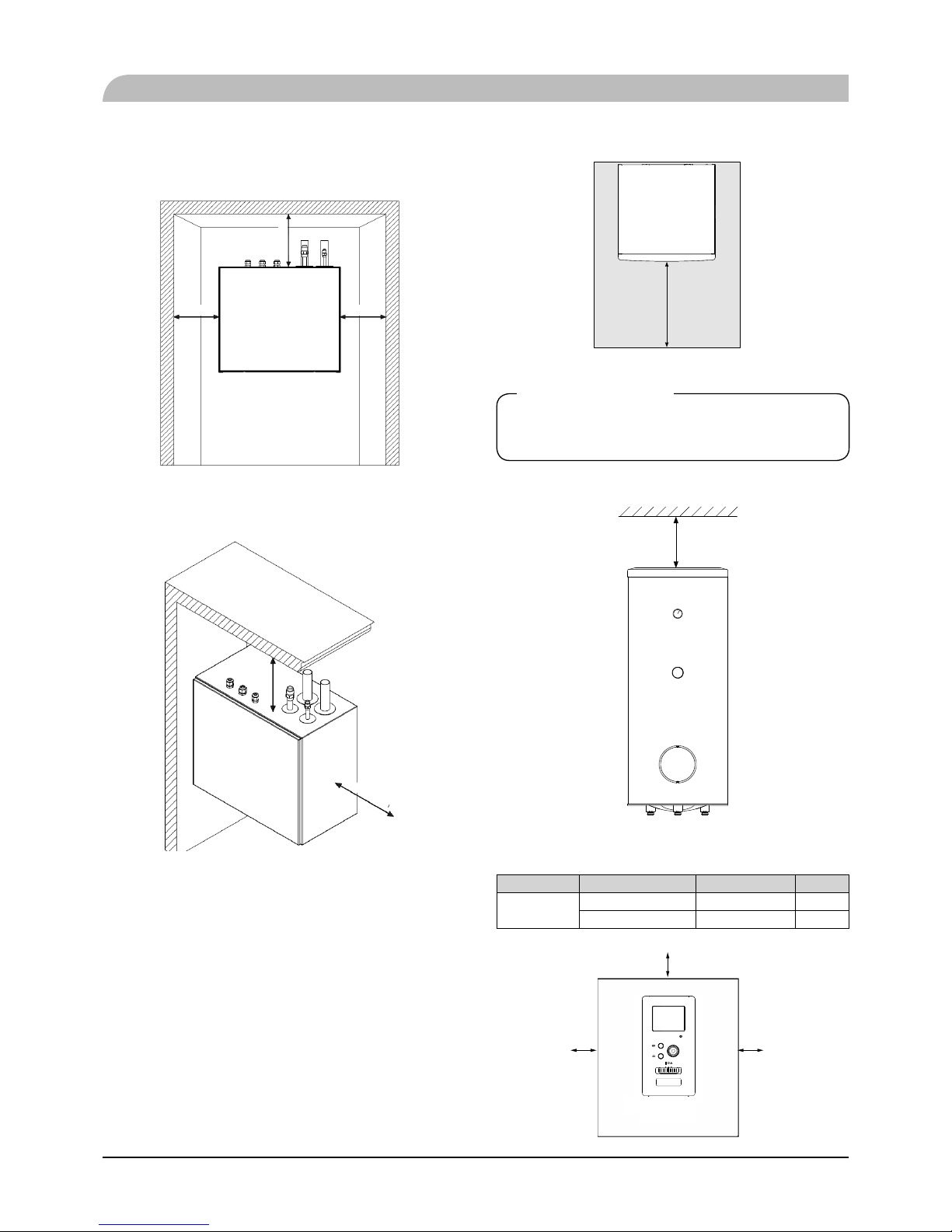
HSB60
Recommendation for positioning on wall
Min. 200mm Min. 200mm
Min. 300mm
Recommendation for positioning in corner
Min. 400mm
Min. 400mm
*Min 800mm is required in front
General information for the installer
HMK60
800 mm
IMPORTANT
For HMK60, leave 10 – 25 mm free space between the indoor
module and the back wall f or cables and piping.
PT300
A
min
A
min
is required on top to replace anode bar, and 500 mm is
required in front to replace immersion heater if equipped.
Application Connector pipe dia. Type of anode A
min
PT300
1" Chain ø26×8 150 mm
¾" Titanium anode 200 mm
RC-HY20/40
100 mm
100 mm 100 mm
12
General information for the installer
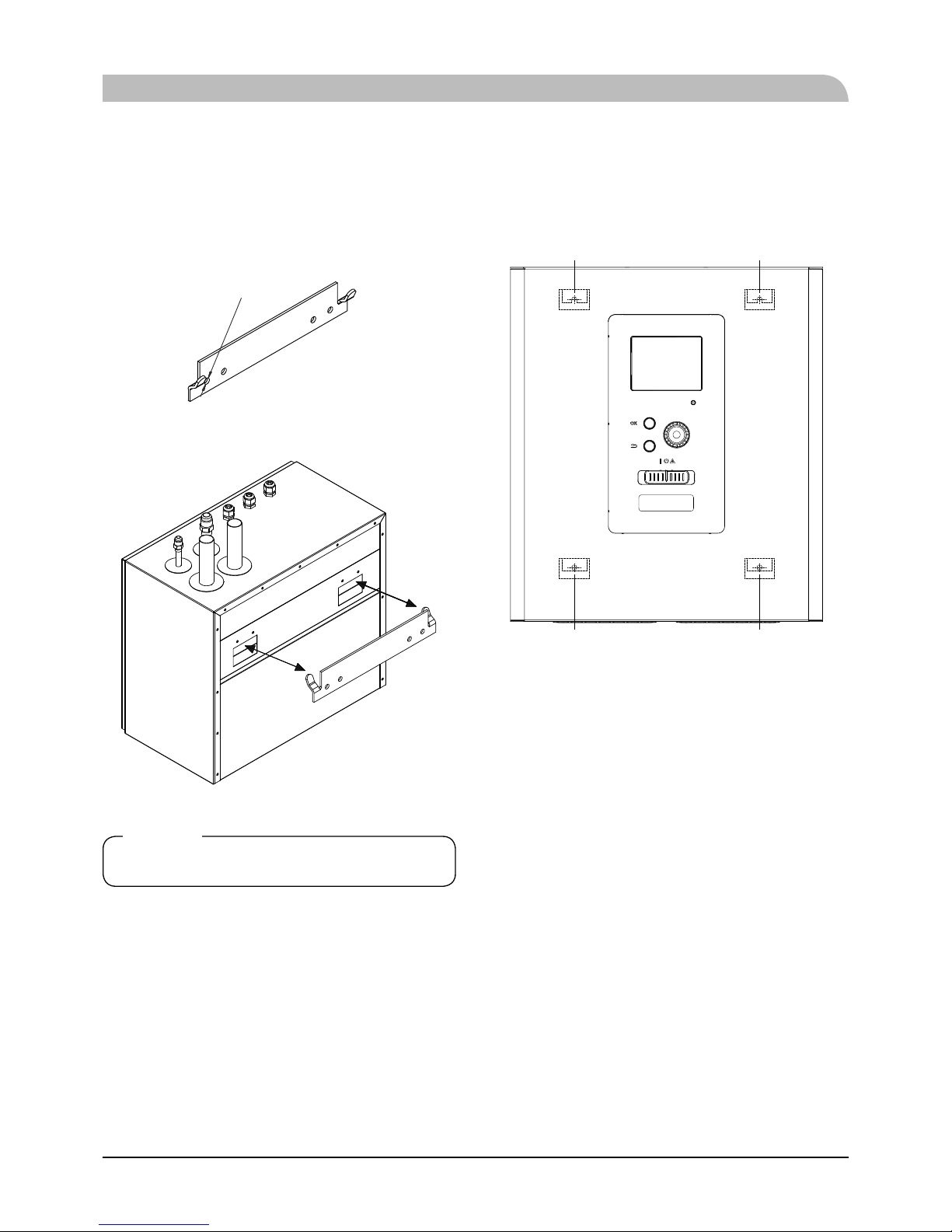
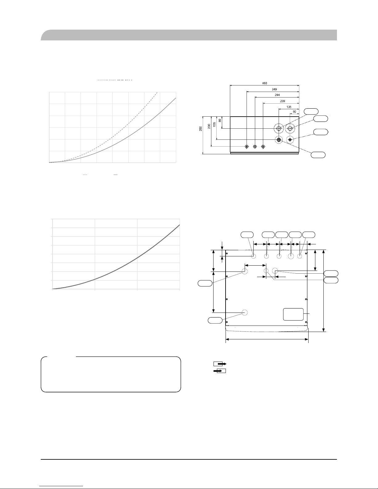
Hanging indoor unit
It is recommended that the split box is installed in a room with
existing fl oor drainage, most suitably in a utility room or boiler
room.
1. The bracket for the split box is mounted to the wall by use
of appropriate screws.
4-ø10
2. Insert HSB60 in the bracket mounted to the wall.
NOTE
Indoor unit weigh 16 kg excluding water inside.
Hanging control unit
Use all mounting points and install control unit upright against
a fl at wall. Make sure whole back surface faces the wall.
Mounting point Mounting point
Mounting point Mounting point
13
Dimensioning expansion vessel
The expansion vessel volume must be at least 5% of total water
volume in the circulation system.
HMK60 is equipped with an expansion vessel with a volume
of 10 liters.
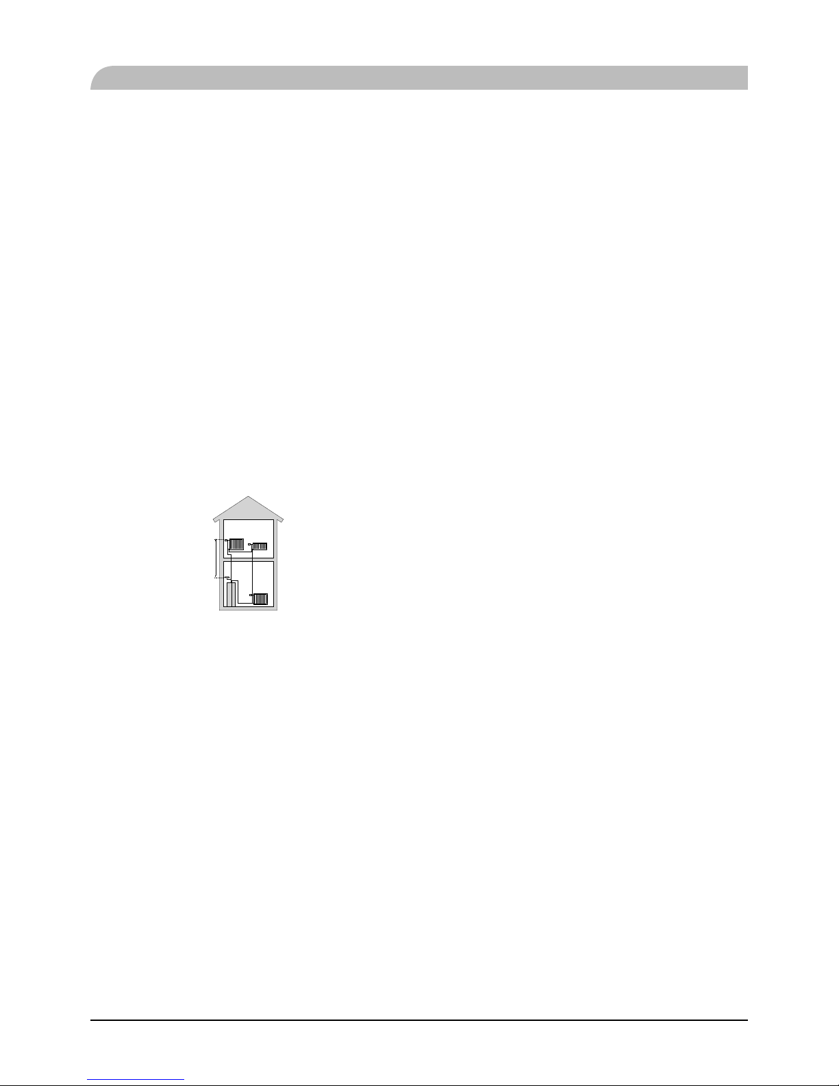
Initial pressure and max height difference
Recommended maximum height diff erence between expansion
vessel and the highest point in the system is 5m.
The initial pressure of the pressure expansion vessel must be
dimensioned according to the maximum height (H) between
the vessel and the highest positioned radiator, see figure. An
initial pressure of 0.5 bar (5 mvp) means a maximum permitted
height diff erence of 5 m.
If the standard initial pressure in the pressure vessel is not high
enough it can be increased by filling via the valve in the
expansion vessel. The expansion vessel’s standard initial
pressure must be entered in the check list on User’s manua1.
Any change in the initial pressure affects the ability of the
expansion vessel to handle the expansion of the water.
Consult local distributor in case height diff erence exceeds 5m.
H
Recommended installation order
1. Hang indoor unit and control unit to appropriate position
and connect indoor unit and tank unit.
2. Connect indoor unit to climate system, cold and hot water
lines as well as any external heat sources. See page 14, 15.
Also see docking descriptions on page 26-28 and further
on.
3. Install refrigerant pipes according to the description on the
Installation manual for outdoor unit.
4. Connect current limiter, any centralised load control and
external contacts as well as the cable between indoor unit
and outdoor unit.
5. Connect incoming electricity to indoor unit and/or outdoor
unit. See page 34-36.
6. Follow the commissioning instructions on page 37-55.
General information for the installer
14
Pipe installation
General
Pipe installation must be carried out in accordance with current
norms and directives.
A following table shows plumbing necessary for each product.
Refrigerant Plumbing
HSB Necessary Necessary
HMK Necessary Necessary
PT ⸺ Necessary
PC-HY ⸺ ⸺
This heat pump system is designed for low or medium
temperature heating system. It is recommended water
temperature must not exceed 55°C on supply and 45°C on
return at lowest design outdoor temperature (DOT) though
indoor unit can operate with a return temperature of up to 65°C
and an outgoing temperature from the unit of 65°C.
Indoor unit is not equipped with shut off valves; these must be
installed outside the heat pump to facilitate any future
servicing.
Indoor unit can be connected to the radiator system, floor
heating system and/or fan convectors.
Safety valve is not equipped with in indoor unit. Make sure to
install safety valve in the circuit.
FDCW60
AA25
P
HSB60
BP4
BT3BT15
BT12
XL14
XL13
XL1
XL2
PT300
Pipe installation
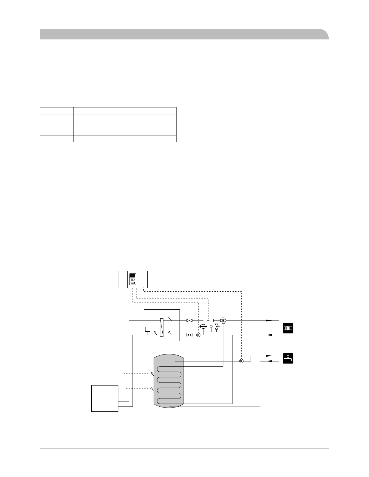
Installation diagram
FDCW60VNX-A outdoor unit provides heat for space heating and domestic hot water using free energy in the outdoor air within the
range of low temperature up to -20°C. Connection is diff erent according to the type of indoor unit (see below fi gures). The system is
controlled by RC-HY20 or RC-HY40 control unit.
HSB60
HSB60 indoor unit is equipped with plate heat exchanger. It needs to install expansion vessel, shut-off valves, safety valve, electric
heater and circulation pump to make a complete heating system. In case domestic hot water is required, 3 way valve and tank is also
necessary.
15
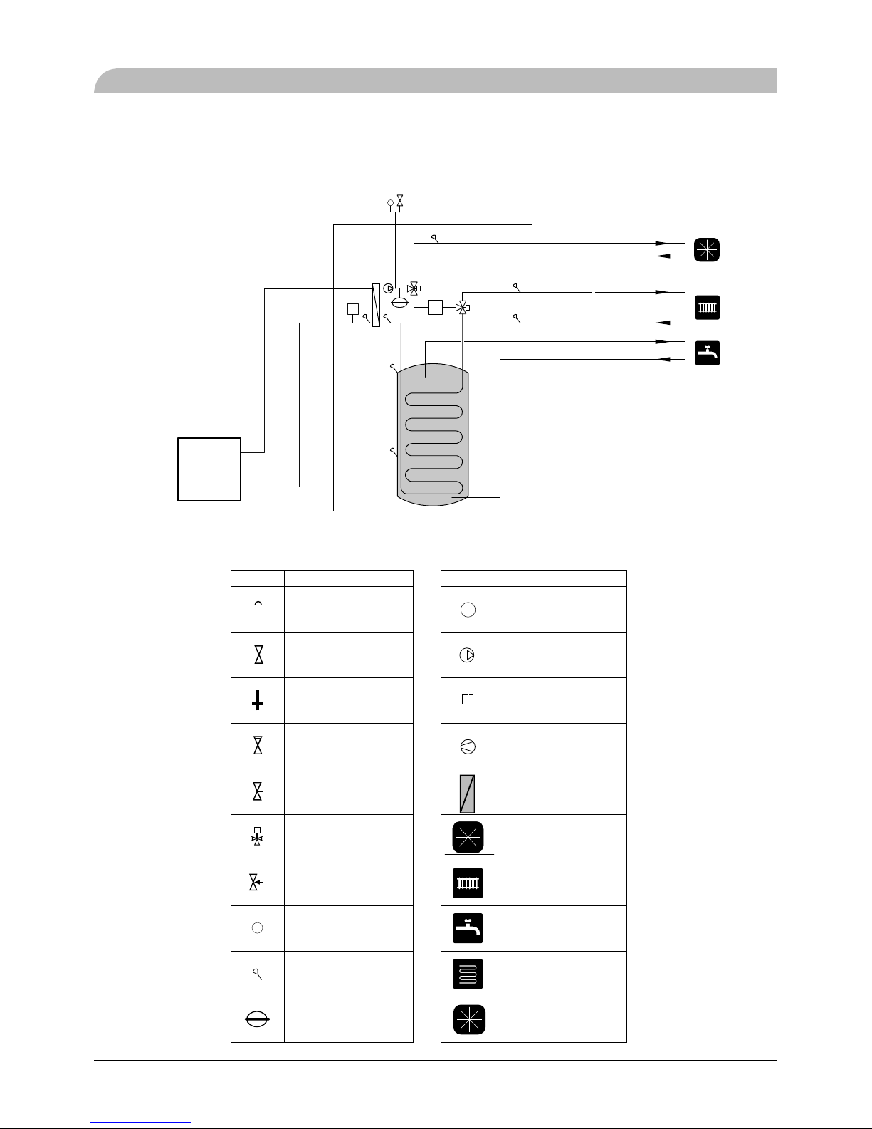
HMK60
HMK60 indoor unit is equipped with coil water heater, expansion vessel, safety valve, electric heater, plate heat exchanger,
sensors and gauge, and circulation pump.
P
FDCW60
XL10
BP4
EH
XL1
XL11
XL14
XL13
XL2
XL4
XL3
HMK60
Pipe installation
Symbol Meaning Symbol Meaning
Vent
P
Manometer
Cut-off valve Circulation pump
Water tap Particulate fi lter
Non-return valve Compressor
Balancing valve Heat exchanger
Three-way valve Cooling
Safety valve Central heating system
T
Thermometer Domestic hot water
Temperature sensor
Heating systems Floor
heating
Diaphragm expansion
vessel
Cooling system

16
System requirements
The minimum water volume in the climate system is subject to
the values in the table below. If it is not fulfi lled, volume
vessel must be installed.
For more options, see the docking description on Page 24.
(liter)
With underfl oor
cooling application
Without underfl oor
cooling application
HSB60, HMK60,
FDCW60VNX-A
50 20
Overflow valve
NOTE
A free f low is required for all docking options, which
means that an over fl ow val ve must be installed.
The circulation pump may become damaged.
Pump capacity diagram
HSB60
HSB60 is not equipped with circulation pump.
This graph shows the characteristic of CPD11-25/55.
0
10
20
30
40
50
60
70
80
Pressure
[kPa]
0 0.1 0.2 0.3 0.4 0.5 0.6 0.7 0.8
Flow [l / s]
HMK60
Pressure
[kPa]
Flow [l / s]
Pipe installation
17
Pressure drop in indoor unit
HSB60
0
5
10
15
20
25
30
0,0
0,1 0,2 0,3 0,4 0,5 0,6 0,7 0,
8
Tryckfall HBS05
HSB60, 140HSB100
kPa]
Flow [l / s]
HMK60
0
2
4
6
8
10
12
14
16
0 0.2 0.4 0.6
[kPa]
Flow[l/s]
Connection of extra circulation pump
When connecting extra circulation pumps, requirements for
pressure, maximum flow etc must be met. See page 27 for
location.
NOTE
Non-ret urn v alve must be install ed in c ase e xt ra cir culat ion
pump is used. See page 27 for the position.
The circlulation pump may become damaged.
Dimensions and pipe connections
HSB60
XL13
XL1
XL14
XL2
Pipe connections
XL1 (Red mark) Climate system, fl ow ø28 mm
XL2 (Blue mark) Climate system, return ø28 mm
XL14 Gas line refrigerant, fl are ½
XL13 Liquid line refrigerant, fl are ¼
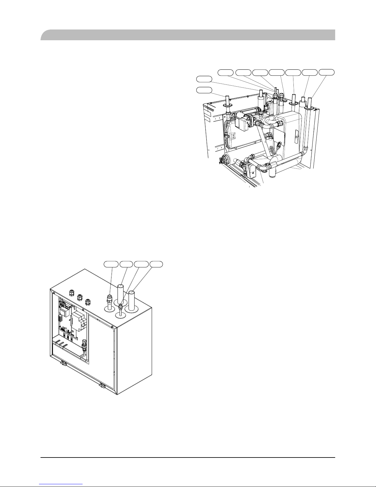
HMK60
600.5
610.5
300
156
93.5 92.5
XL11
XL14
XL1XL2XL3XL5XL4
XL13
PF3
XL10
87
63
55
65
155
44
152
Pipe connections
XL1 Connection, Heating medium supply ø22 mm
XL2 Connection, Heating medium return ø22 mm
XL3 Connection, cold water ø22 mm
XL4 Connection, hot water ø22 mm
XL5 Connection, circulation ø15 mm
XL13 Connection, liquid cooling medium ¼ ࡉ
XL14 Connection, gas cooling medium ½ ࡉ
XL10 Connection, cooling ø22 mm
XL11 Connection, safety valve ø22 mm, manometer
Other information
PF3 Serial number plate
(
)
(
)
Pipe installation
18
PT300
1634
1398
1187
1107
840
588
336
167
21-0/+15
315
930
1325
F
E
D
N
L
K
J
I
H
G
Connection U/m PT300
D
Inspection opening mm ø120
E
Heating unit connection inch 1½ Female
F
Thermometer enclosure mm ø10 Female
N
Hot water outlet inch 1 Male
L
Hot water circulation inch ¾ Male
K
Temp. sensor enclosure (BT7) mm ø16 Female
J
Coil supply inch 1 Male
I
Temp. sensor enclosure (BT6) mm ø16 Female
H
Return from coil inch 1 Male
G
Cold water input inch 1 Male
Pipe installation
19
Pipe installation
Water circuit
Connection to heating system
Connect XL1 to supply line and X2 to return line from
heating system.
■ All required safety devices and shut-off valves must be
installed as close to the indoor unit as possible.
■ Install bleed valves where necessary, highest point of the
water system in usual case.
■ When connecting to a system with thermostats on all
radiators, install an overfl ow valve or remove some of the
thermostats to ensure suffi cient fl ow.
■ See section Dockings on page 25 for outline diagram.
■ Install a safety valve with manometer on heating circuit and
hot water circuit. (FL2)
For HSB60 install a safety valve for heating circuit on the
water pipe returning to indoor unit since it doesn’t have
port for FL2.
The entire length of the overfl ow water pipe from the safety
valves must be inclined to prevent water pockets and must
also be frost proof.
■ The end of overfl ow water pipe from the safety valves must be
left open to the atmosphere. The water may drip from the pipe.
HSB60
XL14 XL1 XL13 XL2
Install safety valve as close to XL2 as possible.
HMK60
XL9XL8
XL3
XL5 XL4 XL2
XL1
XL10
XL11
Install safety valve FL2 on XL11.
Connection to hot water heater
For HSB60 indoor unit, it is necessary to connect PT300 tank
unit applying 3 way valve in order to use domestic hot water
function.
For HMK60 indoor unit, 180L tank unit is integrated in
indoor unit.
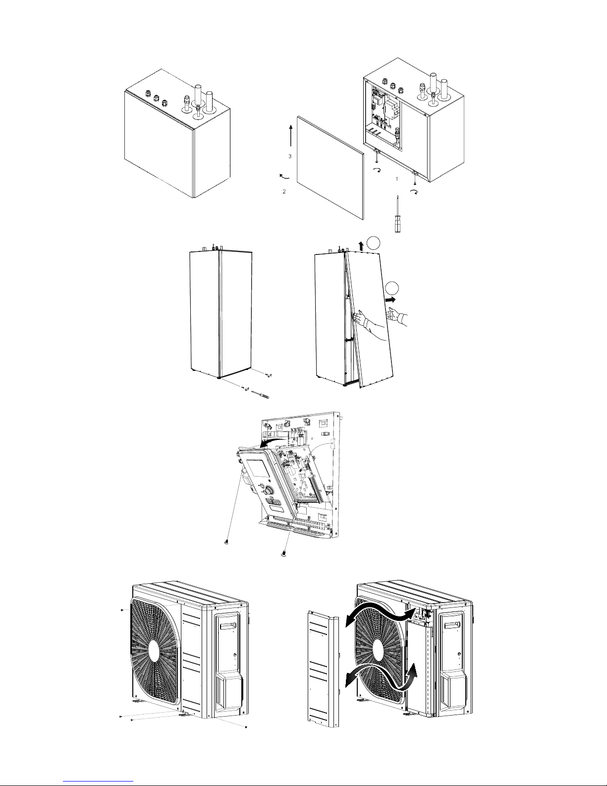
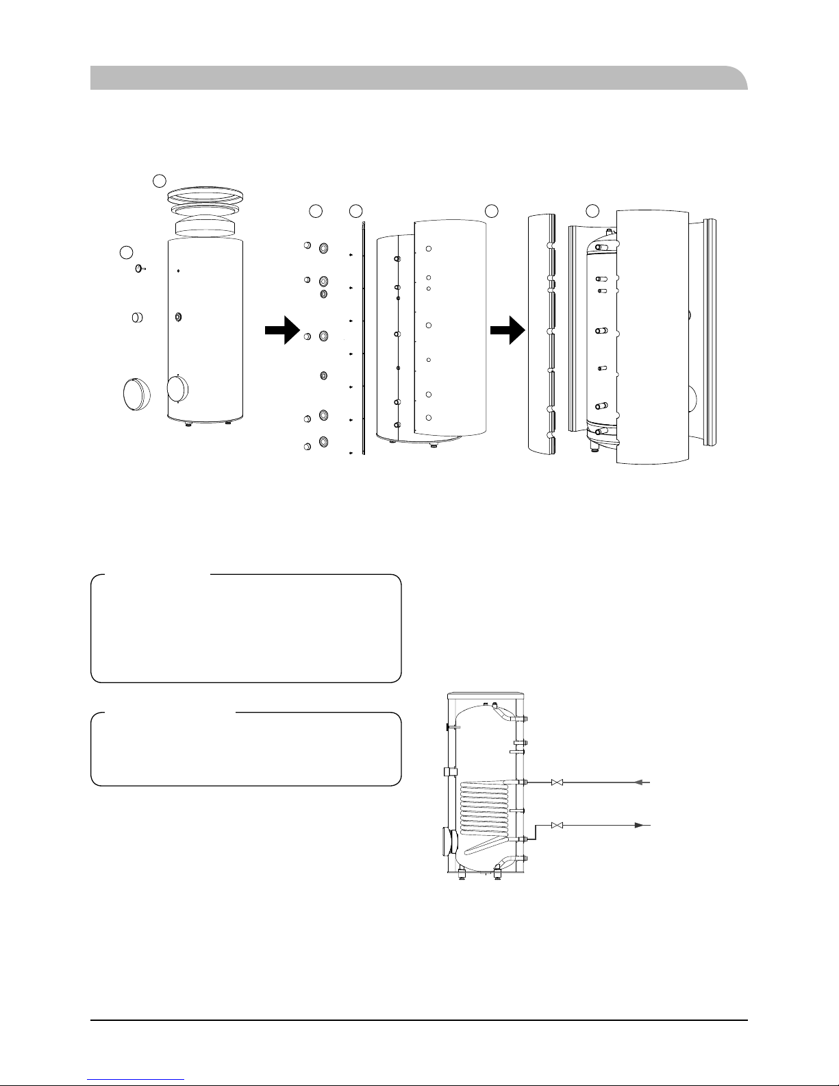
Housing disassembly of tank unit
Removable housing with thermal insulation facilitates transport and installation of the storage tank. Disassembly the housing in the following order (see below fi gure):
1. Remove the Temperature gauge, plug of the heating element connector pipe and blanking plate of the inspection
opening.
2 Remove the upper cover of the housing together with
thermal insulation.
3. Remove the plugs from the connector pipes and black
bushings.
4. Remove the fixing screws and the strip connecting the
housing jacket.
5. Remove the jacket surrounding the tank (housing jacket.)
6. Remove the four-piece thermal insulation.
After the installation of the storage tank in its fi nal location,
reinstall the removed components in the reverse order.
20
Housing and thermal insulation disassembly
1
2
34
5
6
Connecting hot water tank to indoor unit
CAUTION
Instal lation and commis sioning of the storage tank
shall onl y be d one b y ap propri atel y qualif ied install er.
The installer should inform the user of the functions of
the product and provide the necessary in formation on its
safe use.
Information
We recommend installing a strainer in order to protect the
pumps, check valve and the components of the heating
system.
■ Tank and its pipings to indoor unit must be installed
indoors where the temperature wouldn't drop below 15°C
in order to prevent pipings from icing.
■ Maximum piping length between indoor unit and tank is
10 m.
■ Tank unit should be placed on firm, preferably a concrete
fl oor or foundation.
Pipe installation
■ Tank unit can be aligned using the adjustable feet.
■ Protection against overpressure shall be made in accordance
with the relevant regulations.
■ Connect the heating system according to the installation
diagram (see fi gure).
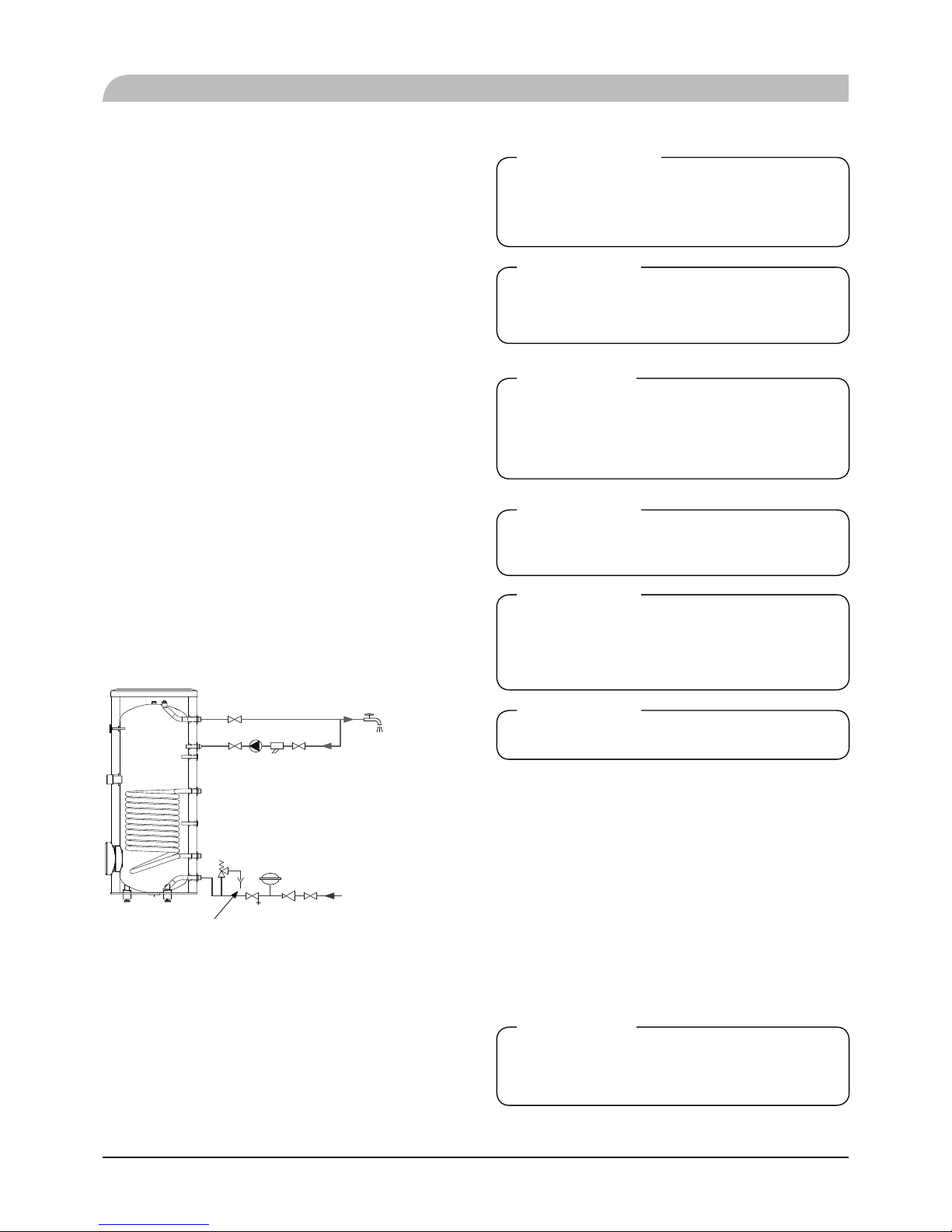
Installation diagram of the PT storage tank with one coil.
1
2
2
supply from heat
pump
1. PT storage tank
2. Cut-off valve
return to heat pump
21
Connecting hot water tank to water main
■ Install a mixing valve if the temperature exceeds 60 °C.
■ It is recommended to install a thermostatic mixing valve
for stable temperature hot water supply.
■ Connect the storage tank to the water supply system of
water pressure at least 1 bar and max 10 bar. Install a
pressure reducer if the pressure at the cold water inlet to the
tank is higher than allowed.
■ Install a safety valve which have a maximum 10.0 bar
opening pressure on the incoming domestic water line
according to outline diagram in order to protect the storage
tank against overpressure. Pressure increases during heating
the water.
■ During heating the water, small and temporary water fl ow
from the safety valve can occur, which indicates that the
pressure has increased above the rated value, which
triggered the valve. This may in no way be prevented.
■ Safety valve drain line should be installed with a decline, in
an environment free of freezing and remain open to the
atmosphere. The manufacturer is not responsible for
fl ooding the room through the safety valve.
■ Blocked safety valve can cause equipment failure. Drain
the outfl ow from the safety valve to the sewerage or drain
grate.
■ See section Dockings on page 25 for outline diagram.
■ Connect the water supply system according to the
installation diagram.
Installation diagram of the PT storage tank with one coil.
1
2
22
2
6
7
38
45
DHW
hot water circulation
(optional)
to sewerage
water supply system
1. PT storage tank
2. Cut-off valve
3. Safety valve
4. Drain valve
5. Pressure reducer (option, if the pressure in the system
exceeds the allowable value)
6. Strainer
7. Hot water circulating pump
8. Hot water expansion vessel
Information
In order to minimi ze t he f low of wate r f ro m the saf ety val ve
associated with the thermal expansion of the liquid, it is
advisable to install a suitable expansion vessel at the cold
water connection (see item 8.)
CAUTION
Installation of the appropriate safety valve in the cold
water supply line protecting the unit against
overpressure is mandatory!
CAUTION
Installation of necking of any kind (such as reducers, dirt pockets,
etc.) and cut-o valves between the storage tank and the safety
valve is not allowed. Only a T-pipe with a drain valve and a T-pipe
with an expansion vessel may be installed in these line sections.
CAUTION
Never block the safety valve or drain line. This can cause
a dangerous overpressure in the storage tank.
CAUTION
When heating water, slight, temporary discharge from
the safety valve can occur. This is a correct safety valve
function. Any attempt to interfere in its operati on can
lead to the danger and destruction of the storage tank.
CAUTION
Never use the equipment with clogged safety valves.
Connection
After the installation and levelling the tank, follow the procedure below (for the connector pipe symbols, refer to page 19):
1. Remove protecting plugs from the connector pipes
2. Connect the hot water intake line (N).
3. Connect the cold water supply line together with the
required safety valves (G).
4. If the system has the hot water circulation system, connect
it to the connector pipe (L). Otherwise, plug the pipe.
5. Connect the supply (J) and return (H) of the heating
medium to the coil.
CAUTION
If there is an electric heating module installed in the
storage tank, ll the tank with water before connecting
it to the electrical installation.
Pipe installation
22
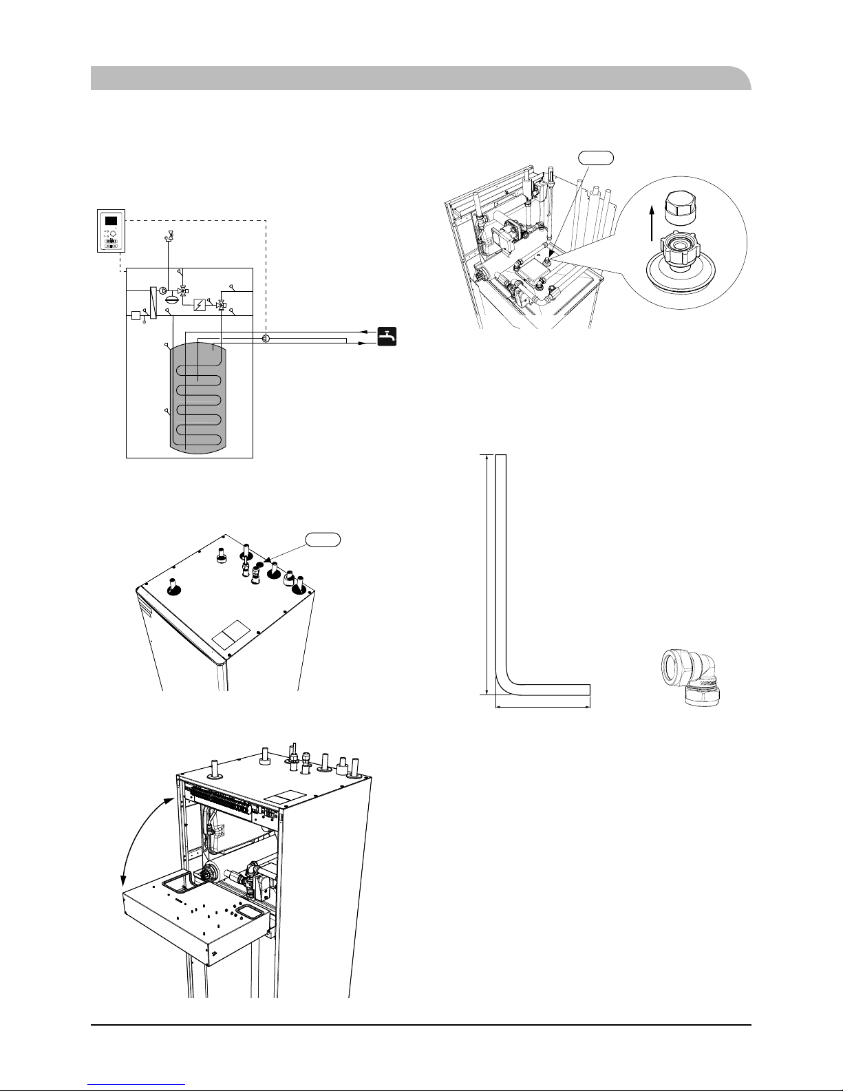
Hot water circulation circuit
Hot water circulation function is available for HMK60 and
PT300.
HMK60
To connect the circulation:
1. Remove the XL5 plug from the top of the housing.
XL5
2. Remove the front panel, then slide the control panel down
to access the hydraulic connections.
3. Remove the plug from the circulation pipe (XL5).
XL5
4. Install the elbow, facing the rear housing, on the circulation
pipe.
5. Connect the pipe to the elbow, with the dimensions shown
in the fi gure below, leading pipe in the top of the housing,
in place of the XL5 plug. Mount the pipe insulation.
520
120
Circulation pipe dimensions (*) Elbow 15x15 (*)
6. At the outlet of the circulation tube, install the circulation
pump and then connect its control to the RC-HY (Chapter 5
Electrical connection).
7. Install the control panel and the front panel.
(*) Prepared on site.
PT300
If the system has the hot water circulation system, connect it to
the port L (see page 19).
Then install the Cut-off valves, circulation pump and strainer.
Pipe installation
23
Connection of external heat source
External heat source, e.g. a gas or oil boiler or electric heater,
can be connected on supply line of heating system (XL1).
Pipe installation
Refrigerant circuit
Connecting refrigerant pipes
See Installation manual for outdoor unit.
Piping insulation
Install insulation on all piping in order to avoid condensation
during cooling operation.
It is also strongly recommended to insulate piping for heating
only application in order to avoid getting burned or reducing
the heating capacity.
The thickness of the insulation should be 20mm where the
relative humidity exceeds 70%.
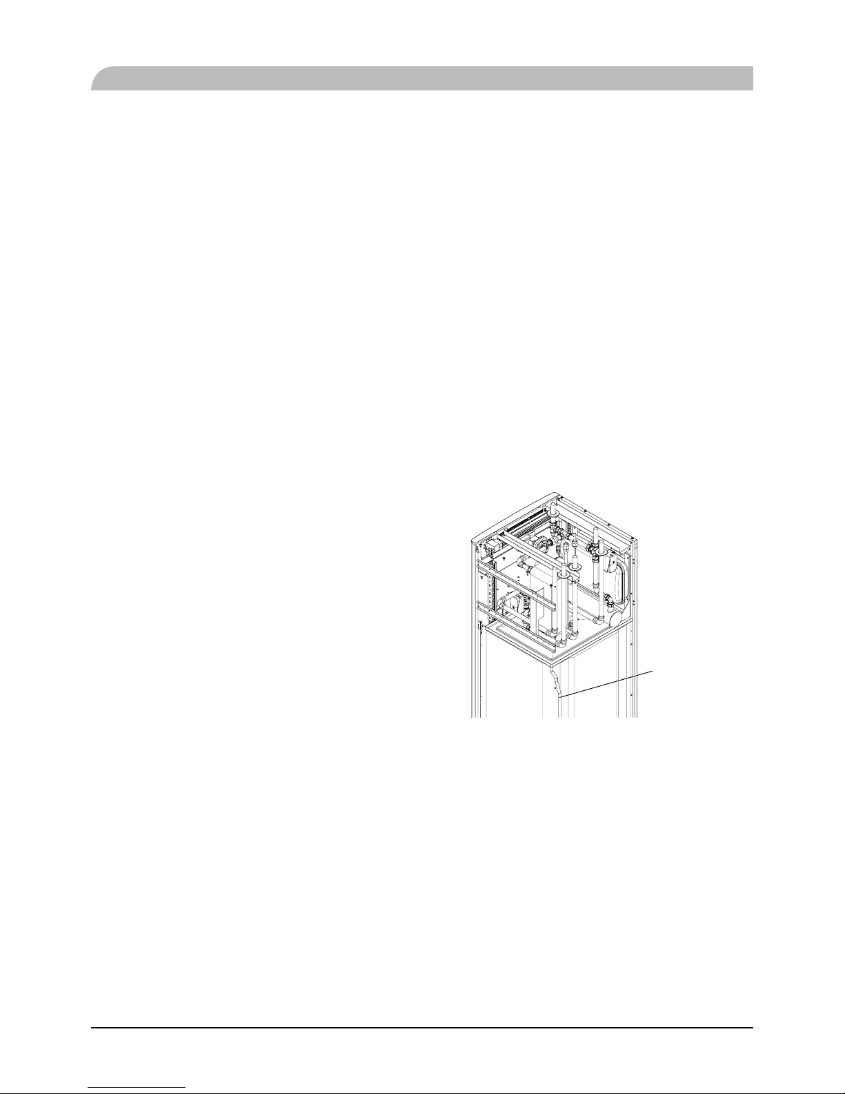
Drain connection
HMK 60 is equipped with a condensate hose in the heat
exchanger section. The hose drains all condensate away from
the device to minimize the risk of damage. If necessary, the
hose can be extended.
Condensate hose
24
Dockings
General
Installation requirements
Hydrolution can be connected in several diff erent ways, some of which are shown on the following pages.
Min flow, climate system
Max flow, climate system
Min flow, climate system, at 100% circulation pump speed
Min volume, climate system during underfloor cooling
Min volume, climate system during heating, cooling
Max supply temp. cooling
Min supply temp. cooling
Max supply temperature with compressor at outdoor temp -15°C
Max temperature from external heat source
Max temperature in indoor unit
Max temperature, climate system
Max pressure, climate system
0.25 MPa (2.5 Bar)
FDCW60VNX-A
HMK60HSB60
65 °C
Highest recommended supply/return temperature
55/45°C
65 °C
65 °C
58 °C
25 °C
7 °C
20 L
50 L
0.29 L/s
0.19 L/s
0.09 L/s
Nominal system flow heating (ѬT=5K)
0.29 L/s (6kW, 7/45°C)
Nominal system flow cooling (ѬT=5K)
0.28 L/s (5.8kW, 35/7°C)
External circulation pump must be used when the pressure drop in the system is greater than the available external pressure. In such
cases, a bypass line with non-return valve must be installed.
Use an overfl ow valve if system fl ow cannot be guaranteed.
Symbol key
MeaningSymbol
Venting valve
Shut-off valve
Non-return valve
Control valve
Safety valve
Temperature sensor
Expansion vessel
Pressure gauge
P
Circulation pump
Shunt / shuttle valve
Fan
Pipe installation

25
Pipe installation
Docking alternatives
Heating system can be constructed in several different ways
combining indoor unit, tank, control unit and other accessories.
For further option information, see page 84.
In the system example shown on the following page, heating,
hot water as well as cooling operation are available.
Additional heating is helpful on the cold day of the year as the
energy from the air is reduced. It is also recommended as backup in case the heat pump operation is blocked for any reason
(e.g. ambient temperature exceeds the operation limit of heat
pump).
NOTE
The heating medium side and the hot water side must be
f itted w ith the necessar y safet y equipment in accordance
with the applicable regulations.
This is the outline diagram. Actual installations
must be planned according to applicable
standards.
Explanation
AA25 Controller
BT1 Outdoor sensor
1)
BT6 Temperature sensor, hotwater charging
1)
BT7 Temperature sensor, hot water top
1)
BT25 Temperature sensor, external supply line
1)
BT50 Room sensor
BT63 Temperature sensor, external supply line after
electric heater
BT71 Temperature sensor, external return line
1)
GP10 Circulation pump, Heating medium
QN10 Reversing valve, Hot water/Heating medium
2)
EB1 Additional heat
EB1 Immersion heater
KA1 Auxiliary relay/Contactor
2)
EB101 Heat pump system
BP4 Pressure sensor, condensor
3)
BT3 Temperature sensor, return line
3)
BT12 Temperature sensor, condenser supply line
3)
BT15 Temperature sensor, fl uid pipe
3)
EB101 Heat pump
FL10 Safety valve
GP12 Charge pump
2)
HQ1 Particle fi lter
3)
QM1 Drain valve, Heating medium
QM31 Shut-off valve, Heating medium, Flow
QM32 Shut off valve, Heating medium, Return
QM43 Shut-off valve
EQ1 Cooling system
BT64 Temperature sensor, cooling supply line
2)
CP6 Single jacket accumulator tank, cooling
GP13 Circulation pump, cooling
QN12 Reversing valve, Cooling/Heating
2)
Miscellaneous
CM1 Expansion vessel closed, Heating medium
CP5 Buff er vessel
CP10 Accumulator tank with hotwater heating
EB20 Immersion heater
FL2 Safety valve, Heating medium
KA1 Auxiliary relay/Contactor
RN10 Trim valve
1) Included in and supplied with controller
2) Included in and supplied with accessory
3) Included in indoor unit
26
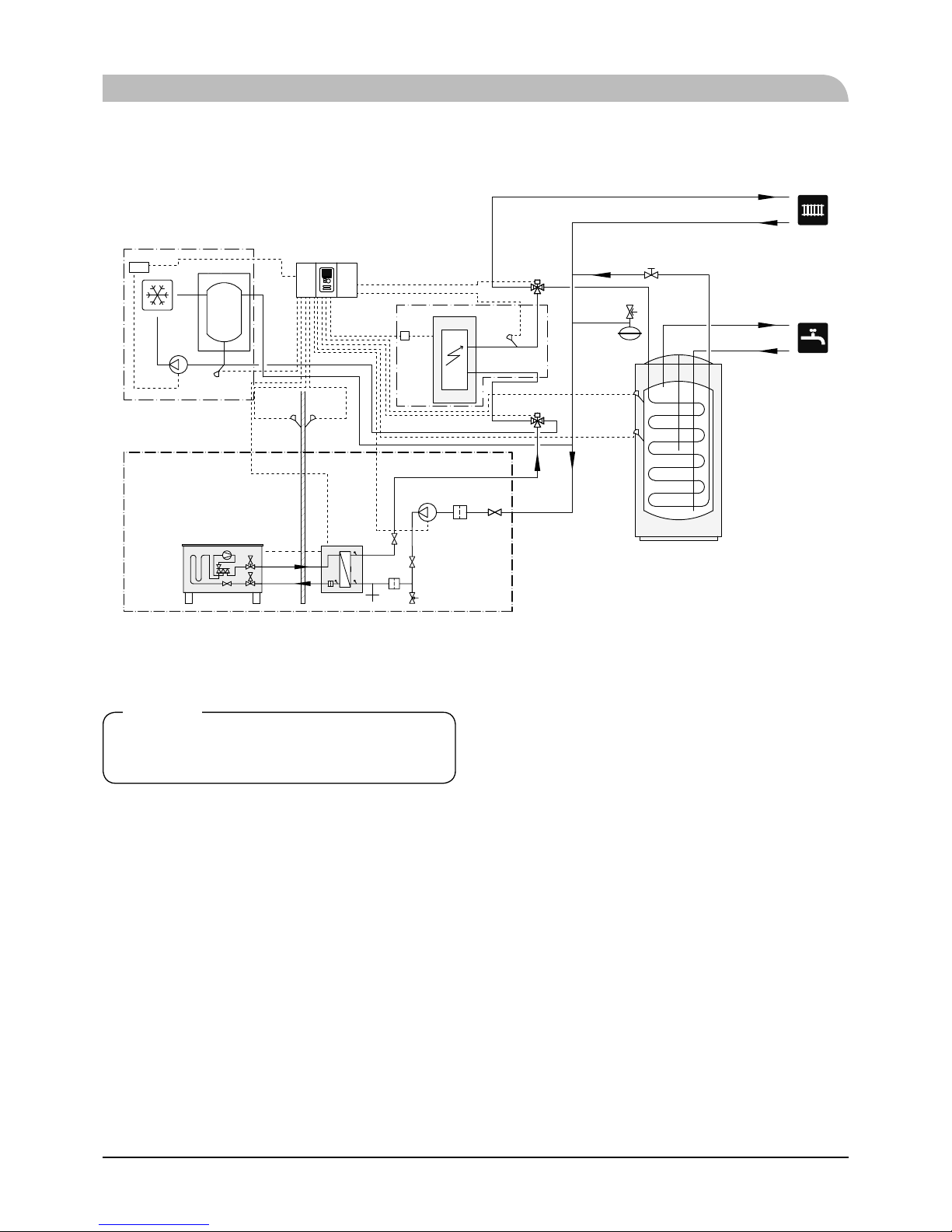
Installation with indoor unit HSB60, tank PT300, controller RC-HY20/40 with step controlled additional heat
before reversing valve for hot water and cooling function (4 pipe system)
-FL2
-CM1
-EB101
-QM43
-GP12
-EB101
-HQ1
-BT1
-AA25
-AA25
-BT50
-AA25
-BT63
-KA1
-EB1
-RN10
-CP10
-AA25-QN10
-AA25-BT7
-AA25-BT6
-GP13
-AA25
-BT64
-EQ1-QN12
-EQ1
-EB1
-CP6-CP6
-QM1
-EZ101
-BT12
-BT3
-BT15
-BP4
-FL10
-QM31
-QM32
-HQ1
-XL14
-XL13
-XL1
-XL2
-EZ102
NOTE
Not all components are shown in this
outl ine di agram.
Controller (AA25) starts and stops the heat pump (EB101) to
meet the heating and hot water demand.
At simultaneous heating and hot water demand, the reversing
valve (AA25-QN10) switches periodically between the climate
system and the water heater/accumulator tank (CP10). When
the hot water heater/accumulator tank is fully charged, the
reversing valve switches to the climate system.
Additional heat (EB1) is turned on automatically when the
heating demand exceeds the heat pump capacity. This is used
for both heating and charging hot water.
The additional heat can also be used for water heater when a
higher temperature is required than the heat pump can produce.
During cooling operation, the reversing valve (EQ1-QN12)
switches to the cooling system (EQ1). If several simultaneous
demands occur while there is a cooling demand, the system
reacts differently. In the event of a hot water demand, the
reversing valve switches back and hot water is produced until
the demand is fulfi lled. In the event of a heating demand, the
reversing valve switches periodically between cooling and
heating. If the cooling demand is met, the reversing valve
switches back to basic mode (heating/hot water).
Pipe installation
27
Pipe installation
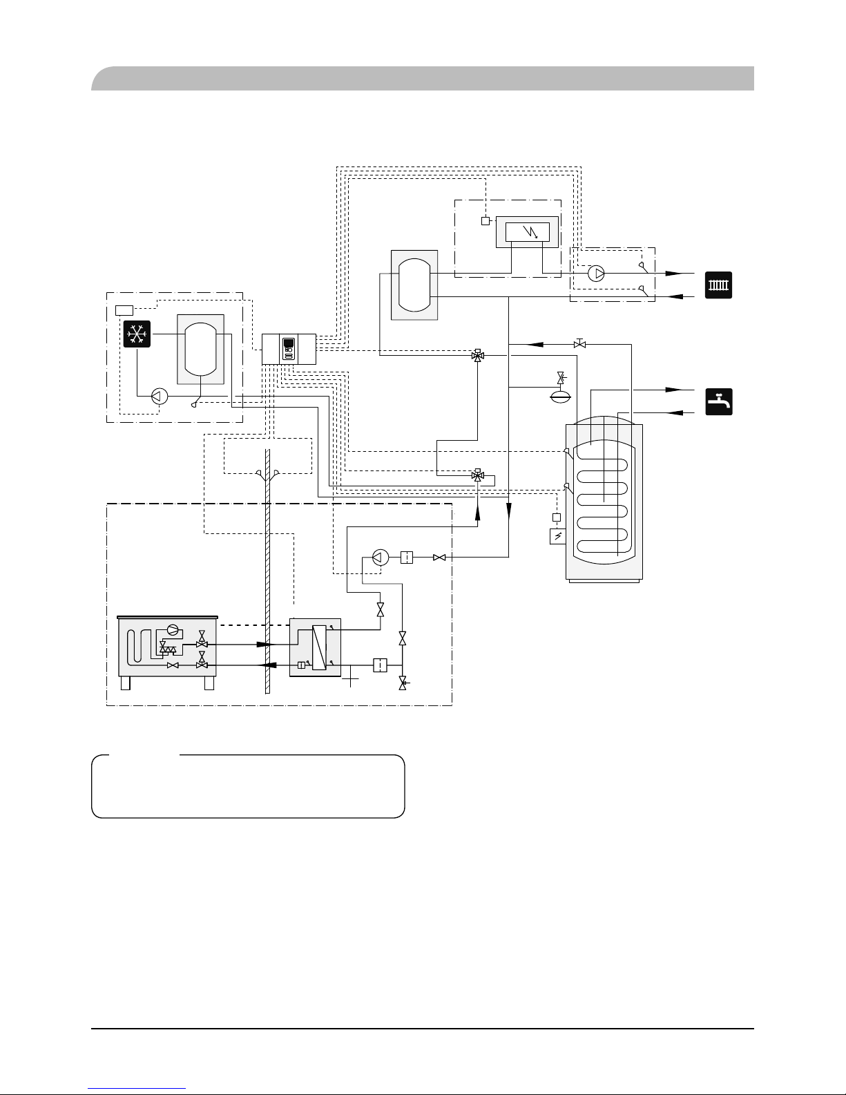
Indoor unit HSB60, tank PT300, controller RC-HY20/40 with step controlled additional heat after reversing
valve for hot water and cooling function (4 pipe system)
-EB20
-KA1
-FL2
-CM1
-EB101
-QM43
-GP12
-EB101
-HQ1
-BT1
-AA25
-AA25 -AA25
-RN10
-CP10
-AA25-QN10
-AA25-BT7
-AA25-BT6
-BT25
-EB1
-CP5
-GP10
-KA1
-BT71
-EB1
-AA25
-GP13
-BT64
-EQ1-QN12
-EQ1
-BT50
-CP6-CP6
-QM1
-EZ101
-BT12
-BT3
-BT15
-BP4
-FL10
-QM31
-QM32
-HQ1
-XL14
-XL13
-XL1
-XL2
-AA25
-EZ102
NOTE
Not all components are shown in this
outl ine di agram.
This installations alternative is suitable for more complex
installations with a focus on comfort.
Controller (AA25) starts and stops the heat pump (EB101) to
meet the heating and hot water demand of the installation.
At simultaneous heating and hot water demand the reversing
valve (AA25-QN10) switches periodically between the climate
system and the water heater/accumulator tank (CP10). When
the hot water heater/accumulator tank is fully charged, the
reversing valve switches to the climate system.
Additional heat (EB1) is turned on, automatically when the
heating demand exceeds the heat pump capacity.
Immersion heater (EB20) in the water heater/accumulator tank
is used during the time to produce hot water if the heat pump is
used for heating at the same time.
The immersion heater (EB20) can also be used if a higher
temperature of hot water is required than the heat pump can
produce.
During cooling operation, the reversing valve (EQ1-QN12)
switches to the cooling system (EQ1). If several simultaneous
demands occur while there is a cooling demand, the system
reacts differently. In the event of a hot water demand, the
reversing valve switches back and hot water is produced until
the demand is fulfi lled. In the event of a heating demand, the
reversing valve switches periodically between cooling and
heating. If the cooling demand is met, the reversing valve
switches back to basic mode (heating/hot water).
28
Pipe installation
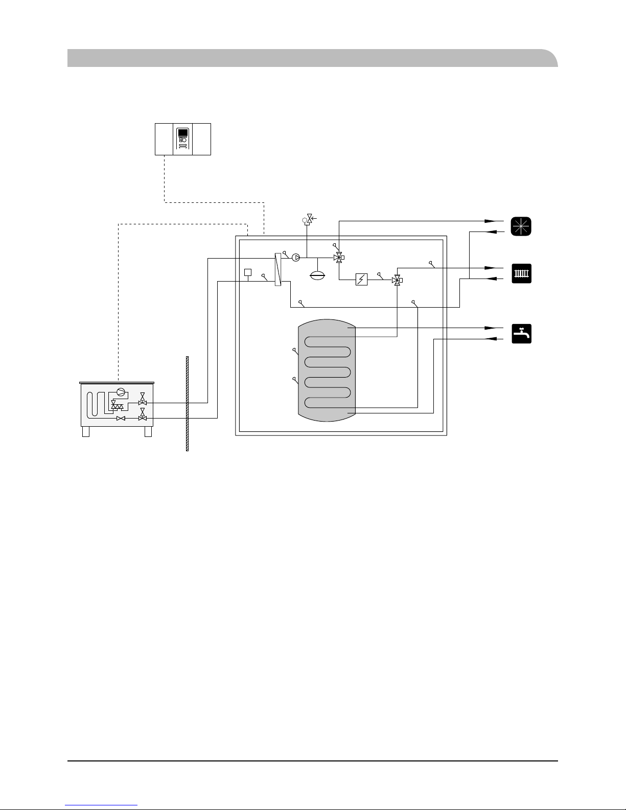
Installation with indoor unit HMK60 for hot water and cooling function (4 pipe system)
P
XL14
XL13
-BP4
-BT15
-BT3
-CM1
-EB1
-BT7
-BT6
BT71
XL4
XL3
XL1
XL2
-QN10
-BT63
-BT64
-QN12
-GP12
-BT12
XL10
-BT25
AA25
-XL14
-XL13
Controller (AA25) starts and stops the heat pump (EB101) to
meet the heating and hot water demand. At simultaneous
heating and hot water demand, the reversing valve (QN10)
swithes periodically between the climate system and the hot
water heater. When the hot water heater is fully charged, the
reversing valve swithes to the climate system.
Additional heat (EB1) is turned on automatically when the
heating demand exceeds the heat pump capacity. This is used
for both heating and charging water heater.
The additional heat can also be used for water heater when a
higher temperature is required than the heat pump can produce.
Cooling is controlled by the sensor BT64, and the reversing
valve (QN12) swithes to the cooling system. If several
simultaneous demands occur while there is a cooling demands,
the system reacts differently. In the event of a hot water
demand, the reversing valve switches back and hot water is
produced until the demand is fulfi lled. In the event of heating
demand, the reversing valve switches periodically between
cooling and heating. If the cooling demand is met, the
reversing valve switches back to basic mode (heating/hot
water).
 Loading...