

Mitsubishi Heavy Industries FDTVA151HEN1R, FDTCVA151HEN1R, FDTCVA201HEN1R, FDTCVA302HENP1R, FDTCVA402HENP2R Technical Manual
...
Manual No. '07·PAC-T-115
T E C H N I C A L M A N U A L
C o l l e c t i o n d a t a
PACKAGED AIR-CONDITIONER
MULTI-TYPE (V-MULTI)
PACKAGED AIR-CONDITIONER
(Split system, Air to air heat pump type)
CEILING RECESSED COMPACT TYPE
CEILING RECESSED TYPE
WALL MOUNTED TYPE
CEILING SUSPENDED TYPE
FDTCVA151HEN1R
201HEN1R
(OUTDOOR UNIT)
FDCVA302HENR
402HENAR
402HESAR
502HENAR
502HESAR
602HENAR
602HESAR
802HESAR
1002HESAR
FDTA151R
201R
251R
301R
401R
501R
(INDOOR UNIT)
FDTCA151R
201R
FDTCVA302HENP1R
402HENP2R
402HESP2R
FDTCVA602HENT2R
602HEST2R
FDTVA151HEN1R
201HEN1R
251HEN1R
302HEN1R
402HEN2R
402HES2R
502HEN2R
502HES2R
602HEN2R
602HES2R
FDTVA302HENP1R
402HENP2R
402HESP2R
502HENP2R
502HESP2R
602HENP2R
602HESP2R
802HESP2R
1002HESP2R
FDTVA602HENT2R
602HEST2R
802HEST2R
FDTVA802HESD2R
1002HESD2R
FDKNVA151HEN1R
201HEN1R
251HEN1R
FDKNVA302HENP1R
402HENP2R
402HESP2R
502HENP2R
502HESP2R
FDKNVA602HENT2R
602HEST2R
FDENVA151HEN1R
201HEN1R
251HEN1R
302HEN1R
402HEN2R
402HES2R
502HEN2R
502HES2R
602HEN2R
602HES2R
FDENVA302HENP1R
402HENP2R
402HESP2R
502HENP2R
502HESP2R
602HENP2R
602HESP2R
802HESP2R
1002HESP2R
FDENVA602HENT2R
602HEST2R
802HEST2R
SATELLITE DUCTED TYPE
FDUMVA201HEN2R
251HEN2R
302HEN2R
402HEN2R
402HES2R
502HEN2R
502HES2R
602HEN2R
602HES2R
FDUMVA402HENP2R
402HESP2R
502HENP2R
502HESP2R
602HENP2R
602HESP2R
802HESP2R
1002HESP2R
FDUMVA602HENT2R
602HEST2R
802HEST2R
FDENA151R
201R
251R
301R
401R
501R
FDKNA151R
201R
251R
FDUMA202R
252R
302R
402R
502R
HIGH STATIC PRESSURE DUCT TYPE
FDUVA802HES2R
1002HES2R

-
1
-
TABLE OF CONTENTS
1. PACKAGED AIR-CONDITIONER .................................................................................... 2
2. MULTI-TYPE (V MULTI) PACKAGED AIR-CONDITIONER ........................................ 291
3. WIRELESS KIT (OPTIONAL PARTS) ..........................................................................318

-
2
-
1. PACKAGED AIR-CONDITIONER
CONTENTS
1.1 GENERAL INFORMATION ...........................................................................................4
1.1.1 Specifi c features ......................................................................................................4
1.1.2 How to read the model name ................................................................................... 4
1.2 SELECTION DATA ........................................................................................................ 5
1.2.1 Specifications .......................................................................................................... 5
(1) Ceiling recessed compact type (FDTC) ................................................................... 5
(2) Ceiling recessed type (FDT) .................................................................................. 12
(3) Ceiling suspended type (FDEN) ............................................................................36
(4) Satellite ducted type (FDUM) .................................................................................58
(5) High static pressure duct type (FDU) .....................................................................78
(6) Wall mounted type (FDKN) .................................................................................... 80
1.2.2 Range of usage & limitations ................................................................................. 90
1.2.3 Exterior dimensions ............................................................................................... 93
(1) Indoor unit .............................................................................................................. 93
(2) Remote controller (Optional parts) ......................................................................105
(3) Outdoor unit ......................................................................................................... 107
1.2.4 Inside view ........................................................................................................... 113
1.2.5 Exterior appearance ............................................................................................116
1.2.6 Piping system ......................................................................................................119
1.2.7 Selection chart ..................................................................................................... 126
1.2.8 Characteristics of fan ........................................................................................... 137
1.2.9 Noise level ........................................................................................................... 140
(1) Indoor unit ............................................................................................................ 140
(2) Outdoor unit ......................................................................................................... 143
1.3 ELECTRICAL DATA .................................................................................................. 144
1.3.1 Electrical wiring .................................................................................................... 144
(1) Indoor unit ............................................................................................................ 144
(2) Outdoor unit ......................................................................................................... 151
1.4 OUTLINE OF OPERATION CONTROL BY MICROCOMPUTER ............................. 156
(1) Remote controller ................................................................................................ 156
(2) Operation control function by the indoor controller .............................................. 158
(3) Operation control function by the wired remote controller ...................................165

-
3
-
(4) Operation control function by the outdoor controller ............................................ 166
♦ Models FDCVA151 ~ 251 ..................................................................................... 166
♦ Models FDCVA302 ~ 1002 ................................................................................... 172
1.5 APPLICATION DATA ................................................................................................ 184
1.5.1 Installation of indoor unit ...................................................................................... 185
(1) Ceiling recessed compact type (FDTC) ............................................................... 185
(2) Ceiling recessed type (FDT) ................................................................................ 190
(3) Ceiling suspended type (FDEN) .........................................................................196
(4) Wall mounted type (FDKN) .................................................................................. 200
(5) Satellite ducted type (FDUM) ...............................................................................203
(6) High static pressure duct type (FDU) ...................................................................209
1.5.2 Installation of wired remote controller .................................................................. 213
1.5.3 Installation of outdoor unit .................................................................................... 214
(1) Haulage and installation ...................................................................................... 214
(2) Refrigerant piping work ........................................................................................ 216
(3) Air tightness test and air purge ............................................................................ 222
(4) Refrigerant charge ............................................................................................... 223
(5) Drain piping work ................................................................................................. 224
(6) Electrical wiring .................................................................................................... 224
(7) Setting functions using the wired remote controller ............................................. 227
(8) Checking operation data ...................................................................................... 232
(9) Test run ................................................................................................................ 233
1.6 MAINTENANCE DATA .............................................................................................. 236
1.6.1 Servicing ............................................................................................................. 236
1.6.2 Trouble shooting for refrigerant circuit .................................................................. 237
1.6.3 Diagnosing of microcomputer circuit .................................................................... 238
(1) Selfdiagnosis function .......................................................................................... 238
(2) Procedures of trouble diagnosis ..........................................................................241
(3) Error diagnosis procedures at the indoor unit side ..............................................241
(4) Error diagnosis procedures at the outdoor unit side ............................................ 259
(5) Inspection procedure for the failure which doesn’t have an error code ................ 288
(6) Check anomalous operation data with the wired remote controller ..................... 289
1.6.4 Check display on wireless specifi cation models (FDEN · FDKN· FDT) ............... 290

-
4
-
RoHS specification
: Single type
(blank)
P: Twin type
T: Triple type
D: Double twin type
Applicable power source ... See the specifications
Heat pump type
Series No.
Product capacity
R410A models
Inverter specification
Model name
Example: FDT V A 25 1 H EN P 1 R
1.1 GENERAL INFORMATION
1.1.1 Specifi c features
(1) All models employ R410A, with RoHS compliance.
(2) Industry leading COP.
Thanks to achievement of the highest COP level in the industry, the energy consumption has been cut by 24~38% compared with
our former models (constant speed models).
(3) Energy labeling “Class A”
MHI models have cleared the class A standard, the highest energy saving level, with their high COP (coeffi cient of performance).
(4) The microcomputer chip is installed in the indoor unit and outdoor unit. There is no need for the unit to communicate between the
outdoor and indoor units so the unit is more resistant to electromagnetic noise thus the incidence of microcomputer malfunction
has been reduced. The compressor in the outdoor unit has its own self protection function, that reacts according to abnormal high
pressure and excessive high temperature.
(5) There are only three power lines between the outdoor and indoor unit. One cabtyre cable with 3 wires encased in one sheath is
enough for conducting the wiring work between the outdoor unit and the indoor unit. This contributes to simpler wiring work in
the fi eld.
(6) All air supply ports have auto swing louvers. (Only case of FDTC, FDT, FDEN and FDKN models). The indoor fan motor has
three speeds of high, medium and low.
(7) All models have service valves protruding from the outdoor unit for faster fl are connection (FDCVA802, 1002: Only a gas side is
brazing) work in the field.
(8) The size and weight of the outdoor units in the FDCVA 151~251,302 Series have been greatly reduced. Use of an inverter has also
improved energy conservation and economy.
(9) Compared to the previous models, a single fan is used in the FDCVA402~602 outdoor unit models and forward blowing is used
in the FDCVA802 and FDCVA1002 models,resulting in markedly reduced weight and greater compactness.In addition, use of an
inverter makes these units much more economical compared to the previous fi xed speed units.
(10) Realization of signifi cant reduction in size and weight compared with our former models, applying front blow outlet on all models.
Reductions are 50% in weight of 6HP, 72% in volume of 8HP and 63% in the foot print of 8HP.
1.1.2 How to read the model name
FDTC :
FDT :
FDEN :
FDUM:
FDU :
FDKN :
FDC :
Ceiling recessed compact type unit
Ceiling recessed type unit
Ceiling suspended type unit
Satellite ducted type unit
High static pressure duct type unit
Wall mounted type unit
Outdoor unit
-
5
-
1.2 SELECTION DATA
1.2.1 Specifications
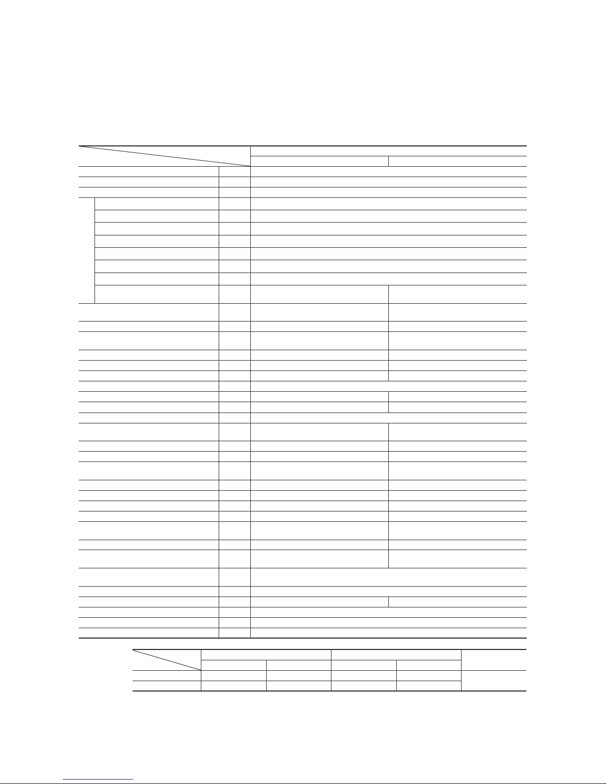
(1) Ceiling recessed compact type (FDTC)
(a) Single type
Model FDTCVA151HEN1R
Model
Item
FDTCVA151HEN1R
FDTCA151R FDCVA151HENR
Nominal cooling capacity
(1)
kW
4.0 [1.8~4.7]
Nominal heating capacity
(1)
kW
4.5 [2.0~5.4]
Power source 1 Phase, 220-240V 50Hz/220V 60Hz
Operation data
(3)
Cooling power consumption kW
1.22/1.22
Running current (Cooling) A
5.4/5.6
Power factor (Cooling) %
98/99
Heating power consumption kW
1.32/1.32
Running current (Heating) A
5.9/6.2
Power factor (Heating) %
97/97
Inrush current (L.R.A) A
5
Noise level dB(A)
Powerful mode Hi:46 Me:42 Lo:38
Mild mode Hi:42 Me:38 Lo:35
48
Exterior dimensions
Height × Width × Depth
mm
Unit 248 × 570 × 570
Panel 35 × 700 × 700
595 × 780 (+67) × 290
Net weight kg 19.5 (Unit:16 Panel:3.5) 40
Refrigerant equipment
Compressor type & Q’ty
–
5CS102XFD × 1
Starting method – Direct line start
Heat exchanger
Louver fin & inner grooved tubing Straight fin & inner grooved tubing
Refrigerant control – Electronic expansion valve
Refrigerant R410A
Quantity kg –
1.55 [Pre-charged up to the piping length of 30m]
Refrigerant oil
r
–
0.48 (RB68A)
Defrost control Microcomputer controlled de-icer
Air handling equipment
Fan type & Q’ty
Turbo fan × 1 Propeller fan × 1
Motor W 50 × 134 × 1
Starting method Direct line start Direct line start
Air fl ow CMM
Powerful mode Hi:13.5 Me:11.5 Lo:10
Mild mode Hi:11.5 Me:10 Lo:8
41
Outside air intake
Impossibility –
Air filter, Q’ty Plastic net (washable) × 1 –
Shock & vibration absorber Rubber sleeve (for fan motor) Rubber mount (for compressor)
Electric heater W – 20 (Crank case heater)
Operation control
Operation switch
Wired remote control switch (Optional : RC-E1R)
Wireless kit (Optional : RCND-KIT-HER)
– (Indoor unit side)
Room temperature control Thermostat by electronics –
Safety equipment
Internal thermostat for fan motor.
Frost protection thermostat.
Internal thermostat for fan motor.
Anomalous discharge temperature protection.
Installation data
Refrigerant piping size
mm
(in)
Liquid line: φ6.35 (1/4″) Gas line: φ12.7 (1/2″)
Connecting method Flare piping
Drain hose
Connectable with VP25 (I.D. 25mm, O.D. 32mm) –
Insulation for piping Necessary (both Liquid & Gas lines)
Accessories Mounting kit. Drain hose
Optional parts Decorative Panel (TC-PSA-24W-ER)
Notes (1) The data are measured at the following conditions.
Item
Operation
Indoor air temperature Outdoor air temperature
Standards
DB WB DB WB
Cooling 27˚C 19˚C 35˚C 24˚C
ISO-T1
Heating 20˚C – 7˚C 6˚C
(2) This packaged air-conditioner is manufactured and tested in conformity with the following standard. ISO-T1 “UNITARY AIR-CONDITIONERS”
(3) The operation data indicate when the air-conditioner is operated at 230V 50Hz or 220V 60Hz.
(4) Values in [ ~ ] show the minimum to maximum range.

-
6
-
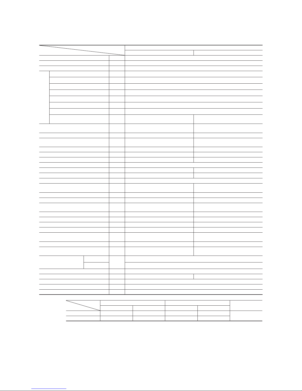
Model FDTCVA201HEN1R
Model
Item
FDTCVA201HEN1R
FDTCA201R FDCVA201HENR
Nominal cooling capacity
(1)
kW
5.0 [2.2~5.6]
Nominal heating capacity
(1)
kW
5.4 [2.5~6.3]
Power source 1 Phase, 220-240V 50Hz/220V 60Hz
Operation data
(3)
Cooling power consumption kW
1.62 /1.62
Running current (Cooling) A
7.1/7.5
Power factor (Cooling) %
99/98
Heating power consumption kW
1.53/1.53
Running current (Heating) A
6.7/7.0
Power factor (Heating) %
99/99
Inrush current (L.R.A) A
5
Noise level dB(A)
Powerful mode Hi:46 Me:42 Lo:38
Mild mode Hi:42 Me:38 Lo:35
48
Exterior dimensions
Height × Width × Depth
mm
Unit 248 × 570 × 570
Panel 35 × 700 × 700
595 × 780 (+67) × 290
Net weight kg 19.5 (Unit:16 Panel:3.5) 40
Refrigerant equipment
Compressor type & Q’ty
–
5CS102XFD × 1
Starting method – Direct line start
Heat exchanger
Louver fin & inner grooved tubing Straight fin & inner grooved tubing
Refrigerant control – Electronic expansion valve
Refrigerant R410A
Quantity kg –
1.55 [Pre-charged up to the piping length of 30m]
Refrigerant oil
r
–
0.48 (RB68A)
Defrost control Microcomputer controlled de-icer
Air handling equipment
Fan type & Q’ty
Turbo fan × 1 Propeller fan × 1
Motor W 50 × 134 × 1
Starting method Direct line start Direct line start
Air fl ow CMM
Powerful mode Hi:13.5 Me:11.5 Lo:10
Mild mode Hi:11.5 Me:10 Lo:8
41
Outside air intake
Impossibility –
Air filter, Q’ty Plastic net (washable) × 1 –
Shock & vibration absorber Rubber sleeve (for fan motor) Rubber mount (for compressor)
Electric heater W – 20 (Crank case heater)
Operation control
Operation switch
Wired remote control switch (Optional : RC-E1R)
Wireless kit (Optional : RCND-KIT-HER)
– (Indoor unit side)
Room temperature control Thermostat by electronics –
Safety equipment
Internal thermostat for fan motor.
Frost protection thermostat.
Internal thermostat for fan motor.
Anomalous discharge temperature protection.
Installation data
Refrigerant piping size
mm
(in)
Liquid line: φ6.35 (1/4″) Gas line: φ12.7 (1/2″)
Connecting method Flare piping
Drain hose
Connectable with VP25 (I.D. 25mm, O.D. 32mm) –
Insulation for piping Necessary (both Liquid & Gas lines)
Accessories Mounting kit. Drain hose
Optional parts Decorative Panel (TC-PSA-24W-ER)
Notes (1) The data are measured at the following conditions.
Item
Operation
Indoor air temperature Outdoor air temperature
Standards
DB WB DB WB
Cooling 27˚C 19˚C 35˚C 24˚C
ISO-T1
Heating 20˚C – 7˚C 6˚C
(2) This packaged air-conditioner is manufactured and tested in conformity with the following standard. ISO-T1 “UNITARY AIR-CONDITIONERS”
(3) The operation data indicate when the air-conditioner is operated at 230V 50Hz or 220V 60Hz.
(4) Values in [ ~ ] show the minimum to maximum range.

-
7
-
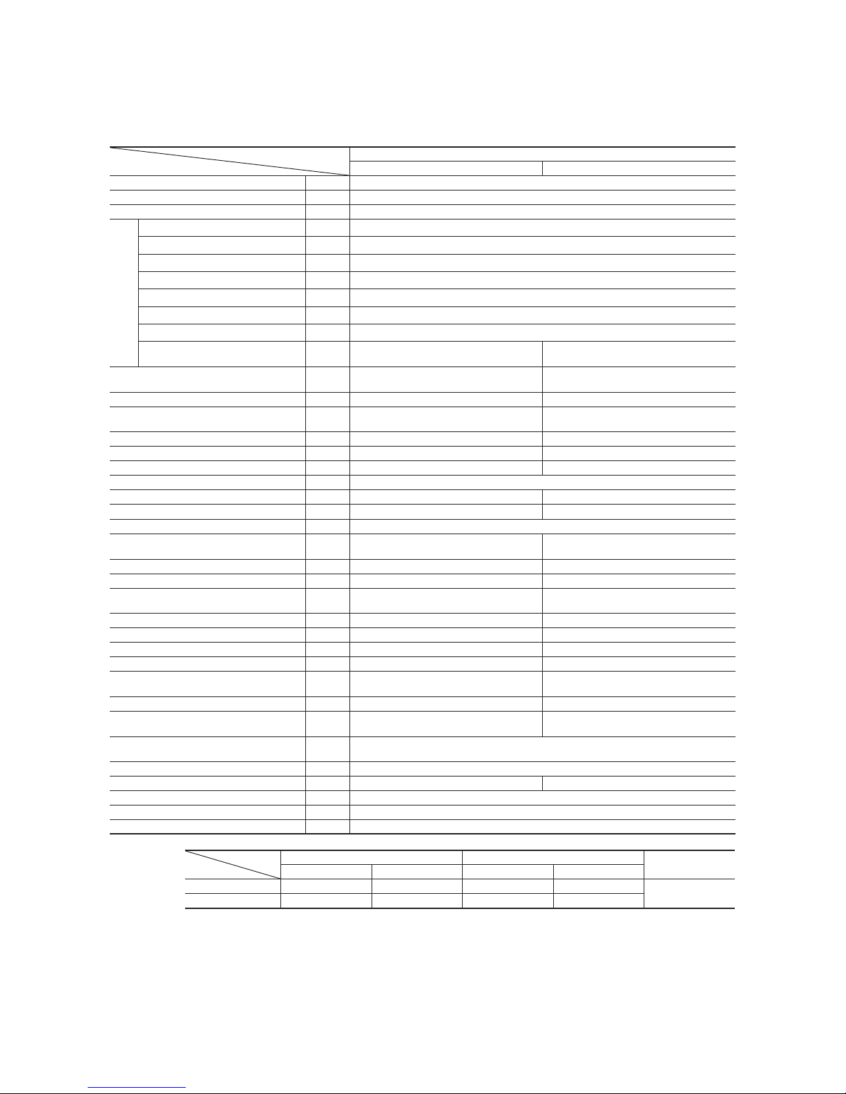
(b) Twin type
Model FDTCVA302HENP1R (Indoor unit: 2 units, Outdoor unit: 1 unit)
Model
Item
FDTCVA302HENP1R
FDTCA151R FDCVA302HENR
Nominal cooling capacity
(1)
kW
7.1[3.9~8.0]
Nominal heating capacity
(1)
kW
8.0[4.0~9.0]
Power source 1 Phase, 220-240V 50Hz/220V 60Hz
Operation data
(3)
Cooling power consumption kW
1.91/1.91
Running current (Cooling) A
8.3/8.8
Power factor (Cooling) %
99/99
Heating power consumption kW
2.08/2.08
Running current (Heating) A
9.0/9.6
Power factor (Heating) %
99/98
Inrush current (L.R.A) A
5
Noise level dB(A)
Powerful mode Hi:46 Me:42 Lo:38
Mild mode Hi:42 Me:38 Lo:35
48
Exterior dimensions
Height × Width × Depth
mm
Unit 248 × 570 × 570
Panel 35 × 700 × 700
750 × 880 (+88) × 340
Net weight kg 19.5 (Unit:16 Panel:3.5) 60
Refrigerant equipment
Compressor type & Q’ty
–
2YC45DXD × 1
Starting method – Direct line start
Heat exchanger
Louver fin & inner grooved tubing Straight fin & inner grooved tubing
Refrigerant control – Electronic expansion valve
Refrigerant R410A
Quantity kg –
2.95 [Pre-charged up to the piping length of 30m]
Refrigerant oil
r
–
0.65 (FVC50K)
Defrost control Microcomputer controlled de-icer
Air handling equipment
Fan type & Q’ty
Turbo fan × 1 Propeller fan × 1
Motor W 50 × 1120 × 1
Starting method Direct line start
Air fl ow CMM
Powerful mode Hi:13.5 Me:11.5 Lo:10
Mild mode Hi:11.5 Me:10 Lo:8
Cooling:60 Heating:48.5
Outside air intake
Available –
Air filter, Q’ty Plastic net (washable) × 1 –
Shock & vibration absorber Rubber sleeve (for fan motor) Rubber mount (for compressor)
Electric heater W – 20 (Crank case heater)
Operation control
Operation switch
Wired remote control switch (Optional : RC-E1R)
Wireless kit (Optional : RCND-KIT-HER)
– (Indoor unit side)
Room temperature control Thermostat by electronics –
Safety equipment
Internal thermostat for fan motor.
Frost protection thermostat.
Internal thermostat for fan motor.
Anomalous discharge temperature protection.
Installation data
Refrigerant piping size
Liquid line
mm
(in)
Indoor branch pipe, Outdoor main pipe: φ9.52 (3/8″)
Gas line Indoor branch pipe: φ12.7 (1/2″), Outdoor main pipe: φ15.88 (5/8″)
Connecting method Flare piping
Drain hose
Connectable with VP25 (I.D. 25mm, O.D. 32mm) –
Insulation for piping Necessary (both Liquid & Gas lines)
Accessories Mounting kit. Drain hose
Optional parts Decorative Panel (TC-PSA-24W-ER)
Notes (1) The data are measured at the following conditions.
Item
Operation
Indoor air temperature Outdoor air temperature
Standards
DB WB DB WB
Cooling 27˚C 19˚C 35˚C 24˚C
ISO-T1
Heating 20˚C – 7˚C 6˚C
(2) This packaged air-conditioner is manufactured and tested in conformity with the following standard. ISO-T1 “UNITARY AIR-CONDITIONERS”
(3) The operation data indicate when the air-conditioner is operated at 230V 50Hz or 220V 60Hz.
(4) Values in [ ~ ] show the minimum to maximum range.
(5) Indoor unit specifications show the specifications for one unit. Capacity and running characteristics values are shown for the case where two indoor
units are combined and run together.

-
8
-
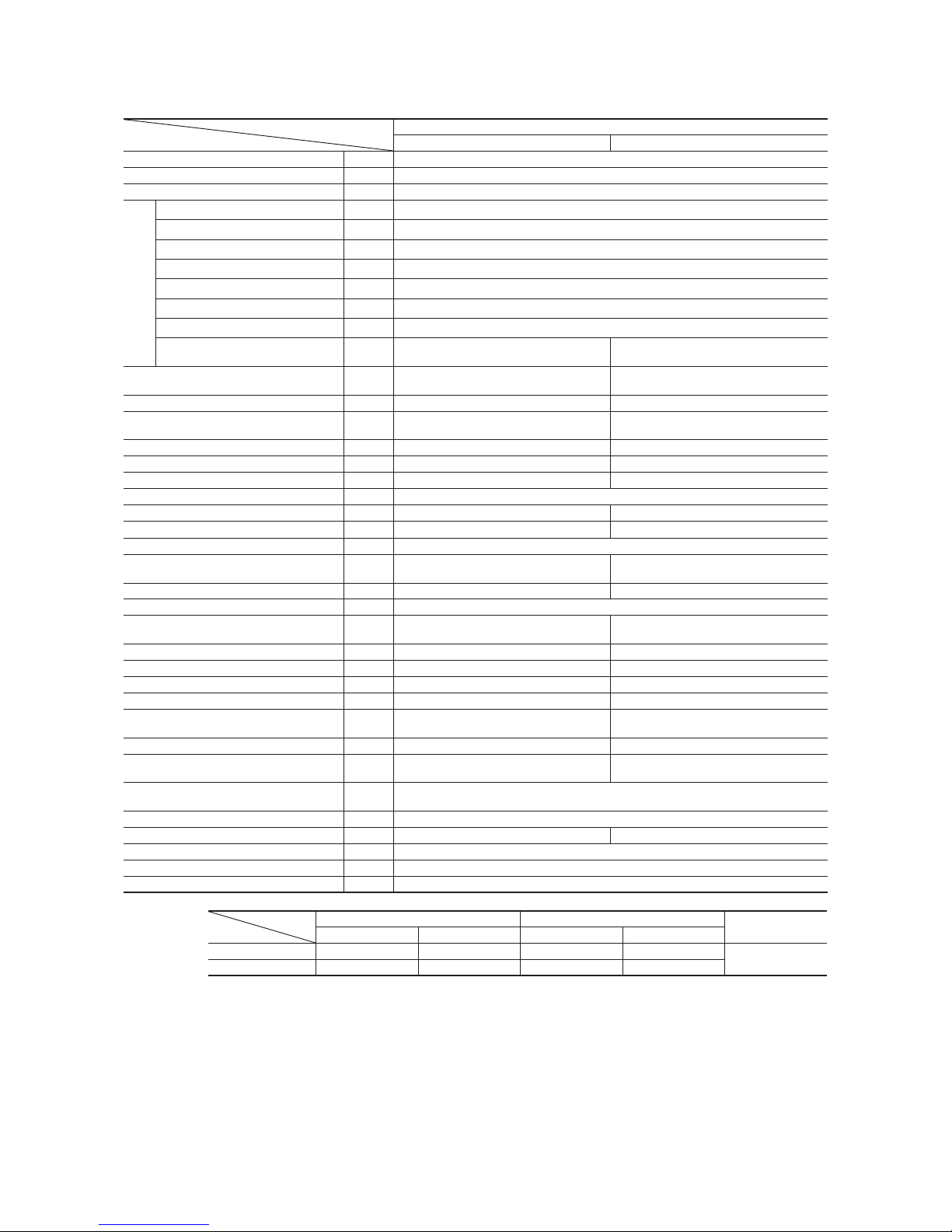
Model FDTCVA402HENP2R (Indoor unit: 2 units, Outdoor unit: 1 unit)
Model
Item
FDTCVA402HENP2R
FDTCA201R FDCVA402HENAR
Nominal cooling capacity
(1)
kW
10.0 [6.1~11.2]
Nominal heating capacity
(1)
kW
11.2 [5.6~12.5]
Power source 1 Phase, 220-240V 50Hz/220V 60Hz
Operation data
(3)
Cooling power consumption kW
2.84/2.84
Running current (Cooling) A
12.4/13.0
Power factor (Cooling) %
99/99
Heating power consumption kW
3.08/3.08
Running current (Heating) A
13.5/14.1
Power factor (Heating) %
99/99
Inrush current (L.R.A) A
5
Noise level dB(A)
Powerful mode Hi:46 Me:42 Lo:38
Mild mode Hi:42 Me:38 Lo:35
50
Exterior dimensions
Height × Width × Depth
mm
Unit 248 × 570 × 570
Panel 35 × 700 × 700
845 × 970 × 370
Net weight kg 19.5 (Unit:16 Panel:3.5) 74
Refrigerant equipment
Compressor type & Q’ty
–
RM-B5125MDE21 × 1
Starting method – Direct line start
Heat exchanger
Louver fin & inner grooved tubing Straight fin & inner grooved tubing
Refrigerant control – Electronic expansion valve
Refrigerant R410A
Quantity kg –
3.8 [Pre-charged up to the piping length of 30m]
Refrigerant oil
r
–
0.7 (M-MA68)
Defrost control Microcomputer controlled de-icer
Air handling equipment
Fan type & Q’ty
Turbo fan × 1 Propeller fan × 1
Motor W 50 × 1120 × 1
Starting method Direct line start Direct line start
Air fl ow CMM
Powerful mode Hi:13.5 Me:11.5 Lo:10
Mild mode Hi:11.5 Me:10 Lo:8
Cooling:75, Heating:73
Outside air intake
Available –
Air filter, Q’ty Plastic net (washable) × 1 –
Shock & vibration absorber Rubber sleeve (for fan motor) Rubber mount (for compressor)
Electric heater W – 20 (Crank case heater)
Operation control
Operation switch
Wired remote control switch (Optional : RC-E1R)
Wireless kit (Optional : RCND-KIT-HER)
– (Indoor unit side)
Room temperature control Thermostat by electronics –
Safety equipment
Internal thermostat for fan motor.
Frost protection thermostat.
Internal thermostat for fan motor.
Anomalous discharge temperature protection.
Installation data
Refrigerant piping size
Liquid line
mm
(in)
Indoor branch pipe, Outdoor main pipe: φ9.52 (3/8″)
Gas line Indoor branch pipe: φ12.7 (1/2″), Outdoor main pipe: φ15.88 (5/8″)
Connecting method Flare piping
Drain hose
Connectable with VP25 (I.D. 25mm, O.D. 32mm) –
Insulation for piping Necessary (both Liquid & Gas lines)
Accessories Mounting kit. Drain hose
Optional parts Decorative Panel (TC-PSA-24W-ER)
Notes (1) The data are measured at the following conditions.
Item
Operation
Indoor air temperature Outdoor air temperature
Standards
DB WB DB WB
Cooling 27˚C 19˚C 35˚C 24˚C
ISO-T1
Heating 20˚C – 7˚C 6˚C
(2) This packaged air-conditioner is manufactured and tested in conformity with the following standard. ISO-T1 “UNITARY AIR-CONDITIONERS”
(3) The operation data indicate when the air-conditioner is operated at 230V 50Hz or 220V 60Hz.
(4) Values in [ ~ ] show the minimum to maximum range.
(5) Indoor unit specifications show the specifications for one unit. Capacity and running characteristics values are shown for the case where two indoor
units are combined and run together.

-
9
-
Model FDTCVA402HESP2R (Indoor unit: 2 units, Outdoor unit: 1 unit)
Model
Item
FDTCVA402HESP2R
FDTCA201R FDCVA402HESAR
Nominal cooling capacity
(1)
kW
10.0 [6.1~11.2]
Nominal heating capacity
(1)
kW
11.2 [5.6~12.5]
Power source 3 Phase, 380-415V 50Hz/380V 60Hz
Operation data
(3)
Cooling power consumption kW
2.84/2.84
Running current (Cooling) A
4.2/4.4
Power factor (Cooling) %
98/98
Heating power consumption kW
3.08/3.08
Running current (Heating) A
4.5/4.8
Power factor (Heating) %
99/97
Inrush current (L.R.A) A
5
Noise level dB(A)
Powerful mode Hi:46 Me:42 Lo:38
Mild mode Hi:42 Me:38 Lo:35
50
Exterior dimensions
Height × Width × Depth
mm
Unit 248 × 570 × 570
Panel 35 × 700 × 700
845 × 970 × 370
Net weight kg 19.5 (Unit:16 Panel:3.5) 74
Refrigerant equipment
Compressor type & Q’ty
–
RM-B5125MDE31 × 1
Starting method – Direct line start
Heat exchanger
Louver fin & inner grooved tubing Straight fin & inner grooved tubing
Refrigerant control – Electronic expansion valve
Refrigerant R410A
Quantity kg –
3.8 [Pre-charged up to the piping length of 30m]
Refrigerant oil
r
–
0.7 (M-MA68)
Defrost control Microcomputer controlled de-icer
Air handling equipment
Fan type & Q’ty
Turbo fan × 1 Propeller fan × 1
Motor W 50 × 1120 × 1
Starting method Direct line start Direct line start
Air fl ow CMM
Powerful mode Hi:13.5 Me:11.5 Lo:10
Mild mode Hi:11.5 Me:10 Lo:8
Cooling:75, Heating:73
Outside air intake
Available –
Air filter, Q’ty Plastic net (washable) × 1 –
Shock & vibration absorber Rubber sleeve (for fan motor) Rubber mount (for compressor)
Electric heater W – 20 (Crank case heater)
Operation control
Operation switch
Wired remote control switch (Optional : RC-E1R)
Wireless kit (Optional : RCND-KIT-HER)
– (Indoor unit side)
Room temperature control Thermostat by electronics –
Safety equipment
Internal thermostat for fan motor.
Frost protection thermostat.
Internal thermostat for fan motor.
Anomalous discharge temperature protection.
Installation data
Refrigerant piping size
Liquid line
mm
(in)
Indoor branch pipe, Outdoor main pipe: φ9.52 (3/8″)
Gas line Indoor branch pipe: φ12.7 (1/2″), Outdoor main pipe: φ15.88 (5/8″)
Connecting method Flare piping
Drain hose
Connectable with VP25 (I.D. 25mm, O.D. 32mm) –
Insulation for piping Necessary (both Liquid & Gas lines)
Accessories Mounting kit. Drain hose
Optional parts Decorative Panel (TC-PSA-24W-ER)
Notes (1) The data are measured at the following conditions.
Item
Operation
Indoor air temperature Outdoor air temperature
Standards
DB WB DB WB
Cooling 27˚C 19˚C 35˚C 24˚C
ISO-T1
Heating 20˚C – 7˚C 6˚C
(2) This packaged air-conditioner is manufactured and tested in conformity with the following standard. ISO-T1 “UNITARY AIR-CONDITIONERS”
(3) The operation data indicate when the air-conditioner is operated at 400V 50Hz or 380V 60Hz.
(4) Values in [ ~ ] show the minimum to maximum range.
(5) Indoor unit specifications show the specifications for one unit. Capacity and running characteristics values are shown for the case where two indoor
units are combined and run together.
-
10
-
(c) Triple type
Model FDTCVA602HENT2R (Indoor unit: 3 units, Outdoor unit: 1 unit)
Model
Item
FDTCVA602HENT2R
FDTCA201R FDCVA602HENAR
Nominal cooling capacity
(1)
kW
14.0 [6.7~14.8]
Nominal heating capacity
(1)
kW
16.0 [6.3~16.8]
Power source 1 Phase, 220-240V 50Hz/220V 60Hz
Operation data
(3)
Cooling power consumption kW
4.64/4.64
Running current (Cooling) A
20.4/21.3
Power factor (Cooling) %
99/99
Heating power consumption kW
4.52/4.52
Running current (Heating) A
20.0/20.9
Power factor (Heating) %
98/98
Inrush current (L.R.A) A
5
Noise level dB(A)
Powerful mode Hi:46 Me:42 Lo:38
Mild mode Hi:42 Me:38 Lo:35
53
Exterior dimensions
Height × Width × Depth
mm
Unit 248 × 570 × 570
Panel 35 × 700 × 700
845 × 970 × 370
Net weight kg 19.5 (Unit:16 Panel:3.5) 74
Refrigerant equipment
Compressor type & Q’ty
–
RM-B5125MD11 × 1
Starting method – Direct line start
Heat exchanger
Louver fin & inner grooved tubing Straight fin & inner grooved tubing
Refrigerant control – Electronic expansion valve
Refrigerant R410A
Quantity kg –
3.8 [Pre-charged up to the piping length of 30m]
Refrigerant oil
r
–
0.7 (M-MA68)
Defrost control Microcomputer controlled de-icer
Air handling equipment
Fan type & Q’ty
Turbo fan × 1 Propeller fan × 1
Motor W 50 × 1120 × 1
Starting method Direct line start Direct line start
Air fl ow CMM
Powerful mode Hi:13.5 Me:11.5 Lo:10
Mild mode Hi:11.5 Me:10 Lo:8
Cooling:75, Heating:73
Outside air intake
Available –
Air filter, Q’ty Plastic net (washable) × 1 –
Shock & vibration absorber Rubber sleeve (for fan motor) Rubber mount (for compressor)
Electric heater W – 20 (Crank case heater)
Operation control
Operation switch
Wired remote control switch (Optional : RC-E1R)
Wireless kit (Optional : RCND-KIT-HER)
– (Indoor unit side)
Room temperature control Thermostat by electronics –
Safety equipment
Internal thermostat for fan motor.
Frost protection thermostat.
Internal thermostat for fan motor.
Anomalous discharge temperature protection.
Installation data
Refrigerant piping size
Liquid line
mm
(in)
Indoor branch pipe, Outdoor main pipe: φ9.52 (3/8″)
Gas line Indoor branch pipe: φ12.7 (1/2″), Outdoor main pipe: φ15.88 (5/8″)
Connecting method Flare piping
Drain hose
Connectable with VP25 (I.D. 25mm, O.D. 32mm) –
Insulation for piping Necessary (both Liquid & Gas lines)
Accessories Mounting kit. Drain hose
Optional parts Decorative Panel (TC-PSA-24W-ER)
Notes (1) The data are measured at the following conditions.
Item
Operation
Indoor air temperature Outdoor air temperature
Standards
DB WB DB WB
Cooling 27˚C 19˚C 35˚C 24˚C
ISO-T1
Heating 20˚C – 7˚C 6˚C
(2) This packaged air-conditioner is manufactured and tested in conformity with the following standard. ISO-T1 “UNITARY AIR-CONDITIONERS”
(3) The operation data indicate when the air-conditioner is operated at 230V 50Hz or 220V 60Hz.
(4) Values in [ ~ ] show the minimum to maximum range.
(5) Indoor unit specifications show the specifications for one unit. Capacity and running characteristics values are shown for the case where three indoor
units are combined and run together.

-
11
-
Model FDTCVA602HEST2R (Indoor unit: 3 units, Outdoor unit: 1 unit)
Model
Item
FDTCVA602HEST2R
FDTCA201R FDCVA602HESAR
Nominal cooling capacity
(1)
kW
14.0 [6.7~14.8]
Nominal heating capacity
(1)
kW
16.0 [6.3~16.8]
Power source 3 Phase, 380-415V 50Hz/380V 60Hz
Operation data
(3)
Cooling power consumption kW
4.64/4.64
Running current (Cooling) A
6.8/7.1
Power factor (Cooling) %
98/99
Heating power consumption kW
4.52/4.52
Running current (Heating) A
6.6/7.0
Power factor (Heating) %
99/98
Inrush current (L.R.A) A
5
Noise level dB(A)
Powerful mode Hi:46 Me:42 Lo:38
Mild mode Hi:42 Me:38 Lo:35
53
Exterior dimensions
Height × Width × Depth
mm
Unit 248 × 570 × 570
Panel 35 × 700 × 700
845 × 970 × 370
Net weight kg 19.5 (Unit:16 Panel:3.5) 74
Refrigerant equipment
Compressor type & Q’ty
–
RM-B5125MDE31 × 1
Starting method – Direct line start
Heat exchanger
Louver fin & inner grooved tubing Straight fin & inner grooved tubing
Refrigerant control – Electronic expansion valve
Refrigerant R410A
Quantity kg –
3.8 [Pre-charged up to the piping length of 30m]
Refrigerant oil
r
–
0.7 (M-MA68)
Defrost control Microcomputer controlled de-icer
Air handling equipment
Fan type & Q’ty
Turbo fan × 1 Propeller fan × 1
Motor W 50 × 1120 × 1
Starting method Direct line start Direct line start
Air fl ow CMM
Powerful mode Hi:13.5 Me:11.5 Lo:10
Mild mode Hi:11.5 Me:10 Lo:8
Cooling:75, Heating:73
Outside air intake
Available –
Air filter, Q’ty Plastic net (washable) × 1 –
Shock & vibration absorber Rubber sleeve (for fan motor) Rubber mount (for compressor)
Electric heater W – 20 (Crank case heater)
Operation control
Operation switch
Wired remote control switch (Optional : RC-E1R)
Wireless kit (Optional : RCND-KIT-HER)
– (Indoor unit side)
Room temperature control Thermostat by electronics –
Safety equipment
Internal thermostat for fan motor.
Frost protection thermostat.
Internal thermostat for fan motor.
Anomalous discharge temperature protection.
Installation data
Refrigerant piping size
Liquid line
mm
(in)
Indoor branch pipe, Outdoor main pipe: φ9.52 (3/8″)
Gas line Indoor branch pipe: φ12.7 (1/2″), Outdoor main pipe: φ15.88 (5/8″)
Connecting method Flare piping
Drain hose
Connectable with VP25 (I.D. 25mm, O.D. 32mm) –
Insulation for piping Necessary (both Liquid & Gas lines)
Accessories Mounting kit. Drain hose
Optional parts Decorative Panel (TC-PSA-24W-ER)
Notes (1) The data are measured at the following conditions.
Item
Operation
Indoor air temperature Outdoor air temperature
Standards
DB WB DB WB
Cooling 27˚C 19˚C 35˚C 24˚C
ISO-T1
Heating 20˚C – 7˚C 6˚C
(2) This packaged air-conditioner is manufactured and tested in conformity with the following standard. ISO-T1 “UNITARY AIR-CONDITIONERS”
(3) The operation data indicate when the air-conditioner is operated at 400V 50Hz or 380V 60Hz.
(4) Values in [ ~ ] show the minimum to maximum range.
(5) Indoor unit specifications show the specifications for one unit. Capacity and running characteristics values are shown for the case where three indoor
units are combined and run together.
-
12
-
(2) Ceiling recessed type (FDT)
(a) Single type
Model FDTVA151HEN1R
Model
Item
FDTVA151HEN1R
FDTA151R FDCVA151HENR
Nominal cooling capacity
(1)
kW
4.0 [1.8~4.7]
Nominal heating capacity
(1)
kW
4.5 [2.0~5.4]
Power source 1 Phase, 220-240V 50Hz/220V 60Hz
Operation data
(3)
Cooling power consumption kW
1.22/1.23
Running current (Cooling) A
5.4/5.7
Power factor (Cooling) %
98/98
Heating power consumption kW
1.32/1.32
Running current (Heating) A
5.9/6.2
Power factor (Heating) %
97/97
Inrush current (L.R.A) A
5
Noise level dB(A)
Powerful mode Hi:36 Me:33 Lo:32
Mild mode Hi:33 Me:32 Lo:31
48
Exterior dimensions
Height × Width × Depth
mm
Unit 270 × 840 × 840
Panel 35 × 950 × 950
595 × 780 (+67) × 290
Net weight kg 31 (Unit:24 Panel:7) 40
Refrigerant equipment
Compressor type & Q’ty
–
5CS102XFD × 1
Starting method – Direct line start
Heat exchanger
Louver fin & inner grooved tubing Straight fin & inner grooved tubing
Refrigerant control – Electronic expansion valve
Refrigerant R410A
Quantity kg –
1.55 [Pre-charged up to the piping length of 30m]
Refrigerant oil
r
–
0.48 (RB68A)
Defrost control Microcomputer controlled de-icer
Air handling equipment
Fan type & Q’ty
Turbo fan × 1 Propeller fan × 1
Motor W 14 × 134 × 1
Starting method Direct line start Direct line start
Air fl ow CMM
Powerful mode Hi:18 Me:15 Lo:14
Mild mode Hi:15 Me:14 Lo:13
41
Outside air intake
Available –
Air filter, Q’ty Plastic net (washable) × 1 –
Shock & vibration absorber Rubber sleeve (for fan motor) Rubber mount (for compressor)
Electric heater W – 20 (Crank case heater)
Operation control
Operation switch
Wired remote control switch (Optional : RC-E1R)
Wireless kit (Optional : RCN-T-35W-ER)
– (Indoor unit side)
Room temperature control Thermostat by electronics –
Safety equipment
Internal thermostat for fan motor.
Frost protection thermostat.
Internal thermostat for fan motor.
Anomalous discharge temperature protection.
Installation data
Refrigerant piping size
mm
(in)
Liquid line: φ6.35 (1/4″) Gas line: φ12.7 (1/2″)
Connecting method Flare piping
Drain hose
Connectable with VP25 (I.D. 25mm, O.D. 32mm) –
Insulation for piping Necessary (both Liquid & Gas lines)
Accessories Mounting kit. Drain hose
Optional parts Decorative Panel (T-PSA-35W-ER)
Notes (1) The data are measured at the following conditions.
Item
Operation
Indoor air temperature Outdoor air temperature
Standards
DB WB DB WB
Cooling 27˚C 19˚C 35˚C 24˚C
ISO-T1
Heating 20˚C – 7˚C 6˚C
(2) This packaged air-conditioner is manufactured and tested in conformity with the following standard. ISO-T1 “UNITARY AIR-CONDITIONERS”
(3) The operation data indicate when the air-conditioner is operated at 230V 50Hz or 220V 60Hz.
(4) Values in [ ~ ] show the minimum to maximum range.

-
13
-
Model FDTVA201HEN1R
Model
Item
FDTVA201HEN1R
FDTA201R FDCVA201HENR
Nominal cooling capacity
(1)
kW
5.0 [2.2~5.6]
Nominal heating capacity
(1)
kW
5.4 [2.5~6.3]
Power source 1 Phase, 220-240V 50Hz/220V 60Hz
Operation data
(3)
Cooling power consumption kW
1.42/1.43
Running current (Cooling) A
6.3/6.6
Power factor (Cooling) %
98/98
Heating power consumption kW
1.49/1.49
Running current (Heating) A
6.6/6.9
Power factor (Heating) %
98/98
Inrush current (L.R.A) A
5
Noise level dB(A)
Powerful mode Hi:36 Me:33 Lo:32
Mild mode Hi:33 Me:32 Lo:31
48
Exterior dimensions
Height × Width × Depth
mm
Unit 270 × 840 × 840
Panel 35 × 950 × 950
595 × 780 (+67) × 290
Net weight kg 31 (Unit:24 Panel:7) 40
Refrigerant equipment
Compressor type & Q’ty
–
5CS102XFD × 1
Starting method – Direct line start
Heat exchanger
Louver fin & inner grooved tubing Straight fin & inner grooved tubing
Refrigerant control – Electronic expansion valve
Refrigerant R410A
Quantity kg –
1.55 [Pre-charged up to the piping length of 30m]
Refrigerant oil
r
–
0.48 (RB68A)
Defrost control Microcomputer controlled de-icer
Air handling equipment
Fan type & Q’ty
Turbo fan × 1 Propeller fan × 1
Motor W 14 × 134 × 1
Starting method Direct line start Direct line start
Air fl ow CMM
Powerful mode Hi:18 Me:15 Lo:14
Mild mode Hi:15 Me:14 Lo:13
41
Outside air intake
Available –
Air filter, Q’ty Plastic net (washable) × 1 –
Shock & vibration absorber Rubber sleeve (for fan motor) Rubber mount (for compressor)
Electric heater W – 20 (Crank case heater)
Operation control
Operation switch
Wired remote control switch (Optional : RC-E1R)
Wireless kit (Optional : RCN-T-35W-ER)
– (Indoor unit side)
Room temperature control Thermostat by electronics –
Safety equipment
Internal thermostat for fan motor.
Frost protection thermostat.
Internal thermostat for fan motor.
Anomalous discharge temperature protection.
Installation data
Refrigerant piping size
mm
(in)
Liquid line: φ6.35 (1/4″) Gas line: φ12.7 (1/2″)
Connecting method Flare piping
Drain hose
Connectable with VP25 (I.D. 25mm, O.D. 32mm) –
Insulation for piping Necessary (both Liquid & Gas lines)
Accessories Mounting kit. Drain hose
Optional parts Decorative Panel (T-PSA-35W-ER)
Notes (1) The data are measured at the following conditions.
Item
Operation
Indoor air temperature Outdoor air temperature
Standards
DB WB DB WB
Cooling 27˚C 19˚C 35˚C 24˚C
ISO-T1
Heating 20˚C – 7˚C 6˚C
(2) This packaged air-conditioner is manufactured and tested in conformity with the following standard. ISO-T1 “UNITARY AIR-CONDITIONERS”
(3) The operation data indicate when the air-conditioner is operated at 230V 50Hz or 220V 60Hz.
(4) Values in [ ~ ] show the minimum to maximum range.

-
14
-
Model FDTVA251HEN1R
Model
Item
FDTVA251HEN1R
FDTA251R FDCVA251HENR
Nominal cooling capacity
(1)
kW
5.6 [2.8~6.3]
Nominal heating capacity
(1)
kW
6.7 [3.1~7.1]
Power source 1 Phase, 220-240V 50Hz/220V 60Hz
Operation data
(3)
Cooling power consumption kW
1.64/1.65
Running current (Cooling) A
7.3/7.6
Power factor (Cooling) %
98/99
Heating power consumption kW
1.78/1.79
Running current (Heating) A
7.9/8.4
Power factor (Heating) %
98/97
Inrush current (L.R.A) A
5
Noise level dB(A)
Powerful mode Hi:38 Me:35 Lo:33
Mild mode Hi:35 Me:33 Lo:31
48
Exterior dimensions
Height × Width × Depth
mm
Unit 270 × 840 × 840
Panel 35 × 950 × 950
595 × 780 (+67) × 290
Net weight kg 31 (Unit:24 Panel:7) 40
Refrigerant equipment
Compressor type & Q’ty
–
5CS102XFD × 1
Starting method – Direct line start
Heat exchanger
Louver fin & inner grooved tubing Straight fin & inner grooved tubing
Refrigerant control – Electronic expansion valve
Refrigerant R410A
Quantity kg –
1.75 [Pre-charged up to the piping length of 30m]
Refrigerant oil
r
–
0.48 (RB68A)
Defrost control Microcomputer controlled de-icer
Air handling equipment
Fan type & Q’ty
Turbo fan × 1 Propeller fan × 1
Motor W 20 × 134 × 1
Starting method Direct line start Direct line start
Air fl ow CMM
Powerful mode Hi:20 Me:17 Lo:15
Mild mode Hi:17 Me:15 Lo:13
41
Outside air intake
Available –
Air filter, Q’ty Plastic net (washable) × 1 –
Shock & vibration absorber Rubber sleeve (for fan motor) Rubber mount (for compressor)
Electric heater W – 20 (Crank case heater)
Operation control
Operation switch
Wired remote control switch (Optional : RC-E1R)
Wireless kit (Optional : RCN-T-35W-ER)
– (Indoor unit side)
Room temperature control Thermostat by electronics –
Safety equipment
Internal thermostat for fan motor.
Frost protection thermostat.
Internal thermostat for fan motor.
Anomalous discharge temperature protection.
Installation data
Refrigerant piping size
mm
(in)
Liquid line: φ6.35 (1/4″) Gas line: φ15.88 (5/8″)
Connecting method Flare piping
Drain hose
Connectable with VP25 (I.D. 25mm, O.D. 32mm) –
Insulation for piping Necessary (both Liquid & Gas lines)
Accessories Mounting kit. Drain hose
Optional parts Decorative Panel (T-PSA-35W-ER)
Notes (1) The data are measured at the following conditions.
Item
Operation
Indoor air temperature Outdoor air temperature
Standards
DB WB DB WB
Cooling 27˚C 19˚C 35˚C 24˚C
ISO-T1
Heating 20˚C – 7˚C 6˚C
(2) This packaged air-conditioner is manufactured and tested in conformity with the following standard. ISO-T1 “UNITARY AIR-CONDITIONERS”
(3) The operation data indicate when the air-conditioner is operated at 230V 50Hz or 220V 60Hz.
(4) Values in [ ~ ] show the minimum to maximum range.
-
15
-
Model FDTVA302HEN1R
Model
Item
FDTVA302HEN1R
FDTA301R FDCVA302HENR
Nominal cooling capacity
(1)
kW
7.1[3.9~8.0]
Nominal heating capacity
(1)
kW
8.0[4.0~9.0]
Power source 1 Phase, 220-240V 50Hz/220V 60Hz
Operation data
(3)
Cooling power consumption kW
1.90/1.91
Running current (Cooling) A
8.3/8.8
Power factor (Cooling) %
99/99
Heating power consumption kW
2.07/2.08
Running current (Heating) A
9.0/9.6
Power factor (Heating) %
99/98
Inrush current (L.R.A) A
5
Noise level dB(A)
Powerful mode Hi:38 Me:35 Lo:33
Mild mode Hi:35 Me:33 Lo:31
48
Exterior dimensions
Height × Width × Depth
mm
Unit 270 × 840 × 840
Panel 35 × 950 × 950
750 × 880 (+88) × 340
Net weight kg 31 (Unit:24 Panel:7) 60
Refrigerant equipment
Compressor type & Q’ty
–
2YC45DXD × 1
Starting method – Direct line start
Heat exchanger
Louver fin & inner grooved tubing Straight fin & inner grooved tubing
Refrigerant control – Electronic expansion valve
Refrigerant R410A
Quantity kg –
2.95 [Pre-charged up to the piping length of 30m]
Refrigerant oil
r
–
0.65 (FVC50K)
Defrost control Microcomputer controlled de-icer
Air handling equipment
Fan type & Q’ty
Turbo fan × 1 Propeller fan × 1
Motor W 20 × 1120 × 1
Starting method Direct line start
Air fl ow CMM
Powerful mode Hi:20 Me:17 Lo:15
Mild mode Hi:17 Me:15 Lo:13
Cooling:60 Heating:48.5
Outside air intake
Available –
Air filter, Q’ty Plastic net (washable) × 1 –
Shock & vibration absorber Rubber sleeve (for fan motor) Rubber mount (for compressor)
Electric heater W – 20 (Crank case heater)
Operation control
Operation switch
Wired remote control switch (Optional : RC-E1R)
Wireless kit (Optional : RCN-T-35W-ER)
– (Indoor unit side)
Room temperature control Thermostat by electronics –
Safety equipment
Internal thermostat for fan motor.
Frost protection thermostat.
Internal thermostat for fan motor.
Anomalous discharge temperature protection.
Installation data
Refrigerant piping size
mm
(in)
Liquid line: φ9.52 (3/8″) Gas line: φ15.88 (5/8″)
Connecting method Flare piping
Drain hose
Connectable with VP25 (I.D. 25mm, O.D. 32mm) –
Insulation for piping Necessary (both Liquid & Gas lines)
Accessories Mounting kit. Drain hose
Optional parts Decorative Panel (T-PSA-35W-ER)
Notes (1) The data are measured at the following conditions.
Item
Operation
Indoor air temperature Outdoor air temperature
Standards
DB WB DB WB
Cooling 27˚C 19˚C 35˚C 24˚C
ISO-T1
Heating 20˚C – 7˚C 6˚C
(2) This packaged air-conditioner is manufactured and tested in conformity with the following standard. ISO-T1 “UNITARY AIR-CONDITIONERS”
(3) The operation data indicate when the air-conditioner is operated at 230V 50Hz or 220V 60Hz.
(4) Values in [ ~ ] show the minimum to maximum range.

-
16
-
Model FDTVA402HEN2R
Model
Item
FDTVA402HEN2R
(5)
FDTA401R FDCVA402HENAR
Nominal cooling capacity
(1)
kW
10.0 [6.1~11.2]
Nominal heating capacity
(1)
kW
11.2 [5.6~12.5]
Power source 1 Phase, 220-240V 50Hz
Operation data
(3)
Cooling power consumption kW
2.88
Running current (Cooling) A
12.6
Power factor (Cooling) %
99
Heating power consumption kW
3.12
Running current (Heating) A
13.7
Power factor (Heating) %
99
Inrush current (L.R.A) A
5
Noise level dB(A)
Powerful mode Hi:46 Me:43 Lo:41
Mild mode Hi:43 Me:41 Lo:38
50
Exterior dimensions
Height × Width × Depth
mm
Unit 295 × 840 × 840
Panel 35 × 950 × 950
845 × 970 × 370
Net weight kg 33 (Unit:26 Panel:7) 74
Refrigerant equipment
Compressor type & Q’ty
–
RM-B5125MDE21 × 1
Starting method – Direct line start
Heat exchanger
Louver fin & inner grooved tubing Straight fin & inner grooved tubing
Refrigerant control – Electronic expansion valve
Refrigerant R410A
Quantity kg –
3.8 [Pre-charged up to the piping length of 30m]
Refrigerant oil
r
–
0.7 (M-MA68)
Defrost control Microcomputer controlled de-icer
Air handling equipment
Fan type & Q’ty
Turbo fan × 1 Propeller fan × 1
Motor W 40 × 1120 × 1
Starting method Direct line start Direct line start
Air fl ow CMM
Powerful mode Hi:25 Me:22 Lo:20
Mild mode Hi:22 Me:20 Lo:18
Cooling: 75, Heating: 73
Outside air intake
Available –
Air filter, Q’ty Plastic net (washable) × 1 –
Shock & vibration absorber Rubber sleeve (for fan motor) Rubber mount (for compressor)
Electric heater W – 20 (Crank case heater)
Operation control
Operation switch
Wired remote control switch (Optional : RC-E1R)
Wireless kit (Optional : RCN-T-35W-ER)
– (Indoor unit side)
Room temperature control Thermostat by electronics –
Safety equipment
Internal thermostat for fan motor.
Frost protection thermostat.
Internal thermostat for fan motor.
Anomalous discharge temperature protection.
Installation data
Refrigerant piping size
mm
(in)
Liquid line: φ9.52 (3/8″) Gas line: φ15.88 (5/8″)
Connecting method Flare piping
Drain hose
Connectable with VP25 (I.D. 25mm, O.D. 32mm) –
Insulation for piping Necessary (both Liquid & Gas lines)
Accessories Mounting kit. Drain hose
Optional parts Decorative Panel (T-PSA-35W-ER)
Notes (1) The data are measured at the following conditions.
Item
Operation
Indoor air temperature Outdoor air temperature
Standards
DB WB DB WB
Cooling 27˚C 19˚C 35˚C 24˚C
ISO-T1
Heating 20˚C – 7˚C 6˚C
(2) This packaged air-conditioner is manufactured and tested in conformity with the following standard. ISO-T1 “UNITARY AIR-CONDITIONERS”
(3) The operation data indicate when the air-conditioner is operated at 230V 50Hz.
(4) Values in [ ~ ] show the minimum to maximum range.
(5) Not available in 60Hz.
-
17
-
Model FDTVA402HES2R
Model
Item
FDTVA402HES2R
(5)
FDTA401R FDCVA402HESAR
Nominal cooling capacity
(1)
kW
10.0 [6.1~11.2]
Nominal heating capacity
(1)
kW
11.2 [5.6~12.5]
Power source 3 Phase, 380-415V 50Hz
Operation data
(3)
Cooling power consumption kW
2.97
Running current (Cooling) A
4.7
Power factor (Cooling) %
91
Heating power consumption kW
2.92
Running current (Heating) A
4.6
Power factor (Heating) %
92
Inrush current (L.R.A) A
5
Noise level dB(A)
Powerful mode Hi:46 Me:43 Lo:41
Mild mode Hi:43 Me:41 Lo:38
50
Exterior dimensions
Height × Width × Depth
mm
Unit 295 × 840 × 840
Panel 35 × 950 × 950
845 × 970 × 370
Net weight kg 33 (Unit:26 Panel:7) 74
Refrigerant equipment
Compressor type & Q’ty
–
RM-B5125MDE31 × 1
Starting method – Direct line start
Heat exchanger
Louver fin & inner grooved tubing Straight fin & inner grooved tubing
Refrigerant control – Electronic expansion valve
Refrigerant R410A
Quantity kg –
3.8 [Pre-charged up to the piping length of 30m]
Refrigerant oil
r
–
0.7 (M-MA68)
Defrost control Microcomputer controlled de-icer
Air handling equipment
Fan type & Q’ty
Turbo fan × 1 Propeller fan × 1
Motor W 40 × 1120 × 1
Starting method Direct line start Direct line start
Air fl ow CMM
Powerful mode Hi:25 Me:22 Lo:20
Mild mode Hi:22 Me:20 Lo:18
Cooling: 75, Heating: 73
Outside air intake
Available –
Air filter, Q’ty Plastic net (washable) × 1 –
Shock & vibration absorber Rubber sleeve (for fan motor) Rubber mount (for compressor)
Electric heater W – 20 (Crank case heater)
Operation control
Operation switch
Wired remote control switch (Optional : RC-E1R)
Wireless kit (Optional : RCN-T-35W-ER)
– (Indoor unit side)
Room temperature control Thermostat by electronics –
Safety equipment
Internal thermostat for fan motor.
Frost protection thermostat.
Internal thermostat for fan motor.
Anomalous discharge temperature protection.
Installation data
Refrigerant piping size
mm
(in)
Liquid line: φ9.52 (3/8″) Gas line: φ15.88 (5/8″)
Connecting method Flare piping
Drain hose
Connectable with VP25 (I.D. 25mm, O.D. 32mm) –
Insulation for piping Necessary (both Liquid & Gas lines)
Accessories Mounting kit. Drain hose
Optional parts Decorative Panel (T-PSA-35W-ER)
Notes (1) The data are measured at the following conditions.
Item
Operation
Indoor air temperature Outdoor air temperature
Standards
DB WB DB WB
Cooling 27˚C 19˚C 35˚C 24˚C
ISO-T1
Heating 20˚C – 7˚C 6˚C
(2) This packaged air-conditioner is manufactured and tested in conformity with the following standard. ISO-T1 “UNITARY AIR-CONDITIONERS”
(3) The operation data indicate when the air-conditioner is operated at 400V 50Hz.
(4) Values in [ ~ ] show the minimum to maximum range.
(5) Not available in 60Hz.

-
18
-
Model FDTAV502HEN2R
Model
Item
FDTVA502HEN2R
FDTA501R FDCVA502HENAR
Nominal cooling capacity
(1)
kW
12.5 [6.5~14.0]
Nominal heating capacity
(1)
kW
14.0 [6.2~16.0]
Power source 1 Phase, 220-240V 50Hz/220V 60Hz
Operation data
(3)
Cooling power consumption kW
4.05/4.05
Running current (Cooling) A
17.7/18.6
Power factor (Cooling) %
99/99
Heating power consumption kW
3.97/3.97
Running current (Heating) A
17.4/18.2
Power factor (Heating) %
99/99
Inrush current (L.R.A) A
5
Noise level dB(A)
Powerful mode Hi:48 Me:45 Lo:43
Mild mode Hi:45 Me:43 Lo:40
52
Exterior dimensions
Height × Width × Depth
mm
Unit 365 × 840 × 840
Panel 35 × 950 × 950
845 × 970 × 370
Net weight kg 33 (Unit:31 Panel:7) 74
Refrigerant equipment
Compressor type & Q’ty
–
RM-B5125MDE21 × 1
Starting method – Direct line start
Heat exchanger
Louver fin & inner grooved tubing Straight fin & inner grooved tubing
Refrigerant control – Electronic expansion valve
Refrigerant R410A
Quantity kg –
3.8 [Pre-charged up to the piping length of 30m]
Refrigerant oil
r
–
0.7 (M-MA68)
Defrost control Microcomputer controlled de-icer
Air handling equipment
Fan type & Q’ty
Turbo fan × 1 Propeller fan × 1
Motor W 120 × 1120 × 1
Starting method Direct line start Direct line start
Air fl ow CMM
Powerful mode Hi:32 Me:29 Lo:26
Mild mode Hi:29 Me:26 Lo:23
Cooling: 75, Heating: 73
Outside air intake
Available –
Air filter, Q’ty Plastic net (washable) × 1 –
Shock & vibration absorber Rubber sleeve (for fan motor) Rubber mount (for compressor)
Electric heater W – 20 (Crank case heater)
Operation control
Operation switch
Wired remote control switch (Optional : RC-E1R)
Wireless kit (Optional : RCN-T-35W-ER)
– (Indoor unit side)
Room temperature control Thermostat by electronics –
Safety equipment
Internal thermostat for fan motor.
Frost protection thermostat.
Internal thermostat for fan motor.
Anomalous discharge temperature protection.
Installation data
Refrigerant piping size
mm
(in)
Liquid line: φ9.52 (3/8″) Gas line: φ15.88 (5/8″)
Connecting method Flare piping
Drain hose
Connectable with VP25 (I.D. 25mm, O.D. 32mm) –
Insulation for piping Necessary (both Liquid & Gas lines)
Accessories Mounting kit. Drain hose
Optional parts Decorative Panel (T-PSA-35W-ER)
Notes (1) The data are measured at the following conditions.
Item
Operation
Indoor air temperature Outdoor air temperature
Standards
DB WB DB WB
Cooling 27˚C 19˚C 35˚C 24˚C
ISO-T1
Heating 20˚C – 7˚C 6˚C
(2) This packaged air-conditioner is manufactured and tested in conformity with the following standard. ISO-T1 “UNITARY AIR-CONDITIONERS”
(3) The operation data indicate when the air-conditioner is operated at 230V 50Hz or 220V 60Hz.
(4) Values in [ ~ ] show the minimum to maximum range.

-
19
-
Model FDTAV502HES2R
Model
Item
FDTVA502HES2R
FDTA501R FDCVA502HESAR
Nominal cooling capacity
(1)
kW
12.5 [6.5~14.0]
Nominal heating capacity
(1)
kW
14.0 [6.2~16.0]
Power source 3 Phase, 380-415V 50Hz/380V 60Hz
Operation data
(3)
Cooling power consumption kW
4.05/4.05
Running current (Cooling) A
5.9/6.3
Power factor (Cooling) %
99/98
Heating power consumption kW
3.97/3.97
Running current (Heating) A
5.8/6.3
Power factor (Heating) %
99/96
Inrush current (L.R.A) A
5
Noise level dB(A)
Powerful mode Hi:48 Me:45 Lo:43
Mild mode Hi:45 Me:43 Lo:40
52
Exterior dimensions
Height × Width × Depth
mm
Unit 365 × 840 × 840
Panel 35 × 950 × 950
845 × 970 × 370
Net weight kg 38 (Unit:31 Panel:7) 74
Refrigerant equipment
Compressor type & Q’ty
–
RM-B5125MDE31 × 1
Starting method – Direct line start
Heat exchanger
Louver fin & inner grooved tubing Straight fin & inner grooved tubing
Refrigerant control – Electronic expansion valve
Refrigerant R410A
Quantity kg –
3.8 [Pre-charged up to the piping length of 30m]
Refrigerant oil
r
–
0.7 (M-MA68)
Defrost control Microcomputer controlled de-icer
Air handling equipment
Fan type & Q’ty
Turbo fan × 1 Propeller fan × 1
Motor W 120 × 1120 × 1
Starting method Direct line start Direct line start
Air fl ow CMM
Powerful mode Hi:32 Me:29 Lo:26
Mild mode Hi:29 Me:26 Lo:23
Cooling: 75, Heating: 73
Outside air intake
Available –
Air filter, Q’ty Plastic net (washable) × 1 –
Shock & vibration absorber Rubber sleeve (for fan motor) Rubber mount (for compressor)
Electric heater W – 20 (Crank case heater)
Operation control
Operation switch
Wired remote control switch (Optional : RC-E1R)
Wireless kit (Optional : RCN-T-35W-ER)
– (Indoor unit side)
Room temperature control Thermostat by electronics –
Safety equipment
Internal thermostat for fan motor.
Frost protection thermostat.
Internal thermostat for fan motor.
Anomalous discharge temperature protection.
Installation data
Refrigerant piping size
mm
(in)
Liquid line: φ9.52 (3/8″) Gas line: φ15.88 (5/8″)
Connecting method Flare piping
Drain hose
Connectable with VP25 (I.D. 25mm, O.D. 32mm) –
Insulation for piping Necessary (both Liquid & Gas lines)
Accessories Mounting kit. Drain hose
Optional parts Decorative Panel (T-PSA-35W-ER)
Notes (1) The data are measured at the following conditions.
Item
Operation
Indoor air temperature Outdoor air temperature
Standards
DB WB DB WB
Cooling 27˚C 19˚C 35˚C 24˚C
ISO-T1
Heating 20˚C – 7˚C 6˚C
(2) This packaged air-conditioner is manufactured and tested in conformity with the following standard. ISO-T1 “UNITARY AIR-CONDITIONERS”
(3) The operation data indicate when the air-conditioner is operated at 400V 50Hz or 380V 60Hz.
(4) Values in [ ~ ] show the minimum to maximum range.
-
20
-
Model FDTVA602HEN2R
Model
Item
FDTVA602HEN2R
FDTA601R FDCVA602HENAR
Nominal cooling capacity
(1)
kW
14.0 [6.7~14.8]
Nominal heating capacity
(1)
kW
16.0 [6.3~16.8]
Power source 1 Phase, 220-240V 50Hz/220V 60Hz
Operation data
(3)
Cooling power consumption kW
4.65/4.65
Running current (Cooling) A
20.4/21.3
Power factor (Cooling) %
99/99
Heating power consumption kW
4.54/4.54
Running current (Heating) A
20.0/20.9
Power factor (Heating) %
99/99
Inrush current (L.R.A) A
5
Noise level dB(A)
Powerful mode Hi:48 Me:45 Lo:43
Mild mode Hi:45 Me:43 Lo:40
53
Exterior dimensions
Height × Width × Depth
mm
Unit 365 × 840 × 840
Panel 35 × 950 × 950
845 × 970 × 370
Net weight kg 38 (Unit:31 Panel:7) 74
Refrigerant equipment
Compressor type & Q’ty
–
RM-B5125MDE21 × 1
Starting method – Direct line start
Heat exchanger
Louver fin & inner grooved tubing Straight fin & inner grooved tubing
Refrigerant control – Electronic expansion valve
Refrigerant R410A
Quantity kg –
3.8 [Pre-charged up to the piping length of 30m]
Refrigerant oil
r
–
0.7 (M-MA68)
Defrost control Microcomputer controlled de-icer
Air handling equipment
Fan type & Q’ty
Turbo fan × 1 Propeller fan × 1
Motor W 120 × 1120 × 1
Starting method Direct line start Direct line start
Air fl ow CMM
Powerful mode Hi:34 Me:30 Lo:26
Mild mode Hi:30 Me:26 Lo:23
Cooling: 75, Heating: 73
Outside air intake
Available –
Air filter, Q’ty Plastic net (washable) × 1 –
Shock & vibration absorber Rubber sleeve (for fan motor) Rubber mount (for compressor)
Electric heater W – 20 (Crank case heater)
Operation control
Operation switch
Wired remote control switch (Optional : RC-E1R)
Wireless kit (Optional : RCN-T-35W-ER)
– (Indoor unit side)
Room temperature control Thermostat by electronics –
Safety equipment
Internal thermostat for fan motor.
Frost protection thermostat.
Internal thermostat for fan motor.
Anomalous discharge temperature protection.
Installation data
Refrigerant piping size
mm
(in)
Liquid line: φ9.52 (3/8″) Gas line: φ15.88 (5/8″)
Connecting method Flare piping
Drain hose
Connectable with VP25 (I.D. 25mm, O.D. 32mm) –
Insulation for piping Necessary (both Liquid & Gas lines)
Accessories Mounting kit. Drain hose
Optional parts Decorative Panel (T-PSA-35W-ER)
Notes (1) The data are measured at the following conditions.
Item
Operation
Indoor air temperature Outdoor air temperature
Standards
DB WB DB WB
Cooling 27˚C 19˚C 35˚C 24˚C
ISO-T1
Heating 20˚C – 7˚C 6˚C
(2) This packaged air-conditioner is manufactured and tested in conformity with the following standard. ISO-T1 “UNITARY AIR-CONDITIONERS”
(3) The operation data indicate when the air-conditioner is operated at 230V 50Hz or 220V 60Hz.
(4) Values in [ ~ ] show the minimum to maximum range.

-
21
-
Model FDTVA602HES2R
Model
Item
FDTVA602HES2R
FDTA601R FDCVA602HESAR
Nominal cooling capacity
(1)
kW
14.0 [6.7~14.8]
Nominal heating capacity
(1)
kW
16.0 [6.3~16.8]
Power source 3 Phase, 380-415V 50Hz/380V 60Hz
Operation data
(3)
Cooling power consumption kW
4.65/4.65
Running current (Cooling) A
6.8/7.3
Power factor (Cooling) %
99/97
Heating power consumption kW
4.54/4.54
Running current (Heating) A
6.7/7.4
Power factor (Heating) %
98/93
Inrush current (L.R.A) A
5
Noise level dB(A)
Powerful mode Hi:48 Me:45 Lo:43
Mild mode Hi:45 Me:43 Lo:40
53
Exterior dimensions
Height × Width × Depth
mm
Unit 365 × 840 × 840
Panel 35 × 950 × 950
845 × 970 × 370
Net weight kg 38 (Unit:31 Panel:7) 74
Refrigerant equipment
Compressor type & Q’ty
–
RM-B5125MDE31 × 1
Starting method – Direct line start
Heat exchanger
Louver fin & inner grooved tubing Straight fin & inner grooved tubing
Refrigerant control – Electronic expansion valve
Refrigerant R410A
Quantity kg –
3.8 [Pre-charged up to the piping length of 30m]
Refrigerant oil
r
–
0.7 (M-MA68)
Defrost control Microcomputer controlled de-icer
Air handling equipment
Fan type & Q’ty
Turbo fan × 1 Propeller fan × 1
Motor W 120 × 1120 × 1
Starting method Direct line start Direct line start
Air fl ow CMM
Powerful mode Hi:34 Me:30 Lo:26
Mild mode Hi:30 Me:26 Lo:23
Cooling: 75, Heating: 73
Outside air intake
Available –
Air filter, Q’ty Plastic net (washable) × 1 –
Shock & vibration absorber Rubber sleeve (for fan motor) Rubber mount (for compressor)
Electric heater W – 20 (Crank case heater)
Operation control
Operation switch
Wired remote control switch (Optional : RC-E1R)
Wireless kit (Optional : RCN-T-35W-ER)
– (Indoor unit side)
Room temperature control Thermostat by electronics –
Safety equipment
Internal thermostat for fan motor.
Frost protection thermostat.
Internal thermostat for fan motor.
Anomalous discharge temperature protection.
Installation data
Refrigerant piping size
mm
(in)
Liquid line: φ9.52 (3/8″) Gas line: φ15.88 (5/8″)
Connecting method Flare piping
Drain hose
Connectable with VP25 (I.D. 25mm, O.D. 32mm) –
Insulation for piping Necessary (both Liquid & Gas lines)
Accessories Mounting kit. Drain hose
Optional parts Decorative Panel (T-PSA-35W-ER)
Notes (1) The data are measured at the following conditions.
Item
Operation
Indoor air temperature Outdoor air temperature
Standards
DB WB DB WB
Cooling 27˚C 19˚C 35˚C 24˚C
ISO-T1
Heating 20˚C – 7˚C 6˚C
(2) This packaged air-conditioner is manufactured and tested in conformity with the following standard. ISO-T1 “UNITARY AIR-CONDITIONERS”
(3) The operation data indicate when the air-conditioner is operated at 400V 50Hz or 380V 60Hz.
(4) Values in [ ~ ] show the minimum to maximum range.

-
22
-
(b) Twin type
Model FDTVA302HENP1R (Indoor unit: 2 units, Outdoor unit: 1 unit)
Model
Item
FDTVA302HENP1R
FDTA151R FDCVA302HENR
Nominal cooling capacity
(1)
kW
7.1[3.9~8.0]
Nominal heating capacity
(1)
kW
8.0[4.0~9.0]
Power source 1 Phase, 220-240V 50Hz/220V 60Hz
Operation data
(3)
Cooling power consumption kW
1.85/1.87
Running current (Cooling) A
8.0/8.6
Power factor (Cooling) %
99/99
Heating power consumption kW
1.99/1.99
Running current (Heating) A
8.7/9.1
Power factor (Heating) %
99/99
Inrush current (L.R.A) A
5
Noise level dB(A)
Powerful mode Hi:36 Me:33 Lo:32
Mild mode Hi:33 Me:32 Lo:31
48
Exterior dimensions
Height × Width × Depth
mm
Unit 270 × 840 × 840
Panel 30 × 950 × 950
750 × 880 (+88) × 340
Net weight kg 31 (Unit:24 Panel:7) 60
Refrigerant equipment
Compressor type & Q’ty
–
2YC45DXD × 1
Starting method – Direct line start
Heat exchanger
Louver fin & inner grooved tubing Straight fin & inner grooved tubing
Refrigerant control – Electronic expansion valve
Refrigerant R410A
Quantity kg –
2.95 [Pre-charged up to the piping length of 30m]
Refrigerant oil
r
–
0.65 (FVC50K)
Defrost control Microcomputer controlled de-icer
Air handling equipment
Fan type & Q’ty
Turbo fan × 1 Propeller fan × 1
Motor W 14 × 1120 × 1
Starting method Direct line start
Air fl ow CMM
Powerful mode Hi:18 Me:15 Lo:14
Mild mode Hi:15 Me:14 Lo:13
Cooling:60 Heating:48.5
Outside air intake
Available –
Air filter, Q’ty Plastic net (washable) × 1 –
Shock & vibration absorber Rubber sleeve (for fan motor) Rubber mount (for compressor)
Electric heater W – 20 (Crank case heater)
Operation control
Operation switch
Wired remote control switch (Optional : RC-E1R)
Wireless kit (Optional : RCN-T-35W-ER)
– (Indoor unit side)
Room temperature control Thermostat by electronics –
Safety equipment
Internal thermostat for fan motor.
Frost protection thermostat.
Internal thermostat for fan motor.
Anomalous discharge temperature protection.
Installation data
Refrigerant piping size
Liquid line
mm
(in)
Indoor branch pipe, Outdoor main pipe: φ9.52 (3/8″)
Gas line Indoor branch pipe: φ12.7 (1/2″), Outdoor main pipe: φ15.88 (5/8″)
Connecting method Flare piping
Drain hose
Connectable with VP25 (I.D. 25mm, O.D. 32mm) –
Insulation for piping Necessary (both Liquid & Gas lines)
Accessories Mounting kit. Drain hose
Optional parts Decorative Panel (T-PSA-35W-ER)
Notes (1) The data are measured at the following conditions.
Item
Operation
Indoor air temperature Outdoor air temperature
Standards
DB WB DB WB
Cooling 27˚C 19˚C 35˚C 24˚C
ISO-T1
Heating 20˚C – 7˚C 6˚C
(2) This packaged air-conditioner is manufactured and tested in conformity with the following standard. ISO-T1 “UNITARY AIR-CONDITIONERS”
(3) The operation data indicate when the air-conditioner is operated at 230V 50Hz or 220V 60Hz.
(4) Values in [ ~ ] show the minimum to maximum range.
(5) Indoor unit specifications show the specifications for one unit. Capacity and running characteristics values are shown for the case where two indoor
units are combined and run together.
-
23
-
Model FDTVA402HENP2R (Indoor unit: 2 units, Outdoor unit: 1 unit)
Model
Item
FDTVA402HENP2R
(6)
FDTA201R FDCVA402HENAR
Nominal cooling capacity
(1)
kW
10.0 [6.1~11.2]
Nominal heating capacity
(1)
kW
11.2 [5.6~12.5]
Power source 1 Phase, 220-240V 50Hz
Operation data
(3)
Cooling power consumption kW
2.94/2.96
Running current (Cooling) A
12.9/13.7
Power factor (Cooling) %
99/98
Heating power consumption kW
3.09/3.09
Running current (Heating) A
13.6/14.2
Power factor (Heating) %
99/99
Inrush current (L.R.A) A
5
Noise level dB(A)
Powerful mode Hi:36 Me:33 Lo:32
Mild mode Hi:33 Me:32 Lo:31
50
Exterior dimensions
Height × Width × Depth
mm
Unit 270 × 840 × 840
Panel 35 × 950 × 950
845 × 970 × 370
Net weight kg 31 (Unit:24 Panel:7) 74
Refrigerant equipment
Compressor type & Q’ty
–
RM-B5125MDE21 × 1
Starting method – Direct line start
Heat exchanger
Louver fin & inner grooved tubing Straight fin & inner grooved tubing
Refrigerant control – Electronic expansion valve
Refrigerant R410A
Quantity kg –
3.8 [Pre-charged up to the piping length of 30m]
Refrigerant oil
r
–
0.7 (M-MA68)
Defrost control Microcomputer controlled de-icer
Air handling equipment
Fan type & Q’ty
Turbo fan × 1 Propeller fan × 1
Motor W 14 × 1120 × 1
Starting method Direct line start Direct line start
Air fl ow CMM
Powerful mode Hi:18 Me:15 Lo:14
Mild mode Hi:15 Me:14 Lo:13
Cooling: 75, Heating: 73
Outside air intake
Available –
Air filter, Q’ty Plastic net (washable) × 1 –
Shock & vibration absorber Rubber sleeve (for fan motor) Rubber mount (for compressor)
Electric heater W – 20 (Crank case heater)
Operation control
Operation switch
Wired remote control switch (Optional : RC-E1R)
Wireless kit (Optional : RCN-T-35W-ER)
– (Indoor unit side)
Room temperature control Thermostat by electronics –
Safety equipment
Internal thermostat for fan motor.
Frost protection thermostat.
Internal thermostat for fan motor.
Anomalous discharge temperature protection.
Installation data
Refrigerant piping size
Liquid line
mm
(in)
Indoor branch pipe, Outdoor main pipe: φ9.52 (3/8″)
Gas line Indoor branch pipe: φ12.7 (1/2″), Outdoor main pipe: φ15.88 (5/8″)
Connecting method Flare piping
Drain hose
Connectable with VP25 (I.D. 25mm, O.D. 32mm) –
Insulation for piping Necessary (both Liquid & Gas lines)
Accessories Mounting kit. Drain hose
Optional parts Decorative Panel (T-PSA-35W-ER)
Notes (1) The data are measured at the following conditions.
Item
Operation
Indoor air temperature Outdoor air temperature
Standards
DB WB DB WB
Cooling 27˚C 19˚C 35˚C 24˚C
ISO-T1
Heating 20˚C – 7˚C 6˚C
(2) This packaged air-conditioner is manufactured and tested in conformity with the following standard. ISO-T1 “UNITARY AIR-CONDITIONERS”
(3) The operation data indicate when the air-conditioner is operated at 230V 50Hz.
(4) Values in [ ~ ] show the minimum to maximum range.
(5) Indoor unit specifications show the specifications for one unit. Capacity and running characteristics values are shown for the case where two indoor
units are combined and run together.
(6) Not available in 60Hz.

-
24
-
Model FDTVA402HESP2R (Indoor unit: 2 units, Outdoor unit: 1 unit)
Model
Item
FDTVA402HESP2R
FDTA201R FDCVA402HESAR
Nominal cooling capacity
(1)
kW
10.0 [6.1~11.2]
Nominal heating capacity
(1)
kW
11.2 [5.6~12.5]
Power source 3 Phase, 380-415V 50Hz/380V 60Hz
Operation data
(3)
Cooling power consumption kW
2.94/2.96
Running current (Cooling) A
4.3/4.6
Power factor (Cooling) %
99/98
Heating power consumption kW
3.09/3.09
Running current (Heating) A
4.5/4.8
Power factor (Heating) %
99/98
Inrush current (L.R.A) A
5
Noise level dB(A)
Powerful mode Hi:36 Me:33 Lo:32
Mild mode Hi:33 Me:32 Lo:31
50
Exterior dimensions
Height × Width × Depth
mm
Unit 270 × 840 × 840
Panel 35 × 950 × 950
845 × 970 × 370
Net weight kg 31 (Unit:24 Panel:7) 74
Refrigerant equipment
Compressor type & Q’ty
–
RM-B5125MDE31 × 1
Starting method – Direct line start
Heat exchanger
Louver fin & inner grooved tubing Straight fin & inner grooved tubing
Refrigerant control – Electronic expansion valve
Refrigerant R410A
Quantity kg –
3.8 [Pre-charged up to the piping length of 30m]
Refrigerant oil
r
–
0.7 (M-MA68)
Defrost control Microcomputer controlled de-icer
Air handling equipment
Fan type & Q’ty
Turbo fan × 1 Propeller fan × 1
Motor W 14 × 1120 × 1
Starting method Direct line start Direct line start
Air fl ow CMM
Powerful mode Hi:18 Me:15 Lo:14
Mild mode Hi:15 Me:14 Lo:13
Cooling: 75, Heating: 73
Outside air intake
Available –
Air filter, Q’ty Plastic net (washable) × 1 –
Shock & vibration absorber Rubber sleeve (for fan motor) Rubber mount (for compressor)
Electric heater W – 20 (Crank case heater)
Operation control
Operation switch
Wired remote control switch (Optional : RC-E1R)
Wireless kit (Optional : RCN-T-35W-ER)
– (Indoor unit side)
Room temperature control Thermostat by electronics –
Safety equipment
Internal thermostat for fan motor.
Frost protection thermostat.
Internal thermostat for fan motor.
Anomalous discharge temperature protection.
Installation data
Refrigerant piping size
Liquid line
mm
(in)
Indoor branch pipe, Outdoor main pipe: φ9.52 (3/8″)
Gas line Indoor branch pipe: φ12.7 (1/2″), Outdoor main pipe: φ15.88 (5/8″)
Connecting method Flare piping
Drain hose
Connectable with VP25 (I.D. 25mm, O.D. 32mm) –
Insulation for piping Necessary (both Liquid & Gas lines)
Accessories Mounting kit. Drain hose
Optional parts Decorative Panel (T-PSA-35W-ER)
Notes (1) The data are measured at the following conditions.
Item
Operation
Indoor air temperature Outdoor air temperature
Standards
DB WB DB WB
Cooling 27˚C 19˚C 35˚C 24˚C
ISO-T1
Heating 20˚C – 7˚C 6˚C
(2) This packaged air-conditioner is manufactured and tested in conformity with the following standard. ISO-T1 “UNITARY AIR-CONDITIONERS”
(3) The operation data indicate when the air-conditioner is operated at 400V 50Hz or 380V 60Hz.
(4) Values in [ ~ ] show the minimum to maximum range.
(5) Indoor unit specifications show the specifications for one unit. Capacity and running characteristics values are shown for the case where two indoor
units are combined and run together.

-
25
-
Model FDTVA502HENP2R (Indoor unit: 2 units, Outdoor unit: 1 unit)
Model
Item
FDTVA502HENP2R
FDTA251R FDCVA502HENAR
Nominal cooling capacity
(1)
kW
12.5 [6.5~14.0]
Nominal heating capacity
(1)
kW
14.0 [6.2~16.0]
Power source 1 Phase, 220-240V 50Hz/220V 60Hz
Operation data
(3)
Cooling power consumption kW
4.29/4.31
Running current (Cooling) A
18.9/20.0
Power factor (Cooling) %
99/98
Heating power consumption kW
4.13/4.15
Running current (Heating) A
18.2/19.2
Power factor (Heating) %
99/98
Inrush current (L.R.A) A
5
Noise level dB(A)
Powerful mode Hi:38 Me:35 Lo:33
Mild mode Hi:35 Me:33 Lo:31
52
Exterior dimensions
Height × Width × Depth
mm
Unit 270 × 840 × 840
Panel 35 × 950 × 950
845 × 970 × 370
Net weight kg 31 (Unit:24 Panel:7) 74
Refrigerant equipment
Compressor type & Q’ty
–
RM-B5125MDE21 × 1
Starting method – Direct line start
Heat exchanger
Louver fin & inner grooved tubing Straight fin & inner grooved tubing
Refrigerant control – Electronic expansion valve
Refrigerant R410A
Quantity kg –
3.8 [Pre-charged up to the piping length of 30m]
Refrigerant oil
r
–
0.7 (M-MA68)
Defrost control Microcomputer controlled de-icer
Air handling equipment
Fan type & Q’ty
Turbo fan × 1 Propeller fan × 1
Motor W 20 × 1120 × 1
Starting method Direct line start Direct line start
Air fl ow CMM
Powerful mode Hi:20 Me:17 Lo:15
Mild mode Hi:17 Me:15 Lo:13
Cooling: 75, Heating: 73
Outside air intake
Available –
Air filter, Q’ty Plastic net (washable) × 1 –
Shock & vibration absorber Rubber sleeve (for fan motor) Rubber mount (for compressor)
Electric heater W – 20 (Crank case heater)
Operation control
Operation switch
Wired remote control switch (Optional : RC-E1R)
Wireless kit (Optional : RCN-T-35W-ER)
– (Indoor unit side)
Room temperature control Thermostat by electronics –
Safety equipment
Internal thermostat for fan motor.
Frost protection thermostat.
Internal thermostat for fan motor.
Anomalous discharge temperature protection.
Installation data
Refrigerant piping size
Liquid line
mm
(in)
Indoor branch pipe, Outdoor main pipe: φ9.52 (3/8″)
Gas line Indoor branch pipe, Outdoor main pipe: φ15.88 (5/8″)
Connecting method Flare piping
Drain hose
Connectable with VP25 (I.D. 25mm, O.D. 32mm) –
Insulation for piping Necessary (both Liquid & Gas lines)
Accessories Mounting kit. Drain hose
Optional parts Decorative Panel (T-PSA-35W-ER)
Notes (1) The data are measured at the following conditions.
Item
Operation
Indoor air temperature Outdoor air temperature
Standards
DB WB DB WB
Cooling 27˚C 19˚C 35˚C 24˚C
ISO-T1
Heating 20˚C – 7˚C 6˚C
(2) This packaged air-conditioner is manufactured and tested in conformity with the following standard. ISO-T1 “UNITARY AIR-CONDITIONERS”
(3) The operation data indicate when the air-conditioner is operated at 230V 50Hz or 220V 60Hz.
(4) Values in [ ~ ] show the minimum to maximum range.
(5) Indoor unit specifications show the specifications for one unit. Capacity and running characteristics values are shown for the case where two indoor
units are combined and run together.

-
26
-
Model FDTVA502HESP2R (Indoor unit: 2 units, Outdoor unit: 1 unit)
Model
Item
FDTVA502HESP2R
FDTA251R FDCVA502HESAR
Nominal cooling capacity
(1)
kW
12.5 [6.5~14.0]
Nominal heating capacity
(1)
kW
14.0 [6.2~16.0]
Power source 3 Phase, 380-415V 50Hz/380V 60Hz
Operation data
(3)
Cooling power consumption kW
4.29/4.31
Running current (Cooling) A
6.3/6.7
Power factor (Cooling) %
98/98
Heating power consumption kW
4.13/4.15
Running current (Heating) A
6.1/6.4
Power factor (Heating) %
98/99
Inrush current (L.R.A) A
5
Noise level dB(A)
Powerful mode Hi:38 Me:35 Lo:33
Mild mode Hi:35 Me:33 Lo:31
52
Exterior dimensions
Height × Width × Depth
mm
Unit 270 × 840 × 840
Panel 35 × 950 × 950
845 × 970 × 370
Net weight kg 31 (Unit:24 Panel:7) 74
Refrigerant equipment
Compressor type & Q’ty
–
RM-B5125MDE31 × 1
Starting method – Direct line start
Heat exchanger
Louver fin & inner grooved tubing Straight fin & inner grooved tubing
Refrigerant control – Electronic expansion valve
Refrigerant R410A
Quantity kg –
3.8 [Pre-charged up to the piping length of 30m]
Refrigerant oil
r
–
0.7 (M-MA68)
Defrost control Microcomputer controlled de-icer
Air handling equipment
Fan type & Q’ty
Turbo fan × 1 Propeller fan × 1
Motor W 20 × 1120 × 1
Starting method Direct line start Direct line start
Air fl ow CMM
Powerful mode Hi:20 Me:17 Lo:15
Mild mode Hi:17 Me:15 Lo:13
Cooling: 75, Heating: 73
Outside air intake
Available –
Air filter, Q’ty Plastic net (washable) × 1 –
Shock & vibration absorber Rubber sleeve (for fan motor) Rubber mount (for compressor)
Electric heater W – 20 (Crank case heater)
Operation control
Operation switch
Wired remote control switch (Optional : RC-E1R)
Wireless kit (Optional : RCN-T-35W-ER)
– (Indoor unit side)
Room temperature control Thermostat by electronics –
Safety equipment
Internal thermostat for fan motor.
Frost protection thermostat.
Internal thermostat for fan motor.
Anomalous discharge temperature protection.
Installation data
Refrigerant piping size
Liquid line
mm
(in)
Indoor branch pipe, Outdoor main pipe: φ9.52 (3/8″)
Gas line Indoor branch pipe, Outdoor main pipe: φ15.88 (5/8″)
Connecting method Flare piping
Drain hose
Connectable with VP25 (I.D. 25mm, O.D. 32mm) –
Insulation for piping Necessary (both Liquid & Gas lines)
Accessories Mounting kit. Drain hose
Optional parts Decorative Panel (T-PSA-35W-ER)
Notes (1) The data are measured at the following conditions.
Item
Operation
Indoor air temperature Outdoor air temperature
Standards
DB WB DB WB
Cooling 27˚C 19˚C 35˚C 24˚C
ISO-T1
Heating 20˚C – 7˚C 6˚C
(2) This packaged air-conditioner is manufactured and tested in conformity with the following standard. ISO-T1 “UNITARY AIR-CONDITIONERS”
(3) The operation data indicate when the air-conditioner is operated at 400V 50Hz or 380V 60Hz.
(4) Values in [ ~ ] show the minimum to maximum range.
(5) Indoor unit specifications show the specifications for one unit. Capacity and running characteristics values are shown for the case where two indoor
units are combined and run together.

-
27
-
Model FDTVA602HENP2R (Indoor unit: 2 units, Outdoor unit: 1 unit)
Model
Item
FDTVA602HENP2R
FDTA301R FDCVA602HENAR
Nominal cooling capacity
(1)
kW
14.0 [7.0~14.5]
Nominal heating capacity
(1)
kW
16.0 [6.3~16.5]
Power source 1 Phase, 220-240V 50Hz/220V 60Hz
Operation data
(3)
Cooling power consumption kW
4.69/4.71
Running current (Cooling) A
20.5/21.6
Power factor (Cooling) %
99/99
Heating power consumption kW
4.58/4.60
Running current (Heating) A
20.1/21.2
Power factor (Heating) %
99/99
Inrush current (L.R.A) A
5
Noise level dB(A)
Powerful mode Hi:38 Me:35 Lo:33
Mild mode Hi:35 Me:33 Lo:31
53
Exterior dimensions
Height × Width × Depth
mm
Unit 270 × 840 × 840
Panel 30 × 950 × 950
845 × 970 × 370
Net weight kg 31 (Unit:24 Panel:7) 74
Refrigerant equipment
Compressor type & Q’ty
–
RM-B5125MDE21 × 1
Starting method – Direct line start
Heat exchanger
Louver fin & inner grooved tubing Straight fin & inner grooved tubing
Refrigerant control – Electronic expansion valve
Refrigerant R410A
Quantity kg –
3.8 [Pre-charged up to the piping length of 30m]
Refrigerant oil
r
–
0.7 (M-MA68)
Defrost control Microcomputer controlled de-icer
Air handling equipment
Fan type & Q’ty
Turbo fan × 1 Propeller fan × 1
Motor W 20 × 1120 × 1
Starting method Direct line start Direct line start
Air fl ow CMM
Powerful mode Hi:20 Me:17 Lo:15
Mild mode Hi:17 Me:15 Lo:13
Cooling: 75, Heating: 73
Outside air intake
Available –
Air filter, Q’ty Plastic net (washable) × 1 –
Shock & vibration absorber Rubber sleeve (for fan motor) Rubber mount (for compressor)
Electric heater W – 20 (Crank case heater)
Operation control
Operation switch
Wired remote control switch (Optional : RC-E1R)
Wireless kit (Optional : RCN-T-35W-ER)
– (Indoor unit side)
Room temperature control Thermostat by electronics –
Safety equipment
Internal thermostat for fan motor.
Frost protection thermostat.
Internal thermostat for fan motor.
Anomalous discharge temperature protection.
Installation data
Refrigerant piping size
Liquid line
mm
(in)
Indoor branch pipe, Outdoor main pipe: φ9.52 (3/8″)
Gas line Indoor branch pipe, Outdoor main pipe: φ15.88 (5/8″)
Connecting method Flare piping
Drain hose
Connectable with VP25 (I.D. 25mm, O.D. 32mm) –
Insulation for piping Necessary (both Liquid & Gas lines)
Accessories Mounting kit. Drain hose
Optional parts Decorative Panel (T-PSA-35W-ER)
Notes (1) The data are measured at the following conditions.
Item
Operation
Indoor air temperature Outdoor air temperature
Standards
DB WB DB WB
Cooling 27˚C 19˚C 35˚C 24˚C
ISO-T1
Heating 20˚C – 7˚C 6˚C
(2) This packaged air-conditioner is manufactured and tested in conformity with the following standard. ISO-T1 “UNITARY AIR-CONDITIONERS”
(3) The operation data indicate when the air-conditioner is operated at 230V 50Hz or 220V 60Hz.
(4) Values in [ ~ ] show the minimum to maximum range.
(5) Indoor unit specifications show the specifications for one unit. Capacity and running characteristics values are shown for the case where two indoor
units are combined and run together.

-
28
-
Model FDTVA602HESP2R (Indoor unit: 2 units, Outdoor unit: 1 unit)
Model
Item
FDTVA602HESP2R
FDTA301R FDCVA602HESAR
Nominal cooling capacity
(1)
kW
14.0 [7.0~14.5]
Nominal heating capacity
(1)
kW
16.0 [6.3~16.5]
Power source 3 Phase, 380-415V 50Hz/380V 60Hz
Operation data
(3)
Cooling power consumption kW
4.69/4.71
Running current (Cooling) A
6.9/7.2
Power factor (Cooling) %
98/99
Heating power consumption kW
4.58/4.60
Running current (Heating) A
6.7/7.1
Power factor (Heating) %
99/98
Inrush current (L.R.A) A
5
Noise level dB(A)
Powerful mode Hi:38 Me:35 Lo:33
Mild mode Hi:35 Me:33 Lo:31
53
Exterior dimensions
Height × Width × Depth
mm
Unit 270 × 840 × 840
Panel 30 × 950 × 950
845 × 970 × 370
Net weight kg 31 (Unit:24 Panel:7) 74
Refrigerant equipment
Compressor type & Q’ty
–
RM-B5125MDE31 × 1
Starting method – Direct line start
Heat exchanger
Louver fin & inner grooved tubing Straight fin & inner grooved tubing
Refrigerant control – Electronic expansion valve
Refrigerant R410A
Quantity kg –
3.8 [Pre-charged up to the piping length of 30m]
Refrigerant oil
r
–
0.7 (M-MA68)
Defrost control Microcomputer controlled de-icer
Air handling equipment
Fan type & Q’ty
Turbo fan × 1 Propeller fan × 1
Motor W 20 × 1120 × 1
Starting method Direct line start Direct line start
Air fl ow CMM
Powerful mode Hi:20 Me:17 Lo:15
Mild mode Hi:17 Me:15 Lo:13
Cooling: 75, Heating: 73
Outside air intake
Available –
Air filter, Q’ty Plastic net (washable) × 1 –
Shock & vibration absorber Rubber sleeve (for fan motor) Rubber mount (for compressor)
Electric heater W – 20 (Crank case heater)
Operation control
Operation switch
Wired remote control switch (Optional : RC-E1R)
Wireless kit (Optional : RCN-T-35W-ER)
– (Indoor unit side)
Room temperature control Thermostat by electronics –
Safety equipment
Internal thermostat for fan motor.
Frost protection thermostat.
Internal thermostat for fan motor.
Anomalous discharge temperature protection.
Installation data
Refrigerant piping size
Liquid line
mm
(in)
Indoor branch pipe, Outdoor main pipe: φ9.52 (3/8″)
Gas line Indoor branch pipe, Outdoor main pipe: φ15.88 (5/8″)
Connecting method Flare piping
Drain hose
Connectable with VP25 (I.D. 25mm, O.D. 32mm) –
Insulation for piping Necessary (both Liquid & Gas lines)
Accessories Mounting kit. Drain hose
Optional parts Decorative Panel (T-PSA-35W-ER)
Notes (1) The data are measured at the following conditions.
Item
Operation
Indoor air temperature Outdoor air temperature
Standards
DB WB DB WB
Cooling 27˚C 19˚C 35˚C 24˚C
ISO-T1
Heating 20˚C – 7˚C 6˚C
(2) This packaged air-conditioner is manufactured and tested in conformity with the following standard. ISO-T1 “UNITARY AIR-CONDITIONERS”
(3) The operation data indicate when the air-conditioner is operated at 400V 50Hz or 380V 60Hz.
(4) Values in [ ~ ] show the minimum to maximum range.
(5) Indoor unit specifications show the specifications for one unit. Capacity and running characteristics values are shown for the case where two indoor
units are combined and run together.

-
29
-
Model FDTVA802HESP2R (Indoor unit: 2 units, Outdoor unit: 1 unit)
Model
Item
FDTVA802HESP2R
(7)
FDTA401R FDCVA802HESAR
Nominal cooling capacity
(1)
kW
20.0 [7.0~22.4]
Nominal heating capacity
(1)
kW
22.4 [7.6~25.0]
Power source 3 Phase, 380-415V 50Hz
Operation data
(3)
Cooling power consumption kW
6.60
Running current (Cooling) A
9.9
Power factor (Cooling) %
96
Heating power consumption kW
6.46
Running current (Heating) A
9.8
Power factor (Heating) %
95
Inrush current (L.R.A) A
5
Noise level dB(A)
Powerful mode Hi:46 Me:43 Lo:41
Mild mode Hi:43 Me:41 Lo:38
57
Exterior dimensions
Height × Width × Depth
mm
Unit 295 × 840 × 840
Panel 35 × 950 × 950
1300 × 970 × 370
Net weight kg 33 (Unit:26 Panel:7) 122
Refrigerant equipment
Compressor type & Q’ty
–
GT-C5150ND79 × 1
Starting method – Direct line start
Heat exchanger
Louver fin & inner grooved tubing Straight fin & inner grooved tubing
Refrigerant control – Electronic expansion valve
Refrigerant R410A
Quantity kg –
5.4 [Pre-charged up to the piping length of 30m]
Refrigerant oil
r
–
1.45 (M-MA32R)
Defrost control Microcomputer controlled de-icer
Air handling equipment
Fan type & Q’ty
Turbo fan × 1 Propeller fan × 2
Motor W 40 × 1120 × 2
Starting method Direct line start Direct line start
Air fl ow CMM
Powerful mode Hi:25 Me:22 Lo:20
Mild mode Hi:22 Me:20 Lo:18
Cooling: 150, Heating: 145
Outside air intake
Available –
Air filter, Q’ty Plastic net (washable) × 1 –
Shock & vibration absorber Rubber sleeve (for fan motor) Rubber mount (for compressor)
Electric heater W – 40 (Crank case heater)
Operation control
Operation switch
Wired remote control switch (Optional : RC-E1R)
Wireless kit (Optional : RCN-T-35W-ER)
– (Indoor unit side)
Room temperature control Thermostat by electronics –
Safety equipment
Internal thermostat for fan motor.
Frost protection thermostat.
Internal thermostat for fan motor.
Anomalous discharge temperature protection.
Installation data
Refrigerant piping size
Liquid line
mm
(in)
Indoor branch pipe, Outdoor main pipe: φ9.52 (3/8″)
Gas line
(6)
Indoor branch pipe: φ15.88 (5/8″), Outdoor main pipe: φ25.4 (1″)
Connecting method Flare piping (Outdoor gas piping: Brazing)
Drain hose
Connectable with VP25 (I.D. 25mm, O.D. 32mm) –
Insulation for piping Necessary (both Liquid & Gas lines)
Accessories Mounting kit. Drain hose, Reducer kit (Please see page 218), Accessory pipe (Please see page 220)
Optional parts Decorative Panel (T-PSA-35W-ER)
Notes (1) The data are measured at the following conditions.
Item
Operation
Indoor air temperature Outdoor air temperature
Standards
DB WB DB WB
Cooling 27˚C 19˚C 35˚C 24˚C
ISO-T1
Heating 20˚C – 7˚C 6˚C
(2) This packaged air-conditioner is manufactured and tested in conformity with the following standard. ISO-T1 “UNITARY AIR-CONDITIONERS”
(3) The operation data indicate when the air-conditioner is operated at 400V 50Hz.
(4) Values in [ ~ ] show the minimum to maximum range.
(5) Indoor unit specifications show the specifications for one unit. Capacity and running characteristics values are shown for the case where two indoor
units are combined and run together.
(6) Be sure to use the accessory pipe to connect service valve on the gas side with the fi eld pipe.(Refer to the 220 page).
(7) Not available in 60Hz.
 Loading...