

Mitsubishi Heavy Industries FDTC40ZSXVF, FDTC60ZSXVF, FDTC50ZSXVF, FDE40ZSXVG, FDE60ZSXVG Technical Manual
...
TECHNICAL MANUAL
HYPER INVERTER PACKAGED
Manual No.'17•PAC-T-256
updated September 28, 2018
AIR-CONDITIONERS
(Split system, air to air heat pump type)
CEILING CASSETTE-4
WAY COMPACT TYPE
FDTC40ZSXVF
50ZSXVF
60ZSXVF
DUCT CONNECTED-LOW/
MIDDLE STATIC PRESSURE TYPE
FDUM40ZSXVF
50ZSXVF
60ZSXVF
CEILING SUSPENDED
TYPE
FDE40ZSXVG
50ZSXVG
60ZSXVG

'17 • PAC-T-256
CONTENTS
1. SPECIFICATIONS .............................................................................................. 5
(1) Ceiling cassette-4way compact type (FDTC)
(2) Ceiling suspended type (FDE) ....................................................................... 8
(3) Duct connected-Low/Middle static pressure type (FDUM) .......................... 11
................................................. 5
2. EXTERIOR DIMENSIONS
................................................................................. 14
(1) Indoor units .................................................................................................. 14
(2) Outdoor units ............................................................................................... 19
(3) Remote control (Option parts) ..................................................................... 20
3. ELECTRICAL WIRING
...................................................................................... 22
(1) Indoor units .................................................................................................. 22
(2) Outdoor units ............................................................................................... 26
4. NOISE LEVEL
5. CHARACTERISTICS OF FAN
.................................................................................................... 27
........................................................................... 30
6. TEMPERATURE AND VELOCITY DISTRIBUTION
7. PIPING SYSTEM
............................................................................................... 34
8. RANGE OF USAGE & LIMITATIONS
9. SELECTION CHART
9.1 Capacity tables
............................................................... 36
......................................................................................... 38
........................................................................................... 38
(1) Ceiling cassette-4way compact type (FDTC)
........................................... 31
...............................................
(2) Ceiling suspended type (FDE) .....................................................................
(3) Duct connected-Low/Middle static pressure type (FDUM) ..........................
Correction of cooling and heating capacity in relation to air flow rate control (fan speed)
9.2
Correction of cooling and heating capacity in relation to one way length of refrigerant piping
9.3
9.4 Height difference between the indoor unit and outdoor unit
10. APPLICATION DATA
....................................................................................... 45
............... 44
......... 44
.................. 44
10.1 Installation of indoor unit ......................................................................... 45
38
40
42
(1) Ceiling cassette-4way compact type (FDTC)
(2) Ceiling suspended type (FDE)
..................................................................... 51
(3) Duct connected-Low/Middle static pressure type (FDUM)
.............................................
........................ 55
(4) Effective range of cool/hot wind (Reference) .............................................
10.2 Electric wiring work installation
.............................................................. 62
10.3 Installation of wired remote control (Option) ......................................... 66
10.4 Installation of outdoor unit .................................................................... 79
11.
OUTLINE OF OPERATION CONTROL BY MICROCOMPUTER ................... 83
11.1 Remote control .........................................................................................
11.2 Operation control function by the wired remote control ......................
-
-
1
45
61
83
85

'17 • PAC-T-256
11.3 Operation control function by the indoor control ..................................... 88
(1) Auto operation ......................................................................................... 88
(2) Operations of functional items during cooling/heating ............................ 89
(3) Dehumidifying (DRY) operation......................................................................... 89
(4) Timer operation
....................................................................................... 90
(5) Remote control display during the operation stop .................................... 91
(6) Hot start (Cold draft prevention at heating) ............................................ 91
(7) Hot keep .................................................................................................. 91
(8) Auto swing control ................................................................................... 92
(9) Thermostat operation .............................................................................. 93
(10) Filter sign ................................................................................................. 94
(11) Compressor inching prevention control
.................................................. 94
(12) Drain pump control ................................................................................. 95
(13) Drain motor (DM) control
(14) Operation check/drain pump test run operation mode
........................................................................ 95
........................... 95
(15) Cooling, dehumidifying frost protection ................................................... 96
(16) Heating overload protection
(17) Anomalous fan motor
(18)
Plural unit control - Control of 16 units group by one remote control
(19) High ceiling control
(20)
Abnormal temperature thermistor (return air/indoor heat exchanger) wire/short-circuit detection
............................................................................. 97
................................................................................. 97
.................................................................... 96
................. 97
....... 98
............................................ 98(21) External input/output control (CnT or CnTA)
(22) Operation permission/prohibition ...........................................................100
(23) Temporary stop input ................................................................................102
(24) Selection of cooling/heating external input function .................................102
.................................................................103(25) Fan control at heating startup
(26)
Room temperature detection temperature compensation during heating
..........103
....................................................103(27) Return air temperature compensation
.....................................................103(28) High power operation (RC-EX3 only)
(29) Energy-saving operation (
(30) Warm-up control (
RC-EX3 only)
RC-EX3 only)
(32) Auto temp. setting ( .........................................................104
RC-EX3 only)
RC-EX3 only)
............................................................103
.........................................................103(31) Home leave mode (
RC-EX3 only)
(35) Auto fan speed control (
(36) IU overload alarm (
(37) Peak-cut timer ( ................................................................104
RC-EX3
RC-EX3 only)
RC-EX3 only)
only)
..........................................................104
11.4 Operation control function by the outdoor control
(1) Defrosting operation
(2) Cooling overload protective control
(3) Cooling high pressure control
...............................................................................105
........................................................105
.................................................................106
-
-
2
...............................................103
.................................................104(33) Fan circulator operation (
(
-
RC EX3 only)
..................................................104
..................................105
.....104(34) The operation judgment is executed every 5 minutes

'17 • PAC-T-256
(4) Cooling low outdoor temperature protective control
(5) Heating high pressure control
(6) Heating overload protective control
(7) Heating low outdoor temperature protective control
(8) Compressor overheat protection
(9) Current safe
(10) Current cut
(11) Outdoor unit failure
............................................................................................109
..............................................................................................109
.................................................................................109
(12) Serial signal transmission error protection
(13) Rotor lock
...............................................................................................109
(14) Outdoor fan motor protection
(15) Outdoor fan control at low outdoor temperature
(16) Refrigeration cycle system protection
12. MAINTENANCE DATA
.........................................................................................111
12.1 Diagnosing of microcomputer circuit
(1) Selfdiagnosis function
(2) Troubleshooting procedure
..............................................................................111
......................................................................114
(3) Troubleshooting at the indoor unit
...............................106
.................................................................107
........................................................107
...............................108
............................................................108
.............................................109
..................................................................109
......................................109
....................................................110
..........................................................111
...........................................................114
(4) Troubleshooting at the outdoor unit
..........................................................120
(5) Check of anomalous operation data with the remote control ...............121
(6) Inverter checker for diagnosis of inverter output
(7) Outdoor unit control failure diagnosis circuit diagram
12.2 Troubleshooting flow
(1) List of troubles
(2) Troubleshooting
....................................................................................126
.........................................................................................126
......................................................................................127
13. TECHNICAL INFORMATION
(1) Ceiling cassette-4way compact type
(2) Ceiling suspended type
(3) Duct connected-Low/Middle static pressure type
..............................................................................169
(FDTC)
(FDE)
....................................................................172
.....................................123
............................124
...........................................169
(FDUM)
.........................175
14. OPTION PARTS ..................................................................................................178
(1) Wireless kit
(a) FDTC series
(b) FDE series
(c) FDUM series
(2) Simple wired remote conrol
(3) OA spacer
(4) Duct joint
(5) Filter kit
(6) Superlink E board
.........................................................................................................178
(RCN-TC-24W-E2)
(RCN-E-E2)
(RCN-KIT4-E2)
(FDTC series)
(FDTC series)
(FDUM series)
(SC-ADNA-E)
................................................................................186
(RCH-E3)
....................................................................................208
......................................................................................212
........................................................................................213
...................................................................178
.......................................................................194
..............................................................202
........................................................................215
-
-
3

How to read the model name
Example: FDTC 40 Z SXVF
Series code
Inverter type
Product capacity
Model name
'17 • PAC-T-256
FDTC : Ceiling cassette-4way compact type
FDE
: Ceiling suspended type
FDUM :
SRC
Duct connected-Middle static pressure type
: Outdoor unit
-
-
4
'17 • PAC-T-256
1. SPECIFICATIONS
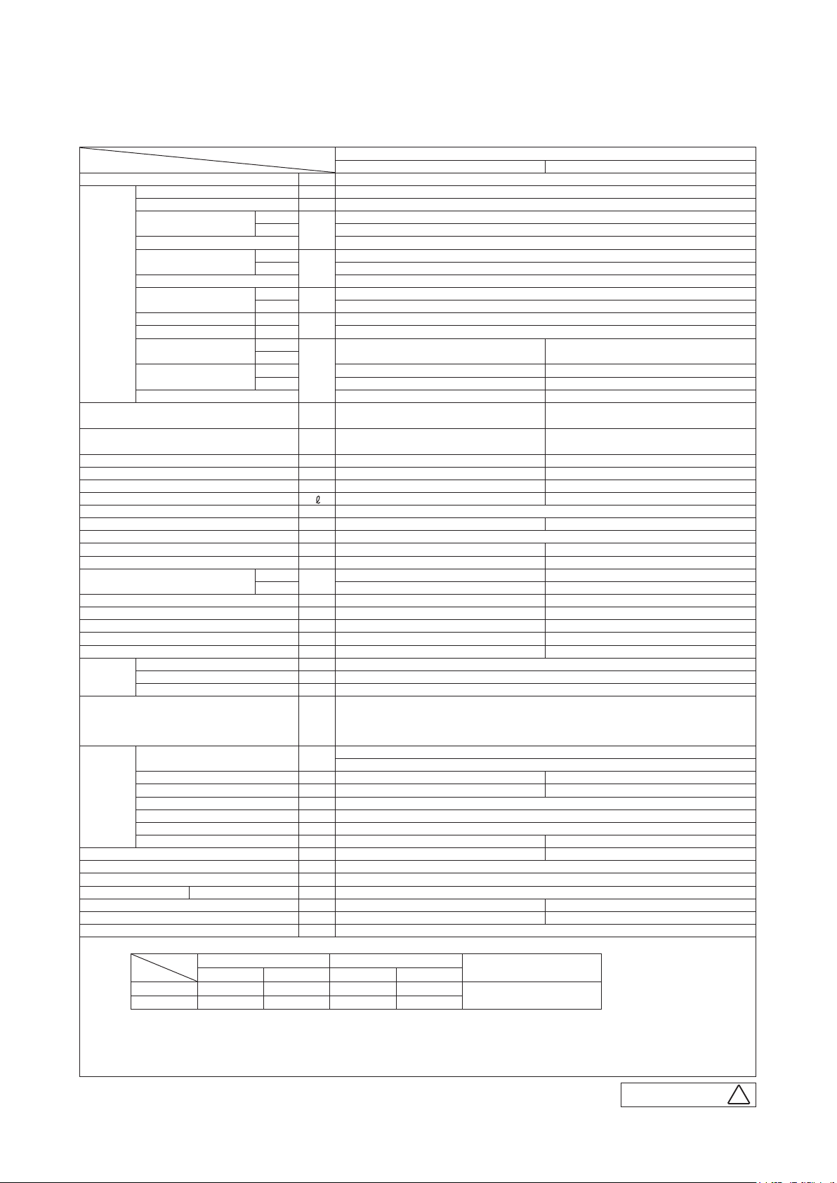
(1) Ceiling cassette-4way compact (FDTC)
Item
Power source 1 Phase 220-240V 50Hz / 220V 60Hz
Operation
data
Exterior dimensions (Height x Width x Depth) mm
Exterior appearance
( Munsell color )
Net weight kg Unit 15 Panel 3.5 45
Compressor type & Q'ty — RMT5113MCE2 ( Twin rotary type )×1
Compressor motor (Starting method) kW — Direct line start
Refrigerant oil (Amount, type)
Refrigerant (Type, amount, pre-charge length) kg R410A 1.5kg in outdoor unit (incl. the amount for the piping of : 15m)
Heat exchanger Louver fin & inner grooved tubing M shape fin & inner grooved tubing
Refrigerant control Capillary tubes + Electronic expansion valve
Fan type & Q'ty Turbo fan ×1 Propeller fan ×1
Fan motor (Starting method) W 33 < Direct line start > 34 < Direct line start >
Air flow
Available external static pressure Pa 0 —
Outside air intake Not possible —
Air filter, Quality / Quantity Pocket plastic net ×1(Washable) —
Shock & vibration absorber Rubber sleeve(for fan motor) Rubber sleeve(for compressor )
Electric heater W 0 —
Operation
control
Safety equipments
Installation
data
Drain pump, max lift height mm Built-in drain pump , 600 —
Recommended breaker size A —
L.R.A. (Locked rotor ampere) A 4.8
Interconnecting wires Size x Core number
IP number IPX0 IPX4
Standard accessories Mounting kit, Drain hose Drain elbow, Drain hole grommet
Option parts TC-OAS-E , TC-OAD-E
Nominal cooling capacity (range) kW 4.0 [ 1.1(Min.)- 4.7(Max.)]
Nominal heating capacity (range) kW 4.5 [ 0.6(Min.)- 5.4(Max.)]
Power consumption
Max power consumption 2.60
Running current
Inrush current, max current 5 , 12
Power factor
EER Cooling 3.85
COP Heating 4.09
Sound power level
Sound pressure level
Silent mode sound pressure level — Cooling : 42 / Heating : 43
Remote control (option) wired : RC-EX3 , RC-E5 , RCH-E3 wireless : RCN-TC-24W-E2
Room temperature control Thermostat by electronics
Operation display —
Refrigerant piping size ( O.D. ) mm
Connecting method Flare piping Flare piping
Attached length of piping m — —
Insulation for piping Necessary (both Liquid & Gas lines)
Refrigerant line (one way) length m Max.30m
Vertical height diff. between O.U. and I.U.
Drain hose Hose connectable VP20(O.D.26) Holes size φ20 × 5pcs
Notes (1) The data are measured at the following conditions.
Indoor air temperature Outdoor air temperature
Operation
(2) This air-conditioner is manufactured and tested in conformity with the ISO.
(3) Sound level indicates the value in an anechoic chamber. During operation these values are somewhat higher due to ambient conditions.
(4) Select the breaker size according to the own national standard.
(5) The operation data indicate when the air-conditioner is operated at 230V 50Hz or 220V 60Hz.
Item
Cooling 27˚C 19˚C 35˚C 24˚C
Heating 20˚C — 7˚C 6˚C
Cooling
Heating 1.10
Cooling
Heating 5.2 / 5.5
Cooling
Heating 92 / 91
Cooling
Heating
Cooling P-Hi : 47 Hi : 42 Me : 36 Lo : 30 50
Heating P-Hi : 47 Hi : 42 Me : 36 Lo : 32 49
Cooling
Heating P-Hi : 13.5 Hi : 11.5 Me : 9 Lo : 8 33
DB WB DB WB
Model
kW
A
%
dB(A)
m3/min
m Max.20m (Outdoor unit is higher) Max.20m (Outdoor unit is lower)
Indoor unit FDTC40VF Outdoor unit SRC40ZSX-S
60 63
Unit 248 × 570 × 570
Panel 35 × 700 × 700
Plaster white
( 6.8Y8.9/0.2 ) near equivalent
— 0.45 ( MA68 )
P-Hi : 13.5 Hi : 11.5 Me : 9 Lo : 7 36
Liquid line: I/Uφ6.35 (1/4") Pipeφ6.35(1/4") × 0.8 O/Uφ6.35 (1/4")
1.5mm
φ
Abnormal discharge temperature protection.
Gas line: φ12.7 (1/2") φ12.7(1/2") × 0.8 φ12.7 (1/2")
2
× 4 cores (Including earth cable) / Termainal block (Screw fixing type)
The pipe length is 7.5m.
FDTC40ZSXVF
1.04
4.9 / 5.1
92 / 93
640×800(+71)×290
Stucco white
( 4.2Y7.5/1.1 ) near equivalent
Overload protection for fan motor.
Frost protection thermostat.
Internal thermostat for fan motor.
Standards
ISO5151-T1
PJA003Z401
-
-
5
H

'17 • PAC-T-256
Item
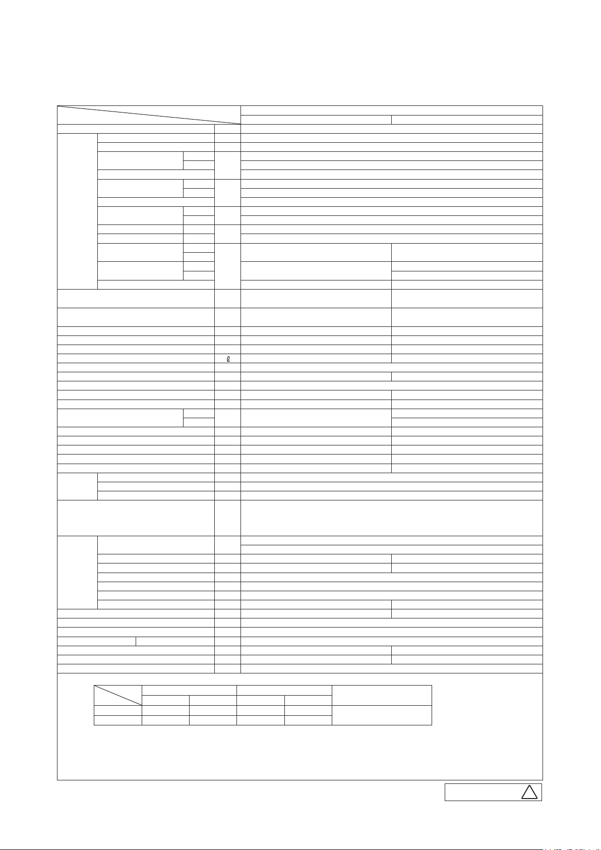
Power source 1 Phase 220-240V 50Hz / 220V 60Hz
Operation
data
Exterior dimensions (Height x Width x Depth) mm
Exterior appearance
( Munsell color )
Net weight kg Unit 15 Panel 3.5 45
Compressor type & Q'ty — RMT5113MCE2 ( Twin rotary type )×1
Compressor motor (Starting method) kW — Direct line start
Refrigerant oil (Amount, type)
Refrigerant (Type, amount, pre-charge length) kg R410A 1.5kg in outdoor unit (incl. the amount for the piping of : 15m)
Heat exchanger Louver fin & inner grooved tubing M shape fin & inner grooved tubing
Refrigerant control Capillary tubes + Electronic expansion valve
Fan type & Q'ty Turbo fan ×1 Propeller fan ×1
Fan motor (Starting method) W 33 < Direct line start > 34 < Direct line start >
Air flow
Available external static pressure Pa 0 —
Outside air intake Not possible —
Air filter, Quality / Quantity Pocket plastic net ×1(Washable) —
Shock & vibration absorber Rubber sleeve(for fan motor) Rubber sleeve(for compressor )
Electric heater W 0 —
Operation
control
Safety equipments
Installation
data
Drain pump, max lift height mm Built-in drain pump, 600 —
Recommended breaker size A —
L.R.A. (Locked rotor ampere) A 5.0
Interconnecting wires Size x Core number
IP number IPX0 IPX4
Standard accessories Mounting kit, Drain hose Drain elbow, Drain hole grommet
Option parts TC-OAS-E , TC-OAD-E
Nominal cooling capacity (range) kW 5.0 [ 1.1(Min.)- 5.6(Max.)]
Nominal heating capacity (range) kW 5.4 [ 0.6(Min.)- 6.3(Max.)]
Power consumption
Max power consumption 2.90
Running current
Inrush current, max current 5 , 15
Power factor
EER Cooling 3.21
COP Heating 3.72
Sound power level
Sound pressure level
Silent mode sound pressure level — Cooling : 42 / Heating : 43
Remote control (option) wired : RC-EX3 , RC-E5 , RCH-E3 wireless : RCN-TC-24W-E2
Room temperature control Thermostat by electronics
Operation display —
Refrigerant piping size ( O.D. ) mm
Connecting method Flare piping Flare piping
Attached length of piping m — —
Insulation for piping Necessary (both Liquid & Gas lines)
Refrigerant line (one way) length m Max.30m
Vertical height diff. between O.U. and I.U.
Drain hose Hose connectable VP20(O.D.26) Holes size φ20 × 5pcs
Notes (1) The data are measured at the following conditions.
Indoor air temperature Outdoor air temperature
Operation
(2) This air-conditioner is manufactured and tested in conformity with the ISO.
(3) Sound level indicates the value in an anechoic chamber. During operation these values are somewhat higher due to ambient conditions.
(4) Select the breaker size according to the own national standard.
(5) The operation data indicate when the air-conditioner is operated at 230V 50Hz or 220V 60Hz.
Item
Cooling 27˚C 19˚C 35˚C 24˚C
Heating 20˚C — 7˚C 6˚C
Cooling
Heating 1.45
Cooling
Heating 6.7 / 7.0
Cooling
Heating 94 / 94
Cooling
Heating
Cooling P-Hi : 47 Hi : 42 Me : 36 Lo : 30 50
Heating P-Hi : 47 Hi : 42 Me : 36 Lo : 32 49
Cooling
Heating P-Hi : 13.5 Hi : 11.5 Me : 9 Lo : 8 33
DB WB DB WB
Model
kW
A
%
dB(A)
m3/min
m Max.20m (Outdoor unit is higher) Max.20m (Outdoor unit is lower)
Indoor unit FDTC50VF Outdoor unit SRC50ZSX-S
60 63
Unit 248 × 570 × 570
Panel 35 × 700 × 700
Plaster white
( 6.8Y8.9/0.2 ) near equivalent
— 0.45 ( MA68 )
P-Hi : 13.5 Hi : 11.5 Me : 9 Lo : 7 40
Liquid line: I/Uφ6.35 (1/4") Pipeφ6.35(1/4") × 0.8 O/Uφ6.35 (1/4")
1.5mm
φ
Abnormal discharge temperature protection.
Gas line: φ12.7 (1/2") φ12.7(1/2") × 0.8 φ12.7 (1/2")
2
× 4 cores (Including earth cable) / Termainal block (Screw fixing type)
The pipe length is 7.5m.
FDTC50ZSXVF
1.56
7.2 / 7.5
94 / 95
640×800(+71)×290
Stucco white
( 4.2Y7.5/1.1 ) near equivalent
Overload protection for fan motor.
Frost protection thermostat.
Internal thermostat for fan motor.
Standards
ISO5151-T1
PJA003Z401
-
-
6
H

'17 • PAC-T-256
Item
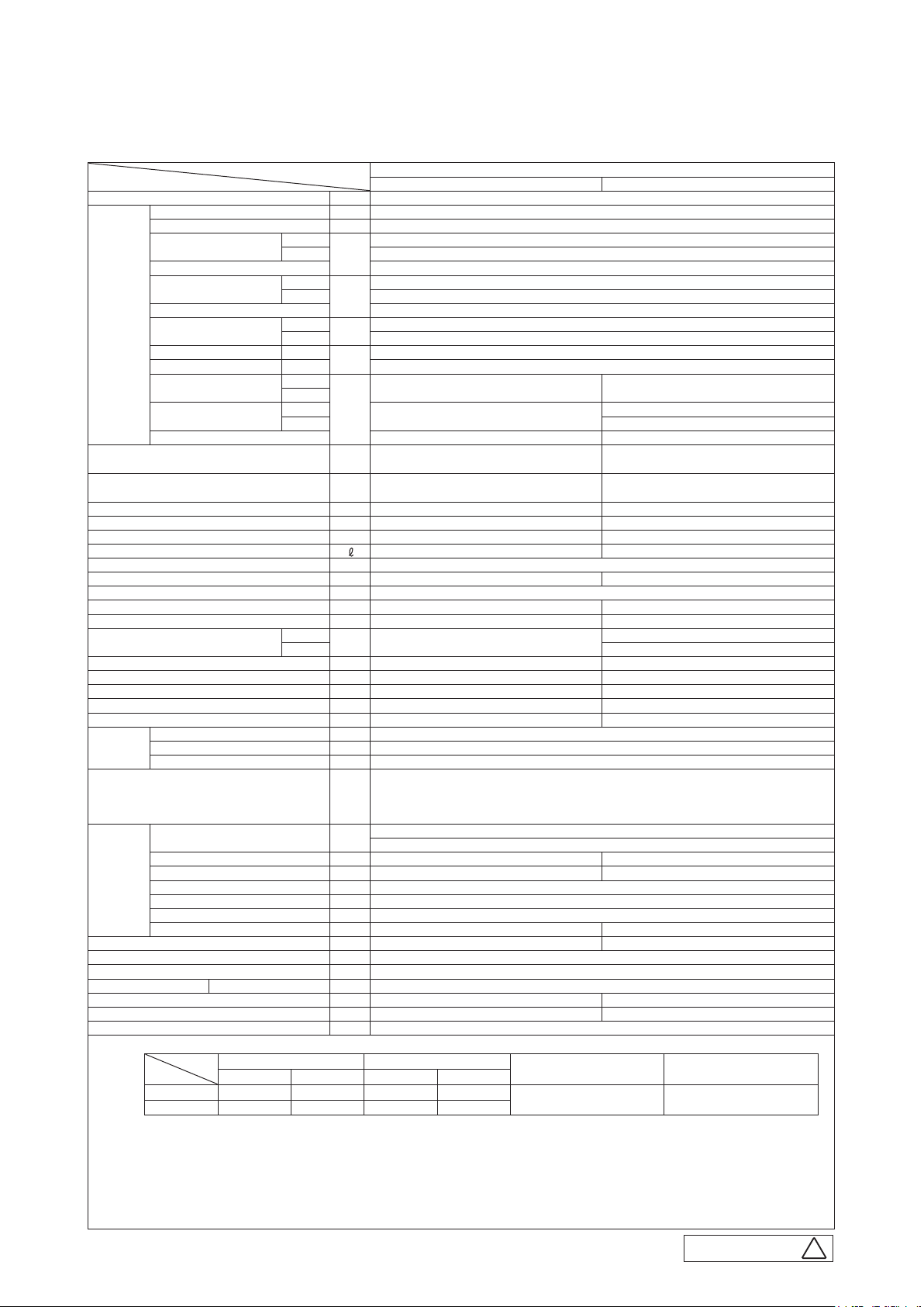
Power source 1 Phase 220-240V 50Hz / 220V 60Hz
Operation
data
Exterior dimensions (Height x Width x Depth) mm
Exterior appearance
( Munsell color )
Net weight kg Unit 15 Panel 3.5 45
Compressor type & Q'ty — RMT5113MCE2 ( Twin rotary type )×1
Compressor motor (Starting method) kW — Direct line start
Refrigerant oil (Amount, type)
Refrigerant (Type, amount, pre-charge length) kg R410A 1.5kg in outdoor unit (incl. the amount for the piping of : 15m)
Heat exchanger Louver fin & inner grooved tubing M shape fin & inner grooved tubing
Refrigerant control Capillary tubes + Electronic expansion valve
Fan type & Q'ty Turbo fan ×1 Propeller fan ×1
Fan motor (Starting method) W 33 < Direct line start > 34 < Direct line start >
Air flow
Available external static pressure Pa 0 —
Outside air intake Not possible —
Air filter, Quality / Quantity Pocket plastic net ×1(Washable) —
Shock & vibration absorber Rubber sleeve(for fan motor) Rubber sleeve(for compressor )
Electric heater W 0 —
Operation
control
Safety equipments
Installation
data
Drain pump, max lift height mm Built-in drain pump, 600 —
Recommended breaker size A —
L.R.A. (Locked rotor ampere) A 5.0
Interconnecting wires Size x Core number
IP number IPX0 IPX4
Standard accessories Mounting kit, Drain hose Drain elbow, Drain hole grommet
Option parts TC-OAS-E , TC-OAD-E
Nominal cooling capacity (range) kW 5.6 [ 1.1(Min.)- 6.3(Max.)]
Nominal heating capacity (range) kW 6.7 [ 0.6(Min.)- 6.7(Max.)]
Power consumption
Max power consumption 2.90
Running current
Inrush current, max current 5 , 15
Power factor
EER Cooling 2.81
COP Heating 3.24
Sound power level
Sound pressure level
Silent mode sound pressure level — Cooling : 42 / Heating : 43
Remote control (option) wired : RC-EX3 , RC-E5 , RCH-E3 wireless : RCN-TC-24W-E2
Room temperature control Thermostat by electronics
Operation display —
Refrigerant piping size ( O.D. ) mm
Connecting method Flare piping Flare piping
Attached length of piping m — —
Insulation for piping Necessary (both Liquid & Gas lines)
Refrigerant line (one way) length m Max.30m
Vertical height diff. between O.U. and I.U.
Drain hose Hose connectable VP20(O.D.26) Holes size φ20 × 5pcs
Notes (1) The data are measured at the following conditions.
Indoor air temperature Outdoor air temperature
Operation
(2) This air-conditioner is manufactured and tested in conformity with the ISO.
(3) Sound level indicates the value in an anechoic chamber. During operation these values are somewhat higher due to ambient conditions.
(4) Select the breaker size according to the own national standard.
(5) The operation data indicate when the air-conditioner is operated at 230V 50Hz or 220V 60Hz.
Item
Cooling 27˚C 19˚C 35˚C 24˚C
Heating 20˚C — 7˚C 6˚C
Cooling
Heating 2.07
Cooling
Heating 9.6 / 10.1
Cooling
Heating 94 / 93
Cooling
Heating 64
Cooling P-Hi : 47 Hi : 46 Me : 39 Lo : 30
Heating P-Hi : 47 Hi : 46 Me : 39 Lo : 32
Cooling
Heating P-Hi : 13.5 Hi : 13.5 Me : 10 Lo : 8 39
DB WB DB WB
Model
kW
A
%
dB(A)
m3/min
m Max.20m (Outdoor unit is higher) Max.20m (Outdoor unit is lower)
Indoor unit FDTC60VF Outdoor unit SRC60ZSX-S
60
Unit 248 × 570 × 570
Panel 35 × 700 × 700
Plaster white
( 6.8Y8.9/0.2 ) near equivalent
— 0.45 ( MA68 )
P-Hi : 13.5 Hi : 13.5 Me : 10 Lo : 7 41.5
Liquid line: I/Uφ6.35 (1/4") Pipeφ6.35(1/4") × 0.8 O/Uφ6.35 (1/4")
1.5mm
φ
Abnormal discharge temperature protection.
Gas line: φ12.7 (1/2") φ12.7(1/2") × 0.8 φ12.7 (1/2")
2
× 4 cores (Including earth cable) / Termainal block (Screw fixing type)
The pipe length is 7.5m.
FDTC60ZSXVF
1.99
9.1 / 9.5
95 / 95
65
52
640×800(+71)×290
Stucco white
( 4.2Y7.5/1.1 ) near equivalent
Overload protection for fan motor.
Frost protection thermostat.
Internal thermostat for fan motor.
Standards
ISO5151-T1
PJA003Z401
-
-
7
H

'17 • PAC-T-256
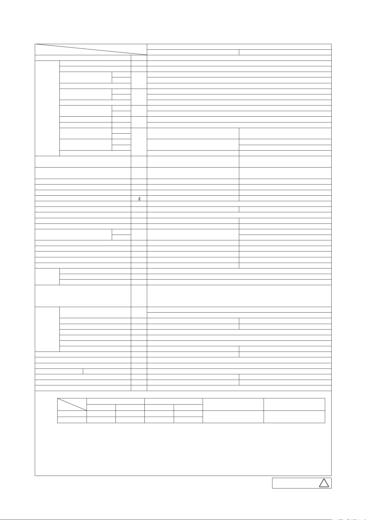
(2) Ceiling suspended type (FDE)
Item
Power source 1 Phase 220-240V 50Hz / 220V 60Hz
Operation
data
Exterior dimensions (Height x Width x Depth) mm 210 × 1,070 × 690 640×800(+71)×290
Exterior appearance
( Munsell color )
Net weight kg 28 45
Compressor type & Q'ty — RMT5113MCE2 ( Twin rotary type )×1
Compressor motor (Starting method) kW — Direct line start
Refrigerant oil (Amount, type)
Refrigerant (Type, amount, pre-charge length) kg R410A 1.5kg in outdoor unit (incl. the amount for the piping of : 15m)
Heat exchanger Louver fin & inner grooved tubing M shape fin & inner grooved tubing
Refrigerant control Capillary tubes + Electronic expansion valve
Fan type & Q'ty Centrifugal fan ×2 Propeller fan ×1
Fan motor (Starting method) W 30 < Direct line start > 34 < Direct line start >
Air flow
Available external static pressure Pa 0 —
Outside air intake Not possible —
Air filter, Quality / Quantity Pocket plastic net ×2(Washable) —
Shock & vibration absorber Rubber sleeve(for fan motor) Rubber sleeve(for compressor )
Electric heater W 0 —
Operation
control
Safety equipments
Installation
data
Drain pump, max lift height mm — —
Recommended breaker size A —
L.R.A. (Locked rotor ampere) A 4.8
Interconnecting wires Size x Core number 1.5mm
IP number IPX0 IPX4
Standard accessories Mounting kit, Drain hose Drain elbow, Drain hole grommet
Option parts —
Nominal cooling capacity (range) kW 4.0 [ 1.1(Min.)-4.7(Max.)]
Nominal heating capacity (range) kW 4.5 [ 0.6(Min.)-5.4(Max.)]
Power consumption
Max power consumption 2.60
Running current
Inrush current, max current 5 , 12
Power factor
EER Cooling 3.92
COP Heating 4.09
Sound power level
Sound pressure level
Silent mode sound pressure level — Cooling : 42 / Heating : 43
Remote control (option) wired : RC-EX3 , RC-E5 , RCH-E3 wireless : RCN-E-E2
Room temperature control Thermostat by electronics
Operation display —
Refrigerant piping size ( O.D. ) mm
Connecting method Flare piping Flare piping
Attached length of piping m — —
Insulation for piping Necessary (both Liquid & Gas lines)
Refrigerant line (one way) length m Max.30m
Vertical height diff. between O.U. and I.U.
Drain hose Hose connectable with VP20(O.D.26) Holes size φ20 x 5pcs
Notes (1) The data are measured at the following conditions.
Indoor air temperature Outdoor air temperature
Operation
(2) This air-conditioner is manufactured and tested in conformity with the ISO.
(3) Sound level indicates the value in an anechoic chamber. During operation these values are somewhat
(4) Select the breaker size according to the own national standard.
(5) The operation data indicate when the air-conditioner is operated at 230V 50Hz or 220V 60Hz.
Item
Cooling 27˚C 19˚C 35˚C 24˚C
Heating 20˚C — 7˚C 6˚C
higher due to ambient conditions.
Cooling
Heating 1.10
Cooling
Heating 5.1 / 5.4
Cooling
Heating 94 / 93
Cooling
Heating
Cooling
Heating 49
Cooling
Heating 33
DB WB DB WB
Model
kW
A
%
dB(A)
m3/min
m Max.20m (Outdoor unit is higher) Max.20m (Outdoor unit is lower)
Indoor unit FDE40VG Outdoor unit SRC40ZSX-S
60 63
P-Hi : 46 Hi : 38 Me : 36 Lo : 31
Plaster white
( 6.8Y8.9/0.2 ) near equivalent
— 0.45 ( MA68 )
P-Hi : 13 Hi : 10 Me : 9 Lo : 7
Liquid line: I/Uφ6.35 (1/4") Pipeφ6.35(1/4")x0.8 O/Uφ6.35 (1/4")
Abnormal discharge temperature protection.
Gas line: φ12.7 (1/2") φ12.7(1/2")x0.8 φ12.7 (1/2")
2
×4 cores (Including earth cable) / Termainal block (Screw fixing type)
The pipe length is 7.5m.
FDE40ZSXVG
1.02
4.8 / 5.0
92 / 93
50
Stucco white
( 4.2Y7.5/1.1 ) near equivalent
36
Internal thermostat for fan motor
Frost protection thermostat
Internal thermostat for fan motor
Standards
ISO5151-T1
PFA004Z024
-
-
8
H
'17 • PAC-T-256
Item
Power source 1 Phase 220-240V 50Hz / 220V 60Hz
Operation
data
Exterior dimensions (Height x Width x Depth) mm 210 × 1,070 × 690 640×800(+71)×290
Exterior appearance
( Munsell color )
Net weight kg 28 45
Compressor type & Q'ty — RMT5113MCE2 ( Twin rotary type )×1
Compressor motor (Starting method) kW — Direct line start
Refrigerant oil (Amount, type)
Refrigerant (Type, amount, pre-charge length) kg R410A 1.5kg in outdoor unit (incl. the amount for the piping of : 15m)
Heat exchanger Louver fin & inner grooved tubing M shape fin & inner grooved tubing
Refrigerant control Capillary tubes + Electronic expansion valve
Fan type & Q'ty Centrifugal fan ×2 Propeller fan ×1
Fan motor (Starting method) W 30 < Direct line start > 34 < Direct line start >
Air flow
Available external static pressure Pa 0 —
Outside air intake Not possible —
Air filter, Quality / Quantity Pocket plastic net ×2(Washable) —
Shock & vibration absorber Rubber sleeve(for fan motor) Rubber sleeve(for compressor )
Electric heater W 0 —
Operation
control
Safety equipments
Installation
data
Drain pump, max lift height mm — —
Recommended breaker size A —
L.R.A. (Locked rotor ampere) A 5.0
Interconnecting wires Size x Core number 1.5mm
IP number IPX0 IPX4
Standard accessories Mounting kit, Drain hose Drain elbow, Drain hole grommet
Option parts —
Nominal cooling capacity (range) kW 5.0 [ 1.1(Min.)-5.6(Max.)]
Nominal heating capacity (range) kW 5.4 [ 0.6(Min.)-6.3(Max.)]
Power consumption
Max power consumption 2.90
Running current
Inrush current, max current 5 , 15
Power factor
EER Cooling 3.29
COP Heating 3.70
Sound power level
Sound pressure level
Silent mode sound pressure level — Cooling : 42 / Heating : 43
Remote control (option) wired : RC-EX3 , RC-E5 , RCH-E3 wireless : RCN-E-E2
Room temperature control Thermostat by electronics
Operation display —
Refrigerant piping size ( O.D. ) mm
Connecting method Flare piping Flare piping
Attached length of piping m — —
Insulation for piping Necessary (both Liquid & Gas lines)
Refrigerant line (one way) length m Max.30m
Vertical height diff. between O.U. and I.U.
Drain hose Hose connectable with VP20(O.D.26) Holes size φ20 x 5pcs
Notes (1) The data are measured at the following conditions.
Indoor air temperature Outdoor air temperature
Operation
(2) This air-conditioner is manufactured and tested in conformity with the ISO.
(3) Sound level indicates the value in an anechoic chamber. During operation these values are somewhat
(4) Select the breaker size according to the own national standard.
(5) The operation data indicate when the air-conditioner is operated at 230V 50Hz or 220V 60Hz.
Item
Cooling 27˚C 19˚C 35˚C 24˚C
Heating 20˚C — 7˚C 6˚C
higher due to ambient conditions.
Cooling
Heating 1.46
Cooling
Heating 7.0 / 7.3
Cooling
Heating 91
Cooling
Heating
Cooling
Heating 49
Cooling
Heating 33
DB WB DB WB
Model
kW
A
%
dB(A)
m3/min
m Max.20m (Outdoor unit is higher) Max.20m (Outdoor unit is lower)
Indoor unit FDE50VG Outdoor unit SRC50ZSX-S
60 63
P-Hi : 46 Hi : 38 Me : 36 Lo : 31
Plaster white
( 6.8Y8.9/0.2 )near equivalent
— 0.45 ( MA68 )
P-Hi : 13 Hi : 10 Me : 9 Lo : 7
Liquid line: I/Uφ6.35 (1/4") Pipeφ6.35(1/4")x0.8 O/Uφ6.35 (1/4")
Abnormal discharge temperature protection.
Gas line: φ12.7 (1/2") φ12.7(1/2")x0.8 φ12.7 (1/2")
2
×4 cores (Including earth cable) / Termainal block (Screw fixing type)
The pipe length is 7.5m.
FDE50ZSXVG
1.52
7.0 / 7.4
94 / 93
50
Stucco white
( 4.2Y7.5/1.1 )near equivalent
40
Internal thermostat for fan motor
Frost protection thermostat
Internal thermostat for fan motor
Standards
ISO5151-T1
PFA004Z024
-
-
9
H

'17 • PAC-T-256
Item
Power source 1 Phase 220-240V 50Hz / 220V 60Hz
Operation
data
Exterior dimensions (Height x Width x Depth) mm 210 × 1,320 × 690 640×800(+71)×290
Exterior appearance
( Munsell color )
Net weight kg 33 45
Compressor type & Q'ty — RMT5113MCE2 ( Twin rotary type )×1
Compressor motor (Starting method) kW — Direct line start
Refrigerant oil (Amount, type)
Refrigerant (Type, amount, pre-charge length) kg R410A 1.5kg in outdoor unit (incl. the amount for the piping of : 15m)
Heat exchanger Louver fin & inner grooved tubing M shape fin & inner grooved tubing
Refrigerant control Capillary tubes + Electronic expansion valve
Fan type & Q'ty Centrifugal fan ×4 Propeller fan ×1
Fan motor (Starting method) W 50 < Direct line start > 34 < Direct line start >
Air flow
Available external static pressure Pa 0 —
Outside air intake Not possible —
Air filter, Quality / Quantity Pocket plastic net ×2(Washable) —
Shock & vibration absorber Rubber sleeve(for fan motor) Rubber sleeve(for compressor )
Electric heater W 0 —
Operation
control
Safety equipments
Installation
data
Drain pump, max lift height mm — —
Recommended breaker size A —
L.R.A. (Locked rotor ampere) A 5.0
Interconnecting wires Size x Core number 1.5mm
IP number IPX0 IPX4
Standard accessories Mounting kit, Drain hose Drain elbow, Drain hole grommet
Option parts —
Nominal cooling capacity (range) kW 5.6 [ 1.1(Min.)-6.3(Max.)]
Nominal heating capacity (range) kW 6.7 [ 0.6(Min.)-7.1(Max.)]
Power consumption
Max power consumption 2.90
Running current
Inrush current, max current 5 , 15
Power factor
EER Cooling 3.20
COP Heating 3.60
Sound power level
Sound pressure level
Silent mode sound pressure level — Cooling : 42 / Heating : 43
Remote control (option) wired : RC-EX3 , RC-E5 , RCH-E3 wireless : RCN-E-E2
Room temperature control Thermostat by electronics
Operation display —
Refrigerant piping size ( O.D. ) mm
Connecting method Flare piping Flare piping
Attached length of piping m — —
Insulation for piping Necessary (both Liquid & Gas lines)
Refrigerant line (one way) length m Max.30m
Vertical height diff. between O.U. and I.U.
Drain hose Hose connectable with VP20(O.D.26) Holes size φ20 x 5pcs
Notes (1) The data are measured at the following conditions.
Indoor air temperature Outdoor air temperature
Operation
(2) This air-conditioner is manufactured and tested in conformity with the ISO.
(3) Sound level indicates the value in an anechoic chamber. During operation these values are somewhat
(4) Select the breaker size according to the own national standard.
(5) The operation data indicate when the air-conditioner is operated at 230V 50Hz or 220V 60Hz.
Item
Cooling 27˚C 19˚C 35˚C 24˚C
Heating 20˚C — 7˚C 6˚C
higher due to ambient conditions.
Cooling
Heating 1.86
Cooling
Heating 8.7 / 9.1
Cooling
Heating 93
Cooling
Heating 64
Cooling
Heating
Cooling
Heating 39
DB WB DB WB
Model
kW
A
%
dB(A)
m3/min
m Max.20m (Outdoor unit is higher) Max.20m (Outdoor unit is lower)
Indoor unit FDE60VG Outdoor unit SRC60ZSX-S
60
P-Hi : 47 Hi : 41 Me : 37 Lo : 32 52
Plaster white
( 6.8Y8.9/0.2 )near equivalent
— 0.45 ( MA68 )
P-Hi : 20 Hi : 16 Me : 13 Lo : 10
Liquid line: I/Uφ6.35 (1/4") Pipeφ6.35(1/4")x0.8 O/Uφ6.35 (1/4")
Abnormal discharge temperature protection.
Gas line: φ12.7 (1/2") φ12.7(1/2")x0.8 φ12.7 (1/2")
2
×4 cores (Including earth cable) / Termainal block (Screw fixing type)
The pipe length is 7.5m.
FDE60ZSXVG
1.75
8.0 / 8.4
95
65
Stucco white
( 4.2Y7.5/1.1 )near equivalent
41.5
Internal thermostat for fan motor
Frost protection thermostat
Internal thermostat for fan motor
Standards
ISO5151-T1
-
10
PFA004Z024
H
-
'17 • PAC-T-256
(3) Duct connected-Low / Middle static pressure tpye (FDUM)
Item
Power source 1 Phase 220-240V 50Hz / 220V 60Hz
Operation
data
Exterior dimensions (Height x Width x Depth) mm 280 × 750 × 635 640×800(+71)×290
Exterior appearance
( Munsell color )
Net weight kg 29 45
Compressor type & Q'ty — RMT5113MCE2 ( Twin rotary type )×1
Compressor motor (Starting method) kW — Direct line start
Refrigerant oil (Amount, type)
Refrigerant (Type, amount, pre-charge length) kg R410A 1.5kg in outdoor unit (incl. the amount for the piping of : 15m)
Heat exchanger Louver fin & inner grooved tubing M shape fin & inner grooved tubing
Refrigerant control Capillary tubes + Electronic expansion valve
Fan type & Q'ty Centrifugal fan ×1 Propeller fan ×1
Fan motor (Starting method) W 100 < Direct line start > 34 < Direct line start >
Air flow
Available external static pressure Pa Standard : 35 Max : 100 —
Outside air intake Possible —
Air filter, Quality / Quantity Procure locally —
Shock & vibration absorber Rubber sleeve(for fan motor) Rubber sleeve(for compressor )
Electric heater W — —
Operation
control
Safety equipments
Installation
data
Drain pump, max lift height mm Built-in drain pump , 600 —
Recommended breaker size A —
L.R.A. (Locked rotor ampere) A 4.8
Interconnecting wires Size x Core number 1.5mm
IP number IPX0 IPX4
Standard accessories Mounting kit, Drain hose Drain elbow, Drain hole grommet
Option parts UM-FL1EF
Nominal cooling capacity (range) kW 4.0 [ 1.1(Min.)- 4.7(Max.)]
Nominal heating capacity (range) kW 4.5 [ 0.6(Min.)- 5.4(Max.)]
Power consumption
Max power consumption 2.60
Running current
Inrush current, max current 5 , 12
Power factor
EER Cooling 4.20
COP Heating 4.21
Sound power level
Sound pressure level
Silent mode sound pressure level — Cooling : 42 / Heating : 43
Remote control (option) wired : RC-EX3 , RC-E5 , RCH-E3 wireless : RCN-KIT4-E2
Room temperature control Thermostat by electronics
Operation display —
Refrigerant piping size ( O.D. ) mm
Connecting method Flare piping Flare piping
Attached length of piping m — —
Insulation for piping Necessary (both Liquid & Gas lines)
Refrigerant line (one way) length m Max.30m
Vertical height diff. between O.U. and I.U.
Drain hose Hose Connectable with VP25(O.D.32) Holes size φ20 x 5pcs
Notes (1) The data are measured at the following conditions.
Indoor air temperature Outdoor air temperature
Operation
(2) This air-conditioner is manufactured and tested in conformity with the ISO.
(3) Sound level indicates the value in an anechoic chamber. During operation these values are somewhat
higher due to ambient conditions.
(4) Select the breaker size according to the own national standard.
(5) The operation data indicate when the air-conditioner is operated at 230V 50Hz or 220V 60Hz.
(6) Static pressure of optional air filter "UM-FL1EF" is 5Pa initially.
(7) The external static pressure setting can be changed to 10-100Pa. (For RC-EX3 and RC-E5 only)
Item
Cooling 27˚C 19˚C 35˚C 24˚C
Heating 20˚C — 7˚C 6˚C
Cooling
Heating 1.07
Cooling
Heating 4.9 / 5.1
Cooling
Heating 95
Cooling
Heating
Cooling
Heating 49
Cooling
Heating 33
DB WB DB WB
Model
kW
A
%
dB(A)
m3/min
m Max.20m (Outdoor unit is higher) Max.20m (Outdoor unit is lower)
Indoor unit FDUM40VF Outdoor unit SRC40ZSX-S
60 63
P-Hi : 37 Hi : 32 Me : 29 Lo : 26
—
— 0.45 ( MA68 )
P-Hi : 13 Hi : 10 Me : 9 Lo : 8
Liquid line: I.U.φ6.35 (1/4") Pipeφ6.35(1/4")x0.8 O.U.φ6.35 (1/4")
Abnormal discharge temperature protection.
Gas line: φ12.7 (1/2") φ12.7 (1/2")x0.8 φ12.7 (1/2")
2
x 4 cores (Including earth cable) / Termainal block (Screw fixing type)
FDUM40ZSXVF
0.952
4.4 / 4.6
94
( 4.2Y7.5/1.1 ) near equivalent
Overload protection for fan motor.
Frost protection thermostat.
Internal thermostat for fan motor.
External static pressure
of indoor unit
35Pa ISO5151-T1
50
Stucco white
36
The pipe length is 7.5m.
Standards
-
11
-
PJG000Z159
M
'17 • PAC-T-256
Item
Power source 1 Phase 220-240V 50Hz / 220V 60Hz
Operation
data
Exterior dimensions (Height x Width x Depth) mm 280 × 750 × 635 640×800(+71)×290
Exterior appearance
( Munsell color )
Net weight kg 29 45
Compressor type & Q'ty — RMT5113MCE2 ( Twin rotary type )×1
Compressor motor (Starting method) kW — Direct line start
Refrigerant oil (Amount, type)
Refrigerant (Type, amount, pre-charge length) kg R410A 1.5kg in outdoor unit (incl. the amount for the piping of : 15m)
Heat exchanger Louver fin & inner grooved tubing M shape fin & inner grooved tubing
Refrigerant control Capillary tubes + Electronic expansion valve
Fan type & Q'ty Centrifugal fan ×1 Propeller fan ×1
Fan motor (Starting method) W 100 < Direct line start > 34 < Direct line start >
Air flow
Available external static pressure Pa Standard : 35 Max : 100 —
Outside air intake Possible —
Air filter, Quality / Quantity Procure locally —
Shock & vibration absorber Rubber sleeve(for fan motor) Rubber sleeve(for compressor )
Electric heater W — —
Operation
control
Safety equipments
Installation
data
Drain pump, max lift height mm Built-in drain pump , 600 —
Recommended breaker size A —
L.R.A. (Locked rotor ampere) A 5.0
Interconnecting wires Size x Core number 1.5mm
IP number IPX0 IPX4
Standard accessories Mounting kit, Drain hose Drain elbow, Drain hole grommet
Option parts UM-FL1EF
Nominal cooling capacity (range) kW 5.0 [ 1.1(Min.)- 5.6(Max.)]
Nominal heating capacity (range) kW 5.4 [ 0.6(Min.)- 6.3(Max.)]
Power consumption
Max power consumption 2.90
Running current
Inrush current, max current 5 , 15
Power factor
EER Cooling 3.62
COP Heating 3.72
Sound power level
Sound pressure level
Silent mode sound pressure level — Cooling : 42 / Heating : 43
Remote control (option) wired : RC-EX3 , RC-E5 , RCH-E3 wireless : RCN-KIT4-E2
Room temperature control Thermostat by electronics
Operation display —
Refrigerant piping size ( O.D. ) mm
Connecting method Flare piping Flare piping
Attached length of piping m — —
Insulation for piping Necessary (both Liquid & Gas lines)
Refrigerant line (one way) length m Max.30m
Vertical height diff. between O.U. and I.U.
Drain hose Hose Connectable with VP25(O.D.32) Holes size φ20 x 5pcs
Notes (1) The data are measured at the following conditions.
Indoor air temperature Outdoor air temperature
Operation
(2) This air-conditioner is manufactured and tested in conformity with the ISO.
(3) Sound level indicates the value in an anechoic chamber. During operation these values are somewhat
higher due to ambient conditions.
(4) Select the breaker size according to the own national standard.
(5) The operation data indicate when the air-conditioner is operated at 230V 50Hz or 220V 60Hz.
(6) Static pressure of optional air filter "UM-FL1EF" is 5Pa initially.
(7) The external static pressure setting can be changed to 10-100Pa. (For RC-EX3 and RC-E5 only)
Item
Cooling 27˚C 19˚C 35˚C 24˚C
Heating 20˚C — 7˚C 6˚C
Cooling
Heating 1.45
Cooling
Heating 6.6 / 6.9
Cooling
Heating 96
Cooling
Heating
Cooling
Heating 49
Cooling
Heating 33
DB WB DB WB
Model
kW
A
%
dB(A)
m3/min
m Max.20m (Outdoor unit is higher) Max.20m (Outdoor unit is lower)
Indoor unit FDUM50VF Outdoor unit SRC50ZSX-S
60 63
P-Hi : 37 Hi : 32 Me : 29 Lo : 26
—
— 0.45 ( MA68 )
P-Hi : 13 Hi : 10 Me : 9 Lo : 8
Liquid line: I.U.φ6.35 (1/4") Pipeφ6.35(1/4")x0.8 O.U.φ6.35 (1/4")
Abnormal discharge temperature protection.
Gas line: φ12.7 (1/2") φ12.7 (1/2")x0.8 φ12.7 (1/2")
2
x 4 cores (Including earth cable) / Termainal block (Screw fixing type)
FDUM50ZSXVF
1.38
6.3 / 6.6
95
( 4.2Y7.5/1.1 ) near equivalent
Overload protection for fan motor.
Frost protection thermostat.
Internal thermostat for fan motor.
External static pressure
of indoor unit
35Pa ISO5151-T1
50
Stucco white
40
The pipe length is 7.5m.
Standards
-
12
PJG000Z159
M
-
'17 • PAC-T-256
Item
Power source 1 Phase 220-240V 50Hz / 220V 60Hz
Operation
data
Exterior dimensions (Height x Width x Depth) mm 280 × 950 × 635 640×800(+71)×290
Exterior appearance
( Munsell color )
Net weight kg 34 45
Compressor type & Q'ty — RMT5113MCE2 ( Twin rotary type )×1
Compressor motor (Starting method) kW — Direct line start
Refrigerant oil (Amount, type)
Refrigerant (Type, amount, pre-charge length) kg R410A 1.5kg in outdoor unit (incl. the amount for the piping of : 15m)
Heat exchanger Louver fin & inner grooved tubing M shape fin & inner grooved tubing
Refrigerant control Capillary tubes + Electronic expansion valve
Fan type & Q'ty Centrifugal fan ×2 Propeller fan ×1
Fan motor (Starting method) W 130 < Direct line start > 34 < Direct line start >
Air flow
Available external static pressure Pa Standard : 35 Max : 100 —
Outside air intake Possible —
Air filter, Quality / Quantity Procure locally —
Shock & vibration absorber Rubber sleeve(for fan motor) Rubber sleeve(for compressor )
Electric heater W — —
Operation
control
Safety equipments
Installation
data
Drain pump, max lift height mm Built-in drain pump , 600 —
Recommended breaker size A —
L.R.A. (Locked rotor ampere) A 5.0
Interconnecting wires Size x Core number 1.5mm
IP number IPX0 IPX4
Standard accessories Mounting kit, Drain hose Drain elbow, Drain hole grommet
Option parts UM-FL2EF
Nominal cooling capacity (range) kW 5.6 [ 1.1(Min.)- 6.3(Max.)]
Nominal heating capacity (range) kW 6.7 [ 0.6(Min.)- 7.1(Max.)]
Power consumption
Max power consumption 2.90
Running current
Inrush current, max current 5 , 15
Power factor
EER Cooling 3.64
COP Heating 3.83
Sound power level
Sound pressure level
Silent mode sound pressure level — Cooling : 42 / Heating : 43
Remote control (option) wired : RC-EX3 , RC-E5 , RCH-E3 wireless : RCN-KIT4-E2
Room temperature control Thermostat by electronics
Operation display —
Refrigerant piping size ( O.D. ) mm
Connecting method Flare piping Flare piping
Attached length of piping m — —
Insulation for piping Necessary (both Liquid & Gas lines)
Refrigerant line (one way) length m Max.30m
Vertical height diff. between O.U. and I.U.
Drain hose Hose Connectable with VP25(O.D.32) Holes size φ20 x 5pcs
Notes (1) The data are measured at the following conditions.
Indoor air temperature Outdoor air temperature
Operation
(2) This air-conditioner is manufactured and tested in conformity with the ISO.
(3) Sound level indicates the value in an anechoic chamber. During operation these values are somewhat
higher due to ambient conditions.
(4) Select the breaker size according to the own national standard.
(5) The operation data indicate when the air-conditioner is operated at 230V 50Hz or 220V 60Hz.
(6) Static pressure of optional air filter "UM-FL1EF" is 5Pa initially.
(7) The external static pressure setting can be changed to 10-100Pa. (For RC-EX3 and RC-E5 only)
Item
Cooling 27˚C 19˚C 35˚C 24˚C
Heating 20˚C — 7˚C 6˚C
Cooling
Heating 1.75
Cooling
Heating 7.8 / 8.2
Cooling
Heating 98 / 97
Cooling
Heating 64
Cooling
Heating
Cooling
Heating 39
DB WB DB WB
Model
kW
A
%
dB(A)
m3/min
m Max.20m (Outdoor unit is higher) Max.20m (Outdoor unit is lower)
Indoor unit FDUM60VF Outdoor unit SRC60ZSX-S
60
P-Hi : 36 Hi : 31 Me : 28 Lo : 25 52
—
— 0.45 ( MA68 )
P-Hi : 20 Hi : 15 Me : 13 Lo : 10
Liquid line: I.U.φ6.35 (1/4") Pipeφ6.35(1/4")x0.8 O.U.φ6.35 (1/4")
Abnormal discharge temperature protection.
Gas line: φ12.7 (1/2") φ12.7 (1/2")x0.8 φ12.7 (1/2")
2
x 4 cores (Including earth cable) / Termainal block (Screw fixing type)
FDUM60ZSXVF
1.54
6.8 / 7.1
98 / 99
( 4.2Y7.5/1.1 ) near equivalent
Overload protection for fan motor.
Frost protection thermostat.
Internal thermostat for fan motor.
External static pressure
of indoor unit
35Pa ISO5151-T1
65
Stucco white
41.5
The pipe length is 7.5m.
Standards
-
13
PJG000Z159
M
-
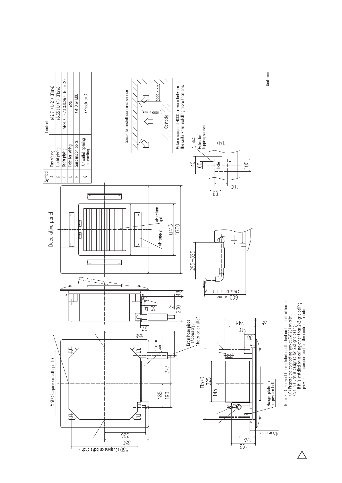
2. EXTERIOR DIMENSIONS
(1) Indoor units
(a) Ceiling cassette-4way compact type (FDTC)
Models FDTC40VF, 50VF, 60VF
'17 • PAC-T-256
G
G
G
G
-
D
14
F
C
B
A
-
PJA003Z338
D
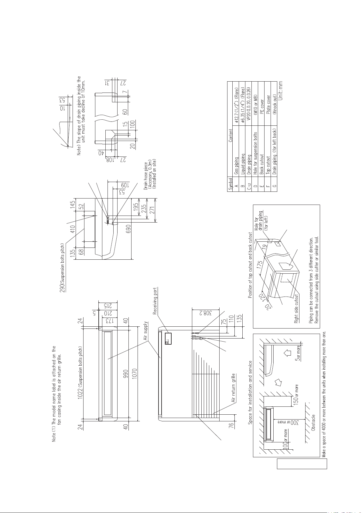
(b) Ceiling suspended type (FDE)
Models FDE40VG, 50VG
2
,C
1
C
A
B
2
,C
1
C
'17 • PAC-T-256
D
B
1
C
A
G
E
F
-
15
2
C
PFA004Z025
-
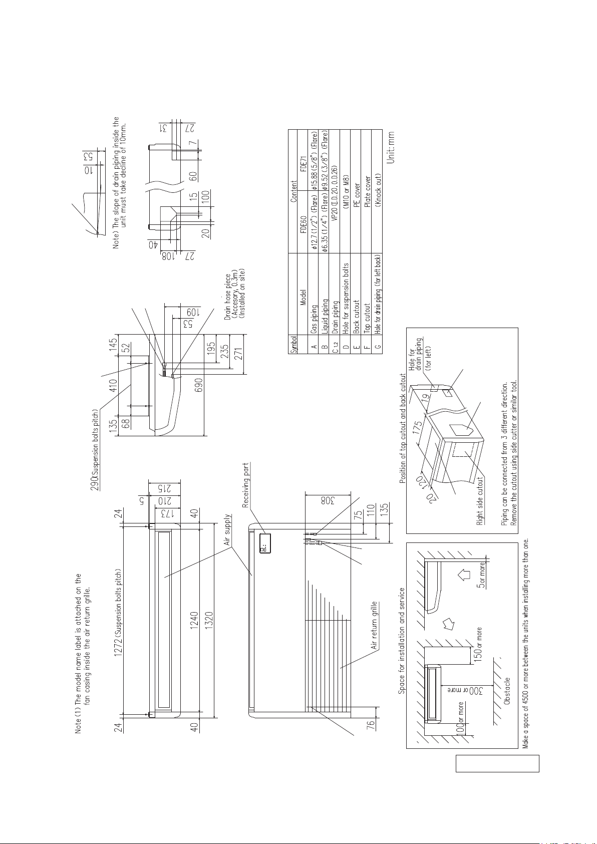
Model FDE60VG
C
,C
2
1
'17 • PAC-T-256
D
B
A
2
,C
1
C
B
1
C
A
G
E
F
-
16
2
C
PFA004Z026
-
M
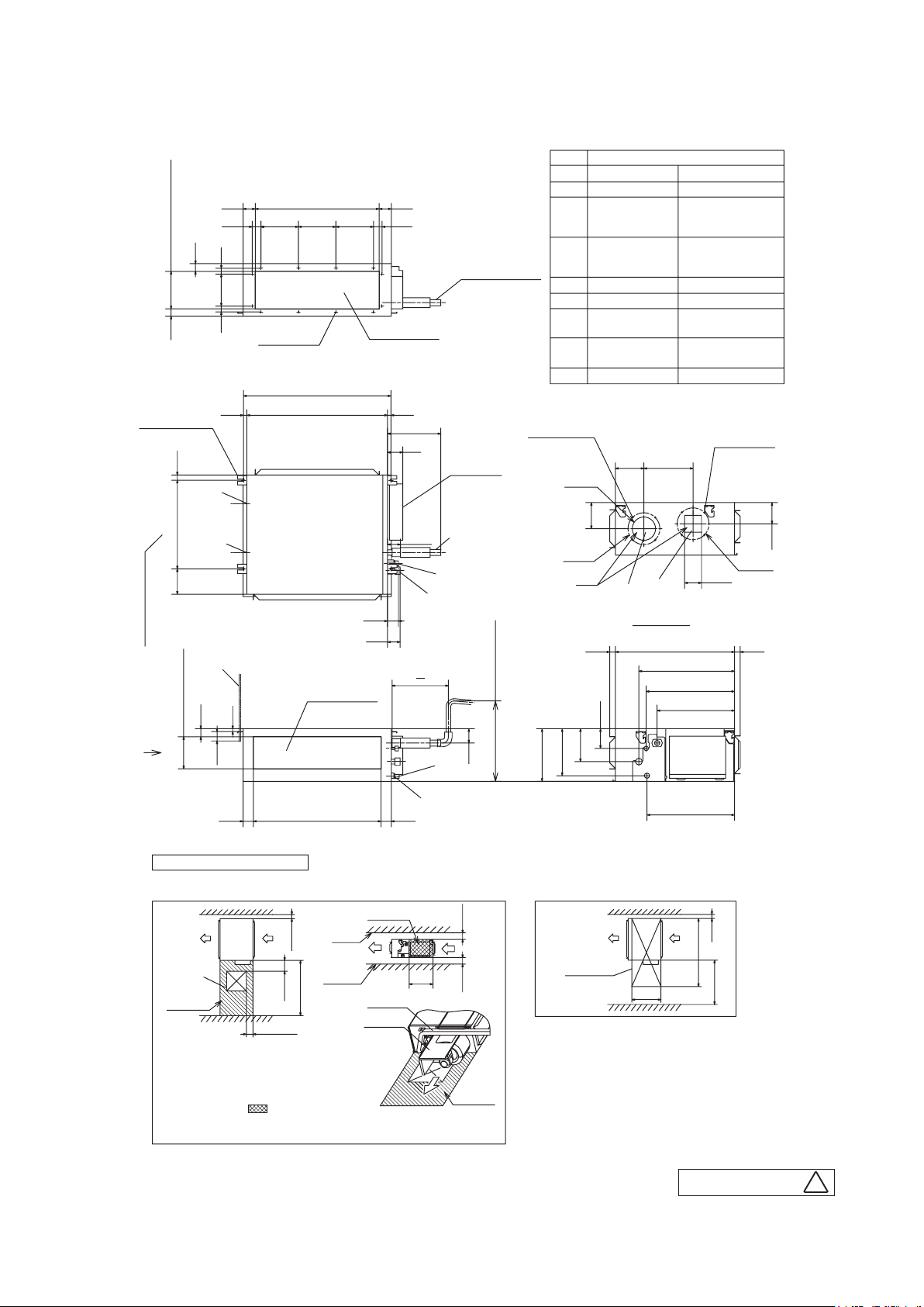
(c) Duct connected-Low / Middle static pressure type (FDUM)
Models FDUM40VF, 50VF
65 660 65
(Duct dimension)
46 200200 46200
(Duct dimension)
41
20039
Hanger plate for
suspension bolt
28472135
3117031
12-φ4
Holes for
tapping screw
(Suspension bolts pitch)
786
Return air duct
18 750 18
284
81
Drain hose piece
(Accessory)
(Installed on site)
Control box
Holes for
tapping screws
F
G
69
1
C
B
A
58
(Suspension bolts pitch)
E
Air supply duct
43
(Duct dimension)
170
15
50
67
295~325
D
76
(Max. drain lift)
or less
600
280
'17 • PAC-T-256
Symbol
A
Gas piping
B
Liquid piping
C1
Drain piping
Drain piping
C2
(Gravity drainage)
D
Hole for wiring
Suspension bolts
E
Outside air opening
F
for ducting
Air outlet opening
G
for ducting
H
Inspection hole
Note(1) The model name label is attached on the lid of
the control box.
4-φ4
Content
152 262
φ12.7(1/2")(Flare)
φ6.35(1/4")(Flare)
VP25(I.D.25, O.D.32)
VP20(I.D.20, O.D.26)
(M10)
(φ150)(Knock out)
(φ125)(Knock out)
(450X450)
4-φ4
Holes for
tapping screws
φ124
139
φ170
Hole
□90
G
F
113
φ170
View M
635 3030
510
471
413
250
105
175
C
370
2
-
20 20
Note (a)
17
or more
or more
-
55 680 55
Space for installation and service
Select either of two cases to keep space for installation and services.
(Case 1) From side of unit
H
Note (a)
Notes (a) There must not be obstacle to draw
out fan unit. For fan unit maintenance,
refer to page 56.
(b) Install refrigerant pipes,
drain pipe,and wiring so as
not to cross marked area.
(c) The case that pipes are installed to upper (bottom) of fan unit,
keep space of 60mm or more to upper (bottom) of unit.
(Duct dimension)
100
or more
~
or more
200
150
1000
100~200
Note (b)
Slab
Ceiling
Pipe (c)
Fan unit
467
(Case 2) From bottom of unit
Inspection
hole
620
PJG000Z002
Unit:mm
100
or more
1100
600
or more
B
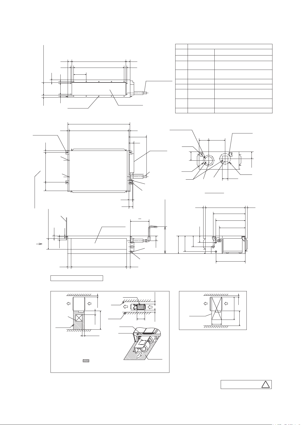
Model FDUM60VF
65 860 65
(Duct dimension)
41
20039
Hanger plate for
suspension bolt
46
3117031
Holes for
tapping screw
18 950 18
4×200=800
200
14-φ4
(Suspension bolts pitch)
986
28472135
(Duct dimension)
46
Return air duct
284
81
Drain hose piece
(Accessory)
(Installed on site)
Holes for
tapping screws
Control box
'17 • PAC-T-256
Symbol
A
Gas piping
B
Liquid piping
C1
Drain piping
Drain piping
C2
(Gravity drainage)
D
Hole for wiring
E
Suspension bolts
Outside air opening
F
for ducting
Air outlet opening
G
for ducting
H
Inspection hole
Note(1) The model name label is attached on the lid of the control box.
4-φ4
152 262
Content
φ12.7(1/2")(Flare)
φ6.35(1/4")(Flare)
VP25(I.D.25, O.D.32)
VP20(I.D.20, O.D.26)
(M10)
(φ150)(Knock out)
(φ125)(Knock out)
(450X450)
4-φ4
Holes for
tapping screws
φ124
M
F
G
69
A
B
C
1
φ170
Hole
139
G
F
View M
113
φ170
□90
58
(Suspension bolts pitch)
67
63530 30
510
E
Air supply duct
43
(Duct dimension)
170
15
50
55 880 55
Space for installation and service
Select either of two cases to keep space for installation and services.
(Case 1) From side of unit
H
Note (a)
Notes (a) There must not be obstacle to draw
out fan unit. For fan unit maintenance,
refer to page 56.
(b) Install refrigerant pipes,
drain pipe,and wiring so as
not to cross marked area.
(c) The case that pipes are installed to upper (bottom) of fan unit,
keep space of 60mm or more to upper (bottom) of unit.
(Duct dimension)
100
or more
Ceiling
or more
200
150~
1000
100~200
Slab
Note (b)
Pipe (c)
Fan unit
295~325
D
2
C
370
76
20 20
Note (a)
(Max. drain lift)
or less
600
or more
or more
105
175
250
280
(Case 2) From bottom of unit
Inspection
hole
620
471
413
467
1300
100
or more
600
or more
-
18
PJG000Z003
A
-
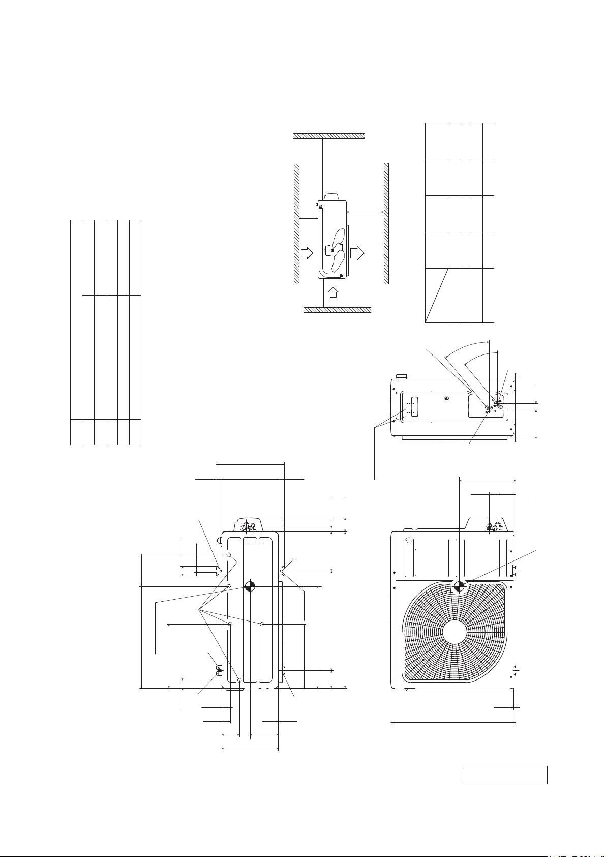
(2) Outdoor units
Models SRC40ZSX-S, 50ZSX-S, 60ZSX-S
'17 • PAC-T-256
φ12.7(1/2")(Flare)
Content
A Service valve connection(Gas side)
Symbol
M10-12×4 places
φ20×5 places
φ6.35(1/4")(Flare)
Service valve connection(Liquid side)
Drain discharge hole
E Anchor bolt hole
D
B
C Pipe/cable draw-out hole
L4
Service
space
( )
L3
Inlet
L2
Notes
(1) The unit must not be surrounded by walls on the four sides.
(2) The unit must be fixed with anchor bolts. An anchor bolt must not
protrude more than 15mm.
(3) If the unit is installed in the location where there is a possibility of
strong winds, place the unit such that the direction of air from the
outlet gets perpendicular to the wind direction.
(4) Leave 200mm or more space above the unit.
(5) The wall height on the outlet side should be 1200mm or less.
(6) The model name label is attached on the front side of the unit.
351.6
24.3312.514.8
L1
Outlet
Inlet
Terminal block
Ⅳ
Ⅲ
I Ⅱ
Minimum installation space
installation
Examples
Size
C
180
Open
280
Open
75
280
100
Open
L2
L1
40°
40°
80
80
80
100
L3
Open
250
Open
250
L4
B
290
Unit:mm
A
33.5148.4
93 42.5
520.6 161
Center of gravity
327.3
50.6
38.6
12
D
E
17.9
E
E
2-12X16
Slot hole
2-R
35.6
43.5
90.6
145
290
327.3
E
83.5
71.2
Center of gravity
800
520
89 510 201
12.4
640
RCT000Z020
-
19
-
A
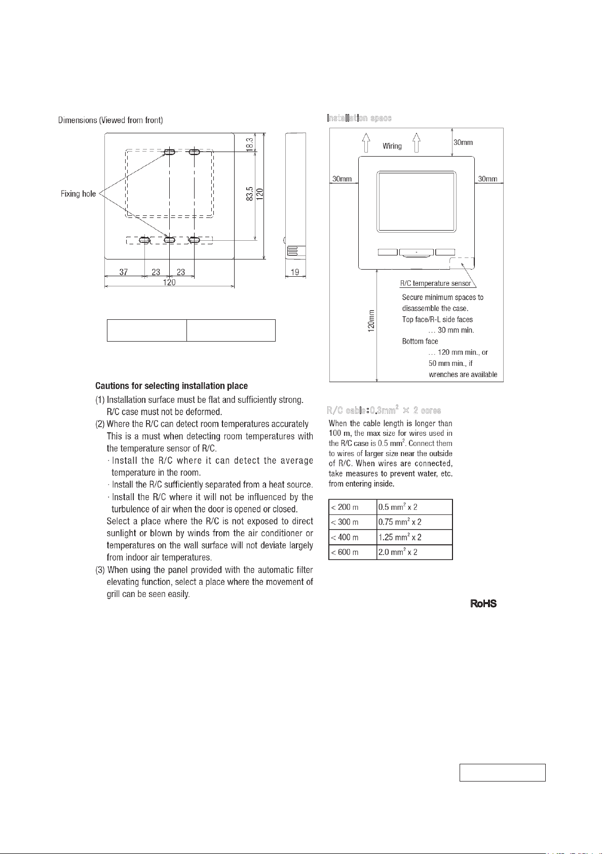
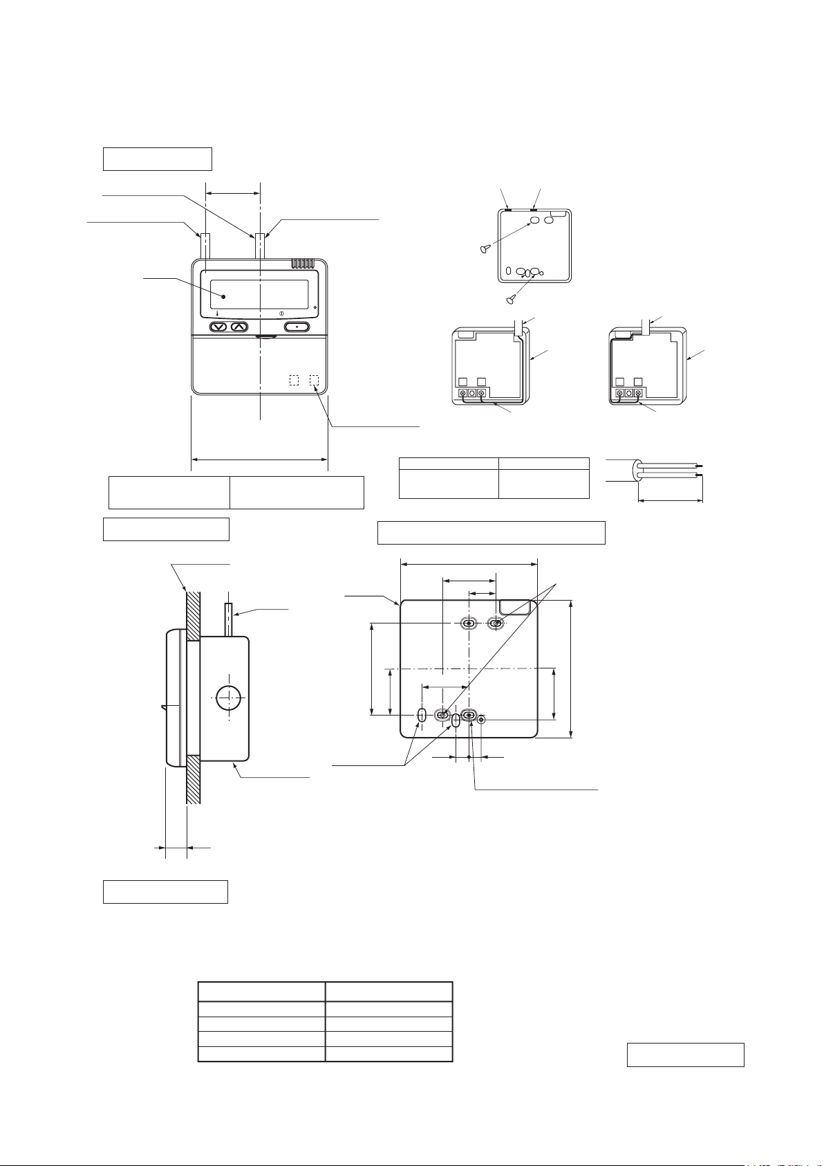
(3) Remote control (Option parts)
Wired remote control
Model RC-EX3
Installation sp
'17 • PAC-T-256
ce
a
Exterior appearance
(Munsell color)
white
Pearl White
(N8.5) near equivalent
‐
R/C
allen
c
e:0
abl
.3mm
2
c
2
cores
cores
es
o
r
cores
cores
dapted to R
oHS
directive
×
PJZ000Z321
-
-
20
'17 • PAC-T-256
Upper cace
Wiring outlet
Model RC-E5
Exposed mounting
0.3mm2×2 cores.
In case of pulling out
from upper left
L C D
Exterior appearance
(Munsell color)
Embedded mounting
48
In case of pulling out
from center
TEMP ON/OFF
ڧ120
Pearl white
(N8.5) near equivalent
Cut off the upper thin part of remote control lower case with a nipper or knife,
and grind burrs with a file etc.
X, Y terminal block
Attach M3 screw
with washer
The peeling-off length of sheath
Pulling out from upper left
Remote control installation dimensions
In case of pulling out
from upper left
XY
In case of pulling out from
upper left
X wiring : 215mm
Y wiring : 195mm
Lower case
Upper
Board
Lower
Wiring
Pulling out from center
X wiring : 170mm
Y wiring : 190mm
In case of pulling out
from center
Upper part
Lower part
Sheath
Upper cace
In case of pulling out from center
Upper
Board
YX
Lower
The peeling-off length
Sheath
Wiring
of sheath
Wall surface
Wiring
Electrical box
䠄Not included䠅
Remote
control
outline
83.5
Wiring oulet
12×7 slot hole
42
120
46
23
44
11.5 11
9.5×5 slot hole 䠄4 places䠅
Tighten the screws after
cutting off the thin part of
screw mounting part.
120
45
Installation hole
䠄1䠅 Installation screw for remote control
19
M4 Screw (2 pieces)
Wiring specifications
(1) If the prolongation is over 100m, change to the size below.
But, wiring in the remote control case should be under 0.5mm2. Change the wire size outside of
the case according to wire connecting. Waterproof treatment is necessary at the wire connecting
section. Be careful about contact failure.
Unit:mm
Length Wiring thickness
100 to 200m
Under 300m
Under 400m
Under 600m
0.5mm
0.75mm
1.25mm
2.0mm
2
×2 cores
2
×2 cores
2
×2 cores
2
×2 cores
-
21
PJZ000Z295
-
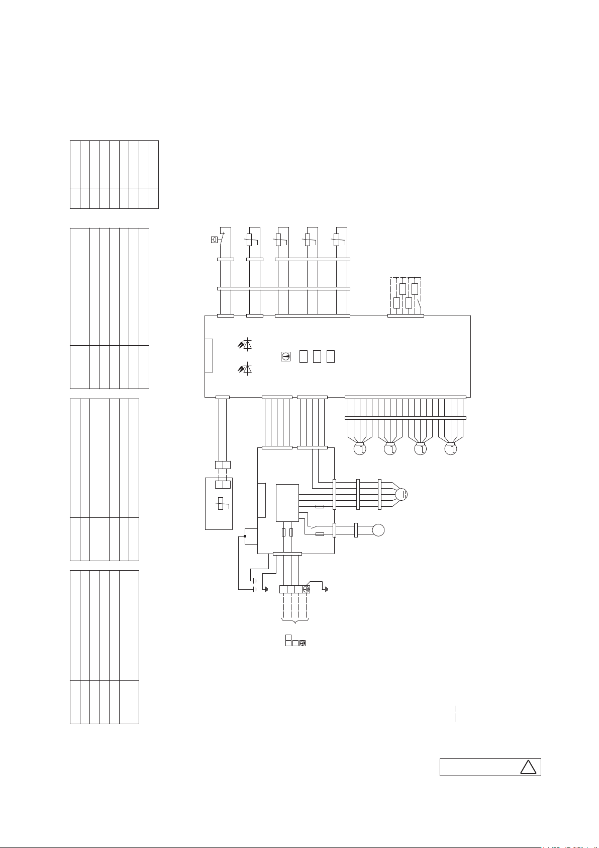
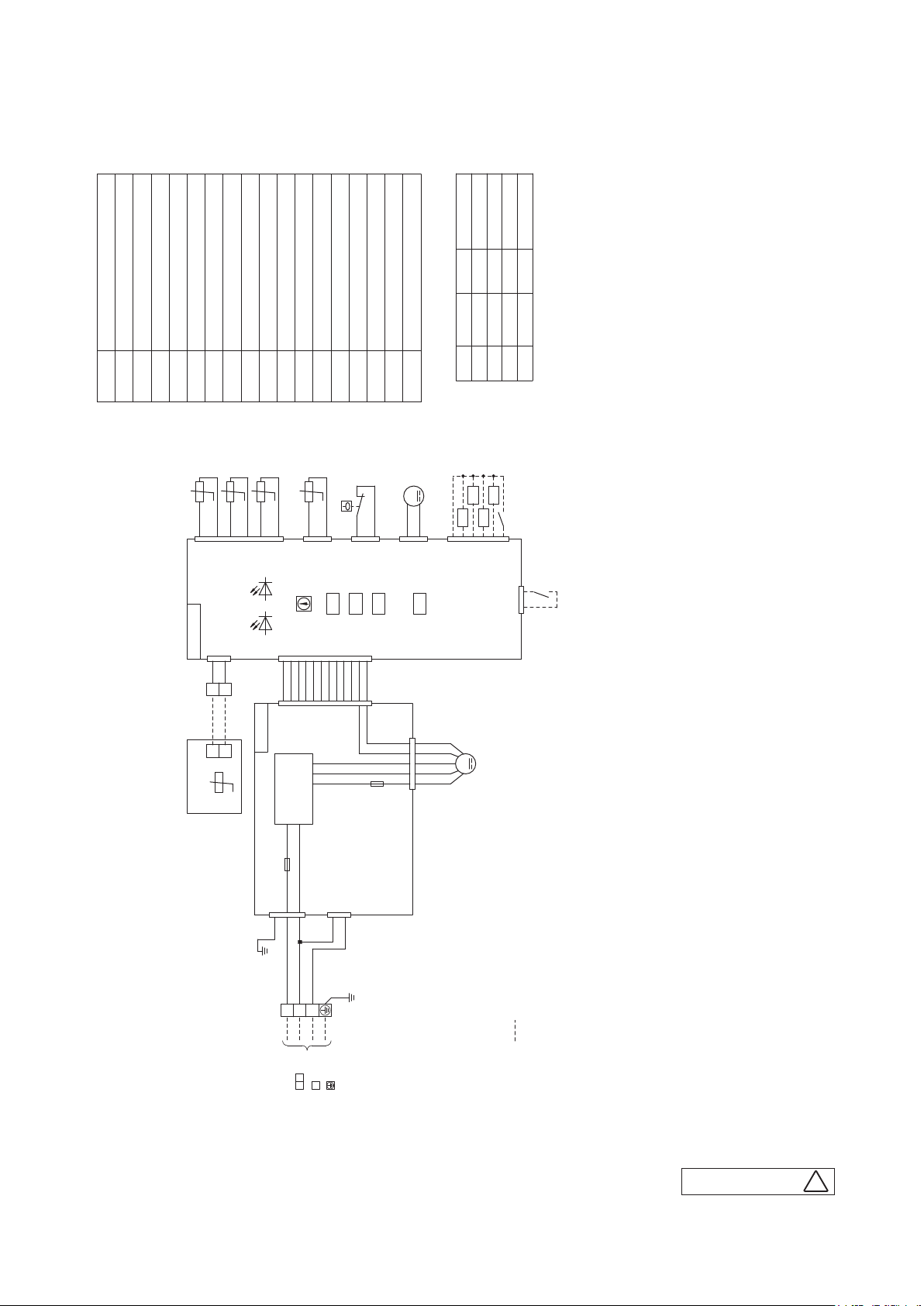
3. ELECTRICAL WIRING
(1) Indoor units
(a) Ceiling cassette-4 way compact type (FDTC)
Models FDTC40VF, 50VF, 60VF
OrangeOR
Blue
BL
BK Black
Mark Color
Color Marks
BR Brown
RedRD
Yellow
White
Y
WH
Yellow /Green
Y/GN
-R1
-A
i
i
Th
FS
Th
-R2
i
Th
-R3
i
Th
'17 • PAC-T-256
Thermistor(Remote control)
(□ mark)
TB1 Terminal block(Power source)
Thc
TB2 Terminal block(Signal line)( □mark)
Remote control communication
Louver motor
Indication lamp(Red-Inspection)
address
LM1~4DM
SW2
LED・3
Relay for DMX4
Thermistor(Heat exchanger)
Thermistor(Return air)
■ mark Closed-end connector
Thi-R1,2,3
Thi-A
Plural units Master/Slave setting
Model capacity settingSW6
Operation check,Drain motor test runSW7-1
SW5
RD
1
WH
1
WH
1
Control PCB
CNB
1
WH
X
TB2
X
Remote control
CNI
WH
BK
C
Th
RD
2
WH
2
WH
2
BL
WH
CNI2
BKt°BK
1
BL
3
BL
1
CNH
2
BL
4
BL
2
BK
WH
CNH2
BKt°BK
1
RD
5
RD
1
SW2
BKt°BK
2
3
4
Y
Y
RD
6
7
8
Y
Y
RD
2
3
4
Y
CNN
SW6
SW5
BKt°BK
5
BK
9
BK
5
SW7
6
BK
10
BK
6
BK
CNN2
WH
CNC
(Compressor ON)
(Heating)
(Operation)
XR2
XR1
XR3
Option
1
2
345
+12
BL
CNT
(Inspection)
XR4
XR5(Remote operation input:volt-free contact)
6
LED・2 LED・3
Power circuit
3
WH
F201(3.15A)
1
BL
2
BL
CNW4
21345
BLBLBLBLBL
1
2
345
BL
CNW1
F202
X4
F203
WH
CNW0
Y/GN
3
TB1
WH
1
2
34567
BKBKBKBKBK
1
2
345
BKBKBKBKBKBKBKBKBKBKBKBKBKBKBKBKBKBKBKBK
1
2
345
M
LM1
CNM3RDCNM4
WH
CNM
5 6 4 3 2
1 4 5 6 7
RD BL BR OR WH
RD BL BR OR WH
(1.0A)
2 1
Y Y
WH BR
1 3
WH
CNR
BL
(0.16A)
CNR2
CNJ
9
8
101112
BKBKBK
BK10BK11BK12BK13BK14BK15BK16BK17BKBK18BK19BK20BK
6
9
7
8
1
2
34512
M
LM2MLM3
WH
M
I
5 6 4 3 2
FM
RD BL BR OR WH
M
1~
DM
1314151617
34512
LM4
18
345
M
19
20
WH
CNJ2
BK
RD
CNW3
3
Y
1
2
345
RDRDRDRDRD
1
2
345
RD
CNW2
Y
t°
Power PCB
Y/GN
F200(3.15A)
5
7
Y/GN
RD
Y/GN
Y/GN
Y/GN
1
Float switch
Drain motor
Fan motor
ConnectorCNB~Z
Meaning of marks
F200~203 Fuse
Indication lamp
I
FS
FM
LED・2
(Green-Normal operation)
1 2
3
Power source line
Signal line
Earth
indoor unit and outdoor unit
Connecting line between
[ ]
-
-
22
2
inside unit and outside unit.
and TB2 is the terminal block for weak current (remote control).
indoor unit and outdoor unit),
3. See the wiring diagram of outside unit about the line between
2. TB1 is the terminal block for heavy current (connecting line between
Notes 1. indicates wiring on site.
PJA003Z340
4. Use twin core cable(0.3mm x 2)at remote control line.
5. Do not put remote control line alongside power source line.
D
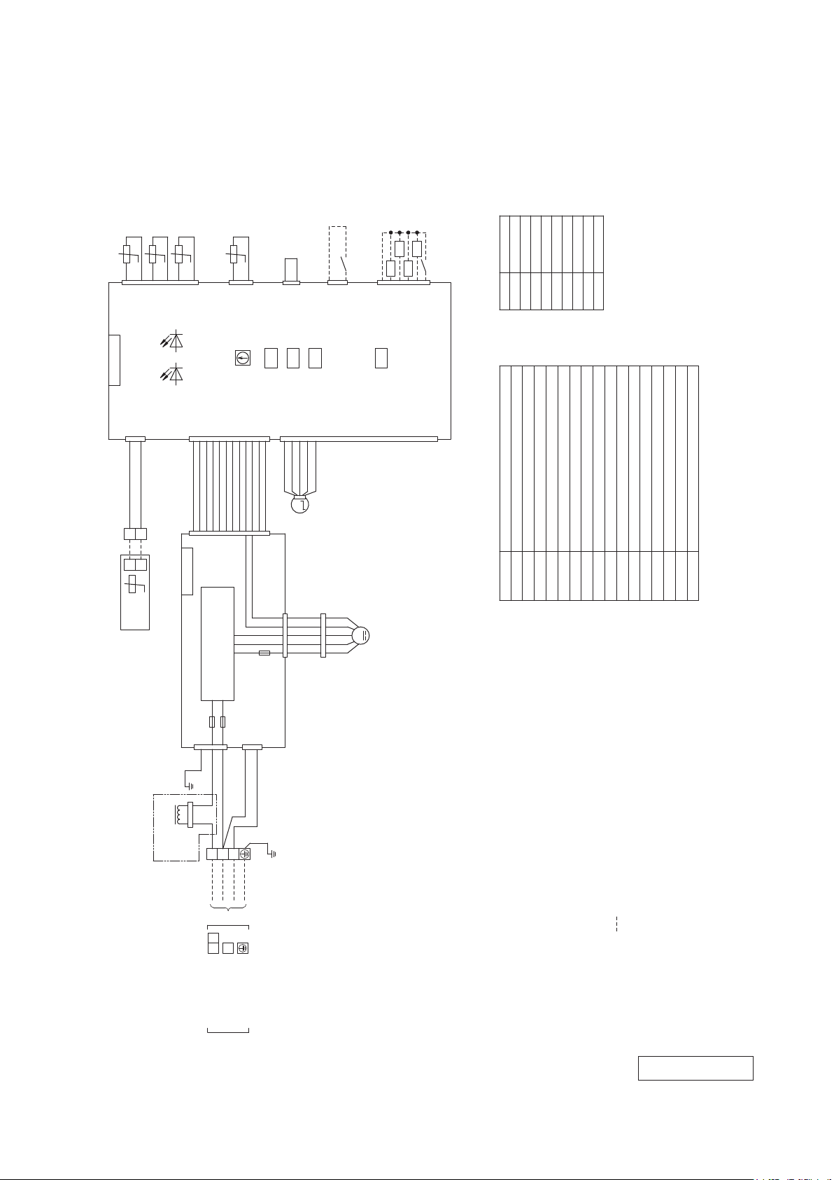
(b) Ceiling suspended type (FDE)
Models FDE40VG, 50VG, 60VG
t°
BK
1
CNH
SW2
Thi-A
BK
2
BK
1
SW5
WH
2
BL
CNI
SW6
SW7
Thi-R1
Thi-R2
t°
t°
BK
BK
BK
2
345
1
CNN
Control PCB
LED・2 LED・3
Thi-R3
t°
BK
BK
BK
6
YE
+12
2
1
BL
CNTA
Prepare on site
(Remote operation:volt-free contact)
1
+12
WH
CNZ
FOR HA
(Operation)
XR1
2
(Heating)
XR2
345
CNT
(Compressor ON)
(Inspection)
XR4
(Remote operation:
XR3
XR5
6
BL
'17 • PAC-T-256
volt-free contact)
Color
Black
Blue
Mark
BKBLBR
Color marks
Brown
Orange
OR
PinkPK
Red
RD
White
Yellow
YE
WH
Yellow/Green
YE/GN
1
WH
X
TB2
X
Remote
WH
CNB
3
BK
Y
Y
t°
Thc
control
2
1
WHWHWHWHWHWHWHWHWHWHWH
2
1
Power PCB
WH
CNW0
1
YE/GN
※1
L
WH
CNW2
6
345
7
8
6
345
7
8
WH
CNW1
Power circuit
F1(3.15A)
F2(3.15A)
3
5
RD
WH
9
101112
9
101112
CNW3
1
BL
WH
F3
WH
3
345
M
WH
8
101112
1314151617
19
18
20
Parts nameMark
Fan motor
ConnectorCNB-Z
Meaning of marks
WH
CNF1
BL
YE
WH
M
BK
I
RD
1 4 5 6 7
FM
Indication lamp(Red-Inspection)
Indication lamp(Green-Normal operation)
Fuse(Power PCB)F1-3
FMI
Louver motorLM
LED・2
LED・3
SW2 Remote control communication address
Powerful mode Valid/Invalid
Model capacity settingSW6
Terminal block(Power source)TB1
Operation check,drain motor test runSW7-1
SW7-3
SW5 Plural units Master/Slave setting
2
Thermistor(Return air)
Thermistor(Heat exchanger)
Thermistor(Remote control)
Terminal block(Signal line)TB2
Thi-A
Thi-R1,2,3
Thc
2)at remote control line. See spec
x
2
1
BL
PK
BRORRD
WH
2
345
1
LM
CNM1
BL
YE
WH
BK
RD
1 4 5 6 7
(2.0A)
WH
CNJ
6
9
7
2
3
3
Signal line
Earth
YE/GN
TB1
RD
1
CNWR2
WH
21
Power source line
Connecting line between
indoor unit and outdoor unit
-
23
sheet of remote control in case that the total length is more than 100m.
4. Do not put remote control line alongside power source line.
Notes 1. indicates wiring on site.
2. See the wiring diagram of outside unit about the line between
indoor unit and outdoor unit.
5. Section 1(※1) is provided on the models FDE100-140 only.
3. Use twin core cable(0.3mm
PFA004Z028
-
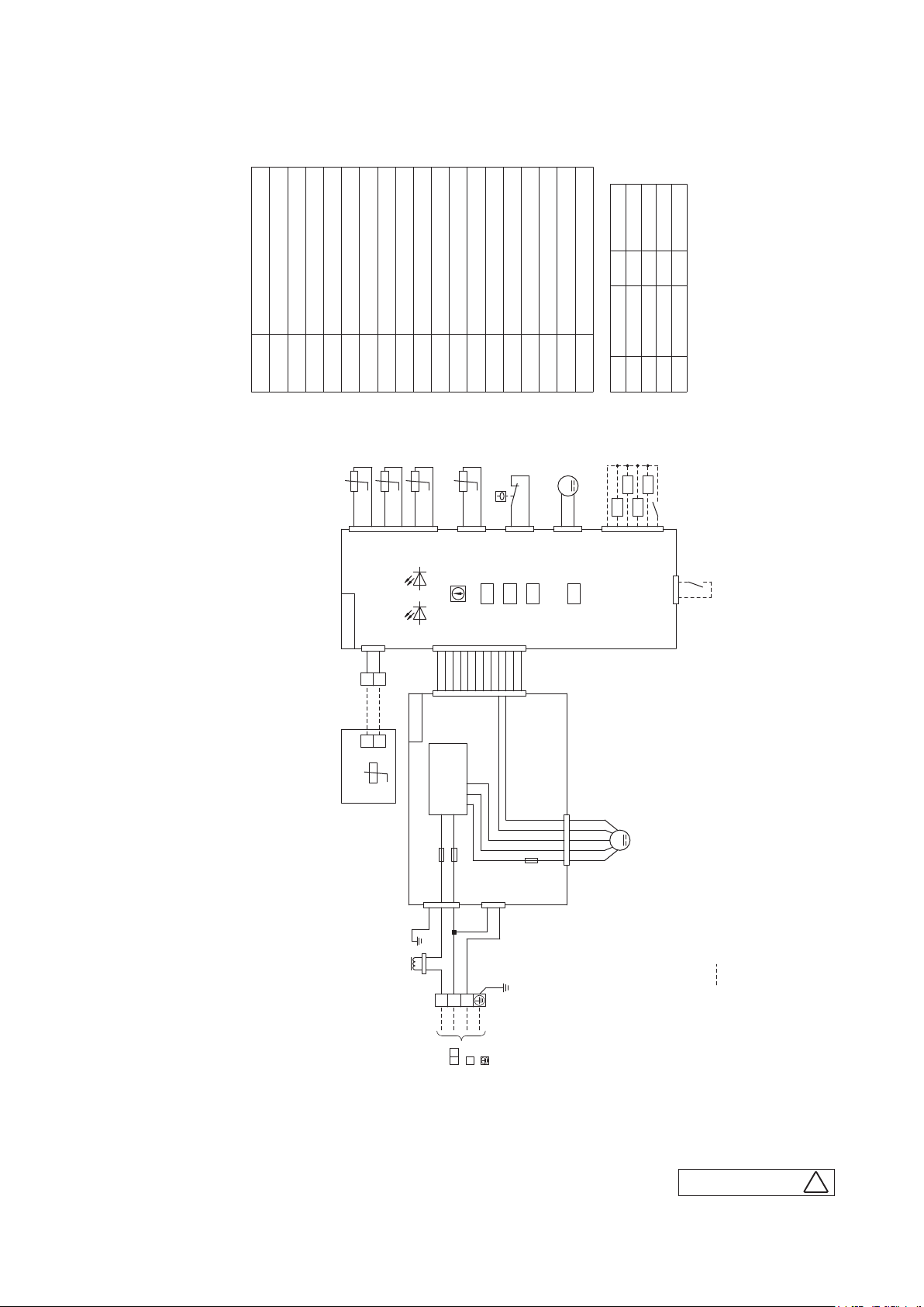
(c) Duct connected-Low / Middle static pressure type (FDUM)
Models FDUM40VF, 50VF
ColorMark
RD Red
WH White
YE Yellow
YE/GN Yellow/Green
'17 • PAC-T-256
FuseF1~3
ConnectorCNB~Z
Drain motor
Fan motor(with thermostat)
1
I
FM
DM
Meaning of marks
Float switch
Indication lamp(Green-Normal operation)
Reactor
LED・2
FS
L
-R1
i
Th
t°
RD
RD
12345
CNB
1
Control PCB
WH
X
X
C
Th
Remote control
Powerful mode Valid/InvalidSW7-3
Indication lamp(Red-Inspection)
Remote control communication address
LED・3
SW2
-R2
i
Th
t°
YE
YE
BK
YE
CNN
LED・2 LED・3
WH
3
BK
Y
TB2
Y
Operation check, Drain motor test runSW7-1
Model capacity setting
Plural units Master/Slave setting
SW5
SW6
-R3
i
Th
-A
i
Th
t°
BK
BKt°BK
6
1
BK
CNH
SW2
WH
CNW2
34567
1
2
WHWHWH
WHWHWH
WH
567
2
3
4
1
WH
Power PCB
CNW1
Terminal block〔Power source)(□mark)
TB1
FS
RD
2
SW5
9
8
101112
WHWHWH
WH
WH
9
8
101112
t°
Power circuit
Terminal block〔Signal line)(□mark)
TB2
1
CNI
SW6
WH
RD
BL
2
Thermistor〔Remote control)
Thc
SW7
Closed-end connector
Thermistor〔Return air)
Thermistor〔Heat exchanger)
-R1,2,3
-A
i
i
Th
■mark
Th
DM
M
RD
WH
Prepare on site
1
2
+12
WH
CNR
WH
CNZ
For HA
WH
CNM1
ColorMark
Black
BK
Color Marks
(Compressor ON)
(Operation)
(Heating)
XR2
XR1
XR3
12345
+12
BL
CNT
BL Blue
BR Brown
OR Orange
(Inspection)
XR4
XR5(Remote operation
input:volt-free contact)
6
2
BL
1
CNTA
(Remote operation input:
volt-free contact)
F1(3.15A)
F2(3.15A)
WH
CNW0
1
3
5
RD
WH
YE/GN
L
RD
WH
1
2
CNWR2
3
3
1 2
Power source line
Signal line
indoor unit and outdoor unit
Connecting line between
-
-
24
CNW3
1
WH
Earth
WH
3
BL
YE/GN
TB1
M
BK WH YE BL
1 4 5 6 7
F3
RD
(2A)
1
I
FM
2)at remote control line.
x
2
Notes 1. indicates wiring on site.
PJG000Z005
4. Do not put remote control line alongside power source line.
2. See the wiring diagram of outside unit about the line between
inside unit and outside unit.
3. Use twin core cable(0.3mm
D
Model FDUM60VF
ConnectorCNB~Z
Drain motor
FuseF1,4
Float switch
Indication lamp(Green-Normal operation)
Indication lamp(Red-Inspection)
Remote control communication address
Model capacity setting
t°
WH
LED・3
RD
2
CNB
1
X
X
SW2
Thi-R2
YE
345
CNN
WH
3
BK
Y
Y
t°
Plural units Master/Slave setting
SW6
SW5
Thi-R3
t°
t°
YE
BK
YE
LED・2 LED・3
TB2
Power PCB
BK
Fan motor(with thermostat)
FMI2
DM
Meaning of marks
FS
LED・2
Thi-R1
RD
1
Control PCB
C
Th
Remote control
Operation check, Drain motor test runSW7-1
Powerful mode Valid/InvalidSW7-3
BKt°BK
6
1
CNH
SW2
CNW2
34567
2
1
WHWHWH
WHWHWH
WH
567
2
3
4
1
CNW1
Power circuit
Terminal block(Power source)(□mark)
TB1
Thi-A
2
BK
WH
WH
WH
Terminal block(Signal line)(□mark)
Thermistor(Remote control)
Thc
TB2
FS
RD
1
SW6
SW5
9
8
101112
WHWHWH
WH
9
8
101112
CNI
WH
RD
2
BL
F4
Thermistor(Return air)
Thi-A
SW7
(2A)
Thermistor(Heat exchanger)
Thi-R1,2,3
M
RD
1
+12
CNR
For HA
1 4 5 6 7
ColorMark
RD Red
WH White
ColorMark
Closed-end connector
Black
BK
Color Marks
BL Blue
■mark
(Operation)
(Heating)
(Inspection)
DM
WH
WH
WH
CNZ
2
BK
CNM2
(Compressor ON)
XR2
XR4
XR1
XR3
Prepare on site
2
345
1
+12
BL
CNT
CNTA
M
BK WH YE BL
RD
FMI2
YE Yellow
YE/GN Yellow/Green
BR Brown
OR Orange
XR5(Remote operation
input:volt-free contact)
6
2
BL
1
(Remote operation input:
volt-free contact)
'17 • PAC-T-256
F1(5A)
WH
CNW0
3
5
1
RD
WH
YE/GN
1
indoor unit and outdoor unit
Connecting line between
WH
CNW3
3
1
BL
WH
YE/GN
3
2
TB1
3
1 2
Earth
Power source line
Signal line
[ ]
-
25
)at remote control line.
x 2
2
Notes 1. indicates wiring on site.
4. Do not put remote control line alongside power source line.
2. See the wiring diagram of outside unit about the line between
inside unit and outside unit.
3. Use twin core cable(0.3mm
-
PJG000Z028
B
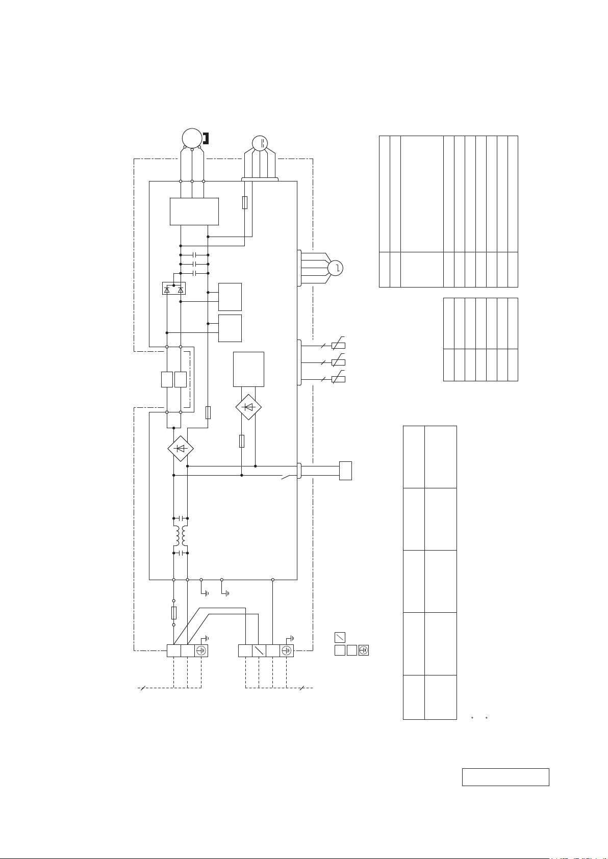
(2) Outdoor units
Models SRC40ZSX-S, 50ZSX-S, 60ZSX-S
(RD)
UP
POWER
TRANSISTOR
MS
(WH)
VWU
'17 • PAC-T-256
CM
3~
(BK)
V
W
N
F3
T 1A L 250V
M
(WH)
CNFAN
FMo
+
++
T2
T12
(BL)
(YE)
L1
L2
(BL)
(YE)
T1
T11
+
-
DIODE
STACK1
~
~
PCB ASSY PCB1
F8
PAM
PAM
DIODE
250V 20A
CIRCUIT
CIRCUIT
SWITCHING
+
STACK2
~
F1
POWER
CIRCUIT
-
~
F 3.15A L 250V
(RD)
(WH)
(BK)
CNTH CNEEV
CN20S
M
EEV
Item Description
20S Solenoid coil for 4-way valve
CNFAN
CNEEV
CN20S Connector
EEV Electric expansion valve(coil)
CM Compressor motor
CNTH
TH3 Discharge pipe temp. sensor
TH2 Outdoor air temp. sensor
TH1 Heat exchanger sensor
L1,2 Reactor
FMo Fan motor
Meaning of marks
t゜
t゜
t゜
2 2 2
TH1 TH2 TH3
20S
Connecting cable
Power cable length
Color
BK Black
Mark
Color marks
x 4
2
wire size x number*
(m)
BL Blue
RD Red
YE Yellow
WH White
Yellow/Green
YG
3
220V 60Hz
220-240V 50Hz
Power source
1 Phase
R.IN
(BK)
F4
(BK)
L
TB1
BLOCK 1
TERMINAL
S.IN
G1
(WH)
(YG)
250V 20A
N
G2
(YG)
(YG)
(BK)
(WH)
TB2
BLOCK 2
TERMINAL
C-2
(RD)
]
N
N
1
2
(YG)
3
4
2
3
1
POWER WIRES
SIGNAL WIRE
EARTH WIRE
TO INDOOR UNIT
MAX running current Power cable
Power cable, indoor-outdoor connecting wires
x 3 13 1.5mm
2
2.0mm
wire size x number*(A)
15
Model name
SRC50ZSX-S
Switchgear or circuit breaker capacity should be chosen according to national or regional electricity
The power cable specifications are based on the assumption that a metal or plastic conduit is used
with no more than three cables contained in a conduit and a voltage drop is 2%. For an installation
The wire numbers include earth wire(Yellow/Green)*regulations.
SRC60ZSX-S
falling outside of these conditions, please follow the national or regional electricity regulations.
[
RWC000Z298
-
-
26
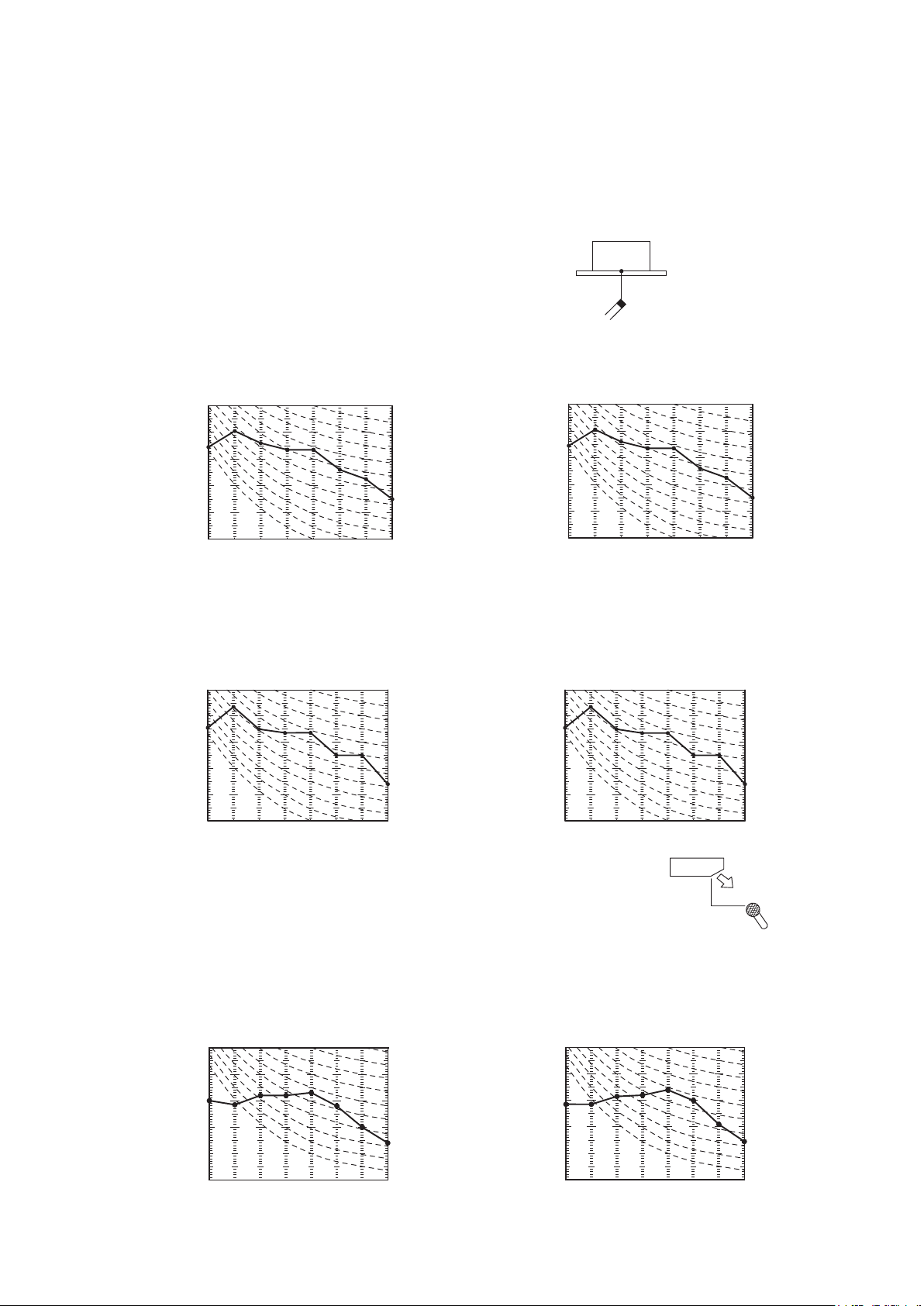
4. NOISE LEVEL
Heating noise level 47 dB (A) at P-HIGH
39 dB (A) at MEDIUM
32 dB (A) at LOW
N60
40
50
40
50
63
125
250 500 1000 2000 4000 8000
10
20
30
10
20
30
N50
N40
N30
N20
60
60
N10
Mid octave band frequency (Hz)
Souud pressure level
(standard 2×10
-5
Pa)
Models FDE40VG, 50VG
Noise level 46 dB (A) at P-HIGH
38 dB (A) at HIGH
36 dB (A) at MEDIUM
31 dB (A) at LOW
60
60
Model FDE60VG
Noise level 47 dB (A) at P-HIGH
41 dB (A) at HIGH
37 dB (A) at MEDIUM
32 dB (A) at LOW
63 125 250 500 1000 2000 4000 8000
20
10
30
40
50
60
20
10
30
40
50
60
N30
N40
N20
N50
N60
Souud pressure level (dB)
(Standard 2×10
-5
Pa)
Mid octave band frequency (Hz)
31 dB (A) at LOW
Model FDE60VG
Noise level 47 dB (A) at P-HIGH
41 dB (A) at HIGH
37 dB (A) at MEDIUM
32 dB (A) at LOW
Model FDE60VG
Noise level 47 dB (A) at P-HIGH
41 dB (A) at HIGH
37 dB (A) at MEDIUM
32 dB (A) at LOW
60
60
32 dB (A) at LOW
Notes (1) The data are based on the following conditions.
Ambient air temperature: Indoor unit 27℃WB. Outdoor unit 35℃DB.
(2) The data in the chart are measured in an anechoic room.
(3) The noise levels measured in the field are usually higher than the data because of reflection.
(1)
Indoor units
(a) Ceiling cassette-4way compact type (FDT)
Measured based on JIS B 8616
Mike position as right
1.5m
Mike (at center & below unit)
N60
40
50
40
50
63
125
250 500 1000 2000 4000 8000
10
20
30
10
20
30
N50
N40
N30
N20
60
60
N10
Souud Pressure Level
(standard 2×10
-5
Pa)
Mid Octave Band Frequency (Hz)
N60
40
50
40
50
63
125
250 500 1000 2000 4000 8000
10
20
30
10
20
30
N50
N40
N30
N20
60
60
N10
Souud Pressure Level
(standard 2×10
-5
Pa)
Mid Octave Band Frequency (Hz)
N60
40
50
40
50
63
125
250 500 1000 2000 4000 8000
10
20
30
10
20
30
N50
N40
N30
N20
60
60
N10
Souud Pressure Level
(standard 2×10
-5
Pa)
Mid Octave Band Frequency (Hz)
Noise level 39 dB (A) at P-HIGH
31 dB (A) at MEDIUM
30 dB (A) at LOW
33 dB (A) at HIGH
Noise level 46 dB (A) at P-HIGH
31 dB (A) at MEDIUM
30 dB (A) at LOW
33 dB (A) at HIGH
Noise level 46 dB (A) at P-HIGH
33 dB (A) at MEDIUM
31 dB (A) at LOW
35 dB (A) at HIGH
N60
40
50
40
50
63
125
250 500 1000 2000 4000 8000
10
20
30
10
20
30
N50
N40
N30
N20
60
60
N10
Souud Pressure Level
(standard 2×10
-5
Pa)
Mid Octave Band Frequency (Hz)
N60
40
50
40
50
63
125
250 500 1000 2000 4000 8000
10
20
30
10
20
30
N50
N40
N30
N20
60
60
N10
Souud Pressure Level
(standard 2×10
-5
Pa)
Mid Octave Band Frequency (Hz)
N60
40
50
40
50
63
125
250 500 1000 2000 4000 8000
10
20
30
10
20
30
N50
N40
N30
N20
60
60
N10
Souud Pressure Level
(standard 2×10
-5
Pa)
Mid Octave Band Frequency (Hz)
Noise level 51 dB (A) at P-HIGH
37 dB (A) at MEDIUM
35 dB (A) at LOW
40 dB (A) at HIGH
Noise level 51 dB (A) at P-HIGH
40 dB (A) at MEDIUM
37 dB (A) at LOW
42 dB (A) at HIGH
Noise level 51 dB (A) at P-HIGH
41 dB (A) at MEDIUM
38 dB (A) at LOW
43 dB (A) at HIGH
Notes (1) The data are based on the following conditions.
Ambient air temperature: Indoor unit 27℃WB. Outdoor unit 35℃DB.
(2) The data in the chart are measured in an anechoic room.
(3) The noise levels measured in the field are usually higher than the data because of reflection.
(1)
Indoor units
(a) Ceiling cassette-4way type (FDTC)
Models FDTC40VF,50VF
Cooling noise level 47 dB (A) at P-HIGH
42 dB (A) at HIGH
36 dB (A) at MEDIUM
60
50
Pa)
-5
40
30
30 dB (A) at LOW
Model FDTC60VF
(b) Ceiling suspended type (FDE)
Models FDE40VG, 50VG
20
(standard 2×10
Souud pressure level
Cooling noise level 47 dB (A) at P-HIGH
-5
Souud pressure level
10
125
63
Mid octave band frequency (Hz)
60
50
Pa)
40
30
20
(standard 2×10
10
125
63
Mid octave band frequency (Hz)
N10
250 500 1000 2000 4000 8000
46 dB (A) at HIGH 46 dB (A) at HIGH
39 dB (A) at MEDIUM
30 dB (A) at LOW
N10
250 500 1000 2000 4000 8000
Noise level 46 dB (A) at P-HIGH
38 dB (A) at HIGH
36 dB (A) at MEDIUM
Pa)
50
-5
40
30
20
(Standard 2×10
10
63 125 250 500 1000 2000 4000 8000
Souud pressure level (dB)
Mid octave band frequency (Hz)
Measured based on JIS B 8616
Mike position as right
60
N60
50
N50
40
N40
30
N30
20
N20
10
60
N60
50
N50
40
N40
30
N30
20
N20
10
N60
50
N50
40
N40
30
N30
20
N20
10
Heating noise level 47 dB (A) at P-HIGH
Souud pressure level
Measured based on JIS B 8616
Mike position as right
Heating noise level 47 dB (A) at P-HIGH
-5
Souud pressure level
Model FDE60VG
Souud pressure level (dB)
-
27
-
'17 • PAC-T-256
1.5m
Mike (at center & below unit)
42 dB (A) at HIGH
36 dB (A) at MEDIUM
60
50
Pa)
-5
40
30
20
(standard 2×10
10
125
63
Mid octave band frequency (Hz)
Pa)
(standard 2×10
60
50
40
30
20
10
125
63
Mid octave band frequency (Hz)
Noise level 47 dB (A) at P-HIGH
41 dB (A) at HIGH
37 dB (A) at MEDIUM
Pa)
50
-5
40
30
20
(Standard 2×10
10
63 125 250 500 1000 2000 4000 8000
Mid octave band frequency (Hz)
32 dB (A) at LOW
N10
250 500 1000 2000 4000 8000
39 dB (A) at MEDIUM
32 dB (A) at LOW
Unit
N10
250 500 1000 2000 4000 8000
1m
Mike (in front & below unit)
N60
N50
N40
N30
N20
1m
N60
N50
N40
N30
N20
N60
N50
N40
N30
N20
60
50
40
30
20
10
60
50
40
30
20
10
50
40
30
20
10
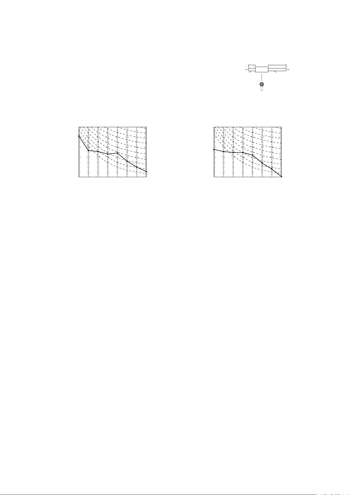
'17 • PAC-T-256
(c) Duct connected-Low / Middle static pressure type (FDUM)
(c) Duct connected-Low / Middle static pressure type (FDUM)
Measured based on JIS B 8616
Mike position as right
1.5m
1m
Return duct
Supply duct
Mike (at center & below unit)
2m
Air
Unit
(c) Duct connected-Low / Middle static pressure type (FDUM)
Measured based on JIS B 8616
Mike position as right
Model FDUM60VF
Noise level 36 dB (A) at P-HIGH
31 dB (A) at HIGH
28 dB (A) at MEDIUM
25 dB (A) at LOW
Model FDUM71VF1
Noise level 38 dB (A) at P-HIGH
33 dB (A) at HIGH
29 dB (A) at MEDIUM
25 dB (A) at LOW
1.5m
1m
Return duct
Supply duct
Mike (at center & below unit)
2m
Air
Unit
Measured based on JIS B 8616
Mike position as right
Model FDUM71VF1
Noise level 38 dB (A) at P-HIGH
33 dB (A) at HIGH
29 dB (A) at MEDIUM
25 dB (A) at LOW
1.5m
1m
Return duct
Supply duct
Mike (at center & below unit)
2m
Air
Unit
Measured based on JIS B 8616
Mike position as right
Model FDUM60VF
Noise level 36 dB (A) at P-HIGH
31 dB (A) at HIGH
28 dB (A) at MEDIUM
25 dB (A) at LOW
Model FDUM71VF1
Noise level 38 dB (A) at P-HIGH
33 dB (A) at HIGH
29 dB (A) at MEDIUM
25 dB (A) at LOW
Souud pressure level
63 125 250 500 1000 2000 4000 8000
20
10
30
40
50
60
20
10
30
40
50
60
N30
N40
N20
N50
N60
Mid Octave Band Frequency (Hz)
Souud Pressure Level
(standard 2×10
-5
Pa)
1.5m
1m
Return duct
Supply duct
Mike (at center & below unit)
2m
Air
Unit
(c) Duct connected-Low / Middle static pressure type (FDUM)
Measured based on JIS B 8616
Mike position as right
Models FDUM40VF, 50VF
Noise level 37 dB (A) at P-HIGH
32 dB (A) at HIGH
29 dB (A) at MEDIUM
26 dB (A) at LOW
Model FDUM60VF
Noise level 36 dB (A) at P-HIGH
31 dB (A) at HIGH
28 dB (A) at MEDIUM
25 dB (A) at LOW
Model FDUM71VF1
Noise level 38 dB (A) at P-HIGH
33 dB (A) at HIGH
29 dB (A) at MEDIUM
25 dB (A) at LOW
63 125 250 500 1000 2000 4000 8000
20
10
30
40
50
60
20
10
30
40
50
60
N30
N40
N20
N50
N60
Mid octave band frequency (Hz)
Souud pressure level
(standard 2×10
-5
Pa)
63 125 250 500 1000 2000 4000 8000
20
10
30
40
50
60
20
10
30
40
50
60
N30
N40
N20
N50
N60
Mid Octave Band Frequency (Hz)
Souud Pressure Level
(standard 2×10
-5
Pa)
1.5m
1m
Return duct
Supply duct
Mike (at center & below unit)
2m
Air
Unit
Models FDUM40VF, 50VF
Noise level 37 dB (A) at P-HIGH
32 dB (A) at HIGH
29 dB (A) at MEDIUM
26 dB (A) at LOW
60
Pa)
50
-5
40
30
20
(standard 2×10
Souud pressure level
10
63 125 250 500 1000 2000 4000 8000
Mid octave band frequency (Hz)
N60
N50
N40
N30
N20
Model FDUM60VF
Noise level 36 dB (A) at P-HIGH
31 dB (A) at HIGH
28 dB (A) at MEDIUM
25 dB (A) at LOW
60
50
40
30
20
-5
Pa)
60
50
40
30
20
(standard 2×10
10
10
63 125 250 500 1000 2000 4000 8000
N60
N50
N40
N30
N20
60
50
40
30
20
10
Mid octave band frequency (Hz)
-
28
-
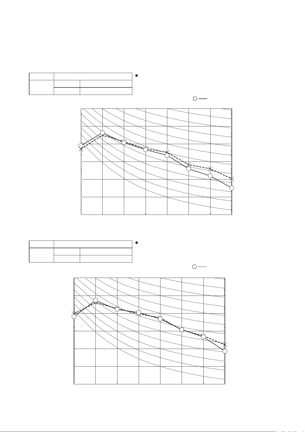
4.2 Outdoor units
(2) Outdoor units
Mid octave band frequency (Hz)
Mike position: at highest noise level in position as mentioned below
Mike position
0.8m
1m
Unit
Mike position
(Center & Low points)
Mid octave band frequency (Hz)
Mike position: at highest noise level in position as mentioned below
Mike position
0.8m
1m
Unit
Mike position
(Center & Low points)
Measured based or JIS B 8616 or JIS C 9612
Mike position: at highest noise level in position as mentined below.
Distance from front side 1m
Models SRC40ZSX-S, 50ZSX-S
'17 • PAC-T-256
Model SRC40ZSX-S, 50ZSX-S
Noise
Level
Cooling 50 dB(A)
Heating 49 dB(A)
70
60
50
Pa)
-5
40
(Standard 2×10
30
Sound pressure level (dB)
20
10
63 125 250 500 1000 2000 4000 8000
Distance from front side 1m
......
×
Cooling,
Heating
70
N70
60
N60
50
N50
40
N40
30
N30
20
N20
10
Model SRC60ZSX-S
Model SRC60ZSX-S
Noise
Level
Cooling 52 dB(A)
Heating 52 dB(A)
70
60
50
Pa)
-5
40
(Standard 2×10
30
Sound pressure level (dB)
20
10
63 125 250 500 1000 2000 4000 8000
Distance from front side 1m
......
×
Cooling,
Heating
70
N70
60
N60
50
N50
40
N40
30
N30
20
N20
10
-
29
-
 Loading...