

Mitsubishi Heavy Industries FDT45KXE6A, FDT112KXE6A, FDTC28KXE6A, FDTC22KXE6A, FDTC45KXE6A Service Manual
...
-
1
-
Manual No. '09·KX-SM -128
INVERTER DRIVEN MULTI-INDOOR UNIT
CLIMATE CONTROL SYSTEM
SERVICE MANUAL
Alternative refrigerant R410A use models
(OUTDOOR UNIT)
• Single use (Used also for combination)
FDC335KXE6-K, 400KXE6, 450KXE6, 504KXE6, 560KXE6, 560KXE6-K, 615KXE6, 680KXE6
• Combination use
FDC753KXE6, 800KXE6, 850KXE6, 900KXE6, 960KXE6, 1010KXE6, 1065KXE6, 1130KXE6,
1180KXE6, 1235KXE6, 1300KXE6, 1360KXE6
(Heat pump type)
KX6 series
FDT28KXE6A
36KXE6A
45KXE6A
56KXE6A
71KXE6A
90KXE6A
112KXE6A
140KXE6A
160KXE6A
FDUM22KXE6
28KXE6
36KXE6
45KXE6
56KXE6
71KXE6
90KXE6
112KXE6
140KXE6
FDUH22KXE6
28KXE6
36KXE6
FDTC22KXE6A
28KXE6A
36KXE6A
45KXE6A
56KXE6A
FDQS22KXE6
28KXE6
36KXE6
45KXE6
56KXE6
FDU71KXE6
90KXE6
112KXE6
140KXE6
224KXE6
280KXE6
FDFU28KXE6
45KXE6
56KXE6
71KXE6
FDTW28KXE6
45KXE6
56KXE6
71KXE6
90KXE6
112KXE6
140KXE6
FDK22KXE6
28KXE6
36KXE6
45KXE6
56KXE6
71KXE6
FDTQ22KXE6
28KXE6
36KXE6
FDFL28KXE6
45KXE6
71KXE6
FDTS45KXE6
71KXE6
FDE36KXE6A
45KXE6A
56KXE6A
71KXE6A
112KXE6A
140KXE6A
(INDOOR UNIT) -KX6 series
-
Regarding the Duct Connected-High static Pressure-type Outdoor Air Processing
Unit Series (FDU500〜1800FKXE6), refer to the DATA BOOK No.'08
•
KX-DB-122
•
Note
updated November 19, 2009

CONTENTS
1 OUTLINE OF OPERATION CONTROL BY MICROCOMPUTER ..................... 1
1.1 Wired remote controller (Option parts) ......................................................1
1.2 Operation control function by the indoor controller ...................................2
1.3 Operation control function by the remote controller .................................. 8
1.4 Operation control function by the outdoor controller .................................9
2 SYSTEM TROUBLESHOOTING PROCEDURE ............................................. 45
2.1 Basics of troubleshooting ........................................................................ 45
2.2 Explanation of troubleshooting ................................................................46
2.3 Contents of troubleshooting ....................................................................47
2.4 Outdoor unit control PCB replacement procedure ................................ 101
2.5 Inverter PCB replacement procedure .................................................... 103
3 ELECTRICAL WIRING ..................................................................................107
3.1 Indoor unit .............................................................................................107
3.2 Outdoor unit ..........................................................................................129
4 PIPING SYSTEM ............................................................................................130
5 APPLICATION DATA .................................................................................... 131
5.1 Installation of indoor unit ........................................................................... 131
(a)
Ceiling cassette-4 way type (FDT) ..................................................... 132
(b)
Ceiling cassette-4 way compact type (FDTC)....................................137
(c)
Ceiling cassette-2 way type (FDTW) ................................................. 142
(d)
Ceiling cassette-1 way type (FDTS) .................................................. 145
(e)
Ceiling cassette-1 way compact type (FDTQ) ................................... 148
(f)
Duct connected-High static pressure type (FDU) .............................. 151
(g)
Duct connected-Middle static pressure type (FDUM) ........................ 157
(h)
Duct connected (Ultra thin)-Low static pressure type (FDQS) ........... 160
(i)
Wall mounted type (FDK) ..................................................................163
(j)
Ceiling suspended type (FDE) ...........................................................166
(k)
Floor standing (with casing) type (FDFL) ........................................... 169
(l)
Floor standing (without casing) type (FDFU) ..................................... 172
(m)
Duct Connected-Compact and Flexible type (FDUH) ........................175
5.2 Electric wiring work instruction .................................................................. 178
5.3 Installation manual of wired remote controller (Option parts) ...................184
5.4 Installation of outdoor unit .........................................................................188
5.5 Instructions for installing the branch pipe set ............................................211
– 1 –
1. OUTLINE OF OPERATION CONTROL BY MICROCOMPUTER
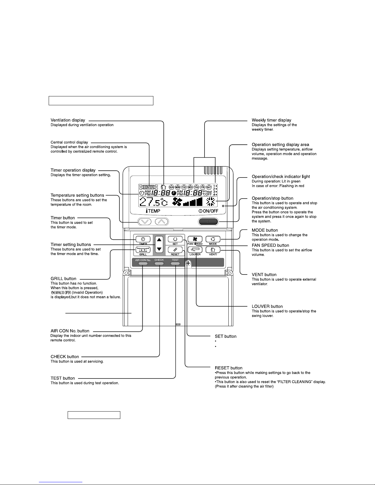
1.1 Wired remote controller (Option parts)
The gure below shows the remote controller with the cover opened. Note that all the items that may be displayed in the liquid crystal
display area are shown in the gure for the sake of explanation.
Characters displayed with dots in the liquid crystal display area are abbreviated.
Pull the cover downward to open it.
* All displays are described in the liguid crystal display for explanation.
The figure below shows the remote control with the cover opened.
Installation of remote control
DO NOT install it on the following places in order to avoid malfunction.
(1) Places exposed to direct sunlight
(2) Places near heat devices
(3) High humidity places
(4) Hot surface or cold surface enough to generate condensation
(5) Places exposed to oil mist or steam directly
(6) Uneven surface
Cover
This button is used to fix the setting.
This button is used to set the silent mode.
– 2 –
1.2 Operation control function by the indoor controller
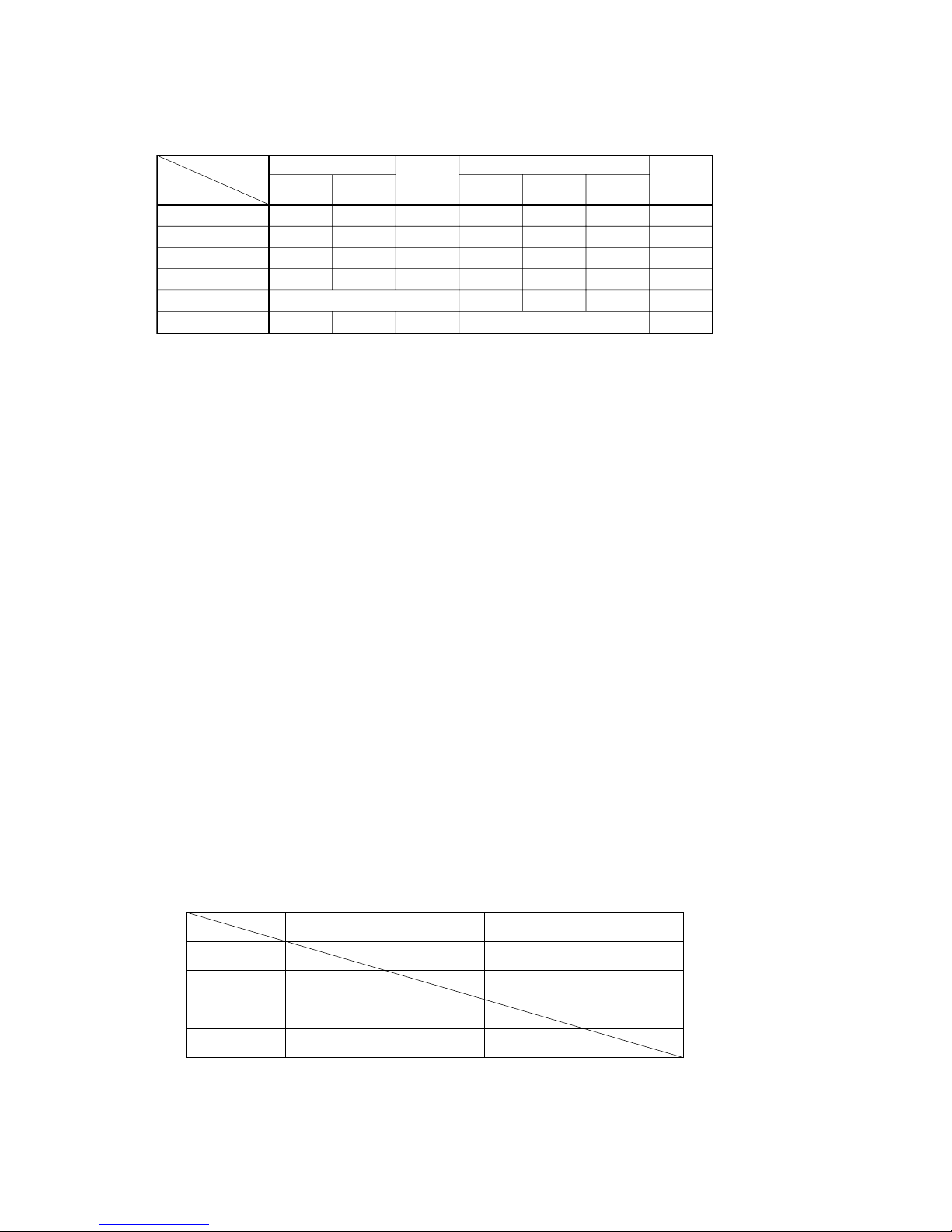
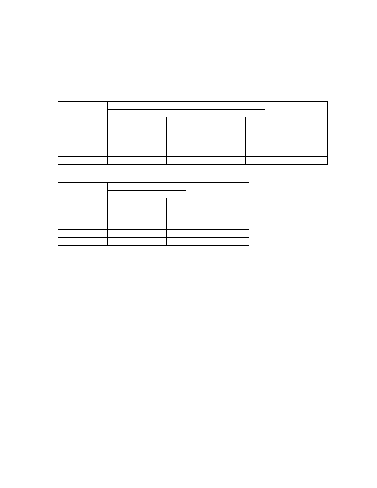
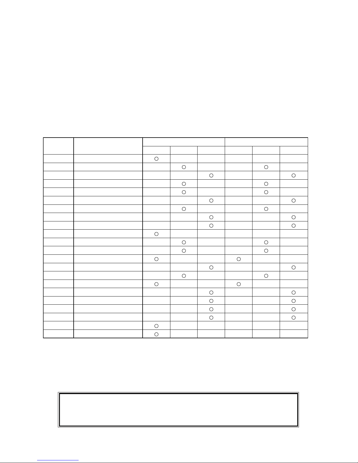
(1) Operations of functional items during cooling/heating
Cooling Heating
Dehumidify
Fan
Operation
Functional item
Thermostat
ON
Thermostat
ON
Thermostat
OFF
Thermostat
OFF
Hot start
(Defrost)
Compressor
4-way valve
Outdoor fan
Indoor fan
Louver motor
Drain pump
(4)
/
(2)
(2)
/
/
/
/
/
(2)
()
()
/
/
/
/
/
/
Thermostat ON:
Thermostat OFF:
(2)
Note (1) : Operation : Stop /: Turned ON/OFF by the control other than the room temperature control.
(2) ON during the drain motor delay control
(3) Drain pump ON setting may be selected by the indoor unit function setting of the wired remote controller.
(2) Dehumidifying operation
(a) When the humidity sensor is not provided (Models other than FDT Series)
return air thermistor [Th
I-A (by the remote controller when the remote control sensor is enabled)] controls the indoor
temperature environment simultaneously.
1)
Operation is started in the cooling mode. When the difference between the return air thermistor and the setting
temperature is 2°C or less, the indoor unit fan tap is brought down by one tap. That tap is retained for 3 minutes
after changing the indoor fan tap.
2) If the suction air temperature exceeds the setting temperature 3°C or more during defrosting operation, the indoor
fan tap is raised by one tap. That tap is retained for 3 minutes after changing the indoor fan tap.
3)
If the thermostat OFF is established during the above control, the indoor fan tap at the thermostat ON is retained so
far as the thermostat is turned OFF.
4)
After stopping the cooling operation, the indoor unit continues to run at Lo for 15 seconds.
(b) When the humidity sensor is provided (FDT Series only) [Optional]
1) Operation starts in the cooling mode, and the target relative humidity is determined based on the setting temperature.
If the humidity detected by the humidity sensor becomes lower than the target relative humidity, the indoor unit fan
tap is retained.
2)
Anything other than 1) above is same as the item (a) above.
(3) Timer operation
(a) Timer
Set the duration of time from the present to the time to turn off the air-conditioner.
It can be selected from 10 steps in the range from “OFF 1 hour later” to “OFF 10 hours later”. After the clock timer
setting, the remaining time is displayed with progress of time in the unit of hour.
(b)
OFF timer
Time to turn OFF the air-conditioner can be set in the unit of 10 minutes.
(c) ON timer
Time to turn ON the air-conditioner can be set. Indoor temperature can be set simultaneously.
(d) Weekly timer
Timer operation (ON timer, OFF timer) can be set up to 4 times a day for each weekday.
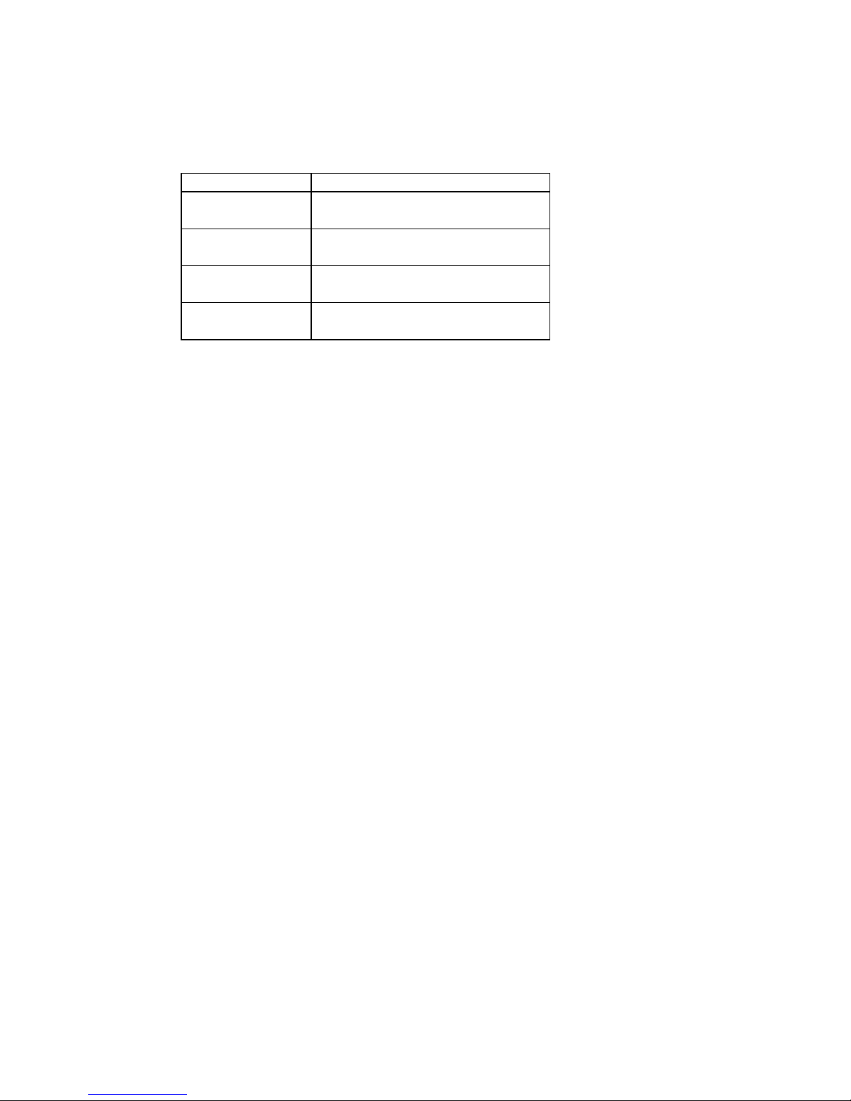
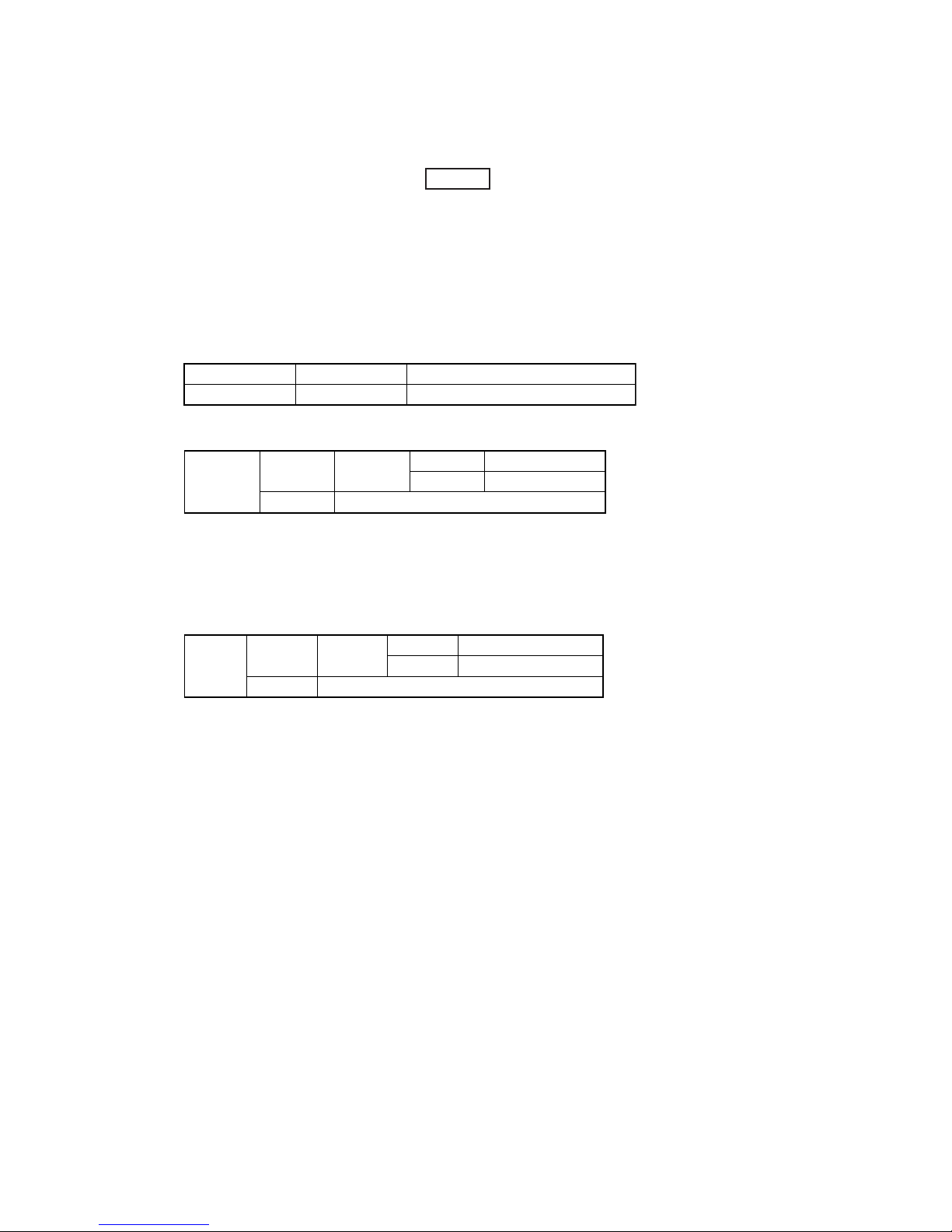
(e) Timer operations which can be set in combination
Timer
OFF timer
ON timer
Weekly timer
Timer
OFF timer
ON timer
Weekly timer
Note (1) : Allowed : Not
– 3 –
(4) Remote controller display during the operation stop
(a) “Centralized control ON” is displayed always on the LCD under the “Center/Remote” and “Center” modes during the
operation stop (Power ON). This is not displayed under the “Remote” mode.
(b)
If this display is not shown under the “Center/Remote” mode, check if the indoor unit power switch is turned on or not.
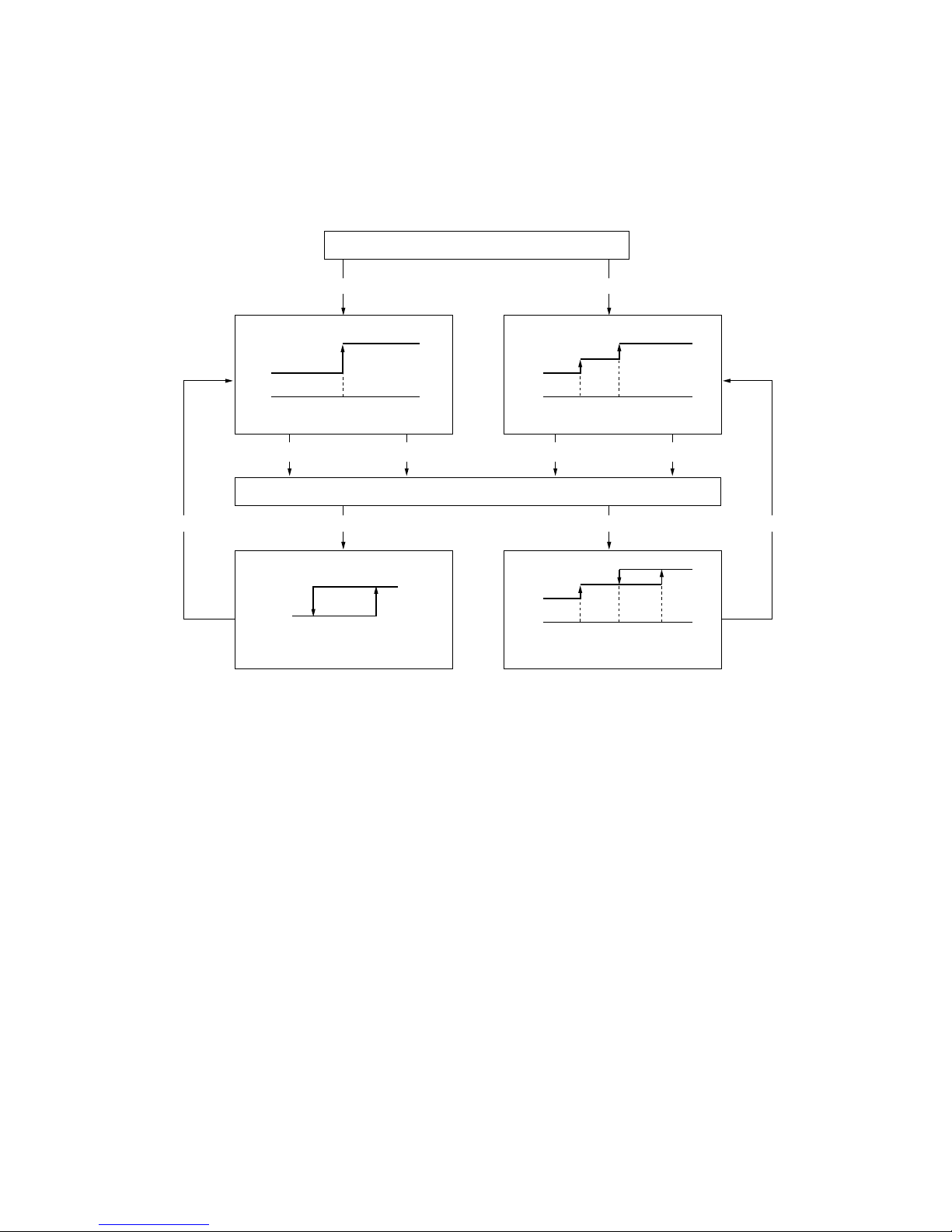
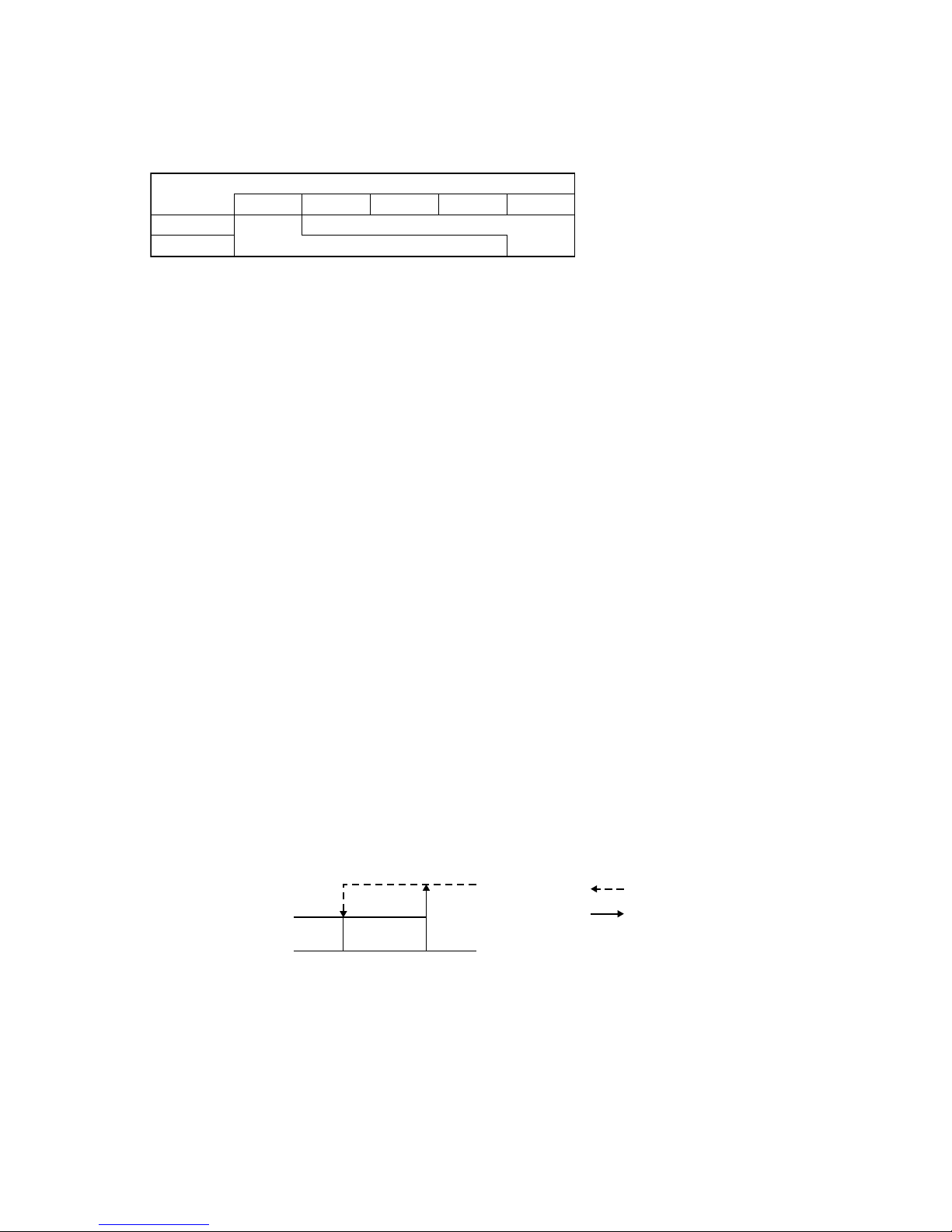
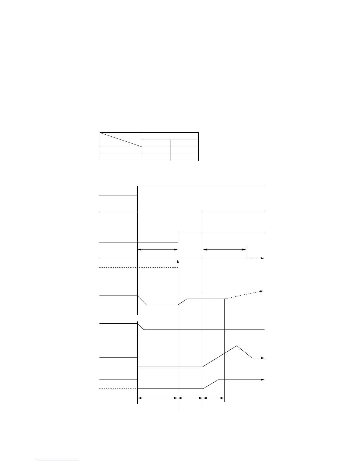
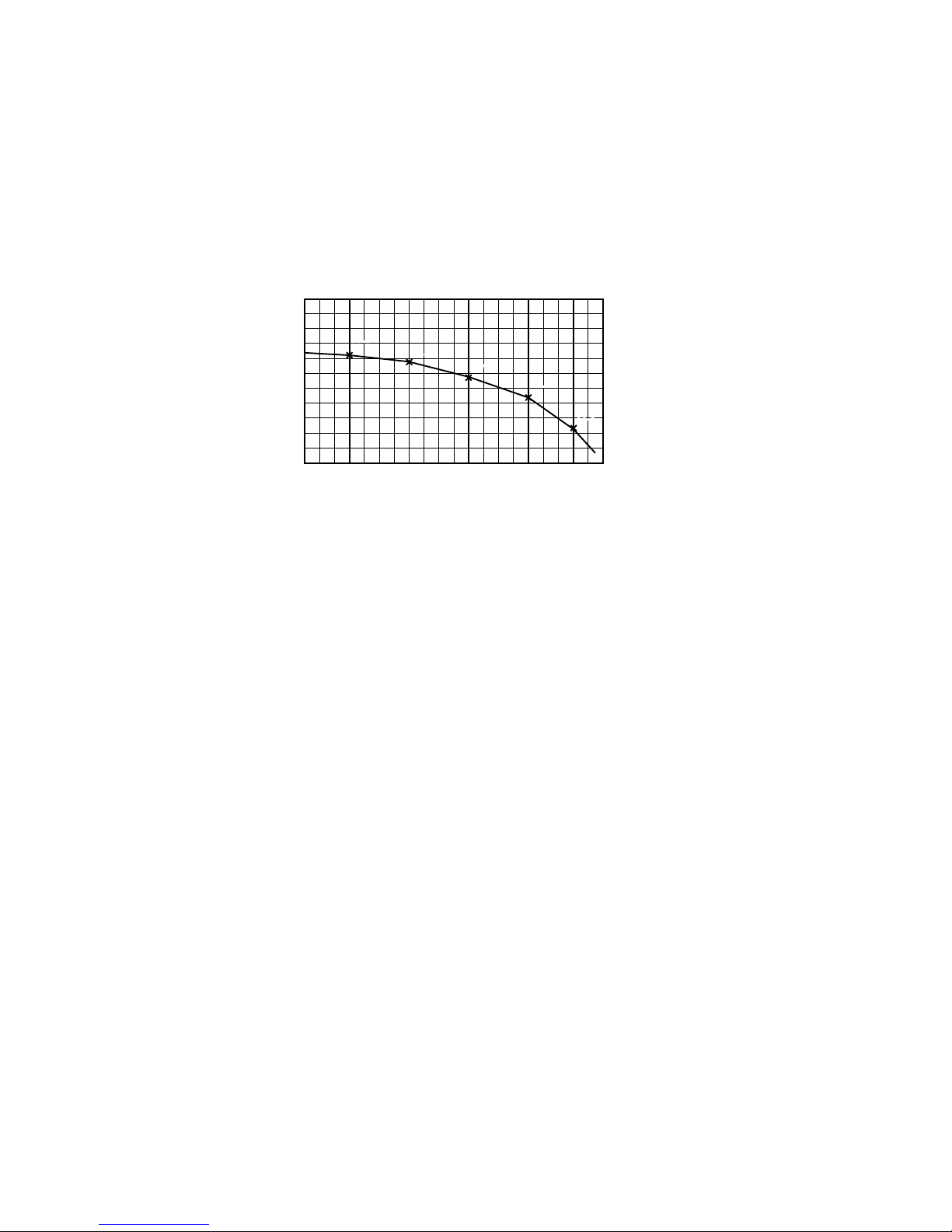
(5) Hot start (Prevention of cold draft during heating)
At the startup of heating operation, at resetting the thermostat, during defrosting operation and at returning to heating, the
indoor fan is controlled by the indoor heat exchanger temperature (detected with Th
I-R) to prevent the cold draft.
Judgment by heating start thermostat
Normal condition/Set airflow volume
Thermostat OFF Thermostat ON
Compressor OFFCompressor ON End of defrosting
Heat exchanger temp. 35˚C or higher, or after 7 minutes Heat exchanger temp. 35˚C or higher, or after 7 minutes
Defrosting start
Fan
Lo
Lo
Set airflow volume
Set airflow volume
Indoor heat exchanger temp. (˚C)
Indoor heat exchanger temp. (˚C)
35
35 45
25 35
Indoor heat exchanger temp. (˚C)
Set airflow volume
Fan
OFF
Lo
25 35
45
Set airflow volume
Fan
OFF
Indoor heat exchanger temp. (˚C)
Fan
Lo
(1)
Note (1) Heating preparation is displayed during the hot start (when the compressor is operating and the indoor fan does not provide the set airow volume).
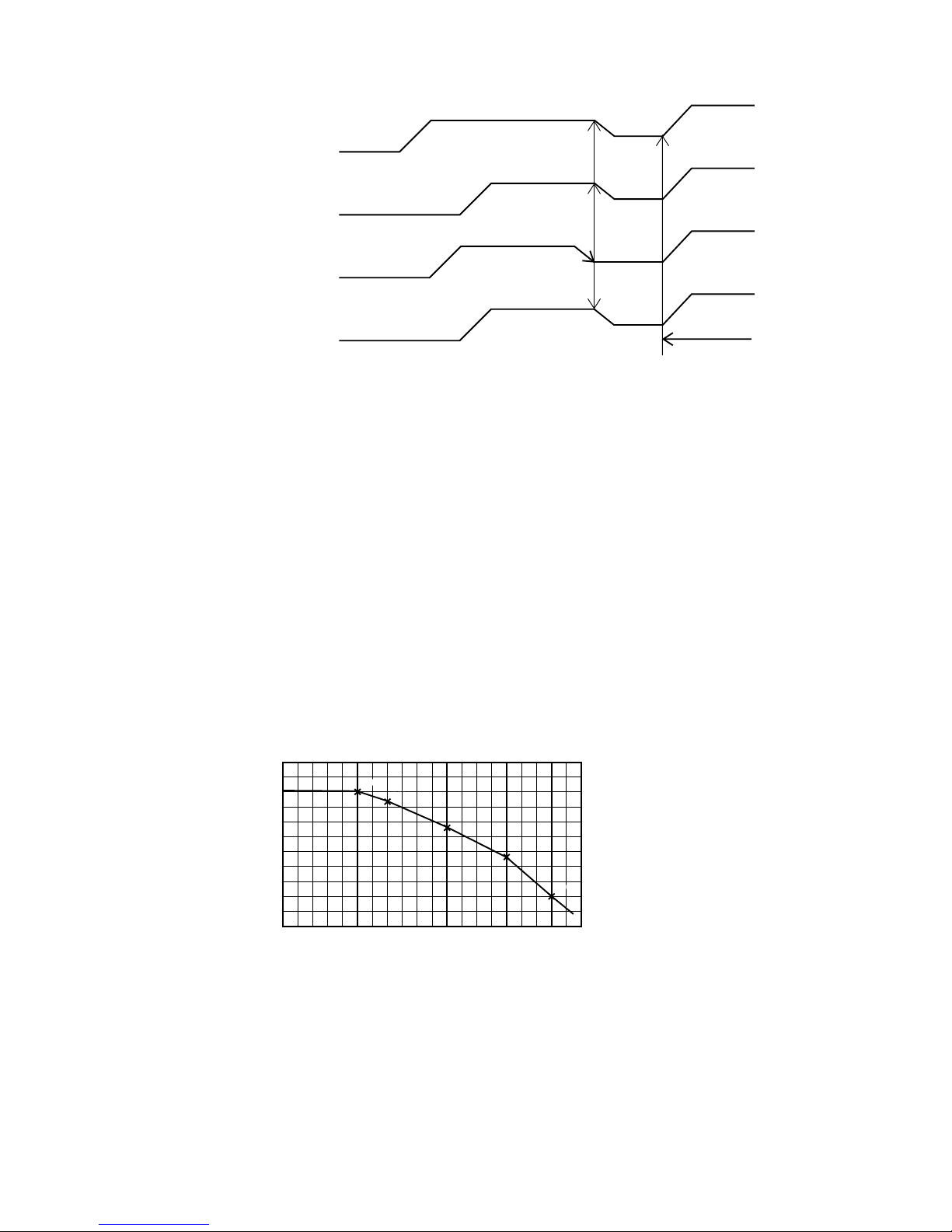
(6) Hot keep
Hot keep control is performed at the start of the defrost control.
(a)
Control
1) When the indoor heat exchanger temperature (detected with Th
I-R1 or R2) drops to 35°C or lower, indoor fan is
changed to the lower tap at each setting.
2)
During the hot keep operation, the louver horizontal control signal is transmitted.
(b) Ending condition
When the indoor fan is at the lower tap at each setting, it returns to the set airow volume as the indoor heat exchanger
temperature rises to 45°C or higher.
(7)
Fan control during the heating thermostat OFF
When the heating thermostat is turned OFF, the setting of the fan control is selectable with using the indoor function of wired
remote controller [Heating fan control].
(a)
Low speed (Factory default)
If the indoor heat exchanger temperature drops 35°C or lower with the heating thermostat OFF, the indoor fan operate at
the lower speed tap at each setting.
(b)
Set airow volume
Even if the indoor heat exchanger temperature drops 35°C or lower with the heating thermostat OFF, the indoor fan
continues to run at the set airow volume.
(c)
Intermittent operation
If the indoor heat exchanger temperature drops 35°C or lower with the heating thermostat OFF, the indoor fan operates at
the lower speed tap at each setting and, when the indoor heater exchanger temperature drops 25°C or lower, the indoor fan
stops for 5 minutes. Then the fan runs at the slow speed tap for 2 minutes, and the judgment is made by the thermostat.
(d)
Stop
If the indoor heat exchanger temperature drops 35°C or lower with the heating thermostat OFF, the indoor fan is turned
OFF. The same applies also when the remote controller sensor is effective.
– 4 –
(8) Filter sign
As the operation time (when ON/OFF switch is at ON) accumulates to 180 hours (1), “Filter cleaning” is displayed on the
remote controller. (This is also displayed when the unit is in trouble and under the centralized control, regardless of ON/OFF)
Note (1) Time setting for the lter sign can be made as shown below using the indoor function of wired remote controller “Filter sign setting”. (It is set at 1 at the
shipping from factory.)
Filter Sign Setting
Setting 1
Setting 2
Setting 3
Setting 4
Function
Setting time: 180 hrs (Factory default)
Setting time: 600 hrs
Setting time: 1,000 hrs
Setting time: 1,000 hrs (Unit stop)
(2)
(2)
After the setting time has elapsed, the “Filter cleaning” is displayed and, after operating for 24 hours further (counted also during the stop), the unit stops.
(9) Auto swing control [Applicable model: FDT, FDTC, FDTW, FDTS, FDTQ (Excepted duct panel model) FDK
and FDE]
(a)
Louver control
(i) Press the [Louver] button to operate the swing louver when the air conditioner is operating.
“Auto wind direction” is displayed for 3 seconds and then the swing louver moves up and down continuously.
(ii) To x the swing louver at a position, press one time the [Louver] button while the swing louver is moving so that
four stop positions are displayed one after another per second.
When
a desired stop position is displayed, press the [Louver] button again. The display stops, changes to show the
“Louver stop” for 5 seconds and then the swing louver stops.
(iii)
Louver operation at the power on
The louver swings one time automatically (without operating the remote controller) at the power on.
This allows inputting the louver motor (LM) position, which is necessary for the microcomputer to recognize the
louver position.
Note (1) If you press the Louver button, the swing motion is displayed on the louver position LCD for 10 second. The display changes to the “Auto wind
direction” display 3 seconds later.
(b) Automatic louver level setting during heating
While hot start operation and heating thermostat OFF operation, the louver keeps the level position (In order to prevent
the cold draft) whether the auto swing switch is operated or not (auto swing or louver stop), The louver position display
LCD continues to show the display which has been shown before entering this control.
(c)
Louver-free stop control
When the louver-free stop has been selected with the indoor function of wired remote controller “Louver control setting”,
the louver motor stops when it receives the stop signal from the remote controller. If the auto swing signal is received
from the remote controller, the auto swing will start from the position where it was before the stop.
Note (1) When the indoor function of wired remote controller “Louver control setting” has been switched, switch also the remote control function “Louver
control setting” in the same way.
(10) Compressor inching prevention control
(a) 3-minutes timer
When the compressor has been stopped by the thermostat, remote controller operation switch or anomalous condition, its
restart will be inhibited for 3 minutes. However, the 3-minute timer is invalidated at the power on.
(b)
3-minutes forced operation timer
• Compressor will not stop for 3 minutes after the compressor ON. However, it stops immediately when the thermostat is
turned OFF by the stop command by means of the ON/OFF switch or the change of operation mode.
•
If the thermostat is turned OFF during the forced compressor operation in heating mode, the louver position (with the
auto swing) is returned to the level position.
Note (1) The compressor stops when it has entered the protective control.
– 5 –
(11) Drain motor (DM) control [Applicable type: FDT, FDTC, FDTW, FDTS, FDTQ, FDUM, FDQS and FDU90~140]
(a) Drain motor (DM) start operation at the same time when compressor ON at cooling and dehumidifying mode and
keeps operating for 5 minutes after operation stop, the anomalous stop, thermostat OFF and switching from cooling or
dehumidifying operation to fan or heating operation.
Stop
(1)
Indoor unit operation mode
Control A
Control B
Compressor ON
Compressor OFF
Cooling
Dehumidifying
HeatingFan
(2)
Note (1) Including the stop from cooling, dehumidifying,
fan and heating operation and the anomalous stop.
(2) Including the “Fan” operation according to the
mismatch of operation modes.
(i) Control A
1) Ifthe oat switchdetectsany anomalousdrainingcondition, theunitstops withtheanomalous stop(displaysE9)
and the drain pump starts.
2)
Thedrainmotorkeepsoperatingwhiletheoatswitchisdetectingtheanomalouscondition.
(ii) Control B
Iftheoatswitchdetectsanyanomalousdraincondition,thedrainmotoristurnedONfor 5minutes,andat10 seconds
afterthe drainmotor OFFit checksthe oatswitch. Ifitisnormal,theunitisstoppedunderthenormalconditionor,if
thereisany anomalous condition, E9isdisplayedand the drain motoristurnedON. (The ON condition ismaintained
during the drain detection.)
(b)
Drain motor (DM) interlock control
(i) Start conditions
Depending on the function setting of the remote controller, the drain motor is turned ON under either one of the
following conditions.
1) During heating operation (Both the thermostat ON/OFF)
2) During heating operation (Both the thermostat ON/OFF) + Fan operation
3) Fan operation
(ii) Stop conditions
The drain motor is turned OFF 5 minutes after the stop of operatio
ns 1) to 3) above.
(12) Operation check/drain pump test run operation mode
(a) If the power is turned on when the dip switch (SW7-1) on the indoor PCB is ON state, it enters the mode of operation
check/drain pump test run. It is ineffective (prohibited) to change the switch after turning power on.
(b)
Whenthecommunicationwiththeremotecontrollerhasbeenestablishedwithin60secondsafterturningpoweronbythe
dip switch (SW7-1) ON, it enters the operation check mode. Unless the remote controller communication is established, it
enters the drain pump test run mode.
Note (1) To select the drain pump test run mode, disconnect the remote control connector (CNB) on the indoor PCB to shut down the remote controller
communication.
(c) Operation check mode
There is no communication with the outdoor unit but it allows performing operation in respective modes by operating the
remote controller.
(d) Drain pump test run mode
When
the drain pump test run is established, only the drain pump operates, and during operation the protective functions
by the microcomputer of indoor unit become ineffective.
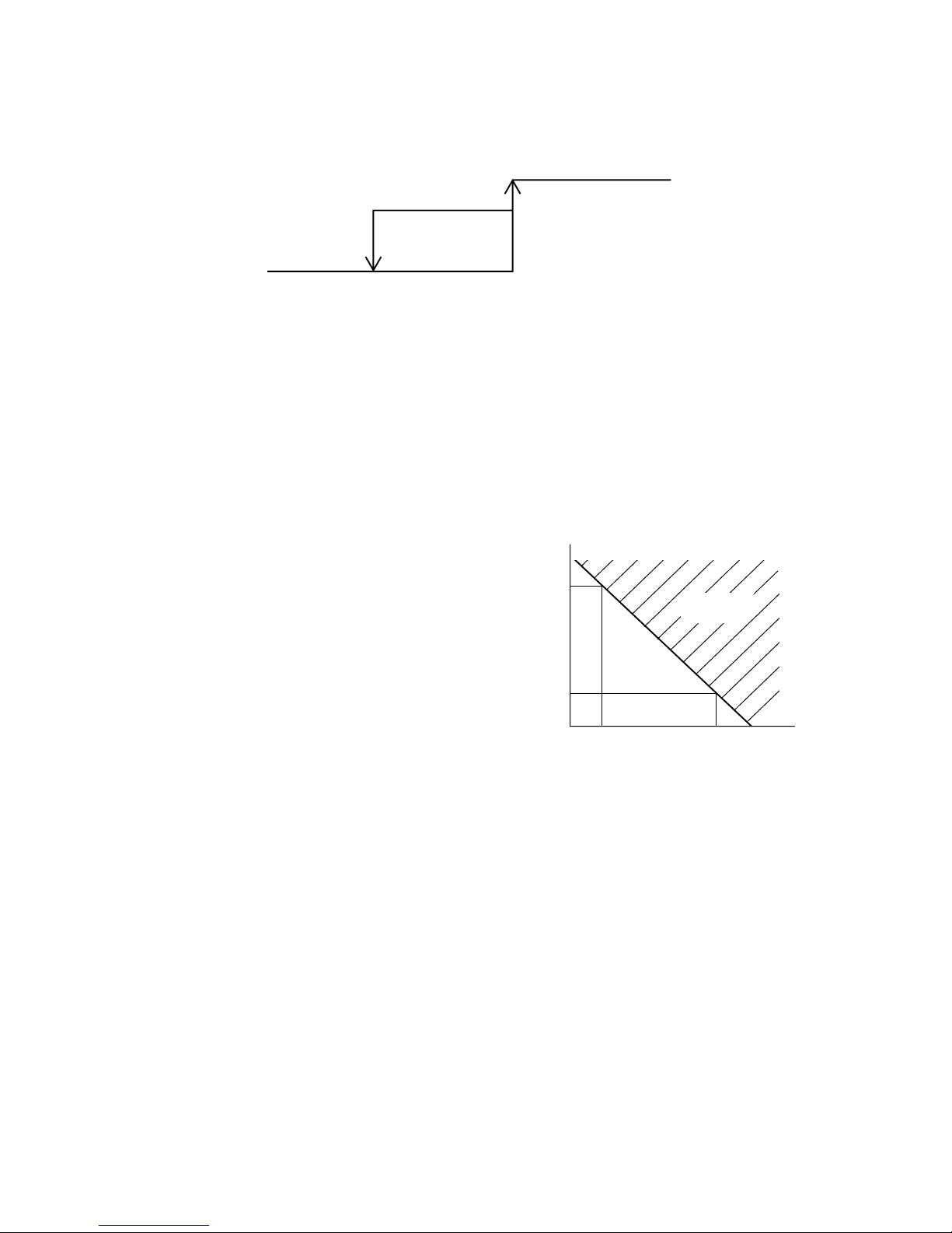
(13)
Indoor heat exchanger anti-frost (anti-frost control)
Thermostat OFF control
1) Thermostat is turned OFF depending on the temperature detected with the heat exchanger sensor (Th
I-R1, R2)
during “Cooling” and “Dehumidifying” operations.
1.0
Forced thermostat OFF
Thermostat ON OK
Heat exchanger temperature
5-min timer
Temperature drop
Temperature rising
10°C
2) For 4 minutes after the thermostat ON, the forced thermostat OFF control for the anti-frost protection is not effective.
a) When temperatures detected by the heat exchanger sensors Th
I-R1 and R2 are higher than the anti-frost protection
temperature at 4 minutes after the thermostat ON, the detection starts from the state of thermostat ON.
3) I
f the temperature detected with the heat exchanger sensor Th
I-R1 or R2 has stayed below the anti-frost protection
temperature(-0.5°C)continuously for5minutesafter 4minutesofthe thermostatONoperation,then thethermostatis
turned OFF forcibly.
The thermostat will be turned ON if temperatures detected by
Th
I-Ra and R2 picked up in the thermostat ON range.
4) “Anti-frost” signal is sent to the outdoor unit.
– 6 –
(14) Anomalous fan motor (FDT and FDK only)
Fan motor will be stopped with displaying “E16”, if it has detected the revolutions of 200 rpm or less continuously for 30
seconds at a rate of 4 times within 60 minutes, after starting the motor.
(15)
High ceiling control [Applicable type: FDT, FDTC, FDTW, FDTS and FDE]
When the indoor unit is installed at a high ceiling, the airow volume mode control can be changed with the indoor function of
wired remote controller “High ceiling setting”.
Setting Standard (Shipping) High Ceiling 1 High Ceiling 2
Remote controller setting Hi Me Lo Hi Me Lo Hi Me Lo
Fan speed Hi Me Lo UHi1
Hi Me UHi2 Hi Me
Note (1) It is set at Standard at the shipping from factory.
(2) At the hot start, heating thermostat OFF, or other, the indoor fan operate at the slow speed tap at each setting.
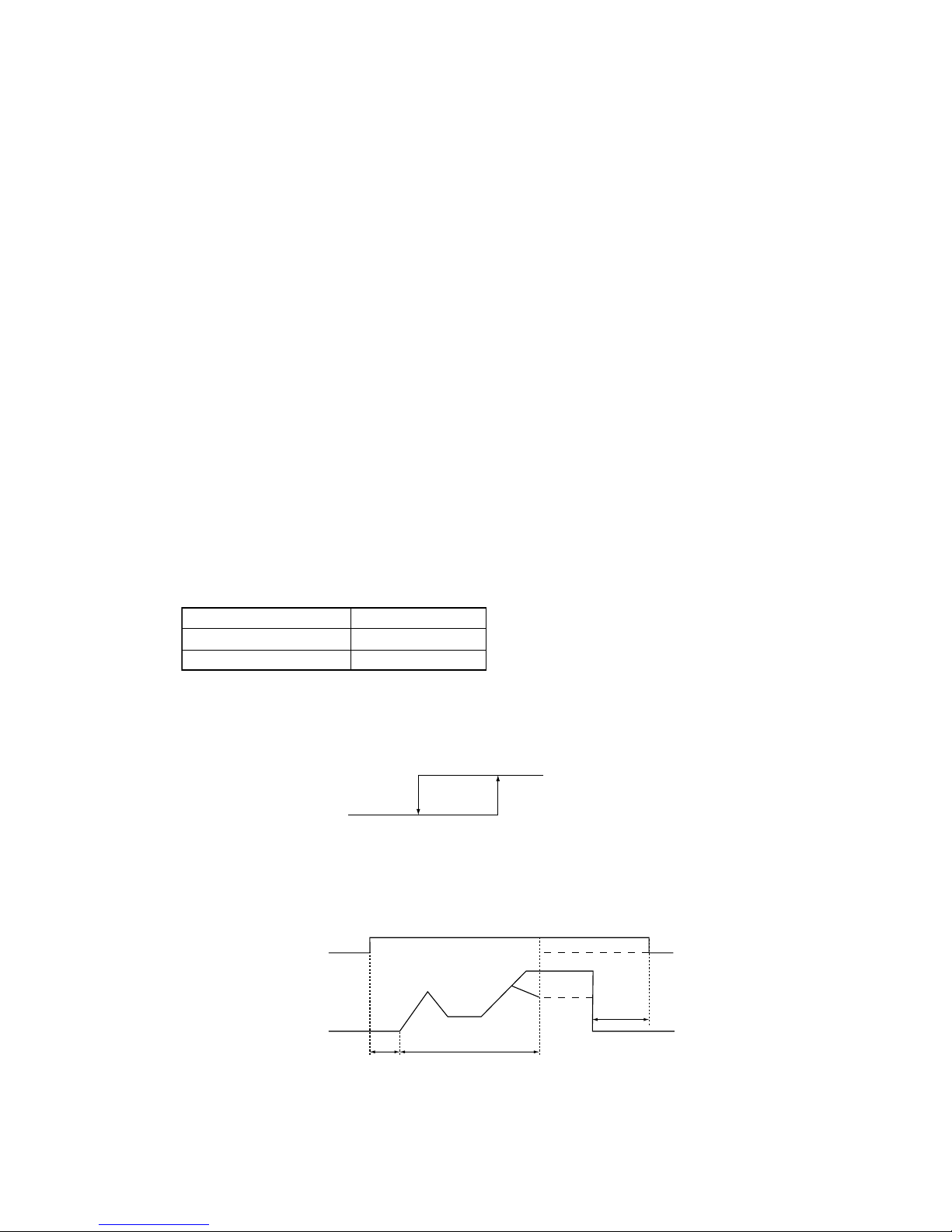
(16) Hot start
Indoor fan motor control is performed at the start of heating operation.
(a)
When the temperature detected with the indoor heat exchanger thermistor (Th
I-R1 or ThI-R2) drops 35°C or lower, it
control the fan with AC motor: Lo and DC motor: ULo.
(b)
When the heat exchanger thermistor detects 45°C or higher with the fan running at Lo/ULo, it returns to the set airow
volume.
Set airflow volume
Lo/ULo
35°C 45°C
Heat exchanger thermistor temp. (Th
I-R1 or R2)
(c) On the indoor unit of which the thermostat has been turned OFF during heating operation, the fan is turned OFF if the
heat exchanger thermistor temperature (Thi-R1 or Thi-R2) drops 25°C or lower.
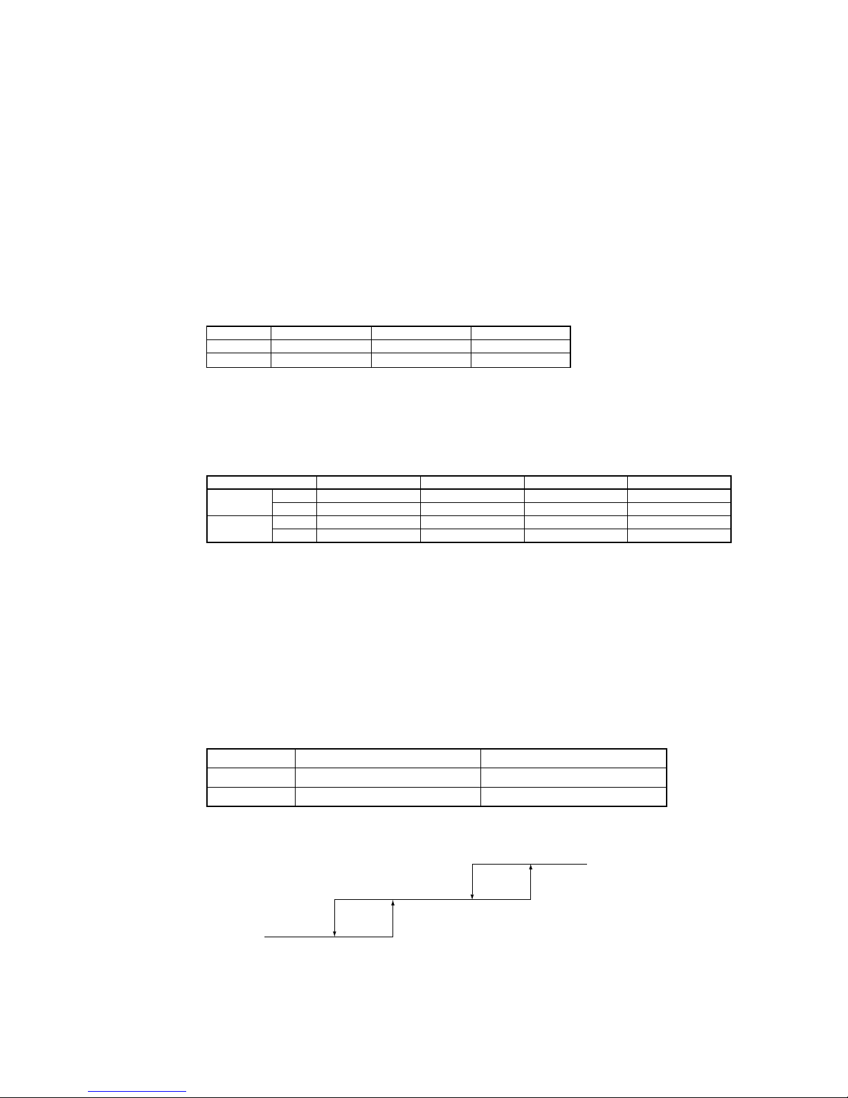
(17)
Detection room temperature compensation during heating
With the standard specication, the compressor is turned ON/OFF based on the setting temperature of thermostat. However,
when the thermostat OFF is likely to occur earlier because the unit is installed in a condition that warm air tends to accumulate
near the ceiling, the setting can be changed by using the indoor function of wired remote controller “Heating room temperature
compensation”. Since the compressor is turned ON/OF at one of the setting temperature at +3, +2 or +1°C, the feeling of
heating can be improved. However, the upper limit of setting temperature is 30°C.
Operation
Setting temperature
Room temp. (deg)
–1
+1
Stop
Standard
Compressor
Operation
Setting temperature
Room temp. (deg)
+4+2
Stop
With setting at +3°C
Compressor
(18) Return air temperature compensation
This is the function to compensate a difference between the detected temperature of the Return air thermistor and the measured
temperature after installation of unit.
(a)
It is adjustable in the unit of 0.5°C by using the indoor function of wired remote controller “Return air thermistor
compensation”.
• +1.0°C, +1.5°C and +2.0°C
• −1.0°C, −1.5°C and −2.0°C
(b) Since the compensated temperature is transmitted to the remote controller and the outdoor unit, it is controlled with the
compensated temperature.
Note (1) Compensation of detection temperature is effective for the indoor unit sensor only.
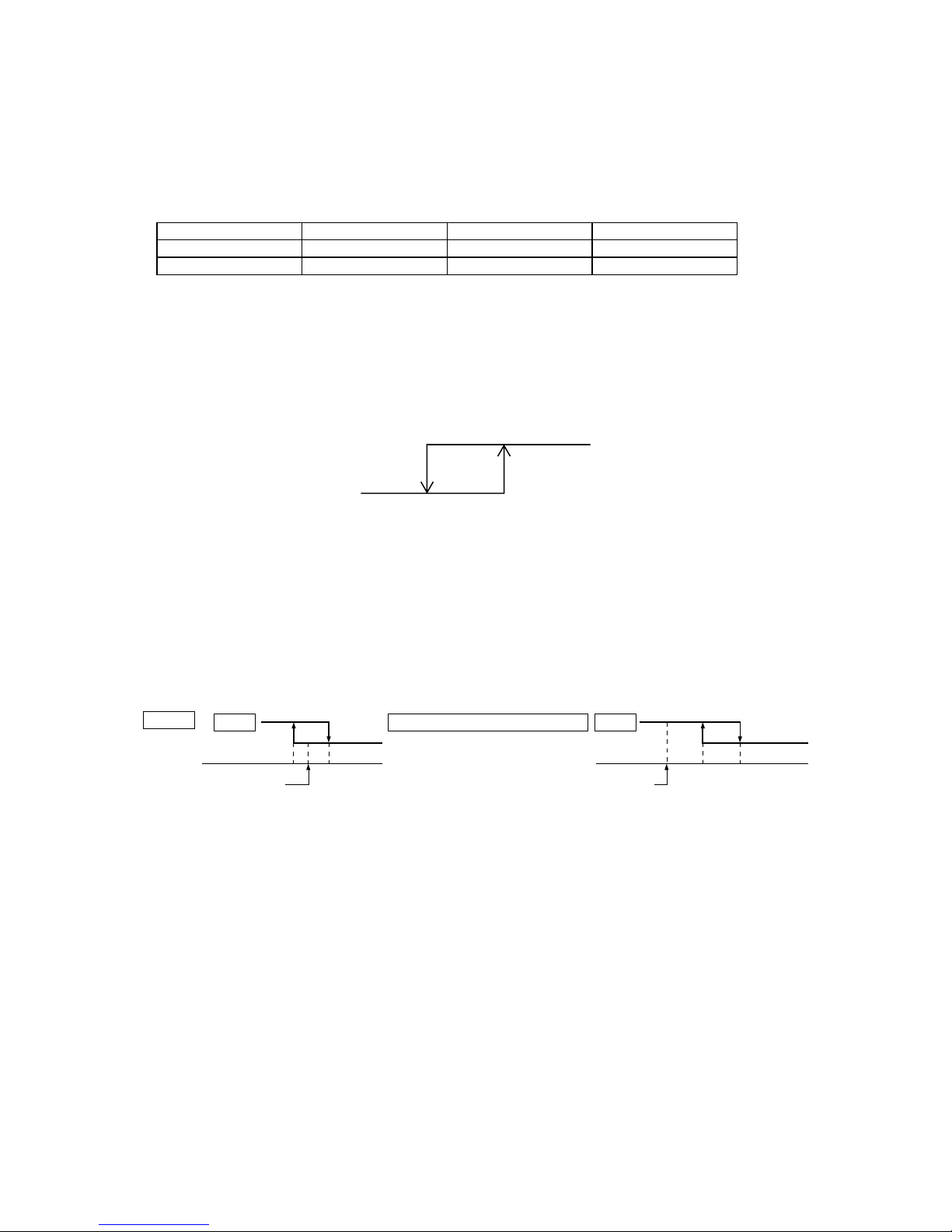
(19) External control (Remote display)/Remote operation
Always connect the wired remote controller. Otherwise, you cannot perform the remote operation.
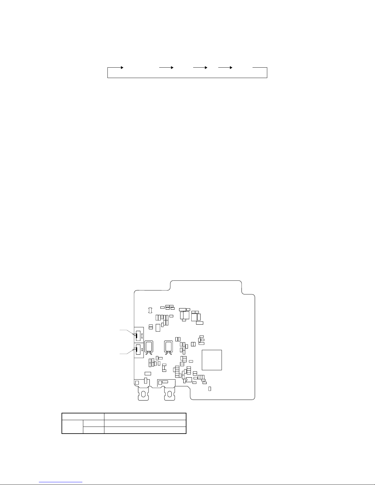
(a)
Output for external control (remote display)
(Optional remote RUN/STOP monitor kit can be utilized.)
Following
output connectors (CNT) are provided on the indoor control PCB. Connect the remote RUN/STOP monitor kit
and pick up respective dry contact signal.
•
Operation output
: Outputs DC12V relay drive signal during operation.
– 7 –
•
Heating output
: Outputs DC12V relay drive signal during heating operation.
•
Compressor ON output
: Outputs DC12V relay drive signal when the compressor is operating.
•
Error output
: When any anomalous condition occurs, it outputs DC12V relay drive signal.
(b)
Remote operation input
Remote operation inputs (switch input, timer input) connectors (CnT) are provided on the indoor control PCB.
However, the remote operation by the CnT is not effective when “Center mode” is selected with the air-conditioner.
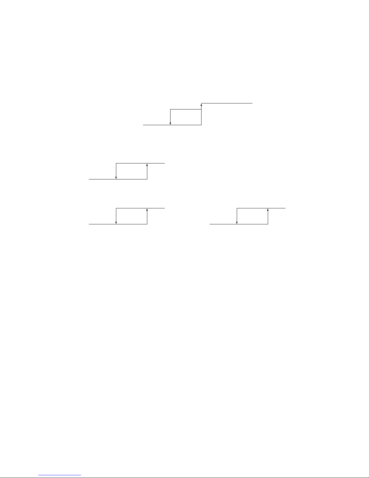
(i)
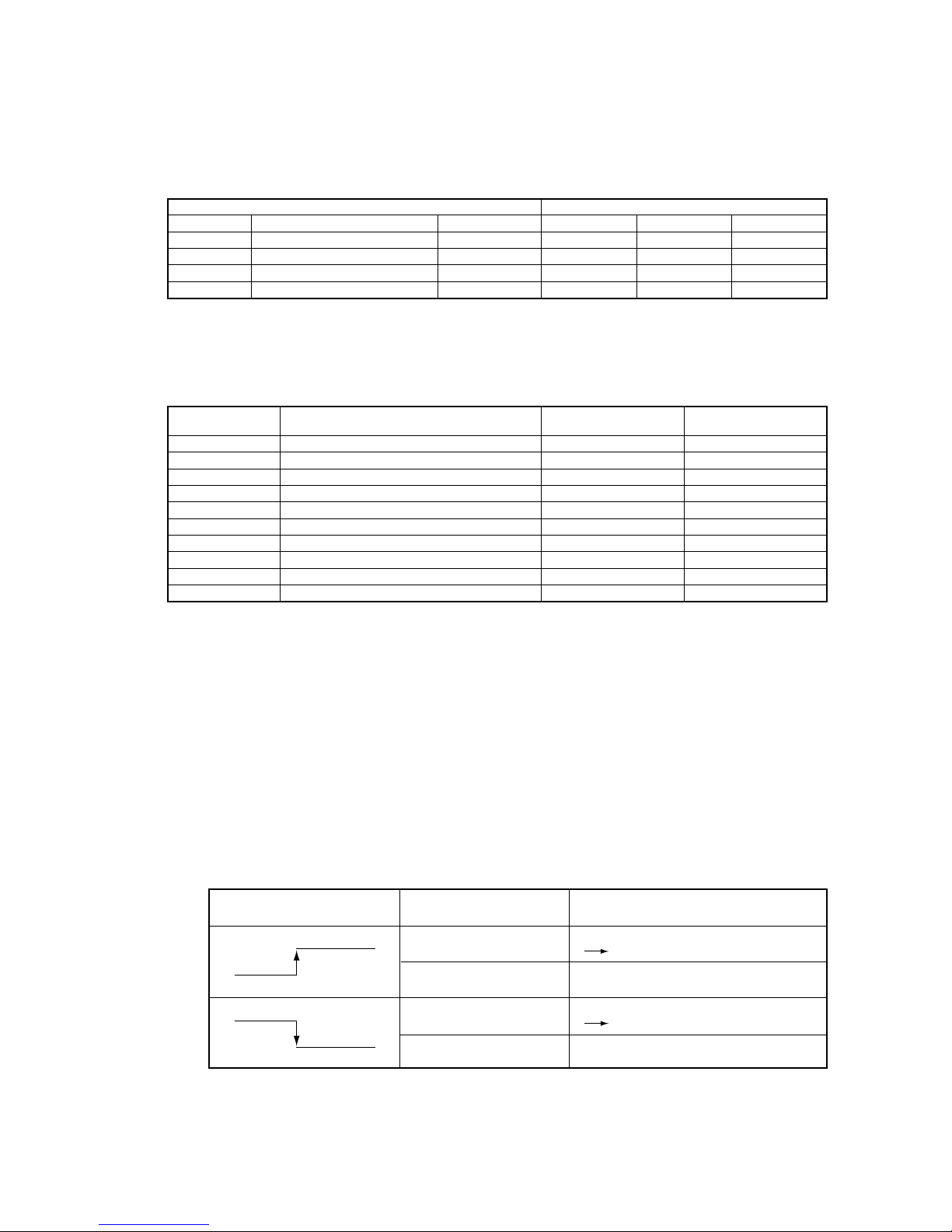
At the shipping from factory [Indoor function of wired remote controller “External input selector” is
set at the level input.]
• Startup at the input signal to CnT OFF ON [Edge input] … Air-conditioner ON
• Stop at the input signal to CnT ON OFF [Edge input] … Air-conditioner OFF
*ON
ONON
OFF OFF
OFF
OFF
OFF OFF
ONON
ONON
OFF
OFF
*ON
CnT input
Air-conditioner A
Air-conditioner B
(ii) When the setting is changed to the pulse input at site using the indoor unit function of wired
remote controller “External input selector”
It becomes effective only when the input signal to CnT is changed OFF
➝
ON and the air-conditioner operation [ON/
OFF] is inverted.
ON
ON
OFF
OFF OFF
OFF
ON
OFF
OFF
ON
ON
CnT input
Air-conditioner A
Air-conditioner B
(c) Processing of emergency stop signal
This emergency stop signal is used to stop all indoor unis connected to the same outdoor unit in emergency.
1) The emergency stop control becomes effective if the emergency stop control setting is changed to “Valid” from the
wired controller.
2)
If the emergency stop [E-63] signal is received from outdoor unit, it is transmitted to the remote controller and
makes stop.
(d)
Fresh air processing operation input
1) If indoor unit controller receive fresh air processing operation signal (*1) or fresh air processing stop signal from
remote controller, it output ON signal or OFF signal from CnD connector respectively.
*1.
Operation switch ON at interlock setting and ventilation switch ON at non-interlock setting.
2) Output relay is DC12V option and maximum relay load is LY2F (OMRON).
3)
In case of interlock setting, if either of indoor units connected to one remote controller is in the state of anomalous stop,
the fresh air processing unit connected to that indoor unit cannot be operated. Other processing units connected to the
indoor units operating normally can be operate.
I
n case of non-interlock setting, processing unit can start ventilation even though the connected indoor unit is in
anomalous stop.
4) In case of interlock setting if indoor unit stops, processing unit also stop.
5) In case of interlock setting if indoor unit stops with anomalous stop, processing unit also stop.
6) If indoor unit is started or stopped from center console, processing unit can start or stop in case of interlock setting,
but it keep stopping in case of non-interlock setting.
7)
Interlock or non-interlock can be set only on the remote controller.
(20) Dip switch function
Model capacity selection with SW6 0 : OFF, 1 : ON
Model P22 P28 P36 P45 P56 P71 P80 P90 P112 P140 P160 P224 P280
SW6-1 0 1 0 0 0 0 1 0 1 0 1 0 1
SW6-2 0 0 1 0 1 0 0 1 1 0 0 1 1
SW6-3 0 0 0 1 1 0 0 0 0 1 1 1 1
SW6-4 0 0 0 0 0 1 1 1 1 1 1 1 1
Note (1) ON marked with * means ON by a remote
controller switch or other.
– 8 –
1.3 Operation control function by the remote controller
(1) Switching sequence of the operation mode switches of remote controller
Dehumidifying
Cooling Fan Heating
(2) [CPU reset]
When the “CHECK” and “GRILL” buttons on the remote controller are pressed at the same time, this function is activated.
This function is same as power supply reset.
(3)
[Power failure compensation function]
• This function becomes effective when “POWER FAILURE COMPENSATION SET” is valid by setting the remote controller
functions.
•
The remote controller's status is always stored in memory, and after recovery of power, operation is resumed according to
the memory contents. However the auto swing stop position and timer mode are cancelled, but the weekly timer setting is
restored with the holiday setting through all weekdays.
By resetting the clock and cancelling the holiday setting for each weekday after recovery of power, weekly timer setting
becomes effective.
•
Contents stored in memory for power failure compenstion are as follows.
Note (1) Item
➅➆
and ➇ are stored in memory regardless of whether the power failure compensation setting is valid or invalid, and silent mode setting is
cancelled regardless of whether the power failure compensation setting is valid or invalid.
➀
Running or Stopping status just before power failure
If it had been operating under OFF timer mode or simple timer mode, memorzed status is as stopping (At the
recovery of power, the timer mode is cancelled but weekly timer setting is changed to the holiday setting through all
weekdays
➁
Operation mode
➂
Fan speed mode
➃
Room temperature setting
➄
Louver auto swing/stop
However
, the stop position (position 4) is cancelled and is becomes the level position (position 1).
➅
“Remote
control function items”, set with the remote controller function setting (“Indoor unit function items” are
stored in the inoor unit's memory.)
➆
Upper limit value and lower limit value set by temperature setting control.
➇
Clock timer setting and weekly timer setting (Other timer settings are not sotred in memory).
[Parts layout on remote controller PCB]
X Y
SW2
SW1
A
B
M
S
親
子
SW1
SW2
Control selector switch (SW1)
Switch Function
SW1
M
Master remote controller
S
Slave remote controller
Note (1) SW2 is not normally used, so do not change the selection.
-
9
-
1.4 Operation control function by the outdoor controller
(A) Normal control
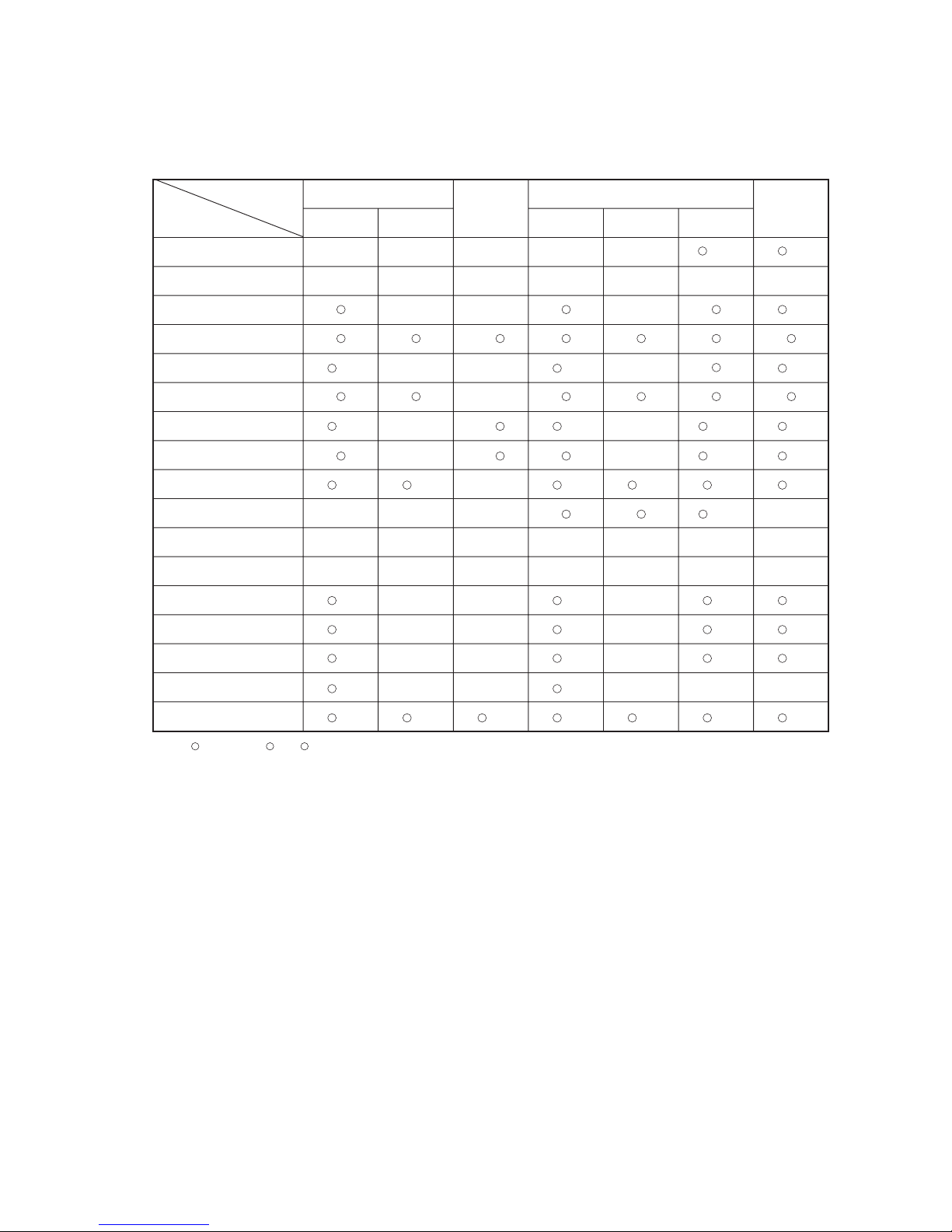
(1) Operation of major functional components under each operation mode
Functional
Components
Indoor unit fan
Compressor [CM1]
Compressor [CM2]
Outdoor unit fan [FMo-1]
Outdoor unit fan [FMo-2]
4 way valve [20S]
Solenoid valve [SV6] [SV7]
Solenoid valve [SV13]
Electronic expansion valve
for heating [EEVH1, 2]
Electronic expansion valve
for sub-cooling [EEVSC]
Indoor unit electronic
expansion valve
Operation
mode
Cooling Heating
Defrost
Thermostat OFFThermostat ONThermostat OFFThermostat ON
Fan
Dehumidify
Remote controller
command
Overheating
control response
Outlet temperature
control response
Overheating
Control Response
Fully open Fully closed
Slight opening
control
Model-specific
aperture opening
angle
Fully open
※1
※3
Fully open
※3※4
Fully closed※2Fully closed Fully closed Fully closed Fully closed
※2
Overheating
control response
Opening angle
control
Fully closed
/ Fully open
Opening angle
control
Remote controller
command
Remote controller
command
Remote controller
command
Intermittent
operation
→ /
/
/
/
→
→
→
/
/ /
/
/
/
/
Inverter cooling fan
[FMC1, 2]
/ / / / / /
/
/
/
/
/
/
Crankcase heater [CH1,2]
/ / / / / / /
Magnetic contactor CM1
[52X1]
/
Magnetic contactor CM2
[52X2]
Solenoid valve [SV1]
/ / / /
Solenoid valve [SV2]
/ / / /
Notes(1) : ON, : OFF, /, /: ON or OFF
(2) ※1: The EEVH1, 2 of master unit are fully opened and those of slave unit are fully closed.
(3) ※2: When the unit is stopped from cooling operation, the EEVH1, 2 of master unit are fully opened and those of slave unit are fully closed.
When the unit is stopped from heating operation, the EEVH1, 2 of both master and slave units are fully closed unless the opening degree is specified
by the low pressure protective control.
(4) ※3: When the operation mode is changed from heating to cooling/dehumidifying, EEVH1, 2 are maintained at fully closed position and EEV of only one
indoor unit keeps 60 pulse until 20S is turned OFF.
(5) ※4: When the operation mode is changed from cooling/dehumidifying to heating, EEVH1, 2 are maintained at fully opened position and EEVs of all
indoor units keep 0 pulse until 20S is turned ON.
(6) This shows the state of output when all indoor units are in the same operation mode.
-
10
-
(2) Compressor control (Master unit/slave unit)
(a) Starting compressor
(i) Compressor starting order (2 compressors specification)
After turning the power on, rstly CM1 compressor starts. (In case of the combination use, it is CM01 of master
unit) And corresponding to the condition of under-dome temperature and to the required capacity of indoor units
thermostat ON, the next compressor will start sequentially, and nally maximum 4 compressors ( in case of combi-
nation use) will start simultaneously.
1)
Single use
The range of frequency for each compressor corresponding to the heat load is shown in below mentioned table.
(The table shows the case that CM1 starts rst. If CM2 starts rst, the frequency of CM2 should be applied that
of CM1 shown in heat load zone 1 instead.)
Following tabel is shown the case that the maximum compressor frequency is 120Hz.
Note (1) Value in ( ) are for the models FDC615, 680KXE6
2) Combination use
The range of frequency for each compressor corresponding to the heat load is shown in below mentioned
table. (The table shows the case that CM01 starts rst. If CM11 starts rst, the frequency of CM11 should be
applied that of CM01 shown in heat load zone 1 instead.)
Note (1) Value in ( ) are for the models FDC1180~1360KXE6
(ii) Rotation of compressor start/stop order
1) The compressors will be changed over by determinating the start/stop order in each heat load zone.
2) In case of single use, the starting order of CM1 and CM2 will be changed over on each occasion when the out-
door unit stops.
3)
In case of combination use, the starting order of CM01(CM11) and CM02(CM12) will be changed over on each
occation when the master unit or slave unit stops all independently.
4)
In case of combination use, the starting order of master and slave units will be changed over on each occasion
when the master unit or slave unit stops all independently.
Starting order of outdoor units
Master→Slave→Master
(Reference)
Change in number of compressors operating
Note (1) Value in ( ) are for the models FDC615, 680KXE6 and FDC1180~1360KXE6
(2) After recovery of power blackout, starting order of compressor is always CM01of master unit.
Model
FDC335
~
680
FDC735~1360
Starting Order of Outdoor Units Starting Order of Compressors
CM 1 → CM 2 → CM 1
Master → Slave → Master CM 1 → CM 2 → CM 1
−
CM1
Heat load zone
CM2
0
0Hz
0Hz
1
20~112Hz (22~92Hz)
0Hz
2
42 (34)~120Hz
42 (34)~120Hz
Heat load zone
Master unit
Slave unit
CM01
CM02
CM11
CM12
0
0Hz
0Hz
0Hz
0Hz
1
20~112Hz (20~92Hz)
0Hz
0Hz
0Hz
2
42~112Hz (34~92Hz)
0Hz
42~112Hz (34~92Hz)
0Hz
3
42~120Hz (34~120Hz)
42~120Hz (34~120Hz)
42~120Hz (34~120Hz)
42~120Hz (34~120Hz)
1-Compressor
2-compressors
4-compressors
80Hz
(60Hz)
112Hz
(92Hz)
80Hz × 2
(66Hz × 2)
112Hz × 2
(92Hz × 2)

-
11
-
(3) Starting control of the compressor (Master unit/Slave unit)
According to the elapsed time after power ON and to the number of start-up, the starting control method of compressor is
shown in following table. However during the defrost control, oil return control and oil equalization control, the starting control
method of compressor is depended on that of the each control.
(a)
4-way valve switching safeguard (Master unit/Slave unit)
At starting, the inverter compressor (CM1, CM2) is operated under following conditions regardless of the decision frequency.
(i)
0-20Hz operation
It is operated in the range of 0-20Hz. However during this operation, the compressor protective controls like current safe
control, high pressure control, discharge pipe temperature control, low pressure control, power transistor temperature control,
under-dome temperature control and compression ratio protective control are not performed.
(ii)
25-40(48)Hz opearation
The maximum frequency is determined by the temperature detected with the outdoor air temperature thermistor (Tho-A).
1)
In case of 0°C or lower of Tho-A: It starts to increase the frequency up to 48Hz as maximum frequency and
when the frequency reaches 48Hz, it stops.
2)
In case of higher than 0°C of Tho-A: It starts to increase the frequency up to 40Hz as maximum frequency and.
when the frequency reaches 40Hz, it stops. However during this operation, if the starting conditions of the com-
pressor protective controls like current safe control, high pressure control, discharge pipe temperature control,
low pressure control, power transistor temperature control, under-dome temperature control or compression ratio
protective control is satised, this control ends and it is controlled according to such protective control satised
with. And if the compressor frequency is determined and this protective control is cancelled, it returns to the nor-
mal operation.
(b)
Compressor protective start control (Master unit/Slave unit)
The compressor frequency is controlled regardless of the target frequency.
1)
Up to 1minutes 45 seconds after the compressor starts, it is operated at 20Hz.
2) When 1minutes 45 seconds has elapsed after the compressor starts, it is operated at the frequency by compressor
potective start control.
(c)
Compressor protective start control "A" according to the crankcase heater ON time (Master unit/Slave
unit)
If it is the 1st startup after 45 minutes of the cumulative crankcase heater ON time has elapsed since power ON or if it is
the subsequent startup after the compressor has stopped for 45 minutes or more since power ON, it starts operation accord-
ing to this control.
1)
After 4-way valve switching safeguard, inverter frequency is set at 20Hz. And during reducing frequency to 20Hz
after 4-way valve switching safeguard, if the time for reaching to 20Hz is elasped 1 minutes after startup, it is set at
the maximum frequency after 1 minute elasped (20Hz+5Hz).
2)
During the period of 15 minutes after the inverter frequency reaches to 10Hz (the frequency to complete startup), the
maximum inverter frequency will be increased from 20Hz by 5Hz per minute.
3)
If the compressor stops within the period of 15 minutes after startup, and when the compressor starts again, the maxi-
mum inverter frequency is increased from 20Hz by 5Hz per minute during the cumlative period of 15 minutes under
this control after the initial startup.
Conditions Starting method
① The 1st startup after 45minutes or more has elapsed since
power ON, or the subsequent startup after the
compressor has been stopping for 45 minutes or longer
with keeping the power ON.
After 4-way valve switching safeguard, "compressor
protective start control A" will be perfomed according to the
crankcase heater ON time. (See followings)
② The 1st startup after less than 45 minutes has elasped
since power ON
After 4-way valve switching safeguard, "compressor
protective start control B" will be perfomed according to the
crankcase heater ON time. (See next page)
③ The startup other than ① and ② mentioned above.
After 4-way valve switching safeguard, "compressor
protective start controls" will be perfomed.
-
12
-
4) When the under-dome temperature (detected by Tho-C) exceeds 20°C and the under-dome superheat is 15degC, the
compressor protective start control "A" is cancelled and the inverter frequency will be increased by 5Hz per 25 seconds.
(d)
Compressor protective start control "B" according to the crankcase heater ON time (Master unit/Slave
unit)
If it is the 1st startup after the cumulative crankcase heater ON time has elapsed less than 45 minutes since power ON
1) After 4-way valve switching safeguard, inverter frequency is set at 20Hz. And during reducing frequency to 20Hz
after 4-way valve switching safeguard, if the time for reaching to 20Hz is elasped 1 minutes after startup, it is set at
the maximum frequency after 1 minute elasped (20Hz).
2) During the period of 18 minutes after the inverter frequency reaches to 10Hz (the frequency to complete startup op-
eration), the maximum inverter frequency will be increased from 20Hz by 5Hz per 2 minute.
3)
From 18 minutes to 24 minutes after startup, the maximum inverter frequency will be increased by 5Hz per 1 minute,
and this control will end when 24 minutes is elapsed after startup.
4)
After this control ends once, if it is the 2nd startup or the period of 45 minutes after th power ON is elapsed, this con-
trol will be shifted to the compressor protective start control "A".
5)
If the compressor stops within 24 minutes after startup, and when the compressor starts again, the compressor protective
start control "B" is performed during the cumlative period of 24 minutes after the initial startup. However when the period
of 45 minutes has elapsed since compressor stopped, the control is shifted to the compressor protective start control "A".
6) When the under-dome temperature (detected by Tho-C) exceeds 20°C and the under-dome superheat is 15degC, the
compressor protective start control "B" is cancelled and the inverter frequency will be increased by 5Hz per 25 sec-
onds.
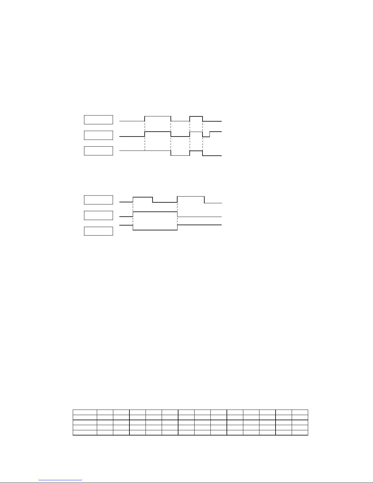
(4) Solenoid valve (SV6,7) control for oil return from oil separator (Maste unit/Slave unit)
(a) When the compressor starts, the following solenoid valve for corresponding compressor is opened respectively.
(b) SV6, SV7 is kept open for the period of 3 minutes after 4-way valve switching safeguard control and compressor protective
control start.
(c)
If the compressor frequency is 80Hz (68Hz) or higher, SV6,7 opens, and if the compressor frequency is 76Hz(64Hz) or
lower, it closes.
Note (1) Value in ( ) are for the models FDC615, 680KXE6 and FDC1180~1360KXE6
(d) If the compressor stops after SV6, 7 opens, SV6, 7 remains open for 3 minutes and 10 seconds, then closes.
76Hz
(64Hz)
80Hz
(68Hz)
Actual compressor frequency (Hz)
SV6, 7 open
SV6, 7 closed
Run
command
OFF
Stop
3 minutes
15 sec.
OFF
Stop
76Hz or
lower
80Hz or higher
3 minutes
10 seconds
Solenoid valve
(SV6, 7)
Compressor
ON
20Hz
Compressor
Starts
Compressor
CM1
CM2
Solenoid valve
SV6
SV7
-
13
-
(5) Outdoor fan control (Master unit/slave unit)
(a) DC fan motor control
The outdoor fan is controlled from 0th speed to 4th speed, and set the standard speed according to the model and operation
mode.
Under normal condition, 1st speed and 4th speed is standard, and under each condition the stepless fan control between 1st
speed and 4th speed is performed.
(b)
Outdoor fan speed and fan motor rotation speed
(c) At the unit startup, outdoor fan is operated at 4th speed.
(d) DC fan motor startup control
①
When the outdoor fan starts after stopping, the startup fan control is performed by checking the fan speed.
②
If
the rotating direction of the stopping fan, either FMo1 or FMo2, is reverse and its speed is 700min
-1
or higher, the
both fans cannot be started.
③
If
the rotating direction of the stopping fans, both FMo1 and FMo2, are reverse but its speed is less than 700min
-1
for
3 seconds continuously, the fan can be started.
④
During the period of 5 seconds after 52C1 is turned ON, the outdoor DC fan is prohibited to start.
Fan tap
FDC335, 400
Cooling
FM
O
1
0th speed
1st speed
2nd speed
3rd speed
4th speed
0
0
0
160
960
FM
O
2
0
160
400
160
960
FM
O
1
0
0
0
160
960
FM
O
2
0
160
400
160
960
Heating
FDC450
Cooling
FM
O
1
0
0
0
160
1080
FM
O
2
0
160
400
160
1080
FM
O
1
0
0
0
160
1080
FM
O
2
0
160
400
160
1080
Stop
1-unit operation min. speed
1-unit operation max. speed
2-unit operation min. speed
2-unit operation max. speed
Heating Remarks
Unit: min
-1
Fan tap
0th speed
1st speed
2nd speed
3rd speed
4th speed
FDC504〜680
Cooling
FM
O1
0
0
0
160
1140
FM
O2
0
160
400
160
1140
FM
O1
0
0
0
160
1140
FM
O2
0
160
400
160
1140
Stop
1-unit operation min. speed
1-unit operation max. speed
2-unit operation min. speed
2-unit operation max. speed
Heating Remarks
Unit: min
-1
-
14
-
(6) Compressor pre-start control (Master unit/slave unit)
(a) The following control is performed when the compressor ON conditions are established.
(i) Pre-start control when the operation mode is same as previous operation mode:
1) In case of "Cooling /Dehumidifying" mode, 4-way valve is turned OFF. In case of "Heating" mode, 4-way
valve
is turned ON.
However
if the operation mode is same as previous operation mode and 4-way valve is retaing prescribed condi-
tion, the control status of 4-way valve is unchanged.
2)
Solenoide valve SV6 and SV7 are turned ON.
3) The opening degree of EEVH1, 2 for heating and EEVSC for subcooling coil are set to the initial opening degree
mentioned in following table. The expansion valves EEVH1, 2 are operated rst, and after those operations are
completed, the expansion valve EEVSC will be operated.
Note (1) Expansion valves of master unit and slave unit are operated respectively.
4) Fan motors FMo1, FMo2 and compressor start 15 seconds after the compressor ON conditions are satised.
Cooling Heating
Heating
Cooling
FM
O
1,2
OFF
OFF
ON
ON
ON
20S
SV6
EEVH1,2 470
EEVSC
CM1 ON
CM2 ON
3 minutes
3 minutes
Open/close control
Opening degree control
Initial opening degree
Full-close or 100
pulse
Opening degree control
Full-close
OFF
OFF
Min. of 3 minutes 15 seconds 6 seconds
Compressor stop Compressor start
Starting conditions are satisfied
Operation mode
Cooling
EEVH1, 2
EEVSC
Name
Item
470
32
10
0
(Unit: Pulse)
Heating

-
15
-
(7) Crankcase heater control (Master unit/Slave unit)
(a) Crankcase heater ON (power on) and OFF (power off) are controlled with the under-dome temperature thermistor.
(b) Crankcase heater CH1 is turned ON, when the under-dome temperture (Tho-C1)
<
=
(SST)+20°C
(c)
Crankcase heater CH1 is turned OFF, when the under-dome temperture (Tho-C1)
<
=
(SST)+25°C
(d)
Crankcase heater CH2 is turned ON, when the under-dome temperture (Tho-C2)
<
=
(SST)+20°C
(e)
Crankcase heater CH2 is turned OFF, when the under-dome temperture (Tho-C2)
<
=
(SST)+25°C
(Note) SST: Low pressure saturated temperature detected with low pressure sensor (LPS)
(f) Crankcase heater CH1 is turned OFF, when the under-dome temperature (Tho-C1)
<
=
-
40°C and CM1 is ON
(g) Crankcase heater CH2 is turned OFF, when the under-dome temperature (Tho-C2)
<
=
-
40°C and CM2 is ON
(Note) (f) and (g) are the protection for thermistor (Tho-C1, -C2) breakage
Heating Cooling
Cooling
Heating
FMo1,2
OFF
OFF
ON
20S
SV6
EEVH1,2
EEVSC
CM1
CM2
ON
ON
ON
3 minutes
3 minutes
Open/close control
Initial opening degree
Full-close
Opening
degree control
Opening
degree control
Full-open
OFF
OFF
15 sec. 1 minute 45 secondsMin. of 3 minutes
Compressor stop
Compressor start
Starting conditions are satisfied
-
16
-
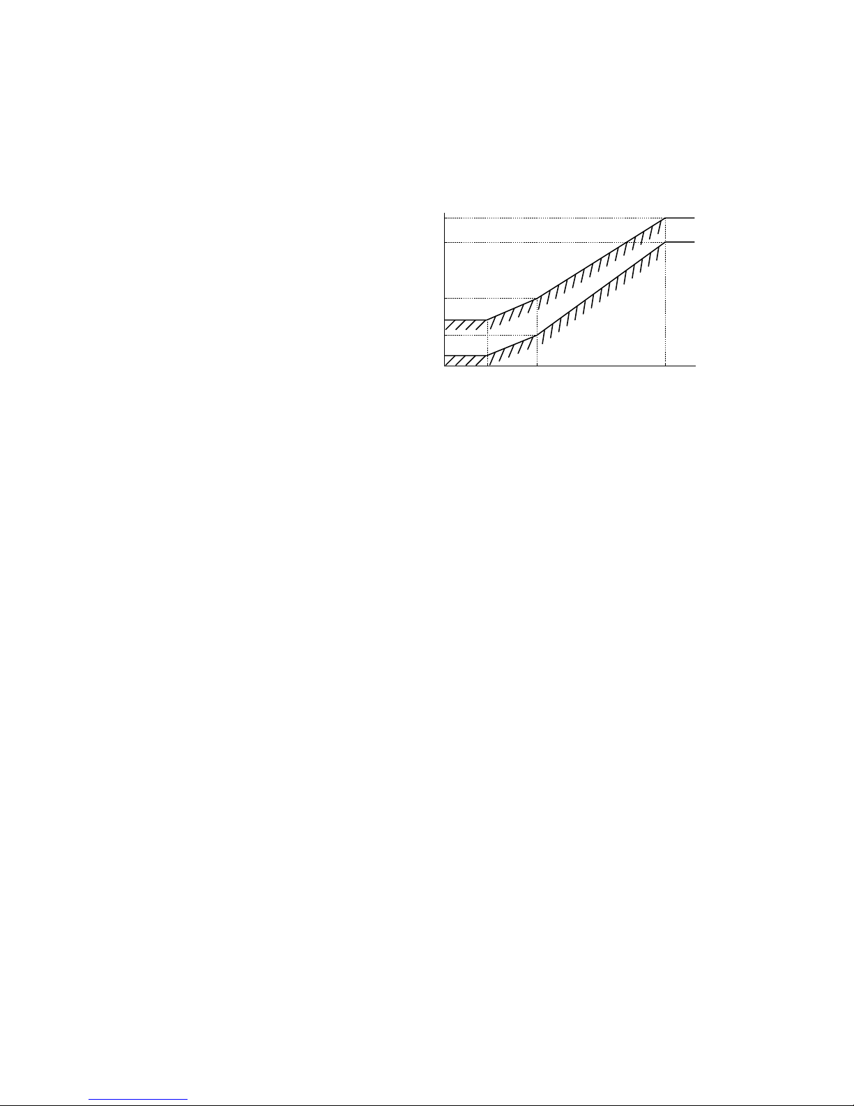
(8) Defrrosting (Master unit/Slave unit)
If the defrost starting conditions at the outdoor heat exchanger are established, defrost operation starts.
(a) Temperature conditions for defrosting
(i) Conditions for starting defrost
When all of following conditions are satised, defrost operation will be started.
1)
When the cu mulative operation time
of the compressor becomes 33 minutes
after co mp le ti on of pr ev io us defrost
operation, or it becomes 33 minutes after
heating operation starts.
2)
When 8 minutes have elapsed after one
compressor is turned ON from the state
of all compressors OFF.
3) When 8 minutes have elapsed after one
outdoor fan is turned ON from the state
of all outdoor fan OFF.
4) After all of the above conditions are satised, and
when the temperatures detected with the outdoor heat exchanger temperature thermistor (Tho-R1,-R2) and
outdoor air temperature thermistor (Tho-A) are below the defrost starting temperature mentioned in the above
graph continuously for 3 minutes.
(ii)
Conditions for finishing defrost
• Standard (J14 is shorted)
1) When the temperature detected with both outdoor heat exchanger temperature thermistors (Tho-R1 and
Tho-R2) is higher than 9ºC
2)
Or when 12 minutes have elapsed since defrosting started.
• Cold region setting (J14 is open)
1) When (Tho-R1 and Tho-R2)
>
=
9ºC is satised, after 2 minutes and 30 seconds have elapsed since defrosting
started, and when either of following conditions is satised, the defrosting end operation starts.
a)
2 minutes and 30 seconds have elapsed since the temperature of either Tho-R1 or Tho-R2 was 14ºC or
higher
b)
The temperature of either Tho-R1 or Tho-R2 is 30ºC or higher.
c) 14 minutes have elapsed since defrosting started.
2) When (Tho-R1and Tho-R2) < 9ºC is satised, after 2 minutes and 30 seconds have elapsed since defrosting
started, and when either of following conditions is satised, the defrosting end operation starts.
a)
5 minutes have elapsed since the temperature of either Tho-R1 or Tho-R2 was 14ºC or higher.
b) The temperature of either Tho-R1 or Tho-R2 is 30ºC or higher.
c) 14 minutes have elapsed since defrosting started.
-20 -15 6
Without J15
Cold region
specification
With J15
Outdoor air temp. (ºC) [Tho-A]
Cold region
Defrost start zone
Standard
(Factory setting)
Heat exchanger temp. (°C) [Tho-R]
Fig.1
-2
-6
-15
-19
-21
-25
-
17
-
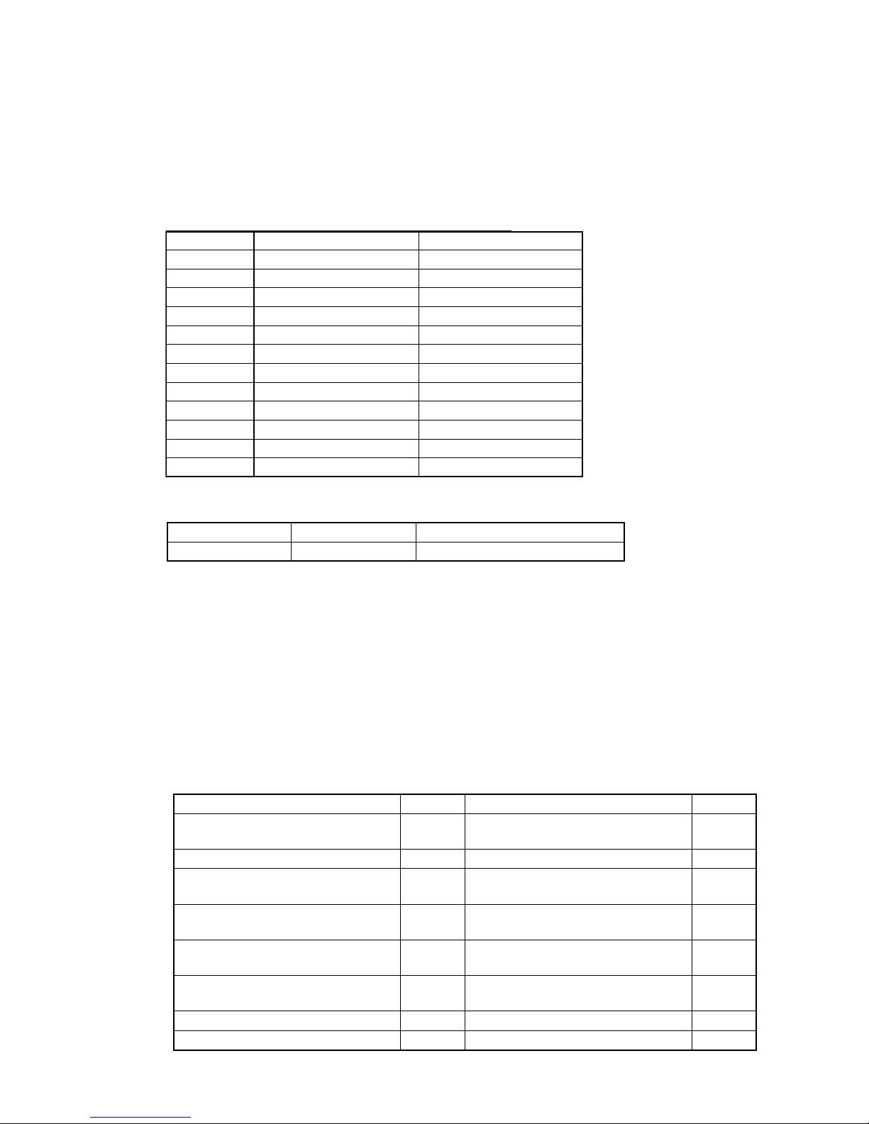
(9) Protective control
(a) Discharge pipe temperature control (Master unit/slave unit)
(i)
If the discharge pipe temperature (detected with Tho-D1, D2) exceeds the set value, it makes the compressor capacity
control performed and the solenoid valves SV1, 2 (for cooling down the compressor) open according to the compressor
Hz in order to suppress the discharge pipe temperature rising.
1) Compressor capacity control
2) Solenoid valve (SV1, 2) control for cooling down compressor
.
< ON conditions >
①
In the zone
A: SV1 is turned ON when Td1
>
=
115°C. SV2 is turned ON when Td2
>
=
115°C.
②
In the zone B: SV1 is turned ON when
Td1
>
=
110°C. SV2 is turned ON when Td2
>
=
110°C.
< OFF conditions>
①
In the zone
A: SV1 is turned OFF when Td1
<
=
108°C. SV2 is turned OFF when Td2
>
=
108°C.
②
In the zone B: SV1 is turned OFF when
Td1
<
=
103°C. SV2 is turned OFF when Td2
<
=
103°C.
(ii)
Discharge pipe temperature control and Error display
1) W
hen the discharger temperature exceeds 130°C or higher for 2 seconds continuously, it makes the compressor
stopped. And when the discharge pipe temperature decreases to lower than 90°C, it makes the compressor restarted
automatcally.
2) I
f this control [mentioned in (ii)-1)] is activates 5 times within 60 minutes, it makes the compressor anomalous
stop and displays E36, In case of anomalous stop, it cannot be operated again until the discharge pipe temperature
decreases to lower than 90°C for 60 minutes continuously.
(b) Current safe control
• Current safe control is done by both Master and Slave unit individually.
< Compressor capacity control >
1) Compressor
frequency is controlled by detecting the inverter primary current (T-phase) and the inverter secondary
current.
However under the following operating status
①
and ②, it does not detect the inverter current.
①
Actual compressor frequency N < 20Hz
②
During the period that actual
compressor frequency is decreasing or during the period of 1 second after the actual
compressor frequency decreased.
110 120
Discharge pipe temperature (°C) [Tho-D1, D2]
Retention
Compressor capacity is
reduced at 5-second intervals
Reset
40HZ
(33HZ)
45HZ
(38HZ)
• zone A • zone B
zone A
zone B
108 115
Discharge pipe temperature (°C) [Tho-D1, D2]
ON ON
SV1 : OFF
SV2 : OFF
SV1 : OFF
SV2 : OFF
103 110
Discharge pipe temperature (°C) [Tho-D1, D2]
Note (1) Value in ( ) are for the models FDC615, 680KXE6 and
FDC1180~1360KXE6
-
18
-
2) Initiation condition: When the detected current becomes following value.
①
W
ithin 2 minutes after starting operation of CM1 and CM2, the capacity control is done at the current safe value
for starting mentioned in a) and b)
②
During
capacity measurement mode, the capacity control is done at the current safe value for measurement mode
mentioned in a) and b)
a)
The inverter primary current (Current safe 1): See following graph
(At starting and at measuring mode, the current safe value is the value (23.5A) at 35ºC of outdoor air tem
-
perature)
b) The inverter secondary current (Current safe 2): 24A
(At starting and at measuring mode, the current safe values are same.)
* Both current safe values mentioned in a) and b) can be corrected by the code P21 of 7-segment input.
Correction value
α
= 3 to + 6 (0.5 interval)
Factory setting
α
= 0
3)
Control contents
①
The
frequency of all compressors currently operating in the same refrigeration system will be decreased at every
one second by 2-steps (Current safe 1: rst step, Current safe 2: second step). The compressor that receives cur-
rent safe control command rst decreases the frequency and when its frequency is retaining at certain frequency,
such retained frequency information is transmitted to master unit.
②
Master
unit will send the command to all other operating compressors in same refrigeration system to decrease
frequency up to the same frequency as the rst compressor reduced to according to the information of the rst
compressor.
③
After the frequency is decreased, if the inverter current within the detection range is still above the current safe
value, the procedure ① will be repeated.
④
After
the frequency is decreased, if the inverter current within the detection range is lower than the current safe
value, compressors will keep that frequency.
⑤
The minimum indicated frequency Ni by this control is 20Hz.
E
xample 1: In case of heat load zone 3 mentioned in Page 2, the operation of 20Hz×4 compressors is minimum (not
42Hz×4 mentioned in the table).
E
xample 2 : In case of heat load zone 2 mentioned in Page 2, the operation of 20Hz×2 compressors is minimum (not
42Hz×2 mentioned in the table).
Outdoor air temperature (°C)
Inverter current (A)
30
25
20
15
10
23.5
35 39 43 47 50
22.3
19.7
11.2
11.2
16.2
-
19
-
ON
ON
ON
ON
OFF
Master unit
(N=0)
Slave unit
(N=1)
CM01
(M=0)
CM02
(M=1)
Current safe
control
Retain
Release
PI control
CM11
(M=0)
CM12
(M=1)
OFF
OFF
OFF
⑥
When master unit retains the current safe control information in itself or receive the current safe control informa-
tion from slave unit, master unit send signal of “Current safe protective control” to the indoor units during retain-
ing those information.
4)
At-end condition: If either following condition
①
or
②
is established, the protective control 3) will end and return to
the PI control.
①
The detected inverter current is -1A
or lower of the current safe value for 3 minutes continuously.
②
The detected inverter current is lower than the current safe value for 6 minutes continuously
< Maximum compressor frequency control>
1)
By controlling the maximum compressor frequency according to the rising outdoor air temperature, it makes the in-
verter secondary current decreasing and protects the controller from rising temperature.
Compressor frequency is also controlled by detecting inverter secondary frequency
2) Initiation condition: Outdoor air temperature
>
=
35ºC ( For cooling operation)
3)
Control contents
①
Maximum compressor frequency is varied according to following chart.
Whichever the lower of maximum compressor frequency by this control or at normal operation has priority.
* Maximum compressor frequency can be corrected by the code P21 of 7-segment input.
Correction value
β
= 4 ×
α
(
α
: Correction coefcient of current safe value)
4) At-end condition: Initiation conditions are not established.
Outdoor air temperature (°C)
Maximum frequency (Hz)
120
100
80
60
40
120
113
96
76
50
120
113
96
76
50
37 39 43 47 50
-
20
-
(c) Power transistor temperature (PT) protective control (Master unit/Slave unit)
If the power transistor temperature exceeds 75°C, the compressor speed is controlled.
(d) Ventilation fan control for cooling inside control box (Master unit/Slave unit)
If the relationship between the outdoor air temperature (detected with Tho-A) and the inverter frequency (the frequency of
CM1 or CM2, whichever the higher) is in the ventilation fan ON zone in the gure mentioned below and when the CM1
or CM2 is operating, the ventilation fan FMC3 is turned ON.
If once it enters in the zone of ON or OFF, FMC3 control is retained for 1 minute before resetting.
However at the start and stop of compressor, 1 minute retention control is invalid.
When all compressors of the unit are stopped, this control is terminated.
(e) Protection for the number of connected indoor units
(i) When the number of connected indoor units exceeds 80 units, all corresponding units are stopped with the error of
excessive number of connected indoor units.
(ii)
The number of connected indoor units is checked when the automatic address setting is completed, or when turning
the power ON or starting operation of indoor units after completion of manual address setting.
(iii)
When the error of exessive number of connected indoor units (E43) occurs, the error code (E43) is diplayed up to
allowable maximum connected indoor units + 1unit on the LCD of remote controller, but in case of automatic
address setting E43 is dispalyed on all of connected indoor units.
(iv)
After 3 minutes or more has elapsed since power ON, the capacities of connected indoor units are summed, and if the
summed result exceeds the usage limitation in comparison with the capacity of connected outdoor units, it displays
error code (E43) and stops all units.
72 75
Speed is reduced once each minute
Retention
Power transistor temp. (°C)
Release
Inverter frequency (Hz)
120
50
20 35
Ventilation fan
OFF zone
Outdoor air temperature (°C)
Ventilation fan
ON zone
-
21 *
-
Contents displayed on 7-segment display at the combination error
(f) Protection for combination of outdoor units (Master unit)
The capacity of connectable outdoor units is checked when the communication check is performed after turning the power
ON.
If the checked result is other than the allowable combinations mentioned in the following table ① it is prohibited to start
operation due to outdoor unit combination error.
When this error occurs, the error code mentioned in the following table ② is displayed on the 7-segment display.
Combination list
Note (1) *1 Use FDC335KXE6-K. *2 Use FDC560KXE6-K.
Model
P735
P800
P850
P900
P960
P1010
P1065
P1130
P1180
P1235
P1300
P1360
HP
26 (12*1+ 14)
28 (14 + 14)
30 (14 + 16)
32 (16 + 16)
34 (16 + 18)
36 (18 + 18)
38 (18 + 20)
40 (20 + 20)
42 (20*2+ 22)
44 (22 + 22)
46 (22 + 24)
48 (24 + 24)
12 + 14
14 + 14
14 + 16
16 + 16
16 + 18
18 + 18
18 + 20
20 + 20
20 + 22
22 + 22
22 + 24
24 + 24
Normal combination (HP)
Code display area Data display area Contents of invalid operation
3OPE
Invalid combination of outdoor units
(10) Auto backup operation
(a) Classi-cation of auto backup operations
When the auto backup operation is enabled, anomaly stops are classifiedas follows and countermeasures are provided for
respective categories.
System stop: All stop including master/slave units
Unit stop: Stop in the unit of outdoor unit
Compressor stop: Stop in the unit of compressor
(b) Control contents of auto backup operation
(i) Condition of auto backup operation is established when the dip switch SW3-2 on the PCB of master unit is turned
ON (selected).
(ii) However, the switching of SW3-2 is effective only at the power on. (It does not become effective unless the power
supply is reset.)
(iii)
Anomaly contents in the following table are invalid and are not detected when the auto backup is effective.
Anomaly detection invalid code SW3-2ON Anomaly detection invalid code SW3-2ON
E32: Open L3 phase on power supply at
primary side
E45: Communication error between inverter
PCB and outdoor control PCB
E36: Discharge pipe temperature anomaly E48: Outdoor DC fan motor anomaly
E37: Outdoor heat exchanger and sub-cooling
coil temperature thernistor anomaly
E51: Power transister overheat
(Continuousness)
E38: Outdoor air temperature thermistor
anomaly
E53: Suction pipe temperature thermistor
anomaly
E55: Under-dome temperature thermistor
anomaly
E39: Discharge pipe temperature thermistor
anomaly
E40: High pressure anomaly
E56: Power transitor temperature thermistor
anomaly
E41: Power transister overheat
E42: Current cut
E59: Compressor startup failure
E60: Rotor position detection failure
○
○
○
○
○
○
○
○
○
○
○
○
○
○
○
○
-
22 *
-
(iv) If any anomaly occurs when the auto backup is effective, the operation output (CnH), Anomaly output (CnY), 7-seg-
ment display and LED show as follows.
1) At the system stop
Operation output on the master unit is turned OFF, the Anomaly output is turned ON, 7-segment display and
LED show the anomaly, and the remote controller displays E??. (To reset the anomaly, it is necessary to reset the
inspection from the remote controller.)
2) At the unit stop
On the unit only, the operation output is turned OFF, the Anomaly output is turned ON, 7-segment display and LED show
the anomaly and normal units continue their operation (stop).
To reset the state of anomaly on the unit the anomaly occurred, it depends on the condition to reset the state of each anomaly.
3) At the compressor stop
Only the compressor concerned stops, previous states are maintained on the operation output, anomaly output,
7-segment display and LED. To reset the state of anomaly on the compressor, it depends on the condition to reset
the state of each anomaly.
E31
E32
E36
E37
E38
E39
E40
E41
E42
E43
E45
E48
E49
E51
E53
E54
E55
E56
E59
E60
E61
E63
Duplicated outdoor unit address No.
Open L3 Phase on power supply at primary side
Discharge pipe temperature anomaliy
Outdoor air temperature thermistor anomaly
Discharge pipe temperature thermistor anomaly
High pressure anomaly
Power thansistor overheat
Current cut
Outdoor DC fan motor anomaly
Low pressure error
Suction pipe temperature thermistor anomaly
Under-dome temperature thermistor anomaly
Power transitor temperture thermistor anomaly
Compressor startup failure
Rotor position detection failure
Emergency stop
Anomaly contents
Anomalous stop of master outdoor unit Anomalous stop of slave outdoor unit
System stop Unit stop
Compressor stop
System stop Unit stop
Compressor stop
Remote controller
error display
Outdoor heat exchanger and subcooling
coil temperature thermistor anomaly
Communication error between inverter
PCB and outdoor control PCB
High pressure sensor/Low pressure
sensor anomaly
Power transister overheat (continuousness)
Excessive number of indoor unit connected,
excessive to tal capacity of connection
Communications error between the master
unit and slave units
Backup operation function is only for emergency purpose when one of compressors or one of units is damaged.
If backup operation is performed continuously for long period, it may cause the damage of good compressors.
Accordingly be sure to repair the damaged unit or to replace the damaged compressor and to cancel the
backup operation within 48 hours after starting backup operation.
(c) Prohibiting conditions of auto backup operation
(i) When the conditions of oil return control are not established
(ii) When the backup operation time has exceeded the limit value
(d) Control after the conditions to prohibit the auto backup operation have been established
All compressor stop, and the error display [E-XX] is shown on the 7-segment display and the remote controller.
In this state, the inspection reset of remote controller is effective. →[E-XX] is displayed continuously on the remote controller.
-
23 *
-
(11) Test run
(a) This control can be performed from the master unit, not from the slave unit.
If this control is done from the slave unit, the following display is shown on the 7-segement display.
The display returns to normal display if the test run control switch is reset.
(b) Test run from master outdoor units with dip switches SW5-1 and SW5-2.
Take note that this operation has priority over other optional devices such as center console and etc.
This operation status is transmitted to the optional devices.
(Note) Test run operation by external input is also available with following method. (Refer next page for detail)
• Select the external input terminal (CnS1) and set 7-segment [P11]-[6] for the function of SW5-1, and select the external input terminal (CnS2) and
set 7-segment [P12]-[7] for the function of SW5-2.
• Other combination of external input terminals (CnS1, CnS2, CnG1, CnG2) and of setting function with 7-segment ([P11], [P12], [P13], [P14] and
-[6], -[7]) are avilable to use.
(c) Starting conditions of test run operation
(i) Dip switch SW5-1 is turned ON. However the input before the power ON is invalid.
(ii) The dip switches SW3 and SW5, other than SW5-1and SW5-2, should be turned OFF.
However, regarding the dip switch SW3-2 for automatic backup operation, it is invalid during test run operation
regardless whether SW3-2 is turned ON (valid) or OFF (invalid).→In order to check trouble during test run operation.
(d) Control during test run (If indoor units are normal)
(i) Heating operation is performed with SW5-2 OFF, while cooling operation is performed with SW5-2 ON.
(ii) Indoor EEV control at the end of test run is depended on the specifications of the indoor unit.
(iii) Cooling operation: Compressor frequency control is depended on the cooling low pressure control.
(iv) Heating operation: Compressor frequency control is depended on the heating high pressure control.
(e) Ending conditions of test run operation
Test run operation is terminated if one of following conditions is satisfied.
(i) Test run operation ends when the dip switch SW5-1 is turned OFF.
(ii) When the operation is stopped by the error control during test run, the error is displayed same as the normal operation
and the state of error stop is retained even if SW5-1 is turned OFF.
Code indicator Data indicator Contents of invalid operation
10OPE
Slave setting is invalid.
ON
SW5-1
SW5-2
OFF
ON
OFF
Test run for heating
Test run for cooling
Normally operation and after test operation
CnS1
Shorted CnS2
Open Test run for heating
Shorted Test run for cooling
Open Normal operation and after test operation
Delete
-
24
-
(1) External input and demand input (Master unit/Slave unit)
(a) Operation permission or prohibition mode
(Note) Following explanation is based on using CnS1 terminal and setting function [P11]-[0] with 7-segment display.
However other terminals can be used with following function setting of 7-segment display.
CnS2: [P12]-[0] CnG1: [P13]-[0] CnG2: [P14]-[0]
1) Opearation permission or prohibition mode is switched with the connector (CnS1) and the Jumper wire (J13) on the
outdoor control PCB after setting function [P11]-[0] (Factory setting) with 7-segment display
J13: Switching of CnS1 input method
J13 shorted: Level input by CnS1
J13 open : Pulse input by CnS1
2) Operation permission/prohibition control by the external input CnS1 to outdoor unit.
Note (1) Factory setting J13: Shorted, CnS1: Shorted (Short pin is connected)
3) The operation condition is displayed on the LCD of remote controller and it is transferred to optional centralized controller
4) When the operation command from remote controller is not accepted by this control, "Center" is displayed on the
LCD of remote controller. (See item 5 mentioned next page)
(B)
Optional controls
• External input terminal
①
4 External input terminals (CnS1, CnS2, CnG1 and CnG2) are provided. (See g-1)
②
Each external input terminal can be changed its function by allotting the external input function No. of P11-P14 selected
with 7-segment respectively. (External input functions of the code P11-P14 are shown in g-2)
③
The following function is effective, when the external input function of PXX-"X" is allotted and the signal is input
to the
external terminal of CnXX.
(Example) If CnS1 terminal is used for demand control (pulse input), allot the "1" of P11 and open J13, and if CnS2 terminal is
used for demand control (level input), allot the "1" of P12 and short J13.
(Note) More than one function cannot operate at same time.
*1 "Setting" means;
Master : Set only the master unit. (No necessary to set the slave unit)
Master/Slave: Set both master/slave unit same.
External input terminal External input function allotment of 7-segement
Terminal Specication Factory setting Code Function No. Factory setting
CnS1 No volatage contact (DC12V) Shorted P11 "0"-"9" "0"
CnS2 No volatage contact (DC12V) Shorted P12 "0"-"9" "1"
CnG1 No volatage contact (DC12V) Open P13 "0"-"9" "2"
CnG2 No volatage contact (DC12V) Open P14 "0"-"9" "3"
Fig-1
Setting *1 Allotment of external input function (P11-P14)
External input terminal
shorted
External input terminal
open
Master unit "0": External operation input Operation permission Operation prohibition
Master unit "1": Demand input Invalid Valid
Master unit "2": Forced cooling/heating input Heating Cooling
Master unit "3": Silent mode input 1 Valid Invalid
Master unit "4": Spare - -
Master/Slave unit "5": Outdoor fan snow protection control input Valid Invalid
Master unit "6": Test run external input 1 (Equal to SW5-1) Test run start Normal operation
Master unit "7": Test run external input 2 (Equal to SW5-2) Cooling test run Heating test run
Master unit "8": Silent mode input 2 Valid Invalid
Master unit "9": Spare - -
Fig-2
Input: CnS1
Switching CnS1
input method:J13
CnS1: Switching operation
permission/prohibition mode
Shorted (Level input)
Shorted
Shorted
Open
Open
Operation prohibition mode
Operation permission mode
Operation permission mode
Operation prohibition mode
—
(NOP)
Switching operation permission/
Operation prohibitiion mode (Reversal)
Shorted (Level input)
Open (Pulse input)
Open (Pulse input)

-
25
-
(b) Demand control
(Note) Following explanation is based on using CnS2 terminal and setting function [P12]-[1] with 7-segment display.
However other terminals can be used with following function setting of 7-segment display
CnS1: [P11]-[1] CnG1: [P13]-[1] CnG2: [P14]-[1]
1) Demand control or normal control is switched with the connector (CnS2) and the jumper wire (J13) on the outdoor
control PCB after setting function [P12]-[1] (Factory setting) with 7-segment display.
J13: Switching of CnS2 input method
J13 shorted: Level input by CnS2
J13 open : Pulse input by CnS2
2) Demand control/Normal operation by the external input CnS2 to outdoor unit.
Note (1) Factory setting J13: Shorted, CnS2: Shorted (Short pin is connected)
3) The operation condition is displayed on the LCD of remote controller and it is transferred to optional centralized
controller
①
J13 − Shorted
②
J13 - Open
5)
CnS1 performs the following operation according to switching the jumper wire (J13) shorted or open. In case of
pulse input, the pulse width is 500ms or larger.
PUSH
CnS1 input OFF (Open)
Remote controller operation
Remote controller display
Air-conditioner operation/stop
PUSH PUSH PUSH
OFF
Center Remote
ON (Shorted)
Center
OFF
OFF (Open)
Air-conditioner ON OK
OFF ONON
Remote controller operation
Remote controller display
Air-conditioner operation/stop
Center Center Center
Remote
Remote
Air-conditioner ON OK
CnS1 input
OFF
OFF
ON
ON OFF OFFON
OFFON
PUSH PUSH PUSH PUSH PUSH
Input: CnS2
Switching CnS2
input method:J13
CnS2: Switching operation
permission/prohibition mode
Shorted (Level input)
Shorted
Shorted
Open
Open
Demand control
Normal operation
Normal control
Demand operation
—
(NOP)
Switching Demand control/
Normal operation (Reversal)
Shorted (Level input)
Open (Pulse input)
Open (Pulse input)
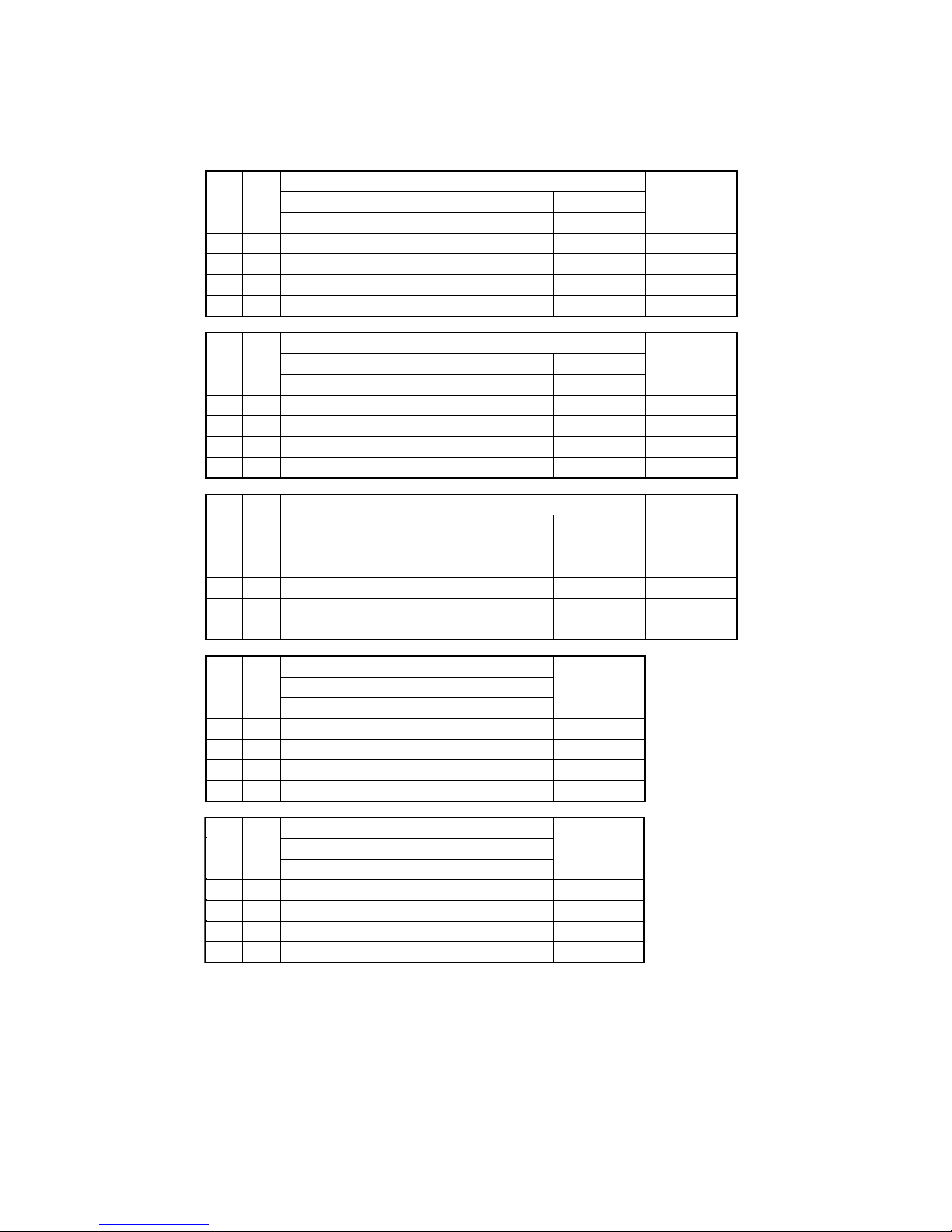
-
26
-
5) This control has priority over the controls of 4-way valve safeguard, compressor protective start operation, defrost
operation, oil equalized operation and oil return operation.
4)
Demand control
Demand ratio can be changed with the dip switches (SW4-5, SW4-6) on the outdoor control PCB.
SW4-5, SW4-6 demand switch: 0 - open, 1 - shorted
400
14
54Hz × 2
78Hz × 1
54Hz × 1
OFF
SW
4-5
0
1
0
1
0
0
1
1
450
16
60Hz × 2
46Hz × 2
60Hz × 1
OFF
504
18
70Hz × 2
52Hz × 2
70Hz × 1
OFF
560
20
80Hz × 2
60Hz × 2
78Hz × 1
OFF
615
22
72Hz × 2
56Hz × 2
36Hz × 2
OFF
80
60
40
0
SW
4-6
Upper limit operation Hz of compressor
Compressor
output (%)
SW
4-5
0
1
0
1
0
0
1
1
680
24
80Hz × 2
60Hz × 2
40Hz × 2
OFF
735
26 (12+14)
50Hz × 4
74Hz × 2
50Hz × 2
OFF
800
28 (14+14)
54Hz × 4
78Hz × 2
50Hz × 2
OFF
850
30 (14+16)
58Hz × 4
42Hz × 4
58Hz × 2
OFF
900
32 (16+16)
60Hz × 4
46Hz × 4
62Hz × 2
OFF
80
60
40
0
SW
4-6
Upper limit operation Hz of compressor
Compressor
output (%)
SW
4-5
0
1
0
1
0
0
1
1
960
34 (16+18)
66Hz × 4
50Hz × 4
66Hz × 2
OFF
1010
36 (18+18)
70Hz × 4
52Hz × 4
70Hz × 2
OFF
80
60
40
0
SW
4-6
Upper limit operation Hz of compressor
Compressor
output (%)
SW
4-5
0
1
0
1
0
0
1
1
1065
38 (18+20)
74Hz × 4
56Hz × 4
76Hz × 2
OFF
1130
40 (20+20)
80Hz × 4
60Hz × 4
78Hz × 2
OFF
1180
42 (20+22)
84Hz × 4
64Hz × 4
42Hz × 4
OFF
80
60
40
0
SW
4-6
Upper limit operation Hz of compressor
Compressor
output (%)
SW
4-5
0
1
0
1
0
0
1
1
1235
44 (22+22)
72Hz × 4
56Hz × 4
36Hz × 4
OFF
1300
46 (22+24)
76Hz × 4
56Hz × 4
38Hz × 4
OFF
1360
48 (24+24)
80Hz × 4
60Hz × 4
40Hz × 4
OFF
80
60
40
0
SW
4-6
Upper limit operation Hz of compressor
Compressor
output (%)
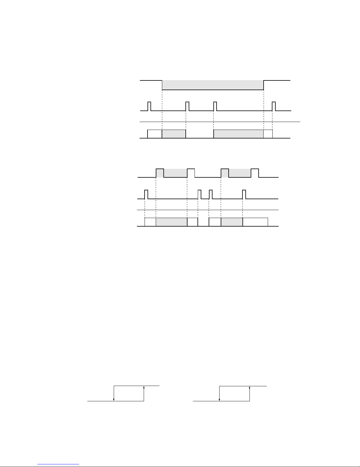
-
27
-
6) CnS2 performs the following operation according to switching the jumper wire (J13) shorted or open.
In case of pulse input, the pulse width is 500ms or larger.
①
J13 − Shorted
②
J13 - Open
(2)
Silent mode control
(Note) Following explanation is based on using CnG2 terminal and setting functionwith 7-segment display [P14]-[3] or -[8]
However other terminals can be used with following function setting of 7-segment display
CnS1: [P11]-[3] or -[8] CnS1: [P12]-[3] or -[8] CnG1:
[P13]-[3] or -[8]
(a) Silent mode is commanded either from the indoor unit (remore controller setting) or from the master outdoor unit (CnG2).
(b) When the "Silent mode start" signals is received from one of indoor units, it enters the silent mode operation.,
(c) When CnG2 of master unit is shorted after setting function [P14]-[3] (Factory setting) with 7-segment display, it enters the
silent mode operation. (If the signal is input to the slave unit, it is invalid)
(d) When the "Silent mode start" signal from indoor unit and the "Silent mode" signal from outdoor unit are received, it enters
the silent mode operation under "or"condition.
(e)
When silent mode signals from all indoor units become "Silent mode end" and when silent mode signal input to CnG2 on
outdoor unit becomes open, the silent mode operation is reset.
(f)
The silent mode operation is effective within the following temperature range.
• Cooling • Heating
29 31°C
Outdoor air temperature
Reset
Effective
2 4°C
Outdoor air temperature
Reset
Effective
PUSH
CnS2 input
OFF OFF
ONON
Compressor OFF
Compressor OFF
PUSH PUSH PUSH
Remote controller operation
Remote controller display
Air-conditioner operation/stop
Remote
ON (Shorted) ON (Open) ON (Shorted)
Demand control
NormalNormal
CnS2 input
Compressor OFF
Compressor OFF
Remote controller operation
Remote controller display
Air-conditioner operation/stop
Remote
Demand control Demand control
OFFOFF
ONON
PUSH PUSH PUSH PUSH
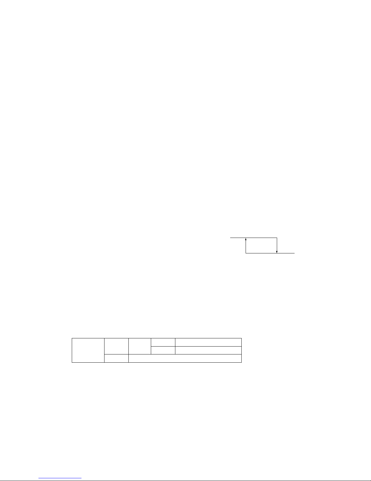
-
28
-
(3) Outdoor fan snow protection control (Master unit/Slave unit)
(Note) Following explanation is based on setting function with 7-segment display [C75].
However the following terminals and 7-segment function settings are available to use.
CnS1: [P11]-[5] CnS2: [P12]-[5] CnG1:
[P13]-[5]
CnG2: [P14]-[5]
(a) The setting of this control should be done not only on the master unit but also on the slave unit, because the fans of master
unit and the slave unit are controlled independently.
(b)
The control is enabled /disabled by selecting [0] or [1] displayed at 7-segement LED of master/slave units.
(c) Operation method of outdoor fan snow protection control
(i) Set the code [C75] on 7-segment display
(ii) “0” or “1” is displayed at the data display area of 7-segment LED.
“0”: Outdoor fan snow protection control is disabled (Factory setting)
“1”: Outdoor fan snow protection control is enabled
(iii) Press SW7 (Data write/delete) for 3 seconds continuously
(iv) “0” or “1” blinks every 0.5 second at the data display area of 7-segment LED.
(v) Press SW8 (one digit) to toggle the display between “0” and “1”.
(vi) If SW7 is pressed for 3 seconds continulouly while “0” and “1” are blinking, “0” or “1” at the data display area of
7-segment LED stops blinking.
With this operation, the enabled/disabled setting of outdoor fan snow protection control is saved in the memory of
EEPROM, and henceforth the outdoor fan is controlled according to the contents of memory.
(vii)
Contents of outdoor fan snow protection control are retained even if the power is turned off and backed on again.
(d) Contents of outdoor fan snow protection control
(i) At the status of all stop or emergency stop, if the outdoor air temperature drops 3°C or lower, all of outdoor fans are
operated at the maximum speed (4th speed) once every 10 minutes.
(ii)
The outdoor fan runs for 30 minutes
(iii) During this snow protection control, the magnetic
contactor 52C1 of the compressor is ON
(4) Forced cooling /heating operation (Master unit)
(Note) Following explanation is based on using CnG1 terminal and setting function [P13]-[2] with 7-segment display.
However other terminals can be used with following function setting of 7-segment display.
CnS1: [P11]-[2] CnS2: [P12]-[2] CnG2:
[P14]-[2]
(a) When SW3-7 on the outdoor control PCB is turned ON after setting function [P13]-[2] with 7-segment display, if CnG1 is
shorted, forced heating operation is performed, but if CnG1 is open, forced cooling operation is performed.
(b)
If the different mode from the forced operation mode is commanded from indoor unit, the "mode unmatch" message is
displayed on the LCD of remote controller and the operation is entered in FAN mode.
(5)
Emergency stop control
When one of indoor units receives the emergency stop signal through CnT terminal on the indoor control PCB from the device
like as refrigerant leakage detector and that information is tarnsmitted to the outdoor unit, the outdoor unit stops opeartion and
emergency stop error message transmitted to all indoor units running.
It is able to make the emer
gency stop function effective by remote controller indoor function setting.
(a) When the outdoor unit receives the “Emergency stop” command from the indoor unit, it makes all stop by error.
(b) And the “Emergency stop” command is transmitted to all indoor units and error code “E63” is displayed.
(c) When the outdoor unit receives the “Emergency stop reset” command from the indoor unit, the “Emergency stop reset”
command is transmitted to all indoor units.
SW3-7
ON CnG1
Open Operation in cooling only
Shorted Operation in heating only
OFF Normal operation
3 5
Outdoor air temperature (°C)
Fan OFF
Fan ON
 Loading...