

Mitsubishi Heavy Industries FDC258HEN3A, FDCP258HEN3A, FDC308HEN3, FDCP308HEN3, FDC308HES3 Service Manual
...
AIR CONDITIONING & HEAT PUMP SYSTEMS
SERVICE GUIDE
Including outdoor unit (FDC 6 Series and 8 Series)
FDT 4-Way Cassette
FDEN Ceiling Suspended
FDKN Wall Mounted
FDR Ducted Cassette
FDU Ducted - High Static
This guide is to assist
site service engineers
with commissioning
of systems and to
provide information
for maintenance and
fault finding.

CONTENTS
Operation Pages 1 - 15
Wireless Remote Controller Page 1
Wired Remote Controller Page 2
Outline of Microcomputer Control Function Page 3
Operation Control Function by the Wired Remote Controller Page 11
Operation Control Function by the Outdoor Controller Page 12
Safety Precautions Page 16
Maintenance Pages 17 - 31
Servicing Page 17
Troubleshooting for Refrigeration Circuit Page 18
Diagnosing of Microchip Circuit Page 19
1
MODE TEMP ON/OFF
AIR FLOW FILTER
FAN SPEED
SET
TIMEACL
TIMER
AUTO COOL DRY FAN HEAT
FILTER
°
C
AM
PM
ON
AM
PM
OFF
FAN HI LO
8.4
OUTLINE OF OPERATION CONTROL BY MICROCOMPUTER
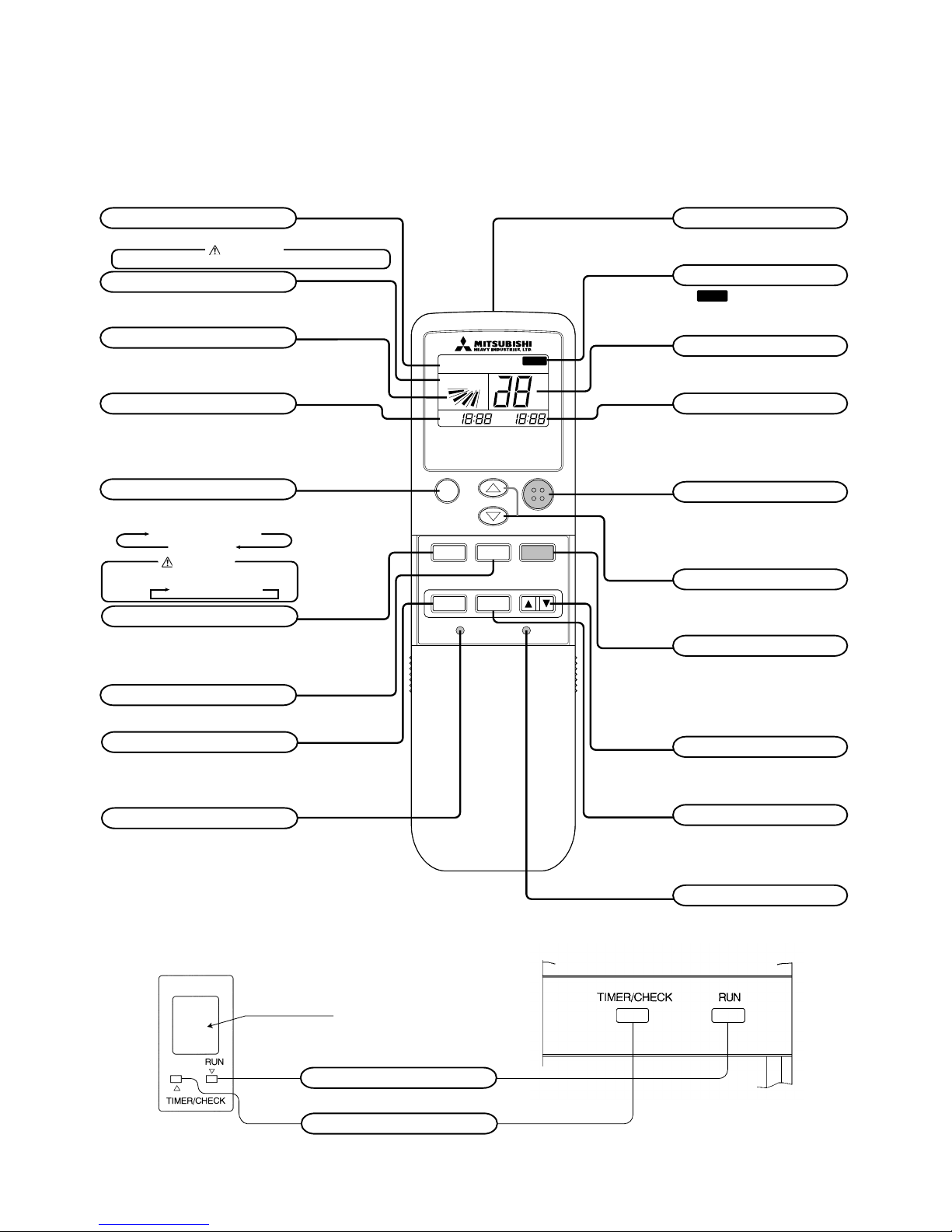
(1) Wireless remote controller
Models FDTN (P), FDEN (P), FDKN (P) series
(a) Remote controller
OPERATION MODE indicator
Indicates selected operation mode
Fan speed
Indicates the selected fan speed
Timer ON time
Indicates the timer ON time.
When the timer mode is “CONT” or “OFF”,
the present time is indicated.
FAN SPEED button
Every time when the button is pressed, the
mode is sequentially changed HI →LOW.
Timer mode button
Every time when the button is pressed, the
mode is sequentially changed CONT → ON
→ OFF → PROGRAM.
Reset switch
Used to reset the microcomputer when something is wrong on the remote controller display.
• Above figure shows all indications for the
purpose of explanation, but practically
only the pertinent parts are indicated.
OPERATION MODE select button
This button, whenever pressed, changes the
mode in the following order.
Auto swing
Indicates the selection of swing louver.
CAUTION
Cooling only air-conditioner has the display of “COOL”, “DRY” and “FAN” only.
Air flow direction button
Used to start or stop the swing louver.
Signal sender
Signals are sent to the air conditioner
from here.
Filter reset indicator
The
FILTER
mark is indicated when the
FILTER RESET button is pressed.
Temperature indicator
Set temperature is indicated.
Timer OFF time
Indicated the timer OFF time.
When the timer mode is “CONT” or
“OFF”, there is no indication.
ON/OFF button
When the button is pressed, the air conditioner
is started, and when the button is pressed once
again, it is stopped. (When the air conditioner
is stopped, the present time only is indicated.
When the air conditioner is operating, details
of setting are indicated.)
ROOM TEMP. button
Room temperature is set within the
range of 18-30˚C by operating the ∆ ,
∇
or button.
Filter button
Used to reset (turn off) the filter sign.
(Press for more than 1 second.)
Press the button only after completing
the filter cleaning.
TIME button
Used to set the present time and the timer
operation time.
Set button
Used to switch from the hour to minute or vice
versa when setting the present time or timer
operation time.
Clock switch
Press this before setting the present time.
(b) Indoor unit indicators
Model FDTN(P) series
Model FDKN (P) series
➞
AUTO ➞ COOL ➞ DRY
HEAT FAN
Remote controller
signal receiver.
RUN LAMP (GREEN)
Light up : Air conditioner is operating.
TIMER/CHECK (YELLOW)
Light up : Timer mode operating.
Flashing : When some error occurs.
CAUTION
Cooling only air-conditioner changes the mode in the following order.
COOL➞DRY➞FAN
2
Remote controller
signal receiver
RUN CHECK
ON/OFF
Heavy Duty
CHECK LAMP (YELLOW)
When a malfunction occurs,
the lamp flashing.
RUN LAMP (GREEN)
Illuminates during operation.
BACK UP SWITCH
When the remote controller is missing or defective, this switch can start
and stop the air conditioner.
Use the back up switch when the battery is exhausted, or when the remote controller is missing or defective.
Usually operate the air conditioner
with remote controller.
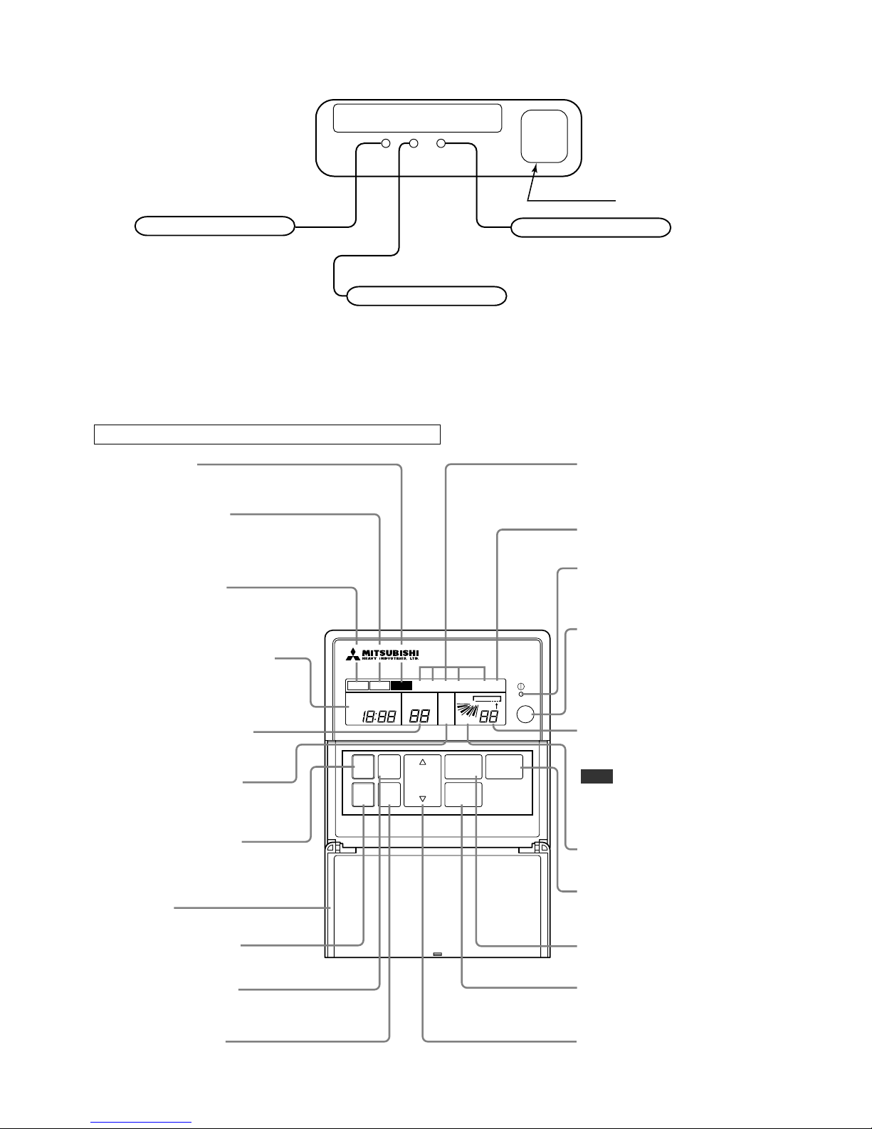
(2) Wired remote controller
Models FDT, FDR, FDU, FDFL series
FDR, FDU and FDFL series are not provided with AUTO SWING switch.
Panel shown below will appear if you open the cover. All contents of display on the LCD are indicated simultaneously for the purpose of explanation.
Pull the knob on the cover to this side to open it downward.
FILTER
RESET
CHECK
FAN
SPEED
AUTO
SWING
TIMER
SET
MODE
TEMP
TIME
PROGRAM TIMER
ON
OFF
PM
AM
SET TEMP
E
°C
Lo
Mi
Hi
FAN
°C
CENTER REMOTE
AUTODRYCOOLFANHEAT HEAT
Filter reset switch
Use this switch to reset (erase) the filter
sign display.
(Press the switch after cleaning the air filter.)
Filter sign
When this sign is indicated, clean the filter.
Remote display
This is displayed when the unit is controlled
with an individual controller during normal operation.
(Also displayed when the air conditioner is stopped.)
Inspection switch
Use this switch when servicing the unit.
Operation mode display
Displays the operation mode that has
been selected.
(Cooling only air-conditioner has the display
of "COOL" ,"DRY" and "FAN" only.)
Fan speed display
Displays the fan speed that has been set.
Operation/
Inspection indicator lamp
During operation: Green lamp flashes.
In case of error: Red lamp flashes.
On/Off switch
Use this switch to start or stop the
air conditioner.First push on the
switch starts the unit and second
push stops it. (The switch can be
operated without opening the cover.)
Fan speed switch
Use this switch to set a fan speed.
Mode switch
Use this switch to select operation
modes.
Cover
Heating
preparation display
Timer switch
Use this switch when selecting contents of timer operation.
Set switch
Use this switch to set a time for the timer.
Temperature/
Time setting switch
Use this switch to set the room
temperature or time on the timer.
Auto swing switch
Use this switch to operate or stop
the swing louver.
Auto swing display
Indicates the swing louver condition.
Setting
temperature display
Displays the temperature
that has been set.
Return air
temperature display
Displays the return air temperature.
Indicated value may be different
from actual reading on a thermometer
or other instrument but this is not
necessarily an error.
Note
Outdoor No.
Central display
This is displayed when the unit is
controlled with the optional central console.
Timer operation display
Contents of timer operation are displayed.
(Also displayed when the air conditioner
is stopped.)
FILTER
HOT
KEEP
Model FDEN (P) series
3
(3) Outline of microcomputer control function
(a) Operation control function by the indoor controller
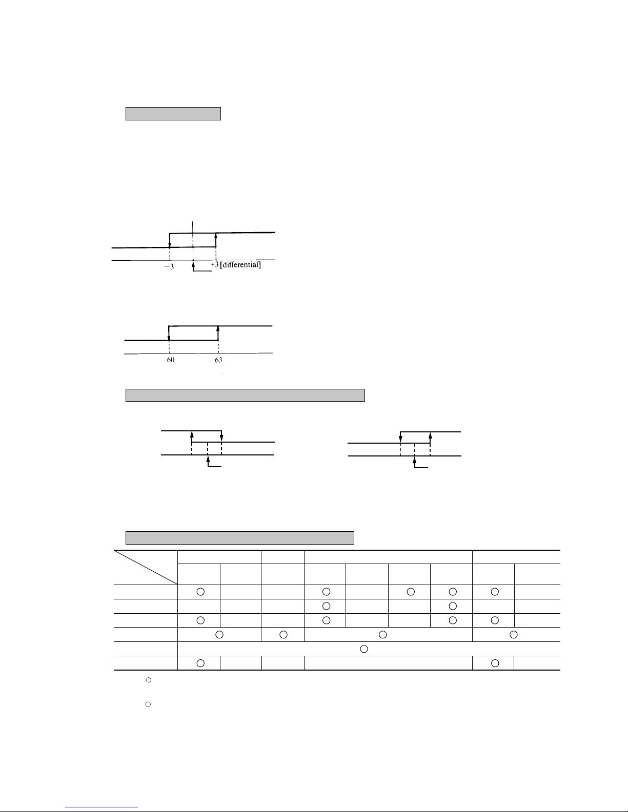
1) Automatic operation (Only heat pump type)
If the Auto mode is selected on the remote control device, the selection of cooling or heating can be made automatically
depending on the room temperature (and the temperature of indoor heat exchanger). (When the switching between the
cooling and the heating is made within 3 minutes, the compressor will not operate for 3 minutes.) This will make much
easier the switching of cooling/heating at the change of season and can be adapted to the unmanned operation at bank
cash dispenser.
Notes (1) During the automatic switching of cooling/heating the
room temperature is controlled based on the setting
of room temperature (DIFF:±}1 deg)
(2) If the temperature of indoor heat exchanger rises be-
yond 63˚C during the heating operation, it is switched
automatically to the cooling operation. For an hour
after this switching, the heating operation is suspended
regardless of the temperature as shown at left.
Temperature difference between thermostat set temp.
and return air temp. (Detected by ThI-A)
Note(1)
:ON
× :OFF
/ × :According to control other than temperature control.
Thermostat
ON
Cooling Fan Heating Dry
Control part
Compressor
× ×
×
×
4-way valve × × ×
×
× × ×
Outdoor fan
× ×
×
×
×
Indoor fan
/ ×
Louver motor
/ ×
Condensate motor
× (2min. ON) × (2min. ON)
× (2min. ON)
× (2min. ON)
Thermostat
OFF
HOT START
Defrost
ThermostatONThermostat
OFF
ThermostatONThermostat
OFF
3) Control parts operation during cooling and heating
2) Room temperature control (Differential of thermostat)
Temperature difference between thermostat set
temp. and return air temp. (Detected by ThI-A)
Function
Heating operation
OFF (52C)
+1
-1
Set temp.by thermostat
Cooling operation
OFF (52C)
+1
-1
Set temp.by thermostat
ON (52C)
Heating operation
Cooling operation
Setting room temp.
Room temp. (detected at Th
1-A
) [deg]
Ready for
heating
Suspended heating operation
Indoor heat exchanger temperature (˚C)
–
4
Notes (1)
Operation block A
B : Normal cooling operation for 16 minutes after operation is started.
Operation stops by thermostat when the set temperature is reached.
After 16 minutes, normal thermal drying operation starts.
Operation block
C D : Operation as above is performed for 8 minutes.
After 8 minutes, normal thermal drying operation starts.
(2) In normal operation, the temperature is checked at 8 minute intervals after normal thermal drying
operation is started, to determine which operation block is to the selected.
Operation block
A thermal drying is carried out if the thermostat set temperature is constant.
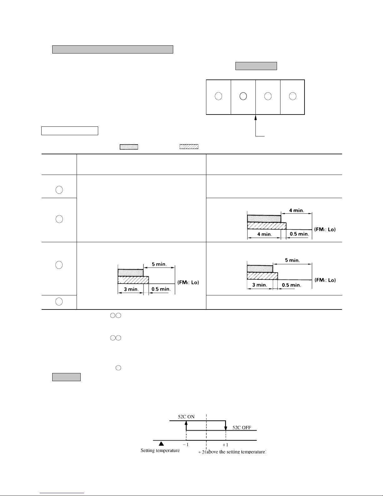
4) Dehumidifying operation (“THERMAL DRY”)
The compressor, the indoor fan motor and the outdoor fan motor
are operated intermittently under thermistor (ThI-A) control according to the appropriate operation block, to provide cooling operation for the dehumidifying.
Operation block
D C B A
Set temp. by thermostat
Pattern of operation
Operation
block
Thermal drying starting
(for 8 or 16 minutes after operation started)
A
(16 minutes)
• Cooling operation (Thermostat ON)
• Indoor fan operating with the setting air flow.
• When the thermostat is turned off, the indoor fan operates
for 30 seconds with the Lo operation in the wind blowing
mode and then stops.
(8 minutes)
Continuous cooling operation (FMI:Lo)
B
(8 minutes)
CM, FM0
FMI
C
(8 minutes)
CM, FM0
FMI
(8 minutes)
CM, FM0
FMI
D
(8 minutes) All stoppage
5) Hot spurt (Only heat pump type)
In the hot spurt mode, the control is conducted at the level +2 higher than the setting temperature at the start of heating operation.
The hot spurt is canceled either after the initial thermostat OFF, when the indoor heat exchanger temperature reaches 61˚C or 60
minutes after the start of the mode.
Room temperature (deg)
CM, FMO: ON FMI : ON
Normal thermal dry operation
(after completion of thermal drying)
Low
-2
+3
High
5
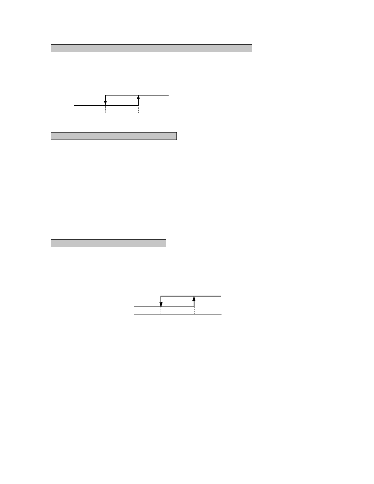
6) FM control with the heating thermostat turned off (For cold draft prevention) (Only heat pump type)
In order to prevent a cold draft while the heating thermostat is turned off, the indoor blower is controlled in response to the
temperature of the indoor heat exchanger as illustrated below. It should be noted that if SW3-4 on the indoor PCB is turned off, the
indoor blower will stop so far as the temperature of the indoor heat exchanger is lower than 40˚C. It will be turned to the Lo
operation 5 minutes later.
7)
Hot start (Cold draft prevention during heating) (Only heat pump type)
1) If the indoor heat exchanger temperature is lower than 30˚C when the heating operation has started, the following indoor
blower control is performed.
(1) In case of the thermostat off condition: Lo operation
(2) In case of the thermostat on condition : Stop
(3) If the indoor heat exchanger temperature exceeds 30˚C or 7 minutes after the beginning of hot start, the hot start
terminates and it returns to the setting airflow of the blower.
2) If the indoor heat exchanger temperature is lower than 30˚C when the unit is heating under the thermo-ON condition, the
indoor fan operates in the Lo mode. As the temperature rises higher than 30 ˚C or 7 minutes after the beginning of hot start,
the hot start terminates and it returns to the setting air flow.
8)
Indoor fan control during defrost operation (Only heat pump type)
1) The indoor fan operation is changed from the setting airflow to the Lo operation 40 seconds before the start of defrost
operation (when the defrost thermostat is turned ON) and stops if the indoor heat exchanger temperature drops below 20˚C.
2) After the stop as described in 1)-above, the control will be conducted as illustrated below depending on the indoor heat
exchanger temperature.
3) If the indoor heat exchanger temperature rises beyond 30˚C of 7 minutes after the end of defrosting, the indoor fan control
related to the defrosting is completed.
Note (1) After the thermostat is reset, it returns to the hot start
control.
Indoor heat exchanger temperature(˚C)
(Setting air flow)
40
45
Lo
20
30
Lo
Stop
6
9) Condensate pump motor (DM) control (Only FDTN (P), FDT, FDR models)
During the cooling or Dehumidifying operation, the condensate pump motor (DM) is synchronized with the start of compressor
operation. If the operation is switched from the operation stop, error stop, thermostat stop and the cooling of defrosting operation
to the fan or heating operation, the drain motor continues to operate for 2 minutes after the switching.
Overflow detection by means of the float switch is always on regardless of the operation mode. If an overflow occurs (or the float
switch is not connected or the wire is broken), the operation is interrupted as the error stop and the drain motor is operated until the
state of float switch is normalized.
10)
Defrost control (FDC 6 series only)
Defrost operation is precisely controlled with the defrost thermostat (23DH
1, 2) and a timer.
a) Defrost starting conditions
Defrost operation will start only when all of following conditions are met.
1) When the compressor operation time accumulated after the start of heating operation exceeds 30 minutes.
2) When the compressor operation time accumulated after the end of defrost operation exceeds 45 minutes.
3) When the defrost thermostat (23DH1) is turned ON (-6˚C)
b) Defrost terminating condition
If the defrost thermostat (23DH2) is turned OFF (12˚C) or 12 minutes after the start of defrost operation, the defrost opera-
tion is canceled and it returns to the heating operation.
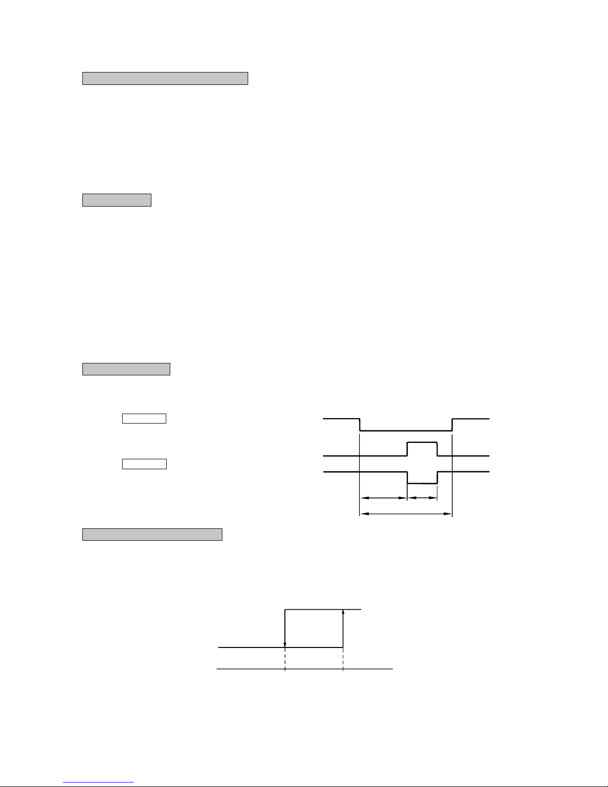
11)
4-way valve control (1 phase models only)
In order to maintain the pressure balance after the stop of compressor during cooling, dehumidifying and heating operation. the 4-
way valve is controlled repeatedly as illustrated below.
12)
Frost prevention during cooling (For indoor heat exchanger)
In order to prevent the frosting during cooling operation, the temperature of indoor unit heat exchanger (detected by Th
I-R) is
checked 9 min, after the compressor operation start and the unit operation.
This cycle is not operated for 9 min. after the resetting of this frost prevention mechanism.
Compressor (During cooling, heating)
Indoor heat exchanger (ThI-R)
ON
OFF
ON
OFF
ON
OFF
120 sec.
50 sec.
180 sec. or over
OFF (52C)
Cooling operation
2.5˚C
10˚C
4-way valve
(During cooling)
(During heating)
7
13) Compressor inching prevention control
a) Compressor 3 minutes delay control
The compressor will remain in stop state for three minutes. When the compressor is stopped by thermostat, ON/OFF switch,
and/or by occurrence of trouble. When the power source is turned ON, the three-minute delay timer is cancelled.
b) Compressor 3 minutes forced operation control
Compressor cannot be stopped for 3 minutes after it started. However, it will be stopped immediately when the thermostat is
turned off due to the operation stop initiated by the ON/OFF switch or the change of operation mode.
Note (1) Both the error control and the protective control take priority over this control.
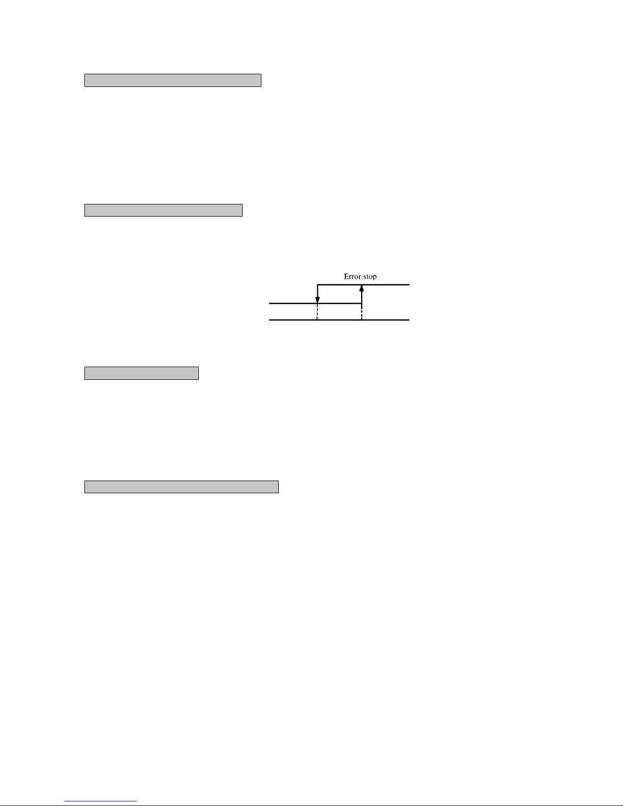
14)
Overload protection during heating
If an overload condition has been detected by the indoor heat exchanger temperature and it has continued for more than 2 seconds
during heating, the compressor is stopped. The compressor is started after a delay of 3 minutes and, if the overload condition is
detected again whithin 60 minutes after the initial detection, the compressor is stopped with the error stop.
Indoor heat exchanger
temperature(˚C)
Heating operation
61
68
15) Automatic restart control
If there is interruption of power while the unit is operating, the unit operates after power restoration under the same condition as
prior to the power interruption. However the compressor will only be able to start three minutes after the power restoration.
Furthermore, if the timer was operating prior to the power interruption, the unit remains stopped even after the restoration of
service.
Note (1) Becomes invalid if the dip switch SW3-1 on the indoor PC board is at OFF (SW3-1 is set at ON when unit is shipped
from the factory).
16)
Thermistor disconnection detection control
a) Detection of indoor return air thermistor disconnection
¡ If there is detection of a disconnection on the return air thermistor in 10 seconds after turning the power ON, the compres-
sor is stopped. If there is a second disconnection on the return air thermistor detected within 60 minutes, there is emergency stop.
Note (1) If the first disconnection on the return air thermistor is detected for a period of 6 continuous minutes, there is emergency
stop. If there is no detection of a second disconnection on the return air thermistor whithin 60 minutes, the first detection
becomes invalid.
b) Detection of heat exchanger thermistor disconnection
¡ If a disconnection is detected on the heat exchanger thermistor in 20 seconds after the compressor has been operating for
2 minutes, the compressor is stopped. If a second disconnection on the heat exchanger thermistor line is detected within
60 minutes, there is emergency stop.
Note (1) If the first disconnection on the heat exchanger thermistor is detected for a period 6 continuous minutes, there is emer-
gency stop.
If there is no detection of second disconnection on the heat exchanger thermistor within 60 minutes, the first detection
becomes invalid.

8
17) Drain detection (Only FDTN(P), FDT, FDR models)
a) If there is detection of a drain abnormality during cooling operation, the drain pump goes ON for 5 minutes and the compres-
sor which had been running comes to a stop.
Overflow detection is carried out at all times with the float switch regardless of operational mode. If an overflow is generated
(or if the float switch is not yet connected or has been disconnected). there is emergency stop (while the Check lamp (yellow)
blinks 4 times) the drain motor operates until reset of the float switch.
b) If a drain abnormality is detected during cooling operation, there is emergency stop (while the Check lamp (yellow) blinks 4
times) to stop the compressor, and the drain pump is operated with the drain motor until reset of the float switch.
c) If a drain abnormality is detected during a stop state or fan operation, there is forced operation of the drain pump for 5
minutes. After 5 minutes have elapsed, the drain motor stops if the float switch is reset. Otherwise, there is emergency stop
(wile the Check lamp (yellow) blinks 4 times) and the drain motor operates until the float switch is reset.
d) If the float switch is not connected or if there is a disconnection, there is emergency stop.
18)
Low voltage guard control
If the power source voltage remains at a value of 80% of rating or less for 3 continuous minutes during operation of the compressor,
the compressor stops (52C OFF). Furthermore, if the power source voltage remains at a figure of 15% of rating or greater after 3
minutes have elapsed since stopping the compressor, there is restarting of the compressor (52C ON). Moreover, during stoppage of
the compressor, the Run lamp (green) blinks 2 times.
Note (1) When starting the compressor for the first time after turning the operational switch ON, there is starting regardless
of the power source voltage. Furthermore, if dip switch SW 3-2 on the internal substrate is OFF, this becomes
invalid. (Switch SW 3-2 is set to ON upon shipment from the factory).
19) Refrigerant shortage error
When 52C is ON when operating in cooling (including automatic cooling), if heat exchanger sensor temperature for the indoor
unit (ThI -R) does not drop to 25 °C or less for 40 minutes 5 minutes or more after the start of operation, an abnormal stop due to
insufficient refrigerant is performed.
20)
External control (remote display)/control of input signal
¡ External control (remote display) output
Following output connectors (CNT) are provided on the control circuit board of indoor unit.
¡ Operation output: Power to engage DC 12V relay (provided by the customer) is outputted during operation.
¡ Heating output: Power to engage DC 12V relay (provided by the customer) is outputted during the heating operation.
¡ Compressor ON output: Power to engage DC 12V relay (provided by the customer) is outputted while the compressor is
operating.
¡ Error output: When any error occurs, the power to engage DC 12V relay (provided by the customer) is outputted.
¡ Control of input signal
(Make sure to connect the standard remote control unit. Control of input signal is not available without the standard remote
control unit.)
Control of input signal (switch input, timer input) connectors (CNT) are provided on the control circuit board of the indoor
unit.
However, when the operation of air conditioner is under the Center Mode, the remote control by CnT is invalid.
9
OFF OFF OFF
OFF OFF
ON
ON ON ON
ON ON
Remote controller
operation OFF
(Last operation has priority.)
Remote controller
operation ON
OFF OFF OFF
ON ON
ON
ON ON
OFF OFF OFF
ON
Remote controller
operation OFF
(Last operation has priority.)
Remote controller
operation ON
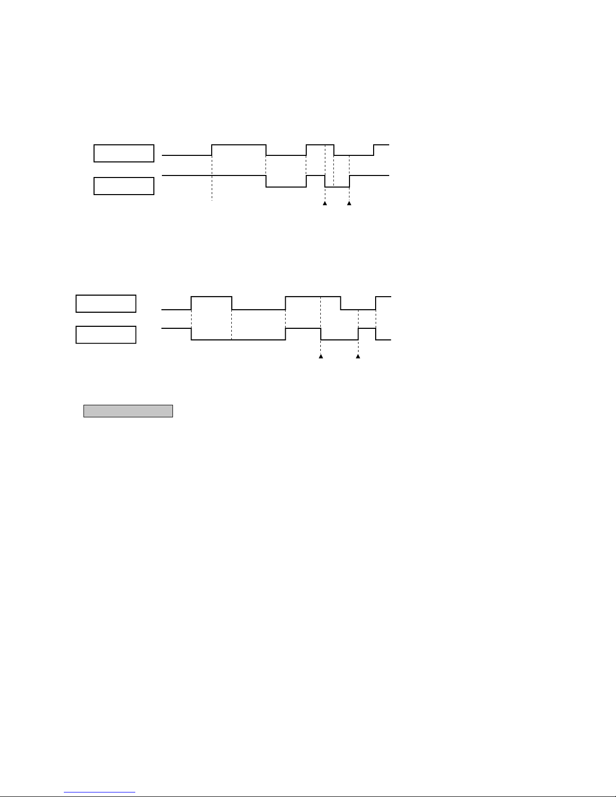
¡ At shipping from factory [FDTN (P), FDEN (P), FDKN (P) models : J3 (SW5-3), FDT, FDR, FDU, FDFL models : J5 (SW5-2) ]
on PCB OFF]
¡ Input signal to CnT OFF → ON [Edge input] ... Air conditioner ON
¡ Input signal to CnT ON → OFF [Edge input] ... Air conditioner OFF
¡ When J3 (SW5-3) [FDTN (P), FDEN (P), FDKN (P) models] or J5 (SW5-2) [FDT, FDR, FDU, FDFL models] on the PCB of
indoor unit is turned on at the field.
Input signal to CnT becomes Valid at OFF Æ ON only and the motion of air conditioner [ON/OFF] is inverted.
CnT input
Unit A
CnT input
Unit A
21) Auto Swing Control (Excepted FDR, FDU, FDFL models)
¡ Have a louver motor to move the louvers up and down for the so called “auto swing” function.
¡ The louver auto swing starts when the AUTO SWING key is pressed once and stops when the AUTO SWING key is pressed
again. The louver position is displayed on the LCD on the remote controller. During auto swing, the position displayed on the
LCD changes, but the positions of the louvers and the display are not coordinated. (The louvers swing 3 - 4 times per minute but
the display changes once per second.)
¡ Stopping the louvers
When the AUTO SWING key is pressed to stop the louver movement, the LCD louver-position display stops and the louvers
stop when they come to the position displayed on the LCD. There are four louver stop position on the LCD. (When jumper wire
J7 [FDTN (P), FDEN (P) models] or J3 [FDT model] on the indoor unit printed circuit board is cut, the louvers stop immediately
at the AUTO SWING key is pressed to stop them and the LCD display changes to show this position. (Excepted FDKN (P)
model)
¡ Movement of louver when the power supply to the controller controlling 4 positions of the louver is switched
on. (Only FDT model)
When power supply is switched on, the louver will automatically swing about 2 times (without operating remote controller).
This is an action for the microcomputer to confirm the louver position in order to input the cycle of the louver motor (LM) to the
microcomputer with the limit switch (LS) pushing the louver motor (LM). If the LS action is not input to the microcomputer,
the louver will stop within 1 minute after the power supply is switched on and will not move from then on.
 Loading...