

Mitsubishi Heavy Industries eco touch RC-EX1A, eco touch RC-EX1N Installation Manual
eco touch REMOTE CONTROL
RC-EX1A/RC-EX1N
INSTALLATION MANUAL
PJZ 01 2D0 77
B

— 1 —
Contents
1.Safety Precautions …………………2
2. Accessories & Prepare on site ……4
3. Remote control installation
procedure …………………………… 4
Determine where to install the remote control .. 4
Installation procedure …………………………… 5
Main/Sub setting when more than one remote
controls are used ………………………………… 7
4. Functions and menu items of
Remote control ………………………9
5. The indication when power source
is supplied ………………………… 13
6. Installation settings ……………… 15
7. R/C function settings …………… 20
8. IU settings ………………………… 26
9. Service & Maintenance ………… 38
10. Select the Language …………… 46
— 2 —
— 3 —
1 . Safety Precautions
This installation manual describes the installation methods and precautions related to the remote control. Use this
manual together with the user’s manuals for the indoor unit, outdoor unit and other optional equipment. Please read
this manual carefully before starting the installation work to install the unit properly.
Safety precautions
●
Please read this manual carefully before starting installation work to install the unit properly.
Every one of the followings is important information to be observed strictly.
WARNING
Failure to follow these instructions properly may result in serious consequences such as
death, severe injury, etc..
CAUTION
Failure to follow these instructions properly may cause injury or property damage.
It could have serious consequences depending on the circumstances.
●
The following pictograms are used in the text.
Never do. Always follow the instructions given.
●
Keep this manual at a safe place where you can consult with whenever necessary. Show this manual to installers
when moving or repairing the unit. When the ownership of the unit is transferred, the “Installation Manual”
should be given to a new owner.
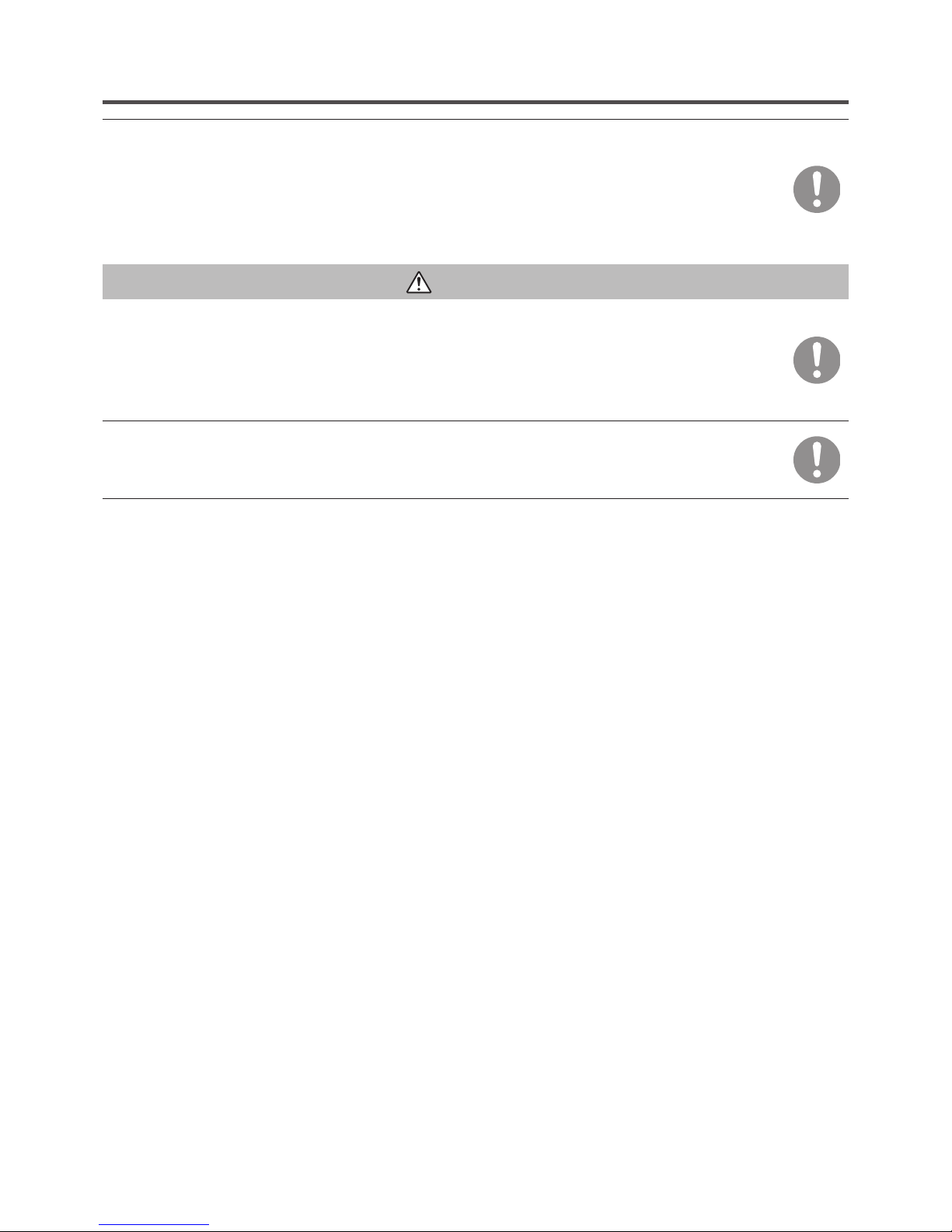
WARNING
Ask a professional contractor to carry out installation work according to the installation manual.
Improper installation work may result in electric shocks, fire or break-down.
Shut OFF the main power supply before starting electrical work.
Otherwise, it could result in electric shocks, break-down or malfunction.
Do not install the unit in appropriate environment or where inflammable gas could generate, flow
in, accumulate or leak.
If the unit is used at places where air contains dense oil mist, steam, organic solvent vapor, corrosive
gas (ammonium, sulfuric compound, acid, etc) or where acidic or alkaline solution, special spray, etc.
are used, it could cause electric shocks, break-down, smoke or fire as a result of significant
deterioration of its performance or corrosion.
Do not install the unit where water vapor is generated excessively or condensation occurs.
It could cause electric shocks, fire or break-down.
Use the specified cables for wiring, and connect them securely with care to protect electronic
parts from external forces.
Improper connections or fixing could cause heat generation, fire, etc.
Seal the inlet hole for remote control cable with putty.
If dew, water, insect, etc. enters through the hole, it could cause electric shocks, fire or break-down.
— 3 —
When installing the unit at a hospital, telecommunication facility, etc., take measures to suppress
electric noises.
It could cause malfunction or break-down due to hazardous effects on the inverter, private power
generator, high frequency medical equipment, radio communication equipment, etc.
The influences transmitted from the remote control to medical or communication equipment could
disrupt medical activities, video broadcasting or cause noise interference.
CAUTION
Do not install the remote control at following places.
It could cause break-down or deformation of remote control.
(1) Where it is exposed to direct sunlight
(2) Near the equipment to generate heat
(3) Where the surface is not flat
Do not leave the remote control with its upper case removed.
When the upper case is removed, put it in a packing box or packing bag to protect internal PCBs or
other parts from dust, moisture, etc.
— 4 —
— 5 —
2 . Accessories & Prepare on site
Item name Q’ty Remark
Switch box
For 1 piece or 2 pieces (JIS C8340 or
equivalent)
1
These are not required when installing
directly on a wall.Thin wall steel pipe for electric appliance
(JIS C8305 or equivalent)
As required
Lock nut, bushing (JIS C8330 or equivalent)
As required
Lacing (JIS C8425 or equivalent)
As required
Necessary to run R/C cable on the wall.
Putty Suitably For sealing gaps
Molly anchor
As required
R/C cable (0.3 mm2 x 2 pcs)
As required
See right table when longer than 100 m
Accessories
R/C main unit, wood screw (ø3.5 x 16) 2 pcs
User’s Manual, Installation Manual
Parts procured at site
When the cable length is longer than
100 m, the max size for wires used
in the R/C case is 0.5 mm
2
. Connect
them to wires of larger size near
the outside of R/C. When wires are
connected, take measures to prevent
water, etc. from entering inside.
< 200 m 0.5 mm2 x 2-core
< 300 m 0.75 mm
2
x 2-core
< 400 m 1.25 mm
2
x 2-core
< 600 m 2.0 mm
2
x 2-core
3. Remote control installation procedure
Determine where to install the remote control
Installation “Using a switch box”
“Installed directly on a wall”
Wiring direction “Backward”
“Upper center”, “Upper left”
Cautions for selecting installation place
(1) Installation surface must be flat and sufficiently strong.
R/C case must not be deformed.
(2) Where the R/C can detect room temperatures accurately.
This is a must when detecting room temperatures with
the temperature sensor of R/C.
· Install the R/C where it can detect the average temperature in the room.
· Install the R/C separated from a heat source sufficiently.
· Install the R/C where it will not be influenced by the
turbulence of air when the door is opened or closed.
Select a place where the R/C is not exposed to direct
sunlight or blown by winds from the air conditioner or
temperatures on the wall surface will not deviate largely
from actual room temperature.
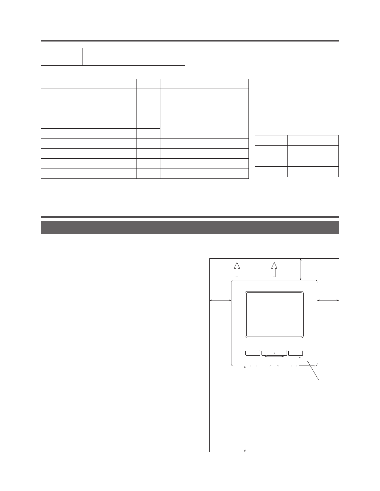
Installation space
30mm
30mm
30mm
120mm
R/C temperature sensor
Wiring
Secure minimum spaces for
disassembling the case.
Upper left and Upper right sides
……30mm or more
Bottom side…120mm or more
If using L-shaped
screwdriver, 50mm or
more is available.
— 5 —
Request
Be sure not to install R/C at a place where temperatures around the installation surface of R/C may differ largely from
actual room temperature.
Difference between detected temperature and actual room temperature could cause troubles.
The correction for detected temperature by the R/C cannot offset such temperature difference because it corrects the
detected temperatures itself.
Request
Do not install the R/C at a place where it is exposed to direct sunlight or where surrounding air temperature exceeds 40°C
or drops below 0°C.
It could cause discoloration, deformation, malfunction or breakdown.
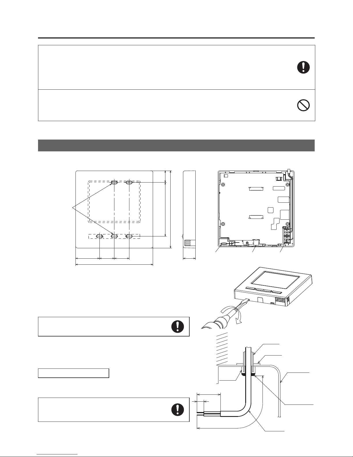
Installation procedure
Dimensions (Viewed from front)
Take care to protect the removed upper case
from moisture or dust.
PCB side (Viewed from rear)
①
To remove the upper case from the bottom cases of R/C
· Insert the tip of flat head screwdriver or the like in the
recess at the lower part of R/C and twist it lightly to
remove.
②
Connect wires from X and Y terminals of R/C to X and Y
terminals of indoor unit.
R/C wires (X, Y) have no polarity.
In case of embedding wiring
(When the wiring is retrieved “Backward”)
③
Embed the switch box and the R/C wires beforehand.
Seal the inlet hole for the R/C wiring with putty.
●
If dust or insect enters, it could cause electric shocks,
fire or breakdown.
8
50
200
Wall
Conduit
Locknut
Switch box
Seal with putty
R/C cable
Bushing
Sensor
USB port
Terminal Block
37 23 23
Fixing holes
18.383.5
120
19
120
— 6 —
— 7 —
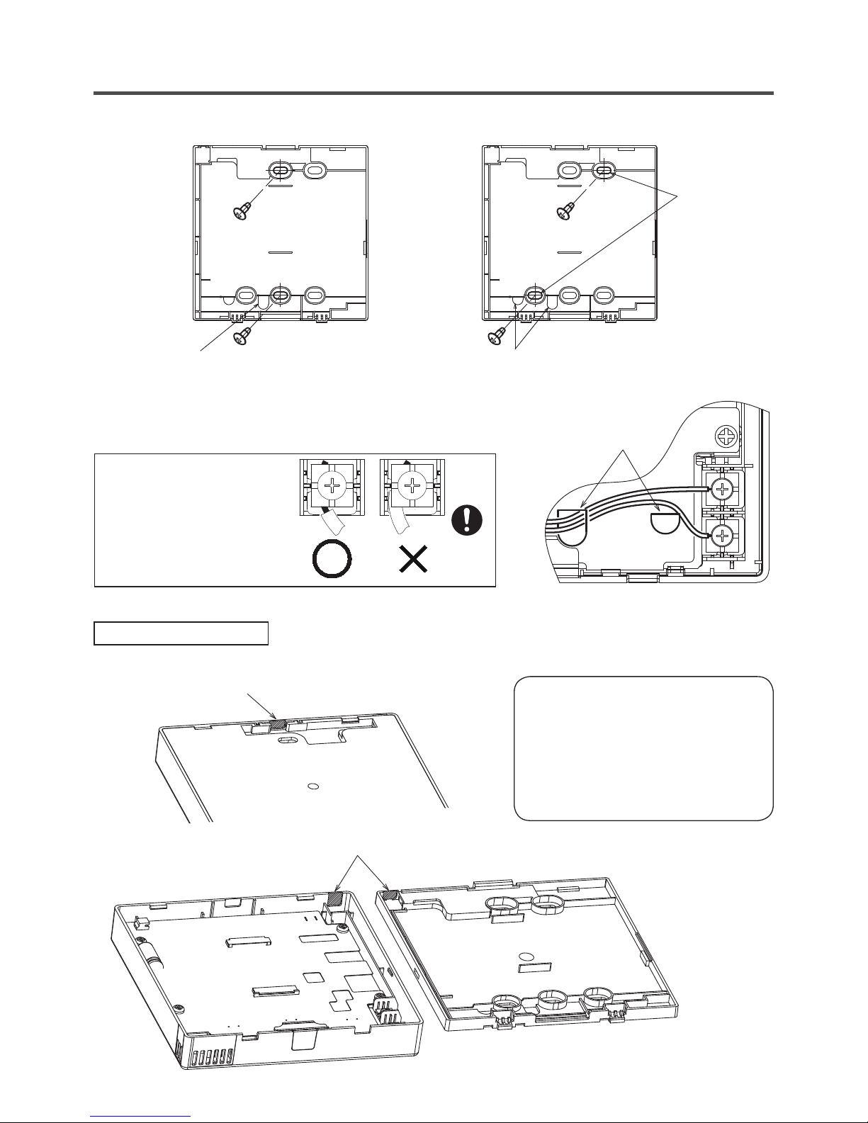
④
When wires are passed through the bottom case, fix the bottom case at 2 places on the switch box.
Switch box
for 1 pc
Switch box
for 2 pcs
Wire outlet
Downside
Upper side
Bottom case
Downside
Upper side
Bottom case
Wire outlet
Cut out the thin
wall part at the
screw mounting
section with a
knife or the like
before tightening
the screw.
Downside
Upper side
Bottom case
Wire outlet
Cut out the thin
wall part at the
screw mounting
section with a
knife or the like
before tightening
the screw.
⑤
When fixing the bottom case diagonally at 2 places, cut out the
thin wall section on the case.
⑥
Fix wires such that the wires will run around the terminal screws
on the top case of R/C.
⑦
Install the upper case with care not to pinch wires of R/C.
8
50
200
Wall
Conduit
Locknut
Switch box
Seal with putty
R/C cable
Wiring hole on bottom case
Bushing
In case of exposing wiring
(When the wiring is taken out from the “upper center” or “upper left” of R/C)
③
Cut out the thin wall sections on the cases for the size of wire.
Upper center
Upper left
Upper case
Bottom case
When taking the wiring out from the upper center,
open a hole before separating the upper and
bottom cases. This will reduce risk of damaging
the PCB and facilitate subsequent work.
When taking the wiring out from the upper left,
take care not to damage the PCB and not to
leave any chips of cut thin wall inside.
Cautions for wire connection
Use wires of no larger than 0.5 mm2 for
wiring running through the remote
control case, Take care not to pinch
the sheath.
Tighten by hand (0.7 N·m or less)
the wire connection. If the wire is
connected using an electric driver, it
may cause failure or deformation.
— 7 —
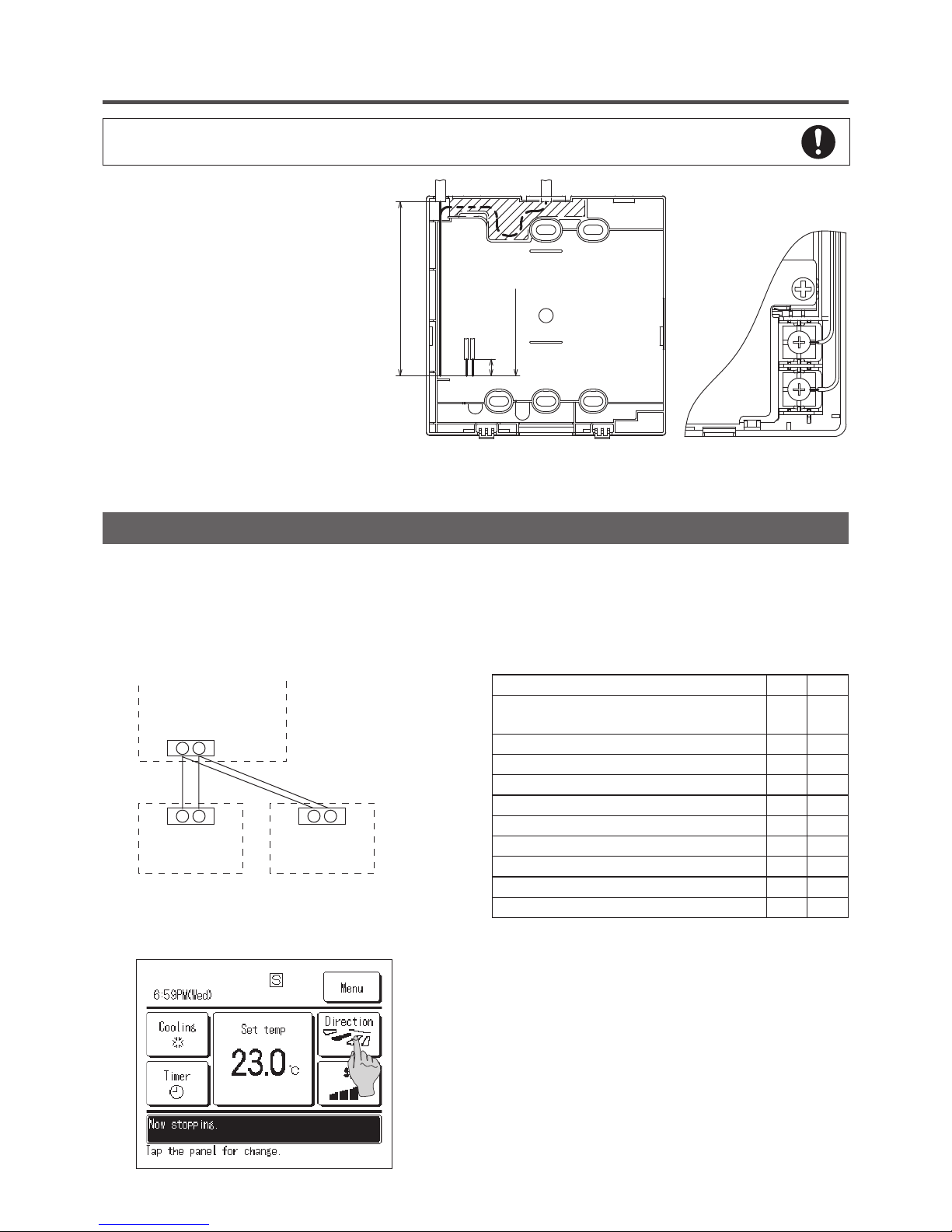
If the hole is cut too large, moisture, dust or insects may enter.
Seal gaps with putty or the like.
④
Fix the bottom R/C case on a
flat surface with wood screws.
⑤
In case of the upper center,
pass the wiring behind the
bottom case. (Hatched section)
⑥
Fix wires such that the wires
will run around the terminal
screw of the top case of R/C.
⑦
Install the top case with care
not to pinch wires of R/C.
120mm
(for retrieving
wire from
upper left)
8
190mm
(for retrieving wire
from upper center)
Main-Sub setting for use of two or more R/C
Up to two units of R/C can be used at the maximum for 1 indoor unit or 1 group.
One is main R/C and the other is sub R/C.
Operating range is different depending on the main or sub R/C.
R/C function Main Sub
Run/Stop, setting temperature, fan speed and flap
direction operations
○ ○
High power and energy-saving operations
○ ○
Energy-saving setting
○ -
R/C sensor
○ -
Test run menu operation
○ -
Room temperature range setting
○ -
Indoor unit settings
○ -
Individual flap control
○ -
Operation data display
○ -
Error history display
○ ○
Indoor unit
R/C cable (No polarity)
R/C
“Main”
R/C
“Sub”
X Y
X Y
X Y
Set the “Main” and “Sub” as described at Section 7.
Main/Sub setting when more than one remote control are used
— 8 —
— 9 —
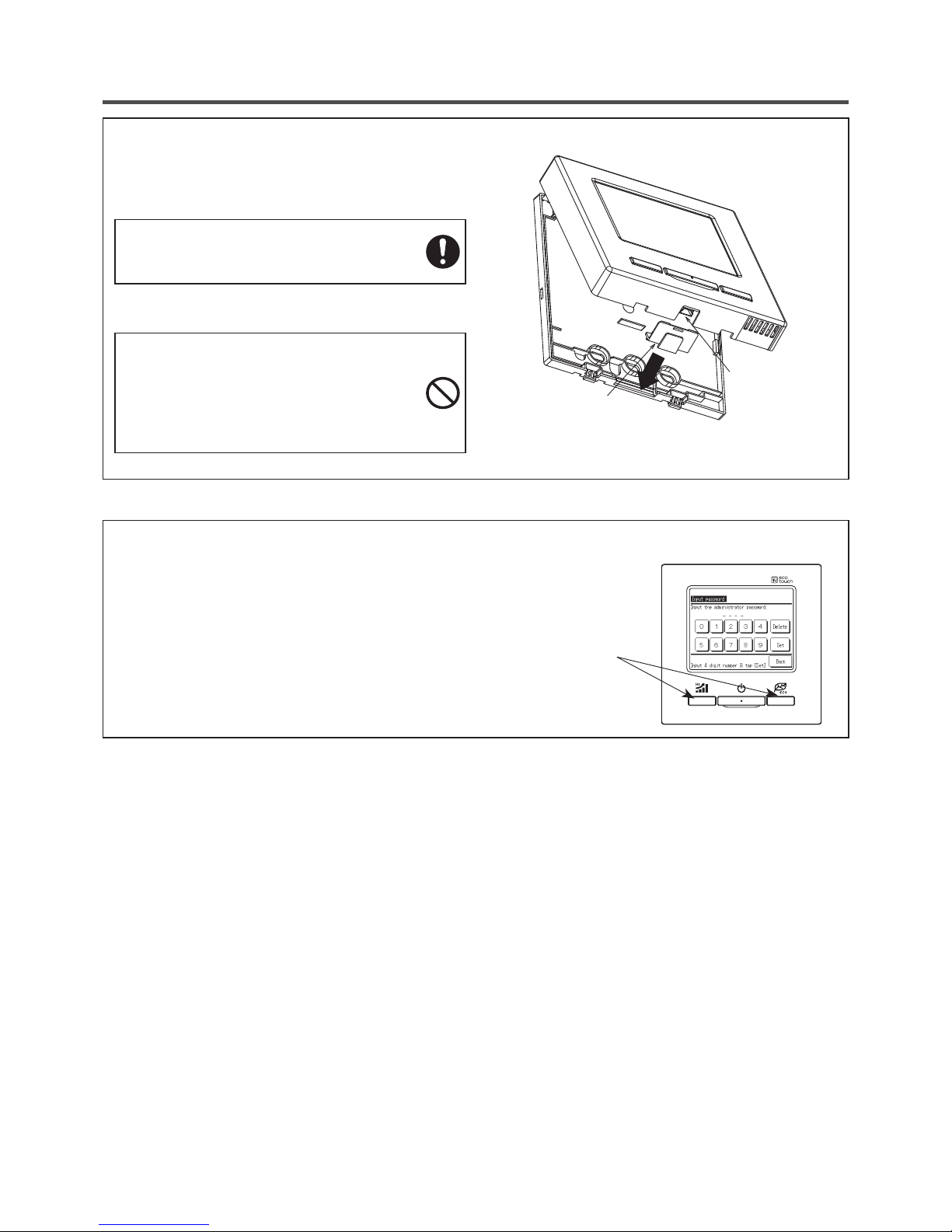
Note: Connection to personal computer
It can be set from a personal computer via the USB port (mini-B).
Connect after removing the cover for USB port of upper case.
Replace the cover after use.
If dust, insect, etc. enters, it could cause electric
shocks or breakdown.
Special software is necessary for the connection.
For details, view the web site or refer to the engineering data.
Do not connect to a personal computer
without using the special software.
Do not connect the personal computer to the USB
simultaneously with other USB devices.
It could cause malfunction or breakdown of R/C or
personal computer.
USB port
Cover
Note: Initializing of password
Administrator password (for daily setting items) and service password (for installation, test
run and maintenance) are used.
○
The administrator password at factory default is “0000”. This setting can be changed
(Refer to User's Manual). When the administrator password is forgotten, it can be
initialized, if the [Highpower] and the [Energy-saving] buttons are pushed simultaneously
for 5 seconds on the administrator password input screen.
○
Service password is “9999”, which cannot be changed.
When the administrator password is input, the service password is also accepted.

— 9 —
①
switch
One push on the button starts operation and
another push stops operation. (★)
②
switch
Pushing this button starts the high-power operation.
(★)
③
switch
Pushing this button starts the energy-saving
operation. (★)
④
Operation lamp
This lamp lights in green (yellow-green) during
operation. It changes to red if any error occurs.
⑤
LCD (With backlight)
A touch on the LCD lights the backlight.
The backlight turns off automatically if there is no
operation for certain period of time.
Duration of the backlight lighting can be changed.
(★)
When the backlight is setting ON, if the screen is
tapped while the backlight is turned off, the
backlight only is turned on. (Operations of switches
①, ②
and ③ are excluded.)
⑥
USB port
USB connector (mini-B) allows connecting to a
personal computer.
For operating methods, refer to the User's manual
attached to the software for personal computer
(Utility software of Eco-touch remote control RCEX1 series)
★
See User's manual for details.
Touch panel system, which is operated by tapping the LCD screen with a finger, is employed for any operations
other than the
①
Run/Stop, ② High power and ③ Energy-saving switches.
⑤
LCD display (With backlight)
4.
Functions and menu items of Remote control
Names and functions of sections on R/C (Operating section)
③
switch
④
Operation lamp
⑥
USB port (mini-B)
①
switch
②
switch
Request
· When connecting to a personal computer, do not connect
simultaneously with other USB devices.
Please be sure to connect to the computer directly, without
going through a hub, etc.

— 10 —
— 11 —
①
Clock, R/C name display
Displays the current time (★) and the name of R/C
(★)
②
Icon display
Each icon is displayed when one of following
settings is going on.
When the peak-cut timer
is set.
When setting is made
from the sub R/C.
(★)
When the central control
(Optional) is running.
When the periodical
inspection is necessary.
(★)
During the ventilation
operation
(★)
When ”filter sign” is up.
(★)
When the Permission/
Prohibition setting is made.
(★)
When the weekly timer
is set.
(★)
When the paek-cut timer is set.
(★)
③
Menu button
When setting or changing other than the following
④
– ⑧, touch the menu button. When menu items
are displayed, select one and set.
④
Change operation mode button (★)
Displays the operation mode which is selected
currently. Tap this button to change the operation
mode.
⑤
Change set temp button
(★)
Displays the temperature which is set currently.
Tap this button to change the set temperature.
⑥
Flap direction button
(★)
Displays the flap direction which is selected
currently. Tap this button to change the flap direction.
⑦
Fan speed change button
(★)
Displays the fan speed which is selected currently.
Tap this button to change the fan speed.
⑧
Timer button
(★)
Displays simplified contents of the timer which is
set currently.
(When two or more timers are set, a content of the
timer which will be operated immediately after is
displayed.)
Tap this button to set the timer.
⑨
Message display
Operation status of air conditioner and messages
related to R/C operations, etc, are displayed.
★
See User's manual for details.
* All icons are shown for explanation.
①
Clock, R/C name display
④
Change operation
mode button
TOP screen
⑧
Timer button
②
Icon display
③
Menu button
⑤
Change set temp
button
⑥
Change flap
direction button
⑦
Change fan speed
button
⑨
Message display
Names and functions of sections on R/C (Display)
— 11 —
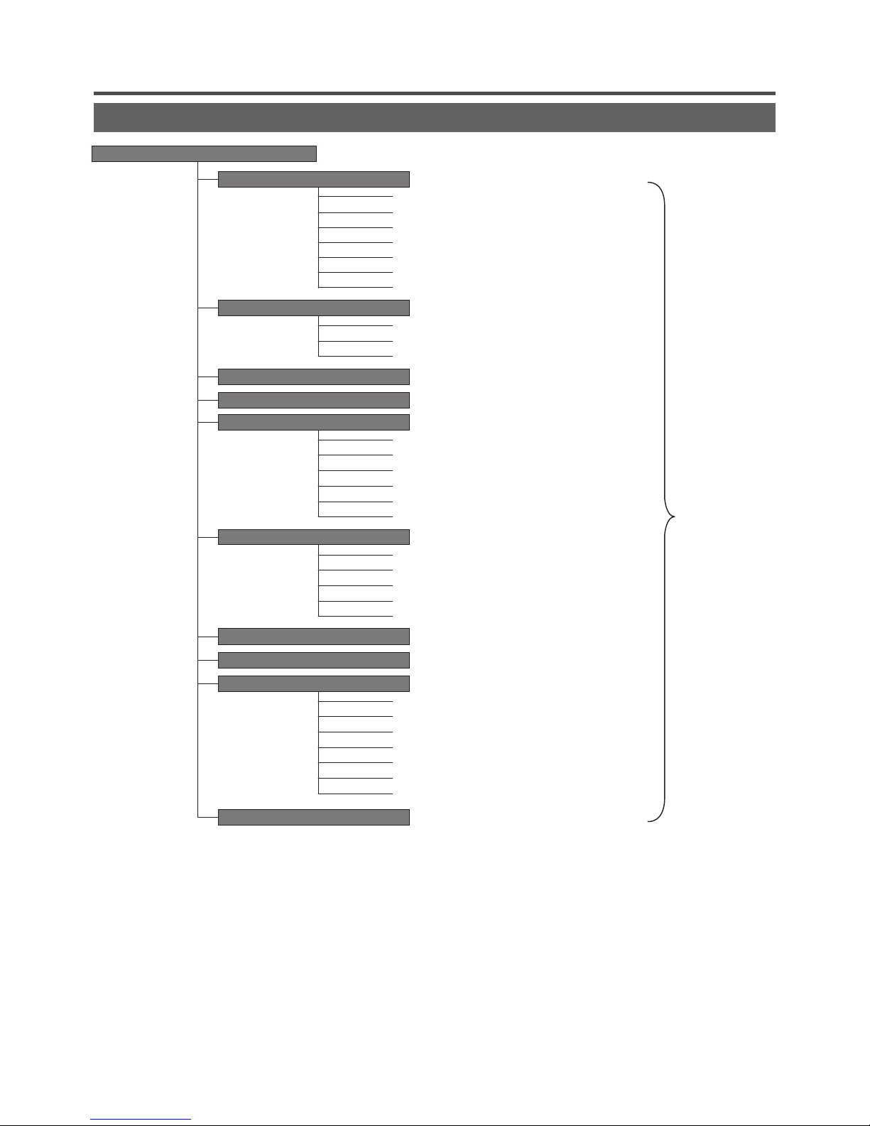
Menu item
Main menu
Basic operation
……………………………………………
Energy-saving setting
……………………………………………
……………………………………………
Ventilation
……………………………………………
……………………………………………
Filter sign reset
Individual ap control
Run/Stop …………………………………
Change operation mode …………………
Change set temp …………………………
Change ap direction ……………………
Change fan speed ………………………
High power operation ……………………
Energy-saving operation…………………
Sleep timer ………………………………
Peak-cut timer ……………………………
Automatic temp set back ………………
Timer
……………………………………………
Set ON timer by hour ……………………
Set OFF timer by hour……………………
Set ON timer by clock ……………………
Set OFF timer by clock …………………
Conrm ……………………………………
Initial setting
……………………………………………
Clock setting ………………………………
Date & time display ………………………
Summer time………………………………
Contrast ……………………………………
Backlight …………………………………
Controller sound …………………………
……………………………………………
Weekly timer
……………………………………………
Home leave mode
Administrator settings
……………………………………………
Permission/prohibition setting …………
Silent mode timer …………………………
Setting temp range ………………………
Temp increment setting …………………
R/C display setting ………………………
Change administrator password ………
Change set temp display ………………
Please refer to
User’s manual
— 12 —
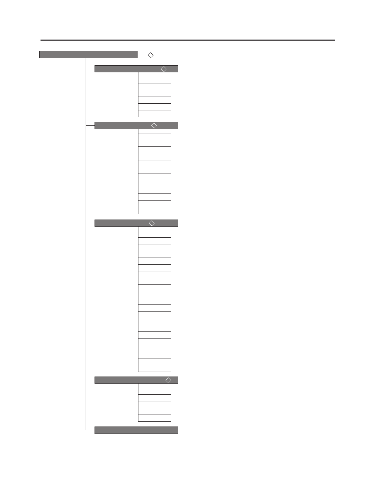
Main menu
R/C settings (◇)
…………………………………………………………………… 20
Main/Sub of R/C ………………………………………………… 21
Return air temp…………………………………………………… 22
R/C sensor ……………………………………………………… 22
R/C sensor adjustment ………………………………………… 22
Operation mode ………………………………………………… 23
˚C / ˚F ……………………………………………………………… 23
Fan speed ………………………………………………………… 23
External input …………………………………………………… 24
Ventilation setting………………………………………………… 24
Flap control ……………………………………………………… 24
Auto-restart ……………………………………………………… 24
Auto temp setting………………………………………………… 25
Auto fan speed …………………………………………………… 25
IU settings (◇)
…………………………………………………………………… 26
High ceiling ……………………………………………………… 28
Filter sign ………………………………………………………… 29
External input 1…………………………………………………… 29
External input 1 signal …………………………………………… 29
External input 2…………………………………………………… 29
External input 2 signal …………………………………………… 29
Heating thermo-OFF temp adjustment ……………………… 30
Return air sensor adjustment…………………………………… 30
Fan control in cooling thermo-OFF …………………………… 30
Fan control in heating thermo-OFF …………………………… 30
Anti-frost temp …………………………………………………… 31
Anti-frost control ………………………………………………… 31
Drain pump operation …………………………………………… 31
Residual fan operation in cooling ……………………………… 31
Residual fan operation in heating ……………………………… 32
Intermittent fan operation in heating…………………………… 32
Fan circulator operation ………………………………………… 32
Control pressure adjust ………………………………………… 32
Auto operation mode …………………………………………… 33
Thermo. rule setting……………………………………………… 36
Auto fan speed control ………………………………………… 37
IU overload alarm………………………………………………… 37
…………………………………………………………………… 38
Service & Maintenance (◇)
IU address ………………………………………………………… 39
Next service date ………………………………………………… 39
Operation data …………………………………………………… 40
Error display ……………………………………………………… 41
Saving IU settings ……………………………………………… 42
Special settings ………………………………………………… 44
…………………………………………………………………… 46
Select the language
Installation settings (◇)
…………………………………………………………………… 15
Installation date ………………………………………………… 16
Company information …………………………………………… 16
Test run …………………………………………………………… 17
Static pressure adjustment …………………………………… 18
Change auto-address …………………………………………… 18
Address setting of main IU ……………………………………… 18
IU back-up function ……………………………………………… 19
(
◇
) It is necessary to input the Service password for menu items showing.
— 13 —
[Main]
③
⇒④⇒
⑤
[Sub]
①
⇒⑥⇒
⑤
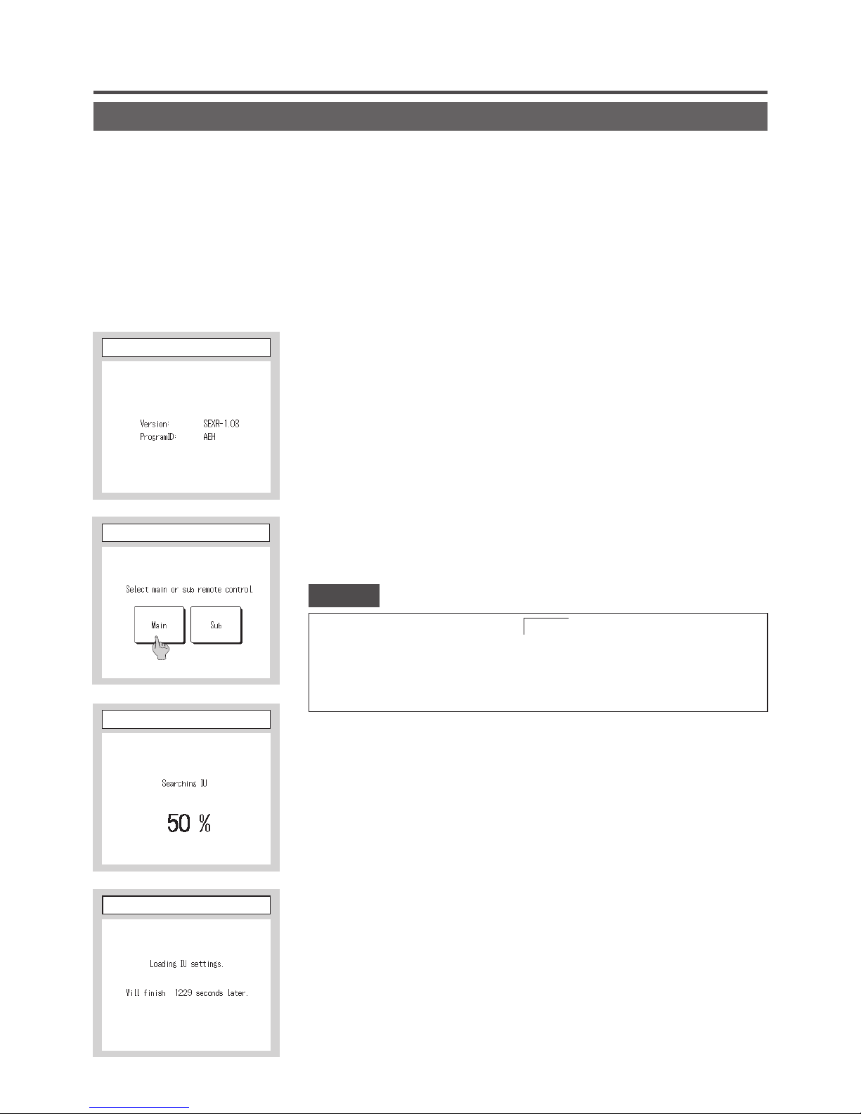
5.
The indication when power source is supplied
Power on and initial setting
Power on and initial setting
Set the main and sub R/C units according to the display at the power on.
(1) When the main and sub are not yet set, ①⇒② Main/sub input screen is displayed.
When tapping the [Main] or [Sub] button, initial setting starts.
If any wrong button has been tapped by mistake, the setting can be changed after the end of the initializing
operation.
(2) When the main and sub R/C units have already been set, ⑥ Ackowledge screen to continue setting is displayed.
(3) When using 2 units of RC-EX1 as the main and sub, if the first one is set for the main, the second is set for the
sub automatically.
· When only one unit of R/C is used, tap the
Main
button.
In the state of initial setting, if either one of buttons ([Main]/[Sub]) is not tapped, it keeps the
screen unchanged.
When two R/Cs are used, if either one of them is set for the main, the other is set for sub
automatically.
Caution
①
Start screen
②
Min/sub set input
③
IU search on
④
IU info acquisition on
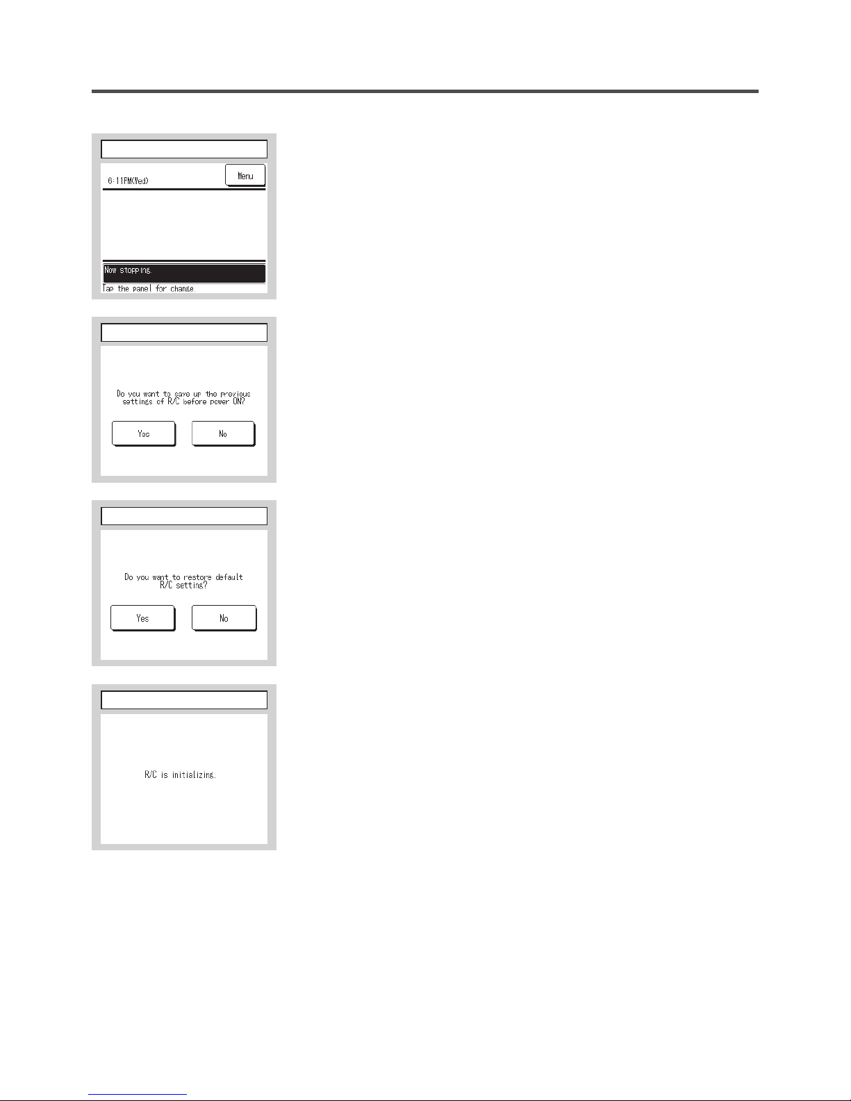
— 14 —
— 15 —
[Yes] Continue ⇒
⑥⇒⑤
[No] Change
⇒
⑦
If the screen is not tapped for more than 15 seconds, the [Yes] (Continue) is
selected and the display changes to the screen of ⑤.
[Yes]
⇒⑧⇒
⑤
[No]
⇒
⑥
After the initializing, it returns to the default state.
⑤
TOP screen
⑥
Set continue acknowledge
⑦
Initialize acknowledge
⑧
Initialize set on
— 15 —
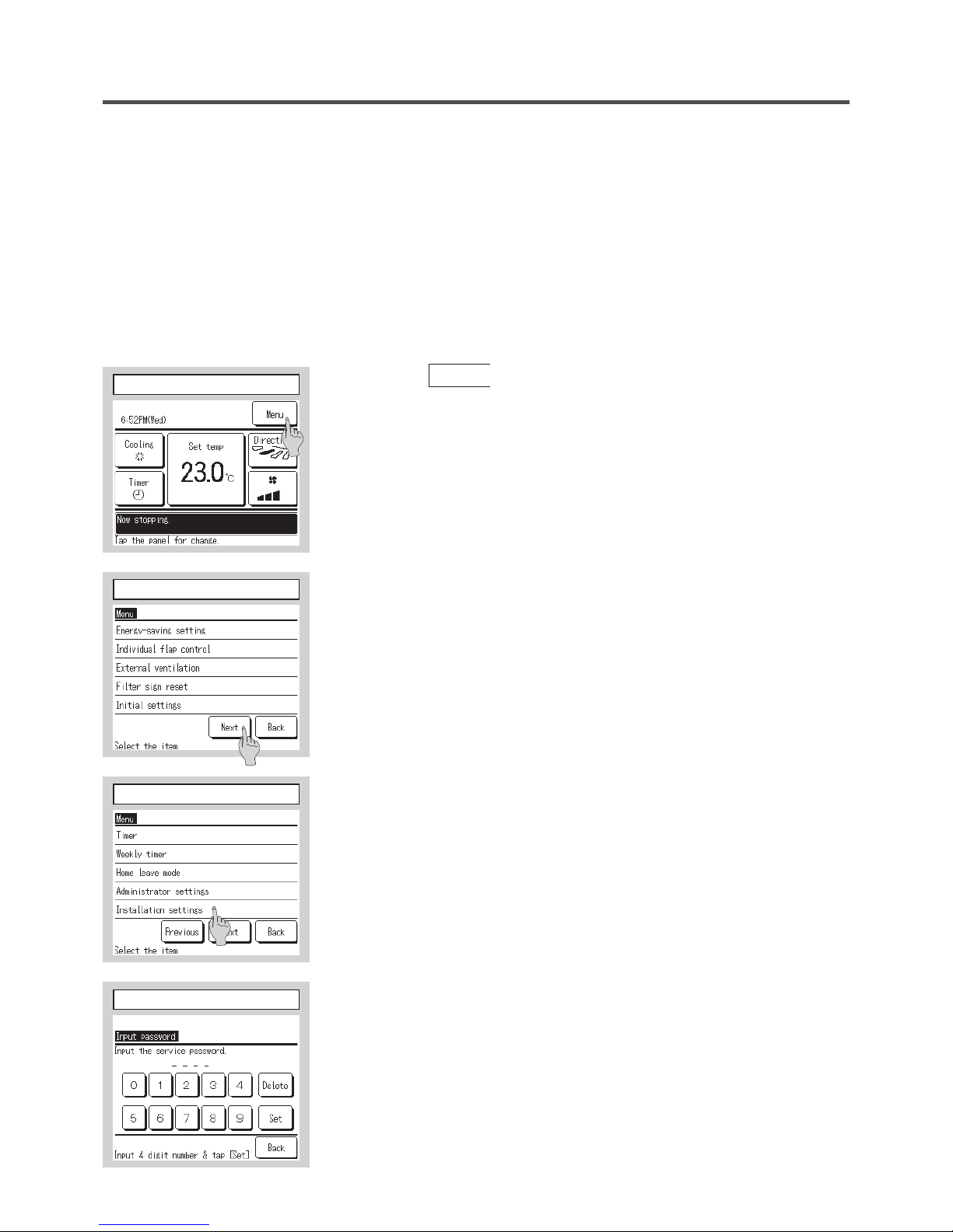
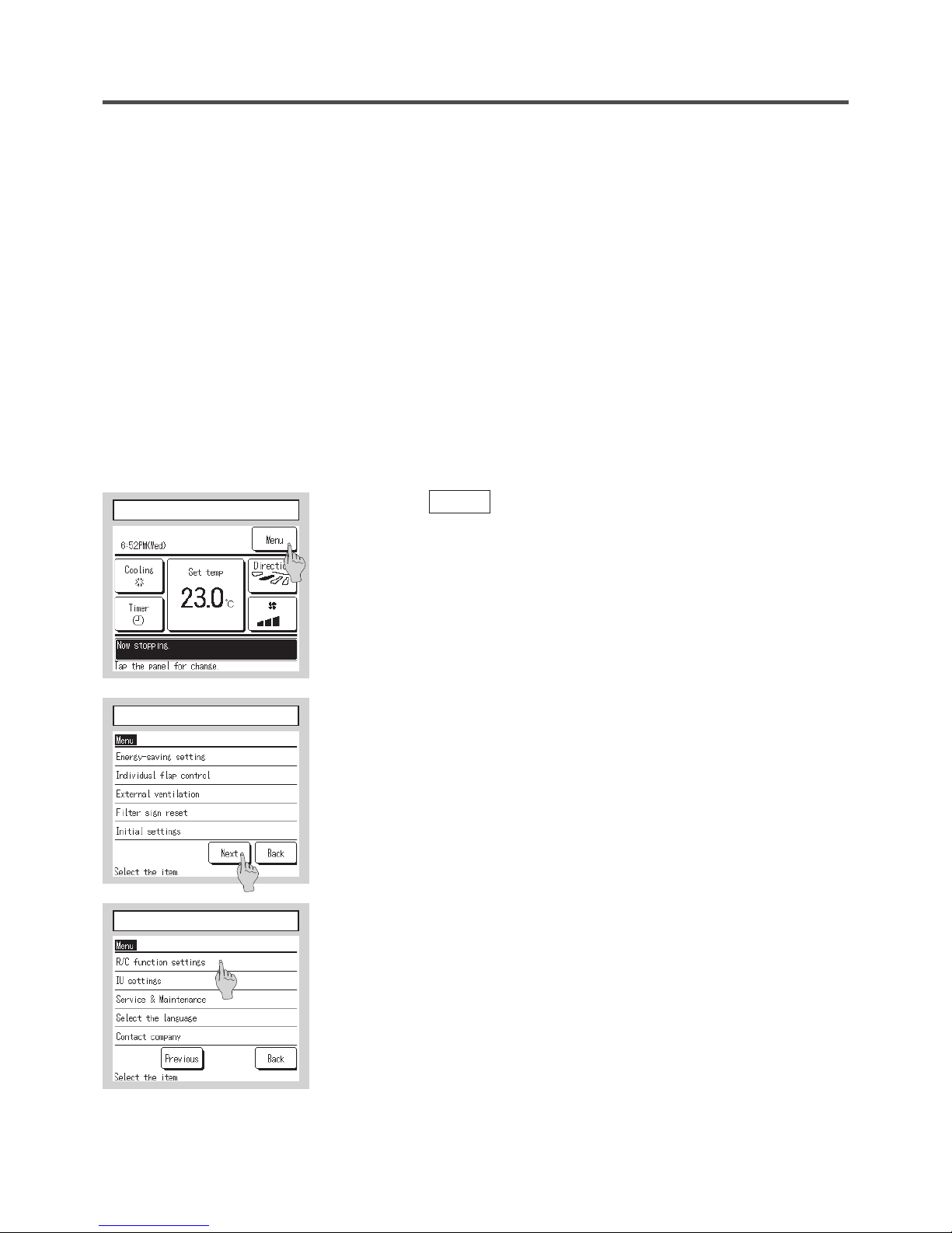
①
Tap the
Menu
button on the TOP screen.
6. Installation settings
Installation settings cover the following items.
(1) Installation date: Register the date when the unit was installed. ➝
⑦
(2) Company information: Enter the information of contact for service. ➝
⑧
(3) Test run: Cooling test run, drain pump test run or compressor Hz fixed operation is performed. ➝
⑪
(4) Static pressure adjustment: Static pressure is adjusted in case of connecting the duct type IU equipped with
the external static pressure adjustment function. ➝
⑮
(5) Change auto-address: In case of the Multi Series (KX) models, the IU address can be changed after the auto-
address setting. ➝
⑯
(6) Address setting of main IU: In case of the Multi Series (KX) models, set the address of main/sub IU to prevent
from mixing operation modes (Cooling, heating). ➝
⑱
(7) IU back-up function: IU rotation, IU capacity back-up, IU fault back-up are set. ➝
⑲
②③
Main menu screen is displayed.
Tap the “Installation settings” button on the menu screen.
④
Display the service password input screen.
Enter the service password (4-digit number).
The service password is “9999”. (Unable to change)
①
TOP screen
②
Menu screen
③
Menu screen #2
④S
ervice password input
— 16 —
— 17 —
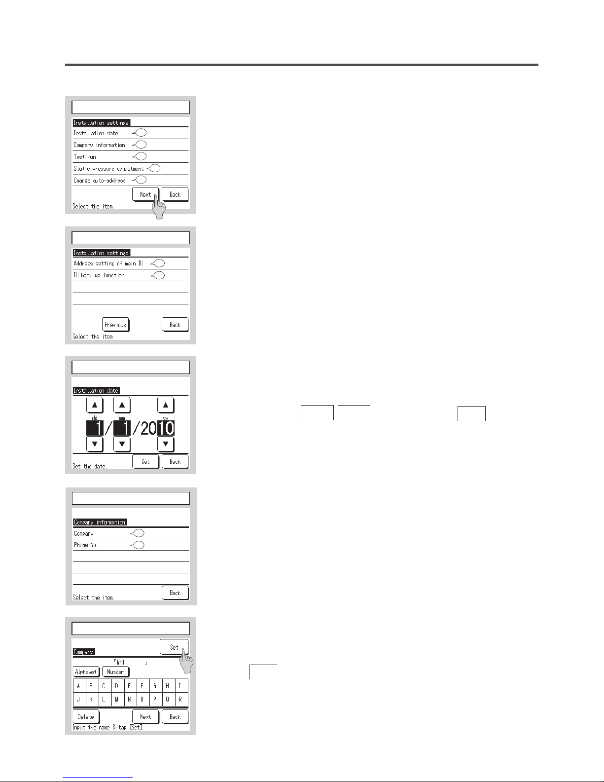
⑤⑥
Display the installation settings screen.
⑦
Installation date
Enter the date when the unit was installed.
Select the date with
▲ ▼
buttons, and tap the
Set
button.
⑤
Installation settings menu
⑦
Installation date
⑥
Installation settings menu
7
8
11
15
16
19
18
⑧
Company information
Enter the company information.
Company ➝
⑨
Phone No. ➝
⑩
⑨
Enter the contact.
Up to 10 1-byte alpha numeric letters can be used.
Tap the
Set
button after the input.
⑧
Company information
9
10
⑨
Enter the contact
— 17 —
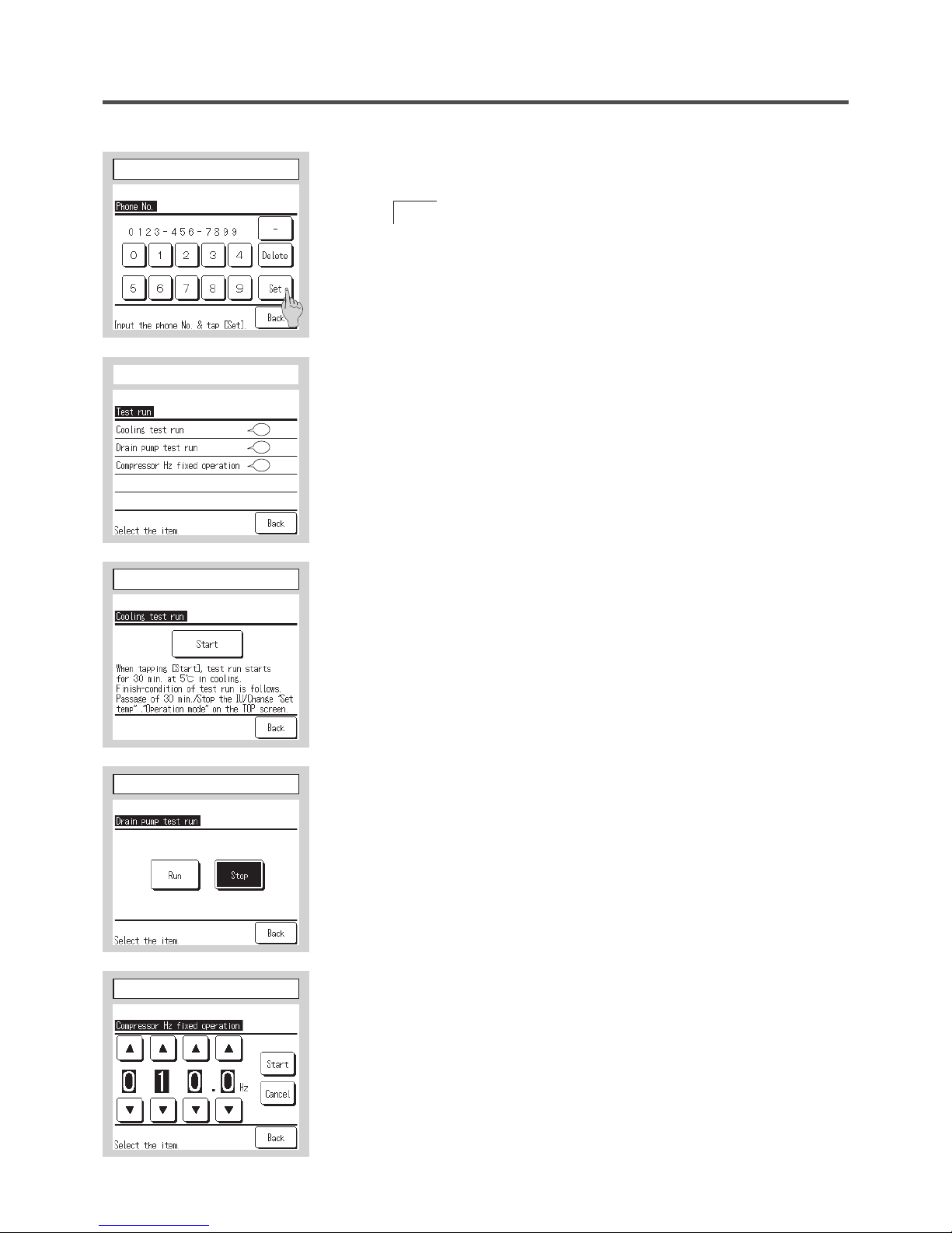
⑩
Enter the Phone No. of the contact.
Tap the
Set
button after the input.
⑪
Test run
Select a test run item to be implemented.
(a) Cooling test run: Operation can be made only in cooling mode. ➝
⑫
(b) Drain pump test run ➝
⑬
(c) Compressor Hz fixed operation: Setting can be made when the unit is
stopped. This operation starts by operation procedure of the unit. ➝
⑭
⑩
Enter the Phone No. of the contact
⑪
Test run
12
13
14
⑫
Cooling test run
When the room temperature is too low to start the cooling test run, it operates
for 30 minutes by decreasing the set temperature to 5°C.
⑬
Drain pump test run
Drain pump can be operated independently.
⑭
Compressor Hz fixed operation
Compressor operation frequency of the inverter outdoor unit can be fixed. It
may not be able to control effectively depending on the outdoor unit models.
⑫
Cooling test run
⑬
Drain pump test run
⑭
Compressor Hz xed operation
— 18 —
— 19 —
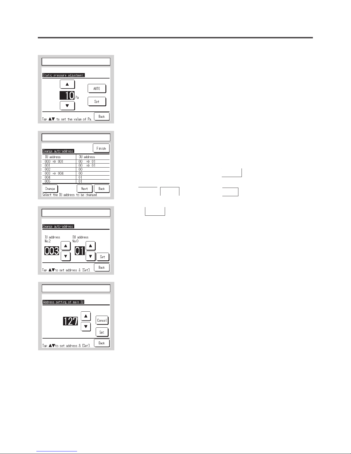
⑮
Static pressure adjustment
This is operable in case of connecting duct type IU equipped with the external
static pressure adjustment function.
Operating method is described in the installation manuals for the indoor units
with this function.
⑮
Static pressure adjustment
⑯⑰
Change auto-address
In case of Multi series (KX) models, the IU addresses registered with the autoaddress setting method can be changed with this function .
When an indoor unit is selected and the
Change
button is tapped, the display
changes to the Change auto-address screen ⑰. When the address is changed
with
▲ ▼
buttons and the
Set
button is tapped, it returns to
the Change auto-address screen ⑯ on which the new address is displayed.
Tap the
Finish
button to register the new address.
⑱
Address setting of main IU
In case of Multi Series (KX) models, it is possible to let indoor units (Sub IUs)
follow the operation mode (Heating, cooling) of the indoor unit (Main IU).
Set the address of the Main IU to the Sub IUs which shall be followed to the
Main IU by using each R/C connected to each Sub IU.
In case of the single PAC unit, or the plural indoor units connected to one R/C,
it is not available to operate.
Setting can be made from the main R/C of Sub IU only. It cannot be set from
the sub R/C of Sub IU.
⑯
Change auto-address
⑰
Change auto-address
⑱
Address setting of main IU
— 19 —
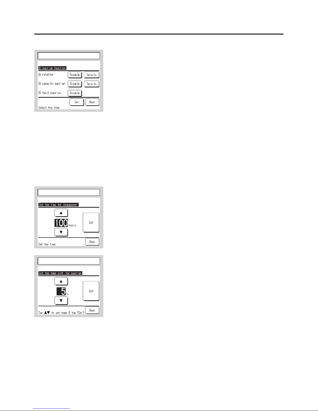
⑲
IU Back-up function
In case of 2 sets of indoor units connected to one R/C, it is available to
perform back-up operation with them.
IU rotation: Operate 2 sets of indoor units alternately at every set time
of operation interval.
Set the timer for changeover ➝
⑳
IU capacity back-up: When the temp difference between the set temp
and the actual room temp is higher than the set temp
diff., 2 sets of indoor units operate. When the temp
difference reaches to the set temp diff. it is switched to
one unit operation.
Set the temp diff. for back-up ➝
IU fault back-up: If one of the IU has a fault and stops, the other one
starts operation.
[Enable/Disable] setting of each function can be done.
When [IU rotation] or [IU capacity beck-up] is set [Enable], [IU fault
back-up] is set [Enable] automatically.
⑳
Set the timer for changeover
In IU rotation function, the timer to changeover the operation of 2
indoor units is set.
Set the temp diff. for back-up
In IU capacity back-up function, the temperature difference between
the temp to start operation of 2 indoor units and the set temp is set.
(Setting range 2-5°C)
⑲
IU Back-up function
⑳
Set the timer for changeover
Set the temp diff. for back-up
— 20 —
— 21 —
7. R/C function settings
R/C function settings cover the following items. These settings can be done only when the unit is stopped.
(1) Main/Sub of R/C: Set the main or sub R/C . ➝
⑧
(2) Return air temp: Set the detection method of return air temp for applying to thermo. rule*. ➝
⑨
(3) R/C sensor: Set the operation mode to apply the temp detected with R/C sensor to thermo. rule*. ➝
⑩
(4) R/C sensor adjustment: Adjust the temperature detected with the R/C sensor. ➝
⑪
(5) Operation mode: Set Enable/Disable for each operation mode. ➝
⑭
(6) °C/°F: Set which of °C or °F is used. ➝
⑮
(7) Fan speed: Changes the fan speed. ➝
⑯
(8)
External input: Set the range to apply the external input (CNT) connected to plural indoor units.
➝
⑰
(9) Ventilation setting: Set this when a ventilation device is connected. ➝
⑱
(10) Flap control: Set one of 4 flap stop positions or free flap stop. ➝
⑲
(11) Auto-restart: Set Enable or Disable of Auto-restart function. ➝
⑳
(12) Auto temp set: Set Enable or Disable of Auto temp set function. ➝
(13) Auto fan speed: Set Enable or Disable of Auto fan speed function. ➝
* “Thermo. rule” means the “Judging to make thermostat ON or OFF” by detecting temperature.
①
Tap the
Menu
button on the TOP screen.
②③
Main menu screen is displayed.
Tap the “R/C function settings” button on the menu screen.
①
TOP screen
②
Menu screen
③
Menu screen #2

— 21 —
④
Display the service password input screen.
Enter the service password (4-digit number).
The service password is “9999”. (Unable to change)
⑤⑥⑦
Display the R/C setting menu screens.
④
Service password input
⑤
R/C setting menu 1
⑥
R/C setting menu 2
⑦
R/C setting menu 3
8
9
10
11
14
20
21
22
15
16
17
18
19
⑧
Main/Sub of R/C
Use this when changing the Main/Sub setting of R/C.
⑧
Main/Sub of R/C
— 22 —
— 23 —
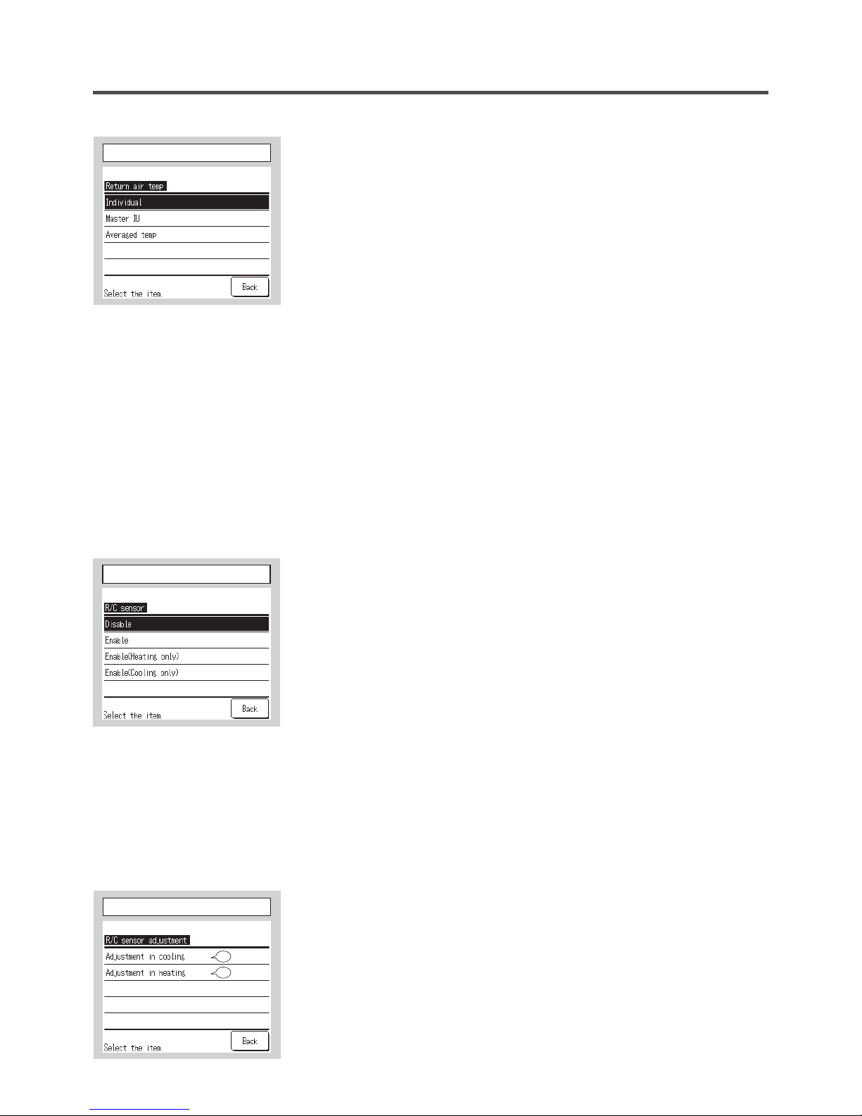
⑨
Return air temp
Thermo. rule* is applied based on the temperature detected with the return air
temp sensor of IU.
When plural indoor units are connected to one R/C, the return air temp applied
to the thermo. rule* can be selected.
Individual: Thermo. rule* is applied based on the return air temp of each IU.
When plural units are connected to one R/C, it is based on the
return air temp of the main unit.
Master IU: Thermo. rule* is applied based on the return air temp of IU having
the youngest address out of IUs connected.
If there are several sets of plural units each of which is connected
to one R/C, it is based on the IU having the youngest address out of
the main units of each plural units.
Averaged temp: Thermo. rule* is applied based on the average of return air
temperatures of IUs connected.
* “Thermo. rule” means the “Judging to make thermostat ON or OFF” by
detecting temperature.
⑩
R/C sensor
Thermo. rule* is applied based on the temp detected with the R/C sensor.
Enable: Thermo. rule* is applied based on the temp detected with the R/C
sensor in all operation modes.
Enable (Heating only): Thermo. rule* is applied based on the temp detected
with the R/C sensor in heating operation only. In case of other
operation modes (including auto-heating mode), it is based on the
Individual control of return air temperature.
Enable (Cooling only): Thermo. rule* is applied based on the temp detected
with the R/C sensor, excepted in heating operation. In case of heating
modes, it is based on the Individual control of return air temperature.
* “Thermo. rule” means the “Judging to make thermostat ON or OFF” by
detecting temperature.
⑩
R/C sensor
⑨
Return air temp
⑪
R/C sensor adjustment
Temperatures detected with the R/C sensor can be adjusted.
Set this within the range of -3 to +3. (At 1°C intervals)
Adjustment in cooling ➝
⑫
Adjustment in heating ➝
⑬
⑪
R/C sensor adjustment
12
13
— 23 —
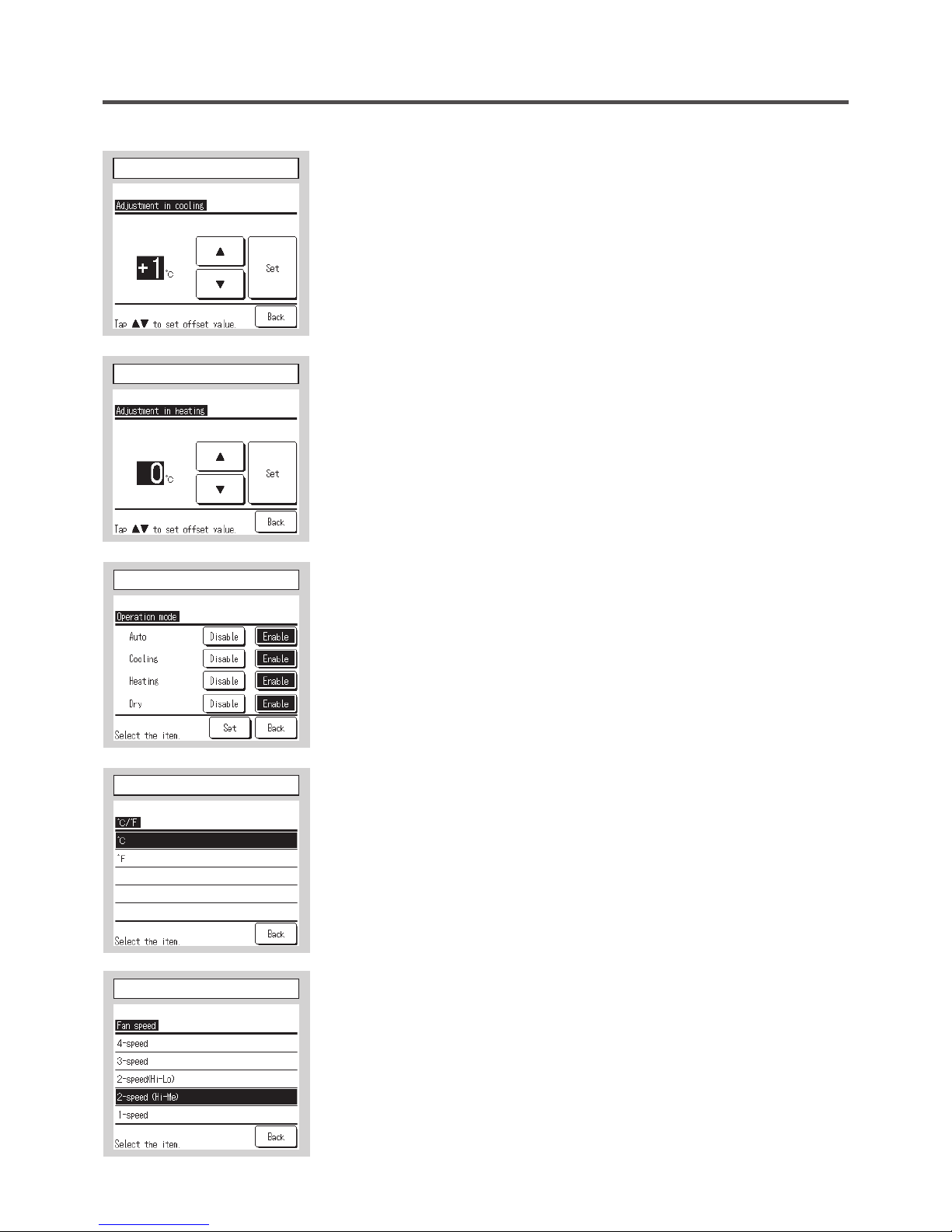
⑫
Adjustment in cooling
⑬
Adjustment in heating
⑭
Operation mode
Enable or Disable can be set for each operation mode.
If the cooling or heating is disabled, the auto is also disabled.
⑫
Adjustment in cooling
⑬
Adjustment in heating
⑭
Operation mode
⑮
°C/°F
Select the unit of temperature displayed on the R/C.
°C: Temperature is displayed in °C.
°F: Temperature is displayed in °F.
⑮
°C/°F
⑯
Fan speed
Fan speed can be changed to the selected one..
It may not be available to select some of fan speeds depending on indoor unit
models.
⑯
Fan speed
— 24 —
— 25 —
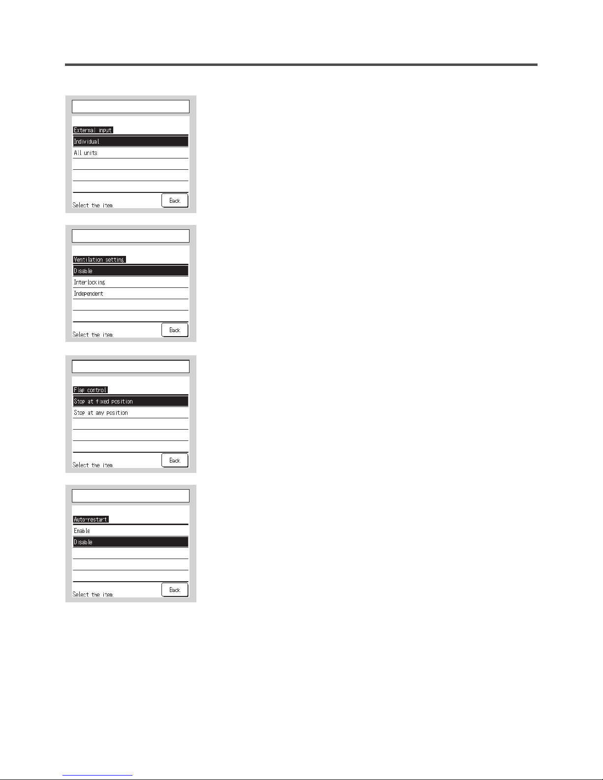
⑰
External input
Set the range to apply the external input received through CNT of either one IU
to plural indoor units connected in one system
Individual: This is applied only to the IU receiving CNT input.
All units: This is applied to all indoor units connected.
⑱
Ventilation setting
Set this when a ventilation device is connected.
Disable: No ventilation device is connected.
Interlocking: Ventilation is interlocked with the Run/Stop of air conditioner.
Independent: If the ventilation is selected from the menu, only the
ventilation device is operated or stopped independently.
⑰
External input
⑱
Ventilation setting
⑲
Flap control
Set the flap stop control.
Stop at fixed position: The flap can be set to stop at one of 4 positions.
Stop at any position: The flap can be set to stop at any position
immediately after operating the R/C switch.
⑳
Auto-restart
Set the state of operation to be started when the power supply is restored
after a power failure.
Enable: It returns to the state before the power failure as soon as the
power supply is restored (After the end of the primary control at
the power on).
Disable: It stops after the restoration of power supply, regardless the state
of operation before the power failure.
⑲
Flap control
⑳
Auto-restart
— 25 —
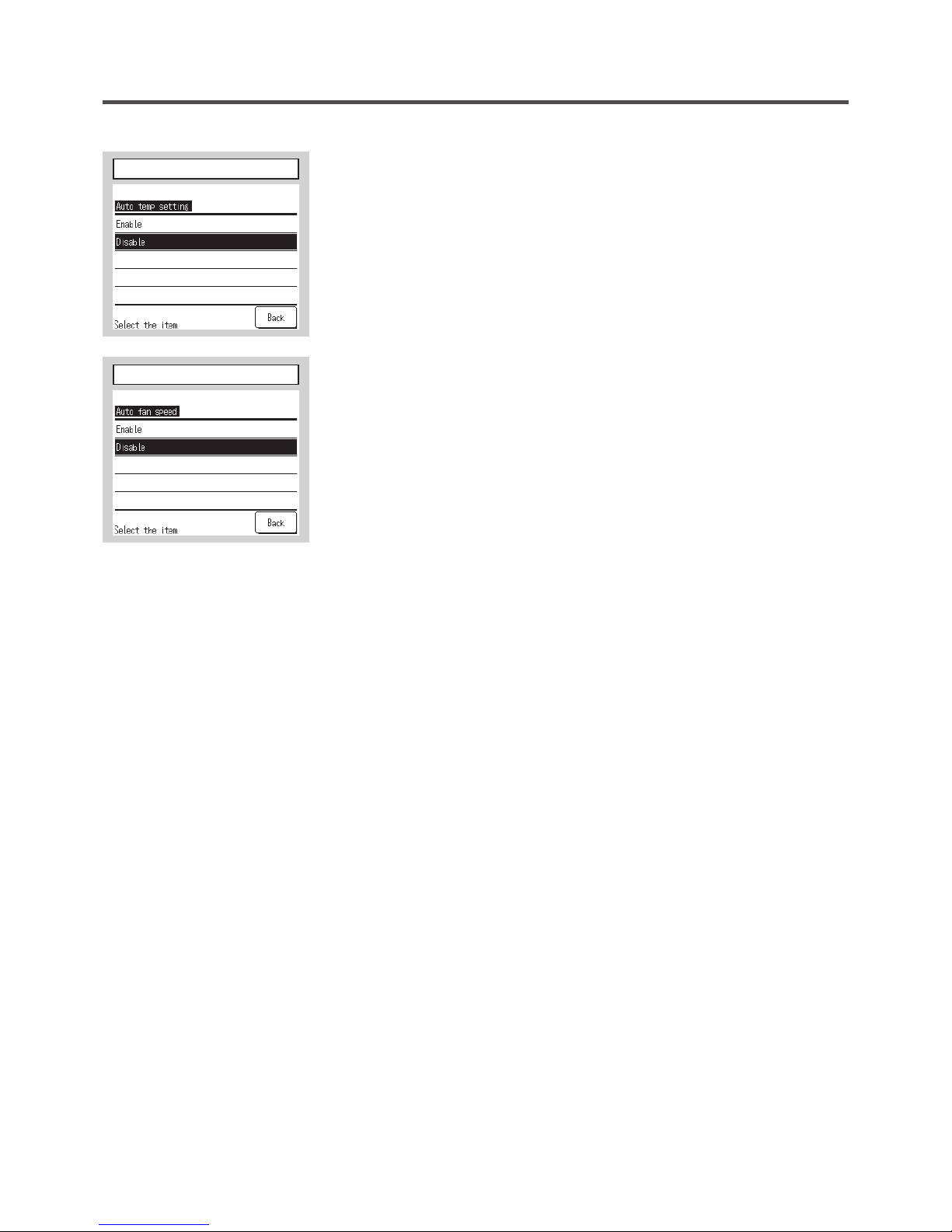
Auto set temp
Select Enable or Disable on the Auto temp setting screen.
Enable: Auto set temp can be selected.
Disable: Auto set temp cannot be selected. No select switch is displayed on
the screen.
Auto fan speed
Select Enable or Disable on the Auto fan speed screen.
Enable: Auto fan speed can be selected.
Disable: Auto fan speed cannot be selected. No select switch is displayed
on the screen.
Auto set temp
Auto fan speed
— 26 —
— 27 —
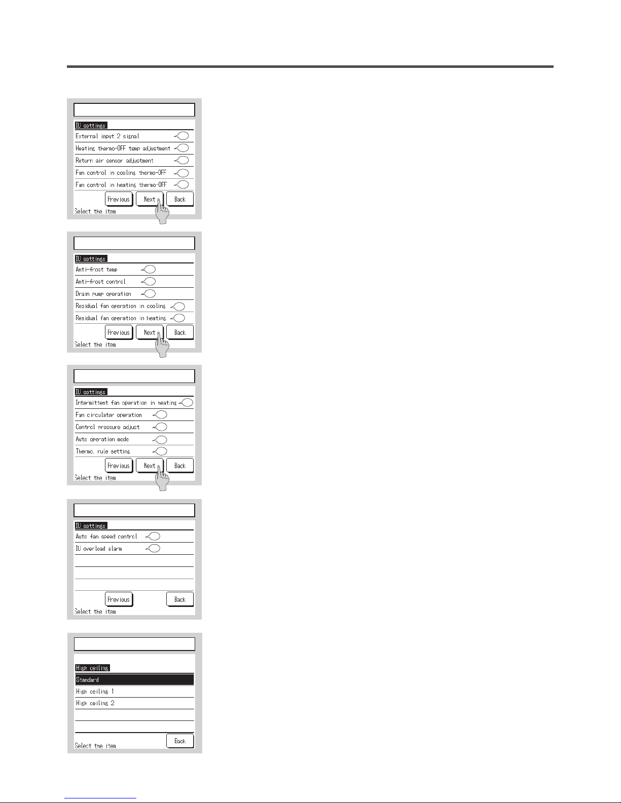
8. IU settings
IU settings cover the following items. These settings can be done only when the unit is stopped.
(1) High ceiling: Set the fan speed for High ceiling operation. ➝
⑪
(2) Filter sign: Set the time to display the filter sign. ➝
⑫
(3) External input 1: Set the control at the time when the signal is input to the external input 1 (CNT) of IU. ➝
⑬
(4) External input 1 signal: Set the type of signal to input to the external input 1 (CNT) of IU. ➝
⑭
(5) External input 2: Set the control at the time when the signal is input to the external input 2 (CNTA) of the IU
equipped with the external input 2. ➝
⑮
(6) External input 2 signal: Set the type of signal to input to the external input 2 (CNTA) of the IU. ➝
⑯
(7) Heating thermo-OFF temp adjustment: Adjust the temperature for judging to make thermostat ON or OFF
during heating operation. ➝
⑰
(8) Return air sensor adjustment: Adjust the temperature detected with the return air temp sensor. ➝
⑱
(9) Fan control in cooling thermo-OFF: Set the fan control during cooling thermo-OFF. ➝
⑲
(10) Fan control in heating thermo-OFF: Set the fan control during heating thermo-OFF. ➝
⑳
(11) Anti-frost temp: Select the Anti-frost control temperature. ➝
(12) Anti-frost control: Set the fan control during the Anti-frost control. ➝
(13) Drain pump operation: Set the operation mode to operate the drain pump. ➝
(14) Residual fan operation in cooling: Select the residual fan operation time after stopping and thermo-OFF in
cooling operation. ➝
(15) Residual fan operation in heating: Select the residual fan operation time period after stopping and thermo-OFF
in heating operation.➝
(16) Intermittent fan operation in heating: Select the fan control after the residual fan operation following stopping
and thermo-OFF in heating operation.➝
(17) Fan circulator operation: Set this when operating the fan as a circulator. ➝
(18) Control pressure adjust: Adjust the control pressure when connecting the outdoor air conditioning unit to the
Multi (KX) System. ➝
(19) Auto operation mode: Set the control method for the auto operation mode. ➝
(20) Thermo rule setting: Set the switching methods and conditions for the thermo rule. ➝
(21) Auto fan speed control; Set the switching range of the fan tap at the auto fan speed setting. ➝
(22) IU overload alarm: Overload alarm signal is transmitted when the room temperature differs to some extent
from the setting temperature at 30 minutes after the start of operation. ➝
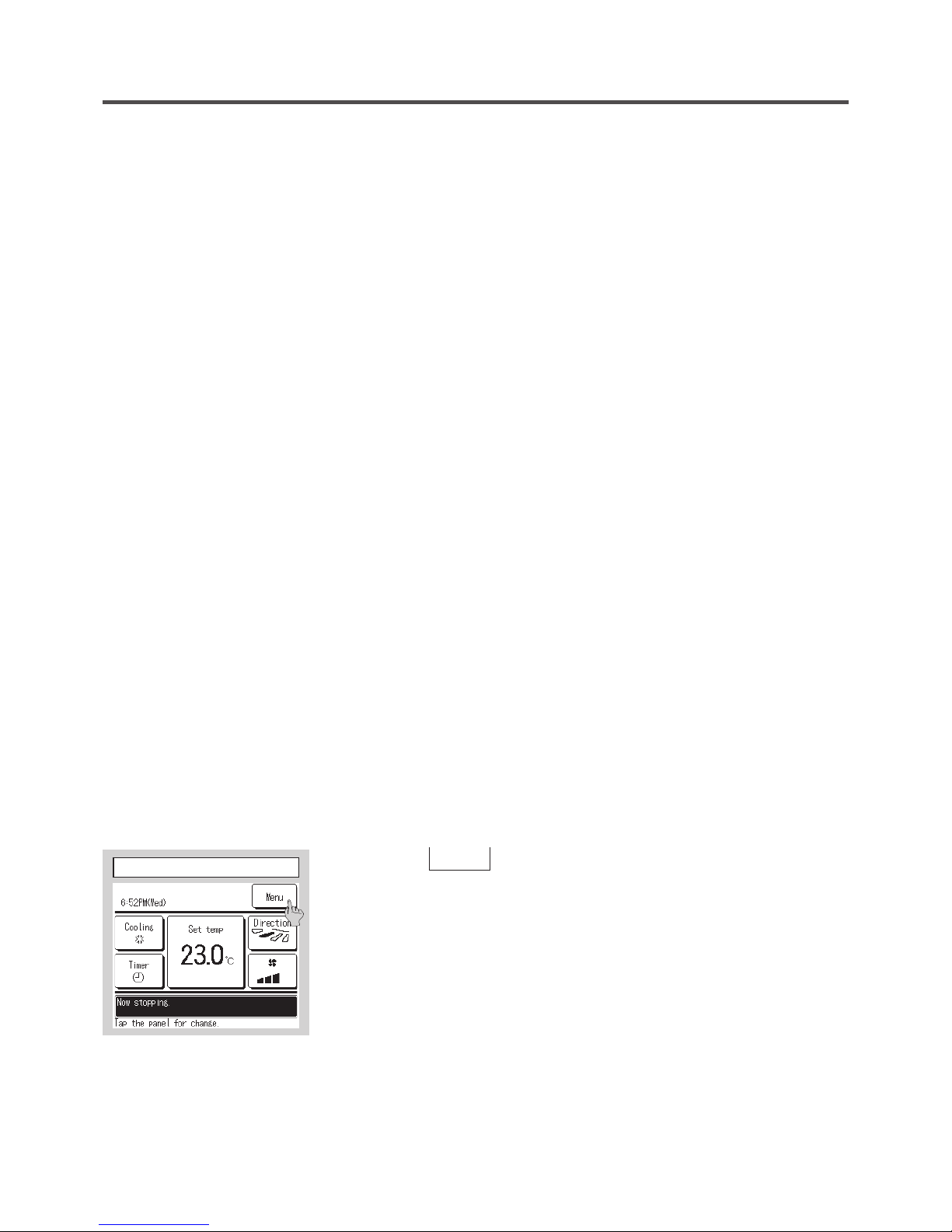
①
Tap the
Menu
button on the TOP screen.
①
TOP screen
— 27 —
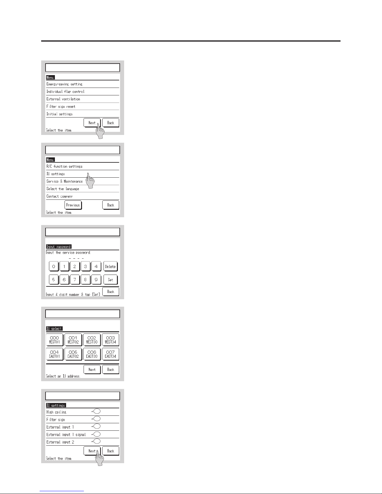
②③
Main menu screen is displayed.
Tap the “IU settings” on the menu screen.
④
Display the service password input screen.
Enter the service password (4-digit number).
The service password is “9999”. (Unable to change)
⑤
When plural indoor units are connected, select the IU for the
IU settings.
When the name/address of IU connected are displayed, select the unit to be
set.
If all units are selected, the same setting is done for all units.
②
Menu screen 1
③
Menu screen 3
④
Service password input
⑤
Select IU
⑥~⑩
IU settings menu screens are displayed after receiving
data from the IU.
⑥
IU setting menu 1
11
12
13
15
14
— 28 —
— 29 —
⑦
IU setting menu 2
⑧
IU setting menu 3
⑨
IU setting menu 4
16
17
18
20
19
21
22
23
25
24
26
27
28
40
29
⑪
High ceiling
Set the fan speed tap for the IU.
It may not be available to set depending on IU models connected.
⑩
IU setting menu 5
⑪
High ceiling
44
45
— 29 —
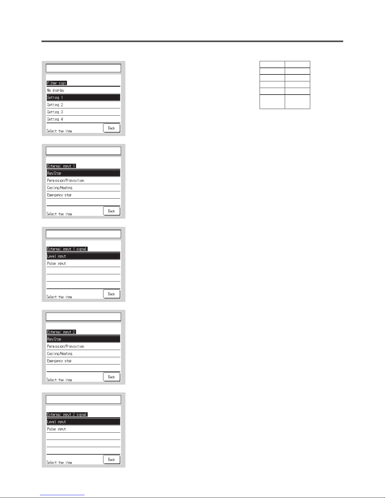
⑫
Filter sign
Set the time to display the filter sign.
⑬
External input 1
Set the control at the time when the signal is input to the external input 1
(CNT) of IU.
⑫
Filter sign
⑬
External input 1
Standard
No display None
Setting 1 180Hr
Setting 2 600Hr
Setting 3 1,000Hr
Setting 4
1,000Hr
Operation stop
⑭
External input 1 signal
Set the signal type to input to the external input 1 (CNT) of IU.
⑮
External input 2
⑯
External input 2 signal
This is operable when the IU equipped with the external input 2 is connected.
⑭
External input 1 signal
⑮
External input 2
⑯
External input 2 signal
 Loading...