

Mitsubishi Heavy Industries BD2g, BS3g User Manual
MANUAL
C/
#:
28000001-UP
28500001-UP
38000001-UP
281 00001-UP
28600001-UP
381 00001-UP
(v
28200001-UP
28700001-UP
38500001-UP
28300001-UP
38600001-UP
MITSUBISHI
TRACTOR
BD2G
TRACTOR
SHOVEL
BS3G
+
MITSUBISHI
I"-
HEAVY
INDUSTRIES,
LTD.

Chassis
and
Engine Serial
Number
Locations
Chassis and engine serial numbers are stamped in locations
and forms shown.
When ordering replacement parts or asking your local
Mitsubishi dealer
to
repair
your
machine, be sure
to
give
these serial numbers and service meter reading .
• BD2G
Engine serial number
(right side
of
machine)
~
MODEL I 1
MACHINE
No.c:::::::J
ENG
INE
No.c:::::::J
MIT.UBISHI
HEAVY
INDuSTRIES,
LTD.
rCK"t1I
JAf'AH
Nameplate
(left side
of
machine)
___
.!::==::!:=:==---L
'.
Chassis serial 'number
(left-side
of
machine)
502615
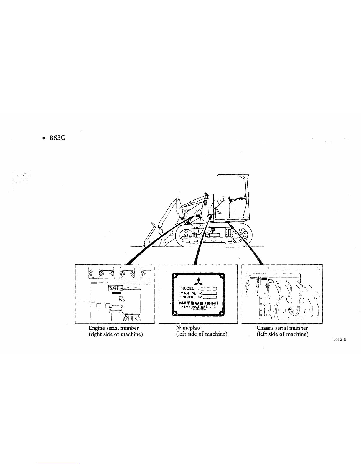
• BS3G
o
Engine serial number
(right side
of
machine)
J...
MODEL I I
MACHINE
No.c::::::J
ENG
IN
E No.c::::=:::J
MIT.UBIBWI
HEAVY INDUSTRIES, LTD.
TOKYO
JAn.No
Nameplate
(left side
of
machine)
Chassis serial number
(left side
of
machine)
502616
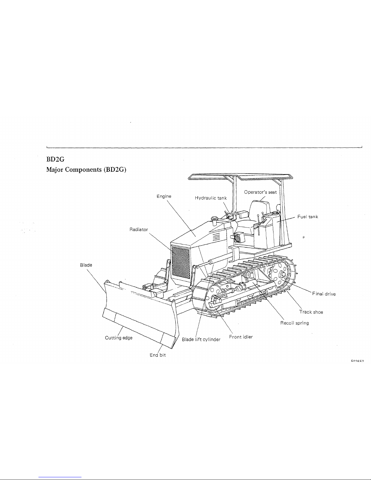
BD2G
Major
Components (BD2G)
Radiator
Blade
Cutting
edge
Engine
Front
idler
bit
Fuel
tank
Final drive
Track
shoe
Recoil spring
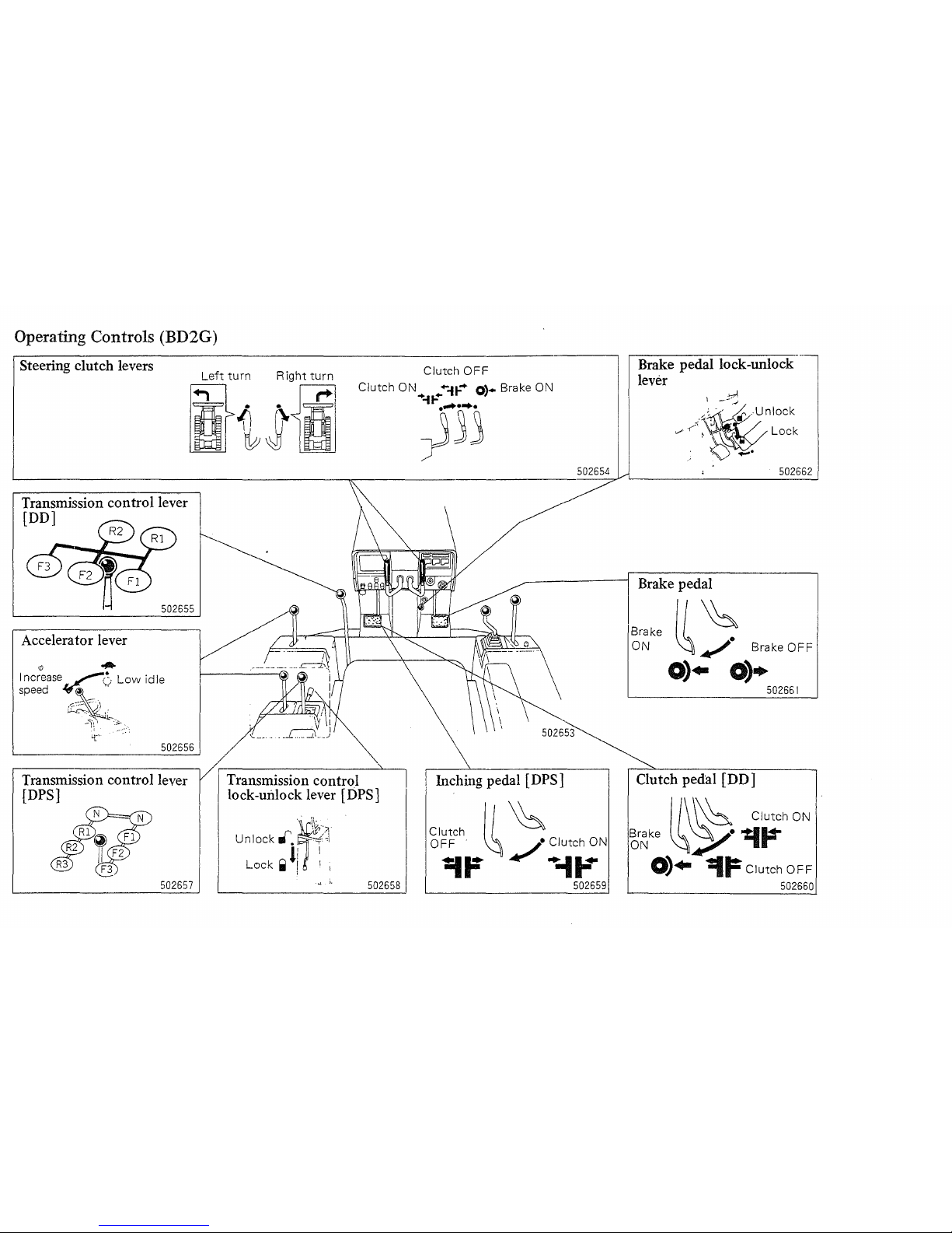
Operating Controls (BD2G)
Steering
clutch
levers
Left
turn
Right
turn
Clutch
OFF
it~\i
Clutch ON
....
n-
....
0'.
Brake ON
......
~..
'I
Transmission
control lever
[DO]
502655
Accelerator
lever
502656
Transmission
control lever
{DPS]
502657
Transmission
control
lock-unlock
lever
[DPS]
..
\\.
Unlock
rtf.~~~}
li
1
Lock
..
! ! I
;
"
..
502658
)33
502654
Inching
pedal
[DPS]
Clutch II
~
OFF
.
~
j.
Clutch ON
~F
.,
+-11-"
502659
Brake
pedal lock-unlock
lever
502662
Brake
pedal
Brake
~~
ON
~.
At'
Brake
OFF
0)"
0)+
502661
Clutch
pedal [DO]
1/\
\h
Clutch ON
~~ke
~~.~~
0)"
-=I~
Clutch
OFF
502660
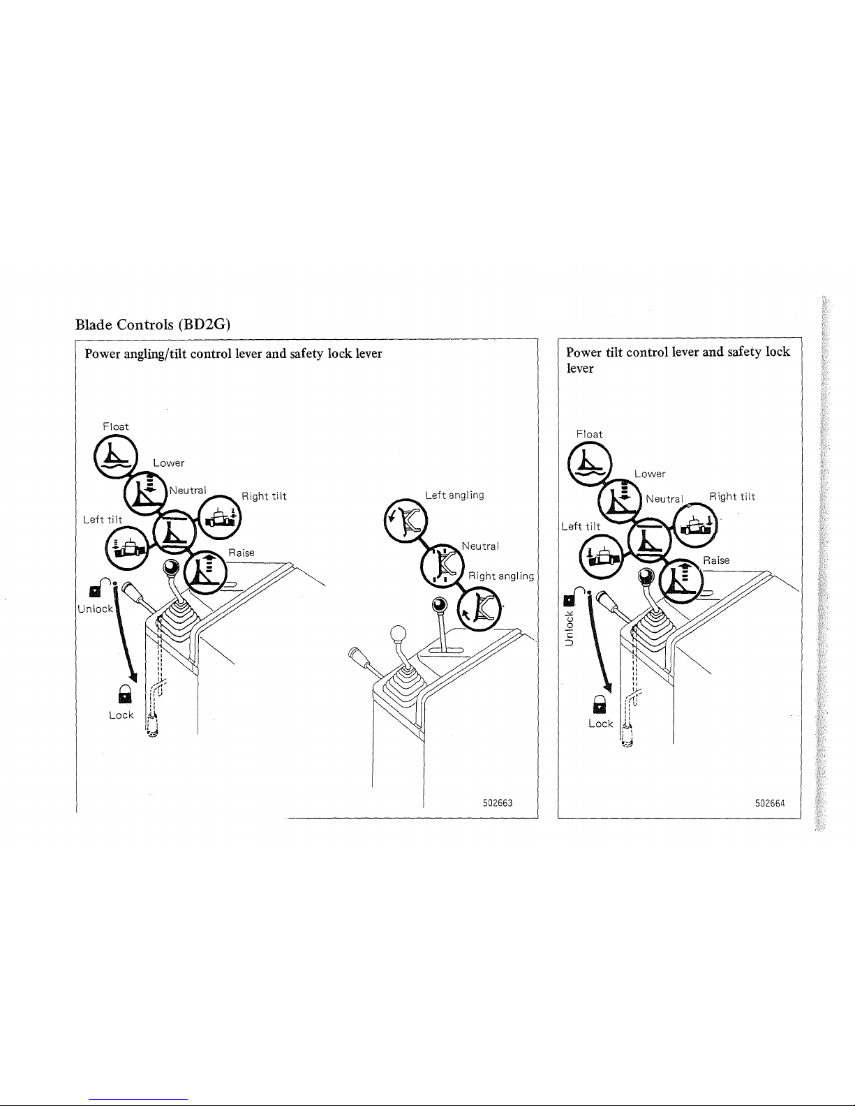
Blade Controls (BD2G)
Power angling/tilt control lever and safety lock lever
Float
502663
Power tilt control lever and safety lock
lever
Float
502664
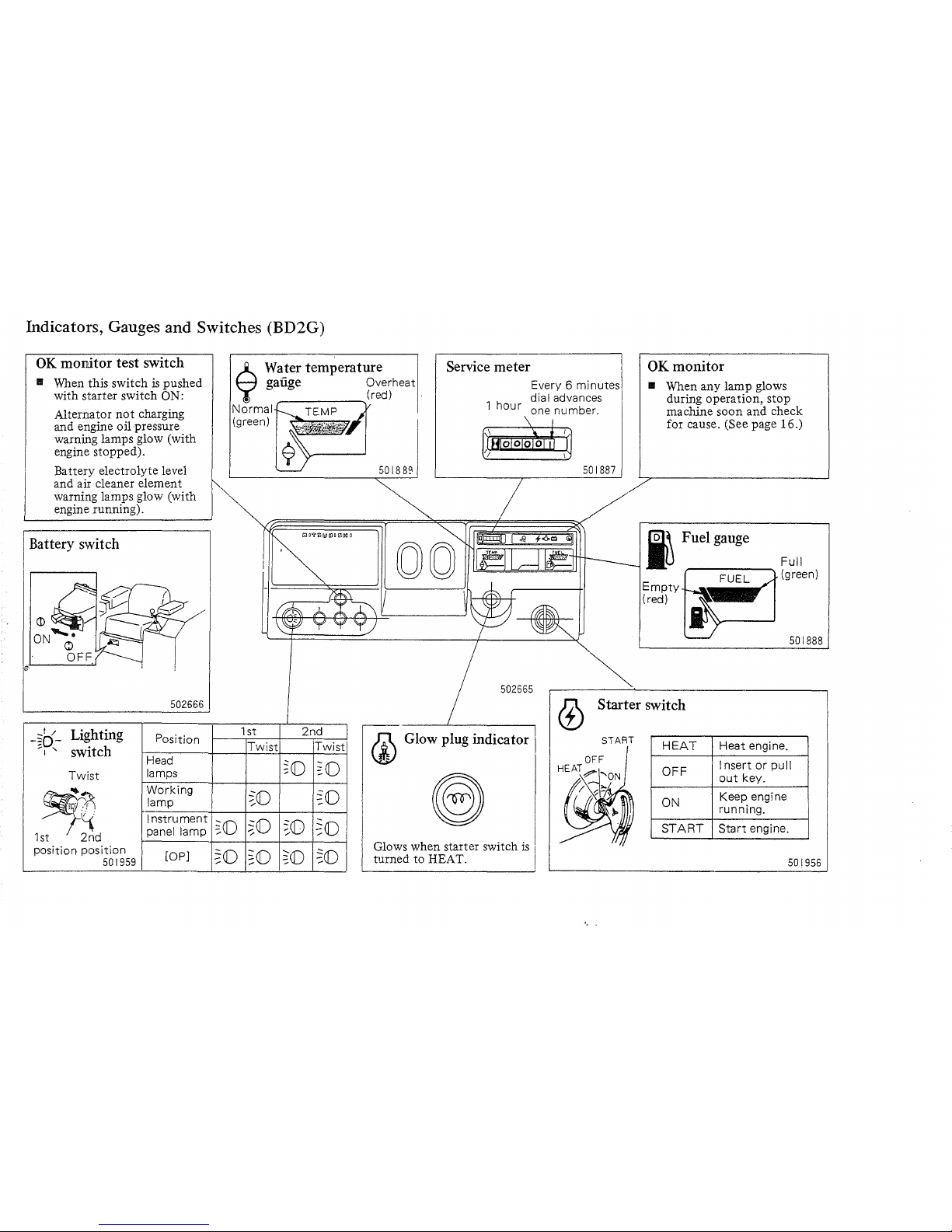
Indicators, Gauges and Switches (BD2G)
OK
monitor test switch
.. When this switch
is
pushed
with starter switch
ON:
Alternator
not
charging
and engine oil pressure
warning lamps glow (with
engine stopped).
Ba
ttery
electrolyte level
and air cleaner element
warning lamps glow (with
engine running).
Battery switch
@i·.L-.---"------<.J
-§o-
Lighting
~I"
switch
Twist
~
1st 2nd
position
position
501959
502666
Position
Head
lamps
Working
lamp
Instrument
panel lamp
rop)
$
Water
temperature
gauge Overheat
.--
______
(red) .
Normal
TEMP
(green)
50
1889
Service meter
Every 6 minutes
dial advances
1
hour
one number.
501887
00
502665
OK
monitor
..
When any lamp glows
during operation, stop
machine soon and check
for cause. (See page 16.)
I Fuel gauge
Empty
(red)
Full
(green)
501888
1st
2nd
(l)
Starter switch
Twist
'Twist
Glow plug indicator
Glows when starter switch
is
I
turned to HEAT.
".
START
HEAT
OFF
ON
START
Heat engine.
I nsert
or
pull
out
key.
Keep engine
running.
Start
engine.
501956
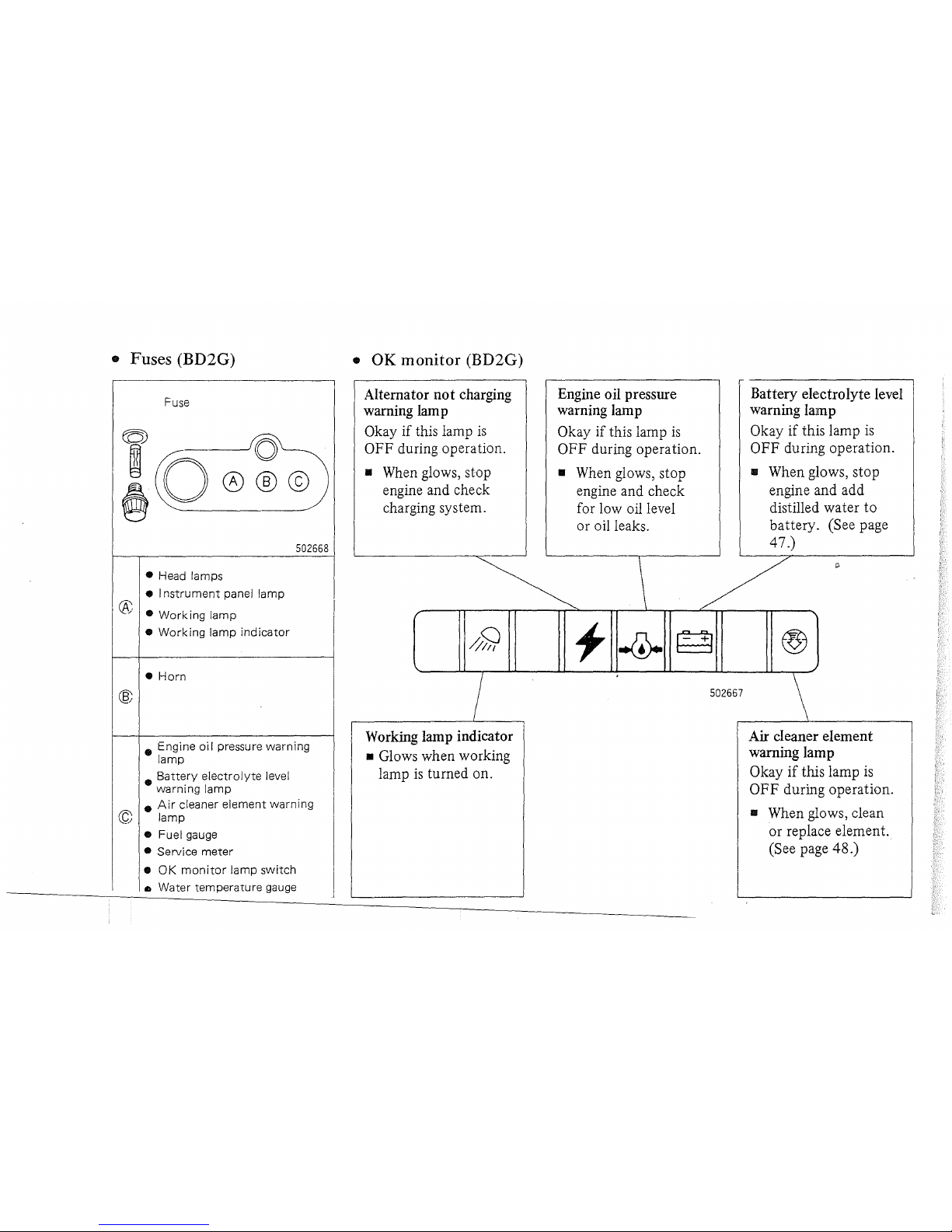
• Fuses (BD2G)
®
Fuse
502668
• Head lamps
• I
nstrument
panel lamp
•
Working
lamp
•
Working
lamp
indicator
•
Horn
• Engine
oil
pressure warning
lamp
•
Battery
electrolyte
level
warning lamp
•
Air
cleaner element warning
© lamp
• Fuel gauge
• Service
meter
•
OK
monitor
lamp
switch
III
Water
temperature
gauge
•
OK
monitor
(BD2G)
Alternator
not
charging
warning lam p
Okay if this lamp
is
OFF during operation.
• When glows, stop
engine and check
charging system.
7
,--------------L-----
1
Working lamp indicator
• Glows when working
lamp
is
turned on.
Engine oil pressure
warning lamp
Okay if this lamp
is
OFF during operation.
• When glows, stop
engine and check
for low oil level
or oil leaks.
Battery electrolyte level
warning lamp
Okay
if
this lamp
is
OFF during operation.
• When glows, stop
engine and add
distilled water
to
battery. (See page
47.)
\ /
502667
\
Air cleaner element
warning lamp
Okay
if
this lamp
is
OFF
during operation.
• When glows, clean
or replace element.
(See page 48.)

Others (BD2G)
Horn
switch
Operator's seat
(fore-aft adjustment)
502669
502670
Operator's seat (turning over)
.-
1:1
---.::::.?\
lL~
\ \
iJF
1---
~
l~//--
'------,--'
I
Seat support
A
WARNING
. Be sure to. support seat after turn-
ing it over.
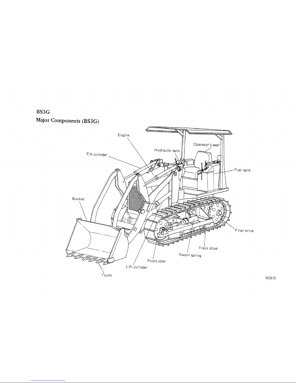
BS3G
Major Components (BS3G)
Engine
Tilt cylinder
Fuel
tank
Bucket
Final
drive
Track
shoe
Tooth
502672
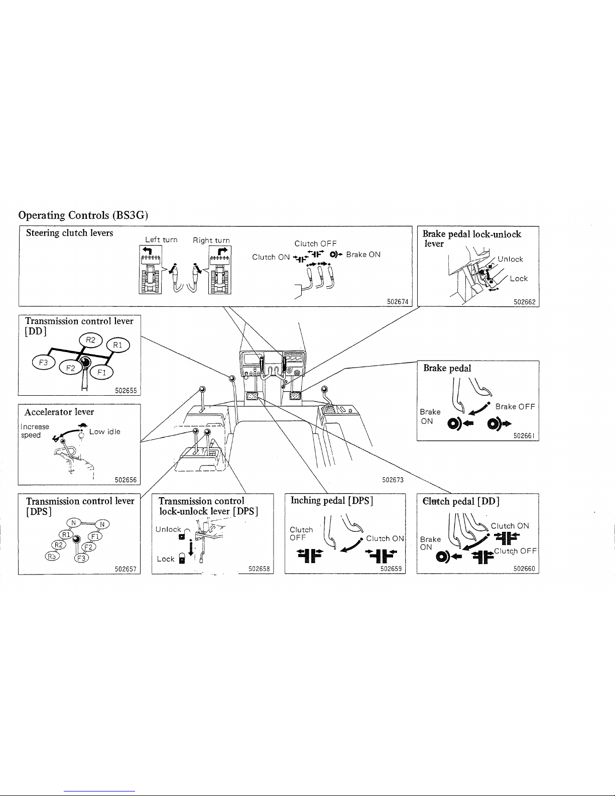
Operating Controls (BS3G)
Steering
clutch
levers
Transmission
control lever
(DD]
502655
Accelerator
lever
502656
Transmission
control lever
(DPS]
502657
Clutch
OFF
Clutch ON
.....
t-
.....
it-
..
0)·
Brake ON
~'Ij
Transmission
control
lock-unlock
lever
[DPS]
\-.
r\'
:;:~--.
-'
unIOc~.~
Lock
..
l;
j
502658
502674
Inching
pedal
[DPS]
Clutch
·11
'~
O~F
~/~-I;~N
502659
Brake
pedal lock-unlock
lever
Lock
502662
Brake
pedal
II
~
8rnk'
OFF
Brake
~..,
ON
0).
o~
502661
Elmch
pedal
[D D ]
~
\
~
Clutch
ON
Brake .
~'0$.../.
'=I~
ON
~~
0).
lIt=Clutc,h
OFF
502660
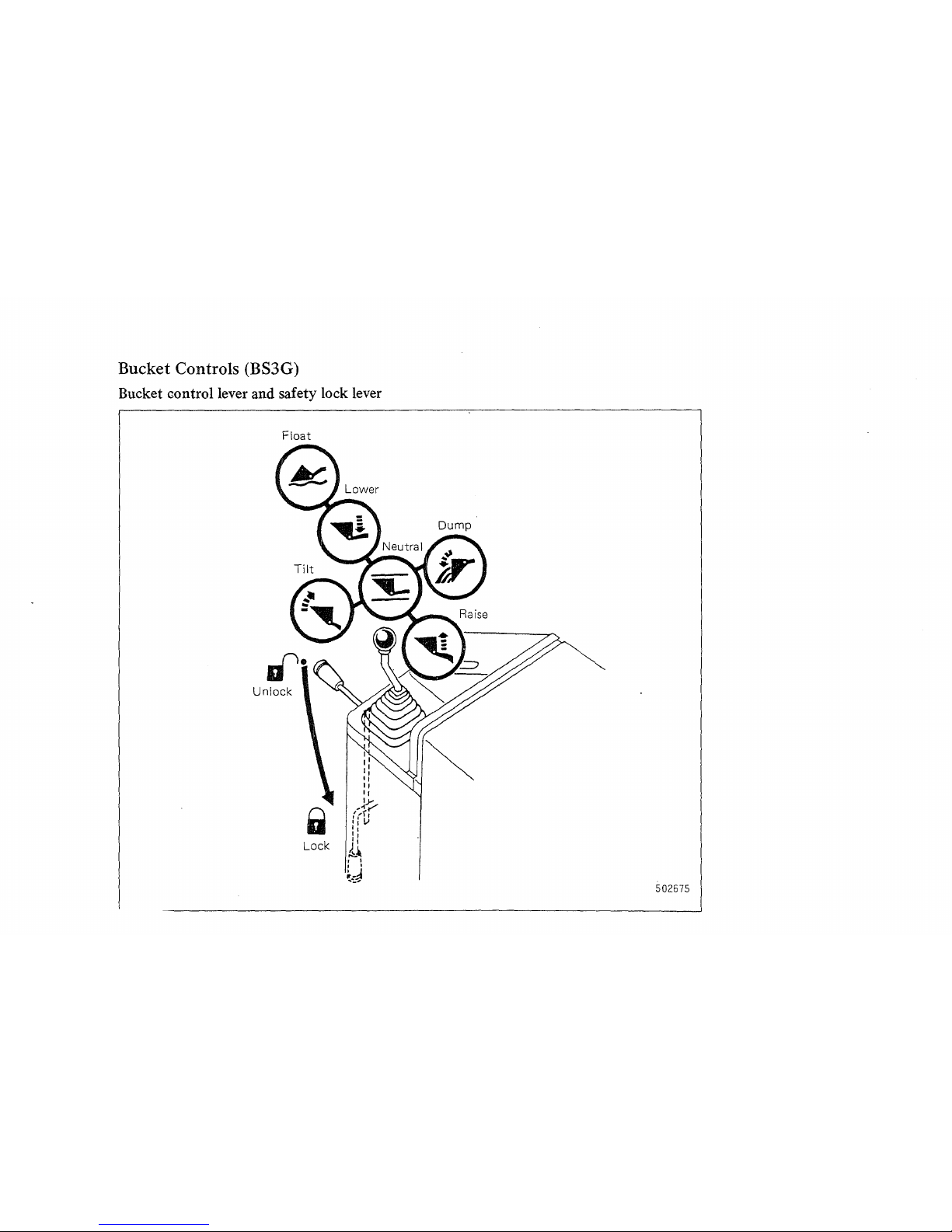
Bucket Controls (BS3G)
Bucket control lever and safety lock lever
Float
502675
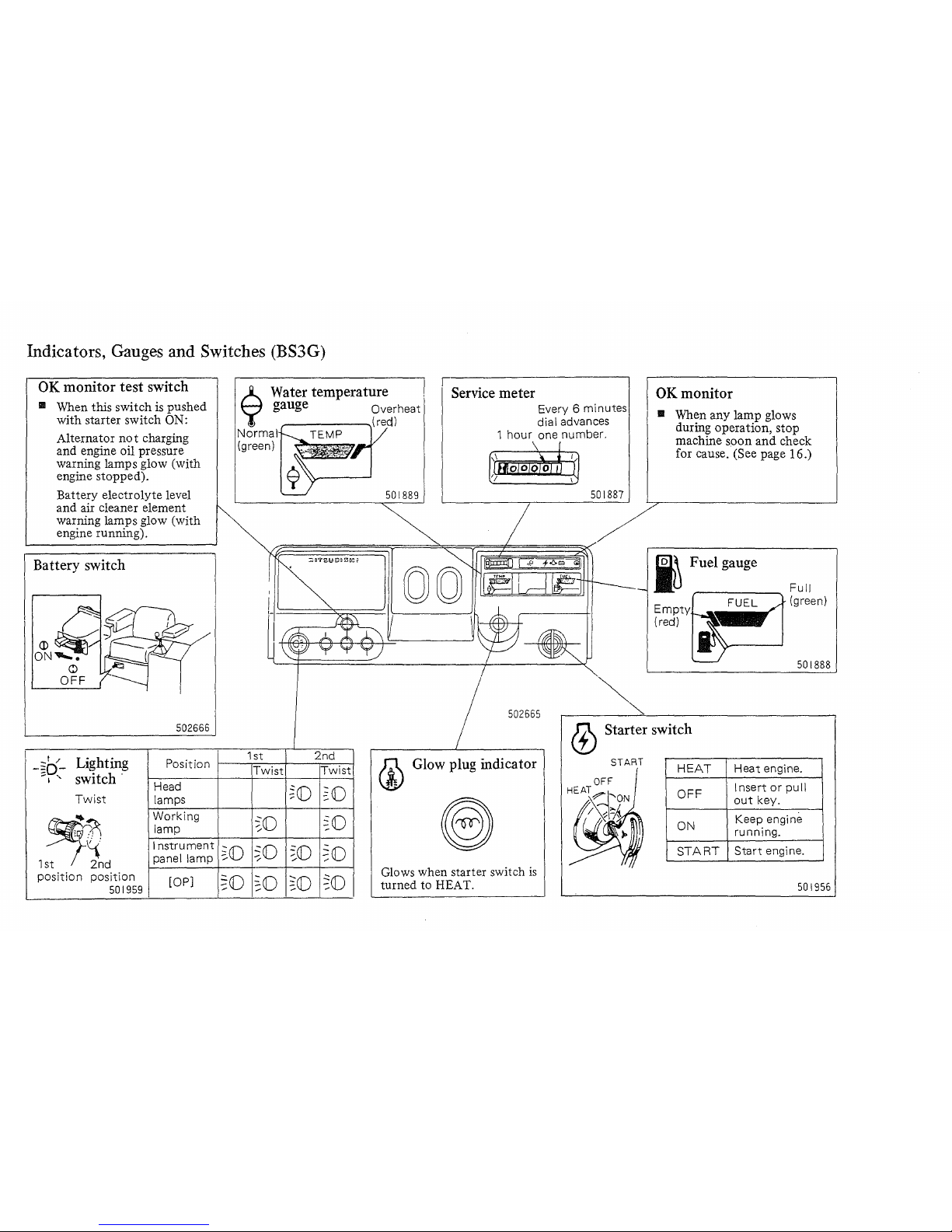
Indicators, Gauges and Switches (BS3G)
OK monitor
test
switch
III When this switch
is
pushed
with starter switch
ON:
Alternator
not
charging
and engine oil pressure
warning lamps glow (with
engine stopped).
Battery electrolyte level
and air cleaner element
warning lamps glow (with
engine running).
Battery switch
502666
_I
/
Lighting
-~D-
Position
-I
"
switch -
Head
Twist
lamps
~
Working
lamp
Instrument
1st
2nd
panel lamp
position
position
lOP]
501959
6 Water temperature ,
);
gauge Overheat
Norma
TEMP
(green)
501889
Service meter
Every 6 minutes
dial advances
1
hour
one number.
501881
502665
OK
monitor
III When any lamp glows
during operation, stop
machine soon
and
check
for cause. (See page 16.)
i Fuel gauge
Empty
(red)
Full
(green)
501888
1 st
2nd
(j)
Starter switch
Twist
Twist
~(j)
~O
~(j)
~O
~(j)
~(j)
,-
~(j)
~O
~(j)
~O
~(j)
~(j)
Glow plug indicator
Glows when starter switch
is
turned to HEAT.
START
HEAT
OFF
ON
START
Heat
engine.
Insert
or
pull
out
key.
Keep engine
running.
Start
engine.
501956
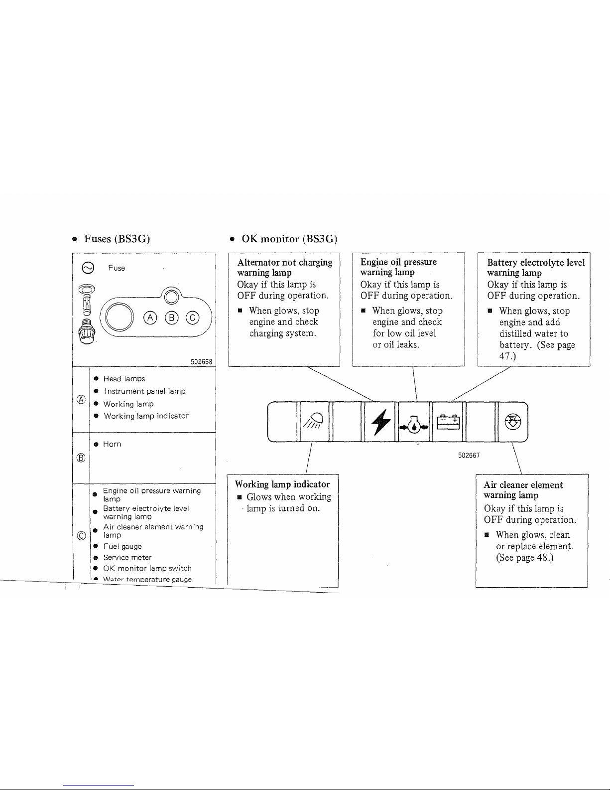
• Fuses (BS3
G)
e Fuse
(Ql~
&0
@@©)
• Head lamps
• I
nstrument
panel
lamp
® •
Working
lamp
•
Working
lamp
indicator
•
Horn
502668
• Engine
oil
pressure warning
lamp
•
Battery
electrolyte
level
warning
lamp
•
Air
cleaner element warning
© lamp
• Fuel gauge
• Service
meter
i.
OK
monitor
lamp
switch
\.
IAbtpr
tAmoerature gauge
•
OK
monitor (BS3G)
Alternator not
charging
warning
lamp
Okay
if
this lamp
is
OFF during operation.
.. When glows, stop
engine and check
charging system.
I
Working
lamp
indicator
II
Glows when working
. lamp
is
turned on.
-
Engine oil
pressure
warning
lamp
Okay
if
this lamp
is
OFF during operation.
.. When glows, stop
engine and check
for low oil level
or oil leaks.
Battery electrolyte level
warning
lamp
Okay if this lamp
is
OFF during operation.
II
When glows, stop
engine and add
distilled water
to
battery. (See page
47.)
\ /
f
502667
\
Air
cleaner element
warning
lamp
Okay
if
this lamp
is
OFF during operation.
II
When glows, clean
or
replace element.
(See page 48.)
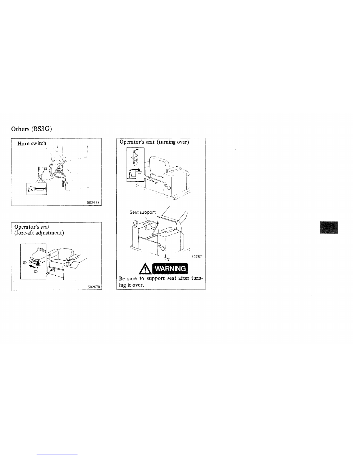
Others (BS3G)
Horn switch
I I
".,1
:
Operator's seat
(fore-aft adjustment)
Operator's seat (turning over)
502669
WARNING
Be
sure to support
seat
after turn-
502670
ing
it
over.
L-
____________________
~~
L-
______________________
__
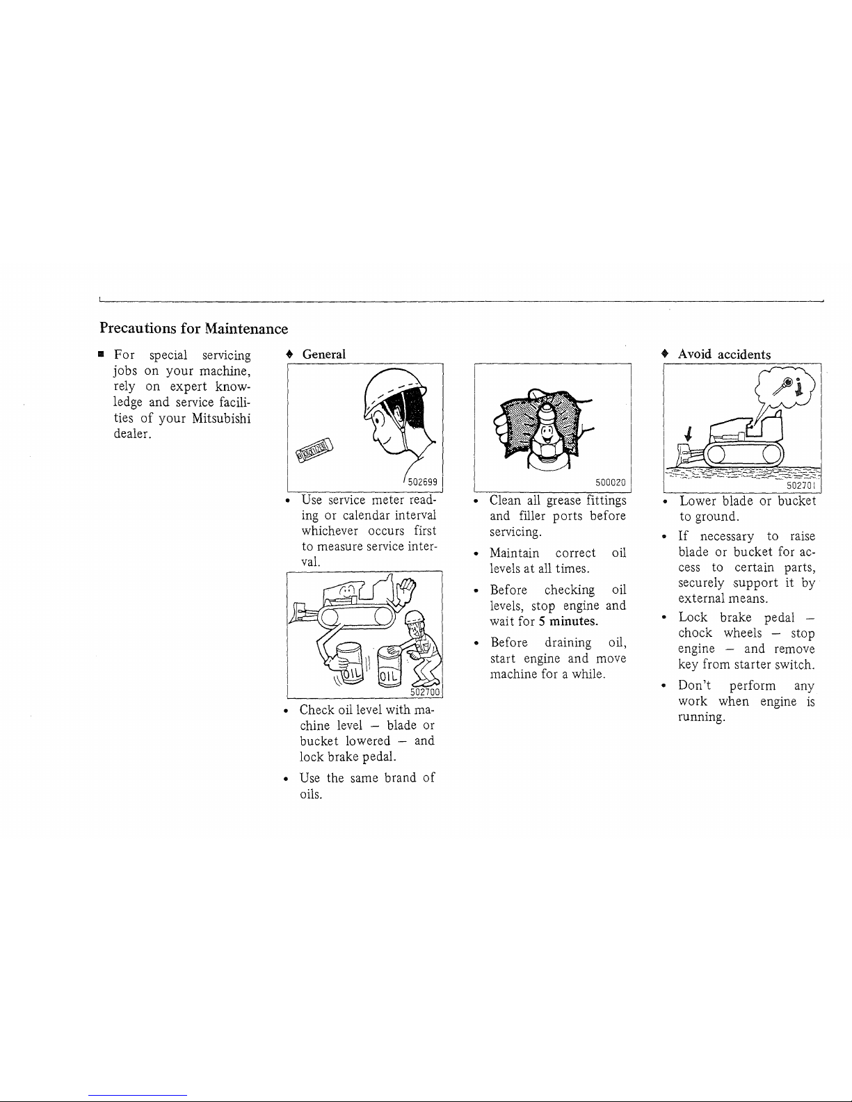
Precautions for Maintenance
..
For
special servlcmg
jobs
on
your
machine,
rely
on
expert
knowledge and service facilities
of
your
Mitsubishi
dealer.
• General
502699
I
• Use service meter reading or calendar interval
whichever occurs first
to measure service interval.
• Check oil level with
machine level - blade or
bucket lowered - and
lock brake pedal.
• Use the same brand
of
oils.
500020
• Clean all grease fittings
and filler ports before
servicing.
• Maintain correct oil
levels
at
all times.
• Before checking oil
levels, stop engine and
wai t for
5 minutes.
• Before draining oil,
start engine and move
machine for a while.
• Avoid accidents
50270
I
• Lower blade
or
bucket
to ground.
•
If
necessary to raise
blade
or
bucket
for access to certain parts,
securely
support
it
by
external means.
• Lock brake pedal chock wheels - stop
engine - and remove
key from starter switch.
•
Don't
perform any
work
when
engine
is
running.

502702
•
Attach
"DO NOT
OP-
ERA
TE"
tag when
servicing, adjusting or
repairing machine.
• Keep
off
personnel
while at
work
on
ma-
chine.
502703
• Start and operate engine only in well ventilated area.
•
Don't
smoke while
servicing fuel system - or
refueling.
o Store oily rags and
other combustible materials in a safe place.
500022
• Before removing radiator
cap or hydraulic
tank cap after operation, wait until machine
cools down
to
avoid
having scalding
hot
coolant or oil blown
out.
Before removing filler
cap, loosen
it
slowly to
relieve pressure.
500024
• Disconnect
battery
cables before servicing
electrical system.
• Battery electrolyte
is
very corrosive.
If
you
drip
it
on
your
skin
or
clothing, flush
it
off
at
once with water.
•
Don't
touch
exhaust
pipe immediately after
shutting down engine.
Preparation for Use
• For
your
own safety and maximum
service life
of
machine, make a
walk-around inspection before
mounting machine or starting
engine. Check under and around for
the following items:
Bolts and nuts
Check for loose or missing bolts,
especially
on
blade, air cleaner and
track parts.
Oil compartments
Check oil levels in oil pan and other
compartments. Also check for leaks.
Fuel system
Check oil level in fuel tank. Check
system for leaks.
Cooling system
Check coolant level in radiator.
Check for leaks.
Electrical system
Check electrolyte level in battery.
Check for loose terminals. Make
sure gauges and lamps operate
properly.
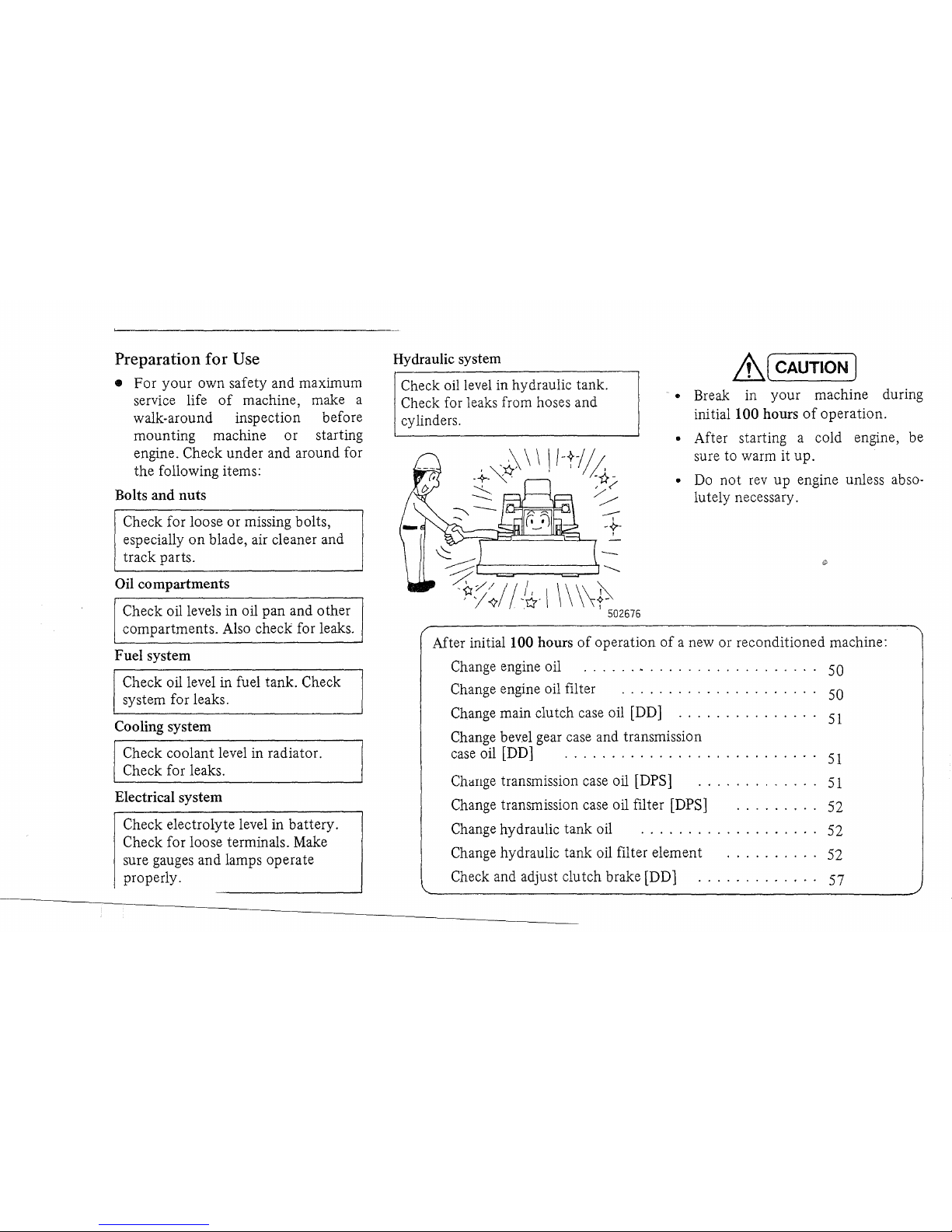
Hydraulic system
Check oil level in hydraulic tank .
Check for leaks from hoses and
cylinders.
---
-~.
>==;~~~:::L.,
I
\\
\\~
I 502676
~(
CAUTION)
• Break in your machine during
initiallOO hours
of
operation.
• After starting a cold engine, be
sure to warm it up.
•
Do
not
rev
up
engine unless abso-
lutely necessary.
After
initialI00
hours
of
operation
of
a new or reconditioned machine:
Change engine oil
......
. . . . . . . . . . . . . . . . .
..
50
Change engine oil filter . . . . . . . . . . . . . . . . . . . 50
Change main clutch case oil [DD]
...............
51
Change bevel gear case and transmission
case
oil [DD] . . . . . . . . . . . . . . . . . . . . . . . . .
..
51
ChaIlge transmission case oil [DPS]
..........
.
..
51
Change transmission case oil filter [DPS]
.......
" 52
Change hydraulic tank oil . . . . . . . . . . . . . . . . .
..
52
Change hydraulic tank oil filter element
..........
52
Check and adjust clutch brake [DD]
.............
57
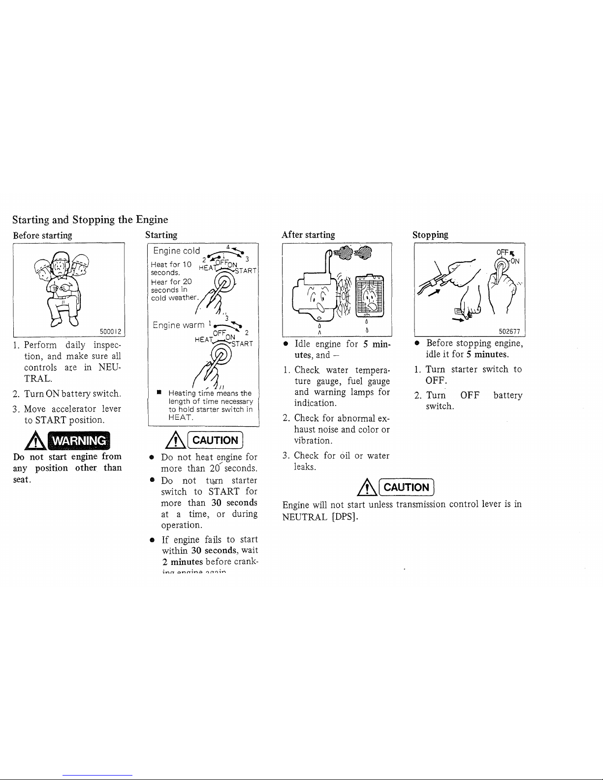
Starting and Stopping the Engine
Before starting
500012
1.
Perform daily inspec-
tion, and make sure all
controls
a:ce
in NEU-
TRAL.
2.
Turn ON battery switch.
3. Move accelerator lever
to START position.
A
WARNING·
Do
not
start engine from
any position other
than
seat.
Starting
Engine cold
~
2"-~1
... 3
Heat
for
10
HEAfFFON
seconds.
;t~START
Hear
for
20
seconds
in
cold
weather.
'3
Engine
warm
1
~
OFF
ON
2
l:START
..
Heating
time
means
the
length
of
time
necessary
to
hold
starter
switch
in
HEAT.
&,,(
CAUTION)
• Do
not
heat engine for
more than
20/ seconds.
•
Do
not
tl¥n
starter
switch to START for
more than
30 seconds
at a time, or during
operation.
•
If
engine fails to start
within
30 seconds, wait
2 minutes before crank-
After starting
• Idle engine for 5 minutes,
and-
1.
Check water temperature gauge, fuel gauge
and warning lamps for
indication.
2.
Check for abnormal
ex-
haust noise and color or
vibration.
3. Check for
oil
or water
leaks.
Stopping
502677
• Before stopping engine,
idle
it
for 5 minutes.
1.
Turn starter switch to
OFF.
2.
Turn
OFF
battery
switch.
&,,(
CAUTION)
Engine will not start unless transmission control lever
is
in
NEUTRAL
[DPS].
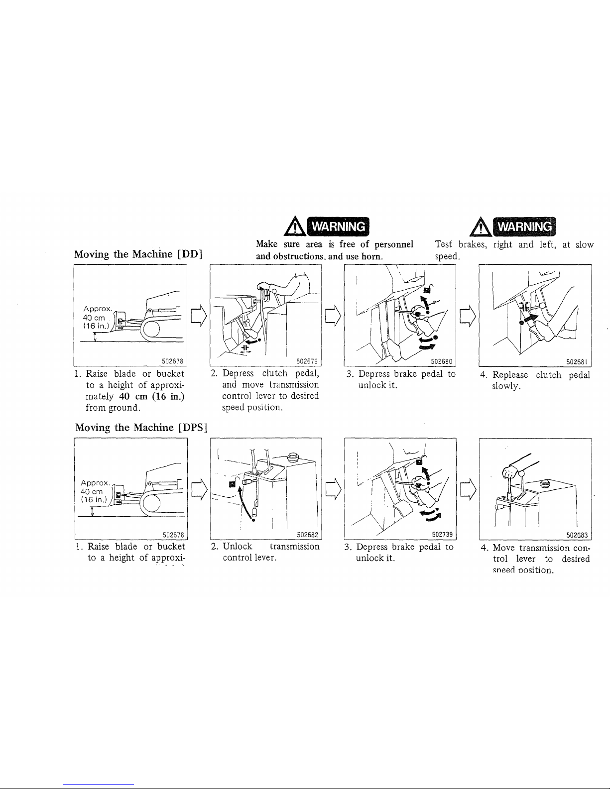
Moving the Machine [D D ]
502678
1.
Raise blade
or
bucket
to
a height
of
approxi-
mately
40
em
(16
in.)
from ground.
Moving the Machine [DPS]
502678
1.
Raise blade
or
bucket
to
a height
of
approxi-
WARNING
.&
Make
sure
area
is
free
of
personnel
and obstructions. and use horn.
Test brakes, right
and
left,
at
slow
speed.
502679
2.
Depress clutch pedal,
and move transmission
control lever to desired
speed position.
502682
2. Unlock transmission
control lever.
3.
Depress brake pedal to
unlock it.
j . I
/--\.
i
./
./
,.
/'
)V
502739
3. Depress brake pedal
to
unlock
it.
502681
4. Replease
clutch
pedal
slowly.
If!
502683
4.
Move transmission control lever
to
desired
."need Dosition.
 Loading...