

Mitsubishi Heavy Industries 25ZMX-S, 35ZMX-S, 60ZMX-S, SRK20ZMX-S, 50ZMX-S Technical Manual

TECHNICAL MANUAL
INVERTER WALL MOUNTED TYPE
RESIDENTIAL AIR-CONDITIONERS
(Split system, air to air heat pump type)
SRK20ZMX-S
25ZMX-S
35ZMX-S
50ZMX-S
60ZMX-S
Manual No.'13sSRK-T-144D
DRAFT

-
1
-
'13 • SRK-T-144D
gs32+4
CONTENTS
1. SPECIFICATIONS ........................................................................................ 2
(2) Outdoor units ....................................................................................... 8
..................................................... 20
2EMOTECONTROL
..................................................................................... 10
......................................................................... 7
(1) Indoor units .......................................................................................... 7
2. EXTERIOR DIMENSIONS
3. ELECTRICAL WIRING .............................................................................. 11
(1) Indoor units .......................................................................................... 11
4. NOISE LEVEL ............................................................................................ 14
(2) Outdoor units ....................................................................................... 12
6. RANGE OF USAGE & LIMITATIONS
................................................................................... 22
7. CAPACITY TABLES
5. PIPING SYSTEM ...................................................................................... 19
.................................................................................. 24
8. APPLICATION DATA
9. OPTION PARTS .......................................................................................... 44
7IREDREMOTECONTROL2#%
3UPERLINK%BOARD3#!$.!%
)NTERFACEKIT3#")+.%
..................................................................... 56
10. TECHNICAL INFORMATION
)NSTALLATIONOFINDOORUNIT
)NSTALLATIONOFOUTDOORUNIT .................................................................. 28
■How to read the model name
Example: SRK 20 ZMX
Series code
Inverter type
Product capacity (Cooling capacity : 2.0kW)
Model name SRK : Wall mounted type
SRC : Outdoor unit
S
-
-
2
-
'13 • SRK-T-144D
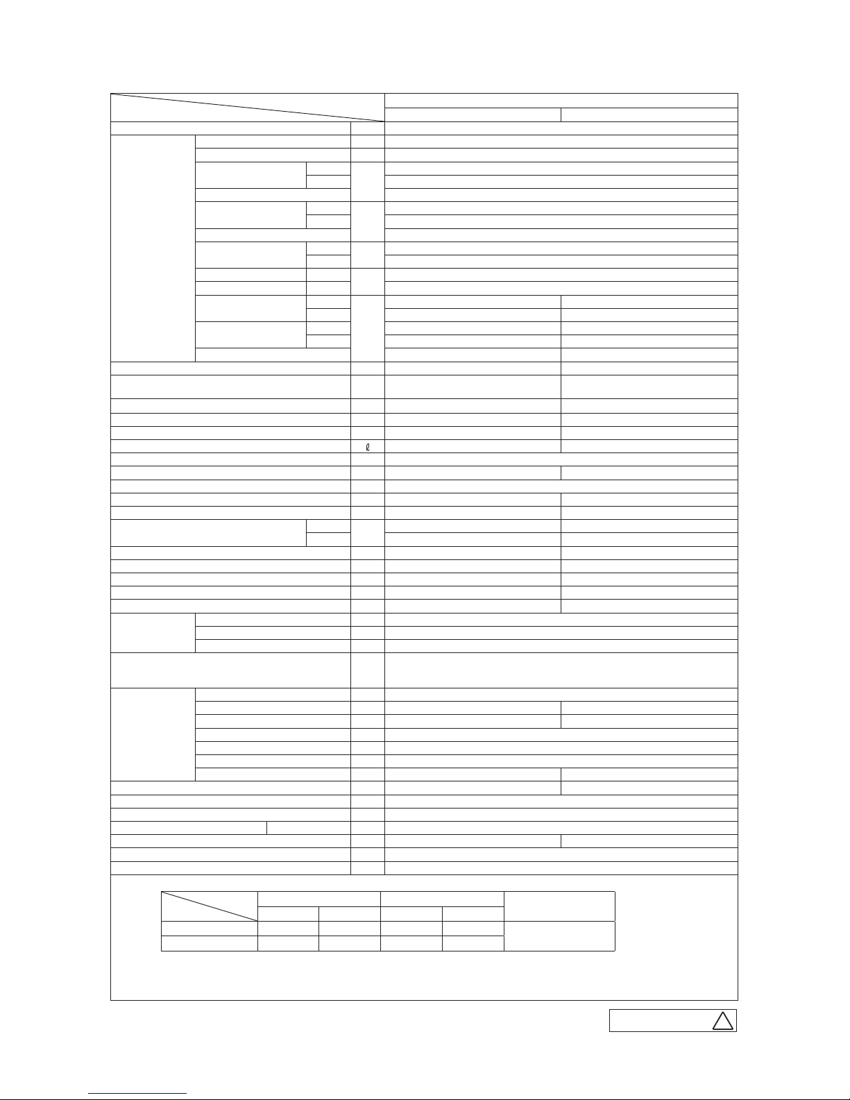
1. SPECIFICATIONS
Model
Item
SRK20ZMX-S
Indoor unit SRK20ZMX-S Outdoor unit SRC20ZMX-S
Power source Single phase, 220 - 240V, 50Hz
Operation
data
Nominal cooling capacity (range) kW 2.0 ( 0.9 (Min.) - 3.1 (Max.))
Nominal heating capacity (range) kW 2.5 ( 0.9 (Min.) - 4.3 (Max.))
Power
consumption
Cooling
kW
0.35 ( 0.19 - 0.70 )
Heating 0.45 ( 0.23 - 1.00 )
Max power consumption 1.65
Running
current
Cooling
A
1.9 / 1.8 / 1.7 (220/ 230/ 240 V)
Heating 2.4 / 2.3 / 2.2 (220/ 230/ 240 V)
Inrush current, max current 2.4 / 2.3 / 2.2 (220/ 230/ 240 V) Max. 8
Power factor
Cooling
%
85
Heating 86
EER Cooling 5.71
COP Heating 5.56
Sound power level
Cooling
dB(A)
53 60
Heating 54 59
Sound pressure level
Cooling Hi: 39 Me: 30 Lo: 24 ULo: 21 47
Heating Hi: 38 Me: 33 Lo: 25 ULo: 21 47
Silent mode sound pressure level — Cooling:40 / Heating:42
Exterior dimensions (Height x Width x Depth) mm 309 x 890 x 220 595 x 780(+62) x 290
Exterior appearance
( Munsell color )
Fine snow
( 8.0Y 9.3/0.1 ) near equivalent
Stucco white
( 4.2Y 7.5/1.1 ) near equivalent
Net weight kg 13.5 35
Compressor type & Q'ty — RM-B5077MDE1( Rotary type ) x 1
Compressor motor (Starting method) kW — 0.75 ( Inverter driven )
Refrigerant oil (Amount, type) — 0.35 (DIAMOND FREEZE MA68)
Refrigerant (Type, amount, pre-charge length) kg R410A 1.2 in outdoor unit (incl. the amount for the piping of 15m )
Heat exchanger Louver fins & inner grooved tubing M fins & inner grooved tubing
Refrigerant control Capillary tubes + Electronic expansion valve
Fan type & Q'ty Tangential fan x 1 Propeller fan x 1
Fan motor (Starting method) W 30 x1 (Direct drive) 24 x1 (Direct drive)
Air flow
Cooling
m3/min
Hi: 11.5 Me: 8.0 Lo: 6.3 ULo: 5.0 29.5
Heating Hi: 12.0 Me: 9.5 Lo: 7.0 ULo: 6.3 27.0
Available external static pressure Pa 0 0
Outside air intake Not possible —
Air filter, Quality / Quantity Polypropylene net ( washable ) x 2 —
Shock & vibration absorber Rubber sleeve (for fan motor) Rubber sleeve (for fan motor & compressor)
Electric heater — —
Operation
control
Remote control Wireless remote control
Room temperature control Microcomputer thermostat
Operation display RUN: Green, TIMER: Yellow, HI POWER: Green, 3D AUTO: Green, ECONO: Blue
Safety equipments
Compressor overheat protection, Overcurrent protection,
Frost protection, Serial signal error protection, Indoor fan motor error protection,
Heating overload protection (High pressure control), Cooling overload protection
Installation
data
Refrigerant piping size (O.D) mm Liquid line :φ6.35 (1/4") Gas line :φ9.52 (3/8")
Connecting method Flare connection Flare connection
Attached length of piping m Liquid line : 0.55 / Gas line : 0.49 —
Insulation for piping Necessary (Both sides), independent
Refrigerant line (one way) length m Max. 15
Vertical height diff. between O.U. and I.U.
m Max. 10 (Outdoor unit is higher) / Max. 10 (Outdoor unit is lower)
Drain hose
Hose connectable ( VP 16 ) Holes φ20 x 2 pcs
Drain pump, max lift height mm — —
Recommended breaker size A 16
L.R.A. (Locked rotor ampere) A 2.4 / 2.3 / 2.2 (220/ 230/ 240 V)
Interconnecting wires Size x Core number 1.5mm2 x 4 cores (Including earth cable) / Terminal block (Screw fixing type)
IP number IPX0 IPX4
Standard accessories
Mounting kit, Clean filter (Allergen clear filter x 1, Photocatalytic washable deodorizing filter x 1)
Option parts Interface kit (SC-BIKN-E)
Note (1) The data are measured at the following conditions.
Item
Operation
Indoor air temperature Outdoor air temperature
Standards
DB WB DB WB
Cooling 27˚C 19˚C 35˚C 24˚C
ISO5151-T1
Heating 20˚C — 7˚C 6˚C
(2) This air-conditioner is manufactured and tested in conformity with the ISO.
(3) Sound level indicates the value in an anechoic chamber. During operation these value are somewhat higher
due to ambient conditions.
(4) Select the breaker size according to the own national standard.
The pipe length is 7.5m.
B
RWA000Z252
-
3
-
'13 • SRK-T-144D
Model
Item
SRK25ZMX-S
Indoor unit SRK25ZMX-S Outdoor unit SRC25ZMX-S
Power source Single phase, 220 - 240V, 50Hz
Operation
data
Nominal cooling capacity (range) kW 2.55 ( 0.9 (Min.) - 3.2 (Max.))
Nominal heating capacity (range) kW 3.13 ( 0.9 (Min.) - 4.7 (Max.))
Power
consumption
Cooling
kW
0.49 ( 0.19 - 0.82 )
Heating 0.595 ( 0.23 - 1.12 )
Max power consumption 1.65
Running
current
Cooling
A
2.5 / 2.4 / 2.3 (220/ 230/ 240 V)
Heating 3.1 / 2.9 / 2.8 (220/ 230/ 240 V)
Inrush current, max current 3.1 / 2.9 / 2.8 (220/ 230/ 240 V) Max. 8
Power factor
Cooling
%
90
Heating 88
EER Cooling 5.20
COP Heating 5.26
Sound power level
Cooling
dB(A)
55 60
Heating 58 60
Sound pressure level
Cooling Hi: 41 Me: 31 Lo: 25 ULo: 22 47
Heating Hi: 41 Me: 34 Lo: 27 ULo: 21 47
Silent mode sound pressure level — Cooling:41 / Heating:42
Exterior dimensions (Height x Width x Depth) mm 309 x 890 x 220 595 x 780(+62) x 290
Exterior appearance
( Munsell color )
Fine snow
( 8.0Y 9.3/0.1 ) near equivalent
Stucco white
( 4.2Y 7.5/1.1 ) near equivalent
Net weight kg 13.5 35
Compressor type & Q'ty — RM-B5077MDE1( Rotary type ) x 1
Compressor motor (Starting method) kW — 0.75 ( Inverter driven )
Refrigerant oil (Amount, type) — 0.35 (DIAMOND FREEZE MA68)
Refrigerant (Type, amount, pre-charge length) kg R410A 1.2 in outdoor unit (incl. the amount for the piping of 15m )
Heat exchanger Louver fins & inner grooved tubing M fins & inner grooved tubing
Refrigerant control Capillary tubes + Electronic expansion valve
Fan type & Q'ty Tangential fan x 1 Propeller fan x 1
Fan motor (Starting method) W 30 x1 (Direct drive) 24 x1 (Direct drive)
Air flow
Cooling
m3/min
Hi: 12.5 Me: 9.0 Lo: 6.3 ULo: 5.0 29.5
Heating Hi: 13.0 Me: 10.0 Lo: 7.5 ULo: 6.3 27.0
Available external static pressure Pa 0 0
Outside air intake Not possible —
Air filter, Quality / Quantity Polypropylene net ( washable ) x 2 —
Shock & vibration absorber Rubber sleeve (for fan motor) Rubber sleeve (for fan motor & compressor)
Electric heater — —
Operation
control
Remote control Wireless remote control
Room temperature control Microcomputer thermostat
Operation display RUN: Green, TIMER: Yellow, HI POWER: Green, 3D AUTO: Green, ECONO: Blue
Safety equipments
Compressor overheat protection, Overcurrent protection,
Frost protection, Serial signal error protection, Indoor fan motor error protection,
Heating overload protection (High pressure control), Cooling overload protection
Installation
data
Refrigerant piping size (O.D) mm Liquid line :φ6.35 (1/4") Gas line :φ9.52 (3/8")
Connecting method Flare connection Flare connection
Attached length of piping m Liquid line : 0.55 / Gas line : 0.49 —
Insulation for piping Necessary (Both sides), independent
Refrigerant line (one way) length m Max. 15
Vertical height diff. between O.U. and I.U.
m Max. 10 (Outdoor unit is higher) / Max. 10 (Outdoor unit is lower)
Drain hose
Hose connectable ( VP 16 ) Holes φ20 x 2 pcs
Drain pump, max lift height mm — —
Recommended breaker size A 16
L.R.A. (Locked rotor ampere) A 3.1 / 2.9 / 2.8 (220/ 230/ 240 V)
Interconnecting wires Size x Core number 1.5mm2 x 4 cores (Including earth cable) / Terminal block (Screw fixing type)
IP number IPX0 IPX4
Standard accessories
Mounting kit, Clean filter (Allergen clear filter x 1, Photocatalytic washable deodorizing filter x 1)
Option parts Interface kit (SC-BIKN-E)
Note (1) The data are measured at the following conditions.
Item
Operation
Indoor air temperature Outdoor air temperature
Standards
DB WB DB WB
Cooling 27˚C 19˚C 35˚C 24˚C
ISO5151-T1
Heating 20˚C — 7˚C 6˚C
(2) This air-conditioner is manufactured and tested in conformity with the ISO.
(3) Sound level indicates the value in an anechoic chamber. During operation these value are somewhat higher
due to ambient conditions.
(4) Select the breaker size according to the own national standard.
The pipe length is 7.5m.
B
RWA000Z252

-
4
-
'13 • SRK-T-144D
Model
Item
SRK35ZMX-S
Indoor unit SRK35ZMX-S Outdoor unit SRC35ZMX-S
Power source Single phase, 220 - 240V, 50Hz
Operation
data
Nominal cooling capacity (range) kW 3.5 ( 0.9 (Min.) - 4.1 (Max.))
Nominal heating capacity (range) kW 4.3 ( 0.9 (Min.) - 5.1 (Max.))
Power
consumption
Cooling
kW
0.845 ( 0.19 - 1.01 )
Heating 0.960 ( 0.23 - 1.35 )
Max power consumption 1.65
Running
current
Cooling
A
4.0 / 3.8 / 3.6 (220/ 230/ 240 V)
Heating 4.6 / 4.4 / 4.2 (220/ 230/ 240 V)
Inrush current, max current 4.6 / 4.4 / 4.2 (220/ 230/ 240 V) Max. 8
Power factor
Cooling
%
97
Heating 95
EER Cooling 4.14
COP Heating 4.48
Sound power level
Cooling
dB(A)
58 63
Heating 59 62
Sound pressure level
Cooling Hi: 43 Me: 33 Lo: 25 ULo: 22 50
Heating Hi: 42 Me: 35 Lo: 27 ULo: 22 50
Silent mode sound pressure level — Cooling:45 / Heating:43
Exterior dimensions (Height x Width x Depth) mm 309 x 890 x 220 595 x 780(+62) x 290
Exterior appearance
( Munsell color )
Fine snow
( 8.0Y 9.3/0.1 ) near equivalent
Stucco white
( 4.2Y 7.5/1.1 ) near equivalent
Net weight kg 13.5 35
Compressor type & Q'ty — RM-B5077MDE1( Rotary type ) x 1
Compressor motor (Starting method) kW — 0.90 ( Inverter driven )
Refrigerant oil (Amount, type) — 0.35 (DIAMOND FREEZE MA68)
Refrigerant (Type, amount, pre-charge length) kg R410A 1.2 in outdoor unit (incl. the amount for the piping of 15m )
Heat exchanger Louver fins & inner grooved tubing M fins & inner grooved tubing
Refrigerant control Capillary tubes + Electronic expansion valve
Fan type & Q'ty Tangential fan x 1 Propeller fan x 1
Fan motor (Starting method) W 30 x1 (Direct drive) 24 x1 (Direct drive)
Air flow
Cooling
m3/min
Hi: 13.5 Me: 9.5 Lo: 6.5 ULo: 5.0 32.5
Heating Hi: 14.0 Me: 11.0 Lo: 8.0 ULo: 6.5 29.5
Available external static pressure Pa 0 0
Outside air intake Not possible —
Air filter, Quality / Quantity Polypropylene net ( washable ) x 2 —
Shock & vibration absorber Rubber sleeve (for fan motor) Rubber sleeve (for fan motor & compressor)
Electric heater — —
Operation
control
Remote control Wireless remote control
Room temperature control Microcomputer thermostat
Operation display RUN: Green, TIMER: Yellow, HI POWER: Green, 3D AUTO: Green, ECONO: Blue
Safety equipments
Compressor overheat protection, Overcurrent protection,
Frost protection, Serial signal error protection, Indoor fan motor error protection,
Heating overload protection (High pressure control), Cooling overload protection
Installation
data
Refrigerant piping size (O.D) mm Liquid line :φ6.35 (1/4") Gas line :φ9.52 (3/8")
Connecting method Flare connection Flare connection
Attached length of piping m Liquid line : 0.55 / Gas line : 0.49 —
Insulation for piping Necessary (Both sides), independent
Refrigerant line (one way) length m Max. 15
Vertical height diff. between O.U. and I.U.
m Max. 10 (Outdoor unit is higher) / Max. 10 (Outdoor unit is lower)
Drain hose
Hose connectable ( VP 16 ) Holes φ20 x 2 pcs
Drain pump, max lift height mm — —
Recommended breaker size A 16
L.R.A. (Locked rotor ampere) A 4.6 / 4.4 / 4.2 (220/ 230/ 240 V)
Interconnecting wires Size x Core number 1.5mm2 x 4 cores (Including earth cable) / Terminal block (Screw fixing type)
IP number IPX0 IPX4
Standard accessories
Mounting kit, Clean filter (Allergen clear filter x 1, Photocatalytic washable deodorizing filter x 1)
Option parts Interface kit (SC-BIKN-E)
Note (1) The data are measured at the following conditions.
Item
Operation
Indoor air temperature Outdoor air temperature
Standards
DB WB DB WB
Cooling 27˚C 19˚C 35˚C 24˚C
ISO5151-T1
Heating 20˚C — 7˚C 6˚C
(2) This air-conditioner is manufactured and tested in conformity with the ISO.
(3) Sound level indicates the value in an anechoic chamber. During operation these value are somewhat higher
due to ambient conditions.
(4) Select the breaker size according to the own national standard.
The pipe length is 7.5m.
B
RWA000Z252

-
5
-
'13 • SRK-T-144D
Model
Item
SRK50ZMX-S
Indoor unit SRK50ZMX-S Outdoor unit SRC50ZMX-S
Power source Single phase, 220 - 240V, 50Hz
Operation
data
Nominal cooling capacity (range) kW 5.0 ( 1.1 (Min.) - 5.8 (Max.))
Nominal heating capacity (range) kW 6.0 ( 0.6 (Min.) - 7.7 (Max.))
Power
consumption
Cooling
kW
1.30 ( 0.2 - 1.80 )
Heating 1.36 ( 0.2 - 2.43 )
Max power consumption 2.9
Running
current
Cooling
A
6.0 / 5.7 / 5.5 (220/ 230/ 240 V)
Heating 6.2 / 6.0 / 5.7 (220/ 230/ 240 V)
Inrush current, max current 6.2 / 6.0 / 5.7 (220/ 230/ 240 V) Max. 15
Power factor
Cooling
%
99
Heating 99
EER Cooling 3.85
COP Heating 4.41
Sound power level
Cooling
dB(A)
60 63
Heating 64 63
Sound pressure level
Cooling Hi: 47 Me: 40 Lo: 27 ULo: 25 54
Heating Hi: 48 Me: 40 Lo: 33 ULo: 26 50
Silent mode sound pressure level — Cooling:45 / Heating:45
Exterior dimensions (Height x Width x Depth) mm 309 x 890 x 220 640 x 800(+71) x 290
Exterior appearance
( Munsell color )
Fine snow
( 8.0Y 9.3/0.1 ) near equivalent
Stucco white
( 4.2Y 7.5/1.1 ) near equivalent
Net weight kg 13.5 45
Compressor type & Q'ty — RMT5113MCE2( Twin Rotary type ) x 1
Compressor motor (Starting method) kW — 1.50 ( Inverter driven )
Refrigerant oil (Amount, type) — 0.45 (DIAMOND FREEZE MA68)
Refrigerant (Type, amount, pre-charge length) kg R410A 1.5 in outdoor unit (incl. the amount for the piping of 15m )
Heat exchanger Louver fins & inner grooved tubing M fins & inner grooved tubing
Refrigerant control Capillary tubes + Electronic expansion valve
Fan type & Q'ty Tangential fan x 1 Propeller fan x 1
Fan motor (Starting method) W 30 x1 (Direct drive) 34 x1 (Direct drive)
Air flow
Cooling
m3/min
Hi: 13.5 Me: 11.0 Lo: 8.0 ULo: 7.0 39.0
Heating Hi: 17.0 Me: 14.5 Lo: 10.5 ULo: 8.0 33.0
Available external static pressure Pa 0 0
Outside air intake Not possible —
Air filter, Quality / Quantity Polypropylene net ( washable ) x 2 —
Shock & vibration absorber Rubber sleeve (for fan motor) Rubber sleeve (for fan motor & compressor)
Electric heater — —
Operation
control
Remote control Wireless remote control
Room temperature control Microcomputer thermostat
Operation display RUN: Green, TIMER: Yellow, HI POWER: Green, 3D AUTO: Green, ECONO: Blue
Safety equipments
Compressor overheat protection, Overcurrent protection,
Frost protection, Serial signal error protection, Indoor fan motor error protection,
Heating overload protection (High pressure control), Cooling overload protection
Installation
data
Refrigerant piping size (O.D) mm Liquid line :φ6.35 (1/4") Gas line :φ12.7 (1/2")
Connecting method Flare connection Flare connection
Attached length of piping m Liquid line : 0.55 / Gas line : 0.49 —
Insulation for piping Necessary (Both sides), independent
Refrigerant line (one way) length m Max. 30
Vertical height diff. between O.U. and I.U.
m Max. 20 (Outdoor unit is higher) / Max. 20 (Outdoor unit is lower)
Drain hose
Hose connectable ( VP 16 ) Holes φ20 x 5 pcs
Drain pump, max lift height mm — —
Recommended breaker size A 16
L.R.A. (Locked rotor ampere) A 6.2 / 6.0 / 5.7 (220/ 230/ 240 V)
Interconnecting wires Size x Core number 1.5mm2 x 4 cores (Including earth cable) / Terminal block (Screw fixing type)
IP number IPX0 IPX4
Standard accessories
Mounting kit, Clean filter (Allergen clear filter x 1, Photocatalytic washable deodorizing filter x 1)
Option parts Interface kit (SC-BIKN-E)
Note (1) The data are measured at the following conditions.
Item
Operation
Indoor air temperature Outdoor air temperature
Standards
DB WB DB WB
Cooling 27˚C 19˚C 35˚C 24˚C
ISO5151-T1
Heating 20˚C — 7˚C 6˚C
(2) This air-conditioner is manufactured and tested in conformity with the ISO.
(3) Sound level indicates the value in an anechoic chamber. During operation these value are somewhat higher
due to ambient conditions.
(4) Select the breaker size according to the own national standard.
The pipe length is 7.5m.
B
RWA000Z252

-
6
-
'13 • SRK-T-144D
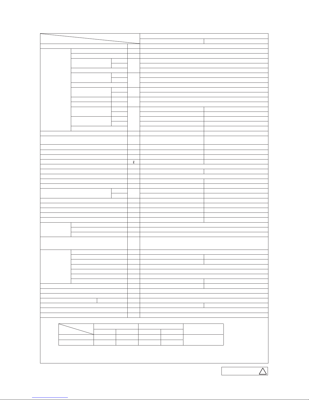
Model
Item
SRK60ZMX-S
Indoor unit SRK60ZMX-S Outdoor unit SRC60ZMX-S
Power source Single phase, 220 - 240V, 50Hz
Operation
data
Nominal cooling capacity (range) kW 6.1 ( 1.1 (Min.) - 6.8 (Max.))
Nominal heating capacity (range) kW 6.8 ( 0.6 (Min.) - 8.2 (Max.))
Power
consumption
Cooling
kW
1.87 ( 0.2 - 2.50 )
Heating 1.67 ( 0.2 - 2.70 )
Max power consumption 2.9
Running
current
Cooling
A
8.6 / 8.2 / 7.9 (220/ 230/ 240 V)
Heating 7.7 / 7.3 / 7.0 (220/ 230/ 240 V)
Inrush current, max current 8.6 / 8.2 / 7.9 (220/ 230/ 240 V) Max. 15
Power factor
Cooling
%
99
Heating 99
EER Cooling 3.26
COP Heating 4.07
Sound power level
Cooling
dB(A)
64 65
Heating 64 64
Sound pressure level
Cooling Hi: 51 Me: 41 Lo: 29 ULo: 25 54
Heating Hi: 48 Me: 41 Lo: 34 ULo: 27 54
Silent mode sound pressure level — Cooling:45 / Heating:45
Exterior dimensions (Height x Width x Depth) mm 309 x 890 x 220 640 x 800(+71) x 290
Exterior appearance
( Munsell color )
Fine snow
( 8.0Y 9.3/0.1 ) near equivalent
Stucco white
( 4.2Y 7.5/1.1 ) near equivalent
Net weight kg 13.5 45
Compressor type & Q'ty — RMT5113MCE2( Twin Rotary type ) x 1
Compressor motor (Starting method) kW — 1.50 ( Inverter driven )
Refrigerant oil (Amount, type) — 0.45 (DIAMOND FREEZE MA68)
Refrigerant (Type, amount, pre-charge length) kg R410A 1.5 in outdoor unit (incl. the amount for the piping of 15m )
Heat exchanger Louver fins & inner grooved tubing M fins & inner grooved tubing
Refrigerant control Capillary tubes + Electronic expansion valve
Fan type & Q'ty Tangential fan x 1 Propeller fan x 1
Fan motor (Starting method) W 30 x1 (Direct drive) 34 x1 (Direct drive)
Air flow
Cooling
m3/min
Hi: 14.5 Me: 12.5 Lo: 8.5 ULo: 7.0 41.5
Heating Hi: 17.5 Me: 15.0 Lo: 11.0 ULo: 8.5 39.0
Available external static pressure Pa 0 0
Outside air intake Not possible —
Air filter, Quality / Quantity Polypropylene net ( washable ) x 2 —
Shock & vibration absorber Rubber sleeve (for fan motor) Rubber sleeve (for fan motor & compressor)
Electric heater — —
Operation
control
Remote control Wireless remote control
Room temperature control Microcomputer thermostat
Operation display RUN: Green, TIMER: Yellow, HI POWER: Green, 3D AUTO: Green, ECONO: Blue
Safety equipments
Compressor overheat protection, Overcurrent protection,
Frost protection, Serial signal error protection, Indoor fan motor error protection,
Heating overload protection (High pressure control), Cooling overload protection
Installation
data
Refrigerant piping size (O.D) mm Liquid line :φ6.35 (1/4") Gas line :φ12.7 (1/2")
Connecting method Flare connection Flare connection
Attached length of piping m Liquid line : 0.55 / Gas line : 0.49 —
Insulation for piping Necessary (Both sides), independent
Refrigerant line (one way) length m Max. 30
Vertical height diff. between O.U. and I.U.
m Max. 20 (Outdoor unit is higher) / Max. 20 (Outdoor unit is lower)
Drain hose
Hose connectable ( VP 16 ) Holes φ20 x 5 pcs
Drain pump, max lift height mm — —
Recommended breaker size A 16
L.R.A. (Locked rotor ampere) A 8.6 / 8.2 / 7.9 (220/ 230/ 240 V)
Interconnecting wires Size x Core number 1.5mm2 x 4 cores (Including earth cable) / Terminal block (Screw fixing type)
IP number IPX0 IPX4
Standard accessories
Mounting kit, Clean filter (Allergen clear filter x 1, Photocatalytic washable deodorizing filter x 1)
Option parts Interface kit (SC-BIKN-E)
Note (1) The data are measured at the following conditions.
Item
Operation
Indoor air temperature Outdoor air temperature
Standards
DB WB DB WB
Cooling 27˚C 19˚C 35˚C 24˚C
ISO5151-T1
Heating 20˚C — 7˚C 6˚C
(2) This air-conditioner is manufactured and tested in conformity with the ISO.
(3) Sound level indicates the value in an anechoic chamber. During operation these value are somewhat higher
due to ambient conditions.
(4) Select the breaker size according to the own national standard.
The pipe length is 7.5m.
B
RWA000Z252
-
7
-
'13 • SRK-T-144D
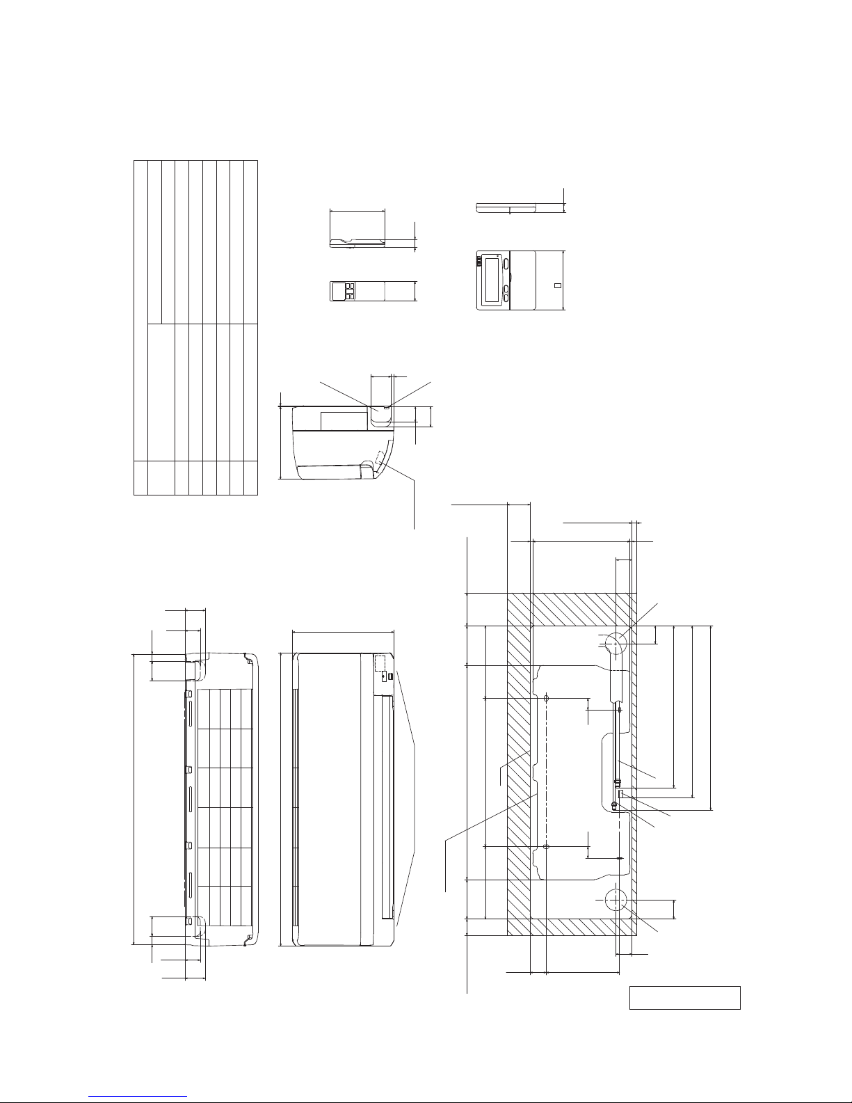
2. EXTERIOR DIMENSIONS
(1) Indoor units
Models SRK20ZMX-S, 25ZMX-S, 35ZMX-S, 50ZMX-S, 60ZMX-S
RKY000Z058
881.9
59.9
26
61.5
46.5
59.9
20.9
46.5
61.5
890
309
Outlet for down piping
(Refer to the above view)
(Service space)
Installation plate
50
120
220
48.9
222.5
48
58
D
B
E
35
35
650
450
120
100
220
7.9
70
295.4
5.7
48
54
C
491.1
520.8
559.1
A
46.5
19
60
24
61.5
120
9
61.5
F
G
3
220
Space for installation and service when viewing from the front
Unit
15(Service space)
(Service space)
(Service space)
Terminal block
Wired - remote control
(Option)
Notes(1)The model name label is attached
on the underside of the panel.
(2)It takes the interface kit (SC-BIKN-E)
to connect the wired remote controller.
Unit:mm
Wireless remote control
Hole on wall for right rear piping
Hole on wall for left rear piping
Gas piping
Outlet for wiring
Drain hose
Liquid piping
F
E
C
D
B
Symbol
A
(φ65)
VP16
φ6.35(1/4")(Flare)
Content
(φ65)
Outlet for piping(on both side)G
φ9.52(3/8")(Flare)
φ12.7(1/2")(Flare)
Model 20,25,35
Model 50,60
167
-
8
-
'13 • SRK-T-144D
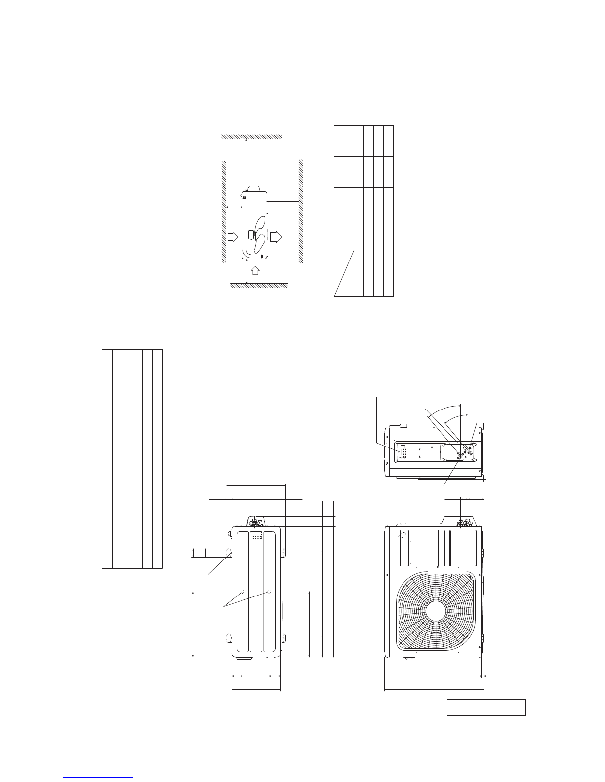
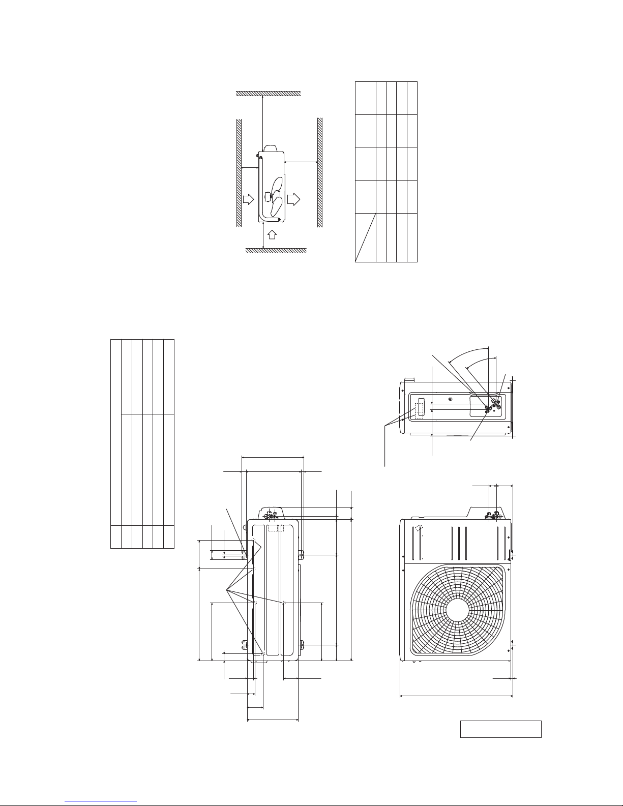
(2) Outdoor unit
Models SRC20ZMX-S, 25ZMX-S, 35ZMX-S
RCV000Z020
( )
φ
9.52(3/8")(Flare)
Content
C
Pipe/cable draw-out hole
E
Anchor bolt hole
Drain discharge hole
Symbol
B
A
Service valve connection(gas side)
M10×4places
φ
20×2places
Service valve connection(liquid side)
φ
6.35(1/4")(Flare)
D
390.6
D
63.4
290
69.4
E
50.6
12
24.3
312.5
351.6
14.8
17.9
61.9
158.4
510
780
390.6
111.6
390.6
595
15.8
97.7
42.5
B
138.4
33.5
C
40°
40
°
A
Terminal block
L2L3L4
L1
100
100
250
Open
I II
Open
250
80
280
III
280
Open
80
75
Examples of
Dimensions
installation
IV
180
Open
80
Open
Notes
(1) It must not be surrounded by walls on the four sides.
(2) The unit must be fixed with anchor bolts. An anchor bolt must not
protrude more than 15mm.
(3) Where the unit is subject to strong winds, lay it in such
a direction that the blower outlet faces perpendicularly
to the dominant wind direction.
(4) Leave 1m or more space above the unit.
(5) A wall in front of the blower outlet must not exceed the units height.
(6) The model name label is attached on the lower right corner of the front panel.
Minimum installation space
Unit:mm
L2
Intake
Outlet
Intake
L3
L1
Service
space
L4
-
9
-
'13 • SRK-T-144D
RCT000Z010
Models SRC40ZMX-S, 50ZMX-S, 60ZMX-S
φ
12.7(1/2")(Flare)
Content
C
Pipe/cable draw-out hole
D
E
Anchor bolt hole
Drain discharge hole
Symbol
B
A
Service valve connection(gas side)
M10×4places
φ
20×5places
Service valve connection(liquid side)
φ
6.35(1/4")(Flare)
520.6
161
50.6
12
E
24.3
312.5
351.6
14.8
17.9
71.2
201
800
510
327.3
89
83.5
290
90.6
43.5
35.6
38.6
327.3
D
640
12.4
93
42.5
148.4
B
33.5
C
A
40
°
40
°
Terminal block
Notes
(1) It must not be surrounded by walls on the four sides.
(2) The unit must be fixed with anchor bolts. An anchor bolt must not
protrude more than 15mm.
(3) Where the unit is subject to strong winds, lay it in such
a direction that the blower outlet faces perpendicularly
to the dominant wind direction.
(4) Leave 1m or more space above the unit.
(5) A wall in front of the blower outlet must not exceed the units height.
(6) The model name label is attached on the right side of the unit.
L2
Intake
Outlet
Intake
L3
L1
Minimum installation space
L4
( )
Service
space
L2L3L4
L1
100
100
250
Open
I
II
Open
250
80
280
III
280
Open
80
75
Examples of
Dimensions
installation
IV
180
Open
80
Open
Unit:mm
-
10
-
'13 • SRK-T-144D
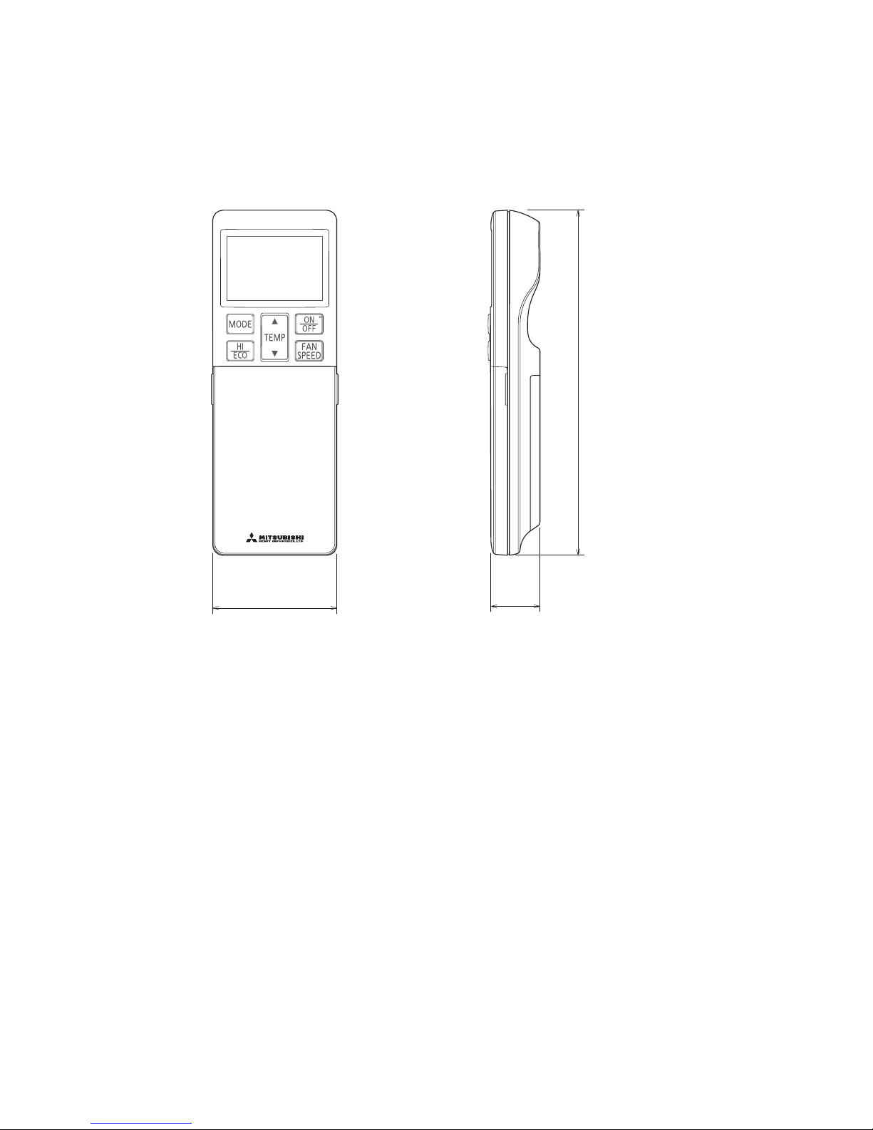
(3) Remote control
Unit : mm
60
26
167
-
11
-
'13 • SRK-T-144D
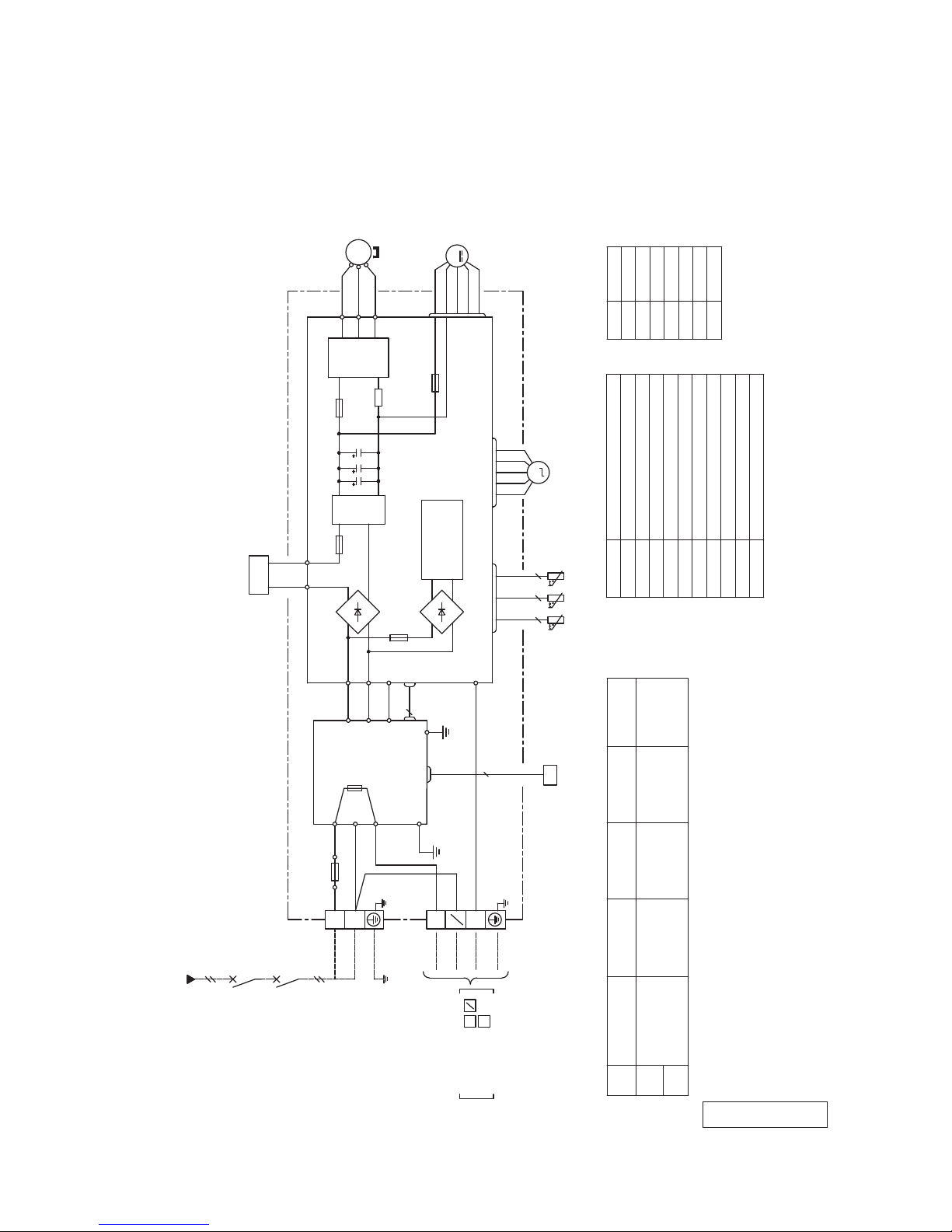
250V
F
G
3.15A
S/N
CNU
CNS
INTERFACE KIT
SC-BIKN-E
CNG
CNE
DISPLAY
WIRELESS RECEIVER
J
CNF
M
HEAT
13456
BACK-UP SW
5
2
12
EXCHANGER
L
Th1
BOARD
CIRCUIT
PRINTED
LS
CNY
CNX2
CNX1
M
M
M
M
5
5
5
5
5
5
5
5 5
RD
WH
RD
WHBKBL
Y
Y/G
BK
Color Marks
Blue
BlackBK
Red
BL
RD
WhiteWH
Yellow/GreenY/G
YellowY
ColorMark
t
Th2
1
Th2
2
Th3
LM1LM
2
SM
FM
I
Heat exch. sensor
Humidity sensor (50, 60 only)
Fan motor
Room temp. sensor
Flap motor
Th1
Th2
Th3
Diode stackDS
FuseF
FM
I
Terminal blockT
Louver motor
LM
1,2
SM
DS
1,2
Limit switchLS
Inlet motor
IM
Description
Item
VaristorVa
t
t
TO OUTDOOR UNIT
HEAT
EXCHANGER
1
2/N
3
POWER WIRES
SIGNAL WIRE
1
2/N
3
Power source
1 Phase 220 - 240V 50Hz
T
IM
Va
U
CNE-CNY
Connector
3. ELECTRICAL WIRING
(1) Indoor units
Models SRK20ZMX-S, 25ZMX-S, 35ZMX-S, 50ZMX-S, 60ZMX-S
RWA000Z258
-
12
-
'13 • SRK-T-144D
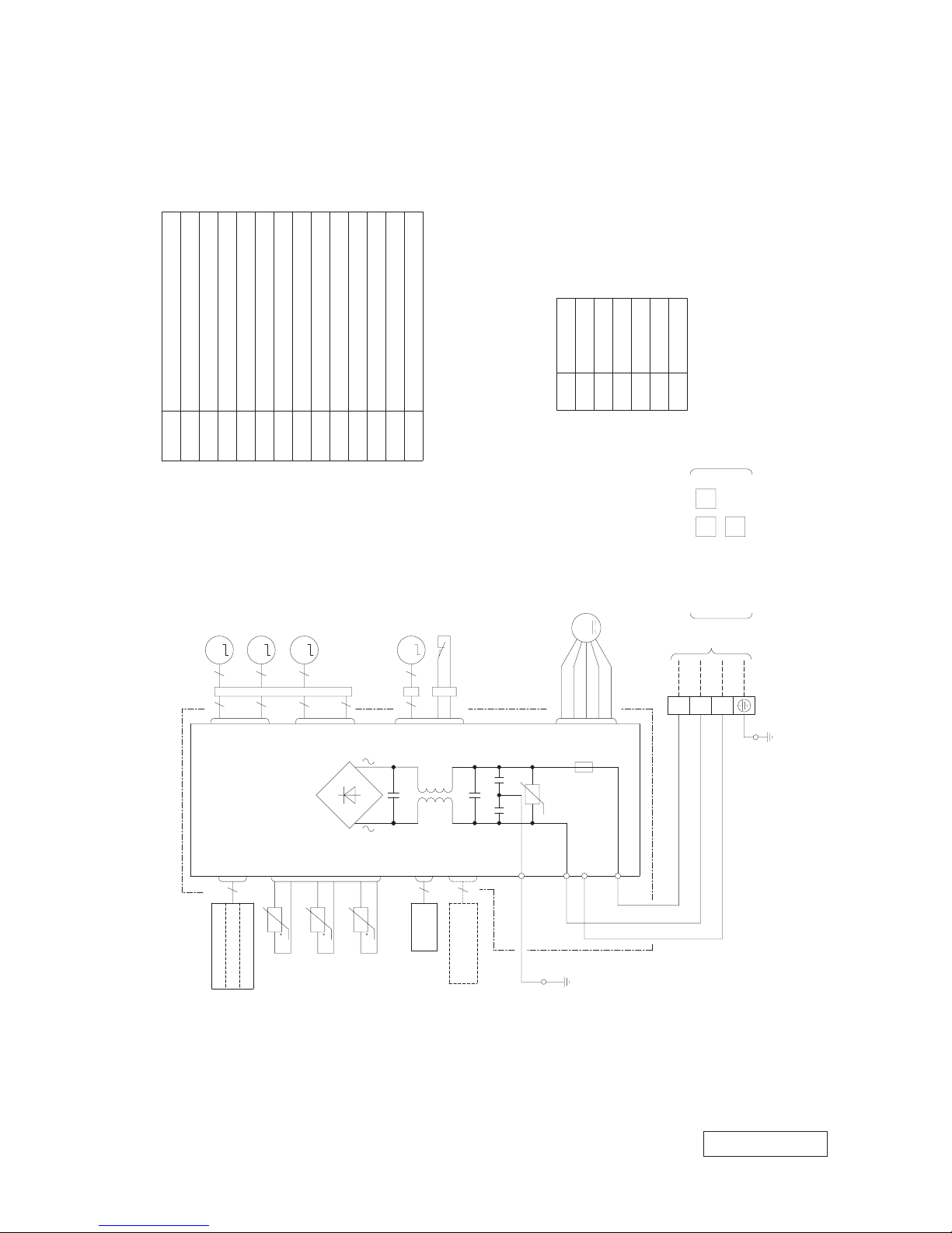
(2) Outdoor unit
Models SRC20ZMX-S, 25ZMX-S, 35ZMX-S
RWC000Z272
Description
Item
Connector
Electric expansion valve(coil)
EEV
Fan motorFMo
ReactorL
Terminal blockTB1
Compressor motorCM
Solenoid valve for 4 way valve20S
Heat exchanger sensor(outdoor unit)
TH2
Outdoor air temp.sensorTH3
TH4 Discharge pipe temp.sensor
CN20S
CNTH
CNEEV
CNFAN
Color
RD
Mark
OrangeOR
Yellow/Green
Y/G
BlackBKYellowY
WhiteWH
Red
Power cable, indoor-outdoor connecting wires
・The specifications shown in the above table are for units without heaters. For units with heaters, refer
to the installation instructions or the construction instructions of the indoor unit.
・Switchgear of Circuit breaker capacity which is calculated from MAX. over current should be chosen
along the regulations in each country.
・The cable specifications are based on the assumption that a metal or plastic conduit is used with no
more than three cables contained in a conduit and a voltage drop is 2%. For an installation falling
outside of these conditions, please follow the internal cabling regulations. Adapt it to the regulation
in effect in each country.
20
Model
MAX running current
Power cable size
(mm )
2
(A)
Power cable length
(m)
indoor-outdoor
wire size x number
Earth wire size
25
2.0
32
35
1.5mm x 3
2
9(ZM)
8(ZMX)
1.5
(mm )
2
3
1
2
TO INDOOR UNIT
POWER WIRES
SIGNAL WIRE
N
POWER SOURCE
TB1
TERMINAL
BLOCK
L
N
132
(BK)
R.IN
250V 15A
(BK)
(WH)
(Y/G)
(Y/G)
(Y/G)
(RD)
C-2G1G2
S.IN
FILTER
NOISE
F1
250V 3.15A
T1
T2
(OR)
(Y)
L
20S
2
2 2 2
CN20S CNTH CNEEV
TH2 TH3 TH4
M
EEV
CIRCUIT
POWER
SWITCHING
F4
250V 10A
CIRCUIT
PAM
250V 20A
F2
PWB ASSY PWB1
TRANSISTOR
POWER
(BK)
(WH)
(RD)
N
P
W
V
U
W
V
U
M
3~
CM
F3 250V 1A
CNFAN
FMo
M
〜220ー240V 50Hz/〜220V 60Hz
-
13
-
'13 • SRK-T-144D
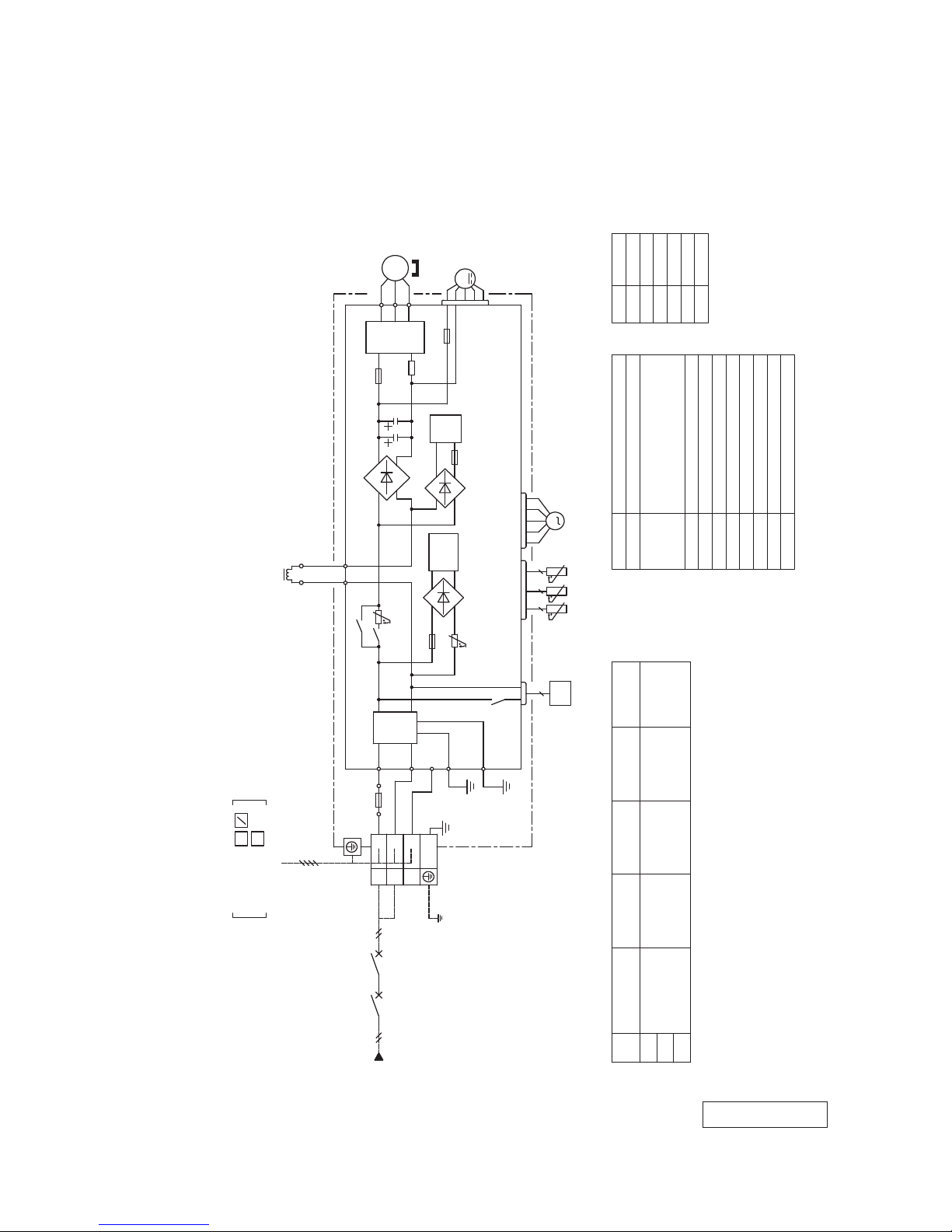
Models SRC50ZMX-S, 60ZMX-S
RWC000Z270
Description
Item
Connector
CNEEV~CN20S
Electric expansion valve(coil)
EEV
Fan motorFMo
ReactorR
Terminal blockTB1,2
Compressor motorCM
Solenoid valve for 4 way valve20S
Heat exchanger sensor(outdoor unit)
TH2
Outdoor air temp.sensorTH3
TH4 Discharge pipe temp.sensor
Color
RD
Mark
Orange
OR
Yellow/Green
Y/G
BlackBKBrownBRYellow
YE
White
WH
Red
・The specifications shown in the above table are for units without heaters. For units with heaters, refer
to the installation instructions or the construction instructions of the indoor unit.
・Switchgear of Circuit breaker capacity which is calculated from MAX. over current should be chosen
along the regulations in each country.
・The cable specifications are based on the assumption that a metal or plastic conduit is used with no
more than three cables contained in a conduit and a voltage drop is 2%. For an installation falling
outside of these conditions, please follow the internal cabling regulations. Adapt it to the regulation
in effect in each country.
15 2.0 18 1.5
50
60
1.5mm x 3
2
Power cable, indoor-outdoor connecting wires
Model
MAX running current
Power cable size
2
(A)
Power cable length
(m)
indoor-outdoor
wire size x number
Earth wire size
(mm )
(mm )
2
POWER SOURCE
~220-240V 50Hz
TO INDOOR UNIT
POWER WIRES
SIGNAL WIRE
3
1
2
N
TB1
TERMINAL
BLOCK
L
N
TB2
BLOCK
TERMINAL
1
2
N
3
(Y/G)
(Y/G)
(Y/G)
(Y/G)
20S
2
TH2 TH3 TH4
2 2 2
CNTH
M
EEV
R
S
(BK)
IN
IN
FUSE
(BK)
250V 20A
(WH)
(BR)
(WH)
R
OUT
PWB ASSY (SUB)
250V 10A
G1
CN20S
F10
S
R
250V 3.15A
F1
S-2
(BK)
(WH)
(WH)
(BK)
S-1
CNSUB
CNMAIN
S
O
R
O
G3
4
C-2
(RD)
T2
T1
(OR)
(YE)
R
PWB ASSY (MAIN)
F8
F2
250V 20A 250V 20A
CIRCUIT
SWITCHING POWER
CNEEV
ACTIVE
FILTER
UNIT
F3 250V 1A
TRANSISTOR
POWER
N
P
W
V
U
CNFAN
(BK)
(WH)
(RD)
W
V
U
MS
3~
CM
FMo
M
-
14
-
'13 • SRK-T-144D
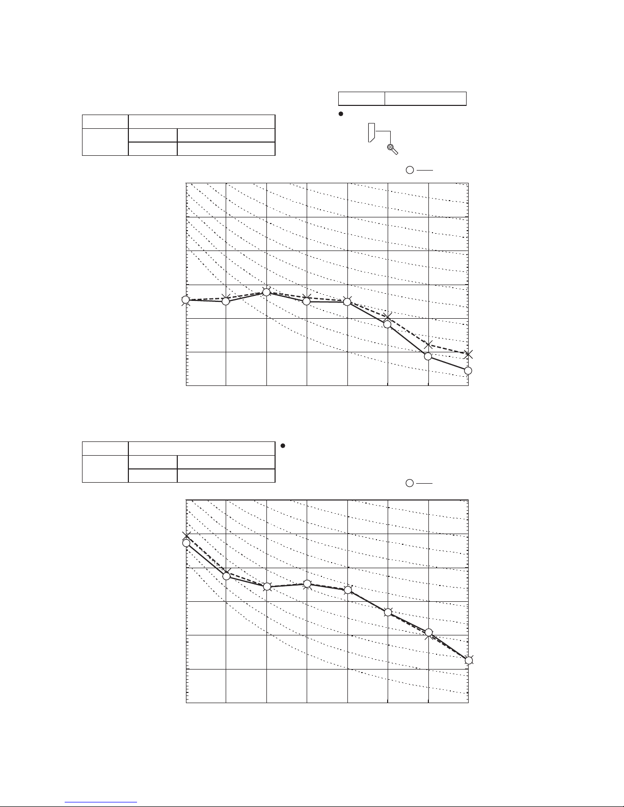
(Indoor Unit)
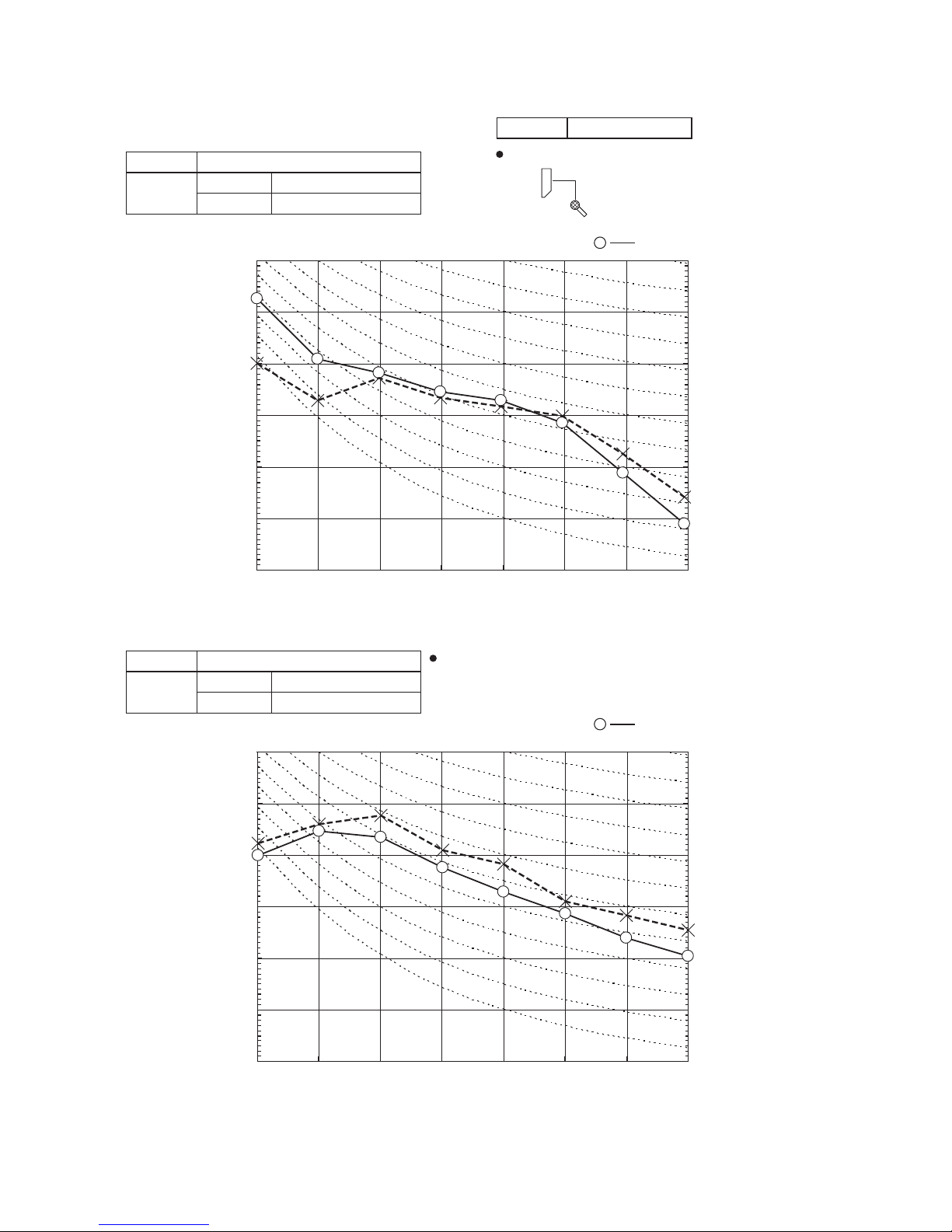
Model SRK20ZMX-S
Noise
Level
Cooling 39 dB(A)
Heating 38 dB(A)
×
......
Cooling, Heating
10
20
30
40
50
60
70
63 125 250 500 1000 2000 4000 8000
Mid Octave Band frequency (Hz)
Sound Pressure Level (dB)
(standard 2×10
-5
Pa )
10
20
30
40
50
60
70
N50
N30
N40
N60
N70
N20
(Outdoor Unit)
Model SRC20ZMX-S
Noise
Level
Cooling 47 dB(A)
Heating 47 dB(A)
10
20
30
40
50
60
70
63 125 250 500 1000 2000 4000 8000
Mid Octave Band frequency (Hz)
Sound Pressure Level (dB)
(standard 2×10
-5
Pa )
10
20
30
40
50
60
70
N50
N40
N60
N70
N20
N30
×
......
Cooling, Heating
Condition ISO-T1,JIS C 9612
Mike position: at highest noise level in position as mentioned below
Distance from front side 1m
Mike position
0.8m
1m
Unit
Mike position
(Center & Low points)
Mike position
0.8m
1m
Unit
Mike position
(Center & Low points)
4. NOISE LEVEL
Model SRK20ZMX-S
-
15
-
'13 • SRK-T-144D
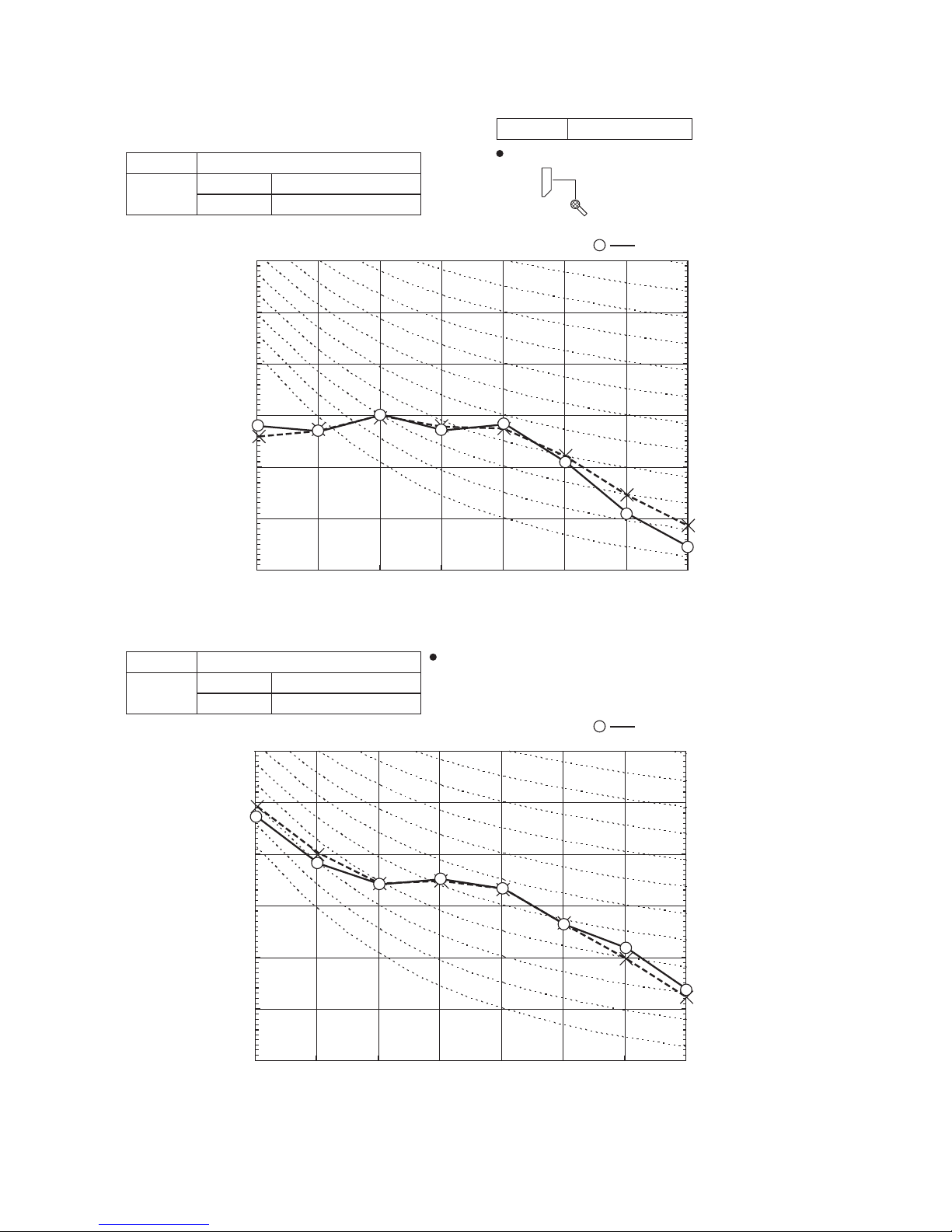
(Indoor Unit)
Model SRK25ZMX-S
Noise
Level
Cooling 41 dB(A)
Heating 41 dB(A)
×
......
Cooling, Heating
Model SRK25ZMX-S
10
20
30
40
50
60
70
63 125 250 500 1000 2000 4000 8000
Mid Octave Band frequency (Hz)
Sound Pressure Level (dB)
(standard 2×10
-5
Pa )
10
20
30
40
50
60
70
N50
N30
N40
N60
N70
N20
(Outdoor Unit)
Model SRC25ZMX-S
Noise
Level
Cooling 47 dB(A)
Heating 47 dB(A)
10
20
30
40
50
60
70
63 125 250 500 1000 2000 4000 8000
Mid Octave Band frequency (Hz)
Sound Pressure Level (dB)
(standard 2×10
-5
Pa )
10
20
30
40
50
60
70
N50
N40
N60
N70
N20
N30
×
......
Cooling, Heating
Condition ISO-T1,JIS C 9612
Mike position: at highest noise level in position as mentioned below
Distance from front side 1m
Mike position
0.8m
1m
Unit
Mike position
(Center & Low points)
Mike position
0.8m
1m
Unit
Mike position
(Center & Low points)
-
16
-
'13 • SRK-T-144D
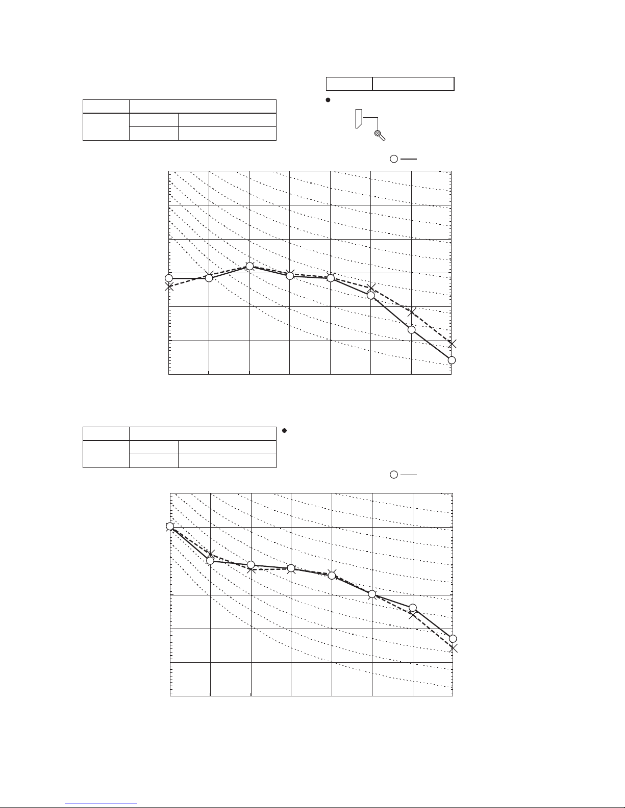
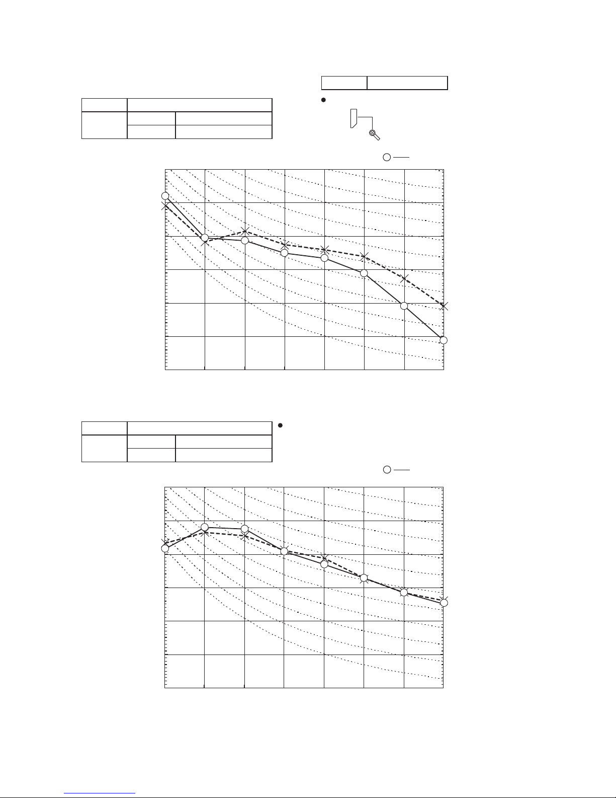
(Indoor Unit)
Model SRK35ZMX-S
Noise
Level
Cooling 43 dB(A)
Heating 42 dB(A)
×
......
Cooling, Heating
Model SRK35ZMX-S
(Outdoor Unit)
Model SRC35ZMX-S
Noise
Level
Cooling 50 dB(A)
Heating 50 dB(A)
×
......
Cooling, Heating
Condition ISO-T1,JIS C 9612
10
20
30
40
50
60
70
63 125 250 500 1000 2000 4000 8000
Mid Octave Band frequency (Hz)
Sound Pressure Level (dB)
(standard 2×10
-5
Pa )
10
20
30
40
50
60
70
N50
N30
N40
N60
N70
N20
10
20
30
40
50
60
70
63 125 250 500 1000 2000 4000 8000
Mid Octave Band frequency (Hz)
Sound Pressure Level (dB)
(standard 2×10
-5
Pa )
10
20
30
40
50
60
70
N50
N30
N40
N60
N70
N20
Mike position: at highest noise level in position as mentioned below
Distance from front side 1m
Mike position
0.8m
1m
Unit
Mike position
(Center & Low points)
Mike position
0.8m
1m
Unit
Mike position
(Center & Low points)
-
17
-
'13 • SRK-T-144D
Mike position
0.8m
1m
Unit
Mike position
(Center & Low points)
(Indoor Unit)
Model SRK50ZMX-S
Noise
Level
Cooling 47 dB(A)
Heating 48 dB(A)
×
......
Cooling, Heating
Model SRK50ZMX-S
(Outdoor Unit)
Model SRC50ZMX-S
Noise
Level
Cooling 54 dB(A)
Heating 50 dB(A)
×
......
Cooling, Heating
Condition ISO-T1, JIS C 9612
10
20
30
40
50
60
70
63 125 250 500 1000 2000 4000 8000
Mid Octave Band frequency (Hz)
Sound Pressure Level (dB)
(standard 2×10
-5
Pa )
10
20
30
40
50
60
70
N50
N30
N40
N60
N70
N20
10
20
30
40
50
60
70
63 125 250 500 1000 2000 4000 8000
Mid Octave Band frequency (Hz)
Sound Pressure Level (dB)
(standard 2×10
-5
Pa )
10
20
30
40
50
60
70
N50
N30
N40
N60
N70
N20
Mike position: at highest noise level in position as mentioned below
Distance from front side 1m
Mike position
0.8m
1m
Unit
Mike position
(Center & Low points)
-
18
-
'13 • SRK-T-144D
(Indoor Unit)
Model SRK60ZMX-S
Noise
Level
Cooling 51 dB(A)
Heating 48 dB(A)
×
......
Cooling, Heating
Model SRK60ZMX-S
(Outdoor Unit)
Model SRC60ZMX-S
Noise
Level
Cooling 54 dB(A)
Heating 54 dB(A)
×
......
Cooling, Heating
Condition ISO-T1, JIS C 9612
10
20
30
40
50
60
70
63 125 250 500 1000 2000 4000 8000
Mid Octave Band frequency (Hz)
Sound Pressure Level (dB)
(standard 2×10
-5
Pa )
10
20
30
40
50
60
70
N50
N30
N40
N60
N70
N20
10
20
30
40
50
60
70
63 125 250 500 1000 2000 4000 8000
Mid Octave Band frequency (Hz)
Sound Pressure Level (dB)
(standard 2×10
-5
Pa )
10
20
30
40
50
60
70
N50
N30
N40
N60
N70
N20
Mike position: at highest noise level in position as mentioned below
Distance from front side 1m
Mike position
0.8m
1m
Unit
Mike position
(Center & Low points)
Mike position
0.8m
1m
Unit
Mike position
(Center & Low points)
 Loading...