

Mitsubishi Electric US, Inc RM1200DG-66S Data Sheet
MITSUBISHI HIGH VOLTAGE DIODE MODULE
RM1200DG-66S
High Voltage Diode Module
HIGH POWER SWITCHING USE
RM1200DG-66S
● IF ................................................................ 1200A
● V
RRM ...................................................... 3300V
● High Insulated Type
● 2-element in a Pack
● AlSiC Baseplate
APPLICATION
Traction drives, High Reliability Converters / Inverters, DC choppers
INSULATED TYPE
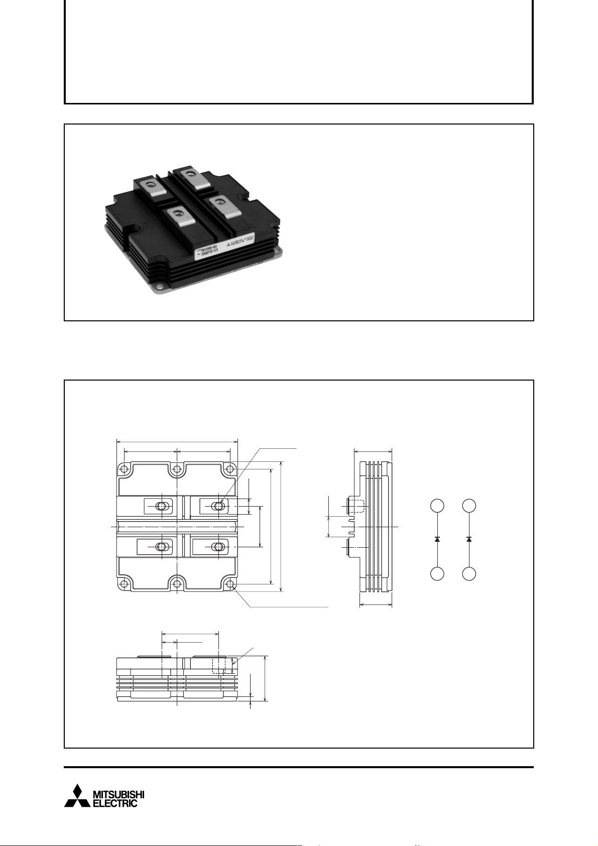
OUTLINE DRAWING & CIRCUIT DIAGRAM Dimensions in mm
130
>PET+PBT<
57
±0.5
±0.25
57
±0.25
42
3
61.2
±0.5
16.5
±0.3
1
4-M8 NUTS
±0.1
17
±0.5
±0.25
±0.3
44
140
124
6-φ7 MOUNTING HOLES
Screwing depth
min. 16.5
+1.0
0
±0.15
48
5
40.4
±0.5
±0.3
22
34.4
±0.5
(K)
4
3
CIRCUIT DIAGRAM
2
(K)
(A)
1
(A)
High Voltage Diode Module
May 2009
1
MITSUBISHI HIGH VOLTAGE DIODE MODULE
RM1200DG-66S
HIGH POWER SWITCHING USE
High Voltage Diode Module
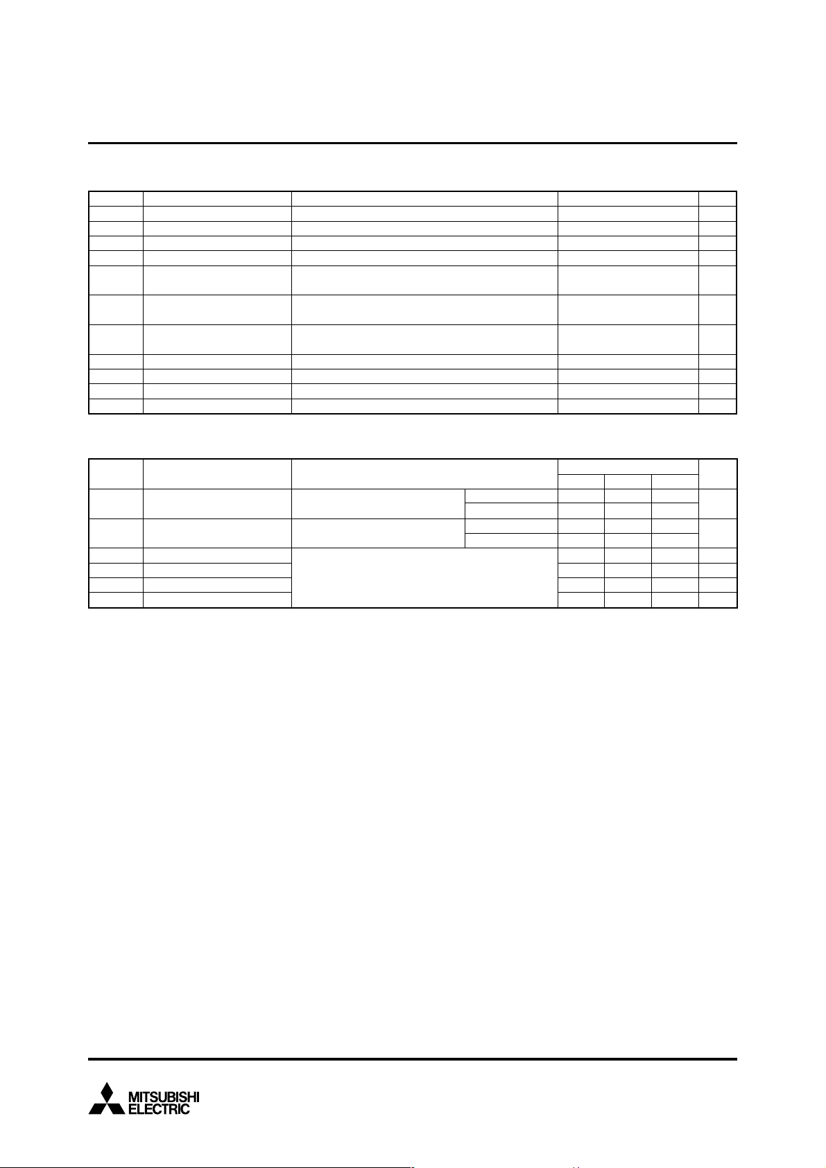
MAXIMUM RATINGS
Symbol Item Conditions UnitRatings
V
RRM
VRSM
VR(DC)
IF
IFSM
I2t
iso
V
Ve
Tj
Top
Tstg
ELECTRICAL CHARACTERISTICS
Symbol
I
RRM
VFM
trr
Irr
Qrr
Erec
Repetitive peak reverse voltage
Non-repetitive peak reverse voltage
Reverse DC voltage
DC forward current
Surge forward current
Current-squared, time integration
Isolation voltage
Partial discharge extinction voltage
T
T
T
T
T
Half sign wave
T
Half sign wave
Charged part to the baseplate
RMS sinusoidal, 60Hz 1min.
RMS sinusoidal, 60Hz, Q
Junction temperature
Operating temperature
Storage temperature
Item
Repetitive reverse current
Forward voltage (Note 1)
Reverse recovery time
Reverse recovery current
Reverse recovery charge
Reverse recovery energy (Note 2)
VRM = VRRM
IF = 1200 A
VR = 1650 V, IF = 1200 A
di/dt = –4000 A/µs
L
j = 25 °C
j = 25 °C
j = 25 °C
C = 25 °C
j = 25 °C start, tw = 8.3 ms
j = 25 °C start, tw = 8.3 ms
Conditions
s=100nH, Tj = 125 °C
PD ≤ 10PC
—
—
—
T
j = 25 °C
T
j = 125 °C
j = 25 °C
T
T
j = 125 °C
10200
–40 ~ +150
–40 ~ +125
–40 ~ +125
Limits
Min
—
—
—
—
—
—
—
—
INSULATED TYPE
3300
3300
2200
1200
9600
384
5100
Typ Max
—
3
2.80
2.70
1.0
1600
800
0.9
kA
5
30
—
—
—
—
—
—
V
V
V
A
A
V
V
°C
°C
°C
Unit
mA
V
µs
A
µC
J/P
2
s
Note 1. It doesn't include the voltage drop by internal lead resistance.
2. E
rec is the integral of 0.1VR
x
0.1Irr x dt.
High Voltage Diode Module
May 2009
2
 Loading...