

Mitsubishi Electric US, Inc PSS35MC1FT Data Sheet
P
<
P
TIN
D
L
3
D
r
a
C
b
a
T
O
i
i
p
h
i
7
a
i
O
A
i
s
i
o
C
L
i
5
A
w
e
e
h
-
t
-
I
C
e
F
i
t
e
V
g
C
C
r
I
c
C
p
t
n
s
e
e
0
t
m
n
)
e
0
t
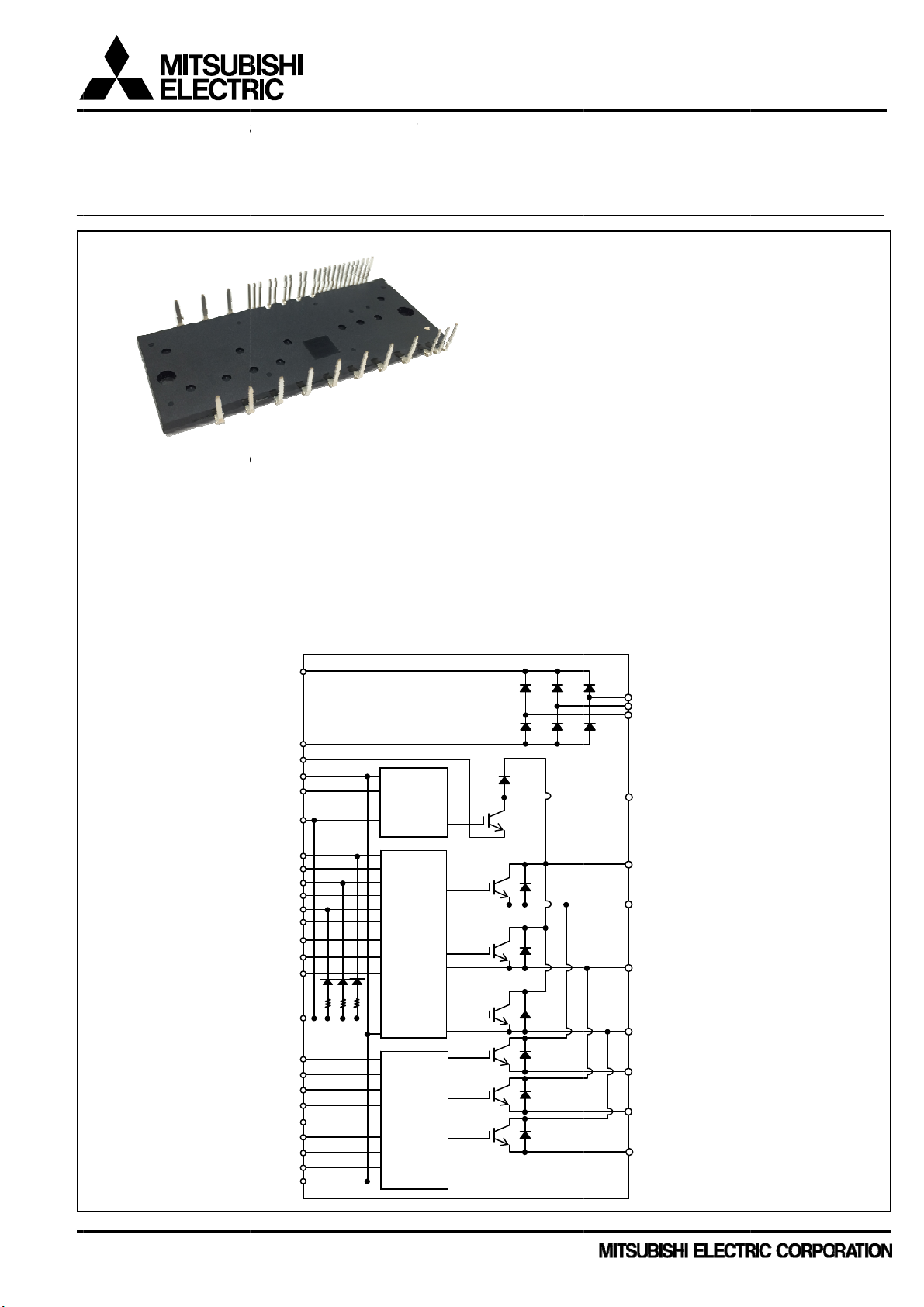
Dual-In-
ine Pack
ge Intell
gent Po
er Modul
>
SS
RANSFER
SULATED
OUTLINE
INTEGRATE
● For P-side
● For N-side
● Fault signa
● Temperatu
● Input interf
● For Brake
● UL Recogn
INTERNAL
5MC
MOLDING
TYPE
DRIVE, PR
: Drive c
Control
Built-in
: Drive c
Short c
ling : Corres
e monitoring
ce : 5V hig
: Drive c
ized : UL155
IRCUIT
1FT
YPE
TECTION
rcuit, High vo
supply under
discrete boot
rcuit, Control
ircuit protecti
onding to S
: Outputting
active logic
rcuit, Control
File E323
P1 (1)
N1 (2)
N(B) (3)
VNC (4)
IN (5)
VP1 (6)
V
(7)
UFB
V
(8)
UFS
(9)
V
VFB
V
(10)
VFS
V
(11)
WFB
V
(12)
WFS
(13)
U
P
V
(14)
P
WP (15)
VP1 (16)
UN (17)
VN (18)
WN (19)
Fo (20)
VOT (21)
CIN (22)
CFo (23)
VN1 (24)
VNC (25)
ND SYSTEM
ltage high-sp
-voltage prot
trap diode c
supply under
n (SC) by de
fault (N-side
VIC temperat
supply under
85
LVI
HV
LVI
CONTROL
ed level shift
ction (UV) wi
ips with curre
voltage prote
ecting voltag
IGBT) and U
ure by analo
voltage prote
C
C
MAIN FUN
CIB(Conve
3-phase
Brake cir
3-phase
RATING
Inverter
APPLICAT
AC400V
UNCTIONS
ng,
hout fault sig
nt limiting res
ction (UV),
of external
fault (N-sid
signal (No s
ction (UV) wit
TION
ter + Inverter
nverter
uit
onverter
art : 35A/120
ION
hree phase
al output
istor
hunt resistor
supply)
lf over tempe
hout fault sig
R (36)
S (35)
T (34)
B (33)
P (32)
U (31)
V (30)
W (29)
NU (28
NV (27)
NW (26
+ Brake) typ
V (CSTBT)
otor inverter
rature protec
al output
)
IPM
drive
ion)
ublication
ate : Octo
er 2016
1
<PTIN
P
MINBC
C
N
Dual-In-Li
n
M
D
A
A
u
u
o
a
a
u
T
u
u
o
a
a
e
o
o
u
e
C
u
2
t
u
R
o
o
a
a
u
h
T
b
5
a
s
c
c
a
a
s
c
c
e
(
a
a
e
a
)
a
o
o
p
e
m
P
5
a
a
t
u
C
C
C
C
C
e
a
o
r
,
,
C
C
m
B
B
C
C
m
C
f
e
g
P
U
P
O
i
C
V
o
o
a91
1
o
0Ra91
1
o
1
0Ra13
5-30Ra
~
~
~
U
9
U
9
U
3
5
A
U
m
SS35
RANSFER
SULATED
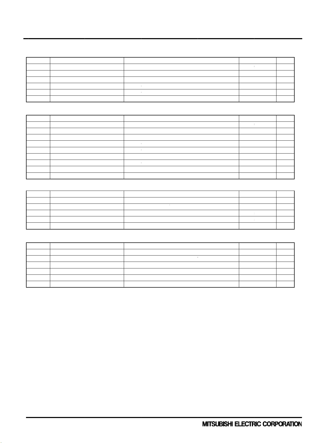
AXIMUM R
VERTER P
Symbol
V
CC
V
CC(surge)
V
C
CES
±IC E
±ICP E
Tj J
RAKE PAR
Symbol
V
CC
V
CC(surge)
V
C
CES
IC E
ICP E
V
R
RRM
IF F
IFP F
Tj J
ONVERTER
Symbol
V
RRM
Io
I
FSM
I2t
Tj
ONTROL (P
Symbol
VD C
VDB C
VIN In
VFO F
IFO F
VSC C
ote1: Pulse widt
e Package
C1FT
MOLDING
TYPE
TINGS
RT
S
pply voltage
S
pply voltage (
llector-emitter
ch IGBT colle
ch IGBT colle
nction temper
S
pply voltage
S
pply voltage (
llector-emitter
ch IGBT colle
ch IGBT colle
petitive peak r
rward current
rward current
nction temper
PART
petitive peak r
R
output curren
D
rge forward cu
S
capability
I
nction temper
J
OTECTION
ntrol supply v
ntrol supply v
put voltage
ult output sup
ult output curr
rrent sensing i
and period are li
(Tj = 2
Intelligent
YPE
°C, unless oth
Par
meter
urge)
voltage
tor current
tor current (pe
ture
Par
meter
urge)
voltage
tor current
tor current (pe
verse voltage
peak)
ture
Par
meter
verse voltage
t
rrent
ture
PART
Par
meter
ltage
ltage
ly voltage
nt
nput voltage
ited due to junc
erwise noted)
k) TC= 25°
k) TC= 25°
ion temperature.
ower Mod
Applied
Applied
TC= 25°
Applied
Applied
TC= 25°
TC= 25°
3-phas
Peak v
Value f
Applied
Applied
Applied
Applied
Sink cu
Applied
le >
between P-NU
between P-NU
, less than 1
between P-N(
between P-N(
, less than 1
full wave recti
lue of half cycl
r 1 cycle of sur
between V
between V
between U
between F
rent at FO term
between
Condition
NV,NW
NV,NW
s
Condition
)
)
s
Condition
ication
at 60Hz, Non-
e current
Condition
, VN1-VNC
1-VNC
, V
FB-VUFS
,VP,WP,UN, VN,
-VNC
nal
IN-VNC
repetitive
-
VFB
VFS
WN, AIN-VNC
, V
WFB-VWFS
R
tings
00
000
200
(N
te 1)
-3
(N
te 1)
-3
-0.5
-0.5
-0.5
35
70
~+150
tings
00
000
200
25
50
200
25
50
~+150
tings
600
35
50
10
~+150
tings
20
20
VD+0.5
VD+0.5
5
VD+0.5
V
V
V
A
A
°C
V
V
V
A
A
V
A
A
°C
V
A
A
°C
V
V
V
V
V
nit
nit
nit
2
nit
A
s
ublication
ate : Octo
er 2016
2
<PTIN
P
T
T
Dual-In-Li
n
M
D
E
e(S
o
t
o
m
e
E
J
w
a
v
G
T
b
a
u
o
t
s
T
e
e
e
g
P
m
y
.
nInBB
C
d
m
e
nPow
u
j
5
S
n
a
a
p
r
t
b
r
1
o
a
t
a
μ
u
e
p
m
m
h
-
-
t
k
y
tsu
c
e
y
SS35
RANSFER
SULATED
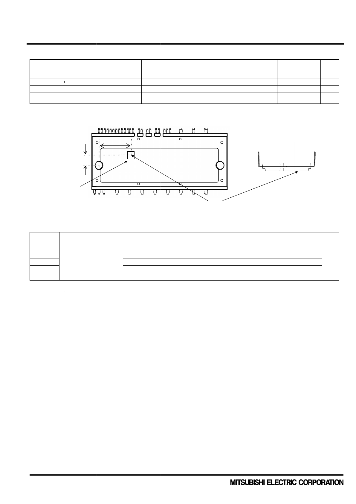
OTAL SYST
Symbol
V
CC(PROT)
TC M
T
S
stg
V
Is
iso
Note2: Measure
Fig. 1 Measur
S
e Package
C1FT
MOLDING
TYPE
M
lf protection s
hort circuit prot
dule case ope
orage tempera
lation voltage
ent point of Tc i
ment point of
6.4mm
I
BT chip
HERMAL R
Symbol
R
th(j-c)Q
R
th(j-c)F
R
th(j-c)Q
R
th(j-c)F
R
th(j-c)R
Note 3: Grease
DIPIPM
conducti
SISTANCE
unction to cas
r
esistance
ith good therma
nd heat sink. Th
ity of the applied
Par
Param
Intelligent
YPE
meter
pply voltage li
ection capabilit
ration temperat
ure
described in Fig
c
ter
thermal
(Note 3)
l conductivity an
contacting ther
rease. For refer
Co
19.6mm
ower Mod
V
it
)
ure
1.
trol terminals
er terminals
verter IGBT p
I
verter FWD p
rake IGBT part
rake FWD part
onverter part (
long-term endu
al resistance be
nce, Rth(c-f) is a
= 13
D
= 12
T
60Hz,
heat si
le >
.5~16.5V, Inve
°C, non-repetit
inusoidal, AC
k plate
Conditi
rt (per 1/6 mod
rt (per 1/6 mod
(per 1module)
(per 1module)
er 1/6module)
ance should be
ween DIPIPM c
out 0.25K/W (pe
Condition
ter Part
ive, less than 2
min, between
Tc point
n
ule)
le)
pplied evenly wi
se and heat sink
r 1chip, grease th
s
(Not
connected all
th about +100μ
Rth(c-f) is deter
ickness: 20μm, t
Ratings
800
2)
ins and
Hea
30~+110
40~+125
2500
radiation
rface
Limi
Min. Typ
- -
- -
- -
- -
- -
~+200μm on the
ined by the thic
ermal conductivit
s
. Max.
contacting surfa
ness and the th
: 1.0W/m•K).
0.95
1.30
1.15
1.30
1.10
Unit
V
Unit
K/W
e of
rmal
V
°C
°C
rms
ublication
ate : Octo
er 2016
3
<PTIN
P
EIN B C
Dual-In-Li
n
M
D
A
ovol
W
w
ocur
T
ovol
W
w
ocur
e
T
b
R
e
s
t
c
e
s
t
c
e
e
d
P
er
V
V
V
C
n
V
er
V
V
V
C
n
V
er
V
F
u
t
V
A
u
V
5
i
m
i
i
5
2
5
2
p
0
0
0
0
0
0
0
0
p
0
0
0
0
0
0
0
5
p
1
0
0
0
0
0
0
0
0
0
0
0
0
0
0
0
5
SS35
RANSFER
SULATED
LECTRICAL
VERTER P
Symbol
V
CE(sat)
VEC F
ton
t
C(on)
t
off
t
C(off)
trr
I
CES
e Package
C1FT
MOLDING
TYPE
CHARACTE
RT
llector-emitter
C
tage
Di forward vol
S
itching times
llector-emitter
C
rent
Paramet
Intelligent
YPE
ISTICS
(Tj =
aturation
age
ut-off
ower Mod
25°C, unless o
= 15V,
D=VDB
= 0V, -IC= 35
IN
= 600V, VD=
CC
I
= 35A, Tj= 125
I
ductive Load (
CE=VCES
le >
herwise noted)
Condit
= 5V
IN
VDB= 15V
°C, V
= 0↔5V
IN
pper-lower ar
on
IC= 35A, Tj= 2
IC= 35A, Tj= 1
)
Tj= 25
Tj= 12
°C
5°C
°C
5°C
Limi
ts
Min. Ty
- 1.5
- 1.8
- 2.4
1.10 1.9
- 0.6
- 2.7
- 0.4
- 0.6
- -
- -
. Max.
2.20
2.45
3.10
2.60
0.95
3.80
0.90
1
10
Unit
V
V
μs
μs
μs
μs
μs
mA
RAKE PAR
Symbol
V
CE(sat)
VF F
ton
t
C(on)
t
off
t
C(off)
trr
I
CES
ONVERTER
Symbol
I
RRM
VF
llector-emitter
C
tage
Di forward vol
S
itching times
llector-emitter
C
rent
PART
R
petitive revers
rward voltage
Fo
Paramet
Paramet
aturation
age
ut-off
current
rop
I
I
I
= 15V,
D=VDB
= 0V, IF= 25A
IN
= 600V, VD=
CC
= 25A, Tj= 125
ductive Load
CE=VCES
, Tj=12
R=VRRM
=35A
= 5V
IN
VDB= 15V
= 0↔5V
°C, V
IN
°C
Condit
Condit
on
IC= 25A, Tj= 2
IC= 25A, Tj= 1
Tj= 25
Tj= 12
on
°C
5°C
°C
5°C
Limi
ts
Min. Ty
- 1.5
- 1.8
- 2.1
1.40 2.1
- 0.9
- 2.9
- 0.4
- 0.6
- -
- -
Min. Ty
. Max.
2.20
2.45
2.75
2.85
1.35
3.95
0.80
-
Limi
ts
. Max.
1.4
1.
1
10
7.0
Unit
V
V
μs
μs
μs
μs
μs
mA
Unit
mA
V
ublication
ate : Octo
er 2016
4

<PTIN
P
C
N
F
Dual-In-Li
n
M
D
R
c
o
n
e
n
e
m
u
u
u
o
t
t
o
d
a
t
c
i
T
b
)
e
v
d
d
u
u
a
t
a
r
B
e
1
r
t
i
r
P
er TEV
Ver
Pe V
V
n
V
A
=
n
o
e
n
e
v
u
V
m
n
=
s
e
a
i
p
V
b
r
p
C
e
g
V
V
V
V
C
n
e
u
i
S
e
e
i
R
p
8
2
4
0
9
0
s
n
2
0
o
t
SS35
RANSFER
SULATED
ONTROL (P
Symbol
ID
IDB
V
Sh
SC(ref)
UV
DBt
UV
DBr
UVDt
UVDr
VOT Te
V
FOH
V
FOL
tFO Fa
IIN Inp
V
ON
th(on)
V
OF
th(off)
VF Bo
R Bui
ote 4 : SC protec
current ra
5 : DIPIPM d
that user
6 : Fault sign
value of C
7 : UV protec
8 : The chara
ig. 2 Character
e Package
C1FT
MOLDING
TYPE
OTECTION
uit current
Cir
rt circuit trip le
Co
trol supply un
pro
tection(UV) for
rter part
inv
Co
trol supply un
pro
tection(UV) for
rter part and b
inv
perature Outp
lt output voltag
Fa
lt output pulse
t current
threshold volt
F threshold vol
tstrap Di forw
lt-in limiting res
ion works only fo
ing.
n't shutdown IG
efined, controller
l Fo outputs wh
(CFO = tFO 9.
FO
ion also works fo
teristics of boots
stics of Bootst
Paramet
Intelligent
YPE
PART
el
-voltage
P-side of
er-voltage
N-side of
rake part
t
width I
ge
age
rd voltage I
istance In
N-side IGBT in i
Ts and output fa
(MCU) should st
n SC or UV prot
10-6 [F]).
P-side IGBT in i
rap Di is describ
ap Di VF-IF cur
ower Mod
otal of VP1-VNC,
ach part of V
, V
VFB-VVFS
= 15V
D
ull down R=5.1
SC
SC
case of CFo=2
= 5V
IN
pplied betwee
10mA includin
F
cluded in boots
verter part. Plea
ult signal automa
p the DIPIPM. T
ction works for N
verter part or br
d in Fig.2.
e (@Ta=25C)
WFB
= 0V, FO ter
= 1V, IFO = 1
le >
Condit
VN1-VNC
,
UF
B-VUFS
-
WFS
kΩ, LVIC Tem
inal pulled up
mA
2nF
UP,VP,WP,UN,
g voltage drop
trap Di
e select the exte
tically when tem
mperature of LVI
-side IGBT in inv
ke part without fa
Including Volta
on
VD=15V, VIN=0
VD=15V, VIN=5
VD=VDB=15V,
VD=VDB=15V,
Trip level
Reset level
Trip level
Reset level
erature=100C
to 5V by 10kΩ
, WN, AIN-V
N
y limiting resis
nal shunt resista
erature rises exc
vs. VOT output
rter part. The fa
ult signal Fo.
e Drop by Lim
=0V
IN
=5V
IN
(Note 4)
(Note 5)
(Note 6,7)
N
(Note 8)
tor
ce such that the
ssively. When t
characteristics is
lt output pulse-w
ting Resistor (
Min. Ty
- -
- -
- -
- -
0.455 0.4
10.0 -
10.5 -
10.3 -
10.8 -
2.89 3.0
4.9 -
- -
1.6 2.
0.70 1.0
- -
0.8
- 0.
16 2
C trip-level is le
mperature excee
described in Fig.
dth tFO is depend
ight chart is e
Limi
ts
. Max.
5.70
5.70
0.55
0.55
0 0.505
12.0
12.5
12.5
13.0
3.14
0.95
-
1.50
3.5
-
-
1.3
24
s than 1.7 times
ds the protective
3.
ed on the capaci
larged chart.)
Unit
mA
V
V
V
V
V
V
-
V
V
ms
mA
V
V
Ω
f the
level
ance
ublication
ate : Octo
er 2016
5
 Loading...