

2008
MITSUBISHI ELECTRIC
WD-52327
WD-52527
Pb Solder
SerSer
Ser
SerSer
ManualManual
Manual
ManualManual
DLP PROJECTION HDTV
V39, V39+, V39++ & V39- CHASSIS
V39 Chassis
WD-60735
WD-65735
WD-73735
V39++ Chassis
WD-65835
WD-73835
vicevice
vice
vicevice
V39+ Chassis
WD-65736
WD-73736
V39- Chassis
WD-60C8
WD-65C8
WD-73C8
CAUTION:
Before servicing this chassis, it is important that the service person read the "SAFETY PRECAUTIONS" and
"PRODUCT SAFETY NOTICE" contained in this manual.
SPECIFICATIONS
• Power Input : AC 120V, 60Hz
• Power Usage : See table on page 5
• Light Engine : DLP
• Light Source : 180W
• Channel Range : Air VHF - 2~13, UHF - 14~69
• Antenna Input : 2 RF 75Ω unbalanced
• Tuning : 1 NTSC/A TSC/QAM
• Cabinet Dimensions : See Table on page 5
• Weight : See table on page 5
• Speakers (4Ω 10W)
TM
(1920 x 1080 pixels)
5 Primary Color System
Analog Cable - 1~125
Digital Cable - 1~135
: Two 5½"x2¼" Oval
• Input Level : AUDIO IN JACK (RCA T ype)
(continued) -4.7dBm 43kΩ unbalanced
: S-VIDEO IN JACK
(Y/C separate type)
Y:1.0 Vp-p C:0.286Vp-p(BURST)
75Ω unbalanced
: COMP / Y , Cr , Cb (RCA T ype)
Y: 1.0 Vp-p Cr, Cb: 700mVp-p
• Output Level : AUDIO OUT JACK (RCA Type)
-4.7dBm 4.7kΩ unbalanced
• Digital : AC-3 Digital Audio Output
(RCA T ype)
TM
: HDMI
:
IR Blaster Output (V39+/ V39++ only)
:
USB
: PC - use HMDI
:
Wired IR Input (V39+/V39++ only)
TM \
• Input Level : VIDEO IN JACK (RCA T ype)
1.0Vp-p 75Ω unbalanced
• Design specifications are subject to change without notice.
MITSUBISHI DIGITAL ELECTRONICS AMERICA, INC.
Copyright © 2008 Mitsubishi Digital Electronics America, Inc.
Downloaded From TV-Manual.com Manuals
9351 Jeronimo Road, Irvine, CA 92618-1904
All Rights Reserved

Downloaded From TV-Manual.com Manuals

MODELS: WD-60735 / WD-60C8 / WD-65735 / WD-65736 / WD-65835 / WD-65C8 / WD-73735 /
WD-73736 / WD-73835 / WD-73C8
CONTENTS
INTRODUCTION ................................................................................................................................5
Dimensions, weight, power usage, etc............................................................................................5
PRODUCT SAFETY NOTICE .............................................................................................................5
SAFETY PRECAUTIONS .................................................................................................................6
DISASSEMBL Y ..................................................................................................................................7
Back Cover Removal ....................................................................................................................... 7
Chassis Removal ............................................................................................................................ 7
Rear Input Cover Removal ...............................................................................................................8
PWB-POWER Removal ..................................................................................................................8
Chassis Cover Removal .................................................................................................................. 9
PWB-HDMI-FRONT Removal ..........................................................................................................9
PWB-MAIN Removal..................................................................................................................... 10
OPTICAL ENGINE............................................................................................................................ 11
Optical Engine Removal from cabinet............................................................................................ 11
Optical Engine Removal from Duct Assembly ............................................................................... 12
Upper Duct Removal .....................................................................................................................12
Lower Duct with Upper Duct removed............................................................................................ 12
Lower Duct Removal .....................................................................................................................13
Engine Replacement..................................................................................................................... 13
Ballast Removal ............................................................................................................................ 14
SCREEN DISASSEMBL Y ................................................................................................................. 14
WD-65835 & WD-73835 Escutcheon Removal .............................................................................. 14
Screen Assembly (Bezel) Removal ............................................................................................... 14
Screen Removal From Bezel......................................................................................................... 16
Screen Replacement. ................................................................................................................... 18
SPEAKER & PWB-SBL Replacement ............................................................................................ 19
Speaker Replacement................................................................................................................... 19
INITIAL SETTINGS, INITIALIZA TION & TROUBLESHOOTING....................................................... 20
Option Menu & Remote Control ....................................................................................................20
Digital Signal Strength...................................................................................................................20
Reset and Initialization.................................................................................................................. 21
Initial Settings ...............................................................................................................................22
A/V Reset..................................................................................................................................... 23
LED Indication Diagnostics ........................................................................................................... 24
Error Code Operation ....................................................................................................................25
Color Wheel Replacement ............................................................................................................ 26
SERVICE ADJUSTMENTS ............................................................................................................... 28
Equipment & Test Signals.............................................................................................................28
Circuit Adjustment Mode ........................................................................................................
Horizontal & V ertical Centering Adjustment ................................................................................... 28
Manual Keystone Geometry Alignment ......................................................................................... 29
Full Adjustment Mode Activation .......................................................................................... 30
4x3 and Letterbox Alignment modes ....................................................................................31
T ouch Up Adjustment Mode .................................................................................................32
Data Transfer .......................................................................................................................32
....... 28
Downloaded From TV-Manual.com Manuals
Page 3

MODELS: WD-60735 / WD-60C8 / WD-65735 / WD-65736 / WD-65835 / WD-65C8 / WD-73735 /
WD-73736 / WD-73835 / WD-73C8
USING LEAD FREE SOLDER .......................................................................................................... 33
CHIP P ARTS REPLACEMENT ......................................................................................................... 34
REPLACEMENT P ARTS .................................................................................................................. 35
Parts Ordering .............................................................................................................................. 35
Critical and Warranty Parts Designation........................................................................................35
Parts T olerance Codes..................................................................................................................35
Quick Reference List...................................................................................................................... 36
SERVICE PARTS LIST .................................................................................................................... 37
SCREEN ASSEMBL Y PARTS LIST.................................................................................................. 43
MIRROR REPLACEMENT ................................................................................................................ 44
CIRCUITRY BLOCK DIAGRAMS ..................................................................................................... 47
Main Power Supply....................................................................................................................... 47
DC to DC Supplies........................................................................................................................48
Analog Video Signal Path .............................................................................................................49
Digital Video Signal Path ..............................................................................................................50
Overall Sound Signal Path ............................................................................................................ 51
Overall Control Circuitry ................................................................................................................ 52
Auto Input/Output Detect Circuitry ................................................................................................ 53
Lamp Control Circuitry ..................................................................................................................54
Short Detect Circuitry ...................................................................................................................55
Engine Protect Circuitry ................................................................................................................55
System 5 / Wired Remote I/O....................................................................................................... 56
SCHEMA TIC DIAGRAMS .....................................................................................................................
Digital Light Processing®, Digital Micro Mirror Device and DLP® are Trademarks of Texas Instruments.
DTV Link is a trademark of Consumer Electronics Association
HDMI, the HDMI logo and High-Definition Multimedia Interface are trademarks or registered trademarks of HDMI Licensing, LLC..
Downloaded From TV-Manual.com Manuals
Page 4

MODELS: WD-60735 / WD-60C8 / WD-65735 / WD-65736 / WD-65835 / WD-65C8 / WD-73735 /
WD-73736 / WD-73835 / WD-73C8
INTRODUCTION
This service manual provides service instructions for the V39, V39-, V39+ and V39++ chassis types. The specific
models for each chassis type, dimensions and weight are listed below. Service personnel should read this manual
thoroughly before servicing these chassis.
DLP Model s DIMENSIONS
MODE L CHASSIS WIDTH HEIGHT DEPTH WEIGHT
WD- 60735 V39 53.9 in 36.7 i n 14.4 i n 64.4 lbs 240W
WD -60C 8 V39-"""""
WD- 65735 V39 58.2 in 39.5 i n 15.3 i n 72.2 lbs 270W
WD- 65736 V39+"""""
WD- 65835 V39++"""""
WD -65C 8 V39-"""""
WD- 73735 V39 65.2 in 43.6 i n 17.5 i n 93 lbs "
WD- 73736 V39+"""""
WD- 73835 V39+ + " " " 95. 2 lbs "
WD -73C 8 V39-"""""
POWER
USAGE
This service manual includes:
1. Assembly and disassembly instructions for cabinet and chassis components.
2. Servicing of the Lenticular Screen and Fresnel Lens.
3. Servicing printed circuit boards (PCBs).
4. Electrical and Mechanical adjustments.
6. Chip parts replacement procedures.
7. Circuit path diagrams.
The parts list section of this service manual includes:
1. Cabinet and screen parts.
2. Electrical parts.
Schematic and block diagrams of the above listed models are included in this service manual for better understanding
of the circuitry .
PRODUCT SAFETY NOTICE
Many electrical and mechanical parts in television receivers have special safety related characteristics. These characteristics are often not evident from visual inspection nor can the protection afforded by them necessarily be obtained by
using replacement components rated for higher voltage, wattage, etc.
Replacement parts which have special safety characteristics are identified in this service manual.
Electrical components having such features are identified by shading on the schematic diagram and parts list of this
service manual. Therefore, the replacement for any safety part should be identical in value and characteris-
tics.
The PWBs used in the V39, V39+. V39++ and V39- chassis are constructed using Lead-Free
Pb Solder
Downloaded From TV-Manual.com Manuals
solder. When servicing use only recommended Lead-Free solder (refer to page 33).
Page 5

MODELS: WD-60735 / WD-60C8 / WD-65735 / WD-65736 / WD-65835 / WD-65C8 / WD-73735 /
WD-73736 / WD-73835 / WD-73C8
SAFETY PRECAUTIONS
NOTICE: Observe all cautions and safety related notes located inside the receiver cabinet and on the
receiver chassis.
WARNING:
1. Operation of this receiver outside the cabinet or with the cover removed presents a shock hazard
from the receiver's power supplies. Work on the receiver should not be attempted by anyone who is
not thoroughly familiar with the precautions necessary when working on high voltage equipment.
2. When service is required, observe the original lead dress. Where a short-circuit has occurred, replace
those components that indicate evidence of overheating.
SAFETY PRECAUTION
To protect your eyes, do not look directly into the lamp, or light coming directly from the lamp, lens or
mirror.
Leakage current check
Before returning the receiver to the customer, it is recommended that leakage current be measured according to the
following methods.
1. Cold Check
With the alternating current (AC) plug removed from the AC source, place a jumper across the two AC plug
prongs. Connect one lead of an ohm meter to the AC plug and touch the other lead to each exposed metal part
(i.e. antennas, handle bracket, metal cabinet, screw heads, metal overlay , control shaf ts, etc.), particularly any
exposed metal part that has a return path to the chassis. The resistance of the exposed metal parts having a
return path to the chassis should be a minimum of 1Meg Ohm. Any resistance below this value indicates an
abnormal condition and requires corrective action.
2. Hot Check ...Use the circuit shown below to perform the hot check test.
1. Keep switch S1 open and connect the receiver to the measuring circuit. Immediately after
connection, and with the switching devices of the receiver in their operating positions, measure the
leakage current for both positions of switch S2.
2. Close switch S1, energizing the receiver . Immediately after closing switch S1, and with the
switching devices of the receiver in their operating positions, measure the leakage current for both
positions of switch S2. Repeat the current measurements of items 1 and 2 after the receiver has
reached thermal stabilization. The leakage current must not exceed 0.5 milliampere (mA).
Downloaded From TV-Manual.com Manuals
Page 6

MODELS: WD-60735 / WD-60C8 / WD-65735 / WD-65736 / WD-65835 / WD-65C8 / WD-73735 /
WD-73736 / WD-73835 / WD-73C8
DISASSEMBLY
Back Cover Removal
Back Cover Removal Procedure
1) Remove the Lamp Cover.
2 ) Remove screws (A) from the back cover.
3 ) Pull the back cover from the TV.
Back Cover Installation
Reverse the removal procedure but install
the Lamp Cover Last.
Chassis Removal
Chassis Removal
1) Remove four screws (A)
2 ) Disconnect all cables connecting to the chassis.
3 ) Carefully slide the chassis out of the Cabinet.
Downloaded From TV-Manual.com Manuals
Page 7
MODELS: WD-60735 / WD-60C8 / WD-65735 / WD-65736 / WD-65835 / WD-65C8 / WD-73735 /
WD-73736 / WD-73835 / WD-73C8
Chassis Disassembly
Rear Inputs Cover Removal
DO NOT use a
power driver
on this screw.
Rear Inputs Cover Removal Procedure
1 ) Remove 2 nuts (B) from the RF inputs.
2 ) Remove screws (A) that secure the cover
to the chassis.
3 ) Pull the Inputs Cover from the chassis..
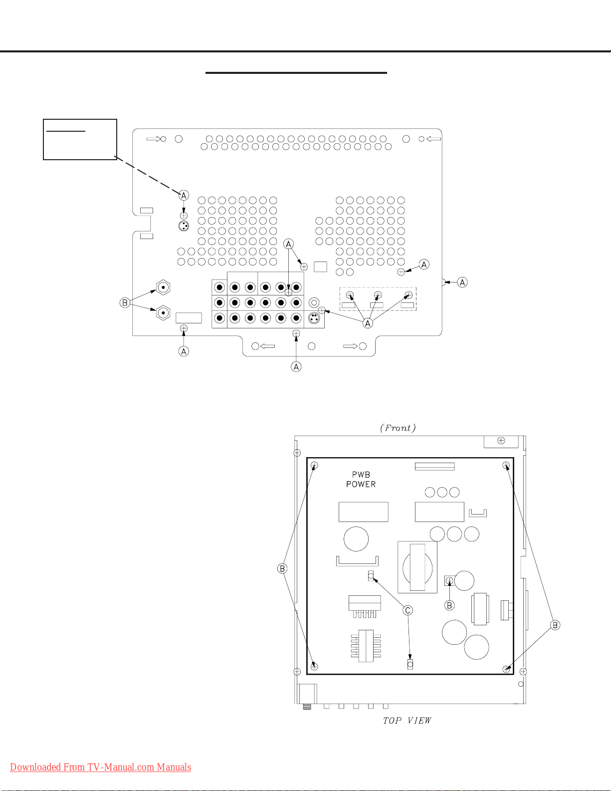
PWB-POWER Removal
1) Remove five screws (B)
2) Disconnect all cables to the PWBPOWER.
3 ) Release clips (C).
4 ) Carefully lift the PWB-POWER from the
chassis box.
PWB-POWER Installation
1 ) Reverse the removal procedure to install a
new PWB-POWER.
2 ) No data transfer is required.
Downloaded From TV-Manual.com Manuals
Page 8

MODELS: WD-60735 / WD-60C8 / WD-65735 / WD-65736 / WD-65835 / WD-65C8 / WD-73735 /
WD-73736 / WD-73835 / WD-73C8
Chassis Disassembly (continued)
Chassis Cover Removal
1 ) Remove 3 screws (C).
2 ) Lift the Chassis Cover from the chassis box.
PWB-HDMI-FRONT Removal
1) Disconnect all cables to PWBHDMI-FRONT
2 ) Remove three screws (D).
3 ) Carefully lift the PWB-HDMI-
FRONT from the chassis box.
4) T o remove PWB-HDMI, remove
two screws (E) and slide the PWB
out the rear of the shield.
Downloaded From TV-Manual.com Manuals
Page 9
MODELS: WD-60735 / WD-60C8 / WD-65735 / WD-65736 / WD-65835 / WD-65C8 / WD-73735 /
WD-73736 / WD-73835 / WD-73C8
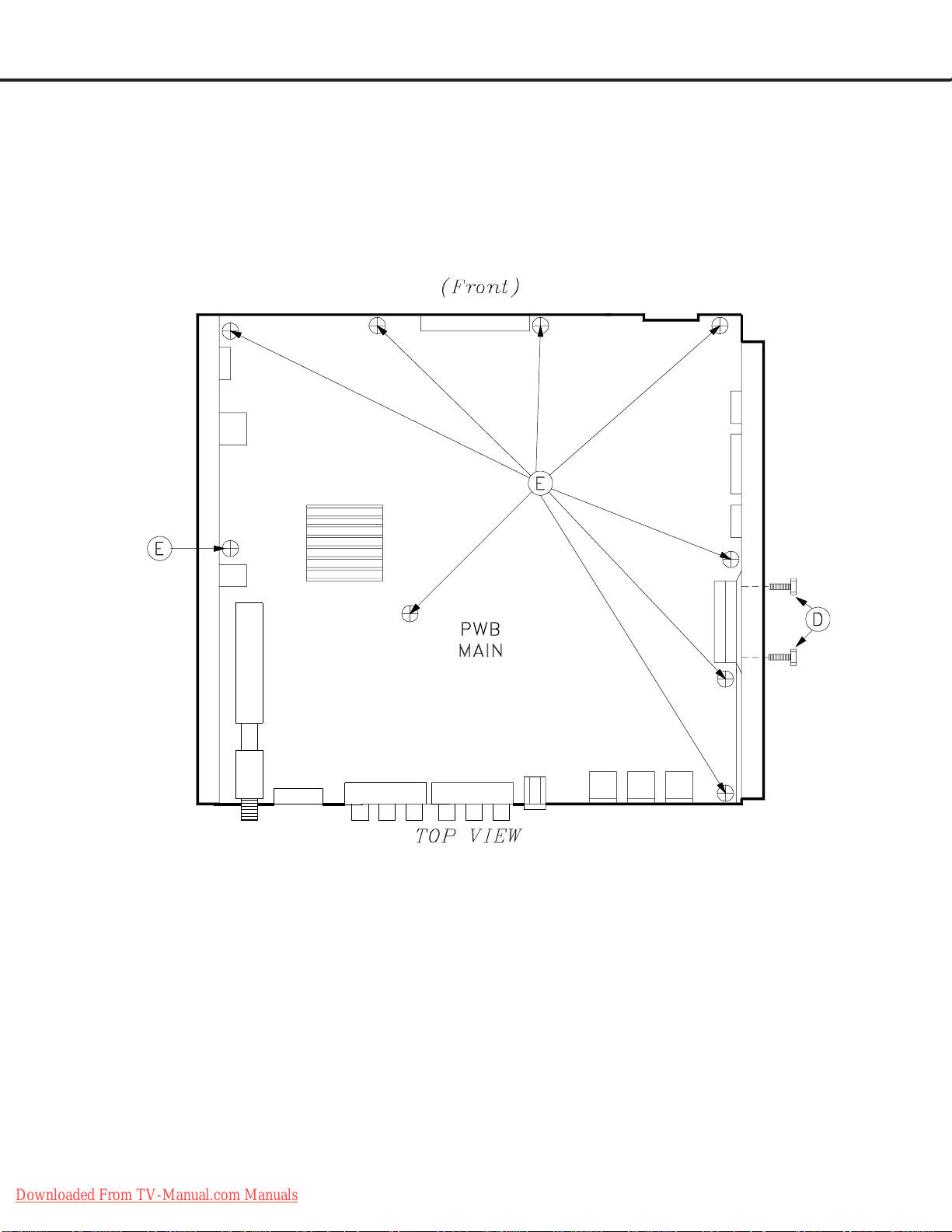
PWB-MAIN Removal
1 ) Disconnect all cables to PWB-MAIN
2 ) Remove two screws (D).
3 ) Remove screws (E).
4 ) Carefully lift the PWB-MAIN from the chassis
box.
PWB-MAIN Installation
1 ) Install two screws (D) first
2 ) Then install screws (E).
3) Transfer Index Data from Engine
(refer to page 32)
4 ) Restore Alignment and White Balance Settings.
5 ) Restore Keystone Geometry from Backup.
Downloaded From TV-Manual.com Manuals
Page 10

MODELS: WD-60735 / WD-60C8 / WD-65735 / WD-65736 / WD-65835 / WD-65C8 / WD-73735 /
WD-73736 / WD-73835 / WD-73C8
OPTICAL ENGINE REMOVAL
OPTICAL ENGINE ASSEMBLY REMOVAL
1 ) Remove 3 screws (C) from the Optical Engine.
2 ) Disconnect all cables to the Optical Engine Assembly.
3 ) Carefully slide the Optical Engine assembly from the cabinet.
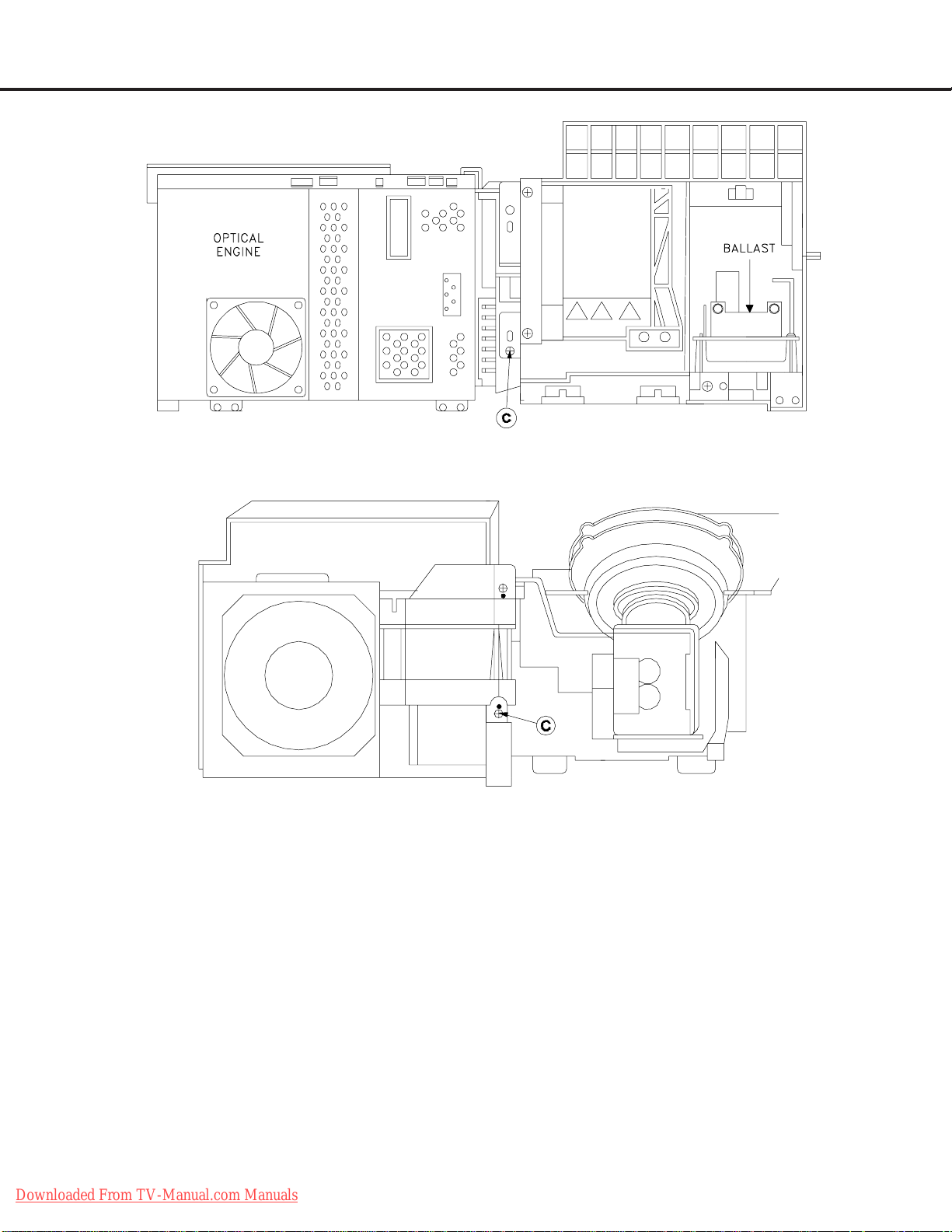
OPTICAL ENGINE ASSEMBLY AND CONNECTOR LOCATIONS
Downloaded From TV-Manual.com Manuals
(Rear View)
Page 11
MODELS: WD-60735 / WD-60C8 / WD-65735 / WD-65736 / WD-65835 / WD-65C8 / WD-73735 /
WD-73736 / WD-73835 / WD-73C8
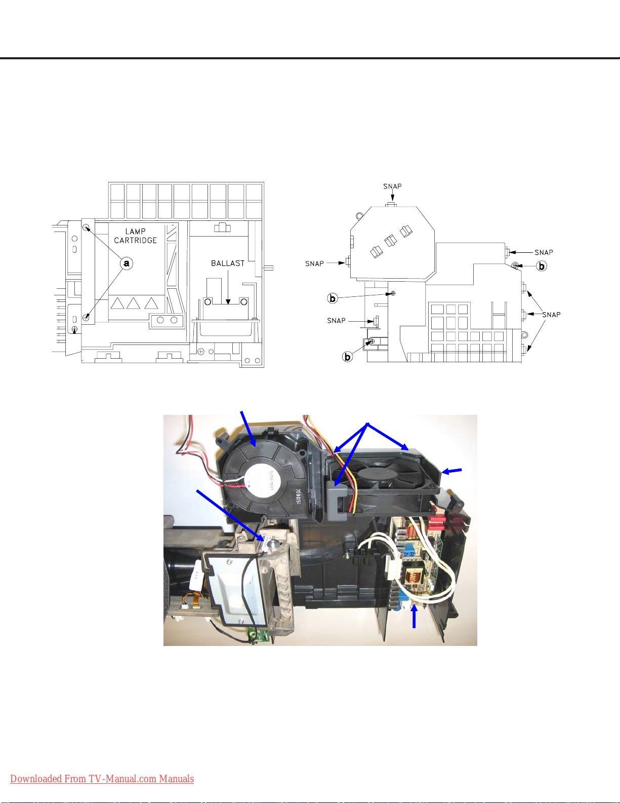
OPTICAL ENGINE REMOVAL FROM THE DUCT ASSEMBLY
Upper Duct Assembly Removal Procedure
1 ) Disconnect the Ballast Fan and Lamp Fan from the back of the Engine (connectors J4 and J8) and loosen
wiring harnesses from the looms, refer to page 1 1 for connector locations.
1 ) Loosen two screws (a) to remove the Lamp Cartridge, refer to Figure 1.
3 ) Remove 3 screws (b) from the top of the upper duct and release the 7 snaps shown in Figure 2.
4 ) Carefully remove the upper Duct assembly
Figure 1: Duct Assembly (Rear View)
Sirocco Fan
Thermal
Sensor
Figure 2: Duct Assembly (Top View)
Exhaust Fan
Hol ders (3)
Exhaust
Fan
Ballast
Figure 3: Lower Duct (Top View)
LOWER DUCT (Upper Duct Removed)
1) Figure 3 shows the components in the Lower Duct.
2 ) The Sirocco Fan and Exhaust Fan can be replaced. The Engine and Upper Duct do not have to be removed
to replace the Ballast.
3 ) If replacing the Engine, remove the Thermal Sensor from the Engine (1 screw) Figure 3.
Downloaded From TV-Manual.com Manuals
Page 12
MODELS: WD-60735 / WD-60C8 / WD-65735 / WD-65736 / WD-65835 / WD-65C8 / WD-73735 /
WD-73736 / WD-73835 / WD-73C8
Figure 4: Lower Duct r ear Mounting Screw
LOWER DUCT REMOVAL
1 ) Remove the 2 screws (C) one in front and one in the rear of the lower duct, refer to Figures 4 and 5.
2 ) Carefully remove the lower duct from the Engine.
ENGINE REPLACEMENT (Reverse the Removal Procedure)
1 ) Install Duct assembly on the new Engine.
2 ) Remove the Protective Lens Cover from the face of the Lens.
3 ) Install the Engine Assembly in the cabinet.
4 ) After a new Engine is installed Load Index Delay Data from the Engine and Copy Settings to
Backup (page 32).
5 ) Adjust Raster Centering (page 28) and Manual Keystone Geometry Alignment (page 29) if
needed.
Downloaded From TV-Manual.com Manuals
Figure 5: Lower Duct front Mounting Screw
Page 13

MODELS: WD-60735 / WD-60C8 / WD-65735 / WD-65736 / WD-65835 / WD-65C8 / WD-73735 /
WD-73736 / WD-73835 / WD-73C8
BALLAST ASSEMBLY REMOVAL
REMOVAL PROCEDURE
1 ) Remove screw (A) from the Ballast support
and screw (B) if the Engine is still mounted
in the cabinet.
2 ) Slide the Ballast Assembly out the rear of
the Engine assembly and unplug the Lamp
connector (C) at the Ballast.
3 ) Disconnect connectors CJ1 and CJ3.
4 ) Remove screw (D) to remove the PWB-
BALLAST from the Ballast Support.
Reverse the procedure to install a new
Ballast .
SCREEN REMOVAL & REPLACEMENT
WD-65835 & WD-73835 Only
Escutcheon Removal
Before Removing the Screen Assembly
(V39++ Models Only)
1 ) Remove 2 screws (A) at the lower rear corner on
the right side.
2 ) Remove the small escutcheoncover to access the
SB1 connector
3 ) Unplug the SB1 connector. This disconnects the
PWB-SBL-R & PWB-SBL-L.
Screen Assembly (Bezel) Removal
1 ) Remove all rear screws (B) except one in an upper corner (To support the
screen assembly while removing the front mounting screws).
60 Inch Models
Downloaded From TV-Manual.com Manuals
Page 14

MODELS: WD-60735 / WD-60C8 / WD-65735 / WD-65736 / WD-65835 / WD-65C8 / WD-73735 /
WD-73736 / WD-73835 / WD-73C8
SCREEN REPLACEMENT (continued)
65 inch Models
Downloaded From TV-Manual.com Manuals
73 inch Models
Page 15

MODELS: WD-60735 / WD-60C8 / WD-65735 / WD-65736 / WD-65835 / WD-65C8 / WD-73735 /
WD-73736 / WD-73835 / WD-73C8
SCREEN REPLACEMENT (continued)
Screen Assembly Removal
(continued)
2 ) Open the Control Panel door and remove two screws (A).
3 ) Remove the remaining rear screw in the upper corner and carefully pull the screen assembly
from the cabinet.
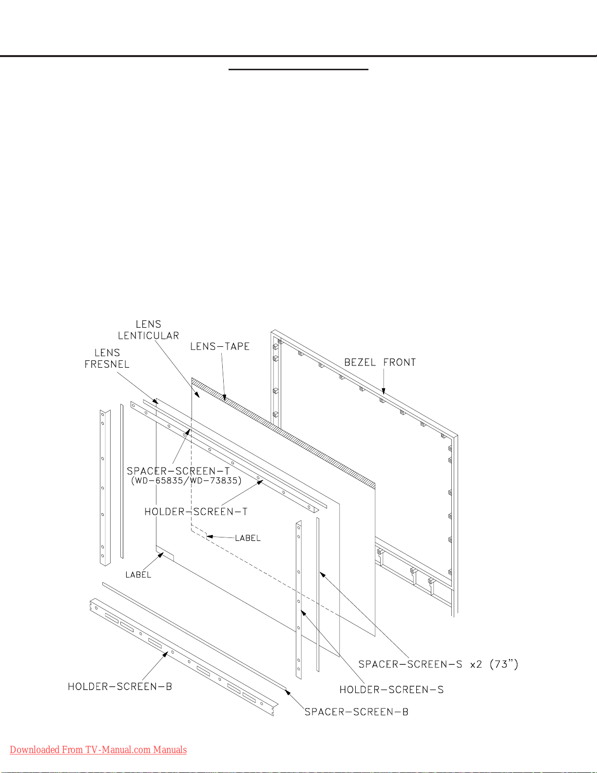
Screen Removal From the BEZEL-FRONT
1 ) Remove the screws (A) from the top, bottom and side rails.
2 ) Lift the Fresnel Lens and Lenticular screen from the BEZEL-FRONT.
Downloaded From TV-Manual.com Manuals
Page 16

MODELS: WD-60735 / WD-60C8 / WD-65735 / WD-65736 / WD-65835 / WD-65C8 / WD-73735 /
WD-73736 / WD-73835 / WD-73C8
SCREEN REPLACEMENT (continued)
Downloaded From TV-Manual.com Manuals
Page 17
MODELS: WD-60735 / WD-60C8 / WD-65735 / WD-65736 / WD-65835 / WD-65C8 / WD-73735 /
WD-73736 / WD-73835 / WD-73C8
Screen Replacement
CAUTION: Wear gloves when handling the Lenticular Screen and Fresnel Lens.
This prevents cuts and finger prints. Do not place Fresnel Lens in the sun.
This may cause fire and heat related injuries.
Lenticular Screen and Fresnel Lens Removal
1 ) Remove the top, bottom and side HOLDER-SCREEN rails and their cushions from the Bezel.
2 ) Lift the screens as a single unit from the frame.
2. Separate the Lenticular Screen and Fresnel Lens.
Note: When separating the Lenticular Screen from the Fresnel Lens, use caution
while prying the Screen and Lens apart. Use a slot type screw driver, and
remove the pressure sensitive double sided tape.
Lenticular Screen and Fresnel Lens Replacement
1 ) Apply LENS-TAPE along the rear top edge of the Lenticular Screen.
2 ) Place the Fresnel Lens on top of the Lenticular Screen, and apply pressure along the top edge.
3 ) Place the screens in the screen frame and reinstall the cushions, top, bottom and side rails.
NOTE: The Lenticular Screen label must face the front and the Fresnel Lens label face the rear.
4 ) Reverse the Screen Removal Procedure and insert the screens in the Bezel.
Downloaded From TV-Manual.com Manuals
Page 18
MODELS: WD-60735 / WD-60C8 / WD-65735 / WD-65736 / WD-65835 / WD-65C8 / WD-73735 /
WD-73736 / WD-73835 / WD-73C8
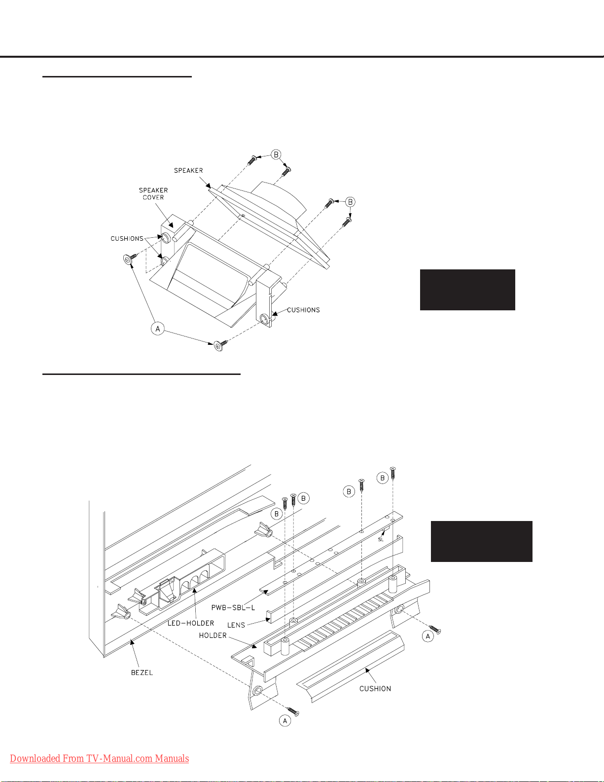
Speaker Replacement
1 ) Remove the Bezel screen assembly to access the speakers.
2 ) Remove 2 screws (A) and carefully slide the Speaker Assembly from the cabinet.
3 ) Disconnect the leads to the speaker.
4 ) Remove 4 screws (B) to remove the speaker from the speaker cover.
5 ) Reverse the procedure to install a replacement speaker.
SPEAKER
ASSEMBLY
WD-65835 & WD-73835 (Only)
PWB-SBL-R & PWB-SBL-L Replacement
1 ) The screen Bezel Assembly must be removed to access the PWBs-SBL (refer to the V38 Bezel Removal
Procedure).
2 ) Remove 2 screws (A) to remove the PWB-SBL assembly from the Bezel.
3 ) Remove 4 screws (B) to remove the PWB from the assembly.
4 ) Reverse the procedure to install a replacement PWB-SBL.
V39++ SBL
ASSEMBLY
Downloaded From TV-Manual.com Manuals
Page 19
MODELS: WD-60735 / WD-60C8 / WD-65735 / WD-65736 / WD-65835 / WD-65C8 / WD-73735 /
WD-73736 / WD-73835 / WD-73C8
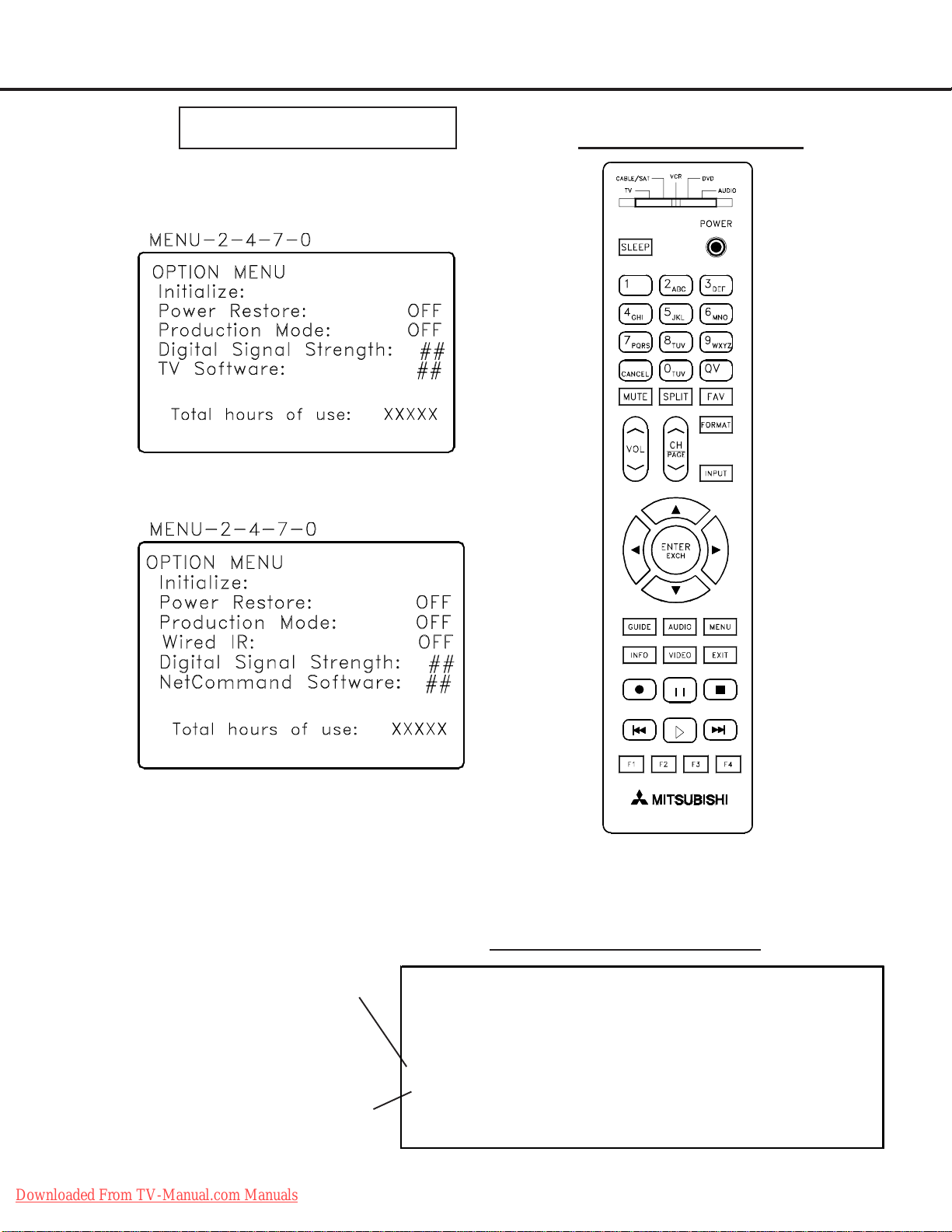
OPTION MENU
1. Press the “MENU” button on the remote hand unit.
2. Press the buttons “2”, “4”, “7” and “0” in order.
(The screen will change to the option menu.)
V39 OPTION MENU
REMOTE CONTROL
V39+ & V39++ OPTION MENU
Digital Signal Str ength
1. Tune to a Digital Channel
2. From the Option menu scroll down and highlight Digital Signal Strength
3. Press Enter
SNR Recommended Levels:
VSB = 15 to 35
64 QAM = 22 to 34
256 QAM = 27 to 37
Downloaded From TV-Manual.com Manuals
Signal Quality
Index (0-100)
Signal Noise
Ratio
Example of Digital Signal Strength Display
Tuner 0 Tuner 1 OOB Tuner
Frequency (MHz): 597 0 0
Signal Level: 8 0 0
Modulation: 256 QAM Unknow n Unknown
Car rie r Lock : Lo cked Unk nown Unkn o wn
SQI 100 0 0
SNR 34.3 0 0
Correctable errors: 0 0 0
UnCorrectabel erro rs: 0 0 0
Page 20

MODELS: WD-60735 / WD-60C8 / WD-65735 / WD-65736 / WD-65835 / WD-65C8 / WD-73735 /
)
)
)
)
)
)
g
g
y
WD-73736 / WD-73835 / WD-73C8
Reset / Initialization
SERVICE TIP:
Many customer generated symptoms, intermittent symptoms or no symptom found can be resolved by using the
various Reset and Initialization options. Before visiting the customer’s home ask the customer 1st to try the System
Reset button on the control panel and if this does not resolve the issue, then they can perform an A/V Reset by
pressing the Guide + Format buttons on the front panel at the same time. Then, if necessary , perform a user level
Initialization by pressing MENU-123-ENTER with the remote. The customer should be made aware when settings
and/or options will be reset. For more information, see the chart below.
NOTE: During Initialization, the set will reboot. Wait until the Power
LED stops flashing before unplugging or powering ON the TV .
Reset / Initialization Guide
Reset Name When to use How to us e Resulting Acti on
Remote
Contro l TV
Layer Reset
Remote
Contro l TV
Volume/Mute
functions
A/V Memory
Reset , by
individual input
Returns the remote control TV
layer to normal operation.
Returns the volume and mute
functions of the remote control to
TV volume and mute for TV,
Cable/Sat, VCR and DV D layers
after the Audio Lock for AV
Receiver featur e has been used.
When the audio and or video
settings f or a sing le input seems to
be inco rrect.
1
Set the sl id e switch to TV
2)
pos ition.
2
Press and hold the
3
twice then rel ease the button.
3)
Enter the code
1
(1) Set the slid e switch to TV positi on.
2
(2) Press and hol d the POWER button until it
2
flashes twice then release the button.
3)
(3) En ter th e code
MENU --> Audio/Vi deo--> AV Reset
POWER
0 0 9 3 5
9 9 3 VOL UP
button until it flashes
.
.
Once the valid code has
b een enter ed and
confirmed, the temot
contrrol has been reset.
The remote will now
operate the TV's volume
and mute when the slide
switch is in the TV,
C ABLE /SAT , VCR or
DVD positio ns.
All Audio a nd Vid eo
settings for the individual
input are reset except for
Listen To, Language,
the
Balance
Caption
Closed
and
settings.
A/V Reset, all
inputs
System Res et To reset the TV when it does not
Initialize User
Level
Initialize S erv ice Leve l
V-Chip
Password
Bypass
Unlock Fron t
Panel
To reset audio and video
adju stments for all inpu ts to the
original factor y settings.
turn on or off, does not respond to
the remote control, front panel
buttons or has other unusual
symptoms.
To reset all cu st om er setti ngs
except V-Chi p
To reset all cu st om er setti ngs All custo me r menu
If V-Chip password is not known Password will be
To unlock the front p anel if it has
been locked in the V-Chip Menu.
While view ing the T V, press the front panel buttons
GUIDE + FORMAT at the same ti me.
Pr ess th e SYSTEM RESET button o n the front panel
with a pointe d object such as a p encil or paperclip.
Press MENU - 123 - ENTER
MENU - 2470. Highlight INITIALIZE and press ENTER
Press QV + 9 at t he sa me tim e.
Press and hold the front panel MENU button for 8
seconds.
All Audio a nd Vid eo
settings are reset to the
facto ry defa ult settings.
No other menu options
are changed.
TV Micro Re-boots. Note:
The c han
the current TV -On period
may be lost. All o t her
pr ev i ous us e r sett i n
not lost.
All customer menu
options and A/V settings
excep t V-Chip are reset to
facto ry defa ult.
options and A/V settings
are reset to factory
default.
b
passed. If in the V-Chip
menu, enter a new
password.
Front Pane l becomes
operational. Other V-Chip
sett in gs not changed.
Note: Cannot be
pe rformed while in the
Lo w Power mode and the
set is Off.
es made during
s are
Downloaded From TV-Manual.com Manuals
Page 21
MODELS: WD-60735 / WD-60C8 / WD-65735 / WD-65736 / WD-65835 / WD-65C8 / WD-73735 /
WD-73736 / WD-73835 / WD-73C8
INITIAL SETTINGS
Audi o/Video Setup Menu (continued)
Settings
Video Ant2 Air --
P ictu re M ode Bri lliant Ant2 Cable -Brilliant C ontra st 1 00% Edit
Brilliant Brightness 50% Channel in Memory All
Color 50% Name -Tint 50% FAV1 ~ FAV6 unchecked
Sharpness 50% Lock Unlock
Brillian t Color Temp. High Clock
Deep Field Imager (V39++) On Settings Manual
Video Noise (O ff -Low-Mid-High) Time 12:00PM
Audio (A/V Receiver) Date 1/01/2007
Speakers 50% Time Zone Eastern
Bass 50% Daylight Savings Applies
Treble 50% Timer
Balance Off Timer Off
Surround Stereo Day Dail y
L isten T o ( Ana log only) Engli sh Tim e 12 :0 0PM
Language (Digi tal only) Off Device ANT-1
Level Sound Channel 2
PerfectColor On Energy Mode Fast power on
PerfectColor On Lamp Mode Standard
PerfecTint Other Ratings Gray out
Global Medium O ther ratings Off
Video Mu t e On
Film Mode Auto Name
SharpEdge (V39++) On Ant-1 On
Lamp Mode Standard Ant-2 On
Blue Glow (V39++ only) On if TV On Input-1 Gray out
FX Gaming Gray out Input-2 Gray out
Game Mode Off Input-3 (Front) Gray out
Glasses L-R Standard Comp-1 Gray out
Capt ions Menu Comp-2 Gray out
Closed Captions
Analog C aptions On if Mute HDM I-1 Gray out
Backgro und Gray HDMI-2 Gra y out
Digital Captions On if Mute HDMI-3 Gray out
Digi tal Settings HDMI-4 (Front) Gray out
Font Default (Only V39+/V39+ +)
Font Si ze Large Learn (Only V39+/V39++)
Font Color White A/V Receiver
Font Opacity Translucent (Only V39+/V39++)
Background Color Black Learn Gray until auto sensing
Background Opacity Transluc ent Learn/Name --
Setup Menu
Language English Assign Input 2 Gray out
Scan Assign Input 3 Gray out
Ant1 Air -- Assign Input 4 Gray out
Ant1 Cab le --
Inputs Menu
Co mp -3 (Front) Gr ay out
Assign Input 1 Gray out
Standard
Downloaded From TV-Manual.com Manuals
(Continued on Page 23)
Page 22
 Loading...