

Page 1

DLP
TM
Projector
VS-SH10U
Set-up and Installation Manual
August 30, 2002
Page 2

First edition
2
Table of Contents
1. PRODUCT DESCRIPTION............................................................................................................5
1.1. Specifications..........................................................................................................................5
1.1.1. Image Panel.....................................................................................................................5
1.1.2. Electric Specification........................................................................................................5
1.1.3. Optical Specification........................................................................................................6
1.1.4. Mechanical Specification.................................................................................................6
1.1.5. Reliability and Serviceability ............................................................................................6
1.1.6. Environmental condition ..................................................................................................7
1.1.7. Safety Approval................................................................................................................7
1.1.8. Options.............................................................................................................................7
1.2. Outline drawings .....................................................................................................................8
1.2.1. Circuit Box........................................................................................................................8
1.2.2. Optical Unit ......................................................................................................................9
1.3. Control Panel.........................................................................................................................10
1.3.1. Outline view ...................................................................................................................10
1.3.2. RS-232C terminal ..........................................................................................................11
1.3.3. Control terminal..............................................................................................................11
1.3.4. Digital input terminal ......................................................................................................11
1.4. Dip switch setting ......................................................................................................... .........12
1.5. Buttons and functions of remote control unit ........................................................................13
1.6. LED display...........................................................................................................................14
2. ADJUSTMENT MENU .................................................................................................................15
2.1. Remote controllable items ....................................................................................................15
2.2. Projector information display.................................................................................................15
2.3. Video memory select.............................................................................................................15
2.4. Picture mute..........................................................................................................................15
2.5. Test pattern display ...............................................................................................................16
2.6. RGB color mute.....................................................................................................................16
2.7. Remote ID function ...............................................................................................................16
2.8. Picture adjustment menu ......................................................................................................17
2.9. Service menu ........................................................................................................................20
2.10. Factory menu.....................................................................................................................25
3. SET-UP A ND INSTA LLATION.....................................................................................................29
3.1. Set-up & installation flow chart..............................................................................................29
3.2. Picture outline adjustment.....................................................................................................30
3.2.1. Displaying internal test signal for picture outline adjustment........................................30
3.2.2. Adjusting 6 axes.............................................................................................................31
3.2.3. Picture outline adjustment steps....................................................................................32
3.2.4. For delivery ....................................................................................................................33
3.3. Dip switch setting ......................................................................................................... .........33
3.4. Multiple screen color space control (CSC) adjustment.........................................................33
Page 3

VS-SH10U Set-up and Installation Manual
3
3.4.1. Black level adjustment...................................................................................................33
3.4.2. CSC adjustment.............................................................................................................33
3.4.3. White balance adjustment.............................................................................................35
3.4.4. Gradation adjustment.....................................................................................................35
3.5. Video signal adjustment........................................................................................................36
3.5.1. Memory select................................................................................................................36
3.5.2. MENU2 adjustment (Only when analog is input)...........................................................36
3.5.3. MENU1 adjustment (effective for both analog and digital input)...................................39
4. AUTO LAMP CHANGER.............................................................................................................40
4.1. Overview of lamp changer ....................................................................................................40
4.2. Caution..................................................................................................................................40
4.3. Sp are lamp cartridge replacing/adjusting procedure............................................................41
4.3.1. Record new lamp data...................................................................................................41
4.3.2. The lamp to replace confirmation..................................................................................41
4.3.3. Lid detaching..................................................................................................................41
4.3.4. Lamp pulling out.............................................................................................................41
4.3.5. New lamp inserting ........................................................................................................41
4.3.6. Lid attaching...................................................................................................................41
4.3.7. Lamp timer confirmation ................................................................................................42
4.3.8. CSC calculating .............................................................................................................42
4.3.9. Lamp exchanging...........................................................................................................42
4.3.10. CSC manual adjustment............................................................................................42
4.3.11. Gradation adjustment.................................................................................................42
4.3.12. Lamp exchanging.......................................................................................................42
4.3.13. Error code erasing......................................................................................................42
4.4. Auto lamp change action ......................................................................................................42
4.4.1. At lamp burn-out ............................................................................................................42
4.4.2. At lamp brown-out..........................................................................................................43
4.5. Manual lamp change action..................................................................................................43
4.5.1. At lamp lighting..............................................................................................................43
4.5.2. At stand-by mode...........................................................................................................43
4.6. Information display................................................................................................................44
4.6.1. Warning message..........................................................................................................44
4.6.2. Operation time and error indication...............................................................................44
4.7. Lamp exchanging time..........................................................................................................44
5. COMMUNICA TION PROTOCOL.................................................................................................45
5.1. Communication rules ............................................................................................................45
5.2. Command character strings..................................................................................................45
5.3. Command ID.........................................................................................................................45
5.4. Sequence..............................................................................................................................45
5.5. Command return value..........................................................................................................46
5.6. Control commands................................................................................................................47
5.6.1. vP (Power) .....................................................................................................................47
Page 4

First edition
4
5.6.2. NP (Picture Mute) ..........................................................................................................48
5.6.3. i (Input Select)................................................................................................................48
5.6.4. iE (Input Port Save)........................................................................................................48
5.6.5. n (Memory Select)..........................................................................................................49
5.6.6. nE (Memory Save).........................................................................................................49
5.6.7. nA (Analog Input, Memory Select).................................................................................49
5.6.8. nD (Digital Input, Memory Select)..................................................................................49
5.6.9. vS (System Status) ........................................................................................................50
5.6.10. e (Error Detection)......................................................................................................51
5.6.11. ISA (Lamp-A Status)...................................................................................................51
5.6.12. ISB (Lamp-B Status) ..................................................................................................51
5.6.13. ST1 (Status Information)............................................................................................52
5.6.14. ST2 (Lamp Timer Value)............................................................................................52
5.6.15. ST3 (Set Timer Value)................................................................................................53
5.6.16. STR1 (Lamp Timer Reset).........................................................................................53
5.6.17. STR2 (Mt Bit Reset)...................................................................................................53
5.6.18. MT (Maintenance request information)......................................................................54
6. STANDARD INSTALLATION CONFIGURA TION.......................................................................55
6.1. Optical unit ............................................................................................................................55
6.2. 6-axis adjuster.......................................................................................................................56
7. ABOUT TRADEMARKS..............................................................................................................57
8. REVISION A RCHIV E...................................................................................................................58
Page 5
VS-SH10U Set-up and Installation Manual
5
1. Product description
1.1. Specifications
1.1.1. Image Panel
Type DLP
TM
(0.9” DMDTM 1 chip)
Resolution 1,280x1,024 pixels
1.1.2. Electric Specification
Signal input terminal
Analog RGB: 5BNC (RGBHV) x1
Digital RGB: MDR 20 pins x1
Horizontal
59.7k – 64.3kHz
Sync width: > 0.5 µS
BP width: > 50 clocks
No interlace signals
Input scanning
frequency
Vertical
56 – 61Hz
Sync width: > 2lines
Sync width + BP width: > 29lines
Pixel clock rate 91M – 115MHz
Analog RGB video
input
Signal
Video: 0.7V
P-P
+/- 5% positive / 75 ohm
Synchronous: TTL level (positive/negative)
High level:2.5 – 5.0V
Low level : 0 – 0.5V
Sync on green: Video: 0. 7V
P-P
+/- 5% positive
Synchronous: 0.3V
P-P
+/- 5% negative
Digital RGB vide o
input
Signal TMDS (DFP Pin assignment)
RS-232C: D-Su b 9 pi ns
RS-422: D-Sub 9 pins x2 (input, out put )
Wire remote: F3.5 Jack
Control signal input
IR receiver
Set up switch 8 bits x 2
Gray scale resolution 8 bits (10 bits after dit her)
Function Color S pace Control/ Digital Gradation / Digita l Gamma
Light source
Ultra-high pressure mercury lamp 120W
(average lifetime 4,000 hours)
Voltage range AC 100 – 240V +/-10% , 50/60Hz + / -5%
Power consumption (100/2 40V) 220/220 W
Operating current (100/240V) 3.0/1.5 Amp.
Inrush current (100/240V) 20/40 A m p.
Page 6
First edition
6
1.1.3. Optical Specification
Light output 480 ANSI Lumens (typ.)
Brightness uniformity 80% at 90% image height (typ. )
Contrast ratio (full field) 300:1 (typ.)
Magnification tolera nce 2%
Lateral color shift
Red(610nm) – Green(546.1n m)
Blue(470nm) – Green(546.1nm)
0.5pixel
Geometry distortion 0.3%
Image size 67” to 72” Diagonal image size
Throw ratio 0.74:1 nominal
Throwing distance
67”: 1000.2 +/-21.1 mm
70”: 1047.4 +/-22.0 mm
72”: 1078.9 +/-22.7 mm
1.1.4. Mechanical Specification
Optical Unit Circuit Box
Width 500mm 150mm
Height 300mm 300mm
Dimensions
Depth 300mm 200mm
Weight 10kg 6Kg
Packing dimensions 600(W) x 400(H) x 500(D) (mm)
Packing weight 25kg
Audio noise 50db
Supplied accessories
2 power cords
Cube connection control ca bles
User’s manual
1.1.5. Reliability and Serviceability
M.T.B.F
(exclude lamp, color wheel a nd fans)
20,000 hours
DMDTM chip expected life time 100,000 hours
Color wheel 30,000 h ours
Fans 30,000 hours
M.T.T.R Less than 60 min.
Page 7
VS-SH10U Set-up and Installation Manual
7
1.1.6. Environmental condition
Temperature and humidity
condition at operation
10°C – 40°C, 30% – 80% non cond ensing
Temperature and humidity
condition at storage
-20°C – 50°C, 20% – 80% non condensing
1.1.7. Safety Approval
Safety approval UL1950, CSA22.2 No. 950, EN60950
EMC
FCC part15 Class A
Industry Canada Class A
EN55022 Class A, EN55024, EN61000-3-2
EN61000-3-3
1.1.8. Options
6-axis adjuster S-050AXI
Remote controller R-FD10TX
Spare lamp unit S-SH10A / S-SH10B
Page 8
First edition
8
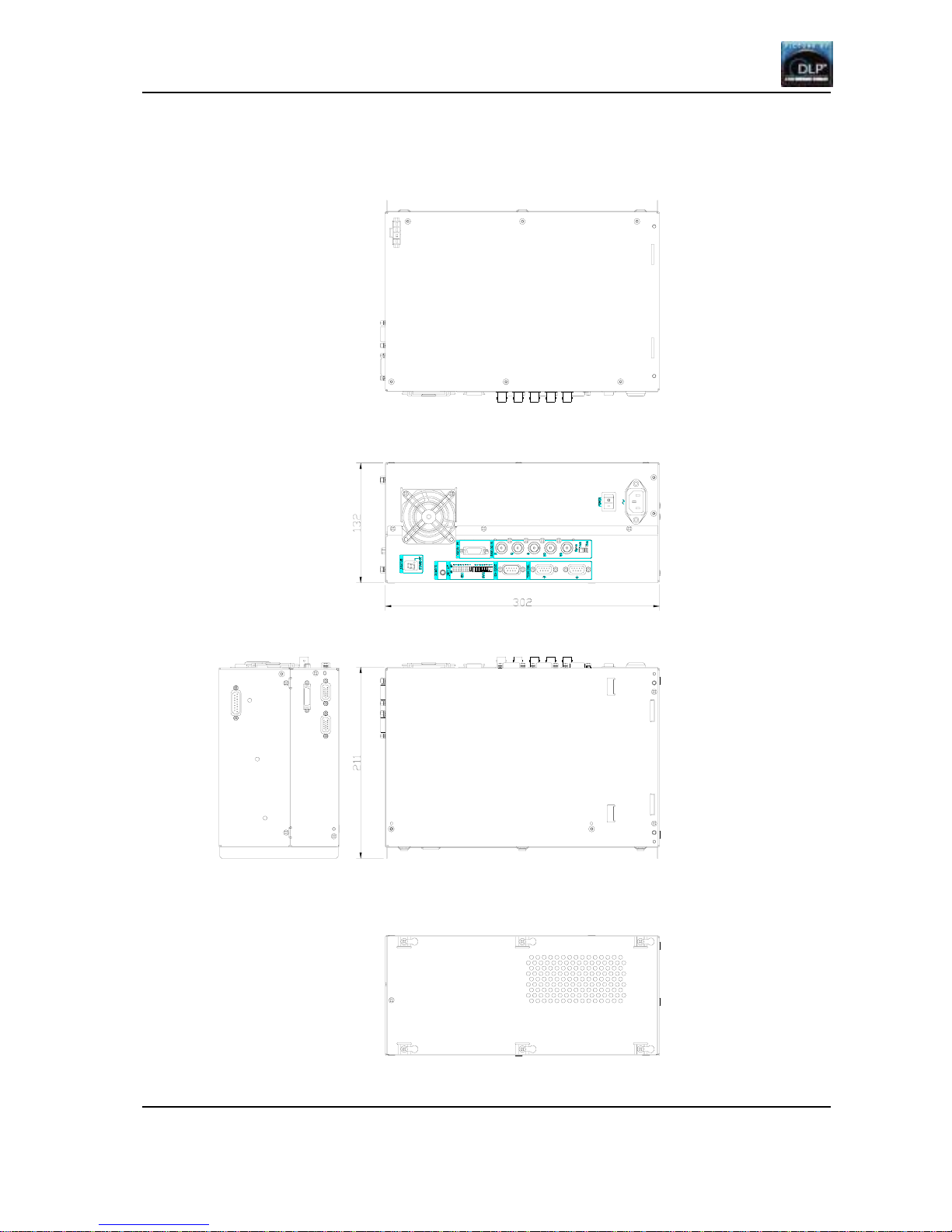
1.2. Outline drawings
1.2.1. Circuit Box
(unit: mm)
Page 9
VS-SH10U Set-up and Installation Manual
9
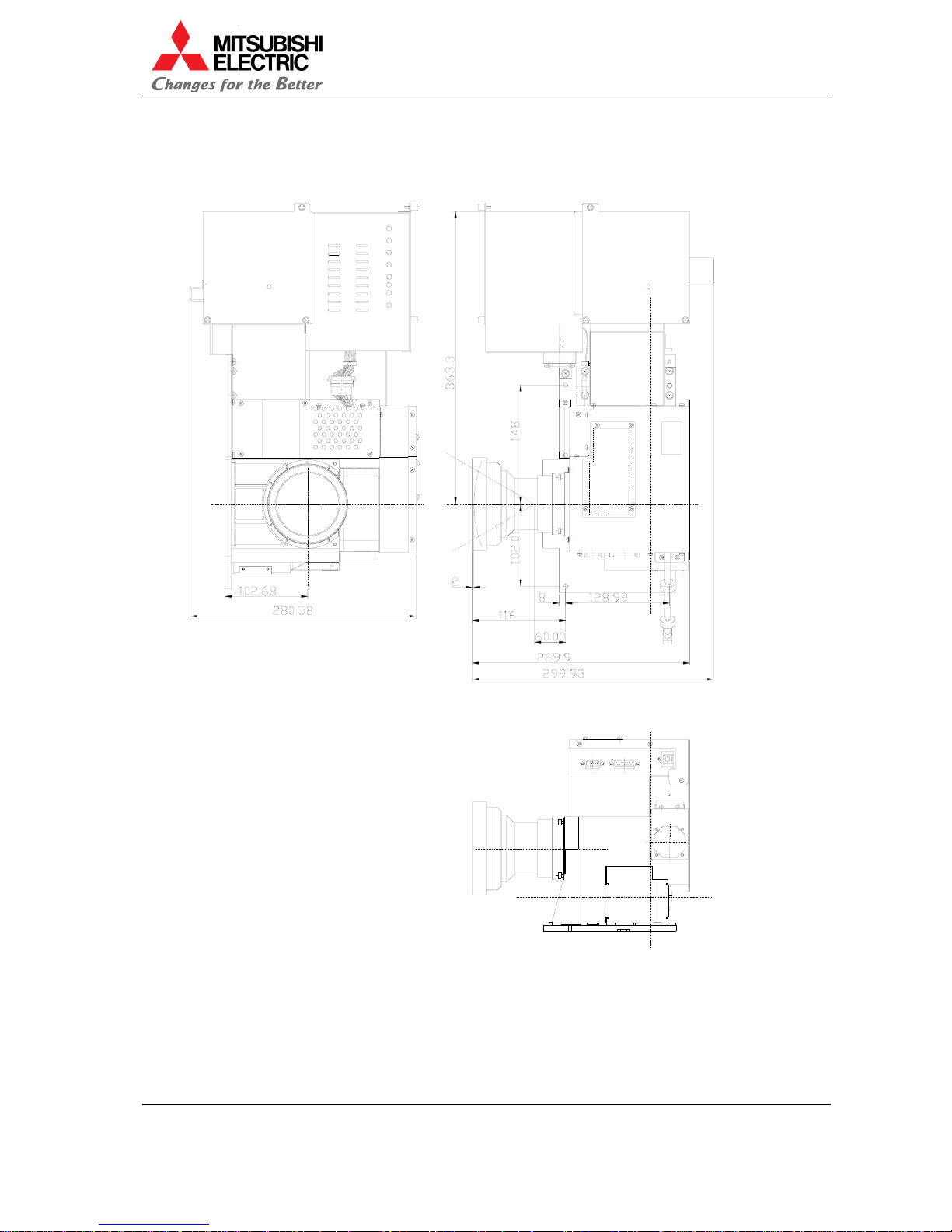
1.2.2. Optical Unit
(unit: mm)
Page 10

First edition
10
1.3. Control Panel
1.3.1. Outline view
1. Main power switch
2. AC socket
3. St at us LED display
4. Wired remote control in (3.5 mini jack)
5. Setup switch
6. RS-232C (D-SUB 9PIN(M))
7. Control IN (D-SUB 9PIN(F))
8. Control OUT (D-SUB 9PIN(F))
9. Digital IN ( M DR 20pin)
10. Analog IN (BNC X5)
1 1. Sync 75 ohm/1k ohm switch
Page 11
VS-SH10U Set-up and Installation Manual
11
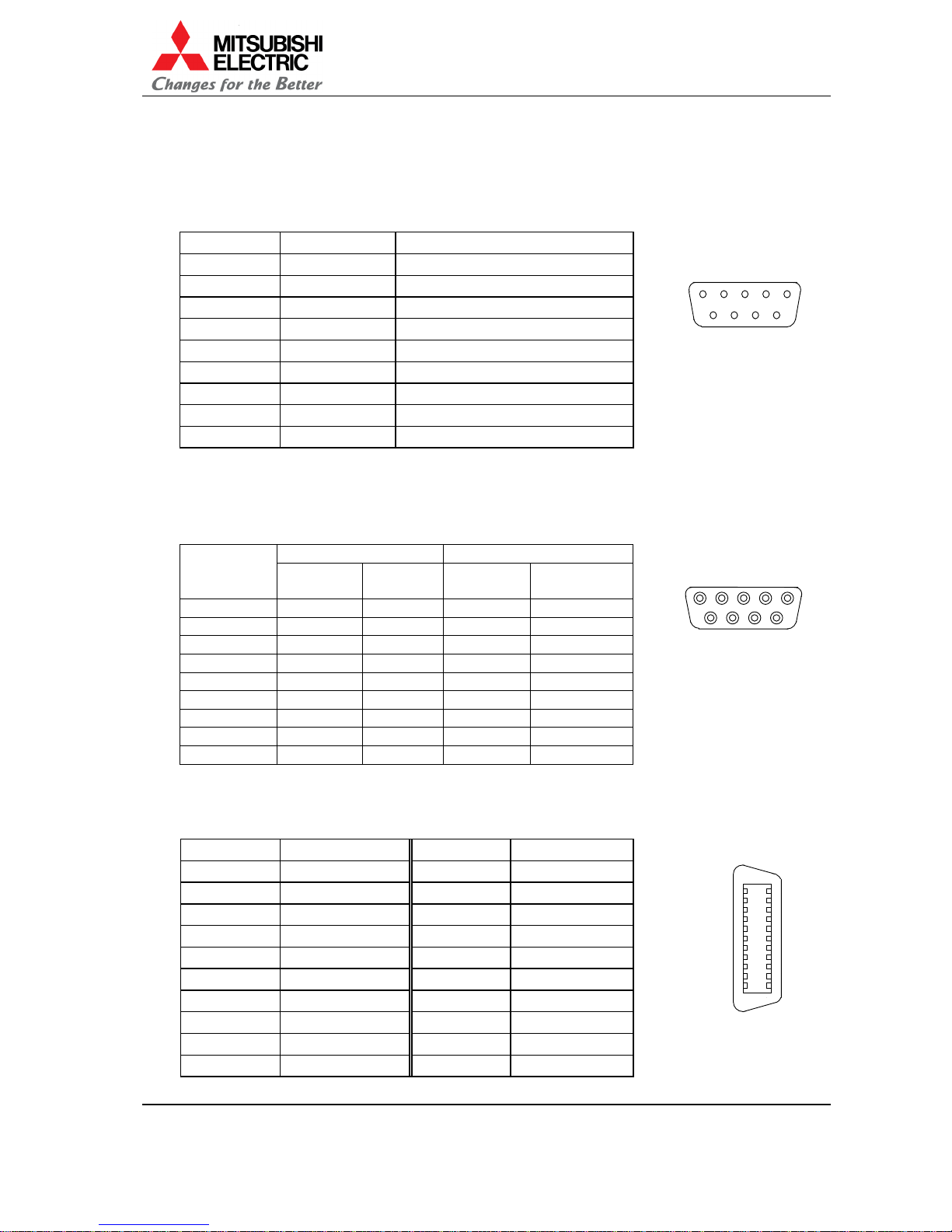
1.3.2. RS-232C terminal
Terminal: D-sub 9pi ns (male)
Crossing cable should be used to connect with PC.
Pin assignment:
Pin number I/O Signal
1 – N.C.(No Connection)
2 input RD (Receive Data)
3 output SD (Send Data)
4 output ER (Equipment Ready)
5 – SG (Signal Ground)
6 input DR (Data Set Ready)
7 – N.C.(No Connection)
8 – N.C.(No Connection)
9 – N.C.(No Connection)
1.3.3. Control terminal
Terminal: D-sub 9pins (fema l e)
Straight cab le (male – male) should be used to connect.
Pin assignment:
I/O Signal
Pin number
IN
terminal
OUT
terminalINterminal
OUT
terminal
1 input output RXB TXB
2 input output RXA TXA
3 N.C. N.C.
4 output input TXB RXB
5 output input TXA RXA
6 N.C. N.C.
7 N.C. N.C.
8GNDGND
9 input output RCIN RCOUT
1.3.4. Digital input terminal
Connect to the DIGIT A L IN terminal using the DFP cable.
Pin assignment:
Pin number Signal Pin number Signal
1 RXO - 11 RXC 2 RXO + 12 RXC +
3 RXO Shield 13 RXC Shield
4 RX2 Shield 14 RX1 Shield
5 RX2 - 15 RX1 6 RX2 + 16 RX1 +
7 DDCSCL 17 NC
8 DDCSDA 18 SENS
9 NC 19 DDC +5V
10 NC 20 DDC GND
8 97
6
53 41 2
7 689
13 25 4
10
1
20
11
MDR20
Page 12

First edition
12
1.4. Dip switch setting
SW-1
No. Name ON OFF
8 RC Remote cont rol enable Rem ot e cont rol disable
7 W-PROTECT F/W writable F/W not rewritable
6 B-RATE 19,200bps 9,600bps
5 RESERVED Reserved Default
4 RESERVED Reserved Default
3 RESERVED Reserved Default
2 RESERVED Reserved Default
1 FACTORY Factory set t ing mo de Stan dard
SW-2
No. Name ON OFF
8ID5
7ID4
6ID3
5ID2
4ID1
Designating unit ID (1 to 32) (ON: 0 OFF:1)
ID No. = 1x(ID1)+2x(ID2)+4x(ID3)+8x(ID4)+16x(ID5)
Example: ID No.=01: ID1= OFF, ID2 to ID5= ON
ID No.=32: ID1 to ID5= ON
3 422TERM1 T erminated Not terminated
2 422TERM2 T erminated Not terminated
1 RS232C RS 422 enable RS232C enable
SW-1
OFF
W-PROTECT
B-RATE
RESERVED
RESERVED
RC
RESERVED
FACTORY
RESERVED
8
ON
7
6
5
4
3
2
1
SW-2
ID4
ID3
ID2
ID1
422TERM2
ID5
422TERM1
RS232C
OFF ON
8
7
6
5
4
3
2
1
Page 13

VS-SH10U Set-up and Installation Manual
13
1.5. Buttons and functions of remote control unit
MITSUBISHI
R
G
MEM LIST
MENU1MENU2
FUNC
TEST
A
BY/C
1 2 543
6 7 098
Wired Remote Control Terminal
Connect REMOCON jack here
for wired control.
Remote Control Transmitte
r
Direct this side to the set.
Illumination Button
Press to turn ON/OFF the light o
f
the remote control unit. If the
remote control unit is not
operated for a certain period of
time, the illumination will
automatically be off.
Display Button
Press to display F/W version
information, etc.
MENU1 Button
Press to display adjustment menu1.
MENU2 Button
Press to display adjustment menu2.
Test Button
Press to display test patterns.
Press once for adjustment white.
Press twice for crosshatch.
Press 3 times for blue 180.
Press 4 times for gray 30.
Press 5 times for full-bit white.
Normal Button
Press to reset the adjusted data, etc.
Power Button
Press to turn ON/OFF the main
power.
PIC MUTE Button
Press to turn ON/OFF the picture
mute.
R/G/B Button
Press to select the color for
adjustment and to turn ON/OFF
the monochrome picture mute.
FUNC Button
Press for expanded functions.
ESC Button
Press to return to the prior
display during the menu mode.
Enter Button
Press to select and enter the item
during the menu mode.
UP/DOWN/RIGHT/LEFT Button
Press to move on the adjustment
menu and to change the
ad
j
ustment values.
Input Button
Press to select input signal.
A: Digital
B: N/A
VIDEO: Analog
Y/C: N/A
MEM LIST Button
Press to select the adjustment
memory.
Number Buttons
Press to select the adjustment
memory and to set remote ID, etc.
Page 14
First edition
14
1.6. LED display
LED display indicates the failure detection result such as shown in t he f ol low ing table.
LED display Failure detection
0 Fan stop
1 Lamp changer mechanical failure or no workable lamp
2 DMD control circuit failure
3 DMD control circuit failure
4 Lamp changer cont rol circuit failure
5 Internal SRAM f ai lure
6 (not defin ed)
7 Power failure
n No error
Projector state display
LED display Projector state
- (Bar at center) No signal
. (Dot) Stan d-by state
. (Blinking dot) During shutdown of the proj ect or
1, 2, 3, 4, 5 During startup of the projector
E While the flash memory is deleted
Displayed While the adjustment memory is updated, etc.
P While the value is written in the flash memory
Page 15
VS-SH10U Set-up and Installation Manual
15
2. Adjustment menu
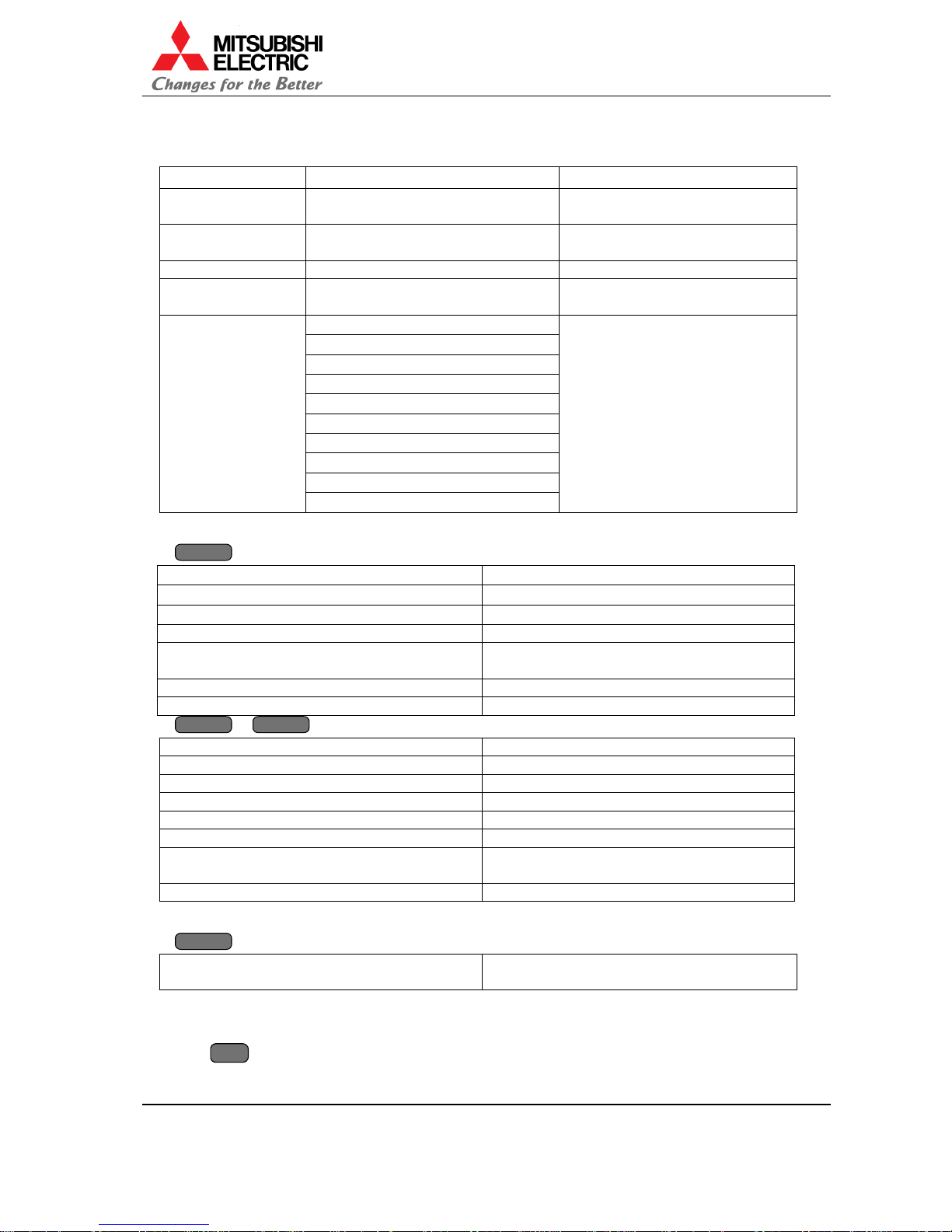
2.1. Remote controllable items
Mode Controllable item Memo
Boot mode invalid State that firmware is not written.
Remote control is not av ailable.
Stan d-by mode Turning on Power-off state. Only turning on
is available by remote control.
Start-up process T urning off
Shut down process invalid Remote cont rol is not available
for 30 seconds after shut down.
Turning off
Projector information display
Video memory select
Picture mute
Test pattern display
RGB color mute
Remote ID setting
Picture adjustment
Service adjustment
Steady state
Factory adjustment
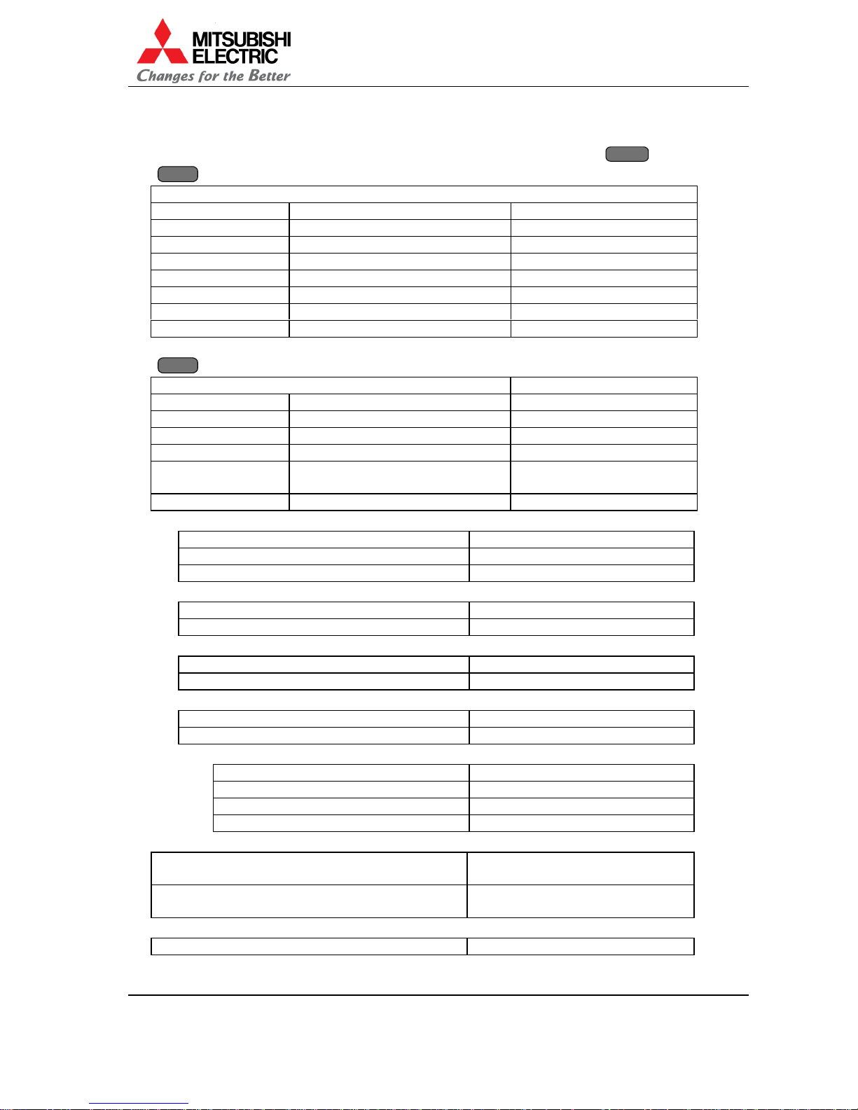
2.2. Projector information display
DISPLAY
DISPLAYDISPLAY
DISPLAY
button
LAMP TIMER 99999H La mp o perat i ng t i me
LAMP A BUSY NEW Lamp A status
LAMP B STANDBY NEW Lamp B status
INPUT ANALOG/DIGITAL Input select
SYSTEM ID 1 – 32 Remote ID setting. Red indications when
remote ID is disable.
NO SIGNAL (ANALOG) Indicating when no signal inputs.
MUTE Indicating on picture mute.
DISPLAY
DISPLAYDISPLAY
DISPLAY
+
FUNC
FUNCFUNC
FUNC
button
F/W VER H.18 Firmware version
H/W VER 1.1 Hardware version
SET TIMER 999999H Projector operating time
LAMP A TIMER 999999H Lamp A operating time
LAMP B TIMER 999999H Lamp B operating time
BAUD 19200/9600 Bau d rat e sel ect ion
F/W WRITABLE/
NOT WRITABLE
Firmware protection
MENU SW ON To be invisible certain items in factory menu.
2.3. Video memory select
MEM LIST
MEM LISTMEM LIST
MEM LIST
MEM LIST button (at non menu d isp lay)
MEMORY SELECT 1 Select 01 – 16 in number butt ons during 5-
second display.
2.4. Picture mute
Picture mute/ cancel
MUTE
MUTEMUTE
MUTE
Page 16

First edition
16
2.5. Test pattern display
Test pattern display/ cancel
TEST
Press once for adjustment white.
Press twice for crosshatch.
Press 3 times for blue 180.
Press 4 times for gray 30.
Press 5 times for full-bit white.
Test pattern display is also cancelled by pushing ESC button. If system is in the mode that you
can enter service menu by ESC but t on, service menu takes precedence over test p at tern
cancellation.
2.6. RGB color mute
Red color mute/ cancel
R
Green color mute/ cancel
G
Blue color mute/ cancel
B
2.7. Remote ID function
Use the remote ID to operate the remote co nt rol t ow ard specific projectors in the system.
Displaying remote control operability
Press
DISPLAY
button
Press
FUNC
+
DISPLAY
button
Setting to enable
Press
FUNC
+ 0 + 0 enables remote control towards all projectors (default setting in turning
on).
Press
FUNC
+ * + * (* stands for number button from 0 to 9) enables remote control toward
specific projectors correspon d to the ID number set by dip switch. Only DI SPLAY but t on is
available even when remot e I D is d isable.
REMOTE ID
CLEAR
REMOTE ID
ENABLE **
REMOTE ID
DISABLE **
LAMP TIMER 99999H
LAMP A BUSY NEW
LAMP B STANDBY NEW
INPUT ANALOG
SYSTEM ID 1
NO SIGNAL(ANALOG)
Red indications when remote ID is disable.
Page 17
VS-SH10U Set-up and Installation Manual
17
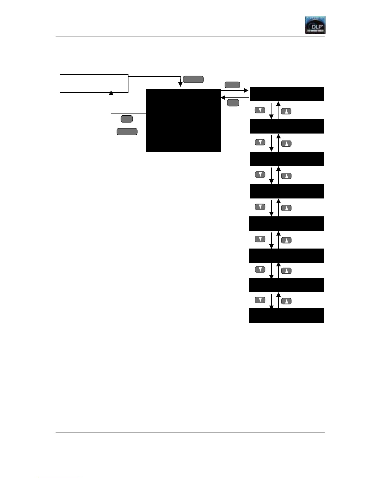
2.8. Picture adjustment menu
Adjusting below item s in video memory. Adjusted values can be reset by
NORMAL
NORMALNORMAL
NORMAL
button.
MENU1
MENU1MENU1
MENU1
button
MEMORY 1
BRIGHT -64 – 63 (0) Brightness setting
CONTRAST 0150 (100) Contrast setting
WHITE BALANCE L / M / H (M) White balance selection
GAMMA 0 – 4 (2) Gamma setting
DITHER ON/OFF (ON) Dither on/off
CSC NOR M / WH ITE / RGB (NORM) CSC selection
APERTURE ON / OFF (OFF) Aperture on/off
NR ON / OFF (OF F) Noise reduction on/of f
MENU2
MENU2MENU2
MENU2
button (Only when analog input is selected.)
MEMORY 1 Memory number
CLOCK Sampling clock setting
POSITION Position setting
CLAMP Clamp position setting
WHITE ADJU ST White level setting
V-MASK Vertical sync mask
position setting
SEPARATE SYNC synchronizing input setti ng
CLOCK setting
DIV 1500 – 1800 (1688) Sampling clock setting
FINE 0 – 127 (32) Sampling phase setting
FREQ UNDER / OVER 110MHz Sampling frequency setting
POSITION setting
H-POSITION 10 – 240 (163) Horizontal position s et ting
V-POSITION 3 – 60 (29) Vertica l position setting
CLAMP setting
C-POSITION 1 – 200 (80) Clamp position setting
C-WIDTH 27 – 100 (40) Clamp width setting
WHITE ADJUST setting
AUTO WHITE Automatic adjustment
MANUAL WHITE Manual adjustment
MANUAL WHITE setting
W-GAIN 0 – 254 (255) White gain setting
R-GAIN 0 – 254 (255) Red gain setting
G-GAIN 0 – 254 (255) Green gain setting
B-GAIN 0 – 254 (255) Blue gain setting
V-MASK setting
V-MASK START 1024 – 1280(1066) Vertical sync noise mask start
position
V-MASK END 0 – 31(7) Vertical sync noise mask end
position
SEPARATE SYNC setting
SEPARATE SYNC YES/NO Yes: direct sync no: separate sync
Page 18
First edition
18
Menu tre e
MENU1
MEMORY 1
BRIGHT 0
CONTRAST 100
WHITE BALANCE M
GAMMA 2
DITHER ON
CSC NORM
APERTURE OFF
NR OFF
ENTER
ENTERENTER
ENTER
Initial ima g e
MENU1
MENU1MENU1
MENU1
ESC
ESCESC
ESC
BRIGHT 0
WHITE BALANCE M
CONTRAST 100
DITHER ON
GAMMA 2
CSC NORMAL
APERTURE OFF
NR OFF
MENU1
MENU1MENU1
MENU1
ESC
ESCESC
ESC
Page 19

VS-SH10U Set-up and Installation Manual
19
MENU2
Initial imag e
ESC
ESCESC
ESC
ENTER
ENTERENTER
ENTER
DIV 1688
FINE 32
FREQ UNDER 110MHz
AUTO WHITE
MANUAL WHITE
AT-W ST AR T?
ESC
ESCESC
ESC
ENTER
ENTERENTER
ENTER
AT-W BUSY!
ESC
ESCESC
ESC
ENTER
ENTERENTER
ENTER
ENTER
ENTERENTER
ENTER
ESC
ESCESC
ESC
MEMORY 1
CLOCK
POSITION
CLAMP
WHITE ADJUST
V-MASK
SEPARATE SYNC
W-GAIN 255(128)
R-GAIN 255(128)
R-GAIN 255(128)
R-GAIN 255(128)
H-POSITION 163
V-POSITION 29
C-POSITION 80
C-WIDTH 40
AT-W FINISH!
V-M ASK START 1066
V-MASK END 7
SEPARATE SYNC YES
MENU2
MENU2MENU2
MENU2
MENU2
MENU2MENU2
MENU2
Page 20

First edition
20
2.9. Service menu
Pushing
ENTER
ENTERENTER
ENTER BBBB ESC
ESCESC
ESC
button displays service menu. After that you can select display/non-display
by
ESC
ESCESC
ESC
button. Pushing
ENTER
ENTERENTER
ENTER BBBB ESC
ESCESC
ESC
button once again cancels this mode.
Service menu setting items
SET CSC CSC adjustment
LAMP CHANGE Lamp data input, manual lamp change
W-GRADATION White gradation adjustment
R-GRADATION R, G, B gradation adjustment
SET WHITE BALANCE White balance adjustment
SENSOR Luminous sensor setting
LAMP PARAMETER Lamp parameter setting
SET CSC menu
(NORMAL / LAMP A) Title
R – R 0 – 1023 (1023)
R – G +/-255 (0)
R – B +/-255 (0)
G – R +/-255 (0)
G – G 0 – 1023 (1023)
G – B +/-255 (0)
B – R +/-255 (0)
B – G +/-255 (0)
B – B 0 – 1023 (1023)
LAMP CHANGE menu
SET LAMP DATA Change by up/down button.
Go to sub menu by ENTER button.
MANUAL CHANGE
SET LAMP DATA menu
SELECT LAMP Title
A:BUSY NEW
B:STANDBY NEW
Sub menu
(LAMP A)
LAMP TIMER RESET? Title
YES
NO
Sub menu
(LAMP A)
INPUT LAMP DATA Title
YR 511 Lamp dat a input
YG 511 Lamp data input
YB 511 Lamp data input
Sub menu
(NORMAL / LAMP A)
CSC CALCULATE OK? CSC auto-calculating
YES
NO
Page 21

VS-SH10U Set-up and Installation Manual
21
MANUAL CHANGE sub menu
MANUAL CHANGE OK? Select YES or NO by up/down button.
Execute by ENTER but ton.
YES
NO
W-GRADATION menu
W-TOP 0 Top adjustment
W-BOTTOM 0 Bottom adjustment
W-LEFT 0
Left adjustment
W-RIGHT 0
Right adjustment
W-TOP/LEFT 0
Top-left adjustment
W-TOP/RIGHT 0 Top- right adj ustment
W-BOTTOM/LEFT 0
Bottom-left adjustment
W-BOTTOM/RIGHT 0
Bottom-right adjustment
W-EDGE/TOP 0
Top edge adjustment
W-EDGE/BOTTOM 0 Bottom edge adjust ment
W-EDGE/LEFT 0
Left edge adjustment
W-EDGE/RIGHT 0
Right edge adjustment
R-GRADATION menu
R-TOP 0
Top adjustment
R-BOTTOM 0 Bottom adjustment
R-LEFT 0 Left adjustment
R-RIGHT 0 Right adjustme nt
R-TOP/LEFT 0
Top-left adjustment
R-TOP/RIGHT 0 Top- right adjustment
R-BOTTOM/LEFT 0 Bottom-left adjustment
R-BOTTOM/RIGHT 0 Bottom-right adjustment
R-EDGE/TOP 0
Top edge adjustment
R-EDGE/BOTTOM 0 Bottom edge adjustment
R-EDGE/LEFT 0 Left edge a djustment
R-EDGE/RIGHT 0 Right edge adjustment
Select R, G or B by R, G, B button.
SET WHITE BALANCE menu
WHITE BALANCE M Select ite ms by up/down button.
R-GAIN 0 – 1000
G-GAIN 0 – 1000
B-GAIN 0 – 1000
WHITE BALANCE default value
LOW MIDDLE HIGH
R-GAIN 1000 1000 700
G-GAIN 700 1000 700
B-GAIN 700 1000 1000
SENSOR menu
SENSOR ON/OFF DISABLE (OFF) Luminous sensor setting
SENSOR START? Luminous sensor initial value obtaining
Page 22

First edition
22
LAMP PARAMETER m enu
ERROR CODE Error information
WARNING OFF/TYPE 1/TYPE 2 Warning display type setting
CHANGE MODE NORMAL/LONG Lamp change mode setting
ERROR CODE menu
LAMP ERROR CODE Title
0000h Projector operating time at error detection
0000000000000000 Error information
0000h Projector operating time at error detection
0000000000000000 Error information
NORMAL KEY:RESET
Last couple of error information is indicated.
Detailed error information code
Bit15 Bit14 Bit13 Bit12 Bit11 Bit10 Bit9 Bit8 Bit7 Bit6 Bit5 Bit4 Bit3 Bit2 Bit1 bit0
bit0: error in lamp eject
bit1: error in lamp insert
bit2: reserved
bit3: reserved
bit4: luminous sensor fa ilure
bit5: reserved
bit6: reserved
bit7: reserved
bit8: reserved
bit9: reserved
bit10: not execute lamp initial position setting
bit11: not execute manual lamp exchanging
bit12: not execute brown-out la mp exchanging
bit13: not execute burn-out la mp ex changing
bit14: execute brown-out lamp exchanging (not error)
bit15: execute burn-out lamp excha nging (not error)
Page 23

VS-SH10U Set-up and Installation Manual
23
Menu tre e
Initial image
SET CSC
W-GARADATION
W-BOTTOM 0
W-TOP 0
R-GARADATION
SET LAMP DATA
MANUAL CHANGE
LAMP CHANGE
ESC
ESCESC
ESC
(NORMAL/LAMP A)
B – R 0
B – G 0
B – B 1023
(NORMAL/LAMP A)
R – R 1023
R – G 0
R – B 0
(NORMAL/LAMP A)
G – R 0
G – G 1023
G – B 0
ESC
ESCESC
ESC
ENTER
ENTERENTER
ENTER
ESC
ESCESC
ESC
or
ENTER
ENTERENTER
ENTER BBBB ESC
ESCESC
ESC
R-BOTTOM 0
R-TOP 0
ESC
ESCESC
ESC
ENTER
ENTERENTER
ENTER
ESC
ESCESC
ESC
ENTER
ENTERENTER
ENTER
ESC
ESCESC
ESC
ENTER
ENTERENTER
ENTER
Page 24

First editio n
24
Adjusted values can be saved when y ou exit the men u.
LAMP PARAMETER ERROR CODE
WARNING
CHANGE MODE
SENSOR SENSOR OFF
SENSOR START?
SET WHITE BALANCE
ESC
ESCESC
ESC
ENTER
ENTERENTER
ENTER
WHITE BALANCE M
R-GAIN 1000
G-GAIN 1000
B-GAIN 1000
ESC
ESCESC
ESC
ENTER
ENTERENTER
ENTER
ESC
ESCESC
ESC
ENTER
ENTERENTER
ENTER
SENSOR START
*****
ENTER
ENTERENTER
ENTER
SENSOR START?
Page 25

VS-SH10U Set-up and Installation Manual
25
2.10. Factory menu
Pushing
FUNC
FUNCFUNC
FUNC GGGG ESC
ESCESC
ESC
button displays factory menu.
Factory menu setting items
SET STANDARD CSC Standard CSC setting (factory use on ly )
VIEW STANDARD CSC Standard CS C display (factory use only)
BLACK LEVEL Black level adjust me nt
IMAGE FLIP Flipping vertical or horizontal
EDGE BLEND Edge blend setting (factory use only)
DISPERSION Dispersion filter setting (factory use only)
GRADATION Gradation setting (factory use only)
SET APERTURE Aperture setting (factory use only)
NO SIGNAL DISPLAY NO SIGNAL display setting (factory use only)
AUTO CLAMP START? * Auto clamp setting (factory use only)
AUTO WHITE START? * Auto white level setting (factory use only)
TEST BLANK * Blanking on/off setting (factory use only)
SET TIMER RESET? * Set timer value initializing (factory use only)
* These 4 items are indicated when dip switch no. 18 is O N or ME N U SW in FUNC + DISPLAY menu
is ON.
SET STANDARD CSC menu
(LAMP A) Title
SET OK?
VIEW STANDARD CSC menu
VIEW STANDARD CSC Title
CSC (NORMAL)
R – R 0 – 1023
R – G +/-255
R – B +/-255
G – R +/-255
G – G 0 – 1023
G – B +/-255
B – R +/-255
B – G +/-255
B – B 0 – 1023
VIEW STANDARD CSC Title
LAMP DATA
YR 511
YG 511
YB 511
BLACK LEVEL menu
R-LEVEL 0 – 32 Bla ck level in red se tting
G-LEVEL 0 – 32 Black level in green setting
B-LEVEL 0 – 32 Black level in blue setting
Page 26

First editio n
26
IMAGE FLIP setting
IMAGE FLIP N/E N/W S/E S/W (N/E) Flipping vertical or horizontal
EDGE BLEND setting
SELECT NON
TOP ON/OFF
LEFT ON/OFF
RIGHT ON/OFF
BOTTOM ON/OFF
DISPERSION setting
DISPERSION ON/OFF
GRADATION setting
GRAD-AUTO NONE!
SET APERTURE setting
APERTURE 1 0 – 3
APERTURE 2 0 – 3
NO SIGNAL DISPLAY setting
DISPLAY ON/OFF
AUTO CLAMP START? menu
AT-C BUSY!
AUTO WHITE START? menu
AT-W BUSY!
TEST BLANK setting
TEST BLANK ON/O F F
SET TIMER RESET? menu
RESET OK?
Page 27

VS-SH10U Set-up and Installation Manual
27
Menu tre e
EDGE BLEND
SELECT NON
TOP OFF
LEFT OFF
RIGHT OFF
BOTTOM OFF
DISPERSION
DISPERTION OFF
GRADATION GRAD-AUTO NONE!
BLACK LEVEL R LEVEL 0
G LEVEL 0
B LEVEL 0
VIEW STANDARD CSC
IMAGE FLIP
IMAGE FLIP N/E
SET APERTURE APERTURE 1 1
APERTURE 2 1
SET STANDARD CSC
ESC
ESCESC
ESC
ENTER
ENTERENTER
ENTER
(LAMP A)
SET OK?
VIEW STANDARD CSC
CSC(NORMAL)
R – R 1023
R – G 0
R – B 0
Initial image
ESC
ESCESC
ESC
FUNC
FUNCFUNC
FUNC GGGG ESC
ESCESC
ESC
ESC
ESCESC
ESC
ENTER
ENTERENTER
ENTER
ESC
ESCESC
ESC
ENTER
ENTERENTER
ENTER
ESC
ESCESC
ESC
ENTER
ENTERENTER
ENTER
ESC
ESCESC
ESC
ENTER
ENTERENTER
ENTER
ESC
ESCESC
ESC
ENTER
ENTERENTER
ENTER
ESC
ESCESC
ESC
ENTER
ENTERENTER
ENTER
ESC
ESCESC
ESC
ENTER
ENTERENTER
ENTER
Page 28

First editio n
28
SET TIMER RESET?
RESET OK?
AUTO WHITE START?
AT-W BUSY!
AUTO CLAMP START?
TEST BLANK
BLANK OFF
NO SIGNAL DISPLAY
ESC
ESCESC
ESC
ENTER
ENTERENTER
ENTER
DISPLAY OFF
AT-C BUSY!
ENTER
ENTERENTER
ENTER
ENTER
ENTERENTER
ENTER
ESC
ESCESC
ESC
ENTER
ENTERENTER
ENTER
ESC
ESCESC
ESC
ENTER
ENTERENTER
ENTER
Page 29

VS-SH10U Set-up and Installation Manual
29
3. Set-up and installation
3.1. Set-up & installation flow chart
Start
3.3 Dip switch setting
3.4 Multiple screen color space control (CSC) adjustment
3.5 Video signal adjustment
End
3.2 Picture outline adjustment
Page 30

First editio n
30
3.2. Picture outline adjustment
3.2.1. Displaying internal test signal for picture outline adjustment
Press TEST button on the rem ote control unit twice to display the internal test signal (crosshatch
for picture outline adjustment). This crosshatch signal indicates a crosshatch per 20 horizontal
pixels and per 16 vertical pixels.
There are also the lines for overlap setting for reference. They are located 5 pixels inside from
both horizontal ends and 4 pixels inside from both v ertical ends.
In the case of multi screen (without overlapp ing pixels) or s ingle scr een, ad just the picture outline
by 6-axis adjuster without projecting pixels outside the screen edge. If y ou require overlap setting,
adjust it in reference to the lines for overlap setting.
The number of pixels per screen is as follows.
Horizontal: 1,280 pixels
Vertical: 1,024 pixels
20 pixels
16 pixels
4 pixels
5 pixels
Page 31

VS-SH10U Set-up and Installation Manual
31
B: T/B PHASE
3.2.2. Adjusting 6 axes
(In the case of using optional 6-axis adjuster, S-050AXI)
Loosen the 6 lock screws with the hexagon wrench (2 m m) before the adjustment.
Adjust each axis with the hexagon wrench (3m m).
View from the screen
Adjustment screw Clockwise Counterclockwise
1. Tilt the image.
2. Form the vertical keystone
distortion.
3. Form the horizontal keystone
distortion.
4. Adjust the v ertical position.
5. Adjust the horizontal position.
6. Scale up/down the image.
A
: TILT
D: V-POSI
B: T/B PHASE
E: H-POSI
C: H-KEYS
A
: TILT
C: H-KEYS
D: V-POSI
E: H-POSI
F: ZOOM
F: ZOOM
Page 32

First editio n
32
3.2.3. Picture outline adjustment steps
Perform the picture outline adjustment roughly for each sing le
screen.
1. After making the image size s maller than the outline of the
screen using the zoom axis, adjust TILT, V-POSI, and H-POSI
so that upper and lower spaces and right and left spac es
shifted by the 6-axis adjuster will be almost equalized
respectively with each other.
A=A', B=B'
2. After forming the horizontal keystone distortion, adjust the
image position to the center of the screen with V -P O SI.
3. After forming the vertical keystone distortion, adjust the image pos ition to the center of the
screen with H-POSI.
4. Adjust the image size to the outline of the screen.
After adjusting roughly on each sing le screen, ad just finely
on the multi screen.
5. Adjust finely so that each screen edge will link without
distance.
Adjust the vertically shift e d
image position to the center of
the screen.
Form the horizontal keystone
distortion.
A
A
'
B
B
'
Adjust the horizontally shifted
image position to the center of the
screen.
Form the vertical keystone
distortion.
Page 33

VS-SH10U Set-up and Installation Manual
33
3.2.4. For delivery
Tighten the 6 lock screws in each ad justing screw w ith the
hexagon wrench (3mm) before shipping the pr odu ct.
Shipping the product without locking the adjuster may
cause breakage.
3.3. Dip switch setting
Setting set-up switch according to the system configuration before turning ON the main power.
See “Dip switch setting” on page 12 in Product Description. Be sure to turn OFF the main power
if you wish to change the setting in the middle of the operation. Only turning ON the main power
will renew the setting.
3.4. Multiple screen color space control (CSC) adjustment
Adjusting the luminance and tint between each screen of the multi screen. In principle, the
adjustment should be according to (2) CSC Adjustment, however, follow (1) Black level
adjustment, (3) White balance adjustment and (4) gradation adjust ment, if necess ary.
Multi-screen adjustment flow
3.4.1. Black level adjustment
NOTE: This adjustment is not ne cessary unless the difference of the luminance and ti nt i n
black is noticeable between e ach screen. Be careful not to deteriorate the contrast
because it can be adjusted only by increasing the black luminance level.
[Input signal] Built-in test signal: Black signal in the adjustment white. Press
TEST
TESTTEST
TEST
button once
and press
RRRR GGGG BBBB
buttons (See “Test pattern display” on page 16 and “RGB color
mute” on page 16).
[Adjustment]
1) Display the factory menu (See “Factory menu” on page 25) and select BLACK LEVEL.
2) Adjust red, blue within the range of 0 to 3, green w ithin the rang e of 0 to 2 approx imate ly.
3.4.2. CSC adjustment
* If you adjust CSC after lamp changing, please refer “CSC calculating” on page 42.
[Input signal] Built-in test signal: Adjustment white (See “Test pattern display” on page 16: press
TEST
TESTTEST
TEST
button once)
Use
RRRR GGGG BBBB
buttons on the remote control unit to display the monochrome color.
[Adjustment]
1. Select CSC in menu 1 (S ee “Pro je ctor infor mation display” on page 15) and select NORM,
WHITE or RGB. (3 patterns of CSC data between the multi screen can be saved.)
2. Select SET CS C in s erv ice menu (Se e “Service menu” on page 20).
3. Display the monochro me re d and a djust the lu m inance level finely by decreasing R – R of
the brighter screen, according to the darkest screen, if the luminance differs betw een e ach
CSC adjustment
See (2)
Black level adjustment
See (1)
White balance
adjustment See (3)
Lock screw (6 points)
Gradation adjustment
See (4)
Page 34

First editio n
34
screen. (If decreasing the luminance excessively, increase R – R.)
4. Adjust the tint on the monochrome red fine ly by increasing or de creas in g R – G, R – B if the
tint differs between each screen.
5. Display the monochrome green and adjust the luminance level finely by decreasing G – G of
the brighter screen, according to the darkest screen, if the luminance differs betw een e ach
screen. (If decreasing the luminance excessively, increase G – G.)
6. Adjust the luminance level on the monochrome gre en finely by increasing or decreasing G –
R, G – B, if the tint differs between each screen.
7. Display the monochro me b lue and adjust the luminance level finely by decreasing B – B of
the brighter screen, according to the darkest screen, if the luminance differs betw een e ach
screen. (If decreasing the luminance excessively, increase B – B.)
8. Adjust the tint on the monochrome blue finely by increasing or decreasing B – R, B – G, if the
tint differs between each screen.
9. Display yellow (red plus green) and adjust the tint finely by increas ing or decrea sing R – R,
G – G, if the tint differs between each screen.
10. Display magenta (red plus blue) and adjust the tint finely by increasing or decrea sing R – R,
B – B, if the tint differs between each screen.
11. Display cyan (green plus blue) and adjust the tint finely by increasing or decreas ing G – G, B
– B, if the tint differs between each screen.
12. Display white and adjust the tint finely by increasing or decreasing R – R, G – G and B – B.
13. Repeat the steps from 3) to 11) so as to un ifor m the luminance and tint of all the colors.
CSC adjustment menu
Adjustmen t value
Menu
(OSD)
Increase Decrease
Displayed color
R – R Increasing red luminance Decreasing red luminance Red, Yellow, Magenta, White
R – G Making red yellowy Making red less yellowy Red
R – B Making red bluish Making red less bluish Red
G – R Making green yellowy Making green less yellowy Green
G – G Increasing green luminance Decreasing green luminance Green, Yellow, Cyan, White
G – B Making green bluish Making green less bluish Green
B – R Making blue reddish Making blue less reddish Blue
B – G Making blue greenish Making blue less bluish Blue
B – B Increasing blue luminance Decreasing blue luminance Blue, Magenta, Cyan, White
Page 35

VS-SH10U Set-up and Installation Manual
35
3.4.3. White balance adjustment
NOTE: In principle, this adjustment is unnecessary because the luminance/ti nt l evel
between each screen of the m ult i screen is adjusted in CSC adjustment. However,
adjust the white balance to change the color temperature or adjust finely after CS C
adjustment.
[Input signal] Built-in test signal: Adjustment white (See “Test pattern display” on page 16: press
TEST
TESTTEST
TEST
button once)
To display the monochr ome color, press
RRRR GGGG BBBB
in the remote control unit.
[Adjustment]
1. Select SET WHITE BALANC E in service menu (See “Service menu” on pag e 20) and select
from among HIGH, MIDDLE, and LOW.
2. Adjust R, G and B GAIN.
White balance adjustment display
3.4.4. Gradation adjustment
NOTE: In principle, this adjustment is unnecessary because the luminance/ti nt l evel
between each screen of the mul t i screen i s adjusted in CSC adjustment. Be careful
not to deteriorate the uniformity in a screen.
[Input signal] Built-in test signal: Adjustment white (See “Test pattern display” on page 16: press
TEST
TESTTEST
TEST
button once)
[Adjustment]
1. Select R/G/B-GRAD ATION in service menu (See “Service menu” on page 20).
2. Compensate differences of lumi nance/tint level between each s creen in red, green and blue.
Be careful about uniformity in a screen.
3. Add finishing on the fringe of screens to har m on iz e w ith the whole m ulti vision system.
Notice:
W-GRADATION adjustment is usually unnecessary unless R/G/B-GRADATION adjustment is
doing well.
Each adjustment should be in an adequate range. Adjustment value should be stayed within the
confines of –50 to 50, even though whole range is –128 to 127.
WHITE BALANCE M
R-GAIN 1000
G-GAIN 1000
B-GAIN 1000
Page 36

First editio n
36
ccbb
1
43
2
ab
c
b
c
b
b
ba
a
b
a
Gradation adjustment point
1
43
2
Adjustment item
R/G/B-TOP
R/G/B -BOTTOM
R/G/B -LEFT
R/G/B -RIGHT
A
R/G/B -TOP/LEFT
R/G/B -TOP/RIGHT
R/G/B -BOTTOM/LEFT
R/G/B -BOTTOM/RIGHT
B
R/G/B -EDGE/TOP
R/G/B -EDGE/BOTTOM
R/G/B -EDGE/L EFT
R/G/B -EDGE/ RI GHT
C
MENU2 adjustment display
(Displayed only when analog is input.)
Gradation adjustment procedure
(4-screen multi vision as an example)
1. Adjust to match the luminance/tint level in the edge of
adjacent screens (gray area in the lower left figure)
using adjustment item A and C. In this time, adjust to
align darker part with brighter one with considering
uniformity in a screen.
2. Adjust to match the luminance/tint level in the 4
corners connecting area (area a in the lower right
figure) using adjustment item B.
3. Adjust to match the luminance/tint level in the fringe of
screens (area b and c in the lower right figure) using
adjustment item A and C at first, then compensate it
with B.
4. Repeat the steps from 1) to 3) so as to unifor m the luminan ce/tint leve l of all colors.
3.5. Video signal adjustment
3.5.1. Memory select
Select the memory number to save adjusted values in. The memory can be selected from 01 to
16 by pressing
MEM LIST
MEM LISTMEM LIST
MEM LIST
and 01 – 16 in number buttons (See “Video memory select” on p age 15).
Selected memory number is displayed at the top of MENU1 and M ENU 2. If you don’t select the
memory number, the values are saved in MEMORY1. If MENU 1 and ME N U2 setting ha s bee n
changed, pressing
ESC
ESCESC
ESC
button will display OSD (shown below) on which you can choo se to
save the data in the selected memory.
3.5.2. MENU2 adjustment (Only when analog is input)
The adjustment display shown below will be disp layed by pressing
MENU2
MENU2MENU2
MENU2
button if analog
input is selected (See “Picture adjustment menu” on page 17). Pres s
ESC
ESCESC
ESC
button to activate
the normal mode.
MEMORY 1
CLOCK
POSITION
CLAMP
WHITE ADJUST
V-MASK
SEPARATE SYNC
ADJUSTMENT VALUE SAVED?
YES
NO
Page 37

VS-SH10U Set-up and Installation Manual
37
3.5.2.1. SEPARATE SYN C adjustment:
[Adjustment]
5. Select SEPARATE SYNC in MENU2.
6. Select YES w he n 5-line signal is input. If the menu is not displayed corre ctly , select NO. If
3-line signal (SYNC on green) or 4-line signal (composite SY N C) is input, select NO.
3.5.2.2. CLAMP adjustment:
Adjust CLAMP when the picture is dark or the br ightness o f the whole screen is not normal.
The picture is dark The picture has the abnormal brightne ss
[Adjustment]
1. Select CLAMP in MENU2.
2. Adjust so as to normalize the brightness of the picture.
3.5.2.3. V-MASK adjustment:
V-MASK adjustment is required if the upper part of the
picture is distorted.
[Adjustment]
1. Selec t V-MASK in MENU2.
2. Adjust so as to normalize the picture. Set V-MASK-
START at the maximum value which nor malizes the
picture. Set V-MA SK-END at the minimum value
which normalizes the picture.
3.5.2.4. CLOCK adjustment:
Adjusting the phase of the sampling clock and the total dot number in the hor izontal direction of
the input signal. Display the detailed pattern that can change w ith ea ch dot in the horizontal
direction. (When the input signal is output via Windows, display the screen with “Shut Down
Windows” dialog box.) V ertical ly striped noise will appear on the picture if DIV value is incorrect.
As DIV value nears optimum, the number of vertical lines on the picture d ecre ases. And the
noise will disappear as the value becomes optimum. Incorrect FI NE v alue causes noise on the
whole screen.
Distortion on the upper part of the
Page 38

First editio n
38
[Adjustment]
1. Select CLO CK in MENU2.
2. Adjust DIV so that vertically striped noise on the p icture wi ll disapp ear.
3. Select FI NE i n C LOCK.
4. Adjust FINE finely so that snowy nois e on the w ho le p icture will disappear.
Normally adjust it within the range of 0 to 31. However, Set FINE in the range of 32 to 127 if Vdancing appears by optimising FINE value.
3.5.2.5. WHITE ADJUST adjustment:
Adjusting the input level GAIN of analog signal.
[Adjustment]
1. Input full-white video signal.
2. Select AUTO WHITE in WHITE ADJUST in MENU2 and start A UTO WHITE.
[When “OVERFLOWED" is displayed]
OVERFLOWED will be dispayed if the input signal level is not in the adjustment rang e such as
when the level of input video signal is too high or too low, or full-white sign al is not input. In such
cases, it is required to input the signal of the optimum level.
[Manual Adjustment]
Manual adjustment is possible in MANUAL WHITE menu if full-white video signal can not be
input. The value can be reset to the value adjusted at factory before shipp ing by press in g
NORMAL
NORMALNORMAL
NORMAL
button.
3.5.2.6. H-POSITION/V-POSITION adjustment
Adjusting the horizontal and vertical phase of input signal.
[Adjustment]
1. Select H- PO SITION in MENU2.
2. Adjust so that all the horizontal pixels will be displayed.
3. Select V-POSITION in MENU2.
4. Adjust so that all the vertical pixels will be displayed.
Noise caused by incorrect
CLOCK adjustment
Noise caused by incorrect
FINE adjustment
Page 39

VS-SH10U Set-up and Installation Manual
39
3.5.3. MENU1 adjustment (effective for both analog and digital input)
The adjustment display will be displayed b y pressing
MENU1
MENU1MENU1
MENU1
button. Press
ESC
ESCESC
ESC
button to
activate the normal mode. If any value is changed in MENU1, the value will be saved in the
memory number displayed at the top of MENU1 (The va lue will be saved in M EMORY1 if the
display is shown below).
MENU1 adjustment display
3.5.3.1. DITHER adjustment
Turning ON/OFF DITHER. Normally keep it ON.
[Adjustment]
1) Select DITHER in MENU1.
2) Select ON or OFF.
3.5.3.2. BRIGHTNESS adjustment
Normally unnecessary to adjust the brightness. You can adjust the brightness of darker part of
the picture. However, darkening the picture excessively deteriorates the tone characteristics of
the darker part of the picture. Press
NORMAL
NORMALNORMAL
NORMAL
button to reset the value to the value adjusted
before shipping from factory.
[Adjustment]
1. Select BRIGHTNESS in MENU1.
2. Change the adjust me nt value.
3.5.3.3. CONTRAST adjustment
Normally unnecessary to change the contrast. You can adjust the picture darkness and
brightness with this adjustment. However, darkening the picture excessively deteriorates the
tone characteristics. Press
NORMAL
NORMALNORMAL
NORMAL
button to reset the value to the value adjusted before
shipping from factory.
[Adjustment]
1. Select CONTRAST in MENU1.
2. Change the adjust me nt value.
3.5.3.4. APERTURE setting
This is use for edge enhancement. Normal setting is OFF.
3.5.3.5. NR setting
This is use to reduce subtle noise in analog signal etc. Normal setting is OFF.
MEMORY 1
BRIGHT
CONTRAST
WHITE BALANCE
GAMMA
DITHER
CSC
APERTURE
NR
Page 40

First editio n
40
4. Auto lamp changer
4.1. Overview of lamp changer
Operation panel
MANUAL button: To start manual lamp change.
OPEN LED: Turning on in manual lamp change mode.
ERROR LED: Turning on at error detection of lamp position sensor, lamp transit motor circuit or
lamp power supply.
INSERT/EJECT button: To transfer lamp inside or outward. They are effective only w hen
corresponding lamp lid is open and OPEN LED is on. Lighting la mp does not move by these
buttons. To prevent malfunction, INSERT button is hard to push without acuminate tool like
ballpoint pen.
4.2. Caution
• Replace the lamp with as less pressure as possible on the optical engine not to swerve 6-
axis adjustment.
• Never look into the lamp while it is o n .
• Never touch the glass envelope of the lamp with your fingers. The oil on your fingers may
cause damage or explosion of the lamp.
• Never touch the lighting lamp because the temperature of the lamp gets very high.
• Never touch the metal part of the lamp connector because a high pressure arises ther e.
• Just open the lamp lid either A or B, which corresponds to the replacing lamp. If you replace
both, replacing work should be done sep arately.
• Replace the lamp with drawing on thick glove. The lamp is heated for a while even if the
lamp is turned off.
Lid A (for lamp A replacement)
Lid B (for lamp B replacement)
Operation panel
Page 41

VS-SH10U Set-up and Installation Manual
41
4.3. Spare lamp cartridge replacing/adjusting procedure
4.3.1. Record new lamp data
Record new lamp data that is indicated in the bottom of the lamp
cartridge in advance.
4.3.2. The lamp to replace confirmation
Confirm which lamp should be replaced. In lamp A or B, indication “USED” or “JUNC” lamp is
relevant to it by pushing DISPLAY button on remote control (If there is no such indication in it,
please check the error reason at “ERROR COD E” in LAMP PAR AMETER in service menu (refer
to “Service menu” on page 20)). “BUSY” lamp means lighting lamp.
4.3.3. Lid detaching
1. Loosen 3 fixing screws on the lid for the lamp to replace and
detach the lid.
2. Confirm OPEN L E D in operation panel is on.
4.3.4. Lamp pulling out
1. Push EJECT button of relevant lamp in operation panel to pull
out it till la mp cartridge is o u t o f g ear. ( L a mp cartridge wo uld
automatically move inside in the middle of gear .)
2. Pick out the lamp cartridge along the rail
3. Disconnect the lamp conne ctor.
4.3.5. New lamp inserting
1. Confirm new lamp data, YR, YG and YB is recorded once again.
2. Connect the new lamp connector securely.
3. Insert the new lamp cartridge along the rail. After touching the gear, giving a light press
automatically moves the cartridge inside.
4.3.6. Lid attaching
1. Close the lamp lid and tighten up the 3 fixing screw s.
2. Confirm OPEN L E D in operation panel is off. (If OPEN LED is still on, auto lamp changing
function is not effective. Please check whether the lid closes completely.
Page 42

First editio n
42
4.3.7. Lamp timer confirmation
Record lamp timer value as needed with pushing FUNC + DISPLAY button. The value means the
operation time of the replaced old lamp.
4.3.8. CSC calculating
1. Select SET LAMP DATA in LAMP CHANGE in service menu.
2. Select replaced lamp A or B in SET LAMP DATA sub menu
3. Select YES in LAMP TIMER RESET?, then input recorded la mp data, YR, YG and YB in
INPUT LAMP DATA menu.
4. Pressing ENTER changes to CSC CALCULATE OK? and select YES.
4.3.9. Lamp exchanging
Push MANUAL button or select YES in MANUAL CHANGE? in MANUAL CHANGE in LAMP
CHANGE in service menu to exchange current lamp to new one for adjustm ent. Co nfir m the
exchanged lamp lights. Exchanging time t a kes about 50 seconds from old lamp turning off to
new image display (refer to “Lamp exchanging time” on page 44).
4.3.10. CSC manual adjustment
If necessary, adjust CSC finely according to the procedure in “CSC ad just me nt” on p age 33.
4.3.11. Gradation adjustment
If necessary, adjust gradation finely according to the procedure in “Gradation adjustment” on
page 35.
4.3.12. Lamp exchanging
Lamp adjustment has finished. Put back current lamp in the same procedure as ch apter 4.3.9.
4.3.13. Error code erasing
1. Con f irm error informa tion in ERROR CO DE in LAMP CHANGE in service menu. An y errors
except normal lamp change executing ar e displayed, please record the information and
timer value.
2. Reset the error code by pushing NORMAL button and ENTER button. (If it isn’t reset,
warning is continuously displayed.
3. Confirm replaced lamp bec o me s NEW in lamp status menu by pushing DISPLAY button. (If
the status is “USED” or “JUNC”, lamp timer might not be reset. Please reconfirm the
operation of chapter 4.3.8 “CSC calculating.”
4.4. Auto lamp change action
4.4.1. At lamp burn-out
The lamp changer can detect lamp burn-out and exchange to new lamp auto matica lly. It judges
by lamp drive circuit signal and luminous sensor after 2 times ignition to check burn-out or not.
The luminous sensor is effective 5 minutes after the pro jector’s turn ing on.
Page 43

VS-SH10U Set-up and Installation Manual
43
1. Lamp control state chan ges light off if it judges lamp burn-out.
2. The state of burn-out la mp is automatica lly recognized as “JU N C.”
3. It automatically confirm the state of reserved lamp is “NEW.” (If the state is “JUNC,” the auto
lamp change action stops and the projector turns off. The error is noticed on LED in circuit
box (indication is “1.” (refer to “LED display” on page 14)) and on the screen to call service
person (refer to “Warning message” o n page 44).
4. It exchanges the current burn-out lamp for the reserved new la mp.
5. It turns on the new lamp.
4.4.2. At lamp brown-out
The lamp changer can measure the luminous deterioration by luminous sensor and exchange to
new lamp automatically. The sensitivity setting can be selected LO NG (30% down from initial
value) or NORMAL (50% down fr om initial value). You can also set the preannounce message on
the screen (refer to “Warning message” o n page 44).
The initial value of lamp luminance is measured automatically 5 minutes after the auto lamp
change. If you turn off in the process of lamp changing, it measures similarly after reboot. If you
exchange lamp by manual, you have to meas ure it in SENS OR menu in service menu. It should
be measured 5 minutes after lamp turning on.
1. It confirms lamp brown-out by luminous sensor.
2. It notices lamp changing preliminary on the screen. (You can select no indication setting.)
3. It turns off the lamp 5 minutes after the brow n-o ut con firmation.
4. The state of brown-out lamp is auto matically recog nized as “US E D.”
5. It automatically confirm the state of reserved lam p is “NEW.” (If the state is “USED” or
“JUNC,” the auto lamp change action stops. The error is noticed o n the scre en to call serv ice
person (refer to “Warning message” o n page 44).
6. It exchanges the current brown-out lamp for the reserv ed new la mp.
7. It turns on the new lamp.
4.5. Manual lamp change action
Regardless of lamp burn-out or brown-out, the lamp chan ger can exchange the lamp by manual.
The lid should be close during the operation.
4.5.1. At lamp lighting
1. Push MANUA L button in operation panel or select YES in MANUAL CHANGE O K? in
MANUAL CHANGE in LAMP CHANGE in service menu.
2. It turns off the lamp.
3. It exchanges the current lamp for the reserved new lamp.
4. It turns on the new lamp.
4.5.2. At stand-by mode
1. Push MANUAL button in operation panel.
2. It turns on the projector automatically.
3. It exchanges the current lamp for the reserved new lamp.
4. It shuts down to get back to stand-by mode.
Page 44

First editio n
44
LAMP WILL BE CHANGED
AFTER 5 MIN
4.6. Information display
4.6.1. Warning message
The lamp changer can notice the indication to call service person and the pre-ann oun cement of
lamp exchanging. It can be set from the 3 types as below in WARNING in LAMP PARAMETER in
service menu (refer to “Service menu” on page 20).
OFF: Nothing to display on the screen.
TYPE 1: Display only the indication to call service pers on
TYPE 2: Display both indications to call service person and the pre-an nouncement of lamp
exchanging.
[The indication to call service person]
The indication blinks every 15 seconds w hen some errors occur and
it is required to call service person.
[The pre-announcement of lamp exchanging]
This message is displayed when the lamp is brown-out. It count s
down from 5 to 0, then starts lamp exchang in g.
4.6.2. Operation time and error indication
It can display error information and projector operating time at error detection in service menu
(refer to “Service menu” on page 20). Last couple of error information is indicated.
4.7. Lamp exchanging time
If it fails lamp ignition, it retries till 6 times at start-up and 2 times in the middle of normal
operation.
It takes several tens of seconds from projector turning on to lamp turning on.
In the case of lamp ignition failure, it retries after 55 seconds interval according to the
specification that lamp manufacturer recommends.
The time of lamp off Almost recover the luminance
At lamp brown-out 50 sec to 2 min 40 sec 1 min 20 sec to3 min 10 sec
At lamp burn-out 2 min 40 sec to4 min 30 sec 3 min 10 sec to5 min
Page 45

VS-SH10U Set-up and Installation Manual
45
5. Communication protocol
5.1. Communication rules
1. Flow control : None
2. Bits per second : 19,200bps/ 9,600bps (Selectable by dip switch)
3. Parity : None
4. Data bits : 8bits
5. S t op b it s : 1bit
5.2. Command character strings
A com mand is defined by ASCII characters. It consists o f a com m and ID n umber, a command
name and zero or more parameters. A carriage return ( CR) c ode (0Dh) is added at the end of
each command. The comma nd ID and the command name shall not be delimited. Case
sensitivity is on.
ID Command [ Parameter1 ]¥r
Example: 01vP1 ¥r
Note: “¥r” stands for a CR code (0Dh).
5.3. Command ID
Command ID represents unit ID o f controlled pro jectors by tw o decim al dig it ASCII characters.
The unit ID can be set by the dip switch of the unit in the range of 01 to 32. When a command
with a command ID “00” is sent, all connected projectors execute the command at once. Only
when the command ID correspon ds with the ir unit ID or when the co mmand ID is “00”, Pro jectors
execute the command.
5.4. Sequence
After receiving the CR code (0Dh), the projector analyzes and executes the com mand w ithin 700
msec, and starts to transfer the result string. However, if the command ID does not correspond
with the unit ID, the projector will not return any result string.
When the projector receives a command with a command ID “00”, it will return the result string. If
the master function is not set effective, it will not return any result string.
When the projector is processing a command, the host shall not issue any command. (The
period of receiving result string or 700 msec after CR code transmission, wh ichever shorter is
regarded as the time the projector is processing the command by the host.)
* As for some commands, it might take more than 700 msec till the projector returns the result
string after receiving a command.
Page 46

First editio n
46
01i0¥r
01i0¥r
01NP1¥r
A
nalyzing and executing the command within 700 msec.
ProjectorsExternal controller
01NP1¥r
00NP0¥r
(Note) ¥r stands for a CR code.
100 msec or less
50 msec or more
00NP0¥r
When command ID “00” is sent, only the
projectors whose master function is set
effective will respond to the command.
A
nalyzing and e xe cu t in g th e c omma nd within 700 msec.
5.5. Command return value
Projectors return command execution results with AS CII character strings. A result string consists
of an ID number , comm and na me and z ero or more return v alues. A CR code is adde d at the end
of each result string. The ID number and the com mand name shall not be delimited. The ID
number represents unit ID by two decimal digit ASCII characters.
When the projector receives a command with a command ID “00”, it will return the result string. If
the projector receives an undefined command, it will not return any result string. If the master
function is n o t s e t effective , it will not return any result st r in g .
The result strings which are returned in response to the command with the ID number “00” w i ll
contain the ID number “00”.
ID Command [ Parameter1 ]¥r
Example: 01vP1 ¥r
Note: “¥r” stands for a CR code (0Dh).
Attention
An inexecutable error may be returned when there is O SD indication such as a remote controller
adjustment menu.
Page 47

VS-SH10U Set-up and Installation Manual
47
5.6. Control commands
5.6.1. vP (Power)
Function: To control power supply
Format:
ID vP [Power]
Control power on/off
0 The projector moves to the stand-by mode when it is in the
normal mode or the start-up process.
1 The projector moves to the start-up process when it is in the
stand-by mode.
Power
Omitted The projector returns current mode.
Response: ID vP mode
Current power control status
0 Termination process, stand-by mode
mode
1 S tart-up process, normal mode
[Note]
After completion of turning on, it is desirable to issue other control command with confirming that
start-up process is finished and system is steady state. You can confirm the processing state by
[vS] command.
Sequence of turning on process Sequence of turning off process
01vP0 ¥r
01vS ¥r
01vS4 ¥r
01vS ¥r
01vS2 ¥r
External controller Projectors
01vP0 ¥r
External con troller
01vP1 ¥r
01vP1 ¥r
01vS ¥r
01vS18 ¥r
01vS ¥r
01vS14 ¥r
01i0 ¥r
01i0 ¥r
Projectors
Page 48

First editio n
48
5.6.2. NP (Picture Mute)
Function: To control picture mute. The projector accepts this command even in the stand-by
mode. If the projector receives NP command in st and-by mode, it automatically
executes it after start-up process. The picture mute status is cancelled by executing
[vP0] command or turning off the main power.
Format:
ID NP [Mute]
Mute on/off control
0 Mute cancel
1Mute
Mute
Omitted Returning current mode
Response: ID NP mute
Current mute status. The projector does n ot respon d to the m ute cau sed
by no signal.
0 Mute cancel
mute
1 Mute status
5.6.3. i (Input Select)
Function: To select display input port. It is only available in steady state.
Format:
ID i [Sel]
Select input port
0 Analog input
1 Digital input
Sel
Omitted Returning current setting value.
Response: ID i sel
selected current input port
0 Analog input
sel
1 Digital input
5.6.4. iE (Input Port Save)
Function: To save current input port selection. On next start up, the input port is set according to
the saved data. If you change input port selection by remote control, the status is
automatically saved. It is only available in steady state.
Format:
ID iE
Response:
ID iE
Page 49

VS-SH10U Set-up and Installation Manual
49
5.6.5. n(Memory Select)
Function: To change memory number. It is only available in steady state.
Format:
ID n [Sel]
Select memory nu mb er
0 – 15 Memory number
Sel
Omitted Returning current setting value.
Response: ID n sel
selected current memory numbersel
0 – 15 Memory number
5.6.6. nE (Memory Save)
Function: To save current memory selection. On next start up, the memory number is selected
according to the saved data. If you change memory selection by remote control, the
status is automatically saved. If you change input port selection by remote control, the
memory selection might change. It is only available in steady state.
Format:
ID nE
Response:
ID nE
5.6.7. nA (Analog Input, Memory Select)
Function: To change memory number with chang ing input port to analog at the same time. It is
only available in steady state.
Format:
ID nA [Sel]
Select memory nu mb er
Sel
0 – 15 Memory number
Response: ID nA sel
selected current memory numbersel
0 – 15 Memory number
5.6.8. nD (Digital Input, Memory Select)
Function: To change memory number with chang ing input port to digital at the same time. It is
only available in steady state.
Format:
ID nD [Sel]
Select memory nu mb er
Sel
0 – 15 Memory number
Response: ID nD sel
selected current memory numbersel
0 – 15 Memory number
Page 50

First editio n
50
5.6.9. vS (System Status)
Function:To get system status information.
Format:
ID vS
Response:
ID vS info
Get current operational status
0 Error
1 System I nitializing
2Stand-by mode
3 Reserved
4 Shutdown process
5 Shutdown process
6 Reserved
7 Reserved
8 Initializing
9 Turning projector on
10 Turning DMD on
11 Reserved
12 Reserved
13 Steady state ready
14 Steady state
15 Steady state (no signal)
16 Reserved
17 Reserved
18 Lamp exchanging p os ition setting process
19 Adjust value calculating
20 Adjust value calculating
21 Adjust value calculating
22 Memory changing
23 Power failure
24 Reserved
25 Reserved
26 Other processing
27 General lamp re-lighting sequ enc e
28 Lamp re-lighting
29 S tart-up error recovering
info
30 – 35 Reserved
Page 51

VS-SH10U Set-up and Installation Manual
51
5.6.10. e(Error Detection)
Function: To get error states. If error is detected, system automatically starts shutdown process
and becomes stand-by mode. Detected error status is obtained in stand-by mode.
Detected errors are cleared on next start-up. If any errors are detected again, system
replies the error information. If not, it replies “no error.”
Format:
ID e
Response:
ID e info
Last detected error information
0 Fan stop
1 Lamp changer mechanical failure or no workable lamp
2 DMD control circuit failure
3 DMD control circuit failure
4 Lamp changer control circuit failure
5 Internal SRAM failure
6 (not defined)
7 Power failure
info
n No error
5.6.11. ISA (Lamp-A Status)
Function:To get lamp-A st atus.
Format:
ID ISA
Response:
ID ISA status
Lamp-A status
0New
1Used
status
2Junk
5.6.12. ISB (Lamp-B Status)
Function:To get lamp-B status.
Format:
ID ISB
Response:
ID ISB status
Lamp-B status
0New
1Used
status
2Junk
Page 52

First editio n
52
5.6.13. ST1 (Status Information)
Function:To get projector status information.
Format:
ID ST1
Response:
ID ST1 info
Indicate status with HEX2 bytes ASCII code corresponding to 8 bitsinfo
00 – ff The functions of each bit are as follows.
bit7 bit6 bit5 bit4 bit3 bit2 bit1 bit0
r r r p-seq mt change light signal
signal
0: input signal on
1: input signal off
* It is uncertain value, if p-seq bit is 1.
light
0: lamp turning off
1: lamp turning on
* It is uncertain value, if p-seq bit is 1.
change
0: lamp exchanging prenotice off
1: lamp exchanging prenotice on
mt
0: maintenance request off
1: maintenance request on
The detailed maintenance request can be o btained by MT
command.
STR2 command execution sets “0”.
p-seq
0: sig, light information is available
1: sig, light information is invalid. (It sometimes occurs on
start-up process.)
r: reserved
5.6.14. ST2 (Lamp Timer Value)
Function:To get lamp timer value.
Format:
ID ST2
Response:
ID ST2 time
Indicate lamp timer value with HEX6 bytes ASCII code.time
000000 – ffffff Lamp timer value
Example:
If lamp timer value is 961 hours,
ID ST2 0003c1 ¥r (“¥r” stands for a CR code (0Dh))
Page 53

VS-SH10U Set-up and Installation Manual
53
5.6.15. ST3 (Set Timer Value)
Function:To get set timer value.
Format:
ID ST3
Response:
ID ST3 time
Indicate set timer value with HEX6 bytes ASCII code.time
000000 – ffffff Set timer value
Example:
If set timer value is 961 hours,
ID ST3 0003c1 ¥r (“¥r” stands for a CR code (0Dh))
5.6.16. STR1 (Lamp Timer Reset)
Function:To reset lamp timer value.
Format:
ID STR1
Response:
ID STR1
5.6.17. STR2 (Mt Bit Reset)
Function:To reset mt bit in ST1 command. “Info: time” parameter in MT command is also reset at
the same time.
Format:
ID STR2
Response:
ID STR2
Page 54

First editio n
54
5.6.18. MT (Maintenance request information)
Function:To indicate error information of luminance sensor and lamp exchanging, result o f lamp
exchanging execution and set timer value.
Format:
ID MT
Response:
ID MT info: time
Indicate error information and lamp exchanging execut ion resu lt.
info
0000 –
ffff
Indicate status with 4 bytes ASCII code corresponding to 16 bits.
bit15 bit14 bit13 bit12 bit11 bit10 bit9 bit8 bit7 bit6 bit5 bit4 bit3 bit2 bit1 bit0
mtf mte mtd mtc mtb mta mt9 mt8 mt7 mt6 mt5 mt4 mt3 mt2 mt1 mt0
mt0: error in lamp eject
mt1: error in lamp insert
mt2: reserved
mt3: reserved
mt4: sensor failure
mt5: reserved
mt6: reserved
mt7: reserved
mt8: reserved
mt9: reserved
mta: not execute lamp initial position setting
mtb: not execute manual lamp exchanging
mtc: not execute brown-out lamp exchanging
mtd: not execute burn-out lamp exchanging
mte: execute brown-out lamp exchanging
mtf: execute burn-out lamp exchanging
Set timer value
time
000000 –
ffffff
Indicate set timer value with 6 bytes ASCII code.
Example:
If detected status is 0000001100010000 and set timer value is 961 hours,
ID MT 0310:0003c1 ¥r (“¥r” stands for a CR code (0Dh))
Response to MT command just after STR2 command issuing
ID MT 0000:000000 ¥r (“¥r” stands for a CR cod e (0Dh))
Page 55

VS-SH10U Set-up and Installation Manual
55
6. Standard Installation Configuration
6.1. Optical unit
Side view
Top view
Page 56

First editio n
56
6.2. 6-axis adjuster
Model Screw holes
VS-SH10U c, e, h, j
Page 57

VS-SH10U Set-up and Installation Manual
57
7. About trademarks
DLP
TM
(Digital Light ProcessingTM) and DMDTM (Digital Micromirror DeviceTM) are registered
trademarks of Texas Instruments.
Microsoft
®
, Windows® and Windows NT® are registered trademarks of Microsoft Corporation.
The names of other products or companies mentioned are registered trademarks or corporate
trademarks of the companies written herein.
Page 58

First editio n
58
8. Revision archive
Description Revision date
Issue first edition (REV1.0) August 30, 2002
 Loading...