

Page 1

General-Purpose AC Servo
J3 Series
SSCNET Interface Direct Drive Servo
MODEL (Servo Amplifier)
MR-J3- B-RJ080W
MODEL (Direct Drive Motor)
TM-RFM
INSTRUCTION MANUAL
Page 2
Safety Instructions
Please read the instructions carefully before using the equipment.
To use the equipment correctly, do not attempt to install, operate, maintain, or inspect the equipment until you
have read through this Instruction Manual, MR-J3documents carefully. Do not use the servo amplifier and direct drive motor until you have a full knowledge of
the equipment, safety information and instructions.
In this Instruction Manual, the safety instruction levels are classified into "WARNING" and "CAUTION".
WARNING
CAUTION
Note that the CAUTION level may lead to a serious consequence according to conditions. Please follow the
instructions of both levels because they are important to personnel safety.
What must not be done and what must be done are indicated by the following diagrammatic symbols.
Indicates that incorrect handling may cause hazardous conditions,
resulting in death or severe injury.
Indicates that incorrect handling may cause hazardous conditions,
resulting in medium or slight injury to personnel or may cause physical
damage.
B Servo amplifier Instruction Manual, and appended
: Indicates what must not be done. For example, "No Fire" is indicated by
: Indicates what must be done. For example, grounding is indicated by
In this Instruction Manual, instructions at a lower level than the above, instructions for other functions, and so
on are classified into "POINT".
After reading this Instruction Manual, keep it accessible to the operator.
.
.
A - 1
Page 3
1. To prevent electric shock, note the following
WARNING
Before wiring or inspection, turn off the power and wait for 15 minutes or more until the charge lamp turns
off. Then, confirm that the voltage between P(
Otherwise, an electric shock may occur. In addition, always confirm from the front of the servo amplifier,
whether the charge lamp is off or not.
Connect the servo amplifier and direct drive motor to ground.
Any person who is involved in wiring and inspection should be fully competent to do the work.
Do not attempt to wire the servo amplifier and direct drive motor until they have been installed. Otherwise,
it may cause an electric shock.
Operate the switches with dry hand to prevent an electric shock.
The cables should not be damaged, stressed, loaded, or pinched. Otherwise, it may cause an electric
shock.
During power-on or operation, do not open the front cover of the servo amplifier. Otherwise, it may cause
an electric shock.
Do not operate the servo amplifier with the front cover removed. High-voltage terminals and charging area
are exposed and you may get an electric shock.
Except for wiring or periodic inspection, do not remove the front cover even of the servo amplifier if the
power is off. The servo amplifier is charged and you may get an electric shock.
To prevent an electric shock, always connect the protective earth (PE) terminal (marked ) of the servo
amplifier to the protective earth (PE) of the cabinet.
When using a residual current device (RCD), select type B.
To avoid an electric shock, insulate the connections of the power supply terminals.
2. To prevent fire, note the following
) and N( ) is safe with a voltage tester and others.
CAUTION
Install the servo amplifier, direct drive motor and regenerative resistor on incombustible material. Installing
them directly or close to combustibles will lead to a fire.
Always connect a magnetic contactor between the power supply and the main circuit power supply of the
servo amplifier (L
side of the servo amplifier’s power supply. If a magnetic contactor is not connected, continuous flow of a
large current may cause a fire when the servo amplifier malfunctions.
When a regenerative resistor is used, use an alarm signal to switch main power off. Otherwise, a
regenerative transistor fault or the like may overheat the regenerative resistor, causing a fire.
Provide adequate protection to prevent screws and other conductive matter, oil and other combustible
matter from entering the servo amplifier and direct drive motor.
Always connect a molded-case circuit breaker to the power supply of the servo amplifier.
, L2, and L3), and configure the wiring to be able to shut down the power supply on the
1
A - 2
Page 4
3. To prevent injury, note the following
CAUTION
Only the voltage specified in the Instruction Manual should be applied to each terminal, Otherwise, a burst,
damage, etc. may occur.
Connect the terminals correctly to prevent a burst, damage, etc.
Ensure that polarity ( , ) is correct. Otherwise, a burst, damage, etc. may occur.
The servo amplifier heat sink, regenerative resistor, direct drive motor, etc. may be hot while power is on
or for some time after power-off. Take safety measures, e.g. provide covers, to prevent accidental contact
of hands and parts (cables, etc.) with them.
During operation, never touch the rotor of the direct drive motor. Otherwise, it may cause injury.
4. Additional instructions
The following instructions should also be fully noted. Incorrect handling may cause a fault, injury, electric shock,
etc.
(1) Transportation and installation
CAUTION
Transport the products correctly according to their mass.
Stacking in excess of the specified number of products is not allowed.
Do not carry the direct drive motor by holding the cables, rotor, encoder or connector.
Do not hold the front cover to transport the servo amplifier. The servo amplifier may drop.
Install the servo amplifier in a load-bearing place in accordance with the Instruction Manual.
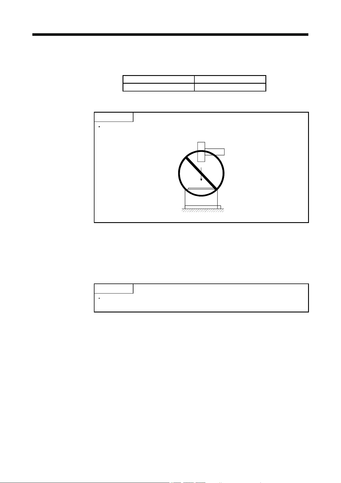
Do not get on or put heavy load on the equipment.
The servo amplifier and direct drive motor must be installed in the specified direction.
Leave specified clearances between the servo amplifier and cabinet inside walls or other equipment.
Otherwise, it may cause a malfunction.
Do not install or operate the servo amplifier and direct drive motor which has been damaged or has any
parts missing.
Do not block intake and exhaust areas of the servo amplifier. Otherwise, it may cause a malfunction.
Do not drop or strike servo amplifier or direct drive motor. Isolate from all impact loads.
Securely attach the direct drive motor to the machine. If you attach it insecurely, the direct drive motor may
come off during operation.
Measure a direct drive motor, and check the motor vibration level. A great vibration may cause the early
damage of a bearing, encoder, and brake. The great vibration may also cause the poor connector
connection or bolt looseness.
For the gain adjustment at the equipment startup, check the torque waveform and the speed waveform by
using a measurement device, and then check that no vibration occurs. If the vibration occurs due to high
gain, the vibration may cause the early damage of the direct drive motor.
Take safety measures, e.g. provide covers, to prevent accidental access to the rotor of the direct drive
motor during operation.
Never hit the rotor of the direct drive motor, especially when coupling the direct drive motor to the machine.
Otherwise, the encoder may malfunction.
A - 3
Page 5
CAUTION
Do not subject the rotor of the direct drive motor to more than the permissible load. Otherwise, the rotor
may break.
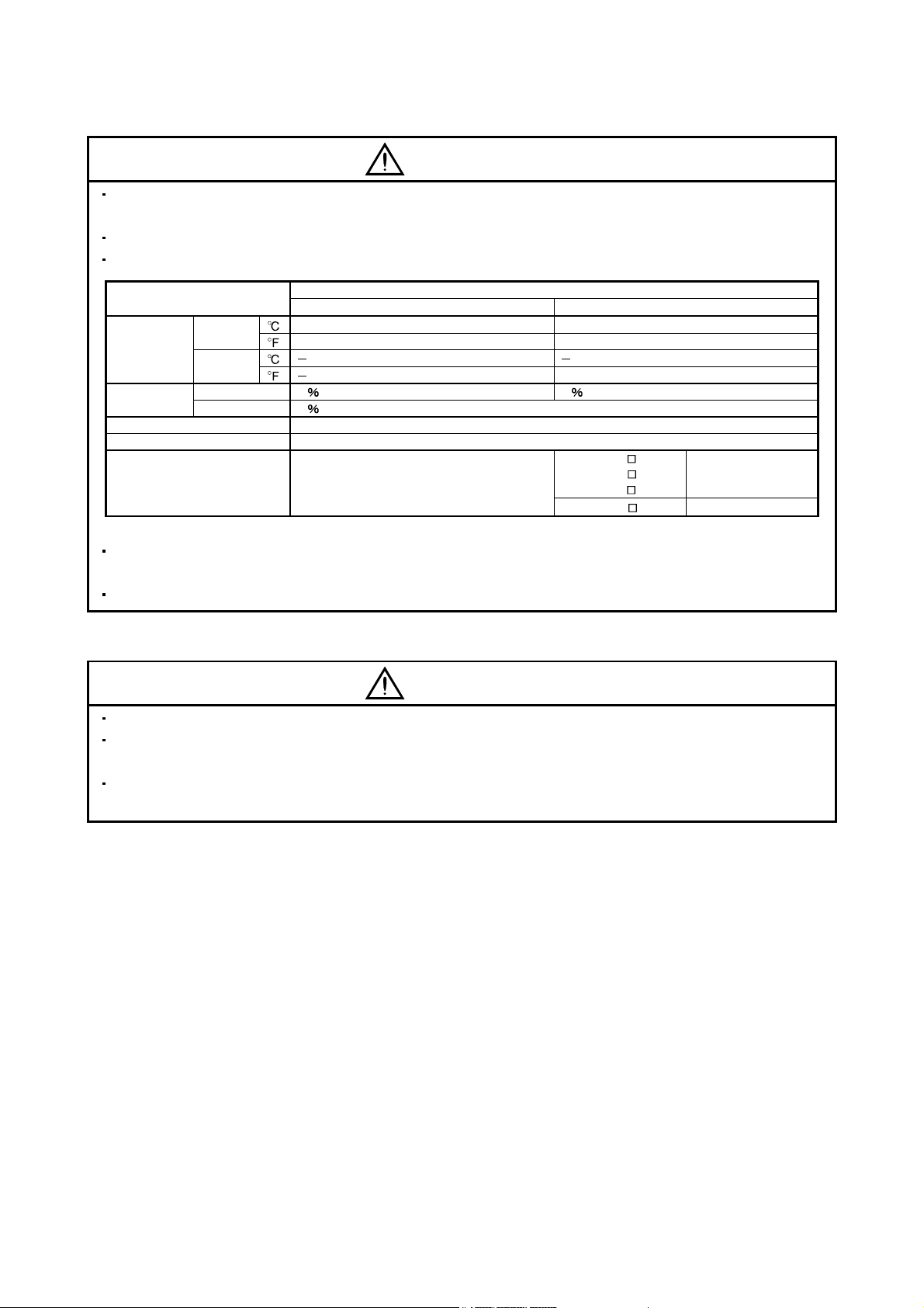
When the equipment has been stored for an extended period of time, contact your local sales office.
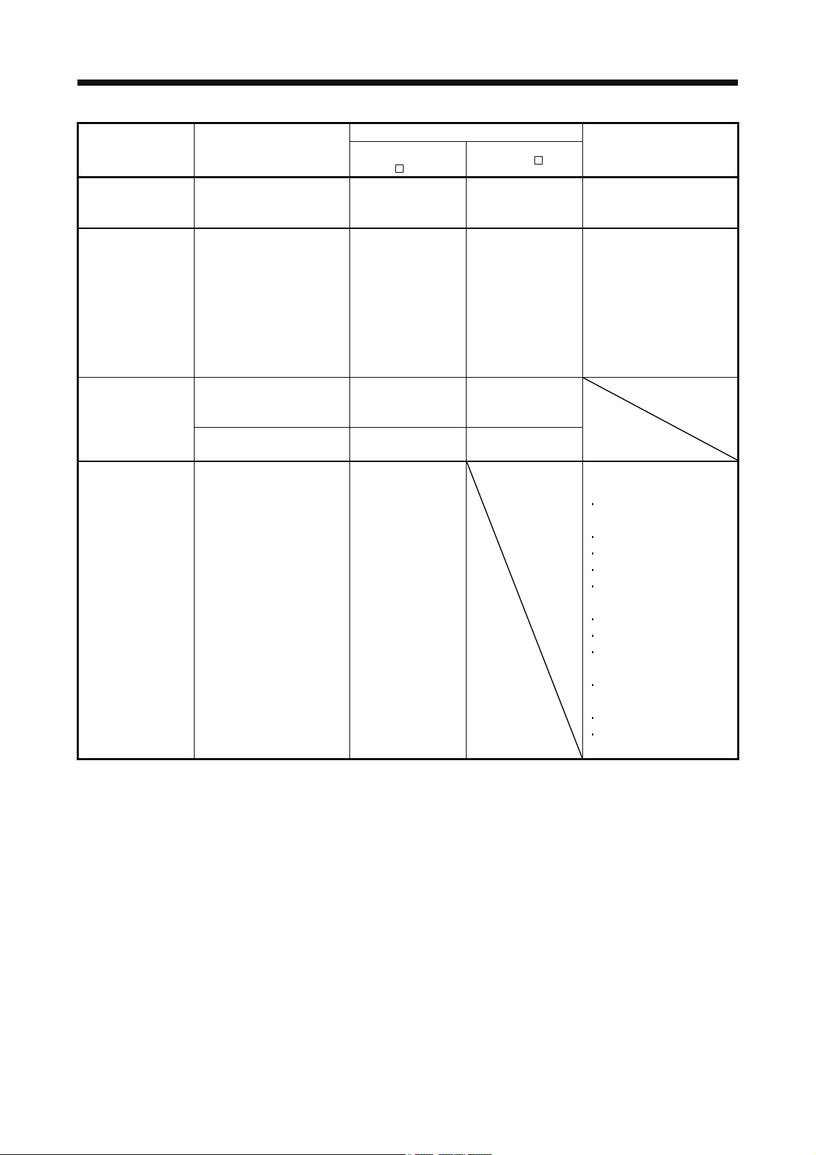
When you keep or use it, please fulfill the following environment.
Environment
[] 0 to 55 (non-freezing) 0 to 40 (non-freezing)
Ambient
temperature
[] 20 to 65 (non-freezing) 15 to 70 (non-freezing)
Ambient
Operation 90 RH or less (non-condensing) 80 RH or less (non-condensing)
humidity
Ambience Indoors (no direct sunlight) Free from corrosive gas, flammable gas, oil mist, dust and dirt
Altitude Max. 1000m above sea level
Vibration resistance
When treating the servo amplifier and direct drive motor be careful about the edged parts such as the
corners of the servo amplifier and direct drive motor.
The servo amplifier must be installed in the metal cabinet.
(2) Wiring
Item
Operation
Storage
Storage 90
[ ] 32 to 131 (non-freezing) 32 to 104 (non-freezing)
[ ] 4 to 149 (non-freezing) 5 to 158 (non-freezing)
Servo amplifier Direct drive motor
RH or less (non-condensing)
2
at 10 to 55Hz
5.9 m/s
(directions of X, Y and Z axes)
TM-RFM C20
TM-RFM
TM-RFM
TM-RFM
E20
G20
J10 X, Y: 24.5 m/s2
X, Y: 49 m/s
2
CAUTION
Wire the equipment correctly and securely. Otherwise, the direct drive motor may operate unexpectedly.
Do not install a power capacitor, surge killer or radio noise filter (FR-BIF option) between the direct drive
motor and servo amplifier.
To avoid a malfunction, connect the wires to the correct phase terminals (U, V, and W) of the servo
amplifier and direct drive motor.
A - 4
Page 6
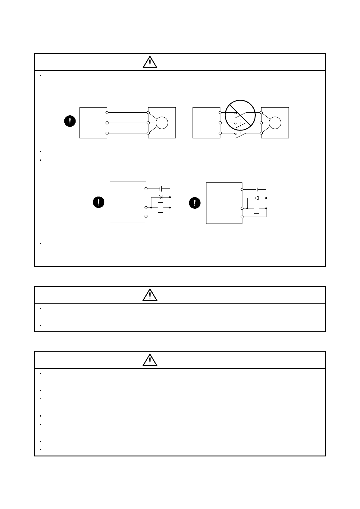
CAUTION
Connect the servo amplifier power supply output (U, V, and W) to the direct drive motor power supply input
(U, V, and W) directly. Do not let a magnetic contactor, etc. intervene. Otherwise, it may cause a
malfunction.
Servo amplifier
U
V
W
Direct drive motor
U
V
M
W
Servo amplifier Direct drive motor
U
V
W
U
V
M
W
Do not connect AC power directly to the direct drive motor. Otherwise, it may cause a malfunction.
The surge absorbing diode installed on the DC relay for control output should be fitted in the specified
direction. Otherwise, the emergency stop and other protective circuits may not operate.
Servo amplifier
DOCOM
Control output
signal
DICOM
For sink output interface
24VDC
RA
Servo amplifier
24VDC
DOCOM
Control output
signal
DICOM
For source output interface
RA
When the cable is not tightened enough to the terminal block (connector), the cable or terminal block
(connector) may generate heat because of the poor contact. Be sure to tighten the cable with specified
torque.
(3) Test run adjustment
CAUTION
Before operation, check the parameter settings. Improper settings may cause some machines to perform
unexpected operation.
The parameter settings must not be changed excessively. Operation will be instable.
(4) Usage
CAUTION
Provide an external emergency stop circuit to ensure that operation can be stopped and power switched
off immediately.
Any person who is involved in disassembly and repair should be fully competent to do the work.
Before resetting an alarm, make sure that the run signal of the servo amplifier is off to prevent an accident.
A sudden restart is made if an alarm is reset with the run signal on.
Do not modify the equipment.
Use a noise filter, etc. to minimize the influence of electromagnetic interference.
Electromagnetic interference may be given to electronic equipment used near the servo amplifier.
Burning or breaking a servo amplifier may cause a toxic gas. Do not burn or break a servo amplifier.
Use the servo amplifier with the specified direct drive motor.
A - 5
Page 7
(5) Corrective actions
CAUTION
When it is assumed that a hazardous condition may take place at the occur due to a power failure or a
product fault, use a direct drive motor with an external brake mechanism for the purpose of prevention.
When any alarm has occurred, eliminate its cause, ensure safety, and deactivate the alarm before
restarting operation.
Design the machine in order to avoid sudden restarting in case of after an instantaneous power failure.
(6) Maintenance, inspection and parts replacement
CAUTION
With age, the electrolytic capacitor of the servo amplifier will deteriorate. To prevent a secondary accident
due to a fault, it is recommended to replace the electrolytic capacitor every 10 years when used in general
environment.
Please contact your local sales office.
(7) Storage
CAUTION
Note the following points when storing the direct drive motor for an extended period of time (guideline: three
or more months).
Always store the direct drive motor indoors in a clean and dry place.
If it is stored in a dusty or damp place, make adequate provision, e.g. cover the whole product.
If the insulation resistance of the winding decreases, reexamine the storage method.
Though the direct drive motor is rust-proofed before shipment using paint or rust prevention oil, rust may
be produced depending on the storage conditions or storage period.
If the direct drive motor is to be stored for longer than six months, apply rust prevention oil again especially
to the machined surfaces of the rotor, etc.
Before using the product after storage for an extended period of time, hand-turn the direct drive motor rotor
(output shaft) to confirm that nothing is wrong with the direct drive motor.
When the equipment has been stored for an extended period of time, contact your local sales office.
(8) General instruction
To illustrate details, the equipment in the diagrams of this Specifications and Instruction Manual may have
been drawn without covers and safety guards. When the equipment is operated, the covers and safety
guards must be installed as specified. Operation must be performed in accordance with this Specifications
and Instruction Manual.
A - 6
Page 8

DISPOSAL OF WASTE
Please dispose a servo amplifier, battery (primary battery) and other options according to your local laws and
regulations.
EEP-ROM life
The number of write times to the EEP-ROM, which stores parameter settings, etc., is limited to 100,000. If the
total number of the following operations exceeds 100,000, the servo amplifier may fail when the EEP-ROM
reaches the end of its useful life.
Write to the EEP-ROM due to parameter setting changes
Write to the EEP-ROM due to device changes
Precautions for Choosing the Products
Mitsubishi will not be held liable for damage caused by factors found not to be the cause of Mitsubishi;
machine damage or lost profits caused by faults in the Mitsubishi products; damage, secondary damage,
accident compensation caused by special factors unpredictable by Mitsubishi; damages to products other
than Mitsubishi products; and to other duties.
COMPLIANCE WITH THE CE MARKING
Refer to Appendix 5 for the compliance with CE marking.
<<About the manuals>>
This Instruction Manual and the following manuals are required if you use this direct drive servo for the first
time. Always purchase them and use the direct drive servo safely.
A - 7
Page 9

Relevant manuals
Manual name Manual No.
MELSERVO-J3 Series Instructions and Cautions for Safe Use of AC Servos IB(NA)0300077
MELSERVO-J3 Series MR-J3- B Servo Amplifier Instruction Manual SH(NA)030051
This Instruction Manual describes the functions unique to the SSCNET
Therefore, when using the MR-J3-
B-RJ080W, refer to the SSCNET Interface MR-J3- B Servo
Interface Direct Drive Servo.
Amplifier Instruction Manual as well. However, the following items are not described in this Instruction
Manual. For details of these items, refer to the MR-J3-
Item MR-J3- B Servo Amplifier Instruction Manual
INSTALLATION CHAPTER 2
STARTUP CHAPTER 4
GENERAL GAIN ADJUSTMENT CHAPTER 6
SPECIAL ADJUSTMENT FUNCTIONS CHAPTER 7
OPTIONS AND AUXILIARY EQUIPMENT CHAPTER 11
B Servo Amplifier Instruction Manual.
<<Wiring>>
Wires mentioned in this instruction manual are selected based on the ambient temperature of 40
(104 ).
A - 8
Page 10

CONTENTS
1. FUNCTIONS AND CONFIGURATION 1 - 1 to 1 -12
1.1 Summary .................................................................................................................................................. 1 - 1
1.2 Servo amplifier standard specifications................................................................................................... 1 - 3
1.3 Function list .............................................................................................................................................. 1 - 4
1.4 Model code definition ............................................................................................................................... 1 - 5
1.5 Combinations of servo amplifiers and direct drive motor........................................................................ 1 - 5
1.6 Parts identification .................................................................................................................................... 1 - 6
1.7 Configuration including auxiliary equipment............................................................................................ 1 - 9
2. DIRECT DRIVE MOTOR 2 - 1 to 2 -34
2.1 Rating plate .............................................................................................................................................. 2 - 1
2.2 Parts identification .................................................................................................................................... 2 - 1
2.3 Installation ................................................................................................................................................2 - 2
2.3.1 Equipment configuration ................................................................................................................... 2 - 3
2.3.2 Installation orientation ....................................................................................................................... 2 - 4
2.3.3 Load remove precautions ................................................................................................................. 2 - 4
2.3.4 Permissible load for the rotor ............................................................................................................ 2 - 4
2.3.5 Protection from oil and water ............................................................................................................ 2 - 5
2.3.6 Inspection ..........................................................................................................................................2 - 6
2.3.7 Life ..................................................................................................................................................... 2 - 6
2.3.8 Machine accuracies .......................................................................................................................... 2 - 7
2.3.9 Flange surface size ........................................................................................................................... 2 - 7
2.4 Connectors used for direct drive motor wiring ........................................................................................ 2 - 8
2.4.1 Selection of connectors..................................................................................................................... 2 - 8
2.4.2 Wiring connectors (Connector configurations A
2.4.3 Connector outline drawings ............................................................................................................. 2 -11
2.5 TM-RFM series direct drive motor .......................................................................................................... 2 -15
2.5.1 Model code definition .......................................................................................................................2 -15
2.5.2 Specification list ................................................................................................................................ 2 -16
2.5.3 Torque characteristic........................................................................................................................ 2 -19
2.5.4 Outline dimension drawings............................................................................................................. 2 -20
2.5.5 Connection of servo amplifier and direct drive motor ..................................................................... 2 -32
B C D E F) .............................................. 2 - 9
3. SIGNALS AND WIRING 3 - 1 to 3 -12
3.1 Precautions for this chapter .....................................................................................................................3 - 2
3.2 Input power supply circuit ........................................................................................................................ 3 - 2
3.2.1 Selection example of wires ............................................................................................................... 3 - 3
3.2.2 Connection example ......................................................................................................................... 3 - 4
3.3 I/O signal connection example ................................................................................................................ 3 - 7
3.4 Connector and signal arrangements ....................................................................................................... 3 - 9
3.5 Internal connection diagram ................................................................................................................... 3 -10
3.5.1 Incremental system .......................................................................................................................... 3 -10
3.5.2 Absolute position detection system .................................................................................................3 -11
1
Page 11
4. OPERATION AND FUNCTIONS 4 - 1 to 4 -18
4.1 Startup ...................................................................................................................................................... 4 - 1
4.2 Magnetic pole detection ........................................................................................................................... 4 - 2
4.2.1 Preparation for the magnetic pole detection .................................................................................... 4 - 2
4.2.2 Driving when magnetic pole is detected........................................................................................... 4 - 3
4.2.3 Magnetic pole detection method setting........................................................................................... 4 - 6
4.2.4 Setting the magnetic pole detection voltage level of the position detection method ...................... 4 - 6
4.2.5 Magnetic pole detection method using MR Configurator................................................................. 4 - 8
4.3 Operation from the controller .................................................................................................................. 4 -10
4.3.1 Operation method............................................................................................................................. 4 -10
4.3.2 Servo system controller setting........................................................................................................ 4 -11
4.4 Servo control error detection function .................................................................................................... 4 -16
5. PARAMETERS 5 - 1 to 5 -12
5.1 Parameter write inhibit (Parameter No.PA19)......................................................................................... 5 - 1
5.2 Basic setting parameters (No.PA
5.2.1 Parameter list .................................................................................................................................... 5 - 2
5.2.2 List of details...................................................................................................................................... 5 - 3
5.3 Gain/Filter parameters (No.PB
5.3.1 Parameter list .................................................................................................................................... 5 - 5
5.4 Extension setting parameters (No.PC
5.4.1 Parameter list .................................................................................................................................... 5 - 6
5.5 I/O setting parameters (No.PD
5.5.1 Parameter list .................................................................................................................................... 5 - 7
5.6 Special setting parameters (No.PS
5.6.1 Parameter list .................................................................................................................................... 5 - 8
5.6.2 List of details...................................................................................................................................... 5 - 9
).................................................................................................... 5 - 2
) ....................................................................................................... 5 - 5
) ............................................................................................ 5 - 6
) ....................................................................................................... 5 - 7
) ................................................................................................ 5 - 8
6. TROUBLESHOOTING 6 - 1 to 6 - 8
6.1 Alarms and warning list ............................................................................................................................ 6 - 1
6.2 Remedies for alarms ................................................................................................................................ 6 - 2
6.3 Remedies for warnings ............................................................................................................................ 6 - 6
7. SERVO AMPLIFIER OUTLINE DRAWINGS 7 - 1 to 7 - 6
8. CHARACTERISTICS 8 - 1 to 8 - 4
8.1 Overload protection characteristics .........................................................................................................8 - 1
8.2 Dynamic brake characteristics................................................................................................................. 8 - 3
8.2.1 Dynamic brake operation .................................................................................................................. 8 - 3
8.2.2 The dynamic brake at the load inertia moment ratio........................................................................8 - 4
9. OPTIONS FOR DIRECT DRIVE SERVO 9 - 1 to 9 -12
9.1 Cable/connector sets ...............................................................................................................................9 - 1
2
Page 12

9.1.1 Combinations of cable and connector set ........................................................................................9 - 2
9.1.2 Encoder connector set ......................................................................................................................9 - 4
9.2 Absolute position storage unit MR-BTAS01........................................................................................... 9 -10
APPENDIX App.- 1 to App.- 8
App. 1 Parameter list..................................................................................................................................App.- 1
App. 2 Signal layout recording paper ........................................................................................................App.- 3
App. 3 Handling of AC servo amplifier batteries for the United Nations Recommendations on the
Transport of Dangerous Goods ....................................................................................................App.- 3
App. 4 Symbol for the new EU Battery Directive ......................................................................................App.- 5
App. 5 Compliance with the CE marking...................................................................................................App.- 6
3
Page 13

MEMO
4
Page 14

1. FUNCTIONS AND CONFIGURATION
1. FUNCTIONS AND CONFIGURATION
1.1 Summary
To meet high-accuracy and high-efficiency requirements in areas including semiconductor and liquid crystal
related machines, and surface mount device placement machines, a system with a direct drive motor in a drive
axis has been increased. The direct drive servo system includes the following features.
(1) Performance
(a) Since load is directly coupled to the direct drive motor, gear reducer and transmission elements can be
(2) Mechanism
eliminated, offering greater rigidity and torque.
(b) The high-resolution encoder contributes to high-accuracy control.
(c) Due to the gearless structure, error caused by backlash can be eliminated, offering high-accuracy
operation and shorter settling time.
(d) Because of no reduction gear or others, the direct drive motor does not deteriorate with time.
(a) The motor's low profile design contributes to compact construction and a low center of gravity for
enhanced machine stability.
(b) The motor has an inner rotor with hollow shaft which enables cables and pipes to be passed through.
(c) Lubrication and maintenance due to abrasion is not required.
The following shows the differences between the direct drive servo and the MR-J3-
B.
1 - 1
Page 15
1. FUNCTIONS AND CONFIGURATION
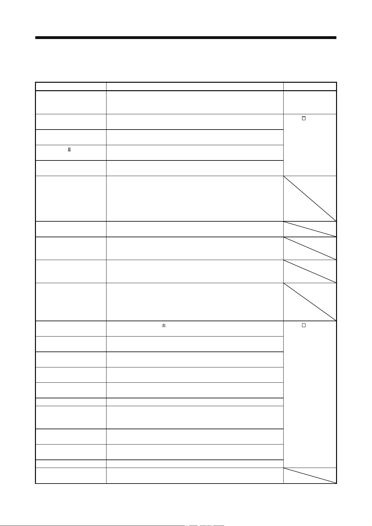
Classification Item
(MR-J3-
External I/O signal Stroke limit input signal
(FLS, RLS)
Motor pole adjustment Magnetic pole detection
operation
Absolute position
detection system
Alarm/warning Alarm/warning designed
Battery for absolute position
encoder
(MR-J3BAT)
Absolute position storage unit
(MR-BTAS01)
exclusively for the direct drive
servo
Required (when
magnetic pole is
detected)
Required Not required (adjusted
Required Required
Required Not required
Addition Alarm/warning which is added
Differences
Direct drive servo
B-RJ080W)
MR-J3-
Not required Automatically turns on in the
at shipment)
B
parameter setting.
Automatically executed at the
first servo-on after turning the
power on.
For the absolute position
detection system, the
magnetic polarity detection
can be made invalid in the
setting of parameter No.PS01.
(Refer to section 4.2.2 (2).)
or the contents is changed
Remarks
Encoder combination error
(1F)
Encoder error2 (20)
Encoder error3 (21)
Absolute position erase (25)
Initial magnetic pole
detection error (27)
Encoder counter error (2B)
Servo control error (42)
Direct drive motor overheat
(46)
Battery cable disconnection
warning (92)
Battery warning (9F)
Direct drive motor overheat
warning (E2)
1 - 2
Page 16
1. FUNCTIONS AND CONFIGURATION
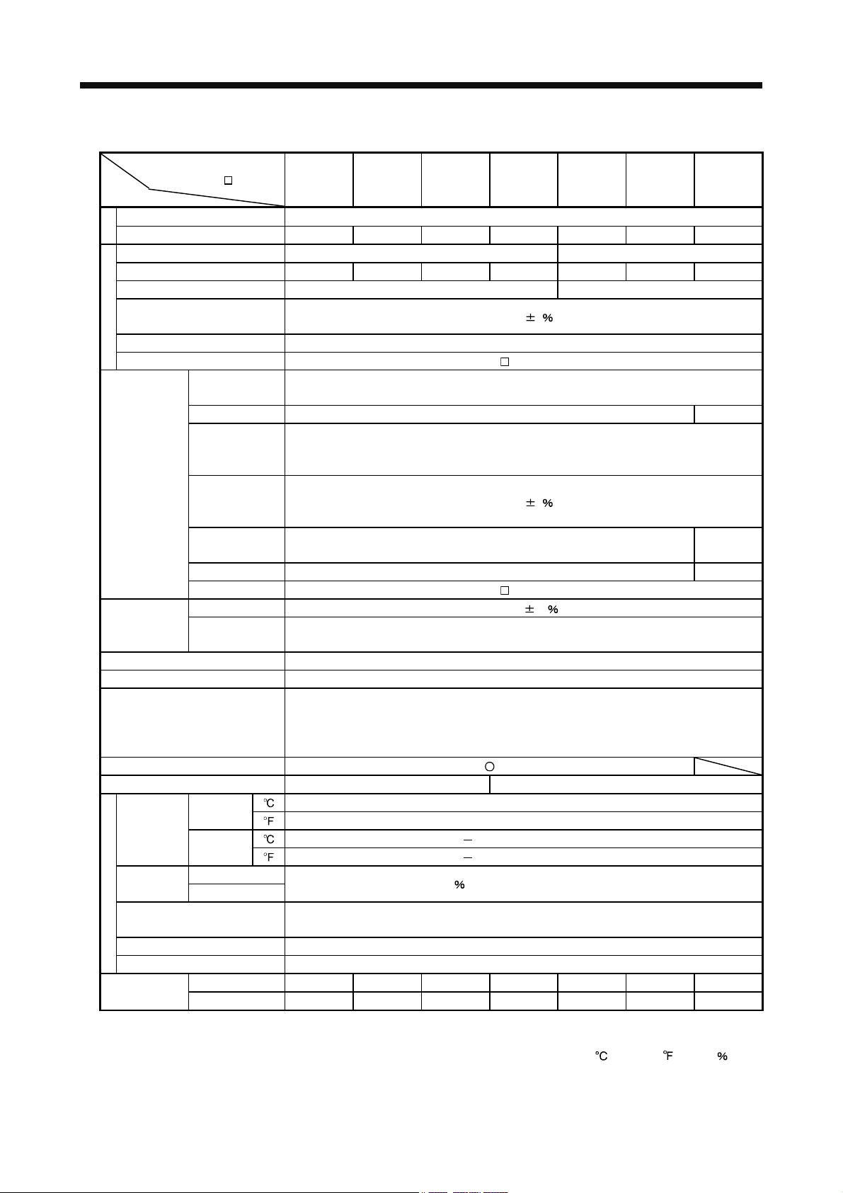
1.2 Servo amplifier standard specifications
Servo amplifier
MR-J3-
Item
Rated voltage 3-phase 170VAC
Output
Rated current [A] 1.5 2.8 3.2 5.8 6.0 17.0 28.0
Voltage/frequency 3-phase or 1-phase 200 to 230VAC, 50/60Hz 3-phase 200 to 230VAC, 50/60Hz
Rated current [A] 1.5 2.6 3.2 3.8 5.0 16.0 21.7
Permissible voltage fluctuation 3-phase or 1-phase 170 to 253VAC 3-phase 170 to 253VAC
Permissible frequency
fluctuation
Power supply capacity Refer to section 2.5.2
Main circuit power supply
Inrush current Refer to section 10.5 "MR-J3- B Servo Amplifier Instruction Manual"
Control circuit
power supply
Interface power
supply
Control system Sine-wave PWM control, current control system
Dynamic brake Built-in
Protective functions
Close mounting (Note 2)
Structure Natural-cooling, open (IP rating: IP00) Force-cooling, open (IP rating: IP00)
Ambient
temperature
humidity
Ambient
Environmental conditions
Altitude Max. 1000m above sea level
Vibration resistance 5.9m/s2 10 to 55Hz (directions of X, Y and Z axes)
Mass
Note 1. 0.15A is the value applicable when all I/O signals are used. The current capacity can be decreased by reducing the number of
I/O points.
2. When closely mounting servo amplifiers, operate them at the ambient temperatures of 0 to 45
smaller effective load ratio.
-RJ080W
Voltage,
frequency
Rated current [A] 0.2 0.3
Permissible
voltage
fluctuation
Permissible
frequency
fluctuation
Power
consumption [W]
Input 30W 45W
Inrush current Refer to section 10.5 "MR-J3-
Voltage 24VDC 10
Power supply
capacity [A]
Operation
Storage
Operation Ambient
Storage
Indoors (no direct sunlight)
[ ] (Note 2) 0 to 55 (non-freezing)
[
[ ] 20 to 65 (non-freezing)
[
[kg] 0.8 1.0 1.0 1.4 1.4 2.3 4.6
20B 40B 60B 70B 100B 350B 500B
Within
5
1-phase 200 to 230VAC, 50/60Hz
1-phase 170 to 253VAC
Within
5
30 45
B Servo Amplifier Instruction Manual"
(Note 1) 0.15
Overcurrent shut-off, regenerative overvoltage shut-off, overload shut-off (electronic thermal
relay), direct drive motor overheat protection, encoder error protection, regenerative error
protection, undervoltage, instantaneous power failure protection, overspeed protection,
excessive error protection, magnetic pole detection protection, servo control error protection
] (Note 2) 32 to 131 (non-freezing)
] 4 to 149 (non-freezing)
RH or less (non-condensing)
90
Free from corrosive gas, flammable gas, oil mist, dust and dirt
[lb] 1.8 2.2 2.2 3.1 3.1 5.1 10
(32 to 113 ) or at 75 or
1 - 3
Page 17
1. FUNCTIONS AND CONFIGURATION
1.3 Function list
The following table lists the functions of this servo. For details of the functions, refer to the reference field.
Function Description Reference
Absolute position detection
system
Gain changing function You can switch between gains during rotation and gains during stop or use an
Advanced vibration
suppression control
Adaptive filter Servo amplifier detects mechanical resonance and sets filter characteristics
Low-pass filter Suppresses high-frequency resonance which occurs as servo system response
Machine analyzer function Analyzes the frequency characteristic of the mechanical system by simply
Machine simulation Can simulate machine motions on a personal computer screen on the basis of
Gain search function Personal computer with MR Configurator changes gains automatically and
Robust disturbance
compensation
Advanced Gain search Advanced Gain search automatically searches for the optimum parameter for
Slight vibration suppression
control
Auto tuning Automatically adjusts the gain to optimum value if load applied to the direct drive
Brake unit Used when the regenerative option cannot provide enough regenerative power.
Power regenerative converter Used when the regenerative option cannot provide enough regenerative power.
Regenerative option Used when the built-in regenerative resistor of the servo amplifier does not have
Alarm history clear Alarm history is cleared.
Output signal selection
(Device settings)
Output signal (DO) forced
output
Test operation mode JOG operation positioning operation DO forced output. However, MR
Analog monitor output Servo status is output in terms of voltage in real time.
MR Configurator
(C2 or later)
Merely setting a home position once makes home position return unnecessary
at every power-on. A battery (MR-J3BAT) and an absolute position storage unit
(MR-BTAS01) are required.
input device to change gains during operation.
This function suppresses vibration at the arm end or residual vibration.
automatically to suppress mechanical vibration.
is increased.
connecting MR Configurator installed personal computer and servo amplifier.
MR Configurator is necessary for this function.
Make sure to execute the machine analyzer function after the magnetic pole
detection. If the magnetic pole detection is not executed, this function may not
operate properly.
the machine analyzer results. MR Configurator is necessary for this function.
searches for overshoot-free gains in a short time. MR Configurator is necessary
for this function.
This function provides better disturbance response in case of low response level
due to high load inertia moment ratio for the roll send axis.
MR Configurator is necessary for this function.
settle time to be short.
The gain can be adjusted by setting sequentially in accordance with wizard
screens.
MR Configurator is necessary for this function.
Suppresses vibration of 1 pulse produced at a direct drive motor stop.
motor rotor varies.
Can be used the 5kW or more servo amplifier.
Can be used the 5kW or more servo amplifier.
sufficient regenerative capability for the regenerative power generated.
The pins that output the output devices, including the malfunction (ALM) and the
dynamic brake interlock (DB), can be changed to certain pins of the CN3
connectors.
Output signal can be forced on/off independently of the servo status. Use this
function for output signal wiring check, etc.
Configurator is necessary for positioning operation.
Using a personal computer, parameter setting, test operation, status display,
etc. can be performed.
1 - 4
Chapter 9
MR-J3-
Amplifier Instruction
Manual
MR-J3-
Amplifier Instruction
Manual
B Servo
B Servo
Page 18
1. FUNCTIONS AND CONFIGURATION
1.4 Model code definition
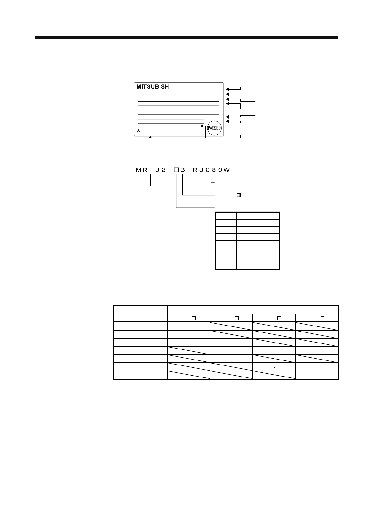
(1) Rating plate
MODEL
(2) Model
MR-J3-20B-RJ080W
200W
:
POWER
1.5A 3PH+1PH200-230V 50Hz
:
INPUT
OUTPUT
SERIAL
KCC-REI-MEK-TC300A***G51
MITSUBISHI ELECTRIC CORPORATION
MADE IN JAPAN
3PH+1PH200-230V 60Hz
2.2A 1PH200-230V 50Hz/60Hz
170V 0-360Hz 1.5A
:
A18001050
:
Series name
AC SERVO
DATE: 2012-11
The year and month of manufacture
Model
Capacity
Applicable power supply
Rated output current
Serial number
KC mark number
Country of origin
Direct drive motor compatible
SSCNET Interface
Rated output
Symbol
Rated output [kW]
20 0.2
40 0.4
60 0.6
70 0.75
100 1
350 3.5
500 5
1.5 Combinations of servo amplifiers and direct drive motor
The following table lists combinations of servo amplifiers and direct drive motors.
Servo amplifier
Direct drive motor
TM-RFM
C20 TM-RFM E20 TM-RFM G20 TM-RFM J10
MR-J3-20B-RJ080W 002
MR-J3-40B-RJ080W 004
MR-J3-60B-RJ080W 006 006
MR-J3-70B-RJ080W 012 012 040
MR-J3-100B-RJ080W 018
MR-J3-350B-RJ080W 048 072 120
MR-J3-500B-RJ080W 240
1 - 5
Page 19
1. FUNCTIONS AND CONFIGURATION
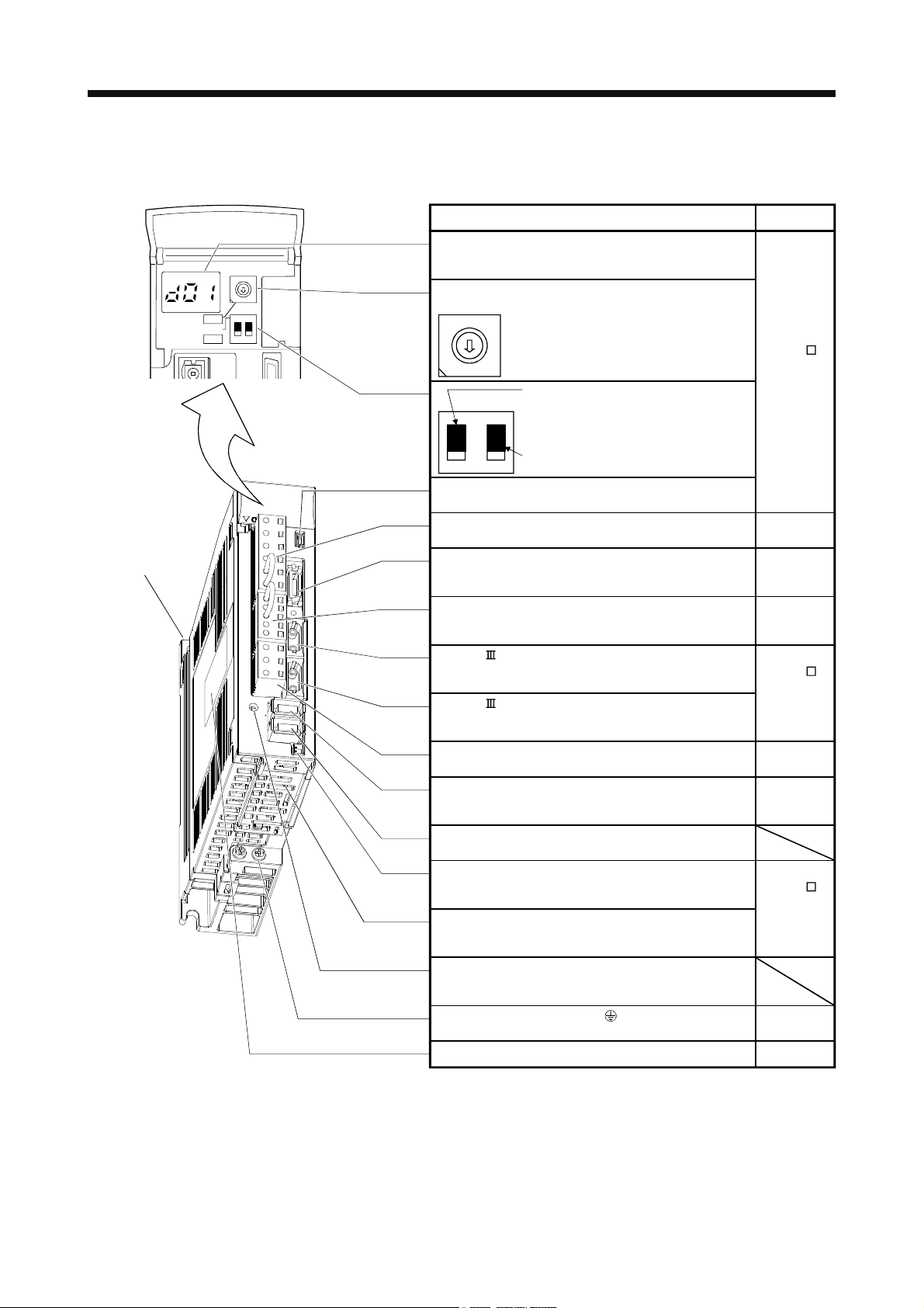
1.6 Parts identification
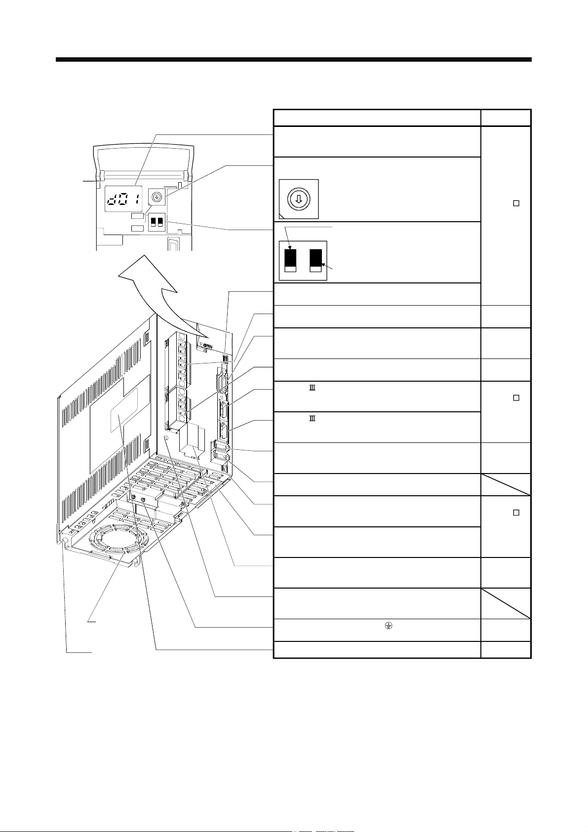
(1) MR-J3-100B-RJ080W or less
Fixed part
(2 places)
SW1
TEST
SW2
7
6
5
4
3
2
ON 4E
12
Name/Application
Detailed
explanation
Display
The 3-digit, seven-segment LED shows the servo
8
9
A
B
C
D
E
F
1
0
status and alarm number.
Rotary axis setting switch (SW1)
SW1
8
Used to set the axis No. of servo amplifier.
9
7
A
6
B
5
C
4
D
3
E
2
F
1
0
Refer to the
MR-J3- B
Servo
Amplifier
SW2
Test operation select switch (SW2-1)
Used to perform the test operation
Instruction
Manual.
mode by using MR Configurator.
For manufacturer setting (Be sure to set
to the "Down" position).
2
1
USB communication connector (CN5)
Connect the personal computer.
Main circuit power supply connector (CNP1)
Connect the input power supply.
Section 3.2
I/O signal connector (CN3)
Used to connect digital I/O signals.
Section 3.3
More over an analog monitor is output.
Control circuit connector (CNP2)
Connect the control circuit power supply/regenerative
Section 3.2
option.
SSCNET cable connector (CN1A)
Used to connect the servo system controller or the front
axis servo amplifier.
SSCNET cable connector (CN1B)
Used to connect the rear axis servo amplifier. For the final
axis, puts a cap.
Direct drive motor power output connector (CNP3)
Connect the direct drive motor.
Encoder connector (CN2)
Used to connect the direct drive motor encoder.
Refer to the
MR-J3- B
Servo
Amplifier
Instruction
Manual.
Chapter 2
Section 3.2
Chapter 2
Section 3.4
Chapter 9
Connector for manufacturer setting (CN2L)
Not used for this servo amplifier.
Battery connector (CN4)
Used to connect the battery for absolute position data
backup.
Battery holder
Install the battery MR-J3BAT.
Refer to the
MR-J3- B
Servo
Amplifier
Instruction
Manual.
Charge lamp
Lit to indicate that the main circuit is charged. While this
lamp is lit, do not reconnect the cables.
Protective earth (PE) terminal ( )
Ground terminal.
Rating plate
Section 3.2
Section 1.4
1 - 6
Page 20
1. FUNCTIONS AND CONFIGURATION
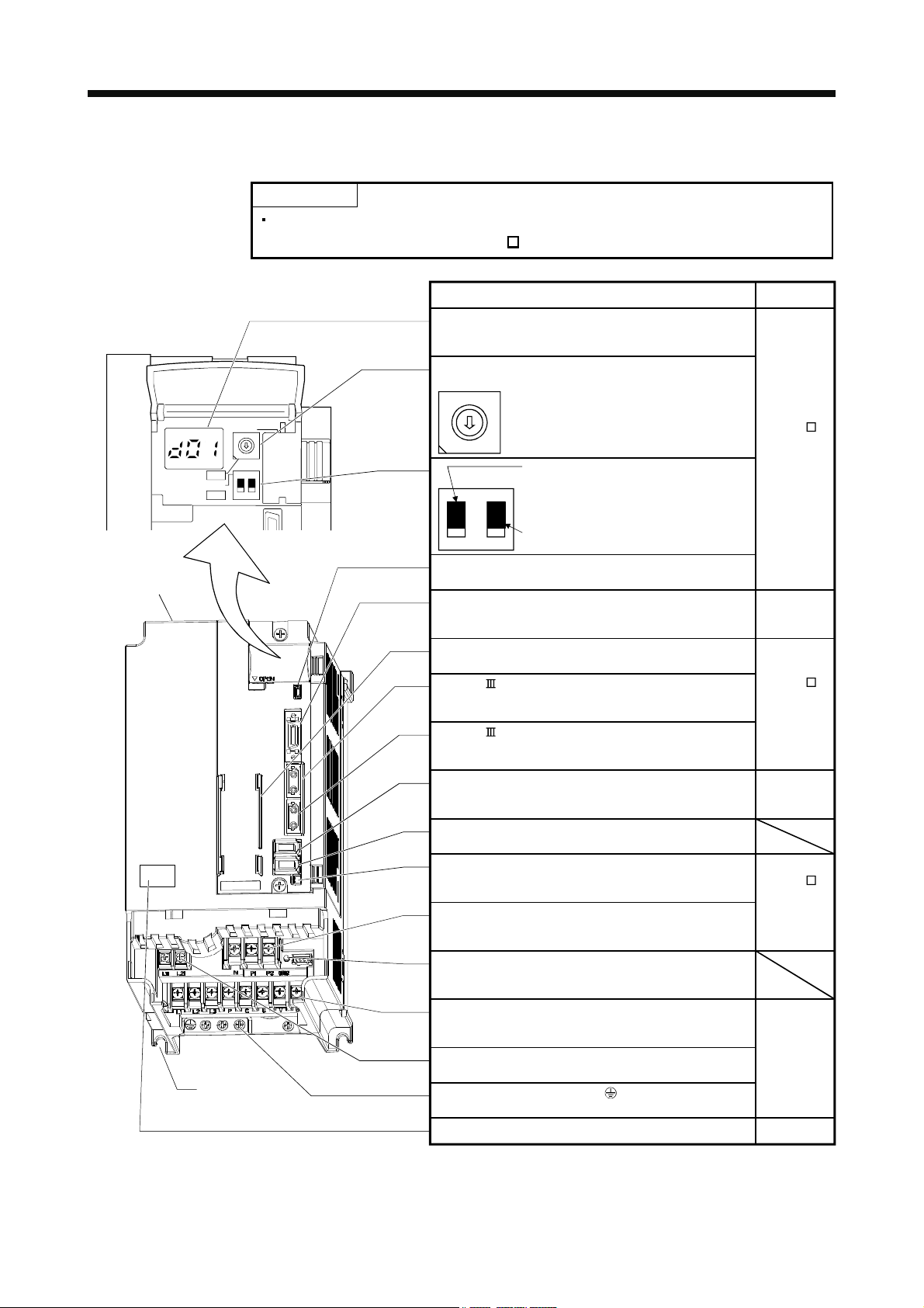
(2) MR-J3-350B-RJ080W
Cooling fan
Fixed part
(3 places)
SW1
TEST
SW2
7
6
5
4
3
2
ON 4E
12
Name/Application
Detailed
explanation
Display
The 3-digit, seven-segment LED shows the servo
status and alarm number.
Rotary axis setting switch (SW1)
SW1
8
Used to set the axis No. of servo amplifier.
9
7
8
9
A
B
C
D
E
F
1
0
A
6
B
5
C
4
D
3
E
2
F
1
0
SW2
Test operation select switch (SW2-1)
Used to perform the test operation
mode by using MR Configurator.
Refer to the
MR-J3- B
Servo
Amplifier
Instruction
Manual.
For manufacturer setting (Be sure to set
to the "Down" position).
2
1
USB communication connector (CN5)
Connect the personal computer.
Main circuit power supply connector (CNP1)
Connect the input power supply.
Section 3.2
I/O signal connector (CN3)
Used to connect digital I/O signals.
Section 3.3
More over an analog monitor is output.
Direct drive motor power output connector (CNP3)
Connect the direct drive motor.
SSCNET cable connector (CN1A)
Used to connect the servo system controller or the front
axis servo amplifier.
SSCNET cable connector (CN1B)
Used to connect the rear axis servo amplifier. For the final
axis, puts a cap.
Encoder connector (CN2)
Used to connect the direct drive motor encoder.
Chapter 2
Section 3.2
Refer to the
MR-J3- B
Servo
Amplifier
Instruction
Manual.
Chapter 2
Section 3.4
Chapter 9
Connector for manufacturer setting (CN2L)
Not used for this servo amplifier.
Battery connector (CN4)
Used to connect the battery for absolute position data
backup.
Battery holder
Install the battery MR-J3BAT.
Refer to the
MR-J3- B
Servo
Amplifier
Instruction
Manual.
Control circuit connector (CNP2)
Connect the control circuit power supply/regenerative
Section 3.2
option.
Charge lamp
Lit to indicate that the main circuit is charged. While this
lamp is lit, do not reconnect the cables.
Protective earth (PE) terminal ( )
Ground terminal.
Rating plate
Section 3.2
Section 1.4
1 - 7
Page 21
1. FUNCTIONS AND CONFIGURATION
(3) MR-J3-500B-RJ080W
POINT
The servo amplifier is shown without the front cover. For removal of the front cover,
refer to section 1.7.2 of the MR-J3-
B Servo Amplifier Instruction Manual.
Cooling fan
8
7
6
5
4
3
2
1
ON 4E
SW1
TEST
12
SW2
Fixed part
(4 places)
Name/Application
Detailed
explanation
Display
The 3-digit, seven-segment LED shows the servo
status and alarm number.
Rotary axis setting switch (SW1)
SW1
8
Used to set the axis No. of servo amplifier.
9
7
A
6
B
5
C
4
D
3
9
A
B
C
D
E
F
0
2
F
1
0
SW2
E
Test operation select switch (SW2-1)
Used to perform the test operation
Refer to the
MR-J3- B
Servo
Amplifier
Instruction
Manual.
mode by using MR Configurator.
For manufacturer setting (Be sure to set
to the "Down" position).
21
USB communication connector (CN5)
Connect the personal computer.
I/O signal connector (CN3)
Used to connect digital I/O signals.
Section 3.3
More over an analog monitor is output.
Battery holder
Install the battery MR-J3BAT.
SSCNET cable connector (CN1A)
Used to connect the servo system controller or the front
axis servo amplifier.
SSCNET cable connector (CN1B)
Used to connect the rear axis servo amplifier. For the final
Refer to the
MR-J3- B
Servo
Amplifier
Instruction
Manual.
axis, puts a cap.
Encoder connector (CN2)
Used to connect the direct drive motor encoder.
Chapter 2
Section 3.4
Chapter 9
Connector for manufacturer setting (CN2L)
Not used for this servo amplifier.
Battery connector (CN4)
Used to connect the battery for absolute position data
backup.
Power factor improving DC reactor terminal block (TE3)
Used to connect the power factor improving DC reactor.
Refer to the
MR-J3- B
Servo
Amplifier
Instruction
Manual.
Charge lamp
Lit to indicate that the main circuit is charged. While this
lamp is lit, do not reconnect the cables.
Main circuit terminal block (TE1)
Used to connect the input power supply and direct drive
motor.
Control circuit terminal block (TE2)
Section 3.2
Used to connect the control circuit power supply.
Protective earth (PE) terminal ( )
Ground terminal.
Rating plate
Section 1.4
1 - 8
Page 22
1. FUNCTIONS AND CONFIGURATION
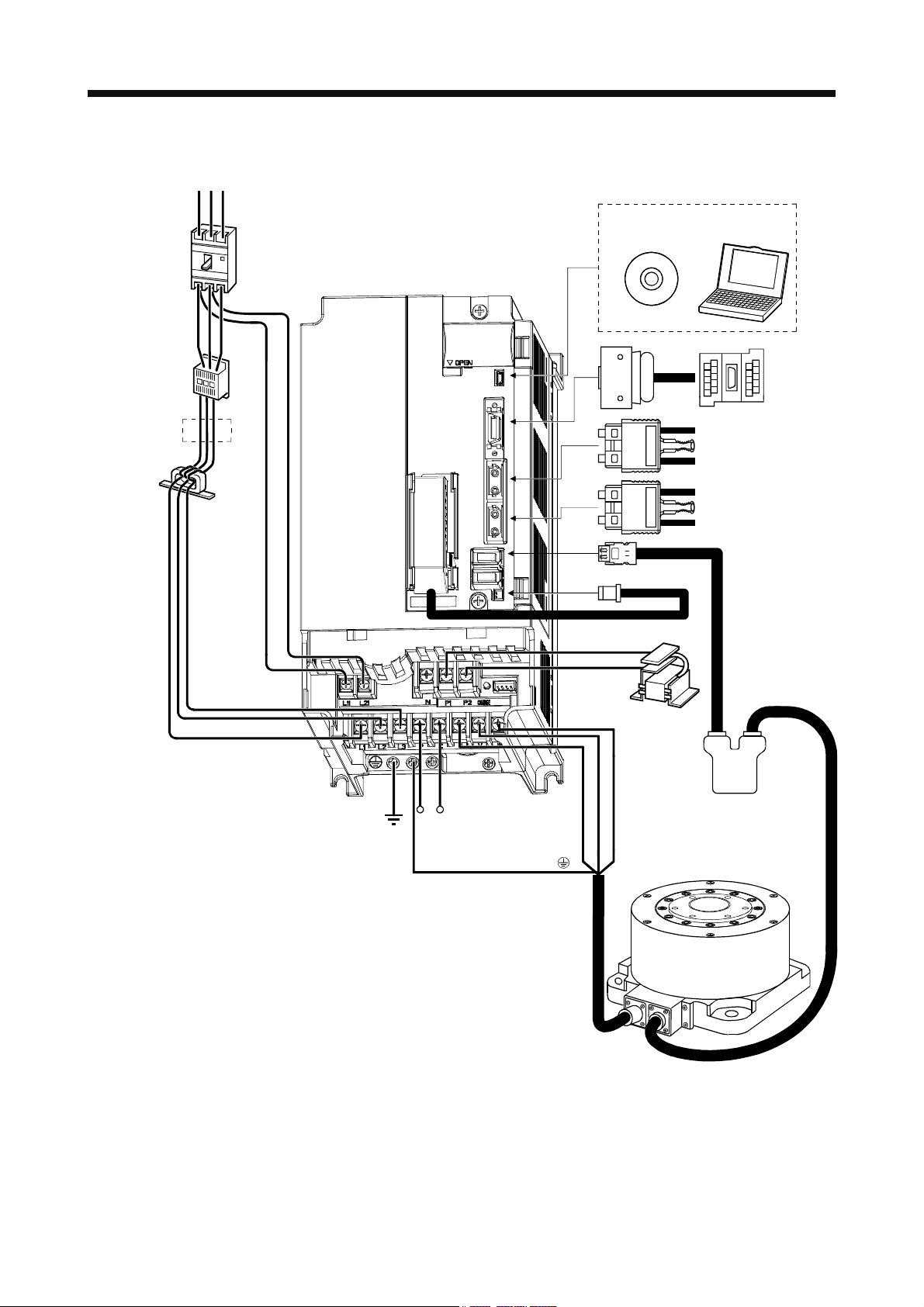
1.7 Configuration including auxiliary equipment
POINT
Equipment other than the servo amplifier and direct drive motor are optional or
recommended products.
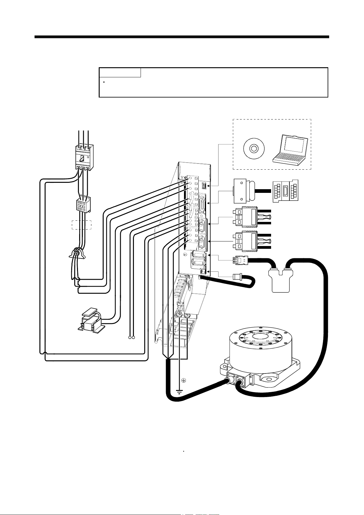
(1) MR-J3-100B-RJ080W or less
(Note 3)
Power supply
Molded-case
circuit breaker
(MCCB) or fuse
Magnetic
contactor
(MC)
(Note 2)
Line noise
filter
(FR-BSF01)
R S T
Personal
computer
Junction
terminal
block
Servo system
controller or Front axis
servo amplifier CN1B
Rear servo amplifier
CN1A or Cap
Servo amplifier
U
V
W
MR Configurator
CN5
CN3
CN1A
CN1B
CN2
1
L
L
2
L3
(Note 2)
Power factor
improving DC
reactor
(FR-BEL)
Note 1. The battery (option) and absolute position storage unit (option) are used for the absolute position detection system. (Refer to chapter
9.)
2. The power factor improving AC reactor can also be used. In this case, the power factor improving DC reactor cannot be used. When
not using the power factor improving DC reactor, short P
3. A 1-phase 200V to 230VAC power supply may be used with the servo amplifier of MR-J3-70B-RJ080W or less.
For 1-phase 200V to 230VAC, connect the power supply to L
specification.
P1
P2
PC
Regenerative option
L
11
L
21
and P2.
1
and leave L3 open. Refer to section 1.2 for the power supply
1L2
CN4
(Note 1)
Battery
MR-J3BAT
Direct drive motor
(Note 1)
Absolute
position
storage unit
MR-BTAS01
1 - 9
Page 23
1. FUNCTIONS AND CONFIGURATION
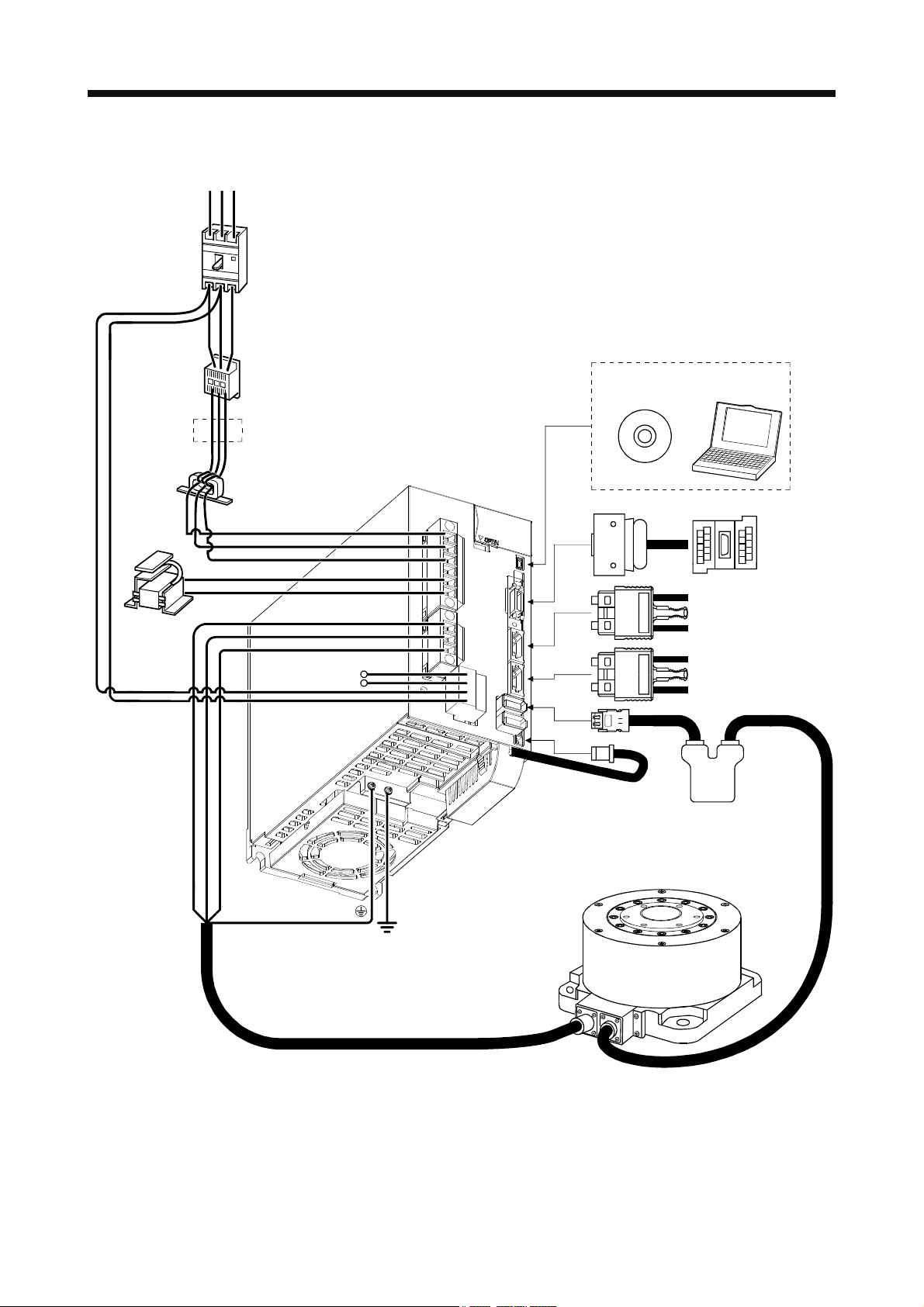
(2) MR-J3-350B-RJ080W
(Note 3)
Power supply
Molded-case
circuit breaker
(MCCB) or fuse
Magnetic
contactor
(MC)
(Note 2)
Line noise
filter
(FR-BLF)
(Note 2)
Power factor
improving DC
reactor
(FR-BEL)
L
11
L
21
R S T
P
P2
L
L
L
1
1
2
3
Regenerative option
Personal
MR Configurator
computer
CN5
Servo amplifier
CN3
Junction
terminal
block
CN1A
P
CN1B
C
Servo system
controller or Front axis
servo amplifier CN1B
Rear servo amplifier
CN1A or Cap
CN2
CN4
(Note 1)
(Note 1)
Battery
MR-J3BAT
Absolute
position
storage unit
MR-BTAS01
Direct drive motor
U
V
W
Note 1. The battery (option) and absolute position storage unit (option) are used for the absolute position detection system. (Refer to chapter
9.)
2. The power factor improving AC reactor can also be used. In this case, the power factor improving DC reactor cannot be used. When
not using the power factor improving DC reactor, short P
3. Refer to section 1.2 for the power supply specification.
and P2.
1
1 - 10
Page 24
1. FUNCTIONS AND CONFIGURATION
(3) MR-J3-500B-RJ080W
(Note 3)
Power supply
Molded-case
circuit breaker
(MCCB) or fuse
Magnetic
contactor
(MC)
(Note 2)
Line noise
filter
(FR-BLF)
R S T
Servo amplifier
(Note 1)
Battery
MR-J3BAT
CN5
CN3
CN1A
CN1B
CN2
CN4
MR Configurator
Personal
computer
Junction
terminal
block
Servo system
controller or Front axis
servo amplifier CN1B
Rear servo amplifier
CN1A or Cap
L21
L11
L
3
L2
L1
CP
Regenerative option
P1
P
2
UVW
(Note 2)
Power factor
improving DC
reactor
(FR-BEL)
Direct drive motor
(Note 1)
Absolute position
storage unit
MR-BTAS01
Note 1. The battery (option) and absolute position storage unit (option) are used for the absolute position detection system. (Refer to chapter
9.)
2. The power factor improving AC reactor can also be used. In this case, the power factor improving DC reactor cannot be used. When
not using the power factor improving DC reactor, short P
3. Refer to section 1.2 for the power supply specification.
and P2.
1
1 - 11
Page 25

1. FUNCTIONS AND CONFIGURATION
MEMO
1 - 12
Page 26
2. DIRECT DRIVE MOTOR
2. DIRECT DRIVE MOTOR
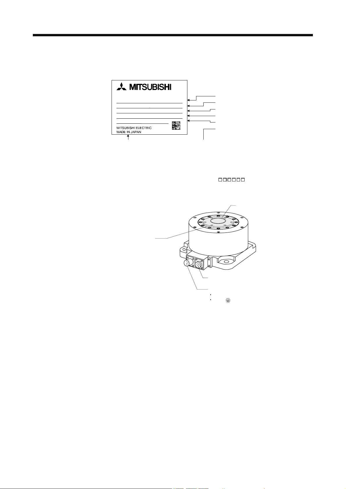
2.1 Rating plate
2.2 Parts identification
AC DIRECT DRIVE MOTOR
TM-RFM002C20
INPUT 3AC 45.7V 1.2A
TORQUE 2Nm
200r/min IP42CI.F 5.2kg
SER.No. 000000 12Y
Note. Production year and month of the direct drive motor are indicated in a serial number on the
rating plate.
The year and month of manufacture are indicated by the last two digits of the year and one
digit of the month [1 to 9, X(10), Y(11), and Z(12)].
For Nov. 2012, the Serial No. is like, "SER. No.
Z-phase mark
Model
Input power supply
Rated output
Rated speed, IP rating, Insulation class, Mass
Serial number (Note)
Country of origin
12Y".
Rotor (output shaft)
Encoder connector
Power supply connector
Power supply (U, V, and W)
Earth ( )
2 - 1
Page 27
2. DIRECT DRIVE MOTOR
2.3 Installation
WARNING
CAUTION
To prevent electric shock, ground each equipment securely.
Stacking in excess of the limited number of product packages is not allowed.
Install the equipment on incombustible material. Installing it directly or close to
combustibles will lead to a fire.
Install the equipment in a load-bearing place in accordance with this Instruction
Manual.
Do not get on or put heavy load on the equipment to prevent injury.
Use the equipment within the specified environmental condition range.
Refer to the specifications of the direct drive motor series.
Do not subject the direct drive motor to drop impact or shock loads as they are
precision equipment.
Do not install or operate the direct drive motor which has been damaged or has any
parts missing.
Do not carry the direct drive motor by holding the cables, rotor, encoder or
connector. Otherwise, a fault or injury may occur.
Securely fix the direct drive motor to the machine. If fixed insecurely, the direct drive
motor will come off during operation, leading to injury.
Measure a direct drive motor, and check the motor vibration level. A great vibration
may cause the early damage of a bearing, encoder, and brake. The great vibration
may also cause the poor connector connection or bolt looseness.
For the gain adjustment at the equipment startup, check the torque waveform and
the speed waveform by using a measurement device, and then check that no
vibration occurs. If the vibration occurs due to high gain, the vibration may cause the
early damage of the direct drive motor.
When coupling the rotor end of the direct drive motor, do not subject the rotor end to
impact, such as hammering. The encoder may become faulty.
When coupling a load to the direct drive motor, make sure to align and center the
load on the motor flange rabbet. Particularly, when the rigid coupling is used, the
slight center deviation may cause the decline of the position accuracy, and may
cause the rotor damage.
Balance the load to the extent possible. Failure to do so can cause vibration during
direct drive motor operation or damage the bearings and encoder.
Take safety measures, e.g. provide covers, to prevent accidental access to the rotor
of the direct drive motor during operation.
Do not subject the direct drive motor rotor to more than the permissible load.
Otherwise, the rotor may break, leading to injury.
When the product has been stored for an extended period of time, contact your local
sales office.
When treating the direct drive motor, be careful about the edged parts such as the
corners of the direct drive motor.
2 - 2
Page 28
2. DIRECT DRIVE MOTOR
2.3.1 Equipment configuration
This section explains the system configuration with a direct drive motor. Note the following points when using a
direct drive motor.
(1) Minimum oscillation angle
If the direct drive motor rotates repeatedly by a small angle (by 70° or less), make the direct drive motor
rotate by 90° or more at least once a day in order to keep the bearing lubricated.
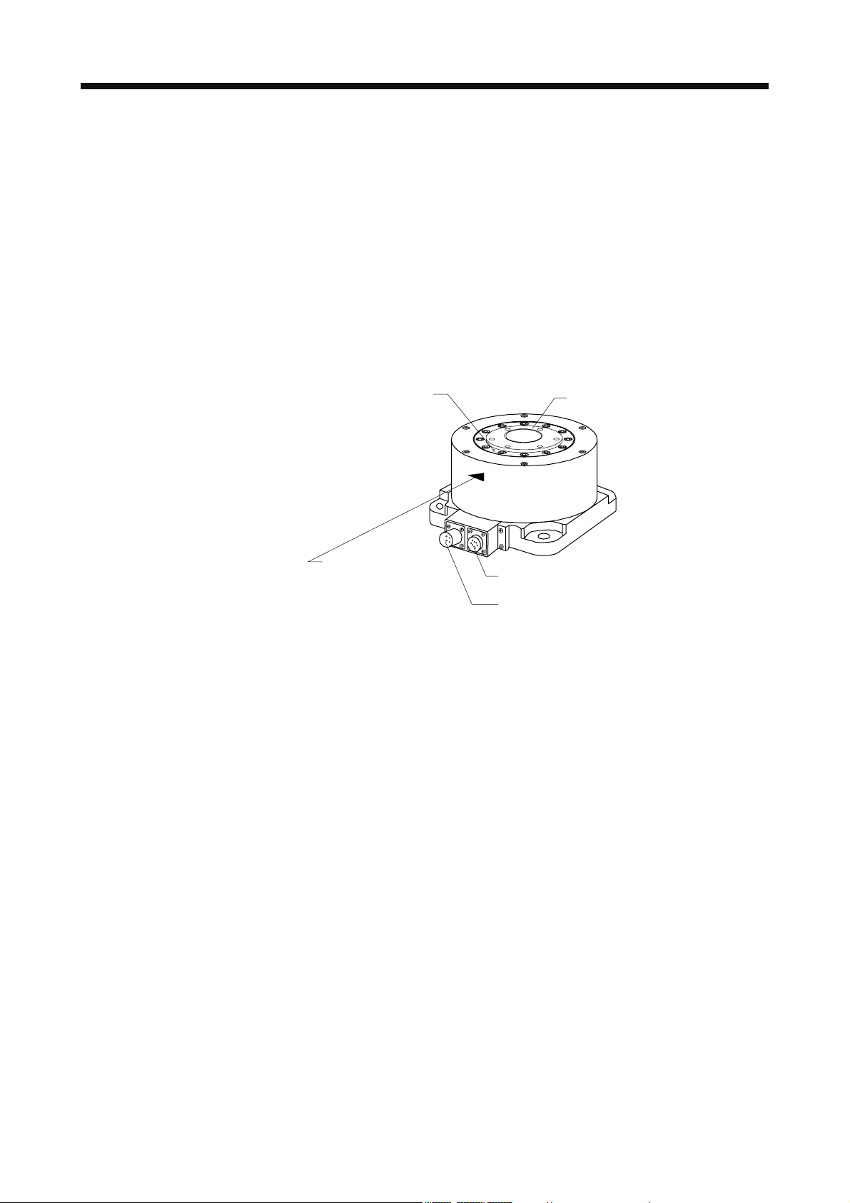
(2) Z-phase position
A Z-phase pulse turns on (Z-phase mark passing) when the Z-phase mark on the rotor end of the direct
drive motor passes over the connector area. Keep the Z-phase position visible even after the direct drive
motor is installed to a machine.
Z-phase mark
Rotor (output shaft)
Z-phase pulse turns
on when the Z-phase
mark passes over
the connector area.
Encoder connector
Power supply connector
(3) Precautions for Z-phase mark passing
After power on, the Z-phase mark of the direct drive motor must pass the connector area once. In a system
which prevents the direct drive motor from making a full rotation, install the direct drive motor in a position
where the Z-phase mark can pass over the connector area.
(4) Vertical axis (lift)
For the system where the unbalanced torque occurs, such as a vertical axis system (lift), use the motor in
the absolute position detection system. In the absolute position detection system, the absolute position is
established when the Z-phase mark passes the connector area once.
At the system startup, make the Z-phase mark pass over the connector area, and switch the servo
amplifier's power supply from off to on.
If the direct drive motor can be rotated manually, make the Z-phase mark pass over the connector area
while only the servo amplifier's control power supply is on. After that, switch the servo amplifier's power
supply from off to on.
If the direct drive motor cannot be rotated manually, detect the magnetic poles while the torque is balanced,
then run the direct drive motor in the test mode to make its Z-phase mark pass over the connector area.
After that, switch the servo amplifier's power supply from off to on.
After the Z-phase mark passes through the connector area once, magnetic pole detection is not required.
2 - 3
Page 29
2. DIRECT DRIVE MOTOR
2.3.2 Installation orientation
The following table indicates the installation orientation of the direct drive motor.
Direct drive motor series Direction of installation
TM-RFM May be installed in any direction.
2.3.3 Load remove precautions
POINT
During assembling, the rotor end must not be hammered. Doing so can cause the
encoder to fail.
(1) The orientation of the encoder on the direct drive motor cannot be changed.
(2) For installation of the direct drive motor, use spring washers, etc. and fully tighten the bolts so that they do
not become loose due to vibration.
2.3.4 Permissible load for the rotor
POINT
Because the rigid coupling may damage the rotor, make sure to align and center
the load on the rotor.
For the permissible rotor load specific to the direct drive motor, refer to section 2.5.2.
(1) When coupling a load to the direct drive motor, the load applied to the rotor must be under the permissible
load.
(2) Excess of the permissible load can cause the bearing life to reduce and the rotor to break.
(3) The load indicated in this section is static load in a single direction and does not include eccentric load.
Make eccentric load as small as possible. Not doing so can cause the direct drive motor to be damaged.
2 - 4
Page 30
2. DIRECT DRIVE MOTOR
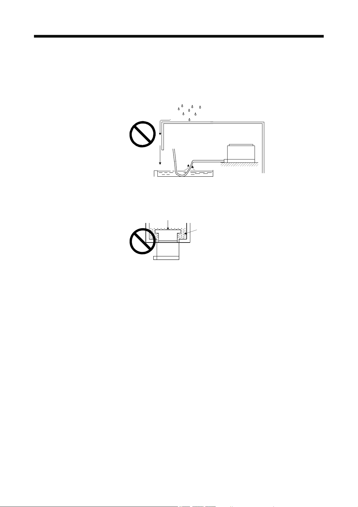
2.3.5 Protection from oil and water
Provide adequate protection to prevent foreign matter, such as oil and water from entering the direct drive motor
rotor. When installing the direct drive motor, consider the items in this section.
(1) Do not use the direct drive motor with its cable soaked in oil or water.
Cover
Direct drive motor
Oil/water pool
Capillary phenomenon
(2) Provide measures so that the direct drive motor is not exposed to oil and water entering from the machine
side, rotating table, etc.
Rotating table etc.
Lubricating oil
Direct drive motor
(3) If the direct drive motor is exposed to cutting fluid, etc., the sealant, packing, cable and others may be
affected depending on the fluid type.
(4) In the environment where the direct drive motor is exposed to oil mist, oil, water, grease and/or like, a
standard specification direct drive motor may not be usable. Provide measures to prevent dust and/or water
on the machine side.
2 - 5
Page 31

2. DIRECT DRIVE MOTOR
2.3.6 Inspection
Before starting maintenance and/or inspection, turn off the power and wait for 15
minutes or more until the charge lamp turns off. Then, confirm that the voltage
between P(
WARNING
electric shock may occur. In addition, always confirm from the front of the servo
amplifier, whether the charge lamp is off or not.
To avoid the risk of electric shock, only qualified personnel should attempt
inspections. For repair, contact your local sales office.
CAUTION
Do not disassemble and/or repair the equipment on customer side.
It is recommended to make the following checks periodically.
(a) Check the direct drive motor bearings, etc. for unusual noise.
(b) Check the cables and the like for scratches and cracks. Especially when the junction cable is movable,
perform periodic inspection according to operating conditions.
(c) Check the direct drive motor rotor (output shaft) and coupling for misalignment.
(d) Check the power supply connector and encoder connector tightening for looseness.
2.3.7 Life
) and N( ) is safe with a voltage tester and others. Otherwise, an
The following parts must be replaced periodically as listed below. If any part is found faulty, it must be replaced
immediately even when it has not yet reached the end of its life, which depends on the operating method and
environmental conditions. For parts replacement, please contact your local sales office.
Parts name Guideline of life Remarks
Bearings 20,000 to 30,000 hours
Encoder 20,000 to 30,000 hours
Absolute position
storage unit (option)
Battery MR-J3BAT
(option)
20,000 to 30,000 hours
5,000 hours
(battery life with power off)
The Guideline of Life field gives the reference time. If any fault is found
before this time is reached, the parts must be replaced.
When the direct drive motor is run at rated speed under rated load, bearings should be exchanged in 20,000 to
30,000 hours as a guideline. This differs on the operating conditions. The bearings must also be replaced if
unusual noise or vibration is found during inspection.
2 - 6
Page 32

2. DIRECT DRIVE MOTOR
2.3.8 Machine accuracies
The following table indicates the machine accuracies of the direct drive motor around the rotor (output shaft) and
mounting. (except the optional products)
Item Measured part Accuracy [mm]
Runout of flange surface about rotor (output shaft) a 0.05
Runout of fitting outer diameter of flange surface b 0.07
Runout of rotor (output shaft) c 0.04
Runout of rotor (output shaft) end d 0.02
Reference diagram
2.3.9 Flange surface size
The rated torque of the direct drive motor indicates the permissible continuous torque value that can be
generated at the specific ambient temperature (0 to 40
aluminum surface shown in this table.
Flange surface
size [mm]
002C20
400 400 20 004C20
006C20
006E20
450 450 12 012E20
018E20
012G20
550 550 12 048G20
072G20
040J10
750 750 45 120J10
240J10
). The direct drive motor is installed on the specified
Direct drive motor
TM-RFM
2 - 7
Page 33

2. DIRECT DRIVE MOTOR
2.4 Connectors used for direct drive motor wiring
POINT
The IP rating indicated is the connector's protection against ingress of dust and
water when the connector is connected to a servo amplifier, direct drive motor and
absolute position storage unit. If the IP rating of the connector, servo amplifier,
direct drive motor and absolute position storage unit vary, the overall IP rating
depends on the lowest IP rating of all components.
2.4.1 Selection of connectors
Use the connector configuration products given in the table as the connectors for connection with the direct drive
motor. Refer to section 2.4.2 for the compatible connector configuration products.
Power supply connector Encoder connector
Servo amplifier
side connector
Absolute position storage unit
Encoder side
connector
MR-BTAS01
Wiring connector
Direct drive motor
TM-RFM C20
TM-RFM E20
TM-RFM G20 Connector configuration C
TM-RFM040J10
TM-RFM120J10
TM-RFM240J10 Connector configuration E
Note. This absolute position storage unit is required for configuring absolute position detection system.
For power supply For encoder
Connector configuration B
Connector configuration D
Connector configuration A Connector configuration A Connector configuration F
Absolute position storage unit (Option) (Note)
Servo amplifier side Encoder side
2 - 8
Page 34

2. DIRECT DRIVE MOTOR
2.4.2 Wiring connectors (Connector configurations A
B C D E F)
Plug
Plug (Hirose Electric) Recommended cable (Bando Densen)
Connector
configuration
A IP67 Straight RM15WTPZK-12S JR13WCCA-8(72)
Feature
Type Plug Cord clamp Model name
clamp
Note 1. The connector to be mated.
Cord
2. Purchase from Toa Electric Industry Co. Ltd., Nagoya Branch
Plug Cable clamp
Plug (DDK) Cable clamp
Connector
configuration
B
Feature
4 to 8
IP67
EN compliant
8.3 to 11.3
General environment
(Note 1)
Type Model name
CE05-6A14S-2SD-D
Straight
Applicable wire size: AWG 22 to 16
D/MS3106B14S-2S
Applicable wire size: AWG 22 to 16
Note 1. Not comply with the EN.
2. The connector to be mated.
Cable clampPlug
20276
VSVPAWG#23×6P
KB-0492 (Note 2)
Overall
diameter of
cable
[mm]
(Reference)
8 to 12
5 to 8.3
7.9 or less
(bushing ID)
Overall
diameter of
cable
[mm]
(Reference)
8.2 RM15WTRZB-12P(72)
Model name
ACS-08RL-MS14F
(Nippon Flex)
ACS-12RL-MS14F
(Nippon Flex)
YSO14-5 to 8
(Daiwa Dengyo)
YSO14-9 to 11
(Daiwa Dengyo)
D/MS3057-6A
Direct drive motor encoder
connector or absolute
position storage unit
connector
(servo amplifier side)
(Note 1)
Direct drive motor power
supply connector (Note 2)
CE05-2A14S-2PD-D
Connector
configuration
C
Feature
EN compliant
General environment
(Note 1)
Note 1. Not comply with the EN.
2. The connector to be mated.
Plug (DDK) Cable clamp (DDK)
Type Model name
CE05-6A18-10SD-D-BSS
Straight
Applicable wire size: AWG 14 to 12
D/MS3106B18-10S
Applicable wire size: AWG 14 to 12
2 - 9
Overall
diameter of
cable
[mm]
(Reference)
8.5 to 11 CE3057-10A-2-D IP67
10.5 to 14.1 CE3057-10A-1-D
14.3 or less
(bushing ID)
Model name
D/MS3057-10A
Direct drive motor power
supply connector (Note 2)
CE05-2A18-10PD-D
Page 35

2. DIRECT DRIVE MOTOR
Connector
configuration
D
Note 1. Not comply with the EN.
2. The connector to be mated.
Feature
EN compliant
General environment
(Note 1)
Type Model name
Straight
Cable clampPlug
Plug (DDK) Cable clamp (DDK)
Overall
diameter of
cable
[mm]
(Reference)
CE05-6A22-22SD-D-BSS
Applicable wire size: AWG 10 to 8
D/MS3106B22-22S
Applicable wire size: AWG 10 to 8
Cable clampPlug
9.5 to 13 CE3057-12A-2-D IP67
12.5 to 16 CE3057-12A-1-D
15.9 or less
(bushing ID)
Model name
D/MS3057-12A
Direct drive motor power
supply connector (Note 2)
CE05-2A22-22PD-D
Plug (DDK) Cable clamp (DDK)
Connector
configuration
E
Feature
IP67
EN compliant
General environment
(Note 1)
Type Model name
CE05-6A32-17SD-D-BSS
Straight
Applicable wire size: AWG 6 to 4
D/MS3106B32-17S
Applicable wire size: AWG 6 to 4
Note 1. Not comply with the EN.
2. The connector to be mated.
Cord
Plug
Plug (Hirose Electric)
Connector
configuration
F IP67 Straight RM15WTPZ-12P(72) JR13WCCA-8(72)
Feature
Type Plug Cord clamp Model name
clamp
Note 1. The connector to be mated.
2. Purchase from Toa Electric Industry Co. Ltd., Nagoya Branch
diameter of
(Reference)
23.8 or less
(bushing ID)
20276
VSVPAWG#23×6P
KB-0492 (Note 2)
Overall
cable
[mm]
22 to 23.8 CE3057-20A-1-D
Recommended cable
(Bando Densen)
Model name
D/MS3057-20A
Overall
diameter of
cable
[mm]
(Reference)
8.2 RM15WTRZB-12S(72)
Direct drive motor power
connector (Note 2)
CE05-2A32-17PD-D
Absolute position storage
unit connector
(encoder side) (Note 1)
2 - 10
Page 36

2. DIRECT DRIVE MOTOR
2.4.3 Connector outline drawings
The connector outline drawings for wiring the direct drive motor are shown below.
(1) Hirose Electric
(a) RM15WTPZK-12S
RM15WTPZ-12P(72)
Model Connector configuration (Note)
RM15WTPZK-12S A
RM15WTPZ-12P(72) F
Note. For the connector configuration, refer to section 2.4.2.
Spanner hook gap dimension: 18
M16 0.75M19 1
[Unit: mm]
(b) JR13WCCA-8(72)
For the connector configuration, refer to the connector configuration A and F of section 2.4.2.
(2) DDK
(a) CE05-6A14S-2SD-D
For the connector configuration, refer to the connector configuration B of section 2.4.2.
36.3
Spanner hook gap dimension: 17
Positioning key
7/8-20UNEF-2B
M16 0.75
7.5
(13.2)
[Unit: mm]
[Unit: mm]
3/4-20UNEF-2A
24.0 1
5.6 0.1
8.46 0.5
2 - 11
Page 37

2. DIRECT DRIVE MOTOR
(b) CE05-6A18-10SD-D-BSS
CE05-6A22-22SD-D-BSS
CE05-6A32-17SD-D-BSS
Positioning key
[Unit: mm]
A
D
W
Model A B
CE05-6A18-10SD-D-BSS 1 1/8-18UNEF-2B 34.13 32.1 57 1-20UNEF-2A C
CE05-6A22-22SD-D-BSS 1 3/8-18UNEF-2B 40.48 38.3 61 1 3/16-18UNEF-2A D
CE05-6A32-17SD-D-BSS 2-18UNS-2B 56.33 54.2 79 1 3/4-18UNS-2A E
Note. For the connector configuration, refer to section 2.4.2.
0
C 0.8 D or less W
0.38
Connector configuration
(c) CE3057-10A-1-D
CE3057-10A-2-D
CE3057-12A-1-D
CE3057-12A-2-D
CE3057-20A-1-D
V-Thread
B
(D)
A 0.7
C
1.5
F
(Bushing inner diameter)
G 0.7
(Bushing outer diameter)
(Note)
[Unit: mm]
E
Model
CE3057-
10A-1-D
CE3057-
10A-2-D
CE3057-
12A-1-D
CE3057-
12A-2-D
CE3057-
20A-1-D
Note. For the connector configuration, refer to section 2.4.2.
Applicable
shell size
18 23.8 30.1 10.3 (41.3) 15.9
22 23.8 35 10.3 (41.3) 19
32 27.8 51.6 11.9 (43.0) 32.0 23.8 51.6 1 3/4-18UNS-2B CE3420-20-1 22.0 to 23.8 E
A B C (D) E F G V
14.1 CE3420-10-1 10.5 to 14.1
11.0
16.0 CE3420-12-1 12.5 to 16
13.0
31.7 1-20UNEF-2B
1 3/16-18UNEF-
37.3
2B
2 - 12
Enclosed
bushing type
CE3420-10-2 8.5 to 11
CE3420-12-2 9.5 to 13
Range of
applicable cables
(Reference)
Connector
configuration
(Note)
C
D
Page 38

2. DIRECT DRIVE MOTOR
(d) D/MS3106B14S-2S
D/MS3106B18-10S
D/MS3106B22-22S
D/MS3106B32-17S
W
Y or less
[Unit: mm]
L or less
J 0.12
A
Q
D/MS3106B14S-2S 7/8-20UNEF 13.49 42.88 28.57 3/4-20UNEF 8.00 30 B
D/MS3106B18-10S 1 1/8-18UNEF 18.26 52.37 34.13 1-20UNEF 9.53 42 C
D/MS3106B22-22S 1 3/8-18UNEF 18.26 56.57 40.48 1 3/16-18UNEF 9.53 50 D
D/MS3106B32-17S 2-18UNS 18.26 61.92 56.33 1 3/4-18UNS 11.13 66 E
Note. For the connector configuration, refer to section 2.4.2.
(e) D/MS3057-6A
D/MS3057-10A
D/MS3057-12A
D/MS3057-20A
V
Model name A J L Q V W Y
A 0.7
Effective thread length C
1.6
V
B 0.7
E (Bushing inner diameter)
D (Cable clamp inner diameter)
G 0.7
Connector
configuration
(Note)
[Unit: mm]
Model name Shell size A B C D E G V Bushing
D/MS3057-6A 14S 22.2 24.6 10.3 11.2 7.9 27.0 3/4-20UNEF AN3420-6 B
D/MS3057-10A 18 23.8 30.1 10.3 15.9 14.3 31.7 1-20UNEF AN3420-10 C
D/MS3057-12A 22 23.8 35.0 10.3 19.0 15.9 37.3 1 3/16-18UNEF-2A AN3420-12 D
D/MS3057-20A 32 27.8 51.6 11.9 31.7 23.8 51.6 1 3/4-18UNS AN3420-20 E
Note. For the connector configuration, refer to section 2.4.2.
Connector
configuration
(Note)
2 - 13
Page 39

2. DIRECT DRIVE MOTOR
(3) Daiwa Dengyo
[Unit: mm]
O-ring
A
across flats D
Hexagonal width
Hexagonal width
across corners D1
L
across flats D2
Hexagonal width
Hexagonal width
across corners D3
Model name
Applicable
cable OD
YSO14-5 to 8 4 to 8.3
YSO14-9 to 11 7 to 11.3
Length before
A
tightening
L
Width
across
flats
3/4-20UNEF-2B 44 23 25 26 28 B
Width
across
corners
D
D1
Width
across
flats
D2
Width
across
corners
D3
Note. For the connector configuration, refer to the section 2.4.2.
(4) Nippon Flex
(Note 1)
(Note 1) L1
A15
d
(1)
L
(2)
E
G
F
E' × F' × G'
Model name Screw C
ACS-08RLMS14F
ACS-12RLMS14F
3/4-20UNEF-2B 4.0 to 8.0 7 15.0 20 22.0 6 22 24.2 6 46 41
3/4-20UNEF-2B 8.0 to 12.0 7 15.0 24 26.4 6 36 28.6 6 46 41
Applicable
cable OD
Screw C
A d
Tightening nut Nipple body
E
Two-
face
width
F
Width
across
corners
G
Number
of
corners
E'
Twoface
width
F'
Width
across
corners
G'
Number
of
corners
L L1
Note 1. (1) Indicates the reference dimension before assembling, and (2) indicates the reference dimension after assembling.
2. For the connector configuration, refer to section 2.4.2.
Connector
configuration
(Note)
[Unit: mm]
Connector
configuration
(Note 2)
B
2 - 14
Page 40

2. DIRECT DRIVE MOTOR
2.5 TM-RFM series direct drive motor
This section provides information on the specifications and characteristics of the direct drive motor. When using
the TM-RFM series direct drive motor, always read the Safety Instructions in the beginning of this manual in
addition to this section.
2.5.1 Model code definition
The following describes what each block of a model name indicates. Note that not all the combinations of the
symbols exist.
Appearance
Series name
Rated speed
Symbol Rated speed [r/min]
10 100
20 200
Motor outer diameter (Frame dimensions)
Symbol
Rated torque
Symbol
002 2
004 4
006 6
012 12
018 18
040 40
048 48
072 72
120 120
240 240
Dimensions [mm]
C130
E180
G230
J330
Rated torque [N m]
Z-phase mark
2 - 15
Page 41

2. DIRECT DRIVE MOTOR
2.5.2 Specification list
TM-RFM series Direct drive motor
Item
Motor outer diameter (Frame dimensions) [mm] 130 180
Compatible servo amplifier model MR-J3- -RJ080W 20B 40B 60B 60B 70B 100B
Continuous running
duty (Note 1)
Rated speed (Note 1) [r/min] 200
Maximum speed [r/min] 500
Instantaneous permissible speed [r/min] 575
Maximum torque
Power rate at continuous rated torque [kW/s] 3.7 9.6 16.1 4.9 12.9 21.8
Inertia moment
Recommended ratio of load inertia moment to direct
drive motor rotor inertia moment (Note 2)
Absolute accuracy [s] 15 12.5
Power supply capacity (Note 3) [kVA] 0.25 0.38 0.53 0.46 0.81 1.3
Rated current [A] 1.3 2.1 3.1 3.1 3.8 5.9
Maximum current [A] 3.9 6.3 9.3 9.3 12 18
Speed/position detector (Note 4)
Insulation class Class F
Structure Totally enclosed, natural cooling (IP rating : IP42 (Note 5))
Environmental
conditions (Note 6)
Vibration rank (Note 8) V-10
Permissible load for the
rotor (Note 9)
Mass
Rated output [W] 42 84 126 126 251 377
Rated torque
J [ 10-4kg m2] 10.9 16.6 22.4 74 111 149
Ambient
temperature
humidity
Ambience
Altitude Max.1000m above sea level
Vibration resistance
(Note 7)
Operation
Storage
Operation 80 RH or less (non-condensing) Ambient
Storage 90
Moment load
Axial load [N] 1100 3300
[N m] 2 4 6 6 12 18
[oz
[N m] 6 12 18 18 36 54
[oz
2
[oz in2] 59.6 90.8 122 405 607 815
WK
[m/s
[N m] 22.5 70
[oz
002C20 004C20 006C20 006E20 012E20 018E20
in] 283 566 850 850 1700 2550
in] 850 1700 2550 2550 5100 7650
50 times or less
Encoder common to absolute position and incremental detection systems
(Resolution per direct drive motor 1 rotation: 1048576pulse/rev)
[ ] 0 to 40 (non-freezing)
[
] 32 to 104 (non-freezing)
[ ] 15 to 70 (non-freezing)
[
] 5 to 158 (non-freezing)
RH or less (non-condensing)
Indoors (no direct sunlight)
Free from corrosive gas, flammable gas, oil mist, dust or splash of oil or water.
2
] X: 49 Y: 49
in] 3190 9910
[kg] 5.2 6.8 8.4 11 15 18
[lb] 12 15 19 25 33 40
2 - 16
Page 42

2. DIRECT DRIVE MOTOR
TM-RFM series Direct drive motor
Item
Motor outer diameter (Frame dimensions) [mm] 230 330
Compatible servo amplifier model MR-J3- -RJ080W 70B 350B 350B 70B 350B 500B
Continuous running
duty (Note 1)
Rated speed (Note 1) [r/min] 200 100
Maximum speed [r/min] 500 200
Instantaneous permissible speed [r/min] 575 230
Maximum torque
Power rate at continuous rated torque [kW/s] 6.0 37.5 59.3 9.4 40.9 91.4
Inertia moment
Recommended ratio of load inertia moment to direct
drive motor rotor inertia moment (Note 2)
Absolute accuracy [s] 12.5 10
Power supply capacity (Note 3) [kVA] 0.71 2.7 3.8 1.2 3.4 6.6
Rated current [A] 3.4 10.9 16 4.3 11 20
Maximum current [A] 10 33 48 13 33 60
Speed/position detector (Note 4)
Insulation class Class F
Structure Totally enclosed, natural cooling (IP rating: IP42 (Note 5))
Environmental
conditions (Note 6)
Vibration rank (Note 8) V-10
Permissible load for the
rotor (Note 9)
Mass
Rated output [W] 251 1005 1508 419 1257 2513
Rated torque
J [ 10-4kg m2] 238 615 875 1694 3519 6303
Ambient
temperature
humidity
Ambience
Altitude Max.1000m above sea level
Vibration resistance
(Note 7)
Operation
Storage
Operation 80 RH or less (non-condensing) Ambient
Storage 90
Moment load
Axial load [N] 5500 16000
[N m] 12 48 72 40 120 240
[oz
[N m] 36 144 216 120 360 720
[oz
2
WK
[oz in2] 1300 3360 4780 9260 19200 34500
[m/s
[N m] 93 350
[oz
012G20 048G20 072G20 040J10 120J10 240J10
in] 1700 6800 10200 5660 17000 34000
in] 5100 20400 30600 17000 51000 102000
50 times or less
Encoder common to absolute position and incremental detection systems
(Resolution per direct drive motor 1 rotation: 1048576pulse/rev)
[ ] 0 to 40 (non-freezing)
[
] 32 to 104 (non-freezing)
[ ] 15 to 70 (non-freezing)
[
] 5 to 158 (non-freezing)
RH or less (non-condensing)
Indoors (no direct sunlight)
Free from corrosive gas, flammable gas, oil mist, dust or splash of oil or water.
2
] X: 49 Y: 49 X: 24.5 Y: 24.5
in] 13200 49600
[kg] 17 36 52 53 91 146
[lb] 38 80 115 120 205 325
2 - 17
Page 43
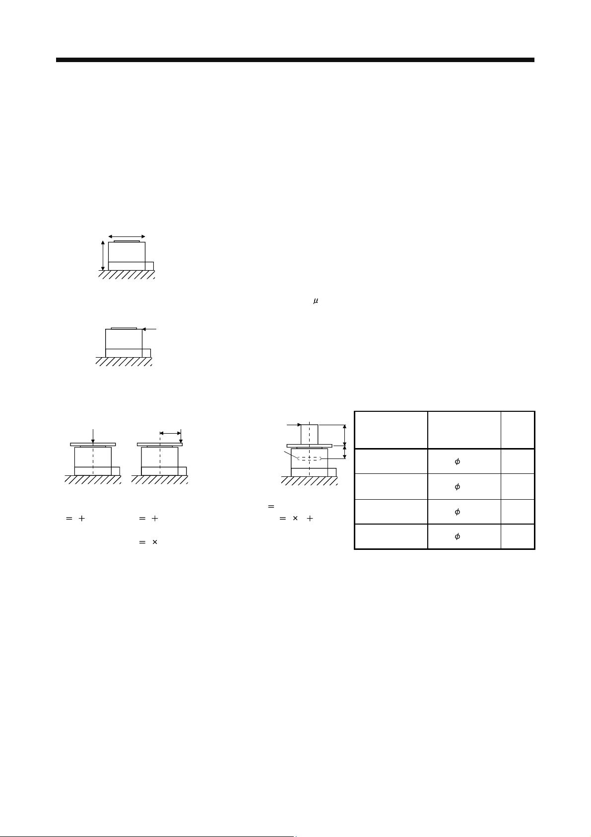
2. DIRECT DRIVE MOTOR
Note 1. When the power supply voltage drops, the output and the rated speed cannot be guaranteed.
2. If the load inertia moment ratio exceeds the indicated value, please contact your local sales office.
3. Note that the power supply equipment capacity will vary according to the power supply impedance. This value assumes that the
power factor improving AC reactor or the power factor improving DC reactor is not used.
4. Optional battery (MR-J3BAT) and absolute position storage unit (MR-BTAS01) are required for absolute position detection system.
5. Connectors and gap between rotor and stator are excluded.
6. In the environment where the direct drive motor is exposed to oil mist, oil and/or water, a standard specification direct drive motor
may not be usable. Take dustproof and waterproof measures on the machine side.
7. The vibration direction is shown in the diagram. The numeric value indicates the maximum value of the component (commonly the
bracket in the opposite direction of the direct drive motor rotor (output shaft)). Fretting of the bearing occurs easily when the motor
stops, so maintain vibration to approximately one-half of the allowable value.
Y
X
8. V-10 indicates that the amplitude of a single direct drive motor is 10 m or less. The following figure shows the direct drive motor
installation position for measurement and the measuring position.
Measuring position
9. The following is calculation examples of axial and moment loads to the rotor (output shaft). The axial and moment loads must be
maintained equal to or below the permissible value.
F (Outer force)
Axial load
F load mass
Axial load
F load mass
Moment load
F L
F (Outer force)
L
F (Outer force)
Bearing
Axial load
Moment load
load mass
F (L A)
Direct drive motor
L
A
TM-RFM002C20 to
006C20
TM-RFM006E20 to
018E20
TM-RFM012G20
to 072G20
TM-RFM040J10 to
240J10
Motor outer
diameter [mm]
(Frame dimensions)
130 19.1
180 20.2
230 24.4
330 32.5
Dimen-
sion A
[mm]
2 - 18
Page 44

2. DIRECT DRIVE MOTOR
2.5.3 Torque characteristic
POINT
When using a machine which generates unbalanced torque including a vertical
axis, use an absolute position detection system (Rrefer to section 2.3.1 (4)). It is
recommended that the unbalanced torque is 70% or less of the rated torque.
When the power supply input of the servo amplifier are 3-phase 200VAC or 1-phase 230VAC, the torque
characteristic is indicated by the heavy line. For the 1-phase 200VAC power supply, part of the torque
characteristic is indicated by the thin line. The 1-phase power supply input is applicable to the TM-RFM002C20,
TM-RFM004C20, TM-RFM006C20, TM-RFM006E20, TM-RFM012E20, TM-RFM012G20 and TM-RFM040J10.
[TM-RFM002C20]
[TM-RFM004C20]
[TM-RFM006C20]
[TM-RFM006E20]
8
6
Short-duration
4
running range
Torque [N•m]
2
Continuous
running range
0
0
100 200 300 400 500
Speed [r/min]
[TM-RFM012E20]
40
30
Short-duration
20
running range
Torque [N•m]
10
Continuous
running range
0
0 100 200 300 400 500
Speed [r/min]
16
12
Short-duration
8
running range
Torque [N•m]
4
Continuous
running range
0
0 100 200 300 400 500
Speed [r/min]
[TM-RFM018E20]
60
40
Short-duration
running range
20
Torque [N•m]
Continuous
running range
0
0 100 200 300 400 500
Speed [r/min]
24
18
Short-duration
12
running range
Torque [N•m]
6
Continuous
running range
0
0 100 200 300 400 500
Speed [r/min]
[TM-RFM012G20]
40
30
Short-duration
20
running range
Torque [N•m]
10
Continuous
running range
0
0 100 200 300 400 500
Speed [r/min]
24
18
Short-duration
12
running range
Torque [N•m]
6
Continuous
running range
0
0 100 200 300 400 500
Speed [r/min]
[TM-RFM048G20]
160
120
Short-duration
running range
80
Torque [N•m]
40
Continuous
running range
0
0 100 200 300 400 500
Speed [r/min]
[TM-RFM072G20]
240
180
Short-duration
running range
120
Torque [N•m]
60
Continuous
running range
0
0 100 200 300 400 500
Speed [r/min]
[TM-RFM040J10]
140
120
80
Short-duration
running range
Torque [N•m]
40
Continuous
running range
0
0 100 200
Speed [r/min]
[TM-RFM120J10]
400
300
Short-duration
running range
200
Torque [N•m]
100
Continuous
running range
0
0 100 200
Speed [r/min]
[TM-RFM240J10]
800
600
Short-duration
running range
400
Torque [N•m]
200
Continuous
running range
0
0 100 200
Speed [r/min]
2 - 19
Page 45

2. DIRECT DRIVE MOTOR
2.5.4 Outline dimension drawings
The actual dimensions may be 1mm to 3mm larger. Design the machine side with some allowances.
Apply general tolerances for the dimensions without tolerances.
Model
Output
[W]
TM-RFM002C20 42 10.9 (59.6) 5.2 (12)
4- 9 mounting hole
Use hexagon socket
head cap screw
Inertia moment
J [
10-4kg m2]
2
(WK
[oz in2])
1
5
0
Mass
[kg] ([lb])
[Unit: mm]
6-M5 screw depth 8
Encoder connector
RM15WTRZB-12P(72)
Arrow B
Power supply connector
CE05-2A14S-2PD-D
Caution plate
(Earth)
Power supply connector arrangement
Output shaft side
Z-phase mark
Top
Bottom
Motor plate
BC36496A
2 - 20
Page 46

2. DIRECT DRIVE MOTOR
Inertia moment
J [
10-4kg m2]
2
(WK
[oz in2])
Mass
[kg] ([lb])
Model
Output
[W]
TM-RFM004C20 84 16.6 (90.8) 6.8 (15)
[Unit: mm]
4- 9 mounting hole
Use hexagon socket
head cap screw
1
5
0
6-M5 screw depth 8
Encoder connector
RM15WTRZB-12P(72)
Arrow B
Power supply connector
CE05-2A14S-2PD-D
Caution plate
(Earth)
Power supply connector arrangement
Output shaft side
Z-phase mark
Top
Bottom
Motor plate
BC36497A
2 - 21
Page 47

2. DIRECT DRIVE MOTOR
Inertia moment
J [
10-4kg m2]
2
(WK
[oz in2])
Mass
[kg] ([lb])
Model
Output
[W]
TM-RFM006C20 126 22.4 (122) 8.4 (19)
[Unit: mm]
4- 9 mounting hole
Use hexagon socket
head cap screw
1
5
0
6-M5 screw depth 8
Encoder connector
RM15WTRZB-12P(72)
Arrow B
Power supply connector
CE05-2A14S-2PD-D
Caution plate
(Earth)
Power supply connector arrangement
Output shaft side
Z-phase mark
Top
Motor plate
BC35566B
2 - 22
Page 48

2. DIRECT DRIVE MOTOR
Inertia moment
J [
10-4kg m2]
2
(WK
[oz in2])
Mass
[kg] ([lb])
Model
Output
[W]
TM-RFM006E20 126 74.0 (405) 11 (25)
[Unit: mm]
4- 14 mounting hole
Use hexagon socket
head cap screw
2
0
5
6-M5 screw depth 8
Encoder connector
RM15WTRZB-12P(72)
Arrow B
Power supply connector
CE05-2A14S-2PD-D
Caution plate
(Earth)
Power supply connector arrangement
Output shaft side
Top
Motor plate
Z-phase mark
BC36498A
2 - 23
Page 49

2. DIRECT DRIVE MOTOR
Inertia moment
J [
10-4kg m2]
2
(WK
[oz in2])
Mass
[kg] ([lb])
Model
Output
[W]
TM-RFM012E20 251 111 (607) 15 (33)
[Unit: mm]
4- 14 mounting hole
Use hexagon socket
head cap screw
2
0
5
6-M5 screw depth 8
Encoder connector
RM15WTRZB-12P(72)
Arrow B
Power supply connector
CE05-2A14S-2PD-D
Caution plate
(Earth)
Power supply connector arrangement
Output shaft side
Top
Motor plate
Z-phase mark
BC36499A
2 - 24
Page 50

2. DIRECT DRIVE MOTOR
Inertia moment
J [
10-4kg m2]
2
(WK
[oz in2])
Mass
[kg] ([lb])
Model
Output
[W]
TM-RFM018E20 377 149 (815) 18 (40)
[Unit: mm]
4- 14 mounting hole
Use hexagon socket
head cap screw
6-M5 screw depth 8
Encoder connector
RM15WTRZB-12P(72)
Arrow B
Power supply connector
CE05-2A14S-2PD-D
Caution plate
(Earth)
Power supply connector arrangement
Output shaft side
Top
Z-phase mark
Motor plate
BC35508C
2 - 25
Page 51

2. DIRECT DRIVE MOTOR
Encoder connector
RM15WTRZB-12P(72)
2 2-M10 screw depth 19.5
Power supply connector
CE05-2A18-10PD-D
Inertia moment
J [
10-4kg m2]
2
(WK
[oz in2])
Model
Output
[W]
TM-RFM012G20 251 238 (1300) 17 (38)
4- 14 mounting hole
Use hexagon socket
head cap screw
Top
Caution plate
(Earth)
Bottom
Motor plate
Mass
[kg] ([lb])
[Unit: mm]
6-M6 screw depth 10
Z-phase mark
Power supply connector arrangement
Output shaft side
Arrow B
BC36599*
2 - 26
Page 52

2. DIRECT DRIVE MOTOR
Inertia moment
J [
10-4kg m2]
2
(WK
[oz in2])
Mass
[kg] ([lb])
Model
Output
[W]
TM-RFM048G20 1005 615 (3360) 36 (80)
[Unit: mm]
Encoder connector
RM15WTRZB-12P(72)
Arrow B
2 2-M10 screw depth 19.5
Power supply connector
CE05-2A18-10PD-D
4- 14 mounting hole
Use hexagon socket
head cap screw
Caution plate
(Earth)
Power supply connector arrangement
Output shaft side
6-M6 screw depth 10
2
6
0
Bottom
Z-phase mark
Motor plate
BC36503A
2 - 27
Page 53

2. DIRECT DRIVE MOTOR
2 2-M10 screw depth 19.5
230
Encoder connector
RM15WTRZB-12P(72)
Power supply connector
CE05-2A18-10PD-D
206h7
TM-RFM072G20 1508 875 (4780) 52 (115)
Top
Bottom
Caution plate
(Earth)
Power supply connector arrangement
Output shaft side
Model
4- 14 mounting hole
Use hexagon socket
head cap screw
Output
[W]
Inertia moment
J [
10-4kg m2]
2
(WK
[oz in2])
Motor plate
Mass
[kg] ([lb])
[Unit: mm]
6-M6 screw depth 10
TOP
Z-phase mark
Bottom
Arrow B
BC35567A
2 - 28
Page 54

2. DIRECT DRIVE MOTOR
Inertia moment
J [
10-4kg m2]
2
(WK
[oz in2])
Mass
[kg] ([lb])
Model
Output
[W]
TM-RFM040J10 838 1694 (9260) 53 (120)
[Unit: mm]
Encoder connector
RM15WTRZB-12P(72)
Arrow B
2 2-M12 screw depth 25.5
Power supply connector
CE05-2A22-22PD-D
4- 18 mounting hole
Use hexagon socket
head cap screw
Caution plate
(Earth)
Power supply connector arrangement
Output shaft side
Top
Bottom
Motor plate
6-M8 screw depth 13
Z-phase mark
BC36505*
2 - 29
Page 55

2. DIRECT DRIVE MOTOR
Inertia moment
J [
10-4kg m2]
2
(WK
[oz in2])
Mass
[kg] ([lb])
Model
Output
[W]
TM-RFM120J10 2513 3519 (19200) 91 (205)
[Unit: mm]
Encoder connector
RM15WTRZB-12P(72)
Arrow B
2 2-M12 screw depth 25.5
Power supply connector
CE05-2A22-22PD-D
4- 18 mounting hole
Use hexagon socket
head cap screw
Caution plate
(Earth)
Power supply connector arrangement
Output shaft side
Top
Bottom
Motor plate
6-M8 screw depth 13
Z-phase mark
BC36507*
2 - 30
Page 56

2. DIRECT DRIVE MOTOR
Inertia moment
J [
10-4kg m2]
2
(WK
[oz in2])
Mass
[kg] ([lb])
Model
Output
[W]
TM-RFM240J10 5027 6303 (34500) 146 (325)
[Unit: mm]
Encoder connector
RM15WTRZB-12P(72)
Arrow B
2 2-M12 screw depth 25.5
Power supply connector
CE05-2A32-17PD-D
Caution plate
(Earth)
Power supply connector arrangement
Output shaft side
4- 18 mounting hole
Use hexagon socket
head cap screw
Top
Bottom
Motor plate
6-M8 screw depth 13
Z-phase mark
BC36705*
2 - 31
Page 57

2. DIRECT DRIVE MOTOR
2.5.5 Connection of servo amplifier and direct drive motor
Any person who is involved in wiring should be fully competent to do the work.
Ground the direct drive motor securely.
Do not attempt to wire the direct drive motor until it has been installed. Otherwise, it
WARNING
CAUTION
may cause an electric shock.
The cables should not be damaged, stressed, loaded, or pinched. Otherwise, it may
cause an electric shock.
To avoid an electric shock, insulate the connection areas of the power supply
terminals.
Wire the equipment correctly and securely. Otherwise, the direct drive motor may
operate unexpectedly, resulting in injury.
Connect cables to the correct terminals. Otherwise, a burst, damage, etc. may
occur.
Ensure that polarity (+/-) is correct. Otherwise, a burst, damage, etc. may occur.
Do not install a power capacitor, surge killer, or radio noise filter (FR-BIF option) on
the power line of the direct drive motor.
Do not modify the equipment.
Connect the servo amplifier power output (U, V, and W) to the direct drive motor
power input (U, V, and W) directly. Do not let a magnetic contactor, etc. intervene.
Otherwise, it may cause a malfunction.
Servo amplifier Servo amplifier Direct drive motorDirect drive motor
U
V
W
U
V
W
M
U
V
W
U
V
M
W
2 - 32
Page 58

2. DIRECT DRIVE MOTOR
(1) Connection instructions
To avoid a malfunction, connect the power supply phases (U, V, and W) of the servo
CAUTION
This section explains the connection of the direct drive motor power (U, V, and W). Use of the optional
connector is recommended for connection between the servo amplifier and direct drive motor. Refer to chapter 9
for details of the options.
For grounding, connect the grounding lead wire from the direct drive motor to the protective earth (PE) terminal
of the servo amplifier, and then connect the wire from the servo amplifier to the ground via the protective earth of
the cabinet. Do not connect the wire directly to the protective earth of the cabinet.
amplifier and the direct drive motor correctly.
Do not connect AC power supply directly to the direct drive motor. Otherwise, it may
cause a malfunction.
POINT
Refer to chapter 9 for the encoder cable.
Cabinet
Servo
amplifier
PE terminal
Note. The number of PE terminals of the servo amplifier differs depending on the amplifier
type.
(2) Direct drive motor power cable wiring diagram
Fabricate a cable as shown below.
Refer to section 3.2.1 for the wires used for the cable.
U
V
W
(Note)
Direct drive motor
30m or less
Direct drive motorServo amplifier
U
M
V
W
2 - 33
Page 59

2. DIRECT DRIVE MOTOR
MEMO
2 - 34
Page 60

3. SIGNALS AND WIRING
3. SIGNALS AND WIRING
Any person who is involved in wiring should be fully competent to do the work.
Before wiring, turn off the power and wait for 15 minutes or more until the charge
lamp turns off. Then, confirm that the voltage between P(
a voltage tester and others. Otherwise, an electric shock may occur. In addition,
always confirm from the front of the servo amplifier whether the charge lamp is off
WARNING
or not.
Ground the servo amplifier and the direct drive motor securely.
Do not attempt to wire the servo amplifier and direct drive motor until they have
been installed. Otherwise, it may cause an electric shock.
The cables should not be damaged, stressed excessively, loaded heavily, or
pinched. Otherwise, it may cause an electric shock.
To avoid an electric shock, insulate the connections of the power supply terminals.
Wire the equipment correctly and securely. Otherwise, the direct drive motor may
operate unexpected, resulting in injury.
Connect cables to correct terminals to prevent a burst, fault, etc.
Ensure that polarity ( , ) is correct. Otherwise, a burst, damage, etc. may occur.
The surge absorbing diode installed on the DC output signal relay must be wired in
the specified direction. Otherwise, the forced stop (EM1) and other protective
circuits may not operate.
) and N( ) is safe with
CAUTION
Servo amplifier
DOCOM
Control output
signal
DICOM
For sink output interface
24VDC
RA
Servo amplifier
24VDC
DOCOM
Control output
signal
DICOM
For source output interface
RA
Electromagnetic interference may be given to electronic equipment used near the
servo amplifier. Use a noise filter, etc. to minimize the influence of electromagnetic
interference.
Do not install a power capacitor, surge killer or radio noise filter (FR-BIF option) with
the power line of the direct drive motor.
When using the regenerative resistor, switch power off with the alarm signal.
Otherwise, a transistor fault or the like may overheat the regenerative resistor,
causing a fire.
Do not modify the equipment.
Connect the servo amplifier power supply output (U, V, and W) to the direct drive
motor power supply input (U, V, and W) directly. Do not let a magnetic contactor,
etc. intervene. Otherwise, it may cause a malfunction.
Servo amplifier
U
V
W
Direct drive motor
U
V
M
W
Servo amplifier Direct drive motor
U
V
W
U
V
M
W
3 - 1
Page 61

3. SIGNALS AND WIRING
3.1 Precautions for this chapter
The following items are not described in this chapter. Since these descriptions are the same as those of MRJ3-
B Servo Amplifier, refer to the MR-J3- B Servo Amplifier Instruction Manual.
Item MR-J3- B Servo Amplifier Instruction Manual
Explanation of power supply system Section 3.3
Signal (device) explanations Section 3.5
Alarm occurrence timing chart Section 3.6
Interfaces Section 3.7 (excluding the internal connection diagram)
Treatment of cable shield external conductor Section 3.8
SSCNET cable connection Section 3.9
Grounding Section 3.12
Control axis selection Section 3.13
3.2 Input power supply circuit
Always connect a magnetic contactor between the power supply and the main
circuit power supply (L
to be able to shut down the power supply on the side of the servo amplifier’s power
supply. If a magnetic contactor is not connected, continuous flow of a large current
may cause a fire when the servo amplifier malfunctions.
CAUTION
Use malfunction (ALM) to switch main circuit power supply off. Otherwise, a
regenerative transistor fault or the like may overheat the regenerative resistor,
causing a fire.
Check the model and input the correct voltage for the power supply of the servo
amplifier. When a voltage, which exceeds the maximum input voltage of the servo
amplifier specifications, is input, the servo amplifier malfunctions.
POINT
Even if alarm has occurred, do not switch off the control circuit power supply.
When the control circuit power supply has been switched off, optical module does
not operate, and optical transmission of SSCNET
Therefore, the servo amplifier on the rear axis displays "AA" at the indicator and
turns into base circuit shut-off. The direct drive motor stops with starting dynamic
brake.
For details of each signal, refer to section 3.3 of the MR-J3- B Servo Amplifier
Instruction Manual.
Connect the direct drive motor power terminal (U, V, and W) to the direct drive
motor power input terminal (U, V, and W) directly. Do not let a magnetic contactor,
etc. intervene. Otherwise, it may cause a malfunction.
Servo amplifier
U
V
W
Wire the power supply/main circuit as shown below so that power is shut off and the servo-on command turned
off as soon as an alarm occurs, a servo forced stop is made valid, or a controller forced stop is made valid. A
molded-case circuit breaker (MCCB) must be used with the input cables of the main circuit power supply.
, L2, and L3) of the servo amplifier, and configure the wiring
1
communication is interrupted.
Direct drive motor
U
V
M
W
Servo amplifier Direct drive motor
U
V
W
U
V
M
W
3 - 2
Page 62

3. SIGNALS AND WIRING
3.2.1 Selection example of wires
POINT
Selection condition of wire size is as follows.
Construction condition: One wire is constructed in the air
Wire length: 30m or less
(1) When using the 600V Grade heat-resistant polyvinyl chloride insulated wire (HIV wire)
Selection example of wire size when using HIV wires is indicated below.
Table 3.1 Wire size selection example 2 (HIV wire)
Servo amplifier
MR-J3-20B-RJ080W
MR-J3-40B-RJ080W
MR-J3-60B-RJ080W 2(AWG14) 1.25(AW G16)
MR-J3-70B-RJ080W
MR-J3-100B-RJ080W
MR-J3-350B-RJ080W 3.5(AWG12) 3.5(AWG12)
MR-J3-500B-RJ080W (Note 2) 5.5(AWG10): a 1.25(AWG16): b 5.5(AWG10): a 2(AWG14): c
Note 1. Alphabets in the table indicate crimping tools. For crimping terminals and applicable tools, refer to (3) in this
section.
2. When connecting to the terminal block, be sure to use the screws which are provided with the terminal block.
3. Wires are selected based on the highest rated current among combining direct drive motors.
(2) Selection example of crimping terminals
Selection example of crimping terminals for the servo amplifier terminal box when using the wires
mentioned in table 3.1 in this section is indicated below.
Servo amplifier side crimping terminals
Symbol Applicable tool
a FVD5.5-4 YNT-1210S
b FVD2-M3
c FVD2-4
Note. Some crimping terminals may not be mounted depending on the size. Make sure to
use the recommended ones or equivalent ones.
Wires [mm2] (Note 1, 3)
1 L2 L3 L11 L21 UV W PC
L
(Note)
Crimping terminal
1.25(AWG16)
Body
YNT-1614
Manufacturer
Japan Solderless
Terminals
2(AWG14)
3 - 3
Page 63

3. SIGNALS AND WIRING
3.2.2 Connection example
(1) For 3-phase 200 to 230VAC power supply to MR-J3-20B-RJ080W to MR-J3-100B-RJ080W
MR-J3-350B-RJ080W
3-phase
200 to
230VAC
MCCB
(Note 3)
Malfunct
RA1
ion
Controller
forced stop
(Note 6)
Forced stop
RA2
MC (Note 8)
(Note 1)
(Note 2)
OFF
Servo amplifier
CNP1
L
1
L
2
L3
N( )
P
1
P
2
CNP2
P( )
C
D
(Note 7)
L
11
L21
ON
MC
CNP3
U
V
W
PE
CN2
MC
SK
(Note 5)
Encoder cable
Direct drive motor
U
V
W
Motor
M
Encoder
(Note 4)
Forced stop
(Note 6)
EM1
DOCOM
CN3CN3
DOCOM
DICOM
ALM
24VDC
RA1
Malfunction
(Note 4)
(Note 3)
Note 1. Always connect P1 and P2. (Factory-wired.) When using the power factor improving DC reactor, refer to chapter 11 of the MR-J3-
B Servo Amplifier Instruction Manual. Use either the power factor improving DC reactor or the power factor improving AC reactor.
2. Always connect P(
) and D. (Factory-wired.) When using the regenerative option, refer to chapter 11 of the MR-J3- B Servo
Amplifier Instruction Manual.
3. If deactivating output of malfunction (ALM) with parameter change, configure up the power supply circuit which switches off the
magnetic contactor after detection of alarm occurrence on the controller side.
4. For sink I/O interface. For source I/O interface, refer to section 3.7.3 of the MR-J3-
B Servo Amplifier Instruction Manual.
5. For details of connection of the servo amplifier and direct drive motor, refer to section 2.5.5.
6. Configure the circuit to shut down the main circuit power supply simultaneously with the turn off of forced stop (EM1) using the
external sequence.
7. This connector detects speed, position and temperature of the direct drive motor. (Refer to chapter 9.)
8. Be sure to use a magnetic contactor with an operation delay time of 80ms or less. The operation delay time is the time interval
between current being applied to the magnetic coil until closure of contacts.
3 - 4
Page 64

3. SIGNALS AND WIRING
(2) For 1-phase 200 to 230VAC power supply to MR-J3-20B-RJ080W to MR-J3-70B-RJ080W
1-phase
200 to
230VAC
(Note 4)
MCCB
Forced stop
(Note 6)
(Note 3)
Malfunction
RA1
Controller
forced stop
(Note 1)
(Note 2)
(Note 6)
Forced stop
RA2
MC (Note 8)
OFF
ON
MC
Servo amplifier
CNP1
L
1
CNP3
L2
L
3
N
W
P1
P2
PE
CNP2
P
C
D
(Note 7)
CN2
L11
L21
CN3 CN3
EM1
DOCOM
DOCOM
DICOM
ALM
U
V
MC
SK
(Note 5)
Encoder cable
24VDC
RA1
Direct drive motor
U
Motor
V
W
M
Encoder
Malfunction
(Note 3)
(Note 4)
Note 1. Always connect P1 and P2. (Factory-wired.) When using the power factor improving DC reactor, refer to chapter 11 of the MR-J3-
B Servo Amplifier Instruction Manual. Use either the power factor improving DC reactor or the power factor improving AC reactor.
2. Always connect P and D. (Factory-wired.) When using the regenerative option, refer to chapter 11 of the MR-J3-
B Servo
Amplifier Instruction Manual.
3. If deactivating output of malfunction (ALM) with parameter change, configure up the power supply circuit which switches off the
magnetic contactor after detection of alarm occurrence on the controller side.
4. For sink I/O interface. For source I/O interface, refer to section 3.7.3 of the MR-J3-
B Servo Amplifier Instruction Manual.
5. For details of connection of the servo amplifier and direct drive motor, refer to section 2.5.5.
6. Configure the circuit to shut down the main circuit power supply simultaneously with the turn off of forced stop (EM1) using the
external sequence.
7. This connector detects speed, position and temperature of the direct drive motor. (Refer to chapter 9.)
8. Be sure to use a magnetic contactor with an operation delay time of 80ms or less. The operation delay time is the time interval
between current being applied to the magnetic coil until closure of contacts.
3 - 5
Page 65

3. SIGNALS AND WIRING
(3) MR-J3-500B-RJ080W
3-phase
200 to
230VAC
MCCB
(Note 3)
Malfunction
RA1
(Note 6)
Forced stop
RA2
Controller
forced stop
MC (Note 8)
(Note 2)
(Note 1)
OFF
Servo amplifier
TE1
L1
Built-in
L
2
regenerative
resistor
L3
P
C
TE2
L
11
L
21
TE3
N
(Note 7)
P1
P
2
ON
MC
U
V
W
PE
CN2
MC
SK
(Note 5)
Encoder cable
Direct drive motor
U
Motor
V
M
W
Encoder
(Note 4)
Forced stop
(Note 6)
CN3 CN3
EM1
DOCOM
DOCOM
DICOM
ALM
24VDC
RA1
Malfunction
(Note 4)
(Note 3)
Note 1. Always connect P1 and P2. (Factory-wired.) When using the power factor improving DC reactor, refer to chapter 11 of the MR-J3-
B Servo Amplifier Instruction Manual. Use either the power factor improving DC reactor or the power factor improving AC reactor.
2. When using the regenerative option, refer to chapter 11 of the MR-J3-
B Servo Amplifier Instruction Manual.
3. If deactivating output of malfunction (ALM) with parameter change, configure up the power supply circuit which switches off the
magnetic contactor after detection of alarm occurrence on the controller side.
4. For sink I/O interface. For source I/O interface, refer to section 3.7.3 of the MR-J3-
B Servo Amplifier Instruction Manual.
5. For details of connection of the servo amplifier and direct drive motor, refer to section 2.5.5.
6. Configure the circuit to shut down the main circuit power supply simultaneously with the turn off of forced stop (EM1) using the
external sequence.
7. This connector detects speed, position and temperature of the direct drive motor. (Refer to chapter 9.)
8. Be sure to use a magnetic contactor with an operation delay time of 80ms or less. The operation delay time is the time interval
between current being applied to the magnetic coil until closure of contacts.
3 - 6
Page 66

3. SIGNALS AND WIRING
3.3 I/O signal connection example
POINT
For details of each signal, refer to chapter 3 of the MR-J3- B Servo Amplifier
Instruction Manual.
(Note 14)
(Note 15)
(Note 5)
MR Configurator
Upper stroke limit (FLS)
Lower stroke limit (RLS)
Proximity dog (DOG)
(Note 3, 4) Forced stop
Personal
computer
DICOM
DOCOM
EM1
DI1
DI2
DI3
Servo am plifier
(Note 12)
(Note 12)
CN3
20
12
19
5
3
2
CN5
CN3
13 MBR
9INP
15 ALM
10
6LA
16 LAR
7LB
17 LBR
8LZ
18 LZR
11 LG
DICOM
10m or less 10m or less
(Note 10)
24VDC
USB cable
MR-J3USBCBL3M
(option)
(Note 2)
RA1
RA2
RA3
Magnetic brake interlock
In-position
Malfunction
Encoder A-phase pulse
(differential line driver)
Encoder B-phase pulse
(differential line driver)
Encoder Z-phase pulse
(differential line driver)
Control common
(Note 16)
(Note 11)
(Note 13, 14)
Servo system
controller
(Note 6)
SSCNET cable
(option)
(Note 6)
SSCNET cable
(option)
4
1LG
14 MO2
Plate
CN1A
SW1
SW2
CN1B
MR-J3-B-RJ080W
(2 axis)
SW1
CN1A
SW2
CN1B
MR-J3-B-RJ080W
(3 axis)
SW1
CN1A
SW2
CN1B
21
21
21
MO1
SD
2m or less
(Note 8)
(Note 1)
(Note 7)
(Note 8)
(Note 7)
(Note 8)
Analog monitor 1
Analog monitor 2
(Note 9)
Cap
MR-J3-B-RJ080W
(n axis)
CN1A
CN1B
SW1
SW2
21
(Note 7)
(Note 8)
3 - 7
Page 67

3. SIGNALS AND WIRING
Note 1 To prevent an electric shock, always connect the protective earth (PE) terminal ( ) of the servo amplifier to the protective earth
(PE) of the cabinet.
2. Connect the diode in the correct direction. If it is connected reversely, the servo amplifier will be faulty and will not output signals,
disabling the forced stop (EM1) and other protective circuits.
3. If the controller does not have an forced stop (EM1) function, always install a forced stop switch (Normally closed contact).
4. When starting operation, always turn on the forced stop (EM1). (Normally closed contact) By setting "
No.PA04 of the servo amplifier, the forced stop (EM1) can be made invalid.
5. Use MRZJW3-SETUP 221E (Software version is C2 or later). (Refer to section 11.8 of the MR-J3-
Manual)
6. Use SSCNET
cables listed in the following table.
Cable Cable model name Cable length
Standard cord inside panel MR-J3BUS M 0.15m to 3m
Standard cable outside panel MR-J3BUS M-A 5m to 20m
Long-distance cable MR-J3BUS M-B 30m to 50m
7. The wiring of the second and subsequent axis is omitted.
8. Up to 16 axes may be connected. Refer to section 3.13 of the MR-J3-
selection.
9. Make sure to put a cap on the unused CN1A
10. Supply 24VDC
The current capacity can be decreased by reducing the number of I/O points. Refer to section 3.7.2 (1) of the MR-J3-
Amplifier Instruction Manual that gives the current value necessary for the interface.
11. Malfunction (ALM) turns on in normal alarm-free condition (Normally closed contacts).
12. The pins with the same signal name are connected in the servo amplifier.
13. The signal can be changed by parameter No.PD07, PD08, PD09.
14. For sink I/O interface. For source I/O interface, refer to section 3.7.3 of the MR-J3-
15. Devices can be assigned for DI1
instruction manual. The assigned devices are for the Q173DCPU, Q172DCPU, Q170MCPU, LD77MH
QD75MH
16. Electromagnetic brake interlock (MBR) is useful when setting up an external brake system.
10 150mA current for interfaces from the outside. 150mA is the value applicable when all I/O signals are used.
DI2 DI3 with controller setting. For devices that can be assigned, refer to the controller
.
CN1B.
B Servo Amplifier Instruction Manual for setting of axis
B Servo Amplifier Instruction Manual.
1 " in the parameter
B Servo Amplifier Instruction
B Servo
,QD74MH and
3 - 8
Page 68

3. SIGNALS AND WIRING
3.4 Connector and signal arrangements
POINT
The pin configurations of the connectors are as viewed from the cable connector
wiring section.
The servo amplifier front view shown is for MR-J3-20B-RJ080W or less. For the appearances and connector
layouts of other servo amplifiers, refer to chapter 7 SERVO AMPLIFIER OUTLINE DRAWINGS.
CN5 (USB connector)
Refer to section 11.8 of the MR-J3- B
Servo Amplifier Instruction Manual.
CN3
OPEN
L1
2
L
3
L
N
1
P
2
P
P
C
D
11
L
12
L
U
V
W
CHARGE
CN4 CN2L CN2 CN1B CN1A CN3 CN5
CN1A
Connector for the
front axis of CN1A
SSCNET cable.
CN1B
Connector for the
rear axis of CN1B
SSCNET cable.
The frames of the CN2 and CN3 connectors
are connected to the PE (earth) terminal in
the servo amplifier.
2
DI1
4
MO1
6
LA
8
LZ
10
DICOM
1
LG
3
DOCOM
5
DICOM
7
LB
9
12
DI2
14
MO2
16
LAR
18
LZR
20
EM1
11
LG
13
MBR
15
ALM
17
LBR
19
DI3INP
CN2
2
LG 8
1
P5
4
MRR
3
MR
6
5
MDR
7
10
9
BAT
MD
The figures of connectors
manufactured by 3M are shown
above. When using any other
connector, refer to section 9.1.2.
3 - 9
Page 69

3. SIGNALS AND WIRING
3.5 Internal connection diagram
3.5.1 Incremental system
EM1
DI1 2
DI2 12
DI3 19
DICOM
DOCOM
VBUS
D12
D
GND
CN3
20
CN5
Forced stop
(Note 1)
(Note 2)
24VDC
USB
Servo amplifier
Approx.
5.6k
Approx.
5.6k
5
3
<Isolated>
3
5
CN3
DICOM
10
MBR
13
INP
9
ALM
15
CN3
LA
6
LAR
16
LB
7
LBR
17
LZ
8
LZR
18
CN3
4
MO1
LG1
14
MO2
11
LG
CN2
3
4MRMRR
2
P5
LG
5THM1
6THM2
1P5 9P5
RA
RA
Differential line
driver output
(35mA or less)
Analog monitor
10VDC
10VDC
(Note 4)
MR
MRR
LG
(Note 2)
Direct drive
motor
7
8
(Note 3)
10
Encoder
6THM1
11THM2
Note 1. Signal can be assigned for these pins with controller setting.
For contents of signals, refer to the instruction manual of controller.
2. For sink I/O interface. For source I/O interface, refer to section 3.7.3 of the MR-J3-
3. Speed, position and temperature of the direct drive motor are detected.
4. Fabrication of the encoder cable is required at user side. (Refer to section 9.1.2.)
3 - 10
E
B Servo Amplifier Instruction Manual.
M
Page 70

3. SIGNALS AND WIRING
3.5.2 Absolute position detection system
(Note 2)
(Note 1)
Forced stop
24VDC
USB
EM1
DI1 2
DI2 12
DI3 19
DICOM
DOCOM
VBUS
D12
D
GND
CN3
20
5
3
CN5
3
5
Approx.
5.6k
Approx.
5.6k
<Isolated>
Servo amplifier
P5
CN3
DICOM
10
MBR
13
9
INP
15
ALM
CN3
6
LA
16
LAR
7
LB
17
LBR
8
LZ
18
LZR
CN3
MO1
4
LG1
MO2
14
LG
11
CN2
3
4MRMRR
2
LG
5THM1
6THM2
1P5
9BAT
RA
RA
Analog monitor
Absolute position
strage unit (Note 4)
(Note 5) (Note 5)
MR
MRR
LG
THM1
P5 9
BAT
(Note 2)
Differential line
driver output
(35mA or less)
10VDC
10VDC
7
8
10
10
6
11THM2
11
2
MR
7
8
MRR
LG
6
THM1
THM2
9
P5
2
BAT
1
VB
MR
MRR
LG
THM1
THM2
P5
BAT
VB
Direct drive
motor
7
8
10
(Note 3)
6
Encoder
11
9
2
1
E
Note 1. Signal can be assigned for these pins with controller setting.
For contents of signals, refer to the instruction manual of controller.
2. For sink I/O interface. For source I/O interface, refer to section 3.7.3 of the MR-J3-
B Servo Amplifier Instruction Manual.
3. Speed, position and temperature of the direct drive motor are detected.
4. To configure the absolute position detection system, always connect this by combining with the MR-J3BAT battery. (Refer to
section 9.2.)
5. Fabrication of the encoder cable is required at user side. (Refer to section 9.1.2.)
M
3 - 11
Page 71

3. SIGNALS AND WIRING
MEMO
3 - 12
Page 72

4. OPERATION AND FUNCTIONS
4. OPERATION AND FUNCTIONS
4.1 Startup
Start up the direct drive servo referring to the following procedure.
Execution of installation and wiring
Incremental system
(Note 1) Execution of the magnetic pole detection (Refer to section 4.2)
Absolute position
detection system?
Z-phase pulse of the direct drive motor is turned on
by the JOG operation (Note 1 and 2)
Change to the setting not requiring the magnetic
pole detection (Refer to section 4.2.2)
Absolute position detection system
Can you manually turn
on the Z-phase pulse of the direct
Turn the servo amplifier power
supply off and on (Note 2)
drive motor?
No
Perform this procedure once at startup
Yes
Z-phase pulse of the direct drive
motor is turned on manually (Note 3)
(Note 1) Positioning operation check using the test operation mode
Positioning operation check using the controller (Refer to section 4.3)
Home position return (Refer to the manual of the controller.)
Positioning operation
Note 1. MR Configurator is used.
2. Under the absolute position detection system, always turn on the Z-phase pulse of the direct drive motor while the servo amplifier
power supply is on, then turn the servo amplifier power supply off and on. By turning off and on the power supply, the absolute
position becomes confirmed. Without this operation, the absolute position cannot be regained properly, and a warning will occur at
the controller side.
3. If the Z-phase pulse of the direct drive motor can be turned on manually, it does not have to be turned on by the magnetic pole
detection or the JOG operation.
For this operation, always connect the direct drive motor encoder and the servo amplifier and turn on only the control circuit power
supply of the servo amplifier (L
the safety.
, L21) (turn off the main circuit power supply L1, L2, and L3). Perform this operation by considering
11
4 - 1
Page 73

4. OPERATION AND FUNCTIONS
4.2 Magnetic pole detection
POINT
Magnetic pole detection is not required for the configured absolute position
detection system where the Z-phase pulse can be turned on manually.
For this operation, always connect the direct drive motor encoder and the servo
amplifier and turn on the control circuit power supply of the servo amplifier. Perform
this operation by considering the safety.
Make sure to perform the magnetic pole detection before starting the positioning operation in order to match the
positional relationship between the direct drive motor and the encoder.
Before starting up the equipment, always perform the test operation (positioning operation) of MR Configurator.
4.2.1 Preparation for the magnetic pole detection
POINT
When the test operation mode is set with the test operation select switch (SW2-1),
the SSCNET
with the test operation mode is disconnected.
For the magnetic pole detection, the test operation mode (positioning operation) of MR Configurator is used.
Turn the power of servo amplifier off and set the test operation select switch (SW2-1) as shown below. By
turning the power on, it switches to the test operation mode.
communication of the servo amplifiers following the servo amplifier
8
9
7
A
6
B
5
C
4
D
3
E
F
2
1
0
ON 4E
SW1
TEST
SW2
Up
Down
12
Set the SW2-1 to "Up"
4 - 2
Page 74

4. OPERATION AND FUNCTIONS
4.2.2 Driving when magnetic pole is detected
WARNING
CAUTION
For the following cases, the magnetic pole detection is required.
(a) When using the incremental system (Refer to (1) in this section)
(b) When using the absolute position detection system and matching with the cases indicated below (Refer
to (2) in this section)
At the system setup (at the first startup of equipment)
When the direct drive motor is replaced
When the Z-phase pulse of the direct drive motor cannot be turned on manually
When the absolute position erase (25) alarm has occurred
Note that the magnetic pole detection is automatically started simultaneously with
turning on the servo-on command.
If the magnetic pole detection is not executed properly, the direct drive motor may
run unexpectedly.
POINT
Establish the machine configuration using the stroke limits (FLS and RLS). If the
stroke limits (FLS and RLS) do not exist, it may cause the machine damage by a
collision.
At the magnetic pole detection, it is not predictable whether it moves to the forward
rotation or reverse rotation.
Setting the parameter No.PS09 (Magnetic pole detection voltage level) may cause
the occurrence of overload, overcurrent, magnetic pole detection alarm, etc.
When performing the positioning operation from the controller, set the sequence
which confirms the normal completion of magnetic pole detection and the servo-on
status, then outputs the positioning command. If outputting the positioning
command before the Ready (RD) turns on, the command may not be accepted or
the servo alarm may occur.
After the magnetic pole detection, check the accuracy of position with the test
operation (positioning operation) of MR Configurator.
The accuracy of magnetic pole detection will be improved by being operated in the
no-load condition.
4 - 3
Page 75

4. OPERATION AND FUNCTIONS
(1) For the incremental system
For the incremental system, the magnetic pole detection is required every time the power is turned on. By
turning on the servo-on command from the controller after the power-on, the magnetic pole detection is
automatically carried out. Therefore, there is no need to set the parameters (first digit of parameter No.
PS01) for executing the magnetic pole detection.
(a) Timing chart
Servo-on command
Base circuit
Ready (RD)
Note. The magnetic pole detection time indicates the operation time when the stroke limits
(FLS and RLS) is on.
ON
OFF
ON
OFF
ON
OFF
(b) Direct drive motor movement (when FLS and RLS are on)
95ms
15s or less
Magnetic pole detection time (Note)
Center of direct drive motor rotation part
FLS (Note)(Note) RLS
Servo-on position (Magnetic pole detection start position)
Magnetic pole detection complete position
10deg or less
Note. When the stroke limit (FLS and RLS) turns off during the magnetic pole detection, the
operation of magnetic pole detection is carried on to the opposite direction. When both
FLS and RLS are off, the magnetic pole detection error (27) occurs.
(c) Direct drive motor movement (when FLS and RLS is off)
When the FLS and RLS are off at the servo-on, the magnetic pole detection is carried out as follows.
RLS
Magnetic pole detection
start position
Center of direct drive motor rotation part
FLS
Servo-on position
After the machine moves to the position where the stroke
limit (FLS and RLS) is set, the magnetic pole detection
starts.
Magnetic pole detection complete position
10deg or less
4 - 4
Page 76

4. OPERATION AND FUNCTIONS
(2) For the absolute position detection system
POINT
Be sure to turn on the Z-phase pulse in JOG operation after the magnetic pole
detection.
Carry out the magnetic pole detection referring the following procedure.
(a) Set the parameter No.PS01 (Special function selection 1) to "
valid)".
Parameter No.PS01
1
1 (Magnetic pole detection always
Magnetic pole detection always valid (initial value)
(b) Execute the magnetic pole detection. (Refer to (1) (a) and (b) in this section)
(c) Change the parameter No.PS01 to "
0 (Magnetic pole detection not valid)" after the normal
completion of magnetic pole detection.
Parameter No.PS01
0
Magnetic pole detection invalid
By turning on the Z-phase pulse in JOG operation and by making the magnetic pole detection function
invalid with the parameter No.PS01 after the magnetic pole detection, the magnetic pole detection for
each power-on will be unnecessary.
4 - 5
Page 77

4. OPERATION AND FUNCTIONS
4.2.3 Magnetic pole detection method setting
Set a magnetic pole detection method to the 1st digit (method selection for the magnetic pole detection) of
parameter No.PS08.
Parameter No.PS08
Method selection for the magnetic pole detection
0: Position detection method
4: Minute position detection method
4.2.4 Setting the magnetic pole detection voltage level of the position detection method
Set the voltage level in parameter No.PS09 (Magnetic pole detection voltage level) to perform magnetic pole
detection with the position detection method. Voltage level setting is not required when detecting magnetic poles
by the minute position detection method.
(1) Guideline of parameter settings
Set the parameters referring to the following table.
Parameter No.PS09 setting value
(Indication)
Servo status
Torque at operation Small Large
Overload, overcurrent alarm
Magnetic pole detection alarm Frequently occurred
Magnetic pole detection accuracy Low High
(Less than 10 (Initial value) More than 50)
Small
Not frequently
occurred
(2) Setting procedure
(a) By carrying out the magnetic pole operation, make the setting of parameter No.PS09 (magnetic pole
detection voltage level) larger until the overload 1 (50), overload 2 (51), overload warning 1 (E1) and
overload warning 2 (EC) occur. To get a rough idea, make it lager in "5". When these alarms and
warnings occur during the magnetic pole detection by MR Configurator, the test operation of MR
Configurator is automatically completed and the servo-off status is established.
(b) Set the final setting value to approximately 70% of the value which is set at the occurrence of the
overload 1 (50), overload 2 (51), overload warning 1 (E1) and overload warning 2 (EC). However, in the
case where the initial magnetic pole detection error (27) occurs with this setting value, set the final
setting value to the value intermediate between the setting value at the occurrence of the overload 1
(50), overload 2 (51), overload warning 1 (E1), overload warning 2 (EC) and the setting value at the
occurrence of the magnetic pole detection alarm.
(c) Carry out the magnetic pole detection again with the final setting value.
Middle Large
Frequently occurred
Not frequently
occurred
4 - 6
Page 78

4. OPERATION AND FUNCTIONS
(3) Setting example
Magnetic pole detection
Parameter No.PS09 setting value
Overload and overcurrent alarm
Existence or nonexistence
30 35 40 45 65 70
Carry out the magnetic pole detection repeatedly while making
the setting value of the parameter No.PS09 larger.
An alarm has occurred
when the setting value
of the parameter
No.PS09 is set to 70.
Here, the final setting value of the parameter No.PS09 is set to 49 (the setting value at the occurrence of the
overload and overcurrent alarm
70 0.7).
4 - 7
Page 79

4. OPERATION AND FUNCTIONS
4.2.5 Magnetic pole detection method using MR Configurator
The following shows the procedure of the magnetic pole detection using MR Configurator.
(1) Magnetic pole detection using position detection method
Magnetic pole detection
After confirming that the stroke limits (FLS and RLS) and the forced stop (EM1) are on, turn the
1)
power of servo amplifier off once and then turn it on again.
2)
After switching the test operation select switch (SW2-1) of the servo amplifier to "Up", turn the power
of servo amplifier off once and then turn it on again.
3)
Set parameter No.PS08 (Special function selection 3) to " 0", and the magnetic pole detection
method to "position detection method".
Change to "Magnetic pole detection always valid" by setting the parameter No.PS01 (Special
4)
function selection 1) to " 1". (Note)
5)
Turn the power of servo amplifier off once and then turn it on again.
6)
Set the parameter No.PS09 (Magnetic detection voltage level) to "F10" (guide value) as a guide.
7)
Execute the "forward rotation" or "reverse rotation" with the "positioning operat" of the MR
Configrator test operation mode. Set the travel distance to "0" at this time.
The magnetic pole detection is carried out.
YES
Is the parameter No.PS09
(Magnetic pole detection
voltage level) the final value?
NO
Reset the alarm or turn the power
Has the magnetic pole
detection alarm (27) occurred?
YES
of servo amplifier off once, and
then turn the power on again.
NO
Have the overload alarms (50 and
51), overcurrent alarm (32) and
overload warning (E1) occurred?
YES
NO
Turn the power of servo amplifier
off once and then turn it on again.
Reset the alarm or turn the power
of servo amplifier off, and then turn
the power on again.
Raise the value of parameter
No.PS09 in five.
Set approximately 70% of the
parameter No.PS09 as the final
setting vale.
In the case where the magnetic pole
detection error (27) occurs with this
setting value, set the final setting
value to the value intermediate
between the setting value at the
occurrence of the overload alarms
(50 and 51), overcurrent alarm (32),
overload warning (E1) and the setting
value at the occurrence of the
magnetic pole detection alarm (27).
Change to "Magnetic pole detection invalid" by setting the parameter No.PS01 (Special function
8)
selection 1) to " 0". (Note)
End
Note. Parameter No.PS01 setting is unnecessary for an incremental system.
4 - 8
Page 80

4. OPERATION AND FUNCTIONS
(2) Magnetic pole detection using minute position detection method
Magnetic pole detection
1) After confirming that the stroke limits (FLS and RLS) and the forced stop (EM1) are on, turn the
power of servo amplifier off once and then turn it on again.
After switching the test operation select switch (SW2-1) of the servo amplifier to "Up", turn the power
2)
of servo amplifier off once and then turn it on again.
Set parameter No.PS08 (Special function selection 3) to " 4", and the magnetic pole detection
3)
method to "minute position detection method".
Change to "Magnetic pole detection always valid" by setting the parameter No.PS01 (Special
4)
function selection 1) to " 1". (Note 1)
Turn the power of servo amplifier off once and then turn it on again. 5)
Set the load inertia moment ratio of the direct drive motor with parameter No.PS17 (Minute position
6)
detection method function selection). (Note 2)
7)
Execute the "forward rotation" or "reverse rotation" with the "positioning operatation" of the MR
Configrator test operation mode. Set the travel distance to "0" at this time.
The magnetic pole detection is carried out.
YES
which is set by parameter No.PS17 (Minute position
Is the response of the
minute position detection method,
detection method function selection),
finalized?
NO
Lower the response of the minute position
Do abnormal sounds and
vibration occur during the
magnetic pole detection?
YES
detection method by two in parameter No.PS17
(Minute position detection method function
selection), and use the value as the finalized
value.
NO
Does the travel distance
during the magnetic pole detection
has a problem? (Note 3)
Problem
exists
Raise the response of the minute position
detection method by one in parameter No.PS17
(Minute position detection method function
selection).
Problem does not exist
Change to "Magnetic pole detection invalid" by setting the parameter No.PS01 (Special function
8)
selection 1) to " 0". (Note 1)
End
Note 1. Parameter No.PS01 setting is unnecessary for an incremental system.
2. When the load inertia moment ratio of the direct drive motor is unknown, detect magnetic poles with the
position detection method, perform auto tuning, and set an estimated value.
3. When detecting magnetic poles with the minute position detection method, the maximum travel distance of
5 degrees or less during the magnetic pole detection is acceptable. To shorten the travel distance, increase
the response of the minute position detection method in parameter No.PS17 (Minute position detection
method function selection).
4 - 9
Page 81

4. OPERATION AND FUNCTIONS
(3) Transition of the servo amplifier display (3-digit 7-segment LED) when detecting magnetic poles
The servo amplifier display (3-digit 7-segment LED) shifts as shown below when the magnetic poles are
detected properly using MR Configurator.
Magnetic pole
detection
Servo-off status
Detecting
magnetic poles
completed
(servo-on status)
Decimal point flickers.
4.3 Operation from the controller
When establishing the absolute position detection system, battery (MR-J3BAT) and the absolute position
storage unit is required.
The direct drive servo can be used in combination with the following controllers.
Servo system controller Model Software version (Note)
SV13/SV22 00H or later
Motion controller
Positioning module
Note. Refer to the manual of the each servo system controller for the software version and other
details.
Q17 DCPU
Q170MCPU
LD77MH
QD74MH 110220000000000-B or later
QD75MH
SV43 00B or later
SV13/SV22 00G or later
SV43
101120000000000-B or later
4.3.1 Operation method
The positioning operation from the controller is basically the same as that of MR-J3-
B.
For the system, using the incremental system, however, the magnetic pole detection is automatically performed
at the first servo-on after turning the power on. For this reason, when performing the positioning operation,
configure the sequence which surely confirms the servo-on status as the inter lock condition of the positioning
command.
Also, some parameter settings and home position return varies depending on types of controllers.
4 - 10
Page 82

4. OPERATION AND FUNCTIONS
4.3.2 Servo system controller setting
(1) Setting instructions
When using the direct drive servo, set it as described in this section. For other servo parameters and
positioning control parameters, set them in the same method as that of MR-J3The following servo parameters will be valid by turning the power of servo amplifier off once and then turning
it on again after writing to the servo amplifier from the controller.
Setting Item
Amplifier setting MR-J3-B DD MR-J3-DD (Note 4)
Motor setting Automatic setting
(Note 1)
No.
Symbol
PA01 For manufacturer setting (Note 2) 0060h
PC01 *ERZ Error excessive alarm level 3
PC03 *ENRS Encoder output pulses selection 0000h
PD03 For manufacturer setting (Note 2) 0020h
PD04
PS01 **LIT1 Special function selection 1 0001h
PS04 *LIT2 Special function selection 2 0003h
Servo
parameters
Note 1. The parameters having * before the symbol will be valid in the following conditions.
2. For the LD77MH
3. Pay attention on the followings.
4. Set QD74MH
PS05 LB1 Servo control position deviation error
PS06 LB2 Servo control speed deviation error
PS07 LB3 Servo control torque deviation error
PS08 *LIT3 Special function selection 3 0010h
PS09 LPWM Magnetic pole detection voltage level 30
PS10 For manufacturer setting (Note 2) 0005h
PS11 0064h
PS12
PS17 LTSTS Minute position detection method function
PS18 IDLV Minute position detection method
* : Turn the power of servo amplifier off once after the setting and then turn it on again, or execute the controller reset.
** : Turn the power of servo amplifier off once after the setting, and then turn it on again.
If the parameter (servo parameter) of servo amplifier has been changed, it automatically reads the servo parameter and stores in
the buffer memory of LD77MH
When turning off, resetting the power of LD77MH /QD74MH /QD75MH or turning off the control circuit power supply of
servo amplifier right after changing the servo parameter, the servo parameter may not reflect to the buffer memory of
LD77MH
0021h
detection level
detection level
detection level
01F4h
selection
identification signal amplitude
/QD74MH /QD75MH , make sure to set the initial value.
/QD74MH /QD75MH . In such a case, change it again.
and QD75MH with sequence program. (Refer to (2) of this section.)
Name
/QD74MH /QD75MH . However, it does not reflect to the flash ROM.
Initial
value
9
100
100
0000h
0
Motion controller
Q17
DCPU/Q170MCPU
Set as necessary.
B servo amplifier.
Setting description
Positioning module
LD77MH
When using QD74MH
or QD75MH
sequence program.
It is necessary to set the
initial values of these
parameters at the startup
of direct drive servo.
Refer to (2) and (3) in this
section.
When using LD77MH
set it with GX
Configurator-QP
(SW2D5C-QD75P-E) as
necessary.
(Note 3)
/QD74MH /
QD75MH
, set it with
,
4 - 11
Page 83

4. OPERATION AND FUNCTIONS
(2) Sequence program example of servo parameters on the positioning module
POINT
For QD74MH /QD75MH , the parameter error (37) will occur if servo
parameters are not initialized.
The number of write time to the flash ROM is limited to 100,000. For this reason,
try to write to the flash ROM only when changing the servo parameter instead of
writing with every sequence program. When controlling multiple axes, write the
servo parameters to all axes.
Once the initial values are written to the flash ROM at startup, servo parameters
are not required to be written at next power on or later. If the module write with GX
Configurator-QP has been performed from QD75MH
servo parameters again.
, however, initialize the
4 - 12
Page 84

4. OPERATION AND FUNCTIONS
(a) Sequence program example when QD74MH
The following shows the example of writing the axis No.1 servo parameter to the flash ROM.
After changing the servo parameter, turn on the power of QD74MH
send the setting value to the servo amplifier. Refer to the Type QD74MH Positioning Module User’s
Manual (Details) (IB(NA)0300147) for the buffer memory address of the special setting parameters
(No.PS
(Note 1)
Write condition
) of the 2nd to 16th axis servo parameters.
TOP H0 K10301 H0060 K1
is used
again or reset the CPU, then
Setting of the servo parameter No.PA01
TOP H0 K10381 K3 K1
TOP H0 K10383 H0000 K1
TOP H0 K10145 H0020 K1
TOP H0 K10146 H0021 K1 Setting of the servo parameter No.PD04
TOP H0 K10493 H0001 K1
TOP H0 K10496 H0003 K1
TOP H0 K10497 K9 K1
TOP H0 K10498 K100 K1
TOP H0 K10499 K100 K1
TOP H0 K10500 H0010 K1
TOP H0 K10501 K30 K1
TOP H0 K10502 H0005 K1
TOP H0 K10503 H0064 K1
TOP H0 K10504 H01F4 K1
TOP H0 K10509 H0000 K1
TOP H0 K10510 K0 K1
TOP H0 K500 K1 K1
Setting of the servo parameter No.PC01
Setting of the servo parameter No.PC03
Setting of the servo parameter No.PD03
Setting of the servo parameter No.PS01
Setting of the servo parameter No.PS04
Setting of the servo parameter No.PS05
Setting of the servo parameter No.PS06
Setting of the servo parameter No.PS07
Setting of the servo parameter No.PS08 (Note 2)
Setting of the servo parameter No.PS09
Setting of the servo parameter No.PS10
Setting of the servo parameter No.PS11
Setting of the servo parameter No.PS12
Setting of the servo parameter No.PS17
Setting of the servo parameter No.PS18
Write to flash ROM
Note 1. Configure a sequence program where the servo parameters are written to the flash ROM only when a servo parameter is
changed.
2. Change the sequence program of the servo parameter No.PS08 to the following sequence program for the magnetic pole
detection without the stroke limit (FLS and RLS).
TOP H0 K10500 H0110 K1
Setting of the servo parameter No.PS08
4 - 13
Page 85

4. OPERATION AND FUNCTIONS
(b) Sequence program example when QD75MH
The following shows the example of writing the axis No.1 servo parameter to the flash ROM.
After changing the servo parameter, turn on the power of QD75MH
send the setting value to the servo amplifier. Refer to (3) in this section for the special setting parameter
(No. PS
(Note 1)
Write condition
) address of servo parameter.
TOP H0 K1
K30101 H0060
is used
again or reset the CPU, then
Setting of the servo parameter No.PA01
TOP H0 K1
TOP H0 K1
TOP H0 K1
TOP H0 K30199 H0021 K1 Setting of the servo parameter No.PD04
TOP H0 K1
TOP H0 K1
TOP H0 K1
TOP H0 K1
TOP H0 K1
TOP H0 K1
TOP H0 K30276 K30 K1
TOP H0 K30277 H0005 K1
TOP H0 K30278 H0064 K1
TOP H0 K1
TOP H0 K1
TOP H0 K1
TOP H0 K1
K30164 K3
K30166 H0000
K30198 H0020
K30268 H0001
K30271 H0003
K30272 K9
K30273 K100
K30274 K100
K30275 H0010
K30279 K500
K30284 H0000
K30285 K0
K1900 K1
Setting of the servo parameter No.PC01
Setting of the servo parameter No.PC03
Setting of the servo parameter No.PD03
Setting of the servo parameter No.PS01
Setting of the servo parameter No.PS04
Setting of the servo parameter No.PS05
Setting of the servo parameter No.PS06
Setting of the servo parameter No.PS07
Setting of the servo parameter No.PS08 (Note 2)
Setting of the servo parameter No.PS09
Setting of the servo parameter No.PS10
Setting of the servo parameter No.PS11
Setting of the servo parameter No.PS12
Setting of the servo parameter No.PS17
Setting of the servo parameter No.PS18
Write to flash ROM
Note 1. Configure a sequence program where the servo parameters are written to the flash ROM only when a servo parameter is
changed.
2. Change the sequence program of the servo parameter No.PS08 to the following sequence program for the magnetic pole
detection without the stroke limit (FLS and RLS).
TOP H0 K30275 K0110 K1
However, do not change to this sequence program if using the stroke limit (FLS and RLS) at the QD75MH side.
Setting of the servo parameter No.PS08
(c) Initialization of the servo parameter at the startup of direct drive servo
1) Before turning the power of servo amplifier on, write the servo parameter initial value, which is unique
to the direct drive servo, to the flash ROM of QD74MH
program example shown in (2) in this section.
/QD75MH referring to the sequence
2) After completion of writing to the flash ROM, turn the power of servo amplifier on.
4 - 14
Page 86

4. OPERATION AND FUNCTIONS
(3) QD75MH
No.
PS01 **LIT1 Special function selection 1 0001h 30268 30468 30668 30868
PS02 For manufacturer setting 0000h 30269 30469 30669 30869
PS03
PS04 *LIT2 Special function selection 2 0003h 30271 30471 30671 30871
PS05 LB1 Servo control position deviation error detection
PS06 LB2 Servo control speed deviation error detection
PS07 LB3 Servo control torque deviation error detection
PS08 *LIT3 Special function selection 3 0010h 30275 30475 30675 30875
PS09 LPWM Magnetic pole detection voltage level 30 30276 30476 30676 30876
PS10 For manufacturer setting 0005h 30277 30477 30677 30877
PS11 0064h 30278 30478 30678 30878
PS12 01F4h 30279 30479 30679 30879
PS13 0000h 30280 30480 30680 30880
PS14 0000h 30281 30481 30681 30881
PS15 0000h 30282 30482 30682 30882
PS16
PS17 LTSTS Minute position detection method function
PS18 IDLV Minute position detection method identification
PS19 For manufacturer setting 0000h 30286 30486 30686 30886
PS20 0000h 30287 30487 30687 30887
PS21 0000h 30288 30488 30688 30888
PS22 0000h 30289 30489 30689 30889
PS23 0000h 30290 30490 30690 30890
PS24 0000h 30291 30491 30691 30891
PS25 0000h 30292 30492 30692 30892
PS26 0000h 30293 30493 30693 30893
PS27 0000h 30294 30494 30694 30894
PS28 0000h 30295 30495 30695 30895
PS29 0000h 30296 30496 30696 30896
PS30 0000h 30297 30497 30697 30897
PS31 0000h 30298 30498 30698 30898
PS32
Note. Parameter whose symbol is preceded by * is made valid with the following conditions.
* : Set the parameter value, switch power off once after setting, and then switch it on again, or perform the controller reset.
**: Set the parameter value, switch power off once, and then switch it on again.
buffer memory address of special setting parameter (No.PS )
Symbol
(Note)
Description Buffer memory address
Name
0000h 30270 30470 30670 30870
level
level
level
0000h
selection
signal amplitude
0000h
Initial
value
9 0.01rev 30272 30472 30672 30872
100 r/min 30273 30473 30673 30873
100 30274 30474 30674 30874
0000h 30284 30484 30684 30884
0 30285 30485 30685 30885
Unit
Axis 1 Axis 2 Axis 3 Axis 4
30283 30483 30683 30883
30299 30499 30699 30899
4 - 15
Page 87

4. OPERATION AND FUNCTIONS
4.4 Servo control error detection function
POINT
For the servo control error detection function, the position and speed deviation
error detections are enabled as factory-set. (Parameter No.PS04:
If the servo control gets unstable for some reasons, the direct drive motor may not operate properly. The
protective function for detecting this before happens and stopping the operation is the servo control error
detection function.
As the servo control error detection function, there are three types of detection methods: position deviation,
speed deviation and torque deviation. An error is detected when each error detection function is enabled with the
setting of the parameter No.PS04 (Special function selection 2). The detection level can be changed with the
parameter Nos. PS05, PS06 and PS07.
3)
Servo amplifier
Servo amplifier internal value
1) Model feedback position [rev]
3) Model feedback rotation speed [r/min]
5) Command torque [ ]
Encoder
2) Feedback position [rev]
4) Feedback rotation speed [r/min]
6) Feedback torque [ ]
Direct drive motor
Figure 4.1 Outline of servo control error detection function
(1) Position deviation error detection
Set the parameter No.PS04 to "
1" to make the position deviation error detection enabled.
Parameter No.PS04
1
Position deviation
error detection valid
If there is a deviation larger than the setting value (1 to 1000rev) of the parameter No.PS05 (Servo control
position deviation error detection level) after comparing the model feedback position 1) and the feedback
position 2) in Figure 4.1, the alarm (Servo control error 42) occurs, and the direct drive motor stops. The
initial value of parameter No.PS05 is 0.09rev (About 30degree in the mechanical radian). Change the
setting value as necessary.
Encoder
4 - 16
Page 88

4. OPERATION AND FUNCTIONS
(2) Speed deviation error detection
Set the parameter No.PS04 to "
2" to make the speed deviation error detection enabled.
Parameter No.PS04
2
Speed deviation
error detection valid
If there is a deviation larger than the setting value (1 to 2000r/min) of the parameter No.PS06 (Servo control
speed deviation error detection level) after comparing the model feedback speed 3) and the feedback speed
4) in Figure 4.1, the alarm (Servo control error 42) occurs, and the direct drive motor stops. The initial value
of parameter No.PS06 is 100r/min. Change the setting value as necessary.
(3) Torque deviation error detection
Set the parameter No.PS04 to "
4" to make the torque deviation error detection enabled.
Parameter No.PS04
4
Torque deviation
error detection valid
If there is a deviation larger than the setting value (1 to 1,000
) of the parameter No.PS07 (Servo control
torque deviation error detection level) after comparing the command torque 5) and the feedback torque 6) in
Figure 4.1, the alarm (Servo control error 42) occurs, and the direct drive motor stops. The initial value of
parameter No.PS05 is 100
. Change the setting value as necessary.
(4) Detecting multiple deviation errors
Setting the parameter No.PS04 as shown below allows the direct drive motor to detect multiple deviation
errors. For the error detection methods, refer to (1) to (3) in this section.
Parameter No.PS04
Setting
value
1
2
3
4
5
6
7
Position deviation
error detection
Speed deviation
error detection
Torque deviation
error detection
4 - 17
Page 89

4. OPERATION AND FUNCTIONS
MEMO
4 - 18
Page 90

5. PARAMETERS
5. PARAMETERS
Never adjust or change the parameter values extremely as it will make operation
CAUTION
In this servo amplifier, the parameters are classified into the following groups on a function basis.
Parameter group Main description
Basic setting parameters
(No.PA
Gain/filter parameters
(No.PB
Extension setting parameters
(No.PC
I/O setting parameters
(No.PD
Special setting parameters
(No.PS
5.1 Parameter write inhibit (Parameter No.PA19)
)
)
)
)
)
instable.
If fixed values are written in the digits of a parameter, do not change these values.
POINT
When the servo amplifier is connected with the servo system controller, the
parameters are set to the values of the servo system controller. Cycling the power
disables the values set in MR Configurator and enables the values set in servo
system controller.
Setting may not be made to some parameters and ranges depending on the model
or software version of the servo system controller. For details, refer to the servo
system controller user's manual.
Make basic setting with these parameters.
Use these parameters when making gain adjustment manually.
When changing settings such as analog monitor output signal, use these parameters.
Use these parameters when changing the I/O signals of the servo amplifier.
Use these parameters when setting specially for the direct drive servo.
POINT
This parameter is made valid when power is switched off, then on after setting, or
when the controller reset has been performed.
In the factory setting, this servo amplifier allows changes to the all parameters, settings. With the setting of
parameter No.PA19, write can be disabled to prevent accidental changes.
The next table indicates the parameters which are enabled for reference and write by the setting of parameter
No.PA19. Operation can be performed for the parameters marked
Parameter No.PA19
setting
0000h
000Bh
000Ch
Setting
operation
Reference
Write
Reference
Write
Reference
Write
Basic setting
parameters
No.PA
Gain/filter
parameters
No.PB
.
Extension setting
parameters
No.PC
I/O setting
parameters
No.PD
Special setting
parameters
No.PS
5 - 1
Page 91

5. PARAMETERS
Parameter No.PA19
setting
(initial value)
100Bh
100Dh
Setting
operation
Reference 000Dh
Write
Reference
Write
Reference
Write
Basic setting
parameters
No.PA
Parameter
No.PA19 only
Parameter
No.PA19 only
5.2 Basic setting parameters (No.PA
)
5.2.1 Parameter list
POINT
For details of the parameters in which columns MR-J3- B is written, refer to the
MR-J3-
B Servo Amplifier Instruction Manual section 5.1.
The parameter whose symbol preceded by * can be validated with the following
conditions.
* : Turn off the power and then on again, or reset the controller after setting the
parameter.
**:
Turn off the power and then on again after setting the parameter.
Never change the parameters for the manufacturer setting.
No. Symbol Name Initial value Unit Reference
PA01 For manufacturer setting 0060h
PA02 **REG Regenerative option 0000h MR-J3- B
PA03 *ABS Absolute position detection system 0000h Section 5.2.2
PA04 *AOP1 Function selection A-1 0000h MR-J3- B
PA05 0
PA06 1
PA07
PA08 ATU Auto tuning 0001h
PA09 RSP Auto tuning response 12
PA10 INP In-position range 100 pulse
PA11 1000.0
PA12 1000.0
PA13
PA14 *POL Rotation direction selection 0 Section 5.2.2
PA15 *ENR Encoder output pulses 4000 pulse/
PA16 0
PA17 0000h
PA18
PA19 *BLK Parameter write inhibit 000Dh Section 5.2.2
For manufacturer setting
For manufacturer setting
For manufacturer setting
Gain/filter
parameters
No.PB
Extension setting
parameters
No.PC
I/O setting
parameters
No.PD
1
0000h
0000h
Special setting
rev
parameters
No.PS
MR-J3-
MR-J3- B
B
5 - 2
Page 92

5. PARAMETERS
5.2.2 List of details
Classification No. Symbol Name and function
PA01 For manufacturer setting
Do not change this value by any means.
PA03 *ABS Absolute position detection system
Set this parameter when using the absolute position detection system in
the position control mode.
Basic setting parameter
PA14 *POL Rotation direction selection
000
Selection of absolute position detection system
(Refer to MR-J3- B Servo Amplifier Instruction
Manual chapter 12)
0: Used in incremental system
1: Used in absolute position detection system
If the absolute position detection system is
enabled when the incremental system is being
used, parameter error (37) occurs.
POINT
This parameter cannot be used in the speed control
mode.
Select direct drive motor rotation direction relative.
Initial
value
0060h
0000h Refer to the
Unit Setting range
name and
function
column
0 0 1
Direct drive motor rotation direction
Setting
When positioning address
increases
Forward rotation (CCW)
When positioning address
decreases
0 CCW CW
1 CW CCW
POINT
This parameter cannot be used in the speed control
mode.
Reverse rotaion (CW)
5 - 3
Page 93

5. PARAMETERS
Classification No. Symbol Name and function
PA19 *BLK Parameter write inhibit
Basic setting parameter
Setting Operation
Reference
0000h
Reference
000Bh
Reference
000Ch
Reference
000Dh
Reference
100Bh
Reference
100Dh
Write
Write
Write
Write
Write
Write
No.PA
Parameter
No.PA19
only
Parameter
No.PA19
only
Applicable parameters
No.PB No.PC No.PD No.PS
Initial
value
000Dh
Unit Setting range
Refer to the
name and
function
column
5 - 4
Page 94

5. PARAMETERS
5.3 Gain/Filter parameters (No.PB
5.3.1 Parameter list
POINT
For details of the parameters in which columns MR-J3- B is written, refer to the
MR-J3The parameter whose symbol preceded by * can be validated with the following
conditions.
* : Turn off the power and then on again, or reset the controller after setting the
parameter.
Never change the parameters for the manufacturer setting.
No. Symbol Name Initial value Unit Reference
PB01 FILT Adaptive tuning mode(adaptive filter II) 0000h
PB02 VRFT Vibration suppression control tuning mode(advanced vibration suppression
control)
PB03 For manufacturer setting 0
PB04 FFC Feed forward gain 0 MR-J3- B
PB05 For manufacturer setting 500
PB06 GD2 Ratio of load inertia moment to direct drive motor inertia moment 7.0 Multi-
PB07 PG1 Model loop gain 24 rad/s
PB08 PG2 Position loop gain 37 rad/s
PB09 VG2 Speed loop gain 823 rad/s
PB10 VIC Speed integral compensation 33.7 ms
PB11 VDC Speed differential compensation 980
PB12 For manufacturer setting 0
PB13 NH1 Machine resonance suppression filter 1 4500 Hz MR-J3- B
PB14 NHQ1 Notch shape selection 1 0000h
PB15 NH2 Machine resonance suppression filter 2 4500 Hz
PB16 NHQ2 Notch shape selection 2 0000h
PB17 Automatic setting parameter
PB18 LPF Low-pass filter setting 3141 rad/s
PB19 VRF1 Vibration suppression control vibration frequency setting 100.0 Hz
PB20 VRF2 Vibration suppression control resonance frequency setting 100.0 Hz
PB21 0.00
PB22
PB23 VFBF Low-pass filter selection 0000h
PB24 *MVS Slight vibration suppression control selection 0000h
PB25 For manufacturer setting 0000h
PB26 *CDP Gain changing selection 0000h
PB27 CDL Gain changing condition 10
PB28 CDT Gain changing time constant 1 ms
PB29 GD2B Gain changing ratio of load inertia moment to direct drive motor inertia
PB30 PG2B Gain changing position loop gain 37 rad/s
PB31 VG2B Gain changing speed loop gain 823 rad/s
PB32 VICB Gain changing speed integral compensation 33.7 ms
PB33 VRF1B Gain changing vibration suppression control vibration frequency setting 100.0 Hz
PB34 VRF2B Gain changing vibration suppression control resonance frequency setting 100.0 Hz
For manufacturer setting
moment
)
B Servo Amplifier Instruction Manual section 5.2.
0000h
0.00
7.0 Multi-
plier
(
plier
(
MR-J3- B
MR-J3-
1)
MR-J3-
MR-J3-
1)
B
B
B
5 - 5
Page 95

5. PARAMETERS
5.4 Extension setting parameters (No.PC
5.4.1 Parameter list
POINT
For details of the parameters in which columns MR-J3- B is written, refer to the
MR-J3-
B Servo Amplifier Instruction Manual section 5.3.
The parameter whose symbol preceded by * can be validated with the following
conditions.
* : Turn off the power and then on again, or reset the controller after setting the
parameter.
Never change the parameters for the manufacturer setting.
No. Symbol Name Initial value Unit Reference
PC01 *ERZ Error excessive alarm level 3 rev MR-J3- B
PC02 MBR Electromagnetic brake sequence output 0 ms
PC03 *ENRS Encoder output pulses selection 0000h
PC04 0000h
PC05 0000h
PC06
PC07 ZSP Zero speed 50 r/min MR-J3- B
PC08 For manufacturer setting 0
PC09 MOD1 Analog monitor 1 output 0000h
PC10 MOD2 Analog monitor 2 output 0001h
PC11 MO1 Analog monitor 1 offset 0 mV
PC12 MO2 Analog monitor 2 offset 0 mV
PC13 For manufacturer setting 0
PC14 0
PC15 0
PC16
PC17 For manufacturer setting (Note) 0000h
PC18 For manufacturer setting 0000h
PC19
PC20 *COP7 Function selection C-7 0000h
PC21 *BPS Alarm history clear 0000h
PC22 For manufacturer setting 0000h
PC23 0000h
PC24 0000h
PC25 0000h
PC26 0100h
PC27 0000h
PC28 0000h
PC29 0000h
PC30 0000h
PC31 0000h
PC32
Note. This parameter is "Function selection C-4" for the MR-J3- B servo amplifier, however the parameter is not available for the MR-J3-
B-RJ080W servo amplifier. If the setting is changed, a parameter error (37) occurs.
For manufacturer setting
0000h
0000h
0000h
)
0000h
MR-J3-
MR-J3-
B
B
5 - 6
Page 96

5. PARAMETERS
5.5 I/O setting parameters (No.PD
5.5.1 Parameter list
POINT
For details of the parameters in which columns MR-J3- B is written, refer to the
MR-J3The parameter whose symbol preceded by * can be validated with the following
conditions.
* : Turn off the power and then on again, or reset the controller after setting the
parameter.
Never change the parameters for the manufacturer setting.
No. Symbol Name Initial value Unit Reference
PD01 For manufacturer setting 0000h
PD02 0000h
PD03 0020h
PD04 0021h
PD05 0000h
PD06
PD07 *D01 Output signal device selection 1(CN3-13) 0005h
PD08 *D02 Output signal device selection 2(CN3-9) 0004h
PD09 *D03 Output signal device selection 3(CN3-15) 0003h
PD10 0000h
PD11 0004h
PD12 0000h
PD13
PD14 *DOP3 Function selection D-3 0000h MR-J3- B
PD15 0000h
PD16 0000h
PD17 0000h
PD18 0000h
PD19 0000h
PD20 0000h
PD21 0000h
PD22 0000h
PD23 0000h
PD24 0000h
PD25 0000h
PD26 0000h
PD27 0000h
PD28 0000h
PD29 0000h
PD30 0000h
PD31 0000h
PD32
For manufacturer setting
For manufacturer setting
)
B Servo Amplifier Instruction Manual section 5.4.
0000h
MR-J3-
0000h
0000h
B
5 - 7
Page 97

5. PARAMETERS
5.6 Special setting parameters (No.PS
5.6.1 Parameter list
POINT
The parameter whose symbol preceded by * can be validated with the following
conditions.
* : Turn off the power and then on again, or reset the controller after setting the
parameter.
** : Turn off the power and then on again after setting the parameter.
Never change the parameters for the manufacturer setting.
No. Symbol Name Initial value Unit Reference
PS01 **LIT1 Special function selection 1 0001h Section 5.6.2
PS02 For manufacturer setting 0000h
PS03
PS04 *LIT2 Special function selection 2 0003h Section 5.6.2
PS05 LB1 Servo control position deviation error detection level 9 0.01
PS06 LB2 Servo control speed deviation error detection level 100 r/min
PS07 LB3 Servo control torque deviation error detection level 100
PS08 *LIT3 Special function selection 3 0010h
PS09 LPWM Magnetic pole detection voltage level 30
PS10 For manufacturer setting 0005h
PS11 0064h
PS12 01F4h
PS13 0000h
PS14 0000h
PS15 0000h
PS16
PS17 LTSTS Minute position detection method function selection 0000h Section 5.6.2
PS18 IDLV Minute position detection method identification signal amplitude 0
PS19 For manufacturer setting 0000h
PS20 0000h
PS21 0000h
PS22 0000h
PS23 0000h
PS24 0000h
PS25 0000h
PS26 0000h
PS27 0000h
PS28 0000h
PS29 0000h
PS30 0000h
PS31 0000h
PS32
0000h
0000h
0000h
)
rev
5 - 8
Page 98

5. PARAMETERS
5.6.2 List of details
Classification No. Symbol Name and function
PS01 *LIT1 Special function selection 1
The magnetic pole detection setting, the valid/invalid setting of the direct
drive motor thermistor can be selected. (Refer to section 4.2)
Direct drive motor magnetic pole detection setting is unnecessary for an
incremental system.
Initial
value
0001h Refer to the
Unit Setting range
name and
function
column
00
Special setting parameters
POINT
To protect the direct drive motor from overheating,
usually fabricate a cable that includes a thermistor
wire. Set the thermistor error detection to be valid
with this parameter.
PS02 0000h
PS03
PS04 *LIT2 Special function selection 2
For manufacturer setting
Do not change this value by any means.
Servo control error detection function and servo control error reset can
be selected.
Direct drive motor magnetic pole detection setting
0: Magnetic pole detection invalid
1: Magnetic pole always valid
Direct drive motor thermistor valid/invalid setting
0: Thermistor error detection valid
1: Thermistor error detection invalid
0000h
0003h Refer to the
name and
function
column
00
Servo control error detection function selection
(Refer to section 4.4)
0: Invalid
1: Position deviation error detection valid
2: Speed deviation error detection valid
3: Position/speed detection deviation error
PS05 LBI Servo control position deviation error detection level
Used to set the position deviation error detection level of the servo
control error detection. W hen the difference between the model
feedback position and the feedback position is bigger than this setting
value, the servo control error is detected (42). When the initial value is
(9), the mechanical radian is approximately 30 deg. (Refer to section
4.4)
detection valid
4: Torque deviation error detection valid
5: Position/torque deviation error detection valid
6: Speed/torque deviation error detection valid
7: Position/speed/torque deviation error detection
valid
Servo control error detection reset selection
Set the controller reset condition of the servo
control error detection (42).
0: Reset impossible (Reset by switching off is
possible.)
1: Reset possible
9 0.01
rev
1 to 1000
5 - 9
Page 99

5. PARAMETERS
Classification No. Symbol Name and function
PS06 LB2 Servo control speed deviation error detection level
Used to set the speed deviation error detection level of the servo control
error detection. When the difference between the model feedback
speed and the feedback speed is bigger than this setting value, the
servo control error is detected (42). (Refer to section 4.4)
PS07 LB3 Servo control to torque deviation error detection level
Used to set the torque deviation error detection level of the servo control
Special setting parameters
PS08 *LIT3 Special function selection 3
error detection. When the difference between the command torque and
the feedback torque is bigger than this setting value, the servo control
error is detected (42). (Refer to section 4.4)
Select the valid/invalid setting of the stroke limit and the magnetic pole
detection method for the magnetic pole detection. (Refer to section
4.2.3)
When the stroke limit (FLS and RLS) of the servo amplifier is not used,
invalidate the stroke limit for the magnetic pole detection.
10
Initial
value
0010h Refer to the
Unit Setting range
100 r/min 1 to 2000
100
1 to 1000
name and
function
column
Method selection for the magnetic pole detection
0: Position detection method
4: Minute position detection method
Valid/invalid setting of the stroke limit (FLS and
RLS) for the magnetic pole detection
0: Valid
1: Invalid
PS09 LPWM
PS10 0005h
PS11
PS12 01F4h
PS13 0000h
PS14 0000h
PS15 0000h
PS16
Magnetic pole detection voltage level
Used to set the direct current exciting voltage level during the magnetic
pole detection. When the overload alarm (50 and 51) or overcurrent
alarm (32) occurs, set the smaller value. W hen the initial magnetic pole
detection error occurs during the magnetic pole detection, set the bigger
value. (Refer to section 4.2.4)
For manufacturer setting
Do not change these values by any means.
0000h
30
0064h
0 to 100
5 - 10
Page 100

5. PARAMETERS
Classification No. Symbol Name and function
PS17 LTSTS
Minute position detection method function selection
Used to set the response and the load to motor inertia moment ratio of
the minute position detection method.
To make the parameter valid, set parameter No.PS08 (Special function
selection 3) to "
section 4.2.5)
4" (minute position detection method). (Refer to
Initial
value
0000h Refer to the
Unit Setting range
name and
function
column
Special setting parameters
00
Response of the minute position detection
method
Setting Response Setting Response
Low response
08
19
2A
3B
4C
5D
6E
7FMiddle response
Selecting the load inertia moment ratio at the
direct drive motor, which decides the response of
the minute position detection method
Setting
08
19
2A
3B
4C
5D
6E
7 F 150 times or more70 times
Load inertia
moment ratio
Less than 10 times 80 times
Setting
Middle response
High response
Load inertia
moment ratio
90 times10 times
100 times20 times
110 times30 times
120 times40 times
130 times50 times
140 times60 times
PS18 IDLV
PS19 0000h
PS20
PS21 0000h
PS22 0000h
PS23 0000h
PS24 0000h
PS25 0000h
PS26 0000h
PS27 0000h
PS28 0000h
PS29 0000h
PS30 0000h
PS31 0000h
PS32
Minute position detection method identification signal amplitude
Used to set the identification signal amplitude for the minute position
detection method. To make the parameter valid, set parameter
No.PS08 (Special function selection 3) to "
Identification signal is "100
4.2.5)
For manufacturer setting
Do not change these values by any means.
" when "0000h" is set. (Refer to section
4".
0
0000h
0000h
0 to 100
5 - 11
 Loading...