

Mitsubishi TM400UZ-M, TM400UZ-2H, TM400UZ-24, TM400PZ-M, TM400PZ-H Datasheet
...
TM400DZ/CZ/PZ/UZ-M,-H,-24,-2H
TM400DZ/CZ/PZ/UZ-M,-H,-24,-2H
(DZ Type)
MITSUBISHI THYRISTOR MODULES
HIGH POWER GENERAL USE
INSULATED TYPE
• IT (AV) Average on-state current .......... 400A
• V
RRM Repetitive peak reverse voltage
........ 400/800/1200/1600V
• V
DRM Repetitive peak off-state voltage
........ 400/800/1200/1600V
• DOUBLE ARMS
• Insulated Type
APPLICATION
DC motor control, NC equipment, AC motor control, Contactless switches,
Electric furnace temperature control, Light dimmers
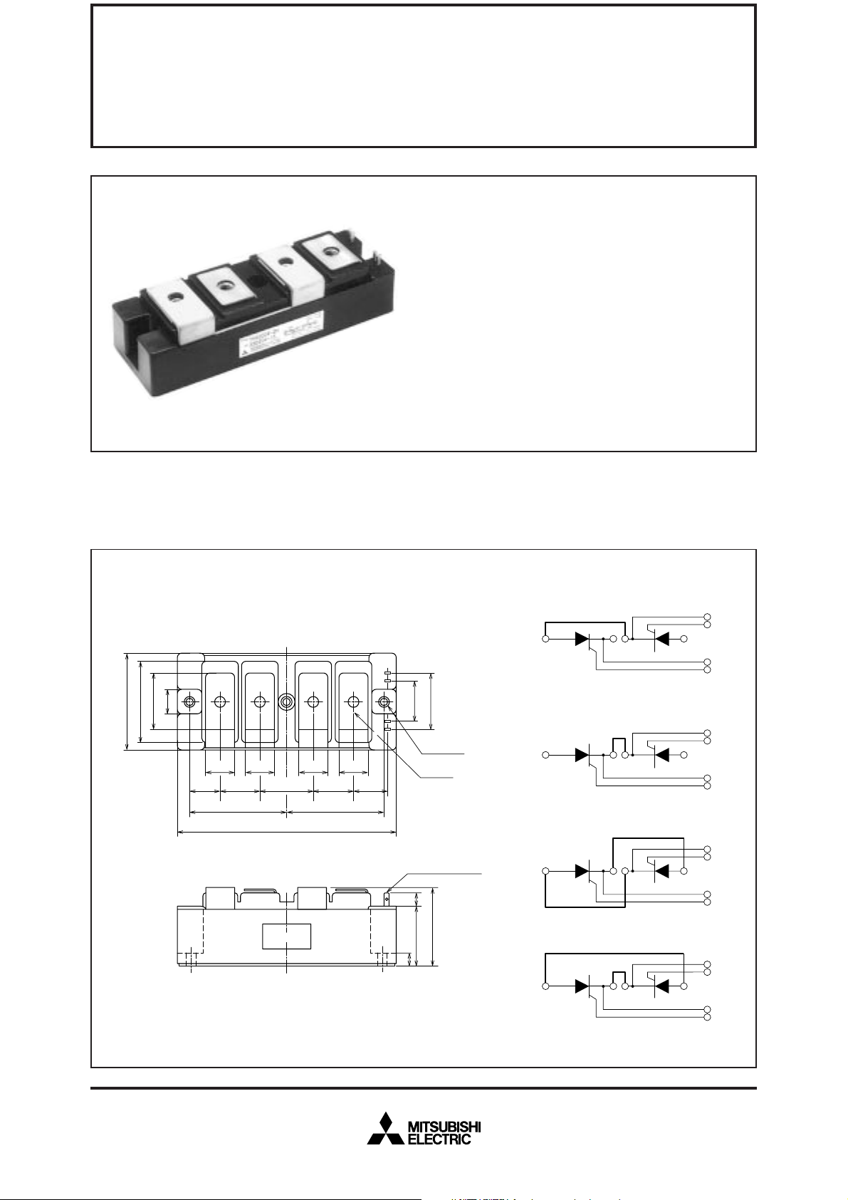
OUTLINE DRAWING & CIRCUIT DIAGRAM Dimensions in mm
(DZ)
K
2
G
2
A
2
K
1
G
1
K
2
G
2
A
2
K
1
G
1
K
2
G
2
A
2
K
1
G
1
60
50
36
16
A
1
K
1
24
24 24 24
80±
0.2
180
CR
CR
1
K1K
2
CR
2
1
K1K
2
CR
2
1
(CZ)
A
A
1
A
K
2
2
2
K
2
G
36
26
1
K
1
G
3–φ6.5
4–M8
2635443523
80±
0.2
(PZ)
CR
1
K1K
Tab#110, t=0.5
9
A
1
2
CR
2
LABEL
(DZ Type)
50
36
9
(UZ)
2
CR
1
A
1
K1K
2
CR
2
K
G
2
A
2
K
1
G
1
(Bold line is connective bar.)
Feb.1999
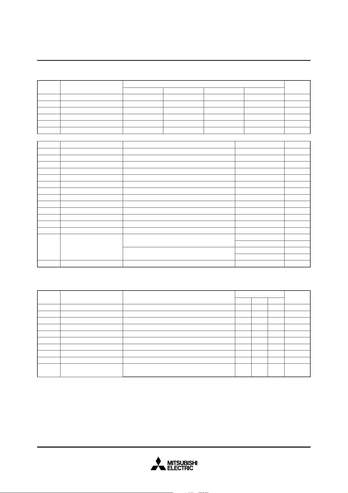
ABSOLUTE MAXIMUM RATINGS
Symbol
RRM
V
VRSM
VR (DC)
VDRM
VDSM
VD (DC)
Repetitive peak reverse voltage
Non-repetitive peak reverse voltage
DC reverse voltage
Repetitive peak off-state voltage
Non-repetitive peak off-state voltage
DC off-state voltage
Parameter
M
400
480
320
400
480
320
MITSUBISHI THYRISTOR MODULES
TM400DZ/CZ/PZ/UZ-M,-H,-24,-2H
HIGH POWER GENERAL USE
INSULATED TYPE
H
800
960
640
800
960
640
Voltage class
24
1200
1350
960
1200
1350
960
2H
1600
1700
1280
1600
1700
1280
Unit
V
V
V
V
V
V
Symbol
T (RMS)
I
IT (AV)
ITSM
2
t
I
di/dt
GM
P
PG (AV)
VFGM
VRGM
IFGM
Tj
Tstg
Viso
RMS on-state current
Average on-state current
Surge (non-repetitive) on-state current
2
t
I
Critical rate of rise of on-state current
Peak gate power dissipation
Average gate power dissipation
Peak gate forward voltage
Peak gate reverse voltage
Peak gate forward current
Junction temperature
Storage temperature
Isolation voltage
—
Mounting torque
—
Weight
Parameter
for fusing
ELECTRICAL CHARACTERISTICS
Symbol
I
RRM
IDRM
VTM
dv/dt
GT
V
VGD
IGT
Rth (j-c)
Rth (c-f)
Repetitive peak reverse current
Repetitive peak off-state current
On-state voltage
Critical rate of rise of off-state voltage
Gate trigger voltage
Gate non-trigger voltage
Gate trigger current
Thermal resistance
Contact thermal resistance
—
Insulation resistance
Parameter
Conditions
Single-phase, half-wave 180° conduction, T
C=66°C
One half cycle at 60Hz, peak value
Value for one cycle of surge current
D=1/2VDRM, IG=1.0A, Tj=125°C
V
Charged part to case
Main terminal screw M8
Mounting screw M6
Typical value
Test conditions
j=125°C, VRRM applied
T
j=125°C, VDRM applied
T
j=125°C, ITM=1200A, instantaneous meas.
T
j=125°C, VD=2/3VDRM
T
Tj=25°C, VD=6V, RL=2Ω
j=125°C, VD=1/2VDRM
T
Tj=25°C, VD=6V, RL=2Ω
Junction to case, per 1/2 module
Case to fin, conductive grease applied, per 1/2 module
Measured with a 500V megohmmeter between main terminal
and case
Min.
—
—
—
500
—
0.25
15
—
—
10
Ratings
620
400
8000
2.7 × 10
200
10
3.0
10
5.0
4.0
–40~+125
–40~+125
2500
8.83~10.8
90~110
1.96~3.92
20~40
1100
Limits
Typ.
—
—
—
—
—
—
—
—
—
—
Unit
A
A
A
5
2
s
A
A/µs
W
W
V
V
A
°C
°C
V
N·m
kg·cm
N·m
kg·cm
g
Max.
60
60
1.4
—
3.0
—
100
0.1
0.05
—
Unit
mA
mA
V
V/µs
V
V
mA
°C/W
°C/W
MΩ
Feb.1999
 Loading...