

Page 1

A
A
A
A
A
A
A
A
Mitsubishi Electric Air Conditioning Network System
Integrated centralized control software TG-2000A
Operation Manual (Site adjustment)
Contents
Please read this manual before using the unit.
Please keep this manual for future use.
WT03901X14
1. Safety Precautions............................................. 1
2. System Requirements ....................................... 3
3. System Configuration ........................................ 11
4. Flow of Site Adjustment..................................... 12
5. Installation.......................................................... 16
6. Part Names and Functions ................................ 37
7. Initial Startup and Shutdown .............................. 46
8. System Setting Procedure................................. 48
8.1 System Setting Screen ............................. 48
8.2 System Setting Procedure........................ 49
8.3 User Set-up............................................... 50
8.4 Site Name Set-up ..................................... 61
8.5 Password Set-up .......................................61
8.6 AG-150A/G-50A Connection Set-up......... 62
8.7 System Configuration Set-up .................... 63
8.8 Set-up DIDO, AI and PI controller.................. 71
8.9 PLC for general equipment set-up ............ 75
8.10 IC I/O Signal Set-up.................................. 80
8.11 Monitoring Screen Set-up ......................... 83
8.12 Watt Hour Meter Set-Up (For RS-485) ..... 92
8.13 Measurement Meter Set-up (For PLC) ..... 93
8.14 Energy Monitoring Set-up......................... 96
8.15 Charge Set-up (For RS-485)....................103
8.16 Charge Set-up (For PLC, PI controller
and without WHM connection)................. 105
8.17 Energy Saving/peak Cut Set-up............... 112
8.18 Night Mode Set-up...................................120
8.19 Auto Change Over Set-up .......................121
8.20 Time Set-up .............................................124
8.21 Monitoring and Changing the Meter
9. Charge Data Correction and Remedy................127
10. Error Code List...................................................153
11. Setting Check List ............................................ 158
Present Value .......................................... 126
9.1 Result of Air-conditioning Charge
Calculation................................................127
9.2 Maintenance of Charge Data ....................129
9.3 Operation Amount Data Monitoring ..........134
9.4 Charge Parameter Output ........................136
9.5 Charging Remedy..................................... 137
9.6 Remedial Apportioning of Charges ........... 148
9.7 Maintenance of Charge Comparison Data
When G-50A and WHM/Measurement
Meter Fail or Are Replaced.......................151
ppendix 1 : Checking the Windows Service Pack
Version and Memory Size…………...194
ppendix 2 : Auto Log-in Confirmation Method......202
ppendix 3 : Correcting the Power Apportioning
Bill When AG-150A/G-50A Fails
or Is Replaced................................... 204
ppendix 4 : Shortening the Charging Test Run....206
ppendix 5 : Backing Up the System Setting Data 209
ppendix 6 : Upgrading the Functions ................... 211
ppendix 7 : Expanding the System ......................214
ppendix 8 : Charging Setting for A and K Control
and LOSSNAY Units......................... 217
2008 - Oct. (Ver. 5.1*/5.5*)
Page 2

Contents
1. Safety Precautions.............................................................. 1
2. System Requirements ........................................................3
2.1 Requirements (system recommendations) ................ 3
2.2 Compatible Units ....................................................... 4
2.3 Restrictions................................................................ 5
2.4 Other Devices.......................................................... 10
3. System Configuration .......................................................11
3.1 System Configuration Example................................ 11
3.2 Hardware Connection Diagram................................ 11
4. Flow of Site Adjustment.................................................... 12
4.1 Flow of Site Adjustment........................................... 12
4.2 Tools for Site Adjustment......................................... 13
4.3 Step 1: Test operation from central controller
AG-150A/G-50A....................................................... 13
4.4 Step 2: Connecting and installing the PLC............... 13
4.5 Step 3: Initial setting of integrated centralized
control software TG-2000A...................................... 14
4.6 Step 4: Test operation from integrated centralized
control software TG-2000A...................................... 15
5. Installation.........................................................................16
5.1 Pre-installation Steps ............................................... 16
5.1.1 Checking the AG-150A version and
the G-50A version.......................................... 16
5.1.2 Preparing for TG-2000A setup.......................18
5.2 TG-2000A Setup(TG-2000A Ver.5.5* or later) ......... 19
5.2.1 Setup ............................................................. 21
5.2.2 Running TG-2000A Setup (New setup)......... 22
5.2.3 Upgrading the TG-2000A version.................. 24
5.2.4 TG-2000A Uninstall ........................................26
5.2.5 Adding files to the ignore list on the
anti-virus software ........................................... 28
5.3 TG-2000A Setup(TG-2000A Ver.5.1*) ..................... 29
5.3.1 Setup ............................................................. 29
5.3.2 Running TG-2000A Setup (New setup)......... 30
5.3.3 Upgrading the TG-2000A version.................. 33
5.3.4 TG-2000A Uninstall ........................................35
5.3.5 Adding files to the ignore list on the
anti-virus software ........................................... 36
6. Part Names and Functions ............................................... 37
6.1 Window Elements.................................................... 37
6.2 Basic Mouse Operation ........................................... 38
6.3 Accessing Functions and Moving between
Windows .................................................................. 38
7. Initial Startup and Shutdown ............................................. 46
7.1 Before startup .......................................................... 46
7.2 Startup ..................................................................... 46
7.3 Shutdown................................................................. 47
8. System Setting Procedure................................................ 48
8.1 System Setting Screen ............................................ 48
8.2 System Setting Procedure....................................... 49
8.3 User Set-up.............................................................. 50
8.3.1 General Operation......................................... 51
8.3.2 Reliability Function ........................................52
8.3.3 Connection Setting ........................................ 53
8.3.4 Energy Saving/Peak Cut and IC I/O
Signal/Interlocked Control Setting ................. 54
8.3.5 Energy Monitoring Related............................ 54
8.3.6 Transmission of Automatic Output File
by email .......................................................... 57
8.3.7 Setting the Warning Sound............................. 58
8.3. 8 Trend Setting .............................................................. 59
8.4 Site Name Set-up ....................................................61
8.5 Password Set-up ..................................................... 61
8.6 AG-150A/G-50A Connection Set-up ........................ 62
8.6.1 Setting Procedure and Restrictions ...............62
8.6.2 Number of AG-150A/G-50A
set-up (Step 1)...............................................62
8.6.3 IP address of AG-150A/G-50A
set-up (Step 2)...............................................62
8.7 System Configuration Set-up....................................63
8.7. 1 Setting Procedure and Restrictions......................63
8.7.2 AG-150A/G-50A data collection (Step 1).........63
8.7.3 Unit composition set-up (Step 2).....................64
8.7.4 Set-up of refrigerant system (Step 3)...............68
8.7.5 Set-up of group (Step 4) ................................ 69
8.7.6 Interlocked setting (Step 5) .........................................71
8.8 Set-up DIDO, AI and PI controller.................................72
8.8.1 Setting Procedure and Restrictions ...............72
8.8.2 DIDO controller (general equipment)
set-up (Step 1)...............................................72
8.8.3 AI controller Set-up(Step 2) ...........................73
8.8.4 PI controller (Meter) Set-up(Step 3) ............... 74
8.9 PLC for general equipment set-up ...........................75
8.9.1 Setting Procedure and Restrictions ...............75
8.9.2 Number of PLC unit set-up (Step 1)...............75
8.9.3 PLC set-up and initial setting (Step 2)............76
8.9.4 Function setting (Step 3)................................77
8.9.5 Advanced setting (air conditioner status
monitor setting) (Step 4) ................................ 77
8.9.6 Advanced setting (Peak cut function
setting) (Step 5) .............................................77
8.9.7 General equipment setting (Step 6)............... 78
8.10 IC I/O Signal Set-up ................................................. 80
8.10.1 Setting Procedure and Restrictions ...............80
8.10.2 General Equipment Set-up (Step 1)...............81
8.11 Monitoring Screen Set-up ........................................83
8.11.1 Configuration Procedure and Restrictions ..... 83
8.11.2 Set-up of model name (Step 1)......................83
8.11.3 Set-up of the number of floors, and
floor name (for sub screen) (Step 2).............. 84
8.11.4 Creation of a sub screen plane view
(Step 3)..........................................................85
8.11.5 Set-up of the number of floors, and
floor name (Step 4)........................................86
8.11.6 Creation of a plan view (Step 5).....................86
8.11.7 Set-up relating a sub screen plan view
and a plan view (Step 6) ................................ 87
8.11.8 Set-up of floor name
and AG-150A/G-50A (Step 7)........................ 87
8.11.9 Set-up of icon arrange and name (Step 8)..... 88
8.11.10 Set-up of block (Step 9) .................................90
8.12 Watt Hour Meter Set-up (ForRS-485) ...................... 92
8.12.1 Setting Procedure and Restrictions ...............92
8.12.2 Watt Hour Meter Setting (Step1)....................92
8.12 .3 Set-up for the Name and the Maximum
Integrated Value of WHM (Step 2).............................93
8.13 Measurement Meter Set-up (For PLC) ................... 93
8.13.1 Setting Procedure and Restrictions ...............94
8.13.2 The number of PLC(s) (Step 1)...................... 94
8.13.3 PLC set-up and initial set-up (Step 2)............94
8.13.4 Measurement meter set-up (Step 3).............. 95
8.14 Energy Monitoring Set-up ........................................ 96
8.14.1 Setting Procedure and Restrictions ...............96
8.14.2 Division mode (Step 1)...................................97
8.14.3 Relation between outdoor Unit
and watt hour Meter (Step 2).........................98
8.14.4 Electrical specification of outdoor units
(Step 3)..........................................................99
8.14.5 Relation between indoor units
and watt hour meters (Step 4) ..................... 100
8.14.6 Electrical specification of indoor units
(Step 5)........................................................101
8.14.7 Charge Blocks (Step 6)................................101
Page 3

8.15 Charge Set-up (For RS-485) ................................................103
8.15.1 Currency unit set ......................................... 103
8.15.2 Charge set ................................................... 103
8.15.3 Standard charge set ....................................104
8.16 Charge Set-up (For PLC, PI controller
and without WHM connection)............................... 105
8.16.1 Setting Procedure and Restrictions............. 105
8.16.2 Currency unit set (Step 1)............................ 105
8.16.3 Basic charge setting (Step 2).......................106
8.16.4 Season period setting (Step 3) .................... 106
8.16.5 Weekly charge setting ................................. 106
8.16.6 Annual charge setting.................................. 108
8.16.7 Setting the meter unit price.......................... 111
8.17 Energy Saving/Peak Cut Set-up ............................112
8.17.1 Energy saving setting .................................. 112
8.17.1.1 Setting Procedures and Restrictions....... 112
8.17.1.2 Energy saving setting (Step 1) ................ 112
8.17.2 Peak Cut Setting ........................................ 115
8.17.2.1 Setting Procedures and Restrictions....... 117
8.17.2.2 Peak cut WHM setting (Step 1)...............117
8.17.2.3 Peak cut setting (Step 2)......................... 118
8.18 Night Mode Set-up................................................. 120
8.18.1 Setting Procedure and Restrictions............. 120
8.18.2 Night Mode Set-up ..................................... 120
8.19 Auto Change Over Set-up .....................................121
8.19.1 Setting Procedure and Restrictions............. 121
8.19.2 Auto change over set-up (Step 1) ................ 122
8.20 Time Set-up ........................................................... 124
8.21 Monitoring and Changing
the Meter Present Value........................................ 126
9. Charge Data Correction and Remedy............................. 127
9.1 Result of Air-conditioning Charge Calculation........ 127
9.2 Maintenance of Charge Data................................. 129
9.2.1 Preparing for Charging Data Maintenance ..129
9.2.2 Maintenance Methods and Restrictions....... 129
9.2.3 Unit Data Maintenance................................ 130
9.2.4 Watt Hour Meter Data Maintenance ............ 133
9.2.5 Verify Test Operation of Watt Hour Meter.... 134
9.3 Operation Amount Data Monitoring .......................134
9.4 Charge Parameter Output ..................................... 136
9.5 Charging Remedy.................................................. 137
9.5.1 Remedial apportioning setting screen
(RS-485)...................................................... 137
9.5.2 Remedy when computer HDD fails
(no backup).................................................. 140
9.5.3 Remedy when computer HDD fails
(backup)....................................................... 142
9.5.4 Apportioning method when computer
crashes........................................................ 143
9.5.5 Remedy when watt hour meter fails
(monitoring impossible) ...............................145
9.5.6 Remedy for system information
setting error .................................................147
9.6 Remedial Apportioning of Charges ........................ 148
9.6.1 Preparing for remedial apportionment of
charges........................................................ 148
9.6.2 Remedial Apportionment Set-up window
(PLC) ........................................................... 149
9.7 Maintenance of Charge Comparison Data When
AG-150A/G-50A and WHM/Measurement
Meter Fail or Are Replaced.................................... 151
9.8 Maintaining the charge data by deleting the
carry over amount for the unused unit prices ....... 152
10. Error Code List................................................................ 153
11. Setting Check List .........................................................158
11.1 Setting Check List ................................................ 158
11.2 Test Run Check ................................................... 159
11.3 Charging Test Run Check ....................................162
11.3.1 Charging (No WHM connection)
Test Run Check........................................... 162
11.3.2 Proportionally Divided Power Charge
(RS-485 WHM connection) Test Run
Check...........................................................168
11.3.3 Test run check of power apportionment
billing (Electric amount pulse count) ............ 174
11.3.4 Charging test run operation methods...........182
11.4 Energy saving and peak cut checks ...................... 183
11.5 System information CSV Output..................................186
11.5.1
Air Conditioning Unit Start/Stop Information
CSV Output ................................................186
11.5.2 Test Run for the Charge Function Information
CSV Output .................................................. 187
11.5.3 Create a Test Run Check sheet..................... 188
Air Conditioning unit start/stop test check sheet ...190
Test run for the charge function check sheet......... 193
Appendix 1 : Checking the Windows Service
Pack Version and Memory Size ..................... 194
Appendix 2 : Auto Log-in Confirmation Method.................. 202
Appendix 3 : Correcting the Power Apportioning Bill When
AG-150A/G-50A Fails or Is Replaced ........... 204
Appendix 4 : Shortening the Charging Test Run................ 206
Appendix 5 : Backing Up the System Setting Data ............ 209
Appendix 6 : Upgrading the Functions............................... 211
Appendix 7 : Expanding the System.................................. 214
Appendix 8 : Charging Setting for A and K Control and
LOSSNAY Units............................................ 217
Page 4

In this manual, Microsoft® Windows Vista® Business is called Windows Vista, Microsoft® Windows® XP
Professional is called Windows XP and Microsoft® Windows® 2000 Professional is called Windows 2000. In
this manual, Microsoft® Excel 2007/2003/XP/2000 is called Excel.
Trademarks
MS, Microsoft, Microsoft logo, and Windows are registered trademarks and trade names of Microsoft
Corporation. Adobe logo, Acrobat, Adobe PDF logo, Reader are registered trademarks and trade names
of Adobe Systems Incorporated.
Each company may use as registered trademarks and trade names the product names used in this
manual.
-About this manual-
The operation manual consists of three volumes, “Site adjustment”, ”Management”, and ”Wide area”.
This manual is “Site adjustment”. These manuals are accessible from the Help menu on TG-2000A.
Acrobat® Reader is required to read these manuals. (Ver. 5.0E or later recommended)
– Term description –
• “Man-machine” : Indicates a computer with integrated centralized control software TG-2000A.
(Man-machine interface abbreviation)
• “AG-150A” and ”G-50A”:
Refer to centralized controllers AG-150A and G-50A.
On the screen of integrated centralized control software TG-2000A, AG-150A and
G-50A may appear as AG-150A/G-50A, AG-150/G-50, or G-50.
TG-2000A Ver.5.50 or earlier does not support AG-150A connection. Unless otherwise
specified, read AG-150A/G-50A as G-50A in this manual.
•
"PLC" : Abbreviation for Programmable Logic Controller.
The TG-2000A system uses two PLCs; the electric amount count software and PLC for
general equipment software.
The electric amount count software measures the electric amount with the PLC, the
general control operates and monitors the general equipment, etc.
• "Power apportioning billing"
Billing support function that apportions the electric amount used by the air
conditioner. The following three methods are available:
Manual electric amount input
... A watt hour meter (WHM) is not connected, and instead the charge percentage is
calculated according to the percentage of power used. The service power is
measured with the separately installed WHM, and the service charges are
obtained from the charge percentage.
Electric amount pulse count
... The electric amount is measured by the PLC, and the service electric amount is
monitored by via the LAN to automatically apportion and calculate the electricity
charges.
The designated PLC and optional software are used.
Direct read in of power value into computer
... The RS-485 output watt hour meter is directly connected to the computer
containing the integrated software (via an RS-232-C/RS-485 converter), and the
service power is input.
The service power rate is automatically apportioned and calculated.
• "WHM" : Abbreviation for Watt Hour Meter.
• "Service power rate":
The service power rate indicates the power rate (apportioned rate) apportioned
based on the service state of the air conditioner, etc.
• "Always connected to AG-150A/G-50A system - Activate": <Recommended mode>
Refers to charging method that is operated by connecting this integrated centralized
control software TG-2000A constantly to the AG-150A/G-50A and PLC via a LAN.
Leave the computer power ON to keep the TG-2000A running.
PI controller instead of the PLC can be connected.
Page 5

• "Always connected to AG-150A/G-50A system - Deactivate":
Refers to charging method that connects this integrated centralized control software
TG-2000A to the AG-150A/G-50A and PLC once a month via the LAN. The charges for
the last month are calculated and output at once. The charging function can be used
efficiently by starting the computer and integrated centralized control software
TG-2000A on the day after the set settlement date.
PI controller instead of the PLC can be connected.
"IC I/O signal" : Refers to a contact mounted on the air conditioner's indoor unit. A general equipment can
•
be connected to the IC I/O signal using this contact and a PLC for general equipment to
operate and monitor the system.
"DIDO controller": Refers to the controller (PAC-YG66DCA) that can monitor or control general
•
(DC) equipment.
•
"AI controller" : Refers to the controller (PAC-YG63MCA) that has a function to measure temperature
(MCT) and humidity.
•
"PI controller" : Refers to the controller (PAC-YG60MCA) that has a function to calculate cumulative
(MCP) pulses from such metering devices as watt-hour meter.
- About screen -
• This instruction manual may use the development version screen in some case.
- Simple operation manual -
• A simple operation manual is available in addition to this instruction manual (Site adjustment, Management).
The simple operation manual is stored as a pdf file in the "Manual" folder on the TG-2000A Setup CD.
Acrobat Reader (Version 5.0E or later recommended) is required to view this pdf file.
Page 6

Page 7

r
pany
p
t
1. Safety Precautions
• Please read the Safety Precautions section very carefully before using the unit.
• The safety cautions provided here are very important for your safety. Please observe them at all times.
• The degree of danger involved with incorrect operation of the unit are indicated in this manual using
the following symbols.
WARNING Incorrect operation could result in death or severe injury.
CAUTION Incorrect operation could result in injury or damage to property.
• After reading this information, please keep this manual together with the operation manual (Management)
in a location where the operator can see it. Also, when changing operators give both of these manuals to
the new operator.
Note : Please observe the safety precautions de tailed in the installation manua ls an d ope rat ion
manuals of the other machines such as computers, peripherals, and air conditioners.
WARNING
The customer must not do any wiring or
electrical work.
Have the dealer or a specialist do any wiring or
electrical work. Do not do it yourself. Doing the
work yourself may result in improper installation
which may cause electric
Do not make any improvements or repairs
for any reason.
Making improper improvements or repairs may
cause electric shock or fire. For repairs, consult
the com
Stop operation immediately if an error
message appears on the computer and the
unit stops or is no t ope r ati n g pro p erly.
Failing to do so may result in fire or damage to
the unit. Immediately contact the company from
which the uni
Do not use the product for any other
purpose.
This product is for use with the Mitsubishi
Electric Building Air Conditioning Control
System. Do not use it with any other air conditioning control system or for any other application. Doing so may cause the unit to malfunction.
Do not use with other applications.
Use the PC that uses this product with this
product only. Using it with other applications
may cause faulty operation.
Warning to all users (User Agreement)
This document is a contract between the customer and Mitsubishi Electric Corporation. By using this
application, you agree to the following conditions and are considered a user.
• Mitsubishi Electric and associated suppliers are not responsible for any collateral, secondary, o
special damages, even if notified by the distributor of the possibility of a certain type of damage.
Mitsubishi Electric is not responsible for any rights claimed by a third party.
from which the unit was purchased.
was purchased.
CAUTION
Do not relocate the unit yourself.
Relocating the unit yourself may result in
incorrect installation which may cause electric
shock or fire. To relocate the unit, consult the
company from which the unit was purchased.
Read the installation manuals and operation manuals for the computer, peripherals
and other machines.
Improper operation could result in fire or damage
to the com
Read the installation manual and operation
manual for the air conditioner controller.
Improper operation could result in fire or damage
to the air conditioner controller.
Keep children away from the unit.
Inspections and maintenance can be
dangerous. Do not let children near the unit
during these times.
uter or peripherals.
1
Page 8

Safety Guidelines for the Computer Running the with the TG-2000A.
a
s
A
e
e
a
e
r
y
t
A
a
g
s
o
e
A
e
(1) Precautions for selecting a computer
Select a desktop computer.
• Depending on the function, it is recommended to use
desktop as opposed to a laptop computer as there i
a tendency for heat to build up in a laptop.
• Some laptop computers cannot be run for long
hours.
Use a computer/operating environment with specifications capable of running the TG-2000A function.
• Run the function using the specified OS. There is a possibility that the function cannot be used when running an
OS other than specified.
• Use a busine ss model computer . There are cases when it is not possible to install or run the application with
other applications on a computer or laptop intended for personal use.
Computer based UPS recommended.
• It is recommended to use a UPS to protect data from
momentary power outages or power cuts.
It is particularly recommended to employ a UPS when
using power apportioning billing.
(2) Precautions for General usage
Do not place the computer in any of the following
locations.
•
following environments.
A place where there is: a lot of dust, a likelihood of
shock or vibration, instability, a heater or speaker
nearby, direct exposure to sunlight, a likelihood of
dropping, a possibility that the computer may be
exposed to moisture or high temperature, or where it
may be exposed to sudden temperature fluctuations or
heat.
Do not close the lid when using a laptop.
• There is a possibility of an internal temperature build-up,
fire or burning. Use in an area with sufficient ventilation.
• The system may start Stand By or Hibernate function
and stop functions of TG-2000A by closing the lid.
Do not touch the computer air vent.
• The air emitted by the ventilator is hot and may result in
burning if exposed to the skin.
Do not tamper with the computer fan .
• Tampering with the computer fan may result in
temperature build-up, fire, or accident.
n error or accident may occur when using in th
Ensure to read the computer/peripheral
instruction manual.
• A fire or accident may occur due to improper use of th
equipment.
void covering the computer or AC adapter with
a cloth or blanket, or locating them on or near
heater.
• There is a possibility of internal temperature build-up,
fire or burnin
under the above situations.
Cut the poweror disconnect the power cabl
immediately if smoke, or an abnormal smell o
noise emanates from the computer .
• Using the computer in the above circumstances ma
result in fire, burning, or electric shock. Please consul
the maker of the equipment/computer.
Use the hard disk, floppy disk, or CD media a
indicated.
• Do not expose the hard disk, floppy disk, or CD t
shock or vibration during use.
• Do not cut the power or reboot the computer while th
hard disk, floppy disk, or CD is in use.
•
lways turn OFF the power when moving th
computer.
Note: Refer to chapter 2 and 5.
(3) Other precautions
Precautions relating to the computer and peripheral equipment
• Please consult the maker regarding damage to the computer or peripheral equipment. We will not be held
responsible for damage occurring at the user’s site.
Safety Guideline for LAN connection of AG-150A/G-50A
Connect AG-150A/G-50A to a private network.
• AG-150A/G-50A are designed to be used with TG-2000A on a private network.
• Use a security device such as a VPN (Virtual Private Network) router when connecting to the Internet.
2
Page 9

2. System Requirements
2.1 Requirements (system recommendations)
TG-2000A version System Requirements
AG-150A and G-50A compatible
TG-2000A
To use the functions supported by
older versions of G-50A compatible
TG-2000A
*1 Upgrade TG-2000A V er . 5.20 to V er.5.5* or later.
TG-2000A Ver.5.5* or later
TG-2000A Ver.5.1* OS: Windows XP/2000
We recommend the following software and hardware when using this application (TG-2000A).
Item Requirement Recommended
PC PC/AT interchangeable machine
(Recommended: IBM, HP,DELL)
CPU
HDD
Storage
device
Resolution 1024 × 768 or higher, 65536 colors or more
Serial port 1 port or more Required when using RS-485 communication WHM
LAN 1 port (10BASE-T/100BASE-TX) *1
Modem 56K modem or TA Required when using a modem in wide area
USB 2 port or more It uses it for the data backup.
OS
Other Computer must be dedicated for this use
CoreTM 2 Duo 1.66GHz or faster
(Windows Vista for Core 2 Duo)
Pentium® M 1.7GHz or faster Pentium® M 2.0GHz or faster
Pentium
In Windows Vista : 1GB or more 2GB or more Memory
In Windows XP / 2000 : 512MB or more 1GB or more
Standard 6 GB or more (2GB or more of C
Wide area 20GB or more (Free space) Standard : max. 200MB/site
FDD, CD-ROM drive Devices other than those shown at the left may
Windows Vista® Business
Windows® XP Professional
Windows
*Use TG-2000A Ver.5.1* for Windows® 2000
Professional.
(TG-2000A).
® 4 2.4GHz or faster Pentium® 4 2.8GHz or faster
drive free space necessary)
Service Pack 1 *2
Service Pack 3 *2
® 2000 Professional
Service Pack 4 *2
Operation check completed, using IBM, HP and
DELL (Business model is recommended)
Core
40GB or more of C drive free space necessary
When using the trend function, the drive used for
automatic output must have the following free
space according to the number of groups.
200 groups = 2GB, 500 groups = 5GB, 1000
groups = 10GB, 2000 groups = 20GB
also be installed.
(Not necessary when using PLC)
mode.
English version only
*Computer must support each OS.
English version only
*Computer must support each OS.
English version only
*Computer must support each OS.
Must be used for 24-h o ur constant operation
(Only some functions. Refer to sectio n 2.3 for
details)
*1 Purchase the option, or use the equipment recommended for the computer when purchasing the
computer.
*2 It is necessary to correspond to each Service Pack. TG-2000A is not normally set up at the
uncorrespondence. Please apply Service Pack of the correspondence.
OS: Windows Vista/XP
*1
(Not compatible with Windows 2000)
Refer to the table below for details.
(Not compatible with Windows Vista)
Refer to the table below for details.
TM
2 Duo 2.4GHz or faster
3
Page 10

2.2 Compatible Units
The TG-2000A has two main functions: air conditioner controller and cost accounting. However, not all
functions are available with all air conditioners.
Table: Compatible units and function list (: supported, ∆: Certain restrictions apply, ×: Not supported)
Function
Model
Y series *1
Super Y series *1
R2 series *1
WR2 series *1
WY series *1
Multi S series *1 *5
Free plan Indoor unit *2
Free plan LOSSNAY *3 △*6
OA processing unit *1 △*7
“A” control type *4
“K” control type *4
Room Air Conditioner
Air To Water Booster
unit
Air To Water HEX unit × × × ×
*1: Can be calculated for each charging block. May not be available with some older models.
*2: Indoor unit models before Free Plan models do not support a charge apportioning billing method based on the
“capacity save.” The existence of even a single unit of those types in the system requires that the method of
charge apportioning billing be set to either “Thermo on time” or “Fan operation time.”
Certain restrictions apply to large-capacity indoor units when malfunctions occur.
*3: LOSSNAY groups to which the remote controller is connected support the charging system.
*4: Not all of the A-control and K-control units support these functions. (e.g., The calculation of the charge for the
auxiliary heater may not be handled by these units.)
*5: Outdoor unit capacity control function is not available.
*6: Only the function to stop the units is available.
*7: When the attribute is IC (indoor unit): Same type of energy-save control unit as with the Freeplan Indoor unit is
When the attribute is FU (LOSSNAY with a heater/humidifier): no direct energy-save control is possible.
*8: Inverter models support the outdoor unit capacity save control function.
*9: Outdoor unit Thermo-OFF control function is not supported. Only the fan control function is available.
*10: Only the temperature control function or the function to stop the units is available.
Control/
Maintenance
(Adapter required)
(Converter required)
(Adapter required)
× × × ×
Charging (Billing)
without WHM
possible.
Charging (Billing) with WHM
*1 △*8
*1 △*9
× △ (Requires separate watt
hour meters. Bills calculated
based on the reading of each
watt hour meter)
Energy
Saving/
Peak Cut
△*10
4
Page 11

2.3 Restrictions
The following restrictions apply to the TG-2000A application.
(1) System configuration limits
Use TG-2000A with the vers ions described in this manual with AG-150 Ver. 1.0* or later or with
G-50A Ver. 3.22 or later.
Number of units Notes
AG-150A/G-50A Max. 40 units
Indoor unit Max. 2000 units (including all IC,
KIC, AIC, LC, FU, MCT, MCP
and DC *12)
General equipment
(PLC)
General equipment
(IC I/O signal)
PI controller (MCT)
*14
Meter *14 Up to 160 units (5 PLC units for
[Symbol] IC: Indoor unit, LC: LOSSNAY, FU: OA processing unit, AIC: “A” controller,
KIC: “K” controller, MCP:PI controller, MCT:AI controller, DC:DIDO controller
*1: The version can be confirmed with the method explained in section 8.6.3.
*2: Use G-50A Ver. 2.31 or later to use the power apportioning billing function.
*3: Use G-50A Ver. 2.50 or later to use the energy saving/peak cut function.
*4: Only 32 units each can be connected for the PLC for general equipment. These are the general equipment No.
1**-1 to 32 listed in Section 8.9.4. 33 to 100 cannot be used due to restrictions for the PLC for general
equipment.
*5: When G-50A is more than Ver.2.50, TG-2000A of Ver.2.00 does not operate.
*6: Use G-50A Ver. 2.60 or later when using the night mode or auto change over function.
*7: Up to 350 general equipment units can be connected to the IC I/O signal with each G-50A. However, the
integrated software TG-2000A can control only up to 2000 general equipment units connected to the IC I/O
signal. Use G-50A Ver.2.70 or later when using the IC I/O signal function.
*8: The combination use of TG-2000A Ver4.70 and G-50A Ver2.71 expands the set temperature range limit
function (such as the upper limit of the set temperature for the Cool (Dry) mode, the lower limit for the Heat
mode and the upper and the lower limit for the Auto mode).
*9 The combination of TG-2000A Ver.4.80 and G-50A Ver.2.51 support a charge apportioning billing method of
A-control and K-control units.
*10 When using G-50A initial setting Web, the combination of G-50A Ver.2.80 or later and TG-2000A Ver.4.80 or
later must be used.
*11 When using the 1ºF temperature setting function, use the combination of G-50A Ver.3.00 or later and
TG-2000A Ver.5.00 or later. The indoor unit supporting the 1ºF temperature setting function is also required.
*12 1 contact point for DIDO Controller is converted to 1 unit. Up to 50 units are connectable to each AG-150A/G-50A.
*13 DIDO Controller, AI Controller and PI Controller are supported by G-50A Ver.3.20 and TG-2000A Ver.5.10 or later.
*14 Only either PLC or PI Controller can be connected for meter connection. Bo th ca nnot b e conn ected at the same time.
(2) Group setting restrictions
Item Restrictions Note
Remote controls 2 per group * Other remote controls besides M-NET type will not work *1
Number of indoor units
connected to a group
Number of SC and RC
connected to a group
Groups per floor
*1 The ME remote controller and MA remote controller cannot be used together for the same group.
*2 Set the same function unit for the group.
*3 Set units with different models or functions in another group.
[Symbol] SC: System controller, RC: Remote controller, DC: DIDO controller
Up to 640 units (including 20
PLCs for general equipment)
Up to 2000 units *7 Max. 350 units/(AG-150/G-50A)
UP to 40 units *13
(Up to 160 meters)
power rate pulse count)
1 to 16
4 per group * The number of AG-150A/G-50A is not included
Max. 50 groups
per floor
AG-150A Ver.1.0*
G-50A Ver. 2.10 or later *1,2,3,4,5,6,8,9,10,11
Max. 50 units/
(AG-150/G-50A) *12,13
Max. 32 units/PLC
Max. 5 units/(AG-150/G-50A)
Max. 40 units/TG-2000A
Max. 32 units/PLC
* IC, AIC, KIC, LC and DC cannot be used within the same
group. It is not possible for group settings to span
AG-150A/G-50A *2,3
Up to 50 groups can be displayed on one floor of the whole
building window.
5
Page 12

(3) Block setting
• The block comes in two types, operation block and charge block.
• The operation block is an aggregate of groups, and it is possible to set a different model group
for the same operation block.
• The charge block consists of an aggregate of operation blocks.
* The blocks controlled with the AG-150A/G-50A browser are the same as the operation blocks.
Operation blocks extending over AG-150A/G-50A can be set only with the integrated software TG-2000A.
• The operation block should be set individually for the K-control model, A-control model, DIDO
controller, LOSSNAY and free plan indoor unit.
(4) Notes on using K-control models
When using a K transmission converter (model name: PAC-SC25KA, PAC-SC25KAA(-E)) to
manage K-control models, take note of the following. See the documentation provided with the K
transmission converter for more detail.
• The address of the K transmission converter will be the smallest address of the K-control model
+ 200.
• Set the K control model addresses so that they are larger than the M transmission model addresses.
• When setting a group containing K-control models, make the group number the same as the smallest
unit address in the group.
• K-control LOSSNAY models are not applicable.
Group
Block for operation
Block for charging
(5) Notes on using A control mode
• Use the A/M-NET Adapter (model name: PAC-SF48MA(-E)). Set the group to “Group with only
A-control”.
(6) Countermeasure when an error occurs
• Note that each control or function may not operate properly when rebooting (*1) or when a fault
occurs in the central controller AG-150A/G-50A or other controllers and so on. Since each error
is displayed when it occurs, it is recommended to solve the faults quickly.
*1 Indicates that the system is restarting.
(7) Notes on charge system
• This charge system does not actually calculate the power consumption by each air
conditioning unit. Rather, it helps calculate the capacity output of each air condit ioning
unit, using the unique apportioning method developed by Mitsubishi.
Mitsubishi shall not be held responsib le for any problem or damage resulting from the
use of TG-2000A, including but not limited to the cases as described in section (8) below.
• If there is a group that is not set in the charge block, the electric power amount for that group will
not be included in the air-conditioning charge. If there are groups which require charging to be
divided, set those groups as operation blocks or charge blocks to accomplish this.
• Some older M-NET control indoor units are not compatible with the charge function.
• When the system is changed or the air conditioner is extended, which may require address
changes, the charge calculation may be affected in some cases.
Executing such changes or extensions are recommended after gaining approval from the
building owner(s).
• Irregular processes, such as repeated apportioning of power or non-apportioning of power (*1),
may occur due to communication errors with the central controller AG-150A/G-50A , PLC or PI
controller , etc. If the rates are not apportioned, a recovery process must be executed with the
charge maintenance function, etc.
*1 For power apportioning billing function's (Direct read in of power value into computer) function
• The power rate accuracy relies on the watt hour meter. The measurements for the gas, etc.,
also rely on the meters, so an error could occur in the accuracy during operation.
6
Page 13

• When using the power apportion billing in the always connected to AG-150A/G-50A system
state, the integrated centralized control software TG-2000A must be run at all times (24-hours).
The air conditioning rate results will appear in red if the software stops. When using the direct
read in of power value into computer function (RS-485 WHM), power apportion billing in the
always connected to AG-150A/G-50A system state is used.
• Only one of PLC (PAC-YG11CDA), PI controller (MCP), and RS-485 can be connected with
watt hour meter. The system cannot accept the mixed connection. Also, in the case of using
RS-485, some functions are restricted.
• Perform the “Charging Test Run Check” as described in section 11.3 before using the
apportioned electricity charge function.
(8) Charging (Billing) restrictions
The air conditioning cost calculation method use by this integrated centralized control software
TG-2000A is the Mitsubishi proprietary general electric power apportioning method.
Depending on each country's laws and regulations, etc., there may be cases these measured
charges cannot be used for certificate of transaction.
Before starting use, the building owner and building tenant should bind an agreement or
contract indicating that the air conditioning charges are part of the usage fees with an
independent contract indicating "The air conditioning charges are collected with an apportioning
method that considers the air conditioner's operation state instead of charges according to the
measured power rate (including during emergency operation when a failure occurs)".
(1) A watt hour meter is not installed on each air conditioner's power supply section to calculate
the rate.
(2) This system cannot be used for applications requiring calculations made by installing a watt
hour meter on each air conditioner.
(3) This system estimates the air conditioner apportioned power rate, and cannot be used as a
certificate of transaction.
(4) Even if the air conditioner is run for the same length of time, the air conditioning charges
may differ according to the air conditioner's operation load state.
(5) Even if one or several air conditioners are connected to one watt hour meter, the watt hour
meter apportions with the total power rate. Thus, an error could occur. Multiple air conditioners
are considered as one air conditioner when apportioning and calculating.
(6) The air conditioner is energized even when stop, so the air conditioning charges are
calculated even if the air conditioner is not used.
(7) If a fault occurs in the computer, AG-150A/G-50A, PLC or PI controller, remedial measures
will be taken with the past average apportioned rate, etc.
(8) Mitsubishi will not be held liable in any case as the watt hour meter and gas meter, etc.,
rates are retrieved as pulses, and the performance and accuracy rely on the meters.
* The gas meter, etc., also counts with a pulse converter and thus cannot be used as a certificate
of transaction.
Note that the counted value includes remedial measures taken when a fault occurs.
(9) Energy saving and peak cut functions
• Note that when using the peak cut function, Mitsubishi will not be held liable even if faults occur
when the service power rate exceeds the contracted power rate value due to the control
operation settings or a fault in the AG-150A/G-50A, PLC or PI controller.
• The energy saving and peak cut control units are the operation block and outdoor unit in the
AG-150A/G-50A unit.
• During peak cut control (for PLC(PAC-YG11CDA)), the AG-150A/G-50A monitors only one watt
hour meter. This can be set for each AG-150A/G-50A. This cannot be used with a system for
which two or more watt hour meters are connected to the air conditioner controlled by one
AG-150A/G-50A. Use the power rate count software Version 1.01 or later.
• During peak cut control for watt hour meter connected with PI controller, only one watt hour
meter monitored by the AG-150A/G-50A can be selected. When using other AG-150A/G-50As
for peak cut control (*1), up to three AG-150A/G-50As can be connected with the
AG-150A/G-50A.
*1:AG-150A/G-50A, connected with watt hour meter, monitors peak cut control lever every one minute. When the
control level changes, the change reflect AG-150A/G-50As with one minute delay. Control level should be set with
some float to avoid over peak cut electric power.
• During peak cut control (for Demand control equipment), up to 10 AG-150/G-50As can be monitored
with PLC for demand input software. When using more than 10 AG-150A/G-50A s, install multiple
number of PLCs. PLC for demand input software (PAC-YG41CDA) should be used for PLC.
7
Page 14

(10) Set temperature range limit function
• On ME remote control system, the target for the temperature range limit setting is only ME remote
controller and individual browser.
• On MA remote control system, the target for the temperature range limit setting is only MA remote
controller and individual browser. This function cannot be used depending on the indoor unit model.
(On MA remote control system, TG-2000A is supported by Ver.5.10 or later, and G-50A is supported by
Ver. 3.20 or later.)
Valid remote controller Set temperature range
limit
PAR-F27MEA-E Partly possible *1 ME remote controller
PAR-F27MEA-F Possible
PAC-SE51CRA-E Impossible ME simple remote
controller
PAC-SE51CRA-F Possible
MA remote controller PAR-21MAA Possible *2
PAC-YT51CRA Impossible Simple MA controller
PAC-YT51CRB Possible *2
*This chart is for TG-2000A Ver4.70 and G-50A Ver2.71systems.
*1 Only the lower limit of the set temperature for the Cool (Dry) mode and the upper limit for the Heat mode can be set
with the ME remote controller, PAR-F27MEA-E.
For ME remote controller, model name is written on the packing label or on the notice sticker on the backside of the
remote controller lid.
For ME simple remote controller, model name is written on the packing label or on the rated nameplate of the remote
controller.
*2 This function cannot be used depending on the indoor unit models. This chart is for TG-2000A Ver5.10 (or later) and
G-50A Ver3.20 (or later) systems.
(11) Initial settings
• Even if the operation settings are unclear, set all of the initial setting items selected for use.
Some functions may not work if any setting is omitted.
• In addition to installing (setting up) the PLC software, the PLC must be initialized from the
TG-2000A.
• Make sure the clock is synchronized with the clocks on AG-150A/G-50A and PLC.
Resynchronize the clock as necessary.
(12) Operation of the integrated centralized control software TG-2000A
• Either "Activate" or "Deactivate" can be selected for "always connected to AG-150A/G50A
system" of the TG-2000A. *Recommended setting: “Activate”
• When "Activate" is selected, the following functions are carried out automatically. When
"Deactivate" is selected, these are carried out semi-automatically.
• Power apportion billing data collection
• Apportioning, settlement calculation process
• Automatic output of settlement results
• The functions that run in the "always connected to AG-150A/G50A system" state can be used in
"Activate" state, but cannot be used in the "Deactivate" state. These functions will not operate
when the system is stopped.
• Trend functions (temperature, on/off, mode, power amount, humidity)
• Peak cut functions (only peak cut operation history functions)
• Set the TG-2000A to the "Deactivate" state when using the following functions.
• Summer time ----- From the day prior to and after shifting to and from summer time
• Season period --- From the day prior to and after shifting between normal and seasonal
power apportion billing.
• The G-50A, PLC or PI controller errors cannot be detected while the TG-2000A is stopped.
If the G-50A, PLC or PI controller is faulty, stopped or the power is OFF, the data required for charging
will not be collected, and schedule operation of the air conditioner or general equipment will not be
possible. Periodically confirm that the operation is correctly, and that no abnormalities are occurring.
• When "Activate" is selected, leave the computer power ON so that the integrated software
TG-2000A program runs 24 hours. (to prevent the program from stopping, do not use the
"System standby" or "System halt state" power supply optional functions.)
• The integrated software TG-2000A program runs for 24 hours, so always leave the computer's
power ON.
• Do not put any access restrictions such as “Read Only” on the folders on WINDOWS, TG2000,
MSSQL7, or on the ones that are specified in the user settings window of TG-2000A.
(13) Computer name
• Never change the computer name when setting up the integrated centralized control software
TG-2000A. The software will not operate if the computer name and the server name are
different.
8
Page 15

(14) Expanding billing target devices
• Always stop the air conditioner, fan and power rate count PLC or PI controller,
before expanding the devices.
• The billing function and power count function will not work correctly while the devices are being
expanded.
• Always change and check the system settings with the TG-2000A after finishing the expansion work.
Always test the operation after changing and checking the system settings.
(15) Using general equipment
• There may be cases when the general equipment cannot be monitored or operated due to a
disconnection in the wiring with the general equipment or a fault in the PLC (or DIDO controller).
Mitsubishi will not be held liable in the event of any damage. A circuit should be provided for
remedial operations when a fault occurs.
• The license number does not need to be registered in the AG-150A/G-50A when using the PLC
for general equipment software Version 1 Series.
(16) Function description
• The function/specifications may partially change and improvements may be made without any
notice.
(17) TG-2000A License
* Refer to the end of "Safety Precautions" in Chapter 1.
9
Page 16

2.4 Other Devices
Other devices specified or recommended for use with the TG-2000A are listed below.
Name Manufacturer Model Notes
HUB (None specified) (None specified) 10BASE-T must be usable.
Printer (None specified) (None specified) Supports a page printer only
(Must run under the OS used
(Windows Vista/XP/2000).)
Watt hour meter
(RS-485)
RS-232C/
RS-485
converter
PLC
* For electric
amount pulse
count
* For PLC for
general
equipment
software
(Ver. 1 Series)
1 Northern Design
(Electronics) Ltd.
2 Elcomponent
Limited
3 CIRCUTOR
4 Elcontrol energy
1 POWER RAIL 323 +
OPTION Module
2 AEM31D/485
3 CVM-BC-ITF-RS485-
C2
4 ED39din 485
Only supports RS-485 output of
the specified model and
manufacturer
(None specified) (None specified) Necessary when measuring the
electric power.
Ex) B&B Electronics Model
485DRJ
Black Box Model IC520A-F or
IC108A
* Regarding watt hour meter 2,
the converter from the manufacturer may also emit light.
Mitsubishi Electric CPU module : Q02CPU
Base module : Q33B
Power supply module:
Q61P-A1
or Q61P-A2
Input module : QX40
Output module:
QY40P
Ethernet module:
QJ71E71-100
These are used for the power
apportion billing (electric amount
pulse count) or general equipment
operation/monitor function.
Dedicated PLC software (PACYG11CDA, etc.) is required for
each function.
* The output unit is not required
for the electric amount pulse
count PLC.
PLC
* For PLC for
general
equipment
software
(Ver. 2 Series)
* For PLC for
demand input
software
(Ver.2 Series)
Watt hour meter
(for PLC or
PI controller)
UPS
(Uninterruptible
power supply)
Mitsubishi Electric CPU module : Q02HCPU
Base module : Q33B
(Q35B, Q38B, Q312B)
Power supply module:
Q61P-A1/A2
Input module : QX40
Output module: QY40P
Ethernet module:
QJ71E71-100
Use for the general equipment's
operation/monitor function,
schedule or operation/monitor
function of general equipment
connected to IC I/O signal,
interlocking control of
air-conditioners and general
equipment.
Dedicated PLC software (PACYG21CDA) is required. *1
Also used with peak cut function
connecting the demand controller.
Dedicated PLC for demand input
software (PAC- YG41CDA) is
required. *1
(None specified) (None specified) WHM corresponding to 0.1 sec.
or longer pulse output
(semiconductor relay)
* 1kWh/pulse or less is required.
(10/1/0.1 kWh/pulse)
(None specified) (None specified) Install when using the power
apportion billing function. (Any
type suitable for use with
computers)
*1 This version is not compatible with the demand controller compatible peak cut function.
10
Page 17

e
r
y
t
e
-
A
-
A
y
t
T
A
A
A
A
3. System Configuration
3.1 System Configuration Example
[Image drawing]
HUB
Integrated centralized
control softwar
TG-2000A
Power
LAN
*1
suppl
G-150
50
G
uni
Outdoor unit
Indoor unit
or G-50A
Power
suppl
uni
50
G
G-150
or G-50A
*2
DIDO controller
PI controller
Pulse
Pump
Measurement Meter
(Electric, Gas, Water,
Amount of Heat)
*2
Watt Hour Meter Pulse Count PLC
Pulse
Monitor status
Measurement Meter
(Electric, Gas, Water,
Amount of Heat)
General Purpose Control PLC
Chiller Pump
*1: Connect AG-150A/G-50A to a private network. (Only use on the private network.)
Use a security device such as a VPN (Virtual Private Network) router when connecting to the Internet.
*2: Either PLC or PI Controller can be connected to the Measurement meter.
3.2 Hardware Connection Diagram
(1) LAN connection
Connect the LAN cable to the computer. For the location of the LAN connector for the computer,
refer to the Instruction Manual of the computer.
TG-2000A
LAN
Note:
• Use a HUB with a repeater or a switch.
• When using a HUB with a repeater, execute the LAN cascade connection as shown
below.
For 10BASE-T, the cascade connection is executable up to a maximum of 4 stages.
For 100BASE-TX, the cascade connection is executable up to a maximum of 2 stages.
*Refer to the HUB Instructions Manual for the maximum connectable number of HUBs.
10BASE-
or
100BASE-TX
straight cable
HUB
To G-50A
To P LC
Remot
controlle
11
Page 18

p
r
A
A
A
)
4. Flow of Site Adjustment
4.1 Flow of Site Adjustment
When the task of site adjustment is subdivided into smaller tasks as shown in the figure below, the
tasks can be broadly grouped into four steps. The benefit of following these for steps when carrying
out the tasks of site adjustment is that if troubles do arise, it will be clear which step caused the
problem. This makes it easier to solve problems and this results in a more efficient execution of site
adjustment tasks.
(Step 2 can be skipped when not using the PLC.)
Carry out site adjustment, by following the step by step instructions shown below.
<System example>
Step 1 AG-150A/G-50A test run
Check that the air conditioners and controllers
are correctly configured and that the air conditioner works.
Step 2 PLC connections and installation
Connect the PLC and device hardware, and
install the PLC software into the PLC. *1
Step 3 PC connections and settings
Connect and set up the software and hardware on the PC with TG-2000A installed.
Check that it is ready for operation.
Check that the TG-2000A man-machine system can correctly operate air conditioner units of all
the managed systems by issuing TG-2000A commands.
Integrated centralized
control software
TG-2000A
Step 3
Step 4
Use PLC?
YES
HUB
Step 4 TG-2000A system test run
Power supply unit
LAN
G-150
or G-50
Step 1
Step 1
Step 2
* For the test operation method of the air conditioner,
DIDO controller, AI controller, PI controller
and central controller AG-150A/G-50A, refer to the
relevant installation manuals.
* Check that only the air conditioner test
operation has been completed before starting
Ste
1.
NO
12
* If PLC is not used, step 2 can be skipped.
*1. Refer to the instruction manual for the PLC,
electric amount count software or PLC fo
general equipment software.
* Refer to Chapter 4 in this booklet for details.
Meters
(electricity, gas,
water, calorific
value
PLC
Pulse
Status monitor
Chiller Pump
Page 19

4.2 Tools for Site Adjustment
r
A
A
You will need the following equipment and reference material in order to easily carry out site adjustment.
<Measurement instruments>
• Tester : to check the wiring and the voltage
<Reference material>
• All necessary drawings of the air conditioning control system
• TG-2000A Instruction Manual (Site Adjustment (this manual), Management)
• Instruction Manual and Installation Manual for each air conditioner unit and controller
• Instruction manual for PLC, electric amount count software or PLC for general equipment
software.
<Other material>
• License number : AG-150A/G-50A license number required to use functions
• Floppy disk : used when copying data
• CD-R/USB memory: used to store generated data and copy it to the site PC.
• TG-2000A CD : Integrated centralized control software TG-2000A setup disk
• Initial setting tool : Computer in which this tool is installed
• LAN cable : PAC-YG00FA: LAN cable for connection to the front of G-50A (as
necessary)
• PLC setting tool : GX Developer (Mitsubishi Electric) software
(including the dedicated RS-232-C cable)
*PLC…. Must be installed at site with system using PLC.
• Table setting tool : Table setting tool for PLC for general equipment software (required only
when an interlocking control is performed)
• Screwdriver kit
• Other usual maintenance tools
• Maintenance tool: needed when using interlock control function of DIDO controller and AI
controller.
4.3 Step 1: Test operation from central controller AG-150A/G-50A
Perform only the test operation of the air-conditioning system of the central controller AG-150A/G-50A.
(1) Preliminary check
Check that the test operation of the air conditioner has been completed.
Check that the central controller AG-150A/G-50A is set to Group and Interlock.
(The initial setting is executable using the initial setting Web or the AG-150A/G-50A.)
Integrated centralized
control software
TG - 2000A
HUB
Power
supply unit
G-150
or G-50A
Step1
(2) Test operation from central controller AG-150A/G-50A
After supplying power to the central controller AG-150A/G-50A and all air conditioners, perform the
test operation from the central controller AG-150A/G-50A and check the operation state of each
unit.
* For the test operation method, refer to the installation manual for the air conditioner or the
central controller AG-150A/G-50A.
4.4 Step 2 Connecting and installing the PLC
(1) Preliminary check
Check that the PLC has been installed and its power wired, and that the pulse wiring to the watt
hour meter to the wiring to the general equipment has been completed.
Note:
• Refer to the installation manual or instruction manual enclosed with the PLC for details on
setting and operating the PLC.
Maintenance Tip:
• Before wiring to the general device or confirming the connection, always notify the controller o
work supervisor of the destination device, and request that person to witness the work.
13
Page 20

(2) Installing the electric amount count software or PLC for general equipment software or PLC for
r
demand input
Format the PLC memory, and install the electric amount count software or PLC for general
equipment software or PLC for demand input software to count the power rate pulses with the PLC
or to use the general control or peak cut functions.
Note:
• Refer to the installation manuals enclosed with the electric amount count software or PLC fo
general equipment software or PLC for demand input software.
4.5 Step 3: Initial setting of integrated ce ntralized control software TG-20 00A
(1) Set-up of integrated centralized control software TG-2000A
Make preparations to allow the computer to be operative in order to install the integrated centralized
control software TG-2000A. After performing the set-up preparations, set up the integrated
centralized control software TG-2000A.
Note:
• For the set-up procedure, refer to Chapter 5.
• For safety, check the installation state/connection before turning the power ON.
(2) Check the AG-150A/G-50A IP address and computer (which uses the integrated centralized control
software)
Check the AG-150A/G-50A IP address. Check the IP address used for the integrated centralized
control software at the same time. Normally, set the sub-net to "255.255.255.0".
Set the integrated centralized control software's IP address, etc., using the Windows(OS)
network setti ng fu n c ti o n .
For a LAN dedicated to the AG-150A/G-50A system, it is recommended to set the IP address
within the following range.
Models IP address range
AG-150A/G-50A main unit [192.168.1.1] to [192.168.1.40]
Computer for browser [192.168.1.101] to [192.168.1.149]
Computer for integrated centralized control software [192.168.1.150]
PLC [192.168.1.151] to [192.168.1.200]
PLC for electric amount count software [192.168.1.151] to [192.168.1.155]
PLC for general equipment PLC software [192.168.1.171] to [192.168.1.190]
PLC for demand input PLC software [192.168.1.191] to [192.168.1.194]
Computer of initial setting tool [192.168.1.201]
* To connect to the existing LAN, set the IP address and sub-net mask set by the LAN manager.
(3) LAN connection confirmation
Check that the LAN cable is connected to the AG-150A/G-50A, computer (using integrated
software), and hub, and that power is supplied to the hub.
(4) Initial setting of integrated centralized control software
Start the integrated centralized control software TG-2000A to execute the initial setting.
Note:
• For the initial setting method of the integrated centralized control software TG-2000A, refer to
Chapters 6 to 8.
• In a system using a PLC, initialize the PLC with the integrated centralized control software
TG-2000A so that the PLC can be used.
14
Page 21

4.6 Step 4: Test operation from integrated centralized control software TG-2000A
Perform the test operation from the integrated centralized control software TG-2000A to check the
operation state and monitor display of the air conditioner.
For the operation procedure, refer to the Instruction Manual (Management).
Note:
• For confirmation in the test operation, use the checklist shown in Chapter 11.
• Perform the normal operation from the integrated centralized control software TG-2000A to
execute the test operation/confirmation. (The test operation function is not included in the
start/stop function.)
Maintenance Tip
• When carrying out test run with the general equipment, so not start and stop the site devices
without approval from the device's controller or work supervisor. Ask that person to witness
the test run.
15
Page 22

t
s
5. Installation
5.1 Pre-installation Steps
The preparation required for setting up the integrated centralized control software TG-2000A is
explained in this section.
5.1.1 Checking the AG-150A version and the G-50A version
1) Checking the AG-150A version
Check the AG-150A version with one of the following methods.
Method 1 : Using the initialization tool
The version can be monitored from the Basic Setting window.
Method 2 :Using the AG-150A main unit
The version can be found at the right bottom corner of the Login screen that appears
when is pressed.
2) Checking the G-50A version
Check the G-50A version with one of the following methods.
Method 1 : Using the initialization tool
The version can be monitored from the Basic Setting window.
Method 2 : Using the G-50A main unit
Press the [↑][↓] buttons for two seconds or longer to open the Initialization Mode
Menu window. Then, press the [ ] button to open the second menu window. The
version will appear at the lower right.
* If the integrated centralized control software TG-2000A has already been installed, the AG-150A version
and the G-50A version can be confirmed with section 8.6.3.
Note:
・ In using TG-2000A and AG-150A or G-50A in combination, it is recommended that the lates
versions of the software be used.
(Reference) As of Oct. 2008, th e comb ination of TG-200 0A Ver.5.50 and G- 50A Ver.3.22 i
recommended.
・ When using Energy saving and Peak cut function via G-50A Ver.3.20 or later, use TG-2000A Ver.
5.10 or later.
Check the central controller G-50A version. Update if it is not the applicable version.
Applicable G-50A version
Use Do not use
Power apportion billing
1
function
Energy saving/peak cut
function
2
Set temperature range
limit function
3 Auto change function
4 Night mode function
5 IC I/O signal function
Expansion of set
6
temperature range limit
function
Billing function of A/K
7
control units
Ver.2.51 or later
Ver.2.60
or later
Ver.2.70
or later
Ver.2.71
or later
Functions are available with Ver 2.80.
Functions are available with Ver 2.60.
Functions are available with Ver 2.70.
Functions are available with Ver 2.71.
Functions are available with Ver. 2.21.
Functions are available with Ver. 2.50.
Remarks
Ver.2.80
or later
Ver.2.90
or later
Ver.3.00
or later
Ver.3.20
or later
Functions are available with Ver 2.80.
Functions are available with Ver 2.90.
Functions are available with Ver 3.00.
Functions are available with Ver 3.20.
16
8 Initial setting Web
Energy save settings for
9
the A-control Inverter
Slim outdoor units
1ºF temperature
10
setting function
DIDO, AI and PI controller
11
function
Page 23

Updating the AG-150A
Monitor the system for the target AG-150A.
Step Item Details
1 Connect the LAN cable Connect the AG-150A and computer with the LAN.
Set the Update Program
2
CD for AG-150A
Insert the Update Program CD (for AG-150A) in the computer's
CD-ROM drive.
3 Start the Monitor tool Update screen will be displayed automatically.
Input the IP address, and
4
start the Monitor
5 Complete the Monitor
Input the IP address on the Monitor window, and then press the
[Start Monitor] button.
The Monitor is completed when the progress graph reaches
100%.
Updating the G-50A
Monitor the system for the target G-50A.
Step Item Details
1 Connect the LAN cable Connect the G-50A and computer with the LAN.
Set the Update Program
2
CD for G-50A
Insert the Update Program CD (for G-50A) in the computer's
CD-ROM drive.
3 Start the Monitor tool Update screen will be displayed automatically.
Input the IP address, and
4
start the Monitor
5 Complete the Monitor
Input the IP address on the Monitor window, and then press the
[Start Monitor] button.
The Monitor is completed when the progress graph reaches
100%.
Note:
• If a communication error occurs while updating the system, the AG-150A/G-50A will
standby in the Monitor mode for ten minutes. Click on the [Start Monitor] button again to
restart the Monitor.
The license for the “Web monitor” must be registered from the AG-150A unit.
• Take the following measures if update fails and the system does not startup properly.
[G-50A]
Turn the power to the G-50A back on with buttons [1] and [0] on the G-50A unit being
held down, and keep them held down for 10 more seconds. G-50A will start up in the
Update mode. Follow the instructions on the screen and try performing an update
again.
[GB-50A]
Turn SW 1-1 and 1-2 on the GB-50A unit, and then turn the power on. G-50A will start
up in the Update mode. Follow the instructions on the screen and try performing an
update again.
After the update, turn the service switch SW1 to OFF, and reboot the unit.
[Operation environment]
A computer containing the integrated centralized control software TG-2000A can be used, but
when updating the system with a different computer, make sure that the computer satisfies the
following operation environment.
Table AG-150A/G-50A Monitor computer operation environment
Item Details
OS Windows Vista/XP/2000
CPU Pentium® 133MHz or fas ter (The required CPU speed depends on Windows
(OS).)
Memory 64Mbyte or more (The required memory size depends on Windows (OS).)
Built-in LAN port or LAN card One
Others CD-ROM drive (required for installation), mouse or other pointing device
17
Page 24

5.1.2 Preparing for TG-2000A setup
Preparing for installation
Before installing the TG-2000A application, do the following checks and preparatory steps.
Note:
• The AG-150A- and G-50A-compatible TG-2000A must be used to Ver. 5.5* or later. These
versions of the TG-2000A run on Windows Vista or Windows XP.
• To use the functions supported by older versions of G-50A-compatible TG-2000A, use TG-2000A
Ver. 5.1* This version runs on Windows XP or Windows 2000.
Steps Action Details How to
1 Check the OS Check the OS Service Pack version.
2 Check the memory Check the requirement of the memory
3 Check the HDD free
space
4 Printer settings *1 Install the printer driver and check that
• Windows Vista
® Business:
Service Pack 1
• Windows
® XP Professional:
Service Pack 3
• Windows
® 2000 Professional:
Service Pack 4
*Only English version
*Use TG-2000A Ver.5.1* for Windows® 2000
Professional.
capacity for OS used.
・Windows Vista : 1GB or more
・Windows XP/2000 : 512MB or more
Check that there is at least 2GB of free
space on the C drive. (OS already set
up)
*Refer to section 2.1 when using the
trend or the wide area function.
printing is possible.
* Change if the OS differs
from the applicable OS.
* Install expansion memory
if required.
* Refer to the Windows
instruction manual for
more details.
* For details, refer to the
attached instruction
manual.
5 Set the date and time In the Windows Control Panel, select
“Date and Time” and set the date, time
* For details, refer to the
Windows users manual.
and region
*Set the region to English.
*Use "." for a decimal point, and "," for a
delimiter.
6 Screen size and color
settings
At the “display” in the Windows Control
Panel, set the screen size to 1024 × 768
* For details, refer to the
Windows users manual.
or larger and the color to 65536 colors
(High Color (16-bit)) or more.
7 Automatic login
settings
Check that the Auto log-in is set. *2
* For the setting check pro-
cedure, see Appendix 2 Auto
Log-in Check Procedure.
8 Network settings Check that the network settings have
been performed (even if the adapter is
* For details, refer to the
Windows users manual.
not connected).
9 Check the power
option settings
Check that the settings for the "System
standby" and "System hibernates" are set to
* For details, refer to the
Windows users manual.
"OFF" in the power option's "Power settings".
*1 Check when using the printer.
*2 Auto log-in sets the automatic start-up without entering the log-in name or password at the
Windows(OS) start-up.
*3 Set the integrated centralized control software TG-2000A so it can be used 24-hours.
Note:
• Unless the Auto log-in is set up, TG-2000A will not start up when the PC is rebooted after the
TG-2000A has restarted itself. Be sure to set up the Auto log-in.
• Do not change the computer name after the TG-2000A has been setup. TG-2000A will not run
properly if changed, and may require the Windows(OS) to be installed again.
18
Page 25

5.2 TG-2000A Setup (TG-2000A Ver.5.5* or later) Before Setting Up TG-2000A (W indows Vist a)
Before setting up TG-2000A on a computer running Windows Vista operating system, User Account
Control (UAC) and Windows Aero need to be disabled.
These functions are not available on computers running on Windows XP and do not need to be set.
Initial settings User Account Control (UAC) Windows Aero
Windows Vista Business ON → OFF Enabled → Disabled
Windows XP Professional (None) (None)
Turning off the User Account Control (UAC) allows the TG-2000A to start up automatically.
Please be sure to set this setting to “OFF” to make sure that the TG-2000A is started up automatically and to avoid
other problems.
Disabling Windows Aero minimizes memory use.
If this setting is left enabled, the program uses the computer’s memory to display the screen. It is recommended
that this setting be disabled.
Semi-transparent and 3-dimensional display functions will also be disabled when Windows Aero is disabled.
This function is not available on computers running on Windows Vista Home Basic and does not need to be set.
Steps for Disabling the User Account Control (UAC)
1) Open the settings screen.
Select [User Accounts] in the Control Panel Home
from the Control Panel.
Select [User Accounts] on the [User Accounts]
screen.
Select [Turn User Account Control on or off] on the
[User Accounts] screen under [User Accounts]
19
Page 26

2) Disable the setting.
Uncheck the box next to 「Use User Account Control
(UAC) to help protect your computer
」 and click [OK].
After click [OK], restart the computer.
Steps for Disabling Windo ws Aero
1) Open the settings screen.
Select [Change the color scheme] (or [Customize colors])
in the Control Panel Home from the Control Panel.
Select [Open classic appearance properties for more
color options] on the [Window color and Appearance]
screen.
2) Disable the setting.
Select [Windows Vista Basic
] on the 「Appearance Setting」
screen, and click [Apply].
3) Click [OK] to finish.
Remove the check.
20
Page 27

5.2.1 Setup (TG-2000A Ver.5.5* or later)
s
s
This TG-2000A can be setup with the following two methods.
Method 1) New setup : Refer to section 5.2.2
Method 2) Version upgrade : Refer to section 5.2.3
The following shows the TG-2000A setup disk (CD-ROM) folder configuration and files. However, it
only describes the files to be run.
♦ New setup
TG-2000A Ver.5.5* or later
[CD-ROM drive] ¥WindowsVista¥Setup¥setup.exe
♦ Version upgrade
TG-2000A Ver.5.5* or later
[CD-ROM drive] ¥WindowsVista¥Setup¥setup.exe (The same setup file as "New setup")
[Reference] CD-ROM directory structure
¥Manual : Operation Manual, Simple operation manual (PDF file)
¥Tool : Air-conditioning charge calculation support tool (ChargeCalc.xls,
¥WindowsVista¥Setup : Set-up folder
¥WindowsXP : Set-up folder,Version-up folder
Readme.txt : Directory structure and setup precautions of this CD-ROM
AirConCharge. xls) and trend graph creation tool (TrendGraph.xls)
Test run check list creation tool (TestRunCheckSheet.xls)
Note
・The same file is used for the new setup and version upgrade for TG-2000A Ver. 5.5* or later.
・Refer to section 5.3. “TG-2000A Setup (TG-2000A Ver.5.1*)” for how to set up the TG-2000A Ver.5.1*.
Note
・Check that your computer meets the system requirements that are listed in “2.1 Requirements (system
recommendations)” before setting up or updating the system.
・If your computer is running on Windows Vist a, disable the Us er Account Control (UAC) and Wi ndows Aero.
Refer to “Before Setting Up TG-2000A (Windows Vista)”above for how to disable these functions. If your computer i
running on Windows XP, it is not necessary to take this step.
・If an antivirus software is installed on your computer, TG-2000A may be detected as a virus and the setup procedure
may not be completed properly. Add the TG-2000A’s EXE file to the “Ignore” list.
21
Page 28

5.2.2 Running TG-2000A Setup (New setup) (TG-2000A Ver.5.5* or later)
The TG-2000A setup is performed in four stages:
Step 1) Microsoft Data Access Components 6.0 (Windows Vista) or
Microsoft Data Access Components 2.8 Service Pack 1 (Windows XP)
(Abbreviated as MDAC hereafter)
Step 2) .NET Framework 2.0
Step 3) SQL Server 2005 Express Edition Service Pack 2 (Referred to as SQL Server 2005 hereafter)
Step 4) TG-2000A setup (+ restart computer)
1) Start the Installer.
Double-click the ¥WindowsVist a¥Setup¥se tup.exe
The setup screen for MDAC, .NET Framework 2.0, and SQL Server 2005 will appear.
2) Install MDAC, .NET Framework 2.0, and SQL Server 2005.
Follow the instructions on the screen and click [Install].
They will be automatically installed one by one.
When the setup procedures for all programs are complete, the
3) Install the TG-2000A.
Click the [Next] button as indicated on the screen.
4) User must read and accept the license agreement to use this program.
Read and check the radio button next to [I accept the terms in the
license Agreement], and then click [NEXT].
Note:
• Be sure to log-in to Windows, using the Auto log-in name and password before executing the
set-up.
(It is necessary to execute the log-in with a log-in name having administrator rights.)
• Disable User Account Control (UAC) and Windows Aero on Windows Vista. If these are enabled,
TG-2000A will not be set up properly.
Caution:
• Always quit all other programs (including resident programs) before installing TG-2000A.
file on the CD-ROM.
* If they are already installed, the screen will jump to the TG-2000A installation screen.
screen will jump to the TG-2000A setup screen.
*Click the [Cancel] button to cancel setup.
*If MDAC and .NET Framework 2.0 are already installed, only SQL Server 2005 will
be installed.
22
Page 29

5) Select the installation mode.
Select [Standard] or [Wide area] by checking the radio button,
and click [Next].
Standard : The mode which connects one site by dedicated
lines (LAN etc.) by TG-2000A, and carries out
monitor/operation.
Wide area : The mode which carries out monitor/operation
of two or more sites by TG-2000A.
6) Make the final confirmation.
Click [Install] to begin installation.
7) When the installation is complete, the screen on the right appears.
Click [Finish] to complete the installation process.
8) Restart the computer.
After the installation is completed, restart the computer. When the installation is completed,
the program is registered in the start menu. And it automatically run from the next time when the
computer is started.
Store the CD in a safe place.
9) Setting up the Firewall at TG-2000A startup
When starting up TG-2000A, a popup window will appear,
asking if you want to block the program.
Click [Unblock] to exclude the program from the Firewall.
*If the popup window becomes hidden behind the TG-2000A window, press
[Alt] and [Tab] simultaneously to bring up the window on the right,
and select Windows Firewall.
Note:
• Be sure to restart the computer
after installing TG-2000A.
• Mail tool is installed in both standard and wide area mode.
• Launch TG-2000A in the “Wide area” mode from the “Site change tool.”
Refer to “Chapter 4 The Usage of the Site Change Tool” in the manual (Wide area) for information on
“Site change tool.”
23
Select
Windows Security Alert
Page 30

5.2.3 Upgrading the TG-2000A version (TG-2000A Ver.5.5* or later)
The TG-2000A version is upgraded with the following four steps.
Step 1) TG-2000A quit
Step 2) TG-2000A uninstall
Step 3) MSDE uninstall (+ restart computer)
Step 4) TG-2000A version upgrade (+ restart computer)
Maintenance Tip:
• These four steps must be carried out in the above order to upgrade the version.
The TG-2000A will not operate properly if the above order is not followed.
• The database should be backed up beforehand to prevent trouble. (Refer to Appendix 5.)
• Refer to sections 7.3, 5.2.4 and 5.3.4 for details on steps 1 and 2.
• Quit all applications (including resident programs) other than MSSQL Server.
Step 1) TG-2000A quit
1) Quit TG-2000A
Open the initial screen from the Management screen,
and select [File] - [End] from the menu bar.
A Quit confirmation window opens, so select the [OK]
button.
The TG-2000A program closes.
* The TG-2000A program must be quit before the
version is upgraded.
Quitting method
Step 2) TG-2000A uninstall
1) Open [Add/Remove Program] or [Uninstall a program] in the Control Panel.
Windows XP: Open [Add/Remove Program] : in the Control Panel.
Windows Vista: Open [Uninstall a program] (or [Programs and Features]) in the Control Panel.
2) Uninstall the TG-2000A.
Select the “TG-2000A” program.
Windows XP: Click [Change/Remove] to delete the program.
Windows Vista: Click [Uninstall] to remove the program.
If the window at right appears during uninstallation, click
[Ignore] to procede.
Step 3) MSDE uninstall
When upgrading an older version of TG-2000A (Ver.5.20* or later), it is not
necessary to uninstall the MSDE.
1) Start the SQL Server Service Manager
Start the “SQL Server Service Manager” by right-clicking
the MSDE icon on the taskbar.
2) Stop all service
To stop all service, make your selection at the Service field
and click the [Stop] button.
3) End the SQL Server Service Manager
The “SQL Server Service Manager” window closes.
4) Close the MSDE icon
Right-click the MSDE icon on the taskbar and select [Exit].
The MSDE icon is removed from the taskbar.
MSDE icon
24
Page 31

5) Start “Add/Remove Programs”.
Start by clicking on the Control Panel’s Add/Remove Programs.
6) Choose “MSDE”, and click the [Change/Remove] button.
Select “MSDE“ from the displayed programs, and click the
[Change/Remove] button.
Uninstallation of the MSDE program begins.
Note:
• This uninstall cannot delete some folders and files. (Ex: C:¥Mssql7)
• Please be sure to uninstall the MSDE.
TG-2000A will not function properly if SQL Server 2005 is installed without first uninstalling the MSDE.
7) “Add/Remove Programs” ending
When program uninstallation ends, “Add/Remove Programs” ends.
8) Restart the computer.
Since a program has been uninstalled, restart Windows.
Step 4) TG-2000A version upgrade
1) Starting SetupTG.exe
Execute ¥WindowsVista¥Setup¥Setup.exe
from the CD- ROM.
2) Install TG-2000A.
Click [Next] as indicated on the screen.
Install TG-2000A by following the procedures as listed in “5.2.2 Running TG-2000A Setup (New
setup) (TG-2000A Ver.5.5* or later).”
3) Restart the computer.
* When installation is complete, this program appears in the Startup Menu, and it will be automatically launched at startup.
Save the CD-ROM for future use.
When starting up TG-2000A, a popup window will appear,
asking if you want to block the program.
Click [Unblock] to exclude the program from the Firewall.
*If the program has already been excluded from the Firewall at the previous
setup, this window will not appear.
*If the popup window becomes hidden behind the TG-2000A window, press
[Alt] and [Tab] simultaneously to bring up the window on the right,
and select Windows Firewall.
Windows Security Alert
Note:
• Be sure to restart the computer
• Check all of the settings, such as the user settings and charging system configuration, etc.,
on the initial screen, and set if necessary.
after installing the TG-2000A.
25
Page 32
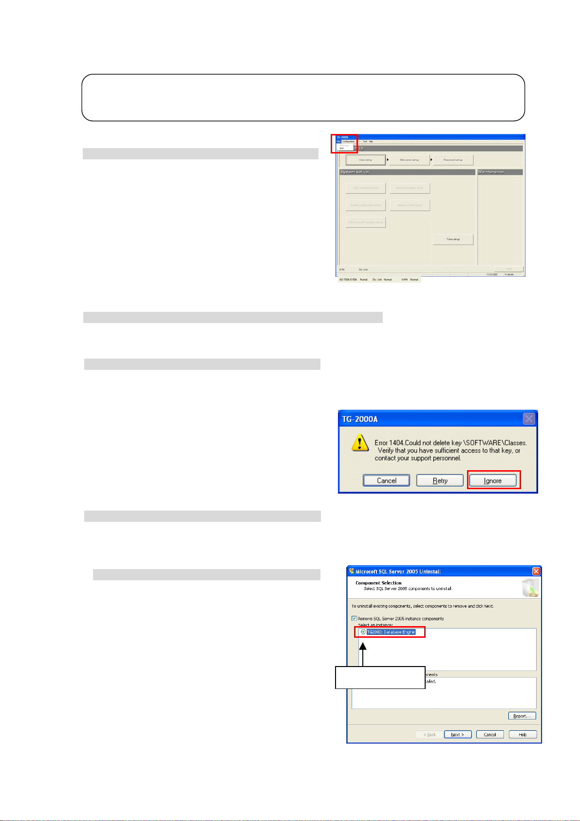
5.2.4 TG-2000A Uninstall (TG-2000A Ver.5.5* or later)
t
This section describes how to uninstall an installed “SQL Server 2005” and “TG-2000A” program.
Note:
• To uninstall TG-2000A Ver.5.1* or earlier, follow the uninstallation instructions in the Operating Manual tha
came with the TG-2000A.
Step 1) TG-2000A quit
1) Quit TG-2000A
Open the initial screen from the Management screen,
and select [File] - [End] from the menu bar.
A Quit confirmation window opens, so select the [OK]
button.
The TG-2000A program closes.
Quitting method
Step 2) Uninstall TG-2000A and SQL server 2005.
1) Open [Uninstall a program] or [Add/Remove Program] in the control panel.
Windows Vista: Open [Uninstall a program] (or [Programs and Features]) in the Control Panel.
Windows XP: Open [Add/Remove Program] in the Control Panel.
2) Uninstall TG-2000A.
Select the “TG-2000A” program.
Windows Vista: Click [Uninstall] to delete the program.
Windows XP: Click [Change/Remove] to delete the program.
If the window at right appears during uninstallation, click
[Ignore] to procede.
3) Uninstall SQL Server 2005.
Select the “Microsoft SQL Server 2005” program.
Windows Vista: Click [Uninstall] to delete the program.
Windows XP: Click [Change/Remove] to delete the program.
Select the components to remove.
Click on the radio button next to “TG2000A : Database
Engine” under “Select an instance” in the right screen,
and then click [Next].
Put the check.
26
Page 33
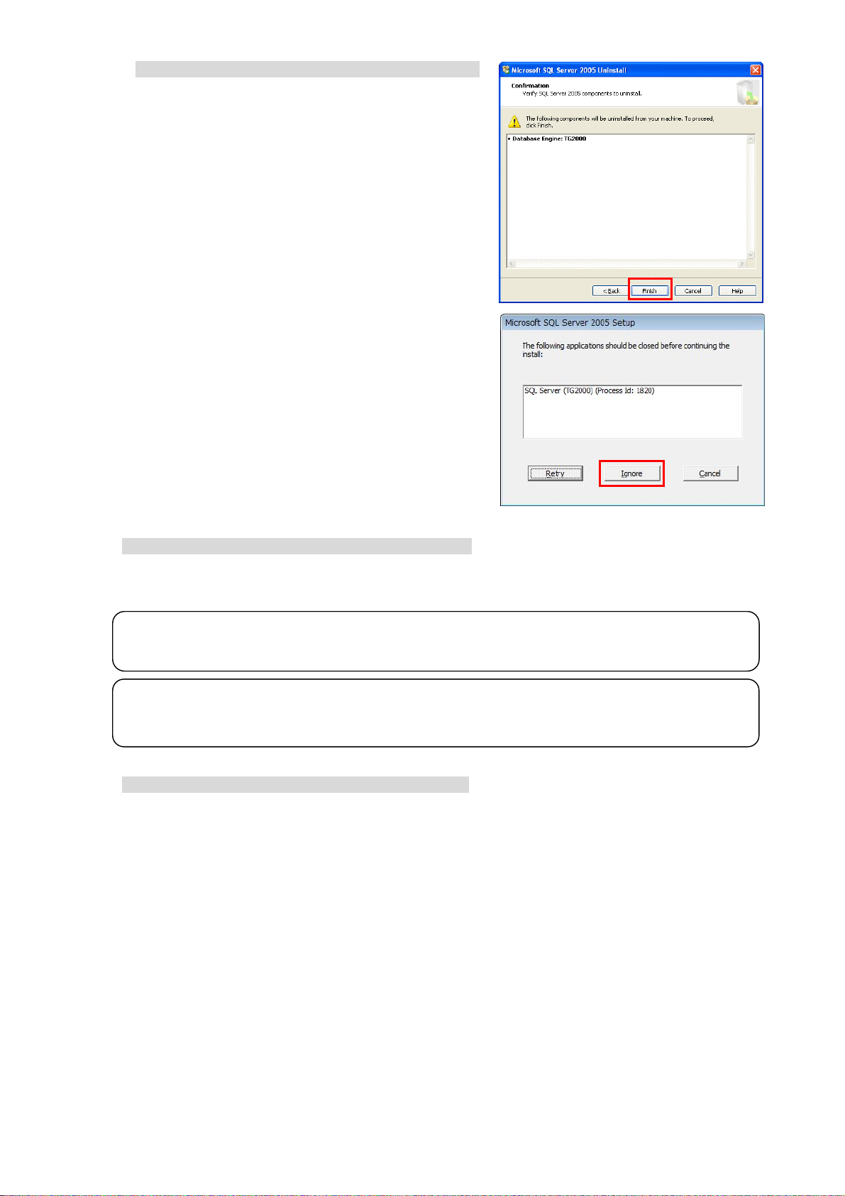
Confirm the setting.
Confirm that the correct program is selected, and click [Finish].
Uninstallation will begin and the window will close automatically
when uninstallation is complete.
If the window shown on the right appears, click
[Ignore] and proceed.
4) Uninstall Microsoft SQL Server Native Client.
Select Microsoft SQL Server Native Client, and click [Uninstall].
Note:
・There are some folders and files that cannot be uninstalled by taking the above steps, but that is normal.
・When SQL Server 2005 is used, it is not necessary to uninstall the program.
Important
・When uninstalling SQL Server 2005, only delete the files that are specified.
The program may become un-uninstallable if other files are deleted.
5) “Add/Remove Programs” ending
When program uninstallation ends, “Add/Remove Programs” ends.
27
Page 34
5.2.5 Adding files to the ignore list on the anti-virus sof tware (TG-2000A Ver.5.5* or later)
TG-2000A may be detected as a virus by the anti-virus program on the computer, if one is installed. When this
happens, TG-2000A’s EXE files need to be added to the ignore list to exclude them from being scanned.
After installing TG-2000A and the anti-virus program, add the following TG-2000A’s EXE files to the ignore list
for the Firewall or AutoProtect settings on the anti-virus software.
Folder Files to be added to the
ignore list
TG2000.exe
C:¥TG2000
C:¥TG2000¥Lib¥Exe
When installing an anti-virus software, it may ask the user to enter the names of the files to be included in the
ignore list. Follow the instructions that appear on the screen to add the above EXE files to the list.
How to add files to the ignore list depends on the anti-virus software. Refer to the Instructions Manual that
comes with the anti-virus software.
Important
・Where the EXE files are installed depends on the version of TG-2000A (Ver. 5.5* or later vs. Ver. 5.1*).
Refer to section 5.3.5 “Adding files to the ignore list on the anti-virus software (TG-2000A Ver. 5.1*)” when
adding the EXE files of TG-2000A Ver.5.1* to the ignore list.
TGSiteTool.exe (*1) (*1) When “Wide area” is set up
GMailSrv.exe
DbBkupTool.exe
G50Srv.exe
GChargeSrv.exe
GMultiSrv.exe
GTrendSrv.exe
GWHMSrv.exe
GcoolSrv.exe Total : 10 files
28
Page 35

5.3 TG-2000A Setup (TG-2000A Ver.5.1*)
r
p
5.3.1 Setup (TG-2000A Ver.5.1*)
This TG-2000A can be setup with the following two methods.
Method 1) New setup : Refer to section 5.3.2
Method 2) Version upgrade : Refer to section 5.3.3
The following shows the TG-2000A setup disk (CD-ROM) folder configuration and files. However, it
only describes the files to be run.
♦ New setup
[CD-ROM drive] ¥WindowsXP ¥Setup¥Step1¥SETUP.exe
¥Step2¥DbSetup.bat
¥Step3¥SetupTG.exe
♦ Version upgrade
[CD-ROM drive] ¥WindowsXP ¥Verup¥DbVerup¥DbUpdata.bat
¥TGVerup¥SetupTG.exe
[Reference] CD-ROM directory structure
¥Manual : Operation Manual, Simple operation manual (PDF file)
¥Tool : Air-conditioning charge calculation support tool (ChargeCalc.xls,
¥WindowsVista¥Setup : Set-up folder
¥WindowsXP : Set-up folder,Version-up folder
Readme.txt : Directory structure and setup precautions of this CD-ROM
AirConCharge.xls) and trend graph creation tool (TrendGraph.xls)
Test run check list creation tool (TestRunCheckSheet.xls)
Important
・Refer to section 5.2 “TG-2000A Setup (TG-2000A Ver.5.5* or later)” for how to set up the TG-2000A Ver.5.5* o
later.
Note
・Check that your computer meets the system requirements that are listed in “2.1 Requirements (system
recommendations)” before setting up or updating the system.
・Data that are recorded on TG-2000A Ver.5.20 or Ver.5.5* or later cannot be transferred to TG-2000A Ver. 5.1*.
Data on older versions cannot be transferred to newer versions of TG-2000A.
・If an antivirus software is installed on your computer, TG-2000A may be detected as a virus and the setu
procedures may not be completed properly. Add the TG-2000A’s EXE file to the “Ignore” list.
29
Page 36

5.3.2 Running TG-2000A Setup (New setup) (TG-2000A Ver.5.1*)
A
t
The TG-2000A setup is performed in three stages:
Step 1) MSDE setup (+ auto restart computer)
Step 2) Database setup
Step 3) TG-2000A setup (+ restart computer)
Note:
• Perform the 3 setup steps sequentially
• Be sure to log-in to Windows, using the Auto log-in name and password before executing the
set-up.
(It is necessary to execute the log-in with a log-in name having administrator rights.)
Caution:
•
lways quit all other programs (including resident programs) before installing TG-2000A.
. Otherwise, the TG-2000A will not operate properly.
Step 1) MSDE setup
Run the ¥WindowsXP¥Setup¥Step1¥SETUP.exe.
Check the confirmation message, and click the [OK] button.
* To cancel the setup, click the [Cancel] button.
Time required for setup: Approx. 2-3 min.
The screen shown on the right appears when the setup
is completed. Click the [OK] button. The computer is
automatically reset, and will be restarted.
Note:
• Restart the computer after completing the MSDE set-up.
Otherwise, Step 2 which follows may not be able to be se
up properly.
Step 2) Database setup
Run the ¥WindowsXP ¥Setup¥Step2¥DbSetup.bat.
A DOS window will open and the close 10 seconds
later when the process has finished.
30
Page 37

Step 3) TG-2000A setup
Run the setup program for TG-2000A. Perform the setup in accordance with the instructions on the
screen.
(1) Starting the setup program
1) Starting SetupTG.exe
Use Windows Start-Run to execute Run the
¥WindowsXP ¥Setup¥Step3¥SetupTG.exe
root directory of the Setup CD.
The setup start confirmation window appears. Read
and check the cautions which appear on the screen.
2) Check the displayed items and click the [Next] button.
If there is no problem with the cautions, click the [Next]
button to continue on to the next screen.
* Click the [Cancel] button to stop the setup.
(2) Read the license agreement
1) Read the license agreement and click the [Next] button.
The license agreement screens will be displayed one at
a time. Carefully read all of the agreement and check
that you agree with each item before selecting “It
agrees” and clicking [Next] to continue.
* If you cannot agree with the license agreement,
click the [Cancel] button and stop the installation of
TG-2000A.
(3) Check the installation folder
1) Check the location where the program is to be installed
and click the [Next] button.
Check the location where the program is to be installed.
If the location needs to be changed, set the new
location by clicking the [Browse] button.
After checking the installation location, click the [Next]
button.
* Click the [Cancel] button to stop the installation.
(4) Mode selection
1) Choose “Standard” or “Wide area” mode.
Choose the installation mode.
Standard: The mode which carries out
monitor/operation of one site
(Same function as up to Ver.4.50)
Wide area: The mode which carries out
monitor/operation of two or more
sites
(Usable function is limited)
2) Click the [Next] button.
After choosing the mode, click the [Next] button.
in the
Select
31
Page 38

(5) Installation start confirmation
1) Confirm that you want to start the installation and
select the [Next] button.
If the [Next] button is clicked the installation will start.
* Click the [Cancel] button to stop the installation.
(6) TG-2000A setup completion
1) Select [Finish] button
Click [Finish] button on installation screen.
2) After the installation is completed, restart the computer.
When the installation is completed, the program is
registered in the start menu and automatically run from
the next time the computer is started.
Store the CD is a safe place.
(7) Setting up the Firewall at TG-2000A startup
1) Configure the ignore list for the Firewall.
When starting up TG-2000A, a popup window will appear,
asking if you want to block the program.
Click [Unblock] to exclude the program from the Firewall.
*If the popup window becomes hidden behind the TG-2000A window, press
[Alt] and [Tab] simultaneously to bring up the window on the right,
and select Windows Firewall.
Note:
• Be sure to restart the computer
after installing TG-2000A.
• Mail tool is installed in both standard and wide area mode.
• Launch TG-2000A in the “Wide area” mode from the “Site change tool.”
Refer to “Chapter 4 The Usage of the Site Change Tool” in the manual (Wide area) for information on
“Site change tool.”
Windows Security Alert
32
Page 39
5.3.3 Upgrading the TG-2000A version (TG-2000A V er.5.1*)
The TG-2000A version is upgraded with the following four steps.
Step 1) TG-2000A quit
Step 2) TG-2000A uninstall (+ restart computer)
Step 3) Database version upgrade
Step 4) TG-2000A version upgrade (+ restart computer)
Maintenance Tip:
• These four steps must be carried out in the above order to upgrade the version.
The TG-2000A will not operate properly if the above order is not followed.
• The database should be backed up beforehand to prevent trouble. (Refer to Appendix 5.)
• Refer to sections 7.3 and 5.3.4 for details on steps 1 and 2.
• Quit all applications (including resident programs) other than MSSQL Server.
Step 1) TG-2000A quit
1) Quit TG-2000A
Open the initial screen from the Management screen,
and select [File] - [Quit] from the menu bar. A Quit
Confirmation window opens, so select the [OK] button.
The TG-2000A program closes.
* The TG-2000A program must be quit before the
version is upgraded.
Step 2) TG-2000A uninstall
1) Start up "Add/Remove Programs".
Start by clicking "Add/Remove Programs" in the Control Panel.
2) Uninstall TG-2000A
Start the "TG-2000A" program, and select [Change/Remove] to delete the program.
3) Restart the computer.
Since a program has been uninstalled, restart Windows.
Step 3) Database version upgrade
1) Start up DbUpdate.bat.
Execute ¥WindowsXP¥Verup¥DbVerup¥DbUpdate.bat
from the CD- ROM.
Required time: Approx. 10 seconds
The screen closes when the version upgrade
is completed.
33
Page 40
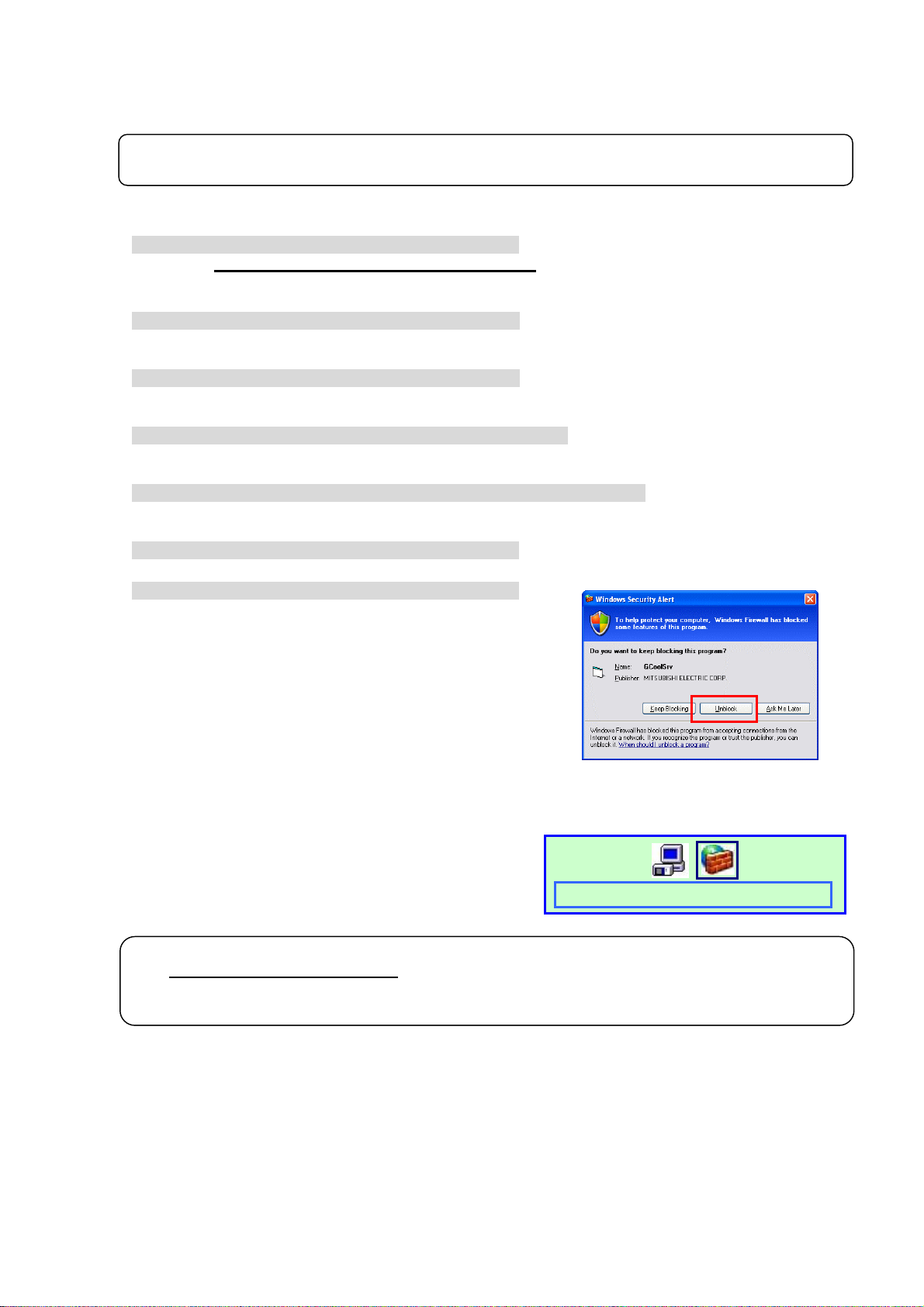
Step 4) TG-2000A version upgrade
Upgrade this TG-2000A application version. Read the on-screen instructions carefully, and
proceed with the setup.
* The procedures are the same as the new setup.
Note:
• Refer to step 3 in section 5.3.2 for details on the TG-2000A version upgrade procedures.
(1) Start up the version upgrade setup program.
1) Starting SetupTG.exe
Execute ¥WindowsXP¥Verup¥TGVerup¥SetupTG.exe
from the CD- ROM.
2) Check the displayed items and click the [Next] button.
(2) Read the license agreement
1) Check the displayed items and click the [Next] button.
(3) Check the installation folder
1) Check the installation folder, and then click the [Next] button.
(4) Check the start of installation
1) Check that the installation has started, and then select the [Next] button.
(5) Check the completion of TG-2000A setup
1) Select the [Finish] button.
2) Restart the computer.
When starting up TG-2000A, a popup window will appear,
asking if you want to block the program.
Click [Unblock] to exclude the program from the Firewall.
*If the program has already been excluded from the Firewall at the previous
setup, this window will not appear.
*If the popup window becomes hidden behind the TG-2000A window, press
[Alt] and [Tab] simultaneously to bring up the window on the right,
and select Windows Firewall.
Note:
• Be sure to restart the computer
• Check all of the settings, such as the user settings and charging system configuration, etc., on the
initial screen, and set if necessary.
after installing the TG-2000A.
Windows Security Alert
34
Page 41

5. 3.4 TG -20 00 A U nin st all (TG-2000A Ver.5.1*)
This section describes how to uninstall an installed “MSDE” and “TG-2000A” program.
Step 1) TG-2000A uninstall
1) Check to see if TG-2000A has ended
Check to see if the TG-2000A program has ended. If
it has not ended, end it.
* For a description of the ending method, see Chapter 7.
2) Start “Add/Remove Programs”.
Start by clicking Control Panel’s Add/Remove Programs.
3) Select “TG-2000A”, and click [Change/Remove]
button.
Select “Integrated centralized control software
TG-2000A” from the displayed programs, and click
the [Change/Remove] button. Uninstallation of the TG-2000A program begins.
Note:
• We recommend that you do not delete all the shared files.
• This uninstall cannot delete some folders and files. (Ex: C:¥TG2000)
4) “Add/Remove Programs” ending
When program uninstallation ends, Add/Remove Programs ends.
Step 2) MSDE uninstall
1) Start the SQL Server Service Manager
Start the “SQL Server Service Manager” by right-clicking the MSDE
icon on the taskbar.
MSDE icon
2) Stop all service
To stop all service, make your selection at the Service field and
click the [Stop] button.
3) End the SQL Server Service Manager
The “SQL Server Service Manager” window closes.
4) Close the MSDE icon
Right-click the MSDE icon on the taskbar and select [Exit]. The
MSDE icon is removed from the taskbar.
5) Start “Add/Remove Programs”.
Start by clicking on the Control Panel’s Add/Remove Programs.
6) Choose “MSDE”, and click the [Change/Remove] button.
Select “MSDE“ from the displayed programs, and click the
[Change/Remove] button.
Uninstallation of the MSDE program begins.
Note:
• This uninstall cannot delete some folders and files. (Ex: C:¥Mssql7)
• When MSDE is used, uninstall is unnecessary.
7) “Add/Remove Programs” ending
When program uninstallation ends, “Add/Remove Programs” ends.
35
Page 42
5.3.5 Adding files to the ignore list on the anti-virus sof tware (TG-2000A Ver.5.1*)
”
TG-2000A may be detected as a virus by the anti-virus program on the computer, if one is installed. When this
happens, TG-2000A’s EXE files need to be added to the ignore list to exclude them from being scanned.
After installing TG-2000A and the anti-virus program, add the following TG-2000A’s EXE files to the ignore list
for the Firewall or AutoProtect settings on the anti-virus software.
Folder Files to be added to the
ignore list
TG2000.exe
C:¥TG2000
C:¥WINDOWS¥system32
When installing an anti-virus software, it may ask the user to enter the names of the files to be included in the
ignore list. Follow the instructions that appear on the screen to add the above EXE files to the list.
How to add files to the ignore list depends on the anti-virus software. Refer to the Instructions Manual that
comes with the anti-virus software.
Important
・Where the EXE files are installed depends on the version of TG-2000A (Ver. 5.5* or later vs. Ver. 5.1*).
Refer to section 5.2.5 “Adding files to the ignore list on the anti-virus software (TG-2000A Ver. 5.5* or later)
when adding the EXE files of TG-2000A Ver.5.5* or later to the ignore list.
TGSiteTool.exe (*1) (*1) When “Wide area” is set up
GMailSrv.exe
DbBkupTool.exe
G50Srv.exe
GChargeSrv.exe
GMultiSrv.exe
GTrendSrv.exe
GWHMSrv.exe
GcoolSrv.exe Total : 10 files
36
Page 43

w
e
r
e
w
e
w
r
r
w
-
-
c
-
s
w
6. Part Names and Functions
6.1 Window Elements
The window displayed when the power is turned on and no system settings have been made is called
the Initial window. The Initial window has the following parts.
(The Initial window can be accessed from the menu bar with a password. For details, refer to section
6.3.)
Title bar:
Shows the title of the
windo
Menu bar:
Shows a list of
functions that may b
selected
System setting
group:
Sets the group info
mation, monitor dis-
play, charge calcula-
tion system, etc
Equipment state
display:
Displays the system
equipment as error o
normal.
Click the buttons to display the window associated with that feature. An example is shown below.
Title bar:
Display the title of
the windo
.
Message bar:
Display comments
about function display
and operation
Displays the operation contents of the [Next], [Back], [Cancel], and [OK] buttons on each setting screen.
Buttons Operation contents
[OK]
Advances to the setting screen with the confirmation contents on the preparation
screen determined not to have any problems.
Validates the contents set on this display screen to advance to the next setting screen.
[Next] Advances to the next setting screen.
Initial windo
System Configuration Options Control Windo
User setting group:
Sets valid/invalid for the
function, site name, and
password.
Maintenance group:
Function to correct th
charge calculation, etc.
Exit button:
Exits the Initial
and moves to the Manag
ment windo
Message bar:
Shows time, warnings,
and othe
Function display
operation setting
section:
Used to display/set the set
ting
contents.
Next,
and OK buttons:
Choose to end, return,
or cancel the setting of fun
tion display and operation
setting
Back, Cancel,
next,
[Back] Invalidates the contents set on this display screen to return to the last screen.
[Cancel] Invalidates the contents set on this display screen to shift to the initial screen.
37
Page 44
6.2 Basic Mouse Operation
r
First, use of the mouse as a pointing device will be explained. If a device other than a mouse is being
used, consult with the manual for that device.
The following is a list of terms used in describing mouse operations.
Click : This refers to pressing and releasing the button one time.
To use this function, click the button
Double Click : This refers to pressing and releasing the button twice in quick succession.
Drag : This refers to moving the mouse pointer on top of an object on the screen, pressing
and holding down the button to select the object, then, while holding the button down,
moving the mouse pointer, and the object, to a different location.
Keyboard : Primarily used when entering password, characters, or numerics.
6.3 Accessing Functions and Moving between Windows
The functions of the TG-2000A can be divided into two general categories.
1) Functions that monitor air conditioner operation status and control functions……Control window
2) Operation and system initialization and charge data maintenance functions (functions used to
accomplish functions in 1) above) ……Initial window
This section deals mostly with functions in category 2).
(1) Shift from the initial window to the control window
The following shows the procedure to shift from the initial window to the control window. Shift the
screen to the control window after completing the initial setting shown in Chapter 8.
During normal operation
Only the changed settings are transmitted to the
AG-150A/G-50A.
Normally shift to the control window using this method.
[Procedure]
1) Select [Finish] button.
Click the [Finish] button located on the lower right on the initial screen. With the above step, the
confirmation screen (asking whether or not to transmit the setting contents to the AG-150A/G-50A) is
displayed.
2) Select [OK] button.
Click the [OK] button to transmit the initial setting
contents to the AG-150A/G-50A.
* Click the [Cancel] button to return to the Initial window.
The start-up display screen is displayed after the
screen has been shifted to the control window. The
system information set or changed is transmitted to
each G-50A to enter upon the start-up processing.
It takes approximately 1 to 20 minutes
To transmit all settings
All of the settings are transmitted to the
AG-150A/G-50A.
Use this method to shift to the control window
when there is a difference in the system
information after starting up, or when copying a
set database to the site.
[Procedure]
1) Select [Configuration] - [All setting transmission]
in the menu bar.
Click the [Setting] in the menu bar on the control window to select [All setting transmission].
A screen for confirming whether to transmit all settings to the AG-150A/G-50A is displayed.
Screen of confirmation fo
transmitting set contents
Start -up display screen
to start-up.
All setting transmission window
38
Page 45
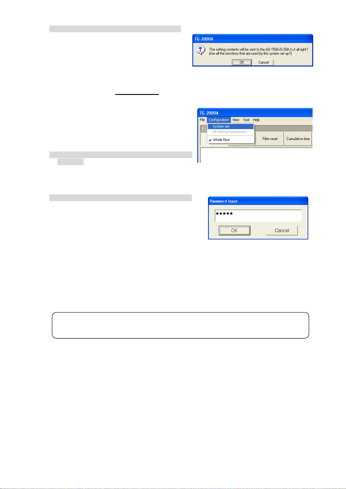
2) Select [OK] button.
Click the [OK] button to transmit all settings to the
AG-150A/G-50A.
* Click the [Cancel] button to return to the Initial window.
The start-up display screen is displayed after the
screen has been shifted to the control window.
The system information set or changed is
transmitted to each AG-150A/G-50A to enter upon the start-up processing.
It takes approximately 5 to 20 minutes
to start-up.
(2) Shift from the control window to the initial window
The control window shifts to the initial window when
the initial setting contents are changed or when the
charge calculation maintenance is performed.
[Procedure]
1) Select [Configuration] and then [System set] in the
menu bar.
Click the [Configuration] in the menu bar on the
control window to select the [System set]. The
password confirmation screen is displayed.
2) Enter the password
Enter the word “*****” in the password verification
box, then click the [OK] button. Doing so returns you
to the initial window.
There are 3 kinds of passwords.
Initialization password : All the items in the initial
window can be used.
The initial password is
“SYSTEM”.
Maintenance password : The initial window maintenance group and personal password can be
changed. This is also used as the password for "Charge set" on the
control window. The initial password is “Maintenance”.
For finishing TG-2000A on the management screen:
It is used to quit TG-2000A from the management screen.
The initial password is “tglogout”.
Maintenance Tip
• Manage the password to prevent unauthorized personnel from accessing the system. The
password can be changed.
Confirmation screen for all setting transmission
Display screen of Shift to setting screen
Password input screen
39
Page 46
<TG-2000A screen order 1>
Power On + Start
TG-2000A
System data
No system data
[User setup group]
Exit TG-2000A, shut
down the OS, and turn
the power off
Select [File]-[End]
button
[System setup group]
Select [Exit]
button
*Range described in this manual
Control screen window (Management)
(see separate management manual)
Password input
Select [File]-[End]
button
Return to Initial window
40
Page 47
User Set-up Set TG-2000A functions 50
Site Name Set-up Set the product name (site name) 61
Password change Changes the password to the 3 types of Initial window 61
Preparation for the AG-150A/
G-50A connection setting
Number of AG-150A/G-50A units
setting
AG-150A/G-50A IP address
setting
Preparation for System
configurations setup
Collecting AG-150A/G-50A data Collects the setting information for the AG-150A/G-50A during the
Unit configurations setup Sets the unit configurations in AG-150A/G-50A. 65
System structure of refrigerant
system
Function of each group Set indoor unit and ventilation groups. 69
Ventilation unit grouping Set ventilators and indoor unit groupings. 69
Option functions
Preparation for DIDO,AI,PI
controller set-up
DIDO controller set-up The information of group name, operation category, display and etc.
AI controller set-up Name, measuring range, warning information and etc. for AI controller
PI controller set-up The information of name, placement location, unit, pulse and etc. for PI
Option functions
Preparation for PLC for general
equipment setting
Number of PLC units Sets the number of PLC units. 75
PLC setting and initial setting Sets the IP address and initial state for each PLC. 76
Functional setting Sets the function used with each PLC. 77
Advanced setting (air conditioner
status monitor setting)
Advanced setting (peak cut
function setting) *
General equipment setting Selects the general equipment's functions and sets the name,
Option functions
Preparation of IC I/O signal
setting
General equipment setting Set the general equipment name, contact No. and display details. 81
Wizard name Primary settings contained in the activated window Reference page
Wizard name Primary settings contained in the activated window Reference page
Wizard name Primary settings contained in the activated window Reference page
Wizard name Primary settings contained in the activated window Reference page
Checks the step/caution display for the AG-150A/G-50A connection
setting.
Sets the number of AG-150A/G-50A units. 62
Sets the IP address for each AG-150A/G-50A.
It is possible to display the optional functions of the AG-150A/G-50A.
Wizard name Primary settings contained in the activated window Reference page
Verifies the order of system configuration settings and displays
warnings
initial setting.
Set refrigerant connections. 68
Wizard name Primary settings contained in the activated window Reference page
Set-up procedure and warning display for DIDO, AI and PI controller
can be confirmed.
for DIDO controller can be confirmed and saved
can be confirmed and saved.
controller can be confirmed and saved.
Wizard name Primary settings contained in the activated window Reference page
Verifies the PLC for general equipment setting steps and displays
warnings
Sets the AG-150A/G-50A to be monitored with each PLC. Sets this
when using interlocking control with air conditioners or the IC I/O
signal.
Sets the AG-150A/G-50A for peak cut operation with each PLC. Sets
this when the demand controller is connected to the PLC for general
equipment.
installation site and display details.
* This version is not compatible with the peak cut function.
Wizard name Primary settings contained in the activated window Reference page
Confirm the displayed steps and precautions for the IC I/O signal
setting.
62
62
64
64
72
72
73
74
75
77
77
78
80
41
Page 48

<TG-2000A screen order 2>
A
Power On + Start TG - 2000
System data
Select [Exit] button
* Range described in this manual
Control screen windows (Management)
Exit TG-2000A, shut down the
OS, and turn the power off
No system data
Select [File] - [End]
button
Password input
Return to Initial window
Select [File] - [End]
button
(see separate management manual)
[System setup group]
42
Page 49

Wizard name Primary settings contained in the activated window Reference page
Preparation for Monitoring screen
set-up
Set-up of model name Sets the model name of unit 83
Set-up of the number of floors,
and floor name (for sub-screen)
Plane view creation (for sub-screen) Create the plane view used with the floor screen for the sub-screen. 85
Set-up of the number of floors,
and floor name
Plane view creation Create a floor plane to be used in the floor window of the Management
Set-up relating a sub screen
plane view and a plane view
Set-up of floor name and
AG-150A/G-50A
Set-up of icon arrange and name Layout icons on the floor plane, and set names 88
Set-up of block Set groups in blocks 90
Option functions
• When using RS-485 WHM
Wizard name Primary settings contained in the activated window Reference page
Preparation for WHM set-up Check the WHM setting order and notes display. 92
Watt hour meter setting Sets the watt hour meter connection port and watt hour meter address. 92
Set-up for the name and the
maximum count value of WHM
Option functions
Preparation for meter setting Verifies the meter setting steps and displays warnings 94
Number of PLC units Sets the number of PLC for electric amount count units. 94
PLC setting and initial setting Sets the IP address and initial state for each PLC. 94
Meter setting Selects the meter to be used and sets the type name, installation site
Option functions
Preparation for Energy
monitoring set-up
Set-up for division mode Selects the apportioning mode for indoor and outdoor unit systems. 97
Relation between outdoor units
and watt hour meters
Electrical specification of outdoor
units
Relation between indoor units
and watt hour meters
Electrical specification of indoor
units
Charging blocks Set apportionment unit from the operational blocks. 101
Option functions
• When using RS-485 WHM
Currency unit Sets the currency unit used. 103
Air-Con-charge Sets the unit price, weekend charges and season charges, etc. 103
Standard charge Sets the standard (fixed) monthly charge. 104
Option functions
Basic charge setting (*1) Sets the basic charges in block and watt hour meter units. 106
Seasonal interval setting Sets the application of seasonal charges and the interval. 106
Weekly charge setting Sets the charge time zone and unit price, etc., for each day. 106
Annual charge setting Sets the charge time zone and unit price, etc., for specific dates in the
Meter unit price setting Sets the unit price for the gas, water and calorific value unit. 111
*1: Cannot be set with the power apportionment billing (manual electric amount input) function.
*2. Sets the unit price for meters other than the watt hour meter.
• When using PLC for electric amount count
Wizard name Primary settings contained in the activated window Reference page
Wizard name Primary settings contained in the activated window Reference page
Wizard name Primary settings contained in the activated window Reference page
• When using PLC
Wizard name Primary settings contained in the activated window Reference page
Verifies the order of monitoring screen settings and displays warnings 83
Set the number of floors and floor names for the sub-screen. 84
Sets the number of floors and floor name. 86
screen (control window)
Set the relation of floor screen for sub-screen and floor screen. 87
Set floor and AG-150A/G-50A assignment 87
Sets the WHM name, installation location, and maximum integrated
value.
and pulse units.
Verifies the order of billing settings and displays warnings. 96
Assigns outdoor units to watt hour meters. 98
Set value of crank case heater for outdoor units. 99
Assigns indoor units to watt hour meters. 100
Set indoor unit capacity and power input. 101
year.
86
93
95
108
43
Page 50
<TG-2000A screen order 3>
A
Power On + Start TG - 2000
System data
Select [Exit] button
* Range described in this manual
Control screen windows (Management)
Exit TG-2000A, shut down the
OS, and turn the power off
No system data
Select [File]-[End]
button
Password input
Return to Initial window
Select [File]-[End]
button
(see separate management manual)
[System setup group]
[Maintenance group]
44
Page 51

Option functions
Wizard name Primary settings contained in the activated window Reference page
Preparation for energy saving
and peak cut
Set up of the Watt hour meter for
energy-saving/peak cut
Peak cut set-up Peak cut setting. *Only when using peak cut. 115
Option functions
Wizard name Primary settings contained in the activated window Reference page
Preparation for night mode set-up Verifies the steps and precautions for night mode set-up. 120
Night mode set-up Sets the outdoor unit for the night mode and the time to carry
Option functions
Wizard name Primary settings contained in the activated window Reference page
Preparation for
system-changeover set-up
System-changeover set-up Sets the main group of the refrigerant system block for carrying
Wizard name Primary settings contained in the activated window Reference page
Time set-up Sets the current time. 124
Option functions
Wizard name Primary settings contained in the activated window Reference page
Maintenance of charge data
(Present value monitor)
Maintenance of charge data
(Meter maintenance)
Maintenance of charge data
(Unit)
Option functions
Wizard name Primary settings contained in the activated window Reference page
Operation / electric power amount
data monitor
Option functions
Wizard name Primary settings contained in the activated window Reference page
Remedial apportioning setting Remedial apportioning can be tentatively performed when charging
Option functions
Wizard name Primary settings contained in the activated window Reference page
Billing comparison data
maintenance
Option functions
Wizard name Primary settings contained in the activated window Reference page
• Energy saving and peak cut setting
Verifies the steps and precautions for energy saving and peak cut. 112
WHM for energy saving and peak cut setting 112
out the night mode for each AG-150A/G-50A.
Verifies the steps and precautions for system-changeover
(automatic cooling/heating switching) set-up.
out System-changeover, etc., for each AG-150A/G-50A.
Data for the last 62 days from the watt hour meter, indoor units, and
outdoor units can be viewed and edited.
(Also, current values for watt hour meters can be monitored.)
Watt hour meter data from the last 62 days can be viewed and edited. 133
Data for the last 62 days from indoor units and outdoor units can be
viewed and edited.
Operation data stored in AG-150A/G-50A can be monitored and
saved.
Also, electric power amount data stored in PLC(or AG-150A/G-50A)
can be monitored and saved.
trouble occurs.
The data used to compare apportioned charges when the
AG-150A/G-50A or PLC fails can be cleared.
120
121
121
129
140
135
137
151
Billing trial operation This function enables trial operation of the power apportion billing.
A state similar to the actual charge calculation can be calculated and
confirmed in one day.
45
182
Page 52
t
7. Initial Startup and Shutdown
7.1 Before Startup
Please confirm the following items before starting the TG-2000A application.
(1) A test run of the air conditioning system has been completed.
(2) Check that the computer, hub, AG-150A/G-50A, power supply unit, and air conditioner power are
turned on.
(3) All PC hardware and cables have been connected and the proper software installed.
(4) “Date and time” setting are correct.
7.2 Startup
Start the integrated centralized control software TG-2000A
application.
Follow these steps to startup the TG-2000A application.
[Procedure]
1) Restart Windows
When Windows(OS) restarts, the user automatically logs on
and the TG-2000A program starts. When the startup process
begins, the setup screen is displayed.
* When Windows(OS) restarts, the integrated centralized
control software TG-2000A application starts
automatically.
After the startup screen is displayed, the behavior of the
application depends on the existence of System Settings
data.
Case 1: Without System Settings data: (the first startup)
The initial screen is displayed. Start with Chapter 8
“Changing System Settings”
Case 2: With system setting data
After the system has been set up once, turning on the
power brings up the Management window, and the
startup process begins immediately.
The startup process takes some time (approx. 10 to 20
minutes).
To change the initial settings, go to the initial window.
Refer to the procedure in section 6.3 “Accessing
functions and moving between windows”.
Maintenance Tip
• For safety reasons, make a thorough check of all equipment and connections.
• The "detach" and "attach" shortcut icons on the desktop screen are for servicing. Do no
use these during normal operations.
• Launch TG-2000A in the “Wide are” mode from the “Site change tool.”
Refer to “Chapter 4 The Usage of the Site Change Tool” in the manual (Wide area) for information
on “Site change tool.”
• The warning message may appear depending on the the security software when the
firewall is activated. Set the TG-2000A software to “Always connected”.
Desktop screen
Startup screen
Initial window
46
Page 53

7.3 Shutdown
A
t
k
TG-2000A Shutdown
Follow these steps to shutdown TG-2000A.
[Procedure]
1) Select the End option in the File menu in the Menu Bar
Always end the application before turning off the power.
Shutdown is done from the initial window.
Select the File menu in the Menu Bar and select the End
option.
* To switch to the Initial window, refer to section 6.3.
2) Select [Exit] button.
The shutdown confirmation dialog box appears asking to
confirm this action.
After verifying the content of the dialog box, click the [Exit]
button to exit the application.
* Click the [Cancel] button to return to the Initial window.
Maintenance Tip
• Always exit the TG-2000A application before
turning off the PC. Failing to do so could result in
damage.
• Note that when the TG-2000A application is
exited, the functions used stop. When the charge
calculation function (only for constant operation)
is used, set the operation mode to TG-2000
24-hour continuous operation.
• If the message "There is data which has no
been transmitted to AG-150A/G-50A. Please end
after choosing "Cancel" button, choosing a
"Finish" button and transmitting data." appears
on the End warning display screen, always clic
"Cancel", and click the "Finish" button on the
initial window, and then transmit the setting
changes to the AG-150A/G-50A before ending.
Shutting down the OS
Shut down the Windows(OS) after verifying that the TG-2000A application has been exited. Turn off
the PC after shutting down the OS.
* Please see the OS or PC owner’s manual for procedures on shutting down the OS and turning off the PC.
End the application
Shutdown verification
End confirmation window (with warning)
47
Page 54

w
t
p
p
p
t
-up
p
8. System Setting Procedure
8.1 System Setting Screen
The following is an explanation of the items found in the System Settings window.
User Se
System Se
Function group Function Operation details
[User Set-up group]
[System Set-up
group]
[Maintenance group]
Note:
• Refer to Chapter 9 for the maintenance group items.
• The set items that are displayed depend on the functions of theTG-2000A purchased.
grou
grou
u
Initial windo
User set-up Allow or disallow certain functions
Site name set-up Set the building name
Password set-up The password can be changed
AG-150A/G-50A
connection set-up
System configuration
set-up
DIDO, AI, PI controller
set-up
PLC for general equipment
set-up
Monitoring screen set-up Executes the model name setting, plane drawing creation, group icon
Measurement meter set-up
(Watt hour meter set-up)
Energy monitoring set-up Set the system billing function
Charge set-up Sets the basic charge, seasonal/interval, weekly charge, and annual
Energy saving set-up Sets the control operation, etc., for energy saving operation.
Night mode set-up Sets the night mode target and time.
System-changeover set-up Sets the refrigerant target and changeover mode, etc., for
IC I/O signal set-up Sets the general equipment connected to the IC I/O signal, etc.
Time set-up Set the current time. Each AG-150A/G-50A time can be monitored.
Maintenance of charge
data
Operation amount/electric
amount data monitor
Remedial apportioning
setting
Maintenance of comparison
data for energy monitoring
Test run for energy
monitoring
Sets the number of AG-150A/G-50A units connected and the IP address.
Sets the system configuration, group, interlocking unit, etc.
Sets the each item of DIDO, AI, PI controller.
Sets the number of PLC units, and general equipment functions and
names, etc.
arrangement, etc.
Sets the number of PLC units, and meter type, name and pulse unit, etc.
(Set the watt hour meter serial port and watt hour meter address)
charges, etc.
automatically changing between cooling and heating.
Proportional billing information can be revised.
The WHM present value can be monitored or changed (overwritten).
The AG-150A/G-50A operation amount, PLC measurement/power amount
data can be monitored and overwritten.
Remedial apportioning can be tentatively performed when charging trouble
occurs.
The data used to compare apportioned parameters when the
AG-150A/G-50A or PLC fails can be cleared.
Operation can be tried to confirm that the charge function is operating
correctly.
Maintenance grou
48
Page 55
Displays the operation contents of the select buttons on each setting screen.
r
Buttons Operation contents
[OK]
[Next] Advances to the next setting screen.
[Back]
[Cancel] Invalidates the contents set on this display screen to shift to the initial screen.
Validates the contents set on this display screen to advance to the next setting screen.
(Advances to the next setting screen if it is the preparation screen.)
Invalidates the contents set on this display screen to return to the last screen.
8.2 System Setting Procedure
The following is an explanation of the System Settings performed at the Initial window.
When no System Settings exist
User setting group
Step 1: "User set-up"
Step 2: "Site name set-up"
Step 3: "Password set-up"
System setting group
Step 4: "AG-150A/G-50A connection set-up"
Step 5: " DIDO, AI and PI controller set-up" *5
Step 6: "System configuration set-up"
Step 7: "PLC for General Equipment set-up"
*1, *2, *4
Step 8: "Monitoring screen set-up"
Step 9: "
Step 10: "
Measurement meter set-up" *3
Energy monitoring set-up" *3
Step 11: "Charge set-up" *3
Step 12: "Energy-saving set-up" *4
Step 13: "Night mode set-up"
Step 14: "System-changeover set-up"
Step 15: "IC I/O signal set-up" *2
Step 16: "Time set-up"
*1: This must be set when using the general equipment.
*2: These items must be set when using the general equipment (IC I/O signal).
*3: These items must be set when using the power apportionment billing function. The " Measurement
meter set-up" step is not required when using only the power apportionment billing (manual electric
amount input) function.
*4: This item must be set when using the energy saving or peak cut functions.
*5: This item must be set when using the DIDO, AI and PI controller.
* Even if the AG-150A/G-50A is not actually connected, it is possible to set it in advance as long
as information such as system configuration, etc. is available.
Caution:
• If the settings are done out of order, some items will not be available and others will have to
be set again.
• Time set-up and Site name set-up are only performed when necessary. Check the time fo
each AG-150A/G-50A with “Time set-up”, and set the time when necessary. For "Time
set-up" check the time of each AG-150A/G-50A and PLC, and set the time if necessary.
If the time is set incorrectly, the function does not work properly.
• Even if the operation settings are unclear, set all of the system setting items that appear.
When System Settings exist
Make any changes to the settings.
Note:
• Changing certain settings affects the status of other settings.
• User set-up in particular affect other settings and functions.
• Changing the settings on the left affects the settings on the right.
Change and setting items Items that must be confirmed (affected items)
1 "System configuration set-up"
2 "PLC for General Equipment set-up" "Monitoring screen set-up"
3 "Monitoring screen set-up" "Energy monitoring set-up"
" Measurement meter set-up "
4
(“Watt hour meter set-up”)
"Monitoring screen set-up", "Energy monitoring set-up"
“Night mode set-up”,”System-changeover set-up”
"Energy monitoring set-up", "Energy saving set-up"
49
Page 56

A
r
p
After setting all items on the initial screen and
selecting the [Finish] button, the confirmation
message [All the contents of a setting are
transmitted to AG-150A/G-50A. Is it all right?]
appears. Select [OK] and transmit the latest
setting information to the AG-150A/G-50A.
Note:
• If all settings must be transmitted due to a difference in the
system information, etc., carry out "To transmit all settings" in
section "6.3.(1) Shift from initial window to the control window".
8.3 User Set-up
Use these settings to allow or disallowTG-2000A general
operations, printer, charge (billing), and external I/O functions.
Activating TG-2000A Functions
[Procedure]
1) Click the User set-up button
From the Initial window, click the User set-up button
in the User set-up group. The User set-up window appears.
2) Select the [Finish] button after setting all items
Click the [Finish] button after setting all items in
the User setting windows 1 through 4.
* The settings will be invalidated when the [Cancel] button is clicked.
Note:
・The following folder cannot be specified for "Backu
folder name" of "Backup setting".
x:¥Windows , x:¥WinNT , x:¥Documents and Settings ,
x:¥Program Files , x:¥ProgramData ,
x:¥Users , and C:¥ (“x” shows the drive letter. )
Changing the User setting window
[Procedure]
1) Select [User set-up *] button.
Click the [User setting 1], [User setting 2],
[User setting 3], or [User setting 4] button.
Note:
・Click “Go to the user setting *” to switch between the
user setting windows.
・The settings in each window will be stored even afte
switching to another user setting window. After setting
all the necessary items, click “Finish.”
[OK] button
The group information,
etc., is transmitted to the
G-150A/G-50A.
User setting 1 window
User setting 2 window
50
Page 57

8.3.1 General Operation
r
Set the schedule and summer time and turn on and off the filter sign automatic display function
(Range restrictions of setting temp.).
Setting general operation options
[Procedure]
1) Click the option button.
Set the "Schedule set-up", "Summer-time set-up", "Filter sign" "Range restrictions of setting temp.",
"Night mode set-up", "Auto change over set-up" and "Sub screen function (floor division)" under
General operation. Click on the option button for the details to be set.
Item Set value Details
Schedule Set-up
*1
Summer Time
Set-up
Filter sign
Range
restrictions of
setting temp.
Automatic
output
abnormality
history
*2
Night mode
set-up
System-change
over set-up
*3
Sub screen
function
(floor division)
Off
(Deactivate)
(Default)
On (Activate)
Off
(Deactivate)
On (Activate)
(Default)
Off
(Deactivate)
On (Activate) Automatically display. (Default)
Off
(Deactivate)
(Default)
On (Activate) Temperature limit range is set
Off
(Deactivate)
(Default)
On (Activate)
Off
(Deactivate)
(Default)
On (Activate)
Off
(Deactivate)
(Default)
On (Activate)
Off
(Deactivate)
(Default)
Divide
(4 sections)
Divide
(6 sections)
Turns the scheduling function
off.
Turns the scheduling function
on.
Do not automatically adjust the
AG-150A/G-50A for summer
time.
Automatically adjust the
AG-150A/G-50A for summer
time. (Automatic monitors take
place at 04:17 AM)
Do not automatically display.
Temperature limit range is not
set
Do not automatically output
Automatically output once a day
Choose from “Only data of
yesterday” and “All data”.
Turns the night mode function
off.
Turns the night mode function
on.
Turns the system-changeover
function off.
Turns the system-changeover
function on.
Turns the floor division function
off.
Turns the floor division function
on.
Turns the floor division function
on.
General operation set up
*1: Refers to the annual/weekly schedule.
*2: The file output default can be changed with “C:¥TG2000¥ErrorLog¥”
*3: System-changeover is the function that automatically switched between cooling and heating modes of Y series
(cooling/heating change over type).
Note
• The floor layout that was created for the TG-2000A cannot used with the AG-150A. Likewise, the floo
layout that was created for AG-150A cannot be used with the TG-2000A.
51
Page 58

y
Note:
• When filter sign automatic display is deactivated, the filter status is not reflected automatically even
when the filter sign window is selected. When the View filter button is clicked, the filter status is
reflected.
• To use the Schedule Set-up, it is necessary to register the license number of the annual/weekl
schedule separately with the AG-150A/G-50A. When the license is not registered with the
AG-150A/G-50A, it only possible to use the weekly schedule function of the AG-150A/G-50A. In this
case, the schedule setting made from the integrated centralized control softwareTG-2000A is
invalidated, resulting in operation failure.
• The set temperature range limit can be reflected onto only the ME remote controller and individual
browser. (This function may not be available from the MA remote controller, depending on the model
of indoor units connected to the system.)
8.3.2 Reliability Function
Turn on and off the automatic reboot function as backup and the database backup function.
Setting automatic reboot and database backup function
[Procedure]
Automatic reboo t s e tting
1) Click the option button
Use the option button to select the Automatic Reboot function.
Automatic reboot setting
Do not automatically reboot:Does not automatically reboot.
(Default)
Automatically reboot(Days) :Automatically reboots on
the selected day
Automatically reboot(Weekly) :Automatically reboots on
the selected day of a week
2) Select the reboot interval using the “/ ” buttons.
When automatic reboot was set to On, select the automatic
/
reboot day using the “
” buttons. The setting range is the 7th
thru 31st day after booting. The initial value is the 31st day.
3)Automatically reboots by Weekly specification
When “Weekly automatic reboot” was set to On, select the day of a week.
Only one day of the week can be selected.
Backup setting
4) Click the option button
Use the option button to select the Database Backup function.
Backup setting
Off (Deactivate) : Do not back up the database. (Default)
On (Activate) : Back up the database.
5) Set the output folder.
When database backup was set to On, set the database folder to be backed up using the Browse
button. The initial value is “C:¥TG2000¥databackup”.
* Set the folder to be backed up to an HDD drive different from the C: drive.
Maintenance Tip
• Manually restart theTG-2000A application and Windows(OS) on a regular basis (once a
week). (Perform the restarting operation during the period from 08:00 to 21:45.)
* Recommendation: Perform manually without automatic rebooting.
Reliability Function Settings
window
52
Page 59

play
Note:
• When Windows(OS) is used continuously without restarting, system errors may accumulate. Thus
it is necessary to restart both TG-2000A and the Windows(OS).
• The automatic restart function serves to insure that the system restart is done on a regular basis.
If there is an error during the automatic restart, the system must be restarted manually. Since
there is a possibility of the error not being detected, it is recommended to periodically restart the
system manually.
• When automatic reboot is set to [ON], Windows reboots automatically at 06:35 on the 7th to 31st
day after booting. (The number of days depends on the set value.)
• The system configuration, history, and charge data databases are backed up. The trend and
dis
characters databases are not backed up.
8.3.3 Connection Setting
Set whether each device is connected on the User setting 2 window.
Connection settings
Setting connector options
[Procedure]
1) Click the option buttons
Use the option button to select the printer and WHM connection.
Available printer options are ON or OFF.
The validity of the billing settings and energy saving functions are reflected with the watt hour
meter/meter settings.
Item Set value Details
Printer connection
WHM/Measurement meter
connection
PLC for General
Equipment
Note:
• Data cannot be printed if this option is OFF.
• Install the printer driver and confirm that printing is possible beforehand.
Off (No connection)
(Default)
On (Connection) Turns the printing function on.
OFF (No connection)
(Default)
PI controller (MCP)
PLC
Serial
OFF (No connection)
(Default)
ON (Connection) The general equipment can be connected.
Turns the printing function off.
The watt hour meter/measurement meter cannot be
connected.
The watt hour meter/measurement meter can be
connected with an PI controller.
The measurement meter can be connected with a
PLC connection.
The watt hour meter can be connected with an
RS-485 connection.
The general equipment cannot be connected.
53
Page 60
8.3.4 Energy Saving /Peak Cut and IC I/O Sigmal/Interlocked Control Setting
t
Set the energy saving settings/peak cut function and
trend functions
Set whether the other functions are valid.
[Procedure]
1) Click the option button.
Select the energy saving/peak cut function settings
with the option button.
Item Set value Details
Energy saving/
peak cut
function *1
IC I/O signal
/interlocking
control functi o n
*2
Deactivate Energy saving/peak cut function disabled. (Default)
Energy saving Energy saving function enabled.
Peak cut (WHM) Peak cut function with WHM enabled. (Including energy saving function)
Peak cut (PLC) Peak cut function with demand controller connected to PLC (Including
energy saving function)
Deactivate Do not connect general equipment to IC I/O signal. (Default)
Interlocking control will not be performed on PLC for general
equipment.
Activate Connect general equipment to IC I/O signal for monitoring and operation.
Interlock control will be performed on PLC for general equipment.
Peak Cut, etc. functions
*1: There are two types of peak cut functions.
WHM: The power rate is read in from the electric amount count PLC or PI Controller, and the level is
PLC for demand input: A demand controller is connected to the PLC for demand input, and the PLC for demand
*2: When interlocking control, such as stop of the air conditioner, is performed on PLC for general equipment while the
general equipment (e.g. card key) is ON, “Activate” must be set.
Note:
• The "Peak cut function" cannot be selected when the PLC watt hour meter or PI Controller, is no
connected.
• The "Energy saving function" and "Peak cut function" license numbers must be registered in the
G-50A to use the energy saving function and peak cut function.
judged by the AG-150A/G-50A.
input which receives contact signals according to the level notifies the AG-150A/G-50A.
8.3.5 Energy Monitoring Related
Follow these steps to energy monitoring functions On or Off, automatically print air conditioning
charges, and set printing options.
Energy monitoring function s O n or O ff
[Procedure]
1) Click the option button
Use the option button to select Energy
Monitoring function, Automatic Air Conditioning
Charges Print, or Air Conditioning Charge Output
Processing function setup.
Energy monitoring related
54
Page 61
Item Set value Details
function
G-50A system
Energy monitoring
automatic output
Energy monitoring
output format
WHM/Measurement
meter connection
The order of char ge
display
Charge for FU
Off (Deactivate)
(Default)
On (Activate) Activates Energy monitoring related
Off (Deactivate) Deactivates always connected to G-50A system function. Always connected to
On (Activate)
(Default)
Off (Deactivate)
(Default)
Printing Print Energy monitoring automatic printing information
Exporting file Automatically output air conditioning charge result as a file.
Printing and exporting
file
Standard (Default) Output standard items
Items for every unit Output air conditioning charge summary for each unit
Items for every unit
price for charge
Details for every unit
price for charge
No connection
(Default)
Connection Charge calculation function with WHM connected
Block No. order
(Default)
Alphabetic order The charges are displayed in alphabetic order.
Off (Deactivate)
(Default)
On (Activate)
Deactivates Energy monitoring related Energy monitoring
Activates always connected to G-50A system function.
(Recommended mode)
Do not automatically print air conditioning charges.
automatically.
*1
Automatically print and automatically output air
conditioning charges as exporting file a file. *1
Output air conditioning charge summary for each unit price
Output detailed air conditioning charge summary for each
unit price
Charge calculation function without WHM connected…
Manual electric amount input
The charges are displayed in the order of the registered
block numbers.
Deactivate apportioning billing system for OA processing
unit (FU).
Activate apportioning billing system for OA processing
unit (FU).
Charge for A/ K
control unit
*2
Off (Deactivate)
(Default)
On (Activate)
Deactivate apportioning billing system for A-control and
K-control units.
Activates apportioning billing system for A-control and
K-control units.
A-controller
*3
AOC/AIC
Same power supply
System is configured in the way that the A-control outdoor
and indoor units are powered from the same power
source to which a single watt-hour meter is connected.
AOC/AIC
Separated power supply
System is configured in the way that the A-control outdoor
and indoor units are powered from different power
sources to which separate watt-hour meters are
charge parameter
*4
Rounding off
Process
*5
connected.
Off (Deactivate)
(Default)
On (Activate) Automatically output charge parameter. *2
Before calculation charge
(Default)
After calculation charge Charges are calculated without the apportioned electric
Do not automatically output charge parameter. Automatic output of
(Monthly or Daily output)
Charges are calculated after the apportioned electric
power is rounded off.
power being rounded off, and the result is rounded off.
*1: The default file output can be changed with [C:¥TG2000¥Chargefile¥].
*2: Not all functions are supported by all units.
55
Page 62

*3: Selectable only when the “
t
“Charge for A/K control unit” setting is set to “
The value for “
AOC/AIC Same power supply” is calculated by factoring the amount of indoor fan
WHM/Measurement meter connection” setting is set to “Connection” and the
Activate.”
operation in to figure out the apportioned electric power for the A-control outdoor unit because the indoor
and outdoor units are both powered from a single power source.
On the other hand, when calculating the value for “
AOC/AIC Separated power supply,” the amount of
A-control fan operation is not factored in to figure out the apportioned electric power for the A-control
outdoor units since these indoor and outdoor units are powered from separate power sources.
The amount of apportioned electric power for the A-control outdoor units in the system using TG-2000A
Ver. 5.20 or earlier, is calculated in the same way (the amount of indoor fan operation is not factored in).
To calculate the apportioned electric power in the same way, select “
AOC/AIC Separated power supply.”
*4: The default file output can be changed with [C:¥TG2000¥ChargeParameter¥].
A folder “¥yyyy (year) ¥mm(month)¥” will be created in the folder that is selected in the user
setting 2 window. The charge parameter will be saved in this folder.
*5: In the system using TG-2000A Ver.5.20 or earlier, charges are calculated without rounding off
the apportioned electric power. To calculate the apportioned electric power in the same way as the
earlier versions, select “After calculation charge.”
Note:
• When the printer is not connected, it is unable to set the printing for the "Energy monitoring auto
output".
• When thisTG-2000A is not provided with the "Charge function", this screen is not displayed. In
order to use the charge function, please contact a Mitsubishi official sales office or supplier.
• The charge function can be set only for No WHM connected, PLC connected or RS-485
connected (Manual electric amount input, electric amount pulse count or direct read in of power
value into computer).
• The filename is “(Month)-(Year) *.csv”. (*: B=Block units, W=WHM units)
(The year and the month when the charge calculation is performed are shown.
Eg. When the calculation for September, 2005 is performed at the end of the month, the file name
will be “09-2005B.csv”.)
• When using the "Charge calculation function", it is necessary to register the license number of
the "Charge calculation function" separately with the AG-150A/G-50A. If the license is not
registered with the AG-150A/G-50A, the charge calculation function will not operate properly. It
is necessary to register the "Charge function" license with all AG-150A/G-50A units controlled by
theTG-2000A.
• In regard to the output format, the details for each unit, etc., are compatible even with the
designated settlement date calculations from this Ver. 4.30. Note that the output format differs
from previous versions.
Note: (The end method of a user setup .)
Click the [Finish] button when finished setting User setting 1 through User setting 4. The details se
on User setting 1 through User setting 4 will be saved, and the initial window will appear.
If [Cancel] is clicked, all of the details set on User setting 1 through User setting 4 will be deleted, and
the initial window will appear.
56
Page 63

8.3.6 Setting the Warning Sound
Make the setting for the warning sound on User setting 3 window.
(User setting 4 on TG-2000A Ver.5.10 or earlier and Ver.5.20)
a)
b)
c)
User setting 3 window
[Operation Method]
1) Make the following settings with the option button
Enable or disable the warning sound and select the play mode.
Item Setting Content
a)Warning sound upon
error detection
b)Repeat Input This setting is available only when “Beep” or “Plays wav
c)Repeat button - Use this button to check the warning sound.
Does not play
(Default)
Beep Upon error detection, the warning sound that is selected
Plays wav file Upon error detection, the wav file that is selected in this
Warning sound will not sound, nor the pop up window
will appear on the screen upon error detection.
on the control panel will sound once, and the pop up
window will appear on the screen.
setting window will be played once, and the pop up
window will appear on the screen.
file” is selected. When this function is enabled, either type
of the selected warning sounds will be played repeatedly.
Notes
・Playback of warning sounds and pop up window display are available only on the TG-2000A’s management
screen.
・If another error is found in another system after the warning sound is turned off or the pop up window is closed,
a warning sound will sound again and the pop up window will reappear.
Pop up frequency:Every error
Warning alarm frequency:Every error code except for the one set to OFF
・A PC that is not equipped with a speaker will not play the warning sound.
・The sound volume depends on the Windows settings.
・The sound volume and quality depends on each PC. Change the setting to turn up the volume of the
warning sound.
・The sound quality of the general warning sound (beep) will depend on the settings on the control panel, but
the sound quality of the wav file will not.
57
Page 64

o
8.3.7 Trend setting
Set the trend functions.
Set whether the other functions are valid.
[Procedure]
1) Click the option button
Select the trend function settings with the option button.
Item Set value Details
Trend
Deactive
(Default)
Active
Trend function deactivated.
Trend function enabled. *2
Temperature, on/off, mode, error trend function:
Sampling interval setting:
Trend function for AI controller:
Effective/nullity (Default)
Sampling interval setting :
Select the output time
4:40(default),0:20 *3
File output target
Specify the output files *1
Output format
Previous data format : Does not use graph function
Graph function associated format: Use graph function
Activate/deactivate (Default)
Select from 2, 5, 10, 15, 30, 60 (Default)
*Effective when connecting with a measuring meter.
Select from 5,10,15,30,60 (Default)
Other functions (1)
*1: The file output default can be changed with "C:¥TG2000¥TrendData¥".
*2: The temperature, on/off, mode trends are available only for the indoor unit group, and include A control and K control.
*3: When selecting "0:20," trend data of AI controller does not automatically output. Select 4:40 (Default)" for automatic output.
Note:
• To use the trend function for the temperature, on/off, and drive mode, block settings for the
control target indoor unit groups need to be set.
• If the trend function is not required, the function should be "Disabled" to reduce the operation
load.
• The electric amount value and power apportion value trends are automatically judged according
to the connection or presence of functions.
• When the trend output function is used, check that the CSV files are automatically output.
• Those automatically output trend data CSV files are kept in the target output folder for two years.
The files in the monthly folder are deleted after two years have passed. Periodically back up data t
external memory storage device.
• How long the data are kept and how often the data are collected depend on the types of trend
data.
58
Page 65

8.3.8 Transmission of auto ma ti c o ut put file by email
On the User setting 4 window, make the settings for e-mailing the files that are automatically output.
(User setting 3 on TG-2000A Ver.5.10 or earlier and Ver.5.20)
*On the User setting 3 window, set Trend funcion when setting trend data as a target of the e-mailing .
a)
c)
b)
e)
d)
f)
g)
h)
i)
User setting 4 window
[Operation Method]
1) Make the following settings with the option buttons and Enter.
Enter the file type, sender mail address, sender name, destination mail address, SMTP server name,
SMTP authentication, and SMTP authentication settings.
Item Setting Content
a)Ty pe of files to be sent
Deselected “Transmission of automatic output file by email”
function is not used. (Default)
No other settings are required if this setting is chosen.
Selected Selected output files are e-mailed.
b)Sender mail address
Input Acquire and set an e-mail address for TG-2000A.
(Required)
c)Sender name Input Enter the “Sender” information on the mail software on
the receiver’s side. The use of the facility name as the
sender name will make it easy to identify the sender.
(Max. 60 characters)
d)Destination mail address
(Required)
e)SMTP server name
(Required)
f) SMTP authentication
Input Set the destination mail address for the automatic
output file. Up to 10 destination addresses can be set.
Input Set the mail server name or the IP address for the
SMTP. Ask the IT management staff for details.
Unused SMTP authentication is not used when sending
e-mails. (Default)
Used SMTP authentication is used when sending e-mails.
This setting requires the setting that is listed under g).
Ask the IT management staff for questions regarding
SMTP authentication.
g)SMTP authentication
Input Choose the user name and password.
settings
h)Connection method Selected Choose LAN connection or dial-up connection.
i) Dial-up connection
setting
Input Choose the connection destination to be used at dial-up
connection.
To send e-mails, enter the required field. Ask the IT management staff for details of mail settings.
59
Page 66

[Timing of e-mail Transmission]
Type of Data Setting for Output (User Setting) Output Timing
Air-conditioning charge data Energy monitoring function: Enabled
Energy monitoring automatic output:
Monthly: The day after the cutoff date
Enabled
Charge parameter data
Temperature data
Measurement data Trend: Enabled
AG-150A/G-50A
Energy monitoring function: Enabled
Automatic output of charge parameter:
Enabled
Trend: Enabled
(Temp, on/off, drive option: On)
Monthly: The day after the cutoff date
Daily: Every day (previous day)
Select monthly or daily.
Every day
Every day
WHM/Measurement meter connection:
Yes
Energy saving/peak cut: peak cut Every day
energy-saving data
Electric energy used data
during peak cut
Error history data Automatic output of abnormality history:
Energy saving/peak cut: peak cut
(WHP option: Enabled)
Every day
Every day
Enabled
AI controller (MCT) data Trend: Enabled Every day
Notes
· <, >, &, “ and ‘ cannot be used in the mail address.
· With the permission of the receiver, set the receiver’s mail address.
· The timing for the mail transmission depends on the output time of the automatic output file.
· The mails are sent separately by file types.
· When the number of files exceeds 100 or if the file size exceeds 1MB, even the files of the same
kind will be sent separately.
· The case name will be as follows: <TG-2000A><Building name><File type><Date><Mail
number/Total number of mails>.
· Do not send mails to the TG-2000A address.
· The file to be attached is compressed into a ZIP file (file name: TG-2000_Data.zip).
60
Page 67
8.4 Site Name Set-up
Set the site name which this integrated centralized
control software TG-2000A is installed.
Set the site name.
[Procedure]
1) Click the [Site name set-up] button.
Click the [Site name set-up] button in the User
Set-up Group in the Initial window.
2) Enter the site name.
Enter the name of the site on the site name set-up screen from keyboard.
3) Click the [OK] button.
When finished entering the site name, click the [OK] button.
* Click the [Cancel] button, the site name is left unchanged.
Note:
• Site names may contain a maximum of 20 characters. (Single quotations ['] cannot be used.) The
site name is reflected upon the start-up screen and version confirmation screen display.
8.5 Password Set-up
The initialization password and maintenance password can be changed.
Change the password.
[Procedure]
1) Click [Password set-up] button.
Click the [Password change] button at the Initial
window user setup group. The New password
set-up screen appears.
2) Select the target to be changed.
Click and select the target to be changed.
(Password type)
• Initialization password (System
administrator password)
• Maintenance password (Maintenance
user password)
• Exit password (for quitting TG-2000A from
the management screen)
3) Enter the password at New password.
Set the password at New password.
4) Enter the password for verification.
When a new password was set at Step 2), set
the same password for verification.
5) Click [OK] button after finishing the setting.
Check the display contents and click the [OK] button.
* When the [Cancel] button is clicked, this setting is terminated to return to the initial window.
Caution
• Always memorize the new password. If you forget the password, you cannot open the Initial
window.
Note:
• When the Initial window is opened by initialization password, the Initialization, Maintenance, and
Exit password can be changed at the Password change screen. You should not use the same
password for these three settings.
• When the Initial window is opened by maintenance password, only the Maintenance password can
be changed at the New password set-up screen.
• The "Maintenance user" password is used for "Maintenance" on the initial screen, for changing the
maintenance user's password, and for "Charge set-up" on the Management screen.
Site Name Set-up
New password set-up screen
61
Page 68

8.6 AG-150A/G-50A Connection Set-up
Set the integrated centralized control softwareTG-2000A, number of AG-150A/G-50A units connected,
and the IP address. It is possible for this setting to monitor and display the option functions state of the
AG-150A/G-50A.
8.6.1 Setting Procedure and Restrictions
Confirm the precautions and procedure before setting the AG-150A/G-50A connection.
Perform the check before setting the AG-150A/G-5 0A con nection .
[Procedure]
1) Select the [AG-150A/G-50A connection set-up] button.
Click the [AG-150A/G-50A connection set-up] button
located in the system setting group on the initial
window.
2) Select the [OK] button after confirming the display
contents.
Check the contents of the alarm displayed. When
there are not any problems found, click the [OK]
button to advance to the setting.
* When the [Cancel] button is clicked, this setting is
terminated to return to the initial screen.
Set the AG-150A/G-50A connection in accordance
with the following procedure.
Step 1: Number of AG-150A/G-50A set-up
Step 2: IP address of AG-150A/G-50A set-up
AG-150A/G-50A connection Set-up
8.6.2 Number of AG-150A/G-50A set-up (Step 1)
Set the number of AG-150A/G-50A connected to the
system.
Set-up the number of AG-150A/G-50A
[Procedure]
1) Click the “/ “ buttons.
Use the “
AG-150A/G-50A.
* Values can also be input from the keyboard.
Number of connectable G-50A units: 1 to 40 units
2) Click [OK] button.
When finished making settings, click the [OK] button.
* When the [Cancel] button is clicked, this setting is
terminated to return to the initial window.
/
“ buttons to set the number of
Number of AG-150A/G-50A Set-up
8.6.3 IP address of AG-150A/G-50A set-up (Step 2)
Set the data of the AG-150A/G-50A IP address
connected to the data of the integrated centralized
control software.
Register the AG-150A/G-50A IP address.
[Procedure]
1) Select the AG-150A/G-50A No. with the “/ “
buttons.
/
In this case, use the “
AG-150A/G-50A No. for which the IP address
information is registered.
2) Set the IP address.
Input the IP address for the number of
AG-150A/G-50A units to be connected.
Set the IP address for the number of AG-150A/G-50A
units connected.
“ buttons to select the
IP address of AG-150A/G-50A set-up
62
Page 69

3) After completing the setting, press the [OK] button.
r
A
A
A
A
After fully completing the IP address set-up for the AG-150A/G-50A units, set the [OK] button, by
which the G-50A connection setting is completed.
* When the [Cancel] button is clicked, this setting is terminated to return to the initial screen.
Note:
• It is necessary to set the IP address for the AG-150A/G-50A using the AG-150A/G-50A main
unit, initial setting Web or initial setting tool.
Monitor the option function usage state and AG-150A/G-50A's version and serial No.
[Procedure]
1) Select the AG-150A/G-50A No.
Select the AG-150A/G-50A No. desired to monitor the optional function used with the “
buttons.
2) Select the [Monitor] button.
When the [Monitor] button located on the IP address screen of the AG-150A/G-50A is clicked, the
result is displayed.
AG-150A/G-50A
select button
G-150A/G-50A No.
can be selected.
Each AG-150A/
G-50A setting
and display
G-150A/G-50A
name, installation
place, serial No. and
version can be
displayed. IP
addresses can be
registered in
TG-2000A.
Note:
• It is possible to monitor the optional function of the AG-150A/G-50A and to confirm whethe
the license desired to be used for the integrated software TG-2000A is registered (exists).
Web monitor : Required when the monitor operation is executed, using this
(Monitor/Operation)
TG-2000A and the Web.
Annual/weekly schedule : Required when the schedule setting is used.
(Schedule)
Charge : Required when the Charge calculation (charging function) is
(Charge calculation)
used. (It is also required when the operation time is used.)
Energy saving : Required when the energy saving function is used.
Peak cut : Required when the peak cut function is used.
Personal browser : Required when the personal browser function is used.
Sending error mail : Required when the error mail addressing is used.
(Mail) (It is prepared for service maintenance.)
PLC for general equipment : Required when the PLC for general equipment Ver. 2 is used.
• Register the license number for the AG-150A/G-50A’s optional functions from AG-150A LCD
or the Initial setting Web.
• Unless the AG-150A license for “web monitor” is registered, TG-2000A will not be able to
communicate with the AG-150A.
/
”
Monitor button
G-150A/G-50A
optional function and
version information can
be monitored.
Option setting
display
Usage state and term of
G-150A/G-50A
optional function are
displayed.
63
Page 70
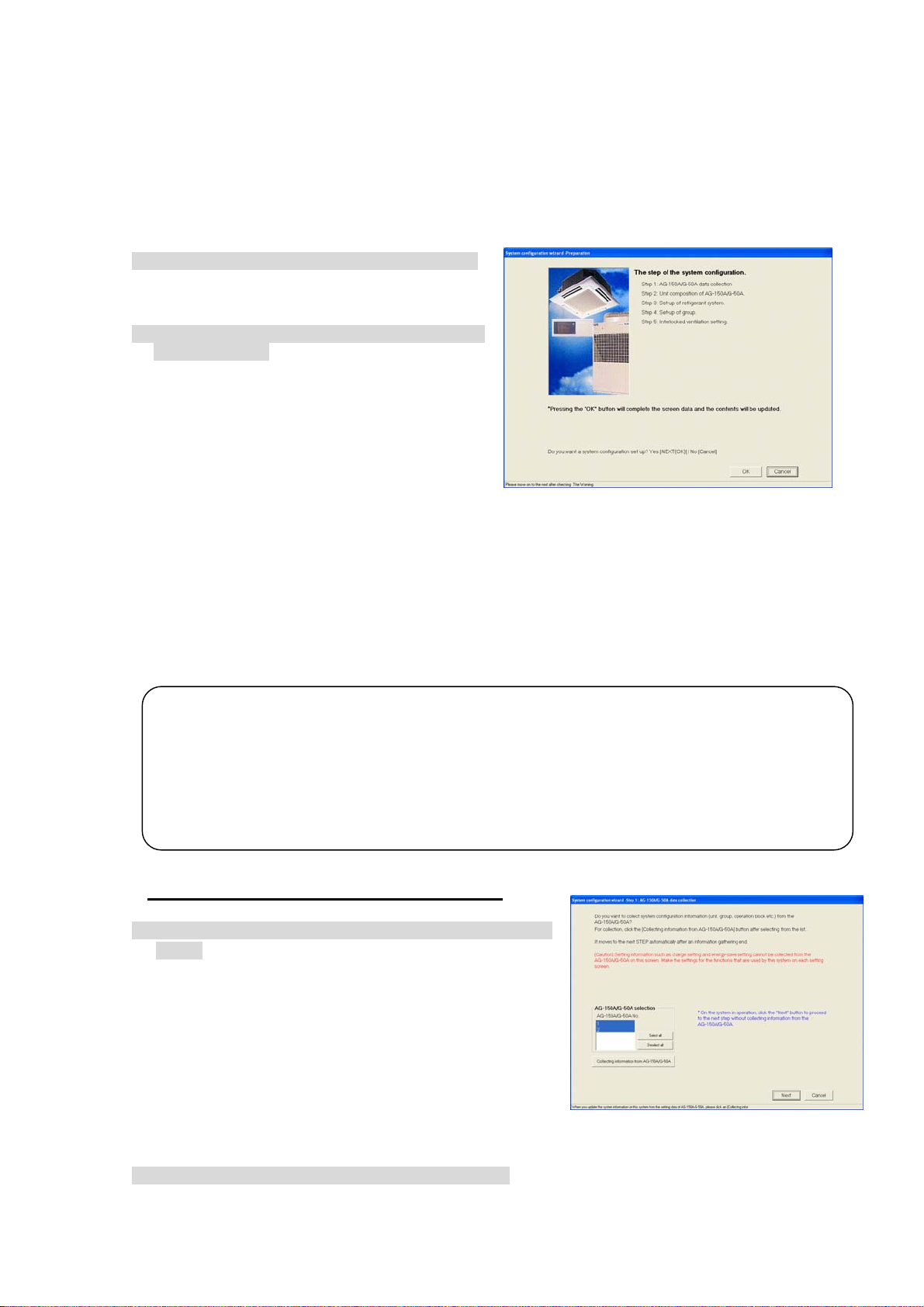
8.7 System Configuration Set-up
r
Set the information of the air-conditioning system to be monitored using this integrated centralized
control software TG-2000A. It is possible for this setting to monitor the system information possessed
by the AG-150A/G-50A.
8.7.1 Setting Procedure and Restrictions
Confirm the precautions and procedure before setting the system configuration.
Perform the confirmation before setting the system configuration.
[Procedure]
1) Select the [System configuration set-up] button.
Click the [System configuration set-up] button
located in the system setting group on the initial
window.
2) Select the [OK] button after confirming the
display contents.
Check the contents of the alarm displayed.
When there are not any problems found, click
the [OK] button to advance to the setting.
* When the [Cancel] button is clicked, this setting
is terminated to return to the initial screen.
Execute the System configuration set-up in
accordance with the following procedure.
Step 1: AG-150A/G-50A data collection
Step 2: Unit composition of AG-150A/G-50A
Step 3: Set-up of refrigerant system
Step 4: Set-up of group
Step 5: Interlocked setting
Preparation screen
8.7.2 AG-150A/G-50A data collect io n (Ste p 1)
It is possible to collect the system information (group information, interlocking ventilation unit
setting information, etc.) set for the AG-150A/G-50A with the integrated centralized control software
TG-2000A during the initial setting.
Caution:
• Note that using the AG-150A/G-50A data collecting function may cause the system information
possessed in theTG-2000A to be cleared. The AG-150A/G-50A information is overwritten when
the information is collected, so make the initial settings again (schedule, charge, peak cut o
etc.).
• It can only collect the information when the AG-150A/G-50A units are connected.
• It is recommended to execute this function after the test operation of the air conditioner and the
AG-150A/G-50A have been completed normally.
Collect the information from the AG-150A/G-50A during the initial setting.
(* Carry this step out onl y for th e fi rs t ini tia li za ti o n.
[Procedure]
1) Select the [Collecting of information from AG-150A/G-50A]
button.
To collect the system information from the AG-150A/G-50A
during the initial setting, select AG-150A/G-50A, and click
the [Collecting of information from AG-150A/G-50A] button.
After completing the information collecting, the operation
advances automatically to the next step. Wait a moment,
as it takes time for information collecting.
* When the [Cancel] button is clicked, this setting is
terminated to return to the initial screen.
Skip the collecting information from the AG-150A/G-50A.
[Procedure]
1) Select the [Next] button.
If it is not necessary to collect the information, click the [Next] button.
)
AG-150A/G-50A Data collection screen
64
Page 71

8.7.3 Unit composition set-up (Step 2)
a
-
e
f
e A
-
)
r
A
It is possible to confirm and change the configuration of the unit in each AG-150A/G-50A.
AG-150A/G-50A
Selection :
Select the
G-150/G-50A No.
Unit configur
tion tabl
Displays the system
configu
th
concerned.
:
ration unit o
G-150A/G-50A
Confirm the unit configuration.
[Procedure]
1) Select the AG-150A/G-50A No. with the “/” buttons.
In this case, use the “
configuration.
2) Select the [OK] button after checking the unit configuration of each AG-150A/G-50A.
If it is not necessary to change the unit configuration of each AG-150A/G-50A when it is checked,
click the [OK] button. *When the [Cancel] button is clicked, this setting is terminated to return to the
initial window.
※In the case of DIDO controller(DC)
When the address setting is completed, the contact number
Check the checkbox corresponding to the contact number
to DC.
※ In the case of PI controller (MCT)
When the address setting is completed, the channel number
Check the checkbox corresponding to the channel number to
screen will appear.
to be used.
※Contact number is used as a number for general equipment connecting
selection screen will appear.
be used.
Unit configuration address setting
/
“ buttons to select the AG-150A/G-50A No. desired to confirm the unit
Selected unit icon :
Displays the icons (symbols
such as the indoor unit, outdoor
unit, remote controller, system
remote controller, etc. and thei
names.
Contact Number Selection screen
Channel Number Selection screen
65
Page 72
Change the unit configuration.
y
r
[Procedure]
1) Select the AG-150A/G-50A No. with the “/ “ buttons.
/
In this case, use the “
“ buttons to select the AG-150A/G-50A No. desired to change the unit
configuration.
2) Delete/add the unit icon.
Unit icon deletion: Click the unit icon to be deleted.
Unit icon addition: Click the unit icon to be added from the selected unit icon column to set it to
the selected state.
(The symbol of the selected unit is displayed by the pointer.)
When the address column to be added is clicked, the unit icon is displayed.
Table: Icon symbol and unit name
Icon Name Address range
IC *1 Indoor unit
1 to 50
LC LOSSNAY
FU OA processing unit
KIC “K” Control Units
AIC “A” Control Units
DC *2 DIDO Controller
MCT AI controller
MCP PI controller
OC Outdoor unit
51 to 100
BC BC controller (main)
BS BC controller (sub)
OS Subsidiary outdoor unit
RC ME remote controller (compact remote controller) /
101 to 200
LOSSNAY remote controller
SC System controller (Including GR, SR, and AN)
201 to 250
GR Group remote controller
SR System remote controller
AN On/Off controller
KA K-transmission converter (201 to 250)
TR Central controller (MJ-103) (201 to 250)
G-50 Central controller AG-150A or G-50A (0, 201 to 250)
?? Unconfirmed unit (1 to 250)
*1: Two or more addresses may be assigned to some of the large-capacity indoor units.
*2:
1 contact point for DIDO Controller is converted to 1 unit. Up to 50 units are connectable to each AG-150A/G-50A.
3) Select the [OK] button.
After fully completing the unit icon change, click the [OK] button.
Note:
• When the system information is collected from the AG-150A/G-50A, all the SR, GR, and AN
display "SC".
It is possible to change the icon to that of the system controller actually connected. When the
icon is changed, it is possible to display the unit in which the error occurred with the type easil
discriminated.
• Delete the "??" icon displayed, and set the original icon. Note that it is unable to advance to the
next step if the "??" icon exists.
• If the system differs from the actual system, restart the AG-150A/G-50A or check the ai
conditioner system.
66
Page 73

(Supplement)
r
When setting unit system configuration for A-control unit s or K-control unit s, make the following
setting.
<Setting>
• Register AIC1 and AIC2 as indoor u nits.
• Outdoor unit s cannot be registered.
• Refrigerant system cannot be set.
• Make group setting.
(Measures the power
consumption of indoor
and outdoor units)
WHM for
AOC
AIC1
A-control unit
AIC2
Note:
*The apportioned electric power calculation function cannot calculate the amount of power
consumption by each individual air conditioning unit.
To measure the electric power consumption of each individual A-control unit, install a watt-hou
meter for each unit.
<Setting>
• Register KIC1 and KIC2 as indoor units.
• Outdoor unit s cannot be registered.
• Refrigerant system cannot be set.
• Make group setting.
WHM for
KOC
K-control unit
Value of Crank case heater is set sep arately.
Input capacity to KIC on the scre en.
In this case, when KIC is in the same refrigerant system
like shown in the right figure, input it to KIC
whose address is the smallest.
(Input it only to KIC1 in the right figure.)
WHM for
KIC
KIC1
KIC2
AIC: A-control indoor units AOC: A-control outdoor units
KIC: K-control indoor units KOC: K-control outdoor units
67
Page 74

8.7.4 Set-up of refrigerant system (Step 3)
t
A
t
t
It is possible to confirm and change the information of the refrigerant system within each
AG-150A/G-50A.
AG-150/G-50A Selection:
Select the AG-150A/G-50A No.
Refrigerant
System information:
Display the refrigerant
system information for
the multibuilding.
Confirm the refrigerant system information.
[Procedure]
1) Click the “/” button to select the AG-150A/G-50A No.
Click the “
2) Select the [OK] button after confirming the refrigerant system information.
If it is not necessary to change or correct the refrigerant system information for each AG-150A/
G-50A when it is checked, click the [OK] button.
* When the [Cancel] button is clicked, this setting is terminated to return to the initial window.
Change the refrigerant system informa tio n.
[Procedure]
1) Select the AG-150A/G-50A No. with the “/” buttons.
In this case, use the “
refrigerant system information.
2) Delete/add the unit icon.
Unit icon deletion: Click the unit icon to be deleted.
Unit icon addition: Click the unit icon to be added, from the unconnected indoor unit icon and
3) Select the [OK] button.
After fully completing the refrigerant system information changes, click the [OK] button.
Note:
• It cannot change the actual refrigerant system even if the addition or deletion is executed on the
refrigerant system setting change screen.
• This refrigerant system information is used for the charge calculation function. When the charge
calculation function is used, be sure to execute the setting and confirmation. This refrigeran
system information is used for error occurrence display.
• It cannot collect all the refrigerant system information depending on the AG-150A/G-50
start-up state. In this case, execute the addition or change on this refrigerant system setting
screen.
• If the display of data collected from the AG-150A/G-50A differs from the actual system, restar
the AG-150A/G-50A or check the air conditioner system.
• Setting for A-control and K-control units on the refrigerant system setting change screen is no
required.
Unconnected indoor
Unit:
Displays the indoor unit and OA
processing unit (IC, FU) for Which
the refrigerant system connection
is not displayed.
Unconnected outdoor
Sub-unit:
Displays the OS and BC for which
the refrigerant system connection is
not displayed.
/
” button to select the AG-150A/G-50A No. for which the unit Model name is to be set.
/
” buttons to select the AG-150A/G-50A No. desired to change the
unconnected sub-unit columns to set it to the selected state.
(The symbol of the selected unit is displayed by the pointer.)
When the OC column to be added is clicked, the unit icon is displayed.
68
Page 75

The information possessed by the integrated software is compared with the AG-150A/G-50A
refrigerant information when the integrated centralized control software TG-2000A starts to display
the coincidence or error message of caution in the event of no reception when this refrigerant
system setting change screen is selected.
8.7.5 Set-up of group (Step 4)
It is possible to confirm and change the group information of the indoor unit and ventilation unit
within each AG-150A/G-50A.
AG-150/G-50A Selection:
Select the AG-150A/G-50A No.
Group information:
Displays the group configuration
of the indoor unit or ventilation
unit.
Group No.:
Displays the group No.
Confirm the group information.
[Procedure]
1) Click the “/” button to select AG-150A/G-50A No.
Select the AG-150A/G-50A No. to be assigned using the “
2) Select the [OK] button after confirming the group information.
If it is not necessary to change or correct the information of each AG-150A/G-50A when it is
checked, click the [OK] button.
* When the [Cancel] button is clicked, this setting is terminated to return to the initial window.
/
” buttons.
Number of connected
AG-150A/G-50A units:
Indicates the number of AG-150A/
G-50A units connected.
Unconnected indoor unit:
Displays the indoor unit, LOSSNAY
(IC, KIC, AIC, LC, DC) not set for
the group.
Unconnected remote
Controller:
Displays the SC, GR, SR, AN,
and RC which can be set for
the group.
Change the group informatio n.
[Procedure]
1) Click the “/” button to select AG-150A/G-50A No.
Select the AG-150A/G-50A No. to be assigned using the “
2) Delete/add the unit icon.
Unit icon deletion: Click the unit icon to be deleted.
Unit icon addition: Click the unit icon to be added, from the Unconnected indoor unit and
Unconnected remote controller columns to set it to the selected state.
(The symbol of the selected unit is displayed by the pointer.)
When the group column to be added is clicked, the unit icon is displayed.
3) Select the [OK] button.
After fully completing the group information changes, click the [OK] button.
69
/
” buttons.
Page 76
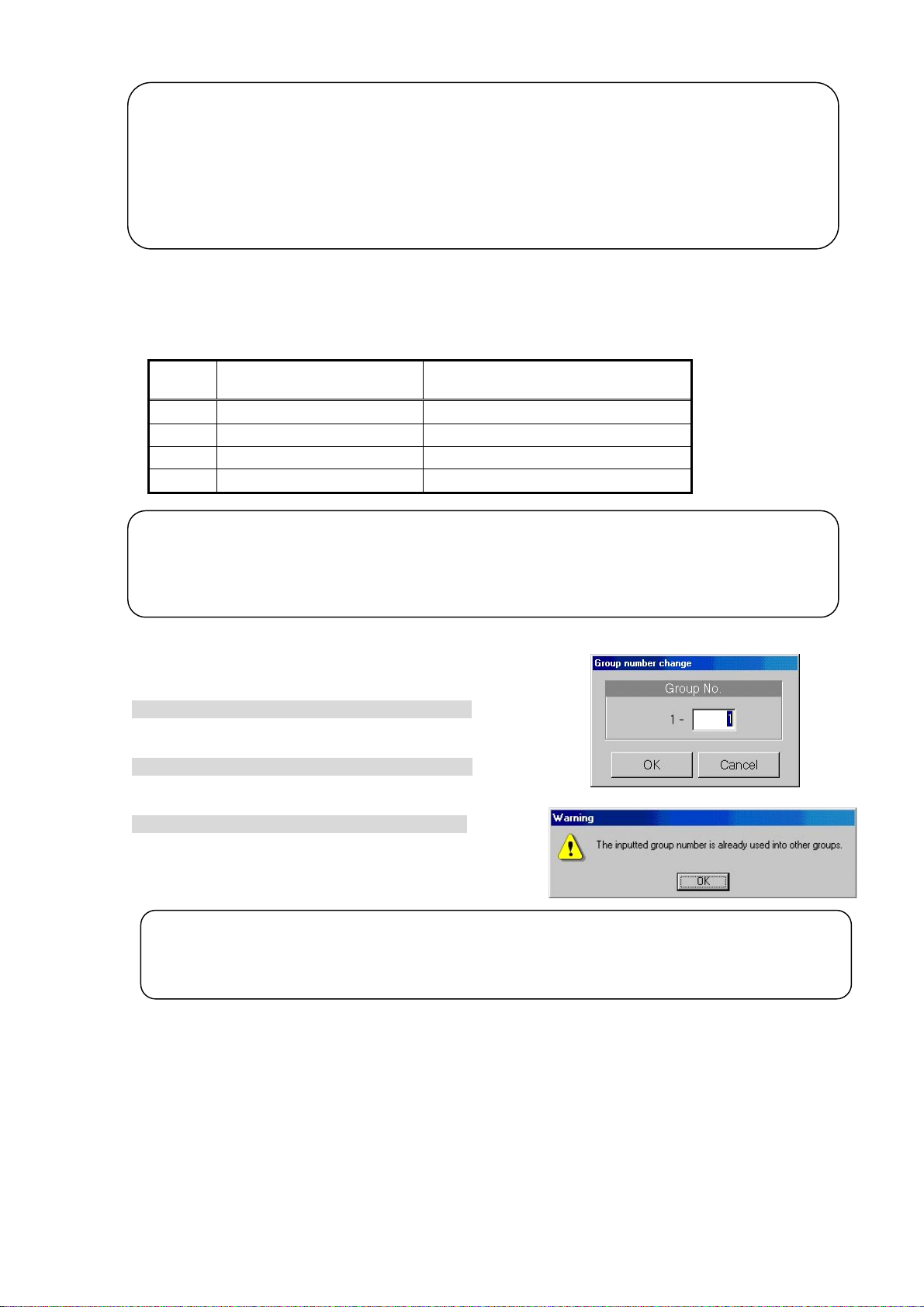
Note:
• When the group setting change screen is changed, it is possible to reflect the changed contents
on the AG-150A/G-50A system.
• It cannot set the indoor unit (M-NET type), K-control unit, A-control unit, DIDO controller and
LOSSNAY for the same group.
• Since the number of groups and the number of indoor units connectable to the GR, SR, and AN
is limited, set the group corresponding with such limitations.
• DC (DIDO controller) cannot connect with RC, GR, SR, AN and SC.
This group setting screen displays the number of groups and number of indoor units which allow
the GR, SR, AN, and SC to be newly organized.
Table: Number of management groups and number of indoor units
Symbol Equipment name
GR Group remote controller 8 groups, 16 indoor units
SR System remote controller 50 groups, 50 indoor units
AN ON/OFF remote controller 16 groups, 50 indoor units
SC System controller 50 groups, 50 indoor units
Note:
• This group setting screen displays the number of management groups and number of indoor units
for the system controller (GR, SR, AN, SC) limited when the group is newly organized.
• It is possible to use the group organization as it is, which is collected from the AG-150A/G-50A.
On/off controller (AN), etc., for instance
Change the group No.
[Procedure]
1) Select the cell of the group No. displayed.
Click the cell desired to change the group No., and the
group No. change screen is displayed.
2) Change the group No.
Use the keyboard to input the group No. to change.
* Group No. setting range: 1 to 50
3) Select the [OK] button.
Click the [OK] button after changing the group No.
If there is a duplicated group No., an error message is
displayed.
Note:
• This function is used to change groups in which a sub system controller (GR, SR, AN, SC) is
selected. The group remote controller, system remote controller and ON/OFF remote controller can
control the groups that can be set with the address 200 value.
Number of management groups and
number of indoor units
70
Page 77

8.7.6 Interlocked setting (S te p 5)
-
-
g
It is possible to confirm and change the information of ventilation unit interlocked with indoor unit
in each AG-150A/G-50A.
AG-150A/G-50A
G - 50A selection:
selection:
Select the G
Select the AG-150A/G-50A No.
50A No.
Interlocking
ventilation unit :
Displays the ventila
tion unit (LC, FU) to
interlock.
Confirm the ventilation unit interlocking set-up information.
[Procedure]
1) Select the No. of AG-150A/G-50A with “/” button.
In this case, select the No. of AG-150A/G-50A to confirm the ventilation unit interlocking set-up
information with the “
2) Select the [OK] button after confirming the ventilation unit interlocking information.
If it is not necessary to change or correct the information of each AG-150A/G-50A when it is
checked, click the [OK] button.
* When the [Cancel] button is clicked, this setting is terminated to return to the initial window.
Change the ventilation unit i nterlocking set-up information.
[Procedure]
1) Select the No. of AG-150A/G-50A with “/” button.
In this case, select the No. of AG-150A/G-50A to change the ventilation unit interlocking setting with
the “
2) Delete/add the unit icon.
Unit icon deletion: Click the unit icon to be deleted.
Unit icon addition: Click the unit icon to be added, from the Interlocking destination un-set unit
3) Select [OK] button.
Click the [OK] button after fully completing the ventilation unit interlocking setting.
Note:
• When the ventilation unit interlocking setting is changed on the interlocked setting screen, it is
possible to reflect the changed contents on the AG-150A/G-50A system.
• It is possible to set up to 16 indoor units to one interlocking ventilation unit.
• When the [OK] button is clicked, the screen to confirm whether the ventilation unit interlocking
setting is completed, is displayed.
/
” button.
/
” button.
columns to set it to the selected state.
(The symbol of the selected unit is displayed by the pointer.)
When the interlocking ventilation unit display line to be added is clicked, the
unit icon is displayed.
Interlocking destination
un - set unit :
Displays the indoor unit (IC, AIC)
to which interlockin
is not set.
71
Page 78

8.8 Set-up DIDO, AI and PI controller
Setting up each function of DIDO controller, AI controller and PI controller.
8.8.1 Setting Procedure and Restrictions
Check the setting procedure and restrictions before setting-up DIDO controller, AI controller and PI controller.
[Operation Method]
1) Click the [DIDO,AI,PI controller set-up] button.
Click the [DIDO,AI,PI controller set-up] button from system
setting group in the initial window.
2) Read the message that appears and click the [OK] button.
Read the warning message on the preparation
screen.
※
Click the [Cancel] button to cancel the procedure and
return to the initial window.
Procedure of setting-up DIDO, AI and PI controller.
Step 1 DIDO controller (General equipment) setting
Step 2 AI controller setting
Step 3 PI controller (Meter) setting
Preparation screen
8.8.2 DIDO controller(general equipment) set-up(Step 1)
Set-up function of DIDO controller (DC)
[Operation Method]
1) Select AG-150A/G-50 No. with the ▲/▼ button.
Select AG-150A/G-50A No. connected to DC with
the ▲/▼ button.
2) Set-up the detail of general equipment(DC)
Select the general equipment (DC)
Detail setting screen will appear. Please make the settings
bellow.
Group name : Short name (8 characters or less)
Full name (20 characters or less)
Allow Operation: the operate restriction of the general
equipment setting
Select an option from the following to reflect or not
reflect the on/off status change when a batch
operation is performed.
Check the radio button next to [In batch and on individual
group] to reflect the on/off status. Check the radio
button next to [On individual group] to reflect the change
on certain groups. Check the radio button next to
[No operations (Monitor only)] for the change not to be
reflected.
Monitor : the state indicate of general
equipment setting.
Either the output status to the general equipment or
input from the general equipment can be selected for
the on/off status that appears on the monitor screen.
3) Click the [OK] button.
When the setting is completed, click the [OK] button.
※Click the [Cancel] button to cancel the procedure and return to the initial
window.
DC (general equipment) Setting screen
DC (general equipment)
advanced setting screen
72
Page 79

8.8.3 AI controller Set-up(Step 2)
Set-up the function of the AI controller (MCT)
[Operation Method]
1) Select AG-150A/G-50 No. with the ▲/▼ button.
Select a AG-150A/G-50A No. connected to AI Controller
(MCT) with the ▲/▼ button.
2) Set-up the detail of measuring instrumentation.
Select the measuring instrumentation.
Detail setting screen will appear. Make the setting for the
following items.
Sensor name : Short name (8 characters or less)
Full name (20 characters or less)
Sensor type : no use (the sensor is not used)
Temperature (the temperature sensor
is used)
Humidity (the humidity sensor is used)
Measurable range: In the case of selecting temperature,
the range should be –100°C to 100°C
(-148°F to 212°F).
In the case of selecting humidity,
the range should be 0% to 100%.
* Warning appears when the range
is incorrect.
Setting for upper limit alarm:check the checkbox then enter the arbitrary value within the range.
* warning indicates when the range is incorrect
Setting for lower limit alarm:check the checkbox then input the arbitrary range within the limits.
* warning indicates when the range is incorrect
Note:
• When the setting value exceed the “upper linit alarm” or “lower limit alarm”, the AI contoller icon
will turn orange.
• AG-150A/G-50A has the function of reporting the “upper linit alarm” or “lower limit alarm” by email.
3) To correct the measurement value
If corrections need to be made for the measurement data, offset values
can be set in the screen on the right.
Click the Offset button on MCT advanced setting screen.
Measured value correction screen will appear.
Please set the Offset value or Display. (Offset value and Display are
interlocked.)
Offset value : The value can be set at 0.1 increments within the range of
-10.0~+10.0.
Display : Based on the measured value, the value can be set at 0.1
increments within the range of –10.0~+10.0.
*Measured value and display value will not appear at the initial setting
because there is no record.
4) Set-up the measuring system information.
Setting for the interval to get the trend data.
Please select the value from 1/2/5 with the ▼ button.
1)
4)
5)
MCT setting screen
2)
MCT advanced setting screen
3)
Measurement value
correction screen
73
Page 80
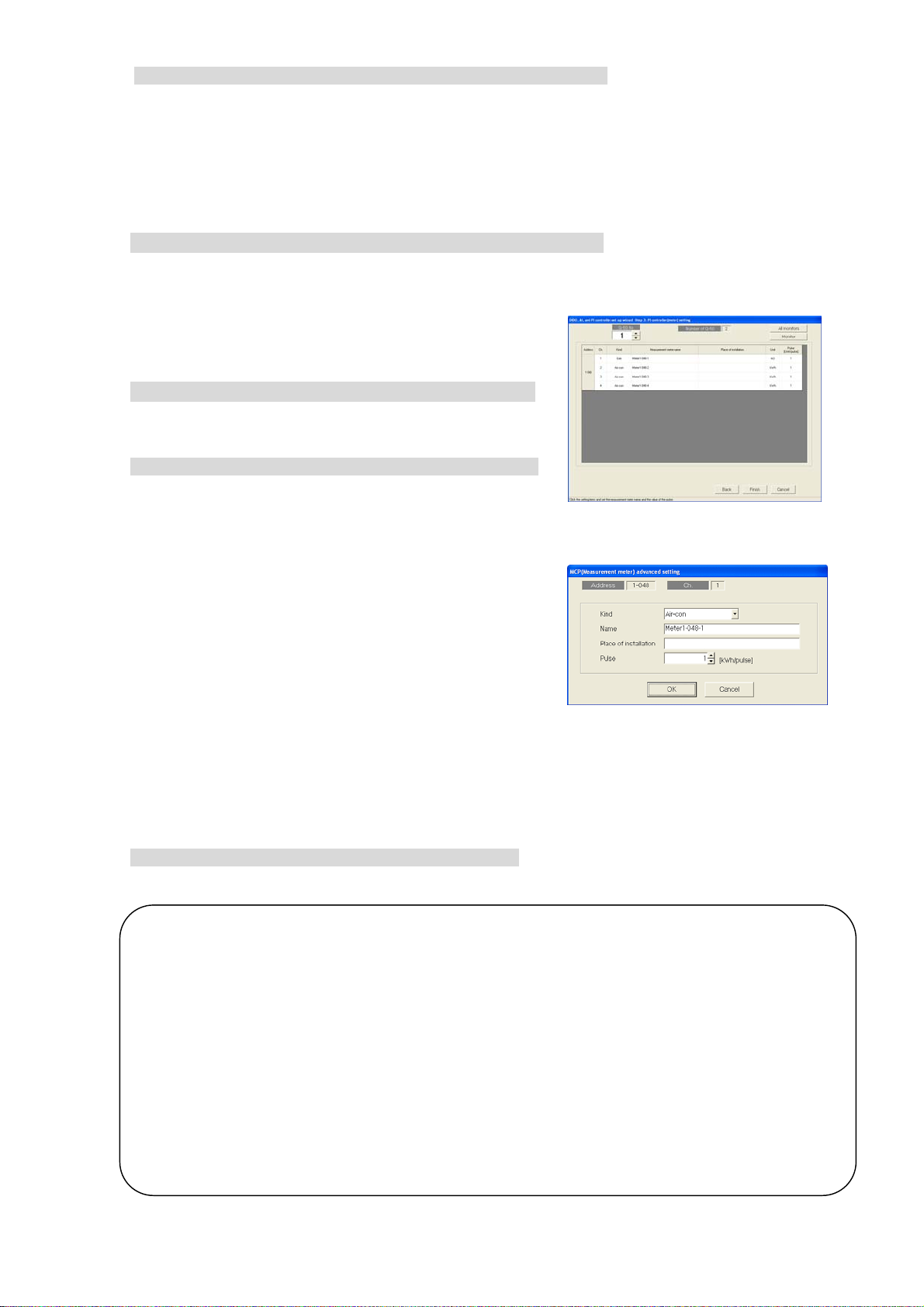
5) Set-up the CSV form of AG-150A/G-50A.
e
Setting the unit of measure and delimiter for CSV.
Decimal point : dot or comma.
CSV delimiter : comma or semi-colon.
* If comma is selected as the decimal delimiter, semicolon will automatically be selected as the CSV
delimiter (fixed).
If comma is selected as the CSV delimiter, period will automatically be selected as the decimal delimiter
(fixed).
6) Click the[OK]button.
When the setting is completed, click the[OK]button.
※Click the[Cancel]button to cancel this procedure and return to the initial window.
8.8.4 PI controller (Meter) Set-up (Step 3)
Set-up the PI controller (MCP) functio n
[Operation Method]
1) Select AG-150A/G-50A No. with the ▲/▼ button.
Select AG-150A/G-50A No. connected to PI Controller with
the ▲/▼ button.
2) Set-up the detail of measurement
Click the measurement to make a setting.
The screen of measurement will appear and make the settings
below.
Usage type: Select one from Air conditioner/Electricity1/
Electricity2/Gas/Water/Heat/Other.
Measurement name: 20 characters or less.
Placement: 20 characters or less.
Pulse: Set the value of measurement per pulse (kWh etc.)
within the rang of 0.01~100.00.
The pulse setting of the PI controller that is registered to the AG-150A/G-50A can be monitored.
Press the [All monitors] button to monitor all AG-150A/G-50A units, and press the [Monitor] button to monitor
only the selected AG-150A/G-50A unit. The acquired information will appear on the “PI controller (meter)”
screen. (The pulse setting of the PI controller that has not been registered to TG-2000A cannot be
monitored.)
3) Click the [OK] button.
When the setting is completed, click the[OK]button.
* Click the[Cancel]button to cancel the procedure and return to the initial window.
Note:
• Always set the meter pulse unit. If not set, the cumulative usage amount will not be correctly
measured and the charging function will not work properly.
• When using the Measurement Meter, give a test run for proper period to check the finite difference
of the value measured by the meter matches monitor value.
• Check that the dipswitches for the channel that is used by the PI controller are set as follows: “Us
of input contact : Yes”; “Pulse unit (weight) value setting: SC setting”.
If “Use of input contact” is set to any setting other than “Yes,” pulse input to the PI controller will be invalid and
pulse count cannot be taken.
If “Pulse unit (weight) value setting” is set to a setting other than “SC setting,” the pulse setting from
TG-2000A will be invalid, and the PI controller’s dipswitch setting will override the TG-2000A’s setting.
Refer to the PI controller Installation/Instruction Manual for how to set the dipswitches of the PI controller.
• Use a watt-hour meter with the pulse size of 1 kWh or below to measure the apportioned electric
power.
MCP setting screen
MCP advanced setting screen
74
Page 81

8.9 PLC for general equipment set-up
Set the functions for the PLC for general equipment, and information on the general equipment
connected to the PLC for general equipment monitored by this integrated software TG-2000A.
8.9.1 Setting Procedure and Restrictions
Before setting the PLC for general equipment, check the precautions.
[Procedure]
1) Click the [PLC for general equipment Set-up] button.
From the initial window, click the [PLC for general
equipment Set-up] button in the System Settings group.
2) Click the [OK] button after checking the display
contents.
Check the details displayed in the warning, and then
click the [OK] button.
* When the [Cancel] button is clicked, this setting is terminated to
return to the initial window.
The PLC for general equipment is set in the following
order.
Step 1 Number of PLC unit set-up
Preparation screen
Step 2 PLC set-up and initial setting
Step 3 Function setting
Step 4 Advanced setting (air conditioner status monitor setting)
Step 5 Advanced setting (peak cut function setting)
Step 6 General equipment set-up
8.9.2 Number of PLC unit set-up (Step 1 )
Set the number of connected PL C u ni ts.
[Procedure]
1) Select the number of connected PLC units.
Select the number of connected PLC units by
clicking “
Number of connected units: 1 to 20 units
* This value can be input from the keyboard.
2) Click the [OK] button.
After making the settings, click the [OK] button.
* When the [Cancel] button is clicked, this setting is terminated
to return to the initial window.
/
” button.
Number of unit
set-up buttons
Number of PLC unit set-up screen
75
Page 82
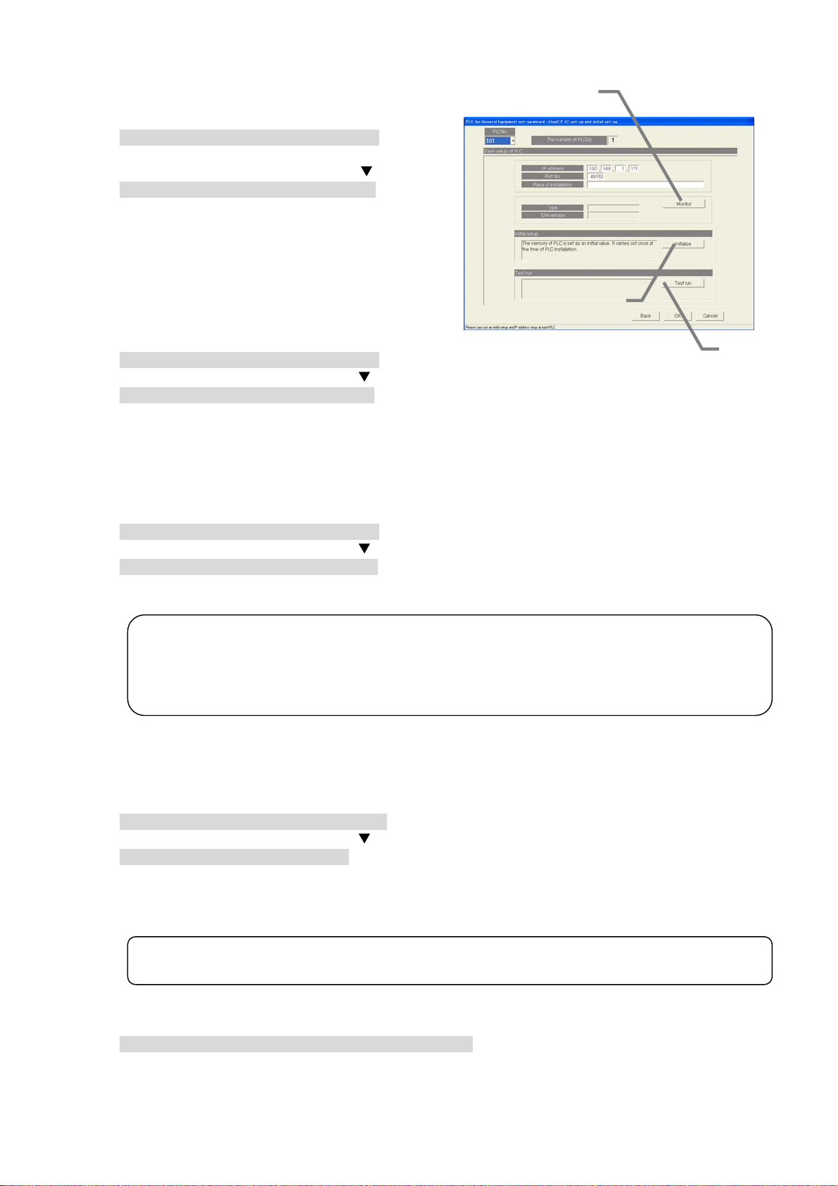
8.9.3 PLC set-up and initial setting (Step 2)
Set the PLC IP address.
[Procedure]
1) Select the PLC No.
Select the No. of the PLC for which the IP
address is to be set by clicking the “
2) Set the IP address
Register the PLC IP address in the integrated
software.
* The IP address is set in the PLC using the PLC.
* Recommended IP address: 192.168.1.171 to 190
Set the IP address for all connected PLC for
general equipments by repeating steps 1) and 2).
” button.
Monitor the PLC version
[Procedure]
1) Select the PLC No.
Select the PLC No. by clicking the “
2) Select the [Monitor] button.
Click the [Monitor] button in the PLC Connection Set-up window. The PLC software type and
version are monitored and the results appear.
* A warning message appears if the address setting or communication confirmation fails. Check the setting details.
* Proper communication can be confirmed with the PLC version monitor.
” button.
Monitor button
Initial request button
PLC connection set-up screen
Initialize the PLC
[Procedure]
1) Select the PLC No.
Select the PLC No. by clicking the “
2) Select the [Initial Setting] button.
When the [Initial Request] button on the PLC Connection Set-up screen is clicked, the PLC
memory is initialized so that it can be used.
Note:
• All settings are initialized when the PLC is initialized, and all data are erased. This "Initial
Setting" must be carried out only once when initially setting the PLC.
If this is executed during operation, the general equipment's control data will also be cleared and
the system will not operate correctly.
” button.
Setting the PLC to the trial operation mode
Use this to run the PLC for general equipment temporarily when the "PLC for general equipment"
license is not registered in the AG-150A/G-50A.
[Procedure]
1) Select the PLC No.
Select the PLC No. by clicking the “
2) Select the [Test run] button.
When the [Test run] button on the PLC Connection Set-up screen is clicked, the PLC will run in the
trial operation mode.
The operation mode display will change to " Test run Mode" while the PLC is running in the trial
operation mode. "Normal Mode" is displayed when the PLC is not in the trial operation mode.
Note:
• The PLC " Test run Mode" will automatically change to the "Normal Mode" on the next day.
” button.
Close the PLC Connection Set-u p scr een
[Procedure]
1) After making all of the settings, select the [OK] button.
* When the [Cancel] button is clicked, this setting is terminated to return to the initial window.
Test run
button
76
Page 83

8.9.4 Function setting (Step 3)
r
r
Setting the PLC function
[Procedure]
1) Set the function.
Select the function to be used with each PLC.
2) Select the [OK] after making the setting.
Note:
• The air conditioner status monitor function and
peak cut function cannot be set for the same
PLC.
Similarly, the general equipment status monito
function and peak cut function cannot be set fo
the same PLC.
• “Air-conditioner state monitoring function”
includes the monitoring function of the general
equipment connected to the indoor unit free
contact points, and the interlock control function.
* When interlocking control is performed,
“Air-conditioner state monitoring function”
must be set to “Activate”.
8.9.5 Advanced setting (air co nd it ioner status monitor setting) (Step 4)
Setting the AG-150A/G-50A for air conditioner status
monitor
[Procedure]
1) Select the PLC No.
Select the PLC No. by clicking the “
2) Select the AG-150A/G-50A No. to be monitored.
Select the No. of the AG-150A./G-50A to be monitored
by each PLC.
* If a PLC for which air conditioner status monitor is
not selected in Step 3, the message "This function
cannot be used." will appear. To use this function,
return to the previous screen and set the functions
again.
Note:
• To enable the interlock control, AG-150A/G-50A to be
monitored must be set even if a PLC is not interlocked
with an air-conditioner.
” button.
When checking the set value for PLC,
press the monitor button.
8.9.6 Advanced setting (Peak cut fun ct io n se tt ing) (Step 5)
Set the AG-150A/G-50A for peak cut operations
[Procedure]
1) Select the PLC No.
Select the PLC No. by clicking the “
2) Select the AG-150A/G-50A No. to be monitored.
Select the AG-150A/G-50A for peak cut operation with
each PLC.
* If a PLC for which peak cut is not selected in Step 3,
the message "This function cannot be used." will
appear. To use this function, return to the Step 3 and
set the functions again.
Note:
• With this screen, the equipment for which the peak
cut function is enabled by connecting a demand
controller to the PLC for general equipment is set.
Set the control details of the peak cut function with
the energy saving/peak cut settings in section 8.17.
” button.
77
Page 84

8.9.7 General equipment setting (Step 6)
PLC No.
selection
Select the PLC.
General
equipment
button
Set the general
equipment. The menu
contains Change, Copy
and Paste.
Select button
Select the presence of
general equipments.
: Selected (present)
: Not selected
(absent)
* No. 1**-033 or higher
cannot be selected.
Set the general equipment's address, functions and name
[Procedure]
1) Select the PLC No. by clicking the “
Select the PLC No. to be used by clicking the “
button.
* PLC refers to the programmable logic controller.
2) Click the box in the selection field.
: Selected
: Not selected
* Use only general equipment No. 1**-1 to 32.
3) Set the name, functions and display details.
Set the following items on the General equipment Details Set-up window.
Device name (short name, full name)
Operation setting (operation, schedule)
Operation display (display characters, monitor selection)
Error and warning status display (display characters, color selection)
General
equipment
address
Displays the general
'
Device name
setting
Sets the general
equipment's name
(short name, full
name)。
Operation setting
Sets the functions for
the general
equipment's
operation setting.
• Operation
• Schedule
Number of
connected PLCs
The number of PLC units
connected is displayed.
Number of set general
equipments
The number of set general
equipments is displayed.
Function display
The functions for the set
general equipment are
displayed.
General equipment Set-up screen
” button.
”
General equipment Set-up screen
Setting the use of
previous version icon
Set the use of the previous icon on
the administration screen.
Error and
warning status
display setting
Set the validity of the
general equipment's
error display, and the
display characters.
* Only error display
No. 1 can be used.
OK button
Click on the [OK] button
after setting the general
equipment functions.
General equipment Details Set-up screen
78
Page 85

4) After making all of the settings, select the [OK] button.
* If the [Cancel] button is clicked, the settings are canceled and the General equipment Set-up screen opens.
5) After setting all of the general equipments, select the [OK] button.
* If the [Cancel] button is clicked, the settings are canceled and the General equipment Set-up screen opens.
Note:
• Up to 20 characters can be input for the general equipment's full name.
(Short name: up to 8 characters.)
• Up to 8 characters can be input for the operation, stop and error display characters.
• Single quotations (') cannot be used in the name or display characters.
• Up to eight general equipment units (addresses 1 to 8) can be connected to one PLC.
• Only "The number of abnormalities 1" in the Abnormalities/warning state can be used for one
general equipment
• The schedule function can not be selected in TG-2000A of Ver. 4.10.
• The function of general equipment can be selected the following item.
Operation, operation display and abnormalities/warning status
Operation and operation display
Operation
Abnormalities/warning status
• The general equipment's operation setting and display functions should be set to "Operate"
and "It is updated automatically.". If "It is updated from TG-2000A only." is used, the screen
display and actual general equipment state may not match.
.
Change the general equipment settings
[Procedure]
1) Select the general equipment No.
Click the general equipment No. to be
changed. A submenu opens.
2) Select the [Change] button.
When [Change] is selected from the submenu,
the General equipment Details Set-up window
opens.
3) Set the details to be changed.
Set the details to be changed on the General equipment Details Set-up window.
4) After making all of the settings, select the [OK] button.
* If the [Cancel] button is clicked, the settings are canceled and the General equipment Set-up screen opens.
Copy the general equipment functions
[Procedure]
1) Select the general equipment No.
Click the general equipment No. to be
changed. A submenu opens.
2) Select the [Copy] button.
When [Copy] is selected from the submenu,
the details set for the general equipment are
copied.
3) Click the general equipment No., and select [Paste]
Click the general equipment No. into which the details are to be pasted, and then select [Paste].
The set details are reflected onto the General equipment Set-up screen.
* The general equipment's name is also copied, so change it on the General equipment Details Set-up screen.
79
Page 86

8.10 IC I/O Signal Set-up
t
Set the information on the general equipment connected to the IC I/O signal monitored with this
integrated software TG-2000A.
Notes
To use the free contact on the indoor unit, it must be enabled by switching the dipswitches on the
indoor unit. Make the settings by following the table below.
The indoor units of R410A compatible models or R407C compatible models ver. 33 or later (*1) have a free contact.
*The version can be checked in the indoor unit version display on the maintenance tool.
Function Switch setting Other functions
Enabled
Disabled
Free
contact
(Reference) On the models before the ones with a free contact, the following switches are used to configure the following settings:
SW1-5: Remote display switch, SW1-9: Auto recovery after power failure, SW1-10 Power start/stop.
If the free contact function on the indoor unit is enabled, other functions on the external input/output CN32, CN51, and CN52 (excep
operation status output and abnormality output on CN51) will be disabled.
SW1-10
ON ON
ON
OFF
SW1-9 SW1-5 Power start/stop
OFF
ON
OFF ON
& auto recovery
from power
failure
ON Auto recovery
from power
failure
OFF Disabled
ON Thermo ON signal
OFF
ON Thermo ON signal
OFF
OFF
Power start/stop
Auto recovery
from power
failure
Disabled
Remote display
switch
Disabled Different from the
old switch settings.
Same as the old
display
Fan output display
display
Fan output display
Thermo ON signal
display
Fan output display
switch settings.
8.10.1 Setting Procedure and Restrictions
Confirm the precautions and procedure before setting the IC I/O signal.
[Procedure]
1) Select the [IC I/O Signal Set-up] button.
Click on the [IC I/O Signal Set-up] button located in
the system setting group on the initial window.
2) Select the [OK] button after confirming the display
contents.
If any alarms appear on the preparation screen,
check whether there are any problems.
* When the [Cancel] button is clicked, this setting is terminated to
return to the initial window.
The IC I/O signal is set with the following steps.
Step 1 : General equipment set-up
Preparation screen
Notes
80
Page 87

8.10.2 General Equipment Set-up (Step 1)
A
General
equipment
button
The general
equipment can be
set. The menu
includes Change,
Copy and Paste.
Selection
button
Select whether the
general equipment
is present.
: Selected
(Present)
: Not selected
(Not present)
Jump button
When clicked on
after inputting the
general equipment
No. (1 to 2000),
the line will jump to
that No.
Set the general equipment address, function and name.
[Procedure]
1) Click on the box in the selection field.
: Selected
: Not selected
* The number of general equipment units that can
be set differs according to the number of G-50A
units. The maximum n um ber is 200 0 uni ts.
Note:
• When PLC for general equipment (Ver.2 or later) is not connected, this function cannot be used.
General Equipment
number
The general equipment
number is displayed.
General Equipment
Name setting
Set the general equipment
name (short name, full
name).
Input-and-output
setup
Set the input/output
contact to be used.
lso set the display
characters and display
color.
2) Set the name.
Set the full name and short name at the General
Equipment Name setting.
General equipment set-up screen
General equipment details setting screen
No. of set
general
equipment
units
Display the No.
of set general
equipment units.
Function
display
Display the
set general
equipment
functions.
Select button
Click to set the
contact No.
OK button
Click the [OK] button
after setting the
general equipment
functions.
81
Page 88

3) Set the input/output.
t
Set the input/output used at the Contact setting.
4) Set the contact No.
Set the contact No. used at the Contact setting.
Select the [Select] button.
The Contact Setting screen will appear. The contact
No. will appear when the + mark at the indoor unit
address is clicked. Click on the contact No. to be
used, and select the [OK] button.
5) Set the display characters and display color.
Set the display characters and colors used for the
icon at Contact Setting.
6) Select the [OK] button after completing the settings.
* When the [Cancel] button is clicked, this setting is terminated to
return to the General equipment set-up screen.
7) Select the [OK] button after completing the all general
equipment settings.
* When the [Cancel] button is clicked, this setting is terminated to
return to the initial window. The default value is set when
new.
Note:
• Up to 20 characters can be input for the general equipment name.
• Up to eight characters can be input for the start, stop and error display characters.
• Single quotations [ ' ]cannot be used for the name or display characters.
• The function of general equipment can be selected the following item.
Operation, operation display and abnormalities/warning status
Operation and operation display
Operation
Abnormalities/warning status
• If "operation output" is validated and "operation state input" is invalidated with the contac
settings, the screen display and actual general equipment state may mismatch.
• This function does not have a schedule function.
Changing the general equipm en t settin g detai l s
[Procedure]
1) Select the general equipment No.
A sub-menu will open when the general equipment
No. to be changed is clicked.
2) Select the [Change] button.
When [Change] is selected from the sub-menu, the
General equipment details setting screen will open.
3) Set the changed details.
Set the details to be changed on the General equipment
details setting screen.
4) Select the [OK] button after completing the settings.
* When the [Cancel] button is clicked, this setting is terminated to return to the General equipment set-up screen.
Copying the general equipme nt fun c tion
[Procedure]
1) Select the general equipment No.
A sub-menu will open when the general equipment
No. to be changed is clicked.
2) Select the [Copy] button.
The general equipment setting details are copied
when [Copy] is selected from the sub-menu.
3) Click on the general equipment No., and select [Paste].
Click on the general equipment No. to be pasted to, and select [Paste]. The setting details will be
reflected on the General equipment set-up screen.
* The general equipment name will be copied in the original state, so change it on the General equipment details setting
screen.
82
Page 89
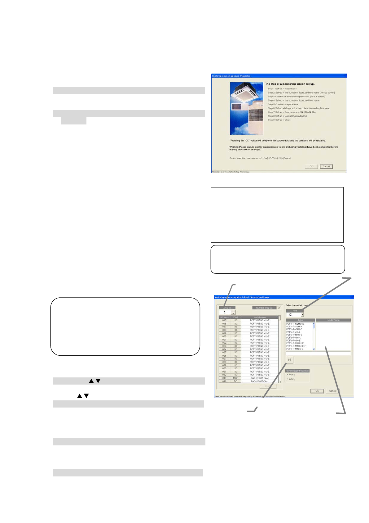
8.11 Monitoring Screen Set-up
t
Set the information such as the floor name, plan view, operation block, or other items to be monitored/
displayed on the management screen of the integrated centralized control softwareTG-2000A.
8.11.1 Configuration Procedure and Restrictions
Check these points before setting the system configuration.
[Procedure]
1) Click the [Monitoring screen set-up] button.
Click the [Monitoring screen set-up] button in the
User Settings Group in the Initial window.
2) Click the [OK] button after checking the display
contents.
Check the information displayed and click the [OK]
button.
* When the [Cancel] button is clicked, this setting is terminated
to return to the initial window.
The monitor display set-ups are done in the following
order.
Step 1 : Set-up of model name.
Step 2 : Set-up of the number of floors, and floor
name (for sub screen)
Step 3 : Creation of a sub screen plane view
(for sub screen)
Step 4 : Set-up of the number of floors, and floor
name.
Step 5 : Creation of a plane view.
Step 6 : Set-up relating a sub screen plane view
and a plane view.
Step 7 : Set-up of floor name and AG-150A/G-50A.
Step 8 : Set-up of icon arrange and name.
Step 9 : Set-up of block
8.11.2 Set-up of model name (Step 1)
Set the model name of the air conditioner unit
(outdoor unit, indoor unit, sub unit, LOSSNAY etc.)
connected to this system.
Note:
• The Charge function use this set Model name
data. When the model name is changed, the
data is monitored and control is carried ou
using that data.
• The Model name can be checked during
maintenance.
Setup the unit configuration model name
[Procedure]
1) Click the “/” button to select AG-150A/G-50A No.
Select the AG-150A/G-50A No. to be assigned using
/
the “
” buttons.
2) Select the unit to be set.
Click the units for which the same Model Name
is to be set. The selected cells are displayed in
cyan and become the objective of Model Name setup. Each time clicked, the unit is alternately
selected and removed. Multiple units can also be selected.
3) Select the Kind, Type, and Model Name.
Select the Model Name of the unit you want to set from Kind, Type, Class, and Model Name. (Kind:
IC, LC, FU, OC, BC, OS) The Model Name appears at Model Name candidate.
* Refer to Chapter 8.7.3 for details of each model.
4) Click the [Set] button.
When the [Set] button is clicked, the Model Name is reflected as a selected unit Model Name
candidate.
Monitoring screen set-up preparation screen
If the “Sub screen function setting” on User setting 1 is
“Deactivate,” the following steps will appear:
Step1: Set-up of model name
Step2: Set-u p of th e nu mb er of f loors , an d floo r name
Step3: Creation of a plane vie w
Step4: Set-u p of fl oor na me and AG-15 0A/G- 50A
Step5: Set-up o f icon ar range and name
Step6: Set-u p of block
Note:
• Some screens may not appear depending
on the validity of the functions.
Kind selection button
AG-150A/G-50A
Selection button
Set-up of model name screen
Set button
Model name candidate
83
Page 90

x
e
Note:
• The Model Name can be manually entered at Model Name candidate.
Single quotations [ ' ] cannot be used.
• The KIC and AIC type is not a database. Enter it manually.
• A remote controller or system controller Model Name cannot be set.
• When the charge function was used and the Model Name was changed, check the charge
setting set contents. The capacity value of each unit is changed.
Removing a Model Name
[Procedure]
1) Select the unit to be removed.
Click the unit whose Model Name you wish to
remove. The cell is displayed
in cyan, and becomes the Model Name setting
objective. Multiple units can be selected.
2) Click the [Delete] button.
Click the [Delete] button. The Model Name of
the selected unit is deleted.
Frequency setting
[Procedure]
1) Select the frequency.
Select the working frequency with the power
frequency selection.
50Hz: Power frequency 50Hz (default)
60Hz: Power frequency 60Hz
Delete button
Frequency check bo
Ending unit Model Name setup
[Procedure]
1) Select the [OK] button.
After fully completing the type name setting of the AG-150A/G-50A unit, click the [OK] button on the
setting screen.
*When the [Cancel] button is clicked, this setting is terminated to return to the initial window.
8.11.3 Set-up of the number of floors, and floor name (for su b scre en ) (S te p 2)
Follow these steps to set the number of floors
being managed and floor names.
Set the number of floors and floor names.
Floor
[Procedure]
1) Click the “/” button to select the number of
floors
Clicking “
/
” button selects the number of floors.
2) Click in the Floor name cell. Enter a name for each
floor.
Click the floor name cell to be set. The cell is now
ready to receive text.
Now enter the name of the floor. Do this for each
floor.
3) Click [OK] button.
When finished with these settings, click the [OK]
button.
* When the [Cancel] button is clicked, this setting is
terminated to return to the initial windows.
Note:
• The minimum number of floors is 1, the maximum is 99
• Floor names can be a maximum of 16 characters.
(Duplicate settings are possible. Single quotations ['] cannot be used.)
Set-up of the number of floors, and floor nam
Floor
name
84
Page 91

8.11.4 Creation of a sub screen plane view (Step 3)
t
e
e
r
Follow these steps to create a floor plane for each floor. This floor plane is used in air conditioning
operation and supervision for each floor. If not displaying a floor plane, it is not necessary to create
one. (The background is white.)
Note
• The floor layout that was created for the TG-2000A cannot used with the AG-150A. Likewise, the floo
layout that was created for AG-150A cannot be used with the TG-2000A.
Create a floor plane for each fl oo r
[Procedure]
1) Click the Base [Change] button.
In the Floor Plan Settings window, click the [Change]
button to edit the base plane. The paint brush appears.
A base plane serves as a basis for the whole floor screen.
To create the floor screen for each whole floor, copy the
base drawing and modify it to suit each floor.
Maintenance Tip
• When Paint Brush Mode is activated, the file
name and graphic size is set and should no
be changed. If changed, the floor plane may
not display correctly.
(*Base plane for whole floor: For 4 sections
Name: BaseFloor1000.bmp Size: W174 H100
Base plane for whole floor: For 6 sections
Name: BaseFloor2000.bmp Size: W261 H100)
2) Create a base plane.
Create a base plane with the paint brush.
* For details, see the Windows users guide.
3) Exit Paint Brush Mode.
Click the file menu and select the Exit Paint Brush
option. Select “Yes” on “the save confirmation
screen”.
4) Select a floor using the “/” button
Use the “
/
” button to select the floor to be
modified.
5) Click the Base [Copy] button.
To apply the created base drawing to the selected
floor, click the Base [Copy] button. It is not necessary
to click the Base Copy button when creating a new
floor plane.
6) Click the [Change] button
To create or edit a floor plane for the selected floor,
click the [Change] button. The paint brush starts up,
and the floor plane can be edited.
7) Create a floor plane.
Use the paint brush to edit the floor plane of the
selected floor.
8) Exit the paint brush.
Click the paint brush File menu and select the Exit Paint Brush option.
9) Click [OK] button.
After a floor plane has been created, click the [OK] button
*When the [Cancel] button is clicked, this setting is terminated to return to the initial windows.
Floor plan
Base plan
Floor selection
Creation of a plane view screen
Paint Brush window (initial state)
85
Page 92
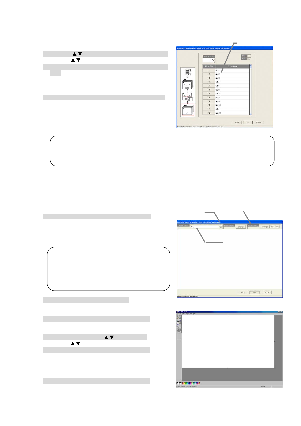
8.11.5 Set-up of the number of floors, and floor name (St ep 4)
t
y
e
e
Follow these steps to set the number of floors being managed (floor count) and floor names.
Set the number of floors and floor names.
[Procedure]
1) Click the “/” button to select the number of floors
/
Clicking “
” button selects the number of floors.
2) Click in the Floor name cell. Enter a name for each
floor.
Click the floor name cell to be set. The cell is now
ready to receive text.
Now enter the name of the floor. Do this for each floor.
3) Click [OK] button.
When finished with these settings, click the [OK] button.
* When the [Cancel] button is clicked, this setting is terminated to
return to the initial windows.
Note:
• The minimum number of floors is 1, the maximum is 99
• Floor names can be a maximum of 16 characters. (Duplicate settings are possible. Single
quotations ['] cannot be used.)
8.11.6 Creation of a plane view (Step 5)
Follow these steps to create a floor plane for each floor. This floor plane is used in air conditioning
operation and supervision for each floor. If not displaying a floor plane, it is not necessary to create
one. (The background is white.)
Create a floor plane for each fl oo r
[Procedure]
1) Click the Base [Change] button.
In the Floor Plan Settings window, click the [Change]
button to edit the base plane. The paint brush appears. A base plane serves as a basis for each floor
screen. To create the floor screen for each floor, copy the
base drawing and modify it to suit each floor.
Maintenance Tip
• When Paint Brush Mode is activated, the file
name and graphic size is set and should no
be changed. If changed, the floor plane ma
not display correctly.
(*Base plane:
Name: Floor000.bmp Size: W1000 H575)
2) Create a base plane.
Create a base plane with the paint brush.
* For details, see the Windows users guide.
3) Exit Paint Brush Mode.
Click the file menu and select the Exit Paint Brush
option. Select “Yes” on “the save confirmation screen”.
4) Select a floor using the “/” button
/
Use the “
” button to select the floor to be modified.
5) Click the Base [Copy] button.
To apply the created base drawing to the selected
floor, click the Base [Copy] button. It is not necessary
to click the Base Copy button when creating a new
floor plane.
6) Click the [Change] button
To create or edit a floor plane for the selected floor,
click the [Change] button. The paint brush starts up,
and the floor plane can be edited.
Floor name
Set-up of the number of floors, and floor
Floor plan
Base plan
Floor selection
Creation of a plane view screen
Paint Brush window (initial state)
86
Page 93

7) Create a floor plane.
g
Use the paint brush to edit the floor plane of the selected floor.
8) Exit the paint brush.
Click the paint brush File menu and select the Exit Paint Brush option.
9) Click [OK] button.
After a floor plane has been created, click the [OK] button
*When the [Cancel] button is clicked, this setting is terminated to return to the initial windows.
8.11.7 Set-up relating a sub screen plane view and a plane view (St ep 6)
Set the sections (whole floor) to be displayed on the sub-screen, and the floor related items.
Set the whole floor an d fl oo r r el ati o n i tem s
Whole floor selection
[Procedure]
1) Select a whole floor.
Use the “
/
” button to select the whole floor to be
displayed on the sub-screen.
2) Select the relation positions.
Select the position to be related from the whole
floor. The selected state will appear.
3) Select the related floor.
Select the related floor from "Selection of a floor".
4) Click the [Set] button.
The selected floor will be related to the whole floor,
and the floor name will appear.
5) When finished with all settings, click the [OK] button.
After relating the floors for the whole floor, click the [OK]
button.
* When the [Cancel] button is clicked, this setting is
terminated to return to the initial windows.
Note:
• If the relations of all floors have not been set when the [OK] button is selected, a warning
messa
e will appear. Check that the required floors have been set.
Whole floor and floor relation setting
Deleting a floor and floor relation settings
[Procedure]
1) Select a whole floor.
/
Use the “
” button to select the whole floor to be displayed on the sub-screen.
2) Select the selection to be deleted.
Select the floor to be deleted from the whole floor screen.
3) Click the [Delete] button.
When the [Delete] button is clicked, that floor will move to the floor selection.
8.11.8 Set-up of floor name and AG-150A/G-50A (Step 7)
Follow these steps to set the AG-150A/G-50A for each floor.
Set floor and AG-150A/G-50A assignments
[Procedure]
1) Select the AG-150A/G-50A.
In the Floor and G/W Options window, click the check
box of the AG-150A/G-50A to be assigned to each
floor.
: Unassigned
: Assigned
Assign a AG-150A/G-50A to every floor. (Up to 5 of
AG-150A/G-50A can be set to each floor.)
2) Click the [OK] button.
When finished with these settings, click the [OK]
button.
* When the [Cancel] button is clicked, this setting is terminated
to return to the initial window.
Set-up of floor name and AG-150A/G-50A screen
Delete button
Check box
Floor selection
Set button
87
Page 94

8.11.9 Set-up of icon arrange and name (Step 8)
y
F
t
Follow these steps to arrange group icons on each
floor plane, and enter the group name (LCD name,
short name, full name).
Set the group icons on each floor and se t their na mes.
[Procedure]
1) Select the floor using the “/” button.
In the Group Icon Layout window, use the “
button to select a floor.
2) Select a group.
With the floor showing, click the IC group or LC
group to be assigned.
3) Select the location.
Move the mouse pointer to the location where the
group is to be assigned, then click that location. When
you click this location, the group name entry screen will
appear.
* The group icons can be neatly arranged by validating the grid.
4) Enter the group name.
Enter the LCD, short and full name for the group.
* There is no LCD name for the general equipments.
5) Select the display icon.
Set the display icon for each unit.
Select the icon with either cursor button
The user icon registration setting procedure.
Users can create an original icon and import the icon with
the image file selection.
Click the user icon registration button.
User icon registration screen will appear.
Select the icon No. (1~10)
Click the icon image file selection button and select a
prepared image.
※The image size is 50x40 pixels.
After the registration is completed, click the setting
button to save the change.
6) Repeat steps 1) to 5).
Layout the groups for each floor and enter their
names.
7) Click the [OK] button after finishing with group layout.
When finished with group layout and naming, click the [OK] button.
* When the [Cancel] button is clicked, this setting is terminated to return to the initial window.
Note:
• The following limitations apply to group names.
*
LCD name is a name displayed by G-50A main part. The minus sign is used for "-" in the LCD name.
LCD name: Up to 10 characters / Short name: Up to 8 characters / Full name: Up to 20 characters
The short names are displayed on the group icons.
Depending on the characters used, the entire 8 characters may not be displayed.
Single quotations [ ' ] cannot be used.
In the long name, these characters [ ' < > & “ ] cannot be used.)
• When the [OK] button is clicked without all group icons arranged for the floor, caution is displayed. If so,
execute the group placing and naming again.
• It is possible to use the group name as it is, which is collected from the G-50A. Note that the setting can
only be executed once.
* For the unassigned group, the operation block cannot be set for the following item. Note that the charge
calculation is not executed because the setting for the charge (calculation) block cannot be executed. The
charge block cannot be set unless the operation block is set. (It is possible to execute the normal operation
for entire buildings even if the group is not assigned.)
/
”
Floor Selection
Button
Group Lis
Upper field: Air conditioner group
Lower field: General equipment
Group Icon Layout screen
Group Name Setting screen
User Icon Registration screen
Displa
ON/OF
Button
88
Page 95

t
Deleting, updating an d re nami ng gr oup s an d th ei r layout
Follow these steps to delete a group icon,
change a group name, or move a group icon.
[Procedure]
1) Click the icon.
Click on the previously set group icon.
The Delete/Change Name/Move window appears.
2) Click the “Delete”, “Change Name”, or “Move” button.
To delete the group icon, click the Delete button,
and the icon is deleted from the floor and returned to the group selection cell.
Icon layout deletion : When the [Delete] button is clicked, the group icon is deleted from the
floor display and returned to the group list.
Name and icon change: Click the [Name and icon change] button.
Name and icon change screen will appear. Change the name and the icon.
Icon movement : Click the [Move] button. Since the icon concerned is set for the selected
state, move the mouse pointer to the desired position, and click it. This
moves the icon to the desired position.
Note:
• Clicking the [Release] button located in the upper part of the screen makes is possible to release the group
icon selected.
• When the [Display OFF] button located in the upper part of the screen is clicked, the group list window is no
displayed. When the [Display ON] button is clicked, it is displayed.
89
Page 96

A
8.11.10 Set-up of block (Step 9)
It is possible to set the block for each group as an
operation block. This operation block can be also
used for the charge calculation.
Set the block groups.
[Procedure]
1) Select a floor using the “/” button
From the Block Settings window, use the “
button to select the floor.
2) Click the group icon.
Select the Group icon to be added to a block by
clicking on it. More than one group may be
selected at one time. Click on a selected group to
deselect it.
(The selected icon is displayed with red frame.)
* The state changes from selected/not selected each time the
group icon is clicked.
3) Click [Block Set] button.
With the Group icon selected, click on the [Block
Set] button. A Block Settings and Naming screen
appears.
4) Select either New or Exist.
In the Block Settings and Naming screen, use the
option buttons to select either a new block name
setting or an existing block.
5) Enter a block name or select a block name.
To enter a new block name, just enter the name. To
work with an existing block, select the block name.
6) Click [OK] button.
Click the [OK] button after setting the block name.
The label “Block**” appears in the group icon.
(**: Block No.)
* Max. 2000 blocks
7) Repeat steps 1) to 6).
Set the blocks for the groups on each floor.
8) Click [OK] button.
When finished setting blocks, click the [OK] button.
* When the [Cancel] button is clicked, this setting is
terminated to return to the initial window.
Note:
• Block names may contain a maximum of 20 characters.
(These characters [ ' < > & “ ] cannot be used.)
• If all group icons are not assigned to a block, a warning message appears. Correct this error to
proceed.
• When using the charge function, groups not assigned to blocks will not show up in the charge
information. Be sure to assign all groups to a block.
• Basically, the operation block is the same as the blocks set in the AG-150A/G-50A browser.
The operation block set with the integrated software TG-2000A can extend over AG-150A/G-50
units, but in this case, individual block settings will be used in the AG-150A/G-50A.
Name Change button
Block Set button
Release button
/
”
Set-up of block screen
Group icon select/non-select state
Block Settings and Naming screen
90
Page 97

Deleting block s et ti ng s
Follow these steps to delete block settings for a group.
[Procedure]
1) Click the group icon.
Select the group icon whose block settings you wish to delete by clicking on its icon.
2) Click [Release] button.
Select the [Release] button and the block settings for the selected group are erased. The “Block**”
label in the group icon disappears.
Note:
• If a named block has no groups assigned to it, a message appears asking if it is okay to delete the
block itself. To delete the block itself, click the [OK] button; to keep the block, click the [Cancel] button.
Changing the block name
Follow these steps to change the name of the selected
block.
[Procedure]
1) Click [Name change] button.
Click the [Name change] button in the Operation block
setting screen.
2) Select the block name.
Select the name of the block to change. The selected
block appears in the selected block cell.
3) Enter a new name.
Enter the new block name. Subsequently, enter the
other new block names ( 2) to 3) ).
4) Click [OK] button after entering the block name.
After entering the block name, click the [OK] button. The block name is monitored.
OK : Accept the new block name.
Cancel : Delete any changes and restore the earlier block name.
Block name change screen
91
Page 98

8.12 Watt Hour Meter Set-Up (For RS-485)
Set the connection to the watt hour meter.
WHM setup sets the serial ports which connect to watt hour meters and the number of watt hour meters,
address, WHM name, and maximum integrated value. It can be set for With WHM connection only.
※Refer to section 8.8.4 for the measurament meter for PI controller.
Maintenance Tip (Caution)
When changing the contents of settings related to the energy monitoring functions, be sure to compile
(date specification) the charge information up to the previous day and print it out or have the result in
hand before making changes to the settings. If charge information is not processed, the charge
information will not be apportioned correctly.
The monthly bill consists of a) + b) + standard charge
a) Charge information from the start of the current charge period to the day prior to any changes
b) Charge information from the day after any changes to the end of the current charge period
There may be a discrepancy in the charge information just before or after a change to these settings.
* For details on setting charge periods, refer to Management manual section “9.3 Air-Conditioning Charge Output”
8.12.1 Setting Procedure and Restrictions
Before setting or changing WHM, check the precautions.
Check before WHM setup.
[Procedure]
1) Click [Watt hour meter set-up] button.
From the Initial window, click on the [Watt hour meter
set-up] button in the System Settings group.
2) Click [OK] button after checking the display contents.
If there is no problem when the contents of the alarm
displayed are checked, click the [OK button.
* If the [Cancel] button is clicked, the settings are interrupted
and the screen returns to the initial window.
The Watt hour meter set-up are done in the following order.
Watt hour meter set-up preparation screen
Step 1 Watt hour meter setting
Step 2 Set-up for the name and the maximum integrated value of WHM
8.12.2 Watt Hour Meter Setting (Step 1)
Set the connection to the watt hour meter.
1) Select the port to assign to the watt hour meter.
Click the watt hour meter option button, and set the
serial port to be used.
2) Select the watt hour meter name.
Select a name to be assigned to the watt hour meter.
3) Set the number and address of the watt hour meters.
Set the number of watt hour meters to be used and
their address.
4) Set the serial No.
Input the serial No. for Model AEM31D/485 only.
Example) When S/N 70-87948, set 87948.
5) Select [OK] button.
When finished making changes, click the [OK] button.
* If the [Cancel] button is clicked, the settings are interrupted and
the screen returns to the initial window.
When address setting and communication confirmation
failed, a warning message is displayed. Check the set
contents.
Watt hour meter setting screen
Warning screen
92
Page 99
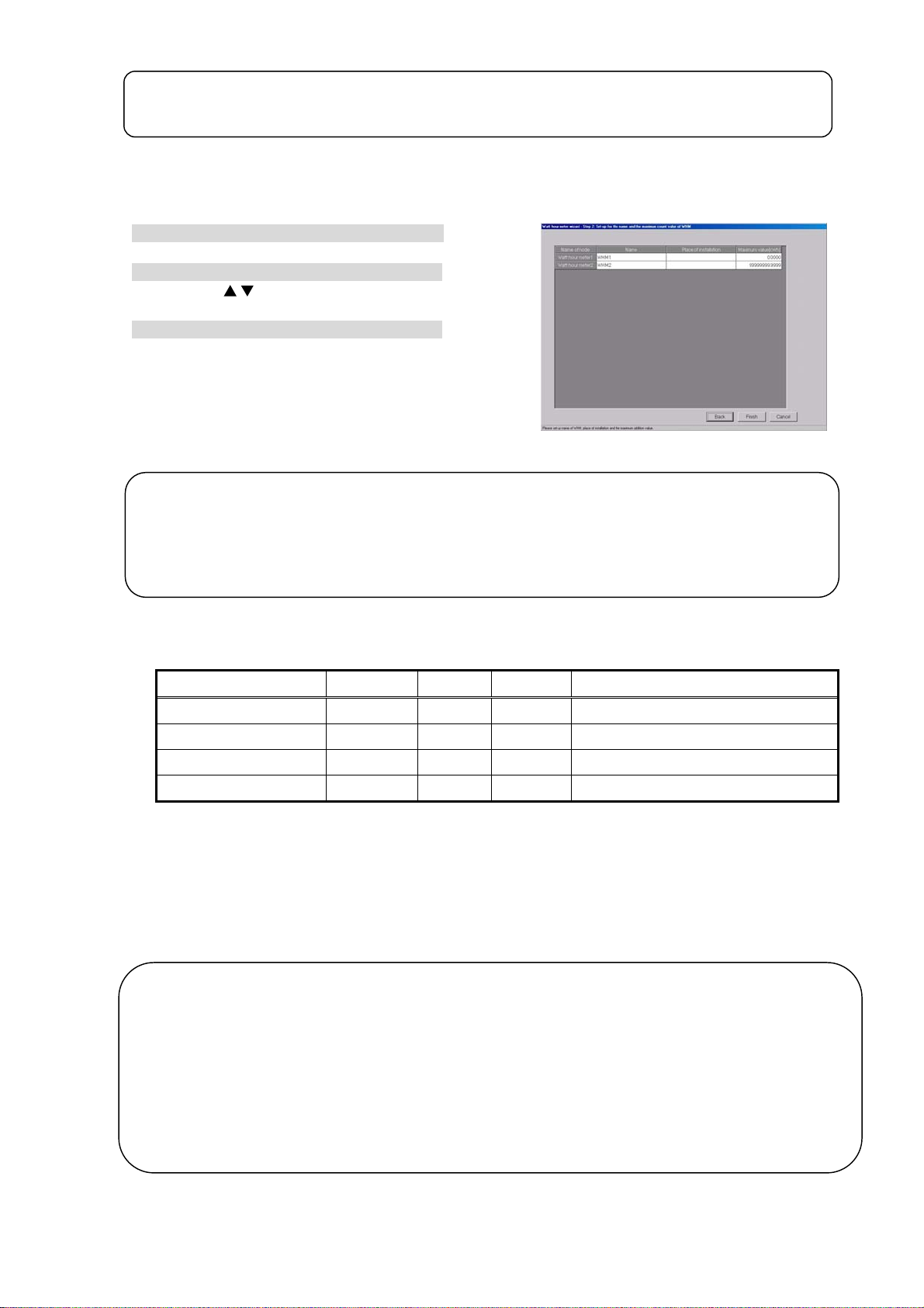
g
t
Note:
• The maximum number of watt hour meters is 30.
• If the address selected is already being used, a warning will appear. Choose a different address.
8.12.3 Set-up for the Name and the Maximum Integrated Value of WHM (Step 2)
Set the WHM name, location, and maximum integrated v alue
1) Enter the WHM name and location.
Enter the connected WHM name and location.
2) Set the maximum integrated value.
Use the “ /
WHM maximum integrated value.
” button or numeric input to set the
3) Click [Finish] button.
At the end of setting, click the [Finish] button.
* If the [Cancel] button is clicked, the settings are interrupted
and the screen returns to the initial window.
Note:
• A name and location up to 16 characters long can be entered.
• Always set the WHM maximum integrated value. If the correct maximum integrated value is no
set, the energy monitoring functions will not operate normally.
• When the WHM maximum integrated value is 0, a warning is displayed. Set the WHM maximum
integrated value.
Name and maximum inte
(Single quotation [‘] cannot be used.
rated value settings
[Reference]
Shows the communication parameters that must be set at the watt hour meter used.
Power Rail 323 9600 bps Fixed Fixed
AEM31D/485 Fixed Fixed Fixed
CVM-BC-ITF-RS485-C2 9600 bps None 1bit
ED 39din-485 9600 bps None 1bit BCD used as communications protocol.
Model Baud rate Parity Stop bit Notes
Items other than the above do not have to be set because they are fixed for each watt hour meter.
8.13 Measurement Meter Set-up (For PLC)
Set the meter connection.
The number of connected PLC for electric amount count units and IP address, and the number of
meter units, type, address, name and pulse unit, etc., are set with the meter set-up. This information
can be set only when a watt hour meter/meter is set.
Maintenance Tip (Caution)
Before changing the settings related to the charging function, settle the account to the previous day
(designated date), and record the results by printing or writing them down. The charge apportionment is
not calculated correctly if the account is not settled.
The settlement for the current month is: a) + b) + basic charges.
a) Day after settlement to previous day R Designated date settlement
b) Current day to next settlement day R Designated date settlement
There are cases when the changed day cannot be calculated correctly.
* Refer to the Management Manual "9.3 Output of Charge Air-conditioning" for details on settling the designated date.
93
Page 100

8.13.1 Setting Procedure and Restrictions
Before setting or changing the watt hour meter,
check the precautions.
Prepare the meter set-up.
[Procedure]
1) Click the [WHM Set-up] button.
From the initial window, click the [WHM Set-up]
button in the System Settings group.
2) Click the [OK] button after checking the display
contents.
Check the details displayed in the warning, and
then click the [OK] button.
* If the [Cancel] button is clicked, the settings are interrupted
and the screen returns to the initial window.
Meter Set-up Preparation screen
The watt hour meter (WHM) is set in the following order.
Step 1 Number of PLC unit set-up
Step 2 PLC set-up and initial setting
Step 3 Meter set-up
8.13.2 The number of PLC(s) (Step1)
Set the number of connected PL C u ni ts.
[Procedure]
1) Select the number of connected PLC units.
Number of unit
set-up buttons
Select the number of connected PLC units by
clicking “
* Number of connected units: 1 to 5 units
/
” button.
2) Click the [OK] button.
After making the settings, click the [OK] button.
* When the [Cancel] button is clicked, this setting is terminated
to return to the initial window.
Number of PLC unit set-up screen
Note:
• Up to 32 meters (including WHMs) can be set for one PLC.
• The meters can be set only to the models with a pulse transmitter, and are not compatible with
the level output type.
(Refer to the power rate count software installation manual.)
8.13.3 PLC set-up and initial set-up (Step 2)
Monitor button
Set the PLC IP address.
[Procedure]
1) Select the PLC No. with the
button.
Select the No. of the PLC for which the IP address
is to be set by clicking the
button.
2) Set the IP address
Register the PLC IP address in the integrated
software.
* The IP address is set in the PLC using the PLC.
* Recommended IP address: 192.168.1.151 to 155
Initial request button
Set the IP address for all connected PLC for
general equipments by repeating steps 1) and 2).
PLC connection set-up screen
94
 Loading...