

Page 1
'99 · TD-S · 001
MITSUBISHI
TRANSPORT REFRIGERATION UNIT
TDJ300D
TDJ430D
SERVICE MANUAL
Page 2

Introduction
This service manual describes the outline and maintenance procedures, etc., of the refrigeration unit, and is
intended to be used by the service personnel of the unit. Read this manual thoroughly before using to ensure
quick and waste-less servicing and to maintain the performance of the refrigeration unit.
• How to read the type
TDJ430D - 2 L 2
Indication of power voltage
[ 2: DC24V
Indication of temperature range
L: For refrigeration
[Inside temperature range: -30 to 25°C]
Indication of compressor operation
1: Vehicle driving engine operation
[
2: Vehicle driving engine operation and motor operation
Model name
[Example]
TDJ300D - 1 L 2
Type 1 (Type 2)
In this manual, these are shown by abbreviating
as type 1 and type 2.
Page 3
Safety Precautions
● Read the "Safety Precautions" thoroughly before using inspections and maintenance.
● The precautions described here are classified as " WARNINGS" and " CAUTIONS". Items that could lead to
fatalities or serious injuries during inspection and maintenance are listed as " WARNINGS". Note that even the items
listed as " CAUTIONS" could lead to series results depending on the situation. In any case, important information
related to safety is described, and must be observed.
● The meaning of the symbols used in this manual are as follows.
Never carry out. Always follow the instructions and carry out.
WARNINGS
(1) Never touch the high temperature sections such as the movable sections, exhaust pipe,
and high pressure side piping while the refrigeration unit is operating.
Failure to observe this could lead to burns.
(2)
If the refrigerant gas leaks during work, always ventilate the area.
Toxic gas could be generated if the refrigerant gas contacts fire.
(3)
According to this manual, securely install the product unit. If it is poorly installed, it will
cause refrigerant leakage, electric shock or fire.
(4)
For installation, apply the method which must be sufficiently durable for the weight of
the product unit.
If the strength is insufficient or the installation is poor, the product unit will drop
to cause an accident or wound.
(5)
Don't change any setting value of the protector or safety device. If any setting value is
changed, the product unit will be punctured or fired.
(6)
Don't mix any other refrigerant, air or similar except the specified refrigerant into the
refrigeration cycle.
If it is mixed, the pressure will become abnormally high in the refrigerant cycle, resulting in puncture
or wound.
(7)
Do not make modifications.
Making modifications could lead to injuries, electric shocks or f ires due to abnormal operation.
CAUTIONS
Before starting the refrigeration unit operation, confirm that the doors and screws for
the outer plates, etc., are completely tightened. Contacting the rotary parts could lead
to injuries.
Page 4

1. Characteristics ··········································· 1
2. Specification················································ 2
3. General information ································· 4
3.1 Controller ··············································· 4
3.2 Drive system··········································· 4
3.3 Operation control···································· 4
3.4 Defroster ················································· 4
3.5 Protective device····································· 4
4. Name of each component······················ 5
5. Adjustment of test operation················ 6
5.1 Pre-operation inspection ·························· 6
5.2 Inspection during operation····················· 6
6. Daily operation ············································ 6
6.1 Description of operation for the
controller ·················································· 6
6.2 Other operations ······································· 7
6.3 Operation of special service switches ······ 7
6.4 Operation sequence ·································· 7
6.5 Operation of display switches ·················· 8
6.6 Defrosting operation and manual
defrosting ················································· 8
7. Loading ··························································· 9
7.1 Inspection before loading ························ 9
7.2 Loading procedure ··································· 9
7.3 Unloading ················································ 10
7.4 Caution to be taken for the usage ············ 10
8. Refrigerant piping system ····················· 11
8.1
Refrigerant piping system diagram
·········· 11
8.2 Freezing cycle ········································· 11
9. Control system ············································ 12
10. Description of main parts······················· 13
10.1 Compressor ·············································· 13
10.2 Magnet clutch ·········································· 13
10.3 Heat accumulator ····································· 14
10.4 Accumulator ············································ 14
10.5 Electromagnetic valve ····························· 15
10.6 Check valve ············································· 15
10.7 Receiver ··················································· 15
10.8 Sight glass ················································ 16
10.9 Dryer ························································ 16
10.10 Condenser fan motor ······························· 16
10.11 Evaporator fan motor ······························· 17
10.12 Multi-function valve ································ 17
10.13 Expansion valve ······································· 17
10.14 Defrost thermostat (DTS) ························ 18
10.15 Dual pressure switch (DPS) ····················· 18
10.16 Storage temperature sensor (TH) ············ 18
10.17 Td sensor (Td) ········································· 19
10.18 Controller ················································· 19
10.19 Drain hose heater (option) ······················· 20
11. Electric wiring diagram ··························· 21
11.1 Sequence diagram ···································· 21
11.2 Wiring layout drawing ····························· 24
11.3 Explanation of operation ························· 28
12. Periodic inspection ··································· 34
12.1 Inspection at the time of installation
and test run ·············································· 34
12.2 Daily inspection ······································· 34
12.3 Monthly inspection ·································· 35
12.4 Six-mouth inspection ······························· 35
12.5 Bolt tightening table for each section ······ 35
12.6 Caution to be taken at the time of
daily inspection ········································ 36
12.7 Caution to be taken at the time of
periodic inspection ·································· 38
12.8 Check sheet (Installation, test run and
periodic inspection) ································· 40
12.9 Pressure table for standard operation ······ 41
13. Defect and its cause ································· 42
13.1 Diagnosis of defects on refrigerant
system······················································ 42
13.2
Charging the refrigerant <R404A>
·········· 46
13.3 Diagnosis of defects on electric parts······ 47
14. Method to select a model with
jumper cable ················································· 64
15. Refrigerant saturated pressure
table (R404A) ················································ 65
16. Installation procedure ····························· 66
16.1 Cautionary points during installation ······ 66
16.2 Cautionary and requested points
during installation ···································· 67
16.3 Reference drawing of installation ············ 71
Contents
Page 5
1. Characteristics
We have developed this refrigeration unit based on our long years of accumulation of refrigeration technique.
(1) The refrigeration unit is a compactly arranged and unitized type which can be easily installed and removed because
of a nose-mounted type.
(2) The refrigeration unit can operate in the range of the outside temperature of -5°C ~ 40°C to keep the inside
temperature in the rage of -30°C ~ 25°C. However, it is impossible to keep the inside temperature higher than the
outside temperature.
(3) The unit is easy to operate and capable of making automatic operation by switch.
(4) The refrigeration unit, which has adopted a new controller with a letter display function, can accurately establish a
desired storage air temperature digitally. And also the pre-operation inspection for the unit can be easily made by a
simple button operation, and easy diagnosis of defects will set you at ease in using the unit.
(5) The compressor is operated by the engine of a truck with a belt, and it starts and stops with magnet clutch “ON” and
“OFF”. The magnet clutch becomes “ON” and “OFF” by thermostat.
(6) The evaporator fan with DC motor installed respectively to them perform directly connected operation.
(7) Timer and manual defroster remove frost and always bring refrigeration effect into full play.
(8) New refrigerant R404A which are tender for the environments are employed.
(9) The new multi-function valve is employed. This prevents the refrigerant from returning to the high-pressure control
or compressor, and has a function for excellent start under the different pressure balance. This considerably
improves the capacity in the high temperature range, and makes the pull-down early.
– 1 –
Refrigeration unit
Controller
Compressor
Power source box
(Type 2 only)
Motor pack
(Type 2 only)
Page 6

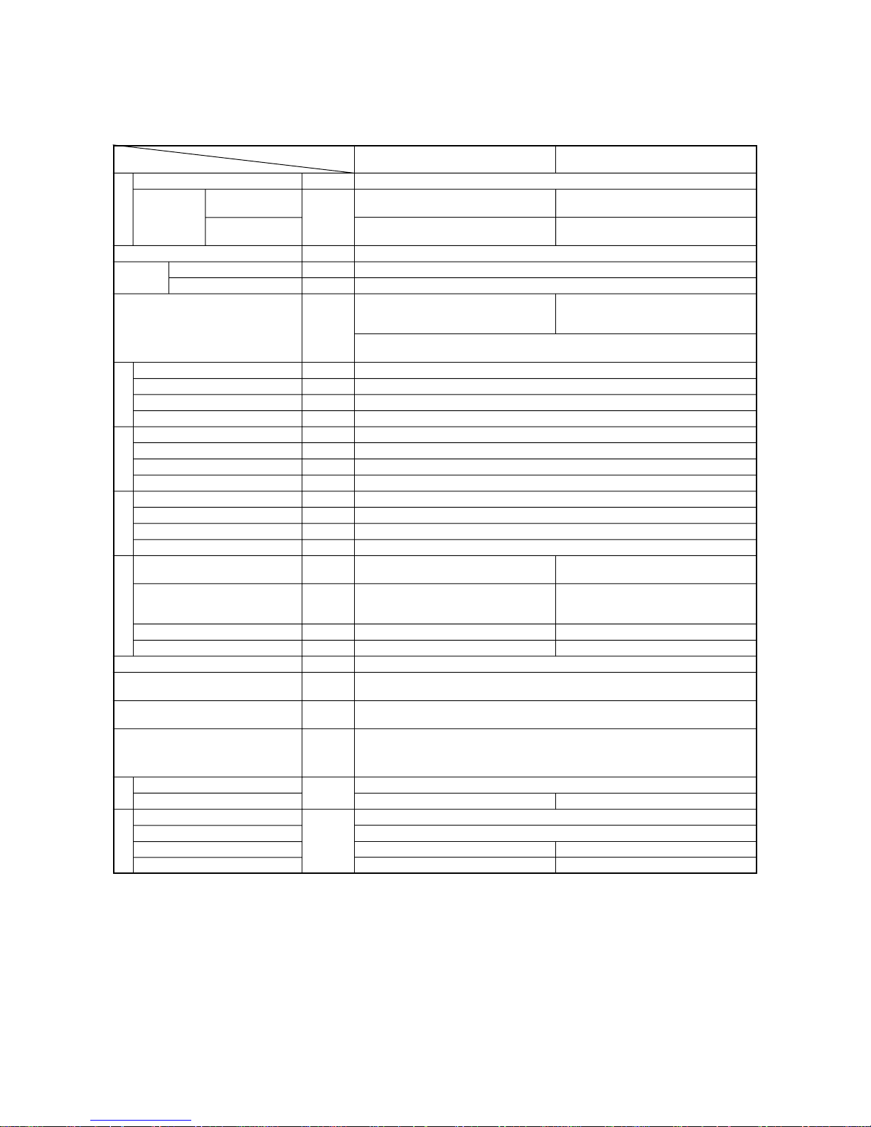
2. Specification
(1) TDJ300D
– 2 –
Ambient temperature
0°C
-18°C
Function
Inside air temperature
Outside air temperature
Drive method
Model
Discharge
Revolution
Refrigeration oil
Type
Fan
Revolution of fan
Fan motor
Type
Fan
Revolution of fan
Fan motor
Type
Power source
Revolution
Rated output
Enclosed refrigerant volume
Storage air temperature
adjustment
Defroster
Safety device
Refrigeration unit
Motor pack
Refrigeration unit
Compressor
Motor pack
Accessories
Type
Item
°C
W
(kcal/h)
°C
°C
cm
3
/rev
min
-1
cm
3
min
-1
W
min
-1
W
min
-1
kW
kg
°C
W×H×D
mm
kg
35
3490 (3000) 3490 (3000) * [2790 (2400)]
2150 (1850) 2150 (1850) * [1740 (1500)]
Cooling
-30 ~ 25
-5 ~ 40
CR2211L-A
110
600 ~ 3600 * (1420)
Diamond Freeze MA32, 350
Aluminum tube, Corrugate fin
Propeller fan, Directly connected to fan motor
2100
75 × 2
Copper pipe, Aluminum fin
Centrifugal fan, Directly connected to fan motor
2000
70 × 2
—
Totally enclosed fan-cooled 3-phase motor
3-phase AC220V 60Hz,
—
380V 50/60Hz, 415V 50Hz
—
1500/1800 (50/60Hz)
—
2.2
R404A : 1.7
-30 ~ 25 (Microcomputer controller)
Automatic defrosting (Timer system)
Dual-pressure switch
[High pressure side] CUT OUT 2.94MPa (30kgf/cm2), CUT IN 2.35MPa (24kgf/cm2)
[Low pressure side] CUT OUT 0.20MPa (2.0kgf/cm2), CUT IN 0.23MPa (2.3kgf/cm2)
Over current relay 11A (Type 2 only), Fusible plug 95°C, Discharging temperature sensor 135°C
1596 × 666 × 499
—
492 × 300 × 385
67
7.3 (Include magnet clutch)
—
54
11 45
Return air
temperature
Range of
usage
Performance
Compressor
Condenser
EvaporatorMotor
Unit size
Weight
Compressor: Belt-driven from a vehicle
engine
Condenser fan
Evaporator fan
}
Direct drive by direct current motor
Compressor: Belt-driven from a vehicle
engine and belt-driven by
motor
Note: (1) The capacity of refrigeration (performance) shown in the above parenthesis represents case of 60Hz motor drive.
TDJ300D - 1L2 TDJ300D - 2L2
Page 7
(2) TDJ430D
– 3 –
Ambient temperature
0°C
-18°C
Function
Inside air temperature
Outside air temperature
Drive method
Model
Discharge
Revolution
Refrigeration oil
Type
Fan
Revolution of fan
Fan motor
Type
Fan
Revolution of fan
Fan motor
Type
Power source
Revolution
Rated output
Enclosed refrigerant volume
Storage air temperature
adjustment
Defroster
Safety device
Refrigeration unit
Motor pack
Refrigeration unit
Compressor
Motor pack
Accessories
Type
Item
°C
W
(kcal/h)
°C
°C
cm
3
/rev
min
-1
cm
3
min
-1
W
min
-1
W
min
-1
kW
kg
°C
W×H×D
mm
kg
35
5000 (4300) 5000 (4300) * [4070 (3500)]
2790 (2400) 2790 (2400) * [2210 (1900)]
Cooling
-30 ~ 25
-5 ~ 40
CR2318LWR
181.2
600 ~ 3600 * (1420)
Diamond Freeze MA32, 800
Aluminum tube, Corrugate fin
Propeller fan, Directly connected to fan motor
2100
75 × 2
Copper pipe, Aluminum fin
Centrifugal fan, Directly connected to fan motor
2000
70 × 3
—
Totally enclosed fan-cooled 3-phase motor
3-phase AC220V 60Hz,
—
380V 50/60Hz, 415V 50Hz
—
1500/1800 (50/60Hz)
—
3.7
R404A : 2.1
-30 ~ 25 (Microcomputer controller)
Automatic defrosting (Timer system)
Dual-pressure switch
[High pressure side] CUT OUT 2.94MPa (30kgf/cm2), CUT IN 2.35MPa (24kgf/cm2)
[Low pressure side] CUT OUT 0.20MPa (2.0kgf/cm2), CUT IN 0.23MPa (2.3kgf/cm2)
Over current relay 15A (Type 2 only), Fusible plug 95°C, Discharging temperature sensor 135°C
1596 × 666 × 499
—
570 × 340 × 398
72
7.3 (Include magnet clutch)
—
85
11 47
Return air
temperature
Range of
usage
Performance
Compressor
Condenser
EvaporatorMotor
Unit size
Weight
Compressor: Belt-driven from a vehicle
engine
Condenser fan
Evaporator fan
}
Direct drive by direct current motor
Compressor: Belt-driven from a vehicle
engine and belt-driven by
motor
Note: (1) The capacity of refrigeration (performance) shown in the above parenthesis represents case of 60Hz motor drive.
TDJ430D - 1L2 TDJ430D - 2L2
Page 8

3. General information
3.1 Controller
The refrigeration unit employs a new microcomputerized
controller which has a character display function, and
the desired inside temperature can be accurately and
digitally set with the soft touch type switch. Moreover,
a trouble can be easily diagnosed.
3.2 Drive system
(1) In case of engine drive from a running vehicle
The refrigeration unit is operated in which the
engine of a running vehicle drives the compressor
by belt and condenser fan and evaporator fan are
driven by a direct current motor respectively.
After having the ignition switch of its vehicle
turned on and the vehicle started, the refrigeration
unit can be operated with the controller operation
switch "ON".
(2) In case or motor drive (Type 2)
The refrigeration unit is equipped with a motor
drive besides engine drive from a running vehicle
and can be operated by the power supply (standard
specification, 3-phase AC 220V 60Hz, 380V
50/60Hz, 415V 50Hz) at a garage, truck terminal,
ferry boat, etc.
It can be operated with the controller operation
switch "ON" after connecting three-phase power
source to an outlet of the power source box.
3.3 Operation control
When a storage air temperature is higher than the
temperature established by the thermostat, it starts
cooling operation with the magnet clutch of the
compressor connected, and when the storage air
temperature has been lowered to the temperature
established by the thermostat, the magnet clutch will be
disconnected and the fan stops together with the
compressor, which in turn stops cooling operation. The
evaporator does not stop but continues to operate.
3.4 Defroster
In order to prevent the evaporator from being covered
with frost and reducing its cooling effect, the defrost
timer (it will be established within three hours before
being shipped out from our factory) operates
defrosting.
When defrosting has been completed and temperature
of the evaporator has risen, changes to cooling
operation by the defrost thermostat. Also the evaporator
fan stops during the defrosting operation, keeping
warm air from going into the inside.
Further when the storage is loaded with watery goods
or cooling in the storage is slow, defrosting can be
made by manual operation.
3.5 Protective device
The refrigeration unit is protected both by a protective
device (dual pressure switch) which stops the unit when
discharging pressure of the compressor becomes
unusually high and the dissolving plug which
discharges refrigerant when the pressure becomes
higher due to fire, etc.
Also these devices will stop the refrigeration units
when discharging temperature of the compressor
becomes unusually high due to leakage of refrigerant,
etc. When the unit has been abnormally stopped by the
protective device (except fusible plug), an abnormal
indication lamp will display its abnormality.
– 4 –
Page 9
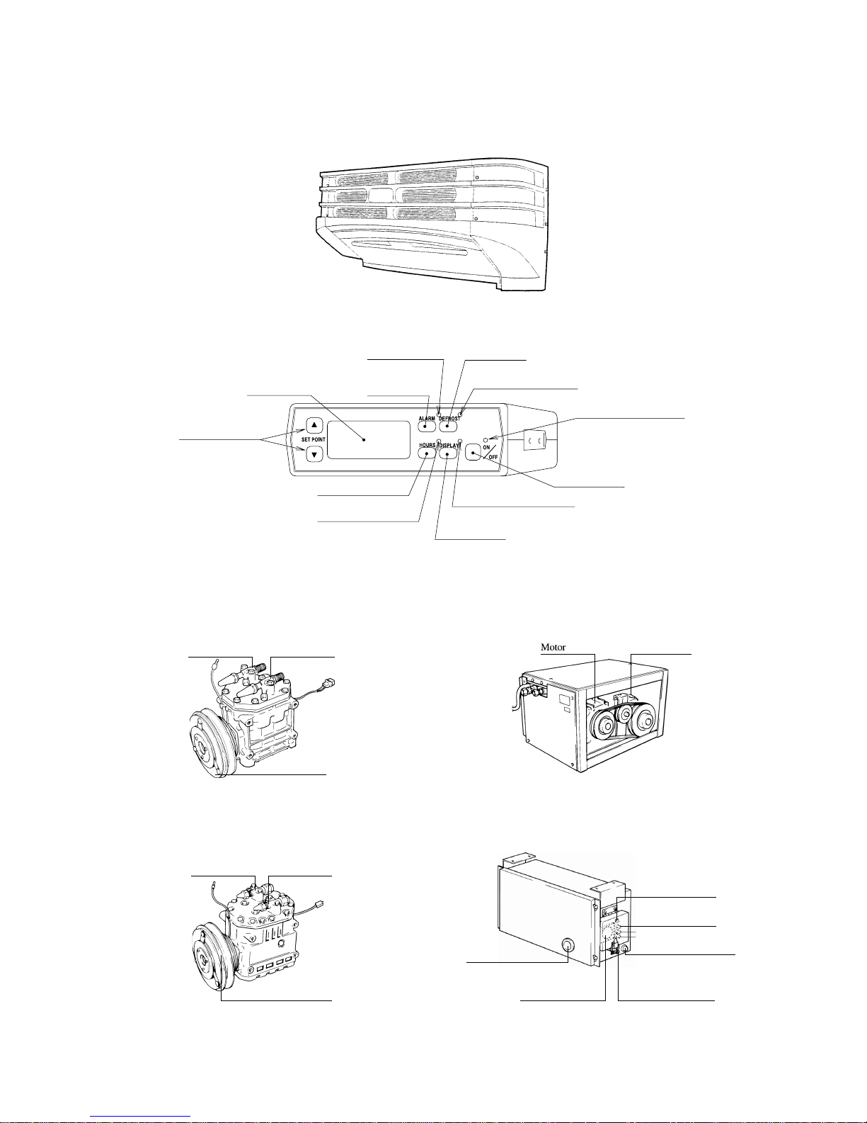
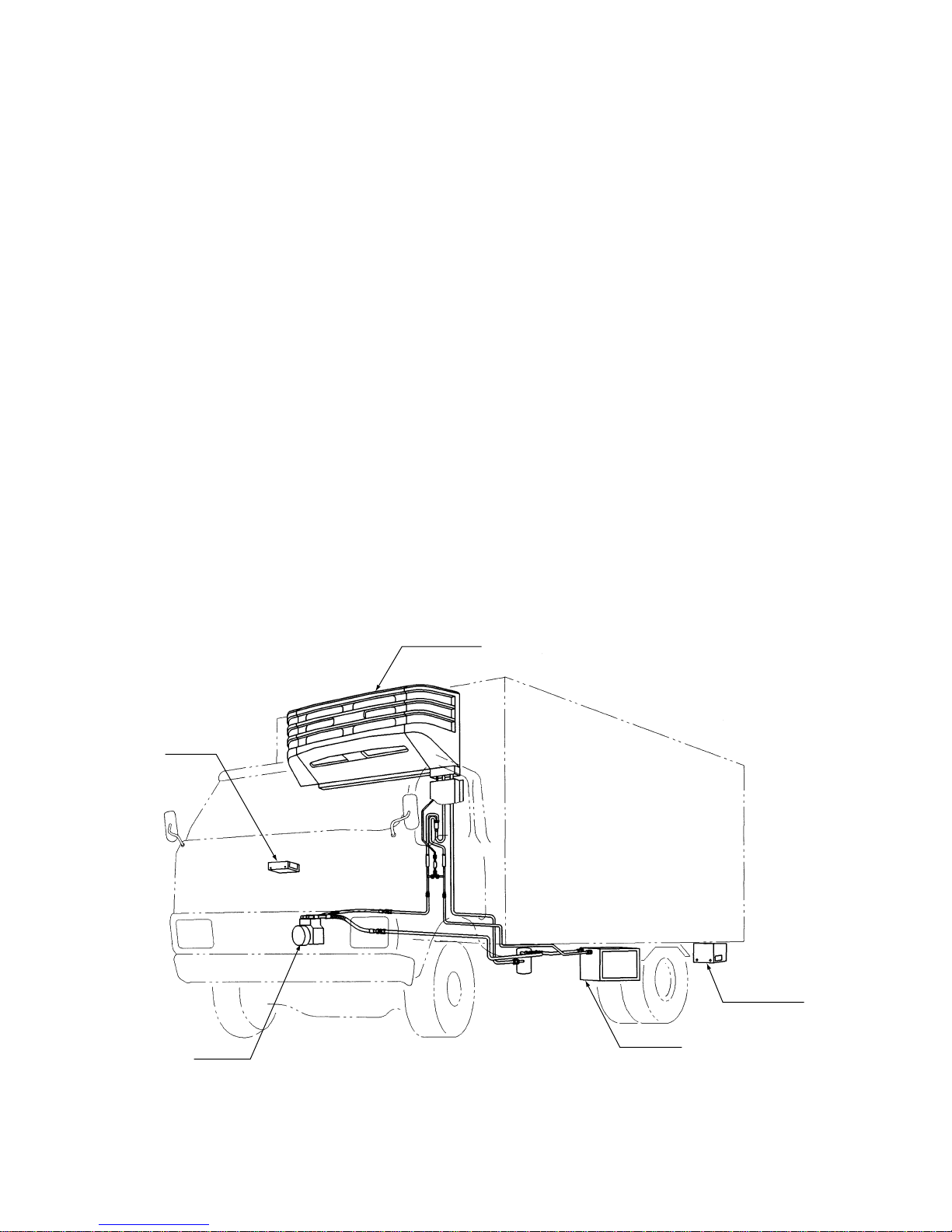
4. Name of each component
(1) Refrigeration unit
(2) Controller
(3) Compressor
(a) TDJ300D
(b) TDJ430D
(4) Motor pack (only for type 2)
(5) Power source box (only for type 2)
– 5 –
Discharge
service valve
Suction
service valve
Magnet clutch
Discharge
service valve
Magnet clutch
Suction
service valve
Limit switch
Power source outlet
Power source
indication lamp
Alarm indication lamp
(Motor overcurrent relay
active indicator)
Fuses
Manual reset button
(For motor overcurrent relay)
Compresso
r
Alarm lamp
(red)
Defrost switch
Defrost indication lamp
(orange)
Operation indication lamp
(green)
Display indication lamp
(green)
Operation switch
Display switch
Alarm switch
Digital display
Hours switch
Hours indication lamp
(green)
Temperature setting
switches
Page 10
5. Adjustment of test operation
5.1 Pre-operation inspection
(1) Check the seal going through the board of
refrigeration unit.
(2) Check if the clamp of the tubing is adequate.
(3) Check if the drain hose is connected properly and
the clamp is proper.
(4) Check the belt for looseness, degree of parallel
(Coming out of the interline) and flaw.
(5) Check if components such as compressor, pully,
belt, tubing and wiring are touching each other.
(6) More tightening of fixing bolts for the following
units.
•
Refrigeration unit
•
Compressor and bracket
•
Magnet clutch
•
Tension pulley and bracket
•
Fan motor and fan
(7) Check the electric wiring for mis-wiring and the
clamp for properness.
(8) Check the wiring terminal for looseness and the
covering of wiring for flaw.
(9) Check the refrigerant system for gas leakage (oil
leakage).
(10) Check electric wiring for grounding and defective
insulation. (Type 2 only)
5.2 Inspection during operation
(1) Check the compressor, magnet clutch, motor, fan
and tubing for abnormal sound and vibration.
(2) Check the refrigerant sight glass for color and
degree of flashing.
(3) Check the compressor and magnet clutch for start
and stop due to the thermostat.
(4) Check refrigeration (indication by temperature
display and high and low pressure).
(5) Check the defroster for operation.
(6) Check the dual pressure switch for operation.
(7) Check the motor for drive (Type 2 only) and
buzzer with ignition switch "ON".
6. Daily operation
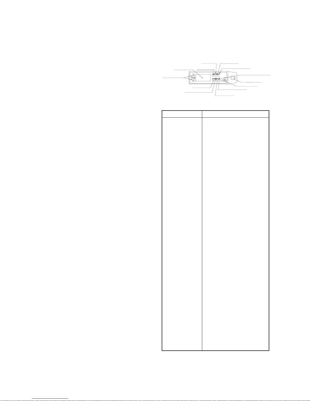
6.1 Description of operation for the controller
Description of operation for the controller
Name Operation
The switch starts or stops the
refrigeration unit.
The lamp (green) is lit when the
operation switch is on.
The switch turns on the forcible
defrosting operation.
The lamp (orange) is lit when
defrosting is in operation.
When the alarm lamp lights or blinks,
press the switch, and all faults which
occur will be indicated as the code on
the digital display unit.
When a fault occurs, the alarm lamp
(red) lights and blinks.
The in-container temperature,
incontainer preset temperature, fault
display code and integrated operation
time are displayed according to the
switches.
The switch changes the incontainer
preset temperature.
The switch makes the working time
(operation hours) of the evaporator
fan displayed.
Press the hours switch, and the lamp
(green) will come on.
When the refrigeration unit stops,
press this switch, and the incontainer
temperature will be displayed on the
digital display unit for 5 seconds.
Moreover, when the refrigeration unit
runs, press this switch, and the
incontainer temperature will be
displayed if the preset temperature,
fault code or integrated operation
time is displayed in the display unit.
Press the display switch, and the
lamp (green) will come on.
Buzzer prevents improper start.
Keeping the power code for motor
drive connected, turn the vehicle
ignition key to "ON", and the buzzer
integrated in the controller will sound
to stop the refrigeration unit.(Even if
the refrigeration unit stops, the buzzer
will sound.
– 6 –
3 Alarm lamp
(red)
2 Defrost switch
2 Defrost indication lamp
(orange)
1 Operation indication lamp
(green)
7 Display indication lamp
(green)
1 Operation switch
C Buzzer (built-in)
7 Display switch
3 Alarm switch
4 Digital display
6 Hours switch
6 Hours indication lamp
(green)
5 Temperature setting
switches
1 Operation switch
(ON/OFF)
2 Operation
indication lamp
3 Defrosting switch
4 Defrosting
indication lamp
5 Alarm switch
6 Alarm lamp
7 Digital display
8 Temperature
setting switches
9 Hours switch
0 Hours indication
lamp
A Display switch
B Display
indication lamp
C Buzzer
(Type 2 only)
Page 11

6.2 Other operations
When the refrigeration unit stops (power is supplied),
the following operations are ready.
(1) Change of inside-container preset temperature
DISPLAY ··· To higher temperature
e
··· To lower temperature
After pressing "display switch", press the switch
or , and the inside-container preset
temperature will be displayed on the digital
display unit in the blinking mode to select the
inside-container temperature setting mode.
Continuously press the switch, and the preset
temperature will vary.
··· T o higher
temperature
··· T o lo wer
temperature
(Continuously press the switch or , and the
temperature will continue varying.)
5 seconds after the finger is released from the
switch, the inside-container temperature will be
displayed.
Then, the digital display unit will go out after
other 5 seconds. Thus, it will be completely set.
(2) Integrated operation time
DISPLAY e HOURS
After pressing "display switch", press "hours
switch", and the integrated operation time will be
displayed on the digital display unit.
5 seconds after the finger is released, the inside
container temperature will be displayed. Then, the
digital display unit will go out after other 5
seconds.
Thus, it will be completed.
6.3 Operation of special service switches
When the operation switch is "off", the following
operation is ready.
(1) How to clear the evaporator operation time
1 Press the display switch.
2 Press the hours switch and temperature setting
switch together for 4 seconds, and it will be
cleared.
(2) How to display the fault history
1 Press the display switch and alarm switch together
for 4 seconds, and max. 5 faults which have
occurred will be displayed with the codes in
sequence from the newest one.
2 When the fault history is displayed, press the
alarm switch and temperature setting switch
together for other 4 seconds, and the fault history
will be cleared.
(3) How to change the defrost timer setting
1 Press the display switch and defrost switch
together for 4 seconds, and the preset temperature
will be displayed.
2 Press the defrosting switch together with the
temperature setting switch or , and the
defrosting time will be changed in the range of 1
to 6 hours.
6.4 Operation sequence
(1) In case of engine drive from a running vehicle
1 Start the engine which drives the car.
2 Turn the operation switch to "ON".
(When the operation switch comes "ON", the
operation lamp (green) will come on.)
3 Setting of inside-container temperature
Press either temperature setting switch or ,
and the inside-container setting temperature on the
digital display unit will blink to indicate the
inside-container temperature setting mode.
Keep the switch pressed as it is, and the setting
temperature will vary.
··· T o higher
temperature
··· T o lo wer
temperature
(Continuously press the switch or , and the
temperature will continue varying.)
Keep the temperature setting switch pressed, and
release the finger from the switch when the
temperature indicated on the digital display unit
reaches the inside container pressure temperature
(transportation temperature).
After 5 seconds, the digital display unit will return
to display the inside-container temperature. Thus,
the inside-container temperature setting mode will
be completed.
▼▲
Every push of the switch
changes the temperature
by 1°C.
▼
▲
▼▲
▼▲
▼
▼
▼▲
Every push of the switch
changes the temperature
by 1°C.
▼
▲
▼▲
▼
▲
– 7 –
Page 12

Since the controller is provided with the function
(memory function) which memorizes the
temperatures preset in the refrigeration unit up to
now, check the preset temperature by pressing
either temperature setting switch or one
time for the assurance's sake.
4 Stopping
• To turn it "OFF", press the operation switch
again and the refrigeration operation will be
stopped.
• Turn the operation switch to "OFF", and the
operation indication lamp and digital display
unit will go out.
Note: Before turning the ignition switch of the car to
"OFF", be sure to turn the operation switch of the
refrigeration unit to "OFF".
(2) Motor driven type (Type 2 alone)
1 Turn the ignition switch of the vehicle to "OFF",
and connect the receptacle of the motor drive
power supply to supply electric power.
Note: Before connecting the power supply, make sure
that the operation switch is "OFF".
2 Press the operation switch to "ON".
When the operation switch becomes "ON", the
operation indication lamp will come on. (Green)
3 Inside temperature setting
Press either setting switch or , and the inside
set temperature on the digital display unit will be
displayed in the blinking mode with the inside
temperature setting mode selected.
Keep the switch pressed as it is, and the setting
temperature will vary.
··· T o higher
temperature
··· T o lo wer
temperature
(Continuously press the switch or , and the
temperature will continue varying.)
When the temperature indicated on the digital
display unit is brought to a desired inside
temperature (transportation temperature) by
pressing the temperature setting switch, release the
finger from the switch.
After 5 seconds, the digital display will return to
the inside temperature with the temperature setting
mode ended.
Since the controller has the function to
memorize the temperature which was set during
last operation of the refrigeration unit, press
either temperature setting switch or once
to check the memorized temperature for
caution's sake.
4 Stopping
• Press the operation switch again to turn it to
"OFF", and cooling operation will be stopped.
• Turn the operation switch to "OFF", and the
operation indication lamp and digital display
will go out.
Note: 1) Before disconnecting the receptacle of the
motor drive power supply, be sure to turn the
operation switch of the refrigeration switch to
"OFF".
2) Don't start or stop the unit by using the power
supply breaker or connecting/disconnecting
the power supply plug. Otherwise, it will
cause an electric circuit trouble or electric
shock.
3) Prevent rain and water from splashing over
the receptacle area of the power box, or it will
cause an electric shock when the motor is
driven.
6.5 Operation of display switches
(1) When the refrigeration unit is operating
When the preset temperature, fault code or
integrated operation time is displayed on the
digital display unit, it can be returned to the insidecontainer temperature.
(2) When the refrigeration unit is stopped
Press the display switch, and the inside-container
temperature will be displayed on the digital
display unit. At this time, press the following
switch, and the selected content will be displayed.
• Single push of or ····Preset temperature
• ALARM······························Fault code
• HOURS·······························Operation time
• DEFROST···························Defrost interval time
6.6 Defrosting operation and manual defrosting
Defrosting operation is applied to prevent the cooling
effect from dropping since the evaporator is frosted.
▼▲
▼▲
▼▲
Every push of the switch
changes the temperature
by 1°C.
▼
▲
▼▲
▼▲
– 8 –
Page 13

The defrost timer (factory-set at every 3 hours at
shipment) will automatically work for automatic
defrosting.
When the delay timer of 1 minute runs out after
defrosting is completed, it will be automatically
switched into the cooling operation.
At this time, the evaporator fan is stopped to prevent
the warm wind from entering the room.
(1) Method to change the timer setting of defrosting.
Though the defrost timer was factory-set at every 3
hours at shipment, it is adjustable in the range of 1
to 6 hours.
1 Turn the operation switch to "OFF".
2 Press both display switch and defrost switch
together for 4 seconds, the preset time will be
displayed.
3 The preset time can be changed by pressing the
temperature setting switch or with the
defrost switch pressed.
(2) Manual defrosting method
If inside cooling becomes poor since frost sticks to
the evaporator, manual defrosting is possible.
Press the defrost switch during cooling operation.
• The defrost indication lamp (orange) is lit
during defrosting operation.
• The operation indication lamp is lit during
defrosting operation. (Green)
It will automatically return to the cooling
operation when defrosting is complete. (It can not
be manually returned to OFF.)
After 60 minutes, it will be automatically
returned to the cooling operation with the
defrost forced ending timer (integrated).
7. Loading
7.1 Inspection before loading
(1) Clean inside of the storage.
(2) Inspect the car side and the refrigeration unit.
(3) Establish a storage air temperature.
(4) Before loading, make sure to perform
cooling operation, and refrigerate the
storage up to an established temperature
in advance.
First of all, it is necessary to refrigerate a storage
in order to transport and deliver goods properly.
Under the blazing sun in midsummer, inside of a
storage may become as hot as 60°C. And so if
freight is put in it without cooling the storage in
advance, a defect due to improper transportation
temperature will happen.
• Operate the refrigeration unit under the shade.
• In case of engine drive, operate it with engine
running more than 800min
-1
.
• On Type 2, make pre-cooling operation done by
the motor drive.
(5) Check the sight glass during operation
and confirm that there is no bubbling and
that the checking color is green.
7.2 Loading procedure
(1) Load a refrigerator freight truck with the
goods which have been cooled to an
established air temperature in advance by
some other cooling device.
(Never load anything hot and warm in the truck
because it will only cause overloading operation to
the refrigeration unit.)
(2) Perform loading b y stopping the refrigeration
unit and in a short time, if possible.
▼▲
– 9 –
How to make an effective cooling
operation in advance.
Page 14
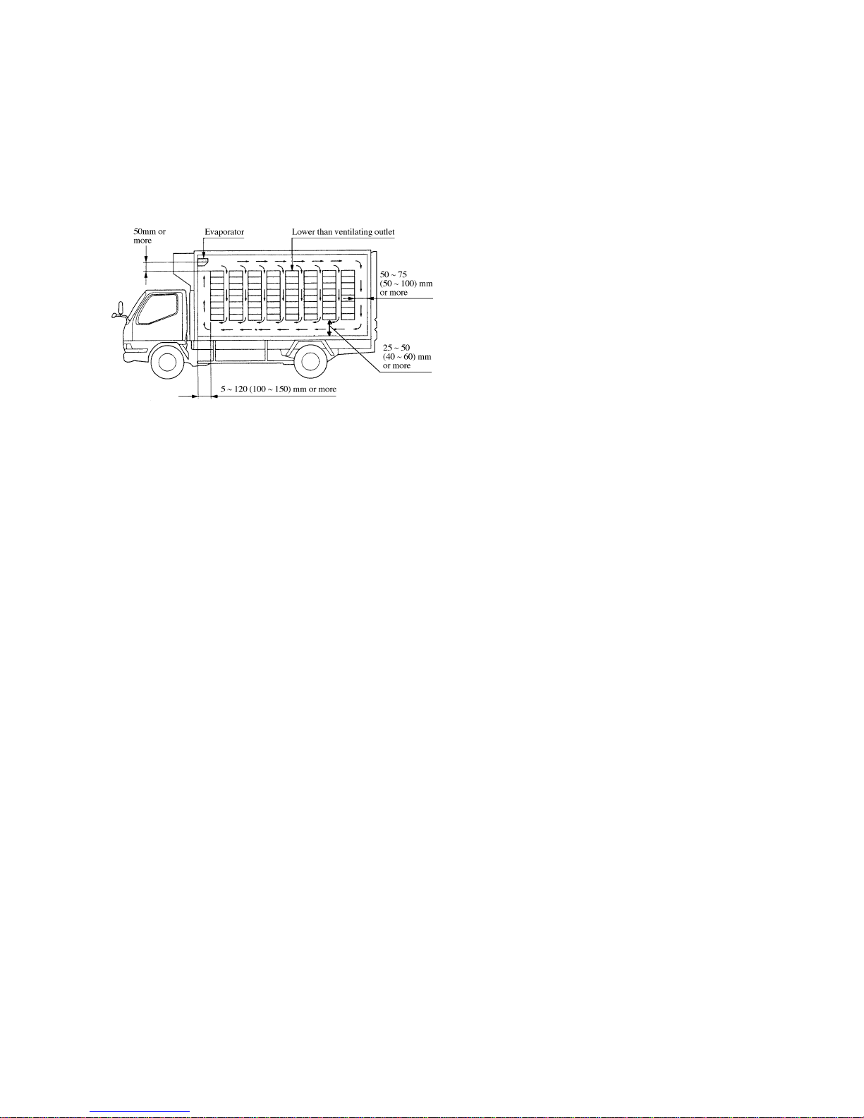
(3) Load so as to allow cool air circulating every
corner of the storage.
To circulate cold wind, the clearance between the
cargo and room wall must be 30mm or more on
both sides and the following values on the rear
side, front side and floor except the blow-out area
from the ceiling evaporator.
The values in ( ) are applicable for TDJ430D.
(4) Make the upper side of the load as flat as can be.
(5) After loading, operate the refrigeration unit.
7.3 Unloading
(1) Perform unloading after stopping the
refrigeration unit.
(2) Opening the door of the storage once will make
the inside temperature going up momentarily, so
open and close the door quickly so as to not let the
cool air out.
(3) When loading and unloading, make sure to use a
curtain in order to keep outside air from coming in
and cool air going out.
7.4 Caution to be taken for the usage
(1) In case of using a refrigerator freight truck as a
refrigerator for a long time consecutively, make
the entire indoor temperature as high as a plus
degree and melt the ice completely.
(2) Operate the refrigeration unit more than 15
minutes once in 3 or 4 days even if the unit is not
used for a long period of time.
(3) Avoid using only either the engine of a truck or the
motor of a unit for long. If one of them is not
going to be used for long, make sure to operate
either of them more than 15 minutes once in every
3 or 4 days.
Remarks: Operation procedure operate the unit for about
15 minutes, After switching "ON" and "OFF"
repeat at intervals of several seconds.
In case of driving engine operation type operate by
idling condition.
(4) The display indication of the controller may flicker
due to wireless (wireless of both our manufactured
vehicles and other makes). If a wireless in installed
in our vehicle, disconnect it.
(5) Regarding the power source and voltage of motor
drive:
• In case of standard specification, set up the
power volume which allows a rush voltage on
the refrigeration unit side to be able to secure
more than 180V when the motor is started.
• Motor specification
Standard specification 3-phases AC 220V 60Hz,
380V 50/60Hz, 415V 50Hz
• In case of using commercial power source, a
measure to cope with electric leakage for power
supply circuit is required.
(6) Washing
• When washing a vehicle, be careful not to splash
water directly to the electric equipments inside
the refrigeration unit.
• When cleaning the condenser and evaporator
coil, never make a high pressure washing by a
high pressure washing machine as it crushes the
fin. Also never make a steam washing as it
increases pressure inside of the units unusually
and is dangerous.
– 10 –
Page 15
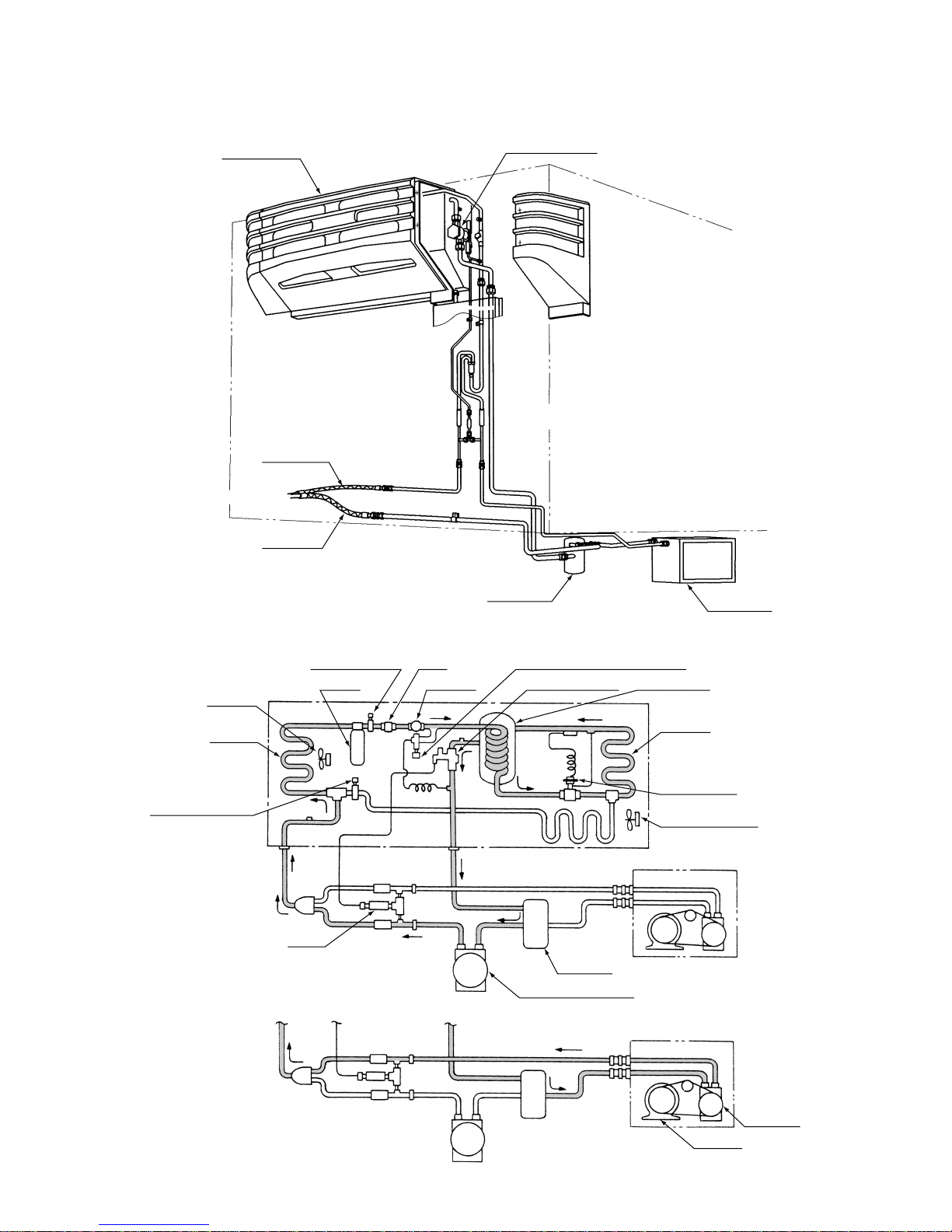
8. Refrigerant piping system
8.1 Refrigerant piping system diagram
8.2 Freezing cycle
(1) Refrigeration cycle
– 11 –
Multi-function valve
Motor pack
(Type 2 only)
Accumlator
(Type 2 only)
Refrigeration unit
Discharge hose
Suction hose
To vehicle’s compressor
Condenser
fan motor
Condenser
Dual pressure switch
Defrost electromagnetic
valve (closed)
Strainer
Motor pack
Refrigeration unit
Receiver Sight glass Multi-function valve Heat accumlator
Evaporator
Expansion valve
Evaporator fan motor
Accumlator
Compressor
AC motor
Conpressor (Engine side)
Dryer Liquid injection electromagnetic valve
(Discharge)
(Discharge)
(Suction)
(Suction)
Engine drive type
Motor drive type
Remarks:
The figure shows an example of Type 2.
Type 1 is not equipped with motor pack
and accumulator.
Page 16

(2) Defrost cycle
9. Control system
– 12 –
Defrost
electromagnetic
valve (open)
Motor pack
Refrigeration unit
Engine drive type
Motor dirve type
Refrigeration unit
Power source
box
Td2 sensor
Motor pack
To battery (+) terminal
Fusible link
On the 1 type, connect it to the battery as it is.
In case of type2
Ground
Ground
Control box
Controller
Compressor
To ignition
switch
Td1 sensor
Remarks:
The figure shows an example of Type 2.
Type 1 is not equipped with motor pack
and accumulator.
Page 17
10. Description of main parts
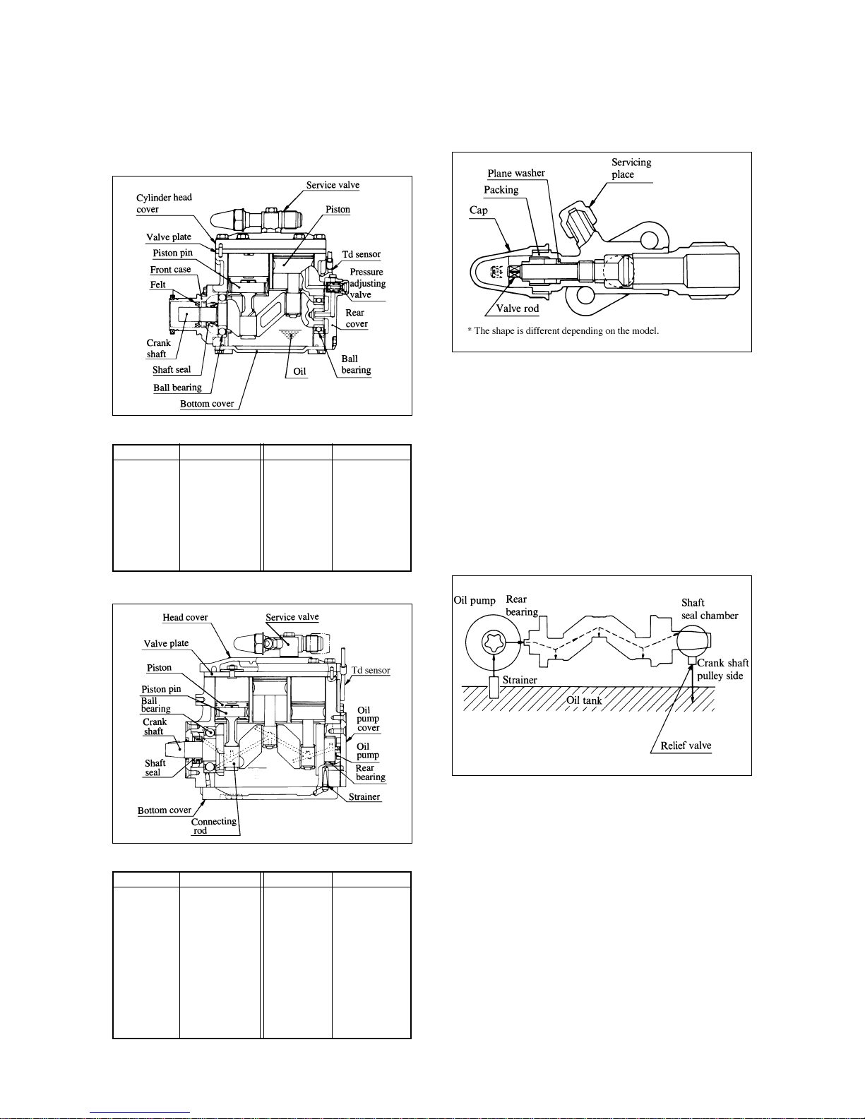
10.1 Compressor
(1) TDJ300D
(2) TDJ430D
(3) Service valve
The compressor are equipped with a suction
service valve and discharge service valve.
Note: When working the pipe for service, finally
connect the suction and discharge pipes of the
compressor since the refrigerator oil is highly
liable to absorb water.
(4) Lubrication system (TDJ430D)
Lubrication oil is supplied forcibly to respective
bearings, pistons, tank shaft pins and shaft seals by
the oil pump.
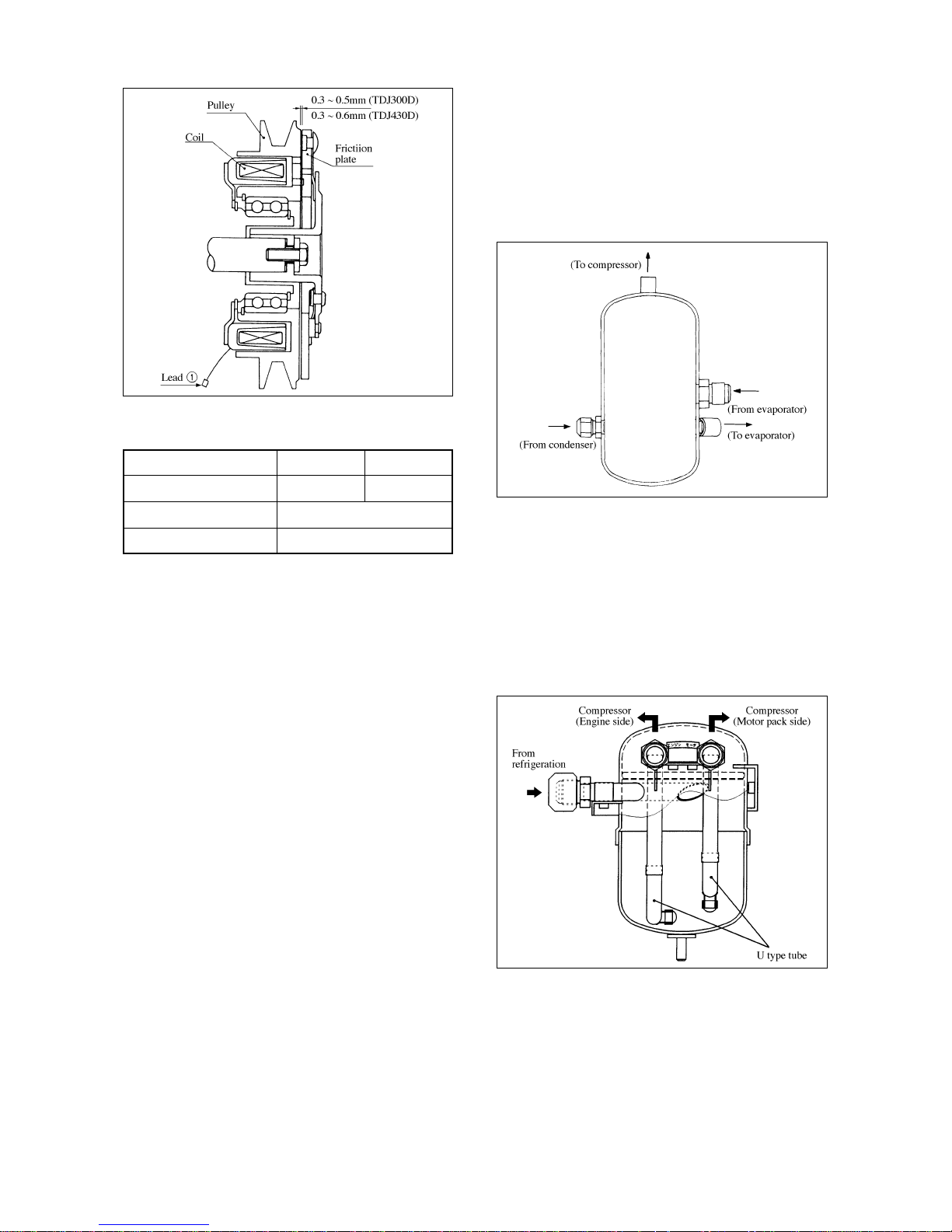
10.2 Magnet clutch
The magnet clutch is installed in the crank shaft of the
compressor, and turns on and off the compressor by
indication of the thermostat. When cooling is required
it is "ON" and when not required it is "OFF".
– 13 –
CR2211L-A
Name
Model
Volume of
discharge
Revolution
Specification
CR2211L-A
110cm
3
/rev
600 ~ 3600min
-1
(motor 1420min-1)
Name
Weight
Lubricating
oil
Amount of
oil
Specification
7.3kg
(include magnet
clutch)
Diamond Freeze
MA32
350cm
3
CR2318LWR
Name
Model
Lubricating
method
Volume of
discharge
Revolution
Specification
CR2318LWR
Compulsory
lubrication
181.2cm
3
/rev
600 ~ 3600min
-1
(motor 1400min-1)
Name
Weight
Lubricating
oil
Amount of
oil
Specification
13.5kg
(include magnet
clutch)
Diamond Freeze
MA32
800cm
3
Service valve
Schematic diagram of lubrication system
Page 18
– 14 –
Specification
How to determine defective or not defective.
When the battery voltage is applied between the lead
1 and the ground wire of the main body, the
compressor will turn if the pulley and the friction plate
stick together (it clinks).
If it will not turn even when voltage is applied, it is
defective. Measure by a tester the continuity between
the lead 1 and a ground of the main body, and it is
normal if there is continuity and defective if no
continuity due to disconnection of the coil. When
sound is heard, it is defective due to wear of the
bearing. If the magnet clutch is defective, replace its
assembly.
Measuring of air-gap
TDJ300D: 0.3 ~ 0.5mm
TDJ430D: 0.3 ~ 0.6mm
10.3 Heat accumulator
While separating liquid refrigerant from gas refrigerant
so as not to let the compressor sucks the liquid
refrigerant, increase capacity of refrigeration by
making a heat-exchange of high temperature liquid
refrigerant and low temperature gas refrigerant.
10.4 Accumulator (type 2 only)
Separate liquid refrigerant from gas refrigerant so as
not to let the compressor sucks the liquid refrigerant.
Here, the refrigerant is designed to flow from U type
tube only to the engine side or motor pack side where
the compressor is in operation.
Volume
Direction of revolving
Belt used
TDJ300D TDJ430D
53W 31W
Right
Type B × one each
Heat accumulator
Accumulator
Magnet clutch
Page 19
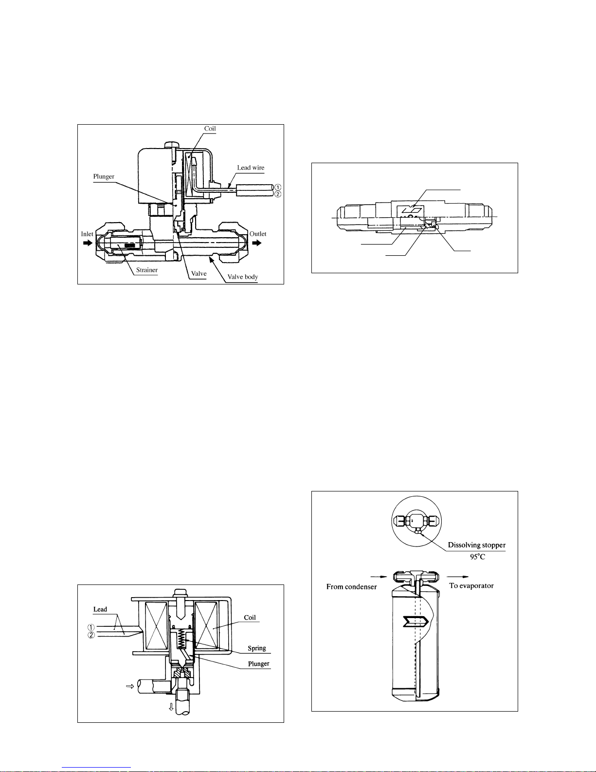
10.5 Electromagnetic valve
(1) Defrost electromagnetic valve
It is installed in order to flow hot gas into the
evaporator side when defrosting.
How to determine defective or not defective:
When continuity of the lead between 1 and 2 is
measured, the coil is normal if there is continuity
and if not, it is defective.
Before the coil is electrified, the temperature at the
inlet and outlet of refrigerant differs. So if the
temperature becomes the same after the coil is
electrified, the plunger is operating normally.
If the temperature differs the plunger is stuck.
Easy way to find out the problem:
When you electrify the coil with your hand
touching the electromagnetic valve, it is normal if
your hand feels a shock as the plunger goes up
with a click sound.
(2) Liquid injection electromagnetic valve
It opens when delivery temperature (at the sensor)
of the compressor becomes more than 125°C,
keeping the delivery temperature from becoming
high.
How to determine defective or not defective:
Same as defrost electromagnetic valve.
Refer to "defrost electromagnetic valve".
10.6 Check valve
It is installed to prevent the refrigerant from flowing
back ward.
How to determine defective or not defective:
Make a judgment by the difference of temperature at
the inlet and outlet of the check valve and replace it if it
is leaking.
10.7 Receiver
It reserves the refrigerant which has been liquefied by
the condenser.
The receiver has a dissolving stopper which will melt
and discharge the refrigerant in order to prevent a
danger due to unusual high temperature.
When the stopper has been melted, replace it with a
new one.
– 15 –
Defrost electromagnetic valve
Liquid injection electromagnetic valve
Arrow mark
Disk
Main valve
Spring
Check valve
Receiver
Page 20
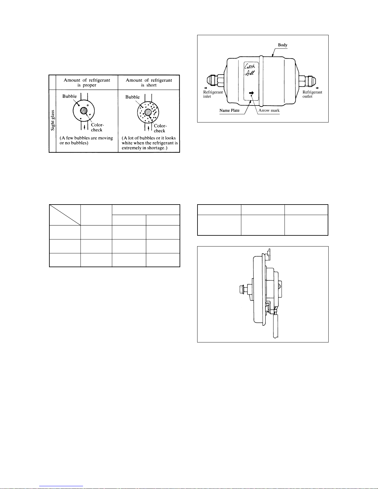
10.8 Sight glass
It can judge the circulating amount of refrigerant and
existence of water in the refrigerant.
If the refrigerant is short, repair the leaking place and
then charge gas.
How to determine existence of water:
Color of a color-check
In case of yellow color, it in necessary to vacuum and
replace the dryer.
10.9 Dryer
Moisture and foreign materials are eliminated from the
refrigerant. If the desiccant (molecular sieve) in the
dryer can not remove moisture (the check color of the
sight glass becomes yellow), replace the dryer
assembly. Also if inside of the dryer is clogged during
operation, there will be a difference in temperature
between the inlet and the outlet, and the outlet side
becomes cool.
When the dryer is replaced, replace it quickly. Here,
when installing the dryer, pay heed to its direction and
install it on the unit with the arrow mark aligned to the
flow of the refrigerant.
10.10 Condenser fan motor
Remarks: The brush can not be replaced
– 16 –
Dryer
Revolution
2100min
-1
Electric current
3.2A
Input
70W
Condenser fan motor
Sight glass
Green
Light green
Yellow
Judgment
Normal
Rather
abnormal
Abnormal
Moisture amount
Refrigerant
temperature 24°C
Refrigerant
temperature 38°C
15 ppm or less
15 ~90 ppm
90 ppm or more
30 ppm or less
30 ~140 ppm
140 ppm or more
Page 21
10.11 Evaporator fan motor
Note: The fan motor is press-fit to the fan.
Replace it as the assembly of the fan.
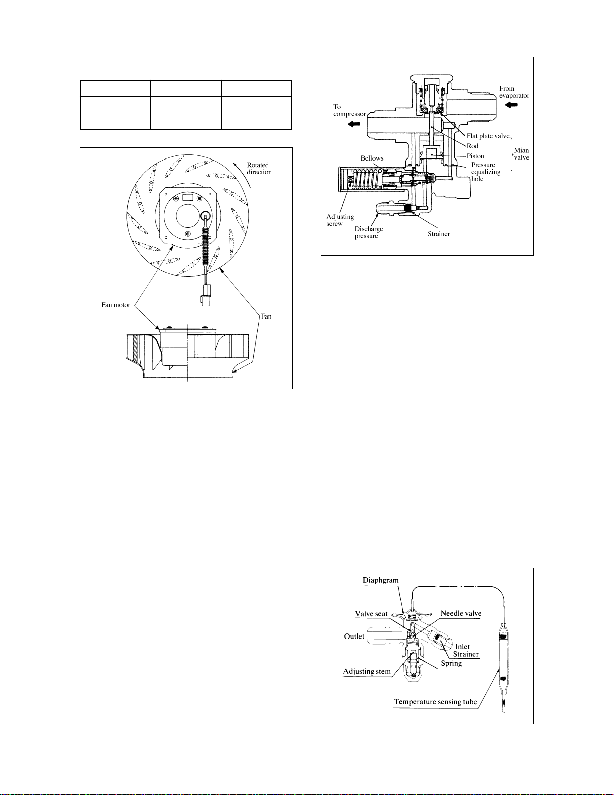
10.12 Multi-function valve
The multi-function valve features the following.
(1) At the abnormally high pressure, the suction
pressure is controlled to allow the unit to operate
without any abnormal stop (high-pressure cutting).
(2) Since the main valve of the multi-function valve is
closed when the unit is stopped, the liquid does not
return. This eliminates a danger of liquid
compression to improve the reliability of the
compressor.
(3) The pressure equalizing hole of the multi-function
valve makes the pressure difference early balanced
soon after the unit is stopped. This will reduce the
starting torque.
Note: (1) Since the multi-function valve was factory-
set at shipment, don't adjust it at the site.
If the adjusting screw is turned, the setting will
become disturbed to cause a poor operation.
(2) When installing the multi-function valve
and connecting the pipe, don't apply any
shock to the multi-function valve.
Otherwise, it will cause gas leakage or
improper operation.
10.13 Expansion valve
The valve detects overheat at the outlet of the
evaporator so that proper amount of refrigerant can
flow into the evaporator, and make an automatic
adjustment.
When adjusting, turn the adjusting screw at a revolution
of 1/4 and then 1/2 little by little, and see how much
heated it is.
– 17 –
Revolution
2000min
-1
Electric current
2.92A or less
Input
70W
Multi-function valve
Evaporator fan motor (Fan assembly)
Expansion valve
Page 22
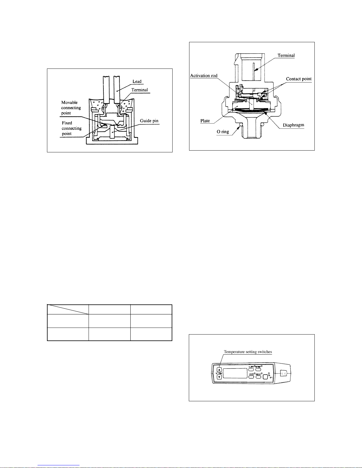
10.14 Defrost thermostat (DTS)
It detects temperature of the evaporator coil and
indicates an end of defrosting.
CUT IN 0 ± 3°C
CUT OUT 8 ± 3°C
Not adjustable
How to determine defective or not defective
Put the defrost thermostat into a household electric
refrigerator and check as you look at a thermometer. It
is normal if there is continuity under 0°C and no
continuity above 8°C.
10.15 Dual pressure switch (DPS)
When the delivery pressure becomes excessively high
or low, it is dangerous. So, the dual pressure switch
(normally close type) is activated to stop the
compressor.
Setting valve MPa (kgf/cm
2
)
CUT OUT CUT IN
2.94 ± 0.2 2.35 ± 0.2
High pressure side
(30 ± 2) (24 ± 2)
0.20 ± 0.02 0.23 ± 0.02
Low pressure side
(2.0 ± 0.2) (2.3 ± 0.2)
Adjustment is impossible.
Judgment whether is proper or not
[High pressure side]
If there is any continuity when the pressure is
2.94MPa (30kgf/cm
2
) or lower during stop and
operation, and there is not when the pressure is
2.94MPa (30kgf/cm
2
) or higher, it is proper.
[Low pressure side]
If there is any continuity when the pressure is
0.20MPa (2.0kgf/cm
2
) or less during stop and
operation, and there is not when the pressure is
0.20MPa (2.0kgf/cm
2
), it is proper.
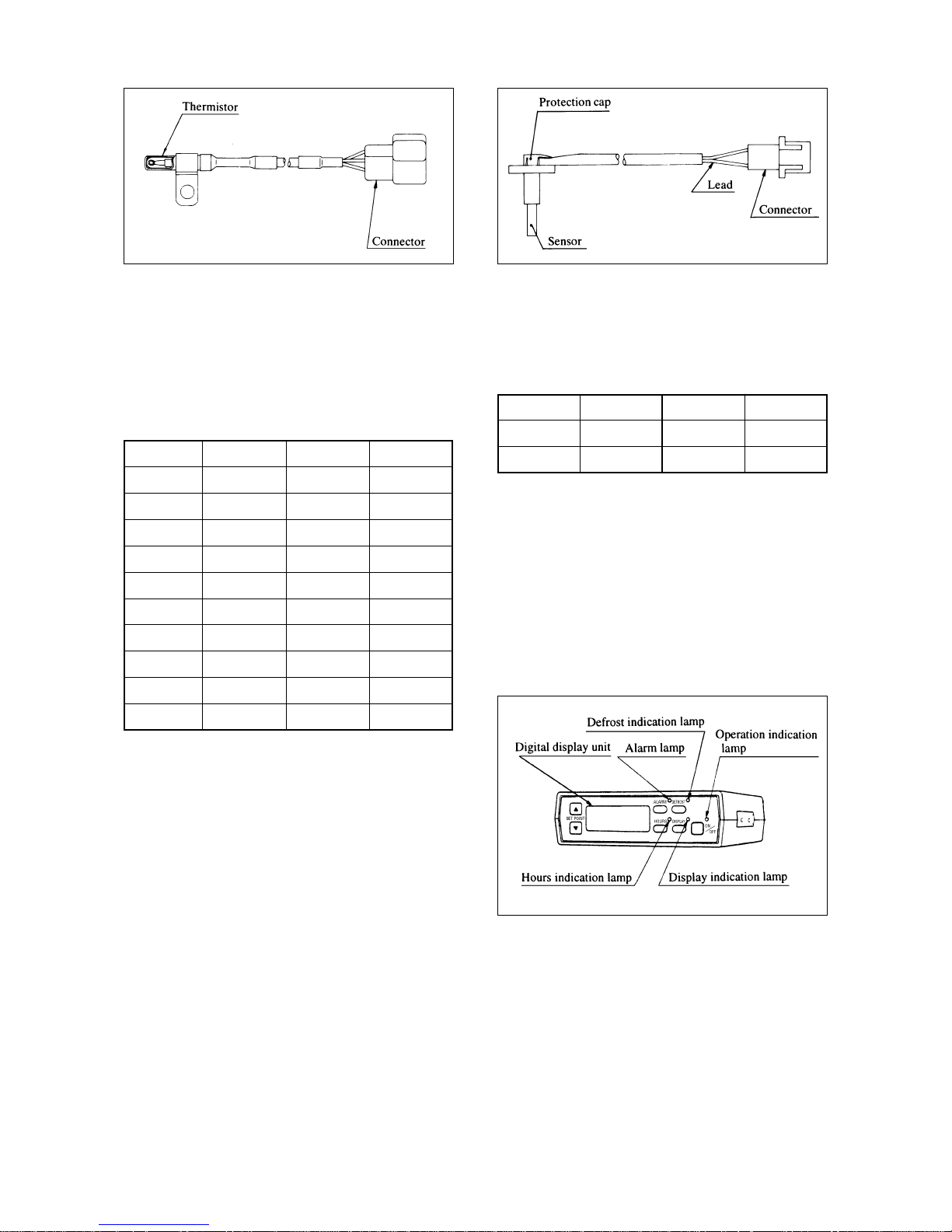
10.16 Storage temperature sensor (TH)
The sensor detects a storage temperature in order to
keep its temperature to an established temperature,
keeping the magnet clutch or the relay "ON" and
"OFF".
Setting of storage temperature is made by the
temperature setting switches of the controller.
– 18 –
Defrost thermostat
Dual pressure switch
Controller
Page 23
How to determine defective or not defective
(a) Measure continuity by removing the connector at
the edge of temperature detection.
(b) Resistance value at the edge of temperature
detection in normal condition.
(Unit kΩ)
°C Rmin. Rnom. Rmax.
-30 25.293 26.316 27.376
-20 15.125 15.572 16.031
-10 9.342 9.524 9.709
0 5.940 6.000 6.060
10 3.810 3.882 3.995
20 2.505 2.573 2.644
25 2.049 2.113 2.179
30 1.687 1.746 1.808
40 1.163 1.213 1.265
50 0.819 0.860 0.903
(c) If the resistance value is widely out of order,
remove it at the edge of the temperature detection
(with lead) and replace it.
(d) If the above resistance value is normal, check the
controller.
10.17 Td sensor (Td)
It detects delivery temperature of the compressor and
stops the refrigeration unit or opens the liquid injection
electromagnetic valve.
• If the delivery temperature becomes more than 125°C,
opens the liquid injection electromagnetic valve in
order to lower delivery temperature.
• If the delivery temperature becomes more than 135°C,
stops the refrigeration unit.
How to determine defective or not defective:
Measure the resistance value by removing the
connector.
Resistance value in normal condition
200°C 0.430kΩ 100°C 5.228kΩ
175°C 0.738kΩ 25°C 80.470kΩ
115°C 3.352kΩ
10.18 Controller
A new controller with a character display function has
been adopted, which enables to set digitally a desired
storage temperature accurately. In addition to it, preoperation inspection for the refrigeration unit can be
made by a simple button operation and a diagnosis at
the time of the unit being defective can also be made
easily.
Display function
• Operation indication lamp
• Defrost indication lamp
• Alarm lamp
• Hours indication lamp
• Display indication lamp
– 19 –
Storage temperature sensor Td sensor
Controller
Page 24
• Inside-container temperature
• Fault display
• Inside-container preset temperature
• Operation times
• Defrost timer
Remarks: As to abnormal indication, refer to page 47.
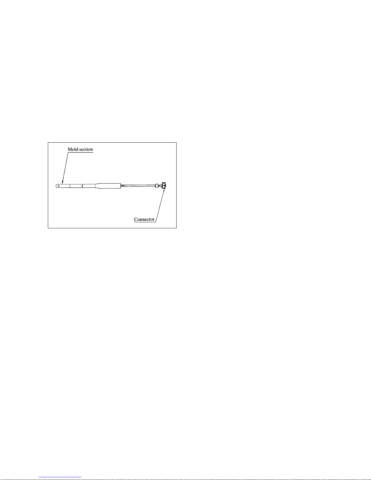
10.19 Drain hose heater (option)
It is electrified when the defrost thermostat is "ON" and
prevent the drain hose from being frozen.
Capacity 6W
– 20 –
Displayed on
the digital
display unit.
Drain hose heater
Page 25
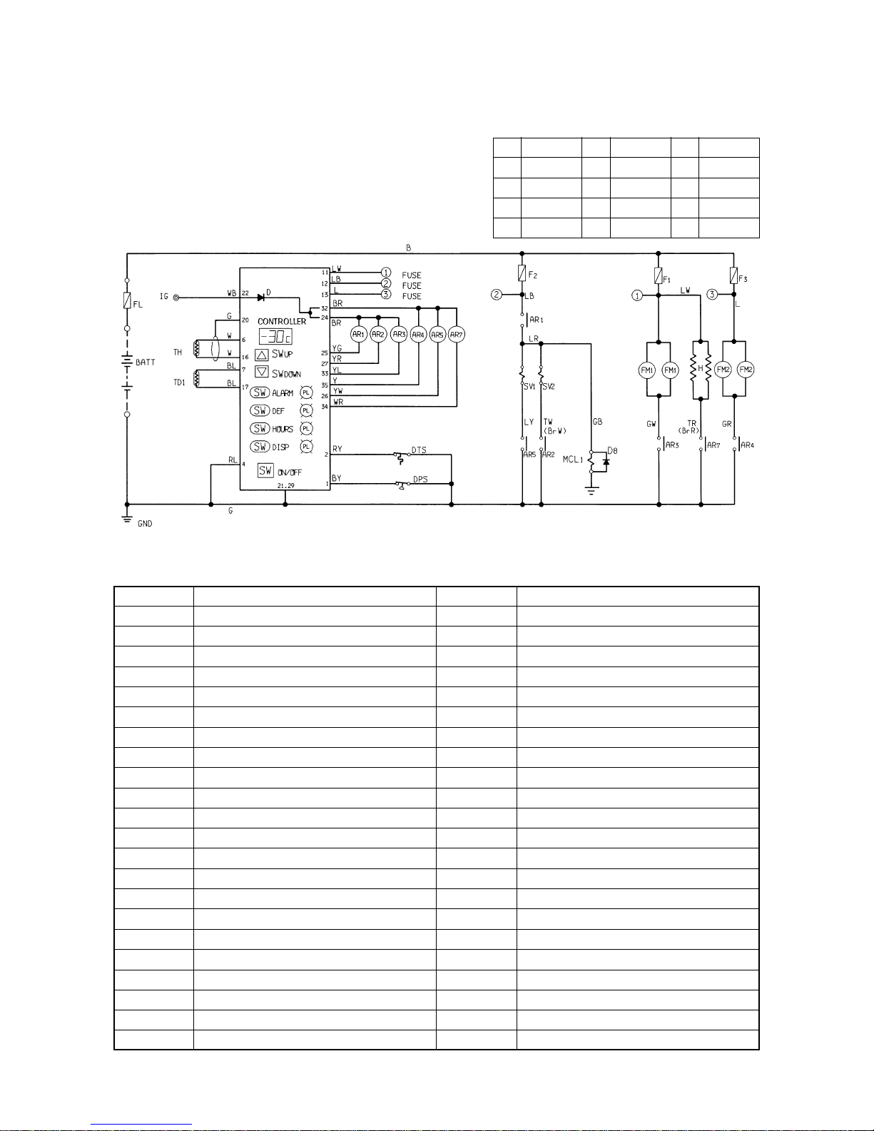
11. Electric wiring diagram
11.1 Sequence diagram
(1) TDJ300D-1L2, TDJ430D-1L2
Remarks: Three FM
1
(evaporator fan motor) are provided on TDJ430D.
– 21 –
Explanation of mark
SYMBOL
SW
UP
SW
DOWN
SW
ALARM
SW
DEF
SW
HOURS
SW
ON/OFF
SW
DISP
PL
ALARM
PL
DEF
PL
HOURS
PL
DISP
TH
DPS
TD
1
DTS
FL
BA TT
IG
NAME
Temperature setting switch (up)
Temperature setting switch (down)
Alarm switch
Defrost switch
Hours switch
Operation switch
Display switch
Alarm lamp
Defrost indication lamp
Hours indication lamp
Display indication lamp
Storage temperature sensor
Dual pressure switch
Td sensor (engine side)
Defrost thermostat
Fusible link
Battery
Ignition terminal
SYMBOL
AR
1
AR
2
AR
3
AR
4
AR
5
AR
7
F
1
F
2
F
3
FM
1
FM
2
H
MCL
1
SV
1
SV
2
NAME
Thermostat relay
Liquid injection electromagnetic relay
Evaporator fan motor relay
Condenser fan motor relay
Defrost electromagnetic valve relay
Drain hose heater relay
Fuse (*1: 15A, *2: 25A)
Fuse (10A)
Fuse (15A)
Evaporator fan motor
Condenser fan motor
Drain hose heater (option)
Magnet clutch (engine side)
Defrost electromagnetic valve
Liquid injection electromagnetic valve
*1: TDJ300D
*2: TDJ430D
Code Wire color Code Wire color Code Wire color
B Black Y Yellow P Pink
W White L Blue V Violet
R Red Br Brown Gy Gray
G Green O Orange Lg Light green
Wire color codes
wire colors are identified by the following color codes.
Page 26
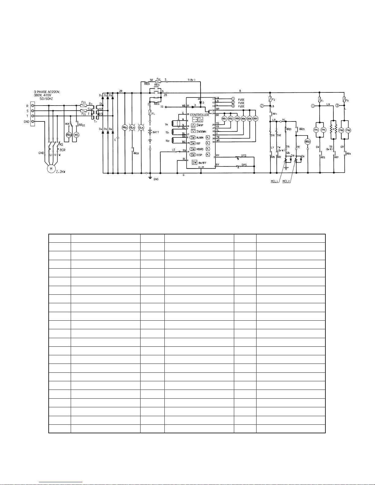
(2) TDJ300D-2L2
– 22 –
Explanation of mark
SYMBOL
SW
UP
SW
DOWN
SW
ALARM
SW
DEF
SW
HOURS
SW
ON/OFF
SW
DISP
PL
ALARM
PL
DEF
PL
HOURS
PL
DISP
TH
DPS
TD
1
TD
2
FL
BA TT
IG
SYMBOL
GL
21
RL
21
F
21
F
22
AR
21
AR
22
AR
23
LS
MS
T
r
D
1, 2, 3
D
4, 5, 6
D
8, 9
C
M
NAME
Temperature setting switch (up)
Temperature setting switch (down)
Alarm switch
Defrost switch
Hours switch
Operation switch
Display switch
Alarm lamp
Defrost indication lamp
Hours indication lamp
Display indication lamp
Storage temperature sensor
Dual pressure switch
Td sensor (engine side)
Td sensor (motor side)
Fusible link
Battery
Ignition terminal
NAME
AC power indication lamp
OCR operation indication lamp
Fuse (3A)
Fuse (5A)
AC-DC transfer relay
Actuator relay
OCR relay
Limit switch (plug cap)
Electromagnetic switch (with OCR)
Transformer
Diode
Diode
Diode
Condenser
Motor
SYMBOL
AR
1
AR
2
AR
3
AR
4
AR
5
AR
7
F
1
F
2
F
3
FM
1
FM
2
H
MCL
1
MCL
2
SV
1
SV
2
NAME
Thermostat relay
Liquid injection electromagnetic relay
Evaporator fan motor relay
Condenser fan motor relay
Defrost electromagnetic valve relay
Drain hose heater relay
Fuse (15A)
Fuse (10A)
Fuse (15A)
Evaporator fan motor
Condenser fan motor
Drain hose heater (option)
Magnet clutch (engine side)
Magnet clutch (motor side)
Defrost electromagnetic valve
Liquid injection electromagnetic valve
Page 27
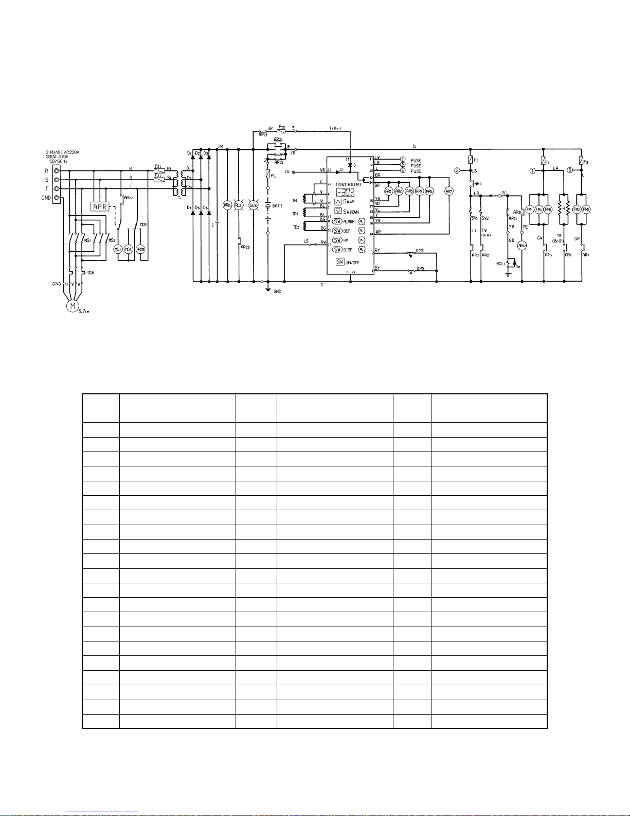
(3) TDJ430D-2L2
– 23 –
Explanation of mark
SYMBOL
SW
UP
SW
DOWN
SW
ALARM
SW
DEF
SW
HOURS
SW
ON/OFF
SW
DISP
PL
ALARM
PL
DEF
PL
HOURS
PL
DISP
TH
DPS
TD
1
TD
2
DTS
FL
BA TT
IG
SYMBOL
GL
21
RL
21
F
21
F
22
AR
21
AR
22
AR
23
LS
MS
T
r
D
1, 2, 3
D
4, 5, 6
D
8
C
APR
M
NAME
Temperature setting switch (up)
Temperature setting switch (down)
Alarm switch
Defrost switch
Hours switch
Operation switch
Display switch
Alarm lamp
Defrost indication lamp
Hours indication lamp
Display indication lamp
Storage temperature sensor
Dual pressure switch
Td sensor (engine side)
Td sensor (motor side)
Defrost thermostat
Fusible link
Battery
Ignition terminal
NAME
AC power indication lamp
OCR operation indiction lamp
Fuse (3A)
Fuse (5A)
AC-DC transfer relay
Actuator relay
OCR relay
Limit switch (plug cap)
Electromagnetic switch (with OCR)
Transformer
Diode
Diode
Diode
Condenser
Antiphase detection relay
Motor
SYMBOL
AR
1
AR
2
AR
3
AR
4
AR
5
AR
7
F
1
F
2
F
3
FM
1
FM
2
H
MCL
1
SV
1
SV
2
NAME
Thermostat relay
Liquid injection electromagnetic relay
Evaporator fan motor relay
Condenser fan motor relay
Defrost electromagnetic valve relay
Drain hose heater relay
Fuse (25A)
Fuse (10A)
Fuse (15A)
Evaporator fan motor
Condenser fan motor
Drain hose heater (option)
Magnet clutch (engine side)
Defrost electromagnetic valve
Liquid injection electromagnetic valve
Page 28

11.3 Explanation of operation (Explanation is made for TDJ300D-2L2)
(1) In case of engine drive
1. Start the engine of a vehicle to be run.
2. Turn the operation switch to "ON".
• Operation indication lamp will light. (green)
• AR
3
(Evaporator fan motor relay) is energized, and FM1(evaporator fan motor) is electrified and then the
evaporator fan turns.
3. When storage temperature is more than the established temperature (the thermostat is "ON").
• AR
1
(thermostat relay) is energized, and MCL1(magnet clutch on engine side) is electrified and then the
condenser fan turns.
• AR
4
(Condenser fan motor relay) is energized, and FM2(condenser fan motor) is electrified and then the
condenser fan turns.
4. When storage temperature is less than 0°C, DTS (defrost thermostat) is "ON".
• The defrost timer starts adding up time.
• AR
7
(drain hose heater relay) is energized and H (drain hose heater) (option) is electrified.
The above procedures make a cooling operation.
Remarks: If the delivery temperature becomes more than 125°C, AR
2
(Liquid injection relay) is energized and
SV
2
(Liquid injection electromagnetic valve) is electrified.
[Less than 120°C ······ non-energized]
– 28 –
A Cooling operation
Page 29

1. In case a storage temperature drops (thermostat "OFF") to an established temperature
• AR
1
(thermostat relay) is dropped out, and MCL1(magnet clutch) is disconnected and then the compressor stops.
• AR4(condenser fan motor relay) is dropped out, and FM2(condenser fan motor) is disconnected and then the
condenser fan stops.
Remarks: The followings are operating even when the unit has stopped with thermostat "OFF".
(1) The evaporator fan is rotating.
(2) In case the storage temperature is less than 0°C (DTS is "ON".):
• Drain hose heater is electrified.
• Defrost timer adds up time.
(3) Operation indication lamp (green) is on.
2. In case the storage temperature has become more than the established temperature (thermostat "ON")
• AR
1
(thermostat relay) is energized, and MCL1(magnet clutch) is electrified and then compressor turns.
• AR4(condenser fan motor relay) is energized, FM2(condenser fan motor) is electrified and then condenser fan
turns.
Storage temperature will be kept at a fixed temperature by repeating the abov e procedure.
– 29 –
B Operation of ON-OFF by thermostat during cooling operation.
Remarks: The following shows a diagram
being stopped by thermostat.
Page 30

1. When defrost switch has been turned on or defrost timer is operating (the timer is built into the controller and is set
in 3 hours for shipment from factory)
• Defrost indication lamp lights. (orange)
• AR
3
(evaporator fan motor relay) is dropped out, and FM1(evaporator fan motor) is disconnected and then
evaporator fan motor stops.
• AR
4
(condenser fan motor relay) is dropped out, FM2(condenser fan motor) is disconnected and then condenser
fan stops.
• AR
5
(defrost electromagnetic relay) is energized, and SV1(defrost electromagnetic valve) is electrified and open.
Defrost operation will start after going through the above procedure.
Remarks: Even if the unit is stopped by thermostat operation, defrost timer will operate or if defrost switch is turned
on, it performers defrost operation.
2. When frost is melted and evaporator coil temperature rises, DTS (defrost thermostat, "ON": 0°C "OFF": 8°C) turns off.
• Defrost indication lamp (orange) turns off.
• AR
3
(evaporator fan motor relay) is energized, and FM1(evaporator fan motor) is electrified and ev aporator f an turns.
• AR
4
(condenser fan motor relay) is energized, and FM2(condenser fan motor) is electrified and condenser fan turns.
• AR5(defrost electromagnetic relay) is dropped out, SV1(defrost electromagnetic valve) is disconnected and closed.
• AR
7
(drain hose heater relay) is dropped out and H (drain hose heater) is disconnected. (It will be electrified
when storage temperature drops and DTS becomes "ON".)
• Defrost timer becomes "OFF". (When storage temperature drops and DTS becomes "ON", it starts adding up time.)
Cooling operation will start after going through the above procedures.
– 30 –
C Defrost operation
Page 31

– 31 –
1. DPS (Dual pressure switch) operates ···· The unit
stops.
High pressure side
OFF : 2.94MPa (30.0kgf/cm
2
)
ON : 2.35MPa (24.0kgf/cm
2
)
Low pressure side
OFF : 0.20MPa (2.0kgf/cm
2
)
ON : 0.23MPa (2.3kgf/cm
2
)
• The alarm lamp lights (red).
• All relays are dropped out.
2. F
1
(fuse) is blown ···· The unit stops.
• The alarm lamp lights (red).
• All relays are dropped out.
3. F
2
(fuse) is blown ···· The unit stops.
• The alarm lamp lights (red).
• All relays are dropped out.
4. F
3
(fuse) is blown ···· The unit stops.
• The alarm lamp lights (red).
• All relays are dropped out.
5. FL (fusible link) is blown ···· The unit stops.
6. TD (Td sensor) operates ···· The unit stops.
("OFF" at compressor delivery temperature 135°C
and "ON" at 125°C)
• The alarm lamp lights (red).
• AR
1
(thermostat relay) is de-energized, MCL
1
(magnet clutch) is disconnected, and the
compressor stops.
• AR
4
(condenser fan motor relay) is de-
energized, FM
2
(condenser fan motor) is
disconnected, and the condenser fan motor
stops.
Remarks: (1) When alarm lamp lights, the defects
will be shown on the display when
alarm lamp is lit, press the alarm
switch, and the defects will be
shown on the display.
DPS operates ························
F
1
is blown ····························
F
2
is blown ····························
F
3
is blown ····························
TD operates ··························
Storage temperature sensor defect
·········································
(2) When pressure and temperature
drops, DPS and TD automatically
operate again.
(The light goes out if the operation
switch is turned "OFF".)
D Operation of protection device
Page 32

(2) In case of motor drive
Remarks: As the operation of the thermostat and defrost is the same with that of engine drive, refer to page 29 and 30.
1. Turn on the power.
• GL
21
(AC power indication lamp) lights.
• AR
21
(AC-DC transfer relay) is energized.
(automatic switch-over from engine drive to motor derive.)
2. Turn on the operation switch.
• Operation indication lamp lights (green).
• AR
3
(evaporator fan motor relay) is energized, and FM1(evaporator fan motor) is electrified and evaporator fan
turns.
3. When storage temperature is more than an established temperature (thermostat is "ON"):
• If AR
1
(thermostat relay) is energized:
When AR
22
(actuator relay) is energized, MS (electromagnetic switch) is energized, which electrifies M (motor)
and the motor turns.
• AR
4
(condenser fan motor relay) is energized, and FM2(condenser fan motor) is electrified and condenser fan
turns.
4. When storage temperature is less than 0°C, DTS (defrost thermostat) is "ON".
• Defrost timer starts adding up time.
• AR
7
(drain hose heater relay) is energized and H (drain hose heater) (option) is electrified.
Cooling operation will start after going through the above procedures.
Remarks: If the delivery temperature becomes more than 125°C, AR2(Liquid injection relay) is energized and SV
2
(Liquid injection electromagnetic valve) is electrified.
[Less than 120°C ······ non-energized]
– 32 –
A Cooling operation
Page 33

1. OCR (Overcurrent relay) operates ···· The unit stops.
• MS (electromagnetic switch) is dropped out, M (motor) is disconnected and the motor stops.
• AR
23
(OCR relay) is energized and RL21(OCR operation indication lamp) lights.
• All relays drop out because power source to the controller is OFF. For re-start, push OCR manual reset button.
Remarks: As for the procedures except for the above, refer to page 31 as they are the same with those of engine
drive.
– 33 –
B Operation of protection device
Page 34

12. Periodic inspection
Perform the periodic inspection for the items required
on the following period.
Write down necessary matters to the check sheet on
page 40.
1. Inspection at the time of installation and test run
2. Monthly inspection
3. Six-month inspection
12.1
Inspection at the time of installation and test run
(1) Check seals of refrigeration unit at the sections
passing through a van wall.
Check if the sealant is processed for sure and no
air goes in.
(2) Check the tubing clamp for adequacy.
Make sure tubing does not vibrate during driving.
(3) Check the drain hose for connection and drainage
and the clamp for adequacy.
(4) Check the belt for tension, degree of parallel
(stick-out of interline) and scratches.
Hold center of the belt and adjust its bending up to
about 7 ~ 10mm.
(5) Check if the belt is touching another parts such as
compressor, pulley, belt, tubing and wiring.
Especially check if abnormal sound is heard from
moving parts.
(6) Check if the mounting bolt is tightened more, if
the refrigeration unit, compressor, compressor
head, magnet clutch, tension pulley, bracket, fan
motor and fan are properly installed, if the unit is
deformed or if truck has scraches on the body.
(7) Check for wrong electrical wiring, clamp, loose
terminal.
(8) Check the service valve is opened of refrigerant
system.
(9) Check refrigerant system, oil and gas leakage,
connection part of tubing and installation of
functional parts.
(10) Abnormal sound and vibration
Check the compressor, magnet clutch, motor, fan
and tubing for abnormal sound and vibration.
(11) Inspection of sight glass
Color of the sight glass is to be green and the glass
has to have no excessive bubbles.
(12) Check starting and stopping of compressor,
magnet clutch and fan by thermostat.
(13) Cooling operation
Check display for temperature indication and
dropping of temperature.
(14) Check defrost for operation.
Check it by turning on manual defrost switch.
(15) Check DPS (Dual pressure switch) for operation.
CUT OUT (high): 2.94MPa (30kgf/cm
2
)
(low): 0.20MPa (2.0kgf/cm
2
)
(16) Check power source wiring (ground wire,
insulation resistance) (Type 2 only)
Note:
Insulation resistance measurement method (AC 3phase circuit only)
Short-circuit the power source terminal (R.S.T or
power source plug pin) and measure the insulation
resistance between the short-circuited section and
the grounded section by an insulation resistance
tester.
(17) Check the motor drive for operation. (Type 2 only)
(18) Check the buzzer for buzzing. (Type 2 only)
(19) Check the instruction manual.
12.2 Daily inspection
Refer to page 36 except the following items.
(1) Implement the checking items about the engine to
be run.
(2) Confirm that there are no abnormal sound and
vibration.
(3) Check if anything is touching the movable places.
(4) Check the compressor belt for tension, wear and
abnormal sound.
(5) Check if the condenser fan and evaporator fan are
turning.
(6) Check if the temperature indication of the display
is proper.
(7) Check commercial power driving equipment
(motor drive)
• Check the power source cord for damage.
Check if the power box cover is firmly fixed.
Check to see no water is in the plug receptacle.
• Check to see the motor is running and if
abnormal sound is heard during operation.
– 34 –
Page 35

(8) During transportation, look at the display from
time to time to see if it keeps and established
storage temperature.
12.3 Monthly inspection
(1) Check the belt for looseness, degree of parallel
(stick-out of interline) and scraches. (bending of
the belt is to be about 7mm ~ 10mm.)
(2) Check if anything is touching to another part.
(compressor, pulley, belt, tubing and wiring)
(3) Clean carefully the refrigeration unit and drain
pipe with soft brush.
The fins will be deformed or damaged if a hard
brush is used.
Note:
(a) Never make a high pressure washing with a
high pressure washing machine as it crushes
its fin.
(b) Never make a steam washing as it raises its
inside pressure unusually high and is
dangerous.
(4) Check the refrigerant sight glass for color and
degree of flash.
Green = Normal
Yellow = Abnormal (water in it)
Lots of bubbles = Insufficient refrigerant
(Replacement of dryer and refrigerant is needed if
water is in it)
(5) Check refrigeration. (Check temperature indication
on the display and high and low pressure power.)
As to high and low pressure power, refer to page
41.
(6) Implement the matters to be taken care of at the
time of periodic inspection as shown on page 38.
12.4 Six-mouth inspection
(1) Implement the checking items required at the time
of installation-test operation and monthly
checking. (excluding a check for mis-wiring)
(2) Check the relay for contact point.
Correct defective contact point due to short circuit.
(3) Carry out the warning items at the time of periodic
inspection listed on page 38.
12.5 Bolt tightening table for each section
(1) Standard tightening torques for flare nuts.
Tightening torque N·m(kgf·cm)
9.8 ~ 19.6 (100 ~ 200)
19.6 ~ 29.4 (200 ~ 300)
29.4 ~ 39.2 (300 ~ 400)
39.2 ~ 49.0 (400 ~ 500)
49.0 ~ 58.8 (500 ~ 600)
(2) Tightening torques of general N·m (kgf·cm)
SS41C S45C SUS304
No mark or 4 or 7 No mark
0.6 ~ 1.0 1.0 ~ 1.5 0.8 ~ 1.0
M3
(6 ~ 10) (10 ~ 15) (8 ~ 10)
1.0 ~ 1.5 2.0 ~ 3.0 2.0 ~ 2.5
M4
(10 ~ 15) (20 ~ 30) (20 ~ 25)
2.0 ~ 2.5 4.0 ~ 5.0 3.4 ~ 4.4
M5
(20 ~ 25) (40 ~ 50) (35 ~ 45)
3.5 ~ 4.4 6.9 ~ 8.3 6.4 ~ 7.8
M6
(36 ~ 45) (70 ~ 85) (65 ~ 80)
8.4 ~ 9.8 17.7 ~ 19.6 16.7 ~ 19.6
M8
(86 ~ 100) (180 ~ 200) (170 ~ 200)
17.0 ~ 19.6 35.3 ~ 40.2 33.3 ~ 38.2
M10
(173 ~ 200) (360 ~ 410) (340 ~ 390)
29.4 ~ 33.3 59.8 ~ 69.6 56.9 ~ 65.7
M12
(300 ~ 340) (610 ~ 710) (580 ~ 670)
47.1 ~ 53.0 96.1 ~ 107.9 91.2 ~ 104.9
M14
(480 ~ 540) (980 ~ 1100) (930 ~ 1070)
73.5 ~ 84.3 156.9 ~ 176.5 142.2 ~ 165.7
M16
(750 ~ 860) (1600 ~ 1800) (1450 ~ 1690)
– 35 –
Applicable
copper pipe
ø 6.35
ø 9.52
ø 12.7
ø 15.88
ø 19.05
Material
Head
mark
Thread
diameter
v
Page 36

12.6 Caution to be taken at the time daily inspection
Instruct users to comply with the following items.
– 36 –
No. Item Contents Care to be taken at the time of operation Anticipated defect Disposition (remarks)
1
2
3
4
5
6
Check for gas
leakage
Washing of
condenser coil
Painting of the
body
Caution to be
taken when not
using for long
Caution to be
taken when the
refrigeration
unit is not
used.
Caution to be
taken when a
refrigerator
truck is used
instead of a
refrigerator.
• Perform this as a daily
inspection as the amount
of refrigerant and water
in the refrigeration can
be checked by sight
glass.
• Prevention of dropping of
heat exchange due to
stain of coil
• Disposition for peeling of
paint on the metal section
of the units which have
been used for long and
for occurrence of rust.
• When not using for long,
decrease the refrigerant
staying in the compressor
and prevent the shaft seal
from running out of oil.
• Do not remove the
compressor belt.
• Preparatory refrigeration,
keeping load in
refrigeration, in case of
using an power-driven
equipment sold at a
market for long instead
of a refrigeration in order
to refrigerate and excess
load at night, prevention
of defroster from troubles
1. Amount of refrigerant
When the amount of refrigerant is short
due to gas leakage, there are lots of
bubbles, and when extremely short, it
looks white (flashing condition)
2. Existence of water
It is normal when the check color is
green, and abnormal when the color is
yellow with more than 140ppm
(refrigerant temperature 38°C) water.
1. The fin will be crushed if it is washed
directly by high pressure water current.
So wash it with brush by water current
from a hose.
1. The rust generated on the painted
surface due to a frying stone or scratch,
will develop without being aware of it.
Rust in early stage can be well prevented
from developing by touch up.
1. When the unit is not used for long,
operate it about 15 minutes once in
every three or four days.
In case of type 2
(Run the engine and motor about 15
minutes once in every three or four days.
1. Do not remove the compressor belt even
if a vehicle is used and the refrigeration
is not used for long.
• In case of using a refrigerator truck for
long instead of a refrigerator, make a
storeroom temperature up to plus degree
once a week and melt the ice frosted.
1. Insufficient amount of
refrigerant
• Defective refrigeration
or no refrigeration
• Rizing of delivery gas
temperature
2. Inflow of water
• Clogging of expansion
valve
• Clogging of receiver
dryer or dryer
1. Stain of condenser coil.
Insufficient operation of
DPS and capacity of
refrigeration
1. Hole and crank in panel.
2. Falling off of panel
1. When the compressor is
not used for long, it will
hold refrigerant liquid in
it, which, when started,
will cause lack of
lubrication and burning
of the compressor. And
also running out of oil in
shaft seal section may
cause leakage of
refrigerant gas.
1. Though shaft bearings
are in the condition of
being fixed by tension of
belt, fretting corrosion
may be generated on
affected place due to
vibration if a vehicle is
run with belt removed.
1. Clogging of drain pipe
due to freezing of
defrosted water or
developing of ice due to
failure of draining may
crush defrost pipe and
cooling coil.
1. Check for leakage and
repair if any, and then
supply refrigerant.
2-1. After recovering
refrigerant and
replacing dryer,
vacuumize it and then
charge a fixed amount
of refrigerant.
2-2. Check and supply
amount of the
compressor in the
same way.
1. Remove and wash stain
of coil as often as
possible.
1. When occurrence of rust
is confirmed, clean the
affected place by sand
paper in early stage and
repair by touch up.
2. Replace the part which
has developed to opening
of hole or crack.
To a servicing shop.
Page 37

– 37 –
No. Item Contents Care to be taken at the time of operation Anticipated defect Disposition (remarks)
7 How to load
into storage
1. Load by giving enough
space so as to be able to
secure circulation of
wing in the storage.
2. When loading and
unloading with door
open, stop the unit.
1. Dimensions shown below are specially
important.
The values in ( )are applicable for
TDJ430D.
1. It may happen that
temperature become
uneven at lower and
upper and front and rear
sides of storage.
2. When the storage door is
opened by circulating
wind, cold air in the
room will be replaced by
outside air, which makes
the storage temperature
rise.
1. Larger size load will
keep storage temperature
from becoming uneven.
2. Space between both sides
of a load is to be more
than 30mm.
Page 38

12.7 Caution to be taken at the time of periodic inspection
– 38 –
No. Item Contents Care to be taken at the time of operation Anticipated defect Disposition (remarks)
1
2
3
4
Tension of belt
Inspection of a
ground wire on
the side of a
vehicle and
maintenance
and
disposition of
harness.
Washing
inside of
refrigerant
circuit and
operation for
cleaning
Refrigerating
machine oil
• Tension of belt between
direct coupled type
engine pulley, idle pulley
and clutch pulley
• Disposition of a ground
wire terminal for the unit
and vehicle chassis
• When compressor is
replaced due to
compressor accident,
check for refrigerant and
oil stain,
and *if necessary, wash
inside of the circuit or
operate for cleaning.
(*) In case of item 4 of
"anticipated defect"
shown on the right
hand column.
• Precaution when using
refrigerating machine oil
for charging to the
compressor.
1. Use tension meter to adjust belt and
provide with an appropriate tension.
2. As a new belt becomes stretched in its
early stage, re-fasten the belt after
operating about 10Hr.
3. After that, check and adjust every
100Hr.
1. Clamp the ground wire terminal and
apply sealer so as not to have its inside
broken during running of a car. Remove
painting on the side of a vehicle.
1.Washing inside of refrigerant
circuit
(1) Enclose HCFC141b and circulate by
another pump.
And after washing inside circuit,
recover HCFC141b and enclose
refrigerant after vacuumizing it.
2.Operation for cleaning
(1) Replace with a new compressor and
after vacuumizing it, charge gas and
perform cooling operation for about
an hour. (For type L specification,
perform defrost operation for about
15 minutes)
(2) After that, recover refrigerant and
replace receiver dryer or dryer .
Replace oil for compressor and once
again vacuumize and charge gas.
The above procedures will prevent a
compressor from becoming
defective again.
1. The refrigerating machine oil (Diamond
Freeze MA32) has an extremely high
absorbency, so work quickly when
handling it.
2. Never use leftover oil. Always dispose
of it.
3. Dispose of any refrigerating machine oil
in the oil can be used, and store it in a
dry state.
1. Too loose
• Slipping of belt
• Dropping of capacity
2. Too tight
• Abnormal pulley
bearing
• Premature wearing of
belt
• Breaking of engine
crank
1. Many defects which will
cause burning of relay,
etc.
2. Breaking of terminal due
to its corrosion
3. Failure of contact
1. No refrigeration
2. Clogging of expansion
valve
3. Clogging of dryer
4. Symptom of compressor
• In case of burning
• In case of remaining oil
having nearly black
color and metal powder
mixed.
• In case of having much
wear and many
scratches on the sliding
surface of cylinder,
piston and rod.
When such symptoms as
above have occurred,
same kind of defect may
happen again soon as it is
possible that the
refrigerant circuit is
stained even after
replacing the compressor.
1. Clogging may occur in
each section if
refrigerating machine oil
exposed to air for a long
time is used.
1. Proper tension
• Direct coupled type
Bending of 7 ~ 10mm
when pushed by 98N
(10kg) force
1. Confirm at each
inspection.
2. Apply sealer to each
terminal of wiring
(except inside of control
box)
1. HCFC141b is a
refrigerant for washing.
1. Do not use refrigerating
machine oil that has been
exposed to air for a long
time.
Page 39

– 39 –
No. Item Contents Care to be taken at the time of operation Anticipated defect Disposition (remarks)
56Parts sold at a
market
Repair to
painted place
• Care to be taken when
parts sold at a market are
used
• Early disposition for
peeling of paint and rust
to metallic place of the
unit
1. Do not use easily parts sold at a market
by only checking sizes and capacity.
1. Rust will increasingly develop into a
secondary damage if left alone. Make an
appropriate repair such as touch up after
removing rust with wire brush, sand
paper, etc., and washing well.
1. In case of tension pulley
bearing, using a bearing
with different sealing
structure (nonecontat seal
type) will soon bring
about a defect even after
replacing with new one.
2. Using fuse with different
characteristic will give no
protection or cause
erroneous operation.
1. Hole or crack in panels
2. Fall off of panel
1. Replace them with
genuine parts.
1. Parts which have been
developed into having a
hole or crack are to be
replaced in order to
prevent and accident of
falling off a running
vehicle.
Page 40

12.8 Check sheet (Installation, test run and periodic inspection)
– 40 –
Customer
Inspection interval
Time
Item
Room temperature ˚C
High pressure
MPa (kgf/cm
2
)
Low pressure
MPa (kgf/cm
2
)
Cooling
inspection
Outside temperature ˚C
Note)
Operate the unit until the
temperature drops to the
designated temperature.
Remarks
Every six
months
Every one
months
Installation
trial operation
Daily inspection
Seasonal inspection
Refrigeration unit
Compressor kit
Vehicle
Model
Serial No.
Model
Serial No.
Model
Serial No.
Inspection items
Inspection seal sections of van where refrigeration unit passes through
Inspection for appropriate wiring clamps
Inspection for secure drain hose connections and adequate clamps
Inspection for belt slack, parallelism (alignment), and damage
Inspection for contact with other parts (compressor, pulley, belt, piping, wiring)
Tightening of installation bolts (refrigeration unit, compressor, compressor head,
bracket, magnet clutch, tension pulley, fan motor, fan)
Inspection for incorrect wiring and for adequate clamps
Inspection for electrical wiring terminal looseness, wiring, sheath damage
Relay contact inspection
Cleaning of refrigeration unit and drain discharge ports
Inspection to check that refrigerant system operation valve is open (gauge manifold inspection)
Inspection for refrigerant system gas leaks (oil leaks)
Inspection for abnormal noise and abnormal vibration
(compressor, magnet clutch, motor, fan, piping)
Inspection of refrigerant sight glass color and flushness
Confirmation of compressor and magnet clutch start/stop, and
condenser fan start/stop with thermostat
Cooling inspection (indication of digital display temperature, high/low pressure inspection)
Confirmation of defrosting operation
Confirmation of dual pressure switch operation
Check of motor operation (operation current measurement) (type 2)
Inspection of power wiring (ground wire, insulation defects) (type 2)
Inspection of buzzer sounding (type 2)
Cleaning of condenser coils
Refrigeration unit painting
Van maker
Refrigeration
unit installation
company
Delivery date
Inspection date
Inspection company
Inspector
Customer’s
signature
Inspection result
Remarks
Page 41

12.9 Pressure table for standard operation
(1) TDJ300D
(2) TDJ430D
– 41 –
10 15 20 25 30 35 40
High pressureLow pressure
MPa(kgf/cm2)
MPa(kgf/cm
2
)
Return air temperature by condenser °C
(Outside air temperature)
Compressor revolution 1800min
-1
2.7 (28)
2.5 (26)
2.4 (24)
2.2 (22)
2.0 (20)
1.8 (18)
1.6 (16)
1.4 (14)
1.2 (12)
1.0 (10)
0.8 (8)
0.6 (6)
0.5 (5)
0.4 (4)
0.3 (3)
0.2 (2)
0.1 (1)
0 (0)
Storage
temperature -18°C
Storage
temperature 0°C
Storage
temperature -18°C
Storage
temperature 0°C
High pressureLow pressure
MPa(kgf/cm2)
MPa(kgf/cm
2
)
10 15 20 25 30 35 40
Return air temperature by condenser °C
(Outside air temperature)
Compressor revolution 1800min
-1
2.7 (28)
2.5 (26)
2.4 (24)
2.2 (22)
2.0 (20)
1.8 (18)
1.6 (16)
1.4 (14)
1.2 (12)
1.0 (10)
0.8 (8)
0.6 (6)
0.5 (5)
0.4 (4)
0.3 (3)
0.2 (2)
0.1 (1)
0 (0)
Storage
temperature -18°C
Storage
temperature -18°C
Storage
temperature 0°C
Storage
temperature 0°C
Page 42

13. Defect and its cause
13.1 Diagnosis of defects on refrigerant system
(1) Table of defect and cause of refrigerant system
– 42 –
High pressure is high.
Low pressure is low.
Low pressure is high.
Bubble can be seen in sight glass.
Compressor becomes frosted.
Compressor will not suck.
Compressor will not maintain sucking pressure
Compressor gives off sound.
No capability of refrigeration
Defrost can not be made.
Overcharge of refrigerant
Shortage of refrigerant
No refrigerant
Return air temperature by condenser is too high.
Clogging of condenser
Return air temperature by condenser is too low.
Air is mixed in refrigeration cycle
Stopping of condenser fan
Clogging of evaporator
Defrost of evaporator is required.
Leakage of compressor delivery valve
Leakage of inlet valve
Excessive circulation amount of refrigeration machine oil
Inadequate tightening of compressor and magnet clutch
Compressor bearing is defective.
Compressor valve plate is broken.
Thermo bulb of expansion valve is defective.
Installation of thermo bulb of expansion valve is defective.
Excessive opening of expansion valve
Excessive closing of expansion valve
Clogging of expansion valve
Liquid back
Low pressure side is clogged.
High pressure side is clogged
Defect
Cause
Page 43

(2) Diagnosis by pressure gauge
Standard pressure value
With the storage temperature at about 0°C
– 43 –
Refrigerant
pressure
High pressure
Low pressure
[Condenser entrance air temperature] + Saturation
pressure of about 14 ~ 16°C
[Cool wind entrance temperature] - Saturation pressure
of about 20°C
No. Pressure Main causes
1
2
3
4
5
6
Both high and low pressure are too high
High pressure is rather low and low pressure is
too high.
High pressure is rather high and low pressure is
too high.
High pressure is almost normal but low pressure
is too low. (Evaporator becomes frosted.)
High pressure is too high but low pressure is
almost normal.
Both high and low pressure is too low.
1. Excessive refrigerant (Accompanied by backing of liquid)
Take out refrigerant up to a fixed amount.
2. Storage temperature is very high.
1. Suction of compressor is defective due to cracking of valve.
(Repair)
1. Excessive opening of expansion valve (Adjust).
2. Contact of expansion valve thermo cylinder to suction pipe is
defective. (Correction)
1. Refrigerant is al little short. (Charge refrigerant)
2. Clogging of receiver dryer or dryer, and expansion valve.
(Replace and adjust)
3. Evaporator fan is defective. (Repair)
1. Condenser is dirty. (Clean)
2. Amount of wind of condenser is short
3. Outside temperature is high
4. Incompressible gas is mixed in the unit. (Vacuumizing, gas
charge)
5. Fan for condenser is defective. (Repair)
1. Refrigerant is extremely short. (Charge refrigerant)
Expansion valve is making a hissing sound.
2. Outside temperature is low. Excessive amount of wind
Page 44

(3) Shortage of refrigeration
– 44 –
Cause of defect Disposition
(1) Wind does not come out much
(a) Evaporator coil is frosted.
(b) Defrost solenoid valve is operating.
(2) There is a chink in the refrigeration van,
which brings in outside air.
(3) A lot of bubbles can been seen in sight
glass and refrigerant is reducing.
(4) Condenser coil is stained.
(5) In case the said items (1), (2), (3) and (4)
are normal,
(a) Expansion valve is clogged.
(b) Expansion valve is opened too much.
(c) Compressor valve is broken.
(a) Change operating time of defrost timer. (Type L only)
(b) Operate manual defrosting.
(c) It is normal if defrost is operating, but if defrost electromagnetic valve
is operating during cooling operation, Check for it. (Type L only)
Check and repair so as to get rid of chink.
Check for gas leakage and supply refrigerant after repair.
Wash by water. However, be careful that fin will be crushed if rubbed by
hard brush
(a) Start engine by connecting a gauge manifold and confirm that
compressor is operating. Through on the high pressure side shows
rather low value, expansion valve, receiver dryer or dryer is clogged
if low pressure side shows lower value than the one shown on page
41.
1) Expansion valve is clogged because water is frozen at the outlet of
expansion valve. So stop operation once, and then after inside ice
being melted, turn compressor again thermostat cylinder in
floating condition. If pressure on low pressure side goes up much
high and after a while pressure lower than the one when operated
normally is shown, it is suspected that water is in the cycle. In case
low pressure gauge will not go up even if thermostat cylinder is
floated, it is suspected that expansion valve is stuck or gas leaks
from thermostat cylinder. (Replace)
2) In case water is in, receiver refrigerant and replace receiver dryer
or dryer. As to vacuumization, use "repeating vacuumization
method", and charge after removing water completely. Also if
receiver dryer or dryer is clogged, low pressure gauge shows lower
pressure than the one when operated normally. And in a extreme
case, tubing followed by receiver dryer or dryer will become
frosted all over. And also in case they are slightly clogged,
temperature differs before and after receiver dryer or dryer.
(Replace)
(b) In case pressure on low pressure side is high and compressor
generates frost at the same time, expansion valve opens too much,
which indicates that refrigerant goes into compressor as liquid
refrigerant. Check for floating of thermostat cylinder. It is suspected
that expansion valve is stuck.
(c) In case there is little difference of pressure between high and low
pressure, either compressor valve is broken or expansion valve
opens too much. As to excessive opening of valve, determine by (b)
above, and as defective compressor valve, check whether or not the
difference of pressure between high and low pressure is normal with
gauge manifold being connected. In case temperature of condenser
will hardly go up, it is suspected that compressor is not compressed.
(check and repair)
Page 45

– 45 –
(4) Abnormal sound can be heard
Cause of defect Disposition
(d) Refrigerant is excessive.
(e) Air is mixed in the unit.
(d) It is a little difficult to determine but tendencies are:
1) High pressure gauge indicates high, that is pressure at operation
indicates higher value than high pressure power shown on page
41.
2) No bubble can be seen from sight glass even if compressor is
turned at high temperature. No bubble still can be seen even if
compressor is turned with the door fully opened when outside
temperature is 35°C or more.
(e) In case a lot of bubbles can be seen from sight glass and
refrigeration is poor, although high pressure gauge indicates high,
air is mixed. As air is lighter than refrigerant, it gathers at the
highest place of the unit and so air purge can not be made.
It is necessary to vacuumize.
Cause of defect Disposition
(1) Installation work is defective.
(2) Metallic sound can be heard from inside of
compressor.
(3) Belt is loose.
(4) Fan is touching.
(5) Compressor liquid is compressed.
Check, repair and increase tightening.
Disassemble inside, check and repair or replace.
Put it on again.
Check and repair.
Check expansion valve and amount of refrigerant.
Page 46

13.2 Charging the refrigerant <R404A>
1. Use the following procedure to charge the refrigerant.
(1) Operation procedure
– 46 –
(2) Evacuation
Connect the high pressure side of the gauge
manifold to the service valve A, and the low
pressure side to the compressor suction operation
valve D (intermediate seat) and the service valve
B with T joint, and do the evacuation at three
places. If any gas leakage is checked with
nitrogen, etc., purge the residual pressure from the
service valve B and do the evacuation.
(3) Gas charge
1 As shown below, place the cylinder upside down
to charge the liquid through the service valve A.
Caution: In case of the orange belt painted
cylinder, charge the liquid, standing the
cylinder in the normal state.
2 Since the multi-function valve is installed on the
system, the pressure is necessary to open the
main valve. Before running the engine slowly,
charge 30 to 50g (amount for one charge hose)
through the suction operation valve D of the
pump in the liquid state.
3 When the temperature rises into the moderate
state (the refrigerant liquid does not flow.), check
the charge amount.
Caution: Take care to prevent charging an
amount beyond the specified value.
4 If the specified amount is not charged, slowly run
the compressor (like idling) to additionally
charge the gas through the operation valve D.
If the specified amount is charged through the
service valve A, it is properly completed as it is.
Caution: Since the pressure of the service valve
A section becomes higher than that of
the cylinder when the compressor runs,
additional charging is impossible. For
additional charging, use the operation
valve D.
For the standard working pressure at the
specified charge amount, refer to page 41.
Condenser
fan motor
Service
valve A
HP takeout tube
Multi-function valve
HP take-out port C
Discharge operation
valve
Suction operation
valve D
Service valve B
Page 47

13.3 Diagnosis of defects on electric parts
(1) Confirmation of trouble with controller
• If the "alarm lamp" lights or flickers, press the "alarm switch" . All errors that are currently occurring will
be displayed as symbols on the "digital display". Confirm the state with the operation switch turned ON.
• Note that error displays or abnormalities in operation may occur due to strong radio waves, etc. In this case, turn
the refrigeration unit off and on once and confirm the operation.
• Always turn the operation switch OFF before inspecting the refrigeration unit.
– 47 –
Alarm
Digital display Remedies Unit state
lamp
(lit)
•
The fuse F2 for the magnet clutch has blown.
Inspect and replace the fuse F
2 in the relay box.
•
The fuse F3 for the condenser fan motor has blown.
Inspect and replace the fuse F
3 in the relay box.
•
The delivery temperature sensor is activated.
Through the sight glass, check for bubbling. If bubbling is
found, check the refrigerant circuit.
•
The fuse F1 for the evaporator fan motor has blown.
Inspect and replace the fuse F
1 in the relay box.
•
The dual pressure switch has functioned.
For high pressure side
(1) Confirm that the condenser fan is rotating, and if it is
not, inspect the wiring for disconnections.
(2) Check whether dirt or mud is adhered on the condenser
coils. Use a brush and water to clean any dirt off.
For low pressure side
The refrigerant runs out. Check for the refrigerant leak, and
refill the refrigerant.
•
Broken wire in room temperature sensor or defective
connection contact.
Check the resistance value and wiring of the room temperature
sensor, and check the connector.
•
Short circuit in room temperature sensor.
Check the resistance value and wiring of the room temperature
sensor, and check the connector.
•
Delivery temperature sensor short circuit
Check the resistance, wiring and connector of the delivery
temperature sensor.
Normal
Unit stops
Unit stops
Unit stops
Unit stops
Unit stops
Unit stops
Operation
continues.
∗11
2
3
4
5
7
ALARM
Room temperature
display
6
(Blinki
ng)
(not lit)
∗2
Note: (1) ∗1 mark indicates that there are multiple abnormalities, and the indications are
done in preferential order of 1, 2 ··· as shown on the above table.
(2) *2 indicates the delivery temperature sensor of the compressor on the
engine side.
indicates the delivery temperature sensor of the compressor on the
motor pack side.
(3) Make sure to replace the fuse with genuine fuse with the same capacity as the
original.
Fuse installation position
Page 48

(2) How to diagnosis defect by controller indication
(The trouble diagnosis is explained for the main
example of Type 1.)
(a) Diagnosis of defect by the alarm lamp "ON"
For checking, press the alarm switch.
1) In case indication on display is
:
Remarks: (1) Measure voltage by body ground wire.
(2) LB, B and BG show the color of wiring.
(3) Refer to terminal number of controller in
page 61.
(4) As to wiring, refer to page 21 ~ 23.
– 48 –
Fuse (F2) is broken.
Replace fuse (F2)
YES
NO
Is battery
voltage measured at the
terminal No.B of
controller?
Replace controller
Contact of fuse holder is
defective.
YES
NO
Is battery
voltage measured at 2nd
side of fuse (F2)?
LB line between controller and
relay box is disconnected or
contact of connector is
defective.
B line between battery and
relay box, between terminal
block and fuse holder is
disconnected or contact of
terminal is defective.
YES
NO
Is battery
voltage measured at 1st
side of fuse (F2)?
YES
Replace fusible link.
Is fusible ink
(FL) is broken?
YES
NO
NO
Page 49

2) In case indication on display is :
3) In case indication on display is :
– 49 –
Fuse (F3) is broken.
Replace fuse (F3)
YES
NO
Is battery
voltage measured at
controller C
terminal?
Replace controller
Contact of fuse holder is
defective.
YES
NO
Is battery
voltage measured at 2nd
side of fuse (F3)?
L line between controller and
relay box is broken or contact
of connector is defective.
B line between terminal block
of relay box and fuse holder is
broken or contact of terminal is
defective.
YES
NO
Is battery
voltage measured at 1st
side of fuse (F3)?
YES
NO
Fuse (F1) is broken.
Replace fuse (F1)
YES
NO
Is battery
voltage measured at
controller A
terminal?
Replace controller
Contact of fuse holder is
defective.
YES
NO
Is battery voltage
measured at 2nd side of
fuse (F1 )?
LW line between controller and
relay box is broken or contact
of connector is defective.
Broken B wire between relay
box terminal block and fuse
holder.
YES
NO
Is battery voltage
measured at 1st side of
fuse (F1 )?
YES
NO
Page 50

4) In case indication on display is :
– 50 –
Check dual
pressure switch
(DPS)
Replace dual pressure switch.
Normal
Voltage
between controller 1
terminal and ground
wire is 0V
Check fan motor and
brush used for
fanmotor.
NO
(Battery voltage)
YES
Is
battery voltage
measured at L line
of fan
L line between fan
motor and relay box
(F3 fuse) is broken or
contact of connector is
defective.
BY and G lines between DPS
and relay box and controller
are broken or contact of
connector is defective.
Controller is defective.
YES
Clean coil.
YES
NO
YES
Is
battery voltage
measured at GR line
of fan
NO
Controller is defective.
NO
YES
YES
Controller Y
terminal is under
0.5V.
NO
YES
• AR4 relay is defective.
• GR line and G line between AR4
and fan motor are broken or
contact of connector is defective.
Abnormal
Condenser coil
is stained.
Condenser
fan motor will
not turn.
Is battery
voltage measured at
at terminal V of
controller?
Page 51

5) or indicated on the digital display
( means the compressor on the engine side, and means the compressor on the motor pack.)
• For the voltage of the TD
sensor, refer to Page 63.
• Terminal Nos. of TD sensor
Engine drive TD
1
: 7G
Motor drive TD2: 8H
6) indicated on the digital display
Press display switch, and or will be displayed.
(1) If the following is displayed when
the display switch is pressed,
• indicates wire breakage
of storage temperature sensor.
• indicates short circuit of
storage temperature sensor. (when
temperature of sensor area is 0°C)
(2) For the resistance value of storage
temperature sensor, refer to Page 63.
∗: Since the power supply is com-
monly used by TD sensor and
storage temperature sensor, the
power supply of storage temperature sensor will be cut off if the
power supply of TD sensor is
short-circuited. Therefore, wire
breakage indication is
displayed for storage temperature
sensor.
– 51 –
Replace controller.
Replace Td sensor.
Check
voltage of
TD sensor.
Replace controller.
Abnormal
Normal
Is 4V
(approx. 90°C)
measured at terminal
No. 7 or 8 of Td sensor?
YES
Inspect and repair connector or
wiring.
Is connector or
line short-circuited?
YES
NO
NO
Replace storage temperature
sensor.
Check
resistance of inside
temperature sensor.
Replace controller.
Inspect connector and wiring,
and repair as necessary.
Abnormal
Normal
NO
Replace Td sensor.
Abnormal
YES
*Check resistance
of Td sensor.
Normal
Is
2.8V measured at terminal
No.6 of controller?
Page 52

(3) Diagnosis of defect other than abnormal indication
(a) In case the unit will not operate even turning the operation switch "ON".
– 52 –
Will operation
indication
lamp light?
NO
YES
NO
Refer to page 54,
compressor will not
turn.
Refer to page 54,
condensor fan motor
will not turn.
Refer to page 53,
evaporator fan motor
will not turn.
Controller is defective.
YES
Is fuse broken?
YES
Replace fuse.
NO
YES
NO
• Line is broken between con troller
and relay box, or contact of
connector is defective.
• WB line between ignition
terminal and controller is broken
or contact of connector is
defective.
• Connecting line between fuse (F
22)
and controller is broken or contact
of connector is defective. (In
caseof motor drive only)
G line is
broken or
contact of
connector is
defective.
NO
YES
Controller is defective.
Unit will not operate with
the operation switch ON.
Note: No.M terminal is only
for motor drive.
Is battery
voltage measured
at terminals and
A,B,C,L and M of
controller?
Are No.K andS
terminals of controller
grounded?
Is battery
voltage measured
at terminals and N
and V of
controller?
Page 53

(b) In case evaporator fan motor will not operate.
– 53 –
Is battery
voltage measured at LW
line of fan motor
conector?
Check and repair motor and
brush.
NO
YES
Is battery
voltage measured at
GW line of fan motor
conector?
LW line between FM1
connector and relay box F1 is
broken or contact of connector
is defective.
BR line between controller and
relay box (AR
3) is broken or
contact of connector is
defective.
• AR3 relay is defective.
• GW and G lines between fan
motor and relay box (AR3) is
broken or contact of connector
is defective.
YES
YES
Is battery
voltage measured at
BR line of AR3 coil?
NO
Controller is defective.
Is under
0.5V measured at W
terminal of controller?
NO
YES
YES
Evaporator fan motor will not
operate.
Page 54

(c) In case compressor will not operate.
(d) In case condenser fan motor will not operate:
In case indication on display is , refer to page 50.
(e) In case thermostat will not operate (will not become ON-OFF)
Refrigeration is defective ···· Refer to page 42, diagnosis of defects on refrigerant system.
– 54 –
Is battery
voltage measured at
GB line of magnet
clutch (engine side)
connector?
Magnet clutch
ground wire is
off.
YES
Is battery voltage
measured at magnet clutch
ground wire?
YES
NO
NO
• AR1 relay is defective.
• GB and LR lines between
magnet clutch and relay box
AR1 are broken or their
contact is defective.
BR line between
controller and relay
box AR
1 is broken or
contact of connector is
defective.
Controller is defective.
Magnet clutch is defective.
Is battery
voltage measured
at BR line of AR
1
coil?
Is under
0.5V measured
at O terminal of
controller?
NO
NO
YES
YES
Compressor will not operate.
Page 55

(f) Defrost operation
1) In case the unit will not defrost.
– 55 –
Is 2 terminal of
controller 0V?
Change time on
defrost timer (Refer
to page 7.)
YES
Check time on
defrost timer.
Normal
NO (In case battery voltage)
Established value of defrost thermostat
ON: 0°C
OFF: 8°C
Normal
Normal if it will
not start defrosting.
Is storage
temperature under 0°C?
NO
YES
2 terminal RY and G lines are
broken or contact of connector
is defective.
• AR
5 relay is defective.
• LY and G lines between SV1
and relay box (AR
5) are
broken or contact of
connector is defective.
Replace defrost
thermostat.
Controller is defective.
Defrost thermostat
Abnormal
(It is not “ON”
under 0°C)
Normal
It will not defrost.
Is battery
voltage measured at LR
line of defrost at LR line of defrost
electromagnetic valve (SV1)
connector?
NO
LR line between AR1 ~ SV1 is
broken or contact of connector
is defective.
YES
NO
Defective electromagnetic
valve (SV1) is defective.
YES
Is battery
voltage measured at
BR line of AR
5 coil?
NO
Controller is defective.
YES
NO
BR line between controller and
relay box AR5 is broken or
contact of connector is
defective.
YES
Is battery
voltage measured at
LY line of defrost
electromagnetic valve
connector?
Is P terminal of
controller under 0.5V?
Page 56

2) In case defrost operation will not recover.
3) In case defrost operation is frequently made.
– 56 –
Defrost operation will not
recover.
Check defrost
thermostat
Abnormal
(It will not become
“OFF” over 8°C)
Replace defrost thermostat.
2 terminal RY line of
controller is short-circuited
and grounded.
Normal
Defrost operation is frequently
made.
Check timeon
defrost timer.
Abnormal
Change time of defrost timer.
Refer to page 7.
Controller is defective.
Normal
Remarks: If air pressure switch
(optional) is installed, check the air
pressure switch.
Page 57

(g) In case drain hose will freeze.
– 57 –
Is battery
voltage measured at LW
line of drain hose heater
connector?
Drain hose heater is defective.
NO
YES
Is battery
voltage measured at BrR
line of drain hose heater
connector?
LW line between fuse (F1) and
drain hose heater is broken of
contact of connector is
defective.
BR line between controller and
relay box AR7 is broken or
contact of connector is
defective.
• AR7 relay is defective.
• BrR and G lines between
drain hose heater and relay
box (AR7) are broken or
contact of connector is
defective.
NO
Refer to page 55, defrost
operation.
Is defrost operation
normally made?
NO
YES
YES
Is battery
voltage measured at BR
line of AR7 coil?
NO
WR line of AR7 coil is broken
or defective.
Is
WR line of AR7 coil
under 0.5V?
NO
(Battery voltage)
YES
YES
Drain hose will freeze.
Page 58

(h) In case of motor drive
Only the items different from the previous ones are written here.
1) In case evaporator fan will not turn.································································· Refer to page 53.
2) In case condenser fan will not turn.·································································· Refer to page 54.
3) In case thermostat will not operate.·································································· Refer to page 54.
4) Defrost operation.·································································································· Refer to page 55.
5) In case drain hose will freeze.············································································ Refer to page 57.
6) In case the unit will not operate even if the operation switch is turned on.
– 58 –
Is fuse (F22)
broken?
NO
Replace fuse (F22)
Will AC
power source
indication lamp
(GL21) light?
YES
NO
YES
It will not operate even if the
operation switch is turned on.
Is abnormal
indication lamp "ON"? (OCR
operation indication
lamp)
YES
Refer to page 60
"OCR operation".
NO
Is 3-
phase 220V (60Hz),
380V (50/60Hz), 415V (50Hz)
measured at power box
RST
?
NO
• Check voltage on
breaker side.
• Power source cord is
broken or contact is
defective.
YES
Is fuse (F21)
broken?
YES
Transformer is
defective.
Replace fuse (F
21).
NO
NO
YES
• AR21 relay is
defective or coil 2R
of relay and G line
are broken.
Is AR21 relay
energized?
Will operation
lamp light?
NO
YES
As to the following items,
refer to page 52, (3)(a)
Is or 24V
measured between 2R
of transformer secondary
side and G line?
Page 59

7) In case compressor will not turn.
– 59 –
• Defective AR22 relay
• Line breakage or poor contact on 7E
line or GND line of power box
terminal block 7C to AR22 coil 7E line
• MS
1 or MS2 solenoid switch is
defective.
• Line breakage or poor contact on MS1
or MS2 solenoid switch coil R3 or R4,
or S line (including )
Inspect and repair motor.
Is AR
1 or relay excited?
NO
YES
YES
BR line, wire breakage or poor
connector contact between
controller and relay box (AR
1)
Is 24V measured
at AR
1 coil BR line?
NO
YES
Defective controller
• Defective AR1 relay
• LR line breakage or poor connector
contact on the way of AR22 coil (7E) to
power box terminal block 7CE, 7C to
relay box AR1
Is 0.5V
or less measured at
terminal No.O of
controller?
NO
Is AR22 relay
excited?
NO
Is electromagnetic
switch MS1 or MS2
excited?
NO
YES
YES
Compressor does not run.
Page 60

8) OCR (over-current relay) operation indication lamp lights.
– 60 –
Is 3-phase
220V (60Hz), 380V
(50/60Hz), 415V (50Hz) measured at
power source box
RST ?
RSTlines are
broken or contact is
defective.
UVW
lines are broken
or contact is defective.
NO
YES
Is
3-phase 220V (60Hz),
380V (50/60Hz), 415V (50Hz)
measured at
RST
of MS1 or MS2
electromagnetic switch
primary
• Breaker is defective.
• Power source cord is
broken or contact is
defective.
Contract point of MS1
or MS2
electromagnetic
switch is defective.
Check motor and repair.
• Check operation electric
current (15A).
• Setting or OCR is defective if
it operates under the above
current.
NO
Check OCR operation
Abnormal
YES
Normal
OCR is defective.
NO
YES
Is
3-phase 220V
(60Hz), 380V (50/60Hz), 415V
(50Hz) measured at UVW of MS
1 or MS2
electromagnetic switch
secondary side?
NO
Is 3-phase
220V (60Hz), 380V
(50/60Hz), 415V (50Hz) at terminals
UVW
of
motor side?
NO
YES
YES
OCR operation indication lamp
lights.
Note: For re-operation push
manual reset button.
Note: Operate and check.
Are OCR terminals
and electrified?
Page 61

(4) Inspection of controller board
(a) Cautionary points for handling the printed-circuit board
1) When taking the board, prevent touching any pattern or part with hand.
To take the board, pinch it at both sides with hand.
2) Prevent touching the board with hand which oil or similar sticks to.
3) Prevent applying any load to the parts on the board with hand or similar.
4) Be sure to prevent any shock which is caused by drop or similar.
5) Prevent water from splashing on the board due to rain or similar.
6) Prevent handling any area where static electricity generates (dry area, room laid with carpet or similar and so on).
7) To temporarily put the board, store it, wrapping the aluminum foil, conductive gloves, etc.
(b) Input/output connector pin numbers
Input/output connector pin assignment list
– 61 –
1
2
3
4
5
6
7
8
9
10
11
12
13
14
15
16
17
18
19
20
DPS
DTS
APS
LPS1
LPS2
TH
TD1
TD2
Spare thermo sensor
Test mode
FUSE1
FUSE2
FUSE3
LS
OCR
Temperature sensor reference
Temperature sensor reference
Temperature sensor reference
Temperature sensor reference
Ground
Sensor
Sensor
Sensor
Sensor
Sensor
Sensor
Sensor
Sensor
Sensor
For check
Sensor
Sensor
Sensor
Sensor
Sensor
Voltage output
Voltage output
Voltage output
Voltage output
Sensor
21
22
23
24
25
26
27
28
29
30
31
32
33
34
35
36
Ground
Ignition
Full-wave rectification
Relay common
AR1
AR5
AR2
AR6
Ground
Ignition
Full-wave rectification
Relay common
AR3
AR7
AR4
Controller (ON/OFF) output
Power
Power
Power
Voltage output
Load
Load
Load
Load
Power
Power
Power
Voltage output
Load
Load
Load
Load
Page 62

– 62 –
(c) Controller inspecting procedure
∗1: For other voltage than 0.5V, refer to TH (storage
temperature sensor) conversion table (P.63).
∗2: For other voltage than 0.5V, refer to TD (Td sensor)
conversion table (P.63).
∗3:
Note: 1)
Car battery supply means that ignition switch is on.
2) AC power supply means that commercial power is
supplied from AC plug.
3) Unit operation means that car battery or AC power
supply unit are on.
• Measure voltage between ground (terminal 20) and
measured terminal.
• Though commercially available tester is applicable for
check, use the tester whose tester rod is cut to sharp.
(Approx. 1mm dia.)
Output relay names
Power supply line breakage
0V
Short circuit from pin M
Normal: 24V
}
Power supply line breakage
0V
Short circuit from pin NO
Normal: Battery voltage
}
Fuse line breakage: 0V
Normal time: Battery voltage
Relay ON : 0V
Relay OFF: Battery voltage
Relay ON : 0V
Relay OFF: Battery voltage
Relay ON : 0V
Relay OFF: Battery voltage
High/low pressure abnormal: 0V
High/low pressure normal:
Battery voltage
Defrost sensor on the low temp. side: 0V
Defrost sensor on the high temp. side:
Battery voltage
Short circuit to GND: 0V
Normal, sensor line
breakage : 5V
Normal: 0V
Normal temperature (15°C):
Approx. 2V
Abnormal
Sensor short circuit : 5V
Sensor line breakage: 0V
Normal time (90°C): Approx. 4V
Abnormal
Sensor short circuit : 5V
Sensor line breakage: 0V
Harness line breakage
Not connected.
0V
Nomral: Battery voltage
}
Normal: 0V
Harness wire breakage
Abnormal SW
}
Battery
voltage
∗1
∗2
∗3
8°C ± 3 (high pressure side)
0°C ± 3 (low pressure side)
Check terminal
1345OPQRWXYZ
267890FGHILN
TV
DMU
ABC
JKL
Inspection conditions
Unit operation
Car battery supply
Unit stop
AC power supply
Unit stop
Always
Car battery
AC power supply
}
Both are
not
provided.
AR
1
AR
2
AR
3
AR
4
AR
5
AR
7
Thermostat relay
Liquid injection electromagnetic relay
Evaporator fan motor relay
Condenser fan motor relay
Defrost electromagnetic valve relay
Drain hose heater relay
Page 63

(d) Storage temperature sensor resistance and voltage as reference
(e) Td sensor resistance and voltage as reference
– 63 –
Temperature (°C)
-30
-25
-20
-15
-10
-5
0
5
10
15
Resistance (kΩ)
26.316
20.155
15.572
12.131
9.524
7.533
6.000
4.811
3.882
3.154
Voltage (V)
4.187
4.004
3.795
3.564
3.313
3.050
2.779
2.509
2.246
1.995
Temperature (°C)
20
25
30
35
40
45
50
Resistance (kΩ)
2.573
2.113
1.746
1.451
1.213
1.019
0.860
Voltage (V)
1.759
1.543
1.349
1.175
1.022
0.888
0.772
Temperature (°C)
0
10
20
30
40
50
60
70
80
90
100
Resistance (kΩ)
263.1
161.2
101.4
65.34
43.09
29.01
19.91
13.92
9.892
7.139
5.228
Voltage (V)
4.952
4.929
4.894
4.842
4.769
4.669
4.535
4.364
4.152
3.900
3.611
Temperature (°C)
110
120
130
140
150
160
170
180
190
200
Resistance (kΩ)
3.881
2.916
2.220
1.707
1.327
1.041
0.824
0.658
0.530
0.430
Voltage (V)
3.295
2.962
2.628
2.300
1.993
1.710
1.458
1.237
1.047
0.884
Page 64

– 64 –
14. Method to select a model with jumper cable
(1) The following functions are selectable with the jumper cables on the circuit-printed board.
(2) Jumper cable installation position
1 Model selection jumper cables J11, 12
3 Heating selection jumper cables J3
Jumper cable is set.:
Refrigerant heating is invalid.
Jumper cable is not set.:
Refrigerant heating is valid.
2 Refrigerant selection jumper cables J21, 22
4 FM
1
(evaporator) switch jumper cable J4
Jumper cable is set.:
FM
1
ON when thermo is off.
Jumper cable is not set.:
FM
1
OFF when thermo is off.
No.
1
2
3
4
Item
Model selection
Refrigerant selection
Heating selection
FM1switch
(evaporator fan)
Jumper cable No.
J11, 12
J21, 22
J3
J4
Description
H, M, L
R22, HFC-134a, R401B, R404A
Refrigerant heating: Valid/invalid
When compressor is off, evaporator FM
1
ON/OFF switch is at the
evaporator FM
1
ON as standard.
Applicable temperature
L -30 ~ 25°C
M -20 ~ 25°C
H -5 ~ 25°C
(M) -20 ~ 25°C
J11
Set.
Set.
Not set.
Not set.
J12
Set.
Not set.
Set.
Not set.
Remarks
—
—
—
Regarded as M selection
Refrigerant selection
R22
HFC-134a
R401B
R404A
HFC-134a
R401B
J21
Set.
Set.
Not set.
Not set.
J22
Set.
Not set.
Set.
Not set.
Remarks
—
—
—
Regarded as HFC-134a,
MP66 selection.
Page 65

15. REFRIGERANT SATURATED PRESSURE TABLE (R404A)
– 65 –
Temperature (°C)
Saturated pressure kPa (kgf/cm2)
-50
-48
-46
-44
-42
-40
-38
-36
-34
-32
-30
-28
-26
-24
-22
-20
-18
-16
-14
-12
-10
-8
-6
-4
-2
0
2
4
–19.2 (144.0mmHg)
–10.6 (79.5mmHg)
–1.3 (9.8mmHg)
9.8 (0.1)
19.6 (0.2)
29.4 (0.3)
39.2 (0.4)
58.8 (0.6)
68.7 (0.7)
88.3 (0.9)
98.1 (1.0)
117.7 (1.2)
137.3 (1.4)
156.9 (1.6)
176.5 (1.8)
196.1 (2.0)
225.6 (2.3)
245.2 (2.5)
274.6 (2.8)
304.0 (3.1)
333.4 (3.4)
362.9 (3.7)
392.3 (4.0)
431.5 (4.4)
460.9 (4.7)
500.1 (5.1)
539.4 (5.5)
578.6 (5.9)
Temperature (°C)
Saturated pressure kPa (kgf/cm2)
6
8
10
12
14
16
18
20
22
24
26
28
30
32
34
36
38
40
42
44
46
48
50
52
54
56
58
60
627.6 (6.4)
666.9 (6.8)
715.9 (7.3)
764.9 (7.8)
814.0 (8.3)
872.3 (8.9)
921.8 (9.4)
980.7 (10.0)
1049.3 (10.7)
1108.2 (11.3)
1176.8 (12.0)
1245.4 (12.7)
1314.1 (13.4)
1392.5 (14.2)
1461.2 (14.9)
1549.5 (15.8)
1627.9 (16.6)
1716.2 (17.5)
1804.4 (18.4)
1892.7 (19.3)
1990.7 (20.3)
2088.8 (21.3)
2196.7 (22.4)
2294.8 (23.4)
2412.4 (24.6)
2520.3 (25.7)
2638.0 (26.9)
2765.5 (28.2)
Page 66

16. INSTALLATION PROCEDURE
16.1 Cautionary points during installation
(1) Be absolutely sure to keep dust and moisture from
entering the piping of the refrigeration unit.
Carry out the connecting of separate type of piping
under a roof, and avoid a rainy or windy day and
outdoor work as much as possible.
(2) When glazing, pass N
2
(nitrogen) gas through the
piping in order to keep it from oxidation.
(3) Pressurize with nitrogen gas before evacuating.
(4) It is desirable to evacuate the system under the
ambient temperature of 10°C or more for more
than 60 minutes. The degree of evacuation should
be –0.1 MPa (750mmHg) or more. In order to
check for leakage, leave it for 5 minutes, and there
is no leakage if it keeps –0.1 MPa (750mmHg).
(5) Put a cover or protector to the piping which sticks
out from the lowest tip of the body or the one
which is placed where it can be easily hit by stones
scattered by the wheel of the vehicle.
(6) Select a place of 80°C or less ambient temperature
for wiring routing.
(7) Clamp the cable at 500mm or less intervals to
avoid unnecessary sags. Use the clamp matching
to the thickness of the harness. And be sure that it
does not slide or pull out when slightly pulled.
Also be sure that the tip of the clamp does not cut
into or crush the harness.
(8) As for wiring under the floor or exposed to
splashing water, set up a trap to prevent the
connector of the unit terminal harness from drop
of water.
(9) Clamping of pipe and harness
(10) As for installation of the controller, select a place
strong enough to hold it. (Installation on plastic
section may cause damage to the unit.)
(11) Thermally insulate the low-pressure pipe.
(12) Adjust the installation position of the bracket, etc.
to align the engine and compressor (magnetic
clutch) at the deviation angle of 0.5 degrees or
less.
(13) Route the high-/low-pressure hoses with care to
consider the three-dimensional dislocation of the
compressor as 15mm in each direction in order to
prevent them from interfering with each other.
– 66 –
Page 67

16.2 Cautionary and requested points during installation
– 67 –
No. Item Explanation Precaution for service Possible failure Corrective action (Remarks)
1
2
3
4
5
Direct coupled
type unit
Pulley
alignment
Route of
compressor
hoses
Surrounding
temperature of
compressor
hose
Refrigerant
piping
Low pressure
piping
(Excluding the
hose)
• When installing the
compressor with the
bracket on the vehicle's
engine, adjust the pulley
alignment between
compressor and engine.
• Since the engine vibrates,
install a hose which
absorbs vibration of the
installed compressor.
• Influence of engine heat
on the compressor hose
• Penetration of moisture
• Penetration of dust
• Be most sure to keep
moisture and dust from
entering the piping in
order to avoid the
refrigerant cycle from
being damaged by them.
• Insulate from heat the
piping from the
evaporator outlet to
sucking pipe of the
compressor. (excluding
hose)
• Branch the pipe of Type
2.
1. Adjust the misalignment to 0.5 degrees
or less. For visual check, tighten the
string.
2. Adjust the tension of the belt with the
tension gauge.
1. Since the compressor may vibrate
approx. 15mm upward/downward and
leftward/rightward, prevent the
surrounding parts from interfering with
each other.
Install the distance rubber near each
part.
2. Bend the hose at the largest possible
curve.
1. Route the hose at the surrounding area
of 80°C or less.
If it is inevitably routed near the exhaust
pipe, install the protector to suppress the
surface temperature to 80°C or less.
1. Work on piping connection under a roof,
avoiding a rainy day.
2. Because copper dust may enter the pipe
from its cut and flared area, perform air
blow (N2 blow) after processing.
3. Don't place piping materials (copper
pipe) on the floor, ground etc, where it is
dusty.
4. When glazing, pass N2 gas into the
piping.
5. Perform evacuation for more than 60
minutes, and reaching of evacuation
should be over –0.1MPa (750mmHg).
6. Don't use the copper pipe which has
been left alone for long and inside of
which is rusted.
1. Pass the low pressure pipe thru the heat
insulated tube.
2. Apply vinyl tape on the connected area
of the tube.
3. Make the route of the piping as short as
possible.
4. Use the branch pipe specified by our
company.
1. Abnormal wear of V belt
2. Trouble of idle pulley
3. Abnormal seal of
compressor shaft
1. The hose is holed.
2. The flared area of the
ferrule is cracked.
3. Poor cooling results from
gas leakage.
1. The hose is holed.
2. The hose is punctured.
3, The ferrule gets off from
the hose.
1. Clogging of water and
dust in the expansion
valve and, clogging of
the dryer.
1. Rising of sucked gas
temperature
Rising of delivered gas
temperature
Early deterioration of
compressor oil
Breaking of compressor
2. Oil is unevenly
distributed.
1. Recondition, adjust or
replace the bracket.
2.
—
3. Replace the compressor.
1. Add the stay for fixture.
2. Add the distance rubber.
1. Change the route of the
hose.
2. Manufacture the heat
protector of aluminum
plate or similar.
1. Investigation of
abnormality on no
freezing reveals that
many of the causes are
due to sticking of copper
dust.
2. Perform evacuation after
applying pressure in
order to check for gas
leakage from glazed area,
etc. To check for leakage
after glazing, leave the
pipe alone for 5 minutes
to maintain –0.1MPa
(750mmHg).
3. Plug the cut of the
refrigerant piping.
1. Apply insulation tube to
the low pressure piping
in order to keep the
sucked gas temperature
from rising.
Page 68

– 68 –
No. Item Explanation Precaution for service Possible failure Corrective action (Remarks)
6
7
8
Clamp
mounting for
pipe and
harness
Setup of pipe
cover
Wire harness
(electrical
wiring)
• The pipe, harness clamp
or pipe cover is fastened
on the body with screws.
• To protect the pipe and
harness from ice, snow
and flying stone.
• To install pipe cover in
order to improve
appearance.
• Wiring process
connecting relay box,
controller, refrigeration
unit and magnet clutch.
1. When the screw hole for the clamp is
drilled to the body, be sure to coat sealer.
t is recommended that seal will be
swelled out when the screw is tightened.
And don't clamp it together with the
high pressure pipe.
1. Install pipe cover when the pipe is stuck
out from the lowest tip of the chassis
and body or when the pipe is passed thru
the place where the stones scattering
from the wheels of the vehicle can easily
hit it.
2. Use sealer when screws are driven.
1. Before wiring works, disconnect the
battery terminal
2. Take care of polarity of battery wiring.
3. Select a place of 80°C or less
atmospheric temperature for wire
routing.
4. Clamp cable at 400 mm or less intervals
to avoid unnecessary sags.
5. Don't clamp together with the high
pressure gas pipe.
6. Use the clamp according to the thickness
of the harness. And when pulled lightly,
it should not be slid or pulled out. Also
be sure that the tip of the clamp does not
bites the wire harness or crush it. Clamp
the harness to the convenient direction.
1. Unless blocked by sealer,
water infiltrates into the
insulated material of the
body thru the clearance
to cause no-cooling.
2. The seal plays the role of
preventing the screw
from loosening.
1. Refrigerant leakage from
the cracked pipe and
many abnormalities
generated from the
refrigerant leakage. In the
worst case, the
compressor will be
broken.
1. If it is energized during
working, it will lead to
short circuit troubles, etc.
2. If the polarities (+) and (-)
are reversely connected,
the electrical parts will be
damaged (burnt).
3. Cable sheath may be
subjected to damage or
fire.
4. Interference with other
equipments
5. Temperature of high
pressure gas pipe
becomes high, causing
damage to the cover and
fire.
6. Broken wire and
effective contact
1. No remedy for the body
which has sucked water.
1. Verify that the battery
terminal is disconnected.
2. Replace the damaged
part.
3. Avoid placing it near the
engine exhaust pipe and
high pressure.
4.
5. Clamp the wire harness
alone.
6.
Holding of body, etc. by
screw
Page 69

– 69 –
No. Item Explanation Precaution for service Possible failure Corrective action (Remarks)
910Chassis
mounting and
supporting
process of
ground cable
Countermeasu
re for the
passing hole
on the van
• Treatment of grounding
wire terminal for unit
grounding wire and
battery grounding wire
onto the vehicle chassis.
• Rain water is prevented
from entering the van,
and the refrigerating
capacity is prevented
from dropping.
7. When wiring is made under the floor or
at a place where rain water splashes, set
up a trap on the straight line so as to
prevent water drop from entering the
connectors of connecting equipments.
8. Be sure to use the specified cables
(thickness and sheath) for wiring.
9. Use the compression terminal or solder
type terminal to connect the cable.
(Solder onto caulking section of crimp
terminal. Hand-twisting and tape
retaining alone are prohibited.)
10. Check the electrical wiring for
interference with any vibratory object
on the way.
11. Insert the connector with lock until it
makes "click" sound. Here, do not
tighten the connector lock with a flat.
12. When installing the connection harness
in the box later, securely seal the
through hole of the box.
13. When using the closed end type
connector outside the box, sufficiently
seal it with sealer.
1. The terminal area is clamped and sealer
coated to prevent the ground cable from
suffering of being internally broken
owing to vibration during car running.
2. Remove paint from the chassis side.
1. If any hole is produced on the van side
or any clearance is produced on the
passing-thru hole (unit mounting bolts,
refrigerant pipe, electric wiring, drain
hose, etc.) in the outfitting process, close
the hole or clearance by coating sealer.
7. Defective contact due to
generation of rust and
broken wire.
8. Unit may be subjected to
fire owing to heating or
sheath thermal damage
which is caused by
insufficient wire capacity.
9. Unit may be subjected to
fire owing to heating and
firing caused by increase
of the contact resistance.
10. Fire may happen on the
damaged sheath of
cable.
11. The connector may be
removed by vibration.
1. Many defects resulting in
burning of alternator,
relay, etc.
1. Rain water enters the van
through the thru-hole or
clearance, and the
thermal insulator is
moistened.
2. Thermal load enters
through the clearance of
the thermal insulator and
is moistened to cause
poor cooling.
7.
8. 9. Observe the electric
wiring standards.
(Neglection is
prohibited. It has been
reported that fire
actually happened
owing to the
neglection.)
10. Clamp cable securely.
Select the cable
connection area which
is free from oil or fuel
sticking.
1. Verify that the hole
clearance is wholly and
securely sealed.
Page 70

– 70 –
No. Item Explanation Precaution for service Possible failure Corrective action (Remarks)
1112Installation
direction of
compressor
Tightening
torques of flare
nuts, general
bolts and nuts
• The installation direction
of the compressor is
restricted.
• Rain water is prevented
from entering the van,
and the refrigerating
capacity is prevented
from dropping.
In case of CR2211L-A
The installation directions 1, 2 and 3
above are possible.
The direction 4 is impossible.
(observe the following tightening torques)
1. Standard tightening torques for flare
nuts
2. Tightening torques of general bolts
N·m (kgf·cm)
1. Compressor may be
damaged since liquid is
compressed at the start
because of liquid
accumulation.
1. Gas leaks on the
refrigerant piping system
2. General bolts and nuts
• If overightened, the
bolt may break owing
to the excessive
elongation.
• If insufficiently
tightened, looseness
may lead to troubles.
1. If the direction 4 in the
left is inevitably applied,
separately order the
compression on which
the discharge and suction
are reversed since it is
available for
replacement.
1. Periodically retighten the
bolt and nut, and check
that they are tightened to
the specified torques.
(Take sufficient care for
over tightening.)
Applicable
copper pipe
ø6.35
ø9.52
ø12.7
ø15.88
ø19.05
Tightening torque
N·m (kgf·cm)
9.8 ~ 19.6 (100 ~ 200)
19.6 ~ 29.4 (200 ~ 300)
29.4 ~ 39.2 (300 ~ 400)
39.2 ~ 49.0 (400 ~ 500)
49.0 ~ 58.8 (500 ~ 600)
Material
Head mark
Thread
diameter
M3
M4
M5
M6
M8
M10
M12
M14
M16
SS41C
No mark or 4
0.6 ~ 1.0
(6 ~ 10)
1.0 ~ 1.5
(10 ~ 15)
2.0 ~ 3.0
(20 ~ 30)
3.4 ~ 4.4
(35 ~ 45)
8.4 ~ 9.8
(86 ~ 100)
17.0 ~ 19.6
(173 ~ 200)
29.4 ~ 33.3
(300 ~ 340)
47.1 ~ 53.0
(480 ~ 540)
73.5 ~ 84.3
(750 ~ 860)
S45C
or 7
1.0 ~ 1.5
(10 ~ 15)
2.0 ~ 3.0
(20 ~ 30)
4.0 ~ 5.0
(40 ~ 50)
6.9 ~ 8.3
(70 ~ 85)
17.7 ~ 19.6
(180 ~ 200)
35.3 ~ 40.2
(360 ~ 410)
59.8 ~ 69.6
(610 ~ 710)
96.1 ~ 107.9
(980 ~ 1100)
156.9 ~ 176.5
(1600 ~ 1800)
SUS304
No mark
0.8 ~ 1.0
(8 ~ 10)
2.0 ~ 2.5
(20 ~ 25)
3.4 ~ 4.4
(35 ~ 45)
6.4 ~ 7.8
(65 ~ 80)
16.7 ~ 19.6
(170 ~ 200)
33.3 ~ 38.2
(340 ~ 390)
56.9 ~ 65.7
(580 ~ 670)
91.2 ~ 104.9
(930 ~ 1070)
142.2 ~ 165.7
(1450 ~ 1690)
v
Page 71

16.3 Reference drawing of installation
(1) Overall installation drawing
Installation notice
WARNING
1. Installation must be done properly according to the installation drawing.
Improper installation may cause refrigerant leakage. Electric shock and/or fire.
2. Installation must be done properly to carry the weight of the unit. The unit may fall down
if not properly installed and causes accident and/or injury.
3. Never adjust the setting of safety devices.
Improper adjustments may cause explosion and/or fire.
4. Avoid contaminating the refrigerant circuit with air. It may cause abnormal high pressure
which may lead to explosion and/or injury.
5. Installation drawing must be followed. Any modification may cause electric shock, fire,
explosion and/or injury.
Notes:
1. This installation drawing is for models TDJ300D and TDJ430D.
2. Drawing on the upper shows illustration layout of models TDJ300D and TDJ430D.
3. The fabricated or renovated structure of the van must be designed for the installation of refrigeration units.
4. Either sides of the van must be strong enough to support the refrigeration equipment to be installed.
5. Balance of the vehicle must be considered when installing the refrigeration unit to maintain stable running
condition.
Before installing the refrigeration unit, check the location of refrigeration unit on the body of the van, confirm that
the location is high enough where the cabin can be tilted.
6. Check carefully the total condition of the installation using check sheet for trial running.
7. In this installation drawing, part no. of each part are shown in the table on pages 87.
– 71 –
Installation layout
Page 72

(2) Cautions for safety installation
– 72 –
Caution for safety installation
Before installing the refrigeration unit, read first this installation manual and follow strictly the instructions to
prevent any trouble or accident.
WARNING
1. Preparations for the vehicle
(1) Use stoppers for front and rear wheels to prevent the vehicle from forward and backward movement during
installation. Furthermore, the parking brake must be activated. If failed to do so. Accidents may occur causing
injuries to worker or operator due to mis-operation.
(2) Turn-off vehicle ignition switch and disconnect negative terminal from the battery. Neglecting to do so would
damage or burn the electrical equipments and may cause accidents like electric shock, short circuit, etc. To
happen if battery terminal comes in contact with the vehicle body, tools or worker.
(3) Before installation, remove the ignition key and keep into a safer place. Then, display a warning sign like that of
"WARNING! work in progress. Don't start the engine". Otherwise, when another worker not knowing the works
starts the engine, and accident may happen.
2. Unit installation
(1) When carrying and installing the unit. Avoid finger or foot from getting squeezed. Furthermore, care must be
considered on the weight when handling each main component to avoid back injuries. To be safe, multiple
workers are required.
(2) Be careful of dangerous parts such as high temperature parts or sharp edges of the vehicle and of the
refrigeration unit to avoid from getting burn or other injuries. To be safe, use helmet, gloves and protecting
cover.
(3) When installing, use the right tools, apply the specified tightening torque indicated in this manual and observe
proper posture. To be safe, multiple workers are required.
(4) Mounting places of each component on the chassis must be properly checked for strength and rigidity.
Accidents such as breakage or shearing may occur in case of faulty welding, inappropriate thickness of plate,
etc.
(5) Clearance between moving or rotating parts such as engine, compressor, belt, fan, etc. Must be kept at 15 mm or
more without interference.
(6) Refrigerant circuit pipes and harness must be installed without contact with high temperature parts or edges. If
inevitable, provide protection or insulation.
(7) Earth must be secured properly to prevent short circuit.
Never work with the harness when the hands are wet with oil or water to avoid electric shock.
(8) When charging or discharging refrigerant gas. Extinguish lit cigar or any other fire to prevent production of
-
Page 73

– 73 –
3. Test operations procedure
(1) Use stoppers for front and rear wheels to prevent the vehicle from forward and backward movement during test
operation. Furthermore, the parking brake must be activated. If failed to do so. Accident may occur causing
injuries to worker or operator due to mis-operation.
(2) Before starting the engine, confirm that no tools, gauges, or other parts are left in or on any movable, rotating, or
electrical part.
(3) Before starting the engine, initiate a warning sign such as alarm (sound) and make sure that there is nobody left
around or under the vehicle.
(4) Before starting the engine, press the brake pedal and make sure that the transmission is in neutral position.
(5) Do not operate the refrigeration unit control panel with wet hands.
(6) Take caution to prevent any part of the body. Hand or foot from being caught by the rotating components
(radiator fan, crank pulley, compressor, alternator, driving belts, etc.) inside the engine compartment or fans of
the evaporator or condenser.
(7) Avoid contact with high temperature parts of exhaust line cooling water line, and engine high pressure hose.
(8) Keep distance from rotating parts such as fan, belts, etc. To avoid severe injury from being hit by flying debris in
case those components break.
(9) When checking current of terminal, etc of electric circuit, care must be considered to prevent short circuit to
vehicle body or other parts.
Page 74

– 74 –
(3) Outline drawing
(a) Compressor
1) TDJ300D Unit: mm
Compressor
7.3kg
2) TDJ430D
Compressor
13.5kg
Page 75

– 75 –
(b) Refrigeration unit Note:
Mark indicates the center of gravity.
Unit: mm
Refrigeration unit
TDJ300D: 67kg, TDJ430D: 72kg
(c) Controller
Controller
0.5kg
Page 76

(d) Motor pack
1) TDJ300D
Motor pack
54kg
(e) Power source box
1) TDJ300D
Power source box
17kg
– 76 –
Note:
Mark indicates the center of gravity.
Unit: mm
2) TDJ430D
Motor pack
85kg
2) TDJ430D
Power source box
19kg
Page 77

(4) Van body fabrication drawing Unit: mm
Must refer to this drawing when fabricating van body
(1) Van body size and interference with cabin must be considered using unit outline drawing.
(2) Balance of the vehicle must be considered when installing the refrigeration unit to maintain stability during
operation.
(3) The fabricated and renovated structure of the van must be designed for the installation of refrigeration unit,
weighing 72kg for TDJ430D & 67kg for TDJ300D. (Must withstand vibration shock of 7G).
(4) The bolt must be securely tightened.
1. Position of mounting hole and bolt holes for the unit
Mounting hole and bolt holes for the unit must restrict heat transfer.
2. Unit mating surface
1. portion must be smooth in order to keep tightness.
Furthermore, unit mounting bolt face and unit mating surface must be aligned and smooth.
2. After the installation, seal the gap between the unit and the van to maintain airtightness.
3. Inside of van body
(1) Install the protection guard to prevent the unit from
hitting the bulk.
(2)Install the bulkhead and keep the air inlet space.
Refer to dimension below.
4. Cover
(1)Provide a clearance of 2mm from unit mating surface
to the cover end face. (Right figure)
– 77 –
Front view of van
Front view of van
A-A
(Unit installation)
Page 78

(5) Motor pack, power source box and accumulator installation drawing Unit: mm
Notes:
1. The fabricated or renovated structure of the van must be designed for the installation of motor pack, accumulator
unit and power source box. (Type 2 only)
2. Dimensions and limitations indicated in the layout must be followed in case of parts installed are in different
position from this drawing.
3. The bolts must be securely tightened.
4. If the exhaust pipe port of the car muffler is present in front of the
motor pack and accumulator, the unit can not show its performance.
Therefore, dislocate the exhaust pipe to be positioned behind the motor
pack and accumulator.
– 78 –
Model
TDJ300D
TDJ430D
M1
300
330
M2
450
530
N1
401
330
N2
90
90
Motor pack
Power source box
Page 79

– 79 –
(6) Piping installation
(a) In case of type 1
Notes:
1. For charging mass of refrigerant refer to note 2 of next page.
2. Connection of pipings must be gauged.
3. It must be free from any foreign matters to prevent clogging of valves, malfunction of solenoid valves and damage
of compressor. It must be free from moisture that can cause clogging due to ice formation and must not be
scratched to prevent leakage of refrigerant.
4. Apply refrigerant oil between fittings and use
double spanner when tightening.
For torque requirements refer to table right
5. Item 7, 8 refrigerant hose installation.
(1) Bending radius of the hose must be equal or
more than the minimum R to prevent
deformation and restriction of flow.
(2) Be careful not to twist the hose when fastening
the fittings.
6. For clamp prepared hole, refer to the table below.
Clamp installation drawing
(Hole position must be gauged)
7. Compressor selection
In case of CR2211L-A
1 ········ Left downward position
(
23 ··· Upward position
)
4 ········ Right downward position
12 3 are ordinary type, 4 is not applicable to use.
Another type of compressor is prepared wherein ports are on the
reversed position. Inquire us for details.
In case of CR2318LWR
1 and 2 compressor must be installed at standing position.
8. Compressor outlet and inlet pipe should be fixed because water absorption power of oil is high.
9. Pipe must be fixed lastly the same as compressor pipe, because dryer is already installed.
Connect quickly when its raining.
10.After vacuum process, it must be charged with small volume of liquid refrigerant (30 ~ 50g) from the suction
operation valve.
11.Avoid excessive leakage of refrigerant during charging.
Pipe ø Torque N·m (kgf·m)
ø9.52 1.96 ~ 29.4 (2 ~3)
ø12.7 29.4 ~ 39.2 (3 ~4)
ø15.88 39.2 ~ 49.0 (4 ~5)
ø19.05 49.0 ~ 58.8 (5 ~ 6)
Hose type Hose outside ø Min. bent radius
High press ø18.1 90mm
ø25.2 120mm
Low press
ø21.5 130mm
Material Installation dwg. Hole size
Aluminum or FRP ø3.0
Page 80

(b) In case of type 2 (Install to motor pack)
Notes:
1. This drawing shows type 2 of piping installation. As part of condenser and evaporator unit, refer to page 79.
2. Charging mass of refrigerant.
Charging quantity must be measured when engine runs at 1000min
-1
.
3. Compressor outlet and inlet pipe should be fixed because water absorption power of oil is high.
4. Pipe should be fixed lastly the same as compressor pipe. Because dryer and sight glass are already installed.
Connect quickly when its raining.
– 80 –
Model
TDJ300D
TDJ430D
R404A
R404A
1.7
2.1
1.7
2.1
Refrigerant
Changing mass of
refrigerant (kg)
Type 1 Type 2
Page 81

(c) Piping installation
1) Type 1 piping installation
2) Type 2 piping installation
– 81 –
Page 82

(7) Wiring connection
Notes:
1. Remove the negative (-) terminal of the battery.
2. Never interchange battery connections otherwise it will burn or damage the electrical parts.
3. Remove the painting on the frame before connecting the ground terminal.
4. Each wiring should be routed along with the existing harness or piping.
5. Wiring harness should be tied-up with band.
Item 31 & 32 of parts list.
6. Use ø35 hole on the toe board for wiring to pass through.
7. Fix the wire harness firmly in their relative positions with band & clamp to protect from wire damage & sparks
caused by vibration.
– 82 –
Page 83

(8) Installation of controller at inside panel (option)
(a) Applicable for Mitsubishi FK, FM vehicles of Model '92 and following
Notes:
1. This installation drawing of controller is for Mitsubishi FK, FM which is available after '92 model.
2. Installation procedure
(1) Remove the center panel.
(2) Remove the accessory box with center panel.
(Remove and discard the lower accessory box)
(3) Bracket (RH: TJF116A053), (LH: TJF116A053A) and accessory must be attach securely to the controller with
screw.
(4) Insert the connector to the controller.
(5) Fix the controller assy in the inside panel with screw (H071D05X014).
(6) Install center panel.
(7) Install control panel (TJF133A001) (Center panel insertion)
– 83 –
Page 84

(b) Applicable for Mitsubishi FE, FG vehicles sold since November, '93
Notes:
1. This installation drawing of controller is for Mitsubishi FE, FG which is available after november of '93.
2. Installation procedure
(1) Remove the instrument vessel.
(2) Remove the radio & accessory box with inside panel bracket.
(3) Remove & discard the lower accessory box.
(4) Fix bracket B (TJD116A043) to the inside panel bracket with tapping screw (W010D05X010).
(5) Fix bracket (LH: TJD116A042) & bracket (RH: TJD116A042A) to the controller with tapping screw.
(6) Insert the connector to the controller.
(7) After completing (5) & (6), fix the controller to the inside panel bracket & bracket (B) (TJD116A043) with
tapping screw (W010D05X010).
(8) Fix the radio & controller to the inside panel bracket assembly.
(9) Re-assemble the instrument vessel.
(10) Install the control panel (TJF133A001A) using clip (SSA937C321).
3. For maintenance, just remove the controller & bracket (LH) & (RH) assemblies.
(First, remove clip SSA937C321).
– 84 –
Page 85

(9) Cautions for electric wiring
The following are procedures on repair and addition of wiring for fire prevention
(a) General guidelines on addition and repair of wiring:
See JIS C3406 (for low voltage wiring for automobile), JASO 0608 (heat resistance low voltage wiring for
automobile), JIS C2336 (insulation tape for wiring) vinyl tape or equivalent.
1 General procedures for wiring installation:
1) Clamp the wires on the frame, chassis and other parts of the van to prevent hanging of wires. Use clamps to avoid
contact with chassis. Sharp edges, vibrating and rotating parts or use grommet for holes with sharp edges to
prevent wire damage and short circuit.
For details refer to the figure on the right.
2) In case of inevitable contact with sharp edges, fix the wire with clamp to be stable and cover with protector to
prevent wire damage caused by vibration.
Refer to the left figure below.
If the preceding method is not applicable, cover the wire with sleeve or tube.
Refer to the right figure below.
3) Band the wires along with the existing harness using vinyl tape. Never attach along with brake system and fuel
pipe (metal, vinyl chloride, vinyl hose, etc.) and provide a minimum distance as shown in the table below.
4) For wires within the engine compartment, clamp the harness along with the existing wiring and must be far from
heat source. Use heat resistance vinyl tape or metal clamp (rubber or vinyl coated). Do not use ordinary tape which
can loose its function due to high temperature.
5) Clamp the wires along with the existing wiring and provide an allowance for sagging for wires that are attached to
vibrating parts to absorbed its relative movements.
6) Female type giboshi connector must be for live line to avoid short circuit when disconnecting.
7) Never cut the battery cable if addition or shortening of length is required.
Rather replace with the required length. Retain wire clamping method.
Position and wire sagging condition especially between starter and the parts attached to the frame.
8) When connecting an extension wire, use the dame nominal size and color.
Use solder or connector to connect the wires securely. Never connect the wires by splicing. Do not use MCI as a
medium of reactance for soldering method.
Insulate the connection along the chassis properly to prevent water penetration.
9) For long wires, loop the wires and band together along with the existing wiring using vinyl tape without cutting.
2 Clamp
1) The clamp must be insulated with coating or rubber.
For different types of clamp see the figure below.
2) For distance between clamps, refer to the table below.
– 85 –
Path Distance
Parallel 10mm or above
Crossing 20mm or above
Harness DIA. Clamp distance
ø5 or less 300mm or less
ø5 ~ ø10 400mm
ø5 ~ ø10 500mm
Page 86

3 Caution on welding works
Battery terminals must be detached before welding. Do not position the ground terminal near the electronic parts or
the electronic parts lie between it and the area to be weld to prevent damage.
Even the parts have switches. But still must follow the guidelines below.
1) Detached the battery terminal
2) Position the ground terminal near the object to be weld.
(b) Wire selection
For heat resistance wire, refer to the table below.
(JASO D 609: Applicable current for low voltage wire for automobile).
A void installing the wire at temperature above 70°C. If necessary use AEX type of wire.
(10) Installation of marker lamp (user’s option)
Notes:
1. When installing marker lamp (user’s option) at the side of refrigeration unit. It must be installed according to the
dimension shown in this drawing. (Both sides of cover)
2. Marker lamp is not included in the refrigeration unit, it must be prepared separately.
3. Unit: mm
– 86 –
Type of wire Ambient temp. Remarks
AV wire
60°C of below Applicable at ordinary condition
(Low voltage wire for automobile)
AXV wire
70°C of below
AEX wire
90°C of below
Applicable near the engine or at
any heat source
Applicable near the engine or at
any heat source
(Heat resistance low voltage
wire for automobile)
(High temp. heat resistance low
voltage wire for automobile)
Page 87

(11) Part list
– 87 –
No. Required
Item
Name Part No.
TDJ300DTDJ430D
Remarks
L2 L2
1
2
3
4
5
6
7
8
9
10
11
12
13
14
15
16
17
18
19
20
21
22
23
24
25
26
27
28
Compressor assembly
Clutch, EM
Bolt & washer
Refrigeration unit assy
Controller
Hose (HP)
Hose (LP)
Pipe
Cover
Harness assembly
Bolt
Nut
Washer
ACA201A304
ACA200A009A
CSA272C004
TSJ272C042
B070B10 × 035
B070B10 × 025
SSA911C008CG
SSA911C008CJ
TJF001A001
TJF001A001AA
TSJ502A060AM
SSA324B027
SSA324C014A
SSA324A032
TSJ321A003A
TSJ321A005A
TSJ321A004A
TSJ032A002
CDB504A006
B002A10 × 16
N020A10
W200H10
W207H10
W200G10
1
1
4
4
4
4
1
1
11
11
1
1
11
1
1
11
11
44
66
6
66
44
CR2318LWR (TCP18H2)
CR2211L-A (TCP11F2)
TCP18C2-KT1
TCP18C2-KT2
M10 × 35
M10 × 25
M8 × 25
M8 × 35
TDJ430DL2
TDJ300DL2
ø12.7 × 3m
ø19.05 × 3m
ø15.88 × 3m
With diode
M10 × 16
M10 (Use those used in the packaging)
M10
M10 (Use those used in the packaging)
For M10 (SUS)
Note: When procuring the part, be sure to refer to Parts List separately issued.
Either 1
1 piece
Page 88

29
30
31
32
33
34
35
36
37
38
39
40
41
42
43
44
45
46
47
48
49
50
51
52
53
54
55
56
57
58
59
60
61
62
63
64
65
Washer, spring
Band
Hose, drain
Port, drain
Insulation
Clamp
Clip
Label
Nut, flare
Union
Kit, oil (tank)
Plate
Bolt
Sealer
Pack, motor
Box, power
– 88 –
No. Required
Item
Name Part No.
TDJ300DTDJ430D
Remarks
L2 L2
W220R10
W220G10
SSA937D045A
SSA937D045B
TSJ423A015
TSJ423J008
SSA151B459CA
TSJ937A013F
TSJ937A013L
TSJ937A013N
SSA937A100AF
SSA937A405
SSA937C287N
TSJ011H016
F107E12
SSA323M017
SSA323M018
F109E12
F109E20
F109E16
TJG006A006B
TJF119A222
SSA911M219
SSA971G015F
TJF200A005AF
TJD200A008
TJF501A019A
TJD501A009B
66
44
20 20
10 10
12
22
11
10 10
22
10 10
11
11
12
11
22
12
1
11
1
1
1
1
1
1
1
1
1
1
M10 (Use those used in the packaging)
For M10 (SUS)
L = 2m
ø12
ø20
ø25
For drain hose
Belt size
ø19.05 with hole
ø15.88 with hole
Diamond Freeze MA32, 200cc
TOSHIBA SILICON CO., in 100g tube
TPK18F2
TPK11F2
Note: When procuring the part, be sure to refer to Parts List separately issued.
Page 89

66
67
68
69
70
71
72
73
74
75
76
77
78
79
80
81
82
83
84
85
86
87
88
89
90
91
92
93
94
95
96
97
98
99
100
101
Plug
Terminal
Harness assembly
Bolt, upset
Bolt & washer
Nut
Washer
Washer, spring
Insulation, rubber
Pipe
Pipe assy
Nut, flare
Union
Valve, check
Valve, shuttle
Strainer assembly
Tapping screw
Clamp
– 89 –
No. Required
Item
Name Part No.
TDJ300DTDJ430D
Remarks
L2 L2
SSA566B011
E011 × 02F003
SSA562D003C
TJD504A014C
TJD504A020A
TJF504A079
B010A10 × 025
B070A06 × 020
N020A10
N020A06
SSA914B007AC
W200H10
W220R10
SSA151B035NA
SSA151B035MA
SSA151B026LA
TSJ321A001
TSJ321A003
TSJ321A004
TSJ321A005A
TJD304A002
TJF321A231
TJF321A209A
TJF321A209C
TJF321A199
F107E06
F107E12
SSA323M018
SSA323M017
F109E16
F109E20
SSA323G003C
TSJ385B001
SSA385D004
TJB357A002B
W010G05 × 016
SSA937A002G
SSA937A002K
11
33
11
None
None None
11
16 8
5
12 4
5
5
16 8
16 8
2
3
2
11
11
1
1
None None
11
1
1
None None
22
57
61
4
2
3
1
None None
11
11
30 30
55
5
Note: When procuring the part, be sure to refer to Parts List separately issued.
Power box ~ relay box (5.5m)
Td sensor (5m)
Power box ~ relay box (9.3m)
M10 × 25
M6 × 20
M10
M6
M6 with serration
For M10
For M10
ø22 × 1.1m
ø16 × 1m
ø13 × 0.9m
ø6.35 × 2m
ø12.7 × 2m
ø15.88 × 2m
ø19.05 × 3m
For ø12.7
ø15.88 with hole
ø19.05 with hole
ø19.05 × ø15.88 diff. dia.
ø6
ø12
Page 90

– 90 –
102
103
104
105
106
107
108
109
110
111
112
113
114
115
116
117
118
119
120
Clamp
Accumulator assy
Bracket
No. Required
Item
Name Part No.
TDJ300DTDJ430D
Remarks
L2 L2
SSA937A002R
TSJ937A012B
TSJ937A013F
TSJ937A013L
TSJ937A013N
TJF351A007
TJF351A007A
TSJ116A001B
5
55
15 15
22
15 15
1
1
22
Note: When procuring the part, be sure to refer to Parts List separately issued.
ø20
ø6
ø12
ø20
ø25
Page 91

AIR-CONDITIONING & REFRIGERATION MACHINERY WORKS
AUTOMOTIVE & COLD CHAIN MACHINERY BUSINESS SECTION
3-1, Asahimachi, Nishibiwajima-cho, Nishikasugai-gun, Aichi-pref., 452-8561, Japan
Phone : (052) 503-9209
Fax : (052) 503-2638
No.079 (1.3A) R
 Loading...