

Mitsubishi SUZ-KA35VA4, SUZ-KA71VA4, SUZ-KA50VA4, SUZ-KA60VA4, SUZ-KA25VA4.TH Service Manual
...
TECHNICAL & SERVICE MANUAL
No.OCH545
SPLIT-TYPE, HEAT PUMP AIR CONDITIONERS
R410A
Outdoor unit
[Model Name]
[Service Ref.]
SUZ-KA25VA4 SUZ-KA25VA4.TH
SUZ-KA35VA4 SUZ-KA35VA4.TH
SUZ-KA50VA4 SUZ-KA50VA4.TH
SUZ-KA60VA4 SUZ-KA60VA4.TH
SUZ-KA71VA4 SUZ-KA71VA4.TH
CONTENTS
1.
COMBINATION OF INDOOR AND OUTDOOR UNITS
.....
2
2. TECHNICAL CHANGES
...................................
3
3. PARTS NAMES AND FUNCTIONS
..................
7
4. SPECIFICATION
................................................
8
5. NOISE CRITERIA CURVES
............................
10
6. OUTLINES AND DIMENSIONS
.......................
11
7. WIRING DIAGRAM
..........................................
13
8. REFRIGERANT SYSTEM DIAGRAM
.............
16
9. ACTUA TOR CONTROL
...................................
19
10. SERVICE FUNCTIONS
....................................
20
11. TROUBLESHOOTING
.....................................
20
12. DISASSEMBLY INSTRUCTIONS
....................
36
Indication of
model name
Note:
• This service manual
describes technical data of
the outdoor units.
HFC
utilized
R410A
SUZ-KA25VA4.TH
SUZ-KA35VA4.TH
August 2013
PARTS CATALOG (OCB545)
2
1
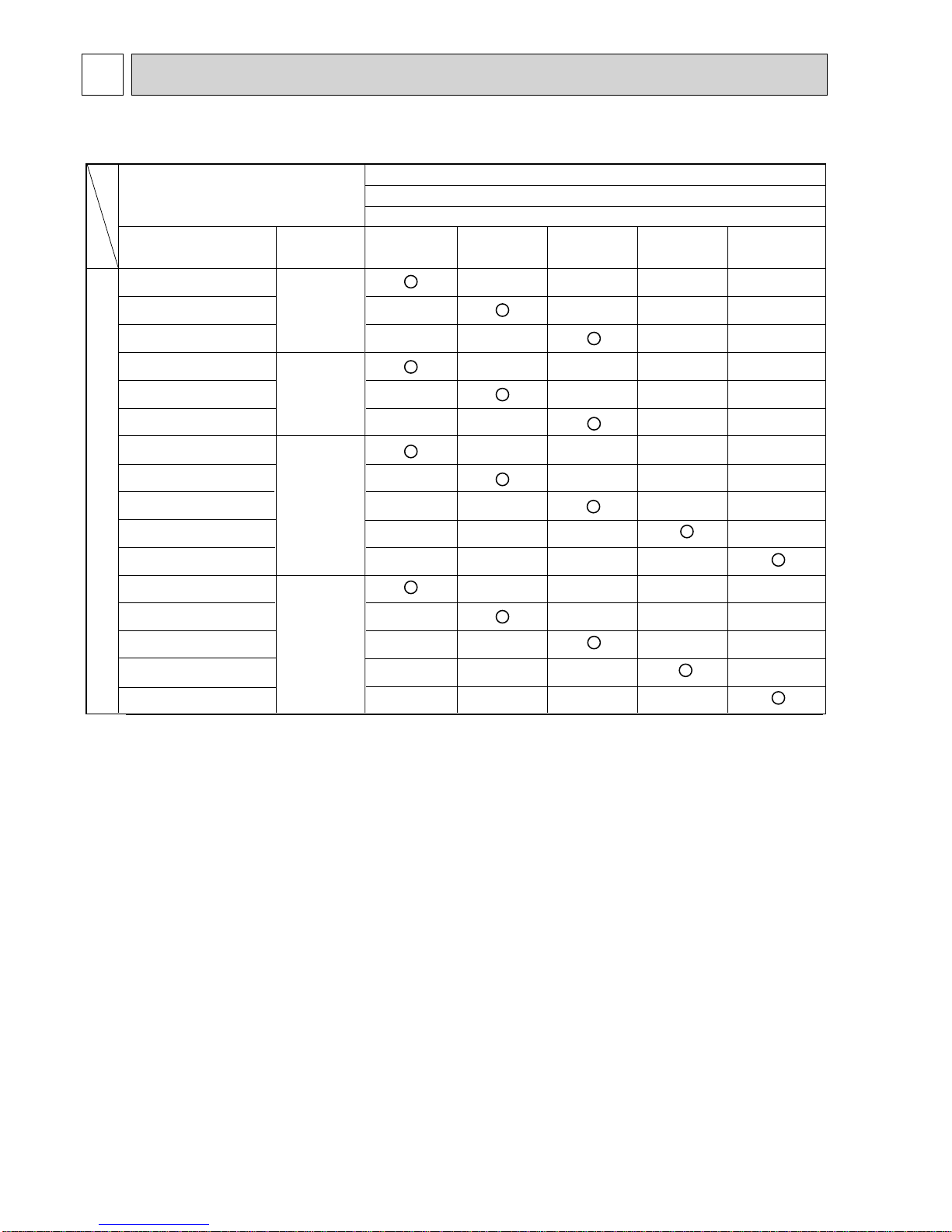
COMBINATION OF INDOOR AND OUTDOOR UNITS
Heat pump type
Outdoor unit
SUZ-
SLZ-KA25VAL2.TH
SLZ-KA35VALR3.TH
SLZ-KA50VALR3.TH
SLZ-KA25VAQ2.TH
SLZ-KA35VAQR2.TH
SLZ-KA50VAQR2.TH
SEZ-KD25VA(L)R2.TH
SEZ-KD35VA(L)R2.TH
SEZ-KD50VA(L)R2.TH
SEZ-KD60VA(L)R2.TH
SEZ-KD71VA(L)R2.TH
SEZ-KD25VAQR2.TH
SEZ-KD35VAQR2.TH
SEZ-KD50VAQR2.TH
SEZ-KD60VAQR2.TH
SEZ-KD71VAQR2.TH
—
—
—
—
—
—
—
—
—
—
—
—
—
—
—
—
—
—
—
—
—
—
—
—
—
—
—
—
—
—
—
—
—
—
—
—
—
—
—
—
—
—
—
—
—
—
—
—
—
—
—
—
—
—
—
—
—
—
—
—
—
—
—
—
OC320
OCH493
Indoor unit
Service
Manual No.
Service Ref.
Heat pump without electric heater
KA25V A4.TH
KA60VA4.TH KA71A4.THKA50VA4.TH
HWE0711
BWE102050
BWE102040
HWE1008
KA35V A4.TH
Note: Please refer to the service manual of indoor unit or the technical data book for the combination data.
INDOOR UNIT SERVICE MANUAL
OCH545
3
2
TECHNICAL CHANGES
Refrigerant
oil
Refrigerant
New refrigerant
R410A
HFC-32: HFC-125 (50%:50%)
Pseudo-azeotropic refrigerant
Not included
A1/A1
72.6
-51.4
1.557
64
Non combustible
0
1730
From liquid phase in cylinder
Possible
Incompatible oil
None
None
Previous refrigerant
R22
R22 (100%)
Single refrigerant
Included
A1
86.5
-40.8
0.94
44.4
Non combustible
0.055
1700
Gas phase
Possible
Compatible oil
Light yellow
None
Refrigerant
Composition (Ratio)
Refrigerant handling
Chlorine
Safety group (ASHRAE)
Molecular weight
Boiling point (°C)
Steam pressure [25°C](Mpa)
Saturated steam density [25°C](Kg/*)
Combustibility
ODP *1
GWP *2
Refrigerant charge method
Additional charge on leakage
Kind
Color
Smell
*1: Ozone Depletion Potential : based on CFC-11
*2: Global Warming Potential : based on CO
2
INFORMATION FOR THE AIR CONDITIONER WITH R410A REFRIGERANT
• This room air conditioner adopts an HFC refrigerant (R410A) which never destroys the ozone layer.
• Pay particular attention to the following points, though the basic installation procedure is same as that for R22 conditioners.
As R410A has working pressure approximate 1.6 times as high as that of R22, some special tools and piping parts/materi-
als are required. Refer to the table below.
Take sufficient care not to allow water and other contaminations to enter the R410A refrigerant during storage and installa-
tion, since it is more susceptible to contaminations than R22.
For refrigerant piping, use clean, pressure-proof parts/materials specifically designed for R410A. (Refer to 2. Refrigerant
piping.)
Composition change may occur in R410A since it is a mixed refrigerant. When charging, charge liquid refrigerant to prevent
composition change.
NOTE : The unit of pressure has been changed to MPa on the international system of units (SI unit system).
The conversion factor is: 1 (MPa [Gauge]) =10.2 (kgf/cm
2
[Gauge])
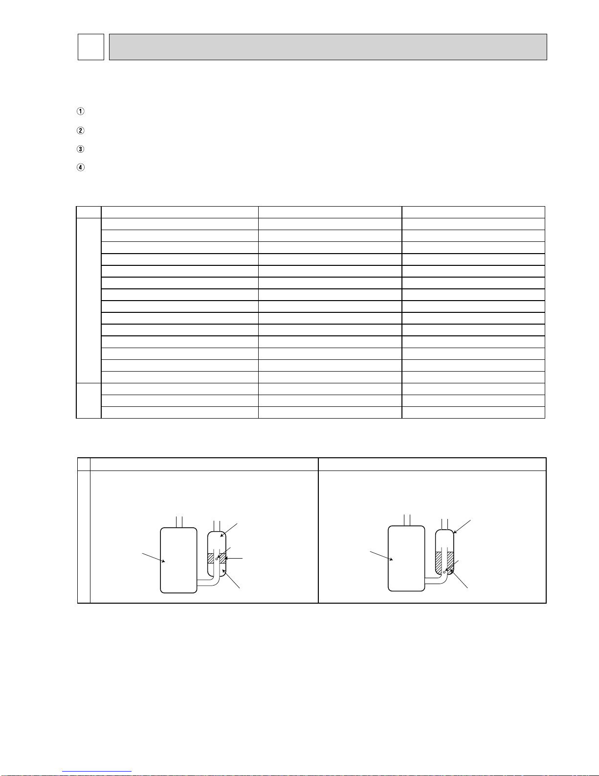
New Specification Current Specification
The incompatible refrigerant oil easily separates from
refrigerant and is in the upper layer inside the suction muffler.
Raising position of the oil back hole enables to back the
refrigerant oil of the upper layer to flow back to the
compressor.
Since refrigerant and refrigerant oil are compatible with
each other, refrigerant oil backs to the compressor through
the lower position oil back hole.
Compressor
Suction muffler
Oil back hole
Refrigerant oil
Refrigerant
Compressor
Suction muffler
Oil back hole
Refrigerant oil /Refrigerant
Compressor
OCH545
4
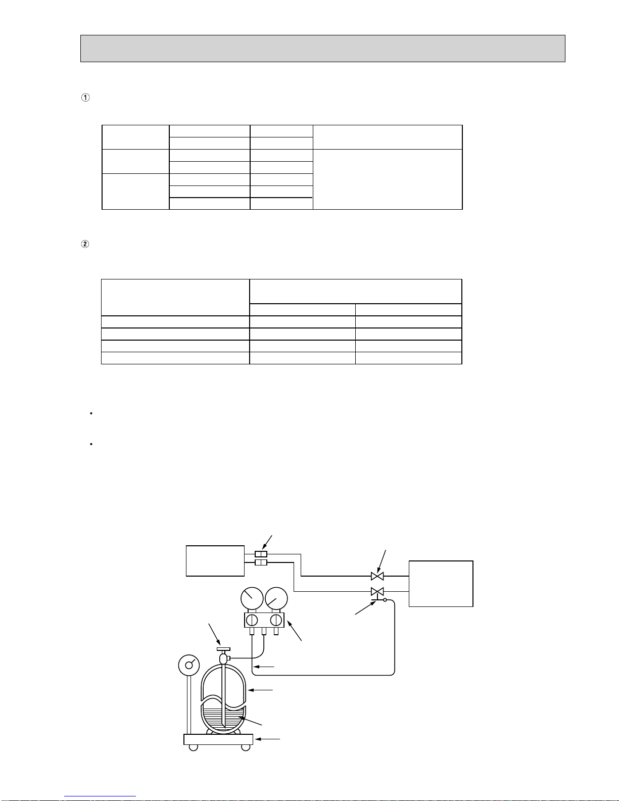
R410A tools Can R22 tools be used?
Gas leak detector
R410A has high pressures beyond the measurement range of existing
gauges. Port diameters have been changed to prevent any other refrigerant
from being charged into the unit.
Hose material and cap size have been changed to improve the pressure
resistance.
Dedicated for HFC refrigerant.
6.35 mm and 9.52 mm
Description
Clamp bar hole has been enlarged to reinforce the spring strength in the tool.
Provided for flaring work (to be used with R22 flare tool).
Provided to prevent the back flow of oil. This adapter enables you to use
vacuum pumps.
It is difficult to measure R410A with a charging cylinder because the
refrigerant bubbles due to high pressure and high-speed vaporization
No
No
No
Yes
Yes
New
New
New
Gauge manifold
Charge hose
Torque wrench
Flare tool
Flare gauge
Vacuum pump
adapter
Electronic scale for
refrigerant charging
No: Not substitutable for R410A Yes: Substitutable for R410A
No 12.7 mm and 15.88 mm
1. Tools dedicated for the air conditioner with R410A refrigerant
The following tools are required for R410A refrigerant. Some R22 tools can be substituted for R410A tools.
The diameter of the service port on the stop valve in outdoor unit has been changed to prevent any other refrigerant being
charged into the unit. Cap size has been changed from 7/16 UNF with 20 threads to 1/2 UNF with 20 threads.
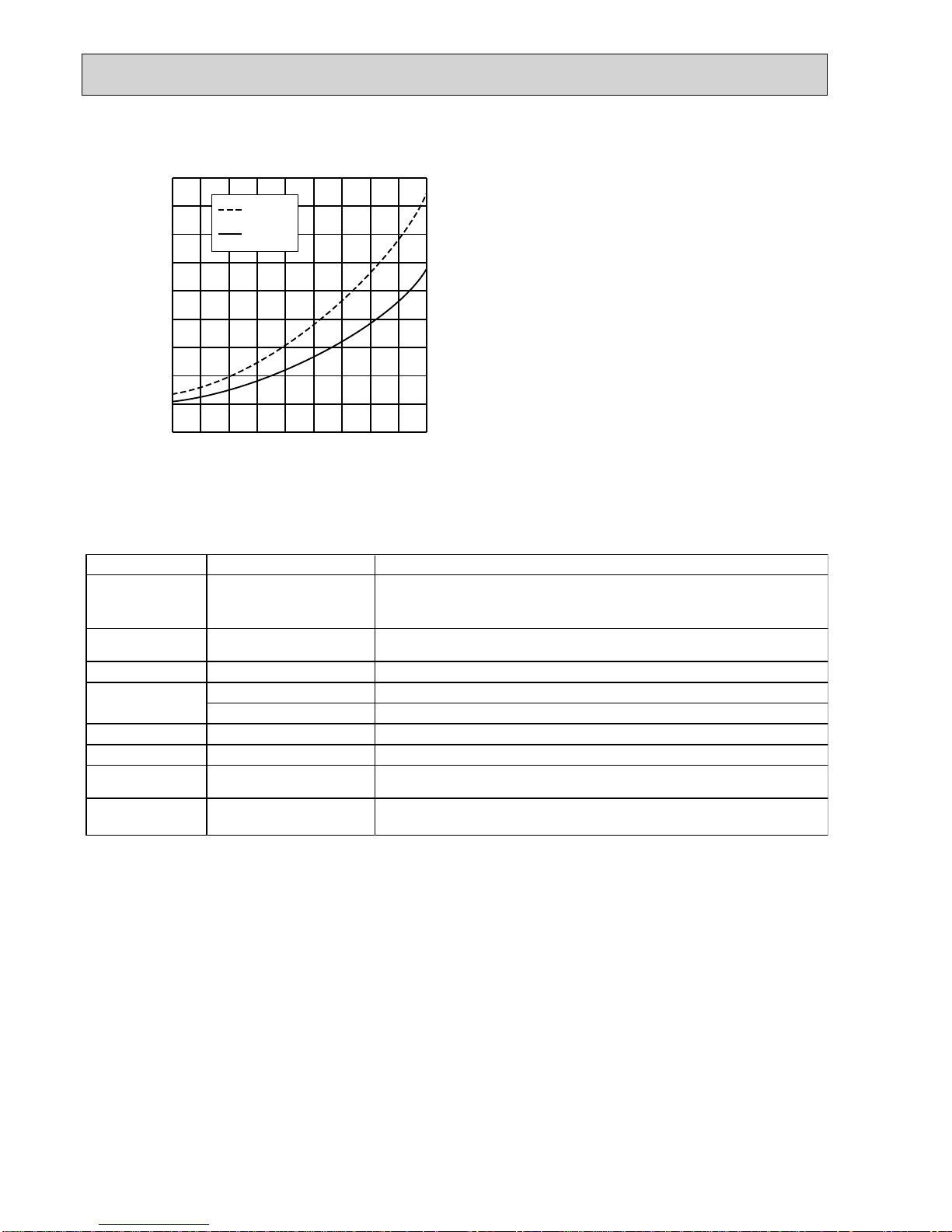
-30 -20 -10 0 10 20
30
40 50 60
-0.5
0.0
0.5
1.0
1.5
2.0
2.5
3.0
3.5
4.0
(MPa [Gauge])
R410A
R22
Conversion chart of refrigerant temperature and pressure
Saturated liquid pressure
()
NOTE: The unit of pressure has been changed to MPa on the
international system of units (SI unit system).
The conversion factor is: 1 (MPa [Gauge]) =10.2 (kgf/cm2 [Gauge])
OCH545
5
Electronic scale for refrigerant charging
Outdoor unit
Refrigerant gas
cylinder
operating valve
Refrigerant gas cylinder
for R410A with siphon
Refrigerant (liquid)
Service port
Gauge manifold
valve (for R410A)
Union
Liquid pipe
Gas pipe
Stop valve
Indoor unit
Charge hose (for R410A)
R410A
Pipe diameter (mm)
6.35
9.52
12.7
15.88
17
22
26
29
Dimension of flare nut (mm)
R22
17
22
24
27
• Use a copper pipe or a copper-alloy seamless pipe with a thickness of 0.8 mm. Never use any pipe with a thickness less
than 0.8mm, as the pressure resistance is insufficient.
Flaring work and flare nut
Flaring work for R410A pipe differs from that for R22 pipe.
For details of flaring work, refer to Installation manual “FLARING WORK”.
3. Refrigerant oil
Apply the special refrigerant oil (accessories: packed with indoor unit) to the flare and the union seat surfaces.
4. Air purge
Do not discharge the refrigerant into the atmosphere.
Take care not to discharge refrigerant into the atmosphere during installation, reinstallation, or repairs to the refrigerant
circuit.
Use the vacuum pump for air purging for the purpose of environmental protection.
5. Additional charge
For additional charging, charge the refrigerant from liquid phase of the gas cylinder.
If the refrigerant is charged from the gas phase, composition change may occur in the refrigerant inside the cylinder and
the outdoor unit. In this case, ability of the refrigerating cycle decreases or normal operation can be impossible. However,
charging the liquid refrigerant all at once may cause the compressor to be locked. Thus, charge the refrigerant slowly.
2. Refrigerant piping
Specifications
Use the refrigerant pipes that meet the following specifications.
Wall thicknessOutside diameter
Pipe
mm mm
For liquid
For gas
6.35
9.52
9.52
12.7
15.88
0.8
0.8
0.8
0.8
1.0
Heat resisting foam plastic
Specific gravity 0.045
Thickness 8 mm
Insulation material
OCH545

6
6. Pumping Down
When relocating or disposing of the air conditioner, pump down the system by following the procedure below so that no
refrigerant is released into the atmosphere.
1 Turn off the power supply (circuit breaker).
2 Connect the gauge manifold valve to the service port of the stop valve on the gas pipe side of the outdoor unit.
3 Fully close the stop valve on the liquid pipe side of the outdoor unit.
4 Supply power (circuit breaker).
5 Perform the refrigerant collecting operation (cooling test run).
• For the PAR-31MAA, select “Service” “TestRun” from the main menu to start the test run, and then select the cooling
mode.
• For details or for other information about starting the test run when using remote controllers, refer to the installation manual
for the indoor unit or the remote controller.
6 Fully close the stop valve on the gas pipe side of the outdoor unit when the pressure gauge shows 0.05 to 0 MPa [Gauge]
(approx. 0.5 to 0 kgf/cm²) and quickly stop the air conditioner.
• Push the “ON/OFF” button on the remote controller to stop the air conditioner.
Note:
When the extension piping is very long with a large refrigerant amount, it may not be possible to perform a pump down
operation. In this case, use refrigerant recovery equipment to collect all of the refrigerant in the system.
7 Turn off the power supply (circuit breaker), remove the gauge manifold valve, and then disconnect the refrigerant pipes.
.Warning: When pumping down the refrigerant, stop the compressor before disconnecting the refrigerant pipes.
• If the refrigerant pipes are disconnected while the compressor is operating and the stop valve (ball valve) is open,
the pressure in the refrigeration cycle could become extremely high if air is drawn in, causing the pipes to burst,
personal injury, etc.
OCH545
77
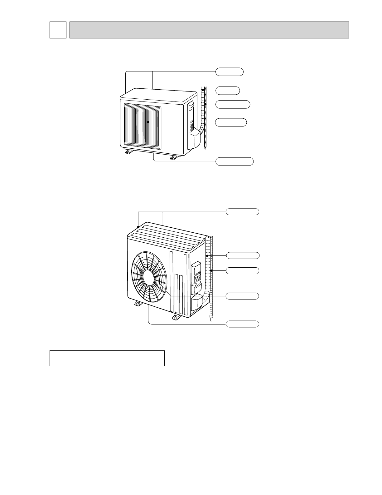
3
PARTS NAMES AND FUNCTIONS
SUZ-KA25VA4.TH
SUZ-KA35VA4.TH
SUZ-KA50VA4.TH
SUZ-KA60VA4.TH
SUZ-KA71VA4.TH
Air outlet
Drain outlet
Piping
Drain hose
Air inlet
(back and side)
Model SUZ-KA·VA4.TH
Drain socket 1
Piping
Air outlet
Drain outlet
Air inlet
(back and side)
Drain hose
OCH545
8
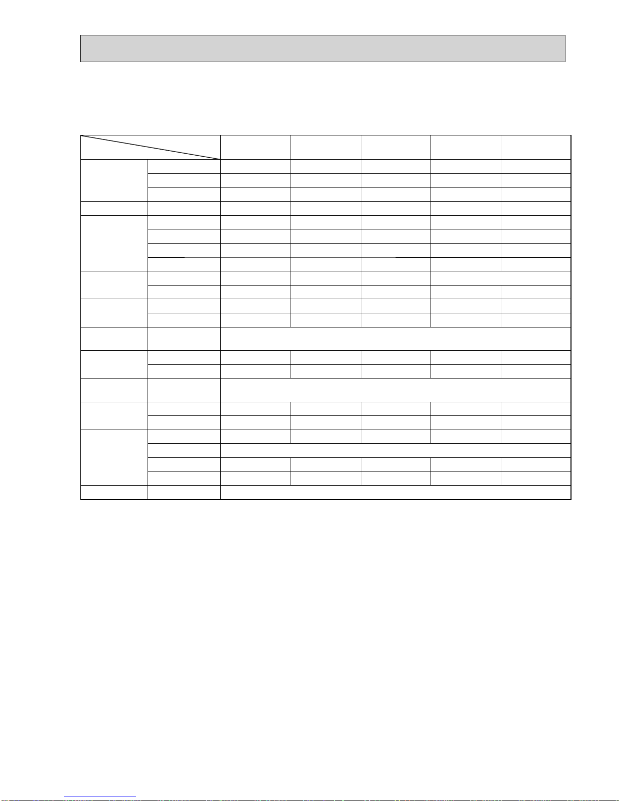
SPECIFICATION
4
NOTE: Test conditions are based on ISO 5151
Cooling : Indoor D.B. 27°C W.B. 19°C
Outdoor D.B. 35°C
Heating : Indoor D.B. 20°C
Outdoor D.B. 7°C W.B. 6°C
Refrigerant piping length (one way): 5 m
*Measured under rated operating frequency.
Outdoor model
SUZ-KA25VA4.TH SUZ-KA35VA4.TH SUZ-KA50VA4.TH SUZ-KA60VA4.TH SUZ-KA71VA4.TH
Power supply Single phase 230V, 50Hz
Compressor
Model KNB073FKFMC KNB092FFAMC SNB130FGBMT SNB172FEKMT
Output W 550 650 900 1,200
Current*
Cooling
A
2.76 4.06 5.58 6.62 8.02
Heating 3.24 4.09 5.75 6.37 8.13
Refrigeration oil
(Model)
L 0.31 (FV50S) 0.27 (FV50S) 0.35 (FV50S) 0.4 (FV50S)
Fan motor
Model RC0J50-FA RC0J60-BD RC0J60-BC
Current*
Cooling
A
0.24 0.29 0.84 0.84 0.83
Heating 0.27 0.28 0.93 0.93 0.82
Dimensions W × H × D mm 800 × 550 × 285 840 × 880 × 330
Weight kg 30 35 54 50 53
Special remarks
Air
fl ow*
Cooling
High
m³/h
1,806 2,868 3,492 3,426
Med. 1,806 2,868 3,066 3,006
Low 1,170 1,038 1,602 1,692 1,512
Heating
High 2,106 2,778 2,952 2,892
Med. 1,806 1,770 2,778 2,952 2,892
Low 1,452 1,326 2,124 2,226 2,280
Sound level*
Cooling
dB(A)
47 49 52 55
Heating 48 50 52 55
Fan
speed
Cooling
High
rpm
740 810 840 950
Med. 740 810 840
Low 740 490 480 450
Heating
High 860 900 810
Med. 740 770 810
Low 600 610 620 650
Fan speed regulator 3
Refrigerant fi lling capacity
(R410A)
kg 0.80 1.15 1.60 1.80 1.80
OCH545
99
SUZ-KA25VA4.TH SUZ-KA35VA4.TH
SUZ-KA50VA4.TH SUZ-KA60VA4.TH
SUZ-KA71VA4.TH
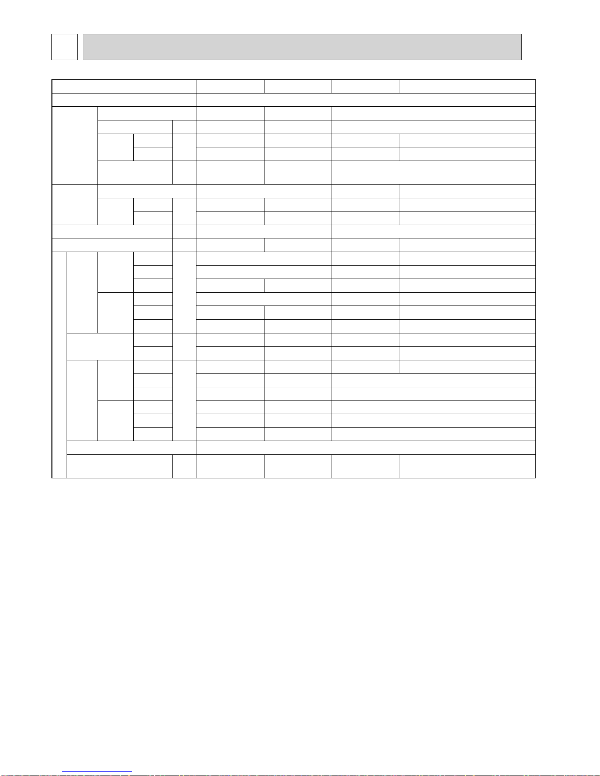
Specifications and rating conditions of main electric parts
Model
Item
SUZ-KA25VA4.TH SUZKA35VA4.TH SUZ-KA50VA4.TH SUZ-KA60VA4.TH SUZ-KA71VA4.TH
Smoothing
capacitor
(C61) — — 620F 420V — —
(C62, C63) 620F 420V 620F 420V 620F420V — —
(CB1, 2, 3) — — — 560F 450V 560F 350V
Diode module (DB61) 15A 600V 15A 600V 25A 600V — —
Fuse
(F61) T20A L250V T20A L250V T20A L250V — —
(F62) — — — T20A L250V T20A L250V
(F701, F801, F901)
T3.15A L250V T3.15A L250V T3.15A L250V — —
(IC700) 15A 600V 15A 600V 20A 600V — —
Inteligent power
module
(IPM) — — — 20A 600V
(IC932) 8A 600V 8A 600V 8A 600V 5A 600V 5A 600V
Power factor
controller
(PFC) — — — 20A 600V 20A 600V
(IC820) 20A 600V 20A 600V 20A 600V — —
Expansion valve
coil
(LEV) DC12V
Reactor
(L61) 18mH 23mH 23mH — —
(L) — — — 340H 20A 340H 20A
Current-Limiting
PTC thermistoe
(PTC64, PTC65) 33
Terminal block
(TB1, TB2) — — — 3P 3P
(TB) 5P 5P 5P — —
Relay
(X63) 3A 250V 3A 250V 3A 250V — —
(X64) 20A 250V
(X601) — — — 3A 250V 3A 250V
(X602) — — — 3A 250V 3A 250V
R.V. coil (21S4) AC220-240V
OCH545
10
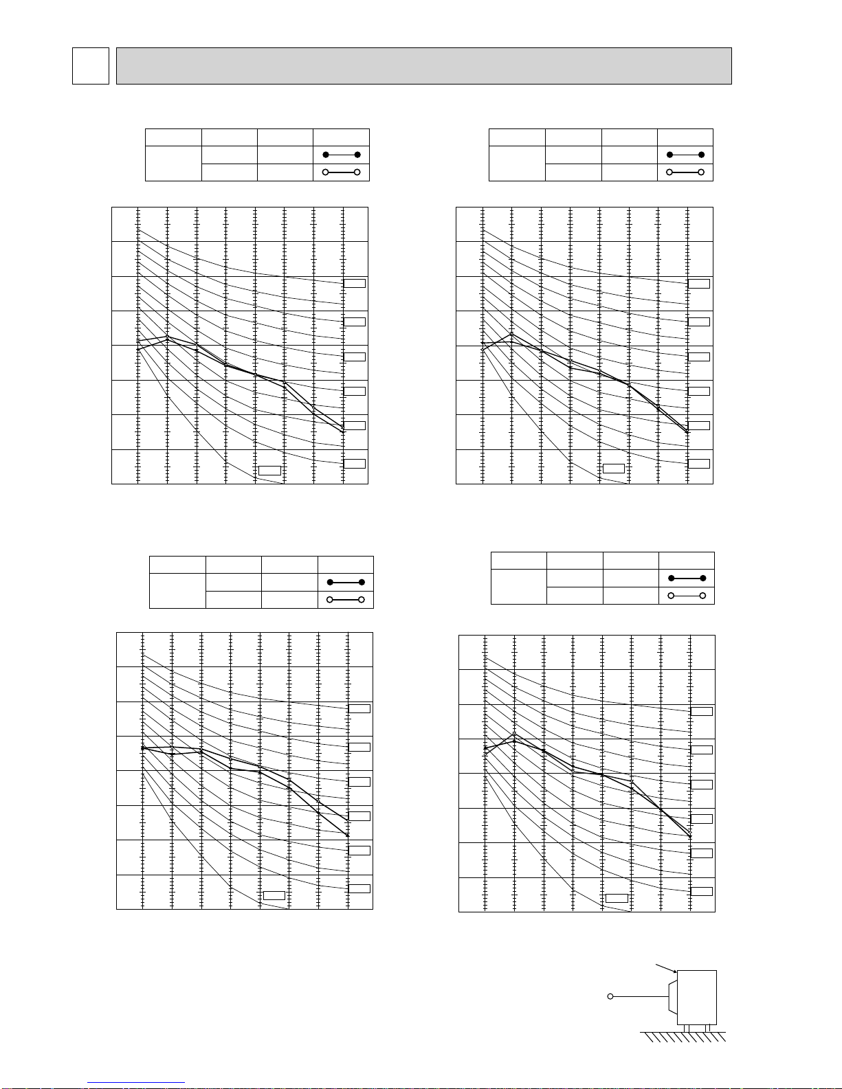
NOISE CRITERIA CURVES
5
OCTAVE BAND SOUND PRESSURE LEVEL, dB re 0.0002 MICRO BAR
COOLING
FUNCTION
SPL(dB(A))
LINE
High
Med.
FAN SPEED
HEATING
47
48
90
80
70
60
50
40
30
20
10
63 125 250 500 1000 2000 4000 8000
NC-60
NC-50
NC-40
NC-30
NC-20
NC-70
BAND CENTER FREQUENCIES, Hz
NC-10
SUZ-KA25VA4.TH
OCTAVE BAND SOUND PRESSURE LEVEL, dB re 0.0002 MICRO BAR
COOLING
FUNCTION
SPL(dB(A))
LINE
FAN SPEED
HEATING
49
50
High
Med.
90
80
70
60
50
40
30
20
10
63 125 250 500 1000 2000 4000 8000
NC-60
NC-50
NC-40
NC-30
NC-20
NC-70
BAND CENTER FREQUENCIES, Hz
NC-10
SUZ-KA35VA4.TH
COOLING
FUNCTION
SPL(dB(A)) LINE
High
FAN SPEED
HEATING
52
52
OCTAVE BAND SOUND PRESSURE LEVEL, dB re 0.0002 MICRO BAR
90
80
70
60
50
40
30
20
10
63 125 250 500 1000 2000 4000 8000
NC-60
NC-50
NC-40
NC-30
NC-20
NC-70
BAND CENTER FREQUENCIES, Hz
NC-10
SUZ-KA50VA4.TH
Test conditions
Cooling: Dry-bulb temperature 35°C
Heating: Dry-bulb temperature 7°C
Wet-bulb temperature 6°C
OUTDOOR UNIT
MICROPHONE
1 m
SUZ-KA60VA4.TH SUZ-KA71VA4.TH
OCTAVE BAND SOUND PRESSURE LEVEL, 0dB re 0.0002 MICRO BAR
COOLING
FUNCTION
SPL(dB(A)) LINE
High
FAN SPEED
HEATING
55
55
90
80
70
60
50
40
30
20
10
63 125 250 500 1000 2000 4000 8000
NC-60
NC-50
NC-40
NC-30
NC-20
NC-70
BAND CENTER FREQUENCIES, Hz
NC-10
OCH545

11
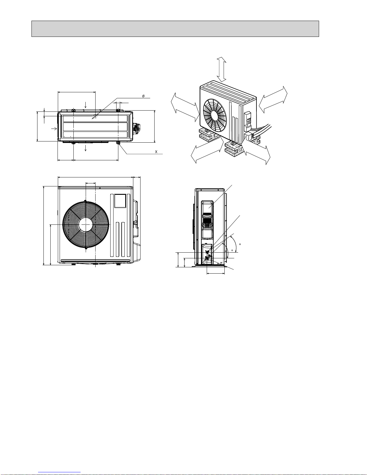
6
OUTLINES AND DIMENSIONS
10
69
800
302.5
500 Bolt pitch for installation
150
22.3
Handle
550
280
164.5
99.5
170.5
23
Service panel
Service port
285
344.5
44
400
Air in
Air out
Air in
17.5
Bolt pitch for
installation
304~325
40
Liquid refrigerant pipe joint
Refrigerant pipe (flared) :6.35
Gas refrigerant pipe joint
Refrigerant pipe (flared) :9.52
43
35
2-Oval holes 10×21
REQUIRED SPACE
Basically open 100mm or more
without any obstruction in front
and on both sides of the unit.
350mm or more
200mm or more
100mm or more
100mm or more
Open two sides of left,
right, or rear side.
Drain hole :42
Unit: mm
SUZ-KA25VA4.TH
SUZ-KA35VA4.TH
OCH545
12
417.5
40
42
Drain hole
175
500
330
50
Air in
Air out
2-Oval holes 10 21
840
109
81
880
452
Service panel
99.5
164.5
195
35
44
Liquid refrigerant
pipe joint
Refrigerant pipe
(flared)
Ø 6.35...(SUZ-KA50/60VA4)
Ø 9.52...(SUZ-KA71VA4)
Gas refrigerant
pipe joint
Refrigerant pipe
(flared)
Ø 12.7...(SUZ-KA50VA4)
Ø 15.88...(SUZ-KA60/71VA4)
350 mm or more
100 mm or more
REQUIRED SPACE
Open as a rule
500mm or more if
the front and both
sides are open
100mm or more
200mm or more if
there are obstacles
to both sides
Open as a rule
500mm or more if the back,
both sides and top are open
Air in
Bolt pitch for
installation
360
SUZ-KA50VA4.TH
SUZ-KA60VA4.TH
SUZ-KA71VA4.TH
Unit: mm
OCH545
1313
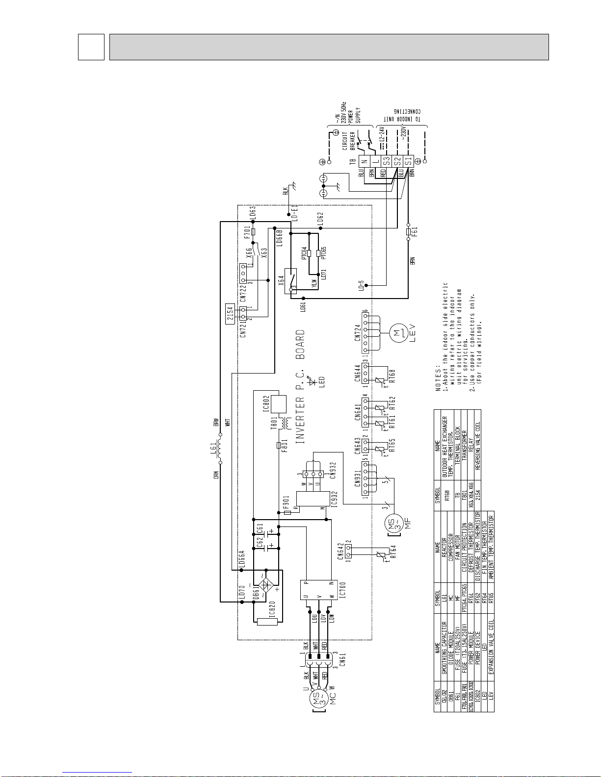
7
WIRING DIAGRAM
SUZ-KA25VA4.TH
SUZ-KA35VA4.TH
OCH545
14
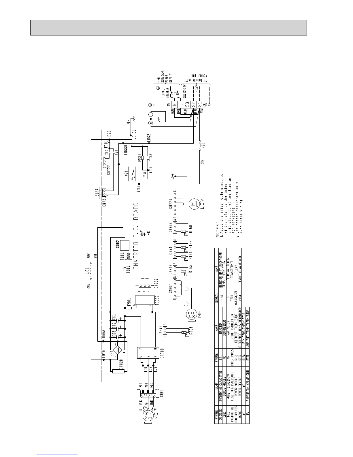
SUZ-KA50VA4.TH
OCH545
 Loading...