

Mitsubishi Electric SUZ-KA25VA5, SUZ-KA60VA5, SUZ-KA50VA5, SUZ-KA35VA5, SUZ-KA71VA5 Service Manual
Page 1
TECHNICAL & SERVICE MANUAL
R410A
CONTENTS
1.
COMBINATION OF INDOOR AND OUTDOOR UNITS
.....
2
2. PARTS NAMES AND FUNCTIONS
..................
3
3. SPECIFICATION
................................................
4
4. NOISE CRITERIA CURVES
..............................
6
5. OUTLINES AND DIMENSIONS
........................
7
6. WIRING DIAGRAM
............................................
9
7. REFRIGERANT SYSTEM DIAGRAM
.............
12
8. ACTUA TOR CONTROL
...................................
16
9. SERVICE FUNCTIONS
...................................
17
10. TROUBLESHOOTING
.....................................
17
11. DISASSEMBLY PROCEDURE
........................
34
Indication of
model name
Note:
•
This service manual describes
service data of the outdoor
units only.
HFC
utilized
R410A
SUZ-KA25VA5.TH
SUZ-KA35VA5.TH
PARTS CATALOG (OCB603)
No. OCH603
October 2015
SPLIT-TYPE, HEAT PUMP AIR CONDITIONERS
[Model Name]
SUZ-KA25VA5
SUZ-KA35VA5
SUZ-KA50VA5
SUZ-KA60VA5
SUZ-KA71VA5
[Service Ref.]
SUZ-KA25VA5.TH
SUZ-KA25VA5.TH-ET
SUZ-KA35VA5.TH
SUZ-KA35VA5.TH-ET
SUZ-KA50VA5.TH
SUZ-KA50VA5.TH-ET
SUZ-KA60VA5.TH
SUZ-KA60VA5.TH-ET
SUZ-KA71VA5.TH
SUZ-KA71VA5.TH-ET
Page 2
2
1
COMBINATION OF INDOOR AND OUTDOOR UNITS
INDOOR UNIT SERVICE MANUAL
Indoor unit
Outdoor unit
Heat pump type
SUZ-
Service Ref.
Service
manual No.
KA25VA5.TH
KA25VA5.TH-ET
KA35VA5.TH
KA35VA5.TH-ET
KA50VA5.TH
KA50VA5.TH-ET
KA60VA5.TH
KA60VA5.TH-ET
KA71VA5.TH
KA71VA5.TH-ET
Heat pump without electric heater
SLZ-KF25VA.TH
OCH600
OCB600
─ ─ ─ ─
SLZ-KF35VA.TH ─ ─ ─ ─
SLZ-KF50VA.TH ─ ─ ─ ─
SLZ-KF60VA.TH ─ ─ ─ ─
SEZ-KD25VAQR2.TH
HWE1008
BWE102040
(BWE014090)
─ ─ ─ ─
SEZ-KD35VAQR2.TH ─ ─ ─ ─
SEZ-KD50VAQR2.TH ─ ─ ─ ─
SEZ-KD60VAQR2.TH ─ ─ ─ ─
SEZ-KD71VAQR2.TH ─ ─ ─ ─
SEZ-KD25VALR2.TH
HWE0711
BWE012050
─ ─ ─ ─
SEZ-KD35VALR2.TH ─ ─ ─ ─
SEZ-KD50VALR2.TH ─ ─ ─ ─
SEZ-KD60VALR2.TH ─ ─ ─ ─
SEZ-KD71VALR2.TH ─ ─ ─ ─
PLA-RP35BAR4.UK
OCH412
OCB412
─ ─ ─ ─
PLA-RP50BAR4.UK ─ ─ ─ ─
PLA-RP60BAR4.UK ─ ─ ─ ─
PLA-RP71BAR4.UK ─ ─ ─ ─
PCA-RP35KAQR2
OCH491
OCB491
─ ─ ─ ─
PCA-RP50KAQR2 ─ ─ ─ ─
PCA-RP60KAQR2 ─ ─ ─ ─
PCA-RP71KAQR2 ─ ─ ─ ─
PEAD-RP35JAQR2.UK
BWE014160
─ ─ ─ ─
PEAD-RP50JAQR2.UK ─ ─ ─ ─
PEAD-RP60JAQR2.UK ─ ─ ─ ─
PEAD-RP71JAQR2.UK ─ ─ ─ ─
PEAD-RP35JALR2.UK
BWE09350
─ ─ ─ ─
PEAD-RP50JALR2.UK ─ ─ ─ ─
PEAD-RP60JALR2.UK ─ ─ ─ ─
PEAD-RP71JALR2.UK ─ ─ ─ ─
OCH603
Page 3
3
2
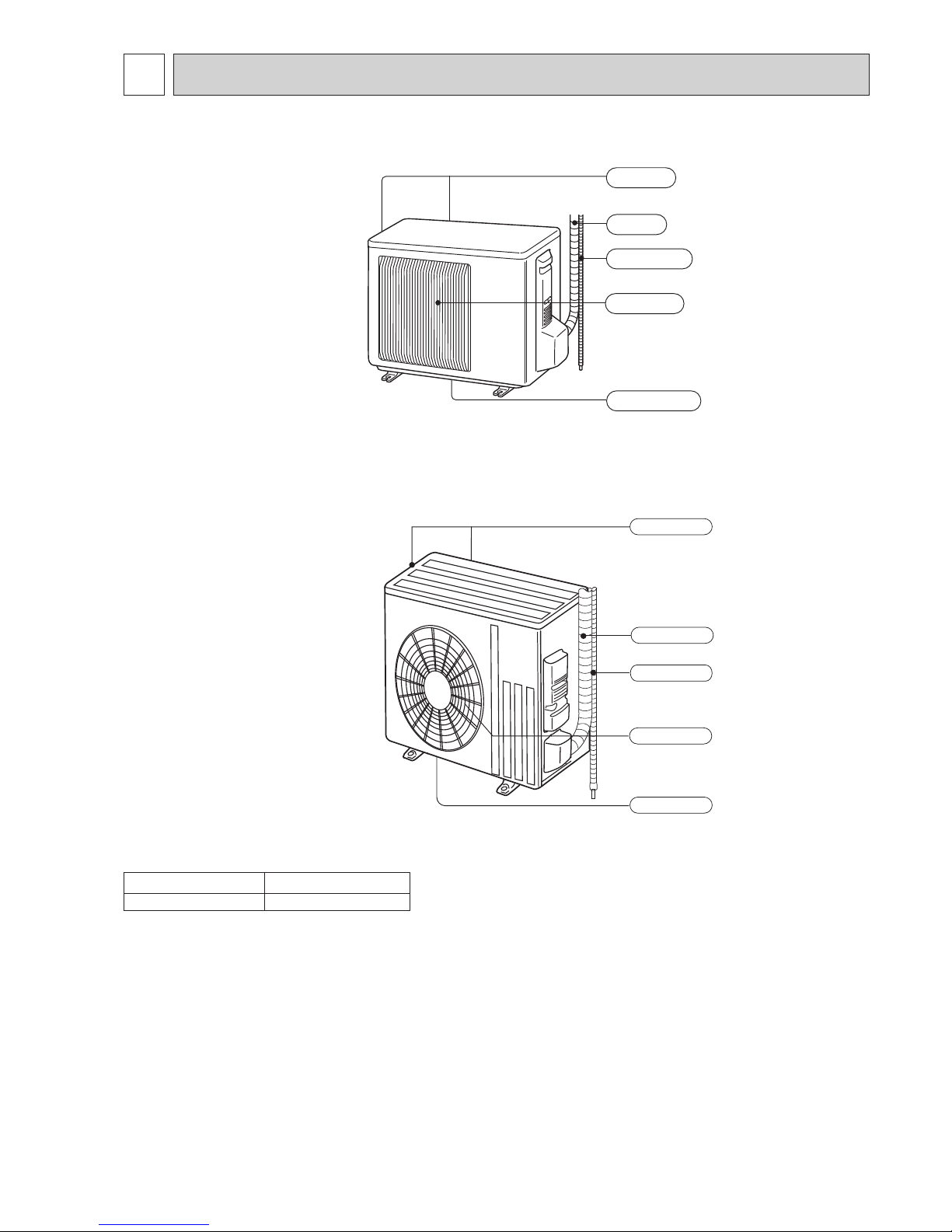
PARTS NAMES AND FUNCTIONS
SUZ-KA25VA5
SUZ-KA35VA5
SUZ-KA50VA5
SUZ-KA60VA5
SUZ-KA71VA5
Air outlet
Drain outlet
Piping
Drain hose
Air inlet
(back and side)
Model SUZ-KA·VA5
Drain socket 1
Piping
Air outlet
Drain outlet
Air inlet
(back and side)
Drain hose
Piping
Air outlet
Drain outlet
Air inlet
(back and side)
Drain hose
OCH603
Page 4
4
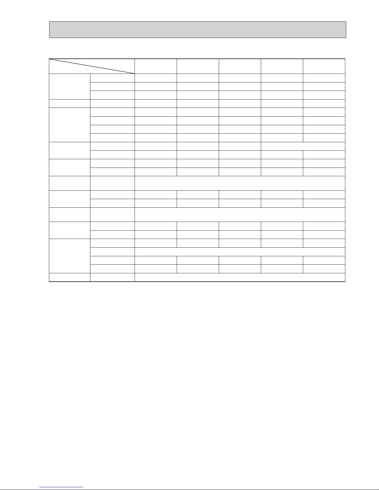
SPECIFICATION
3
Note: Test conditions are based on ISO 5151
Cooling : Indoor D.B. 27°C W.B. 19°C
Outdoor D.B. 35°C
Heating : Indoor D.B. 20°C
Outdoor D.B. 7°C W.B. 6°C
Refrigerant piping length (one way): 5 m
*Measured under rated operating frequency.
Outdoor model
SUZ-KA25VA5.TH
SUZ-KA25VA5.TH-ET
SUZ-KA35VA5.TH
SUZ-KA35VA5.TH-ET
SUZ-KA50VA5.TH
SUZ-KA50VA5.TH-ET
SUZ-KA60VA5.TH
SUZ-KA60VA5.TH-ET
SUZ-KA71VA5.TH
SUZ-KA71VA5.TH-ET
Power supply Single phase 230 V, 50 Hz
Compressor
Model KNB073FKFMC KNB092FFAMC SNB130FGBMT SNB172FEKMT
Output W 550 650 900 1,200
Current*
Cooling
A
2.76 4.06 5.58 6.62 8.02
Heating 3.24 4.09 5.75 6.37 8.13
Refrigeration oil
(Model)
L 0.31 (FV50S) 0.27 (FV50S) 0.35 (FV50S) 0.4 (FV50S)
Fan motor
Model RC0J50-NA RC0J60-BC RC0J60-BC
Current*
Cooling
A
0.24 0.29 0.84 0.84 0.83
Heating 0.27 0.28 0.93 0.93 0.82
Dimensions W × H × D mm 800 × 550 × 285 840 × 880 × 330
Weight kg 30 35 54 50 53
Special remarks
Air
ow*
Cooling
High
m³/h
1,806 2,868 3,492 3,426
Med. 1,806 2,868 3,066 3,006
Low 1,170 1,038 1,602 1,692 1,512
Heating
High 2,106 2,778 2,952 2,892
Med. 1,806 1,770 2,778 2,952 2,892
Low 1,452 1,326 2,124 2,226 2,280
Sound pressure level*
Cooling
dB(A)
47 49 52 55
Heating 48 50 52 55
Sound power level
58 62 65 65 69
Fan
speed
Cooling
High
rpm
740 810 840 950
Med. 740 810 840
Low 740 490 480 450
Heating
High 860 900 810
Med. 740 770 810
Low 600 610 620 650
Fan speed regulator 3
Refrigerant lling capacity
(R410A)
kg 0.80 1.15 1.60 1.60 1.80
OCH603
Page 5
55
Specifications and rating conditions of main electric parts
Model
Item
SUZ-KA25VA5 SUZ-KA35VA5 SUZ-KA50VA5 SUZ-KA60VA5 SUZ-KA71VA5
Smoothing
capacitor
(C61) — — 620 μF 420 V — —
(C62, C63) 620 μF 420 V 620 μF 420 V 620 μF420 V — —
(CB1, 2, 3) — — — 560 μF 450 V 560 μF 350 V
Diode module (DB61) 15 A 600 V 15 A 600 V 25 A 600 V — —
Fuse
(F61) T20 A L250 V T20 A L250 V T20 A L250 V — —
(F62) — — — T20A L250V T20A L250V
(F701, F801, F901)
T3.15 A L250 V T3.15 A L250 V T3.15 A L250 V — —
(IC700) 15 A 600 V 15 A 600 V 20 A 600 V — —
Inteligent power
module
(IPM) — — — 20 A 600 V
(IC932) 8 A 600 V 8 A 600 V 8 A 600 V 5 A 600 V 5 A 600 V
Power factor
controller
(PFC) — — — 20A 600V 20A 600V
(IC820) 20 A 600 V 20 A 600 V 20 A 600 V — —
Expansion valve
coil
(LEV) 12 V DC
Reactor
(L61) 18 mH 23 mH 23 mH — —
(L) — — — 340 μH 20 A 340 μH 20 A
Current-Limiting
PTC thermistor
(PTC64, PTC65) 33Ω
Terminal block
(TB1, TB2) — — — 3P 3P
(TB) 5P 5P 5P — —
Relay
(X63) 3 A 250 V 3 A 250 V 3 A 250 V — —
(X64) 20 A 250 V
(X601) — — — 3 A 250 V 3 A 250 V
(X602) — — — 3 A 250 V 3 A 250 V
R.V. coil (21S4) 220–240 V AC
OCH603
Page 6
6
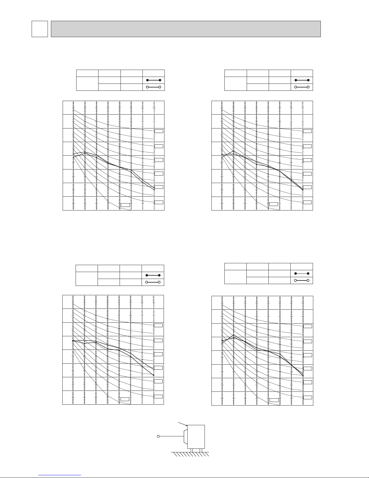
NOISE CRITERIA CURVES
4
OCTAVE BAND SOUND PRESSURE LEVEL, dB re 0.0002 MICRO BAR
COOLING
FUNCTION
SPL(dB(A))
LINE
High
Med.
FAN SPEED
HEATING
47
48
90
80
70
60
50
40
30
20
10
63 125 250 500 1000 2000 4000 8000
NC-60
NC-50
NC-40
NC-30
NC-20
NC-70
BAND CENTER FREQUENCIES, Hz
NC-10
SUZ-KA25VA5.TH
SUZ-KA25VA5.TH-ET
OCTAVE BAND SOUND PRESSURE LEVEL, dB re 0.0002 MICRO BAR
COOLING
FUNCTION
SPL(dB(A))
LINE
FAN SPEED
HEATING
49
50
High
Med.
90
80
70
60
50
40
30
20
10
63 125 250 500 1000 2000 4000 8000
NC-60
NC-50
NC-40
NC-30
NC-20
NC-70
BAND CENTER FREQUENCIES, Hz
NC-10
SUZ-KA35VA5.TH
SUZ-KA35VA5.TH-ET
COOLING
FUNCTION
SPL(dB(A)) LINE
High
FAN SPEED
HEATING
52
52
OCTAVE BAND SOUND PRESSURE LEVEL, dB re 0.0002 MICRO BAR
90
80
70
60
50
40
30
20
10
63 125 250 500 1000 2000 4000 8000
NC-60
NC-50
NC-40
NC-30
NC-20
NC-70
BAND CENTER FREQUENCIES, Hz
NC-10
SUZ-KA50VA5.TH
SUZ-KA50VA5.TH-ET
Test conditions
Cooling: Dry-bulb temperature 35°C
Heating: Dry-bulb temperature 7°C
Wet-bulb temperature 6°C
OUTDOOR UNIT
MICROPHONE
1 m
SUZ-KA60VA5.TH SUZ-KA71VA5.TH
SUZ-KA60VA5.TH-ET SUZ-KA71VA5.TH-ET
OCTAVE BAND SOUND PRESSURE LEVEL, 0dB re 0.0002 MICRO BAR
COOLING
FUNCTION
SPL(dB(A)) LINE
High
FAN SPEED
HEATING
55
55
90
80
70
60
50
40
30
20
10
63 125 250 500 1000 2000 4000 8000
NC-60
NC-50
NC-40
NC-30
NC-20
NC-70
BAND CENTER FREQUENCIES, Hz
NC-10
OCH603
Page 7
7
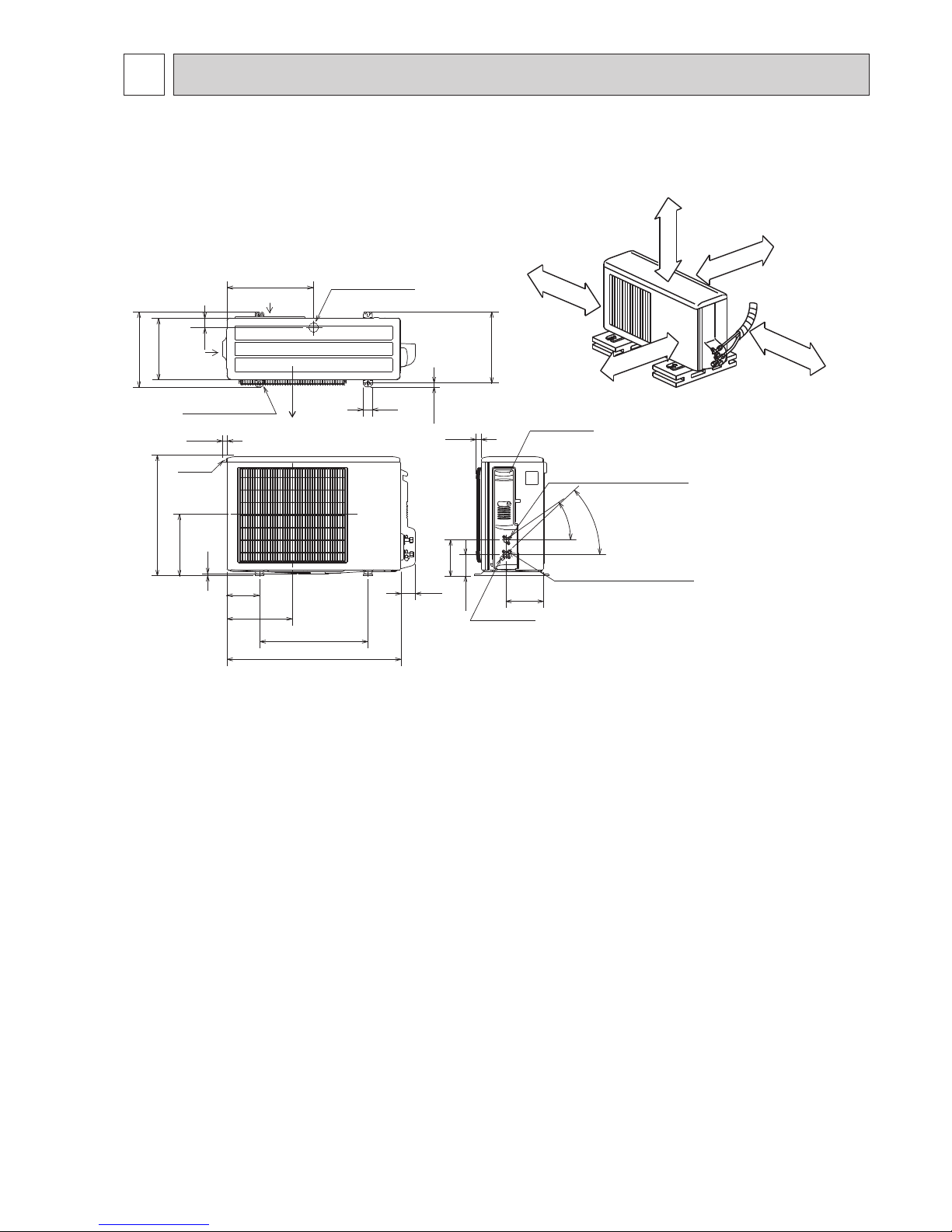
5
OUTLINES AND DIMENSIONS
10
69
800
302.5
500 Bolt pitch for installation
150
22.3
Handle
550
280
164.5
99.5
170.5
23
Service panel
Service port
285
344.5
44
400
Air in
Air out
Air in
17.5
Bolt pitch for
installation
304~325
40
Liquid refrigerant pipe joint
Refrigerant pipe (flared) [6.35
Gas refrigerant pipe joint
Refrigerant pipe (flared) [9.52
43-
35-
2-Oval holes 10×21
REQUIRED SPACE
Basically, leave this space open.
Only if front and both sides are open,
leave 100 mm at minimum.
350mm or more
200mm or more
100mm or more
100mm or more
200 mm or more.
Leave any two sides among
right, left or rear open.
Drain hole [42
Unit: mm
SUZ-KA25V A5.TH SUZ-KA35V A5.TH
SUZ-KA25VA5.TH-ET SUZ-KA35VA5.TH-ET
OCH603
Page 8
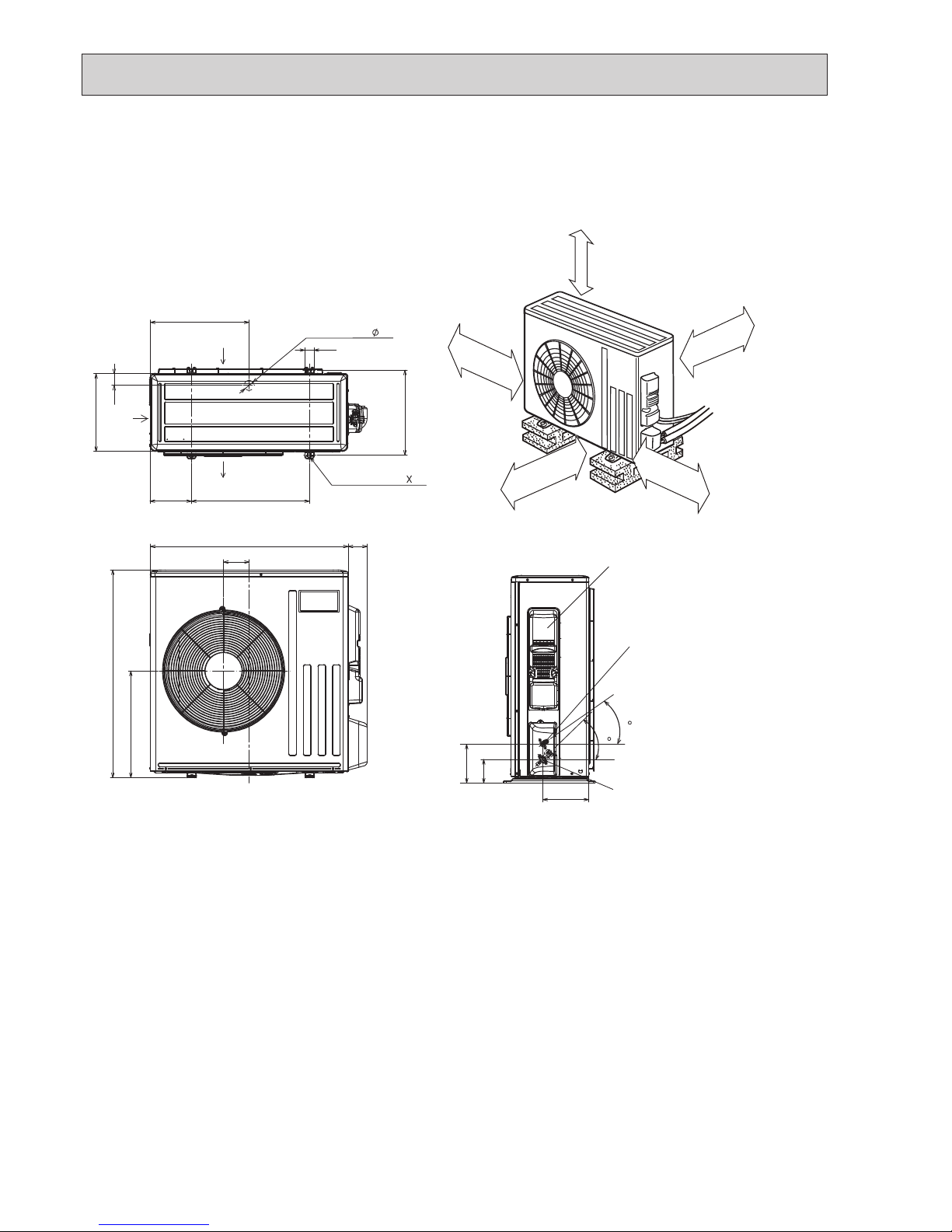
8
417.5
40
42
Drain hole
175
500
330
50
Air in
Air out
2-Oval holes 10 21
840
109
81
880
452
Service panel
99.5
164.5
195
35
44
Liquid refrigerant
pipe joint
Refrigerant pipe
(flared)
Ø 6.35...(SUZ-KA50/60VA5)
Ø 9.52...(SUZ-KA71VA5)
Gas refrigerant
pipe joint
Refrigerant pipe
(flared)
Ø 12.7...(SUZ-KA50VA5)
Ø 15.88...(SUZ-KA60/71VA5)
350 mm or more
100 mm or more
REQUIRED SPACE
Basically, leave this space open.
Only if front and both sides are open,
leave 500 mm at minimum.
100mm or more
500 mm or more.
Leave any two sides among
right, left or rear open.
Air in
Bolt pitch for
installation
360
Unit: mm
SUZ-KA50V A5.TH SUZ-KA60V A5.TH SUZ-KA71VA5.TH
SUZ-KA50VA5.TH-ET SUZ-KA60VA5.TH-ET SUZ-KA71VA5.TH-ET
OCH603
Page 9
99
6
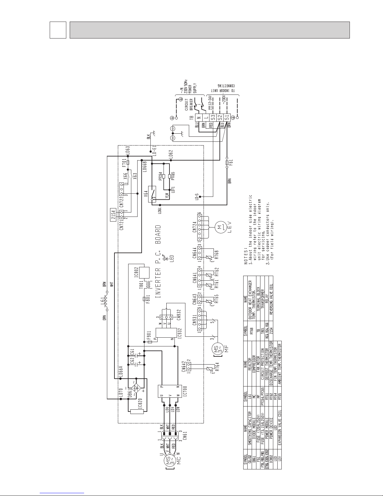
WIRING DIAGRAM
SUZ-KA25V A5.TH SUZ-KA35V A5.TH
SUZ-KA25VA5.TH-ET SUZ-KA35VA5.TH-ET
OCH603
Page 10
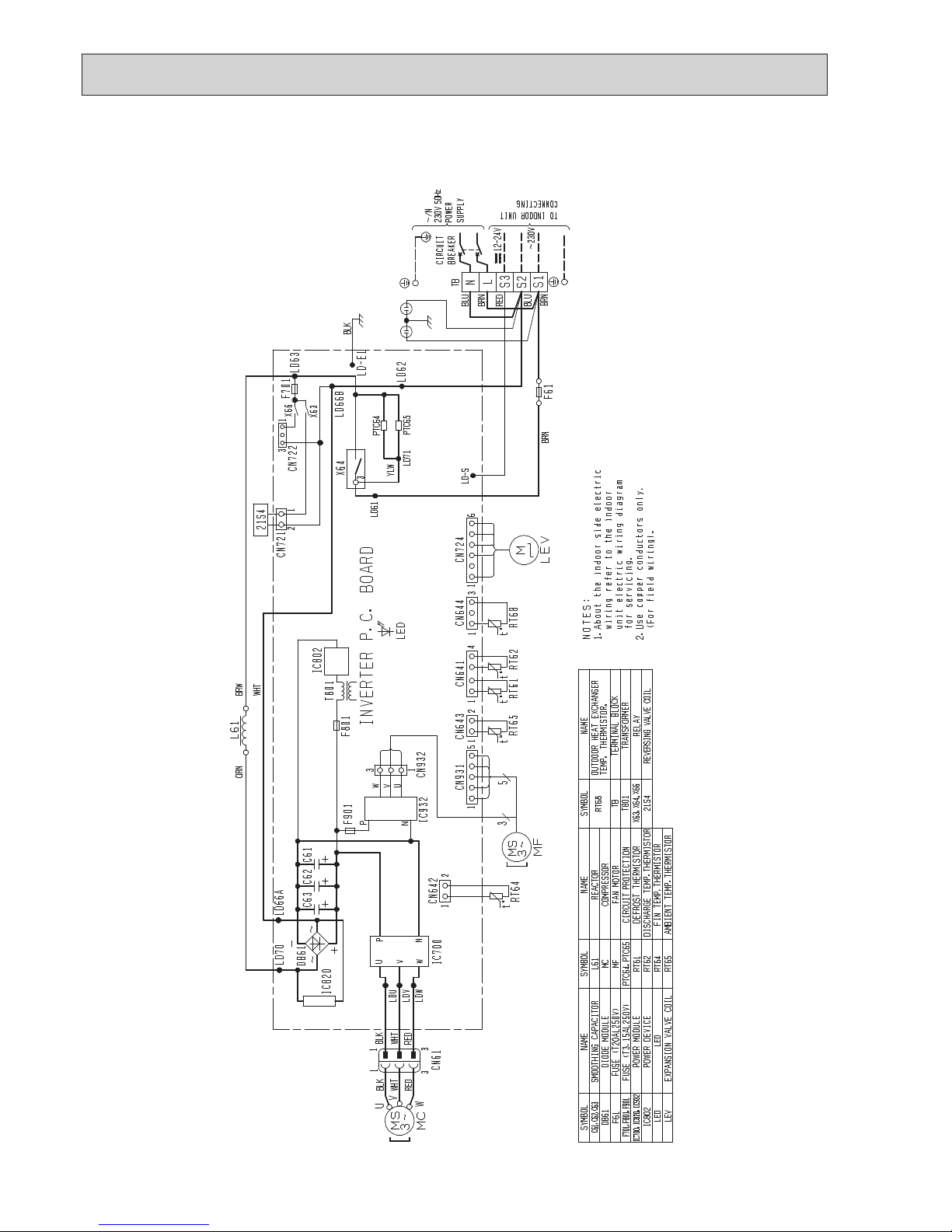
10
SUZ-KA50VA5.TH
SUZ-KA50VA5.TH-ET
OCH603
Page 11
11
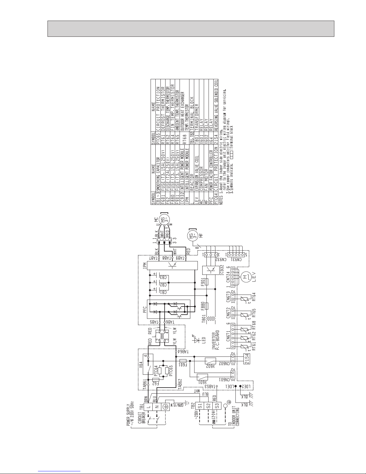
SUZ-KA60VA5.TH SUZ-KA71VA5.TH
SUZ-KA60VA5.TH-ET SUZ-KA71VA5.TH-ET
OCH603
Page 12
12
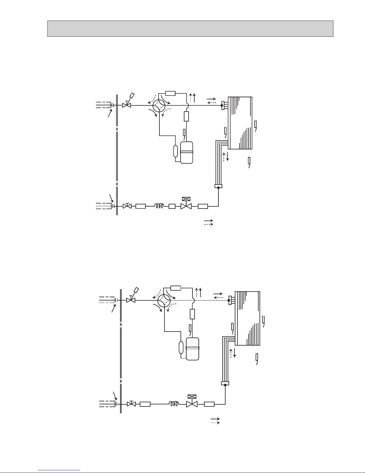
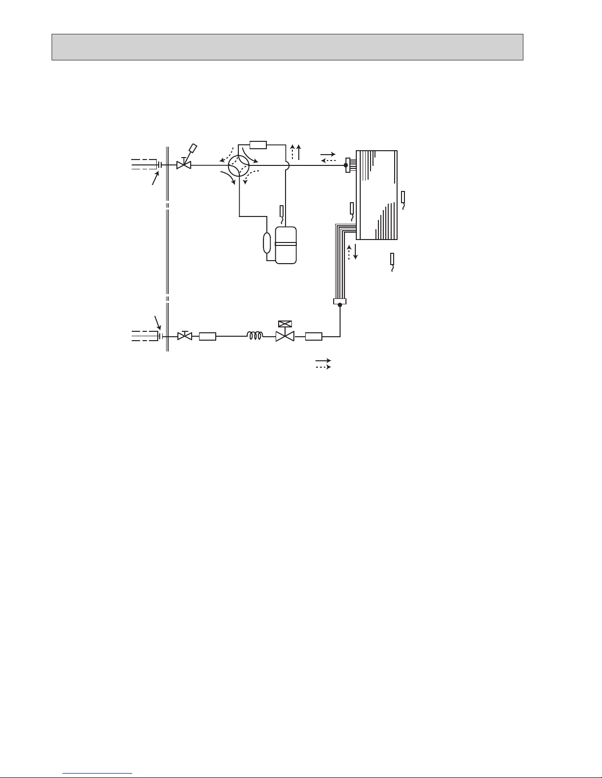
REFRIGERANT SYSTEM DIAGRAM
7
Unit: mm
SUZ-KA25VA5.TH
SUZ-KA25VA5.TH-ET
Unit: mm
SUZ-KA35VA5.TH
SUZ-KA35VA5.TH-ET
Flared connection
Defrost
thermistor
RT61
Discharge
temperature
thermistor
RT62
Flared connection
Stop valve
(with strainer)
Stop valve
(with service port)
Refrigerant flow in cooling
Compressor
4-way valve
Refrigerant flow in heating
Refrigerant pipe ø9.52
(with heat insulator)
Refrigerant pipe ø6.35
(with heat insulator)
R.V. coil
heating ON
cooling OFF
Strainer
#100
Ambient
temperature
thermistor
RT65
Muffler
Capillary tube
ø3.0×ø2.0×240
Outdoor heat
exchanger
temperature
thermistor
RT68
Muffler
Outdoor
heat
exchanger
LEV
Outdoor
heat
exchanger
Flared connection
Defrost
thermistor
RT61
Discharge
temperature
thermistor
RT62
Flared connection
Stop valve
(with strainer)
Stop valve
(with service port)
Refrigerant flow in cooling
Compressor
4-way valve
Refrigerant flow in heating
Refrigerant pipe ø9.52
(with heat insulator)
Refrigerant pipe ø6.35
(with heat insulator)
R.V. coil
heating ON
cooling OFF
Strainer
#100
Capillary tube
ø3.0×ø1.8×600(×2)
LEV
Ambient
temperature
thermistor
Muffler
Capillary tube
ø3.0×ø2.0×240
Outdoor heat
exchanger
temperature
thermistor
Muffler
RT65
RT68
OCH603
Page 13
1313
Unit: mm
Unit: mm
SUZ-KA50VA5.TH
SUZ-KA50VA5.TH-ET
SUZ-KA60VA5.TH
SUZ-KA60VA5.TH-ET
Outdoor
heat
exchanger
Flared connection
Defrost
thermistor
RT61
Discharge
temperature
thermistor
RT62
Flared connection
Stop valve
Stop valve
(with service port)
Capillary tube
ø
4.0
×
ø
2.4×100
Refrigerant flow in cooling
Compressor
4-way valve
Refrigerant flow in heating
Refrigerant pipe
ø
12.7 (SUZ-KA50VA4)
(with heat insulator)
Refrigerant pipe ø6.35
(with heat insulator)
LEV
R.V. coil
heating ON
cooling OFF
Muffler
Strainer
#100
Outdoor heat
exchanger
temperature
thermistor
RT68
Ambient
temperature
thermistor
RT65
Strainer
#100
Strainer
#100
Muffler
ø
15.88 (SUZ-KA60VA4)
Outdoor
heat
exchanger
Flared connection
Defrost
thermistor
RT61
Discharge
temperature
thermistor
RT62
Flared connection
Stop valve
Stop valve
(with service port)
Capillary tube
ø
4.0
×
ø
2.4×100
Refrigerant flow in cooling
Compressor
4-way valve
Refrigerant flow in heating
Refrigerant pipe
ø
15.88
(with heat insulator)
Refrigerant pipe ø6.35
(with heat insulator)
LEV
R.V. coil
heating ON
cooling OFF
Muffler
Strainer
#100
Outdoor heat
exchanger
temperature
thermistor
RT68
Ambient
temperature
thermistor
RT65
Strainer
#100
OCH603
Page 14
14
Unit: mm
SUZ-KA71VA5.TH
SUZ-KA71VA5.TH-ET
Outdoor
heat
exchanger
Flared connection
Defrost
thermistor
RT61
Discharge
temperature
thermistor
RT62
Flared connection
Stop valve
Stop valve
(with service port)
Capillary tube
ø
4.0
×
ø
2.4×100
Refrigerant flow in cooling
Compressor
4-way valve
Refrigerant flow in heating
Refrigerant pipe
(with heat insulator)
ø
15.88
Refrigerant pipe
(with heat insulator)
LEV
R.V. coil
heating ON
cooling OFF
Muffler
#100
Strainer
#100
Outdoor heat
exchanger
temperature
thermistor
RT68
Ambient
temperature
thermistor
RT65
Strainer
#100
ø
9.52
OCH603
Page 15

15
ADDITIONAL REFRIGERANT CHARGE (R410A: g)
MAX. REFRIGERANT PIPING LENGTH
Max. Length
A
* Height difference limitations are binding regardless of the height position at which either indoor or outdoor is placed higher.
* Max. Height
difference
B
Indoor
unit
Outdoor unit
MAX. HEIGHT DIFFERENCE
Calculation : Xg=20g/m×(Refrigerant piping length(m)−7)
Calculation : Xg=55g/m×(Refrigerant piping length(m)−7)
Model
Outdoor unit
precharged
Refrigerant piping length (one way)
7 m 8 m 9 m 10 m 11 m 12 m 13 m 14 m 15 m 20 m
SUZ-KA25VA5 800 0 30 60 90 120 150 180 210 240 390
SUZ-KA35VA5 1,150 0 30 60 90 120 150 180 210 240 390
Calculation: Xg=30g/m×(Refrigerant piping length(m)−7)
Model
Refrigerant piping: m Piping size O.D: mm
Max. Length A
Max. Height difference B
Gas Liquid
SUZ-KA25VA5
20 12 9.52
6.35
SUZ-KA35VA5
SUZ-KA50VA5
30 30
12.7
SUZ-KA60VA5
15.88
SUZ-KA71VA5 9.52
Model
Outdoor unit
precharged
Refrigerant piping length (one way)
7 m 10 m 15 m 20 m 25 m 30 m
SUZ-KA50VA5 1,600 0 60 160 260 360 460
SUZ-KA60VA5 1,600 0 60 160 260 360 460
Model
Outdoor unit
precharged
Refrigerant piping length (one way)
7 m 10 m 15 m 20 m 25 m 30 m
SUZ-KA71VA5 1,800 0 165 440 715 990 1,265
Pumping Down
When relocating or disposing of the air conditioner, pump down the system by following the procedure below so that no
refrigerant is released into the atmosphere.
1 Turn off the power supply (circuit breaker).
2 Connect the gauge manifold valve to the service port of the stop valve on the gas pipe side of the outdoor unit.
3 Fully close the stop valve on the liquid pipe side of the outdoor unit.
4 Supply power (circuit breaker).
5 Perform the refrigerant collecting operation (cooling test run).
•
For the PAR-31MAA, select “Service” → “TestRun” from the main menu to start the test run, and then select the cooling mode.
• For details or for other information about starting the test run when using remote controllers, refer to the installation manual
for the indoor unit or the remote controller.
6 Fully close the stop valve on the gas pipe side of the outdoor unit when the pressure gauge shows 0.05 to 0 MPa [Gauge]
(approx. 0.5 to 0 kgf/cm²) and quickly stop the air conditioner.
• Push the “ON/OFF” button on the remote controller to stop the air conditioner.
Note:
When the extension piping is very long with a large refrigerant amount, it may not be possible to perform a pump down
operation. In this case, use refrigerant recovery equipment to collect all of the refrigerant in the system.
7 Turn off the power supply (circuit breaker), remove the gauge manifold valve, and then disconnect the refrigerant pipes.
.Warning: When pumping down the refrigerant, stop the compressor before disconnecting the refrigerant pipes.
• If the refrigerant pipes are disconnected while the compressor is operating and the stop valve (ball valve) is open,
the pressure in the refrigeration cycle could become extremely high if air is drawn in, causing the pipes to burst,
personal injury, etc.
OCH603
Page 16

16
ACTUATOR CONTROL
8
8-3. RELATION BETWEEN MAIN SENSOR AND ACTUATOR
8-2. R.V. COIL CONTROL
Heating
.................
ON
Cooling .................OFF
Dry
....................
OFF
ON
OFF
ON
OFF
Outdoor fan
Compressor
5 seconds 15 seconds
ON
OFF
Compressor
Outdoor fan
motor
R.V.coil
ON
OFF
ON
OFF
<COOL>
5 seconds
<HEAT>
5 seconds
8-1. OUTDOOR FAN MOTOR CONTROL
The fan motor turns ON/OFF, interlocking with the compressor.
[ON] The fan motor turns ON 5 seconds before the compressor starts up.
[OFF] The fan motor turns OFF 15 seconds after the compressor has stopped running.
NOTE: The 4-way valve reverses for 5 seconds
right before start-up of the compressor.
Sensor Purpose
Actuator
Compressor
LEV
Outdoor fan
motor
R.V.coil
Indoor fan
motor
Discharge temperature
thermistor
Protection
○ ○
Indoor coil temperature
thermistor
Cooling: Coil frost prevention
○
Heating: High pressure protection
○ ○
Defrost thermistor Heating: Defrosting
○ ○ ○ ○ ○
Fin temperature thermistor Protection
○ ○
Ambient temperature
thermistor
Cooling: Low ambient temperature operation
○ ○ ○
Outdoor heat exchanger
temperature thermistor
Cooling: Low ambient temperature operation
○ ○ ○
Cooling: High pressure protection
○ ○ ○
SUZ-KA25VA5.TH SUZ-KA35VA5.TH SUZ-KA50VA5.TH
SUZ-KA25VA5.TH-ET SUZ-KA35VA5.TH-ET SUZ-KA50VA5.TH-ET
SUZ-KA60VA5.TH SUZ-KA71VA5.TH
SUZ-KA60VA5.TH-ET SUZ-KA71VA5.TH-ET
OCH603
Page 17

17
CHANGE IN DEFROST SETTING
Changing defrost finish temperature
<JS> To change the defrost finish temperature, cut/solder the JS wire of the outdoor inverter P.C. board. (Refer to "10-6-1.
Inverter P.C. board".)
10
TROUBLESHOOTING
3. Troubleshooting procedure
1) Check if the OPERATION INDICATOR lamp on the outdoor P.C. board is blinking on and off to indicate an abnormality. To make sure, check how many times the abnormality indication is blinking on and off before starting service work.
2) Before servicing check that the connector and terminal are connected properly.
3) If the electronic control P.C. board is supposed to be defective, check the copper foil pattern for disconnection and the
components for bursting and discoloration.
4) When troubleshooting, refer to "10-2. TROUBLESHOOTING CHECK TABLE" and "10-3. HOW TO PROCEED "SELFDIAGNOSIS"".
10-1. CAUTIONS ON TROUBLESHOOTING
1. Before troubleshooting, check the following items:
1) Check the power supply voltage.
2) Check the indoor/outdoor connecting wire for miswiring.
2. Take care the following during servicing.
1)
Before servicing the air conditioner, be sure to turn OFF the main unit first with the remote controller, and turn off the breaker.
2) Be sure to turn OFF the power supply before removing the front panel, the cabinet, the top panel, and the electronic
control P.C. board.
3) When removing the electrical parts, be careful of the residual voltage of smoothing capacitor.
4) When removing the electronic control P.C. board, hold the edge of the board with care NOT to apply stress on the
components.
5) When connecting or disconnecting the connectors, hold the housing of the connector. DO NOT pull the lead wires.
Housing point
Lead wire
9
SERVICE FUNCTIONS
Jumper wire
Defrost nish temperature (°C)
SUZ-KA25VA5 SUZ-KA35VA5 SUZ-KA50VA5
SUZ-KA60VA5
SUZ-KA71VA5
JS
Soldered (Initial setting) 5 9 9 10
None (cut) 8 13 18 18
SUZ-KA25VA5.TH SUZ-KA35VA5.TH SUZ-KA50VA5.TH
SUZ-KA25VA5.TH-ET SUZ-KA35VA5.TH-ET SUZ-KA50VA5.TH-ET
SUZ-KA60VA5.TH SUZ-KA71VA5.TH
SUZ-KA60VA5.TH-ET SUZ-KA71VA5.TH-ET
SUZ-KA25VA5.TH SUZ-KA35VA5.TH SUZ-KA50VA5.TH
SUZ-KA25VA5.TH-ET SUZ-KA35VA5.TH-ET SUZ-KA50VA5.TH-ET
SUZ-KA60VA5.TH SUZ-KA71VA5.TH
SUZ-KA60VA5.TH-ET SUZ-KA71VA5.TH-ET
OCH603
Page 18

18
temperature thermistor, outdoor heat exchanger temperature
No. Symptoms
Abnormal point/
Condition
RemedyCondition
1
Outdoor unit
does not operate.
1-time flash
every
2.5 seconds
Outdoor power system
Overcurrent protection cut-out operates 3 consecutive times
within 1 minute after the compressor gets started.
Reconnect connector of compressor.
Refer to 10-5. "How to check inverter/compressor".
Check stop valve.
•
•
•
2
Outdoor thermistors Discharge temperature thermistor shorts, or opens during
compressor running.
defrost thermistor, P.C. board
thermistor or ambient temperature thermistor shorts, or opens
during compressor running.
Refer to 10-5.F"Check of outdoor
thermistors".
•
3
Outdoor control system
Nonvolatile memory data cannot be read properly.
Replace inverter P.C. board. •
4
6-time flash
2.5 seconds
OFF
Serial signal The communication fails between the indoor and outdoor unit
for 3 minutes.
5
11-time flash
2.5 seconds OFF
Stop valve/
Closed valve
Closed valve is detected by compressor current. Check stop valve.
•
6
•
7
'Outdoor unit
stops and
restarts 3
minutes later'
is repeated.
2-time flash
2.5 seconds OFF
Overcurrent protection
Large current flows into intelligent power module.
Reconnect connector of compressor.
Refer to 10-5. "How to check inverter/compressor".
Check stop valve.
•
•
•
8
3-time flash
2.5 seconds OFF
Discharge temperature overheat protection
Temperature of discharge temperature thermistor exceeds
116°C, compressor stops. Compressor can restart if discharge
temperature thermistor reads 100°C or less 3 minutes later.
Check refrigerant circuit and refrigerant amount.
Refer to 10-5. "Check of LEV".
•
•
9
4-time flash
2.5 seconds OFF
Fin temperature
/P.C. board temperature thermistor
overheat protection
Temperature of fin temperature thermistor on the heat sink
exceeds 72 to 86°C or temperature of P.C. board temperature
thermistor on the inverter P.C.board exceeds 72 to 85°C.
Check around outdoor unit.
Check outdoor unit air passage.
Refer to 10-5. "Check of outdoor
fan motor".
•
•
•
10
5-time flash
2.5 seconds OFF
High pressure protection
Indoor coil thermistor exceeds 70°C in HEAT mode. Defrost
thermistor exceeds 70°C in COOL mode.
Check refrigerant circuit and refrigerant amount.
Check stop valve.
•
•
11
8-time flash
2.5 seconds OFF
Compressor synchronous abnormality
The waveform of compressor current is distorted.
Reconnect connector of compressor.
Refer to 10-5. "How to check inverter/compressor".
•
•
12
10-time flash
2.5 seconds OFF
Outdoor fan motor Outdoor fan has stopped 3 times in a row within 30 seconds
after outdoor fan start-up.
Refer to 10-5. "Check of outdoor
fan motor.
Refer to 10-5. "Check of inverter
P.C. board.
•
•
13
12-time flash
2.5 seconds OFF
Each phase current
of compressor
Each phase current of compressor cannot be detected normally.
Refer to 10-5. "How to check inverter/compressor".
•
14
13-time flash
2.5 seconds OFF
DC voltage DC voltage of inverter cannot be detected normally. Refer to 10-5. "How to check in-
verter/compressor".
•
15
Outdoor unit
operates.
1-time flash
2.5 seconds OFF
Frequency drop by
current protection
When the input current exceeds approximately 7A(KA25)/
8A(KA35)/12A(KA50)14A(KA60)/16A(KA71), compressor
The unit is normal, but check the
following.
Check if indoor filters are clogged.
Check if refrigerant is short.
Check if indoor/outdoor unit air
circulation is short cycled.
•
•
•
16
3-time flash
2.5 seconds OFF
Frequency drop by
high pressure protection
Temperature of indoor coil thermistor exceeds 55°C in HEAT
mode, compressor frequency lowers.
Frequency drop by
defrosting in COOL
mode
Indoor coil thermistor reads 8°C or less in COOL mode, compressor frequency lowers.
17
4-time flash
2.5 seconds OFF
Frequency drop by
discharge temperature protection
Temperature of discharge temperature thermistor exceeds
111°C, compressor frequency lowers.
Check refrigerant circuit and refrigerant amount.
Refer to 10-5. "Check of LEV".
Refer to 10-5. "Check of outdoor
thermistors".
•
•
•
18
19
7-time flash
2.5 seconds OFF
Low discharge temperature protection
Temperature of discharge temperature thermistor has been
50°C or less for 20 minutes.
Refer to 10-5. "Check of LEV".
Check refrigerant circuit and refrig-
erant amount.
•
•
8-time flash
2.5 seconds OFF
PAM protection
PAM: Pulse Amplitude Modulation
The overcurrent flows into PFC (Power factor correction :
IC820) or the bus-bar voltage reaches 394 V or more, PAM
stops and restarts.
This is not malfunction. PAM protection will be activated in the following cases:
1. Instantaneous power voltage
drop. (Short time power failure)
2. When the power supply voltage
is high.
9-time flash
2.5 seconds OFF
Inverter check mode The connector of compressor is disconnected, inverter check
mode starts.
Check if the connector of the compressor is correctly connected.
Refer to 10-5. "How to check
inverter/compressor".
•
Notes: 1. The location of LED is illustrated at the right figure. Refer to “11-6-1. Inverter P.C. board”.
2. LED is lighted during normal operation.
The flashing frequency shows the number of times the LED blinks after every 2.5-second OFF.
(Example) When the flashing frequency is “2”.
ON
OFF
2.5-second OFF
2.5-second OFF
0.5-second ON
0.5-second ON
LED
Flashing →
Inverter P.C. board
•
I
H
H
J
I
F
I
•
Check of indoor/outdoor connecting wire.
Replace indoor or outdoor P.C. board if
abnormality is displayed again.
(KA25/35/50)
(KA60/71)
Zero cross detecting
circuit
Zero cross signal for PAM control cannot be detected.
LED
indication
check
code
UP
U3
U4
FC
E8
E9
UE
Fin temperature thermistor,
/
frequency lowers.
16-time flash
2.5 seconds
OFF
PL
Outdoor refrigerant
system abnormality
A closed valve and air trapped in the refrigerant circuit are detected
based on the temperature sensed by the indoor and outdoor thermistors
and the current of the compressor.
•
Check for a gas leak in a connecting
piping, etc.
Check stop valve.
•
Refer to 10-5
.
L
refrigerant circuit”.
•
"Check of outdoor
20
10-2. TROUBLESHOOTING CHECK TABLE
OCH603
Page 19

19
F1 F2 F3 F4
unem ecivreS
rosruC
:unem niaM
Test run
Input maintenance info.
Function setting
Check
Self check
kcehc fleS
:tceleS
Ref. address
sserddA
kcehc fleS
Ref. address
Return:
teseR
Error Unt # CI.prG
Self check
Return:
Reset
Ref. address
Error
--
Unt #
Grp.
-- --
When there is no error history
Self check
Delete error history?
Ref. address
Cancel OK
Self check
Return:
Ref. address
Error history deleted
2
With theF1orF2button, enter the refrigerant address, and press the button.
Select "Self check" with the F1 or F2 button, and press the button.
1
Select "Service" from the Main menu, and press the button.
3
Check code, unit number, attribute will appear.
"-" will appear if no error history is available.
4
Resetting the error history.
Press the
F4
button (Reset) on the screen that shows the error history.
A conrmation screen will appear asking if you want to delete the error history.
Press the
F4
button (OK) to delete the error history.
If deletion fails, "Request rejected" will appear.
"Unit not exist" will appear if no indoor units that are correspond to the entered
address are found.
Navigating through the screens
• To go back to the Service menu ..........
button
• To return to the previous screen .......
button
10-3. HOW TO PROCEED "SELF-DIAGNOSIS"
10-3-1. Self-diagnosis <PAR-32MAA>
As this air conditioner has a function to memorize all the failures that had occured, the latest failure detail can be recalled by
following the procedure below.
Use this function when the check code is not displayed with wired remote controller or the remote controller at use is wireless
type.
OCH603
Page 20

20
If operations cannot be completed with the remote controller, diagnose the remote controller with this function.
F1 F2 F3 F4
unem ecivreS
rosruC
:unem niaM
Maintenance password
Remote controller check
F1 F2 F3 F4
Remote controller check
:nigeB
Start checking?
Remote controller check
:nigeB
Start checking?
1
Select "Service" from the Main menu, and press the button.
Select "Remote controller check" with the F1
or F2 button, and press
the
button.
2
Select "Remote controller check" from the Service menu, and press the but-
ton to start the remote controller check and see the check results.
To cancel the remote controller check and exit the Remote controller check
menu screen, press the
or the button.
The remote controller will not reboot itself.
Check the remote controller display and see if anything is displayed
(including lines). Nothing will appear on the remote controller display if
the correct voltage (8.5–2 V DC) is not supplied to the remote controller.
If this is the case, check the remote controller wiring and indoor units.
OK: No p roblems are found with the remote controller. Check other
parts for problems.
E3, 6832: There is noise on the transmission line, or the indoor unit or another
remote controller is faulty. Check the transmission line and the
other remote controllers.
NG (ALL0, ALL1):
Send-receive circuit fault. Remote controller needs replacing.
ERC:
The number of data errors is the discrepancy between the number of
bits in the data transmitted from the remote controller and that of the
data that was actually transmitted over the transmission line. If data
errors are found, check the transmission line for external noise interference.
Remote controller check results screen
If the button is pressed after the remote controller check results are displayed, remote controller check will end, and the remote controller will automati-
cally reboot itself.
10-3-2. Remote controller check <PAR-32MAA>
3
OCH603
Page 21

21
10-3-3. Self-diagnosis <PAC-YT52CRA>
Retrieve the error history of each unit using the Simple MA controller.
1 Switch to the self-diagnosis mode.
When the A button and the button are pressed for 5 seconds or longer, the
figure shown below is
2
Set the address or refrigerant address No. you want to self-diagnosis.
When the
B
and
C
are pressed, the address decreases and increases between 01 and 50 or 00 and 15.
Set it to the address No. or refrigerant address No. you want to self-diagnosis.
ON
OFF
.
. .
C
Self-diagnosis address
or self-diagnosis
refrigerant address
Approximately 3 seconds
after the change operation, the
self-diagnosis refrigerant
address changes from flashing
to a steady light and selfdiagnosis begins.
3
Self-diagnosis result display <error history>
the contents of the check code, refer to the indoor unit installation
Check code 4 digits or
check code 2 digits
Error detection attribute
Address 3 digits or
unit address No. 2 digits
<When there is no error history> <When opposite side does not exist>
(Alternate
display)
4
Error history reset
The error history is displayed in 3 self-diagnosis results display.
When the
D button is pressed 2 times successi
vely within 3 seconds, the self-
diagnosis object address
When the error history was reset, the display shown below appears.
When error history reset is failed, the error contents are displayed again.
5
Self-diagnosis reset
There are the following 2 ways of resetting self-diagnosis.
Press the
A button and the C button simultaneously for 5 seconds or longer.
→
Resets self-diagnosis and returns to the state before self-diagnosis.
Press the
A
button. → Self-diagnosis resets and indoor units stop.
prohibited, this operation is ineffective.)
ON
OFF
.
ON
OFF
displayed.
manual or service handbook.)
and refrigerant address flash.
(For
(When operation is
OCH603
Page 22

22
10-3-4. Remote Controller Check <PAC-YT52CRA>
When the air conditioner cannot be controlled from the Simple MA controller, use this function
to check the remote controller.
1
First, check the power mark.
When normal voltage (12 V DC) is not applied to the remote controller, the power mark goes off.
When the power mark is off, check the remote controller wiring and the indoor unit.
2
Switch to the remote controller check mode.
When the B
button and
D
button are pressed simultaneously for 5 seconds or
longer, the figure
When the
A
button is pressed, remote controller check begins.
.
ON
OFF
Remote controller check result
<When remote controller is normal>
3
Since there is no problem at the remote controller, check for other causes.
<When remote controller is faulty>
(Error display 1) “NG” flashes →
Remote controller send/receive circuit abnormal
Remote controller switching is necessary.
When the problem is other than the checked remote controller
(Error display 2) “E3” “6833” “6832” flash
→
Cannot send
(Error display 3) “ERC” and data error count are displayed
→
Data error generation
There is noise on the transmission line, or the indoor unit or another remote controller is faulty.
Check the transmission line and the other remote controllers.
“Data error count” is the difference between the number of bits of remote controller send
data and the number of bits actually sent to the transmission line. In this case, the send
d
ata was disturbed by the noise, etc. Check the transmission line.
When data error count is 02
Remote controller send data
Send data on transmission line
4
Remote controller check reset
When the
B
button and
D
button are pressed simultaneously for 5 seconds or
longer, remote controller
and run lamp flash for a certain period of time, and then the remote controller returns to its
.
diagnosis is
reset, the [HO]
shown below is displayed.
Power mark
state before diagnosis.
OCH603
Page 23

23
• "CHECK" lights, and refrigerant address
"00" flashes.
• Check that the remote controller's
display has stopped before continuing.
• Select the refrigerant address of the
indoor unit for the self-diagnosis.
Note: Set refrigerant address using the
outdoor unit’s DIP switch (SW1).
(For more information, see the
outdoor unit installation manual.)
• If an air conditioner error occurs, the
indoor unit's sensor emits an intermittent
buzzer sound, the operation light
flashes, and the check code is output.
(It takes 3 seconds at most for check
code to appear.)
• The check mode is cancelled.
[Procedure]
1. Press the CHECK button twice.
2. Press the TEMP buttons.
3. Point the remote controller at the
sensor on the indoor unit and
press the HOUR button.
4. Point the remote controller at the
sensor on the indoor unit and
press the ON/OFF button.
<Malfunction-diagnosis method at maintenance service>
10-3-5. Self-diagnosis <Wireless remote controller>
<In case of trouble during operation, except for SLZ model>
When a malfunction occurs to air conditioner, both indoor unit and outdoor unit will stop and operation lamp blinks to inform
unusual stop.
ON/OFF
TEMP
FAN
VANE
MODE
CHECK
LOUVER
TEST RUN
AUTO STOP
AUTO START
h
min
RESET
SET
CLOCK
CHECK
CHECK
display
Temperature
button
CHECK
button
Refrigerant
address
display
HOUR
button
ON/OFF
button
ON/OFF
RESET
TOO
WARM
TOO
COOL
MODE
AUTO COOL
DRY
HEAT
FAN
VANE
SELECT
TIME
h
24
23
56
24
1 Turn ON the power.
2 While pressing both the MODE SELECT button and
TOO COOL button on the remote controller at the same
time, press the RESET button.
3 Firstly, release the RESET button.
4 And release the other 2 buttons since all LCD in
operation display section of the remote controller is
displayed after 3 seconds.
5 Transmit the signal of remote controller, pressing ON/ OFF
button on the remote controller.
(The above procedure allows OPERATION INDICATOR lamp
to indicate the failure-mode.)
6 Transmit the signal of remote controller, pressing a button other
than ON/ OFF button or VANE button to stop the self-check.
[Procedure]
OPERATION INDICATER
10-3-6. Self-diagnosis <Wireless remote controller>
<In case of trouble during operation for SLZ model>
OCH603
Page 24

24
[Output pattern A] Errors detected by indoor unit
[Output pattern B]
E9
1. If the beeper does not sound again after the initial
2 beeps to confirm the self-check start signal was received and
the OPERATION INDICATOR lamp does not come on,
there are no error records.
2. If the beeper sounds 3 times continuously “beep, beep, beep (0.4 + 0.4 + 0.4 seconds)” after the initial 2 beeps to confirm
the self-check start signal was received, the specified refrigerant address is incorrect.
Notes:
OPERATION
INDICATOR
lamp flash
pattern
Beep Beep Beep Beep Beep
Beep Beep
Off
Approx. 2.5 sOnApprox. 3 sOn0.5 sOn0.5 sOn0.5 s
On
0.5 s
Off
Approx. 2.5 sOnApprox. 3 sOn0.5 sOn0.5 s
··· Repeated
Number of blinks/beeps in pattern indicates the check
code in the following table (i.e., n=5 for “U2”)
Number of blinks/beeps in pattern indicates
the check code in the following table
n
th
1st2nd3
rd
1st2
nd
Self-check
starts
(Start signal
received)
Beeper sounds
[Output pattern B]
OPERATION
INDICATOR
lamp flash
pattern
Beep
Beep Beep Beep Beep Beep Beep
Off
Approx. 2.5 s
On
0.5 sOn0.5 sOn0.5 s
On
0.5 s
Off
Approx. 2.5 sOn0.5 sOn0.5 s
··· Repeated
Number of blinks/beeps in pattern indicates the check
code in the following table (i.e., n=5 for “P5”)
Number of blinks/beeps in pattern indicates
the check code in the following table
n
th
1st2nd3
rd
1st2
nd
Self-check
starts
(Start signal
received)
Beeper sounds
• Refer to the following tables for details on the check codes.
[Output pattern A]
*The check code in the parenthesis indicates PAR-32MAA model.
Beeper sounds/OPERATION
INDICATOR lamp flashes Check code
Symptom Remark
(Number of times)
Wireless remote controller
Wired remote controller
Beeper sounds/OPERATION
INDICATOR lamp flashes Check code
(Number of times)
Wireless remote controller
Wired remote controller
1 P1
Intake sensor error
P9 Pipe (TH5) sensor error
2
P2 Pipe (TH2) sensor error
3 E6,E7
Indoor/outdoor unit communication error
4 P4 Drain sensor error/Float switch connector (CN4F) open
5
P5 Drain pump error
PA Forced compressor stop (due to water leakage abnormality)
6 P6 Freezing/Overheating protection operation
7 EE Communication error between indoor and outdoor units
9 E4, E5 Remote controller signal receiving error
Errors detected by unit other than indoor unit (outdoor unit, etc.)
Symptom
1
Indoor/outdoor unit communication error
2
(Transmitting error) (Outdoor unit)
3
Open/short of outdoor unit thermistors
UP
U3, U4
PL or others
14
Abnormlity of refrigerant circuit or other errors (Refer to the technical manual for the outdoor unit.)
12
14
Fb (FB)*
PL
Indoor unit control system error (memory error, etc.)
–
E0, E3
– E1, E2 Remote controller control board error
Remote controller transmission error
Abnormality of refrigerant circuit
Compressor overcurrent interruption
As for indoor
unit, refer to
indoor unit's
service manual.
OCH603
Page 25

25
10-4. TROUBLE CRITERION OF MAIN PARTS
Parts name
Figure
Check method and criterion
Outdoor fan motor
R.V. coil (21S4)
Expansion valve coil
(LEV)
Measure the resistance between terminals with a tester.
(Temperature: −10 to 40°C)
WHT - BLK
BLK - RED
RED - WHT
Normal
Measure the resistance between terminals with a tester.
(Temperature : −10 to 40°C)
Normal
WHT - RED
RED - ORN
YLW - BRN
BRN - BLU
Normal
37 to 54 Ω
Measure the resistance with a tester.
(Temperature : −10 to 40°C)
Measure the resistance with a tester.
Refer to “10-6. Test point diagram and voltage”, 10-6-1. (KA25/35/50) or
10-6-2. (KA60/71) “Inverter P.C. board”, for the chart of thermistor.
Color of the lead wire
Color of the lead wire
Discharge temperature
thermistor (RT62)
Measure the resistance with a tester.
Before measurement, hold the thermistor with your hands to warm it up.
Refer to “10-6. Test point diagram and voltage”, 10-6-1. (KA25/35/50) or
10-6-2. (KA60/71) “Inverter P.C. board”, for the chart of thermistor.
Defrost thermistor (RT61)
Fin temperature
thermistor (RT64)
29 to 42 Ω
Measure the resistance between terminals with a tester.
(Temperature: −10 to 40°C)
Compressor
U-V
U-W
V-W
Normal
W
U
V
WHT
RED BLK
W
U
V
WHT
RED BLK
Ambient temperature
thermistor (RT65)
Outdoor heat exchanger
temperature thermistor(RT68)
SUZ-KA25VA5
2.25 to 3.20 Ω
SUZ-KA35VA5
1.52 to 2.17 Ω
1.19 to 1.78 kΩ
SUZ-KA50/60VA5
0.78 to 1.11 Ω
SUZ-KA71VA5
0.92 to 1.12 Ω
SUZ-KA25/35VA5 SUZ-KA50/60/71VA5
12 to 17 Ω
SUZ-KA25/35VA5
LEV
WHT
RED
YLW
ORN
BLU
Measure the resistance with a tester.
(Temperature : −10 to 40°C)
RED - ORN
RED - WHT
RED - BLU
RED - YLW
Normal
37 to 54 Ω
Color of the lead wire
SUZ-KA50/60/71VA5
LEV
WHT
RED
ORN
YLW
BRN
BLU
SUZ-KA25VA5.TH SUZ-KA35VA5.TH SUZ-KA50VA5.TH
SUZ-KA25VA5.TH-ET SUZ-KA35VA5.TH-ET SUZ-KA50VA5.TH-ET
SUZ-KA60VA5.TH SUZ-KA71VA5.TH
SUZ-KA60VA5.TH-ET SUZ-KA71VA5.TH-ET
OCH603
Page 26

26
A How to check inverter/compressor
Are the voltages balanced?
Disconnect the connector between the
compressor and the intelligent power module
(KA25/35/50: IC700, KA60/71: IPM)
.
Replace the inverter P.C. board.
Check the voltage between terminals.
Check the compressor.
See 10-5. “Check of compressor”.
No
Yes
See 10-5. “Check of open phase”.
With the connector between the compressor and the intelligent power module disconnected, activate the inverter and check if
the inverter is normal by measuring the voltage balance between the terminals.
Output voltage is 50–130 V. (The voltage may differ according to the tester.)
<< Operation method (Test run operation)>>
• For the PAR-31MAA, select “Service” → “Test Run” from the main menu to start the test run, and then select the cooling
mode.
• For details or for other information about starting the test run when using remote controllers, refer to the installation manual
for the indoor unit or the remote controller.
<<Measurement point>>
At 3 points
BLK (U) - WHT (V)
BLK (U) - RED (W)
WHT (V) - RED (W)
NOTE: 1. Output voltage varies according to power supply voltage.
2. Measure the voltage by analog type tester.
3. During this check, LED of the inverter P.C. board ashes 9 times. (KA25/35/50: Refer to 10-6-1, KA60/71: 10-6-2)
Refer to 10-5. “Check of compressor
operation time”.
Does the compressor operate continuously?
OK
No
Yes
Refer to 10-5. “Check of compressor
winding”.
Is the compressor normal?
Replace the compressor.
No
Yes
C Check of compressor
B Check of open phase
10-5. TROUBLESHOOTING FLOW
Measure AC voltage between the lead wires at 3 points.
Is the compressor
operation time more than
10 seconds?
Replace the compressor.
No
Yes
Check the refrigerant circuit.
OCH603
Page 27

27
D Check of compressor winding
Disconnect the connector between the compressor and intelligent power module, and measure the resistance between the
compressor terminals.
<<Measurement point>>
at 3 points
BLK-WHT
BLK-RED
WHT-RED
<<Judgement>>
Refer to "10-4. TROUBLE CRITERION OF MAIN PARTS".
0 [Ω] ················Abnormal [short]
Infinite [Ω] ·······Abnormal [open]
NOTE: Be sure to zero the ohmmeter before measurement.
Measure the resistance between the lead wires at 3 points.
E Check of compressor operation time
Compressor starts
Abnormal
(IPM failure)
(Compressor winding short)
Abnormal
(Compressor lock out)
(Starting defect)
Abnormal
(Poor contact,)
(Outdoor P.C. board defect)
(Disconnected connector)
Abnormal
(Refrigerant circuit defect)
(Closed valve)
Normal
0 second
1 second
2 seconds
10 seconds
10 minutes
<<Judgement>>
Connect the compressor and activate the inverter. Then measure the
time until the inverter stops due to overcurrent.
<<Operation method>>
Start heating or cooling test run.
(TEST RUN OPERATION : Refer to 10-5
.)
<<Measurement>>
Measure the time from the start of compressor to the stop of
compressor due to overcurrent.
Is the resistance of thermistor normal?
(KA25/35/50: Refer to 10-6-1, KA60/71: 10-6-2.)
Disconnect the connector of thermistor in the outdoor P.C. board (see
below table), and measure the resistance of thermistor.
Replace the thermistor except RT64.
When RT64 is abnormal, replace the inverter
P.C. board.
Reconnect the connector of thermistor.
Turn ON the power supply and press EMERGENCY OPERATION switch.
No
Yes
F Check of outdoor thermistors
Does the unit operate for 10 minutes or more
without showing thermistor abnormality?
Yes
OK
(Cause is poor contact.)
No
Replace the inverter P.C. board.
Thermistor Symbol
Connector, Pin No.
Board
SUZ-KA25/35/50VA5 SUZ-KA60/71VA5
Defrost RT61 Between CN641 pin1 and pin2 Between CN671 pin1 and pin2
Inverter
P.C. board
Discharge temperature RT62 Between CN641 pin3 and pin4 Between CN671 pin3 and pin4
Fin temperature RT64 Between CN642 pin1 and pin2 Between CN673 pin1 and pin2
Ambient temperature RT65 Between CN643 pin1 and pin2 Between CN672 pin1 and pin2
Outdoor heat exchanger temperature RT68 Between CN644 pin1 and pin3 Between CN671 pin5 and pin6
OCH603
Page 28

28
G Check of R.V. coil
First of all, measure the resistance of R.V. coil to check if the coil is defective. Refer to "10-4. TROUBLE CRITERION OF
MAIN PARTS".
In case CN721(KA25/35/50)/CN602(KA60/71) is not connected or R.V. coil is open, voltage is generated between the
terminal pins of the connector although any signal is not being transmitted to R.V. coil.
Check if CN721(KA25/35/50)/CN602(KA60/71) is connected.
Is there 230 VAC between CN721
(KA25/35/50)/CN602(KA60/71)
and
on the inverter P.C. board 3 minutes after
the power supply is turned ON?
No
Yes
Replace the inverter
P.C. board.
Replace the 4-way valve.
Unit operates COOL mode even if it is set to HEAT mode.
Is there 230 VAC between CN721
(KA25/35/50)/CN602(KA60/71)
and
on the inverter P.C. board 3 minutes after
the power supply is turned ON?
Yes
No
Replace the inverter
P.C. board.
Replace the 4-way valve.
Unit operates HEAT mode even if it is set to COOL mode.
Disconnect connector between
the compressor and the intelligent
power module.
Turn ON the power supply and start
heating test run.
(TEST RUN OPERATION: Refer to
10-5
)
Disconnect connector between
the compressor and the intelligent
power module.
Turn ON the power supply and start
cooling test run.
(TEST RUN OPERATION: Refer to
10-5
)
H Check of outdoor fan motor
Is the resistance between each terminal of outdoor fan motor normal? (Refer to "10-4. TROUBLE CRITERION
OF MAIN PARTS". )
Disconnect the connectors CN931
and CN932 from the inverter P.C.
board. Check the connection between
the connector CN931 and CN932.
Disconnect CN932 from the inverter
P.C. board, and turn on the power sup-
ply.
Rotate the outdoor fan motor manually and measure the voltage of CN931.
Between 1(+) and 5(−)
Between 2(+) and 5(−)
Between 3(+) and 5(−)
Does the voltage between each terminal become 5 and 0 V
DC repeatedly?
Does the outdoor fan motor rotate smoothly?
Replace the outdoor fan motor.
Replace the inverter P.C. board.
Yes
Yes
No
(Fixed to either 5 or 0 V DC)
No
No
Yes
OCH603
Page 29

29
I Check of LEV
Turn on power supply to the outdoor unit after checking
LEV coil is xed to the LEV body securely.
Yes
Disconnect the connector CN724 is there normal resistance to LEV coil?
No
Replace the inverter P.C. board.
Replace the LEV coil.
No
Normal
Start
Is "click - click" sound heard?
Or, do you feel vibration of the LEV coil with a hand?
Yes
Check the outdoor fan motor.
(Refer to .)
Is the fuse (F901) blown on the inverter P.C. board?
Check the connection of the connectors
(CN931, CN932) of the outdoor fan motor.
If the connection is poor, make it correct.
Operate the outdoor unit by starting
EMERGENCY OPERATION.
Check the LED indication on the inverter P.C. board.
Does the LED ash 10 times?
Replace the inverter P.C. board.
Check the corresponding parts
following LED indication.
(Refer to "10-3. HOW TO PROCEED "SELF-DIAGNOSIS"".)
Yes
No
Yes
(10-time ash)
No
J Check of inverter P.C. board
OCH603
Page 30

30
Electromagnetic noise enters into TV sets or radios
Yes
Is the unit earthed?
No
Earth the unit.
Yes
Is the distance between the antennas
and the indoor unit within 3 m, or is the
distance between the antennas and the
outdoor unit within 3 m?
No
Extend the distance between the antennas and
the indoor unit, and/or the antennas and the
outdoor unit.
Is the distance between the TV sets or
radios and the indoor unit within 1 m, or
is the distance between the TV sets or
radios and the outdoor unit within 3 m?
Yes
Extend the distance between the TV sets and/or
radios and the indoor unit, or the TV sets or
radios and the outdoor unit.
Are the antennas damaged?
Is the coaxial cable damaged?
Is there any poor contact in the antenna wiring?
Yes
No
No
Replace or repair the antenna.
Replace or repair the coaxial cable.
Is the indoor/outdoor connecting wire
of the air conditioner and the wiring of
the antennas close?
Yes
Extend the distance between the indoor/outdoor
connecting wire of the air conditioner and the wiring of the antennas.
No
Even if all of the above conditions are fullled, the electromagnetic noise may enter, depending on the electric eld strength
or the installation condition (combination of specic conditions such as antennas or wiring).
Check the following before asking for service.
1. Devices affected by the electromagnetic noise
TV sets, radios (FM/AM broadcast, shortwave)
2. Channel, frequency, broadcast station affected by the electromagnetic noise
3. Channel, frequency, broadcast station unaffected by the electromagnetic noise
4. Layout of ;
indoor/outdoor unit of the air conditioner, indoor/outdoor wiring, earth wire, antennas, wiring from antennas, receiver
5. Electric eld intensity of the broadcast station affected by the electromagnetic noise
6. Presence or absence of amplier such as booster
7. Operation condition of air conditioner when the electromagnetic noise enters in
1) Turn OFF the power supply once, and then turn ON the power supply. In this situation, check for the electromagnetic
noise.
2) Within 3 minutes after turning ON the power supply, press OPERATE/STOP (ON/OFF) button on the remote controller
for power ON, and check for the electromagnetic noise.
3) After a short time (3 minutes later after turning ON), the outdoor unit starts running. During operation, check for the
electromagnetic noise.
4) Press OPERATE/STOP (ON/OFF) button on the remote controller for power OFF, when the outdoor unit stops but the
indoor/outdoor communication still runs on. In this situation, check for the electromagnetic noise.
K
OCH603
Page 31

31
Check of outdoor refrigerant circuit
L
The unit occasionally stops when the
stop valve is opened or closed during
operation. Open the stop valve and
start the cooling operation again.
No
Has the operation stopped
during pump down?
Yes
Was the operation started with
the stop valve closed, and was
it opened during operation?
Yes
The refrigerant gas amount may
be 60% or less than the normal
amount. Identify where the gas is
leaking from, and x the leak.
No
CAUTION:
Do not start the operation again to
prevent hazards.
The operation has stopped to
prevent the diesel explosion caused
by air trapped in the refrigerant
circuit. Close the stop valve, and
disconnect the power plug or turn
the breaker OFF.
Note: If the abnormality can not be reset with remote controllers, it is
detected in the connected indoor unit. Please refer to the indoor
unit's service manual.
OCH603
Page 32

32
10-6. TEST POINT DIAGRAM AND VOLTAGE
10-6-1. Inverter P.C. board
SUZ-KA25VA5.TH SUZ-KA35VA5.TH SUZ-KA50VA5.TH
SUZ-KA25VA5.TH-ET SUZ-KA35VA5.TH-ET SUZ-KA50VA5.TH-ET
−20 −10 0 10 20 30 40
0
10
20
30
40
50
60
70
80
90
100
Temperature( )
Defrost thermistor(RT61)
Ambient temperature thermistor(RT65)
Outdoor heat exchanger temperature thermistor(RT68)
Temperature( )
Discharge temperature thermistor(RT62)
0 10 20 30 40 50 60 70 80 90 100 110 120
0
100
200
300
400
500
600
700
0 10 20 30 40 50 60 70 80
0
20
40
60
80
100
120
140
160
180
200
Temperature( )
Fin temperature thermistor(RT64)
Resistance(k )
Resistance(k )
Resistance(k )
Fin temperature
thermistor/RT64
(CN642)
Ambient temperature
thermistor/RT65
(CN643)
Discharge temperature
thermistor/RT62
(CN641)
Defrost thermistor
/RT61(CN641)
DB61
260–370 V DC
Front side of unit
230 V AC
Smoothing
capacitor
(C62)
Output to
drive
compressor
(LDU,
LDV,
LDW)
(+)
(−)
Fuse (F701)
T3.15AL 250 V
Smoothing
capacitor
(C61)
Smoothing
capacitor (C63)
Fuse (F901)
T3.15AL 250 V
R.V.coil
(CN721)
230 V AC
Jumper wire for
changing defrost
setting (JS)
Signal of outdoor
fan motor (CN931)
230 V AC
Outdoor heat exchanger
temperature thermistor
/RT68 (CN644)
Heater connector
(CN722)
Fuse (F801)
T3.15AL 250 V
Back side of unit
LEV connector
(CN724)
Output to
drive outdoor
fan motor
(CN932)
LED
OCH603
Page 33

33
10-6-2. Inverter P.C. board
SUZ-KA60VA5.TH SUZ-KA71VA5.TH
SUZ-KA60VA5.TH-ET SUZ-KA71VA5.TH-ET
−20 −10 0 10 20 30 40
0
10
20
30
40
50
60
70
80
90
100
Temperature( )
Defrost thermistor(RT61)
Ambient temperature thermistor(RT65)
Outdoor heat exchanger temperature thermistor(RT68)
Temperature( )
Discharge temperature thermistor(RT62)
0 10 20 30 40 50 60 70 80 90 100 110 120
0
100
200
300
400
500
600
700
0 10 20 30 40 50 60 70 80
0
20
40
60
80
100
120
140
160
180
200
Temperature( )
Fin temperature thermistor(RT64)
Resistance(k )
Resistance(k )
Resistance(k )
Fin temperature
thermistor/RT64
(CN673)
Ambient temperature
thermistor/RT65
(CN672)
Discharge temperature
thermistor/RT62
(CN671)
Defrost thermistor
/RT61 (CN671)
Output to
drive outdoor
fan motor
(CN932)
Outdoor heat exchanger
temperature thermistor
/RT68 (CN671)
Fuse (F901)
T3.15AL 250 V
Fuse (F880)
T3.15AL 250 V
LEV connector (CN724)
Jumper wire for
changing defrost
setting (JS)
Fuse (F62)
T2.0AL 250 V
Fuse (F601)
T3.15AL 250 V
Signal of outdoor fan motor
(CN931)
R.V. coil (CN602)
230 V AC
325–370 V DC
JP715 (+)
JP30 (−)
LED
OCH603
Page 34

34
11
DISASSEMBLY PROCEDURE
(1) Slide the sleeve and check if there is a locking lever or not. (2) The terminal with this connector has the
locking mechanism.
1Slide the sleeve.
2Pull the terminal while
pushing the locking
lever.
1Hold the sleeve, and
pull out the terminal
slowly.
The terminal which has the locking mechanism can be detached as shown below.
There are two types (Refer to (1) and (2)) of the terminal with locking mechanism.
The terminal without locking mechanism can be detached by pulling it out.
Check the shape of the terminal before detaching.
<"Terminal with locking mechanism" Detaching points>
Connector
Sleeve
Locking lever
NOTE: Turn OFF power supply before disassembling.
SOTOPERUDECORP GNITAREPO
1. Removing the cabinet
(1) Remove the screw fixing the service panel.
(2) Pull down the service panel and remove it.
(3) Disconnect the power supply and indoor/outdoor con-
necting wire.
(4) Remove the screws fixing the top panel.
(5) Remove the top panel.
(6) Remove the screws fixing the cabinet.
(7) Remove the cabinet.
(8) Remove the screws fixing the back panel.
(9) Remove the back panel.
Photo 1
Photo 2
Back
panel
Screws
of the back
panel
Service
panel
Screws of the
top panel
Screws of
the cabinet
Screws of
the top panel
Screw of the
service panel
Direction to
remove
Screws of
the cabinet
Hooks
Screw of the
cabinet
H
SUZ-KA25VA5.TH SUZ-KA35VA5.TH
SUZ-KA25VA5.TH-ET SUZ-KA35VA5.TH-ET
OCH603
Page 35

3535
OPERATING PROCEDURE
PHOTOS
2. Removing the inverter assembly, inverter P.C. board
(1) Remove the cabinet and panels. (Refer to procedure 1.)
(2) Disconnect the lead wire to the reactor and the following con-
nectors:
<Inverter P.C. board>
CN721 (R.V. coil)
CN932 (Fan motor)
CN641 (Defrost thermistor and discharge temperature ther-
mistor)
CN643 (Ambient temperature thermistor)
CN644 (Outdoor heat exchanger temperature thermistor)
CN724 (LEV)
(3) Remove the compressor connector (CN61).
(4) Remove the screws fixing the relay panel. (Photo 3)
(5) Remove the inverter assembly. (Photo 4)
(6) Remove the screw of the earth wire and screw of the
T.B.support. (Photo 4)
(7) Remove the relay panel from the inverter assembly.
(8) Remove the inverter P.C. board from the relay panel.
Photo 3
Photo 4 (Inverter assembly)
Photo 5
3. Removing R.V. coil
(1) Remove the cabinet and panels. (Refer to procedure 1.)
(2) Disconnect the following connectors:
<Inverter P.C. board>
CN721 (R.V. coil)
(3) Remove the R.V. coil. (Photo 5)
4. Removing the discharge temperature thermistor,
defrost thermistor, outdoor heat exchanger temperature thermistor and ambient temperature thermistor
(1) Remove the cabinet and panels. (Refer to procedure 1.)
(2) Disconnect the lead wire to the reactor and the following con-
nectors:
<Inverter P.C. board>
CN641 (Defrost thermistor and discharge temperature ther-
mistor)
CN643
(Ambient temperature thermistor)
CN644 (Outdoor heat exchanger temperature thermistor)
(3) Pull out the discharge temperature thermistor from its holder.
(Photo 5)
(4) Pull out the defrost thermistor from its holder. (Photo 6)
(5) Pull out the outdoor heat exchanger temperature thermistor
from its holder. (Photo 6)
(6) Pull out the ambient temperature thermistor from its holder.
Discharge temperature thermistor
R.V. coil
Screws of the
relay panel
Heat sink
Inverter
P.C. board
Screw of the
earth wire
T.B.support
Screw of the
T.B.support
Relay panel
OCH603
Page 36

36
OPERATING PROCEDURE
PHOTOS
5. Removing outdoor fan motor
(1) Remove the cabinet and panels. (Refer to procedure 1.)
(2) Disconnect the following connectors:
<Inverter P.C. board>
CN932 (Fan motor)
(3) Remove the propeller nut. (Photo 7)
(4) Remove the propeller. (Photo 7)
(5) Remove the screws fixing the fan motor. (Photo 7)
(6) Remove the fan motor.
Photo 6
Photo 7
Photo 8
6. Removing the compressor and 4-way valve
(1) Remove the cabinet and panels. (Refer to procedure 1.)
(2) Remove the inverter assembly. (Refer to procedure 2.)
(3) Recover gas from the refrigerant circuit.
NOTE: Recover gas from the pipes until the pressure gauge
shows 0 kg/cm² (0 MPa).
(4) Detach the welded part of the suction and the discharge pipe
connected with compressor.
(5) Remove the nuts of compressor legs.
(6) Remove the compressor.
(7) Detach the welded part of pipes connected with 4-way valve.
(Photo 8)
Defrost thermistor
Outdoor heat
exchanger temperature thermistor
Propeller nut
Screws of the outdoor fan motor
Propeller
Welded parts of 4-way valve
OCH603
Page 37

37
SUZ-KA50VA5.TH
SUZ-KA50VA5.TH-ET
NOTE: Turn OFF power supply before disassembly.
OPERATING PROCEDURE
PHOTOS
1. Removing the cabinet
(1) Remove the screws of the service panel.
(2) Remove the screws of the top panel.
(3) Remove the screw of the valve cover.
(4) Remove the service panel.
(5) Remove the top panel.
(6) Remove the valve cover.
(7) Disconnect the power supply and indoor/outdoor connect-
ing wire.
(8) Remove the screws of the cabinet.
(9) Remove the cabinet.
(10)
Remove the screws of the back panel.
(11)
Remove the back panel.
Photo 1
Photo 2
Screws of the
cabinet
Screws of the top panel
Screws of the top panel
Screw of the back panel
Screws of the
cabinet
Screws of the
cabinet
Screws of the
service panel
Screw of
the valve
cover
Screws
of the
cabinet
Screws of the
back panel
Screws
of the
cabinet
OCH603
Page 38

38
OPERATING PROCEDURE
PHOTOS
2. Removing the inverter assembly, inverter P.C. board
(1) Remove the cabinet and panels. (Refer to procedure 1.)
(2) Disconnect the lead wire to the reactor and the following con-
nectors:
<Inverter P.C. board>
CN721 (R.V. coil)
CN931, CN932 (Fan motor)
CN641 (Defrost thermistor and discharge temperature ther-
mistor)
CN643 (Ambient temperature thermistor)
CN644 (Outdoor heat exchanger temperature thermistor)
CN724 (LEV)
(3) Remove the compressor connector.
(4) Remove the screws fixing the heat sink support and the sep-
arator.
(5) Remove the fixing screws of the terminal block support and
the back panel.
(6) Remove the inverter assembly.
(7) Remove the screw of the earth wire, screw of the P.C. board
cover and screws of the terminal block support.
(8) Remove the heat sink support from the P.C. board support.
(9) Remove the screw of the inverter P.C. board and the inverter
P.C. board from the P.C. board support.
Photo 3
Photo 4
Photo 5
3. Removing R.V. coil
(1) Remove the cabinet and panels. (Refer to procedure 1.)
(2) Disconnect the following connector:
<Inverter P.C. board>
CN721 (R.V. coil)
(3) Remove the R.V. coil.
Screw of the heat sink
support and the separator
Brazed
parts of
4-way
valve
Screw of the
R.V. coil
Heat sink
Screw of
the inverter
P.C. board
Screw of the
earth wire
Screws of the
terminal block
support
Screw of the
P.C. board
cover
Screw of the terminal
block support and the
back panel
P.C. board
support
Heat sink
support
OCH603
Page 39

39
OPERATING PROCEDURE PHOTOS
4. Removing the discharge temperature thermistor,
defrost thermistor, outdoor heat exchanger temperature thermistor and ambient temperature thermistor
(1) Remove the cabinet and panels. (Refer to procedure 1.)
(2) Disconnect the lead wire to the reactor and the following
connectors:
<Inverter P.C. board>
CN641 (Defrost thermistor and discharge temperature ther-
mistor)
CN643 (Ambient temperature thermistor)
CN644 (Outdoor heat exchanger temperature thermistor)
(3)
Pull out the discharge temperature thermistor from its holder.
(4) Pull out the defrost thermistor from its holder.
(5) Pull out the outdoor heat exchanger temperature thermistor
from its holder.
(6) Pull out the ambient temperature thermistor from its holder.
Photo 6
Photo 7
Photo 8
5. Removing outdoor fan motor
(1)
Remove the top panel, cabinet and service panel. (Refer to
procedure
1.)
(2) Disconnect the following connectors:
<Inverter P.C. board>
CN931 and CN932 (Fan motor)
(3) Remove the propeller nut.
(4) Remove the propeller.
(5) Remove the screws fixing the fan motor.
(6) Remove the fan motor.
6. Removing the compressor and 4-way valve
(1)
Remove the top panel, cabinet and service panel. (Refer to
procedure
1.)
(2) Remove the back panel. (Refer to procedure 1.)
(3) Remove the inverter assembly. (Refer to procedure 2.)
(4) Recover gas from the refrigerant circuit.
NOTE: Recover gas from the pipes until the pressure gauge
shows 0 kg/cm² (0 MPa).
(5) Detach the brazed part of the suction and the discharge
pipe connected with compressor.
(6) Remove the compressor nuts.
(7) Remove the compressor.
(8) Detach the brazed part of 4-way valve and pipe. (Photo 5)
Screws of the
outdoor fan motor
Brazed part of the
discharge pipe
Brazed part of the
suction pipe
Discharge temperature
thermistor
Outdoor heat
exchanger temperature thermistor
Ambient tem-
perature
thermistor
Defrost thermistor
Propeller nut
OCH603
Page 40

40
NOTE: Turn OFF power supply before disassembling.
OPERATING PROCEDURE
PHOTOS
1. Removing the cabinet
(1) Remove the screws of the service panel.
(2) Remove the screws of the top panel.
(3) Remove the screw of the valve cover.
(4) Remove the service panel.
(5) Remove the top panel.
(6) Remove the valve cover.
(7) Disconnect the power supply and indoor/outdoor connect-
ing wire.
(8) Remove the screws of the cabinet.
(9) Remove the cabinet.
(10)
Remove the screws of the back panel.
(11)
Remove the back panel.
Photo 1
Photo 2
Screws of the
cabinet
Screws of the top panel
Screws of the top panel
Screw of the back panel
Screws of the
cabinet
Screws of the
cabinet
Screws of the
service panel
Screw of
the valve
cover
Screws
of the
cabinet
Screws of the
back panel
SUZ-KA60VA5.TH SUZ-KA71VA5.TH
SUZ-KA60VA5.TH-ET SUZ-KA71VA5.TH-ET
OCH603
Page 41

41
OPERATING PROCEDURE
PHOTOS
2. Removing the inverter assembly, inverter P.C. board
(1) Remove the cabinet and panels. (Refer to procedure 1.)
(2) Disconnect the lead wire to the reactor and the following con-
nectors:
<Inverter P.C. board>
CN602 (R.V. coil)
CN931, CN932 (Fan motor)
CN671 (Defrost thermistor, discharge temperature thermistor
and outdoor heat exchanger temperature thermistor)
CN672 (Ambient temperature thermistor)
CN724 (LEV)
(3) Remove the compressor connector.
(4) Remove the screws fixing the relay panel.
(5) Remove the relay panel.
(6) Remove the earth wires and the lead wires of the inverter P.C.
board.
(7) Remove the screws of the PB support.
(8) Remove the inverter P.C. board from the relay panel.
Photo 3
Photo 4
3. Removing R.V. coil
(1) Remove the cabinet and panels. (Refer to procedure 1.)
(2) Disconnect the following connector:
<Inverter P.C. board>
CN602 (R.V. coil)
(3) Remove the R.V. coil.
Screws of the
PB support
Screws of
the relay
panel
Inverter P.C
board
Earth wires
Screw of the
relay panel
Screws
of the PB
support
Welded parts of
4-way valve
Screw of the
R.V. coil
OCH603
Page 42

42
OPERATING PROCEDURE PHOTOS
4. Removing the discharge temperature thermistor,
defrost thermistor, outdoor heat exchanger temperature thermistor and ambient temperature thermistor
(1) Remove the cabinet and panels. (Refer to procedure 1.)
(2) Disconnect the lead wire to the reactor and the following
connectors:
<Inverter P.C. board>
CN671 (Defrost thermistor, discharge temperature thermis-
tor and outdoor heart exchanger temperature thermistor)
CN672 (Ambient temperature thermistor)
(3) Pull out the discharge temperature thermistor from its hold-
er. (Photo 7)
(4) Pull out the defrost thermistor from its holder.
(5) Pull out the outdoor heat exchanger temperature thermistor
from its holder.
(6) Pull out the ambient temperature thermistor from its holder.
Photo 5
Photo 6
Photo 7
5. Removing outdoor fan motor
(1)
Remove the top panel, cabinet and service panel. (Refer to 1.)
(2) Disconnect the following connectors:
<Inverter P.C. board>
CN931 and CN932 (Fan motor)
(3) Remove the propeller.
(4) Remove the screws fixing the fan motor.
(5) Remove the fan motor.
6. Removing the compressor and 4-way valve
(1)
Remove the top panel, cabinet and service panel. (Refer to
procedure
1.)
(2) Remove the back panel. (Refer to procedure 1.)
(3) Remove the inverter assembly. (Refer to procedure 2.)
(4) Recover gas from the refrigerant circuit.
NOTE: Recover gas from the pipes until the pressure gauge
shows 0 kg/cm² (0 MPa).
(5) Detach the welded part of the suction and the discharge
pipe connected with compressor.
(6) Remove the compressor nuts.
(7) Remove the compressor.
(8) Detach the welded part of 4-way valve and pipe. (Photo 4)
Screws of the
outdoor fan motor
Welded part of the
discharge pipe
Welded part of the
suction pipe
Discharge temperature
thermistor
Outdoor heat
exchanger temperature thermistor
Ambient temperature
thermistor
Defrost thermistor
OCH603
Page 43

43
OCH603
Page 44

HEAD OFFICE: TOKYO BLDG., 2-7-3, MARUNOUCHI, CHIYODA-KU, TOKYO100-8310, JAPAN
Copyright 2015 MITSUBISHI ELECTRIC CORPORATION
Distributed in Oct. 2015 No. OCH603
Made in Japan
New publication, effective Oct. 2015
Specifications are subject to change without notice.
 Loading...