

Mitsubishi SUZ-KA60VA, SUZ-KA25VAH, SUZ-KA25VA Service Manual
TECHNICAL & SERVICE MANUAL
No.OC322
SPLIT-TYPE, HEAT PUMP AIR CONDITIONERS
R410A
SUZ-KA25VA.TH SUZ-KA25VAR1.TH
SUZ-KA35VA.TH SUZ-KA35VAR1.TH
SUZ-KA25VAH.TH SUZ-KA25VAHR1.TH
SUZ-KA35VAH.TH SUZ-KA35VAHR1.TH
SUZ-KA50VA.TH
SUZ-KA50VA
1.TH
SUZ-KA50VAR2.TH
SUZ-KA60VA.TH
SUZ-KA60VA
1.TH
SUZ-KA60VAR2.TH
SUZ-KA71VA.TH
SUZ-KA71VA
1.TH
CONTENTS
1.
COMBINATION OF INDOOR AND OUTDOOR UNITS
....
2
2. TECHNICAL CHANGES
....................................
3
3. PART NAMES AND FUNCTIONS
......................
7
4. SPECIFICATION
.................................................
8
5. NOISE CRITERIA CURVES
..............................
12
6. OUTLINES AND DIMENSIONS
........................
13
7. WIRING DIAGRAM
...........................................
15
8. REFRIGERANT SYSTEM DIAGRAM
..............
23
9. PERFORMANCE CURVES
..............................
29
10. ACTUATOR CONTROL
....................................
57
11. SERVICE FUNCTIONS
.....................................
58
12. TROUBLESHOOTING
......................................
58
13. DISASSEMBLY INSTRUCTIONS
...................
103
14. PARTS LIST
....................................................
113
15. RoHS PARTS LIST
.........................................
119
Indication of
model name
Note:
This service manual describes technical data of the outdoor units.
RoHS compliant products have <G> mark on the spec name plate. For servicing of RoHS compliant products, refer to the RoHS Parts List.
HFC
utilized
R410A
SUZ-KA25VA(H).TH SUZ-KA25VA(H)R1.TH
SUZ-KA35VA(H).TH SUZ-KA35VA(H)R1.TH
August 2011
REVISED EDITION-G
Revision:
• Errors in "11. SERVICE FUNCTIONS" and "12. TROUBLESHOOTING" have been corrected
in REVISEDEDITION-G.
• Please void OC322 REVISED EDITION-F.
SUZ-KA25VA
SUZ-KA35VA
SUZ-KA25VAH
SUZ-KA35VAH
SUZ-KA50VA
SUZ-KA60VA
SUZ-KA71VA
Outdoor unit
[Model names]
[Service Ref.]
2
1
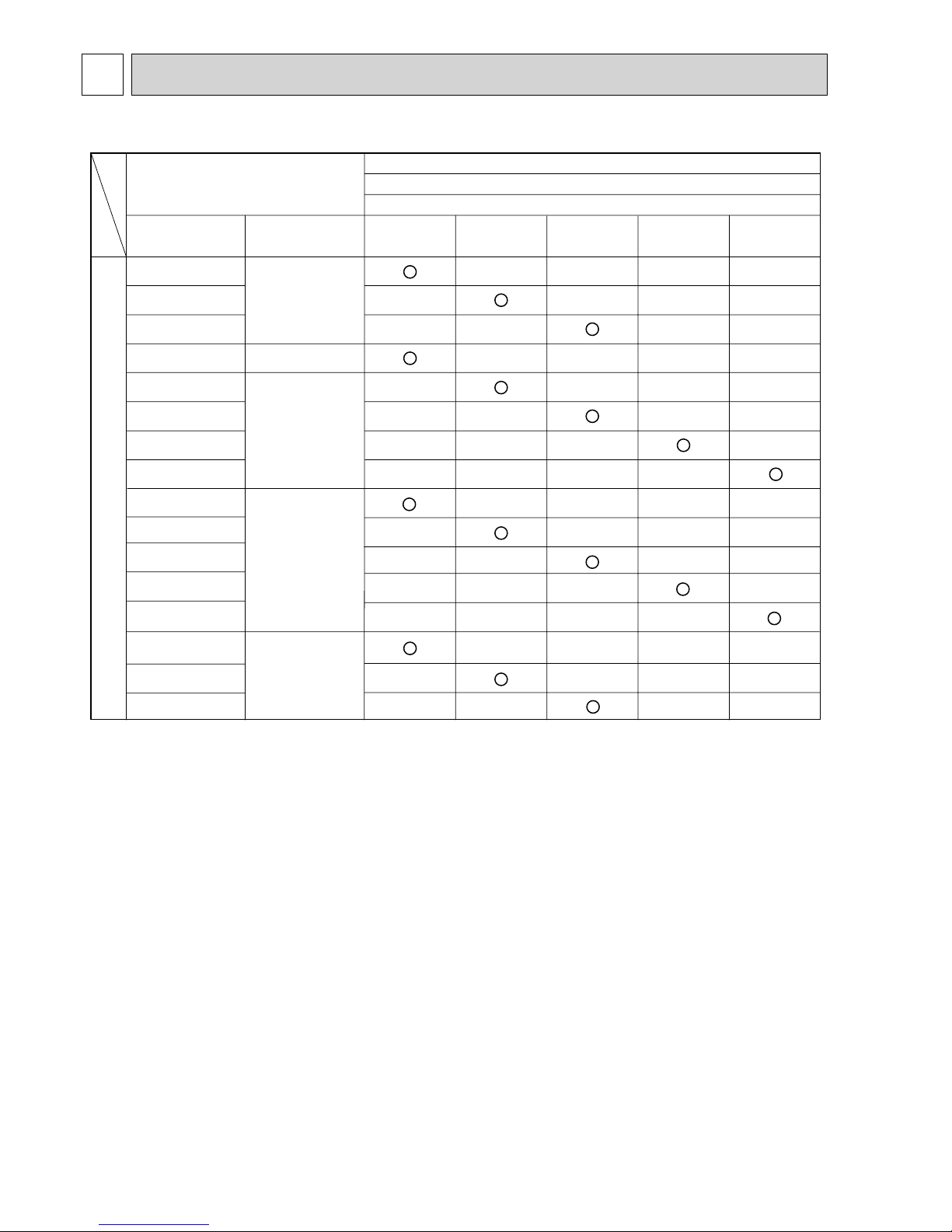
COMBINATION OF INDOOR AND OUTDOOR UNITS
Heat pump type
Outdoor unit
SUZ-
SLZ-KA25VA(L).TH
SLZ-KA35VA(L).TH
SLZ-KA50VA(L).TH
SEZ-KC25VA.W
SEZ-KA35VA.TH
SEZ-KA50VA.TH
SEZ-KA60VA.TH
SEZ-KA71VA.TH
SEZ-KD25VA(L).TH
SEZ-KD35VA(L).TH
SEZ-KD50VA(L).TH
SEZ-KD60VA(L).TH
SEZ-KD71VA(L).TH
MFZ-KA25VA-E1
MFZ-KA35VA-E1
MFZ-KA50VA-E1
—
—
—
—
—
—
—
—
—
—
—
—
—
—
—
—
—
—
—
—
—
—
—
—
—
—
—
—
—
—
—
—
—
—
—
—
—
—
—
—
—
—
—
—
—
—
—
—
—
—
—
—
—
—
—
—
—
—
—
—
—
—
—
—
OC320
—
OC321
OB409
Indoor unit
Service
Manual No.
Service Ref.
Heat pump without electric heater
KA25VA(H).TH
KA25VA(H)R1.TH
KA60VA
(1)
.TH
KA60VAR2.TH
KA71VA
(1)
.TH
KA50VA
(1)
.TH
KA50VAR2.TH
HWE0711
KA35VA(H).TH
KA35VA(H)R1.TH
(NOTE) • Please refer to the service manual of indoor unit or the technical data book for the combination data.
• Only MFZ-KA·VA series can be connected to SUZ-KA·VAH series.
1-1. INDOOR UNIT SERVICE MANUAL
1-2. TECHNICAL DATA BOOK
OCS03
OC322G

3
2
TECHNICAL CHANGES
SUZ-KA50VA1.TH SUZ-KA50VAR2.TH
SUZ-KA60VA
1.TH SUZ-KA60VAR2.TH
1. OUTDOOR ELECTRONIC CONTROL P.C. BOARD has been changed.
2. Compressor has been changed. (SNB130FLDH(1)
→ SNB130FGBH)
3. High pressure switch has been added. (SUZ-KA60VAR2.TH)
4. Thermistors (RT61, 62, 64, 65, 68) have been changed. (SUZ-KA50VAR2.TH)
SUZ-KA50VA.TH SUZ-KA50VA1.TH
SUZ-KA60VA.TH SUZ-KA60VA
1.TH
SUZ-KA71VA.TH SUZ-KA71VA
1.TH
1. OUTDOOR ELECTRONIC CONTROL P.C. BOARD has been changed.
2. Max. height difference 15m
→
30m (Except when combined with MFZ).
3. Guaranteed operating range
Lower limit (Cooling/Outdoor) -10:DB
→
-15:DB (Except when combined with MFZ)
SUZ-KA25VA.TH
SUZ-KA35VA.TH
Lower limit (Heating/Outdoor) -10:DB → -15:DB.
SUZ-KA35VAH.TH
Defrost finish temperature has been changed (Refer to 11. SERVICE FUNCTIONS).
SUZ-KA25VA.TH SUZ-KA25VAR1.TH
SUZ-KA25VAH.TH SUZ-KA25VAHR1.TH
SUZ-KA35VA.TH SUZ-KA35VAR1.TH
SUZ-KA35VAH.TH SUZ-KA35VAHR1.TH
1. Inverter P.C. board and Power P.C. board have been changed.
2. Refrigerant circuit has been changed.
• Compressor has been changed. (KNB073FDVH(C) → KNB073FFDHC : SUZ-KA25VA(H)R1.TH)
(KNB092FCAH → KNB092FFAHC : SUZ-KA35VA(H)R1.TH)
• Muffler of liquid pipe side has been deleted.
• Muffler of gas pipe side has been changed.
• Capillary tube of liquid pipe side has been added. (SUZ-KA35VA(H)R1.TH)
• 4-way valve and R.V. coil have been changed.
• Specification of LEV body has been changed.
• Stop valve has been changed.
3. Precharged refrigerant amount has been changed. (900g → 800g : SUZ-KA25VA(H)R1.TH)
4. Fan motor has been changed. (RC0J50-AL → RC0J50-DB)
5. Outdoor heat exchanger temperature thermistor (RT68) has been added.
SUZ-A09VR.TH SUZ-KA25VA.TH
SUZ-A12VR.TH SUZ-KA35VA.TH
1. Indication of capacity has been changed.(BTU base → kW base)
2. Control method between indoor and outdoor unit has been changed.
3. Power supply method has been changed (change to supply from outdoor unit).
4. Terminal block for power supply has been added.
5. Power P.C. board has been changed.
6. Inverter P.C. board has been changed.
7. Refrigerant circuit has been changed.
•
Compressor has been changed. (KNB073FBVH → KNB073FDVH:SUZ-KA25VA) (KNB092FAAH → KNB092FCAH:SUZ-KA35VA)
• Specification and position of muffler have been changed.
• Path of outdoor heat exchanger has been changed.
• 4-way valve and R.V. coil have been changed.
• Stop valve has been changed.
8. Fan motor has been changed. (AC → DC)
9. Shape of grille has been changed.
10. Shape of service panel has been changed.
11. Shape of propeller has been changed.
12. Symbol on terminal block has been changed (to S1/S2/S3).
OC322G
4
Refrigerant
oil
Refrigerant
New refrigerant
R410A
HFC-32: HFC-125 (50%:50%)
Pseudo-azeotropic refrigerant
Not included
A1/A1
72.6
-51.4
1.557
64
Non combustible
0
1730
From liquid phase in cylinder
Possible
Incompatible oil
None
None
Previous refrigerant
R22
R22 (100%)
Single refrigerant
Included
A1
86.5
-40.8
0.94
44.4
Non combustible
0.055
1700
Gas phase
Possible
Compatible oil
Light yellow
None
Refrigerant
Composition (Ratio)
Refrigerant handling
Chlorine
Safety group (ASHRAE)
Molecular weight
Boiling point ()
Steam pressure [25](Mpa)
Saturated steam density [25](Kg/*)
Combustibility
ODP +1
GWP +2
Refrigerant charge method
Additional charge on leakage
Kind
Color
Smell
+1: Ozone Depletion Potential : based on CFC-11
+2: Global Warming Potential : based on CO
2
SUZ-A18VR SUZ-KA50VA.TH
SUZ-A24VR SUZ-KA60VA.TH
1. Indication of capacity has been changed.(BTU base → kW base)
2. Power supply method has been changed (change to supply from outdoor unit).
3. Outdoor electronic control P.C. board has been changed.
4. Noise filter P.C. board has been changed.
5. Length of fan motor lead wire has been changed.
6. Shape of relay panel has been changed.
7. Symbol on terminal block has been changed (to S1/S2/S3).
8. Control method between indoor and outdoor unit has been changed.
INFORMATION FOR THE AIR CONDITIONER WITH R410A REFRIGERANT
• This room air conditioner adopts an HFC refrigerant (R410A) which never destroys the ozone layer.
• Pay particular attention to the following points, though the basic installation procedure is same as that for R22 conditioners.
1 As R410A has working pressure approximate 1.6 times as high as that of R22, some special tools and piping parts/
materials are required. Refer to the table below.
2 Take sufficient care not to allow water and other contaminations to enter the R410A refrigerant during storage and
installation, since it is more susceptible to contaminations than R22.
3 For refrigerant piping, use clean, pressure-proof parts/materials specifically designed for R410A. (Refer to 2. Refrigerant
piping.)
4 Composition change may occur in R410A since it is a mixed refrigerant. When charging, charge liquid refrigerant to prevent
composition change.
OC322G
5
-30 -20 -10 0 10 20
30
40 50 60
-0.5
0.0
0.5
1.0
1.5
2.0
2.5
3.0
3.5
4.0
(MPa [Gauge])
R410A
R22
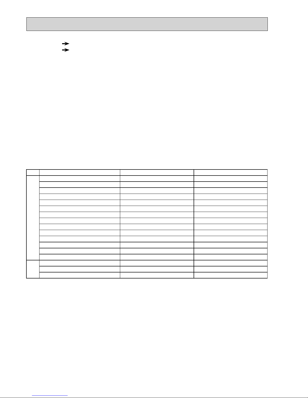
Conversion chart of refrigerant temperature and pressure
Saturated liquid pressure
()
NOTE: The unit of pressure has been changed to MPa on the
international system of units (SI unit system).
The conversion factor is: 1 (MPa [Gauge]) =10.2 (kgf/cm2 [Gauge])
R410A tools Can R22 tools be used?
Gas leak detector
R410A has high pressures beyond the measurement range of existing
gauges. Port diameters have been changed to prevent any other refrigerant
from being charged into the unit.
Hose material and cap size have been changed to improve the pressure
resistance.
Dedicated for HFC refrigerant.
6.35 mm and 9.52 mm
Description
Clamp bar hole has been enlarged to reinforce the spring strength in the tool.
Provided for flaring work (to be used with R22 flare tool).
Provided to prevent the back flow of oil. This adapter enables you to use
vacuum pumps.
It is difficult to measure R410A with a charging cylinder because the
refrigerant bubbles due to high pressure and high-speed vaporization
No
No
No
Yes
Yes
New
New
New
Gauge manifold
Charge hose
Torque wrench
Flare tool
Flare gauge
Vacuum pump
adapter
Electronic scale for
refrigerant charging
No: Not substitutable for R410A Yes: Substitutable for R410A
No 12.7 mm and 15.88 mm
1. Tools dedicated for the air conditioner with R410A refrigerant
The following tools are required for R410A refrigerant. Some R22 tools can be substituted for R410A tools.
The diameter of the service port on the stop valve in outdoor unit has been changed to prevent any other refrigerant being
charged into the unit. Cap size has been changed from 7/16 UNF with 20 threads to 1/2 UNF with 20 threads.
NOTE : The unit of pressure has been changed to MPa on the international system of units (SI unit system).
The conversion factor is: 1 (MPa [Gauge]) =10.2 (kgf/cm2 [Gauge])
New Specification Current Specification
The incompatible refrigerant oil easily separates from
refrigerant and is in the upper layer inside the suction muffler.
Raising position of the oil back hole enables to back the
refrigerant oil of the upper layer to flow back to the
compressor.
Since refrigerant and refrigerant oil are compatible with
each other, refrigerant oil backs to the compressor through
the lower position oil back hole.
Compressor
Suction muffler
Oil back hole
Refrigerant oil
Refrigerant
Compressor
Suction muffler
Oil back hole
Refrigerant oil /Refrigerant
Compressor
OC322G
6
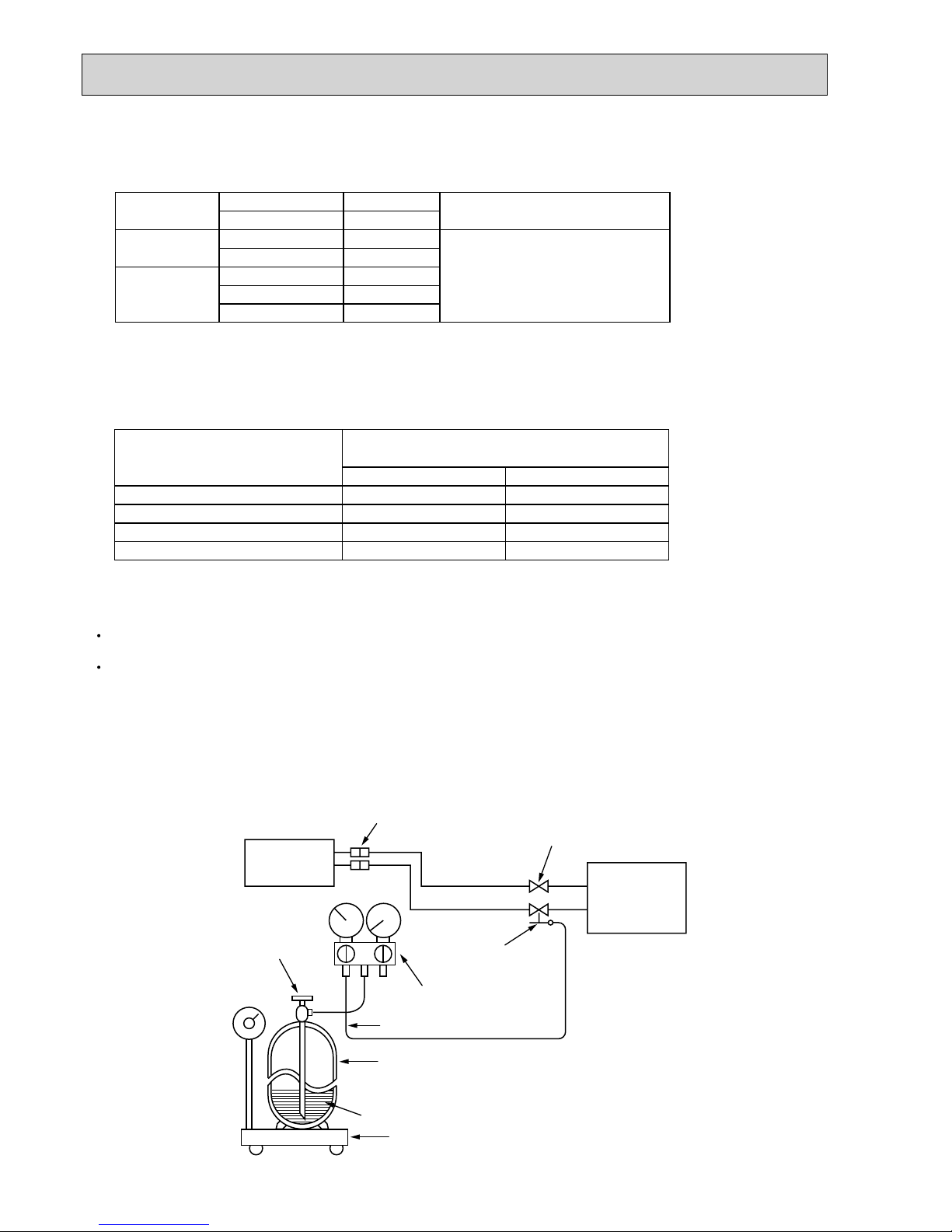
Electronic scale for refrigerant charging
Outdoor unit
Refrigerant gas
cylinder
operating valve
Refrigerant gas cylinder
for R410A with siphon
Refrigerant (liquid)
Service port
Gauge manifold
valve (for R410A)
Union
Liquid pipe
Gas pipe
Stop valve
Indoor unit
Charge hose (for R410A)
R410A
Pipe diameter (mm)
6.35
9.52
12.7
15.88
17
22
26
29
Dimension of flare nut (mm)
R22
17
22
24
27
• Use a copper pipe or a copper-alloy seamless pipe with a thickness of 0.8 mm. Never use any pipe with a thickness less
than 0.8mm, as the pressure resistance is insufficient.
2 Flaring work and flare nut
Flaring work for R410A pipe differs from that for R22 pipe.
For details of flaring work, refer to Installation manual “FLARING WORK”.
3. Refrigerant oil
Apply the special refrigerant oil (accessories: packed with indoor unit) to the flare and the union seat surfaces.
4. Air purge
Do not discharge the refrigerant into the atmosphere.
Take care not to discharge refrigerant into the atmosphere during installation, reinstallation, or repairs to the refrigerant circuit.
Use the vacuum pump for air purging for the purpose of environmental protection.
5. Additional charge
For additional charging, charge the refrigerant from liquid phase of the gas cylinder.
If the refrigerant is charged from the gas phase, composition change may occur in the refrigerant inside the cylinder and the
outdoor unit. In this case, ability of the refrigerating cycle decreases or normal operation can be impossible. However, charging the liquid refrigerant all at once may cause the compressor to be locked. Thus, charge the refrigerant slowly.
2. Refrigerant piping
1 Specifications
Use the refrigerant pipes that meet the following specifications.
Wall thicknessOutside diameter
Pipe
mm mm
For liquid
For gas
6.35
9.52
9.52
12.7
15.88
0.8
0.8
0.8
0.8
1.0
Heat resisting foam plastic
Specific gravity 0.045 Thickness
8 mm
Insulation material
OC322G
77
3
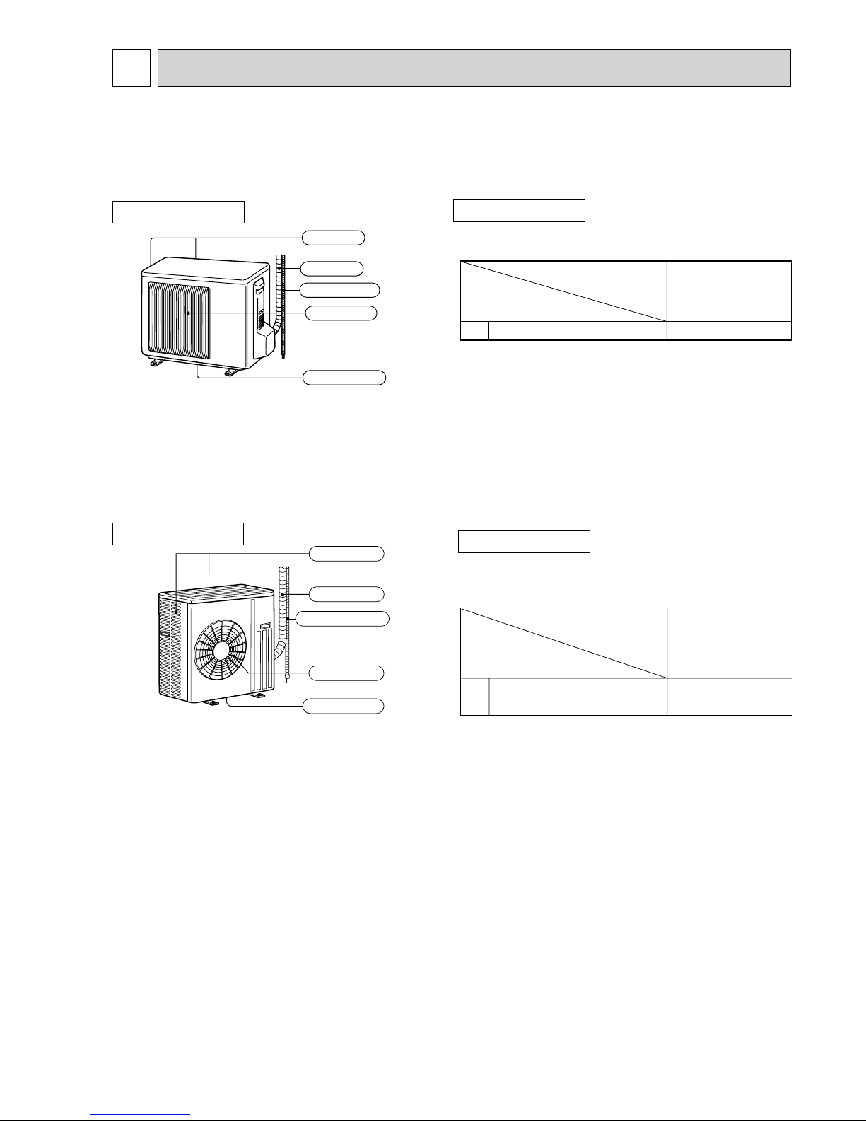
PART NAMES AND FUNCTIONS
OUTDOOR UNIT
Air inlet
Air outlet
Drain outlet
Piping
Drain hose
(back and side)
ACCESSORIES
Drain socket
1
SUZ-KA25VAR1.TH
SUZ-KA35VAR1.TH
SUZ-KA25VA.TH
SUZ-KA35VA.TH
SUZ-KA25VA.TH
SUZ-KA35VA.TH
SUZ-KA25VAH.TH
SUZ-KA35VAH.TH
OUTDOOR UNIT
Air inlet
Piping
Air outlet
(back and side)
Drain hose
Drain outlet
ACCESSORIES
Drain socket
Drain cap :33
1
2
SUZ-KA50VA
(1).TH
SUZ-KA60VA(1).TH
SUZ-KA71VA
(1).TH
SUZ-KA50VAR2.TH
SUZ-KA60VAR2.TH
SUZ-KA50VA.TH SUZ-KA50VA1.TH SUZ-KA50VAR2.TH
SUZ-KA60VA.TH SUZ-KA60VA
1.TH SUZ-KA60VAR2.TH
SUZ-KA71VA.TH SUZ-KA71VA
1.TH
SUZ-KA25VAR1.TH
SUZ-KA35VAR1.TH
SUZ-KA25VAHR1.TH
SUZ-KA35VAHR1.TH
OC322G
8
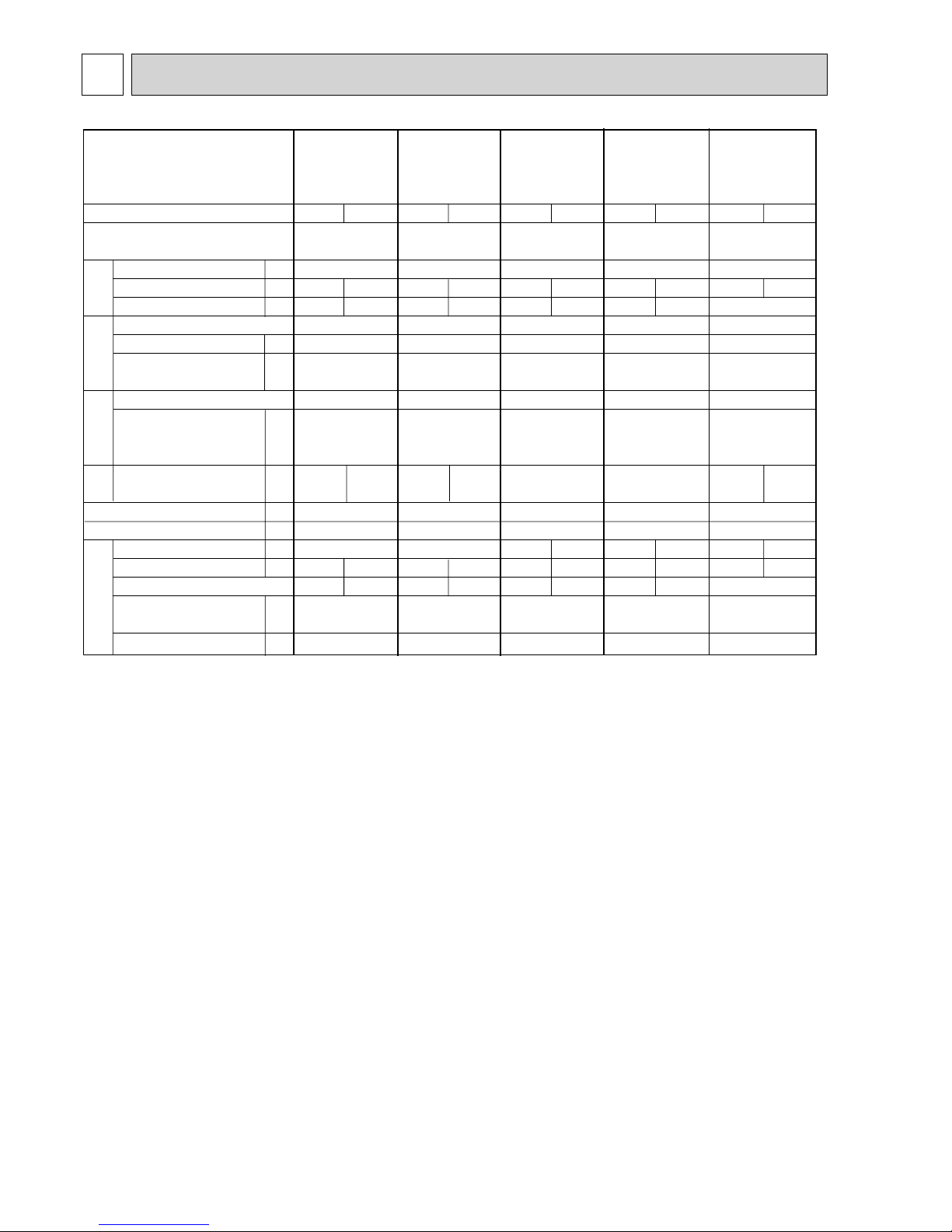
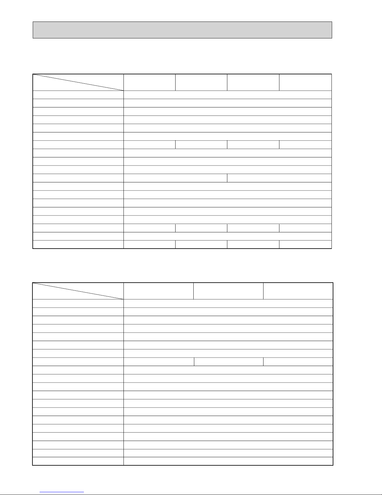
SPECIFICATION
4
Function
Power supply
Outdoor Service Ref.
Starting current *1
Compressor motor current *1
Fan motor current *1
Model
Output
Winding
resistance (at 20)
Model
Winding
resistance(at 20)
Air flow(High/Low+)
Dimensions WHD
Weight
Sound level
*1
Fan speed(High+/Low+, High+/Med+/Low+)
Fan speed regulator
Refrigerant filling
capacity(R410A)
Refrigerating oil (Model)
A
A
A
W
*/h
mm
kg
dB
rpm
kg
cc
Single phase
230V, 50Hz
3.65
KNB073FDVH(C)
550
U-V 1.53 U-W 1.53
V-W 1.53
RC0J50-AL
WHT-BLK 37.5
BLK-RED 37.5
RED-WHT 37.5
800%550%285
33
46
0.90
320 (NEO22)
Cooling
2.74
0.31
2,058
810+/650
+
2
880+/810+/650
+
3
810+/650
+
2
880+/810+/650
+
3
Heating
3.37
0.28
1,938
SUZ-KA25VA(H).TH
Compressor
Fan
motor
Special
remarks
Electrical
data
SUZ-KA25VA(H)R1.TH
Single phase
230V, 50Hz
3.65
KNB073FFDH(C)
550
U-V 1.70 U-W 1.70
V-W 1.70
RC0J50-DB
WHT-BLK 37.0
BLK-RED 37.0
RED-WHT 37.0
800%550%285
30
46
0.80
320 (NEO22)
Cooling
2.74
0.31
2,058
Heating
3.37
0.28
1,938
SUZ-KA50VA.TH
SUZ-KA50VA
1.TH
Single phase
230V, 50Hz
6.75
0.30
SNB130FLDH or SNB130FLDH1
850
U-V 0.45 U-W 0.45
V-W 0. 45
RC0J60-AA
WHT-BLK 15.2
BLK-RED 15.2
RED-WHT 15.2
840%850%330
53
2
1.60
FLDH: 450/FLDH1: 600(NEO22)
Cooling
6.45
2,940/1,650
+
53/51
+
800/480
+
Heating
6.05
2,940/2,210
+
55/53
+
800/620
+
Capa-
city
SUZ-KA35VA(H)R1.TH
840+/760
+
2
880+/800+/630
+
3
SUZ-KA35VA(H).TH
Single phase
230V, 50Hz
4.75
KNB092FCAH
650
U-V 0.49 U-W 0.49
V-W 0. 49
RC0J50-AL
WHT-BLK 37.5
BLK-RED 37.5
RED-WHT 37.5
2,004
800%550%285
37
1.05
320 (NEO22)
Cooling
4.22
0.33
47
Heating
4.42
0.33
48
840+/760
+
2
880+/800+/630
+
3
Single phase
230V, 50Hz
4.75
KNB092FFAH(C)
650
U-V 1.91 U-W 1.91
V-W 1.91
RC0J50-DB
WHT-BLK 37.0
BLK-RED 37.0
RED-WHT 37.0
2,004
800%550%285
33
1.05
320 (NEO22)
Cooling
4.22
0.33
47
Heating
4.42
0.33
48
NOTE : Test conditions are based on ISO 5151
Cooling : Indoor D.B. 27: W.B . 19:
Outdoor D.B. 35: W.B. 24:
Heating : Indoor D.B. 20: W.B. 15:
Outdoor D.B. 7: W.B. 6:
Refrigerant piping length (one way): 5m
*1 Measured under rated operating frequency.
w Reference value
OC322G
99
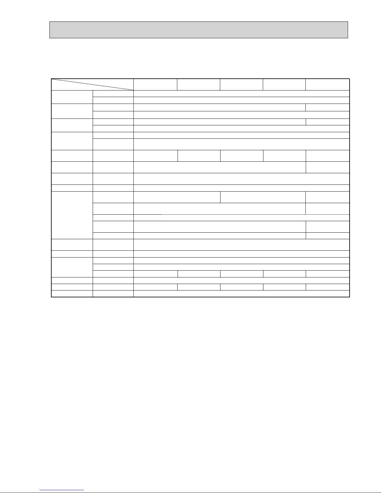
SUZ-KA50VAR2.TH
SUZ-KA60VA.TH
SUZ-KA60VA
1.TH
SUZ-KA71VA.TH
SUZ-KA71VA
1.TH
SUZ-KA60VAR2.TH
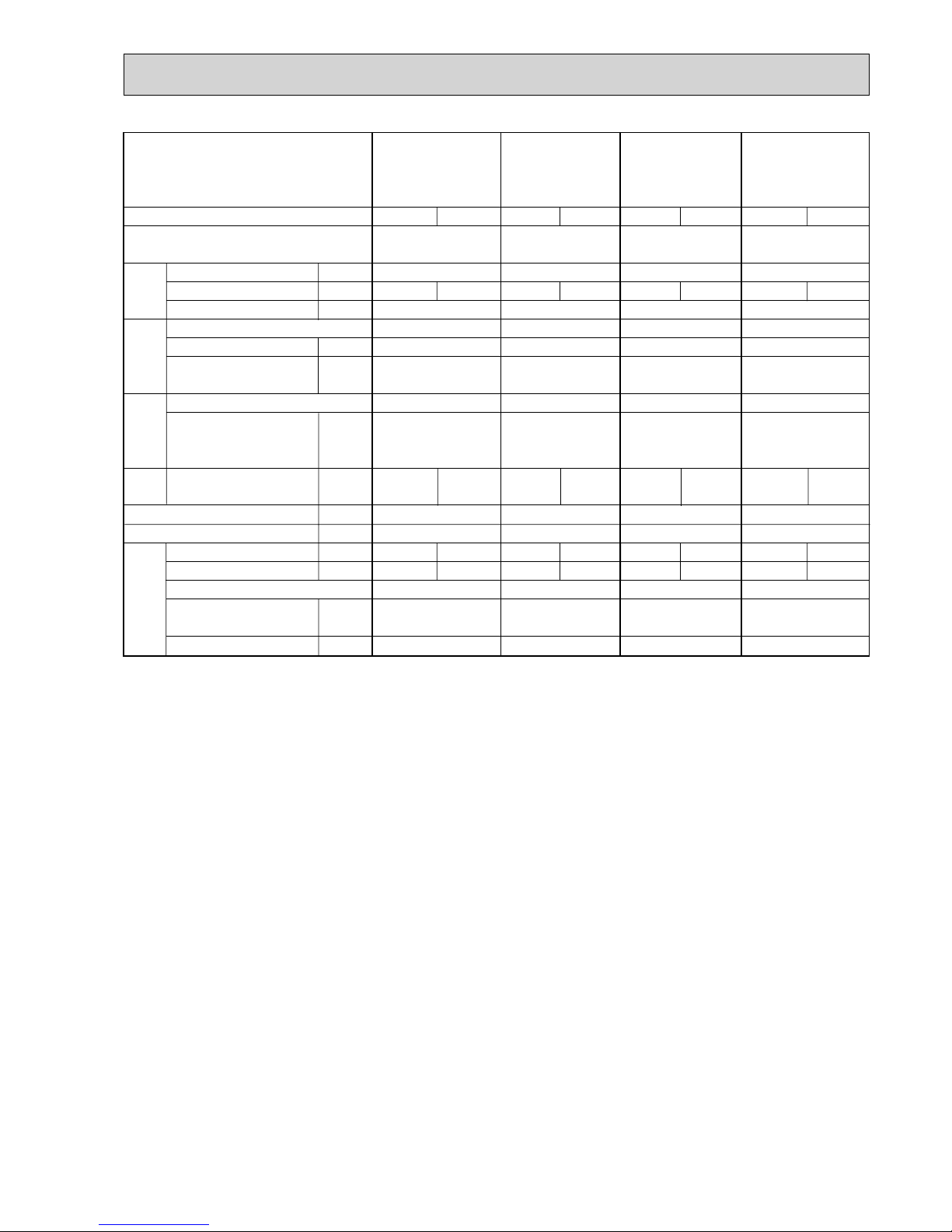
Function
Power supply
Outdoor Service Ref.
Starting current *1
Compressor motor current *1
Fan motor current *1
Model
Output
Winding
resistance (at 20)
Model
Winding
resistance(at 20)
Air flow(High/Low+)
Dimensions WHD
Weight
Sound level
*1
Fan speed(High+/Low+, High+/Med+/Low+)
Fan speed regulator
Refrigerant filling
capacity(R410A)
Refrigerating oil (Model)
A
A
A
W
* /h
mm
kg
dB
rpm
kg
cc
Compressor
Fan
motor
Special
remarks
Electrical
data
Single phase
230V, 50Hz
10.30
0.30
TNB220FMCH(T)
1300
U-V 1.41 U-W 1.41
V-W 1.41
RC0J60-AA
WHT-BLK 15.2
BLK-RED 15.2
RED-WHT 15.2
840%850%330
58
2
2.00
870 (NEO22)
Cooling
10.00
2,940/1650
+
53/51
+
800/480
+
Heating
9.60
2,940/2,210
+
55/53
+
800/620
+
Capa-
city
Single phase
230V, 50Hz
6.75
0.30
SNB130FGBH(T)
900
U-V 0.98 U-W 0.98
V-W 0. 98
RC0J60-AA
WHT-BLK 15.2
BLK-RED 15.2
RED-WHT 15.2
840%850%330
53
2
1.60
450 (NEO22)
Cooling
6.45
2,940/1,650
+
53/51
+
800/480
+
Heating
6.05
2,940/2,210
+
55/53
+
800/620
+
Single phase
230V, 50Hz
9.75
0.30
SNB130FLDH or SNB130FLDH1
850
U-V 0.45 U-W 0.45
V-W 0. 45
RC0J60-AA
WHT-BLK 15.2
BLK-RED 15.2
RED-WHT 15.2
840%850%330
53
2
1.80
FLDH: 450/FLDH1: 600 (NEO22)
Cooling
8.05
2,940/1650
+
53/51
+
800/480
+
Heating
9.45
2,940/2,210
+
55/53
+
800/620
+
Single phase
230V, 50Hz
9.75
0.30
SNB130FGBH(T)
900
U-V 0.98 U-W 0.98
V-W 0.98
RC0J60-AA
WHT-BLK 15.2
BLK-RED 15.2
RED-WHT 15.2
840%850%330
53
2
1.80
450 (NEO22)
Cooling
8.05
2,940/1650
+
53/51
+
800/480
+
Heating
9.45
2,940/2,210
+
55/53
+
800/620
+
NOTE : Test conditions are based on ISO 5151
Cooling : Indoor D.B. 27: W.B . 19:
Outdoor D.B. 35: W.B. 24:
Heating : Indoor D.B. 20: W.B. 15:
Outdoor D.B. 7: W.B. 6:
Refrigerant piping length (one way): 5m
*1 Measured under rated operating frequency.
w Reference value
OC322G
10
Model
Item
Current transformer
Current transformer
Smoothing capacitor
Diode module
Fuse
Fuse
Defrost heater
Intelligent power module
Expansion valve coil
Reactor
Current-detecting resistor
Current-detecting resistor
Current-limiting resistor
Terminal block
Relay
Relay
Relay
R.V. coil
Heater protector
SUZ-KA25VA.TH
(CT)
(CT761, CT781)
(
C63A, C63B, C63C
)
(DB61, DB65)
(F61)
(F71, F801, F901)
(H)
(IPM)
(LEV)
(L61)
(R61)
(R831)
(
R64A, R64B
)
(TB1,TB2)
(X63)
(X64)
(X66)
(21S4)
(26H)
SUZ-KA25VAH.TH SUZ-KA35VA.TH SUZ-KA35VAH.TH
ETA19Z59BZ
ETQ19Z71AY
620420V
D25×B60
250V 20A
250V 3.15A
PS21244-A-203
CAD-MD12ME 12VDC
10A 23.0mH
25m 5W
5.1 5W
3P
G5NB-1a
G4A-1A-PS
STF-01AJ503
—
—
—
230V 130W
G5NB-1a
Open 45
—
—
—
230V 130W
G5NB-1a
Open 45
45m 5W (1 element) 50m 5W (2 elements)
Specifications and rating conditions of main electric parts
Model
Item
Smoothing capacitor
Current transformer
Current transformer
Fuse
Fuse
Fuse
Intelligent power module
High pressure switch
Intelligent power module
Reactor
Expansion valve coil
Power factor controller
Resistor
Resistor
Resistor
Solenoid coil relay
Terminal block
Terminal block
Relay
R.V. coil
(CB1,2,3)
(CT1,2)
(CT61)
(F64)
(F801)
(F911)
(HC930)
(HPS)
(IPM)
(L)
(LEV)
(PFC)
(R64A,B)
(R937A,B)
(RS1~4)
(SSR61)
(TB1)
(TB2)
(X64)
(21S4)
560 450V
ETQ19Z68AY
ETQ19Z53AY
250V 2A
250V 3.15A
250V 1A
PS21661-RZ
PS21244-A
340μH 20A
DC12V
PS51259-A
1010W
1.12W 2%
0.04 7W
TLP3506
3P
3P
G4A
AC 220 - 240V
SUZ-KA50VA.TH
SUZ-KA50VA
1.TH
SUZ-KA60VA.TH
SUZ-KA60VA
1.TH
SUZ-KA60VAR2.TH
SUZ-KA71VA.TH
SUZ-KA71VA
1.TH
— ACB-DB156ACB-DB156 (for R2)
SUZ-KA25VA.TH SUZ-KA25VAH.TH
SUZ-KA35VA.TH SUZ-KA35VAH.TH
SUZ-KA50VA.TH SUZ-KA50VA
1.TH
SUZ-KA60VA.TH SUZ-KA60VA
1.TH SUZ-KA60VAR2.TH
SUZ-KA71VA.TH SUZ-KA71VA
1.TH
OC322G
11
SUZ-KA25VAR1.TH SUZ-KA25VAHR1.TH
SUZ-KA35VAR1.TH SUZ-KA35VAHR1.TH
SUZ-KA50VAR2.TH
Model
Item
Current
transformer
20 A(CT)
15 A(CT761, CT781)
Smoothing
capacitor
620 μF 420 V
(C61)
Diode module
25 A 600 V15 A 600 V(DB61)
(DB65)
Fuse
T20AL250V(F61)
(F701, F801,
F901)
T3.15AL250V
Defrost heater
230 V
130 W
—
230 V
130 W
Intelligent power
module
(IPM)
Expansion valve
coil
DC 12 V(LEV)
23 mH(L61)Reactor
Currentdetecting
resistor
(R61)
45 mΩ 5 W
(1 element) (2 elements)
—
(R61,R62)
(2 elements)
(R825)
(R937, R938,
R939)
—
—(R937A, R937B)
Current-limiting
PTC thermistor
(PTC64,
PTC65)
3 P(TB1, TB2)Terminal block
Relay
(X63)
(X64)
(21S4)R.V. coil
(TR821)IGBT
(H)
(X66)
Heater protector
(26H)
25 A 600 V
15 A 600 V 20 A 600 V
100 mΩ 5 W
180 mΩ 5 W
25 mΩ 5 W
430 mΩ 2 W
1.1 Ω 2 W
33 Ω
3 A 250 V
20 A 250 V
AC 220 - 240 V
30 A 600 V
(C62, C63)
620
μF 420 V
——
—
3 A 250 V
—
3 A 250 V
——
Open 45°C
—
Open 45°C
——
—
SUZ-KA25VAR1.TH SUZ-KA25VAHR1.TH
SUZ-KA35VAR1.TH SUZ-KA35VAHR1.TH
SUZ-KA50VAR2.TH
OC322G
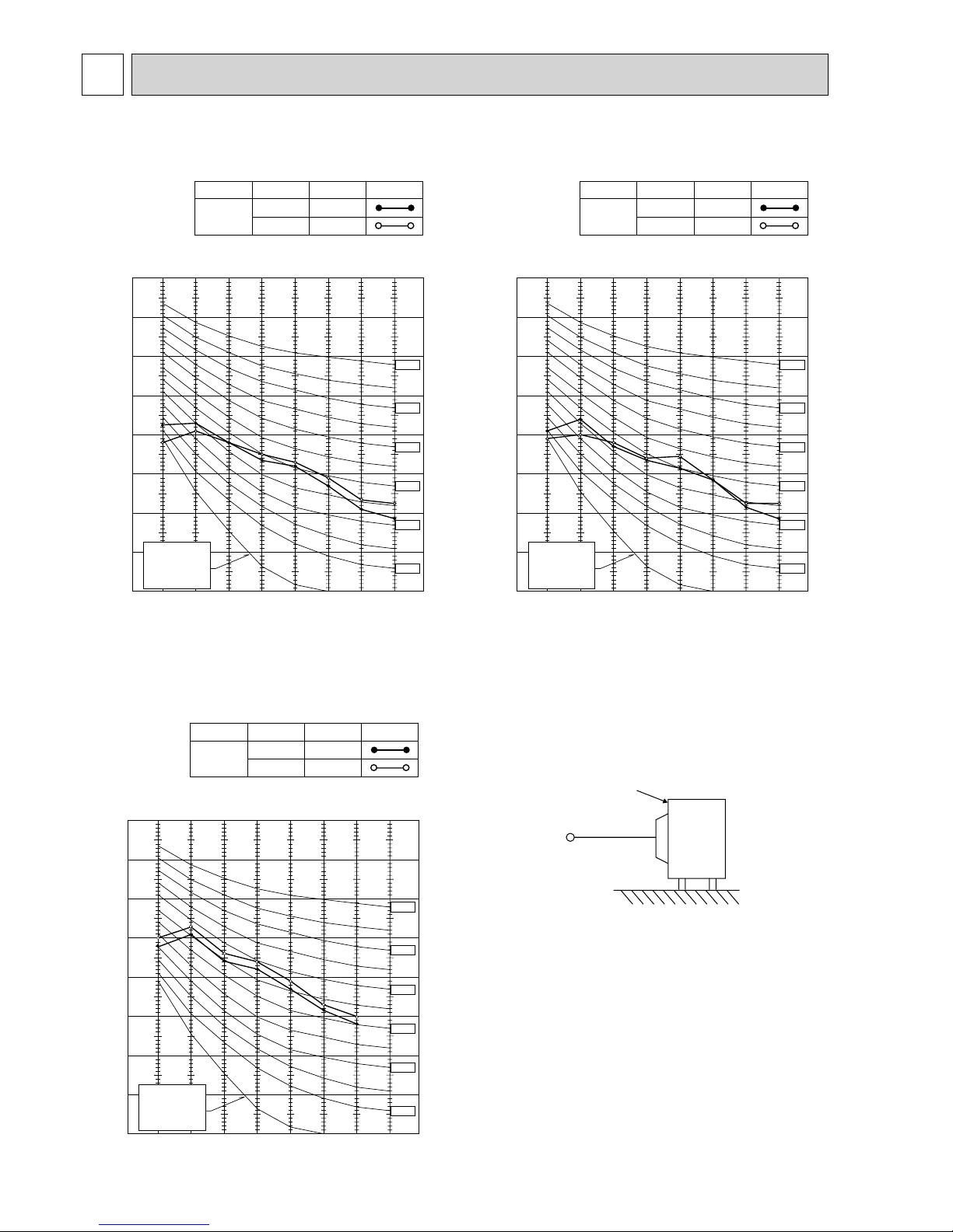
12
NOISE CRITERIA CURVES
5
90
80
70
60
50
40
30
20
10
63 125 250 500 1000 2000 4000 8000
NC-60
NC-50
NC-40
NC-30
NC-20
NC-70
OCTAVE BAND SOUND PRESSURE LEVEL, dB re 0.0002 MICRO BAR
BAND CENTER FREQUENCIES, Hz
APPROXIMATE
THRESHOLD OF
HEARING FOR
CONTINUOUS
NOISE
COOLING
FUNCTION
SPL(dB(A))
LINE
High
Med.
FAN SPEED
HEATING
46
46
Test conditions,
Cooling : Dry-bulb temperature 35Wet-bulb temperature (24)
Heating : Dry-bulb temperature 7Wet-bulb temperature 6
SUZ-KA25VA.TH
SUZ-KA25VAH.TH
90
80
70
60
50
40
30
20
10
63 125 250 500 1000 2000 4000 8000
NC-60
NC-50
NC-40
NC-30
NC-20
NC-70
OCTAVE BAND SOUND PRESSURE LEVEL, dB re 0.0002 MICRO BAR
BAND CENTER FREQUENCIES, Hz
APPROXIMATE
THRESHOLD OF
HEARING FOR
CONTINUOUS
NOISE
COOLING
FUNCTION
SPL(dB(A))
LINE
FAN SPEED
HEATING
47
48
Test conditions,
Cooling : Dry-bulb temperature 35Wet-bulb temperature (24)
Heating : Dry-bulb temperature 7Wet-bulb temperature 6
OUTDOORUNIT
MICROPHONE
1m
High
Med.
SUZ-KA35VA.TH
SUZ-KA35VAH.TH
COOLING
FUNCTION
SPL(dB(A)) LINE
High
FAN SPEED
HEATING
53
55
90
80
70
60
50
40
30
20
10
63 125 250 500 1000 2000 4000 8000
NC-60
NC-50
NC-40
NC-30
NC-20
NC-70
BAND CENTER FREQUENCIES, Hz
Test conditions,
Cooling : Dry-bulb temperature 35Wet-bulb temperature (24)
APPROXIMATE
THRESHOLD OF
HEARING FOR
CONTINUOUS
NOISE
Heating : Dry-bulb temperature 7Wet-bulb temperature 6
OCTAVE BAND SOUND PRESSURE LEVEL, dB re 0.0002 MICRO BAR
SUZ-KA50VA.TH SUZ-KA50VA1.TH SUZ-KA50VAR2.TH
SUZ-KA60VA.TH SUZ-KA60VA
1.TH SUZ-KA60VAR2.TH
SUZ-KA71VA.TH SUZ-KA71VA
1.TH
SUZ-KA25VAR1.TH
SUZ-KA25VAHR1.TH
SUZ-KA35VAR1.TH
SUZ-KA35VAHR1.TH
OC322G
13
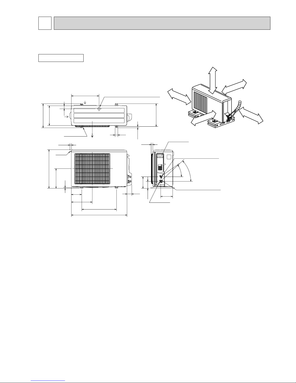
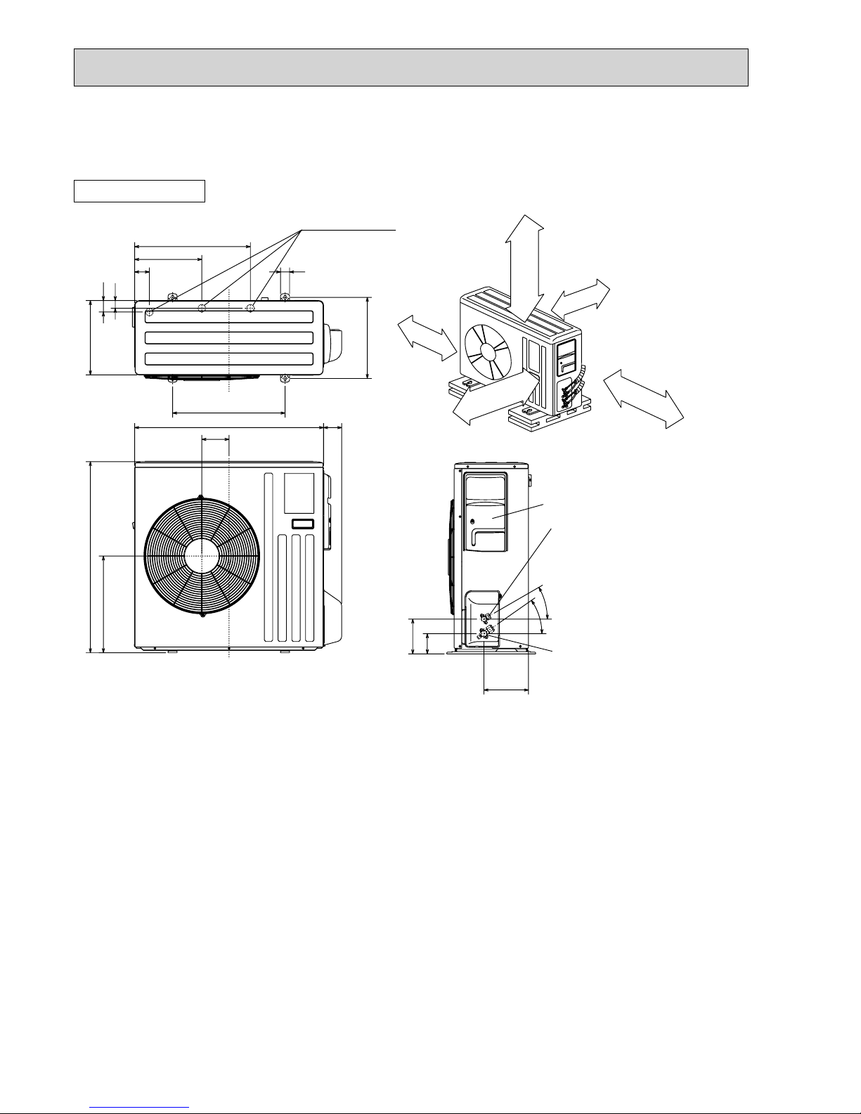
6
OUTLINES AND DIMENSIONS
10
69
800
302.5
500 Bolt pitch for installation
150
22.3
Handle
550
280
164.5
99.5
170.5
23
Service panel
Service port
285
344.5
44
400
Air in
Air out
Air in
17.5
Bolt pitch for
installation
304~325
40
Liquid refrigerant pipe joint
Refrigerant pipe (flared) :6.35
Gas refrigerant pipe joint
Refrigerant pipe (flared) :9.52
43
35
2 holes 10×21
Drain hole :33 (SUZ-KA25/KA35VAH)
REQUIRED SPACE
Basically open 100mm or more
without any obstruction in front
and on both sides of the unit.
350mm or more
200mm or more
100mm or more
100mm or more
Open two sides of left,
right, or rear side.
Drain hole :42 (SUZ-KA25/KA35VA)
Unit: mm
OUTDOOR UNIT
SUZ-KA25VA.TH SUZ-KA25VAH.TH SUZ-KA25VAR1.TH SUZ-KA25VAHR1.TH
SUZ-KA35VA.TH SUZ-KA35VAH.TH SUZ-KA35VAR1.TH SUZ-KA35VAHR1.TH
OC322G
14
Unit: mm
30
35
155
90
198
40
515
299
66
34
51
330
360
850
430
500
80
121
840
Open as a rule
500mm or more if
the front and both
sides are open
100mm or more
200mm or more if
there are obstacles
to both sides
Open as a rule
500mm or more if the back,
both sides and top are open
350mm or more
100mm or more
Service panel
Gas refrigerant
pipe joint
Refrigerant pipe(flared)
:12.7·····(SUZ-KA50VA)
:15.88···(SUZ-KA60/KA71VA)
Liquid refrigerant
pipe joint
Refrigerant pipe(flared)
:6.35·····(SUZ-KA50/KA60VA)
:9.52·····(SUZ-KA71VA)
REQUIRED SPACE
Drain holes :33
OUTDOOR UNIT
SUZ-KA50VA.TH SUZ-KA50VA1.TH SUZ-KA50VAR2.TH
SUZ-KA60VA.TH SUZ-KA60VA
1.TH SUZ-KA60VAR2.TH
SUZ-KA71VA.TH SUZ-KA71VA
1.TH
OC322G
1515
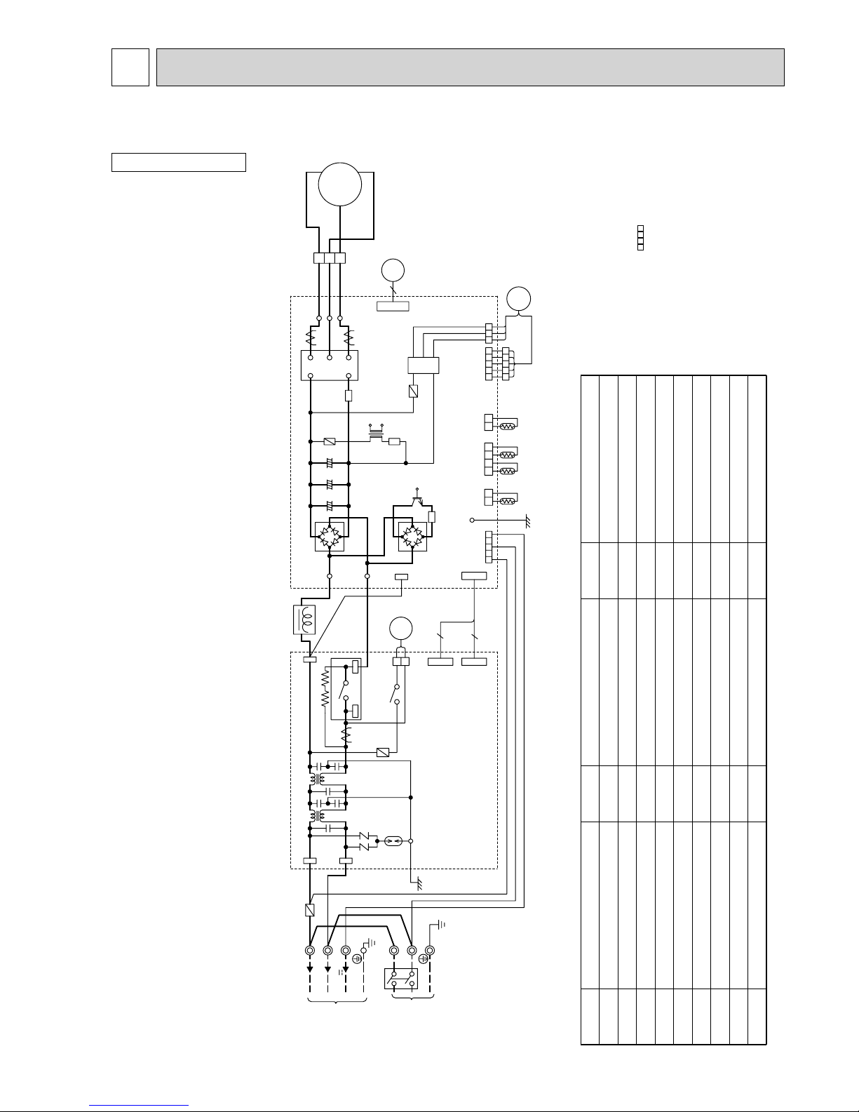
7
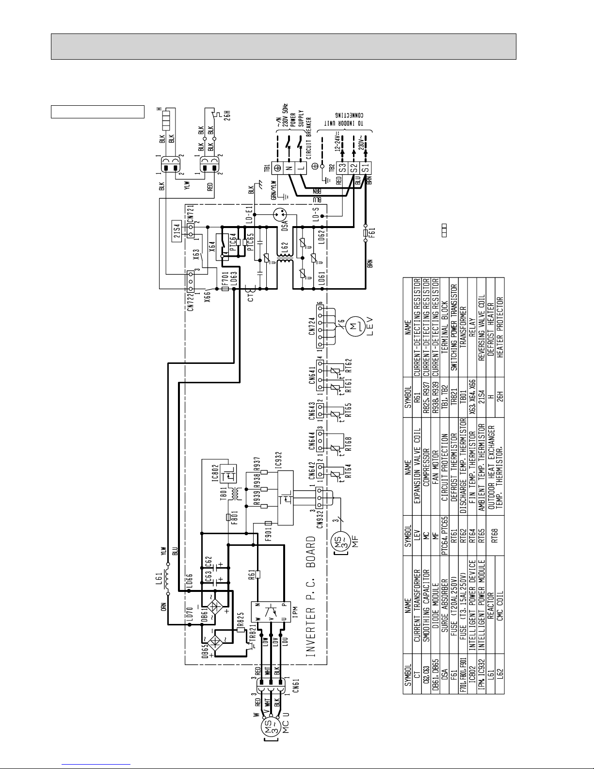
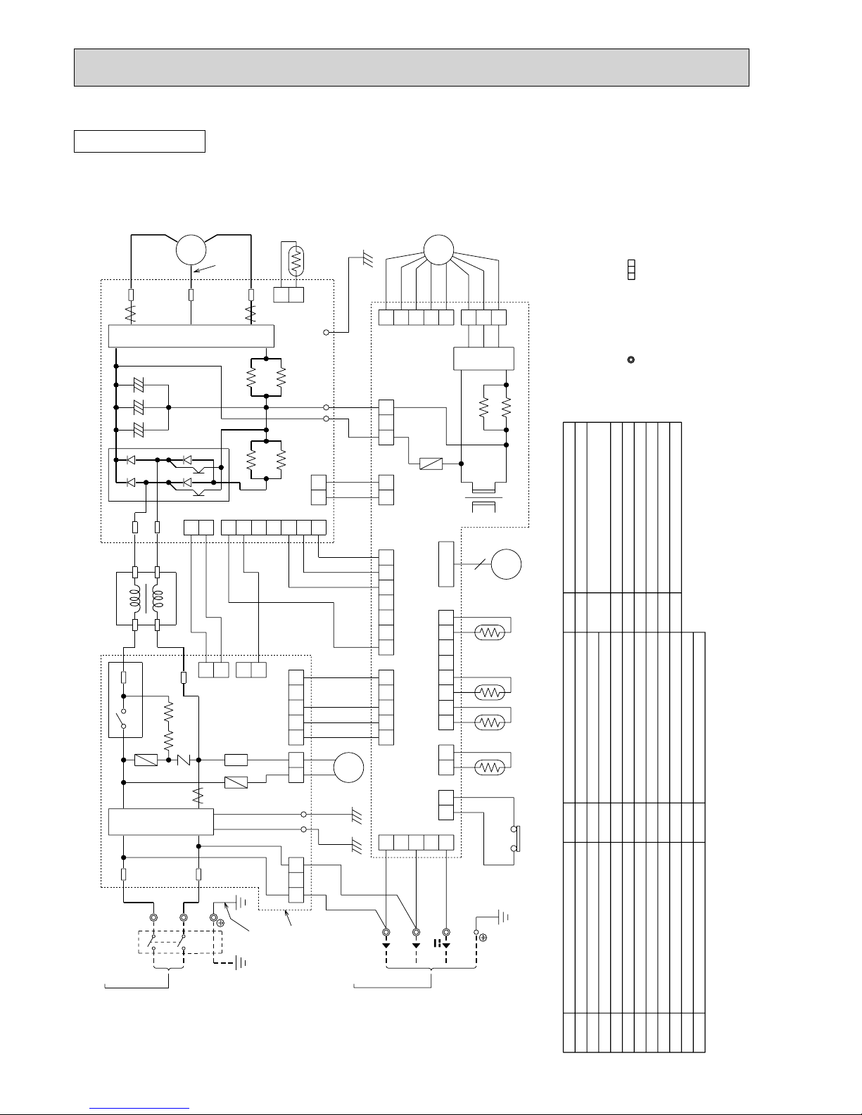
WIRING DIAGRAM
OUTDOOR UNIT
SUZ-KA25VA.TH
SUZ-KA35VA.TH
SYMBOL
CT,CT761,CT781
C63A,C63B,C63C
DB61,DB65
DSA61
F61
F71
F801,F901
IC801
IPM,IC932
SYMBOL
L61
L62,L63MCMF
NR63,NR64
RT61
RT62
RT64
RT65
SYMBOL
R61,R831
R64A,R64B
TB1,TB2
TR821
T801
X63,X64
21S4
LEV
NAME
CURRENT TRANSFORMER
SMOOTHING CAPACITOR
DIODE MODULE
SURGE ABSORBER
FUSE (T20AL250V)
FUSE (T3.15AL250V)
FUSE (T3.15AL250V)
INTELLIGENT POWER DEVICE
INTELLIGENT POWER MODULE
NAME
REACTOR
CMC COIL
COMPRESSOR
OUTDOOR FAN MOTOR
VAR ISTO R
DEFROST THERMISTOR
DISCHARGE TEMPERATURE THERMISTOR
FIN TEMPERATURE THERMISTOR
AMBIENT TEMPERATURE THERMISTOR
NAME
CURRENT-DETECTING RESISTOR
CURRENT-LIMITING RESISTOR
TERMINAL BLOCK
SWITCHING POWER TRANSISTOR
TRANSFORMER
RELAY
REVERSING VALVE COIL
EXPANSION VALVE COIL
NOTES:1. About the indoor side electric wiring, refer to
the indoor unit electric wiring diagram for
servicing.
2. Use copper conductors only. (For field wiring)
3. Symbols below indicate.
/: Terminal block, : Connector
MODELS WIRING DIAGRAM
+++
F61
GRN
~/N
230V~
12-24V
230V 50Hz
CIRCUIT BREAKER
PE
RED
BLU
WHITE
GRN/YLW
TB1
POWER
SUPPLY
L
N
TB2
S3
S1
TO INDDOR UNIT
CONNECTING
S2
RED
BLU
WHT
NR63
LDE
4
6
CN726
CN727
TB800
C63B
POWER P.C. BOARD
INVERTER P.C. BOARD
21S4
X63
CN721
1
2
L61
TAB63
3
LD69
RT61 RT62 RT64RT65
CN642
CN641
CN643
21213412
GRN
231
CN601
45
IC801
F901
IC932
CN931
315
42
1
2
3
CN932
5
42
13
MF
LD-V
LD-W
LD-U
3
1
WHT
BLK
RED
RED
V
BLK
WHT
W
U
wc
CN61
IPM
CT781
CT761
2
CN724
LEV
6
R61
N
U
V
W
P
F801
C63C
R831
DB65
DB61
TR821
C63A
T801
LDY
CN725
BLK
LD70
BLK
L63
NR64
DSA61
CT
TAB61
L62
X64
4
F71
TAB62
BLK
BLU
R64AR64B
WHT
OC322G
16
OUTDOOR UNIT
SUZ-KA25VAR1.TH
SUZ-KA35VAR1.TH
NOTES:1. About the indoor side electric wiring, refer to
the indoor unit electric wiring diagram for
servicing.
2. Use copper conductors only. (For field wiring)
3. Symbols below indicate.
: Terminal block
OC322G
17
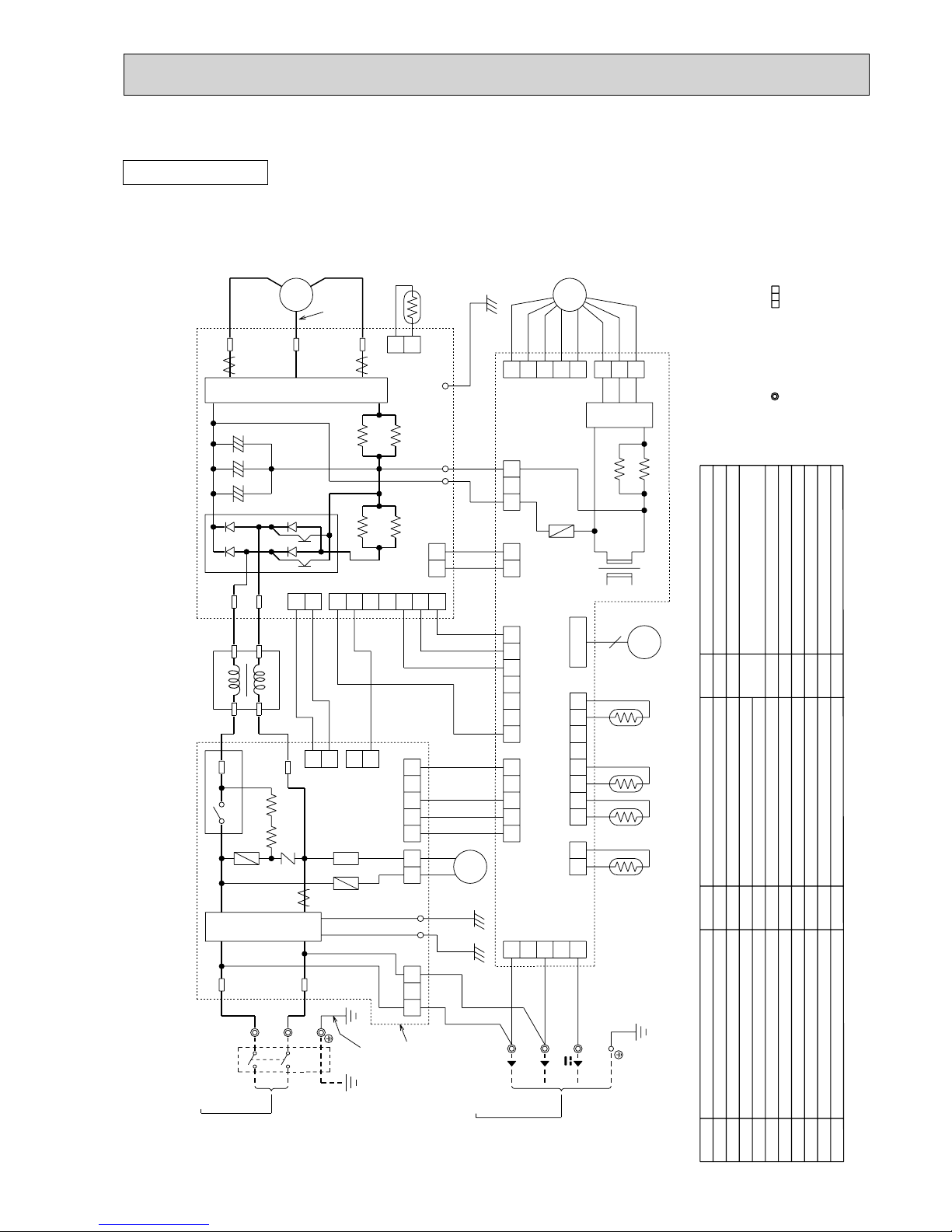
OUTDOOR UNIT
SUZ-KA25VAH.TH
SUZ-KA35VAH.TH
SYMBOL
CT,CT761,CT781
C63A,C63B,C63C
DB61,DB65
DSA61
F61
F71
F801,F901
IC801
IPM,IC932
LEV
SYMBOL
L61
L62,L63MCMF
NR63,NR64
RT61
RT62
RT64
RT65
R61,R831
SYMBOL
R64A,R64B
TB1,TB2
TR821
T801
X63,X64,X66
21S4H26H
NAME
CURRENT TRANSFORMER
SMOOTHING CAPACITOR
DIODE MODULE
SURGE ABSORBER
FUSE (T20AL250V)
FUSE (T3.15AL250V)
FUSE (T3.15AL250V)
INTELLIGENT POWER DEVICE
INTELLIGENT POWER MODULE
EXPANSION VALVE COIL
NAME
REACTOR
CMC COIL
COMPRESSOR
OUTDOOR FAN MOTOR
VAR ISTO R
DEFROST THERMISTOR
DISCHARGE TEMPERATURE THERMISTOR
FIN TEMPERATURE THERMISTOR
AMBIENT TEMPERATURE THERMISTOR
CURRENT-DETECTING RESISTOR
NAME
CURRENT-LIMITING RESISTOR
TERMINAL BLOCK
SWITCHING POWER TRANSISTOR
TRANSFORMER
RELAY
REVERSING VALVE COIL
DEFROST HEATER
HEATER PROTECTOR
NOTES:1. About the indoor side electric wiring, refer to
the indoor unit electric wiring diagram for
servicing.
2. Use copper conductors only. (For field wiring)
3. Symbols below indicate.
/: Terminal block, : Connector
MODELS WIRING DIAGRAM
IC932
F901
CT
4
3
NR64 NR63
GRN
DSA61
LDE
23145
CN601
LDY
GRN
MF
RT65 RT64RT62RT61
3
12 4
5
21
3
212 4
5
1
3
CN931
CN932
431212
CN643
CN641 CN642
312
X66
CN722
1
2
YLW
BLK BLK
BLKBLK
BLK
BLK
1
2
BLK
RED
CN725
6
4
CN727
CN726
TB800
POWER P.C. BOARD
INVERTER P.C. BOARD
21S4
X63
CN721
1
2
IC801
F801
C63C
LD-V
LD-W
LD-U
3
1
WHT
BLK
RED
RED
V
BLK
WHT
W
U
MC
CN61
IPM
CT781
CT761
2
CN724
LEV
6
R61
N
U
V
W
P
L61
BLK
R831
TAB63
LD69
DB65
DB61
LD70
TR821
C63B
C63A
BLK
T801
L63
F61
TAB61
L62
X64
F71
TAB62
BLK
BLU
H
26H
+++
12-24V
TO INDDOR UNIT
CONNECTING
PE
CIRCUIT BREAKER
~/N
230V 50Hz
POWER
SUPPLY
230V
~
RED
BLU
WHITE
GRN/YLW
TB1
L
N
R64A
TB2
S3S1S2
RED
BLU
WHT
R64B
WHT
OC322G
18
OUTDOOR UNIT
SUZ-KA25VAHR1.TH
SUZ-KA35VAHR1.TH
NOTES:1. About the indoor side electric wiring, refer to
the indoor unit electric wiring diagram for
servicing.
2. Use copper conductors only. (For field wiring)
3. Symbols below indicate.
: Terminal block
OC322G
19
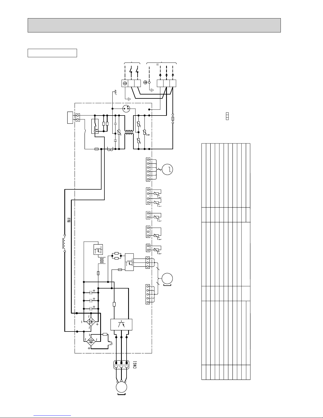
SUZ-KA50VA.TH SUZ-KA50VA1.TH
SUZ-KA60VA.TH SUZ-KA60VA
1.TH
R64B
YLW
230V~
12-24V
CN912
CN663
WHT
BLU
NOISE
FILTER
P.C.BOARD
BRN
TO INDOOR
UNIT
CONNECTING
RED
S3
RT65
21
CN61
13
GRN/YLW
5
PFC
GRN
LD9
POWER
BOARD
RT64
21
CN3
RED
WHT
RS2
RS1
R64A
RS3
RS4
F801
CN901
NR64
ELECTRONIC
CONTROL
P.C.BOARD
CB1
CB2
CB3
HC930
IPM
NF
BLK
BLK
BLK
BLK
WHT
RED
YLW
BLU
ORN
PNK
GRY
BLU
WHT
GRN
GRN
BLU
BLU
BLK
BLK
BLK
BLK
BLK
BLK
BLK
BLK
BLK
BLK
BLK
RED
BLU
L
CT2
CT1
SSR61
U
6
CN7954123 78
CN661
W
CN4
TB2
S1
1
CN601
3
S2
1567
CN702
5321
CN781
13
CN701
12
12
CN931
LD1LD2
T801
R937A
R937B
CN801
231 34512
MF
CN932
3X64
5123
LDE2
12
CT61
TAB 1
F64
F911
LDE1
21S4
POWER SUPPLY
~/N 230V 50Hz
TAB 2
N
PE
L
TB1
CIRCUIT
BREAKER
4
1
RED
YLW
3
2
RED
S
R
21
CN903
21
CN902
21
CN5
6543 1
CN2
27
TAB 4
V
MC
W
U
V
WHT
RT61 RT62 RT68
LEV
OUTDOOR UNIT
:Terminal block :Connector
3. Symbols below indicate.
2. Use copper conductors only (for field wiring).
diagram for servicing.
refer to the indoor unit electric wiring
1. About the indoor side electric wiring,NOTES:
SYMBOL
NAME
SYMBOL
NAME
CURRENT TRANSFORMER
FUSE (T1AL 250V)
LEV
EXPANSION VALVE COIL
L
REACTOR
IPM
INTELLIGENT POWER MODULE
CT61
FUSE (T2AL 250V)
F64
CT1, 2
CURRENT TRANSFORMER
HC930
INTELLIGENT POWER MODULE
F911
F801
FUSE (T3.15AL 250V)
SMOOTHING CAPACITOR
CB1~3
OUTDOOR FAN MOTOR
POWER FACTOR CONTROLLER
NOISE FILTER
RT61
DISCHARGE TEMPERATURE THERMISTOR
RS1~4
RESISTOR
R937A, B
RESISTOR
MF
MC
COMPRESSOR
R64A,B
RESISTOR
PFC
NF
NR64
VAR IST OR
AMBIENT TEMPERATURE THERMISTOR
SOLENOID COIL RELAY
21S4
REVERSING VALVE COIL
X64
RELAY
TB1
TERMINAL BLOCK
TB2
TERMINAL BLOCK
RT65
FIN TEMPERATURE THERMISTOR
RT64
T801
TRANSFORMER
SSR61
RT68
OUTDOOR HEAT EXCHANGER
TEMPERATURE THERMISTOR
DEFROST THERMISTOR
RT62
NAME
SYMBOL
OC322G
20
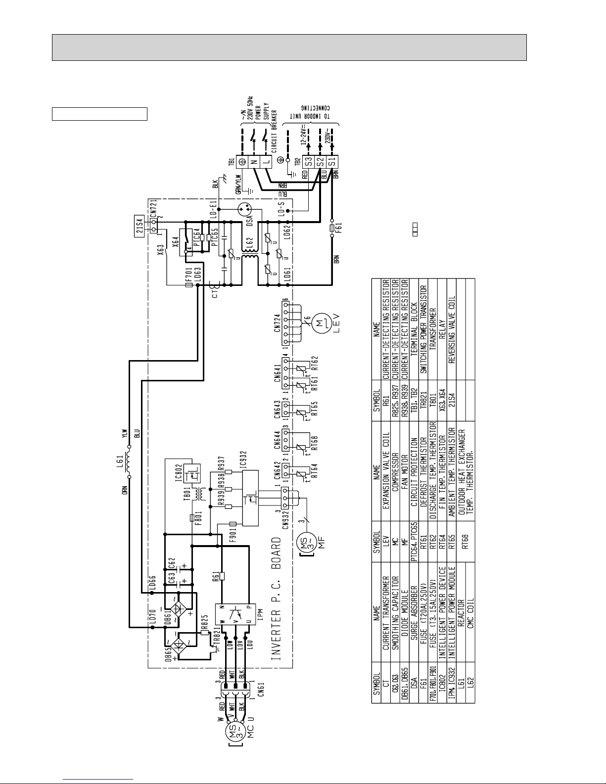
SUZ-KA50VAR2.TH
POWER SUPPLY
~/N 230V 50Hz
CIRCUIT
BREAKER
TO INDOOR
UNIT
CONNECTING
230V~
12-24V
S3S1S2
TB2
BRN
BLU
RED
L
N
GRN/YLW
TB1
BLK
BRN
BLU
F61
BRN
LD-E1
LD-S
LD62
LD61
L62
DSA
PTC65
PTC64
LD63
CT
F701
X64
U
U
U
6
14
12
1
3
12
1
1
3
5
1
3
5
CN724
CN641CN643CN644CN642
RT62
RT61RT65
RT68
RT64
CN932
CN931
MS
3~
INVERTER P.C. BOARD
HC930
R937B
F901
R937A
IC802
T801
F801
C61
C62C63
R61
LD66LD70
DB61
DB65
R825
TR821
IPM
LDU
LDV
LDW
N
P
U
V
W
1
1
3
3
BLKBLK
WHT
RED
WHT
RED
MS
3~
MC
U
V
W
ORN YLW
L61
X63
1 2
CN721
21S4
M
LEV
6
2. Use copper conductors only (for field wiring).
diagram for servicing.
refer to the indoor unit electric wiring
1. About the indoor side electric wiring,NOTES:
SYMBOL
NAME
SYMBOL
NAME
SMOOTHING CAPACITOR
FUSE (T20AL 250V)
LEV
EXPANSION VALVE COIL
L61
REACTOR
HC930,IPM
INTELLIGENT POWER DEVICE
C61,62,63
DIODE MODULE
DB61,DB65
CT
CURRENT TRANSFORMER
F701,F801,F901
INTELLIGENT POWER MODULE
F61
DSA
SURGE ABSORBER
FAN MOTOR
CIRCUIT PROTECTION
RT61
DISCHARGE TEMP. THERMISTOR
R937A, B
MF
MC
COMPRESSOR
R825
PTC64,PTC65
R61
CURRENT-DETECTING RESISTOR
AMBIENT TEMP. THERMISTOR
SWITCHING POWER TRANSISTOR
21S4
REVERSING VALVE COIL
X63,X64
RELAY
TB1,TB52
TERMINAL BLOCK
RT65
FIN TEMP. THERMISTOR
RT64
T801
TRANSFORMER
TR821
RT68
OUTDOOR HEAT EXCHANGER
TEMP. THERMISTOR
DEFROST THERMISTOR
RT62
NAME
SYMBOL
FUSE (T3.15AL 250V)
IC802
L62
REACTOR
CURRENT-DETECTING RESISTOR
CURRENT-DETECTING RESISTOR
MF
:Terminal block
3. Symbols below indicate.
OUTDOOR UNIT
OC322G
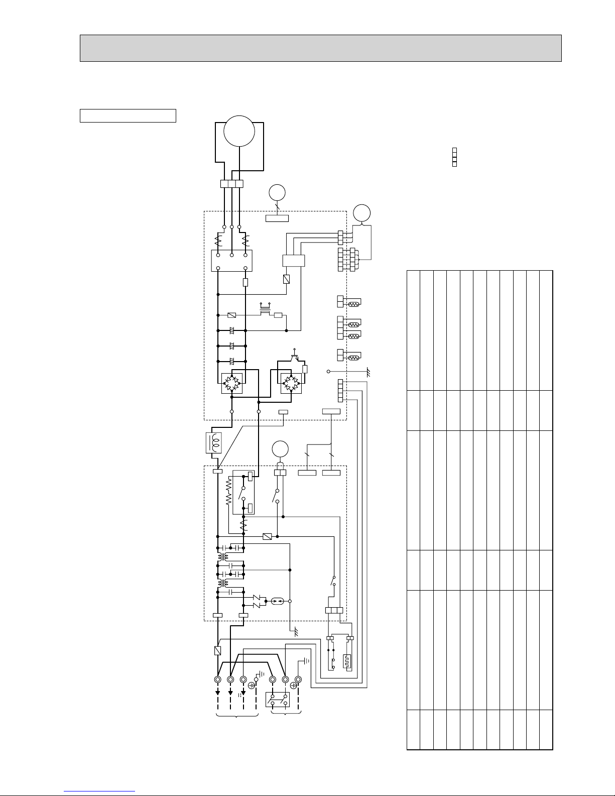
21
SUZ-KA60VAR2.TH
:Terminal block
3. Symbols below indicate.
2. Use copper conductors only (for field wiring).
diagram for servicing.
refer to the indoor unit electric wiring
1. About the indoor side electric wiringNOTES:
SYMBOL
NAME
SYMBOL
NAME
CURRENT TRANSFORMER
FUSE (T1AL 250V)
LEV
EXPANSION VALVE
L
REACTOR
IPM
INTELLIGENT POWER MODULE
CT61
FUSE (T2AL 250V)
F64
CT1, 2
CURRENT TRANSFORMER
HC930
INTELLIGENT POWER MODULE
F911
F801
FUSE (T3.15AL 250V)
SMOOTHING CAPACITOR
CB1~3
FAN MOTOR
POWER FACTOR CONTROLLER
NOISE FILTER
RT61
DISCHARGE TEMP. THERMISTOR
RS1~4
RESISTOR
R937A, B
RESISTOR
MF
MC
COMPRESSOR
R64A,B
RESISTOR
PFC
NF
NR64
VAR IST OR
AMBIENT TEMP. THERMISTOR
SOLENOID COIL RELAY
21S4
REVERSING VALVE COIL
X64
RELAY
TB1
TERMINAL BLOCK
TB2
TERMINAL BLOCK
RT65
FIN TEMP. THERMISTOR
RT64
T801
TRANSFORMER
SSR61
RT68
OUTDOOR HEAT EXCHANGER TEMP. THERMISTOR
DEFROST THERMISTOR
RT62
NAME
SYMBOL
HPS
HIGH PRESSURE SWITCH
OUTDOOR UNIT
OC322G
22
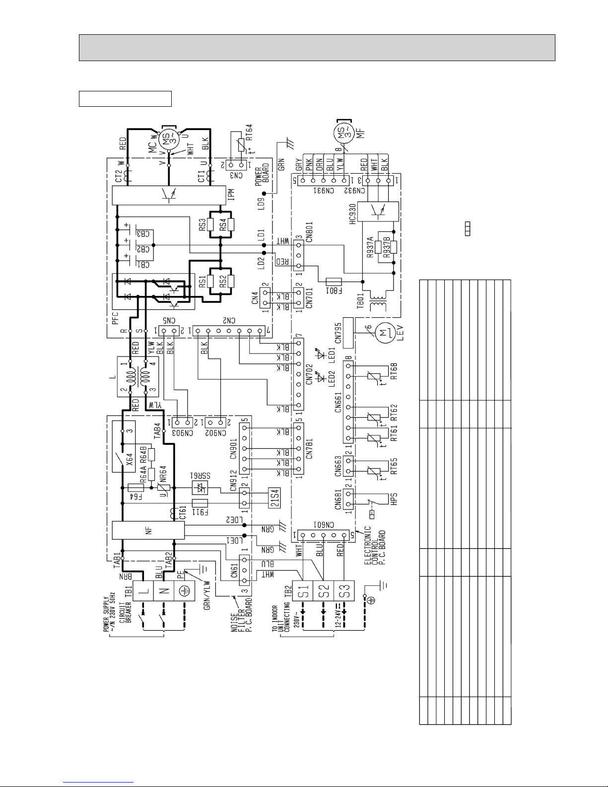
SUZ-KA71VA.TH SUZ-KA71VA1.TH
BLK
CN902
12
CN903
12
TAB4
X64 3
R64A R64B
RED
2
3
1
4
L
YLW
YLW
RED
230V~
12-24V
CN912
CN663
WHT
BLU
NOISE
FILTER
P.C.BOARD
BRN
TO INDOOR
UNIT
CONNECTING
RED
S3
RT65
21
CN61
13
GRN/YLW
5
PFC
GRN
LD9
POWER
BOARD
RT64
21
CN3
HPS
RED
RED
RED
WHT
RS2
RS1 RS3
RS4
F801
CN901
NR64
CN681
ELECTRONIC
CONTROL
P.C.BOARD
CB1
CB2
CB3
HC930
IPM
NF
BLK
BLK
BLK
BLK
WHT
RED
YLW
BLU
ORN
PNK
GRY
BLU
WHT
GRN
GRN
BLU
BLU
BLK
BLK
BLK
BLK
BLK
BLK
BLK
BLK
BLK
BLK
RED
BLU
CT2
CT1
SSR61
U
6
CN7954123 78
CN661
12
W
CN4
TB2
S1
1
CN601
3
S2
1567
CN702
5321
CN781
13
CN701
12
12
CN931
LD1LD2
T801
R937A
R937B
CN801
23134512
MF
CN932
5123
LDE2
12
CT61
TAB1
F64
F911
LDE1
21S4
POWER SUPPLY
~/N 230V 50Hz
TAB 2
N
PE
L
TB1
CIRCUIT
BREAKER
S
R
21
CN5
6543 1
CN2
27
V
MC
W
U
V
WHT
RT61 RT62 RT68
LEV
OUTDOOR UNIT
:Terminal block :Connector
3. Symbols below indicate.
2. Use copper conductors only (for field wiring).
diagram for servicing.
refer to the indoor unit electric wiring
1. About the indoor side electric wiring,NOTES:
SYMBOL
NAME
SYMBOL
NAME
CURRENT TRANSFORMER
FUSE (T1AL 250V)
LEV
EXPANSION VALVE COIL
L
REACTOR
IPM
INTELLIGENT POWER MODULE
HPS
HIGH PRESSURE SWITCH
CT61
CT1, 2
CURRENT TRANSFORMER
HC930
INTELLIGENT POWER MODULE
F911
F801
FUSE (T3.15AL 250V)
F64
FUSE (T2AL 250V)
SMOOTHING CAPACITORCB1~3
OUTDOOR FAN MOTOR
POWER FACTOR CONTROLLER
NOISE FILTER
RT61
DISCHARGE TEMPERATURE THERMISTOR
RS1~4
RESISTOR
R937A, B
RESISTOR
MF
MC
COMPRESSOR
R64A,B RESISTOR
PFC
NF
NR64
VAR IST OR
FIN TEMPERATURE THERMISTOR
SOLENOID COIL RELAY
21S4
REVERSING VALVE COIL
X64
RELAY
TB1
TERMINAL BLOCK
TB2
TERMINAL BLOCK
RT64
T801
TRANSFORMER
SSR61
AMBIENT TEMPERATURE THERMISTOR
RT65
RT68
OUTDOOR HEAT EXCHANGER
TEMPERATURE THERMISTOR
DEFROST THERMISTOR
RT62
NAME
SYMBOL
OC322G
2323
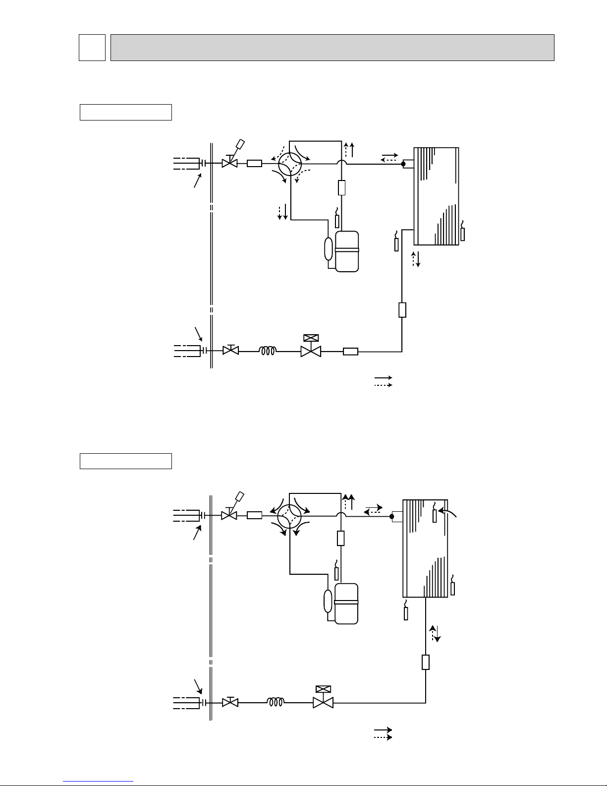
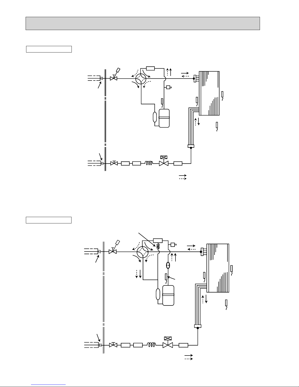
REFRIGERANT SYSTEM DIAGRAM
8
OUTDOOR UNIT
Unit: mm
SUZ-KA25VA.TH
SUZ-KA25VAH.TH
Unit: mm
Outdoor
heat
exchanger
Flared connection
Defrost
thermistor
RT61
Discharge
temperature
thermistor
RT62
Flared connection
Stop valve
(with strainer)
Stop valve
(with service port)
Capillary tube
:3.0×:2.0×240
Refrigerant flow in cooling
Compressor
4-way valve
Refrigerant flow in heating
Refrigerant pipe :9.52
(with heat insulator)
Refrigerant pipe :6.35
(with heat insulator)
LEV
R.V. coil
heating ON
cooling OFF
Strainer
#100
Muffler
Muffler
Ambient
temperature
thermistor
RT65
Muffler
OUTDOOR UNIT
SUZ-KA25VAR1.TH
SUZ-KA25VAHR1.TH
Flared connection
Defrost
thermistor
RT61
Discharge
temperature
thermistor
RT62
Flared connection
Stop valve
(with strainer)
Stop valve
(with service port)
Refrigerant flow in cooling
Compressor
4-way valve
Refrigerant flow in heating
Refrigerant pipe ø9.52
(with heat insulator)
Refrigerant pipe ø6.35
(with heat insulator)
R.V. coil
heating ON
cooling OFF
Strainer
#100
Ambient
temperature
thermistor
RT65
Muffler
Capillary tube
ø3.0×ø2.0×240
Outdoor heat
exchanger
temperature
thermistor
RT68
Muffler
Outdoor
heat
exchanger
LEV
OC322G
24
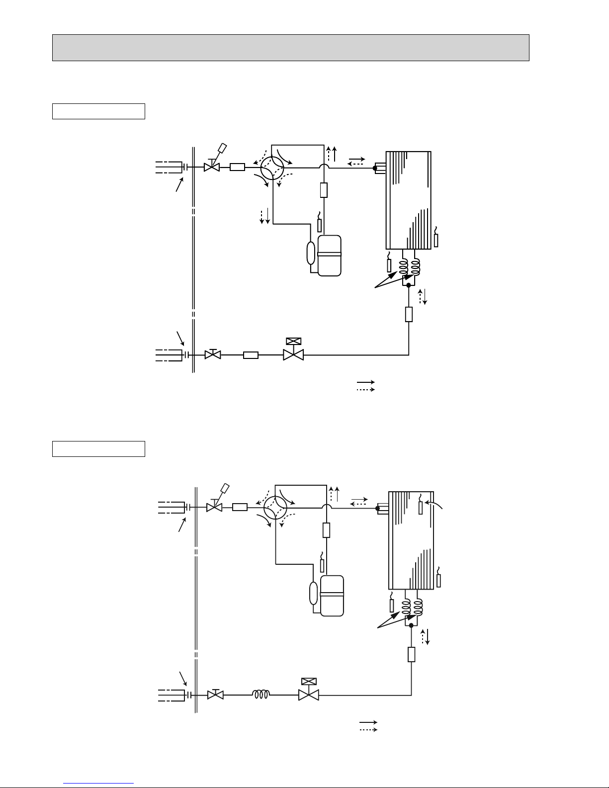
OUTDOOR UNIT
SUZ-KA35VAR1.TH
SUZ-KA35VAHR1.TH
Unit: mm
Unit: mm
Outdoor
heat
exchanger
Flared connection
Defrost
thermistor
RT61
Discharge
temperature
thermistor
RT62
Flared connection
Stop valve
(with strainer)
Stop valve
(with service port)
Refrigerant flow in cooling
Compressor
4-way valve
Refrigerant flow in heating
Refrigerant pipe ø9.52
(with heat insulator)
Refrigerant pipe ø6.35
(with heat insulator)
R.V. coil
heating ON
cooling OFF
Strainer
#100
Capillary tube
ø3.0×ø1.8×600(×2)
LEV
Ambient
temperature
thermistor
Muffler
Capillary tube
ø3.0×ø2.0×240
Outdoor heat
exchanger
temperature
thermistor
Muffler
RT65
RT68
Outdoor
heat
exchanger
Flared connection
Defrost
thermistor
RT61
Discharge
temperature
thermistor
RT62
Flared connection
Stop valve
(with strainer)
Stop valve
(with service port)
Refrigerant flow in cooling
Compressor
4-way valve
Refrigerant flow in heating
Refrigerant pipe :9.52
(with heat insulator)
Refrigerant pipe :6.35
(with heat insulator)
R.V. coil
heating ON
cooling OFF
Strainer
#100
Capillary tube
:3.0×:1.8×600(×2)
LEV
Ambient
temperature
thermistor
RT65
Muffler
Muffler
Muffler
OUTDOOR UNIT
SUZ-KA35VA.TH
SUZ-KA35VAH.TH
OC322G
25
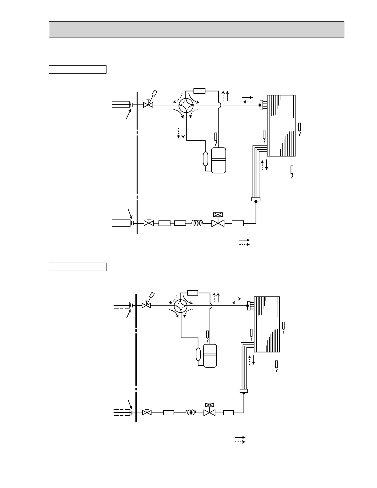
SUZ-KA50VA.TH SUZ-KA50VA1.TH
SUZ-KA60VA.TH SUZ-KA60VA
1.TH
OUTDOOR UNIT
Unit: mm
Outdoor
heat
exchanger
Flared connection
Defrost
thermistor
RT61
Discharge
temperature
thermistor
RT62
Flared connection
Stop valve
Stop valve
(with service port)
Capillary tube
:3.6
×:2.4×50
Refrigerant flow in cooling
Compressor
4-way valve
Refrigerant flow in heating
Refrigerant pipe :12.7 (SUZ-KA50VA)
(with heat insulator) :15.88 (SUZ-KA60VA)
Refrigerant pipe :6.35
(with heat insulator)
LEV
R.V. coil
heating ON
cooling OFF
Muffler
#100
Strainer
#100
Receiver
Outdoor heat
exchanger
temperature
thermistor
RT68
Ambient
temperature
thermistor
RT65
Strainer
#100
Unit: mm
SUZ-KA50VAR2.TH
Outdoor
heat
exchanger
Flared connection
Defrost
thermistor
RT61
Discharge
temperature
thermistor
RT62
Flared connection
Stop valve
(with strainer)
Stop valve
(with service port)
Capillary tube
ø3.6×ø2.4×50
Compressor
4-way valve
Refrigerant pipe ø12.7
(with heat insulator)
Refrigerant pipe ø6.35
(with heat insulator)
LEV
Muffler
#100
Receiver
Outdoor heat
exchanger
temperature
thermistor
RT68
Ambient
temperature
thermistor
RT65
Strainer
#100
Refrigerant flow in cooling
Refrigerant flow in heating
R.V. coil
heating ON
cooling OFF
OUTDOOR UNIT
OC322G
26
SUZ-KA71VA.TH SUZ-KA71VA1.TH
OUTDOOR UNIT
Outdoor
heat
exchanger
Flared connection
Defrost
thermistor
RT61
Discharge
temperature
thermistor
RT62
Flared connection
Stop valve
Stop valve
(with service port)
Capillary tube
:3.6×:2.4×50
Capillary tube
:1.8
×:0.6×1000
Refrigerant flow in cooling
Compressor
4-way valve
Refrigerant flow in heating
Refrigerant pipe :15.88
(with heat insulator)
Refrigerant pipe :9.52
(with heat insulator)
LEV
R.V. coil
heating ON
cooling OFF
Oil separator
High-pressure
switch
Strainer
#100
Receiver
Outdoor
heat
exchanger
temperature
thermistor
RT68
Strainer
#100
Strainer
#100
Ambient
temperature
thermistor
RT65
Unit:mm
Unit:mm
SUZ-KA60VAR2.TH
Outdoor
heat
exchanger
Flared connection
Defrost
thermistor
RT61
Discharge
temperature
thermistor
RT62
Flared connection
Stop valve
Stop valve
(with service port)
Capillary tube
:3.6:2.450
Refrigerant flow in cooling
Compressor
4-way valve
Refrigerant flow in heating
Refrigerant pipe :15.88
(with heat insulator)
Refrigerant pipe :6.35
(with heat insulator)
LEV
R.V. coil
heating ON
cooling OFF
Muffler
#100
Strainer
#100
Receiver
Outdoor heat
exchanger
temperature
thermistor
RT68
Ambient
temperature
thermistor
RT65
Strainer
#100
High-pressure
switch
OUTDOOR UNIT
OC322G
27
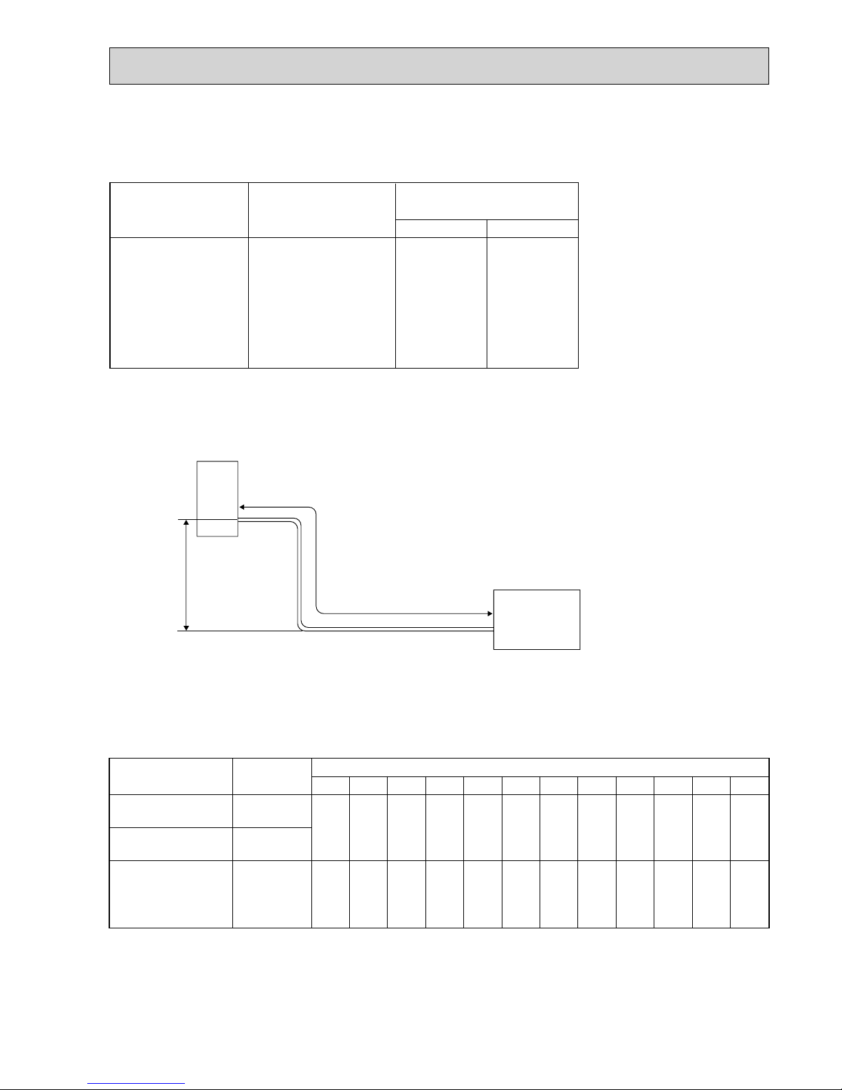
ADDITIONAL REFRIGERANT CHARGE (R410A: g)
Outdoor unit
precharged
900
800
1,050
14m
270
270
7m
0
0
6m
0
0
5m
0
0
11m
180
180
Models
Refrigerant piping length (one way)
Calculation : Xg=30g/m%(Refrigerant piping length(m) - 5)
8m
90
90
9m
120
120
10m
150
150
12m
210
210
13m
240
240
15m
300
300
20m
450
450
SUZ-KA25VA.TH
SUZ-KA25VAH.TH
SUZ-KA35VA.TH
SUZ-KA35VAH.TH
SUZ-KA35VAR1.TH
SUZ-KA35VAHR1.TH
SUZ-KA25VAR1.TH
SUZ-KA25VAHR1.TH
Refrigerant Piping
Max. length
A
+ Height difference should be within 12m regardless of which unit, indoor or outdoor position is high.
+ Max. Height
difference 12m
Indoor
unit
(SLZ/SEZ)
Outdoor unit
MAX. HEIGHT DIFFERENCE
Refrigerant piping
Max. length: m
A
20
Gas
9.52
Liquid
6.35
Piping size O.D: mm
Models
SUZ-KA25VA.TH
SUZ-KA35VA.TH
SUZ-KA25VAH.TH
SUZ-KA35VAH.TH
SUZ-KA25VAR1.TH
SUZ-KA35VAR1.TH
SUZ-KA25VAHR1.TH
SUZ-KA35VAHR1.TH
SUZ-KA25VA.TH SUZ-KA25VAH.TH SUZ-KA25VAR1.TH SUZ-KA25VAHR1.TH
SUZ-KA35VA.TH SUZ-KA35VAH.TH SUZ-KA35VAR1.TH SUZ-KA35VAHR1.TH
MAX. REFRIGERANT PIPING LENGTH
OC322G
28
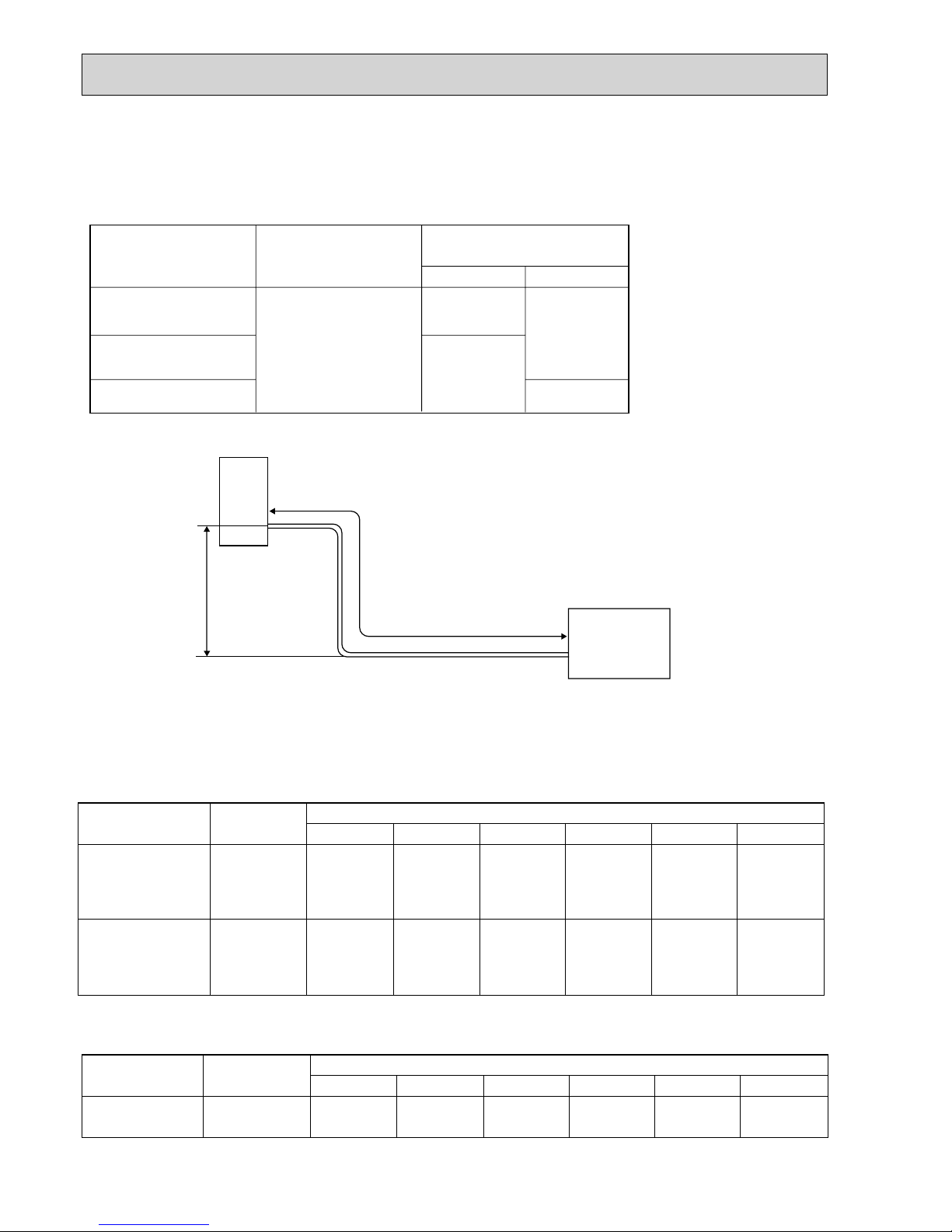
Refrigerant Piping
Max. length
A
+ Height difference should be within 30m regardless of which unit, indoor or outdoor position is high.
Max. Height difference of SUZ-KA50/60/71VA.TH : 15m
SUZ-KA50/60/71VA
1.TH : 30m
SUZ-KA50/60VAR2.TH : 30m
+ Max. Height
difference 30m
Indoor
unit
Outdoor unit
(SLZ/SEZ)
MAX. HEIGHT DIFFERENCE
Refrigerant piping
Max. length: m
A
30
Gas
12.7
15.88
Liquid
6.35
9.52
SUZ-KA50VA.TH
SUZ-KA50VA
1.TH
SUZ-KA50VAR2.TH
SUZ-KA60VA.TH
SUZ-KA60VA
1.TH
SUZ-KA60VAR2.TH
SUZ-KA71VA.TH
SUZ-KA71VA
1.TH
Model
Piping size O.D: mm
Refrigerant piping length (one way)
Outdoor unit
precharged
15m
160
160
20m
260
260
25m
360
360
30m
460
460
7m
0
0
10m
60
60
Model
SUZ-KA50VA.TH
SUZ-KA50VA
1.TH
SUZ-KA50VAR2.TH
SUZ-KA60VA.TH
SUZ-KA60VA
1.TH
SUZ-KA60VAR2.TH
1,600
1,800
ADDITIONAL REFRIGERANT CHARGE (R410A: g)
Calculation : Xg=20g/m o (Refrigerant piping length(m)–7)
SUZ-KA50VA.TH SUZ-KA50VA1.TH SUZ-KA50VAR2.TH
SUZ-KA60VA.TH SUZ-KA60VA
1.TH SUZ-KA60VAR2.TH
SUZ-KA71VA.TH SUZ-KA71VA
1.TH
MAX. REFRIGERANT PIPING LENGTH
Outdoor unit
precharged
2,000
0 165 440 715 990 1,265
Refrigerant piping length (one way)
15m10m7m
Model
SUZ-KA71VA.TH
SUZ-KA71VA
1.TH
20m
25m 30m
Calculation : Xg=55g/m o (Refrigerant piping length(m)-7)
OC322G
2929
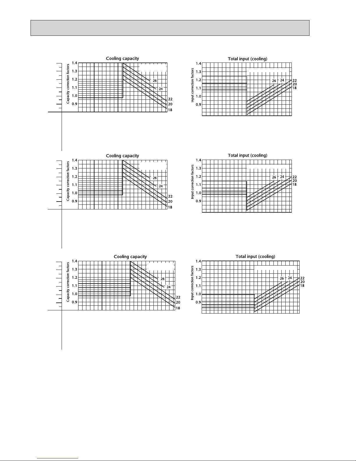
PERFORMANCE CURVES
9
Model
SLZ-KA25VA(L)/SUZ-KA25VA
SLZ-KA35VA(L)/SUZ-KA35VA
SLZ-KA50VA(L)/SUZ-KA50VA
The standard data contained in these specifications applies only to the operation of the air conditioner under normal condition.
Operating conditions vary according to the areas where these units are installed. The following information has been provided
to clarify the operating characteristics of the air conditioner under the conditions indicated by the performance curve.
(1) GUARANTEED VOLTAGE
Rated voltage: ±10% (207~253V), 50Hz
(2) AIR FLOW
Air flow should be set at MAX.
(3) MAIN READINGS
COOLING HEATING
(1) Indoor intake air wet-bulb temperature: W.B. ˚C (1) Indoor intake air dry-bulb temperature: D.B. ˚C
(2) Indoor outlet air wet-bulb temperature: W.B. ˚C (2) Indoor outlet air dry-bulb temperature: D.B. ˚C
(3) Outdoor intake air dry-bulb temperature: D.B. ˚C (3) Outdoor intake air wet-bulb temperature: W.B. ˚C
(4) Total input: W (4) Total input: W
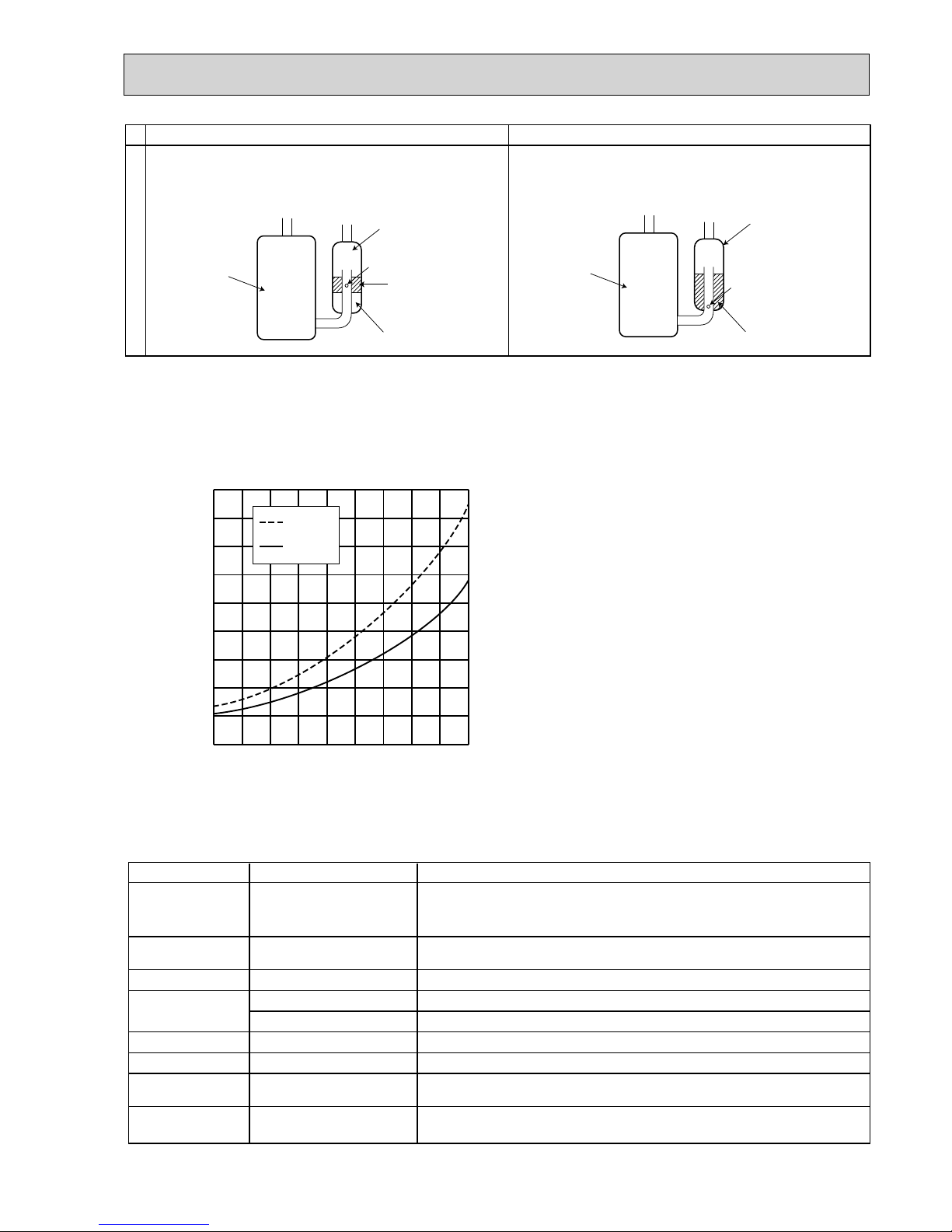
Indoor air wet/dry-bulb temperature difference on the side of the chart on page shows the difference between the
indoor intake air wet/dry-bulb temperature and the indoor outlet air wet/dry-bulb temperature for your reference at service.
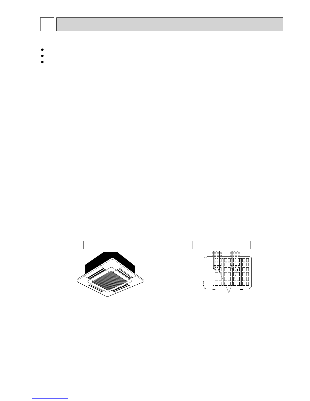
How to measure the indoor air wet-bulb/dry-bulb temperature difference
1. Attach at least 2 sets of wet-and-dry-bulb thermometers to the indoor air inlet as shown in the figure, and at least 2 sets of
wet-and-dry-bulb thermometers to the indoor air outlet. The thermometers must be attached to the position where air speed
is high.
2. Attach at least 2 sets of wet-and-dry-bulb thermometers to the outdoor air inlet.
Cover the thermometers to prevent direct rays of the sun.
3. Check that the air filter is cleaned.
4. Open windows and doors of the room.
5. Press the EMERGENCY OPERATION switch once to start the EMERGENCY COOL (HEAT) MODE.
6. When system stabilizes after more than 15 minutes, measure temperature and take an average temperature.
7. 10 minutes later, measure temperature again and check that the temperature does not change.
Wet-and dry-bulb
thermometers
BACK VIEW
INDOOR UNIT
OUTDOOR UNIT
OC322G
30
Indoor air Wet-bulb temperature
difference (degree)
10.8
10.0
9.2
8.5
7.7
6.9
SUZ-KA50VA
at Rated frequency
Outdoor intake air Dry-bulb temperature ()
-10-15 -5 0 5 101520253035404546
Outdoor intake air Dry-bulb temperature ()
Indoor intake air Wet-bulb temperature(
)
-15 -10 -5 0 5 10 15 20 25 30 35 40 4546
Indoor air Wet-bulb temperature
difference (degree)
8.4
7.8
7.2
6.6
6.0
5.4
SUZ-KA35VA(H)
at Rated frequency
Outdoor intake air Dry-bulb temperature ()
-10-5 0 5 101520253035404546
Outdoor intake air Dry-bulb temperature ()
Indoor intake air Wet-bulb temperature(
)
-10-5 0 5 101520253035404546
Indoor air Wet-bulb temperature
difference (degree)
SUZ-KA25VA(H)
6.4
5.9
5.4
5.0
4.5
4.1
at Rated frequency
Outdoor intake air Dry-bulb temperature () Outdoor intake air Dry-bulb temperature ()
Indoor intake air Wet-bulb temperature(
)
Indoor intake air Wet-bulb
temperature()
Indoor intake air Wet-bulb
temperature()
Indoor intake air Wet-bulb
temperature()
-10-5 0 5 101520253035404546
-10-5 0 5 101520253035404546
OC322G
 Loading...