

Mitsubishi Electric SUZ-KA09, SUZ-KA12, SUZ-KA15, SUZ-KA18NA, SUZ-KA09NA Installation Manual
...Page 1

POUR L’INSTALLATEUR
PARA EL INSTALADOR
FOR INSTALLER
Air-Conditioners
SUZ-KA09, KA12, KA15, KA18NA
INSTALLATION MANUAL
For safe and correct use, read this manual and the indoor unit installation manual thoroughly before installing
the air-conditioner unit.
MANUEL D’INSTALLATION
Avant d’installer le climatiseur, lire attentivement ce manuel, ainsi que le manuel d’installation de l’appareil
intérieur pour une utilisation sûre et correcte.
MANUAL DE INSTALACIÓN
Para un uso correcto y seguro, lea detalladamente este manual y el manual de instalación de la unidad interior
antes de instalar la unidad de aire acondicionado.
Français
Español
English
Page 2
2
Contents
1. The following should always be observed for safety . . . . . . . . . . . . . . . . . . . . 2
2. Selecting the installation location
. . . . . . . . . . . . . . . . . . . . . . . . . . . . . . . . . . . 3
3. Installation diagram
. . . . . . . . . . . . . . . . . . . . . . . . . . . . . . . . . . . . . . . . . . . . . 3
4. Refrigerant piping work
. . . . . . . . . . . . . . . . . . . . . . . . . . . . . . . . . . . . . . . . . . 4
5. Electrical work
. . . . . . . . . . . . . . . . . . . . . . . . . . . . . . . . . . . . . . . . . . . . . . . . . 6
6. Maintenance
. . . . . . . . . . . . . . . . . . . . . . . . . . . . . . . . . . . . . . . . . . . . . . . . . . 7
1. The following should always be observed for safety
Caution:
Could lead to serious injury when operated incorrectly.
• After reading this manual, be sure to keep it together with the instruction
manual in a handy place on the customer’s site.
: Indicates a part which must be grounded.
Warning:
Carefully read the labels afxed to the main unit.
Warning:
■ Do not install the unit by yourself (user).
Improper or incomplete installation could cause re, electric shock, injury due to
the unit falling, or water leakage. Consult a qualied installer or the dealer from
whom you purchased the unit.
■ Follow the instructions detailed in the installation manual.
Incomplete installation could cause re or electric shock, injury due to the unit
falling, or leakage of water.
■ Install the unit securely in a place that can bear the weight of the unit.
If the installation location cannot bear the weight of the unit, the unit could fall
causing injury.
■ Perform electrical work according to the installation manual and be sure to
use an exclusive circuit. Do not connect other electrical appliances to the
circuit.
If the capacity of the power circuit is insufcient or there is incomplete electrical
work, it could result in a re or an electric shock.
■ Ground the unit correctly.
Do not connect the ground wire to a gas pipe, water pipe, lightning rod or telephone ground. Defective grounding could cause electric shock.
■ Do not damage the wires.
Damaged wires could cause re.
■ Be sure to shut off the main power when setting up the indoor P.C. board
or wiring.
Failure to do so could cause electric shock.
■ Use the specied wires to securely connect the indoor and outdoor units.
Attach the wires rmly to avoid applying stress to the terminal block.
Improper connection could cause re.
■ Do not install the unit in a place where ammable gas may leak.
If gas leaks and accumulates around the unit, it could cause an explosion.
■ Do not use intermediate connection of the power cord or the extension
cord. Do not connect many devices to one AC outlet.
It could cause a re or an electric shock.
■ Use the parts provided or specied parts for the installation work.
The use of defective parts could cause an injury or leakage of water due to a
re, an electric shock, the unit falling, etc.
■ Securely attach the electrical cover to the indoor unit and the service panel
to the outdoor unit.
If the electrical cover of the indoor unit and/or the service panel of the outdoor
unit are not attached securely, dust, water, etc. could collect in the unit and could
cause a re or an electric shock.
■ When installing or relocating the unit, make sure that no substance other
than the specied refrigerant (R410A) enters the refrigerant circuit.
Any foreign substances in the refrigerant circuit can cause abnormal pressure
rise or an explosion.
■ Do not discharge the refrigerant into the atmosphere. Check that the refrig-
erant gas does not leak after installation has been completed. If refrigerant
leaks during installation, ventilate the room.
If refrigerant comes in contact with a re, harmful gas could be generated.
If refrigerant gas leaks indoors, and comes into contact with the ame of a fan
heater, space heater, stove, etc., harmful gases will be generated.
■ Use appropriate tools and piping materials for installation.
The pressure of R410A is 1.6 times higher than R22. Not using the appropriate
tools and materials, or improper installation could cause the pipes to burst caus-
ing an injury.
■ When pumping down the refrigerant, stop the compressor before discon-
necting the refrigerant pipes.
If the refrigerant pipes are disconnected while the compressor is running and the
stop valve is open, air could be drawn in and the pressure in the refrigeration
cycle could become abnormally high, causing the pipes to burst.
■ When installing the unit, securely connect the refrigerant pipes before
starting the compressor.
If the compressor is started before the refrigerant pipes are connected and the
stop valve is open, air could be drawn in and the pressure in the refrigeration
cycle could become abnormally high, causing the pipes to burst.
■ Fasten a are nut with a torque wrench as specied in this manual.
If fastened too tight, a are nut could break and cause refrigerant leakage.
■ Install the unit according to national wiring regulations.
Caution:
■ Depending on the installation area, install a Ground Fault Interrupt (GFI)
circuit breaker.
If the Ground Fault Interrupt (GFI) circuit breaker is not installed, an electric
shock could occur.
■ Perform the drainage/piping work securely according to the installation
manual.
If there is defect in the drainage/piping work, water could drip from the unit, and
damage household items.
• Please provide an exclusive circuit for the air conditioner and do not connect other electrical appliances to it.
• Be sure to read “The following should always be observed for safety” be
-
fore installing the air conditioner.
• Be sure to observe the cautions specied here as they include important
items related to safety.
• The indications and meanings are as follows.
Warning:
Could lead to death or serious injury.
■ Do not touch the air inlet or the aluminum ns of the outdoor unit.
This could cause injury.
■ Do not install the outdoor unit where small animals may live.
If small animals enter the unit and damage its electrical parts, it could cause a
malfunction, smoke emission, or re. Keep the area around the unit clean.
Page 3
3
3. Installation diagram
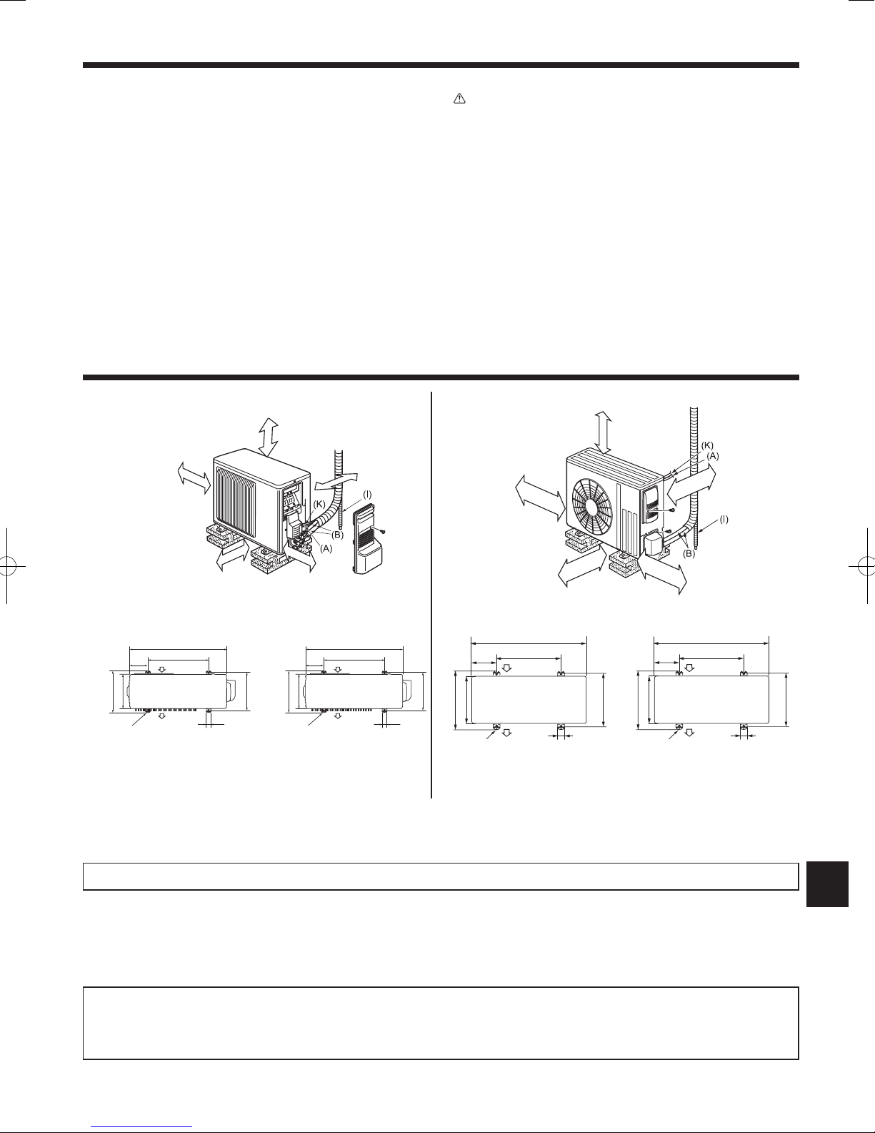
2.1. Outdoor unit
• Where it is not overly exposed to strong winds.
• Where airow is good and dustless.
• Where neighbors are not annoyed by operation sound or hot air.
• Where rigid wall or support is available to prevent the increase of operation sound
or vibration.
• Where there is no risk of combustible gas leakage.
• If installing the unit in a location high above the ground, be sure to secure the unit
legs.
• Where it is at least 10 ft. (3 m) away from the antenna of TV set or radio. Opera
-
tion of the air conditioner may interfere with radio or TV reception in areas where
reception is weak. An amplier may be required for the affected device.
• Install the unit horizontally.
• Please install it in an area not affected by snowfall or blowing snow. In areas with
heavy snow, please install a canopy, a pedestal and/or bafe boards.
Note:
• It is advisable to make a piping loop near outdoor unit so as to reduce vibration.
• For increased efciency, install the outdoor unit in a location where continuous
direct sunlight or excessive water can be avoided as much as possible.
Caution:
When operating the air conditioner in low outside temperature, be sure to follow the
instructions described below.
• Never install the outdoor unit in a place where its air inlet/outlet side may be ex
-
posed directly to wind.
• To prevent exposure to wind, install the outdoor unit with its air inlet side facing
the wall and a bafe board on the air outlet side.
Avoid the following places for installation where air conditioner trouble is liable to
occur.
• Where ammable gas could leak
• Where there is an excessive amount of machine oil in the air.
• Salty places such as the seaside.
• Where sulde gas is generated such as a hot spring.
• Where there is high-frequency or wireless equipment.
The outdoor unit produces condensate during the heating operation. Select the installation place to ensure to prevent the outdoor unit and/or the grounds from being
wet by drain water or damaged by frozen drain water.
2. Selecting the installation location
Open 2 sides of left,
right, or rear side.
4
in.
(100
mm)
or
more
14
in.
(350
mm)
or
more
8
in.
(200
mm)
or
more
Basically open 4 in.
(100 mm) or more
without any obstruction
in front and on both
sides of the unit.
4 in.
(100 mm)
or more
mm:tinUhcni:tinU
31-1/2
19-11/16
Air inlet
Air outlet
13-9/16
11-1/4
2-3/8×13/16 slot
12-12-3/4
1-9/16
800
500
Air inlet
Air outlet
2-10×21 slot
344.5
285
150
40
304-325
515/16
mm:tinUhcni:tinU
33-1/16
14-3/16
19-11/16
Air inlet
6-5/8
15-7/16
13
Air outlet
4-3/8 x 13/16 slot
1-9/16
40
840
169
500
Air
inlet
392
330
360
Air outlet
4-10 x 21 slot
20 in. (500 mm)
or more
4
in.
(100
mm)
or
more
4
in.
(100
mm)
or
more
14
in.
(350
mm)
or
more
20
in.
(500
mm)
or
more
SUZ-KA09, KA12, KA15NA SUZ-KA18NA
When the piping is to be attached to a wall containing metals (tin plated) or metal netting, use a chemically treated wooden piece 25/32 in. (20 mm) or thicker between the
wall and the piping or wrap 7 to 8 turns of insulation vinyl tape around the piping.
Units should be installed by licensed contractor accordingly to local code requirement.
Note:
When operating the air conditioner in low outside temperature, be sure to follow the instructions described below.
• Never install the outdoor unit in a place where its air inlet/outlet side may be exposed directly to wind.
• To prevent exposure to wind, install the outdoor unit with its air inlet side facing the wall.
• To prevent exposure to wind, it is recommended to install a bafe board on the air outlet side of the outdoor unit.
Drain piping for outdoor unit
Install the unit horizontally.
Do not use drain socket in cold regions. Drain may freeze and make the fan stop.
The outdoor unit produces condensate during the heating operation. Select the installation place to ensure to prevent the outdoor unit and/or the grounds from being
wet by drain water or damaged by frozen drain water.
Page 4
4
4. Refrigerant piping work
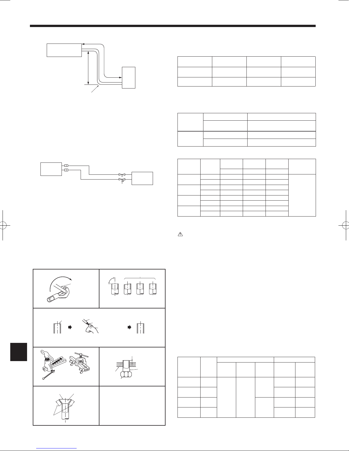
4.1. Refrigerant pipe (Fig. 4-1, Fig. 4-2)
► Check that the difference between the heights of the indoor and outdoor
units, the length of refrigerant pipe, and the number of bends in the pipe
are within the limits shown below.
Models
A Pipe length
(one way)
B Height
difference
C Number of
bends (one way)
SUZ-KA09, KA12,
KA15
Max. 65 ft (20 m) Max. 40 ft (12 m)
Max. 10
SUZ-KA18 Max. 100 ft (30 m) Max. 50 ft (15 m) Max. 10
• Height difference limitations are binding regardless of which unit, indoor or out
-
door, is positioned higher.
• Refrigerant adjustment ... If pipe length exceeds 25 ft. (7.5 m), additional refrig
erant (R410A) charge is required.
(The outdoor unit is charged with refrigerant for pipe length up to 25 ft. (7.5 m).)
Pipe length
Up to 25 ft (7.5 m)
No additional charge is required.
Exceeding 25 ft (7.5 m)
Additional charge is required.
(Refer to the table below.)
Refrigerant to
be added
SUZ-KA09, KA12, KA15 1.62 oz each 5 ft. (30 g/m)
SUZ-KA18 1.08 oz each 5 ft. (20 g/m)
• Table below shows the specications of pipes commercially available.
Model Pipe
Outside
diameter
Min. wall
thickness
Insulation
thickness
Insulation
material
inch (mm) inch (mm) inch (mm)
SUZ-KA09
For liquid 1/4 (6.35) 0.0315 (0.8) 5/16 (8)
Heat resisting
foam plastic
0.045 specic
gravity
For gas 3/8 (9.52) 0.0315 (0.8) 5/16 (8)
SUZ-KA12
For liquid 1/4 (6.35) 0.0315 (0.8) 5/16 (8)
For gas 3/8 (9.52) 0.0315 (0.8) 5/16 (8)
SUZ-KA15
For liquid 1/4 (6.35) 0.0315 (0.8) 5/16 (8)
For gas 1/2 (12.7) 0.0315 (0.8) 5/16 (8)
SUZ-KA18
For liquid 1/4 (6.35) 0.0315 (0.8) 5/16 (8)
For gas 1/2 (12.7) 0.0315 (0.8) 5/16 (8)
• To prevent condensation, insulate the 2 refrigerant pipes.
• Refrigerant pipe bending radius must be 4 in. (100 mm) or more
Caution:
Be sure to use the insulation of specied thickness (table on the above). Excessive
insulation may cause incorrect installation of the indoor unit, and too little insulation
may cause condensate to form.
• The unit has ared connections on both indoor and outdoor sides.
• Remove the valve cover from the outdoor unit, then connect the pipe.
• Refrigerant pipes are used to connect the indoor and outdoor units.
• Be careful not to crush or over bend the pipe in pipe bending.
ø1/4 (6.35)
ø3/8 (9.52)
ø3/8 (9.52)
ø1/2 (12.7)
Fig. 4-1
Fig. 4-2
D Indoor unit
E Outdoor unit
A Indoor unit
B Outdoor unit
4.2. Flaring work (Fig. 4-3)
1) Cut the cooper pipe as straight as possible with a pipe cutter.
2) Remove all burrs from the cut section of pipe, ensuring that precautions are
taken to avoid getting metal shavings into the piping.
3) Remove are nuts attached to indoor and outdoor units, then put them on pipe.
4) Flaring work. Firmly hold copper pipe in the dimension shown in the table. Select
A inch (mm) from the table according to the tool you use.
5) Check
• Compare the ared work.
•
If are is defective, cut off the section and repeat procedure.
Pipe diameter
inch (mm)
Nut
inch (mm)
A inch (mm) Tightening torque
Clutch
type tool
for R410A
Clutch
type tool
for R22
Wing nut
type tool
for R22
N·m
ft·lb
(kgf·cm)
1/4 (6.35) 1/4 (17)
0 to 0.02
(0 to 0.5)
0.04 to
0.06
(1.0 to 1.5)
0.06 to
0.08
(1.5 to 2.0)
13.7 to 17.7
10 to 13
(140 to 180)
3/8 (9.52) 3/8 (22)
34.3 to 41.2
25 to 30
(350 to 420)
1/2 (12.7) 1/2 (26)
0.08 to
0.10
(2.0 to 2.5)
49.0 to 56.4
36 to 42
(500 to 575)
5/8 (15.88) 5/8 (29)
73.5 to 78.4
54 to 58
(750 to 800)
Copper
pipe
Good
90°
Tilted
No good
Burr
Copper pipe
Spare reamer
Pipe cutter
Smooth all around
Even length
all around
Inside is shin
-
ing
without any
scratches.
A
Flare nut
Die
C
opper pipe
Clutch type
Flaring tool
Wing nut type
Uneven Burred
Fig. 4-3
Page 5
Flare cutting dimensions
45˚± 2˚
90˚± 0.5˚
Flare nut tightening torque
ø
A
R1/64 to R1/32
(inch)
A Liquid pipe
B Gas pipe
C Insulation
D Taping
Fig. 4-5
5
4. Refrigerant piping work
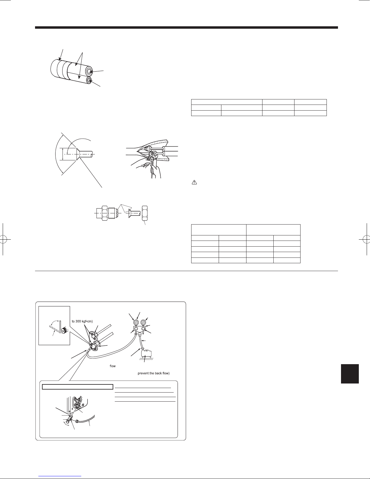
4.3. Connecting pipes (Fig. 4-4, Fig. 4-5)
• Fasten are nut with a torque wrench as specied in the table (refer to 4.2.).
• When fastened too tight, are nut may eventually break and cause refrigerant
leakage.
[Fig. 4-5]
• Apply thin layer of refrigerant oil to pipe and joint seating surface before tightening
are nut. A
• Use 2 wrenches to tighten piping connections.
B
• Use leak detector or soapy water to check for gas leaks after connections are
completed.
• Apply refrigerant oil over the entire are seat surface.
C
• Use the are nuts for the following pipe size. D
KA09, KA12 KA15, KA18
Gas side Pipe size inch (mm) 3/8 (9.52) 1/2 (12.7)
Liquid side Pipe size inch (mm) 1/4 (6.35) 1/4 (6.35)
*1: The are nut is attached to its pipe.
*2: The are nut is in the outdoor unit accessory.
Do not use the are nuts other than the attachment. If it is used, a gas leakage
or even a pipe extraction may occur.
• Refrigerant pipe bending radius must be 4 in. (100 mm) or more.
• Make sure the pipes do not contact the compressor. Abnormal noise or vibration
may result.
1 Pipes must be connected starting from the indoor unit.
Flare nuts must be tightened with a torque wrench.
2 Flare the liquid pipes and gas pipes and apply a thin layer of refrigerant oil
(Applied on site).
Warning:
Be careful of ying are nut. (Internally pressurized)
Remove the are nuts as follows:
1. Loosen the nut until you hear a hissing noise.
2. Do not remove the nut until the gas has been completely released (i.e.,
hissing noise stops)
3.
Check that the gas has been completely released, and then remove the nut.
A (Fig. 4-5)
Pipe diameter
Flare dimensions
øA dimensions
inch (mm) inch (mm)
1/4” (6.35) 11/32 - 23/64 (8.7 - 9.1)
3/8” (9.52) 1/2 - 33/64 (12.8 - 13.2)
1/2” (12.7) 41/64 - 21/32 (16.2 - 16.6)
5/8” (15.88) 49/64 - 25/32 (19.3 - 19.7)
Fig. 4-4
4.4. Purging procedures and leak test
1) Remove service port cap of stop valve on the side of the outdoor unit gas pipe.
2) Connect gauge manifold valve and vacuum pump to service port of stop valve
on the gas pipe side of the outdoor unit.
3) Run the vacuum pump 15 minutes or more.
4) Check the vacuum with the gauge manifold valve, then close it and shut off the
vacuum pump.
5) Leave as it is for one or two minutes. Make sure pointer gauge manifold valve
remains in the same position. Conrm that pressure gauge shows -0.101 MPa
[Gauge] (-30 in.Hg [-760 mmHg]).
6) Quickly remove gauge manifold valve from service port of stop valve.
7) After refrigerant pipes are connected and evacuated, fully open all stop valves
on both sides of gas pipe and liquid pipe. Operating the unit without fully opening
the valves lowers the performance and causes problems.
8) Refer to 4.1. Refrigerant pipe, and charge the prescribed amount of refrigerant if
needed. Be sure to charge slowly with liquid refrigerant. Otherwise, composition
of the refrigerant in the system may be changed and affect performance of the
air conditioner.
9) Tighten cap of service port.
10) Conduct a leak test
Stop valve for
GAS
Stop
valve cap
(Torque 19.6 to
29.4 N•m, 200
Vacuum pump (or the vacuum
pump with the function to
Gauge manifold valve
(for R410A)
Compound pressure gauge
(for R410A)
–0.101 MPa
(–30
in.Hg
[–760 mmHg])
Handle
Low
Handle
High
Adapter for preventing
the back
Charge
hose
(for R410A)
*Close
*Open
Hexagonal
wrench
Precautions when using the control valve
When attaching the control valve
to the service port, valve core may
deform or loosen if excess pressure
is applied. This may cause gas leak.
Service port
Charge hose
Body
Close
Open
Control valve
A
When attaching the control valve to
the service port, make sure that the
valve core is in closed position, and
then tighten part A. Do not tighten
part A or turn the body when valve
core is in open position.
Service port cap
(Torque 13.7 to
17.7 N•m, 140 to
180 kgf•cm)
*4
to 5 turns
Stop valve
for LIQUID
Pressure gauge
(for R410A)
Page 6
6
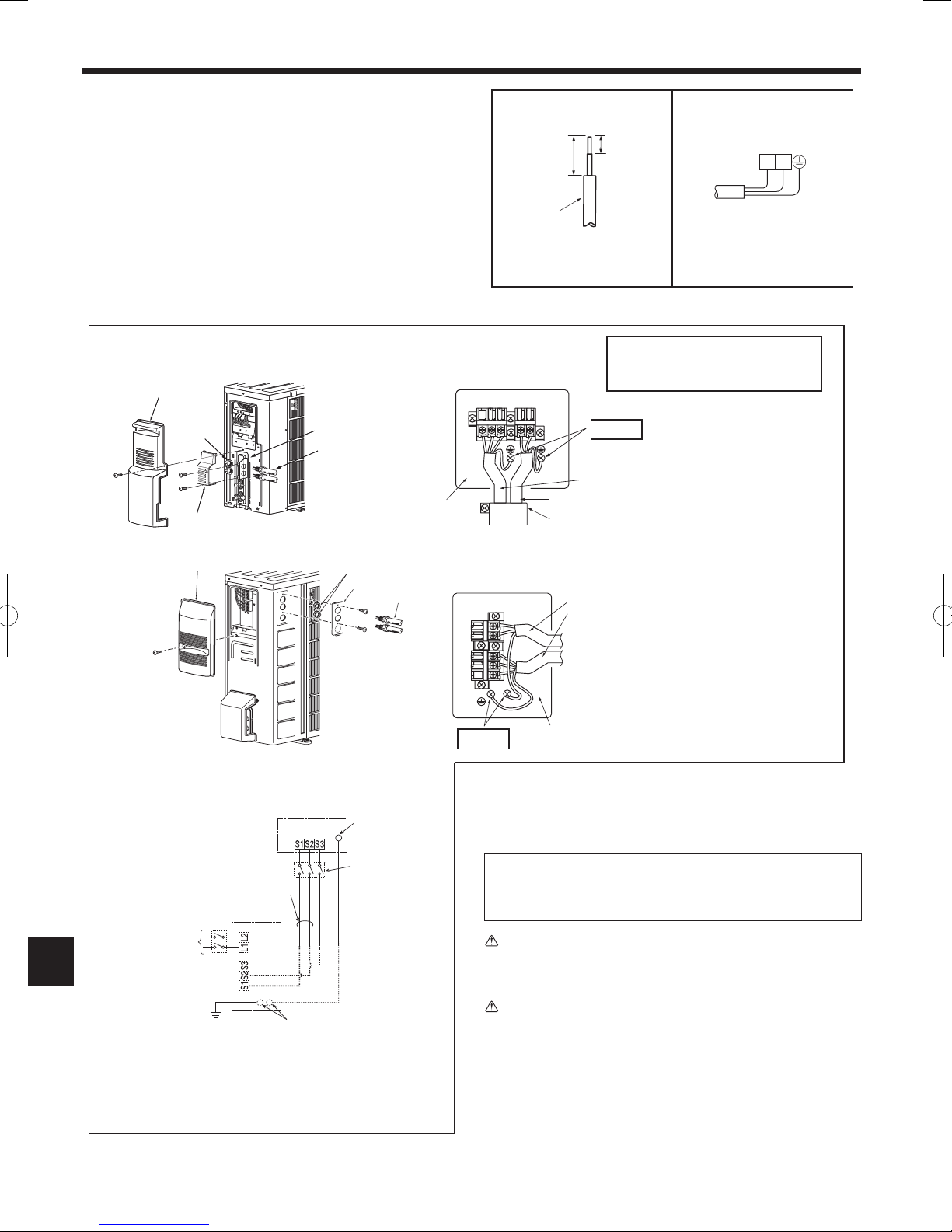
5. Electrical work
5.1. Connecting wires for outdoor unit
1) Remove the service panel.
2) Remove the conduit cover.
3) Attach the conduit connector to conduit plate with lock nut then secure it against
unit with screws.
4) Connect ground wires of indoor/outdoor unit connecting wire (A) and power sup
-
ply cord (K) to the TB support.
5) Loosen the terminal screw, and attach indoor/outdoor unit connecting wire (A)
from the indoor unit correctly on the terminal block. Attach the wire to the terminal block securely so that its core cannot be seen, and no external force affects
the connecting section of the terminal block.
6) Firmly tighten the terminal screws. After tightening, verify that the wires are
tightly fastened.
7) Connect power supply cord (K).
8) Install the conduit cover.
9) Install the service panel securely.
Lead wire
Power supply cord (K)
L1
L2
1-3/8 in.
(35 mm)
19/32 in.
(15
mm)
Terminal block
Conduit cover
Power supply cord (K)
Indoor/outdoor unit
connecting wire (A)
• Make earth wire a little longer than others.
(More than 2-3/8 in. [60 mm])
• For future servicing, leave some slack in
the connecting wires.
Service panel
Lock nut
Conduit cover
Conduit plate
Connector
Grounding
terminal
TB support
Terminal block
to conduit cover
Power supply cord (K)
Indoor/outdoor unit
connecting wire (A)
Service panel
Lock nut
Conduit cover
Connector
TB support
Grounding
terminal
INDOOR UNIT
Terminal block
208/230 V AC
1phase, 60 Hz
Grounding
terminal**
Disconnect
switch*
OUTDOOR UNIT
Grounding
terminal**
Ground
Power supply
208/230 V AC,
1phase 2wires.
60 Hz
Terminal
block 1
Remark:
* A disconnect switch is
required.
Check the local code.
** Use a ring tongue termi
nal in order to connect a
ground wire to terminal.
Terminal block 2
SUZ-KA09, KA12, KA15NA
SUZ-KA18NA
• Connect the cable from the indoor unit correctly on the terminal-block.
• Use the same terminal block and polarity as is used with the indoor unit.
• For aftercare maintenance, give extra length to connecting cable.
• Both ends of connecting cable (extension wire) are peeled off. When too long,
or connected by cutting off the middle, peel off power supply cable to the size
given in the gure.
• Be careful not to contact connecting cable with piping.
Caution:
• Use care not to make miswiring.
• Firmly tighten the terminal screws to prevent them from loosening.
• After tightening, pull the wires lightly to conrm that they do not move.
Warning:
• Be sure to attach the service panel of the indoor unit securely. If it is not
attached correctly, it could result in a re or an electric shock due to dust,
water, etc.
• Tighten terminal screws securely.
• Wiring should be done so that the power lines are not subject to tension.
Otherwise, heat may be generated or re may occur.
Page 7

S1
S2
S3
S1
S2
S3
208/230V
Single phase
Isolator
3 poles isolator
A-Control
Outdoor Unit
A-Control
Indoor Unit
7
5. Electrical work
Warning:
In case of A-control wiring, there is high voltage potential on the S3 terminal caused by electrical circuit design that has no electrical insulation between power
line and communication signal line. Therefore, please turn off the main power supply when servicing. And do not touch the S1, S2, S3 terminals when the power
is energized. If isolator should be used between indoor unit and outdoor unit, please use 3-pole type.
6. Maintenance
5.2. Field electrical wiring
Outdoor unit model SUZ-KA09, KA12, KA15NA SUZ-KA18NA
Power supply ~/N (single), 60 Hz 208/230 V ~/N (single), 60 Hz 208/230 V
Max. Fuse size (time delay) *1 15 A 15 A
Min. Circuit Ampacity 12 A 14 A
Wiring
Wire No. ×
size
Outdoor unit power supply 2 × Min. AWG 14 2 × Min. AWG 14
Outdoor unit power supply earth 1 × Min. AWG 14 1 × Min. AWG 14
Indoor unit-Outdoor unit 3 × AWG 14 (Polar) 3 × AWG 14 (Polar)
Indoor unit-Outdoor unit ground 1 × Min. AWG 16 1 × Min. AWG 16
Circuit
rating
Outdoor unit L1-L2 *2 AC 208/230 V AC 208/230 V
Indoor unit-Outdoor unit S1-S2 *2 AC 208/230 V AC 208/230 V
Indoor unit-Outdoor unit S2-S3 *2 DC 12 V - 24 V (Polar) DC 12 V - 24 V (Polar)
*1. Use ground leakage breaker (NV).
*2. The gures are NOT always against the ground.
S3 terminal has DC24 V against S2 terminal. However between S3 and S1, these terminals are NOT electrically insulated by the transformer or other device.
Notes: 1. Wiring size must comply with the applicable local and national code.
2.
Use copper supply wires.
3. Use wires rated 600V or more for the power supply cables and the indoor/outdoor unit connecting cables.
4. Install an earth longer than other cables.
6.1. Gas charge (Fig. 6-1)
1. Connect gas cylinder to the service port of stop valve (3-way).
2. Execute air purge of the pipe (or hose) coming from refrigerant gas cylinder.
3. Replenish specied amount of refrigerant, while running the air conditioner for
cooling.
Note:
In case of adding refrigerant, comply with the quantity specied for the refrigerating cycle.
Caution:
• Do not discharge the refrigerant into the atmosphere.
Take care not to discharge refrigerant into the atmosphere during installation, reinstallation, or repairs to the refrigerant circuit.
• For additional charging, charge the refrigerant from liquid phase of the gas
cylinder.
If the refrigerant is charged from the gas phase, composition change may
occur in the refrigerant inside the cylinder and the outdoor unit. In this
case, ability of the refrigerating cycle decreases or normal operation can
be impossible. However, charging the liquid refrigerant all at once may
cause the compressor to be locked. Thus, charge the refrigerant slowly.
To maintain the high pressure of the gas cylinder, warm the gas cylinder with warm
water (under 104 °F, 40 °C) during cold season. But never use naked re or steam.
A Indoor unit
B Union
C Liquid pipe
D Gas pipe
E Stop valve
F Outdoor unit
G Refrigerant gas cylinder
operating valve
H Refrigerant gas cylinder for R410A with siphon
I Refrigerant (liquid)
J Electronic scale for refrigerant charging
K Charge hose (for R410A)
L Gauge manifold valve (for R410A)
M Service port
Fig. 6-1
Page 8

8
Index
1. Les mesures de sécurité suivantes doivent toujours être observées
Attention:
Pouvant entraîner des blessures graves si l’unité n’est pas utilisée correctement.
•
Lorsque vous aurez lu le manuel en entier, veuillez le garder dans un endroit
pratique, chez le client, avec le manuel d’utilisation.
:Indique un élément qui doit être mis à la terre.
Avertissement:
Prendre soin de lire les étiquettes se trouvant sur l’appareil principal.
Avertissement:
■ N’installez pas l’unité vous-même (utilisateur).
Une installation incorrecte ou incomplète peut être à l’origine d’un incendie, d’un
choc électrique ou de blessures à la suite de la chute de l’unité ou de fuites d’eau.
Contactez un technicien qualié ou le revendeur à qui vous avez acheté l’unité.
■ Suivez les instructions détaillées dans le manuel d’installation.
Une installation incomplète peut être à l’origine d’un incendie, d’un choc électrique ou de blessures à la suite de la chute de l’unité ou de fuites d’eau.
■
Installez solidement l’unité dans un endroit capable de supporter son poids.
Si l’emplacement d’installation ne peut pas supporter le poids de l’unité, celle-ci
risque de tomber et de provoquer des blessures.
■ Exécutez les travaux électriques selon le manuel d’installation et veillez à
utiliser un circuit unique. Ne branchez pas d’autres appareils électriques
au circuit.
Un circuit électrique d’une capacité insufsante ou des travaux électriques incomplets peuvent être à l’origine d’un incendie ou d’un choc électrique.
■ Raccordez correctement l’unité à la terre.
Ne branchez pas le l de terre à un tuyau de gaz ou d’eau, à un paratonnerre ou
à la ligne de terre téléphonique. Une mise à la terre défectueuse peut entraîner
un choc électrique.
■ Veillez à ne pas endommager les câbles.
Des câbles endommagés peuvent provoquer un incendie.
■ Veillez àtoujourscouper l’alimentation principale lorsdela conguration
de la carte à circuits imprimés interne ou du câblage.
Le non-respect de cette recommandation peut entraîner un choc électrique.
■ Utilisezles câblesspéciéspourraccorderen toutesécuritélesunitésin-
terne et externe. Fixez les câbles solidement pour éviter toute pression sur
le bloc de raccordement.
Un raccordement incorrect peut provoquer un incendie.
■
N’installezpasl’unitédansunendroitexposéàdesfuitesdegazinammable.
La fuite ou l’accumulation de gaz autour de l’unité peut entraîner une explosion.
■
N’utilisez pas de raccord intermédiaire ou de rallonge pour brancher le cordon d’alimentation. Ne branchez pas plusieurs appareils à une prise secteur.
Cela peut provoquer un incendie ou un choc électrique.
■ Utilisez les pièces fournies ou spécifiées lors des travaux d’installation.
L’utilisation de pièces défectueuses peut être à l’origine de blessures ou de fuites d’eau dues à un incendie, un choc électrique, la chute de l’unité, etc.
■ Fixez correctement le couvercle du boîtier électrique de l’unité interne et le
panneau de service de l’unité externe.
Si le couvercle du boîtier électrique de l’unité interne et/ou le panneau de service
de l’unité externe sont mal xés, ils risquent de provoquer un incendie ou un choc
électrique en raison de la poussière, de l’eau, etc. présentes dans le circuit.
■ Lors de l’installation ou du déplacement de l’unité, veillez à ce qu’aucune
autresubstancequeleréfrigérant spécié(R410A) nepénètre dansle cir
-
cuit de réfrigération.
La présence d’une substance étrangère dans le circuit de réfrigération peut pro-
voquer une augmentation anormale de la pression, voire une explosion.
■ Nelibérezpasleréfrigérantdansl’atmosphère.Vériezl’absencedefuites
de gaz réfrigérant une fois l’installation terminée. En cas de fuite de réfrigérant pendant l’installation, aérez la pièce.
Si le réfrigérant entre en contact avec un feu, des substances toxiques peuvent
se dégager. Si le réfrigérant entre en contact avec la flamme d’un appareil de
chauffage à ventilation, chauffage d’appoint, poêle, etc., des substances toxiques peuvent se dégager.
■ Utilisez les outils et l’équipement de tuyauterie adaptés à l’installation.
La pression du réfrigérant R410A est 1,6 fois supérieure à celle du R22. L’utilisation d’outils et d’équipements non adaptés ou une installation incomplète peut
provoquer l’éclatement des tuyaux et blesser quelqu’un.
■ Pendant l’opération d’aspiration du réfrigérant, arrêtez le compresseur
avant de débrancher les tuyaux de réfrigérant.
Si les tuyaux de réfrigérant sont débranchés alors que le compresseur fonctionne et si le robinet d’arrêt est ouvert, de l’air pourrait être aspiré et la pression
du cycle de réfrigération pourrait augmenter de façon anormale, entraînant l’
explosion des tuyaux.
■ Pendant l’installation de l’unité, branchez correctement les tuyaux de réfri-
gérant avant de lancer le compresseur.
Si le compresseur démarre avant le branchement des tuyaux de réfrigérant et si le
robinet d’arrêt est ouvert, de l’air pourrait être aspiré et la pression du cycle de réfrigération pourrait augmenter de façon anormale, entraînant l’explosion des tuyaux.
■ Fixezunécrou évaséavec uneclédynamométrique commespécié dans
ce manuel.
S’il est trop serré, il risque de se rompre et de provoquer une fuite de réfrigérant.
■ Installez l’unité conformément aux normes électriques nationales.
Attention:
■ Installez un disjoncteur de fuites à la terre selon l’endroit d’installation.
Si le disjoncteur de fuites à la terre n’est pas installé, un choc électrique peut se
produire.
■ Réalisez les travaux de vidange/tuyauterie conformément au manuel d’ins-
tallation.
Si les travaux de vidange/tuyauterie ne sont pas réalisés correctement, de l’eau
pourrait s’écouler de l’unité et endommager le mobilier.
• Veuillez prévoir un circuit réservé au climatiseur et ne pas brancher d’
autres appareils électriques sur ce circuit.
• Veuillez lire en entier “Les mesures de sécurité suivantes doivent toujours
être respectées” avant d’installer le climatiseur.
• Comme ces mesures sont très importantes pour votre sécurité, veuillez les
respecter.
• Lessymbolessignient:
Avertissement:
Pouvant entraîner des blessures graves, voire la mort.
■ Ne touchez ni l’entrée d’air ni les ailettes en aluminium de l’unité externe.
Cela peut provoquer des blessures.
■ N’installez pas l’unité externe à proximité de l’habitat de petits animaux.
Si des petits animaux entrent dans l’unité et endommagent ses composants
électriques, ils peuvent provoquer un dysfonctionnement, des émissions de fumée ou un incendie. Nettoyez régulièrement la périphérie de l’unité.
1. Les mesures de sécurité suivantes doivent toujours être observées . . . . . . . 8
2. Choisir l’emplacement de l’installation
. . . . . . . . . . . . . . . . . . . . . . . . . . . . . . . 9
3. Schéma d’installation
. . . . . . . . . . . . . . . . . . . . . . . . . . . . . . . . . . . . . . . . . . . . 9
4. Mise en place des tuyaux de réfrigérant
. . . . . . . . . . . . . . . . . . . . . . . . . . . . 10
5. Installations électriques
. . . . . . . . . . . . . . . . . . . . . . . . . . . . . . . . . . . . . . . . . 12
6. Entretien
. . . . . . . . . . . . . . . . . . . . . . . . . . . . . . . . . . . . . . . . . . . . . . . . . . . . . 13
Page 9

9
3. Schéma d’installation
2.1. Appareil extérieur
• Emplacement à l’abri de vents violents.
• Emplacement favorisant une bonne circulation d’air sans poussière.
• Emplacement ne générant pas de nuisance pour les voisins (bruit de fonctionne
-
ment ou air chaud).
• Emplacement sur un mur ou un support rigide pour éviter l’augmentation du bruit
de fonctionnement ou des vibrations.
• Emplacement qui ne risque pas d’être exposé à des fuites de gaz combustible.
• Lorsque l’unité est placée en hauteur, les pieds doivent être xés.
• Emplacement à une distance de 10 ft. (3 m) minimum de l’antenne TV ou radio.
Le fonctionnement du climatiseur peut interférer avec la réception TV ou radio
dans des zones où la réception est faible. Il peut s’avérer nécessaire de brancher
un amplicateur sur l’appareil concerné.
• Installez l’unité horizontalement.
• Installez l’unité dans un endroit à l’abri du vent et de la neige. Dans les zones
soumises à de fortes chutes de neige, installez un abri, un socle et/ou des écrans
de protection.
Remarque:
• Il est conseillé de faire une boucle avec le tuyau à proximité de l’unité externe
pour réduire les vibrations.
• Pour une meilleure efcacité, installez l’unité externe dans un endroit à l’abri des
rayons directs du soleil et des chutes excessives d’eau.
Attention:
Si vous utilisez le climatiseur alors que la température extérieure est basse, veillez
à observer les instructions ci-dessous.
• N’installez jamais l’unité externe dans un endroit où le côté présentant l’entrée/la
sortie d’air risque d’être directement exposé au vent.
• Pour protéger l’unité externe du vent, installez-la de façon à ce que l’entrée d’air
soit face au mur et placez un écran de protection du côté de la sortie.
Pour éviter tout dysfonctionnement, ne placez pas le climatiseur dans les endroits
suivants.
• En présence de fuites de gaz inammable.
• En présence d’une quantité excessive d’huile de machine dans l’air.
• En présence d’air salé (bord de mer).
• En présence de gaz sulfurique (source thermale).
• En présence d’équipements haute fréquence ou sans l.
L’unité extérieure produit de la condensation lors du mode de chauffage. Choisir l’
endroit où le climatiseur sera monté de façon à éviter à l’unité extérieure et/ou aux
sols d’être mouillés par les condensats ou endommagés par le gel des condensats.
2. Choisir l’emplacement de l’installation
4
pouce
(100
mm)
minimum
14
pouce
(350
mm)
minimum
8
pouce
(200
mm)
minimum
4 pouce
(100 mm)
minimum
mm:UnitéUnité: pouce
31-1/2
19-11/16
Entrée d’air
13-9/16
11-1/4
2-3/8×13/16
12-12-3/4
1-9/16
800
500
2-10×21
344,5
285
150
40
304-325
515/16
mm:Unité
33-1/16
14-3/16
19-11/16
6-5/8
15-7/16
13
Sortie d’air
4-3/8 x 13/16
1-9/16
40
840
169
500
392
330
360
4-10 x 21
20 pouce (500 mm)
minimum
4 pouce (100mm)
minimum
4 pouce (100mm)
minimum
14 pouce (350mm)
minimum
20 pouce (500mm)
minimum
Unité: pouce
Fente de
Fente de
Fente de
Fente de
Sortie d’air
Sortie d’air
Sortie d’air
Entrée d’air
Entrée d’air Entrée d’air
SUZ-KA09,KA12,KA15NA SUZ-KA18NA
Lorsque les tuyaux seront attachés à un mur contenant des métaux (fer-blanc) ou du grillage en métal, utiliser un morceau de bois traiter chimiquement de 25/32 pouce
(20 mm) ou plus entre le mur et les tuyaux ou envelopper les tuyaux de 7 ou 8 couches d’isolant en vinyle.
Les appareils doivent être installés par un technicien qualié suivant les réglementations locales en vigueur.
Remarque:
Si vous utilisez le climatiseur alors que la température extérieure est basse, veillez à observer les instructions décrites ci-dessous.
• N’installez jamais l’appareil extérieur dans un endroit où le côté présentant l’entrée/sortie d’air risque d’être directement exposé au vent.
• Pour protéger l’appareil extérieur du vent, installez-le de façon à ce que l’entrée d’air soit face au mur.
• Pour éviter toute exposition au vent, il est recommandé d’installer un écran de protection du côté de la sortie d’air de l’appareil extérieur.
Tuyau de vidange pour unité externe
Installez l’unité horizontalement.
N’utilisez pas de prise de vidange dans des régions froides. Sinon, l’eau de vidange pourrait geler et provoquer l’arrêt du ventilateur.
L’unité externe produit de la condensation lors de la phase de chauffage. Choisissez l’emplacement d’installation de façon à veiller à ce que l’unité externe et/ou le sol
ne deviennent pas humides en raison de condensats ou qu’ils ne soient pas endommagés par du condensat gelé.
Réa lis ez une ouver tur e
de 4 pouce (100 mm) mi-
nimum sans obstruction à
l’avant et des deux côtés
de l’unité.
Réalisez deux ouvertures
du côté gauche, droit ou
à l’arrière.
Page 10

10
4.Miseenplacedestuyauxderéfrigérant
4.1.Tuyauxderéfrigérant(Fig.4-1,Fig.4-2)
►Vérierqueladifférence de hauteur entreles appareils intérieur et exté-
rieur, la longueur du tuyau de réfrigérant et le nombre de coudes permis
dans le tuyau se situent au sein des limites reprises dans le tableau cidessous.
Modèles
A Longueur du
tuyau (un sens)
B Différence de
hauteur
C Nombre de
coudes (un sens)
SUZ-KA09, KA12,
KA15
max. 65 ft (20 m) max. 40 ft (12 m) max. of 10
SUZ-KA18
max. 100 ft (30 m) max. 50 ft (15 m) max. of 10
• Les spécifications concernant la différence d’élévation s’appliquent à toutes
dispositions des appareils intérieurs et extérieurs, sans tenir compte de celui qui
est le plus élevé.
• Équilibrage au réfrigérant ... Si la longueur de la tuyauterie dépasse 25 ft (7,5 m),
un supplément de réfrigérant (R410A) doit être rajouté.
(L’appareil extérieur est chargé d’une quantité de réfrigérant sufsante pour une
tuyauterie allant jusqu’à 25 ft (7,5 m).)
Longueur de
tuyauterie
Jusqu’à 25 ft (7,5 m)
Aucun supplément de réfrigérant n’est exigé.
Dépasse 25 ft (7,5 m)
Un supplément de réfrigérant à rajouter.
(Consulter le tableau ci-dessous.)
Quantité de
réfrigérant à
rajouter
SUZ-KA09, KA12, KA15 1,62 oz par 5 ft. (30 g/m)
SUZ-KA18
1,08 oz par 5 ft. (20 g/m)
•
Le tableau ci-dessous montre les spécications des tuyaux disponibles en commerce.
Modèle Tuyau
Diamètre
extérieur
Epaisseur
min. du mur
Epaisseur
de l’isolant
Matériau
d’isolation
pouce (mm) pouce (mm) pouce (mm)
SUZ-KA09
à liquide 1/4 (6,35) 0,0315 (0,8) 5/16 (8)
Plastique ex-
pansé résistant
à la chaleur
d’une densité
spécique de
0,045
à gaz 3/8 (9,52) 0,0315 (0,8) 5/16 (8)
SUZ-KA12
à liquide 1/4 (6,35) 0,0315 (0,8) 5/16 (8)
à gaz 3/8 (9,52) 0,0315 (0,8) 5/16 (8)
SUZ-KA15
à liquide 1/4 (6,35)
0,0315 (0,8) 5/16 (8)
à gaz 1/2 (12,7) 0,0315 (0,8) 5/16 (8)
SUZ-KA18
à liquide 1/4 (6,35) 0,0315 (0,8) 5/16 (8)
à gaz 1/2 (12,7) 0,0315 (0,8) 5/16 (8)
•
Pour éviter la formation de condensation, isolez les deux conduites de réfrigérant.
• Le rayon de pliage de la conduite de réfrigérant doit être de 4 pouce (100 mm)
minimum.
Attention:
Utilisez toujours un matériau d’isolation de l’épaisseur spéciée (tableau à droite).
Une isolation trop épaisse peut être à l’origine d’une installation incorrecte de l’
unité interne ; une isolation trop ne peut provoquer la formation de condensation.
•
L’unité comporte des raccordements évasés sur les faces intérieure et extérieure.
• Retirez le couvercle de vanne de l’unité externe et raccordez le tuyau.
• Les conduites de réfrigérant servent à raccorder les unités interne et externe.
• Veillez à ne pas écraser ni plier de manière excessive le tuyau lors de sa mise
en forme.
ø1/4 (6,35)
ø3/8 (9,52)
ø3/8 (9,52)
ø1/2 (12,7)
Fig.4-1
Fig.4-2
D Appareil intérieur
E Appareil extérieur
4.2.Evasement(Fig.4-3)
1) Coupez correctement le tuyau de cuivre avec un coupe-tuyaux.
2) Ébarbez parfaitement la partie tronçonnée du tuyau en évitant d’introduire des
éclats de métal dans la tuyauterie.
3)
Retirez les écrous évasés xés sur les unités interne, puis posez-les sur le tuyau.
4) Travaux d’évasement. Tenez fermement le tuyau de cuivre à la dimension indiquée dans le tableau. Sélectionnez A en pouce (mm) dans le tableau suivant l’
outil que vous utilisez.
5) Contrôle
• Comparez les travaux d’évasement.
•
Si l’évasement n’est pas conforme, coupez la section et recommencez la procédure.
Diamètre
du tuyau en
pouce
(mm)
Écrou
en pouce
(mm)
A en pouce (mm) Couple de serrage
Outil à ma-
nivelle pour
le modèle
R410A
Outil à ma-
nivelle pour
le modèle
R22
Ecrou à
oreilles
pour le mo-
dèle R22
N·m
ft·lb
(kgf·cm)
1/4 (6,35) 1/4 (17)
0 à 0,02
(0 à 0,5)
0,04 à
0,06
(1,0 à 1,5)
0,06 à
0,08
(1,5 à 2,0)
13,7 à 17,7
10 à 13
(140 à 180)
3/8 (9,52) 3/8 (22)
34,3 à 41,2
25 à 30
(350 à 420)
1/2 (12,7) 1/2 (26)
0,08 à
0,10
(2,0 à 2,5)
49,0 à 56,4
36 à 42
(500 à 575)
5/8 (15,88) 5/8 (29)
73,5 à 78,4
54 à 58
(750 à 800)
90°
A
C
Fig.4-3
A Appareil intérieur
B Appareil extérieur
Tuyau en cuivre
Conforme
Non conforme
Incliné
Irrégulier
Ébarbé
Ébarber
Tuyau en cuivre
Alésoir supplémentaire
Coupe-tuyaux
Outil
d’évasement
Modèle à
manivelle
Modèle avec
écrous à ailette
Filière
Tuyau en cuivre
Écrou évasé
Poncez le pourtour
du tuyau
Intérieur brillant
et sans rayures.
Égalisez la longueur
tout autour du tuyau
Page 11

Robinet
d’arrêt
pour GAZ
Bouchon du
robinet d’arrêt
(couple 19,6 à
29,4 N•m, 200
à 300 kgf•cm)
Pompe à vide
(ou pompe à vide équipée d’
une fonction anti-reflux)
Vanne du collecteur à
jauge (pour le modèle
R410A)
Manomètre combiné
(pour le modèle R410A)
–0,101 MPa
(–30
pouce Hg
[–760 mmHg])
Poignée
basse
Poignée haute
Adaptateur
anti-reflux
Tuyau de charge
(pour le modèle R410A)
*Fermer
*Ouvrir
Clé hexagonale
Précautions à prendre lors de l’utilisation
de la vanne de commande
Ouverture de
service
Tuyau de charge
Corps
Fermer
Ouvrir
Vanne de
commande
A
Bouchon de l’ouverture
de service
(couple 13,7 à 17,7 N•m,
140 à 180 kgf•cm)
*4
à 5 tours
Robinet d’arrêt
pour LIQUIDE
Manomètre
(pour le modèle R410A)
Flare cutting dimensions
45˚± 2˚
90˚± 0,5˚
Flare nut tightening torque
ø
A
R1/64 à R1/32
(pouce)
A Conduit de liquide
B Conduit de gaz
C Isolation thermique
D Rubanage
Fig.4-5
A Dimension de l’évasement
B Couple de serrage du raccord conique
11
4.Miseenplacedestuyauxderéfrigérant
4.3.Connexiondestuyaux(Fig.4-4,Fig.4-5)
• Serrez l’écrou évasé avec une clé dynamométrique comme spécié dans le tableau (se reporter à la section 4-2).
• S’il est trop serré, il risque de se rompre et de provoquer une fuite de réfrigérant.
[Fig. 4-5]
• Appliquer un lm mince d’huile réfrigérante sur la surface du tuyau et du support
du joint avant de serrer l’écrou évasé. A
• Utiliser deux clés pour serrer les connexions des tuyaux.
B
•
Lorsque le raccord des tuyaux est terminé, utiliser un détecteur de fuite de gaz ou
une solution savonneuse à base d’eau pour s’assurer qu’il n’y ait pas de fuite de gaz.
• Appliquer de l’huile réfrigérante sur toute la surface évasée du fond. C
• Utiliser les écrous évasés correspondant aux tailles de tuyaux suivantes. D
KA09, KA12 KA15, KA18
Côté gaz Diamètre du tuyau pouce (mm) 3/8 (9,52) 1/2 (12,7)
Côté liquide Diamètre du tuyau pouce (mm) 1/4 (6,35) 1/4 (6,35)
*1: Le raccord conique est xé à son tuyau.
*2: Le raccord conique se trouve dans l’accessoire pour appareil extérieur.
Ne pas utiliser les écrous évasés autres que la pièce jointe: cela pourrait provoquer une fuite de gaz, voire l’extraction du tuyau.
•
Le rayon de pliage de la conduite de réfrigérant doit être de 4 pouce (100 mm) minimum.
• Vérier que les tuyaux ne touchent pas le compresseur. Des vibrations ou des
bruits anormaux pourraient se produire.
1 Raccorder les tuyaux en commençant par l’appareil intérieur.
Serrer les écrous évasés à l’aide d’une clé dynamométrique.
2 Evaser les conduits de liquide et de gaz, puis appliquer un lm mince d’huile
réfrigérante (application sur site).
Avertissement:
Attention aux écrous évasés volants. (pressurisation interne)
Retirer l’écrou évasé en procédant comme suit:
1.Desserrerl’écroujusqu’àcequ’unsifementsefasseentendre.
2.
Ne jamais retirer l’écrou tant que tout le gaz ne s’est pas échappé (c’est-
àdirelorsquelesifements’arrête).
3.
Vériersitoutlegazs’estéchappéavantderetirerl’écrou.
A (Fig. 4-5)
Diam. ext. Tuyau en cuivre
Dimensions évasement
Dimensions øA
pouce (mm) pouce (mm)
1/4” (6,35) 11/32 - 23/64 (8,7 - 9,1)
3/8” (9,52) 1/2 - 33/64 (12,8 - 13,2)
1/2” (12,7) 41/64 - 21/32 (16,2 - 16,6)
5/8” (15,88) 49/64 - 25/32 (19,3 - 19,7)
Fig.4-4
4.4.Procéduresdepurgeettestdecontrôledesfuites
1) Retirez le bouchon de l’ouverture de service du robinet d’arrêt du côté du tuyau
de gaz de l’unité externe.
2) Raccordez la vanne du collecteur à jauge et la pompe à vide à l’ouverture de
service du robinet d’arrêt du côté du tuyau de gaz de l’unité externe.
3) Faites fonctionner la pompe à vide pendant 15 minutes minimum.
4) Contrôlez la dépression ainsi obtenue avec la vanne du collecteur à jauge, puis
fermez la vanne et arrêtez la pompe à vide.
5) Patientez pendant une minute ou deux. Assurez-vous que l’aiguille de la vanne
du collecteur à jauge reste dans la même position. Vériez que le manomètre
indique une pression de –0,101 MPa [Jauge] (–30 pouce Hg [–760 mm Hg]).
6) Retirez rapidement la vanne du collecteur à jauge de l’ouverture de service du
robinet d’arrêt.
7) Lorsque les conduites de réfrigérant sont raccordées et purgées, ouvrez com
-
plètement les robinets d’arrêt aux deux extrémités des tuyaux de liquide et de
gaz. La mise en service sans ouvrir complètement les robinets d’arrêt diminue le
rendement de l’unité et peut entraîner des problèmes.
8) Reportez-vous à la section 4.1. Tuyaux de réfrigérant et chargez la quantité de
réfrigérant recommandée si nécessaire. Veillez à verser lentement le liquide
réfrigérant. Sinon, la composition du réfrigérant dans le système peut changer et
affecter les performances du climatiseur.
9) Serrez le bouchon de l’ouverture de service.
10) Effectuez un test de contrôle des fuites
Lorsque vous xez la vanne commande
à l’ouverture de service, le noyau de
vanne peut se déformer ou se relâcher
en cas de pression excessive. Cela peut
entraîner une fuite de gaz.
Lorsque vous xez la vanne de commande à l’ouverture de service, veillez
à ce que le noyau de vanne soit en
position fermée, puis serrez la partie A.
Ne serrez pas la partie A ou ne tournez
pas le corps lorsque le noyau de vanne
est en position ouverte.
Page 12

12
5.Installationsélectriques
5.1.Raccordementdescâblesdel’unitéexterne
1) Retirez le panneau de service.
2) Déposez le cache de conduit.
3) Attachez le connecteur de conduit à l’aide d’un contre-écrou et xez-la contre l’
unité avec des vis.
4) Raccordez les câbles de terre du câble de connexion de l’unité interne/externe (A)
et le cordon d’alimentation (K) au support TB.
5)
Desserrez la vis de raccordement et branchez le câble de connexion de l’unité interne/externe (A) depuis l’unité interne au bloc de raccordement. Fixez fermement le
câble au bloc de raccordement pour ne pas faire apparaître son noyau et n’appliquez
aucune force extérieure à la section de branchement du bloc de raccordement.
6) Serrez fermement les vis de xation. Après l’opération de serrage, vérifiez que
les câbles sont bien fixés.
7) Branchez le cordon d’alimentation (K).
8) Installez le cache de conduit.
9) Reposez correctement le panneau de service.
L1
L2
1-3/8 pouce
(35 mm)
19/32 pouce
(15
mm)
SUZ-KA09,KA12,KA15NA
SUZ-KA18NA
• Connecter le câble de l’appareil intérieur à la boîte de sorties.
• Utiliser le même bloc de sorties et la même polarité que pour l’unité intérieure.
• Pour pouvoir effectuer des révisions dans le futur, laisser un peu de jeu dans le
câble de connexion.
• Les deux extrémités du câble de connexion (rallonge) doivent être dénudées.
Lorsque le câble est trop long ou lorsqu’il est relié à partir du milieu, dénuder le
câble d’alimentation en respectant les dimensions indiquées à droite.
•
Faire attention que le câble de connexion n’entre pas en contact avec les tuyaux.
Attention:
• Faitesattentiondebrancherleslscorrectement.
• Serrer fermement les vis des bornes pour les empêcher de se desserrer.
• Puistirerlégèrementsurleslspourvousassurerqu’ilsnebougentpas.
Avertissement:
• Veiller à visser correctement le panneau de service à l’appareil extérieur.
Si le panneau de service n’est pas bien installé, de l’eau, des poussières,
etc. pourraient pénétrer à l’intérieur de l’appareil, entraînant un risque d’
incendie ou de décharge électrique.
• Resserrer convenablement les vis des terminaux.
• Le câblage doit s’effectuer sans que les lignes d’alimentation électrique
soient soumises à une tension. Sinon, il pourrait y avoir surchauffe, voire
un risque d’incendie.
Fil conducteur
Cordon d’alimentation (K)
Panneau de service
Contre-écrou
Cache de conduit
Plaque de conduit
Connecteur
Support TB
Câble de connexion de l’
unité interne/externe (A)
Cordon d’alimentation (K)
Cache de conduit
Borne de
mise à la terre
Bloc de raccordement
Bloc de raccordement
vers le cache de conduit
Borne de
mise à la terre
Support TB
Câble de connexion de l’
unité interne/externe (A)
Cordon d’alimentation (K)
Panneau de service
Contre-écrou
Plaque de conduit
Connecteur
Borne de mise à
la terre**
Sectionneur*
Borne de mise à la terre**Mise à la terre
Alimentation électrique monophasée
208/230 V c.a., 2
câbles, 60 Hz
UNITE INTERNE
UNITE EXTERNE
208/230Vc.a.
monophasé,60Hz
Bloc de
raccordement
Bloc de
raccordement 2
Bloc de
raccordement 1
Remarque :
* Un sectionneur est nécessaire.
Vériez la réglementation locale.
** Utilisez une borne à languette
circulaire pour raccorder le câble
de terre.
• Veillez à ce que le câble de terre soit un peu plus
long que les autres. (2-3/8 pouce [60 mm] minimum)
• Laissez du jeu dans les câbles de connexion Pan
-
neau de service en vue d’entretiens ultérieurs.
Page 13

S1
S2
S3
S1
S2
S3
208/230V
Single phase
Isolator
3 poles isolator
A-Control
Outdoor Unit
A-Control
Indoor Unit
13
5.Installationsélectriques
Avertissement:
S’il s’agit d’un câblage de commande A, un risque de haute tension existe sur la borne S3 en raison d’une conception de circuit électrique dépourvue d’un
isolant électrique entre la ligne de commande et la ligne de signal de communication. Par conséquent, mettre l’alimentation principale hors tension lors de l’
entretien. Veiller également à ne pas toucher les bornes S1, S2 et S3 lorsque l’alimentation est sous tension. S’il faut placer un sectionneur entre les appareils
extérieur et intérieur, en utiliser un de type tripolaire.
6. Entretien
5.2.Raccordezlescâblesélectriques
Modèle de l’appareil extérieur SUZ-KA09, KA12, KA15NA SUZ-KA18NA
Alimentation ~/N (monophasé), 60 Hz 208/230 V ~/N (monophasé), 60 Hz 208/230 V
Taille max. des fusibles (temporisé) *1 15 A 15 A
Intensité min. du circuit 12 A 14 A
Raccorde-
ment du
câble N° taille
× (mm²)
Alimentation de l’appareil extérieur 2 × Min. AWG 14 2 × Min. AWG 14
Alimentation de l’appareil extérieur, mise à la terre 1 × Min. AWG 14 1 × Min. AWG 14
Appareil intérieur-Appareil extérieur 3 × AWG 14 (Polaire) 3 × AWG 14 (Polaire)
Appareil intérieur-Appareil extérieur, mise à la terre 1 × Min. AWG 16 1 × Min. AWG 16
Intensité
du
circuit
Appareil extérieur L1-L2 *2 CA 208/230 V CA 208/230 V
Appareil intérieur-Appareil extérieur S1-S2 *2 CA 208/230 V CA 208/230 V
Appareil intérieur-Appareil extérieur S2-S3 *2 CC 12 V - CC 24 V (Polaire) CC 12 V - CC 24 V (Polaire)
*1. Utilisez un disjoncteur de fuites à la terre (NV).
*2. Les chiffres NE sont PAS toujours en rapport avec la terre.
La borne S3 présente CC 24 V par rapport à la borne S2. Cependant entre les bornes S3 et S1, l’isolation électrique n’est PAS assurée par un transformateur ou tout autre dispositif.
Remarques:1.Latailledeslsdoitêtreconformeauxréglementationsnationalesetlocalespertinentes.
2.Utiliserdeslsd’alimentationencuivre.
3.Utiliserdeslsd’uneintensiténominalede600Voupluspourlescâblesd’alimentationetlescâblesderaccordementdel’appareilintérieur/
l’appareil extérieur.
4.Installeruncâbledeterrepluslongquelesautrescâbles.
6.1. Charge de Gaz (Fig. 6-1)
1. Raccorder le tuyau de gaz au port de service de la vanne d’arrêt (à 3 voies).
2. Purger l’air du tuyau raccordé au tuyau de gaz réfrigérant.
3. Ajouter la quantité spéciée de réfrigérant, pendant que le climatiseur fonctionne
en mode rafraîchissement.
Remarque:
En cas d’ajout de réfrigérant, respecter la quantité précisée pour le cycle de
réfrigération.
Attention:
• Ne pas décharger le réfrigérant dans l’atmosphère.
Faire attention de ne pas décharger le réfrigérant dans l’atmosphère durant l’
installation, une nouvelle installation ou la réparation du circuit réfrigérant.
• En cas de supplément de charge, charger le réfrigérant sous sa forme liquide à partir d’un cylindre de gaz.
Si le réfrigérant est chargé sous sa forme gazeuse, sa composition risque
desemodieràl’intérieurducylindreetdansl’appareilextérieur.Dansce
cas, la capacité de refroidissement du réfrigérant diminue ou le fonctionnement normal peut même s’avérer impossible. Attention: une charge trop
rapide de tout le réfrigérant liquide risque de bloquer le compresseur; dès
lors, nous conseillons de charger le réfrigérant lentement.
Pour maintenir une pression élevée dans le cylindre de gaz, le réchauffer avec de l’
eau chaude (d’une température inférieure à 104°F, 40°C) pendant la saison froide.
Ne jamais utiliser une amme vive ou de la vapeur pour effectuer cette opération.
A Appareil intérieur
B Raccord
C Conduite de liquide
D Conduit de gaz réfrigérant
E Robinet d’arrêt
F Appareil extérieur
G Vanne de fonctionnement
du cylindre de réfrigérant
H
Cylindre de gaz réfrigérant pour R410A, avec siphon
I Réfrigérant (liquide)
J Echelle électronique pour la charge de réfrigérant
K Conduite exible de chargement (pour le R410A)
L Jauge collectrice (pour le R410A)
M Prise de service
Fig. 6-1
208/230 V
monophasé
Sectionneur
Appareil
extérieur de
“commande A”
Appareil
intérieur de
“commande A”
Sectionneur tripolaire
Page 14

14
Contenido
1. Por razones de seguridad, deberá observarse siempre lo siguiente . . . . . . . 14
2. Selección del lugar de instalación
. . . . . . . . . . . . . . . . . . . . . . . . . . . . . . . . . 15
3. Diagrama de instalación
. . . . . . . . . . . . . . . . . . . . . . . . . . . . . . . . . . . . . . . . 15
4. Colocación de los tubos de refrigerante
. . . . . . . . . . . . . . . . . . . . . . . . . . . . 16
5. Trabajo eléctrico
. . . . . . . . . . . . . . . . . . . . . . . . . . . . . . . . . . . . . . . . . . . . . . 18
6. Mantenimiento
. . . . . . . . . . . . . . . . . . . . . . . . . . . . . . . . . . . . . . . . . . . . . . . . 19
1. Por razones de seguridad, deberá observarse siempre lo siguiente
Cuidado:
Podría causar lesiones graves si se manipula incorrectamente.
• Tras la lectura de este manual, asegúrese de guardarlo junto al manual de
instrucciones en un lugar accesible de las instalaciones del cliente.
: Indica una pieza que debe estar conectada a tierra.
Atención:
Lea atentamente las etiquetas adheridas a la unidad principal.
Atención:
■ El usuario no debe instalar la unidad.
Una instalación incorrecta o defectuosa podría causar incendios, descargas
eléctricas o lesiones debidos a una caída de la unidad o escapes de agua.
Consulte a un instalador cualicado o al concesionario en el que adquirió esta
unidad.
■ Siga las instrucciones incluidas en el manual de instalación.
Una instrucción defectuosa podría causar incendios, descargas eléctricas, lesio
-
nes debidas a una caída de la unidad o escapes de agua.
■
Asegúrese de que el lugar de instalación puede soportar el peso de la unidad.
Si el lugar de instalación no puede aguantar el peso de la unidad, ésta podría
caerse y causar daños.
■ Realice la instalación eléctrica siguiendo las instrucciones del manual de
instalación y asegurándose de emplear un circuito exclusivo. No conecte
otros dispositivos eléctricos al circuito.
Si el circuito de alimentación no tiene suciente capacidad o la instalación eléctrica se insuciente, podría producirse un incendio o una descarga eléctrica.
■ Conecte correctamente la unidad a tierra.
No conecte el cable de tierra a una tubería de gas, de agua, pararrayos o la
cable de tierra de un teléfono. Una conexión a tierra defectuosa podría provocar
una descarga eléctrica.
■ Evite dañar los cables.
Unos cables dañados podrían provocar incendios.
■ Asegúrese de desconectar el conmutador de alimentación general al insta-
lar la placa de circuito impreso o el cableado.
De no hacerlo, podría provocar una descarga eléctrica.
■ Utilice los cables indicados para conectar de forma segura las unidades
interiores y exteriores. Conecte bien los cables de modo que no queden
tensos en el panel de terminales.
Una conexión incorrecta podría provocar un incendio.
■ No instale la unidad en un lugar donde puede pueda haber fugas de gas
inamable.
Si hay fugas de gas y se acumula alrededor de la unidad, podría producirse una
explosión.
■ No emplee conexiones intermedias del cable de alimentación ni tampoco
un cable de extensión. Evite también conectar demasiados aparatos a una
sola toma de CA.
Esto podría provocar un incendio o una descarga eléctrica.
■ Utilice las piezas suministradas o indicadas para efectuar la instalación.
El empleo de piezas defectuosas podría provocar lesiones o escapes de agua a
causa de un incendio, una descarga eléctrica, la caída de la unidad, etc.
■ Fijermemente lacubierta delainstalacióneléctricaa launidadinteriory
el panel de servicio, a la unidad exterior.
Si no se jan con rmeza la cubierta de instalación eléctrica de la unidad interior
y el panel de servicio de la unidad exterior, podría acumularse polvo, agua, etc.
en la unidad y producirse un incendio o una descarga eléctrica.
■ Al instalar o reubicar la unidad, asegúrese de que no entra ninguna otra
sustancia excepto el refrigerante especificado (R410A) en el circuito de
refrigeración.
Cualquier sustancia extraña en el circuito de refrigeración puede provocar una
elevación anómala de la presión o una explosión.
■ No descargue el refrigerante en el ambiente. Una vez acabada la instala-
ción, compruebe que no haya fugas de gas refrigerante. Si se producen
fugas de refrigerante durante la instalación, ventile la habitación.
Si el refrigerante entra en contacto con una llama, podría generarse gas nocivo.
Si se produjeran pérdidas de gas refrigerante en un interior y entraran en con
tacto con la llama de un calefactor con ventilador, un calentador, una estufa, etc.
se generarían gases nocivos.
■ Utilice las herramientas apropiadas y los materiales de conducción ade-
cuados para la instalación.
La presión del refrigerante R410A es 1,6 veces mayor que la del R22. Si no se
utilizan herramientas o materiales apropiados, o si se realiza una instalación
defectuosa, las tuberías podrían estallar y provocar lesiones.
■ Al bombear el refrigerante, detenga el compresor antes de desconectar las
tuberías de refrigerante.
Si las tuberías de refrigerante se desconectan con el compresor en marcha y
las válvula de retención se abre, podría entrar aire y la presión del ciclo de re
frigeración aumentaría de forma anómala, lo que podría hacer que las tuberías
estallaran.
■ Alinstalarla unidad,conecte lastuberías derefrigerante deforma jaan-
tes de poner en marcha el compresor.
Si el compresor se pone en marcha antes de que las tuberías de refrigerante
estén conectadas y la válvula de retención se abre, podría entra aire y la presión
del ciclo de refrigeración aumentaría de forma anómala, lo que podría hacer que
las tuberías estallaran.
■ Apriete la tuerca abocardada mediante una llave dinamométrica tal como
seespecicaenelpresentemanual.
Si la aprieta demasiado, la tuerca abocardada podría romperse y causar pérdi
das de refrigerante.
■
Instale la unidad de acuerdo con la normativa para instalaciones eléctricas.
Cuidado:
■ Instale un disyuntor del interruptor de fallo de conexión a tierra (GFI) en
función de la zona de instalación.
Si no está instalado el disyuntor del interruptor de fallo de conexión a tierra (GFI),
podría producirse una descarga eléctrica.
■ Para efectuar un drenaje y una instalación de tuberías seguros, siga las
indicaciones del manual de instalación.
Un drenaje o una instalación de tuberías defectuosos podría causar un escape
de agua en la unidad y dañar los enseres del hogar.
• Proporcione un circuito exclusivo para el acondicionador de aire y no conecte otros dispositivos eléctricos a este circuito.
• Antes de instalar la unidad de aire acondicionado, asegúrese de leer “Por
razones de seguridad, deberá observarse siempre lo siguiente”.
• Asegúrese de observar las precauciones aquí especicadas, dado que in
-
cluyen elementos importantes en relación a la seguridad.
• Lasindicacionesysusignicadosonlossiguientes.
Atención:
Podría causar la muerte o lesiones graves.
■ No toque la entrada de aire ni las aletas de aluminio de la unidad exterior.
Esto podría causar lesiones.
■ No instale la unidad exterior donde puedan vivir animales pequeños.
Si los animales penetran en la unidad y dañan las piezas eléctricas podría pro
vocar fallos de funcionamiento, humos o incendios. Mantenga limpia el área
alrededor de la unidad.
Page 15

15
3. Diagrama de instalación
2.1. Unidad exterior
• Donde no esté expuesta a vientos fuertes.
• Donde haya un buen ujo de aire sin polvo.
• Donde el ruido o el aire caliente causados por el funcionamiento no moleste a los
vecinos.
• Donde haya una pared o un punto de apoyo rme para evitar un mayor ruido o
vibración durante el funcionamiento.
• Donde no exista riesgo de fugas de gas combustible.
• Si se instala la unidad en alto, asegúrese de jar las patas de la unidad.
• Donde esté a una distancia mínima de 10 pies (3 m) de cualquier antena de tele
visión o radio. El funcionamiento del acondicionador de aire puede interferir con
la capacidad de recepción del televisor o la radio. Puede ser necesario conectar
el receptor afectado a un amplicador.
• Instale la unidad en horizontal.
• Instálela en una área donde no sufra el efecto provocado por una nevada, viento
o nieve. En zonas de intensa nieve, la rogamos que instale un toldo, pedestal y/o
pantallas acústicas planas.
Nota:
• Se recomienda establecer el circuito cerrado de la tubería cerca de la unidad ex
-
terior para reducir la vibración.
• Para mayor ecacia, instale la unidad exterior en una ubicación donde se pueda
evitar, en la medida de lo posible, la luz solar directa continua o agua excesiva.
Cuidado:
Si utiliza el acondicionador de aire cuando la temperatura exterior sea baja, obser
-
ve las instrucciones siguientes.
• No instale nunca la unidad exterior en un lugar en el que el lado de entrada/sali
-
da de aire quede expuesto directamente al viento.
• Para evitar la exposición al viento, instale la unidad exterior con el lado de entra
-
da de aire hacia la pared y placa deectora en el lado de salida de aire.
Para instalar el aparto de aire acondicionado, evite los lugares siguientes donde es
más probable que ocurran problemas.
• Donde pueda haber una fuga de gas inamable.
• Donde haya demasiado aceite para maquinaria.
• En ambientes salobres, como las zonas costeras.
• Donde haya gas sulfúrico, como en zonas de baños termales.
• Donde haya algún equipo inalámbrico o de alta frecuencia.
La unidad exterior provoca condensación durante la función de calefacción. Selec
cione un lugar para la instalación en el que la unidad exterior y las tomas de tierra
no se humedezcan con agua de drenaje ni se dañen debido a la congelación de
este agua de drenaje.
2. Selección del lugar de instalación
4
pulg.
(100
mm)
o más
14
pulg.
(350
mm)
o más
8
pulg.
(200
mm)
o más
4 pulg.
(100 mm)
o más
pulganda:Unidad
31-1/2
19-11/16
Entrada de aire
13-9/16
11-1/4
Ranura de
2-3/8
×
13/16
12-12-3/4
1-9/16
800
500
Salida de aire
Ranura de
2-10
×
21
344,5
285
150
40
304-325
515/16
33-1/16
14-3/16
19-11/16
6-5/8
15-7/16
13
1-9/16
40
840
169
500
392
330
360
20 pulg. (500 mm)
o más
4 pulg. (100 mm)
o más
:Unidad
mm
Salida de aire
Entrada de aire
4 pulg. (100 mm)
o más
14 pulg. (350 mm)
o más
20 pulg. (500 mm)
o más
pulganda:Unidad
:Unidad
mm
Entrada de aire
Ranura de
4-3/8
×
13/16
Salida de aire
Ranura de
4-10
×
21
Salida de aire
Entrada de aire
SUZ-KA09, KA12, KA15NA SUZ-KA18NA
Cuando tenga que instalar la tubería en una pared que contenga metales (no metalizada) o una malla metálica, coloque una pieza de madera tratada químicamente de
25/32 pulg. (20 mm) o más de grosor entre la pared y la tubería o proteja a ésta última con 7 u 8 vueltas de cinta de vinilo aislante.
Las unidades deberán ser instaladas por una persona titulada, de acuerdo a las normas locales.
Nota:
Si utiliza el acondicionador de aire cuando la temperatura exterior es baja, observe las instrucciones siguientes.
• No instale nunca la unidad exterior en un lugar en el que el lado de la entrada/salida de aire quede expuesto directamente al viento.
• Para evitar la exposición al viento, instale la unidad exterior con el lado de la entrada de aire hacia la pared.
• Para evitar la exposición al viento, se recomienda instalar una placa deectora en el lado de salida de aire de la unidad exterior.
Tubería de drenaje para la unidad exterior
Instale la unidad horizontal.
No utilice tapa de desagüe en regiones frías. El desagüe se puede congelar y provocar la parada del ventilador.
La unidad exterior provoca condensación durante la función de calefacción. Seleccione un lugar para la instalación en el que la unidad exterior y los terminales de tierra
no se humedezcan con agua de drenaje ni se dañen debido a la congelación de este agua de drenaje.
Qu eda n bás ica men te 4
pulg. (100 mm) o más sin
obstrucci ones en la parte
delantera y a ambos lados
de la unidad.
Quede espacio a la izquierda,
a derecha o detrás.
Page 16

16
4. Colocación de los tubos de refrigerante
4.1. Tubería de refrigerante (Fig. 4-1, Fig. 4-2)
►Compruebe que la diferencia de altura entre las unidades interior y exte-
rior, la longitud del tubo de refrigerante y la cantidad de codos en la tubería se encuentren dentro de los límites que se indican a continuación.
Modelos
A
Longitud de las
tuberías (un sentido)
B
Diferencia de
altura
C
Número de codos
(un sentido)
SUZ-KA09, KA12,
KA15
Màx. 65 pies. (20 m) Màx. 40 pies. (12 m)
Màx. 10
SUZ-KA18
Màx. 100 pies. (30 m)
Màx. 50 pies. (15 m)
Màx. 10
• Las limitaciones de diferencia de altura son obligatorias sin importar qué unidad,
la interior o la exterior, está colocada más alta.
• Ajuste de refrigerante... Si la longitud de la tubería es superior a 25 pies. (7,5 m),
será necesario emplear más refrigerante (R410A)
(La carga de refrigerante de la unidad exterior está calculada para una longitud
máxima de tubería de 25 pies. (7,5 m)
.)
Longitud de
tubería
Hasta 25 pies (7,5 m)
No se necesita más carga.
Más de 25 pies. (7,5 m)
Se necesita más carga.
(Consulte la tabla de abajo.)
Cantidad de
refrigerante a
añadir
SUZ-KA09, KA12, KA15 1,62 oz cada 5 pies. (30 g/m)
SUZ-KA18 1,08 oz cada 5 pies. (20 g/m)
• La tabla siguiente muestra las especificaciones de los tubos comercialmente
disponibles.
Modelo
Tubo
Diámetro
exterior
Grosor mínimo
de la pared
Grosor de
aislamiento
Material
aislante
pulg. (mm) pulg. (mm) pulg. (mm)
SUZ-KA09
Para líquido
1/4 (6,35) 0,0315 (0,8) 5/16 (8)
Plástico de
espuma ter
-
morresistente
con un peso
especíco de
0,045
Para gas 3/8 (9,52) 0,0315 (0,8) 5/16 (8)
SUZ-KA12
Para líquido
1/4 (6,35) 0,0315 (0,8) 5/16 (8)
Para gas 3/8 (9,52) 0,0315 (0,8) 5/16 (8)
SUZ-KA15
Para líquido
1/4 (6,35) 0,0315 (0,8) 5/16 (8)
Para gas 1/2 (12,7) 0,0315 (0,8) 5/16 (8)
SUZ-KA18
Para líquido
1/4 (6,35) 0,0315 (0,8) 5/16 (8)
Para gas 1/2 (12,7) 0,0315 (0,8) 5/16 (8)
• Para evitar la condensación, aísle las 2 tuberías de refrigerante.
• El radio de curvatura de la tubería de refrigerante debe ser de 4 pulg. (100 mm)
o más.
Cuidado:
Asegúrese de utilizar un aislamiento de grosor especicado (tabla de la derecha). El
uso excesivo de aislante puede causar una instalación incorrecta de la unidad interior
y el uso de una cantidad insuciente de aislante puede provocar la condensación.
• Las unidad tiene conexiones abocinadas en los lados interior y exterior.
•
Retire la tapa de la válvula de la unidad exterior y, a continuación, conecte la tubería.
•
Las tuberías de refrigerante se emplean para conectar las unidades interior y exterior.
• Tenga cuidado de no romper ni doblar demasiado el tubo cuando lo exione.
ø1/4 (6,35)
ø3/8 (9,52)
ø3/8 (9,52)
ø1/2 (12,7)
Fig. 4-1
Fig. 4-2
4.2. Trabajo de abocinamiento (Fig. 4-3)
1) Corte el tubo de cobre correctamente con un cortador de tubos.
2) Elimina las rebabas de la sección de corte de la tubería, asegurándose de tomar
precauciones para evitar la entrada de recortes metálicos en la tubería.
3) Extraiga las tuercas abocardadas colocadas en las unidades interior y exterior y
póngalas en el tubo.
4) Labores de abocardamiento. Sujete rmemente el tubo de cobre de la dimen
sión que se muestra en la tabla. Seleccione A en pulgadas (mm) en la tabla
según la herramienta que emplee.
5) Compruebe
• Compare el abocardado.
•
Si el abocardado es defectuoso, corte la sección y repita el procedimiento.
Diámetro del
tubo
pulg. (mm)
Nut pulg.
(mm)
A en pulgadas (mm) Par de torsión
Herramienta
tipo embra
-
gue para
R410A
Herramienta
tipo embra
-
gue para
R22
Herramienta
tipo tuerca
de mariposa
para R22
N·m
ft·lb
(kgf·cm)
1/4 (6,35) 1/4 (17)
0 a 0,02
(0 a 0,5)
0,04 a
0,06
(1,0 a 1,5)
0,06 a
0,08
(1,5 a 2,0)
13,7 a 17,7
10 a 13
(140 a 180)
3/8 (9,52) 3/8 (22)
34,3 a 41,2
25 a 30
(350 a 420)
1/2 (12,7) 1/2 (26)
0,08 a
0,10
(2,0 a 2,5)
49,0 a 56,4
36 a 42
(500 a 575)
5/8 (15,88) 5/8 (29)
73,5 a 78,4
54 a 58
(750 a 800)
Copper
pipe
Good
90°
Tilted
No good
Burr
Copper pipe
Spare reamer
Pipe cutter
Smooth all around
Even length
all around
Inside is shin
-
ing
without any
scratches.
A
Flare nut
Die
C
opper pipe
Clutch type
Flaring tool
Wing nut type
Uneven Burred
Fig. 4-3
D Unidad interior
E Unidad exterior
A Unidad interior
B Unidad exterior
Tubería de
cobre
Bien
Mal
Rebaba Tubería de cobre
Escariador de reserva
Cortador de
tuberías
Abocardador
Tipo de
embrague
Tipo tuerca
de aletas
Pieza de
jación
Tuerca abocardada
Tubería de
cobre
Reborde liso
Reborde
de longitud
uniforme
Interior lustroso
sin arañazos.
Inclinado Irregular Con rebabas
Page 17

45˚± 2˚
90˚± 0,5˚
ø
A
R1/64 a R1/32
(pulgadas)
A Tubo de liquido
B Tubo de gas
C Aislamiento térmico
D Forrado con cinta
Fig. 4-5
17
4. Colocación de los tubos de refrigerante
4.3. Tubos de conexión (Fig. 4-4, Fig. 4-5)
• Apriete una tuerca abocardada con una llave dinamométrica tal y como se espe-
cica en la tabla (Véase 4.2.).
• Si la aprieta demasiado, la tuerca abocardada podría romperse y causar pérdi
-
das de refrigerante.
[Fig. 4-5]
• Aplique una capa delgada de aceite refrigerante a la supercie tubo y de la junta
de asiento antes de apretar la tuerca de abocardado.
A
• Utilice dos llaves de apriete para apretar las conexiones de los tubos.
B
• Utilice un detector de fugas o agua jabonosa para comprobar posibles fugas de
gas una vez realizadas las conexiones.
• Aplique aceite refrigerante para máquinas en toda la supercie abocinada.
C
• Utilice las tuercas abocardadas para el siguiente tamaño de tubería. D
KA09, KA12 KA15, KA18
Tubo de gas
Tamaño de la tubería pulg. (mm)
3/8 (9,52) 1/2 (12,7)
Tubo de líquido
Tamaño de la tubería pulg. (mm)
1/4 (6,35) 1/4 (6,35)
*1: La tuerca abocardada está acoplada a su tubería.
*2: La tuerca abocardada está en el accesorio de la unidad exterior.
No use las tuercas abocardadas distintos de los datos adjuntos. Si se usa, po
-
dría ocurrir una fuga de gas o incluso la extracción de una tubería.
•
El radio de curvatura de la tubería de refrigerante debe ser de 4 pulg. (100 mm) o más.
• Asegúrese de que las tuberías no tocan el compresor. Podría producir ruidos o
vibraciones extrañas.
1 Las tuberías se deben conectar empezando por la unidad interior.
Las tuercas abocardadas se deben apretar con una llave dinamométrica.
2 Caliente el tubo de líquido y el tubo de gas y aplique una na capa de aceite de
refrigeración (aplicado directamente).
Atención:
Tenga cuidado de no soltar la tuerca de abocardado. (Presurización interna)
Extraiga la tuerca de abocardado tal y como se indica:
1. Aojelatuercahastaqueescucheunsilbido.
2. No extraiga la tuerca hasta que se haya liberado completamente el gas (es
decir, hasta que se detenga el silbido).
3.
Compruebe que se haya liberado completamente el gas y extraiga la tuerca.
A (Fig. 4-5)
Diámetro del tubo
Dimensiones de abocinado
dimensiones øA
pulgadas (mm) pulgadas (mm)
1/4” (6,35) 11/32 - 23/64 (8,7 - 9,1)
3/8” (9,52) 1/2 - 33/64 (12,8 - 13,2)
1/2” (12,7) 41/64 - 21/32 (16,2 - 16,6)
5/8” (15,88) 49/64 - 25/32 (19,3 - 19,7)
Fig. 4-4
4.4. Procedimiento de purgado y prueba de fugas
1) Retire la tapa de la abertura de servicio de la válvula de retención situada en el
lado de la tubería de gas de la unidad exterior.
2) Conecte la válvula colectora de manómetro y la bomba de vacío al puerto de
servicio de la válvula de retención en el lado de la tubería del gas de la unidad
exterior.
3) Ponga en funcionamiento la bomba de vacío durante 15 minutos o más.
4) Compruebe el vacío con la válvula colectora de manómetro, cierre luego esta
válvula y detenga la bomba de vacío.
5) Espere así 1 o 2 minutos. Asegúrese de que la válvula colectora de manómetro
permanece en la misma posición. Compruebe que el manómetro de presión
marca -0,101 MPa [Manómetro] (-30 pulg.Hg [-760 mmHg]).
6) Extraiga rápidamente la válvula colectora de manómetro del puerto de servicio
de la válvula de retención.
7) Después de haber conectado y purgado los tubos de refrigeración, abra por
completo todas las válvulas de retención de ambos lados del tubo de gas y del
tubo de líquido. Si no se lleva a cabo esta operación abriendo dichas válvulas
por completo, el rendimiento disminuirá y se producirán problemas.
8) Véase 4.1. Tubería de refrigerante, e introduzca la cantidad indicada de refri
gerante si fuera necesario. Introduzca el refrigerante líquido con lentitud. De lo
contrario, la composición del refrigerante en el sistema puede cambiar y afectar
al rendimiento del equipo de aire acondicionado.
9) Apriete la tapa del puerto de servicio.
10) Realice la prueba de fugas
Válvula de
retención
para GAS
Tapa de la válvula
de retención
(Par 19,6 a 29,4
N•m, 200 a 300
kgf•cm)
Bomba de vacío (o la bomba
de vacío con la función de
evitar el reflujo)
Válvula colectora de
manómetro (para R410A)
Indicador de presión compuesto
(para R410A)
–0,101 MPa
(–30
pulg.Hg
[–760 mmHg])
Manivela
hacia abajo
Manivela hacia arriba
Adaptador para
evitar el reflujo
Manguera de carga
(para R410A)
*Cerrado
*Abierta
Llave hexagonal
Precauciones al utilizar la válvula de control
Puerto de servicio
Manguera de carga
Cuerpo
Cerrado
Abierta
Válvula de control
A
Tapa del puerto de servicio
(par 13,7 a 17,7 N•m,
140 a 180 kgf•cm)
*4
a 5 vueltas
Válvula de retención
para LÍQUIDO
Indicador de presión
(para R410A)
A Dimensiones del corte abocinado
B Torsión de apriete de la tuerca abocardada
Al conectar la válvula de control al
puerto de servicio, la pieza interior de al
válvula podría deformarse o soltarse si
se aplica demasiada presi
ón.
Esto podr
ía provocar fugas de gas.
Al conectar la válvula de control al
puerto de servicio, asegúrese de que la
pieza interior de la válvula está cerrada,
y a continuación apriete la pieza A. No
apriete la pieza A ni gire la pieza interior
cuando esté abierta la válvula.
Page 18

Terminal block
18
5. Trabajo eléctrico
5.1. Cables de conexión para la unidad exterior
1) Extraiga el panel de servicio.
2) Extraiga la cubierta de conducción.
3) Acople el conector de conducción a la placa de conducción con la tuerca de blo
-
queo y, a continuación, fíjelo a la unidad con tornillos.
4) Conecte los cables de tierra del cable de conexión de la unidad interior/exterior
(A) y el cable de alimentación (K) a la fijación TB.
5) Aoje el tornillo del terminal, y conecte el cable de conexión de la unidad inte
-
rior/exterior (A) de la unidad interior en el panel de terminales. Fije con rmeza
el cable al panel de terminales de modo que no quede a la vista ninguna de sus
piezas internas y que ninguna fuerza externa afecte a la sección del panel de
terminales.
6) Apriete bien los tornillos de los terminales. Una vez apretados los tornillos, com
-
pruebe que los cables estén bien jados.
7) Conecte el cable de alimentación (K).
8) Instale la cubierta de conducción.
9) Instale el panel de servicio de forma segura.
L1
L2
1-3/8 pulg.
(35 mm)
19/32 pulg.
(15
mm)
SUZ-KA09, KA12, KA15NA
SUZ-KA18NA
• Conecte correctamente el cable de la unidad interior al bloque del terminal.
• Utilice el mismo bloque de terminal y la misma polaridad empleada en la unidad
interior.
•
Para el mantenimiento posterior, dele una longitud adicional al cable de conexión.
• Ambos extremos del cable de conexión (cordón de extensión) están pelados.
Cuando sea demasiado largo o se conecte mediante un corte por la mitad,
pele el cable de la fuente de alimentación según las medidas que aparecen
en la gura.
• Tenga cuidado de que el cable de conexión no haga contacto con los tubos.
Cuidado:
• Asegúrese de no realizar un mal cableado.
• Aprietermementelostornillosdelaterminalparaevitarqueseaojen.
• Trasapretarlos,tireligeramentedeloscablesparaconrmarquenose
muevan.
Atención:
• Asegúresedejarrmementeelpaneldeserviciodelaunidadexterior.Si
no se monta correctamente, podría producirse un incendio o un electrochoque a causa del polvo, el agua, etc.
• Aprietermementelostornillosdecadaterminal.
• Realice el cableado de modo que los cables de alimentación no estén en
tensión, ya que se podría recalentar o causar un incendio.
Cable conductor
Cable de alimentación (K)
Panel de servicio
Placa de conducción
Conector
Tuerca de
bloqueo
Cubierta de
conducción
Fijación TB
Cubierta de conducción
Cable de alimentación (K)
Cable de conexión de la
unidad interior/exterior (A)
Terminal de
tierra
• El cable de tierra tiene que ser un poco más largo
que los otros (más de 2-3/8 pulg. [60 mm]).
• Para el servicio futuro, deje un poco de holgura en
los cables de conexión.
Panel de servicio
Tuerca de
bloqueo
Cubierta de conducción
Conector
Cable de alimentación (K)
Cable de conexión de la
unidad interior/exterior (A)
Fijación TB
Terminal de
tierra
a la cubierta de conducción
UNIDAD INTERIOR
Terminal de
tierra **
Interruptor de
desconexión *
Terminal de tierra **
Tierra
208/230 V CA monofàsico a 60 Hz
UNIDAD EXTERIOR
Fuente de alimentación
de 208/230 V CA monofásica, 2 conducto
-
res, 60 Hz
Observación:
* Se requiere un interruptor de desconexión.
Consulte la normativa local.
** Utilice un terminal en anillo para conectar el
cable de tierra al terminal.
Panel de
terminales 2
Panel de
terminales 1
Panel de terminales
Panel de terminales
Page 19

S1
S2
S3
S1
S2
S3
19
5. Trabajo eléctrico
Atención:
Si hay un cableado de control A habrá un alto voltaje potencial en el terminal S3 causado por un diseño de circuito eléctrico que no incluye aislamiento entre la
línea de alimentación y la línea de señal de comunicación. Por ello es necesario que desconecte la alimentación principal antes de reparar la unidad. No toque
nunca los terminales S1, S2 y S3 mientras esté conectada la alimentación eléctrica. Si debe utilizar el aislante entre la unidad interior y la unidad exterior, utilice
el tipo de aislante de 3 polos.
6. Mantenimiento
5.2. Cableado eléctrico de campo
Modelo de unidad exterior
SUZ-KA09, KA12, KA15NA
SUZ-KA18NA
Alimentación
~/N (
monofase), 60 Hz 208/230 V ~/N (monofase), 60 Hz 208/230 V
Tamaño máx. del fusible (tiempo de propagación)
*1 15 A 15 A
Amperaje mínimo del circuito 12 A 14 A
Cable de
Cableado N.º ×
tamaño (mm
2
)
Alimentación de la unidad exterior
2 × Mín. AWG 14 2 × Mín. AWG 14
Tierra de alimentación de la unidad exterior
1 ×
Mín. AWG 14 1 × Mín. AWG 14
Unidad interior-Unidad exterior
3 × AWG 14 (Polar) 3 × AWG 14 (Polar)
Unidad interior- Tierra de unidad exterior
1 ×
Mín. AWG 16 1 × Mín. AWG 16
Datos en
circuito
Unidad exterior L1-L2 *2 208/230 V CA 208/230 V CA
Unidad interior-Unidad exterior S1-S2
*2 208/230 V CA 208/230 V CA
Unidad interior-Unidad exterior S2-S3
*2 12 V CC - 24 V CC(Polar) 12 V CC - 24 V CC (Polar)
*1. Utilice un interruptor de toma de tierra (NV).
*2. Las guras NO siempre presentan toma de tierra.
El terminal S3 tiene 24 V CC contra el terminal S2. Sin embargo, entre S3 y S1, estos terminales NO están aislados eléctricamente por el transformador u otro dispositivo.
Notas: 1. El diámetro de los cables debe cumplir la normativa local y nacional.
2. Utilice cables de cobre.
3. Utilice cables con un régimen nominal de 600 V o superior para los cables de la fuente de alimentación y los cables de conexión de las unidades in
-
terior/ exterior.
4. Instale un cable de toma de tierra más largo que el resto de los cables.
6.1. Carga de gas (Fig. 6-1)
1. Conecte el cilindro de gas a la abertura de servicio de la válvula de parada (de 3
vías).
2. Purgue el aire del tubo (o conducto) procedente del cilindro de gas refrigerante.
3. Vuelva a llenar la cantidad de refrigerante especicada mientras la unidad de aire
acondicionado esté funcionando en modo de refrigeración.
Nota:
Siañaderefrigerante,nosobrepaselacantidadespecicadaparaelciclode
refrigeración.
Cuidado
:
• No descargue el refrigerante en el ambiente.
Tenga cuidado en no descargar el refrigerante en el ambiente durante la
instalación, reinstalación o reparaciones en el circuito refrigerante.
• Para añadir más refrigerante, utilice un cilindro de gas a presión y cargue el
refrigerante en estado líquido.
Recuerde que si carga el refrigerante en estado gaseoso, su composición
puede alterarse en el interior del cilindro y en la unidad exterior. Si esto
ocurriera, la capacidad del ciclo de refrigeración disminuiría e incluso podría
ser que el aparato no funcionase. Cargue el líquido refrigerante poco a poco,
porque si lo carga de una sola vez puede bloquear el compresor.
Para mantener alta la presión del cilindro de gas, caliente el cilindro de gas con
agua caliente (a menos de 104 °F, 40 °C) en las estaciones frías. Nunca utilice
fuego o vapor.
Fig. 6-1
Unidad exterior
de “Control A”
208/230 V
Monofásicos
Aislante
Aislante de 3 polos
Unidad interior
de “Control A”
A Unidad interior
B Unión
C Tubería de líquido
D Tubería de gas
E Válvula de retención
F Unidad exterior
G Válvula de accionamiento del cilindro
de gas refrigerante
H Cilindro de gas refrigerante del R410A
con sifón
I Refrigerante (líquido)
J Balanza electrónica para la carga de
refrigerante
K Manguera de carga (para R410A)
L Válvula múltiple del manómetro (para
R410A)
M Abertura de servicio
Page 20

HEA D OFFI CE: TOK YO BL DG., 2 -7-3, MA RUNOUCH I, CH IYODA-KU, TO KYO 100 -8310, JAPAN
Please be sure to put the contact address/telephone number on
this manual before handing it to the customer.
BH79D173H02 Printed in Thailand
 Loading...