

Page 1
SPLIT-TYPE, HEAT PUMP AIR CONDITIONERS
HFC
utilized
R410A
TECHNICAL & SERVICE MANUAL
R410A
Outdoor unit
[model names] [Service Ref.]
SUZ-A09VR SUZ-A09VR.TH
SUZ-A12VR SUZ-A12VR.TH
SUZ-A18VR SUZ-A18VR.TH
SUZ-A24VR SUZ-A24VR.TH
No.OC304
REVISED EDITION-A
Indication of
model name
SUZ-A09VR.TH SUZ-A12VR.TH
Revision :
• SUZ-A18VR.TH and SUZ-A24VR.TH are added in
REVISED EDITION-A.
NOTE:
This service manual describes technical data of the
outdoor units.
•As for indoor units SLZ-A09AR.TH, SLZ-A12AR.TH,
SLZ-A18AR.TH, SEZ-A12AR.TH, SEZ-A18AR.TH,
SEZ-A24AR.TH and SEZ-A09CR.W, refer to the service
manual OC302 and OC303.
CONTENTS
1.
COMBINATION OF INDOOR AND OUTDOOR UNITS
2. TECHNICAL CHANGES ···································3
3. PART NAMES AND FUNCTIONS······················6
4. SPECIFICATION·················································7
5. NOISE CRITERIA CURVES·····························11
6. OUTLINES AND DIMENSIONS·······················12
7. WIRING DIAGRAM ··········································14
8. REFRIGERANT SYSTEM DIAGRAM··············16
9. PERFORMANCE CURVES······························19
10. ACTUA TOR CONTROL····································41
11. SERVICE FUNCTIONS·····································42
12. TROUBLESHOOTING ······································42
13. DISASSEMBLY INSTRUCTIONS·····················71
14. PARTS LIST······················································79
······2
• Please void OC304.
Page 2
1
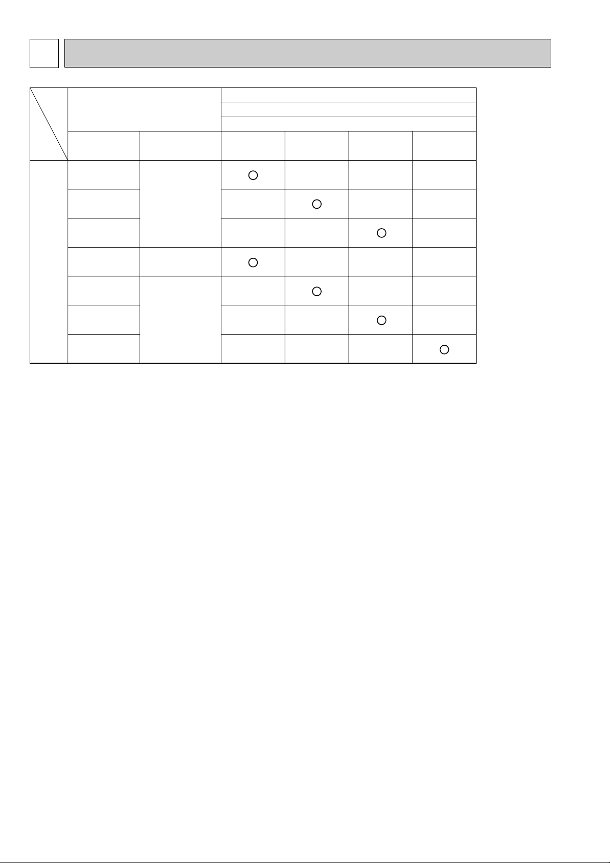
Heat pump type
Outdoor unit
SUZ-
SLZ-A09AR.TH
SLZ-A12AR.TH
SLZ-A18AR.TH
SEZ-A09CR.W
SEZ-A12AR.TH
SEZ-A18AR.TH
SEZ-A24AR.TH
—
—
—
—
—
—
—
—
—
—
—
—
—
—
—
—
—
—
—
—
—
OC302
—
OC303
Indoor unit
Service
Manual No.
Service Ref.
Heat pump
without
electric heater
A12VR.THA09VR.TH A24VR.THA18VR.TH
COMBINATION OF INDOOR AND OUTDOOR UNITS
2
Page 3
Refrigerating
oil
Refrigerant
New refrigerant
R410A
HFC-32: HFC-125 (50%:50%)
Pseudo-azeotropic refrigerant
Not included
A1/A1
72.6
-51.4
1.557
64
Non combustible
0
1730
From liquid phase in cylinder
Possible
Incompatible oil
Non
Non
Previous refrigerant
R22
R22 (100%)
Single refrigerant
Included
A1
86.5
-40.8
0.94
44.4
Non combustible
0.055
1700
Gas phase
Possible
Compatible oil
Light yellow
Non
Refrigerant
Composition (Ratio)
Refrigerant handling
Chlorine
Safety group (ASHRAE)
Molecular weight
Boiling point (:)
Steam pressure [25:](Mpa)
Saturated steam density [25:](Kg/K)
Combustibility
ODP w1
GWP w2
Refrigerant charge method
Additional charge on leakage
Kind
Color
Smell
w1:Ozone Destruction Parameter : based on CFC-11
w2 :Global Warmth Parameter : based on CO
2
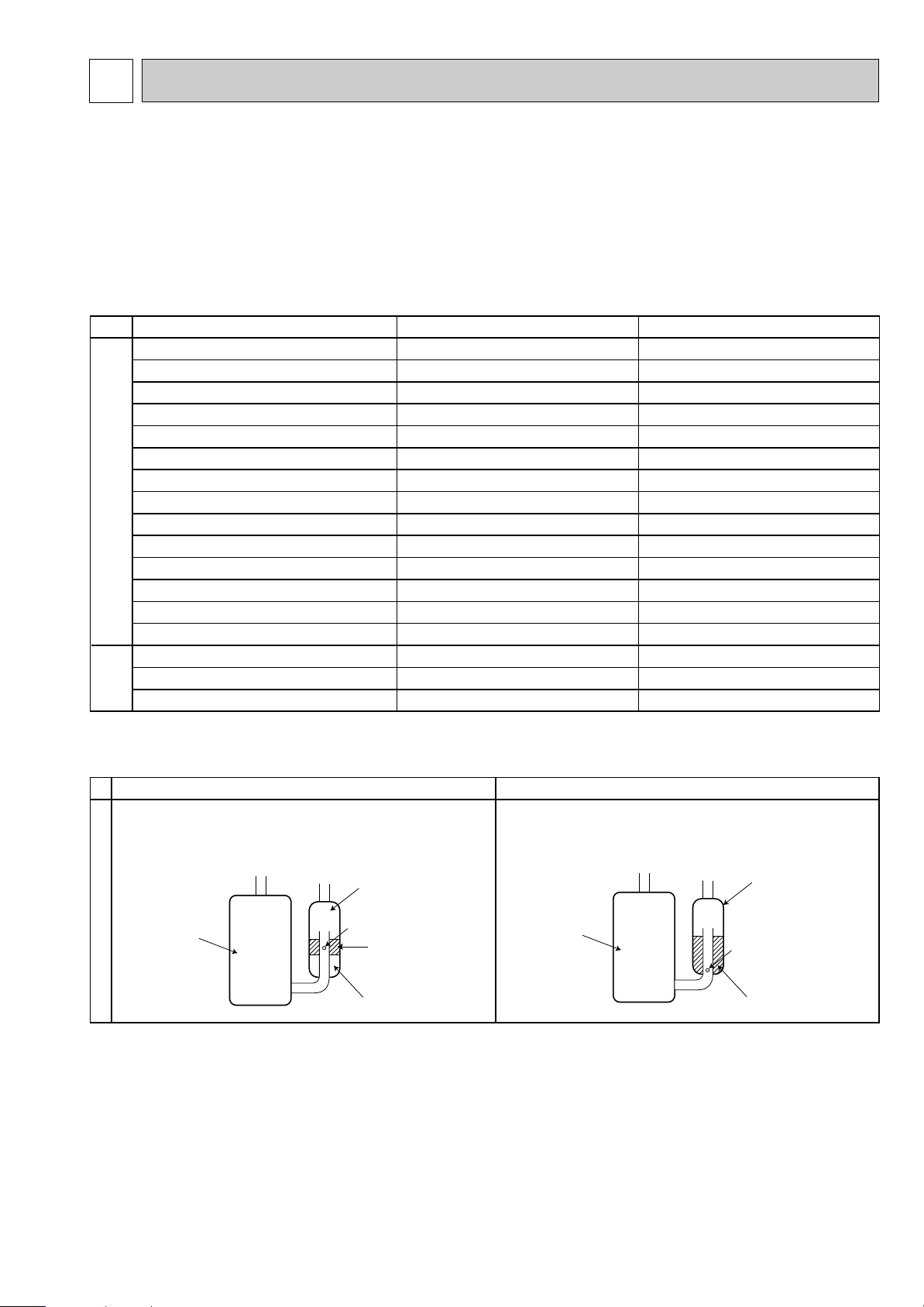
New Specification Current Specification
The incompatible refrigerating oil easily separates from
refrigerant and is in the upper layer inside the suction muffler.
Raising position of the oil back hole enables to back the
refrigerating oil of the upper layer to flow back to the
compressor.
Since refrigerant and refrigerating oil are compatible each,
refrigerating oil backs to the compressor through the lower
position oil back hole.
Compressor
Suction muffler
Oil back hole
Refrigerating oil
Refrigerant
Compressor
Suction muffler
Oil back hole
Refrigerating oil /Refrigerant
Compressor
2
TECHNICAL CHANGES
INFORMATION FOR THE AIR CONDITIONER WITH R410A REFRIGERANT
• This room air conditioner adopts an HFC refrigerant (R410A) which never destroys the ozone layer.
• Pay particular attention to the following points, though the basic installation procedure is same as that for R22 conditioners.
1 As R410A has working pressure approximate 1.6 times as high as that of R22, some special tools and piping parts/
materials are required. Refer to the table below.
2 Take sufficient care not to allow water and other contaminations to enter the R410A refrigerant during storage and
installation, since it is more susceptible to contaminations than R22.
3 For refrigerant piping, use clean, pressure-proof parts/materials specifically designed for R410A. (Refer to 2. Refrigerant
piping.)
4 Composition change may occur in R410A since it is a mixed refrigerant. When charging, charge liquid refrigerant to prevent
composition change.
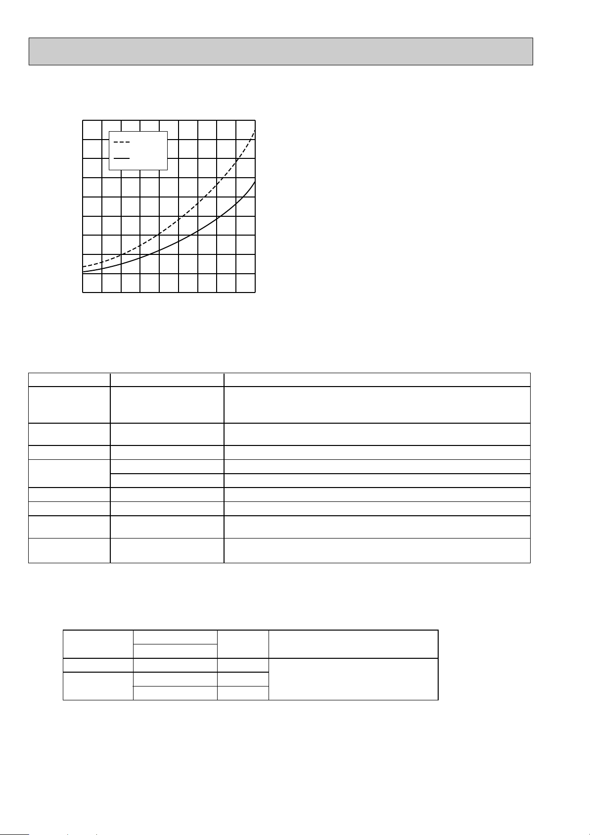
NOTE : The unit of pressure has been changed to MPa on the international system of units(SI unit system).
The conversion factor is: 1(MPa [Gauge]) =10.2(kgf/ff[Gauge])
3
Page 4
-30 -20 -10 0 10 20
30
40 50 60
-0.5
0.0
0.5
1.0
1.5
2.0
2.5
3.0
3.5
4.0
(MPa [Gauge])
R410A
R22
Conversion chart of refrigerant temperature and pressure
Saturated liquid pressure
(:)
NOTE : The unit of pressure has been changed to MPa on the
R410A tools Can R22 tools be used?
Gas leak detector
R410A has high pressures beyond the measurement range of existing
gauges. Port diameters have been changed to prevent any other refrigerant
from being charged into the unit.
Hose material and cap size have been changed to improve the pressure
resistance.
Dedicated for HFC refrigerant.
6.35 mm and 9.52 mm
Description
Clamp bar hole has been enlarged to reinforce the spring strength in the tool.
Provided for flaring work (to be used with R22 flare tool).
Provided to prevent the back flow of oil. This adapter enables you to use
vacuum pumps.
It is difficult to measure R410A with a charging cylinder because the
refrigerant bubbles due to high pressure and high-speed vaporization
No
No
No
Yes
Yes
New
New
New
Gauge manifold
Charge hose
Torque wrench
Flare tool
Flare gauge
Vacuum pump
adapter
Electronic scale for
refrigerant charging
No : Not Substitutable for R410A Yes : Substitutable for R410A
No 12.7 mm
Wall
thickness
Outside diameter
Pipe
mm
For liquid
For gas
6.35
9.52
12.7
0.8 mm
0.8 mm
0.8 mm
Heat resisting foam plastic
Specific gravity 0.045 Thickness 8 mm
Insulation material
international system of units(SI unit system).
The conversion factor is: 1(MPa [Gauge]) =10.2(kgf/ff[Gauge])
1. Tools dedicated for the air conditioner with R410A refrigerant
The following tools are required for R410A refrigerant. Some R22 tools can be substituted for R410Atools.
The diameter of the service port on the stop valve in outdoor unit has been changed to prevent any other refrigerant being
charged into the unit. Cap size has been changed from 7/16 UNF with 20 threads to 1/2 UNF with 20 threads.
2. Refrigerant piping
1 Specifications
Use the refrigerant pipes that meet the following specifications.
• Use a copper pipe or a copper-alloy seamless pipe with a thickness of 0.8 mm. Never use any pipe with a thickness less
than 0.8mm, as the pressure resistance is insufficient.
4
Page 5
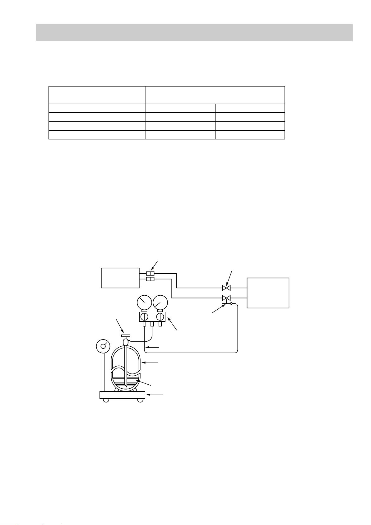
Electronic scale for refrigerant charging
Outdoor unit
Refrigerant gas
cylinder
operating valve
Refrigerant gas cylinder
for R410A with siphon
Refrigerant (liquid)
Service port
Gauge manifold
valve (for R410A)
Union
Liquid pipe
Gas pipe
Stop valve
Indoor unit
Charge hose (for R410A)
R410A
Pipe diameter
mm
6.35
9.52
12.7
17
22
26
Dimension of flare nut
R22
17
22
24
2 Flaring work and flare nut
Flaring work for R410A pipe differs from that for R22 pipe.
For details of flaring work, refer to Installation manual “FLARING WORK”.
3. Refrigerant oil
Apply the special refrigeration oil (accessories: packed with indoor unit) to the flare and the union seat surfaces.
4. Air purge
• Do not discharge the refrigerant into the atmosphere.
Take care not to discharge refrigerant into the atmosphere during installation, reinstallation, or repairs to the refrigerant
circuit.
• Use the vacuum pump for air purging for the purpose of environmental protection.
5. Additional charge
For additional charging, charge the refrigerant from liquid phase of the gas cylinder.
If the refrigerant is charged from the gas phase, composition change may occur in the refrigerant inside the cylinder and the
outdoor unit. In this case, ability of the refrigerating cycle decreases or normal operation can be impossible. However,
charging the liquid refrigerant all at once may cause the compressor to be locked. Thus, charge the refrigerant slowly.
5
Page 6
3
PART NAMES AND FUNCTIONS
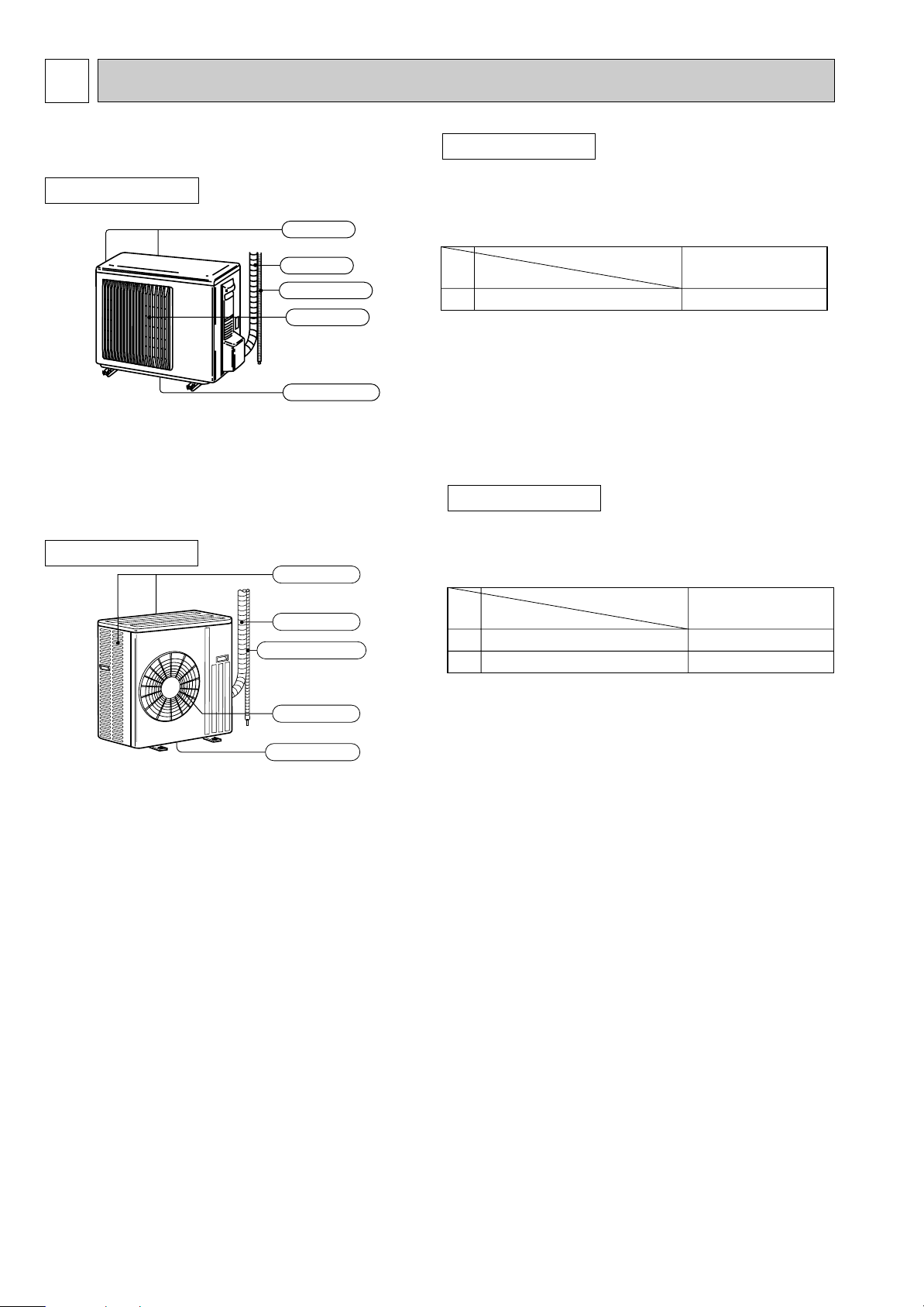
SUZ-A09VR.TH
SUZ-A12VR.TH
OUTDOOR UNIT
SUZ-A18VR.TH
SUZ-A24VR.TH
OUTDOOR UNIT
Air inlet
(back and side)
Piping
Drain hose
Air outlet
Drain outlet
Air inlet
(back and side)
Piping
Drain hose
ACCESSORIES
Drain socket
1
ACCESSORIES
Drain socket
1
Drain cap [33
2
SUZ-A09VR.TH
SUZ-A12VR.TH
1
SUZ-A18VR.TH
SUZ-A24VR.TH
1
2
Air outlet
Drain outlet
6
Page 7
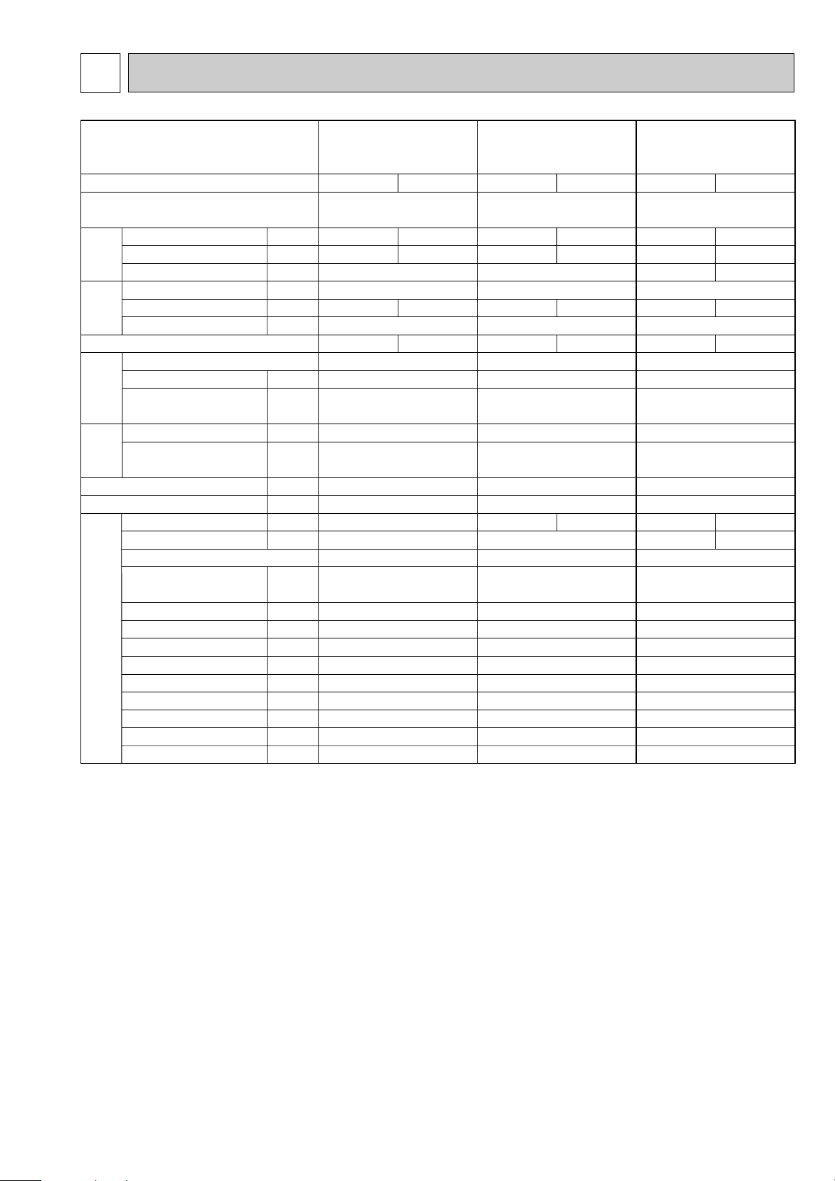
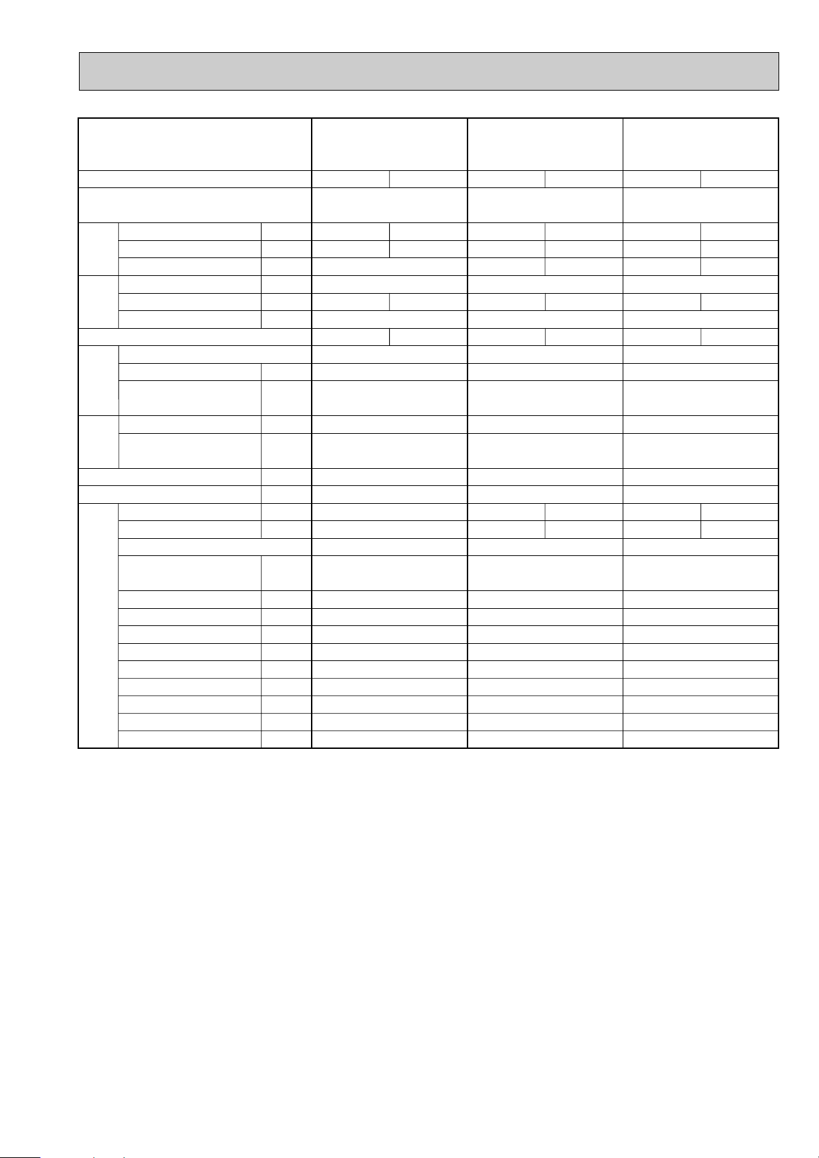
4
Function
Power supply
Outdoor Service Ref.
Capacity Rated frequency(Min.~Max.)
Dehumidification
Air flow(High/Loww)
Starting current ✽1
Compressor motor current ✽1
Fan motor current
Model
Output
Winding
resistance(at 20:)
Model
Winding
resistance(at 20:)
Dimensions WOHOD
Weight
Sound level
Fan speed
Fan speed regulator
Refrigerant filling
capacity(R410A)
Refrigerating oil (Model)
Thermistor RT61 (at 0:)
Thermistor RT62 (at 100:)
Thermistor RT64 (at 50:)
Thermistor RT65 (at 25:)
Thermistor RT61 (at 100:)
Thermistor RT62 (at 25:)
Thermistor RT65 (at 50:)
Thermistor RT68 (at 25:)
kW
r/h
K /h
A
A
A
W
"
"
mm
kg
dB
rpm
kg
cc
k"
k"
k"
k"
k"
k"
k"
k"
Single phase
230V,50Hz
1900
4.20
0.24
KNB073FBVH
550
U-V 1.53 U-W 1.53
V-W 1.53
RA6V21-AA
WHT-BLK 347
BLK-RED 281
800o550o285
33
46
825
1
0.80
320 (NEO22)
32.6
13.4
17
10
—
—
—
—
Cooling
2.5(0.9-3.2)
1.4
3.28
3.29
Heating
3.0(0.9-4.3)
—
3.78
3.45
SUZ-A09VR.TH
Indoor Service Ref.
SLZ-A09AR.TH
Indoor Service Ref.
SLZ-A12AR.TH
Compressor
Fan
motor
Special
remarks
Coefficient of performance (C.O.P)
Capacity
Electrical
data
SUZ-A12VR.TH
Single phase
230V,50Hz
1900
4.90
0.24
KNB092FAAH
650
U-V 0.49 U-W 0.49
V-W 0.49
RA6V21-AA
WHT-BLK 347
BLK-RED 281
800o550o285
34
825
1
0.90
320 (NEO22)
32.6
13.4
17
10
—
—
—
—
Cooling
3.2(1.0-3.6)
1.8
4.43
3.02
47
Heating
3.8(0.9-4.8)
—
4.43
3.55
48
Indoor Service Ref.
SLZ-A18AR.TH
SUZ-A18VR.TH
Single phase
230V,50Hz
7.40
0.30
SNB130FLDH
850
U-V 0.45 U-W 0.45
V-W 0.45
PM8H60-UB
BLK-WHT 15.2
840o850o330
53
2
1.80
450 (NEO22)
—
—
—
—
13.4
10.0
17.0
10.0
Cooling
4.6(1.1-5.2)
2.3
2,940/1,320w
6.86
2.82
WHT-RED 15.2
53/50w
800/400w
Heating
5.0(0.9-6.5)
—
2,940/2,210w
6.46
3.23
RED-BLK 15.2
55/53w
800/620w
SPECIFICATION
SLZ-A•AR.TH / SUZ-A•VR.TH
NOTE : Test conditions are based on ISO 5151
Cooling : Indoor D.B. 27: W.B. 19:
Outdoor D.B. 35: W.B. 24:
Heating : Indoor D.B. 20: W.B. 15:
Outdoor D.B. 7: W.B. 6:
Refrigerant piping length (one way): 5m
✽1 Measured under rated operating frequency.
7
Page 8
SUZ-A09VR.TH
Indoor Service Ref. SEZ-A09CR.W
Function
Power supply
Capacity Rated frequency(Min.~Max.)
Dehumidification
Air flow
Starting current ✽1
Compressor motor current ✽1
Fan motor current
Model
Output
Winding
resistance(at 20:)
Model
Winding
resistance(at 20:)
Dimensions WOHOD
Weight
Sound level
Fan speed
Fan speed regulator
Refrigerant filling
capacity(R410A)
Refrigerating oil (Model)
Thermistor RT61(at 0:)
Thermistor RT62(at 100:)
Thermistor RT64(at 50:)
Thermistor RT65(at 25:)
kW
r/h
K /h
A
A
A
W
"
"
mm
kg
dB
rpm
kg
cc
k"
k"
k"
k"
Compressor
Fan
motor
Special
remarks
Coefficient of performance(C.O.P)
Capacity
Electrical
data
Outdoor Service Ref.
Single phase
230V,50Hz
1900
4.30
0.24
KNB073FBVH
550
U-V 1.53 U-W 1.53
V-W 1.53
RA6V21-AA
WHT-BLK 347
BLK-RED 281
800o550o285
33
46
825
1
0.80
320 (NEO22)
32.6
13.4
17
10
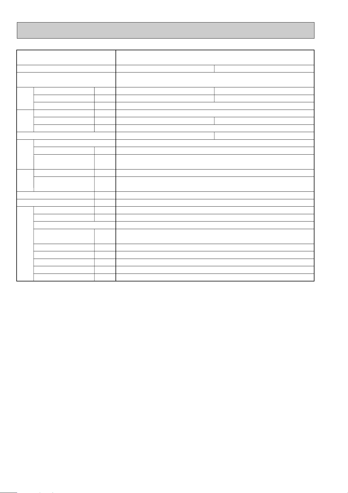
Cooling
2.4 (1.0-3.2)
1.4
3.08
3.24
Heating
3.0 (0.9-4.2)
—
3.78
3.41
SEZ-A•CR.W / SUZ-A•VR.TH
NOTE : Test conditions are based on ISO 5151
Cooling : Indoor D.B. 27: W.B. 19:
Heating : Indoor D.B. 20: W.B. 15:
Refrigerant piping length (one way): 5m
✽1 Measured under rated operating frequency.
Outdoor D.B. 35: W.B. 24:
Outdoor D.B. 7: W.B. 6:
8
Page 9
SEZ-A•AR.TH / SUZ-A•VR.TH
Outdoor Service Ref.
Function
Power supply
Capacity Rated frequency(Min.~Max.)
Dehumidification
Air flow(High/Loww)
Capacity
Starting current ✽1
Compressor motor current ✽1
Fan motor current
Electrical
data
Coefficient of performance(C.O.P)
Model
Output
Winding
resistance(at 20:)
Compressor
Model
Winding
Fan
motor
resistance(at 20:)
Dimensions WOHOD
Weight
Sound level(High/Loww)
Fan speed(High/Loww)
Fan speed regulator
Refrigerant filling
capacity(R410A)
Refrigerating oil (Model)
Thermistor RT61 (at 0:)
Thermistor RT62 (at 100:)
Special
remarks
Thermistor RT64 (at 50:)
Thermistor RT65 (at 25:)
Thermistor RT61 (at 100:)
Thermistor RT62 (at 25:)
Thermistor RT65 (at 50:)
Thermistor RT68 (at 25:)
kW
r/h
K /h
A
A
A
W
"
"
mm
kg
dB
rpm
kg
cc
k"
k"
k"
k"
k"
k"
k"
k"
SUZ-A12VR.TH
Indoor Service Ref.
SEZ-A12AR.TH
Cooling
Single phase
230V,50Hz
3.4 (1.0-3.8)
1.9
4.55
3.12
KNB092FAAH
U-V 0.49 U-W 0.49
V-W 0.49
RA6V21-AA
WHT-BLK 347
BLK-RED 281
800o550o285
320 (NEO22)
Heating
3.9 (0.9-5.0)
—
1900
5.00
4.45
0.24
3.55
650
34
47
825
1
0.90
32.6
13.4
17
10
—
—
—
—
SUZ-A18VR.TH
Indoor Service Ref.
SEZ-A18AR.TH
Cooling
Single phase
230V,50Hz
5.0(1.1-5.6)
2.5
2,940/1,640w
7.43
2.81
SNB130FLDH
U-V 0.45 U-W 0.45
V-W 0.45
PM8H60-UB
BLK-WHT 15.2
WHT-RED 15.2
840o850o330
53/51w
800/480w
450 (NEO22)
Heating
5.9(1.1-7.2)
—
2,940/2,210w
8.50
7.93
0.30
3.21
850
RED-BLK 15.2
53
55/53w
800/620w
2
1.80
—
—
—
—
13.4
10.0
17.0
10.0
SUZ-A24VR.TH
Indoor Service Ref.
SEZ-A24AR.TH
Cooling
Single phase
230V,50Hz
5.5(1.1-6.3)
3.3
2,940/1,640w
8.36
2.81
SNB130FLDH
U-V 0.45 U-W 0.45
V-W 0.45
PM8H60-UB
BLK-WHT 15.2
WHT-RED 15.2
840o850o330
53/51w
800/480w
450 (NEO22)
Heating
6.9(0.9-8.0)
—
2,940/2,210w
10.40
9.76
0.30
2.82
850
RED-BLK 15.2
53
55/53w
800/620w
2
1.80
—
—
—
—
13.4
10.0
17.0
10.0
NOTE : Test conditions are based on ISO 5151
Cooling : Indoor D.B. 27: W.B. 19:
Outdoor D.B. 35: W.B. 24:
Heating : Indoor D.B. 20: W.B. 15:
Outdoor D.B. 7: W.B. 6:
Refrigerant piping length (one way): 5m
✽1 Measured under rated operating frequency.
9
Page 10
Model
Item
Current transformer
Current transformer
Smoothing capacitor
Outdoor fan capacitor
Diode module
Fuse
Fuse
Power transistor module
Expansion valve coil
Reactor
Current-detecting resistor
Current-detecting resistor
Current-limiting resistor
Solid state relay
Terminal block
Relay
Relay
R.V. coil
Outdoor fan motor thermal fuse
SUZ-A09VR.TH SUZ-A12VR.TH
(CT)
(CT761, CT781)
(
C62A, C62B, C61B
)
(C65)
(DB61, DB65)
(F61)
(F71, F801)
(IPM)
(LEV)
(L61)
(R61)
(R831)
(
R64A, R64B
)
(SR61)
(TB)
(X63)
(X64)
(21S4)
ETQ19Z53AY
ETQ19Z71AY
680+ 420V
1.8+ 440V
D25XB60
250V 20A
250V 3.15A
PS21244A
CAD-MD12ME 12VDC
10A 23.0mH
25m" 5W
5.1" 10W
G3MB
3P
G5N-1a/G5NB-1a
G4A-1A-PS
LD30013
Open 152:
45m" 5W 50m" 5W (2 elements)
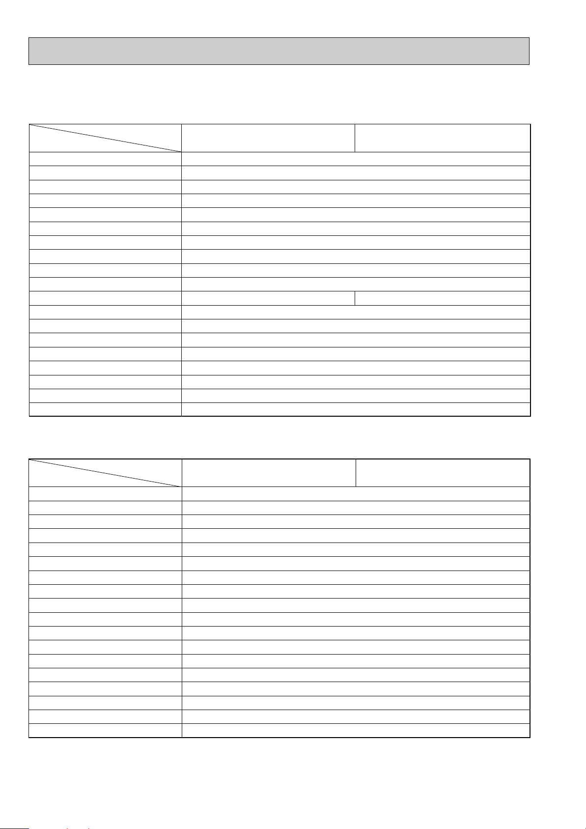
Specifications and rating conditions of main electric parts
Service Ref.
Item
Smoothing capacitor
Current transformer
Current transformer
Fuse
Fuse
Fet array
Power transistor module
Reactor
Expansion valve
Power factor controller
Resistor
Resistor
Resistor
Solenoid coil relay
Terminal block
Terminal block
Relay
R.V. coil
SUZ-A18VR.TH
(CB1,2,3)
(CT1,2)
(CT61)
(F801, F912)
(F911)
(HC932)
(IPM)
(L)
(LEV)
(PFC)
(R64)
(R934A,B)
(RS1~4)
(SSR61)
(TB1)
(TB2)
(X64)
(21S4)
SUZ-A24VR.TH
560+ 450V
ETQ19Z68AY
ETQ19Z53AY
250V 3.15A
250V 1A
SLA5075
PS21244-A
340µH 20A
CAM-30YGME 12VDC
PS51259-A
10" 20W
1.1" 2W 2%
0.04" 7W
TLP3506
3P
2P
G4A
LD30013
SUZ-A09VR.TH
SUZ-A12VR.TH
SUZ-A18VR.TH
SUZ-A24VR.TH
10
Page 11
5
90
80
70
60
50
40
30
20
10
63 125 250 500 1000 2000 4000 8000
NC-60
NC-50
NC-40
NC-30
NC-20
NC-70
OCTAVE BAND SOUND PRESSURE LEVEL, dB (0 dB = 0.0002 µbar)
BAND CENTER FREQUENCIES, Hz
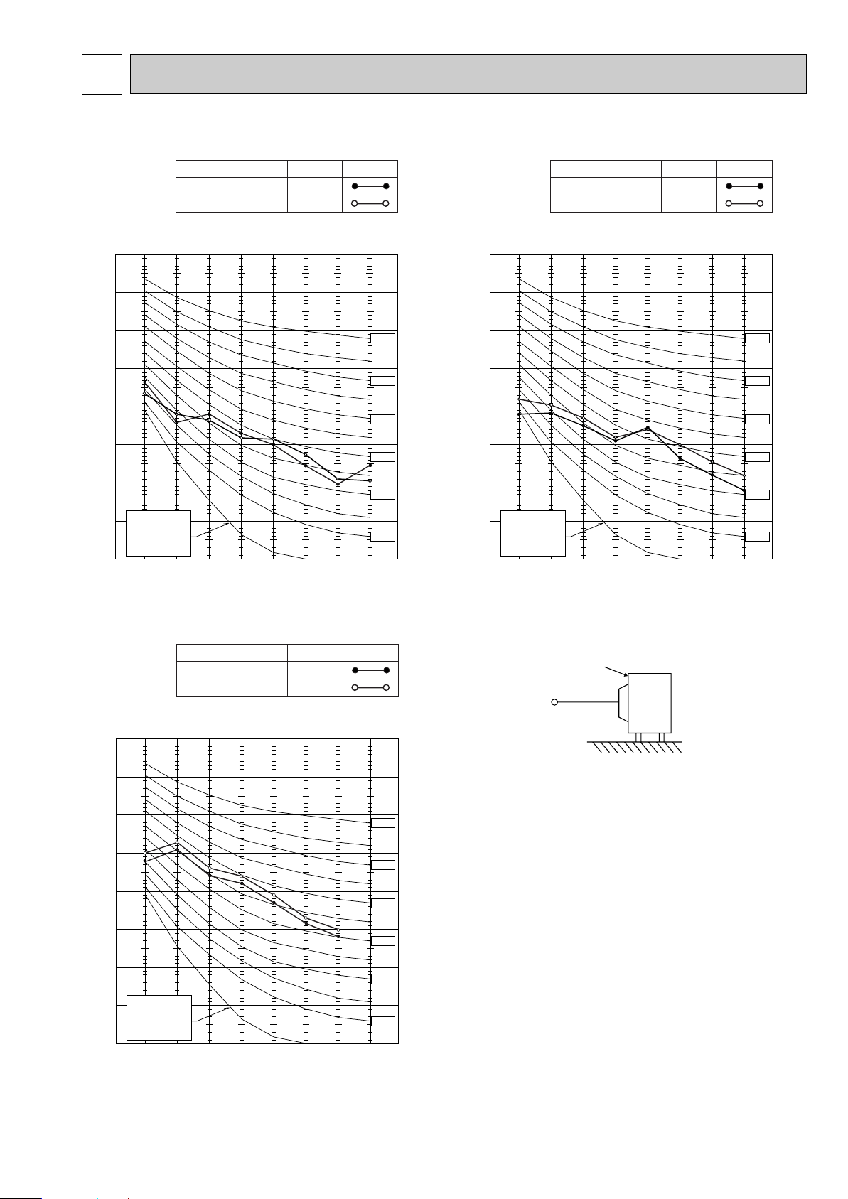
Test conditions,
Cooling : Dry-bulb temperature 35: Wet-bulb temperature (24:)
APPROXIMATE
THRESHOLD OF
HEARING FOR
CONTINUOUS
NOISE
COOLING
FUNCTION
SPL(dB) LINE
High
SPEED
HEATING
46
46
Heating : Dry-bulb temperature 7: Wet-bulb temperature 6:
90
80
70
60
50
40
30
20
10
63 125 250 500 1000 2000 4000 8000
NC-60
NC-50
NC-40
NC-30
NC-20
NC-70
OCTAVE BAND SOUND PRESSURE LEVEL, dB (0 dB = 0.0002 µbar)
BAND CENTER FREQUENCIES, Hz
APPROXIMATE
THRESHOLD OF
HEARING FOR
CONTINUOUS
NOISE
COOLING
FUNCTION
SPL(dB)
LINE
High
FAN SPEED
HEATING
47
48
Test conditions,
Cooling : Dry-bulb temperature 35: Wet-bulb temperature (24:)
Heating : Dry-bulb temperature 7: Wet-bulb temperature 6:
OUTDOORUNIT
MICROPHONE
1m
COOLING
FUNCTION
SPL(dB(A)) LINE
High
SPEED
HEATING
53
55
90
80
70
60
50
40
30
20
10
63 125 250 500 1000 2000 4000 8000
NC-60
NC-50
NC-40
NC-30
NC-20
NC-70
BAND CENTER FREQUENCIES, Hz
Test conditions,
Cooling : Dry-bulb temperature 35: Wet-bulb temperature (24:)
APPROXIMATE
THRESHOLD OF
HEARING FOR
CONTINUOUS
NOISE
Heating : Dry-bulb temperature 7: Wet-bulb temperature 6:
OCTAVE BAND SOUND PRESSURE LEVEL, dB (0 dB = 0.0002 µbar)
NOISE CRITERIA CURVES
SUZ-A09VR.TH
SUZ-A12VR.TH
SUZ-A18VR.TH
SUZ-A24VR.TH
11
Page 12
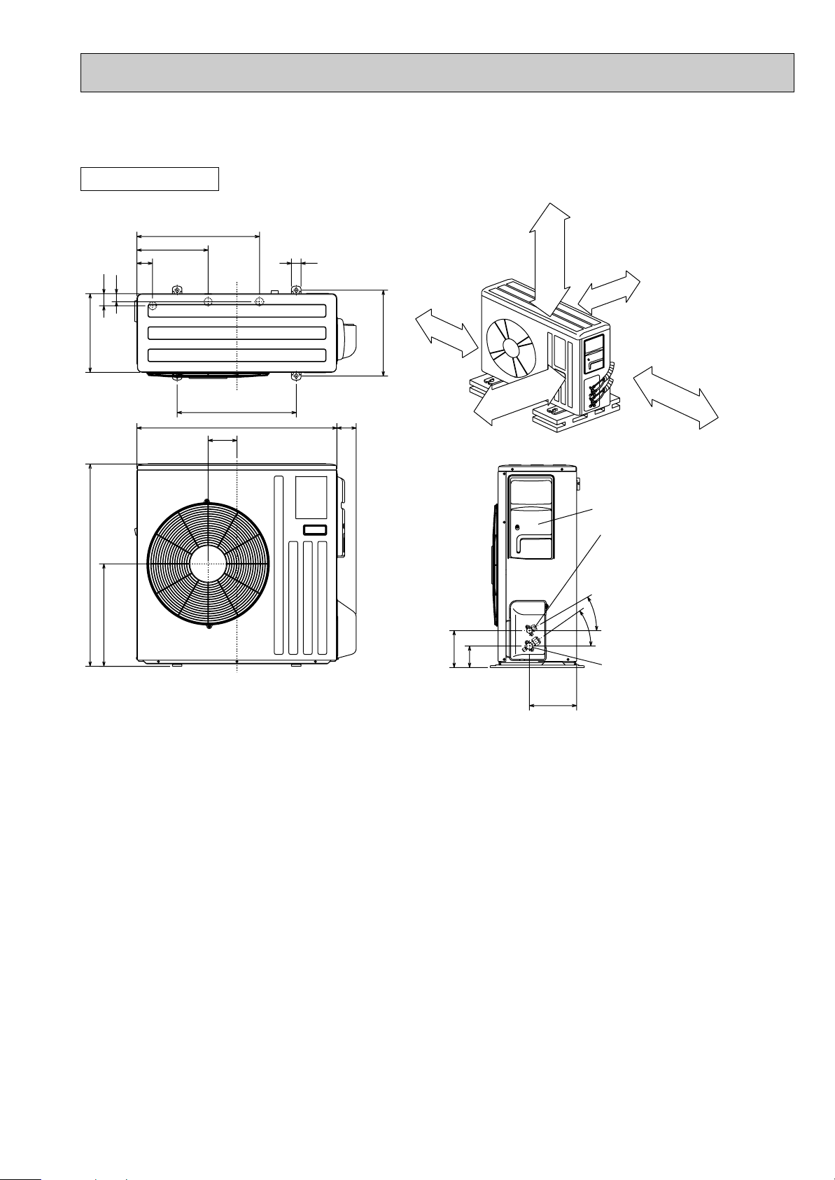
6
10
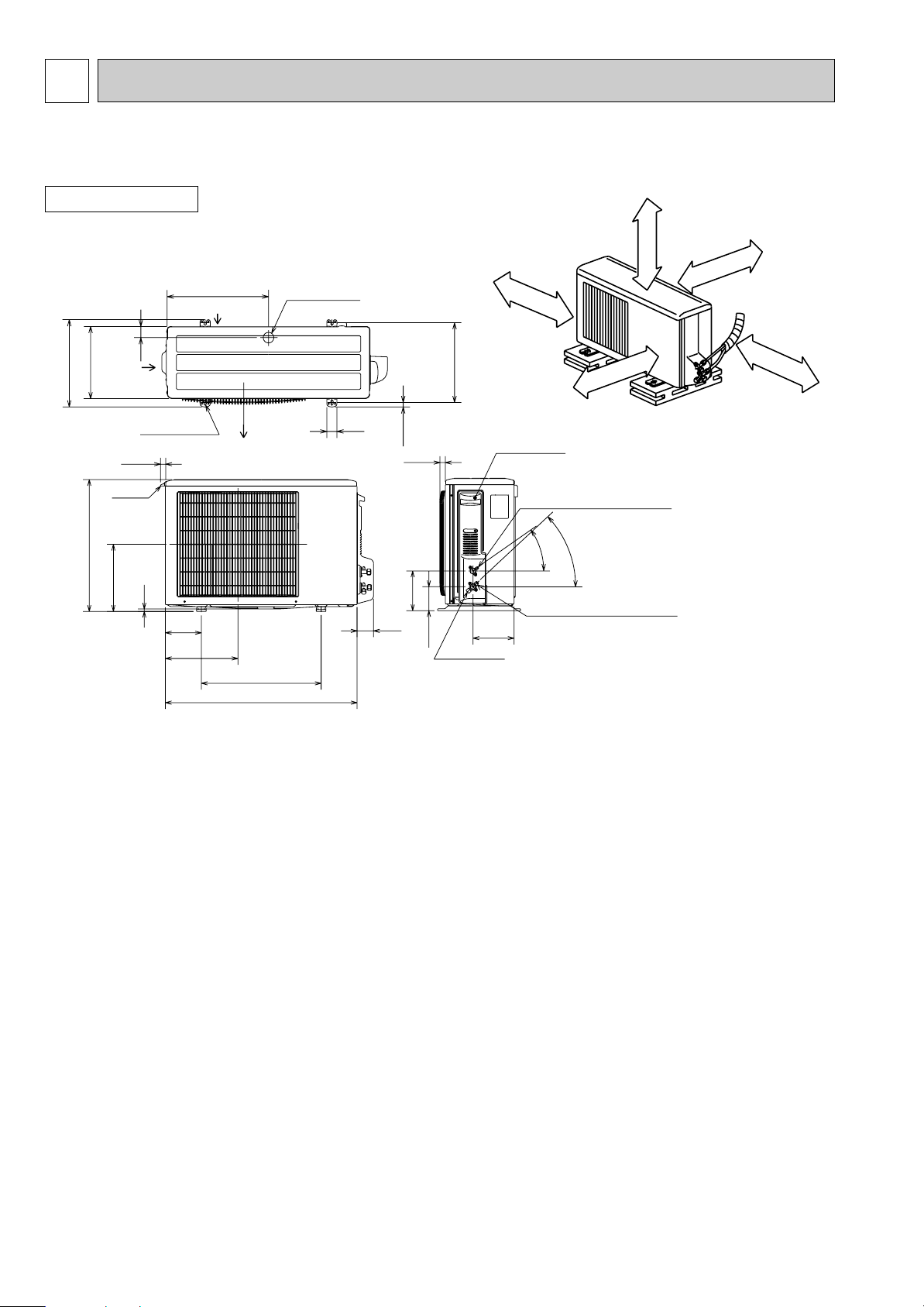
69
800
302.5
500 Bolt pitch for installation
150
22.3
Handle
550
280
164.5
99.5
170.5
23
Service panel
Service port
285
344.5
44
400
Air in
Air out
Air in
17.5
Bolt pitch for
installation
304~325
40
Liquid refrigerant pipe joint
Refrigerant pipe (flared) [6.35
Gas refrigerant pipe joint
Refrigerant pipe (flared) [9.52
43-
35-
2 holes 10o21
Drain hole [42
REQUIRED SPACE
Basically open 100mm or more
without any obstruction in front
and on both sides of the unit.
350mm or more
200mm or more
100mm or more
100mm or more
Open two sides of left,
right, or rear side.
OUTLINES AND DIMENSIONS
SUZ-A09VR.TH
SUZ-A12VR.TH
OUTDOOR UNIT
Unit: mm
12
Page 13
30-
35-
155
90
198
40
515
299
66
34
51
330
360
850
430
500
80
121
840
Open as a rule
500mm or more if
the front and both
sides are open
100mm or more
200mm or more if
there are obstacles
to both sides
Open as a rule
500mm or more if the back,
both sides and top are open
350mm or more
100mm or more
Service panel
Gas refrigerant
pipe joint
Refrigerant pipe
(flared) [12.7·····(SUZ-A18VR.TH)
[15.88···(SUZ-A24VR.TH)
Liquid refrigerant
pipe joint
Refrigerant pipe
(flared) [6.35
REQUIRED SPACE
SUZ-A18VR.TH
SUZ-A24VR.TH
OUTDOOR UNIT
Unit: mm
13
Page 14
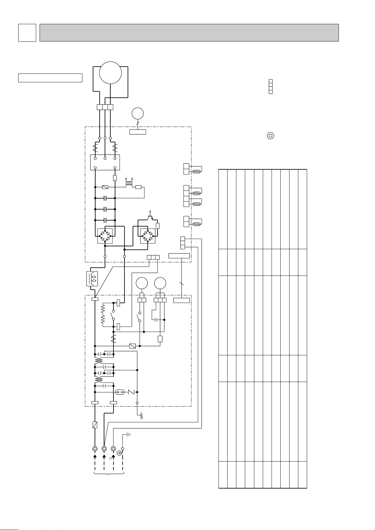
7
WIRING DIAGRAM
SUZ-A09VR.TH
SUZ-A12VR.TH
OUTDOOR UNIT
BLK
U
1
BLK
LD-U
U
P
W
RED
2
RED
WHT
LD-V
CT761
V
F801
C61B
C62B
+++
C62A
MC
3
LD-W
N
CN61
W
R61
V
WHT
C
CT781
IPM
T801
6
N
LEV
724
IC801
CN642
421
3
INVERTER P.C. BOARD
CN641
TR821
R831
2
112
CN643
RT64
RT61 RT62
RT65
refer to the indoor unit electric wiring
diagram for servicing.
(For field wiring)
: Terminal block, : Connector
2. Use copper conductors only.
3. Symbols below indicate.
Terminal 3 has 12V DC against terminal N.
However, between Terminal 3 and N, these
NOTE: 1. About the indoor side electric wiring
★ The 12V DC is NOT always against the ground.
NAME
terminals are NOT electrically insulated by the
transformer or other device.
BLK
L61
BLK
DB61
TAB63
R64B
R64A
L63
L62
TAB61
WHT
F61
WHT
TB
2
230V~
BLU
N
LD70
X64
TAB62
BLU
RED
3
12V
★
LD69
BLK
BLU
BLU
4
X63
3
F71
CT
DSA
NR61
GRN
GRN/YLW
21S4
1
LDE
2
DB65
123
1
CN721
C65
SR61
CN800
MF
3
2
213
CN601
725
C
N
7
726
C
N
CN771
POWER P.C. BOARD
AMBIENT TEMPERA TURE THERMIST OR
CURRENT-DETECTING RESISTOR
CURRENT-LIMITING RESISTOR
SYMBOL
RT65
R61,R831
R64A,R64B
NAME
EXPANSION VALVE COIL
REACTOR
CMC COIL
SYMBOL
LEV
L61
L62,L63MCMF
NAME
CURRENT TRANSFORMER
SMOOTHING CAPACITOR
FAN MOTOR CAPACITOR
SOLID STATE RELAY
TERMINAL BLOCK
SWITCHING POWER TRANSISTOR
TRANSFORMER
RELAY
SR61TBTR821
COMPRESSOR
DIODE MODULE
T801
X63,X64
FAN MOTOR
VARISTOR
DEFROST THERMISTOR
DISCHARGE TEMPERATURE THERMIST OR
NR61
RT61
RT62
SURGE ABSORBER
FUSE (20A)
FUSE (3.15A)
INTELLIGENT POWER DEVICE
REVERSING VALVE COIL
21S4
FIN TEMPERATURE THERMIST OR
RT64
POWER TRANSISTOR MODULE
TO
INDOOR
UNIT
CONNECTING
14
SYMBOL
CT,CT761,CT781
C62A,C62B,C61B
C65
DB61,DB65
DSA
F61
F71,F801
IC801
IPM
Page 15
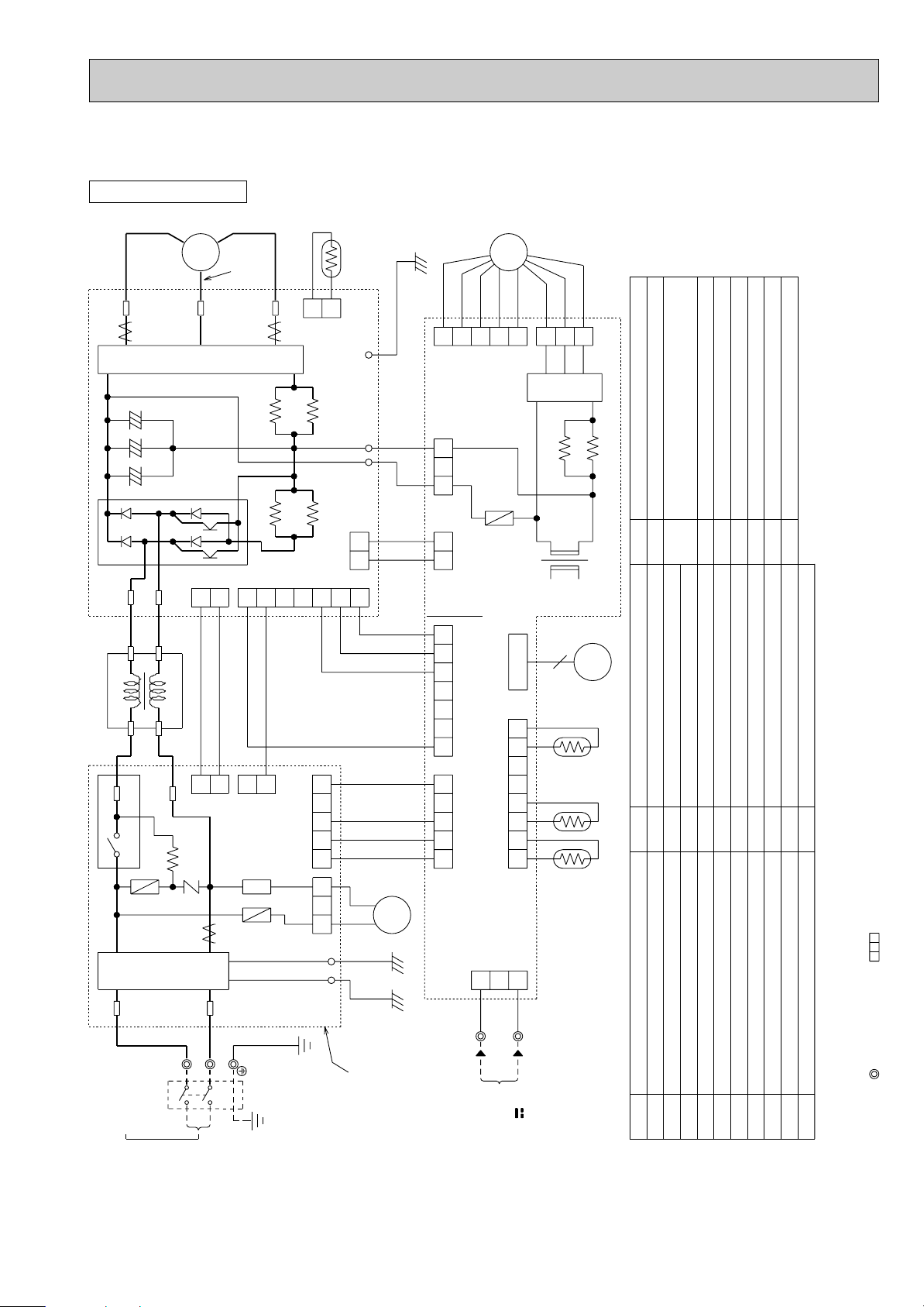
SUZ-A18VR.TH
SUZ-A24VR.TH
OUTDOOR UNIT
L
RED
W
CT2
PFC
R
1
2
S
RED
W
CB3
CB2
CB1
YLW
4
3
V
V
BLK
MC
IPM
BLK
U
WHT
CN5
21
BLK
U
21
CN3
CT1
RS3
RS4
RS2
RS1
CN4
CN2
27
6543 1
BLK
RT65
POWER
BOARD
LD9
LD1LD2
12
GRN
WHT
RED
BLK
BLK
BLK
BLK
BLK
BLU
ORN
PNK
GRY
CN801
13
12
CN701
CN702
MF
YLW
CN931
F801
CN7954123 78
RED
R934A
T801
WHT
231 34512
6
BLK
CN932
HC932
LEV
R934B
NAME
REVERSING VALVE SOLENOID COIL
FIN TEMP.THERMISTORRT65
SYMBOL
SOLENOID COIL RELAY
OUTDOOR HEAT EXCHANGER
TEMPERATURE THERMISTOR
SSR61
RT68
TERMINAL BLOCK
TERMINAL BLOCK
TRANSFORMER
21S4
TB2
X64 RELAY
TB1
T801
NAME
RED
4X64
TAB4
R64
F912
NF
TAB1
BRN
CIRCUIT
BREAKER
POWER SUPPLY
~/N 230V 50Hz
YLW
TB1
NR63
BLU
L
21
CN903
CT61
TAB2
PE
N
21
CN902
SSR61
F911
GRN/YLW
5123
CN901
CN912
13
LDE2
LDE1
BLK
1 567
BLK
5321
BLK
BLK
BLK
BLU
BLU
21S4
GRN
GRN
NOISE FILTER
P.C.BOARD
ELECTRONIC CONTROL
CN661
CN781
1
P.C.BOARD
BLU
RED
3
TB2
TO INDOOR
UNIT
CONNECTING
CN601
3
N
12V
RT62 RT61 RT68
RESISTOR
FAN MOTOR(INNER FUSE)MF
NOISE FILTERNF
VARISTOR
NR63
COMPRESSOR
MC
SYMBOL
RESISTOR
POWER FACTOR CONTROLLER
RESISTORR64
RS1~4
R934A,B
PFC
NAME
FUSE(250V 3.15A)F801
FUSE(250V 1A)F911
FUSE(250V 3.15A)F912
FET ARRAY
CURRENT TRANSFORMER
CURRENT TRANSFORMER
SMOOTHING CAPACITOR
CT1,2
CB1~3
SYMBOL
CT61
POWER TRANSISTOR MODULEIPM
HC932
DISCHARGE TEMP.THERMISTORRT61
DEFROST TEMP.THERMISTOR
RT62
2. Use copper conductors only(for field wiring).
3. Symbols below indicate.
1. About the indoor side electric wiring refer to the indoor unit electric wiring diagram for servicing.
REACTOR
EXPANSION VALVELEV
L
NOTES
:Terminal block :Connector
15
Page 16
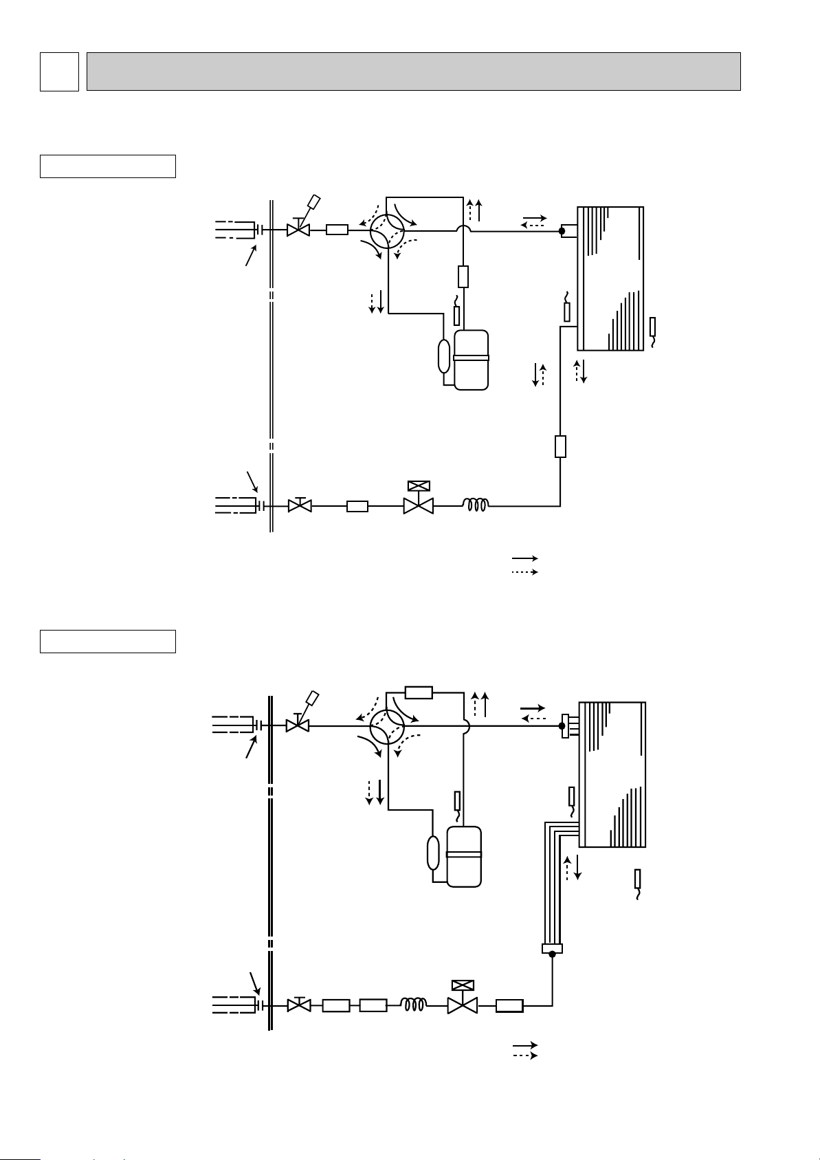
8
Outdoor
heat
exchanger
Flared connection
Defrost
thermistor
RT61
Discharge
temperatuer
thermistor
RT62
Flared connection
Stop valve
(with strainar)
Stop valve
(with service port)
Refrigerant flow in cooling
Compressor
Muffler
4-way valve
Refrigerant flow in heating
Refrigerant pipe [9.52
(with heat insulator)
Refrigerant pipe
[6.35
(with heat insulator)
R.V. coil
heating ON
cooling OFF
Ambient
temperature
thermistor
RT65
Strainer
#100
Capillary tube
[3.0✕[2.0✕200
Expansion
valve
Muffler
Muffler
Outdoor
heat
exchanger
Flared connection
Defrost
thermistor
RT62
Discharge
temperature
thermistor
RT61
Flared connection
Stop valve
Stop valve
(with service port)
Capillary tube
[3.6✕[2.4✕50
Refrigerant flow in cooling
Compressor
4-way valve
Refrigerant flow in heating
Refrigerant pipe [12.7 (SUZ-A18VR.TH)
(with heat insulator) [15.88 (SUZ-A24VR.TH)
Refrigerant pipe [6.35
(with heat insulator)
LEV
R.V. coil
heating ON
cooling OFF
Muffler
#100
Strainer
#100
Receiver
Outdoor heat
exchanger
temperature
thermistor
RT68
Strainer
#100
REFRIGERANT SYSTEM DIAGRAM
SUZ-A09VR.TH
SUZ-A12VR.TH
OUTDOOR UNIT
Unit:mm
SUZ-A18VR.TH
SUZ-A24VR.TH
OUTDOOR UNIT
16
Unit:mm
Page 17
Outdoor unit
precharged
800
900
14m
270
270
7m
0
0
6m
0
0
5m
0
0
11m
180
180
Models
Refrigerant piping length (one way)
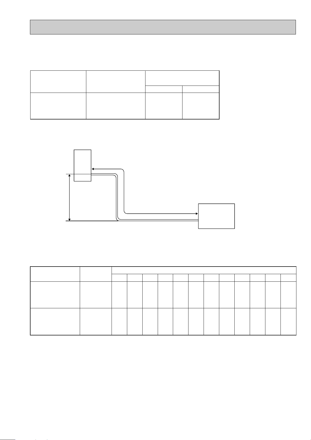
Calculation : Xg=30g/mo(Refrigerant piping length(m) - 5)
8m
90
90
9m
120
120
10m
150
150
12m
210
210
13m
240
240
15m
300
300
20m
450
450
SUZ-A09VR.TH
SUZ-A12VR.TH
Refrigerant Piping
Max. length
A
w Height difference should be within 12m regardless of which unit, indoor or outdoor position is high.
w Max. Height
difference 12m
Indoor
unit
(SLZ/SEZ)
Outdoor unit
Refrigerant piping
Max. length : m
A
20
Gas
9.52
Liquid
6.35
Piping size O.D : mm
Models
SUZ-A09VR.TH
SUZ-A12VR.TH
SUZ-A09VR.TH
SUZ-A12VR.TH
MAX. REFRIGERANT PIPING LENGTH
MAX. HEIGHT DIFFERENCE
ADDITIONAL REFRIGERANT CHARGE (R410A:g)
17
Page 18
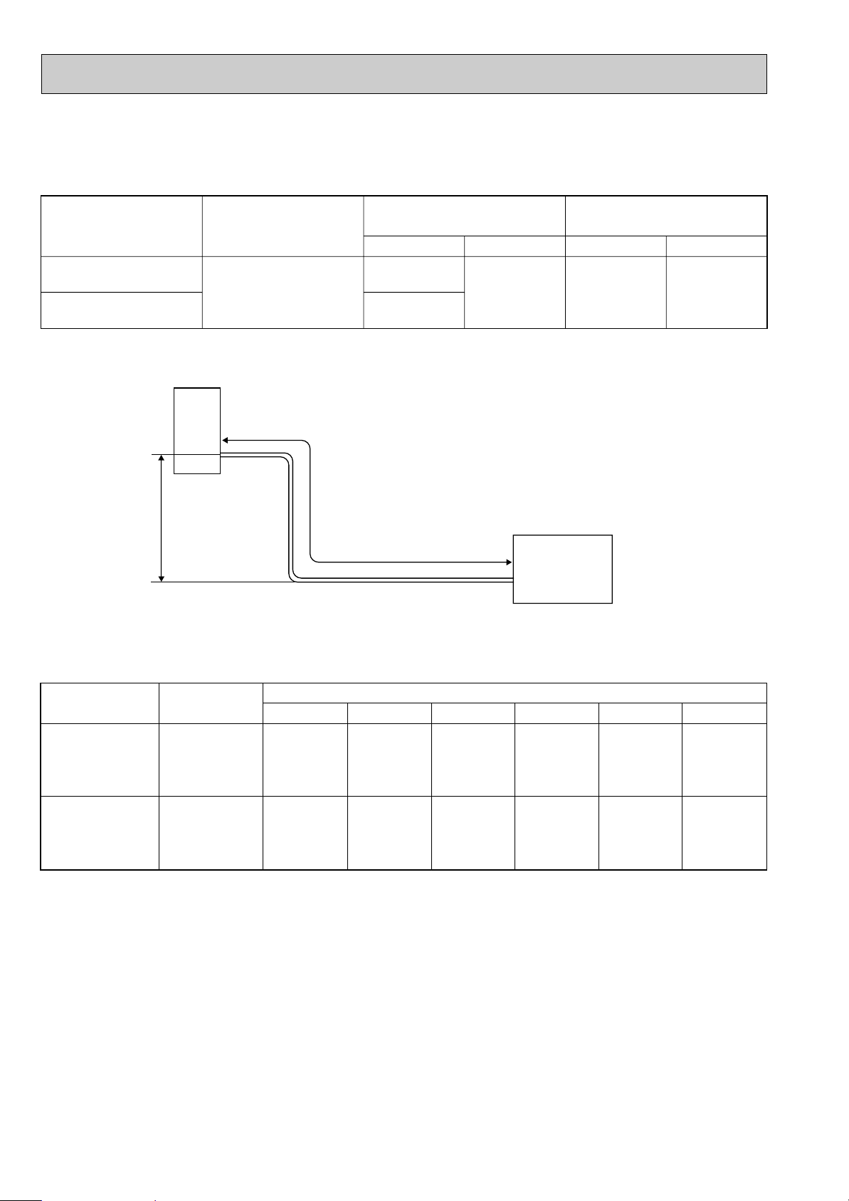
Refrigerant Piping
Max. length
A
w Height difference should be within 15m regardless of which unit, indoor or outdoor position is high.
w Max. Height
difference 15m
Indoor
unit
Outdoor unit
(SLZ/SEZ)
Refrigerant piping
Max. length : m
A
30
Indoor unit
Gas 0.43
Liquid 0.5
Gas
12.7
15.88
Liquid
6.35
Outdoor unit
Gas 0
Liquid 0
SUZ-A18VR.TH
SUZ-A24VR.TH
Model
Piping size O.D : mm Length of connecting pipe : m
Refrigerant piping length (one way)
Outdoor unit
precharged
15m
160
160
20m
260
260
25m
360
360
30m
460
460
7m
0
0
10m
60
60
Model
SUZ-A18VR.TH
SUZ-A24VR.TH
1,800
1,800
SUZ-A18VR.TH
SUZ-A24VR.TH
MAX. REFRIGERANT PIPING LENGTH
MAX. HEIGHT DIFFERENCE
ADDITIONAL REFRIGERANT CHARGE(R410A : g)
Calculation : Xg=20g/m ✕ (Refrigerant piping length (m)–7)
18
Page 19
9
Wet-and dry-bulb
thermometers
BACK VIEW
Indoor air Wet-bulb temperature
difference (degree)
Indoor intake air Wet-bulb temperature (:)
Outdoor intake air Dry-bulb temperature (:)
Indoor intake air Wet-bulb temperature (
:)
Outdoor intake air Dry-bulb temperature (:)
SUZ-A09VR.TH
6.6
6.1
5.6
5.2
4.7
4.2
8.0
7.5
6.9
6.3
5.7
5.2
Rated frequency 57Hz
SUZ-A12VR.TH
Rated frequency 67Hz
10.8
10.0
9.2
8.5
7.7
6.9
SUZ-A18VR.TH
Rated frequency 75Hz
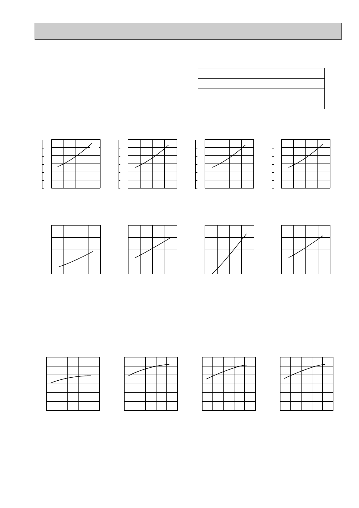
PERFORMANCE CURVES
● SLZ-A09AR.TH / SUZ-A09VR.TH
● SLZ-A12AR.TH / SUZ-A12VR.TH
● SLZ-A18AR.TH / SUZ-A18VR.TH
The standard data contained in these specifications apply only to the operation of the air conditioner under normal condition.
Operating conditions vary according to the areas where these units are installed. The following information has been provided
to clarify the operating characteristics of the air conditioner under the conditions indicated by the performance curve.
(1) GUARANTEED VOLTAGE
Rated voltage : ±10% (207~253V), 50Hz
(2) AIR FLOW
Air flow should be set at MAX.
(3) MAIN READINGS
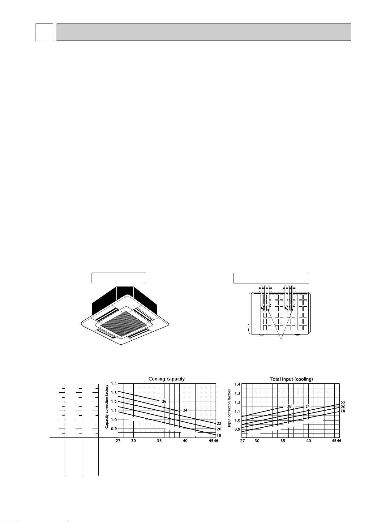
COOLING
(1) Indoor intake air wet-bulb temperature : W.B. ˚C
(2) Indoor outlet air wet-bulb temperature : W.B. ˚C
(3) Outdoor intake air dry-bulb temperature : D.B. ˚C
(4) Total input : W
Indoor air wet/dry-bulb temperature difference on the side of the chart on page shows the difference between the
indoor intake air wet/dry-bulb temperature and the indoor outlet air wet/dry-bulb temperature for your reference at service.
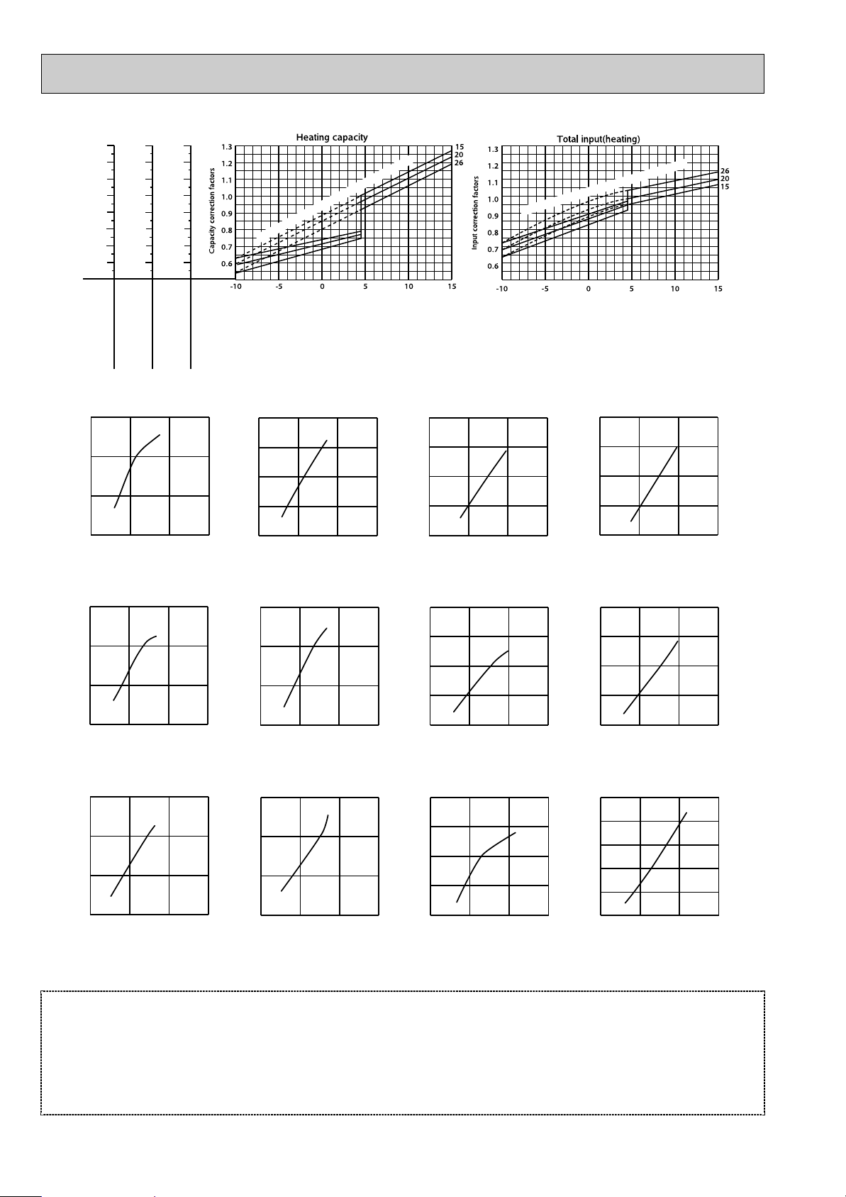
HEATING
(1) Indoor intake air dry-bulb temperature : D.B. ˚C
(2) Indoor outlet air dry-bulb temperature : D.B. ˚C
(3) Outdoor intake air wet-bulb temperature : W.B. ˚C
(4) Total input : W
How to measure the indoor air wet-bulb/dry-bulb temperature difference
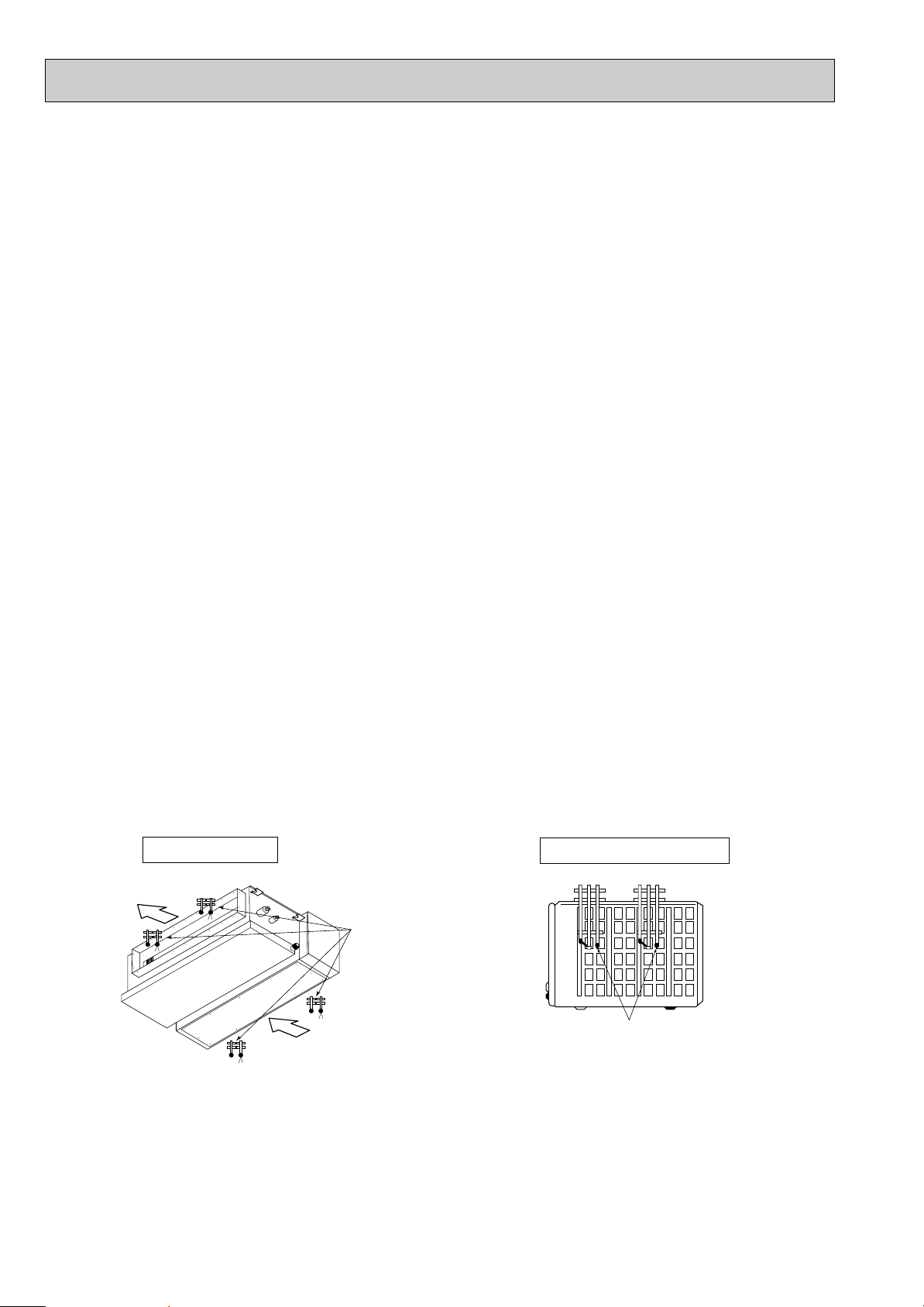
1. Attach at least 2 sets of wet-and-dry-bulb thermometers to the indoor air inlet as shown in the figure, and at least 2 sets of
wet-and-dry-bulb thermometers to the indoor air outlet. The thermometers must be attached to the position where air speed
is high.
2. Attach at least 2 sets of wet-and-dry-bulb thermometers to the outdoor air inlet.
Cover the thermometers to prevent direct rays of the sun.
3. Check that the air filter is cleaned.
4. Open windows and doors of the room.
5. Press the EMERGENCY OPERATION switch once to start the COOL(HEAT) MODE.
6. When system stabilizes after more than 15 minutes, measure temperature and take an average temperature.
7. 10 minutes later, measure temperature again and check that the temperature does not change.
INDOOR UNIT
OUTDOOR UNIT
19
Page 20
20.4
18.9
17.3
15.7
14.2
12.6
11.0
9.4
23.6
21.8
20.0
18.2
16.3
14.5
12.7
10.9
Indoor air Dry-bulb temperature
difference (degree)
Indoor intake air Dry-bulb temperature (
:)
Outdoor intake air Wet-bulb temperature (:)
Outdoor intake air Wet-bulb temperature (:)
Indoor intake air Dry-bulb temperature (:)
SUZ-A09VR.TH
Rated frequency 75Hz
SUZ-A12VR.TH
Rated frequency 76Hz
28.2
26.0
23.9
21.7
19.5
17.4
15.2
13.0
SUZ-A18VR.TH
Rated frequency 65Hz
NOTE:The above curves are for the heating operation without any frost.
0 50 100 150(Hz)
0.0
0.5
1.0
1.5
Correction of Cooling capacity
Capacity correction factors
The operational frequency of compressor
0 50 100 150(Hz)
0.0
0.5
1.0
1.5
Correction of Cooling capacity
Capacity correction factors
The operational frequency of compressor
Correction of Cooling total input
Input correction factors
The operational frequency of compressor
0 50 100 150(Hz)
0.0
0.5
1.0
1.5
2.0
1.5
1.0
0.5
0.0
0 50 100 150(Hz)
Correction of Heating capacity
Capacity correction factors
The operational frequency of compressor
2.0
1.5
1.0
0.5
0.0
Correction of
Heating total input
Input correction factors
The operational frequency of compressor
0 50 100 150(Hz)
2.0
1.5
1.0
0.5
0.0
0 50 100 150(Hz)
Correction of Heating capacity
Capacity correction factors
The operational frequency of compressor
Correction of Heating total input
The operational frequency of compressor
0 50 100 150(Hz)
2.0
1.5
1.0
0.5
0.0
Input correction factors
The operational frequency of compressor
Correction of Cooling total input
0 50 100 150(Hz)
2.0
1.5
1.0
0.5
0.0
Input correction factors
0 50 100 150(Hz)
0.0
0.5
1.0
1.5
Correction of Cooling capacity
Capacity correction factors
The operational frequency of compressor
Correction of Cooling total input
Input correction factors
The operational frequency of compressor
0 50 100 150(Hz)
0.0
0.5
1.0
1.5
2.5
2.0
1.5
1.0
0.5
0.0
Correction of
Heating total input
Input correction factors
The operational frequency of compressor
0 50 100 150(Hz)
2.0
1.5
1.0
0.5
0.0
0 50 100 150(Hz)
Correction of Heating capacity
Capacity correction factors
The operational frequency of compressor
SUZ-A09VR.TH
SUZ-A12VR.TH SUZ-A12VR.TH SUZ-A12VR.TH SUZ-A12VR.TH
SUZ-A09VR.TH SUZ-A09VR.TH SUZ-A09VR.TH
SUZ-A18VR.TH SUZ-A18VR.TH SUZ-A18VR.TH SUZ-A18VR.TH
OUTDOOR LOW PRESSURE AND OUTDOOR UNIT CURRENT
<How to operate fixed-frequency operation (Test run operation)>
1. Press the EMERGENCY OPERATION switch to COOL or HEAT mode.
2. Test run operation starts and continue to operate for 30 minutes.
3. Compressor starts at rated frequency in COOL mode or 58Hz in HEAT mode.
4. Indoor fan operates at High speed.
5. After 30 minutes, test run operation finishes and EMERGENCY OPERATION starts.
6. To cancel test run operation (EMERGENCY OPERATION), press the EMERGENCY OPERATION switch or any button on
remote controller.
NOTE : The unit of pressure has been changed to MPa on the international system of units (SI unit system).
The conversion factor is: 1(MPa [Gauge]) =10.2(kgf/ff[Gauge])
20
Page 21
Outdoor unit current(A)
15 2050256030
70 (%)
35(˚C)
2
2.5
3
3.5
4
57Hz
32
18
Ambient temperature(˚C) Ambient humidity(%)
SUZ-A12VR.TH
15 205025
60
30
70 (%)
35(˚C)
2
3
4
5
6
67Hz
32
18
Outdoor unit current(A)
Ambient temperature(˚C) Ambient humidity(%)
SUZ-A09VR.TH
(MPa [Gauge])
(kgf/F [Gauge])
18 32
15 2050256030
70 (%)
35(˚C)
0.2
0.4
0.6
0.8
1.0
1.2
57Hz
2
4
6
8
10
12
14
1.4
Ambient temperature(˚C) Ambient humidity(%)
Outdoor low pressure
SUZ-A09VR.TH
(MPa [Gauge])
(kgf/F [Gauge])
18 32
15 2050256030
70 (%)
35(˚C)
0.2
0.4
0.6
0.8
1.0
1.2
67Hz
1.4
Ambient temperature(˚C) Ambient humidity(%)
Outdoor low pressure
SUZ-A12VR.TH
2
4
6
8
10
12
14
Outdoor unit current(A)
15 2050256030
70 (%)
35(˚C)
5.0
6.0
7.0
8.0
9.0
75Hz
32
18
Ambient temperature(˚C) Ambient humidity(%)
SUZ-A18VR.TH
(MPa [Gauge])
(kgf/F [Gauge])
18 32
15 2050256030
70 (%)
35(˚C)
0.2
0.4
0.6
0.8
1.0
1.2
75Hz
1.4
Ambient temperature(˚C) Ambient humidity(%)
Outdoor low pressure
SUZ-A18VR.TH
2
4
6
8
10
12
14
OUTDOOR LOW PRESSURE AND OUTDOOR UNIT CURRENT
SUZ-A09VR.TH
Outdoor unit current (A)
Ambient temperature(˚C)
3.0
2.5
2.0
1.5
1.0
0.5
0.0
2 5 10 15 20 25(:)
58Hz
SUZ-A12VR.TH
Outdoor unit current (A)
Ambient temperature(˚C)
4.0
3.5
3.0
2.5
2.0
1.5
1.0
2 5 10 15 20 25(:)
58Hz
SUZ-A18VR.TH
Outdoor unit current (A)
Ambient temperature(˚C)
7.0
6.0
5.0
4.0
3.0
2.0
1.0
2 5 10 15 20 25(:)
58Hz
COOL operation
1 Both indoor and outdoor unit are under the
same temperature/humidity condition.
2 Air flow : High speed
3 Operational frequency : 57Hz(SUZ-A09VR.TH)
67Hz(SUZ-A12VR.TH)
75Hz(SUZ-A18VR.TH)
Dry-bulb temperature
20 50
25 60
30 70
Relative humidity(%)
HEAT operation
Condition indoor: Dry bulb temperature 20.0°C
Condition outdoor: Dry bulb temperature 2,7,15,20.0°C
Wet bulb temperature 14.5°C
Wet bulb temperature 1,6,12,14.5°C
21
Page 22
Air outlet
Air inlet
Wet-and dry-bulb
thermometers
Wet-and dry-bulb
thermometers
BACK VIEW
● SEZ-A09CR.W / SUZ-A09VR.TH
● SEZ-A12AR.TH / SUZ-A12VR.TH
● SEZ-A18AR.TH / SUZ-A18VR.TH
● SEZ-A24AR.TH / SUZ-A24VR.TH
The standard data contained in these specifications apply only to the operation of the air conditioner under normal condition.
Operating conditions vary according to the areas where these units are installed. The following information has been provided
to clarify the operating characteristics of the air conditioner under the conditions indicated by the performance curve.
(1) GUARANTEED VOLTAGE
Rated voltage : ±10% (207~253V), 50Hz
(2) AIR FLOW
Air flow should be set at MAX.
(3) MAIN READINGS
COOLING
(1) Indoor intake air wet-bulb temperature : W.B.˚C
(2) Indoor outlet air wet-bulb temperature : W.B.˚C
(3) Outdoor intake air dry-bulb temperature : D.B.˚C
(4) Total input : W
Indoor air wet/dry-bulb temperature difference on the side of the chart on page shows the difference between the
indoor intake air wet/dry-bulb temperature and the indoor outlet air wet/dry-bulb temperature for your reference at service.
HEATING
(1) Indoor intake air dry-bulb temperature : D.B.˚C
(2) Indoor outlet air dry-bulb temperature : D.B.˚C
(3) Outdoor intake air wet-bulb temperature : W.B.˚C
(4) Total input : W
How to measure the indoor air wet-bulb/dry-bulb temperature difference
1. Attach at least 2 sets of wet-and-dry-bulb thermometers to the indoor air inlet as shown in the figure, and at least 2 sets of
wet-and-dry-bulb thermometers to the indoor air outlet. The thermometers must be attached to the position where air speed
is high.
2. Attach at least 2 sets of wet-and-dry-bulb thermometers to the outdoor air inlet.
Cover the thermometers to prevent direct rays of the sun.
3. Check that the air filter is cleaned.
4. Open windows and doors of the room.
5. Press the TEST button twice to start the COOL(HEAT) MODE.
6. When system stabilizes after more than 15 minutes, measure temperature and take an average temperature.
7. 10 minutes later, measure temperature again and check that the temperature does not change.
INDOOR UNIT
OUTDOOR UNIT
w The picture is SEZ-A12,18, 24AR.
SEZ-A09CR is similar to SEZ-A12, 18, 24AR.
22
Page 23
NOTE:The above curves are for the heating operation without any frost.
Indoor air Wet-bulb temperature
difference (degree)
Indoor intake air Wet-bulb temperature (:)
Outdoor intake air Dry-bulb temperature (:)
Indoor intake air Wet-bulb temperature (
:)
Outdoor intake air Dry-bulb temperature (:)
7.9
7.4
6.8
6.2
5.7
5.1
SUZ-A09VR.TH
Rated frequency 57Hz
8.4
7.8
7.2
6.6
6.0
5.4
SUZ-A18VR.TH
Rated frequency 80Hz
7.8
7.2
6.7
6.1
5.6
5.0
SUZ-A12VR.TH
Rated frequency 67Hz
8.6
8.0
7.4
6.8
6.2
5.5
SUZ-A24VR.TH
Rated frequency 87Hz
25.2
23.2
21.3
19.4
17.4
15.5
13.6
11.6
Indoor air Dry-bulb temperature
difference (degree)
Indoor intake air Dry-bulb temperature (
:)
Outdoor intake air Wet-bulb temperature (:)
Outdoor intake air Wet-bulb temperature (:)
Indoor intake air Dry-bulb temperature (:)
SUZ-A09VR.TH
Rated frequency 75Hz
22.1
20.4
18.7
17.0
15.3
13.6
11.9
10.2
SUZ-A12VR.TH
Rated frequency 76Hz
24.5
22.6
20.7
18.9
17.0
15.1
13.2
11.3
SUZ-A18VR.TH
Rated frequency 80Hz
25.3
23.3
21.4
19.4
17.5
15.5
13.6
11.7
SUZ-A24VR.TH
Rated frequency 96Hz
23
Page 24
SUZ-A09VR.TH
SUZ-A09VR.TH SUZ-A09VR.TH SUZ-A09VR.TH
SUZ-A12VR.TH
SUZ-A12VR.TH SUZ-A12VR.TH SUZ-A12VR.TH
SUZ-A18VR.TH
SUZ-A18VR.TH SUZ-A18VR.TH SUZ-A18VR.TH
SUZ-A24VR.TH
SUZ-A24VR.TH SUZ-A24VR.TH SUZ-A24VR.TH
0 50 100 150(Hz)
0.0
0.5
1.0
1.5
Correction of Cooling capacity
Capacity correction factors
The operational frequency of compressor
Correction of Cooling total input
Input correction factors
The operational frequency of compressor
2.0
1.5
1.0
0.5
0.0
Correction of
Heating total input
Input correction factors
The operational frequency of compressor
0 50 100 150(Hz)
2.0
1.5
1.0
0.5
0.0
0 50 100 150(Hz)
2.0
1.5
1.0
0.5
0.0
0 50 100 150(Hz)
Correction of Heating capacity
Capacity correction factors
The operational frequency of compressor
0 50 100 150(Hz)
0.0
0.5
1.0
1.5
Correction of Cooling capacity
Capacity correction factors
The operational frequency of compressor
Correction of Cooling total input
Input correction factors
The operational frequency of compressor
0 50 100 150(Hz)
0.0
0.5
1.0
1.5
2.0
1.5
1.0
0.5
0.0
Correction of
Heating total input
Input correction factors
The operational frequency of compressor
0 50 100 150(Hz)
2.0
1.5
1.0
0.5
0.0
0 50 100 150(Hz)
Correction of Heating capacity
Capacity correction factors
The operational frequency of compressor
OUTDOOR LOW PRESSURE AND OUTDOOR UNIT CURRENT
<How to operate fixed-frequency operation (Test run operation)>
1. Press the TEST button to COOL or HEAT mode.
2. Test run operation starts and continue to operate for 30 minutes.
3. Compressor starts at rated frequency in COOL mode or 58Hz in HEAT mode.
4. Indoor fan operates at High speed.
5. After 30 minutes, test run operation finishes and EMERGENCY OPERATION starts.
6. To cancel test run operation (EMERGENCY OPERATION), press the ON/OFF button on remote controller.
NOTE : The unit of pressure has been changed to MPa on the international system of units (SI unit system).
The conversion factor is: 1(MPa [Gauge]) =10.2(kgf/ff[Gauge])
24
Page 25
OUTDOOR LOW PRESSURE AND OUTDOOR UNIT CURRENT
SUZ-A09VR.TH
Outdoor unit current (A)
Ambient temperature(˚C)
4.0
3.5
3.0
2.5
2.0
1.5
1.0
2 5 10 15 20 25(:)
58Hz
SUZ-A12VR.TH
Outdoor unit current (A)
Ambient temperature(˚C)
4.0
3.5
3.0
2.5
2.0
1.5
1.0
2 5 10 15 20 25(:)
58Hz
SUZ-A18VR.TH
Outdoor unit current (A)
Ambient temperature(˚C)
7.0
6.0
5.0
4.0
3.0
2.0
1.0
2 5 10 15 20 25(:)
58Hz
58Hz
SUZ-A24VR.TH
Outdoor unit current (A)
Ambient temperature(˚C)
7.0
6.0
5.0
4.0
3.0
2.0
1.0
2 5 10 15 20 25(:)
COOL operation
1 Both indoor and outdoor unit are under the
same temperature/humidity condition.
2 Air flow : High speed
3 Operational frequency : 57Hz(SUZ-A09VR.TH)
67Hz(SUZ-A12VR.TH)
80Hz(SUZ-A18VR.TH)
87Hz(SUZ-A24VR.TH)
Dry-bulb temperature
20
25
30 70
Relative humidity(%)
50
60
(kgf/F [Gauge])
14
12
10
8
6
Outdoor low pressure
4
2
Ambient temperature(˚C) Ambient humidity(%)
(MPa [Gauge])
1.4
1.2
1.0
0.8
0.6
0.4
0.2
15 2050256030
18 32
57Hz
70 (%)
SUZ-A09VR.TH
6
5
SUZ-A09VR.TH
60
57Hz
30
35(˚C)
32
70 (%)
4
3
Outdoor unit current(A)
2
15 205025
18
Ambient temperature(˚C) Ambient humidity(%)
SUZ-A12VR.TH
35(˚C)
(kgf/F [Gauge])
14
12
10
8
6
Outdoor low pressure
4
2
Ambient temperature(˚C) Ambient humidity(%)
(MPa [Gauge])
1.4
1.2
1.0
0.8
0.6
0.4
0.2
15 2050256030
18 32
SUZ-A12VR.TH
6
5
4
3
Outdoor unit current(A)
2
15 205025
18
Ambient temperature(˚C) Ambient humidity(%)
60
67Hz
35(˚C)
70 (%)
67Hz
30
35(˚C)
32
70 (%)
(kgf/F [Gauge])
14
12
10
8
6
Outdoor low pressure
4
2
Ambient temperature(˚C) Ambient humidity(%)
(MPa [Gauge])
1.4
1.2
1.0
0.8
0.6
0.4
0.2
15 2050256030
18 32
80Hz
70 (%)
SUZ-A18VR.TH
SUZ-A18VR.TH
10
9
8
7
Outdoor unit current(A)
6
15 205025
18
Ambient temperature(˚C) Ambient humidity(%)
60
80Hz
30
35(˚C)
32
70 (%)
SUZ-A24VR.TH
35(˚C)
(kgf/F [Gauge])
14
12
10
8
6
Outdoor low pressure
4
2
Ambient temperature(˚C) Ambient humidity(%)
(MPa [Gauge])
1.4
1.2
1.0
0.8
0.6
0.4
0.2
15 2050256030
18 32
SUZ-A24VR.TH
12
10
8
6
Outdoor unit current(A)
4
15 205025
18
Ambient temperature(˚C) Ambient humidity(%)
60
87Hz
35(˚C)
70 (%)
87Hz
30
35(˚C)
32
70 (%)
HEAT operation
Condition indoor: Dry bulb temperature 20.0°C
Condition outdoor: Dry bulb temperature 2,7,15,20.0°C
Wet bulb temperature 14.5°C
Wet bulb temperature 1,6,12,14.5°C
25
Page 26

OUTDOOR D.B.(;)
INDOOR INDOOR
21 25 27 30
D.B.(;) W.B.(;)
Q SHC SHF INPUT Q SHC SHF INPUT Q SHC SHF INPUT Q SHC SHF INPUT
21
21
22
22
22
23
23
23
24
24
24
24
25
25
25
26
26
26
26
26
27
27
27
27
27
28
28
28
28
28
29
29
29
29
29
30
30
30
30
30
31
31
31
31
31
32
32
32
32
32
18
20
18
20
22
18
20
22
18
20
22
24
20
22
24
18
20
22
24
26
18
20
22
24
26
18
20
22
24
26
18
20
22
24
26
18
20
22
24
26
18
20
22
24
26
18
20
22
24
26
2.94
3.06
2.94
3.06
3.19
2.94
3.06
3.19
2.94
3.06
3.19
3.35
3.06
3.19
3.35
2.94
3.06
3.19
3.35
3.45
2.94
3.06
3.19
3.35
3.45
2.94
3.06
3.19
3.35
3.45
2.94
3.06
3.19
3.35
3.45
2.94
3.06
3.19
3.35
3.45
2.94
3.06
3.19
3.35
3.45
2.94
3.06
3.19
3.35
3.45
0.67
0.55
0.71
0.59
0.47
0.75
0.63
0.51
0.79
0.67
0.55
0.43
0.71
0.59
0.47
0.87
0.75
0.63
0.51
0.39
0.91
0.79
0.67
0.55
0.43
0.95
0.83
0.71
0.59
0.47
0.99
0.87
0.75
0.63
0.51
1.03
0.91
0.79
0.67
0.55
1.07
0.95
0.83
0.71
0.59
1.11
0.99
0.87
0.75
0.63
608
638
608
638
661
608
638
661
608
638
661
692
638
661
692
608
638
661
692
730
608
638
661
692
730
608
638
661
692
730
608
638
661
692
730
608
638
661
692
730
608
638
661
692
730
608
638
661
692
730
1.97
1.68
2.09
1.81
1.50
2.20
1.93
1.63
2.32
2.05
1.75
1.44
2.17
1.88
1.57
2.56
2.30
2.01
1.71
1.35
2.67
2.42
2.14
1.84
1.48
2.79
2.54
2.26
1.98
1.62
2.91
2.66
2.39
2.11
1.76
3.03
2.79
2.52
2.24
1.90
3.14
2.91
2.65
2.38
2.04
3.26
3.03
2.77
2.51
2.17
2.81
2.94
2.81
2.94
3.08
2.81
2.94
3.08
2.81
2.94
3.08
3.23
2.94
3.08
3.23
2.81
2.94
3.08
3.23
3.35
2.81
2.94
3.08
3.23
3.35
2.81
2.94
3.08
3.23
3.35
2.81
2.94
3.08
3.23
3.35
2.81
2.94
3.08
3.23
3.35
2.81
2.94
3.08
3.23
3.35
2.81
2.94
3.08
3.23
3.35
0.67
0.55
0.71
0.59
0.47
0.75
0.63
0.51
0.79
0.67
0.55
0.43
0.71
0.59
0.47
0.87
0.75
0.63
0.51
0.39
0.91
0.79
0.67
0.55
0.43
0.95
0.83
0.71
0.59
0.47
0.99
0.87
0.75
0.63
0.51
1.03
0.91
0.79
0.67
0.55
1.07
0.95
0.83
0.71
0.59
1.11
0.99
0.87
0.75
0.63
638
676
638
676
703
638
676
703
638
676
703
730
676
703
730
638
676
703
730
768
638
676
703
730
768
638
676
703
730
768
638
676
703
730
768
638
676
703
730
768
638
676
703
730
768
638
676
703
730
768
1.88
1.62
2.00
1.73
1.45
2.11
1.85
1.57
2.22
1.97
1.69
1.39
2.09
1.81
1.52
2.45
2.20
1.94
1.64
1.31
2.56
2.32
2.06
1.77
1.44
2.67
2.44
2.18
1.90
1.57
2.78
2.56
2.31
2.03
1.71
2.90
2.67
2.43
2.16
1.84
3.01
2.79
2.55
2.29
1.98
3.12
2.91
2.68
2.42
2.11
2.70
2.85
2.70
2.85
3.00
2.70
2.85
3.00
2.70
2.85
3.00
3.15
2.85
3.00
3.15
2.70
2.85
3.00
3.15
3.30
2.70
2.85
3.00
3.15
3.30
2.70
2.85
3.00
3.15
3.30
2.70
2.85
3.00
3.15
3.30
2.70
2.85
3.00
3.15
3.30
2.70
2.85
3.00
3.15
3.30
2.70
2.85
3.00
3.15
3.30
0.67
0.55
0.71
0.59
0.47
0.75
0.63
0.51
0.79
0.67
0.55
0.43
0.71
0.59
0.47
0.87
0.75
0.63
0.51
0.39
0.91
0.79
0.67
0.55
0.43
0.95
0.83
0.71
0.59
0.47
0.99
0.87
0.75
0.63
0.51
1.03
0.91
0.79
0.67
0.55
1.07
0.95
0.83
0.71
0.59
1.11
0.99
0.87
0.75
0.63
669
692
669
692
722
669
692
722
669
692
722
752
692
722
752
669
692
722
752
790
669
692
722
752
790
669
692
722
752
790
669
692
722
752
790
669
692
722
752
790
669
692
722
752
790
669
692
722
752
790
1.81
1.57
1.92
1.68
1.41
2.03
1.80
1.53
2.13
1.91
1.65
1.35
2.02
1.77
1.48
2.35
2.14
1.89
1.61
1.29
2.46
2.25
2.01
1.73
1.42
2.57
2.37
2.13
1.86
1.55
2.67
2.48
2.25
1.98
1.68
2.78
2.59
2.37
2.11
1.82
2.89
2.71
2.49
2.24
1.95
3.00
2.82
2.61
2.36
2.08
2.60
2.75
2.60
2.75
2.88
2.60
2.75
2.88
2.60
2.75
2.88
3.05
2.75
2.88
3.05
2.60
2.75
2.88
3.05
3.20
2.60
2.75
2.88
3.05
3.20
2.60
2.75
2.88
3.05
3.20
2.60
2.75
2.88
3.05
3.20
2.60
2.75
2.88
3.05
3.20
2.60
2.75
2.88
3.05
3.20
2.60
2.75
2.88
3.05
3.20
0.67
0.55
0.71
0.59
0.47
0.75
0.63
0.51
0.79
0.67
0.55
0.43
0.71
0.59
0.47
0.87
0.75
0.63
0.51
0.39
0.91
0.79
0.67
0.55
0.43
0.95
0.83
0.71
0.59
0.47
0.99
0.87
0.75
0.63
0.51
1.03
0.91
0.79
0.67
0.55
1.07
0.95
0.83
0.71
0.59
1.11
0.99
0.87
0.75
0.63
699
722
699
722
752
699
722
752
699
722
752
790
722
752
790
699
722
752
790
813
699
722
752
790
813
699
722
752
790
813
699
722
752
790
813
699
722
752
790
813
699
722
752
790
813
699
722
752
790
813
1.74
1.51
1.85
1.62
1.35
1.95
1.73
1.47
2.05
1.84
1.58
1.31
1.95
1.70
1.43
2.26
2.06
1.81
1.56
1.25
2.37
2.17
1.93
1.68
1.38
2.47
2.28
2.04
1.80
1.50
2.57
2.39
2.16
1.92
1.63
2.68
2.50
2.27
2.04
1.76
2.78
2.61
2.39
2.17
1.89
2.89
2.72
2.50
2.29
2.02
PERFORMANCE DATA
COOLING operation Rated frequency 57Hz
SLZ-A09AR.TH / SUZ-A09VR.TH
CAPACITY : 2.5(kW) INPUT : 760(W) SHF : 0.85
NOTE Q : Total capacity (kW) SHF : Sensible heat factor DB : Dry-bulb temperature
SHC : Sensible heat capacity (kW) INPUT : Total power input (W) WB : Wet-bulb temperature
26
Page 27

PERFORMANCE DATA
COOLING operation Rated frequency 57Hz
SLZ-A09AR.TH / SUZ-A09VR.TH
CAPACITY : 2.5(kW) INPUT : 760(W) SHF : 0.85
OUTDOOR D.B.(;)
INDOOR INDOOR
D.B.(;) W.B.(;)
21
21
22
22
22
23
23
23
24
24
24
24
25
25
25
26
26
26
26
26
27
27
27
27
27
28
28
28
28
28
29
29
29
29
29
30
30
30
30
30
31
31
31
31
31
32
32
32
32
32
NOTE Q : Total capacity (kW) SHF : Sensible heat factor DB : Dry-bulb temperature
18
20
18
20
22
18
20
22
18
20
22
24
20
22
24
18
20
22
24
26
18
20
22
24
26
18
20
22
24
26
18
20
22
24
26
18
20
22
24
26
18
20
22
24
26
18
20
22
24
26
SHC : Sensible heat capacity (kW) INPUT : Total power input (W) WB : Wet-bulb temperature
Q SHC SHF INPUT Q SHC SHF INPUT Q SHC SHF INPUT
2.45
2.58
2.45
2.58
2.73
2.45
2.58
2.73
2.45
2.58
2.73
2.88
2.58
2.73
2.88
2.45
2.58
2.73
2.88
3.03
2.45
2.58
2.73
2.88
3.03
2.45
2.58
2.73
2.88
3.03
2.45
2.58
2.73
2.88
3.03
2.45
2.58
2.73
2.88
3.03
2.45
2.58
2.73
2.88
3.03
2.45
2.58
2.73
2.88
3.03
35 40 46
1.64
1.42
1.74
1.52
1.28
1.84
1.62
1.39
1.94
1.73
1.50
1.24
1.83
1.61
1.35
2.13
1.93
1.72
1.47
1.18
2.23
2.03
1.83
1.58
1.30
2.33
2.14
1.93
1.70
1.42
2.43
2.24
2.04
1.81
1.54
2.52
2.34
2.15
1.93
1.66
2.62
2.45
2.26
2.04
1.78
2.72
2.55
2.37
2.16
1.91
0.67
0.55
0.71
0.59
0.47
0.75
0.63
0.51
0.79
0.67
0.55
0.43
0.71
0.59
0.47
0.87
0.75
0.63
0.51
0.39
0.91
0.79
0.67
0.55
0.43
0.95
0.83
0.71
0.59
0.47
0.99
0.87
0.75
0.63
0.51
1.03
0.91
0.79
0.67
0.55
1.07
0.95
0.83
0.71
0.59
1.11
0.99
0.87
0.75
0.63
745
775
745
775
806
745
775
806
745
775
806
836
775
806
836
745
775
806
836
866
745
775
806
836
866
745
775
806
836
866
745
775
806
836
866
745
775
806
836
866
745
775
806
836
866
745
775
806
836
866
2.25
2.40
2.25
2.40
2.55
2.25
2.40
2.55
2.25
2.40
2.55
2.70
2.40
2.55
2.70
2.25
2.40
2.55
2.70
2.85
2.25
2.40
2.55
2.70
2.85
2.25
2.40
2.55
2.70
2.85
2.25
2.40
2.55
2.70
2.85
2.25
2.40
2.55
2.70
2.85
2.25
2.40
2.55
2.70
2.85
2.25
2.40
2.55
2.70
2.85
1.51
1.32
1.60
1.42
1.20
1.69
1.51
1.30
1.78
1.61
1.40
1.16
1.70
1.50
1.27
1.96
1.80
1.61
1.38
1.11
2.05
1.90
1.71
1.49
1.23
2.14
1.99
1.81
1.59
1.34
2.23
2.09
1.91
1.70
1.45
2.32
2.18
2.01
1.81
1.57
2.41
2.28
2.12
1.92
1.68
2.50
2.38
2.22
2.03
1.80
0.67
0.55
0.71
0.59
0.47
0.75
0.63
0.51
0.79
0.67
0.55
0.43
0.71
0.59
0.47
0.87
0.75
0.63
0.51
0.39
0.91
0.79
0.67
0.55
0.43
0.95
0.83
0.71
0.59
0.47
0.99
0.87
0.75
0.63
0.51
1.03
0.91
0.79
0.67
0.55
1.07
0.95
0.83
0.71
0.59
1.11
0.99
0.87
0.75
0.63
790
813
790
813
851
790
813
851
790
813
851
874
813
851
874
790
813
851
874
904
790
813
851
874
904
790
813
851
874
904
790
813
851
874
904
790
813
851
874
904
790
813
851
874
904
790
813
851
874
904
2.08
2.23
2.08
2.23
2.38
2.08
2.23
2.38
2.08
2.23
2.38
2.55
2.23
2.38
2.55
2.08
2.23
2.38
2.55
2.68
2.08
2.23
2.38
2.55
2.68
2.08
2.23
2.38
2.55
2.68
2.08
2.23
2.38
2.55
2.68
2.08
2.23
2.38
2.55
2.68
2.08
2.23
2.38
2.55
2.68
2.08
2.23
2.38
2.55
2.68
1.39
1.22
1.47
1.31
1.12
1.56
1.40
1.21
1.64
1.49
1.31
1.10
1.58
1.40
1.20
1.81
1.67
1.50
1.30
1.04
1.89
1.76
1.59
1.40
1.15
1.97
1.85
1.69
1.50
1.26
2.05
1.94
1.78
1.61
1.36
2.14
2.02
1.88
1.71
1.47
2.22
2.11
1.97
1.81
1.58
2.30
2.20
2.07
1.91
1.69
0.67
0.55
0.71
0.59
0.47
0.75
0.63
0.51
0.79
0.67
0.55
0.43
0.71
0.59
0.47
0.87
0.75
0.63
0.51
0.39
0.91
0.79
0.67
0.55
0.43
0.95
0.83
0.71
0.59
0.47
0.99
0.87
0.75
0.63
0.51
1.03
0.91
0.79
0.67
0.55
1.07
0.95
0.83
0.71
0.59
1.11
0.99
0.87
0.75
0.63
821
859
821
859
882
821
859
882
821
859
882
912
859
882
912
821
859
882
912
942
821
859
882
912
942
821
859
882
912
942
821
859
882
912
942
821
859
882
912
942
821
859
882
912
942
821
859
882
912
942
27
Page 28

OUTDOOR D.B.(;)
INDOOR INDOOR
21 25 27 30
D.B.(;) W.B.(;)
Q SHC SHF INPUT Q SHC SHF INPUT Q SHC SHF INPUT Q SHC SHF INPUT
21
21
22
22
22
23
23
23
24
24
24
24
25
25
25
26
26
26
26
26
27
27
27
27
27
28
28
28
28
28
29
29
29
29
29
30
30
30
30
30
31
31
31
31
31
32
32
32
32
32
18
20
18
20
22
18
20
22
18
20
22
24
20
22
24
18
20
22
24
26
18
20
22
24
26
18
20
22
24
26
18
20
22
24
26
18
20
22
24
26
18
20
22
24
26
18
20
22
24
26
3.76
3.92
3.76
3.92
4.08
3.76
3.92
4.08
3.76
3.92
4.08
4.29
3.92
4.08
4.29
3.76
3.92
4.08
4.29
4.42
3.76
3.92
4.08
4.29
4.42
3.76
3.92
4.08
4.29
4.42
3.76
3.92
4.08
4.29
4.42
3.76
3.92
4.08
4.29
4.42
3.76
3.92
4.08
4.29
4.42
3.76
3.92
4.08
4.29
4.42
0.61
0.49
0.65
0.53
0.41
0.69
0.57
0.45
0.73
0.61
0.49
0.37
0.65
0.53
0.41
0.81
0.69
0.57
0.45
0.33
0.85
0.73
0.61
0.49
0.37
0.89
0.77
0.65
0.53
0.41
0.93
0.81
0.69
0.57
0.45
0.97
0.85
0.73
0.61
0.49
1.01
0.89
0.77
0.65
0.53
1.05
0.93
0.81
0.69
0.57
848
890
848
890
922
848
890
922
848
890
922
965
890
922
965
848
890
922
965
1018
848
890
922
965
1018
848
890
922
965
1018
848
890
922
965
1018
848
890
922
965
1018
848
890
922
965
1018
848
890
922
965
1018
2.29
1.92
2.44
2.08
1.67
2.59
2.23
1.84
2.74
2.39
2.00
1.59
2.55
2.16
1.76
3.05
2.70
2.33
1.93
1.46
3.20
2.86
2.49
2.10
1.63
3.35
3.02
2.65
2.27
1.81
3.50
3.18
2.82
2.44
1.99
3.65
3.33
2.98
2.62
2.16
3.80
3.49
3.14
2.79
2.34
3.95
3.65
3.30
2.96
2.52
3.60
3.76
3.60
3.76
3.94
3.60
3.76
3.94
3.60
3.76
3.94
4.13
3.76
3.94
4.13
3.60
3.76
3.94
4.13
4.29
3.60
3.76
3.94
4.13
4.29
3.60
3.76
3.94
4.13
4.29
3.60
3.76
3.94
4.13
4.29
3.60
3.76
3.94
4.13
4.29
3.60
3.76
3.94
4.13
4.29
3.60
3.76
3.94
4.13
4.29
0.61
0.49
0.65
0.53
0.41
0.69
0.57
0.45
0.73
0.61
0.49
0.37
0.65
0.53
0.41
0.81
0.69
0.57
0.45
0.33
0.85
0.73
0.61
0.49
0.37
0.89
0.77
0.65
0.53
0.41
0.93
0.81
0.69
0.57
0.45
0.97
0.85
0.73
0.61
0.49
1.01
0.89
0.77
0.65
0.53
1.05
0.93
0.81
0.69
0.57
890
943
890
943
981
890
943
981
890
943
981
1018
943
981
1018
890
943
981
1018
1071
890
943
981
1018
1071
890
943
981
1018
1071
890
943
981
1018
1071
890
943
981
1018
1071
890
943
981
1018
1071
890
943
981
1018
1071
2.20
1.84
2.34
1.99
1.61
2.48
2.14
1.77
2.63
2.29
1.93
1.53
2.44
2.09
1.69
2.92
2.59
2.24
1.86
1.42
3.06
2.74
2.40
2.02
1.59
3.20
2.90
2.56
2.19
1.76
3.35
3.05
2.72
2.35
1.93
3.49
3.20
2.87
2.52
2.10
3.64
3.35
3.03
2.68
2.27
3.78
3.50
3.19
2.85
2.44
3.46
3.65
3.46
3.65
3.84
3.46
3.65
3.84
3.46
3.65
3.84
4.03
3.65
3.84
4.03
3.46
3.65
3.84
4.03
4.22
3.46
3.65
3.84
4.03
4.22
3.46
3.65
3.84
4.03
4.22
3.46
3.65
3.84
4.03
4.22
3.46
3.65
3.84
4.03
4.22
3.46
3.65
3.84
4.03
4.22
3.46
3.65
3.84
4.03
4.22
0.61
0.49
0.65
0.53
0.41
0.69
0.57
0.45
0.73
0.61
0.49
0.37
0.65
0.53
0.41
0.81
0.69
0.57
0.45
0.33
0.85
0.73
0.61
0.49
0.37
0.89
0.77
0.65
0.53
0.41
0.93
0.81
0.69
0.57
0.45
0.97
0.85
0.73
0.61
0.49
1.01
0.89
0.77
0.65
0.53
1.05
0.93
0.81
0.69
0.57
933
965
933
965
1007
933
965
1007
933
965
1007
1049
965
1007
1049
933
965
1007
1049
1102
933
965
1007
1049
1102
933
965
1007
1049
1102
933
965
1007
1049
1102
933
965
1007
1049
1102
933
965
1007
1049
1102
933
965
1007
1049
1102
2.11
1.79
2.25
1.93
1.57
2.38
2.08
1.73
2.52
2.23
1.88
1.49
2.37
2.04
1.65
2.80
2.52
2.19
1.81
1.39
2.94
2.66
2.34
1.98
1.56
3.08
2.81
2.50
2.14
1.73
3.21
2.95
2.65
2.30
1.90
3.35
3.10
2.80
2.46
2.07
3.49
3.25
2.96
2.62
2.24
3.63
3.39
3.11
2.78
2.41
3.33
3.52
3.33
3.52
3.68
3.33
3.52
3.68
3.33
3.52
3.68
3.90
3.52
3.68
3.90
3.33
3.52
3.68
3.90
4.10
3.33
3.52
3.68
3.90
4.10
3.33
3.52
3.68
3.90
4.10
3.33
3.52
3.68
3.90
4.10
3.33
3.52
3.68
3.90
4.10
3.33
3.52
3.68
3.90
4.10
3.33
3.52
3.68
3.90
4.10
0.61
0.49
0.65
0.53
0.41
0.69
0.57
0.45
0.73
0.61
0.49
0.37
0.65
0.53
0.41
0.81
0.69
0.57
0.45
0.33
0.85
0.73
0.61
0.49
0.37
0.89
0.77
0.65
0.53
0.41
0.93
0.81
0.69
0.57
0.45
0.97
0.85
0.73
0.61
0.49
1.01
0.89
0.77
0.65
0.53
1.05
0.93
0.81
0.69
0.57
975
1007
975
1007
1049
975
1007
1049
975
1007
1049
1102
1007
1049
1102
975
1007
1049
1102
1134
975
1007
1049
1102
1134
975
1007
1049
1102
1134
975
1007
1049
1102
1134
975
1007
1049
1102
1134
975
1007
1049
1102
1134
975
1007
1049
1102
1134
2.03
1.72
2.16
1.87
1.51
2.30
2.01
1.66
2.43
2.15
1.80
1.44
2.29
1.95
1.60
2.70
2.43
2.10
1.76
1.35
2.83
2.57
2.24
1.91
1.52
2.96
2.71
2.39
2.07
1.68
3.10
2.85
2.54
2.23
1.84
3.23
2.99
2.69
2.38
2.01
3.36
3.13
2.83
2.54
2.17
3.49
3.27
2.98
2.69
2.33
PERFORMANCE DATA
COOLING operation Rated frequency 67Hz
SLZ-A12AR.TH / SUZ-A12VR.TH
CAPACITY : 3.2(kW) INPUT : 1060(W) SHF : 0.79
NOTE Q : Total capacity (kW) SHF : Sensible heat factor DB : Dry-bulb temperature
SHC : Sensible heat capacity (kW) INPUT : Total power input (W) WB : Wet-bulb temperature
28
Page 29

PERFORMANCE DATA
COOLING operation Rated frequency 67Hz
SLZ-A12AR.TH / SUZ-A12VR.TH
CAPACITY : 3.2(kW) INPUT : 1060(W) SHF : 0.79
OUTDOOR D.B.(;)
INDOOR INDOOR
D.B.(;) W.B.(;)
21
21
22
22
22
23
23
23
24
24
24
24
25
25
25
26
26
26
26
26
27
27
27
27
27
28
28
28
28
28
29
29
29
29
29
30
30
30
30
30
31
31
31
31
31
32
32
32
32
32
NOTE Q : Total capacity (kW) SHF : Sensible heat factor DB : Dry-bulb temperature
18
20
18
20
22
18
20
22
18
20
22
24
20
22
24
18
20
22
24
26
18
20
22
24
26
18
20
22
24
26
18
20
22
24
26
18
20
22
24
26
18
20
22
24
26
18
20
22
24
26
SHC : Sensible heat capacity (kW) INPUT : Total power input (W) WB : Wet-bulb temperature
Q SHC SHF INPUT Q SHC SHF INPUT Q SHC SHF INPUT
3.14
3.30
3.14
3.30
3.49
3.14
3.30
3.49
3.14
3.30
3.49
3.68
3.30
3.49
3.68
3.14
3.30
3.49
3.68
3.87
3.14
3.30
3.49
3.68
3.87
3.14
3.30
3.49
3.68
3.87
3.14
3.30
3.49
3.68
3.87
3.14
3.30
3.49
3.68
3.87
3.14
3.30
3.49
3.68
3.87
3.14
3.30
3.49
3.68
3.87
35 40 46
1.91
1.62
2.04
1.75
1.43
2.16
1.88
1.57
2.29
2.01
1.71
1.36
2.14
1.85
1.51
2.54
2.27
1.99
1.66
1.28
2.67
2.41
2.13
1.80
1.43
2.79
2.54
2.27
1.95
1.59
2.92
2.67
2.41
2.10
1.74
3.04
2.80
2.55
2.24
1.90
3.17
2.93
2.69
2.39
2.05
3.29
3.07
2.83
2.54
2.21
0.61
0.49
0.65
0.53
0.41
0.69
0.57
0.45
0.73
0.61
0.49
0.37
0.65
0.53
0.41
0.81
0.69
0.57
0.45
0.33
0.85
0.73
0.61
0.49
0.37
0.89
0.77
0.65
0.53
0.41
0.93
0.81
0.69
0.57
0.45
0.97
0.85
0.73
0.61
0.49
1.01
0.89
0.77
0.65
0.53
1.05
0.93
0.81
0.69
0.57
1039
1081
1039
1081
1124
1039
1081
1124
1039
1081
1124
1166
1081
1124
1166
1039
1081
1124
1166
1208
1039
1081
1124
1166
1208
1039
1081
1124
1166
1208
1039
1081
1124
1166
1208
1039
1081
1124
1166
1208
1039
1081
1124
1166
1208
1039
1081
1124
1166
1208
2.88
3.07
2.88
3.07
3.26
2.88
3.07
3.26
2.88
3.07
3.26
3.46
3.07
3.26
3.46
2.88
3.07
3.26
3.46
3.65
2.88
3.07
3.26
3.46
3.65
2.88
3.07
3.26
3.46
3.65
2.88
3.07
3.26
3.46
3.65
2.88
3.07
3.26
3.46
3.65
2.88
3.07
3.26
3.46
3.65
2.88
3.07
3.26
3.46
3.65
1.76
1.51
1.87
1.63
1.34
1.99
1.75
1.47
2.10
1.87
1.60
1.28
2.00
1.73
1.42
2.33
2.12
1.86
1.56
1.20
2.45
2.24
1.99
1.69
1.35
2.56
2.37
2.12
1.83
1.50
2.68
2.49
2.25
1.97
1.64
2.79
2.61
2.38
2.11
1.79
2.91
2.73
2.51
2.25
1.93
3.02
2.86
2.64
2.38
2.08
0.61
0.49
0.65
0.53
0.41
0.69
0.57
0.45
0.73
0.61
0.49
0.37
0.65
0.53
0.41
0.81
0.69
0.57
0.45
0.33
0.85
0.73
0.61
0.49
0.37
0.89
0.77
0.65
0.53
0.41
0.93
0.81
0.69
0.57
0.45
0.97
0.85
0.73
0.61
0.49
1.01
0.89
0.77
0.65
0.53
1.05
0.93
0.81
0.69
0.57
1102
1134
1102
1134
1187
1102
1134
1187
1102
1134
1187
1219
1134
1187
1219
1102
1134
1187
1219
1261
1102
1134
1187
1219
1261
1102
1134
1187
1219
1261
1102
1134
1187
1219
1261
1102
1134
1187
1219
1261
1102
1134
1187
1219
1261
1102
1134
1187
1219
1261
2.66
2.85
2.66
2.85
3.04
2.66
2.85
3.04
2.66
2.85
3.04
3.26
2.85
3.04
3.26
2.66
2.85
3.04
3.26
3.42
2.66
2.85
3.04
3.26
3.42
2.66
2.85
3.04
3.26
3.42
2.66
2.85
3.04
3.26
3.42
2.66
2.85
3.04
3.26
3.42
2.66
2.85
3.04
3.26
3.42
2.66
2.85
3.04
3.26
3.42
1.62
1.40
1.73
1.51
1.25
1.83
1.62
1.37
1.94
1.74
1.49
1.21
1.85
1.61
1.34
2.15
1.97
1.73
1.47
1.13
2.26
2.08
1.85
1.60
1.27
2.36
2.19
1.98
1.73
1.40
2.47
2.31
2.10
1.86
1.54
2.58
2.42
2.22
1.99
1.68
2.68
2.53
2.34
2.12
1.81
2.79
2.65
2.46
2.25
1.95
0.61
0.49
0.65
0.53
0.41
0.69
0.57
0.45
0.73
0.61
0.49
0.37
0.65
0.53
0.41
0.81
0.69
0.57
0.45
0.33
0.85
0.73
0.61
0.49
0.37
0.89
0.77
0.65
0.53
0.41
0.93
0.81
0.69
0.57
0.45
0.97
0.85
0.73
0.61
0.49
1.01
0.89
0.77
0.65
0.53
1.05
0.93
0.81
0.69
0.57
1145
1198
1145
1198
1230
1145
1198
1230
1145
1198
1230
1272
1198
1230
1272
1145
1198
1230
1272
1314
1145
1198
1230
1272
1314
1145
1198
1230
1272
1314
1145
1198
1230
1272
1314
1145
1198
1230
1272
1314
1145
1198
1230
1272
1314
1145
1198
1230
1272
1314
29
Page 30

OUTDOOR D.B.(;)
INDOOR INDOOR
21 25 27 30
D.B.(;) W.B.(;)
Q SHC SHF INPUT Q SHC SHF INPUT Q SHC SHF INPUT Q SHC SHF INPUT
21
21
22
22
22
23
23
23
24
24
24
24
25
25
25
26
26
26
26
26
27
27
27
27
27
28
28
28
28
28
29
29
29
29
29
30
30
30
30
30
31
31
31
31
31
32
32
32
32
32
18
20
18
20
22
18
20
22
18
20
22
24
20
22
24
18
20
22
24
26
18
20
22
24
26
18
20
22
24
26
18
20
22
24
26
18
20
22
24
26
18
20
22
24
26
18
20
22
24
26
5.41
5.64
5.41
5.64
5.87
5.41
5.64
5.87
5.41
5.64
5.87
6.16
5.64
5.87
6.16
5.41
5.64
5.87
6.16
6.35
5.41
5.64
5.87
6.16
6.35
5.41
5.64
5.87
6.16
6.35
5.41
5.64
5.87
6.16
6.35
5.41
5.64
5.87
6.16
6.35
5.41
5.64
5.87
6.16
6.35
5.41
5.64
5.87
6.16
6.35
0.50
0.38
0.54
0.42
0.30
0.58
0.46
0.34
0.62
0.50
0.38
0.26
0.54
0.42
0.30
0.70
0.58
0.46
0.34
0.22
0.74
0.62
0.50
0.38
0.26
0.78
0.66
0.54
0.42
0.30
0.82
0.70
0.58
0.46
0.34
0.86
0.74
0.62
0.50
0.38
0.90
0.78
0.66
0.54
0.42
0.94
0.82
0.70
0.58
0.46
1304
1369
1304
1369
1418
1304
1369
1418
1304
1369
1418
1483
1369
1418
1483
1304
1369
1418
1483
1565
1304
1369
1418
1483
1565
1304
1369
1418
1483
1565
1304
1369
1418
1483
1565
1304
1369
1418
1483
1565
1304
1369
1418
1483
1565
1304
1369
1418
1483
1565
2.70
2.14
2.92
2.37
1.76
3.13
2.59
1.99
3.35
2.82
2.23
1.60
3.04
2.46
1.85
3.78
3.27
2.70
2.10
1.40
4.00
3.49
2.93
2.34
1.65
4.22
3.72
3.17
2.59
1.90
4.43
3.94
3.40
2.84
2.16
4.65
4.17
3.64
3.08
2.41
4.86
4.40
3.87
3.33
2.67
5.08
4.62
4.11
3.58
2.92
5.18
5.41
5.18
5.41
5.66
5.18
5.41
5.66
5.18
5.41
5.66
5.93
5.41
5.66
5.93
5.18
5.41
5.66
5.93
6.16
5.18
5.41
5.66
5.93
6.16
5.18
5.41
5.66
5.93
6.16
5.18
5.41
5.66
5.93
6.16
5.18
5.41
5.66
5.93
6.16
5.18
5.41
5.66
5.93
6.16
5.18
5.41
5.66
5.93
6.16
0.50
0.38
0.54
0.42
0.30
0.58
0.46
0.34
0.62
0.50
0.38
0.26
0.54
0.42
0.30
0.70
0.58
0.46
0.34
0.22
0.74
0.62
0.50
0.38
0.26
0.78
0.66
0.54
0.42
0.30
0.82
0.70
0.58
0.46
0.34
0.86
0.74
0.62
0.50
0.38
0.90
0.78
0.66
0.54
0.42
0.94
0.82
0.70
0.58
0.46
1369
1451
1369
1451
1508
1369
1451
1508
1369
1451
1508
1565
1451
1508
1565
1369
1451
1508
1565
1646
1369
1451
1508
1565
1646
1369
1451
1508
1565
1646
1369
1451
1508
1565
1646
1369
1451
1508
1565
1646
1369
1451
1508
1565
1646
1369
1451
1508
1565
1646
2.59
2.05
2.79
2.27
1.70
3.00
2.49
1.92
3.21
2.70
2.15
1.54
2.92
2.38
1.78
3.62
3.13
2.60
2.02
1.36
3.83
3.35
2.83
2.25
1.60
4.04
3.57
3.06
2.49
1.85
4.24
3.78
3.28
2.73
2.10
4.45
4.00
3.51
2.97
2.34
4.66
4.22
3.73
3.20
2.59
4.86
4.43
3.96
3.44
2.84
4.97
5.24
4.97
5.24
5.52
4.97
5.24
5.52
4.97
5.24
5.52
5.80
5.24
5.52
5.80
4.97
5.24
5.52
5.80
6.07
4.97
5.24
5.52
5.80
6.07
4.97
5.24
5.52
5.80
6.07
4.97
5.24
5.52
5.80
6.07
4.97
5.24
5.52
5.80
6.07
4.97
5.24
5.52
5.80
6.07
4.97
5.24
5.52
5.80
6.07
0.50
0.38
0.54
0.42
0.30
0.58
0.46
0.34
0.62
0.50
0.38
0.26
0.54
0.42
0.30
0.70
0.58
0.46
0.34
0.22
0.74
0.62
0.50
0.38
0.26
0.78
0.66
0.54
0.42
0.30
0.82
0.70
0.58
0.46
0.34
0.86
0.74
0.62
0.50
0.38
0.90
0.78
0.66
0.54
0.42
0.94
0.82
0.70
0.58
0.46
1434
1483
1434
1483
1549
1434
1483
1549
1434
1483
1549
1614
1483
1549
1614
1434
1483
1549
1614
1695
1434
1483
1549
1614
1695
1434
1483
1549
1614
1695
1434
1483
1549
1614
1695
1434
1483
1549
1614
1695
1434
1483
1549
1614
1695
1434
1483
1549
1614
1695
2.48
1.99
2.68
2.20
1.66
2.88
2.41
1.88
3.08
2.62
2.10
1.51
2.83
2.32
1.74
3.48
3.04
2.54
1.97
1.34
3.68
3.25
2.76
2.20
1.58
3.88
3.46
2.98
2.43
1.82
4.07
3.67
3.20
2.67
2.06
4.27
3.88
3.42
2.90
2.31
4.47
4.09
3.64
3.13
2.55
4.67
4.30
3.86
3.36
2.79
4.78
5.06
4.78
5.06
5.29
4.78
5.06
5.29
4.78
5.06
5.29
5.61
5.06
5.29
5.61
4.78
5.06
5.29
5.61
5.89
4.78
5.06
5.29
5.61
5.89
4.78
5.06
5.29
5.61
5.89
4.78
5.06
5.29
5.61
5.89
4.78
5.06
5.29
5.61
5.89
4.78
5.06
5.29
5.61
5.89
4.78
5.06
5.29
5.61
5.89
0.50
0.38
0.54
0.42
0.30
0.58
0.46
0.34
0.62
0.50
0.38
0.26
0.54
0.42
0.30
0.70
0.58
0.46
0.34
0.22
0.74
0.62
0.50
0.38
0.26
0.78
0.66
0.54
0.42
0.30
0.82
0.70
0.58
0.46
0.34
0.86
0.74
0.62
0.50
0.38
0.90
0.78
0.66
0.54
0.42
0.94
0.82
0.70
0.58
0.46
1500
1549
1500
1549
1614
1500
1549
1614
1500
1549
1614
1695
1549
1614
1695
1500
1549
1614
1695
1744
1500
1549
1614
1695
1744
1500
1549
1614
1695
1744
1500
1549
1614
1695
1744
1500
1549
1614
1695
1744
1500
1549
1614
1695
1744
1500
1549
1614
1695
1744
2.39
1.92
2.58
2.13
1.59
2.77
2.33
1.80
2.97
2.53
2.01
1.46
2.73
2.22
1.68
3.35
2.93
2.43
1.91
1.30
3.54
3.14
2.65
2.13
1.53
3.73
3.34
2.86
2.36
1.77
3.92
3.54
3.07
2.58
2.00
4.11
3.74
3.28
2.81
2.24
4.31
3.95
3.49
3.03
2.47
4.50
4.15
3.70
3.25
2.71
PERFORMANCE DATA
COOLING operation Rated frequency 65Hz
SLZ-A18AR.TH / SUZ-A18VR.TH
CAPACITY : 4.6(kW) INPUT : 1630(W) SHF : 0.68
30
Page 31

OUTDOOR D.B.(;)
INDOOR INDOOR
35 40 46
D.B.(;) W.B.(;)
Q SHC SHF INPUT Q SHC SHF INPUT Q SHC SHF INPUT
21
21
22
22
22
23
23
23
24
24
24
24
25
25
25
26
26
26
26
26
27
27
27
27
27
28
28
28
28
28
29
29
29
29
29
30
30
30
30
30
31
31
31
31
31
32
32
32
32
32
18
20
18
20
22
18
20
22
18
20
22
24
20
22
24
18
20
22
24
26
18
20
22
24
26
18
20
22
24
26
18
20
22
24
26
18
20
22
24
26
18
20
22
24
26
18
20
22
24
26
4.51
4.74
4.51
4.74
5.01
4.51
4.74
5.01
4.51
4.74
5.01
5.29
4.74
5.01
5.29
4.51
4.74
5.01
5.29
5.57
4.51
4.74
5.01
5.29
5.57
4.51
4.74
5.01
5.29
5.57
4.51
4.74
5.01
5.29
5.57
4.51
4.74
5.01
5.29
5.57
4.51
4.74
5.01
5.29
5.57
4.51
4.74
5.01
5.29
5.57
0.50
0.38
0.54
0.42
0.30
0.58
0.46
0.34
0.62
0.50
0.38
0.26
0.54
0.42
0.30
0.70
0.58
0.46
0.34
0.22
0.74
0.62
0.50
0.38
0.26
0.78
0.66
0.54
0.42
0.30
0.82
0.70
0.58
0.46
0.34
0.86
0.74
0.62
0.50
0.38
0.90
0.78
0.66
0.54
0.42
0.94
0.82
0.70
0.58
0.46
1597
1663
1597
1663
1728
1597
1663
1728
1597
1663
1728
1793
1663
1728
1793
1597
1663
1728
1793
1858
1597
1663
1728
1793
1858
1597
1663
1728
1793
1858
1597
1663
1728
1793
1858
1597
1663
1728
1793
1858
1597
1663
1728
1793
1858
1597
1663
1728
1793
1858
2.25
1.80
2.43
1.99
1.50
2.61
2.18
1.70
2.79
2.37
1.91
1.38
2.56
2.11
1.59
3.16
2.75
2.31
1.80
1.22
3.34
2.94
2.51
2.01
1.45
3.52
3.13
2.71
2.22
1.67
3.70
3.32
2.91
2.43
1.89
3.88
3.51
3.11
2.65
2.12
4.06
3.70
3.31
2.86
2.34
4.24
3.89
3.51
3.07
2.56
4.14
4.42
4.14
4.42
4.69
4.14
4.42
4.69
4.14
4.42
4.69
4.97
4.42
4.69
4.97
4.14
4.42
4.69
4.97
5.24
4.14
4.42
4.69
4.97
5.24
4.14
4.42
4.69
4.97
5.24
4.14
4.42
4.69
4.97
5.24
4.14
4.42
4.69
4.97
5.24
4.14
4.42
4.69
4.97
5.24
4.14
4.42
4.69
4.97
5.24
0.50
0.38
0.54
0.42
0.30
0.58
0.46
0.34
0.62
0.50
0.38
0.26
0.54
0.42
0.30
0.70
0.58
0.46
0.34
0.22
0.74
0.62
0.50
0.38
0.26
0.78
0.66
0.54
0.42
0.30
0.82
0.70
0.58
0.46
0.34
0.86
0.74
0.62
0.50
0.38
0.90
0.78
0.66
0.54
0.42
0.94
0.82
0.70
0.58
0.46
1695
1744
1695
1744
1826
1695
1744
1826
1695
1744
1826
1875
1744
1826
1875
1695
1744
1826
1875
1940
1695
1744
1826
1875
1940
1695
1744
1826
1875
1940
1695
1744
1826
1875
1940
1695
1744
1826
1875
1940
1695
1744
1826
1875
1940
1695
1744
1826
1875
1940
2.07
1.68
2.24
1.85
1.41
2.40
2.03
1.60
2.57
2.21
1.78
1.29
2.38
1.97
1.49
2.90
2.56
2.16
1.69
1.15
3.06
2.74
2.35
1.89
1.36
3.23
2.91
2.53
2.09
1.57
3.39
3.09
2.72
2.29
1.78
3.56
3.27
2.91
2.48
1.99
3.73
3.44
3.10
2.68
2.20
3.89
3.62
3.28
2.88
2.41
3.82
4.09
3.82
4.09
4.37
3.82
4.09
4.37
3.82
4.09
4.37
4.69
4.09
4.37
4.69
3.82
4.09
4.37
4.69
4.92
3.82
4.09
4.37
4.69
4.92
3.82
4.09
4.37
4.69
4.92
3.82
4.09
4.37
4.69
4.92
3.82
4.09
4.37
4.69
4.92
3.82
4.09
4.37
4.69
4.92
3.82
4.09
4.37
4.69
4.92
0.50
0.38
0.54
0.42
0.30
0.58
0.46
0.34
0.62
0.50
0.38
0.26
0.54
0.42
0.30
0.70
0.58
0.46
0.34
0.22
0.74
0.62
0.50
0.38
0.26
0.78
0.66
0.54
0.42
0.30
0.82
0.70
0.58
0.46
0.34
0.86
0.74
0.62
0.50
0.38
0.90
0.78
0.66
0.54
0.42
0.94
0.82
0.70
0.58
0.46
1760
1842
1760
1842
1891
1760
1842
1891
1760
1842
1891
1956
1842
1891
1956
1760
1842
1891
1956
2021
1760
1842
1891
1956
2021
1760
1842
1891
1956
2021
1760
1842
1891
1956
2021
1760
1842
1891
1956
2021
1760
1842
1891
1956
2021
1760
1842
1891
1956
2021
1.91
1.56
2.06
1.72
1.31
2.21
1.88
1.49
2.37
2.05
1.66
1.22
2.21
1.84
1.41
2.67
2.37
2.01
1.60
1.08
2.83
2.54
2.19
1.78
1.28
2.98
2.70
2.36
1.97
1.48
3.13
2.87
2.53
2.16
1.67
3.28
3.03
2.71
2.35
1.87
3.44
3.19
2.88
2.53
2.07
3.59
3.36
3.06
2.72
2.26
PERFORMANCE DATA
COOLING operation Rated frequency 65Hz
SLZ-A18AR.TH / SUZ-A18VR.TH
CAPACITY : 4.6(kW) INPUT : 1630(W) SHF : 0.68
31
Page 32

OUTDOOR D.B.(;)
INDOOR INDOOR
21 25 27 30
D.B.(;) W.B.(;)
Q SHC SHF INPUT Q SHC SHF INPUT Q SHC SHF INPUT Q SHC SHF INPUT
21
21
22
22
22
23
23
23
24
24
24
24
25
25
25
26
26
26
26
26
27
27
27
27
27
28
28
28
28
28
29
29
29
29
29
30
30
30
30
30
31
31
31
31
31
32
32
32
32
32
18
20
18
20
22
18
20
22
18
20
22
24
20
22
24
18
20
22
24
26
18
20
22
24
26
18
20
22
24
26
18
20
22
24
26
18
20
22
24
26
18
20
22
24
26
18
20
22
24
26
2.82
2.94
2.82
2.94
3.06
2.82
2.94
3.06
2.82
2.94
3.06
3.22
2.94
3.06
3.22
2.82
2.94
3.06
3.22
3.31
2.82
2.94
3.06
3.22
3.31
2.82
2.94
3.06
3.22
3.31
2.82
2.94
3.06
3.22
3.31
2.82
2.94
3.06
3.22
3.31
2.82
2.94
3.06
3.22
3.31
2.82
2.94
3.06
3.22
3.31
0.60
0.48
0.64
0.52
0.40
0.68
0.56
0.44
0.72
0.60
0.48
0.36
0.64
0.52
0.40
0.80
0.68
0.56
0.44
0.32
0.84
0.72
0.60
0.48
0.36
0.88
0.76
0.64
0.52
0.40
0.92
0.80
0.68
0.56
0.44
0.96
0.84
0.72
0.60
0.48
1.00
0.88
0.76
0.64
0.52
1.04
0.92
0.80
0.68
0.56
592
622
592
622
644
592
622
644
592
622
644
673
622
644
673
592
622
644
673
710
592
622
644
673
710
592
622
644
673
710
592
622
644
673
710
592
622
644
673
710
592
622
644
673
710
592
622
644
673
710
1.69
1.41
1.80
1.53
1.22
1.92
1.65
1.35
2.03
1.76
1.47
1.16
1.88
1.59
1.29
2.26
2.00
1.71
1.42
1.06
2.37
2.12
1.84
1.54
1.19
2.48
2.23
1.96
1.67
1.32
2.59
2.35
2.08
1.80
1.46
2.71
2.47
2.20
1.93
1.59
2.82
2.59
2.33
2.06
1.72
2.93
2.70
2.45
2.19
1.85
2.70
2.82
2.70
2.82
2.95
2.70
2.82
2.95
2.70
2.82
2.95
3.10
2.82
2.95
3.10
2.70
2.82
2.95
3.10
3.22
2.70
2.82
2.95
3.10
3.22
2.70
2.82
2.95
3.10
3.22
2.70
2.82
2.95
3.10
3.22
2.70
2.82
2.95
3.10
3.22
2.70
2.82
2.95
3.10
3.22
2.70
2.82
2.95
3.10
3.22
0.60
0.48
0.64
0.52
0.40
0.68
0.56
0.44
0.72
0.60
0.48
0.36
0.64
0.52
0.40
0.80
0.68
0.56
0.44
0.32
0.84
0.72
0.60
0.48
0.36
0.88
0.76
0.64
0.52
0.40
0.92
0.80
0.68
0.56
0.44
0.96
0.84
0.72
0.60
0.48
1.00
0.88
0.76
0.64
0.52
1.04
0.92
0.80
0.68
0.56
622
659
622
659
685
622
659
685
622
659
685
710
659
685
710
622
659
685
710
747
622
659
685
710
747
622
659
685
710
747
622
659
685
710
747
622
659
685
710
747
622
659
685
710
747
622
659
685
710
747
1.62
1.35
1.73
1.47
1.18
1.84
1.58
1.30
1.94
1.69
1.42
1.11
1.80
1.54
1.24
2.16
1.92
1.65
1.36
1.03
2.27
2.03
1.77
1.49
1.16
2.38
2.14
1.89
1.61
1.29
2.48
2.26
2.01
1.73
1.42
2.59
2.37
2.13
1.86
1.54
2.70
2.48
2.24
1.98
1.67
2.81
2.59
2.36
2.11
1.80
2.59
2.74
2.59
2.74
2.88
2.59
2.74
2.88
2.59
2.74
2.88
3.02
2.74
2.88
3.02
2.59
2.74
2.88
3.02
3.17
2.59
2.74
2.88
3.02
3.17
2.59
2.74
2.88
3.02
3.17
2.59
2.74
2.88
3.02
3.17
2.59
2.74
2.88
3.02
3.17
2.59
2.74
2.88
3.02
3.17
2.59
2.74
2.88
3.02
3.17
0.60
0.48
0.64
0.52
0.40
0.68
0.56
0.44
0.72
0.60
0.48
0.36
0.64
0.52
0.40
0.80
0.68
0.56
0.44
0.32
0.84
0.72
0.60
0.48
0.36
0.88
0.76
0.64
0.52
0.40
0.92
0.80
0.68
0.56
0.44
0.96
0.84
0.72
0.60
0.48
1.00
0.88
0.76
0.64
0.52
1.04
0.92
0.80
0.68
0.56
651
673
651
673
703
651
673
703
651
673
703
733
673
703
733
651
673
703
733
770
651
673
703
733
770
651
673
703
733
770
651
673
703
733
770
651
673
703
733
770
651
673
703
733
770
651
673
703
733
770
1.56
1.31
1.66
1.42
1.15
1.76
1.53
1.27
1.87
1.64
1.38
1.09
1.75
1.50
1.21
2.07
1.86
1.61
1.33
1.01
2.18
1.97
1.73
1.45
1.14
2.28
2.08
1.84
1.57
1.27
2.38
2.19
1.96
1.69
1.39
2.49
2.30
2.07
1.81
1.52
2.59
2.41
2.19
1.94
1.65
2.70
2.52
2.30
2.06
1.77
2.50
2.64
2.50
2.64
2.76
2.50
2.64
2.76
2.50
2.64
2.76
2.93
2.64
2.76
2.93
2.50
2.64
2.76
2.93
3.07
2.50
2.64
2.76
2.93
3.07
2.50
2.64
2.76
2.93
3.07
2.50
2.64
2.76
2.93
3.07
2.50
2.64
2.76
2.93
3.07
2.50
2.64
2.76
2.93
3.07
2.50
2.64
2.76
2.93
3.07
0.60
0.48
0.64
0.52
0.40
0.68
0.56
0.44
0.72
0.60
0.48
0.36
0.64
0.52
0.40
0.80
0.68
0.56
0.44
0.32
0.84
0.72
0.60
0.48
0.36
0.88
0.76
0.64
0.52
0.40
0.92
0.80
0.68
0.56
0.44
0.96
0.84
0.72
0.60
0.48
1.00
0.88
0.76
0.64
0.52
1.04
0.92
0.80
0.68
0.56
681
703
681
703
733
681
703
733
681
703
733
770
703
733
770
681
703
733
770
792
681
703
733
770
792
681
703
733
770
792
681
703
733
770
792
681
703
733
770
792
681
703
733
770
792
681
703
733
770
792
1.50
1.27
1.60
1.37
1.10
1.70
1.48
1.21
1.80
1.58
1.32
1.05
1.69
1.44
1.17
2.00
1.80
1.55
1.29
0.98
2.10
1.90
1.66
1.41
1.11
2.20
2.01
1.77
1.52
1.23
2.30
2.11
1.88
1.64
1.35
2.40
2.22
1.99
1.76
1.47
2.50
2.32
2.10
1.87
1.60
2.60
2.43
2.21
1.99
1.72
PERFORMANCE DATA
COOLING operation Rated frequency 57Hz
SEZ-A09CR.W / SUZ-A09VR.TH
CAPACITY : 2.4(kW) INPUT : 740(W) SHF : 0.78
NOTE Q : Total capacity (kW) SHF : Sensible heat factor DB : Dry-bulb temperature
SHC : Sensible heat capacity (kW) INPUT : Total power input (W) WB : Wet-bulb temperature
32
Page 33

PERFORMANCE DATA
COOLING operation Rated frequency 57Hz
SEZ-A09CR.W / SUZ-A09VR.TH
CAPACITY : 2.4(kW) INPUT : 740(W) SHF : 0.78
OUTDOOR D.B.(;)
INDOOR INDOOR
D.B.(;) W.B.(;)
21
21
22
22
22
23
23
23
24
24
24
24
25
25
25
26
26
26
26
26
27
27
27
27
27
28
28
28
28
28
29
29
29
29
29
30
30
30
30
30
31
31
31
31
31
32
32
32
32
32
18
20
18
20
22
18
20
22
18
20
22
24
20
22
24
18
20
22
24
26
18
20
22
24
26
18
20
22
24
26
18
20
22
24
26
18
20
22
24
26
18
20
22
24
26
18
20
22
24
26
Q SHC SHF INPUT Q SHC SHF INPUT Q SHC SHF INPUT
2.35
2.47
2.35
2.47
2.62
2.35
2.47
2.62
2.35
2.47
2.62
2.76
2.47
2.62
2.76
2.35
2.47
2.62
2.76
2.90
2.35
2.47
2.62
2.76
2.90
2.35
2.47
2.62
2.76
2.90
2.35
2.47
2.62
2.76
2.90
2.35
2.47
2.62
2.76
2.90
2.35
2.47
2.62
2.76
2.90
2.35
2.47
2.62
2.76
2.90
35 40 46
1.41
1.19
1.51
1.29
1.05
1.60
1.38
1.15
1.69
1.48
1.26
0.99
1.58
1.36
1.10
1.88
1.68
1.46
1.21
0.93
1.98
1.78
1.57
1.32
1.05
2.07
1.88
1.67
1.44
1.16
2.16
1.98
1.78
1.55
1.28
2.26
2.08
1.88
1.66
1.39
2.35
2.18
1.99
1.77
1.51
2.45
2.27
2.09
1.88
1.63
0.60
0.48
0.64
0.52
0.40
0.68
0.56
0.44
0.72
0.60
0.48
0.36
0.64
0.52
0.40
0.80
0.68
0.56
0.44
0.32
0.84
0.72
0.60
0.48
0.36
0.88
0.76
0.64
0.52
0.40
0.92
0.80
0.68
0.56
0.44
0.96
0.84
0.72
0.60
0.48
1.00
0.88
0.76
0.64
0.52
1.04
0.92
0.80
0.68
0.56
725
755
725
755
784
725
755
784
725
755
784
814
755
784
814
725
755
784
814
844
725
755
784
814
844
725
755
784
814
844
725
755
784
814
844
725
755
784
814
844
725
755
784
814
844
725
755
784
814
844
2.16
2.30
2.16
2.30
2.45
2.16
2.30
2.45
2.16
2.30
2.45
2.59
2.30
2.45
2.59
2.16
2.30
2.45
2.59
2.74
2.16
2.30
2.45
2.59
2.74
2.16
2.30
2.45
2.59
2.74
2.16
2.30
2.45
2.59
2.74
2.16
2.30
2.45
2.59
2.74
2.16
2.30
2.45
2.59
2.74
2.16
2.30
2.45
2.59
2.74
1.30
1.11
1.38
1.20
0.98
1.47
1.29
1.08
1.56
1.38
1.18
0.93
1.47
1.27
1.04
1.73
1.57
1.37
1.14
0.88
1.81
1.66
1.47
1.24
0.98
1.90
1.75
1.57
1.35
1.09
1.99
1.84
1.66
1.45
1.20
2.07
1.94
1.76
1.56
1.31
2.16
2.03
1.86
1.66
1.42
2.25
2.12
1.96
1.76
1.53
0.60
0.48
0.64
0.52
0.40
0.68
0.56
0.44
0.72
0.60
0.48
0.36
0.64
0.52
0.40
0.80
0.68
0.56
0.44
0.32
0.84
0.72
0.60
0.48
0.36
0.88
0.76
0.64
0.52
0.40
0.92
0.80
0.68
0.56
0.44
0.96
0.84
0.72
0.60
0.48
1.00
0.88
0.76
0.64
0.52
1.04
0.92
0.80
0.68
0.56
770
792
770
792
829
770
792
829
770
792
829
851
792
829
851
770
792
829
851
881
770
792
829
851
881
770
792
829
851
881
770
792
829
851
881
770
792
829
851
881
770
792
829
851
881
770
792
829
851
881
1.99
2.14
1.99
2.14
2.28
1.99
2.14
2.28
1.99
2.14
2.28
2.45
2.14
2.28
2.45
1.99
2.14
2.28
2.45
2.57
1.99
2.14
2.28
2.45
2.57
1.99
2.14
2.28
2.45
2.57
1.99
2.14
2.28
2.45
2.57
1.99
2.14
2.28
2.45
2.57
1.99
2.14
2.28
2.45
2.57
1.99
2.14
2.28
2.45
2.57
1.20
1.03
1.27
1.11
0.91
1.35
1.20
1.00
1.43
1.28
1.09
0.88
1.37
1.19
0.98
1.59
1.45
1.28
1.08
0.82
1.67
1.54
1.37
1.18
0.92
1.75
1.62
1.46
1.27
1.03
1.83
1.71
1.55
1.37
1.13
1.91
1.79
1.64
1.47
1.23
1.99
1.88
1.73
1.57
1.34
2.07
1.97
1.82
1.66
1.44
0.60
0.48
0.64
0.52
0.40
0.68
0.56
0.44
0.72
0.60
0.48
0.36
0.64
0.52
0.40
0.80
0.68
0.56
0.44
0.32
0.84
0.72
0.60
0.48
0.36
0.88
0.76
0.64
0.52
0.40
0.92
0.80
0.68
0.56
0.44
0.96
0.84
0.72
0.60
0.48
1.00
0.88
0.76
0.64
0.52
1.04
0.92
0.80
0.68
0.56
799
836
799
836
858
799
836
858
799
836
858
888
836
858
888
799
836
858
888
918
799
836
858
888
918
799
836
858
888
918
799
836
858
888
918
799
836
858
888
918
799
836
858
888
918
799
836
858
888
918
NOTE Q : Total capacity (kW) SHF : Sensible heat factor DB : Dry-bulb temperature
SHC : Sensible heat capacity (kW) INPUT : Total power input (W) WB : Wet-bulb temperature
33
Page 34

OUTDOOR D.B.(;)
INDOOR INDOOR
21 25 27 30
D.B.(;) W.B.(;)
Q SHC SHF INPUT Q SHC SHF INPUT Q SHC SHF INPUT Q SHC SHF INPUT
21
21
22
22
22
23
23
23
24
24
24
24
25
25
25
26
26
26
26
26
27
27
27
27
27
28
28
28
28
28
29
29
29
29
29
30
30
30
30
30
31
31
31
31
31
32
32
32
32
32
18
20
18
20
22
18
20
22
18
20
22
24
20
22
24
18
20
22
24
26
18
20
22
24
26
18
20
22
24
26
18
20
22
24
26
18
20
22
24
26
18
20
22
24
26
18
20
22
24
26
4.00
4.17
4.00
4.17
4.34
4.00
4.17
4.34
4.00
4.17
4.34
4.56
4.17
4.34
4.56
4.00
4.17
4.34
4.56
4.69
4.00
4.17
4.34
4.56
4.69
4.00
4.17
4.34
4.56
4.69
4.00
4.17
4.34
4.56
4.69
4.00
4.17
4.34
4.56
4.69
4.00
4.17
4.34
4.56
4.69
4.00
4.17
4.34
4.56
4.69
0.61
0.49
0.65
0.53
0.41
0.69
0.57
0.45
0.73
0.61
0.49
0.37
0.65
0.53
0.41
0.81
0.69
0.57
0.45
0.33
0.85
0.73
0.61
0.49
0.37
0.89
0.77
0.65
0.53
0.41
0.93
0.81
0.69
0.57
0.45
0.97
0.85
0.73
0.61
0.49
1.01
0.89
0.77
0.65
0.53
1.05
0.93
0.81
0.69
0.57
872
916
872
916
948
872
916
948
872
916
948
992
916
948
992
872
916
948
992
1046
872
916
948
992
1046
872
916
948
992
1046
872
916
948
992
1046
872
916
948
992
1046
872
916
948
992
1046
872
916
948
992
1046
2.44
2.04
2.60
2.21
1.78
2.76
2.37
1.95
2.92
2.54
2.12
1.69
2.71
2.30
1.87
3.24
2.87
2.47
2.05
1.55
3.40
3.04
2.64
2.23
1.74
3.56
3.21
2.82
2.41
1.92
3.72
3.37
2.99
2.60
2.11
3.88
3.54
3.16
2.78
2.30
4.03
3.71
3.34
2.96
2.49
4.19
3.87
3.51
3.14
2.67
3.83
4.00
3.83
4.00
4.18
3.83
4.00
4.18
3.83
4.00
4.18
4.39
4.00
4.18
4.39
3.83
4.00
4.18
4.39
4.56
3.83
4.00
4.18
4.39
4.56
3.83
4.00
4.18
4.39
4.56
3.83
4.00
4.18
4.39
4.56
3.83
4.00
4.18
4.39
4.56
3.83
4.00
4.18
4.39
4.56
3.83
4.00
4.18
4.39
4.56
0.61
0.49
0.65
0.53
0.41
0.69
0.57
0.45
0.73
0.61
0.49
0.37
0.65
0.53
0.41
0.81
0.69
0.57
0.45
0.33
0.85
0.73
0.61
0.49
0.37
0.89
0.77
0.65
0.53
0.41
0.93
0.81
0.69
0.57
0.45
0.97
0.85
0.73
0.61
0.49
1.01
0.89
0.77
0.65
0.53
1.05
0.93
0.81
0.69
0.57
916
970
916
970
1008
916
970
1008
916
970
1008
1046
970
1008
1046
916
970
1008
1046
1101
916
970
1008
1046
1101
916
970
1008
1046
1101
916
970
1008
1046
1101
916
970
1008
1046
1101
916
970
1008
1046
1101
916
970
1008
1046
1101
2.33
1.96
2.49
2.12
1.71
2.64
2.28
1.88
2.79
2.44
2.05
1.62
2.60
2.22
1.80
3.10
2.76
2.38
1.97
1.50
3.25
2.92
2.55
2.15
1.69
3.40
3.08
2.72
2.32
1.87
3.56
3.24
2.89
2.50
2.05
3.71
3.40
3.05
2.68
2.23
3.86
3.56
3.22
2.85
2.41
4.02
3.72
3.39
3.03
2.60
3.67
3.88
3.67
3.88
4.08
3.67
3.88
4.08
3.67
3.88
4.08
4.28
3.88
4.08
4.28
3.67
3.88
4.08
4.28
4.49
3.67
3.88
4.08
4.28
4.49
3.67
3.88
4.08
4.28
4.49
3.67
3.88
4.08
4.28
4.49
3.67
3.88
4.08
4.28
4.49
3.67
3.88
4.08
4.28
4.49
3.67
3.88
4.08
4.28
4.49
0.61
0.49
0.65
0.53
0.41
0.69
0.57
0.45
0.73
0.61
0.49
0.37
0.65
0.53
0.41
0.81
0.69
0.57
0.45
0.33
0.85
0.73
0.61
0.49
0.37
0.89
0.77
0.65
0.53
0.41
0.93
0.81
0.69
0.57
0.45
0.97
0.85
0.73
0.61
0.49
1.01
0.89
0.77
0.65
0.53
1.05
0.93
0.81
0.69
0.57
959
992
959
992
1036
959
992
1036
959
992
1036
1079
992
1036
1079
959
992
1036
1079
1134
959
992
1036
1079
1134
959
992
1036
1079
1134
959
992
1036
1079
1134
959
992
1036
1079
1134
959
992
1036
1079
1134
959
992
1036
1079
1134
0.61
0.49
0.65
0.53
0.41
0.69
0.57
0.45
0.73
0.61
0.49
0.37
0.65
0.53
0.41
0.81
0.69
0.57
0.45
0.33
0.85
0.73
0.61
0.49
0.37
0.89
0.77
0.65
0.53
0.41
0.93
0.81
0.69
0.57
0.45
0.97
0.85
0.73
0.61
0.49
1.01
0.89
0.77
0.65
0.53
1.05
0.93
0.81
0.69
0.57
3.54
3.74
3.54
3.74
3.91
3.54
3.74
3.91
3.54
3.74
3.91
4.15
3.74
3.91
4.15
3.54
3.74
3.91
4.15
4.35
3.54
3.74
3.91
4.15
4.35
3.54
3.74
3.91
4.15
4.35
3.54
3.74
3.91
4.15
4.35
3.54
3.74
3.91
4.15
4.35
3.54
3.74
3.91
4.15
4.35
3.54
3.74
3.91
4.15
4.35
0.61
0.49
0.65
0.53
0.41
0.69
0.57
0.45
0.73
0.61
0.49
0.37
0.65
0.53
0.41
0.81
0.69
0.57
0.45
0.33
0.85
0.73
0.61
0.49
0.37
0.89
0.77
0.65
0.53
0.41
0.93
0.81
0.69
0.57
0.45
0.97
0.85
0.73
0.61
0.49
1.01
0.89
0.77
0.65
0.53
1.05
0.93
0.81
0.69
0.57
1003
1036
1003
1036
1079
1003
1036
1079
1003
1036
1079
1134
1036
1079
1134
1003
1036
1079
1134
1166
1003
1036
1079
1134
1166
1003
1036
1079
1134
1166
1003
1036
1079
1134
1166
1003
1036
1079
1134
1166
1003
1036
1079
1134
1166
1003
1036
1079
1134
1166
2.16
1.83
2.30
1.98
1.60
2.44
2.13
1.76
2.58
2.28
1.92
1.53
2.43
2.07
1.70
2.86
2.58
2.23
1.87
1.44
3.01
2.73
2.39
2.03
1.61
3.15
2.88
2.54
2.20
1.78
3.29
3.03
2.70
2.36
1.96
3.43
3.18
2.85
2.53
2.13
3.57
3.33
3.01
2.70
2.31
3.71
3.48
3.17
2.86
2.48
PERFORMANCE DATA
COOLING operation Rated frequency 67Hz
SEZ-A12AR.TH / SUZ-A12VR.TH
CAPACITY : 3.4(kW) INPUT : 1090(W) SHF : 0.79
NOTE Q : Total capacity (kW) SHF : Sensible heat factor DB : Dry-bulb temperature
SHC : Sensible heat capacity (kW) INPUT : Total power input (W) WB : Wet-bulb temperature
34
Page 35

PERFORMANCE DATA
COOLING operation Rated frequency 67Hz
SEZ-A12AR.TH / SUZ-A12VR.TH
CAPACITY : 3.4(kW) INPUT : 1090(W) SHF : 0.79
OUTDOOR D.B.(;)
INDOOR INDOOR
D.B.(;) W.B.(;)
21
21
22
22
22
23
23
23
24
24
24
24
25
25
25
26
26
26
26
26
27
27
27
27
27
28
28
28
28
28
29
29
29
29
29
30
30
30
30
30
31
31
31
31
31
32
32
32
32
32
NOTE Q : Total capacity (kW) SHF : Sensible heat factor DB : Dry-bulb temperature
18
20
18
20
22
18
20
22
18
20
22
24
20
22
24
18
20
22
24
26
18
20
22
24
26
18
20
22
24
26
18
20
22
24
26
18
20
22
24
26
18
20
22
24
26
18
20
22
24
26
SHC : Sensible heat capacity (kW) INPUT : Total power input (W) WB : Wet-bulb temperature
Q SHC SHF INPUT Q SHC SHF INPUT Q SHC SHF INPUT
3.33
3.50
3.33
3.50
3.71
3.33
3.50
3.71
3.33
3.50
3.71
3.91
3.50
3.71
3.91
3.33
3.50
3.71
3.91
4.11
3.33
3.50
3.71
3.91
4.11
3.33
3.50
3.71
3.91
4.11
3.33
3.50
3.71
3.91
4.11
3.33
3.50
3.71
3.91
4.11
3.33
3.50
3.71
3.91
4.11
3.33
3.50
3.71
3.91
4.11
35 40 46
2.03
1.72
2.17
1.86
1.52
2.30
2.00
1.67
2.43
2.14
1.82
1.45
2.28
1.96
1.60
2.70
2.42
2.11
1.76
1.36
2.83
2.56
2.26
1.92
1.52
2.97
2.70
2.41
2.07
1.69
3.10
2.84
2.56
2.23
1.85
3.23
2.98
2.71
2.39
2.02
3.37
3.12
2.85
2.54
2.18
3.50
3.26
3.00
2.70
2.34
0.61
0.49
0.65
0.53
0.41
0.69
0.57
0.45
0.73
0.61
0.49
0.37
0.65
0.53
0.41
0.81
0.69
0.57
0.45
0.33
0.85
0.73
0.61
0.49
0.37
0.89
0.77
0.65
0.53
0.41
0.93
0.81
0.69
0.57
0.45
0.97
0.85
0.73
0.61
0.49
1.01
0.89
0.77
0.65
0.53
1.05
0.93
0.81
0.69
0.57
1068
1112
1068
1112
1155
1068
1112
1155
1068
1112
1155
1199
1112
1155
1199
1068
1112
1155
1199
1243
1068
1112
1155
1199
1243
1068
1112
1155
1199
1243
1068
1112
1155
1199
1243
1068
1112
1155
1199
1243
1068
1112
1155
1199
1243
1068
1112
1155
1199
1243
3.06
3.26
3.06
3.26
3.47
3.06
3.26
3.47
3.06
3.26
3.47
3.67
3.26
3.47
3.67
3.06
3.26
3.47
3.67
3.88
3.06
3.26
3.47
3.67
3.88
3.06
3.26
3.47
3.67
3.88
3.06
3.26
3.47
3.67
3.88
3.06
3.26
3.47
3.67
3.88
3.06
3.26
3.47
3.67
3.88
3.06
3.26
3.47
3.67
3.88
1.87
1.60
1.99
1.73
1.42
2.11
1.86
1.56
2.23
1.99
1.70
1.36
2.12
1.84
1.51
2.48
2.25
1.98
1.65
1.28
2.60
2.38
2.12
1.80
1.43
2.72
2.51
2.25
1.95
1.59
2.85
2.64
2.39
2.09
1.74
2.97
2.77
2.53
2.24
1.90
3.09
2.90
2.67
2.39
2.05
3.21
3.04
2.81
2.53
2.21
0.61
0.49
0.65
0.53
0.41
0.69
0.57
0.45
0.73
0.61
0.49
0.37
0.65
0.53
0.41
0.81
0.69
0.57
0.45
0.33
0.85
0.73
0.61
0.49
0.37
0.89
0.77
0.65
0.53
0.41
0.93
0.81
0.69
0.57
0.45
0.97
0.85
0.73
0.61
0.49
1.01
0.89
0.77
0.65
0.53
1.05
0.93
0.81
0.69
0.57
1134
1166
1134
1166
1221
1134
1166
1221
1134
1166
1221
1254
1166
1221
1254
1134
1166
1221
1254
1297
1134
1166
1221
1254
1297
1134
1166
1221
1254
1297
1134
1166
1221
1254
1297
1134
1166
1221
1254
1297
1134
1166
1221
1254
1297
1134
1166
1221
1254
1297
2.82
3.03
2.82
3.03
3.23
2.82
3.03
3.23
2.82
3.03
3.23
3.47
3.03
3.23
3.47
2.82
3.03
3.23
3.47
3.64
2.82
3.03
3.23
3.47
3.64
2.82
3.03
3.23
3.47
3.64
2.82
3.03
3.23
3.47
3.64
2.82
3.03
3.23
3.47
3.64
2.82
3.03
3.23
3.47
3.64
2.82
3.03
3.23
3.47
3.64
1.72
1.48
1.83
1.60
1.32
1.95
1.72
1.45
2.06
1.85
1.58
1.28
1.97
1.71
1.42
2.29
2.09
1.84
1.56
1.20
2.40
2.21
1.97
1.70
1.35
2.51
2.33
2.10
1.84
1.49
2.62
2.45
2.23
1.98
1.64
2.74
2.57
2.36
2.12
1.78
2.85
2.69
2.49
2.25
1.93
2.96
2.81
2.62
2.39
2.07
0.61
0.49
0.65
0.53
0.41
0.69
0.57
0.45
0.73
0.61
0.49
0.37
0.65
0.53
0.41
0.81
0.69
0.57
0.45
0.33
0.85
0.73
0.61
0.49
0.37
0.89
0.77
0.65
0.53
0.41
0.93
0.81
0.69
0.57
0.45
0.97
0.85
0.73
0.61
0.49
1.01
0.89
0.77
0.65
0.53
1.05
0.93
0.81
0.69
0.57
1177
1232
1177
1232
1264
1177
1232
1264
1177
1232
1264
1308
1232
1264
1308
1177
1232
1264
1308
1352
1177
1232
1264
1308
1352
1177
1232
1264
1308
1352
1177
1232
1264
1308
1352
1177
1232
1264
1308
1352
1177
1232
1264
1308
1352
1177
1232
1264
1308
1352
35
Page 36

OUTDOOR D.B.(;)
INDOOR INDOOR
21 25 27 30
D.B.(;) W.B.(;)
Q SHC SHF INPUT Q SHC SHF INPUT Q SHC SHF INPUT Q SHC SHF INPUT
21
21
22
22
22
23
23
23
24
24
24
24
25
25
25
26
26
26
26
26
27
27
27
27
27
28
28
28
28
28
29
29
29
29
29
30
30
30
30
30
31
31
31
31
31
32
32
32
32
32
18
20
18
20
22
18
20
22
18
20
22
24
20
22
24
18
20
22
24
26
18
20
22
24
26
18
20
22
24
26
18
20
22
24
26
18
20
22
24
26
18
20
22
24
26
18
20
22
24
26
5.88
6.13
5.88
6.13
6.38
5.88
6.13
6.38
5.88
6.13
6.38
6.70
6.13
6.38
6.70
5.88
6.13
6.38
6.70
6.90
5.88
6.13
6.38
6.70
6.90
5.88
6.13
6.38
6.70
6.90
5.88
6.13
6.38
6.70
6.90
5.88
6.13
6.38
6.70
6.90
5.88
6.13
6.38
6.70
6.90
5.88
6.13
6.38
6.70
6.90
0.57
0.45
0.61
0.49
0.37
0.65
0.53
0.41
0.69
0.57
0.45
0.33
0.61
0.49
0.37
0.77
0.65
0.53
0.41
0.29
0.81
0.69
0.57
0.45
0.33
0.85
0.73
0.61
0.49
0.37
0.89
0.77
0.65
0.53
0.41
0.93
0.81
0.69
0.57
0.45
0.97
0.85
0.73
0.61
0.49
1.01
0.89
0.77
0.65
0.53
1424
1495
1424
1495
1549
1424
1495
1549
1424
1495
1549
1620
1495
1549
1620
1424
1495
1549
1620
1709
1424
1495
1549
1620
1709
1424
1495
1549
1620
1709
1424
1495
1549
1620
1709
1424
1495
1549
1620
1709
1424
1495
1549
1620
1709
1424
1495
1549
1620
1709
3.35
2.76
3.58
3.00
2.36
3.82
3.25
2.61
4.05
3.49
2.87
2.21
3.74
3.12
2.48
4.52
3.98
3.38
2.75
2.00
4.76
4.23
3.63
3.02
2.28
4.99
4.47
3.89
3.28
2.55
5.23
4.72
4.14
3.55
2.83
5.46
4.96
4.40
3.82
3.11
5.70
5.21
4.65
4.09
3.38
5.93
5.45
4.91
4.36
3.66
5.63
5.88
5.63
5.88
6.15
5.63
5.88
6.15
5.63
5.88
6.15
6.45
5.88
6.15
6.45
5.63
5.88
6.15
6.45
6.70
5.63
5.88
6.15
6.45
6.70
5.63
5.88
6.15
6.45
6.70
5.63
5.88
6.15
6.45
6.70
5.63
5.88
6.15
6.45
6.70
5.63
5.88
6.15
6.45
6.70
5.63
5.88
6.15
6.45
6.70
0.57
0.45
0.61
0.49
0.37
0.65
0.53
0.41
0.69
0.57
0.45
0.33
0.61
0.49
0.37
0.77
0.65
0.53
0.41
0.29
0.81
0.69
0.57
0.45
0.33
0.85
0.73
0.61
0.49
0.37
0.89
0.77
0.65
0.53
0.41
0.93
0.81
0.69
0.57
0.45
0.97
0.85
0.73
0.61
0.49
1.01
0.89
0.77
0.65
0.53
1495
1584
1495
1584
1647
1495
1584
1647
1495
1584
1647
1709
1584
1647
1709
1495
1584
1647
1709
1798
1495
1584
1647
1709
1798
1495
1584
1647
1709
1798
1495
1584
1647
1709
1798
1495
1584
1647
1709
1798
1495
1584
1647
1709
1798
1495
1584
1647
1709
1798
3.21
2.64
3.43
2.88
2.28
3.66
3.11
2.52
3.88
3.35
2.77
2.13
3.58
3.01
2.39
4.33
3.82
3.26
2.64
1.94
4.56
4.05
3.51
2.90
2.21
4.78
4.29
3.75
3.16
2.48
5.01
4.52
4.00
3.42
2.75
5.23
4.76
4.24
3.68
3.02
5.46
4.99
4.49
3.93
3.28
5.68
5.23
4.74
4.19
3.55
5.40
5.70
5.40
5.70
6.00
5.40
5.70
6.00
5.40
5.70
6.00
6.30
5.70
6.00
6.30
5.40
5.70
6.00
6.30
6.60
5.40
5.70
6.00
6.30
6.60
5.40
5.70
6.00
6.30
6.60
5.40
5.70
6.00
6.30
6.60
5.40
5.70
6.00
6.30
6.60
5.40
5.70
6.00
6.30
6.60
5.40
5.70
6.00
6.30
6.60
0.57
0.45
0.61
0.49
0.37
0.65
0.53
0.41
0.69
0.57
0.45
0.33
0.61
0.49
0.37
0.77
0.65
0.53
0.41
0.29
0.81
0.69
0.57
0.45
0.33
0.85
0.73
0.61
0.49
0.37
0.89
0.77
0.65
0.53
0.41
0.93
0.81
0.69
0.57
0.45
0.97
0.85
0.73
0.61
0.49
1.01
0.89
0.77
0.65
0.53
1566
1620
1566
1620
1691
1566
1620
1691
1566
1620
1691
1762
1620
1691
1762
1566
1620
1691
1762
1851
1566
1620
1691
1762
1851
1566
1620
1691
1762
1851
1566
1620
1691
1762
1851
1566
1620
1691
1762
1851
1566
1620
1691
1762
1851
1566
1620
1691
1762
1851
3.08
2.57
3.29
2.79
2.22
3.51
3.02
2.46
3.73
3.25
2.70
2.08
3.48
2.94
2.33
4.16
3.71
3.18
2.58
1.91
4.37
3.93
3.42
2.84
2.18
4.59
4.16
3.66
3.09
2.44
4.81
4.39
3.90
3.34
2.71
5.02
4.62
4.14
3.59
2.97
5.24
4.85
4.38
3.84
3.23
5.45
5.07
4.62
4.10
3.50
5.20
5.50
5.20
5.50
5.75
5.20
5.50
5.75
5.20
5.50
5.75
6.10
5.50
5.75
6.10
5.20
5.50
5.75
6.10
6.40
5.20
5.50
5.75
6.10
6.40
5.20
5.50
5.75
6.10
6.40
5.20
5.50
5.75
6.10
6.40
5.20
5.50
5.75
6.10
6.40
5.20
5.50
5.75
6.10
6.40
5.20
5.50
5.75
6.10
6.40
0.57
0.45
0.61
0.49
0.37
0.65
0.53
0.41
0.69
0.57
0.45
0.33
0.61
0.49
0.37
0.77
0.65
0.53
0.41
0.29
0.81
0.69
0.57
0.45
0.33
0.85
0.73
0.61
0.49
0.37
0.89
0.77
0.65
0.53
0.41
0.93
0.81
0.69
0.57
0.45
0.97
0.85
0.73
0.61
0.49
1.01
0.89
0.77
0.65
0.53
1638
1691
1638
1691
1762
1638
1691
1762
1638
1691
1762
1851
1691
1762
1851
1638
1691
1762
1851
1905
1638
1691
1762
1851
1905
1638
1691
1762
1851
1905
1638
1691
1762
1851
1905
1638
1691
1762
1851
1905
1638
1691
1762
1851
1905
1638
1691
1762
1851
1905
2.96
2.48
3.17
2.70
2.13
3.38
2.92
2.36
3.59
3.14
2.59
2.01
3.36
2.82
2.26
4.00
3.58
3.05
2.50
1.86
4.21
3.80
3.28
2.75
2.11
4.42
4.02
3.51
2.99
2.37
4.63
4.24
3.74
3.23
2.62
4.84
4.46
3.97
3.48
2.88
5.04
4.68
4.20
3.72
3.14
5.25
4.90
4.43
3.97
3.39
PERFORMANCE DATA
COOLING operation Rated frequency 80Hz
SEZ-A18AR.TH / SUZ-A18VR.TH
CAPACITY : 5.0(kW) INPUT : 1780(W) SHF : 0.75
NOTE Q : Total capacity (kW) SHF : Sensible heat factor DB : Dry-bulb temperature
SHC : Sensible heat capacity (kW) INPUT : Total power input (W) WB : Wet-bulb temperature
36
Page 37

PERFORMANCE DATA
COOLING operation Rated frequency 80Hz
SEZ-A18AR.TH / SUZ-A18VR.TH
CAPACITY : 5.0(kW) INPUT : 1780(W) SHF : 0.75
OUTDOOR D.B.(;)
INDOOR INDOOR
D.B.(;) W.B.(;)
21
21
22
22
22
23
23
23
24
24
24
24
25
25
25
26
26
26
26
26
27
27
27
27
27
28
28
28
28
28
29
29
29
29
29
30
30
30
30
30
31
31
31
31
31
32
32
32
32
32
NOTE Q : Total capacity (kW) SHF : Sensible heat factor DB : Dry-bulb temperature
18
20
18
20
22
18
20
22
18
20
22
24
20
22
24
18
20
22
24
26
18
20
22
24
26
18
20
22
24
26
18
20
22
24
26
18
20
22
24
26
18
20
22
24
26
18
20
22
24
26
SHC : Sensible heat capacity (kW) INPUT : Total power input (W) WB : Wet-bulb temperature
Q SHC SHF INPUT Q SHC SHF INPUT Q SHC SHF INPUT
4.90
5.15
4.90
5.15
5.45
4.90
5.15
5.45
4.90
5.15
5.45
5.75
5.15
5.45
5.75
4.90
5.15
5.45
5.75
6.05
4.90
5.15
5.45
5.75
6.05
4.90
5.15
5.45
5.75
6.05
4.90
5.15
5.45
5.75
6.05
4.90
5.15
5.45
5.75
6.05
4.90
5.15
5.45
5.75
6.05
4.90
5.15
5.45
5.75
6.05
35 40 46
2.79
2.32
2.99
2.52
2.02
3.19
2.73
2.23
3.38
2.94
2.45
1.90
3.14
2.67
2.13
3.77
3.35
2.89
2.36
1.75
3.97
3.55
3.11
2.59
2.00
4.17
3.76
3.32
2.82
2.24
4.36
3.97
3.54
3.05
2.48
4.56
4.17
3.76
3.28
2.72
4.75
4.38
3.98
3.51
2.96
4.95
4.58
4.20
3.74
3.21
0.57
0.45
0.61
0.49
0.37
0.65
0.53
0.41
0.69
0.57
0.45
0.33
0.61
0.49
0.37
0.77
0.65
0.53
0.41
0.29
0.81
0.69
0.57
0.45
0.33
0.85
0.73
0.61
0.49
0.37
0.89
0.77
0.65
0.53
0.41
0.93
0.81
0.69
0.57
0.45
0.97
0.85
0.73
0.61
0.49
1.01
0.89
0.77
0.65
0.53
1744
1816
1744
1816
1887
1744
1816
1887
1744
1816
1887
1958
1816
1887
1958
1744
1816
1887
1958
2029
1744
1816
1887
1958
2029
1744
1816
1887
1958
2029
1744
1816
1887
1958
2029
1744
1816
1887
1958
2029
1744
1816
1887
1958
2029
1744
1816
1887
1958
2029
4.50
4.80
4.50
4.80
5.10
4.50
4.80
5.10
4.50
4.80
5.10
5.40
4.80
5.10
5.40
4.50
4.80
5.10
5.40
5.70
4.50
4.80
5.10
5.40
5.70
4.50
4.80
5.10
5.40
5.70
4.50
4.80
5.10
5.40
5.70
4.50
4.80
5.10
5.40
5.70
4.50
4.80
5.10
5.40
5.70
4.50
4.80
5.10
5.40
5.70
2.57
2.16
2.75
2.35
1.89
2.93
2.54
2.09
3.11
2.74
2.30
1.78
2.93
2.50
2.00
3.47
3.12
2.70
2.21
1.65
3.65
3.31
2.91
2.43
1.88
3.83
3.50
3.11
2.65
2.11
4.01
3.70
3.32
2.86
2.34
4.19
3.89
3.52
3.08
2.57
4.37
4.08
3.72
3.29
2.79
4.55
4.27
3.93
3.51
3.02
0.57
0.45
0.61
0.49
0.37
0.65
0.53
0.41
0.69
0.57
0.45
0.33
0.61
0.49
0.37
0.77
0.65
0.53
0.41
0.29
0.81
0.69
0.57
0.45
0.33
0.85
0.73
0.61
0.49
0.37
0.89
0.77
0.65
0.53
0.41
0.93
0.81
0.69
0.57
0.45
0.97
0.85
0.73
0.61
0.49
1.01
0.89
0.77
0.65
0.53
1851
1905
1851
1905
1994
1851
1905
1994
1851
1905
1994
2047
1905
1994
2047
1851
1905
1994
2047
2118
1851
1905
1994
2047
2118
1851
1905
1994
2047
2118
1851
1905
1994
2047
2118
1851
1905
1994
2047
2118
1851
1905
1994
2047
2118
1851
1905
1994
2047
2118
4.15
4.45
4.15
4.45
4.75
4.15
4.45
4.75
4.15
4.45
4.75
5.10
4.45
4.75
5.10
4.15
4.45
4.75
5.10
5.35
4.15
4.45
4.75
5.10
5.35
4.15
4.45
4.75
5.10
5.35
4.15
4.45
4.75
5.10
5.35
4.15
4.45
4.75
5.10
5.35
4.15
4.45
4.75
5.10
5.35
4.15
4.45
4.75
5.10
5.35
2.37
2.00
2.53
2.18
1.76
2.70
2.36
1.95
2.86
2.54
2.14
1.68
2.71
2.33
1.89
3.20
2.89
2.52
2.09
1.55
3.36
3.07
2.71
2.30
1.77
3.53
3.25
2.90
2.50
1.98
3.69
3.43
3.09
2.70
2.19
3.86
3.60
3.28
2.91
2.41
4.03
3.78
3.47
3.11
2.62
4.19
3.96
3.66
3.32
2.84
0.57
0.45
0.61
0.49
0.37
0.65
0.53
0.41
0.69
0.57
0.45
0.33
0.61
0.49
0.37
0.77
0.65
0.53
0.41
0.29
0.81
0.69
0.57
0.45
0.33
0.85
0.73
0.61
0.49
0.37
0.89
0.77
0.65
0.53
0.41
0.93
0.81
0.69
0.57
0.45
0.97
0.85
0.73
0.61
0.49
1.01
0.89
0.77
0.65
0.53
1922
2011
1922
2011
2065
1922
2011
2065
1922
2011
2065
2136
2011
2065
2136
1922
2011
2065
2136
2207
1922
2011
2065
2136
2207
1922
2011
2065
2136
2207
1922
2011
2065
2136
2207
1922
2011
2065
2136
2207
1922
2011
2065
2136
2207
1922
2011
2065
2136
2207
37
Page 38

OUTDOOR D.B.(;)
INDOOR INDOOR
21 25 27 30
D.B.(;) W.B.(;)
Q SHC SHF INPUT Q SHC SHF INPUT Q SHC SHF INPUT Q SHC SHF INPUT
21
21
22
22
22
23
23
23
24
24
24
24
25
25
25
26
26
26
26
26
27
27
27
27
27
28
28
28
28
28
29
29
29
29
29
30
30
30
30
30
31
31
31
31
31
32
32
32
32
32
18
20
18
20
22
18
20
22
18
20
22
24
20
22
24
18
20
22
24
26
18
20
22
24
26
18
20
22
24
26
18
20
22
24
26
18
20
22
24
26
18
20
22
24
26
18
20
22
24
26
6.46
6.74
6.46
6.74
7.01
6.46
6.74
7.01
6.46
6.74
7.01
7.37
6.74
7.01
7.37
6.46
6.74
7.01
7.37
7.59
6.46
6.74
7.01
7.37
7.59
6.46
6.74
7.01
7.37
7.59
6.46
6.74
7.01
7.37
7.59
6.46
6.74
7.01
7.37
7.59
6.46
6.74
7.01
7.37
7.59
6.46
6.74
7.01
7.37
7.59
0.57
0.45
0.61
0.49
0.37
0.65
0.53
0.41
0.69
0.57
0.45
0.33
0.61
0.49
0.37
0.77
0.65
0.53
0.41
0.29
0.81
0.69
0.57
0.45
0.33
0.85
0.73
0.61
0.49
0.37
0.89
0.77
0.65
0.53
0.41
0.93
0.81
0.69
0.57
0.45
0.97
0.85
0.73
0.61
0.49
1.01
0.89
0.77
0.65
0.53
1568
1646
1568
1646
1705
1568
1646
1705
1568
1646
1705
1784
1646
1705
1784
1568
1646
1705
1784
1882
1568
1646
1705
1784
1882
1568
1646
1705
1784
1882
1568
1646
1705
1784
1882
1568
1646
1705
1784
1882
1568
1646
1705
1784
1882
1568
1646
1705
1784
1882
3.68
3.03
3.94
3.30
2.59
4.20
3.57
2.88
4.46
3.84
3.16
2.43
4.11
3.44
2.73
4.98
4.38
3.72
3.02
2.20
5.23
4.65
4.00
3.32
2.50
5.49
4.92
4.28
3.61
2.81
5.75
5.19
4.56
3.91
3.11
6.01
5.46
4.84
4.20
3.42
6.27
5.73
5.12
4.50
3.72
6.53
6.00
5.40
4.79
4.02
6.19
6.46
6.19
6.46
6.77
6.19
6.46
6.77
6.19
6.46
6.77
7.10
6.46
6.77
7.10
6.19
6.46
6.77
7.10
7.37
6.19
6.46
6.77
7.10
7.37
6.19
6.46
6.77
7.10
7.37
6.19
6.46
6.77
7.10
7.37
6.19
6.46
6.77
7.10
7.37
6.19
6.46
6.77
7.10
7.37
6.19
6.46
6.77
7.10
7.37
0.57
0.45
0.61
0.49
0.37
0.65
0.53
0.41
0.69
0.57
0.45
0.33
0.61
0.49
0.37
0.77
0.65
0.53
0.41
0.29
0.81
0.69
0.57
0.45
0.33
0.85
0.73
0.61
0.49
0.37
0.89
0.77
0.65
0.53
0.41
0.93
0.81
0.69
0.57
0.45
0.97
0.85
0.73
0.61
0.49
1.01
0.89
0.77
0.65
0.53
1646
1744
1646
1744
1813
1646
1744
1813
1646
1744
1813
1882
1744
1813
1882
1646
1744
1813
1882
1980
1646
1744
1813
1882
1980
1646
1744
1813
1882
1980
1646
1744
1813
1882
1980
1646
1744
1813
1882
1980
1646
1744
1813
1882
1980
1646
1744
1813
1882
1980
3.53
2.91
3.77
3.17
2.50
4.02
3.43
2.77
4.27
3.68
3.04
2.34
3.94
3.31
2.63
4.76
4.20
3.59
2.91
2.14
5.01
4.46
3.86
3.19
2.43
5.26
4.72
4.13
3.48
2.73
5.51
4.98
4.40
3.76
3.02
5.75
5.23
4.67
4.04
3.32
6.00
5.49
4.94
4.33
3.61
6.25
5.75
5.21
4.61
3.91
5.94
6.27
5.94
6.27
6.60
5.94
6.27
6.60
5.94
6.27
6.60
6.93
6.27
6.60
6.93
5.94
6.27
6.60
6.93
7.26
5.94
6.27
6.60
6.93
7.26
5.94
6.27
6.60
6.93
7.26
5.94
6.27
6.60
6.93
7.26
5.94
6.27
6.60
6.93
7.26
5.94
6.27
6.60
6.93
7.26
5.94
6.27
6.60
6.93
7.26
0.57
0.45
0.61
0.49
0.37
0.65
0.53
0.41
0.69
0.57
0.45
0.33
0.61
0.49
0.37
0.77
0.65
0.53
0.41
0.29
0.81
0.69
0.57
0.45
0.33
0.85
0.73
0.61
0.49
0.37
0.89
0.77
0.65
0.53
0.41
0.93
0.81
0.69
0.57
0.45
0.97
0.85
0.73
0.61
0.49
1.01
0.89
0.77
0.65
0.53
1725
1784
1725
1784
1862
1725
1784
1862
1725
1784
1862
1940
1784
1862
1940
1725
1784
1862
1940
2038
1725
1784
1862
1940
2038
1725
1784
1862
1940
2038
1725
1784
1862
1940
2038
1725
1784
1862
1940
2038
1725
1784
1862
1940
2038
1725
1784
1862
1940
2038
3.39
2.82
3.62
3.07
2.44
3.86
3.32
2.71
4.10
3.57
2.97
2.29
3.82
3.23
2.56
4.57
4.08
3.50
2.84
2.11
4.81
4.33
3.76
3.12
2.40
5.05
4.58
4.03
3.40
2.69
5.29
4.83
4.29
3.67
2.98
5.52
5.08
4.55
3.95
3.27
5.76
5.33
4.82
4.23
3.56
6.00
5.58
5.08
4.50
3.85
5.72
6.05
5.72
6.05
6.33
5.72
6.05
6.33
5.72
6.05
6.33
6.71
6.05
6.33
6.71
5.72
6.05
6.33
6.71
7.04
5.72
6.05
6.33
6.71
7.04
5.72
6.05
6.33
6.71
7.04
5.72
6.05
6.33
6.71
7.04
5.72
6.05
6.33
6.71
7.04
5.72
6.05
6.33
6.71
7.04
5.72
6.05
6.33
6.71
7.04
0.57
0.45
0.61
0.49
0.37
0.65
0.53
0.41
0.69
0.57
0.45
0.33
0.61
0.49
0.37
0.77
0.65
0.53
0.41
0.29
0.81
0.69
0.57
0.45
0.33
0.85
0.73
0.61
0.49
0.37
0.89
0.77
0.65
0.53
0.41
0.93
0.81
0.69
0.57
0.45
0.97
0.85
0.73
0.61
0.49
1.01
0.89
0.77
0.65
0.53
1803
1862
1803
1862
1940
1803
1862
1940
1803
1862
1940
2038
1862
1940
2038
1803
1862
1940
2038
2097
1803
1862
1940
2038
2097
1803
1862
1940
2038
2097
1803
1862
1940
2038
2097
1803
1862
1940
2038
2097
1803
1862
1940
2038
2097
1803
1862
1940
2038
2097
3.26
2.72
3.49
2.96
2.34
3.72
3.21
2.59
3.95
3.45
2.85
2.21
3.69
3.10
2.48
4.40
3.93
3.35
2.75
2.04
4.63
4.17
3.61
3.02
2.32
4.86
4.42
3.86
3.29
2.60
5.09
4.66
4.11
3.56
2.89
5.32
4.90
4.36
3.82
3.17
5.55
5.14
4.62
4.09
3.45
5.78
5.38
4.87
4.36
3.73
PERFORMANCE DATA
COOLING operation Rated frequency 87Hz
SEZ-A24AR.TH / SUZ-A24VR.TH
CAPACITY : 5.5(kW) INPUT : 1960(W) SHF : 0.75
NOTE Q : Total capacity (kW) SHF : Sensible heat factor DB : Dry-bulb temperature
SHC : Sensible heat capacity (kW) INPUT : Total power input (W) WB : Wet-bulb temperature
38
Page 39

PERFORMANCE DATA
COOLING operation Rated frequency 87Hz
SEZ-A24AR.TH / SUZ-A24VR.TH
CAPACITY : 5.5(kW) INPUT : 1960(W) SHF : 0.75
OUTDOOR D.B.(;)
INDOOR INDOOR
D.B.(;) W.B.(;)
21
21
22
22
22
23
23
23
24
24
24
24
25
25
25
26
26
26
26
26
27
27
27
27
27
28
28
28
28
28
29
29
29
29
29
30
30
30
30
30
31
31
31
31
31
32
32
32
32
32
NOTE Q : Total capacity (kW) SHF : Sensible heat factor DB : Dry-bulb temperature
18
20
18
20
22
18
20
22
18
20
22
24
20
22
24
18
20
22
24
26
18
20
22
24
26
18
20
22
24
26
18
20
22
24
26
18
20
22
24
26
18
20
22
24
26
18
20
22
24
26
SHC : Sensible heat capacity (kW) INPUT : Total power input (W) WB : Wet-bulb temperature
Q SHC SHF INPUT Q SHC SHF INPUT Q SHC SHF INPUT
5.39
5.67
5.39
5.67
6.00
5.39
5.67
6.00
5.39
5.67
6.00
6.33
5.67
6.00
6.33
5.39
5.67
6.00
6.33
6.66
5.39
5.67
6.00
6.33
6.66
5.39
5.67
6.00
6.33
6.66
5.39
5.67
6.00
6.33
6.66
5.39
5.67
6.00
6.33
6.66
5.39
5.67
6.00
6.33
6.66
5.39
5.67
6.00
6.33
6.66
35 40 46
3.07
2.55
3.29
2.78
2.22
3.50
3.00
2.46
3.72
3.23
2.70
2.09
3.46
2.94
2.34
4.15
3.68
3.18
2.59
1.93
4.37
3.91
3.42
2.85
2.20
4.58
4.14
3.66
3.10
2.46
4.80
4.36
3.90
3.35
2.73
5.01
4.59
4.14
3.61
2.99
5.23
4.82
4.38
3.86
3.26
5.44
5.04
4.62
4.11
3.53
0.57
0.45
0.61
0.49
0.37
0.65
0.53
0.41
0.69
0.57
0.45
0.33
0.61
0.49
0.37
0.77
0.65
0.53
0.41
0.29
0.81
0.69
0.57
0.45
0.33
0.85
0.73
0.61
0.49
0.37
0.89
0.77
0.65
0.53
0.41
0.93
0.81
0.69
0.57
0.45
0.97
0.85
0.73
0.61
0.49
1.01
0.89
0.77
0.65
0.53
1921
1999
1921
1999
2078
1921
1999
2078
1921
1999
2078
2156
1999
2078
2156
1921
1999
2078
2156
2234
1921
1999
2078
2156
2234
1921
1999
2078
2156
2234
1921
1999
2078
2156
2234
1921
1999
2078
2156
2234
1921
1999
2078
2156
2234
1921
1999
2078
2156
2234
4.95
5.28
4.95
5.28
5.61
4.95
5.28
5.61
4.95
5.28
5.61
5.94
5.28
5.61
5.94
4.95
5.28
5.61
5.94
6.27
4.95
5.28
5.61
5.94
6.27
4.95
5.28
5.61
5.94
6.27
4.95
5.28
5.61
5.94
6.27
4.95
5.28
5.61
5.94
6.27
4.95
5.28
5.61
5.94
6.27
4.95
5.28
5.61
5.94
6.27
2.82
2.38
3.02
2.59
2.08
3.22
2.80
2.30
3.42
3.01
2.52
1.96
3.22
2.75
2.20
3.81
3.43
2.97
2.44
1.82
4.01
3.64
3.20
2.67
2.07
4.21
3.85
3.42
2.91
2.32
4.41
4.07
3.65
3.15
2.57
4.60
4.28
3.87
3.39
2.82
4.80
4.49
4.10
3.62
3.07
5.00
4.70
4.32
3.86
3.32
0.57
0.45
0.61
0.49
0.37
0.65
0.53
0.41
0.69
0.57
0.45
0.33
0.61
0.49
0.37
0.77
0.65
0.53
0.41
0.29
0.81
0.69
0.57
0.45
0.33
0.85
0.73
0.61
0.49
0.37
0.89
0.77
0.65
0.53
0.41
0.93
0.81
0.69
0.57
0.45
0.97
0.85
0.73
0.61
0.49
1.01
0.89
0.77
0.65
0.53
2038
2097
2038
2097
2195
2038
2097
2195
2038
2097
2195
2254
2097
2195
2254
2038
2097
2195
2254
2332
2038
2097
2195
2254
2332
2038
2097
2195
2254
2332
2038
2097
2195
2254
2332
2038
2097
2195
2254
2332
2038
2097
2195
2254
2332
2038
2097
2195
2254
2332
4.57
4.90
4.57
4.90
5.23
4.57
4.90
5.23
4.57
4.90
5.23
5.61
4.90
5.23
5.61
4.57
4.90
5.23
5.61
5.89
4.57
4.90
5.23
5.61
5.89
4.57
4.90
5.23
5.61
5.89
4.57
4.90
5.23
5.61
5.89
4.57
4.90
5.23
5.61
5.89
4.57
4.90
5.23
5.61
5.89
4.57
4.90
5.23
5.61
5.89
2.60
2.20
2.78
2.40
1.93
2.97
2.59
2.14
3.15
2.79
2.35
1.85
2.99
2.56
2.08
3.52
3.18
2.77
2.30
1.71
3.70
3.38
2.98
2.52
1.94
3.88
3.57
3.19
2.75
2.18
4.06
3.77
3.40
2.97
2.41
4.25
3.96
3.61
3.20
2.65
4.43
4.16
3.81
3.42
2.88
4.61
4.36
4.02
3.65
3.12
0.57
0.45
0.61
0.49
0.37
0.65
0.53
0.41
0.69
0.57
0.45
0.33
0.61
0.49
0.37
0.77
0.65
0.53
0.41
0.29
0.81
0.69
0.57
0.45
0.33
0.85
0.73
0.61
0.49
0.37
0.89
0.77
0.65
0.53
0.41
0.93
0.81
0.69
0.57
0.45
0.97
0.85
0.73
0.61
0.49
1.01
0.89
0.77
0.65
0.53
2117
2215
2117
2215
2274
2117
2215
2274
2117
2215
2274
2352
2215
2274
2352
2117
2215
2274
2352
2430
2117
2215
2274
2352
2430
2117
2215
2274
2352
2430
2117
2215
2274
2352
2430
2117
2215
2274
2352
2430
2117
2215
2274
2352
2430
2117
2215
2274
2352
2430
39
Page 40

OUTDOOR W.B.(;)
INDOOR
-10
D.B.(;)
Q INPUT-5Q INPUT0Q INPUT5Q INPUT10Q INPUT15Q INPUT20Q INPUT
15
21
26
1.89
1.80
1.62
566
609
653
2.28
2.16
2.01
679
722
766
2.67
2.55
2.37
766
800
844
3.06
2.91
2.76
960
1000
1050
3.45
3.30
3.15
879
905
948
3.81
3.66
3.51
905
931
974
4.20
4.04
3.90
922
966
1001
PERFORMANCE DATA
HEATING operation
SLZ-A09AR.TH / SUZ-A09VR.TH Rated frequency 75Hz
CAPACITY : 3.0(kW) INPUT : 870(W)
SLZ-A12AR.TH / SUZ-A12VR.TH Rated frequency 76Hz
CAPACITY : 3.8(kW) INPUT : 1070(W)
SLZ-A18AR.TH / SUZ-A18VR.TH Rated frequency 65Hz
CAPACITY : 5.0(kW) INPUT : 1550(W)
OUTDOOR W.B.(;)
INDOOR
-10
D.B.(;)
Q INPUT-5Q INPUT0Q INPUT5Q INPUT10Q INPUT15Q INPUT20Q INPUT
15
21
26
2.39
2.28
2.05
696
749
803
2.89
2.74
2.55
835
888
942
3.38
3.23
3.00
942
984
1038
3.88
3.69
3.50
1017
1059
1113
4.37
4.18
3.99
1081
1113
1166
4.83
4.64
4.45
1113
1145
1198
5.32
5.11
4.94
1134
1188
1231
OUTDOOR W.B.(;)
INDOOR
-10
D.B.(;)
Q INPUT-5Q INPUT0Q INPUT5Q INPUT10Q INPUT15Q INPUT20Q INPUT
15
21
26
3.15
3.00
2.70
1008
1085
1163
3.80
3.60
3.35
1209
1287
1364
4.45
4.25
3.95
1364
1426
1504
5.10
4.85
4.60
1473
1535
1612
5.75
5.50
5.25
1566
1612
1690
6.35
6.10
5.85
1612
1659
1739
7.00
6.73
6.50
1643
1721
1783
SEZ-A18AR.TH / SUZ-A18VR.TH Rated frequency 80Hz
CAPACITY : 5.9(kW) INPUT : 1840(W)
SEZ-A24AR.TH / SUZ-A24VR.TH Rated frequency 96Hz
CAPACITY : 6.9(kW) INPUT : 2450(W)
OUTDOOR W.B.(;)
INDOOR
-10
D.B.(;)
Q INPUT-5Q INPUT0Q INPUT5Q INPUT10Q INPUT15Q INPUT20Q INPUT
15
21
26
3.72
3.54
3.19
1196
1288
1380
4.48
4.25
3.95
1435
1527
1619
5.25
5.02
4.66
1619
1693
1785
6.02
5.72
5.43
1748
1822
1914
6.79
6.49
6.20
1858
1914
2006
7.49
7.20
6.90
1914
1969
2061
8.26
7.94
7.67
1950
2042
2116
OUTDOOR W.B.(;)
INDOOR
-10
D.B.(;)
Q INPUT-5Q INPUT0Q INPUT5Q INPUT10Q INPUT15Q INPUT20Q INPUT
15
21
26
4.35
4.14
3.73
1593
1715
1838
5.24
4.97
4.62
1911
2034
2156
6.14
5.87
5.45
2156
2254
2377
7.04
6.69
6.35
2328
2426
2548
7.94
7.59
7.25
2475
2548
2671
8.76
8.42
8.07
2548
2622
2744
9.66
9.28
8.97
2597
2720
2818
SEZ-A09CR.W / SUZ-A09VR.TH Rated frequency 75Hz
CAPACITY : 3.0(kW) INPUT : 880(W)
SEZ-A12AR.TH / SUZ-A12VR.TH Rated frequency 76Hz
CAPACITY : 3.9(kW) INPUT : 1100(W)
OUTDOOR W.B.(;)
INDOOR
-10
D.B.(;)
Q INPUT-5Q INPUT0Q INPUT5Q INPUT10Q INPUT15Q INPUT20Q INPUT
15
21
26
1.89
1.80
1.62
572
616
660
2.28
2.16
2.01
686
730
774
2.67
2.55
2.37
774
810
854
3.06
2.91
2.76
836
871
915
3.45
3.30
3.15
889
915
959
3.81
3.66
3.51
915
942
986
4.20
4.04
3.90
933
977
1012
OUTDOOR W.B.(;)
INDOOR
-10
D.B.(;)
Q INPUT-5Q INPUT0Q INPUT5Q INPUT10Q INPUT15Q INPUT20Q INPUT
15
21
26
2.46
2.34
2.11
715
770
825
2.96
2.81
2.61
858
913
968
3.47
3.32
3.08
968
1012
1067
3.98
3.78
3.59
1045
1089
1144
4.49
4.29
4.10
1111
1144
1199
4.95
4.76
4.56
1144
1177
1232
5.46
5.25
5.07
1166
1221
1265
40
Page 41

10
Discharge temperature thermistor
Indoor pipe temperature thermistor
Defrost thermistor
Fin temperature thermistor
Ambient temperature thermistor
Purpose
Protection
Cooling : Coil frost prevention
Heating : High pressure protection
Cooling : High pressure protection
Heating : Defrosting
Protection
Cooling : Low ambient temperature operation
Compressor
LEV
Outdoor
fan motor
Indoor
fan motor
RV-coil
Sensor
Actuator
Discharge temperature thermistor
Indoor pipe temperature thermistor
Defrost thermistor
Fin temperature thermistor
Outdoor heat exchanger temperature
Purpose
Protection
Cooling : Coil frost prevention
Heating : High pressure protection
Heating : Defrosting
Protection
Cooling : High pressure protection
Compressor LEV
Outdoor
fan motor
4-way
valve
Sensor
Actuator
ON
OFF
ON
OFF
Outdoor fan
Compressor
5 seconds 15 seconds
ON
OFF
Compressor
Outdoor fan
R.V.coil
ON
OFF
ON
OFF
<COOL>
5 seconds
<HEAT>
5 seconds
ACTUATOR CONTROL
SUZ-A09VR.TH SUZ-A12VR.TH SUZ-A18VR.TH SUZ-A24VR.TH
10-1. Outdoor fan motor control
The fan motor turns ON/OFF, interlocking with the compressor.
[ON] The fan motor turns ON 5 seconds before the compressor starts up.
[OFF] The fan motor turns OFF 15 seconds after the compressor has stopped running.
10-2. R.V. coil control
Heating
Cooling . . . . . . . . . . . . . . . . . OFF
Dry
NOTE: The 4-way valve reverses for 5 seconds right before start-up of the compressor.
. . . . . . . . . . . . . . . .
. . . . . . . . . . . . . . . . . . . .
10-3. Relation between main sensor and actuator
SUZ-A09VR.TH SUZ-A12VR.TH
SUZ-A18VR.TH SUZ-A24VR.TH
ON
OFF
41
Page 42

11
Jumper wire Change point
Deforst finish temperature changes from 5: to 8:.
JS
Housing point
SERVICE FUNCTIONS
SUZ-A09VR.TH SUZ-A12VR.TH
CHANGE IN DEFROST SETTING
<JS> When the JS wire of the outdoor inverter P.C. board is cut, the defrost temperature is changed.
(Refer to page 66.)
12
TROUBLESHOOTING
SUZ-A09VR.TH SUZ-A12VR.TH SUZ-A18VR.TH SUZ-A24VR.TH
12-1. Cautions on troubleshooting
12-1-1. Before troubleshooting, check the following:
1) Check the power supply voltage.
2) Check the indoor/outdoor connecting wire for mis-wiring.
12-1-2. Take care the following during servicing.
1) Before servicing the air conditioner, be sure to first turn off the remote controller to stop the main unit, and then after
confirming the horizontal vane is closed, turn off the breaker and / or disconnect the power plug.
2) Be sure to turn OFF the power supply before removing the front panel, the cabinet, the top panel, and the inverter
control P.C. board or electronic control P.C. board.
3) When removing the electrical parts, be careful to the residual voltage of smoothing capacitor.
4) When removing the inverter P.C. board, hold the edge of the board with care NOT to apply stress on the components.
5) When connecting or disconnecting the connectors, hold the housing of the connector. DO NOT pull the lead wires.
Lead wiring
12-1-3. Troubleshooting procedure
For SLZ/SUZ
1) First, check if the OPERATION INDICATOR lamp on the indoor unit is flashing on and off to indicate an abnormality.
To make sure, check how many times the abnormality indication is flashing on and off before starting service work.
2) Before servicing check that the connector and terminal are connected properly.
3) If the inverter P.C. board or electronic control P.C. board is supposed to be defective, check the copper foil pattern for
disconnection and the components for bursting and discolouration.
4) When troubleshooting, refer to the flow chart on page 43 for SLZ-A09AR.TH, SLZ-A12AR.TH, SUZ-A09VR.TH and
SUZ-A12VR.TH and page 45 for SLZ-A18AR.TH and SUZ-A18VR.TH.
For SEZ/SUZ
1) First, check if the OPERATION lamp on the remote controller is flashing and off to indicate an abnormality.
To make sure, check the ERROR CODE on the remote controller.
2) Before servicing check that the connector and terminal are connected properly.
3) If the inverter P.C. board or electronic control P.C. board is supposed to be defective, check the copper foil pattern for
disconnection and the components for bursting and discolouration.
4) When troubleshooting, refer to the flow chart on page 44 for SEZ-A09CR.W, SEZ-A12AR.TH, SUZ-A09AR.TH and
SUZ-A12AR.TH and page 46 for SEZ-A18AR.W, SEZ-A24AR.TH, SUZ-A18AR.TH and SUZ-A24AR.TH.
42
Page 43

12-2. Instruction of troubleshooting (1)
Start
Indoor unit
operates.
Outdoor unit
doesn't
operate.
Indoor unit
operates.
Outdoor unit
doesn't operate
normally.
Indoor unit
doesn't receive
the signal from
remote controller.
OPERATION INDICATOR
lamp on the indoor unit is
blinking.
Outdoor unit
operates in
only T est Run
operation.
Outdoor unit
doesn't
operate
even in
Test Run
operation.
Indoor unit
operates, when
the EMERGENCY
OPERATION
switch is pressed.
Indoor unit
doesn't operate,
when the
EMERGENCY
OPERATION
switch is pressed.
Check room
temperature
thermistor.
Refer to
"Trouble
criterion of
main parts".
Refer to A
"Check of
inverter/
compressor"
on page 52.
Refer to
"TROUBLESHOOTING".
1. Check indoor / outdoor
connecting wire.
(Check if the power
is supplied to the
indoor unit.)
2. Refer to
"TROUBLESHOOTING".
Unit doesn't
operate
normal
operation in
COOL or
HEAT mode.
Refer to H
"Check of
R.V. coil"
on page 54.
Cause:
Indoor /
Outdoor unit
•
Indoor-Outdoor
signal error
Check the
outdoor
inverter P.C.
board.
Refer to "N
How to check
mis-wiring"
on page 57.
Cause:
Indoor /
Outdoor unit
• Mis-wiring
1 blinking 3 blinking 5 blinking 6 blinking 7 blinking 9 blinking2 blinking
Check the
wiring out
between the
indoor and
outdoor.
Refer to "N
How to check
mis-wiring"
on page 57.
Exchange the
indoor
controller
board.
Refer to "N
How to check
mis-wiring"
on page 57.
Cause:
Indoor unit
• Mis-
connecting of
the room
temperature
thermistor.
• Troble of
the room
temperature
thermistor.
• Troble of
the indoor
controller
board.
Cause:
Indoor unit
• Mis-
connecting of
the condenser
/evaporator
temperature
thermistor.
• Troble of
the condenser
/evaporator
temperature
thermistor.
• Troble of
the indoor
controller
board.
Cause:
Indoor unit
• Short cycle
of air cycle
• Dirty air filter
• Damaged fan
• Abnormal
refrigerant
Cause:
Indoor unit
• Mis-
connecting of
the indoor
drain sensor
• Troble of
the indoor
drain sensor
• Troble of
the indoor
controller
board.
Cause:
Outdoor unit
• Trouble of
outdoor
control
system
• Reinsert the
connector
(CN20)
• Check the
resistance value
of the thermistor
• Exchange
the indoor
controller board
Cause:
Indoor unit
• Mis-
connecting
of the pipe
temperature
thermistor/liquid.
• Troble of
the pipe
temperature
thermistor/liquid.
• Troble of
the indoor
controller
board.
• Reinsert the
connector
(CN21)
• Check the
resistance value
of the thermistor
• Exchange
the indoor
controller board
• Reinsert the
connector
(CN29)
• Check the
resistance value
of the thermistor
• Exchange
the indoor
controller board
Cause:
Outdoor unit
• Miss-
connecting of
the outdoor
thermistor.
• Trouble of
the outdoor
thermistor.
• Trouble of
the outdoor
inverter P.C.
board.
• Reinsert the
connector
• Check the
resistance value
of the thermistor
• Exchange
the outdoor
inverter P.C.
board.
Cause:
Indoor unit
• Malfunction
of drain pump
• Damaged
drain sensor
• Check the
drain pump.
• Check the
drain sensor.
Cause:
Outdoor unit
• Outdoor
power
system
abnormality
• Refer to A
"Check of
inverter/
compressor"
on page 52.
• Reinsert the
connector
(CN31)
• Check the
resistance value
of the thermistor
• Exchange
the indoor
controller board
• Clear
obstructions
from air cycle.
• Clear the air
filter.
•
Check the fan
• Check the
refrigerant
temperature.
• Exchange
the outdoor
inverter P.C.
board and
others.
As for indoor unit SLZ type,
refer to service manual OC302.
EMERGENCY OPERATION
switch (COOL)
OPERATION INDICATOR lamp
EMERGENCY OPERATION
switch (HEAT)
(SLZ-A09AR.TH / SUZ-A09VR.TH)
(SLZ-A12AR.TH / SUZ-A12VR.TH)
43
Page 44

Start
Indoor unit
operates.
Outdoor unit
doesn't
operate.
Indoor unit
operates.
Outdoor unit
doesn't operate
normally.
Nothing is displayed
on remote controller.
OPERATION lamp on the
remote controller flashing
on and off.
Outdoor unit
operates in
only T est Run
operation.
Outdoor unit
doesn't
operate
even in
Test Run
operation.
Check room
temperature
thermistor.
Refer to
"Trouble
criterion of
main parts".
Refer to A
"Check of
inverter/
compressor"
on page 52.
1. Check indoor / remote
controller connecting
wire.
2. Refer to
"TROUBLESHOOTING".
Unit doesn't
operate
normal
operation in
COOL or
HEAT mode.
Refer to H
"Check of
R.V. coil"
on page 54.
Cause:
Indoor /
Outdoor unit
•
Indoor-Outdoor
signal error
Check the
outdoor
inverter P.C.
board.
Refer to "N
How to check
mis-wiring"
on page 58.
Cause:
Indoor /
Outdoor unit
• Mis-wiring
6800 15035101 0405 4210 6831~68345102
Check the
wiring out
between the
indoor and
outdoor.
Refer to "N
How to check
mis-wiring"
on page 58.
• Check the
wiring out
between the
remote controller
and indoor unit.
• Exchange
the remote
controller and
indoor controller
board.
Exchange the
indoor
controller
board.
Refer to "N
How to check
mis-wiring"
on page 58.
Cause:
Indoor unit
• Mis-
connecting of
the condenser
/evaporator
temperature
thermistor.
• Trouble of
the condenser
/evaporator
temperature
thermistor.
• Trouble of
the indoor
controller
board.
Cause:
Outdoor unit
• Short cycle
of air cycle
• Dirty air filter
• Damaged fan
• Abnormal
refrigerant
Cause:
Indoor unit
• Mis-
connecting of
the room
temperature
thermistor.
• Trouble of
the room
temperature
thermistor.
• Trouble of
the indoor
controller
board.
• Reinsert the
connector
(CN20)
• Check the
resistance value
of the thermistor
• Exchange
the indoor
controller board
Cause:
Indoor unit
• Mis-
connecting
of the pipe
temperature
thermistor/liquid.
• Trouble of
the pipe
temperature
thermistor/liquid.
• Trouble of
the indoor
controller
board.
• Reinsert the
connector
(CN21)
• Check the
resistance value
of the thermistor
• Exchange
the indoor
controller board
• Reinsert the
connector
(CN29)
• Check the
resistance value
of the thermistor
• Exchange
the indoor
controller board
Cause:
Outdoor unit
• Miss-
connecting of
the outdoor
thermistor.
• Trouble of
the outdoor
thermistor.
• Trouble of
the outdoor
inverter P.C.
board.
• Reinsert the
connector
• Check the
resistance value
of the thermistor
• Exchange
the outdoor
inverter P.C.
board.
Cause:
Indoor unit
remote
controller
• Signal error
between
remote
controller and
Indoor units
Cause:
Outdoor unit
• Outdoor
power
system
abnormality
• Refer to A
"Check of
inverter/
compressor"
on page 52.
• Clear
obstructions
from air cycle.
• Clear the air
filter.
•
Check the fan
• Check the
refrigerant
temperature.
Cause:
Outdoor unit
• Trouble of
outdoor
control
system
• Exchange
the inverter
P.C. board
and others.
As for indoor unit SEZ type,
refer to service manual OC303.
12-2. Instruction of troubleshooting (2)
(SEZ-A09CR.W / SUZ-A09VR.TH)
(SEZ-A12AR.TH / SUZ-A12VR.TH)
44
Page 45

12-2. Instruction of troubleshooting (3)
(SLZ-A18AR.TH / SUZ-A18VR.TH)
OPERATION INDICATOR lamp
Cause:
Indoor unit
• Malfunction
of drain pump
• Damaged
drain sensor
• Check the
drain pump.
• Check the
drain sensor.
OPERATION INDICATOR
lamp on the indoor unit is
blinking.
EMERGENCY OPERATION
switch (COOL)
EMERGENCY OPERATION
switch (HEAT)
Cause:
Outdoor unit
Cause:
Outdoor unit
Cause:
Outdoor unit
As for indoor unit SLZ type,
refer to service manual OC302.
Cause:
Indoor unit
Cause:
Indoor unit
• Trouble of
outdoor
control
system
• Miss-
connecting of
the outdoor
thermistor.
• Outdoor
power
system
abnormality
• Short cycle
of air cycle
• Dirty air filter
• Damaged fan
• Mis-
connecting of
the indoor
drain sensor
• Trouble of
the outdoor
thermistor.
• Trouble of
• Abnormal
refrigerant
• Troble of
the indoor
drain sensor
• Troble of
the outdoor
electronic
P.C. board.
the indoor
controller
board.
• Exchange
the outdoor
electronic
control P.C.
• Reinsert the
connector
• Check the
resistance value
• Refer to O
"Check of
inverter/
compressor"
• Clear
obstructions
from air cycle.
• Clear the air
• Reinsert the
connector
(CN31)
• Check the
board and
others.
of the thermistor
• Exchange
the outdoor
electronic
control P.C.
on page 59.
Check the fan
filter.
•
• Check the
refrigerant
temperature.
resistance value
of the thermistor
• Exchange
the indoor
controller board
board.
Start
Indoor unit
doesn't receive
the signal from
remote controller.
Indoor unit
operates.
Outdoor unit
doesn't operate
Indoor unit
operates.
Outdoor unit
doesn't
normally.
operate.
Indoor unit
doesn't operate,
when the
EMERGENCY
OPERATION
Indoor unit
operates, when
the EMERGENCY
OPERATION
Unit doesn't
operate
normal
operation in
COOL or
Outdoor unit
doesn't
operate
even in
Test Run
Outdoor unit
operates in
only T est Run
operation.
switch is pressed.
switch is pressed.
HEAT mode.
operation.
1. Check indoor / outdoor
Refer to
Refer to Q
Refer to O
Check room
connecting wire.
(Check if the power
is supplied to the
indoor unit.)
2. Refer to
"TROUBLESHOOTING".
"TROUBLESHOOTING".
"Check of
R.V. coil"
on page 61.
"Check of
inverter/
compressor"
on page 59.
temperature
thermistor.
Refer to
"Trouble
criterion of
main parts".
1 blinking 3 blinking 5 blinking 6 blinking 7 blinking 9 blinking2 blinking
Cause:
Indoor unit
• Mis-
Cause:
Indoor unit
Cause:
Indoor unit
• Mis-
Cause:
Indoor /
Cause:
Indoor /
connecting of
the condenser
/evaporator
temperature
• Mis-
connecting of
the room
temperature
thermistor.
connecting
of the pipe
temperature
thermistor/liquid.
Indoor-Outdoor
Outdoor unit
•
signal error
Outdoor unit
• Mis-wiring
thermistor.
• Troble of
the condenser
• Troble of
the room
temperature
• Troble of
the pipe
temperature
/evaporator
temperature
thermistor.
• Troble of
the indoor
controller
thermistor.
• Troble of
the indoor
controller
board.
thermistor/liquid.
• Troble of
the indoor
controller
board.
• Reinsert the
board.
• Reinsert the
Exchange the
indoor
controller
board.
Check the
outdoor
electronic
control P.C.
Check the
wiring out
between the
indoor and
connector
(CN29)
• Check the
resistance value
connector
(CN20)
• Check the
• Reinsert the
connector
(CN21)
• Check the
Refer to "U
How to check
mis-wiring and
serial error
How to check
mis-wiring and
board.
Refer to "U
outdoor.
Refer to "U
How to check
mis-wiring and
of the thermistor
• Exchange
the indoor
controller board
resistance value
of the thermistor
• Exchange
the indoor
controller board
resistance value
of the thermistor
• Exchange
the indoor
controller board
(when outdoor
unit does not
work)"
on page 64.
serial error
(when outdoor
unit does not
work)"
on page 64.
serial error
(when outdoor
unit does not
work)"
on page 64.
45
Page 46

Start
Indoor unit
operates.
Outdoor unit
doesn't
operate.
Indoor unit
operates.
Outdoor unit
doesn't operate
normally.
Nothing is displayed
on remote controller.
OPERATION lamp on the
remote controller flashing
on and off.
Outdoor unit
operates in
only T est Run
operation.
Outdoor unit
doesn't
operate
even in
Test Run
operation.
Check room
temperature
thermistor.
Refer to
"Trouble
criterion of
main parts".
Refer to O
"Check of
inverter/
compressor"
on page 59.
1. Check indoor / remote
controller connecting
wire.
2. Refer to
"TROUBLESHOOTING".
Unit doesn't
operate
normal
operation in
COOL or
HEAT mode.
Refer to Q
"Check of
R.V. coil"
on page 61.
6800 15035101 0405 4210 6831~68345102
• Check the
wiring out
between the
remote controller
and indoor unit.
• Exchange
the remote
controller and
indoor controller
board.
Cause:
Indoor unit
• Mis-
connecting of
the condenser
/evaporator
temperature
thermistor.
• Trouble of
the condenser
/evaporator
temperature
thermistor.
• Trouble of
the indoor
controller
board.
Cause:
Outdoor unit
• Short cycle
of air cycle
• Dirty air filter
• Damaged fan
• Abnormal
refrigerant
Cause:
Indoor unit
• Mis-
connecting of
the room
temperature
thermistor.
• Trouble of
the room
temperature
thermistor.
• Trouble of
the indoor
controller
board.
• Reinsert the
connector
(CN20)
• Check the
resistance value
of the thermistor
• Exchange
the indoor
controller board
Cause:
Indoor unit
• Mis-
connecting
of the pipe
temperature
thermistor/liquid.
• Trouble of
the pipe
temperature
thermistor/liquid.
• Trouble of
the indoor
controller
board.
• Reinsert the
connector
(CN21)
• Check the
resistance value
of the thermistor
• Exchange
the indoor
controller board
• Reinsert the
connector
(CN29)
• Check the
resistance value
of the thermistor
• Exchange
the indoor
controller board
Cause:
Outdoor unit
• Miss-
connecting of
the outdoor
thermistor.
• Trouble of
the outdoor
thermistor.
• Trouble of
the outdoor
electronic
control P.C.
board.
• Reinsert the
connector
• Check the
resistance value
of the thermistor
• Exchange
the outdoor
electronic
control P.C.
board.
Cause:
Indoor unit
remote
controller
• Signal error
between
remote
controller and
Indoor units
Cause:
Outdoor unit
• Outdoor
power
system
abnormality
• Refer to O
"Check of
inverter/
compressor"
on page 59.
• Clear
obstructions
from air cycle.
• Clear the air
filter.
•
Check the fan
• Check the
refrigerant
temperature.
Cause:
Outdoor unit
• Trouble of
outdoor
control
system
• Exchange
the outdoor
electonic
control P.C.
board and
others.
As for indoor unit SEZ type,
refer to service manual OC303.
Cause:
Indoor /
Outdoor unit
•
Indoor-Outdoor
signal error
Check the
outdoor
electronic
control P.C.
board.
Refer to "U
How to check
mis-wiring and
serial error
(when outdoor
unit does not
work)"
on page 65.
Cause:
Indoor /
Outdoor unit
• Mis-wiring
Check the
wiring out
between the
indoor and
outdoor.
Refer to "U
How to check
mis-wiring and
serial error
(when outdoor
unit does not
work)"
on page 65.
Exchange the
indoor
controller
board.
Refer to "U
How to check
mis-wiring and
serial error
(when outdoor
unit does not
work)"
on page 65.
12-2. Instruction of troubleshooting (4)
(SEZ-A18AR.TH / SUZ-A18VR.TH)
(SEZ-A24AR.TH / SUZ-A24VR.TH)
46
Page 47

<Inverter P.C. board>
LED
Flashing
Abnormal point
When compressor has stopped by over current protection
within 1 minute 3 times in a row after compressor start-up, unit
stops.
When discharge temperature thermistor, fin temperature
thermistor or defrost thermistor shorts or opens during
compressor running, compressor stops.
When nonvolatile memory data cannot be read properly,
compressor stops.
When 13A(SUZ-A09VR.TH)/ 20A(SUZ-A12VR.TH) current flows
into power transistor, compressor stops and restarts 3 minutes
later.
When discharge temperature thermistor exceeds 116:,
compressor stops and restarts 3 minutes later.
(Compressor restarts when discharge temperature thermistor
reads 100: or below.)
When temperature at heat sink exceeds 83: or inverter P.C.
board exceeds 79:, compressor stops and restarts 3 minutes
later.
When indoor coil thermistor exceeds 70:.
When the defrost thermistor exceeds 70: in COOL mode.
When current from power outlet exceeds 8A(SUZ-A09VR.TH)/
9A(SUZ-A12VR.TH), compressor frequency lowers.
When indoor coil thermistor exceeds 55: in HEAT mode,
compressor frequency lowers.
When indoor coil thermistor reads 8: or below in COOL mode,
compressor frequency lowers.
When discharge temperature thermistor exceeds 111:,
compressor frequency lowers.
When discharge temperature has been 50: or below for 20
minutes.
No.
1
2
3
5
6
7
8
10
11
12
13
14
Symptom
LED indication
Detection method
Checkpoint
Outdoor unit
does not
operate
'Outdoor unit
stops and
restarts 3
minutes later'
is repeated
Outdoor unit
operates (at
low
frequency)
Outdoor unit
operates
1-time flash every
2.5 seconds
NOTE:
For abnormality
location, refer to
'Indoor
troubleshooting
check table'.
2-time flash
2.5 seconds OFF
3-time flash
2.5 seconds OFF
4-time flash
2.5 seconds OFF
5-time flash
2.5 seconds OFF
1-time flash
2.5 seconds OFF
3-time flash
2.5 seconds OFF
4-time flash
2.5 seconds OFF
7-time flash
2.5 seconds OFF
Outdoor power
system
Outdoor
thermistors
Outdoor control
system
Over current
protection
Discharge
temperature
overheat
protection
Fin temperature
thermistor overheat
protection
High pressure
protection
Frequency drop by
current protection
Frequency drop by
high pressure
protection
Frequency drop by
defrosting in COOL
mode
Frequency drop by,
discharge
temperature
protection.
Low discharge
temperature
protection
· Check stop valve.
· Reconnect connector.
· Refer to A "How to check inverter/
compressor" on page 52.
· Refer to G "Check of outdoor
thermistors" on page 54.
· Check stop valve.
· Reconnect connector.
· Refer to A "How to check inverter/
compressor" on page 52.
Replace inverter P.C. board.
· Check refrigerant circuit and
refrigerant amount.
· Refer to G "Check of outdoor
thermistors" on page 54.
· Refer to L "Check of LEV" on page
56.
· Check around outdoor unit.
· Check outdoor unit air passage.
· Refer to I "Check of outdoor fan
motor" on page 55.
· Check refrigerant circuit and
refrigerant amount.
· Check stop valve.
The unit is normal, but check the
following.
· Check if indoor filters are clogged.
· Check if refrigerant is short.
· Check if indoor/outdoor unit air
outlets are short cycled.
· Refer to L "Check of LEV" on
page 56.
· Check refrigerant circuit and
refrigerant amount.
Refer to A "How to check inverter/
compressor" on page 52.
When the bus-bar voltage of inverter cannot be detected
normally.
Bus-bar voltage
8-time flash
2.5 seconds OFF
Compressor
sinusoidal current
When the waveform of compressor current is distorted.
· Check stop valve.
· Reconnect connector.
· Refer to A "How to check inverter/
compressor" on page 52.
8-time flash
2.5 seconds OFF
PAM protection
When the overcurrent flows into IGBT or when the bus-bar
voltage reaches 300V or more, PAM stops and restarts.
This is not malfunction.
PAM protection will be activated in
the following cases;
1Instantaneous power voltage drop
(Short time power failure)
2When the power supply voltage is
high.
9-time flash
2.5 seconds OFF
Inverter check
mode
When the connector of compressor is disconnected, inverter
check mode starts.
Check if the connector is correctly
connected.
Refer to A "How to check inverter/
compressor" on page 52.
4
9
15
12-2-1. Troubleshooting check table (1)
SUZ-A09VR.TH SUZ-A12VR.TH
NOTE 1. The location of LED is illustrated at the right figure.
2. LED lights up during normal operation. Refer to page 66.
The flashing frequency shows the number of times the LED blinks after every 2.5-second OFF.
(Example) When the flashing frequency is “2”.
ON
OFF
2.5-second OFF
0.5-second ON
2.5-second OFF
47
0.5-second ON
Page 48

Indication
Abnormal point Detecting method
Symptom: Outdoor unit does not operate.
Check points
LED 1
(Red)
Lighting Twice Outdoor power system
When the compressor operation has been interrupted by over current
protection continuously three times within 1 minute after start-up, or
when power factor control module protection or DC control protection is
activated three times within 3 minutes after the compressor get started.
• Check the inverter/compressor.
• Replace the outdoor electronic control
P.C. board.
Lighting 7 times Outdoor control system
When the nonvolatile memory data cannot be read properly on the
outdoor electronic control P.C. board.
LED 2
(Yellow)
Indication
Abnormal point Detecting method
Symptom: It is repeated that outdoor unit stops and restarts 3 minutes later.
Check points
LED 1
(Red)
Lighting
Outdoor heat exchanger
temperature thermistor
When the outdoor heat exchanger temperature thermistor is short or
open while compressor is operating.
• Replace the outdoor electronic control
P.C. board.
• Check the amount of gas and the
refrigerant cycle.
• Check the outdoor unit air passage.
• Check the characteristic of the discharge
temperature thermistor.
• Check the connector. (CN661)
Lighting 3 times
Discharge temperature
thermistor
When a short or open circuit occurs in the discharge temperature
thermistor during compressor operating.
Twice Goes out
Overcurrent protection When overcurrent is applied to the power module.
3 times Goes out
Discharge temperature
overheat protection
When the discharge temperature thermistor detects 116: or above.
(Protection will be released at 100: or below.)
4 times Goes out
Fin temperature
overheat protection
When the fin temperature thermistor detects 87: or above.
• Check the characteristic of the high
pressure protect thermistor.
• Check the connector. (CN661)
5 times
Lighting Current sensor
When the output from compressor current sensor becomes 25A or
more while the compressor is operating.
• Check if the connection lead wires of com-
pressor are correctly connected.
6 times
• Check if the connection wires between
outdoor electronic control P.C. board and
power board are correctly connected.
Lighting 11 times
Communication error
between P.C. boards
When the communication failure between the outdoor electronic control
P.C. board and power board occurs twice consecutively.
• Check if the connection wires between
noise filter P.C. board and power board are
correctly connected.
Lighting
12 times
Zero cross signal error
When the zero cross signal cannot be detected while the compressor is
operating.
• Check the outdoor unit air passage.
• Check the outdoor fan motor.
• Check the power module.
• Check the inverter/ compressor.
• Check the amount of gas.
• Check the indoor/ outdoor air flow for
short cycle.
• Check the indoor unit air filter for clogging.
• Check the characteristic of the fin
temperature thermistor.
• Check the connector. (CN3)
Lighting 4 times
Fin temperature
thermistor
When a short or open circuit occurs in the fin temperature thermistor
during compressor operating.
P.C. board temperature
thermistor
When a short or open circuit occurs in the P.C. board temperature
thermistor during compressor operating.
LED 2
(Yellow)
Indication
Abnormal point Detecting method
Symptom: It is repeated that outdoor unit stops and restarts 3 minutes later
Check points
LED 1
(Red)
5 times Goes out
High-pressure protection
When the outdoor heat exchanger temperature thermistor detects 69:
or more.
When high-pressure switch detects 4MPa or more. (MUZ-A26YV)
4 times Goes out
P.C. board temperature
overheat protection
When the P.C. board temperature thermistor detects 70: or above.
• Check the outdoor unit air passage.
• Check the outdoor fan motor.
• Replace the outdoor electronic control
P.C. board.
• Check the outdoor unit air passage.
• Check the outdoor fan motor.
8 times Goes out
Power factor control
module protection
When the overcurrent to power factor controller occurs or the output
voltage from power factor controller becomes 400V or more.
• Check the input voltage.
• Check the inverter.
9 times Goes out
DC voltage protection
When it's detected that DC voltage becomes 200V or less, or reaches
400V or more.
• Check the voltage of power supply.
• Check the inverter.
13 times Goes out
Fan motor protection
When the fan motor current is 2A or more, or when the abnormality is
detected in the feedback signal from fan motor.
• Check the outdoor fan motor.
• Check the fan motor connector.
LED 2
(Yellow)
11 times Goes out
Connectivity of indoor
and outdoor unit
When the unusual signal is transmitted from the indoor unit.
• Check if the indoor unit can be connected
with the outdoor unit.
12-2-1. Troubleshooting check table (2)
SUZ-A18VR.TH SUZ-A24VR.TH
LED 1 (Red)
Lighting
LED 2 (Yellow)
Lighting
Error mode
Normal
Refer to page 68.
48
Page 49

Indication
LED 1
(Red)
Once Lighting Current protection
Twice Lighting
Twice Lighting Defrosting in cooling
3 times Lighting
4 times Lighting
5 times Lighting
LED 1
(Red)
Lighting
Lighting
9 times
LED 2
(Yellow)
Indication
LED 2
(Yellow)
5 times
11 times
Lighting
Abnormal point Detecting method
High-pressure protection
Discharge temperature
protection
Low discharge
temperature protection
High-pressure protection
Abnormal point Detecting method
Defrost thermistor
Initial-setting
Service mode
Symptom: Outdoor unit operates (The compressor operates at reduced frequency)
When the outdoor unit input current exceeds 14.5A.
When the indoor gas pipe temperature exceeds 55˚C during heating.
When the indoor gas pipe temperature falls to 6˚C or below during cooling.
When the discharge temperature exceeds 104˚C.
When the state with low discharge temperature of which 37˚C or below
in COOL and 35
When outdoor heat exchanger temperature thermistor detects 58: or
more.
When a short or open circuit occurs in the defrost thermistor during
heating.
When the initial-setting information from an indoor unit is now being read.
When the unit operates EMERGENCY OPERATION.
˚C
or below in HEAT lasts for 20 minutes.
Symptom: Outdoor unit operates.
These symptoms do not mean any
abnormality of the product, but check
the following points.
• Air filter clogging
• Amount of gas
• Short cycle of indoor/outdoor air flow
• Check the characteristic of the defrost
• Check the connector. (CN661)
Check points
Check points
temperature thermistor.
49
Page 50

12-2-2. Trouble criterion of main parts (1)
WHT – RED
RED – ORN
YLW – BRN
BRN – BLU
Abnormal
Open or
short-circuit
Normal
39 " ~ 50 "
Part name FigureCheck method and criterion
Outdoor fan motor (MF)
INNER FUSE
152i : CUT OFF
0
5
R.V. coil (21S4)
Expansion valve (LEV)
Measure the resistance between the terminals with a tester.
(Part temperature –15˚C ~ 40˚C)
WHT – BLK
BLK – RED
Abnormal
Open or
short-circuit
Normal
Measure the resistance between the terminals with a tester.
(Part temperature –15˚C ~ 40˚C)
Normal
1.90 k" ~ 2.38 k"
Abnormal
Open or short-circuit
Measure the resistance with a tester.
(Part temperature : –15˚C ~ 40˚C)
Measure the resistance with a tester. (Part temperature –15˚C ~ 40˚C)
Color of lead wire
Color of lead wire
Discharge temperature
thermistor (RT62)
Measure the resistance with a tester.
Before measurement, hold the thermistor with your hands to warm it up.
(Part temperature 0˚C ~ 40˚C)
Normal
150 k" ~ 600 k"
30 k" ~ 180 k"
Abnormal
Open or short-circuit
Normal
5 k" ~ 65 k"
Abnormal
Open or short-circuit
Defrost thermistor
(RT61)
Fin temperature
thermistor (RT64)
Measure the resistance with a tester.
Before measurement, hold the thermistor with your hands to warm it up.
(Part temperature 0˚C ~ 40˚C)
Normal Abnormal
Open or short-circuit
Ambient temperature
thermistor (RT65)
LEV
WHT
6
RED1
ORN4
YLW5
BRN2
BLU3
WHT
RED
BLK
299 " ~ 374 "
242 " ~ 304 "
Measure the resistance between the terminals with a tester.
(Part temperature –15˚C ~ 40˚C)
Compressor (MC)
U-V
U-W
V-W
Abnormal
Open or
short-circuit
Normal
0.42 " ~ 0.53 "
1.31 " ~ 1.66"
SUZ-A12VR.THSUZ-A09VR.TH
23
W
U
V
1
WHT
RED BLK
FUSE
SUZ-A09VR.TH
SUZ-A12VR.TH
50
Page 51

W
U
V
WHT
RED
BLK
LEV
WHT
RED
YLW
BRN
ORN
BLU
U
RED
WHT
BLK
V
W
(W)
(V)
(U)
12-2-2. Trouble criterion of main parts (2)
SUZ-A18VR.TH
SUZ-A24VR.TH
Part name Check method and criterion
Defrost thermistor (RT62)
Outdoor heat exchanger
temperature thermistor
(RT68)
Discharge temperature
thermistor (RT61)
Fin temperature thermistor
(RT65)
Measure the resistance using a tester.
(Part temperature : -10°C ~ 40°C)
Measure the resistance using a tester, after warming up the thermistor by holding by hand.
(Part temperature : 20°C ~ 40°C)
Measure the resistance using a tester.
(Part temperature : 10°C ~ 40°C)
Normal abnormal
5kΩ ~ 55kΩ
Open or short-circuit
Normal abnormal
100kΩ ~ 250kΩ
Opened or short-circuit
Normal abnormal
25kΩ ~ 100kΩ
Open or short-circuit
Compressor (MC)
Outdoor fan motor (MF)
R. V. coil (21S4)
Expansion valve (LEV)
Measure the resistance between terminals using a tester.
(Winding temperature : -10°C ~ 40°C)
Normal
0.40Ω ~ 0.49Ω
abnormal
Open or short-circuit
Measure the resistance between lead wires using a tester.
(Part temperature : -10°C ~ 40°C)
Color of
lead wire
Normal
RED - BLK
BLK - WHT
13.4Ω ~ 16.4Ω
WHT - RED
Measure the resistance using a tester. (Part temperature : -10°C ~ 40°C)
Normal abnormal
2.6kΩ ~ 3.3kΩ
Open or short-circuit
Measure the resistance using a tester.(Part temperature : -10°C ~ 40°C)
Color of lead wire
Normal
WHT - RED
RED - ORN
YLW - BRN
37.4Ω ~ 53.9Ω
BRN - BLU
abnormal
Open or
short-circuit
(Not including
WHT - ORN)
Abnormal
Open or
short-circuit
51
Page 52

●With the connector between compressor and power transistor
module disconnected, activate the inverter and check if the inverter
is normal by measuring the balance of voltage between terminals.
<< Operation method>>
Start cooling or heating operation by pressing the EMERGENCY OPERATION switch
on the indoor unit. (test-run mode : refer to page 20 for SLZ/SUZ and 24 for SEZ/SUZ.)
<<Measurement point>>
at 3 points
BLK (U)-WHT (V)
BLK (U)-RED (W)
WHT(V)-RED (W)
NOTE 1. Output voltage varies according to power supply voltage.
2. Measure the voltage by analog type tester.
3. During this check, LED of inverter P.C. board flashes 9 times.
●Disconnect the connector (CN61) between compressor and
power transistor module, and measure the resistance between
terminals on the power transistor module.
<<Measurement point>>
at 6 points
BLK-WHT, WHT-BLK
BLK-RED, RED-BLK
WHT-RED, RED-WHT
<<Judgement>>
Infinite ["]···········Normal
0~dozens of ······Abnormal (short)
Output voltage [V]
115V
w Measure AC voltage between
the lead wires at 3 points.
w Measure the resistance between
the lead wires at 3 points
ohmmeter indication
Normal
(infinite)
Abnormal
(0~dozens of ")
X1
"
X1
"
LED
Inverter P.C. board
9-time flash
2.5-second OFF
Flashing
[SUZ-A09VR.TH SUZ-A12VR.TH]
(Only SLZ-A09AR.TH, SLZ-A12AR.TH) When OPERATION INDICATOR lamp flashes 5-time.
(Only SEZ-A09CR.W, SEZ-A12AR.TH) Error code “4210” displays on remote controller.
Outdoor unit does not operate.
A
How to check inverter/ compressor
Disconnect the connector (CN61)
between compressor and power
transistor module (IPM).
Check the voltage
between terminals.
Are the voltages
balanced?
Yes
Check the
compressor.
B
Check of open phase
See B “Check of open phase” on page 52.
No
Check the resistance of power transistor
module.
See D “Check of compressor” on page 53.
See C 'Check of power transistor module' on page 52.
Is the resistance
infinite?
No
(0~several
Yes
Replace the inverter P.C.
board.
")
Replace the inverter P.C.
board and compressor.
C
Check of power transistor module
52
Page 53

D
Check of compressor
Start
[SUZ-A09VR.TH SUZ-A12VR.TH]
E "Check of compressor
winding" on page 53.
No
Replace the compressor.
Is the compressor normal?
Yes
F "Check of compressor
operation time" on page
53. Does the compressor
operate continuously?
No
Is the compressor
operation time more than
10 seconds?
Yes
Ok
E
Check of compressor winding
Check the refrigerant circuit.
● Disconnect the connector (CN61) between compressor and power
transistor module, and measure the resistance between the
compressor terminals.
Measurement point at 3 points of lead wire.
at 3 points
BLK-WHT
BLK-RED
WHT-RED
<<Judgement>>
Refer to page 50.
0["] ···············Abnormal [short]
Infinite["] ·······Abnormal [open]
NOTE 1. Be sure to zero the ohmmeter before measurement.
2. Winding resistance for each phase at 20:.
Refer to page 6 and 7.
No
Yes
Ohmmeter indication
"
X1
"
X1
"
X1
Replace the compressor.
WHT
23
Normal
V
(1~several ")
Compressor motor
Abnormal
(0" ····· short)
Abnormal
(infinite····· open)
RED BLK
1
W
U
Check of compressor operation time
F
●Connect the compressor and activate the inverter. Then measure
the time until the inverter stops due to over current.
<<Operation method>>
[For SLZ/SUZ]
Start heating or cooling operation by pressing the EMERGENCY
OPERATION switch on the indoor unit. (Test-run mode)
[For SEZ/SUZ]
Start heating or cooling operation by pressing the TEST button
twice on the remote controller. (Test-run mode)
<<Measurement>>
Measure the time from the start of outdoor fan running to the
stop of the inverter due to over current.
<<Judgement>>
For reference
0~10 seconds·····················Abnormal (compressor short)
10~60 seconds···················Abnormal (compressor lock-out)
60 seconds~5 minutes·······Abnormal (refrigerant circuit defect)
more than 5 minutes···········Normal
53
0 sec.
10 sec.
60 sec.
5 min.
<Judgement scale>
Outdoor fan starts
Abnormal
(Compressor winding short or layer short)
Abnormal
(Compressor lock-out)
Abnormal
(Refrigerant circuit defect, etc.)
Normal
Page 54

Measure the
resistance
between CN641
1 and 2.
Measure the
resistance
between CN642
1 and 2.
No
Yes
Replace the
thermistor
except RT64.
In case of RT64,
replace the
inverter P.C.
board.
Replace the inverter
P.C. board.
Disconnect the connectors CN641, CN642 and CN643 from the inverter P.C. board.
(Check the characteristics of each thermistor.)
1 Reconnect the
connectors CN641 ,
CN642 and CN643.
2 Disconnect the
connector between
the compressor and
power transistor
module.
Defrost thermistor RT61
Measure the
resistance
between CN641
3 and 4.
[SLZ]
Turn ON the
power supply and
press the
EMERGENCY
OPERATION
switch.
[SEZ]
Turn ON the
power supply and
press the TEST
button twice.
Discharge
temperature
thermistor RT62
Fin temperature
thermistor RT64
Does the
resistance of the
thermistor have the
characteristics on
page 66?
No
Yes
Does the unit
operate 10 minutes
or more?
Is LED of the
inverter P.C. board
flashes 5 times?
Reconnect the
connector or
connecting wire.
Yes
No
Measure the
resistance
between CN643
1 and 2.
Ambient
temperature
thermistor RT65
[SUZ-A09VR.TH SUZ-A12VR.TH]
(Only SLZ-A09AR.TH, SLZ-A12AR.TH) When OPERATION INDICATOR lamp flashes 6-time.
(Only SEZ-A09CR.W, SEZ-A12AR.TH) Error code “5102” and “OC” displays on remote controller.
The thermistors in the outdoor unit are abnormal.
G
Check of outdoor thermistors
Check of R.V. coil
H
Unit operates COOL mode even if it is set to HEAT mode.
w First of all, measure the resistance of R.V. coil to check if the coil is defective (refer to page 50).
w In case CN721 is not connected or R.V. coil is open, voltage is generated between the
terminal pins of the connector although any signal is not being transmitted to R.V. coil.
Disconnect connector (CN61) between
compressor and power transistor
module.
[SLZ]
Turn ON the power supply and press the
EMERGENCY OPERATION switch
(HEAT switch).
[SEZ]
Turn ON the power supply and press the
TEST button twice (HEAT mode).
Unit operates HEAT mode even if it is set to COOL mode.
Disconnect connector (CN61) between
compressor and power transistor
module.
[SLZ]
Turn ON the power supply and press the
EMERGENCY OPERATION switch
(COOL switch).
[SEZ]
Turn ON the power supply and press the
TEST button twice (COOL mode).
Is there 230V AC between CN7211 and
2 on the power P.C. board 3 minutes after
the power supply is turned ON?
Replace the 4-way valve.
Is there 230V AC between CN7211 and
2 on the power P.C.board 3 minutes after
the power supply is turned ON?
•Defective R.V. coil
•Defective 4-way valve
Yes
No
54
No
Power P.C. board
(soldered side)
Yes
Replace the
power P.C. board.
CN721
Replace the
power P.C. board.
Page 55

Outdoor fan motor does not operate.
Replace the indoor
controller board.
Is there voltage 230V
AC between indoor
terminal block 2 and
N?
Replace the
outdoor fan motor.
There voltage 230V AC
between outdoor terminal
block 2 and N?
Is the resistance of fan
motor normal?
3 minutes after power
ON, is there voltage
230V AC between
CN771 2 and 3 on the
power P.C. board?
Disconnect the connector CN771 on the power P.C. board.
Disconnect the connector (CN61) between compressor and power transistor module.
[SLZ]
Turn ON the power supply and press the EMERGENCY OPERATION switch.
[SEZ]
Turn ON the power supply and press the TEST button twice.
Yes
Yes
Yes
No
No
CN771
Power P.C. board
1
2
3
Fan
motor
Outdoor terminal block
3
N
2
Check the resistance of fan motor. (Refer to page 50.)
Replace the
power P.C. board.
Rectify indoor/ outdoor
connecting wire.
No
Replace the outdoor
fan motor.
No
Yes
Indoor/ outdoor
connecting
wire
Replace the indoor
controller board.
Disconnect the connector (CN61) between compressor
and power transistor module.
[SLZ]
Turn ON the power supply and press the EMERGENCY
OPERATION switch.
[SEZ]
Turn ON the power supply and press the TEST button twice.
Check the electric
parts in main circuit.
OK.
If flash, refer to
page 47.
There voltage of 230V
AC between outdoor
terminal block 2 and N?
3 minutes after power
ON, is there voltage
280V ~ 370V DC
between LD61A (+)
and LD66A (–) on the
inverter P.C. board?
(Refer to page 66.)
Dose LED on the inverter
P.C. board light up or
flash? (Refer to page 66.)
Outdoor terminal block
3
N
2
Yes
Yes
Yes
No
No
No
Yes
No
Indoor/ outdoor
connecting
wire
Replace the inverter
P.C. board.
LD66A
LD61A
(–)
(+)
280V~370V DC
Inverter P.C. board
(Patern side)
Is there voltage 230V AC
between indoor terminal
block 2 and N?
Rectify indoor/ outdoor
connecting wire.
I
Check of outdoor fan motor
[SUZ-A09VR.TH SUZ-A12VR.TH]
Inverter does not operate.
Check of power supply
J
55
Page 56

Outdoor unit does not operate at all or stops immediately due to over current.
Replace the power P.C. board.
When the current-limiting resistor is open, the rush current limiting relay may not work properly.
Does current limiting resistor (R64) detect 10"?
No ∞
Yes
OK
Start
Replace the LEV.
With remote controller set toward the indoor unit, press
the OPERATE/ STOP(ON/ OFF) button and confirm one
beep tone.
LEV operates in full-opening
direction.
Is LEV properly fixed to the
expansion valve?
Ok
Do you hear the expansion
valve "click, click·······"?
Do you feel the expansion
valve vibrate on touching it ?
Does the resistance of LEV
have the characterictics on
page 50?
Measure each voltage between connector pins
of CN724 on the inverter P.C. board.
1.Pin3(-) Pin1(+)
2.Pin4(-) Pin1(+)
3.Pin5(-) Pin1(+)
4.Pin6(-) Pin1(+)
Is there about 3~5V AC between each?
NOTE: Measure the voltage by an analog tester.
No
Yes
Yes
Yes
No
Replace the
expansion valve.
Yes
No
No
Properly fix the LEV to the
expansion valve.
Replace the
inverter P.C. board.
NOTE : After check of LEV, do the undermentioned
operations.
1. Turn OFF the power supply and
turn ON again.
2. Press the RESET button on the remote
controller.
Turn ON the power supply.
1 During pressing both the OPERATION SELECT
button and the TOO COOL button on the remote
controller, press the RESET button.
2 First, release the RESET button.
(After 3 seconds, confirm all displays of the remote
controller.)
3 Then release the OPERATION SELECT button and
the TOO COOL button.
1 During pressing both the OPERATION SELECT
button and the TOO COOL button on the
remote the controller, press the RESET button.
2 First, release the RESET button.
(After 3 seconds, confirm all displays of the
remote controller.)
3 Then release the OPERATION SELECT button
and the TOO COOL button.
ON/OFF
RESET
TOO
WARM
TOO
COOL
MODE
AUTO COOL
DRY
HEAT
FAN
VANE
SELECT
TIME
ON/OFF
TOO
WARM
TOO
COOL
h
Start
Replace the inverter P.C. board.
Replace the LEV coil.
Disconnect the connector
CN724 is there normal resistance to LEV coil?
Yes
Turn on power supply to the outdoor unit after checking LEV coil is mounted to
the LEV body securely.
No
Normal
Is "click - click" sound heard?
Or, do you feel vibration of the LEV coil with a hand?
Yes
No
Check of current limiting resistor
K
(Only SLZ-A09AR.TH, SLZ-A12AR.TH) Heating/Cooling does not operate.
Check of LEV (Expansion valve)
L
[SUZ-A09VR.TH SUZ-A12VR.TH]
(Only SEZ-A09CR.W, SEZ-A12AR.TH) • When cooling, heat exchange of non-operating indoor unit frosts.
Check of LEV (Expansion valve)
L
• When heating, non-operating indoor unit get warm.
56
Page 57

w Short circuit of JPG and JPS on the indoor
controller board enables self-check to be
displayed in 3 seconds.
As for indoor unit SLZ type, refer to service manual OC302.
No
Replace the
indoor/ outdoor
connecting wire.
Is there voltage approximate 280V DC between
LD61A (+) and LD66A (–) on the inverter P.C.
board arter 3 minutes?
Turn OFF the power supply and then turn ON
again.
Press EMERGENCY OPERATION switch.
There approximate 230V AC between outdoor
terminal block 2 and N?
w4 Replace the inverter P.C.
board.
Does the right side of OPERATION INDICATOR
lamp blink quickly?
w2 Mis-wiring may damage indoor controller
board during the operation. Be sure to
confirm the wiring is correct before the
operation starts.
Replace the indoor
controller board.
No
Replace the indoor/ outdoor connecting wire.
Release the failure mode. w3
Yes
Yes
A
B
Turn OFF the power supply.
Disconnect the indoor/ outdoor connecting wire.
Short-circuit indoor terminal block N and 3.
Turn ON the power supply.
During pressing both the OPERATION SELECT button
and TOO COOL button on the remote controller at the
same time, press the RESET button.
At first, release the RESET button.
And release the other two buttons since all LCD in
operation display section of the remote controller is
displayed after 3 seconds.
Transmit the signal of remote controller, pressing
OPERATE/STOP (ON/OFF) button on the remote
controller.
(The above procedure allows OPERATION INDICATOR
lamp to indicate the failure-mode.)
Reconnect the indoor/ outdoor connecting wire.
Remove the short-circuit between indoor terminal block N
and 3.
Turn ON the power supply.
Press the EMERGENCY OPERATION switch.
Is there amplitude of 5 to 10V DC between outdoor
terminal block N and 3 after 3 minutes (for confirmation of
serial signal)?
1. Turn OFF the power supply.
2. Disconnect the connector (CN61) between the
compressor and the power transistor module.
3. Turn ON the power supply.
4. Press the EMERGENCY OPERATION switch.
No
Yes
No
Yes
(light up or OFF)
Is mis-wiring
indicated when
the contactor
(52C) on the
indoor controller
board turns ON
3 minutes later?
Yes
No
· Turn OFF inverter-controlled lighting
equipment.
· Turn OFF the power supply and then
turn ON again.
· Press the EMERGENCY
OPERATION switch.
B
· Reinstall
either the
unit or the
light each
other away.
· Attach a filter
on receiving
section of
the indoor
unit.
w3 Be sure to release the failure-mode
recall function after checking.
w4 Be careful to the residual voltage of smoothing capacitor.
Procedure of release of failure-mode.
1 Press the EMERGENCY
OPERATION switch.
2 Turn OFF the power supply.
3 Press the RESET button on the
remote controller.
Start
No
• Turn ON the power supply.
•
Press once EMERGENCY OPERATION switch.
Is there any mis-wiring, poor contact,
or wire disconnection? w2
Make them sure.
Yes
After 3 minutes, mis-wiring is indicated
(0.5-second ON, 0.5-second OFF)
on OPERATION INDICATOR
lamp on indoor unit.w
Yes
Is there 230V AC between outdoor terminal
block 2 and N?
No
Replace the
indoor/ outdoor
connecting wire.
A
•The following indication
applies regardless of shape
of the indicator.
OPERATION INDICATOR lamp
ON/OFF
RESET
TOO
WARM
TOO
COOL
MODE
AUTO COOL
DRY
HEAT
FAN
VANE
SELECT
TIME
ON/OFF
TOO
WARM
TOO
COOL
h
[SUZ-A09VR.TH SUZ-A12VR.TH]
(Only SLZ-A09AR.TH, SLZ-A12AR.TH) When OPERATION INDICATOR lamp flashes ON and OFF in every 0.5-second.
Outdoor unit doesn’t operate.
N
How to check mis-wiring
57
Page 58

Check if there is amplitude of 5 to 10V DC between
outdoor terminal block N and 3 (for confirmation of serial
signal) and if there is 230V AC between 2 and N.
· Turn OFF inverter-controlled lighting equipment.
· Turn OFF the power supply and then turn ON again.
· Press the TEST button twice.
w Short circuit of JPG and JPS on the indoor
controller board enables self-check to be
displayed in 3 seconds.
As for indoor unit SEZ type, refer to service manual OC303.
Is there voltage approximate 280V DC between
LD61A (+) and LD66A (–) on the inverter P.C.
board arter 3 minutes?
Is mis-wiring indicated when the contactor (52C) on
the indoor controller board turns ON 3 minutes later?
Turn OFF the power supply and then turn ON
again.
Press the TEST button twice.
After 3 minutes, is there approximate 230V AC
between outdoor terminal block 2 and N?
w2 Replace the inverter P.C.
board.
Replace the indoor/ outdoor connecting wire.
1. Turn OFF the power supply.
2. Disconnect the connector (CN61) between the
compressor and the power transistor module.
3. Turn ON the power supply.
4. Press the TEST button twice.
No
Yes
No
Yes
Yes
No
· Reinstall either the unit or the
light each other away.
· Exchange the indoor controller
board.
w2 Be careful to the residual voltage of smoothing capacitor.
Start
No
• Turn ON the power supply.
• Press once TEST button twice.
Is there any mis-wiring, poor contact,
or wire disconnection? w2
Make them sure.
Yes
After 3 minutes, mis-wiring is indicated
(0.5-second ON, 0.5-second OFF) on
OPERATION lamp on remote controller. w
[SUZ-A09VR.TH SUZ-A12VR.TH]
(Only SEZ-A09CR.W, SEZ-A12AR.TH) ERROR CODE “6800” displays on remote controller.
Outdoor unit doesn’t operate.
N
How to check mis-wiring
58
Page 59

No
No
Yes
Yes
Yes
No
Yes
No
Start
Disconnect the terminal of the compressor.
3 minutes after turning on the power supply, start
EMERGENCY OPERATION.
Is output balanced?
Clarify the causes by counting time until the inverter stops.
0 to 10 seconds: compressor rare short
10 to 60 seconds: compressor lock
60 seconds to 5minutes: refrigerant circuit defective
5 minutes or more: normal
Measure the voltage between each
lead wire leading to the compressor.
U (BLK) - V (WHT)
V (WHT) - W (RED)
W (RED) - U (BLK)
Output voltage
COOL: 150V(48Hz) HEAT: 170V(64Hz)
Is voltage output? W
Turn off power supply of indoor and outdoor unit,
and measure the compressor winding resistance
between the compressor terminals.
Is the resistance between each terminal normal?
Is the input voltage to the outdoor electronic
control P.C. board 370V or more?
Reconnect the lead wire of compressor to former, and
turn on power supply to indoor and outdoor unit.
3 minutes later, starts EMERGENCY OPERATION.
Replace the
compressor.
Replace the power board.
W • After the outdoor fan starts running, wait for 1 minutes or more before
measuring the voltage.
•The output voltage values have the tolerance of i20%.
[SUZ-A18VR.TH SUZ-A24VR.TH]
(Only SLZ-A18AR.TH, SLZ-A24AR.TH) When OPERATION INDICATOR lamp flashes 5-time.
(Only SEZ-A18AR.TH, SEZ-A24AR.TH) Error code “4210” displays on remote controller.
Outdoor unit does not operate.
• When heating, room does not get warm.
• When cooling, room does not get cool.
OO
Check of inverter/ compressor
LED display:
LED1 LED2
Lighting Lighting
Lighting
Twice
Twice
Goes out
59
Page 60

[SUZ-A18VR.TH SUZ-A24VR.TH]
(Only SLZ-A18AR.TH, SLZ-A24AR.TH) When OPERATION INDICATOR lamp flashes 6-time.
(Only SEZ-A18AR.TH, SEZ-A24AR.TH) Error code “5102” and “OC” displays on remote controller.
• When thermistor is abnormal. (When the LED display is a table below.)
PP
Check of outdoor thermistors
Start
Disconnect the connector in the electronic control P.C. board (see below table), and
measure the resistance of thermistor. Is the thermistor normal?
No
Reconnect the connector CN661 on the outdoor electronic control P.C. board and CN3 on the power board, and
disconnect the lead wire leading to the compressor.
3 minutes after turning on the power supply, start EMERGENCY OPERATION.
Does thermistor operate 10 minutes or more though the
thermistor abnormality is not displayed?
Yes
Normal
Thermistor
Discharge temperature thermistor
Defrost thermistor
Outdoor heat exchanger temperature thermistor
Fin temperature thermistor
Symbol
RT61
RT62
RT68
RT65
No
Replace the outdoor electronic
control P. C. board.
Connector, Pin No.
Between CN661 pin3 and pin4
Between CN661 pin1 and pin2
Between CN661 pin7 and pin8
Between CN3 pin1 and pin2
Yes
Replace the thermistor.
60
Page 61

No
Yes
No
Yes
No
Yes
No
Yes
No
Yes
Start
1. Disconnect the lead wire leading to the compressor.
2. 3 minutes after turning on the power supply, start EMERGENCY
OPERATION in HEAT mode.
Is there voltage of 230V AC between pin1 and
pin 2 at connector CN912?
Turn off power supply of indoor and outdoor unit.
1. Turn off power supply of indoor and outdoor unit, and
disconnect the connector CN781 in the outdoor electronic
control P.C. board.
2. 3 minutes after turning on the power supply, start
EMERGENCY OPERATION in HEAT mode.
Replace the 4-way valve.
Replace the noise filter P.C. board.
Replace the R.V. coil.
Is there voltage 12V DC
between the connector CN781
pin 5 (+) and pin 3 (-)?
Replace the electronic
control P.C. board.
Disconnect the connector
CN912 in noise filter P. C.
board. Is there normal
resistance to R.V. coil?
Start
1. Disconnect the lead wire leading to the compressor.
2. 3 minutes after turning on the power supply, start EMERGENCY
OPERATION in COOL mode.
Is there voltage of 230V AC between pin1 and
pin 2 at connector CN912?
1. Turn off power supply of indoor and outdoor unit, and
disconnect the connector CN781 in the outdoor electronic
control P.C. board.
2. 3 minutes after turning on the power supply, start
EMERGENCY OPERATION in COOL mode.
Replace the 4-way valve.
Replace the noise filter P.C. board.
Is there voltage 12V DC
between the connector CN781
pin 5 (+) and pin 3 (-)? W
Replace the outdoor electronic control P.C. board.
W If the connector CN912 is not connected or R.V. coil is open, voltage
occurs between terminals even when the control is OFF.
• When heating operation does not work.
• When cooling operation does not work.
The cooling operation or heating operation does not operate. (LED display: Both LED1 and LED2 lighting)
QQ
Check of R.V. coil
[SUZ-A18VR.TH SUZ-A24VR.TH]
61
Page 62

Yes
Yes
Yes
No
No
(Fixed to either 5V or 0V DC)
Start
Check the connection between the
connector CN931 and CN932.
Disconnect CN932 from outdoor electronic control P.C. board, and
turn on the power supply.
Rotate the outdoor fan motor manually and measure the voltage of
CN931.
Between 1(+) and 5(-)
Between 2(+) and 5(-)
Between 3(+) and 5(-)
Is the resistance between each terminal
of outdoor fan motor normal?
Does the outdoor fan motor rotates smoothly?
Does the voltage between each terminal become 5V DC and 0V DC
repeatedly?
Replace the outdoor DC fan motor.
Replace the outdoor electronic control P.C. board.
[SUZ-A18VR.TH SUZ-A24VR.TH]
• Fan motor does not operate or stops operating shortly after starting the operation.
RR
Check of outdoor fan motor
62
Page 63

Outdoor unit does not operate. (LED display: display OFF)
Turn on power supply.
No
Yes
Yes
No
No
Yes
No
Yes
Yes
No
Replace the power board.
Start
Check the connecting of parts of main power supply circuit.
Is there voltage of 230V AC in the
power supply terminal block?
Is the output voltage from the noise
filter P.C. board 230V AC?
Is the input voltage to the outdoor
electronic control P.C. board 325V DC?
Check the power supply cable.
Replace the outdoor electronic control
P.C. board.
Replace the noise
filter P.C. board.
Is fuse (F912) blown?
Is the input voltage to the power board
230V AC?
Replace the fuse.
Replace the reactor.
SS
Check of power supply
[SUZ-A18VR.TH SUZ-A24VR.TH]
• When cooling, heat exchanger of non-operating indoor unit frosts.
• When heating, non-operating indoor unit get warm.
TT
Check of LEV
Turn on power supply to the outdoor unit after checking LEV coil is mounted to the
LEV body securely.
Is "click - click" sound heard?
Or, do you feel vibration of the LEV coil with a hand?
Disconnect the connector CN795.
Is there normal resistance to LEV coil?
Replace the LEV coil.
Start
No
No
LED display:
Lighting Lighting
LED1 LED2
Yes
Yes
Replace the outdoor electronic
control P. C. board.
Normal
63
Page 64

w Short circuit of JPG and JPS on the indoor
controller board enables self-check to be
displayed in 3 seconds.
As for indoor unit SLZ type, refer to service manual OC302.
Replace the
indoor/ outdoor
connecting wire.
Does the right side of OPERATION INDICATOR
lamp blink quickly?
w2 Mis-wiring may damage indoor controller
board during the operation. Be sure to
confirm the wiring is correct before the
operation starts.
Replace the indoor
controller board.
No
Release the failure mode. w3
Yes
Yes
A
B
Turn OFF the power supply.
Disconnect the indoor/ outdoor connecting wire.
Short-circuit indoor terminal block N and 3.
Turn ON the power supply.
During pressing both the OPERATION SELECT button
and TOO COOL button on the remote controller at the
same time, press the RESET button.
At first, release the RESET button.
And release the other two buttons since all LCD in
operation display section of the remote controller is
displayed after 3 seconds.
Transmit the signal of remote controller, pressing
OPERATE/STOP (ON/OFF) button on the remote
controller.
(The above procedure allows OPERATION INDICATOR
lamp to indicate the failure-mode.)
Reconnect the indoor/ outdoor connecting wire.
Remove the short-circuit between indoor terminal block N
and 3.
Turn ON the power supply.
Press the EMERGENCY OPERATION switch.
Is there amplitude of 5 to 10V DC between outdoor
terminal block N and 3 after 3 minutes (for confirmation of
serial signal)?
(light up or OFF)
Is mis-wiring
indicated when
the contactor
(52C) on the
indoor controller
board turns ON
3 minutes later?
Yes
No
· Turn OFF inverter-controlled lighting
equipment.
· Turn OFF the power supply and then
turn ON again.
· Press the EMERGENCY
OPERATION switch.
B
· Reinstall
either the
unit or the
light each
other away.
· Attach a filter
on receiving
section of
the indoor
unit.
w3 Be sure to release the failure-mode
recall function after checking.
Procedure of release of failure-mode.
1 Press the EMERGENCY
OPERATION switch.
2 Turn OFF the power supply.
3 Press the RESET button on the
remote controller.
Start
No
• Turn ON the power supply.
•
Press once EMERGENCY OPERATION switch.
Is there any mis-wiring, poor contact,
or wire disconnection? w2
Make them sure.
Yes
After 3 minutes, mis-wiring is indicated
(0.5-second ON, 0.5-second OFF)
on OPERATION INDICATOR
lamp on indoor unit.w
Yes
Is there 230V AC between outdoor terminal
block 2 and N?
No
Replace the
indoor/ outdoor
connecting wire.
A
Is there 325V DC between CN801 1 and 3 on the
outdoor electronic control P.C. board?
Replace the outdoor
electronic control P.C.
board.
Yes
No
No
Check of power
supply.
•The following indication
applies regardless of shape
of the indicator.
OPERATION INDICATOR lamp
ON/OFF
RESET
TOO
WARM
TOO
COOL
MODE
AUTO COOL
DRY
HEAT
FAN
VANE
SELECT
TIME
ON/OFF
TOO
WARM
TOO
COOL
h
[SUZ-A18VR.TH SUZ-A24VR.TH]
(Only SLZ-A18AR.TH, SLZ-A24AR.TH) When OPERATION INDICATOR lamp flashes ON and OFF in every 0.5-second.
UU
How to check mis-wiring and serial signal error (when outdoor unit does not work)
Outdoor unit doesn’t operate. (LED display: Both LED1 and LED2 lighting)
64
Page 65

Check if there is amplitude of 5 to 10V DC between
outdoor terminal block N and 3 (for confirmation of serial
signal) and if there is 230V AC between 2 and N.
· Turn OFF inverter-controlled lighting equipment.
· Turn OFF the power supply and then turn ON again.
· Press the TEST button twice.
w Short circuit of JPG and JPS on the indoor
controller board enables self-check to be
displayed in 3 seconds.
As for indoor unit SEZ type, refer to service manual OC303.
Is mis-wiring indicated when the contactor (52C) on
the indoor controller board turns ON 3 minutes later?
Yes
No
· Reinstall either the unit or the
light each other away.
· Exchange the indoor controller
board.
Start
No
• Turn ON the power supply.
• Press once TEST button twice.
Is there any mis-wiring, poor contact,
or wire disconnection? w2
Make them sure.
Yes
After 3 minutes, mis-wiring is indicated
(0.5-second ON, 0.5-second OFF) on
OPERATION lamp on remote controller. w
Is there 325V DC between CN801 1 and 3 on the
outdoor electronic control P.C. board?
Replace the outdoor
electronic control P.C.
board.
Yes
No
Check of power
supply.
[SUZ-A18VR.TH SUZ-A24VR.TH]
(Only SEZ-A18AR.TH, SEZ-A24AR.TH) ERROR CODE “6800” displays on remote controller.
UU
How to check mis-wiring and serial signal error (when outdoor unit does not work)
Outdoor unit doesn’t operate. (LED display: Both LED1 and LED2 lighting)
65
Page 66

-20 -10 0 10 20 30 40
0
10
20
30
40
50
60
70
80
90
100
Temperature(:)
Ambient temperature thermistor(RT65)
Defrost thermistor(RT61)
Temperature(:)
Discharge temperature thermistor(RT62)
0 102030405060708090100110120
0
100
200
300
400
500
600
700
0 1020304050607080
0
20
40
60
80
100
120
140
160
180
200
Temperature(:)
Fin temperature thermistor(RT64)
Resistance(k")
Resistance(k")
Resistance(k")
SUZ-A09VR.TH SUZ-A12VR.TH
Inverter P.C. board
Back side of unit
(Refer to page 52.)
LD66A
280V ~ 370V DC
LD61A
230V AC
Jumper wire for change in defrost setting (JS)
(Refer to page 42.)
LED monitor
lamp
Output to drive
compressor
(LDU,LDV,LDW)
Front side of unit
Discharge temperature
thermistor (RT62)
Connecting
Defrost thermistor (RT61)
(CN641)
wire with
power P.C.
board
(CN725)
(CN642)
Ambient temperature
thermistor (RT65)
Fin temperature
thermistor (RT64)
66
(CN643)
LEV
connector
(CN724)
Connector
for indoor/
outdoor
communi-
Zero cross
signal
connector
(CN800)
cation
(CN601)
Page 67

SUZ-A09VR.TH SUZ-A12VR.TH
Power P.C. board
Back side of unit
Connecting wire with
inverter P.C. board
(CN726)
R.V. coil
(CN721)
Front side of unit
230V AC
Output to drive
outdoor fan
motor (CN771)
230V AC
230V AC
67
Page 68

SUZ-A18VR.TH SUZ-A24VR.TH
-20 -10 0 10 20 30 40
100
90
80
70
60
50
40
30
20
10
0
0 1020304050607080
200
180
160
140
120
100
80
60
40
20
0
Resistance (k')
Resistance (k')
Temperature (;)
Temperature (;)
Defrost temperature thermistor (RT62)
Outdoor heat exchanger temperature thermistor (RT68)
Fin temperature thermistor (RT65)
0 102030405060708090100110120
700
600
500
400
300
200
100
0
Resistance (k')
Temperature (;)
Discharge temperature thermistor (RT61)
Electronic control P.C. board
LED 1
LED 2
(
CN932
20-90V AC
(
To fan
motor
5V DC
pulse wave
CN931
GND
5V
(
Defrost thermistor (RT62)
(
Discharge temperature thermistor (RT61)
(
CN661
Outdoor heat exchanger
temperature thermistor (RT68)
5V DC pulse wave
(
(From power board)
5V DC pulse wave
CN701
Signal transmission
(To power board)
(+)
(+)
(
GND
(–)
(
CN702
Signal reception
DC
(
Rush current relay
GND (power board)
15V
15V
(–)
(–)
12V
CN781
R.V. coil (–)
(+)
pulse wave
LEV
(
(+)
(
(
CN795
12V DC
(–)
CN601
325V DC
~
370V DC
Input
F801
FUSE
3.15A/250V
68
(+)
(
(–)
CN601
Serial signal
5~10V DC
Page 69

SUZ-A18VR.TH SUZ-A24VR.TH
Noise filter P.C.board
CN901
Electronic
CN912
R.V. coil
230V AC
230V AC
50Hz Output
control
board
{
{
CN902 CN903
Power board
{
{
230V AC
50Hz
Input
F911 FUSE
1A/250V
F912 FUSE
3.15A/250V
NR63 VARISTOR
69
Page 70

SUZ-A18VR.TH SUZ-A24VR.TH
Power board
325-370V DC
Output
(+)
(–)
(Red)
1
3
(White)
Connect to the compressor
Voltage among phases: 5V to 180V
CN3
Fin temperature thermistor RT65
CN2
Connect to the controller board
(+)1-5(–): Signal transmission (To electronic control P.C. board)
5V DC pulse wave
(+)2-5(–): Zero cross signal
3-4 : Not used
(+)6-5(–): 15V
(+)7-5(–): 15V
Connect to
the earth
Signal
)
reception
(From
electronic
control P.C.
board)
5V DC
pulse wave
CN5
Primary current detection
(Connect to the noise filter)
70
Page 71

13
(1) Slide the sleeve and check if there is a locking lever or not. (2) The terminal with this connector is a terminal
with lock mechanism
1Slide the sleeve.
2Pull the terminal while
pushing the locking
lever.
1Hold the sleeve, and
pull out the terminal
slowly.
In case of terminal with lock mechanism, detach the terminal as shown below.
There are two types ( Refer to (1) and (2)) of the terminal with lock mechanism.
The terminal with no lock mechanism can be removed by pulling it out.
Check the shape of the terminal and work.
<"Terminal with lock mechanism" Detaching points>
Connector
Sleeve
Locking lever
DISASSEMBLY INSTRUCTIONS
SUZ-A09VR.TH SUZ-A12VR.TH
OUTDOOR UNIT
OPERATING PROCEDURE
1. Removing the cabinet.
(1) Remove the screws fixing the top panel. (Photo 1)
(2) Remove the top panel. (Photo 1)
(3) Remove the screw fixing the service panel. (Photo 2)
(4) Pull down the service panel and remove it. (Photo 2)
(5) Remove the screws fixing the cabinet.
(6) Remove the cabinet.
(7) Disconnect the indoor/outdoor connecting wire.
(8) Remove the screws fixing the back panel.
(9) Remove the back panel.
Photo 2
Screw of the
service panel
Photo 1
Screws of
the top panel
Screws of
the cabinet
PHOTOS
Screws of
the top panel
Back
panel
Service
panel
Direction to
remove
Screws of
the cabinet
Hooks
71
Page 72

OPERATING PROCEDURE
PHOTOS
2. Removing the inverter assembly, inverter P.C. board
and power P.C. board
(1) Remove the top panel, cabinet and service panel.
(Refer to 1.)
(2) Disconnect the indoor/outdoor connecting wire and remove
the back panel. (Refer to 1.)
(3) Disconnect the ground wire, the lead wire to the reactor
and the following connectors;
<Power P.C. board>
CN721 (4-way valve)
CN771 (Fan motor)
<Inverter P.C. board>
CN641 (Defrost thermistor and discharge temperature
thermistor)
CN643 (Ambient temperature thermistor)
CN724 (LEV)
(4) Remove the compressor connector (CN61).
(5) Remove the screws fixing the relay panel. (Photo 3)
(6) Remove the inverter assembly. (Photo 3)
(7) Disconnect all connectors and lead wires on the inverter
P.C. board. (Photo 4)
(8) Remove the inverter P.C. board from the inverter assembly.
(9) Remove the screw fixing the power P.C. board. (Photo 4)
(10)
Disconnect all connectors and lead wires on the power P.C.
board.
(11)
Remove the power P.C. board from the inverter assembly.
Photo 3
Photo 4
Heat sink
Screws of the relay panel
Inverter
P.C. board
Screw of
the ground
wire
Power
P.C. board
3. Removing R.V. coil
(1) Remove the top panel, cabinet and service panel.
(Refer to 1.)
(2) Disconnect the indoor/outdoor connecting wire and remove
the back panel. (Refer to 1.)
(3) Remove the inverter assembly. (Refer to 2.)
(4) Remove the R.V. coil. (Photo 5)
Screw of the power
P.C. board
72
Page 73

OPERATING PROCEDURE
PHOTOS
4. Removing the defrost thermistor and discharge temperature thermistor
(1) Remove the top panel, cabinet and service panel.
(Refer to 1.)
(2) Disconnect the indoor/outdoor connecting wire and remove
the back panel. (Refer to 1.)
(3) Remove the inverter assembly. (Refer to 2.)
(4) Pull out the defrost thermistor from its holder. (Photo 6)
(5) Pull out the discharge temperature thermistor from its
holder. (Photo 5)
Photo 5
Photo 6
R.V. coil
Discharge temperature thermistor
73
Defrost
thermistor
Page 74

OPERATING PROCEDURE
PHOTOS
5. Removing outdoor fan motor
(1) Remove the top panel, cabinet and service panel.
(Refer to 1.)
(2) Disconnect the indoor/outdoor connecting wire and remove
the back panel. (Refer to 1.)
(3) Remove the inverter assembly. (Refer to 2.)
(4) Remove the propeller.
(5) Remove the screws fixing the fan motor. (Photo 7)
(6) Remove the fan motor. (Photo 7)
6. Removing the compressor and 4-way valve
(1) Remove the top panel, cabinet and service panel.
(Refer to 1.)
(2) Disconnect the indoor/outdoor connecting wire and remove
the back panel. (Refer to 1.)
(3) Remove the inverter assembly. (Refer to 2.)
(4) Recover gas from the refrigerant circuit.
(5) Detach the welded part of the suction and the discharge
pipe connected with compressor.
(6) Remove the compressor nuts.
(7) Remove the compressor.
(8) Detach the welded part of pipes connected with 4-way
valve. (Photo 8)
Photo 7
Photo 8
Propeller
Screws of
outdoor
fan motor
NOTE
● Before using a burner, reclaim gas from the pipes until the
pressure gauge shows 0 kg/cm
● Use the burner under the condition that gas can be recovered
even when the inner pressure rises by heat.
2
(0MPa).
Welded parts of 4-way valve
74
Page 75

SUZ-A18VR.TH SUZ-A24VR.TH
OUTDOOR UNIT
OPERATING PROCEDURE PHOTOS
1. Removing the cabinet
(1) Remove the screws of the service panel.
(2) Remove the screws of the top panel.
(3) Remove the screw of the valve cover.
(4) Remove the service panel.
(5) Remove the top panel.
(6) Remove the valve cover.
(7) Remove the screws of the front panel.
(8) Remove the front panel.
(9) Remove the screws of the back panel.
(10)
Remove the back panel.
Photo 3
Screw of the motor support
Screws
of the
back
panel
Photo 1
Screws
of the
cabinet
Photo 2
Screws
of the
front
panel
Screw of the top panel
Screws of the cabinet
Screw of the service panel
Screws
of the
top
panel
Set screws of the back panel
Screw
of the
valve
cover
75
Page 76

OPERATING PROCEDURE
PHOTOS
2. Removing the inverter assembly, electronic control
P.C. board, noise filter P.C. board and power board
(1) Remove the top panel, cabinet and service panel.
(Refer to 1.)
(2) Remove the back panel.
(3) Disconnect the following connectors;
<Electronic control P.C. board>
CN931 and CN932 (Fan motor)
CN975 (LEV)
CN661 (Discharge temperature thermistor, defrost
thermistor and outdoor heat exchanger
temperature thermistor)
<Noise filter P.C. board>
CN912 (4-way valve)
(4) Remove the compressor connector.
(5) Remove the screws fixing the relay panel.
(6) Remove the inverter assembly.
(7) Disconnect all connectors and lead wires on the electronic
control P.C. board.
(8) Remove the electronic control P.C. board from the inverter
assembly.
(9) Remove the screws fixing the power board assembly.
(10)
Disconnect all connectors and lead wires on the power
board.
(11)
Remove the power board from the inverter assembly.
(12)
Disconnect all connectors and lead wires on the noise filter
P.C. board.
(13)
Remove the noise filter P.C. board from the inverter
assembly.
Photo 4
Screws of the power board assembly
Screws of the relay panel
3. Removing R.V. coil
(1) Remove the top panel, cabinet and service panel.
(2) Remove the back panel. (Refer to 1.)
(3) Remove the inverter assembly. (Refer to 2.)
(4) Remove the R.V. coil. (Photo 9)
76
Page 77

OPERATING PROCEDURE
PHOTOS
4. Removing the defrost thermistor, discharge temperature thermistor and outdoor heat exchanger temperature thermistor
(1) Remove the top panel, cabinet and service panel.
(Refer to 1.)
(2) Remove the back panel. (Refer to 1.)
(3) Remove the inverter assembly. (Refer to 2.)
(4) Pull out the defrost thermistor from its holder. (Photo 6)
(5) Pull out the discharge temperature thermistor from its
holder. (Photo 5)
(6) Pull out the outdoor heat exchanger temperature thermistor
from its holder. (Photo 6)
Photo 5
Discharge temperature thermistor
Photo 6
Outdoor heat
exchanger
temperature
thermistor
5. Removing outdoor fan motor
(1) Remove the top panel, cabinet and service panel.
(Refer to 1.)
(2) Remove the back panel. (Refer to 1.)
(3) Remove the inverter assembly. (Refer to 2.)
(4) Remove the propeller.
(5) Remove the screws fixing the fan motor.
(6) Remove the fan motor.
77
Photo 7
Propeller
Defrost
thermistor
Screws of the outdoor fan motor
Page 78

OPERATING PROCEDURE
PHOTOS
6. Removing the compressor and 4-way valve
(1) Remove the top panel, cabinet and service panel.
(Refer to 1.)
(2) Remove the back panel. (Refer to 1.)
(3) Remove the inverter assembly. (Refer to 2.)
(4) Recover gas from the refrigerant circuit.
(5) Detach the welded part of the suction and the discharge
pipe connected with compressor. (Photo 9)
(6) Remove the compressor nuts.
(7) Remove the compressor.
(8) Detach the welded part of 4-way valve and pipe. (Photo 8)
NOTE
● Before using a burner, reclaim gas from the pipes until the
pressure gauge shows 0 kg/cm
● Use the burner under the condition that gas can be recovered
even when the inner pressure rises by heat.
2
(0MPa).
Photo 8
Welded parts of 4-way valve
Photo 9
R.V. coil
Welded part
of the discharge pipe
7. Removing the reactor
(1) Remove the top panel. (Refer to 1.)
(2) Disconnect the reactor lead wire.
(3) Remove the screws of the reactor, and remove the reactor.
Welded part
of the suction
pipe
Photo 10
78
Screws of the reactor
Page 79

14
CABINET
GRILLE
PROPELLER
BASE
COMPRESSOR
COMPRESSOR
COMPRESSOR RUBBER SET
STOP VALVE (GAS)
STOP VALVE (LIQUID)
SERVICE PANEL
BACK PANEL
EXPANSION VALVE
EXPANSION VALVE COIL
4-WAY VALVE
SEPARATOR
MOTOR SUPPORT
CONDENSER NET
TOP PANEL
OUTDOOR HEAT EXCHANGER
OUTDOOR HEAT EXCHANGER
OUTDOOR FAN MOTOR
CAPILLARY TUBE
E02 838 232
E02 838 521
E02 838 501
E02 838 290
E02 838 900
E02 839 900
E02 065 506
E02 838 661
E02 838 662
E02 838 245
E02 838 233
E02 838 640
E02 838 493
E02 838 961
E02 838 293
E02 838 515
E02 838 523
E02 838 297
E02 838 630
E02 839 630
E02 838 301
E02 282 937
1
2
3
4
5
6
7
8
9
10
11
12
13
14
15
16
17
18
19
20
KNB073FBVH
KNB092FAAH
3RUBBERS/SET
{9.52
{6.35
RA6V21-
{3.0✕{2.0✕200
MC
MC
LEV
MF
1
1
1
1
1
3
1
1
1
1
1
1
1
1
1
1
1
1
1
1
1
1
1
1
1
3
1
1
1
1
1
1
1
1
1
1
1
1
1
1
Symbol
in Wiring
Diagram
Q'ty/unit
Remarks
Part No.
No.
Part Name
SUZ-A09VR.TH SUZ-A12VR.TH
PARTS LIST
SUZ-A09VR.TH
SUZ-A12VR.TH
14-1. OUTDOOR UNIT STRUCTURAL PARTS AND FUNCTIONAL PARTS
17
14
1516
10
9
18
19
1
13
11
12
2
Part number that is circled is not shown in the illustration.
3 4 5 6 7
79
8
Page 80

REACTOR
POWER P.C. BOARD
REVERSING VALVE COIL
THERMISTOR SET
AMBIENT TEMPERATURE THERMISTOR
FUSE HOLDER
FUSE
TERMINAL BLOCK
INVERTER P.C. BOARD
INVERTER P.C. BOARD
E02 838 337
E02 838 444
E02 838 490
E02 838 306
E02 838 308
E02 735 241
E02 735 382
E02 838 374
E07 146 451
E07 147 451
1
2
3
4
5
6
7
8
9
Symbol
in Wiring
Diagram
Q'ty/unit
DEFROST, DISCHARGE
250V/20A
3P
Including heat sink and RT64
Including heat sink and RT64
Remarks
Part No.
No.
Part Name
L61
21S4
RT61,RT62
RT65
F61
TB
1
1
1
1
1
1
1
1
1
1
1
1
1
1
1
1
1
1
SUZ-A09VR.TH SUZ-A12VR.TH
SUZ-A09VR.TH
SUZ-A12VR.TH
14-2. OUTDOOR UNIT
ELECTRICAL PARTS
9
8
7
6
2
3
1
4
5
80
Page 81

SUZ-A09VR.TH
Symbol
in Wiring
Diagram
Q'ty/unit
SUZ-A09VR.TH SUZ-A12VR.TH
Remarks
Parts No. Parts Name
E02 838 704
1
DRAIN SOCKET
No.
11
SUZ-A12VR.TH
14-3. DRAIN SOCKET
Outdoor unit {42 drain hole
1
Soft vinyl chloride hose of
25mm inside diameter.
81
Page 82

SUZ-A18VR.TH
SUZ-A24VR.TH
14-4. OUTDOOR UNIT STRUCTURAL PARTS, ELECTRICAL PARTS AND FUNCTIONAL
PARTS
24
262728
1
2
3
4
5
6
7
8
25
23
22
21
20
19
18
16
15
10
13
14
17
129 11
82
Page 83

Part numbers that are circled are not shown in the illustration.
No.
Part No.
E02 819 297
1
E02 851 630
2
E02 851 301
3
E02 851 501
4
5
E02 851 290
6
E02 819 232
7
E02 819 009
8
E02 819 521
9
E02 065 506
10
E02 851 900
E02 851 661
11
E02 819 661
12
E02 821 662
13
E02 851 640
14
E02 851 493
15
E02 851 490
16
E02 679 961
17
E02 819 650
18
E02 819 245
E02 851 450
19
E02 852 450
E02 836 374
20
E02 823 375
21
E02 851 337
22
E02 851 444
23
E02 851 308
24
E02 851 440
25
E02 819 233
26
E02 817 009
27
28
E02 851 515
29
E02 127 382
30
E02 737 382
31
E02 735 385
32
E02 851 936
Part Name
TOP PANEL
OUTDOOR HEAT EXCHANGER
OUTDOOR FAN MOTOR
PROPELLER
BASE
CABINET
HANDLE
FAN GUARD
COMPRESSOR RUBBER SET
COMPRESSOR
STOP VALVE(GAS)
STOP VALVE(GAS)
STOP VALVE(LIQUID)
EXPANSION VALVE
EXPANSION VALVE COIL
R.V. COIL
4-WAY VALVE
VALVE COVER
SERVICE PANEL
OUTDOOR ELECTRONIC CONTROL P.C. BOARD
OUTDOOR ELECTRONIC CONTROL P.C. BOARD
TERMINAL BLOCK
TERMINAL BLOCK
REACTOR
NOISE FILTER P.C. BOARD
THERMISTOR SET
POWER BOARD
BACK PANEL(OUT)
HANDLE
MOTOR SUPPORT
FUSE
FUSE
FUSE & VARISTOR
CAPILLARY TUBE(TAPER PIPE)
Symbol
in Wiring
Diagram
SUZ-A18VR.TH SUZ-A24VR.TH
MF
MC
LEV
21S4
TB2
TB1
L
RT61,RT62,RT68
F801
F911
F912,NR63
1
1
1
1
1
1
1
1
3
1
1
1
1
1
1
1
1
1
1
1
1
1
1
1
1
1
1
1
1
1
1
1
Q'ty/unit
Remarks
1
1
1
PM8H601
1
1
1
1
3
1
3RUBBERS/SET
SNB130FLDH
{12.7
1
1
{15.88
{6.35
1
1
1
1
1
1
1
1
1
2P
3P
1
1
1
1
DISCHARGE, DEFROST
OUTDOOR HEAT EXCHANGER
Including heat sink and RT65
1
1
1
1
1
1
1
250V/3.15A
250V/1A
250V/3.15A
{3.6x{2.4x50
83
Page 84

SUZ-A18VR.TH
E02 817 704
E02 444 705
1
2
DRAIN SOCKET
DRAIN CAP
[33
Symbol
in Wiring
Diagram
Q'ty/unit
Remarks
SUZ-A18VR.TH SUZ-A24VR.TH
1
2
1
2
Part No.
No.
Part Name
SUZ-A24VR.TH
14-5. ACCESSORY
1
2
HEAD OFFICE: MITSUBISHI DENKI BLDG., 2-2-3, MARUNOUCHI, CHIYODA-KU, TOKYO100-8310, JAPAN
cCopyright 2004 MITSUBISHI ELECTRIC ENGINEERING CO.,LTD
Distributed in Jun. 2004. No.OC304 REVISED EDITION-A PDF 8
Distributed in Mar. 2004. No.OC304 PDF 8
Made in Japan
New publication, effective Jun. 2004
Specifications subject to change without notice
 Loading...