

Page 1
SPLIT-TYPE, HEAT PUMP AIR CONDITIONERS
SPLIT-TYPE, AIR CONDITIONERS
TECHNICAL & SERVICE MANUAL
Outdoor unit
[Model names] [Service Ref.]
SUH-1VR SUH-1VR.TH
SUH-1.6VR SUH-1.6VR.TH
SUH-1.6VR2 SUH-1.6VR2.TH
SUH-2VR SUH-2VR.TH SUH-2VR
SUH-2.5VR SUH-2.5VR.TH
SU-1.6NR SU-1.6NR.TH
SU-2NR SU-2NR.TH
SU-2.5NR SU-2.5NR.TH
SU-1VR SU-1VR.TH SU-1VR.TH-T
SU-1.6VR SU-1.6VR.TH SU-1.6VR.TH-T
SU-1.6VR2 SU-1.6VR2.TH SU-1.6VR2.TH-T
SU-2VR SU-2VR.TH SU-2VR.TH-T
SU-2VR
SU-2.5VR SU-2.5VR.TH SU-2.5VR.TH-T
1
.TH SU-2VR1.TH-T
1
.TH SUH-2VR
No. OC282
REVISED EDITION-B
2
.TH
OUTDOOR UNIT
• SU-1VR.TH-T, SU-1.6VR2.TH-T and SU-2VR1.TH-T
has been added.
• Instruction of troubleshooting has been added to
pege 29 ans 30.
• Please void OC282 REVISED EDITION-A.
CONTENTS
1. TECHNICAL CHANGES···········································2
2. COMBINATION OF INDOOR OUTDOOR UNITS·····2
3. PART NAMES AND FUNCTIONS·····························3
4. SPECIFICATIONS·····················································4
5. DATA··········································································7
6. OUTLINES AND DIMENSIONS······························10
7. WIRING DIAGRAM ·················································13
8.
REFRIGERANT SYSTEM DIAGRAM
9. TROUBLESHOOTING ············································28
10. DISASSEMBLY PROCEDURE ·······························32
11. PARTS LIST ····························································48
···························19
Page 2
1
SEH-1.6AR.TH
SEH-1.6AR1.TH
SEH-2AR.TH
SEH-2.5AR.TH
SE-1.6AR.TH
SE-1.6AR1.TH
SE-2AR.TH
SE-2.5AR.TH
SE-1.6AR.TH-T
SE-1.6AR1.TH-T
SE-2AR.TH-T
SE-2.5AR.TH-T
SLH-1AR.TH
SLH-1.6AR.TH
SLH-2AR.TH
SL-1AR.TH
SL-1.6AR.TH
SL-2AR.TH
SL-1AR.TH-T
SL-1.6AR.TH-T
SL-2AR.TH-T
VR
—
—
—
—
—
—
—
—
—
—
—
—
—
—
—
—
—
—
—
—
VR2
—
—
—
—
—
—
—
—
—
—
—
—
—
—
—
—
—
—
—
VR
—
—
—
—
—
—
—
—
—
—
—
—
—
—
—
—
—
—
—
—
NR
—
—
—
—
—
—
—
—
—
—
—
—
—
—
—
—
—
—
—
—
NR
—
—
—
—
—
—
—
—
—
—
—
—
—
—
—
—
—
—
—
—
NR
—
—
—
—
—
—
—
—
—
—
—
—
—
—
—
—
—
—
—
VR
—
—
—
—
—
—
—
—
—
—
—
—
—
—
—
—
—
—
—
—
—
—
—
—
—
—
—
—
—
—
—
—
—
—
—
—
—
—
—
VR
—
—
—
—
—
—
—
—
—
—
—
—
—
—
—
—
—
—
—
—
VR
—
—
—
—
—
—
—
—
—
—
—
—
—
—
—
—
—
—
—
—
VR2
—
—
—
—
—
—
—
—
—
—
—
—
—
—
—
—
—
—
—
VR
—
—
—
—
—
—
—
—
—
—
—
—
—
—
—
—
—
—
—
—
VR
—
—
—
—
—
—
—
—
—
—
—
—
—
—
—
—
—
—
—
—
1.6
Service Manual No.
OC281 REVISED EDITION-A
OC280 REVISED EDITION-A
Service Ref.
2 2.5 2.5
1
1.6 2 2.5
1
VR
—
—
—
—
—
—
—
—
—
—
—
—
—
—
—
—
—
—
—
—
2
VR1
—
—
—
—
—
—
—
—
—
—
—
—
—
—
—
—
—
—
—
2.5
1.6
VR2
—
—
—
—
—
—
—
—
—
—
—
—
—
—
—
—
—
—
—
1.6 2
VR
—
—
—
—
—
—
—
—
—
—
—
—
—
—
—
—
—
—
—
—
VR1
—
—
—
—
—
—
—
—
—
—
—
—
—
—
—
—
—
—
—
VR
—
—
—
—
—
—
—
—
—
—
—
—
—
—
—
—
—
—
—
—
VR
—
—
—
—
—
—
—
—
—
—
—
—
—
—
—
—
—
—
—
—
VR
—
—
—
—
—
—
—
—
—
—
—
—
—
—
—
—
—
—
—
—
1
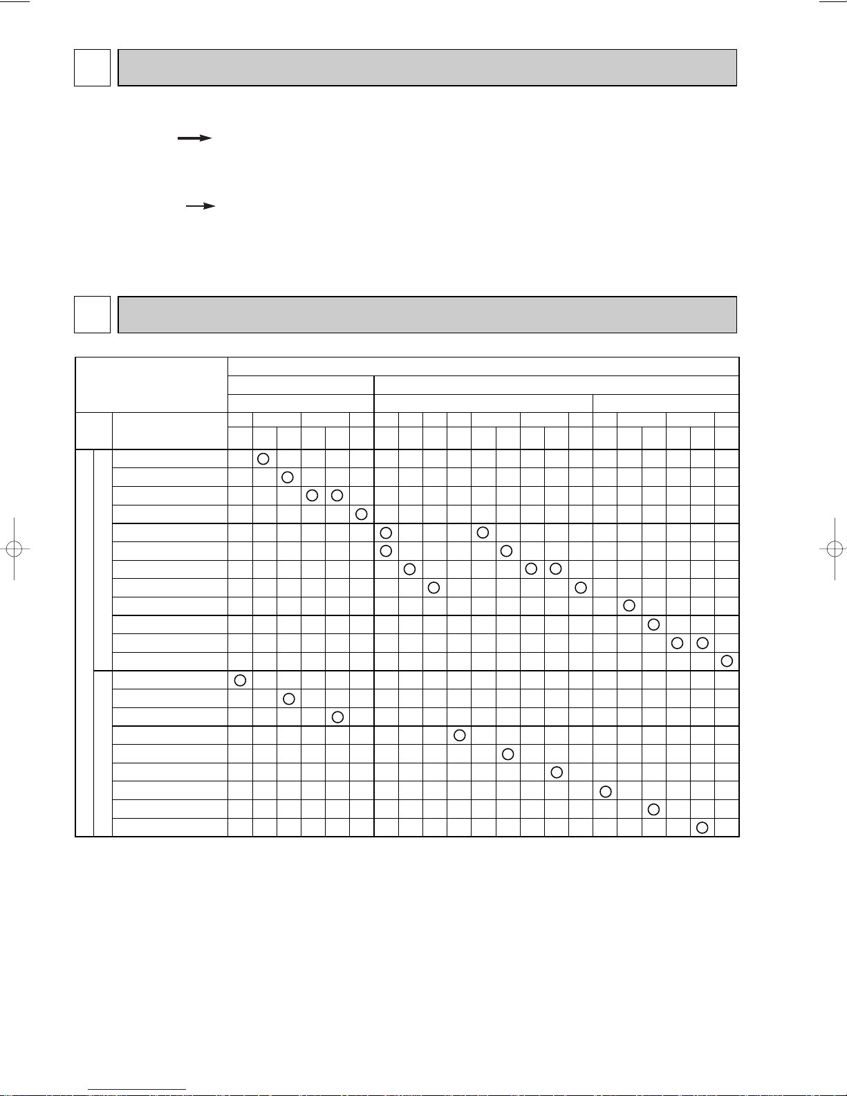
Indoor unit
SUH- • .TH
Heat pump type
Outdoor unit
Cooling only type
SU- • .TH SU- • .TH-T
VR1
VR2
TECHNICAL CHANGES
(REVISED EDITION-A)
SUH-2VR1.TH SUH-2VR2.TH
● OUTDOOR HEAT EXCHANGER has changed.
● RESTRICTOR VALVE has changed.
● CAPILLARY TUBE has changed.
({4.0X{2.4XL660) ({3.0X{2.0XL250)
2
COMBINATION OF INDOOR OUTDOOR UNITS
2
Page 3
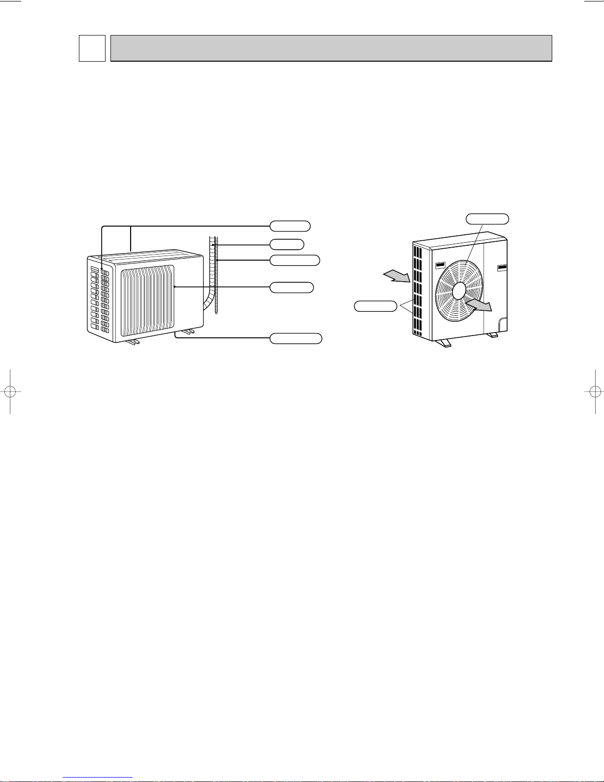
3
Air intake
Air outlet
Drain outlet
Piping
Drain hose
Air inlet
Air outlet
PART NAMES AND FUNCTIONS
SUH-1VR.TH SUH-1.6VR.TH SUH-2VR.TH SUH-2.5VR.TH
SUH-1.6VR2.TH SUH-2VR1.TH
SUH-2VR2.TH
SU-1.6NR.TH SU-2NR.TH SU-2.5NR.TH
SU-1VR.TH SU-1.6VR.TH SU-2VR.TH SU-2.5VR.TH
SU-1.6VR2.TH SU-2VR1.TH
SU-1VR.TH-T SU-1.6VR.TH-T SU-2VR.TH-T SU-2.5VR.TH-T
SU-1.6VR2.TH-T SU-2VR1.TH-T
3
Page 4
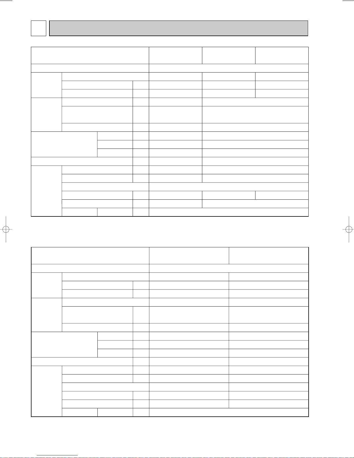
4
SUH-2VR.TH
SUH-2VR1.TH
SUH-2VR2.TH
Single phase, 220-240V, 50Hz
33.18
NH-38VMDT
1700
C-R: 1.07 C-S: 2.26
RA6V50-OF
WHT-BLK : 116
BLK-RED : 111
28(990)
850
605
290
59
52
810-845
1.8
MS-32(N-1) O 1.2
SUH-2.5VR.TH
NH-47VMDT
2200
C-R: 0.96 C-S: 2.70
RA6V85-AA
45(1590)
870
850
295
72
53
720-750
2
2.4
MS-32(N-1) O 1.2
WHT-BLK : 62.7
BLK-YLW : 30.2
YLW-RED : 62.9
1
Power supply
Service Ref.
W
"
"
m3/min(CFM)
mm
mm
mm
kg
dB
rpm
kg
R
k"
Compressor
Outdoor
fan motor
Dimensions
Width
Height
Depth
RT61(at 0:)
Weight
Special
remarks
Model
Output
Winding resistance (at 20:)
Model
Winding resistance (at 20:)
Airflow
Sound level (Hi)
Fan speed (Hi)
Fan speed regulator
Refrigerant filling capacity (R-22)
Refrigerant oil
Thermistor
SUH-1VR.TH
Single phase, 220-240V, 50Hz
SUH-1.6VR.TH
RH-174VGHT
800
C-R: 3.30 C-S: 5.80
PN6V23-UA
WHT-BLK : 353
BLK-RED : 321
28(990)
780
540
255
33
47
710-760
0.8
MS-56 O 0.30
RH-247VHAT
1200
C-R: 2.13 C-S: 3.91
1
1.65
33.18
SUH-1.6VR2.TH
RH-277VHAT
1300
C-R: 1.80 C-S: 3.00
1.4
RA6V40-EE
WHT-BLK : 130
BLK-RED : 135
36(1270)
850
605
290
43
50
780-820
MS-56 O 0.52
SPECIFICATIONS
4
Page 5
Compressor
Outdoor
fan motor
Dimensions
Weight
Special
remarks
Service Ref.
Power supply
Model
Output
Winding resistance (at 20:)
Model
Winding resistance (at 20:)
Airflow
Width
Height
Depth
Sound level (Hi)
Fan speed (Hi)
Fan speed regulator
Refrigerant filling capacity (R-22)
Refrigerant oil
Thermistor
RT61(at 0:)
W
"
C-R: 3.30 C-S: 5.80
"
m3/min(CFM)
mm
mm
mm
kg
dB
rpm
kg
R
k"
SU-1VR.TH
SU-1VR.TH-T
RH-174VGHT
800
RA6V23-HC
WHT-BLK : 353
BLK-RED : 321
28(990)
780
540
255
32
45
710-760
0.8
MS-56 O 0.30
SU-1.6VR.TH
SU-1.6VR.TH-T
Single phase, 220-240V, 50Hz
RH-247VHAT
1200
C-R: 2.13 C-S: 3.91
RA6V40-EE
WHT-BLK : 130
BLK-RED : 135
37(1310)
850
605
290
38
50
780-820
1
0.9
MS-56 O 0.52
33.18
SU-1.6VR2.TH
SU-1.6VR2.TH-T
RH-277VHAT
1300
C-R: 1.80 C-S: 3.00
Compressor
Outdoor
fan motor
Dimensions
Weight
Special
remarks
Service Ref.
Power supply
Model
Output
Winding resistance (at 20:)
Model
Winding resistance (at 20:)
Airflow
Width
Height
Depth
Sound level (Hi)
Fan speed (Hi)
Fan speed regulator
Refrigerant filling capacity (R-22)
Refrigerant oil
Thermistor
RT61(at 0:)
W
"
"
m3/min(CFM)
mm
mm
mm
kg
dB
rpm
kg
R
k"
SU-2VR.TH SU-2VR1.TH
SU-2VR.TH-T SU-2VR
NH38VMDT
1700
C-R: 1.07 C-S: 2.26
RA6V50-OF
WHT-BLK : 116
BLK-RED : 111
28(990)
850
605
290
55
52
810-845
1
1.6
MS-32(N-1) O 1.2
1.TH-T
Single phase, 220-240V, 50Hz
SU-2.5VR.TH
SU-2.5VR.TH-T
NH47VMDT
2200
C-R: 0.96 C-S: 2.70
RA6V60-AB
WHT-BLK : 81
BLK-YLW : 92.2
YLW-RED : 102
39(1380)
850
605
290
61
53
860-890
2
2.15
MS-32(N-1) O 1.2
33.18
5
Page 6
SU-1.6NR.TH SU-2NR.TH
Single phase, 220V, 60Hz
RH-207NHDT
1000
C-R: 1.68 C-S: 2.78
RA6V40-EE
WHT-BLK : 130
BLK-RED : 135
38(1340)
38
51
820
0.9
MS-56 O 0.52
NH-33NCDT
1500
C-R: 0.92 C-S: 1.93
RA6V50-OF
WHT-BLK : 116
BLK-RED : 111
39(1380)
850
605
290
55
52
860
1.65
MS-32(N-1) O 0.85
33.18
SU-2.5NR.TH
NH-38NBDT
1700
C-R: 0.83 C-S: 1.83
RA6V60-AB
41(1450)
61
54
930
2
2.15
MS-32(N-1) O 1.2
WHT-BLK : 81
BLK-YLW : 92
YLW-RED : 102
1
Power supply
Service Ref.
W
"
"
m3/min(CFM)
mm
mm
mm
kg
dB
rpm
kg
R
k"
Compressor
Outdoor
fan motor
Dimensions
Width
Height
Depth
RT61(at 0:)
Weight
Special
remarks
Model
Output
Winding resistance (at 20:)
Model
Winding resistance (at 20:)
Airflow
Sound level (Hi)
Fan speed (Hi)
Fan speed regulator
Refrigerant filling capacity (R-22)
Refrigerant oil
Thermistor
6
Page 7
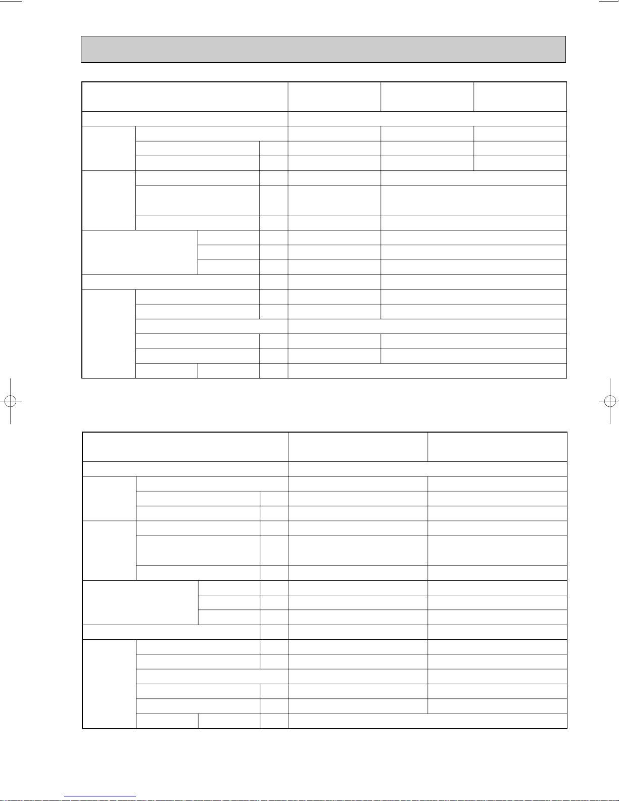
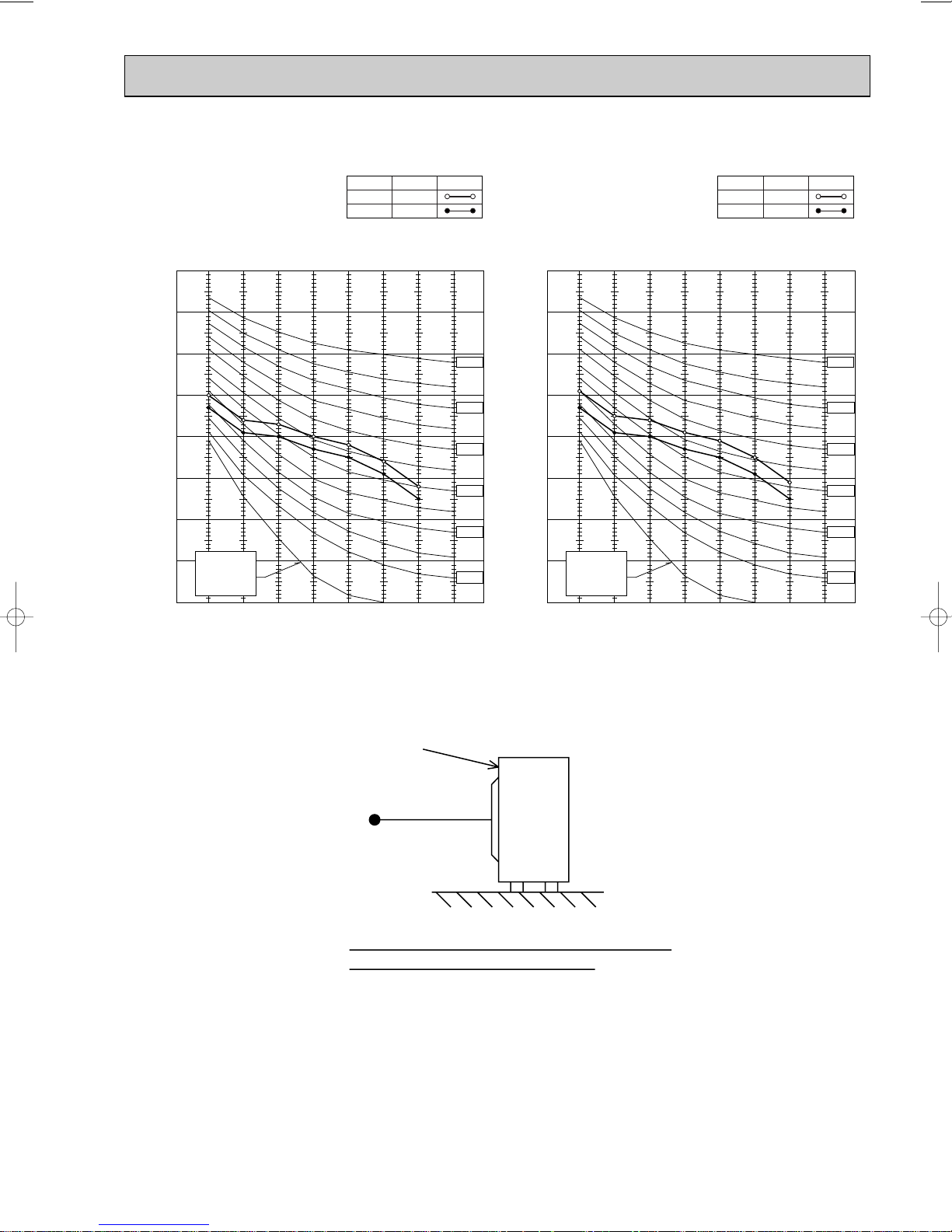
DATA5
90
80
70
60
50
40
30
20
10
63 125 250 500 1000 2000 4000 8000
OCTAVE BAND SOUND PRESSURE LEVEL, dB re 0.0002 MICRO BAR
BAND CENTER FREQUENCIES, Hz
NC-60
NC-50
NC-40
NC-30
NC-70
NC-20
APPROXIMATE
THRESHOLD OF
HEARING FOR
CONTINUOUS
NOISE
SUH-1VR.TH
47
SPL(dB) LINE
<50Hz>
90
80
70
60
50
40
30
20
10
63 125 250 500 1000 2000 4000 8000
OCTAVE BAND SOUND PRESSURE LEVEL, dB re 0.0002 MICRO BAR
BAND CENTER FREQUENCIES, Hz
NC-60
NC-50
NC-40
NC-30
NC-70
NC-20
APPROXIMATE
THRESHOLD OF
HEARING FOR
CONTINUOUS
NOISE
SUH-1.6VR.TH
SUH-1.6VR2.TH
50
SPL(dB) LINE
<50Hz>
90
80
70
60
50
40
30
20
10
63 125 250 500 1000 2000 4000 8000
OCTAVE BAND SOUND PRESSURE LEVEL, dB re 0.0002 MICRO BAR
BAND CENTER FREQUENCIES, Hz
NC-60
NC-50
NC-40
NC-30
NC-70
NC-20
APPROXIMATE
THRESHOLD OF
HEARING FOR
CONTINUOUS
NOISE
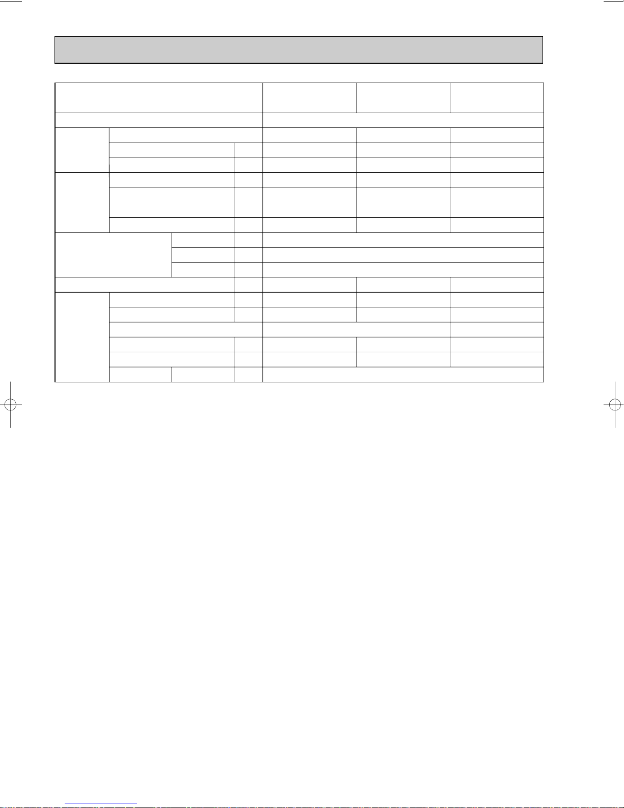
SUH-2VR.TH
SUH-2VR
1.TH
SUH-2VR
2.TH
52
SPL(dB) LINE
<50Hz>
90
80
70
60
50
40
30
20
10
63 125 250 500 1000 2000 4000 8000
OCTAVE BAND SOUND PRESSURE LEVEL, dB re 0.0002 MICRO BAR
BAND CENTER FREQUENCIES, Hz
NC-60
NC-50
NC-40
NC-30
NC-70
NC-20
APPROXIMATE
THRESHOLD OF
HEARING FOR
CONTINUOUS
NOISE
SUH-2.5VR.TH
Hi
Lo
NOTCH
53
51
SPL(dB) LINE
<50Hz>
NOISE CRITERION CURVES
7
Page 8
90
80
70
60
50
40
30
20
10
63 125 250 500 1000 2000 4000 8000
OCTAVE BAND SOUND PRESSURE LEVEL, dB re 0.0002 MICRO BAR
BAND CENTER FREQUENCIES, Hz
NC-60
NC-50
NC-40
NC-30
NC-70
NC-20
APPROXIMATE
THRESHOLD OF
HEARING FOR
CONTINUOUS
NOISE
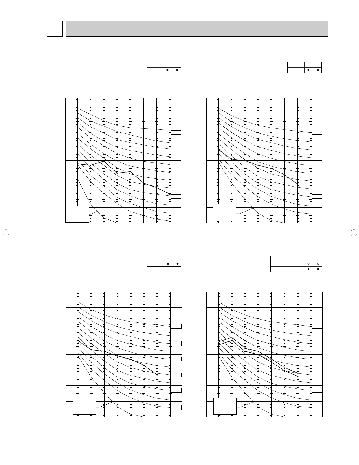
SU-1VR.TH
SU-1VR.TH-T
45
SPL(dB) LINE
<50Hz>
90
80
70
60
50
40
30
20
10
63 125 250 500 1000 2000 4000 8000
OCTAVE BAND SOUND PRESSURE LEVEL, dB re 0.0002 MICRO BAR
BAND CENTER FREQUENCIES, Hz
NC-60
NC-50
NC-40
NC-30
NC-70
NC-20
APPROXIMATE
THRESHOLD OF
HEARING FOR
CONTINUOUS
NOISE
SU-1.6NR.TH
51
SPL(dB) LINE
<60Hz>
90
80
70
60
50
40
30
20
10
63 125 250 500 1000 2000 4000 8000
OCTAVE BAND SOUND PRESSURE LEVEL, dB re 0.0002 MICRO BAR
BAND CENTER FREQUENCIES, Hz
NC-60
NC-50
NC-40
NC-30
NC-70
NC-20
APPROXIMATE
THRESHOLD OF
HEARING FOR
CONTINUOUS
NOISE
SU-1.6VR.TH
SU-1.6VR2.TH
SU-1.6VR.TH-T
SU-1.6VR2.TH-T
50
SPL(dB) LINE
<50Hz>
90
80
70
60
50
40
30
20
10
63 125 250 500 1000 2000 4000 8000
OCTAVE BAND SOUND PRESSURE LEVEL, dB re 0.0002 MICRO BAR
BAND CENTER FREQUENCIES, Hz
NC-60
NC-50
NC-40
NC-30
NC-70
NC-20
APPROXIMATE
THRESHOLD OF
HEARING FOR
CONTINUOUS
NOISE
SU-2VR.TH
SU-2VR
1.TH
SU-2NR.TH
SU-2VR.TH-T
SU-2VR
1.TH-T
52
SPL(dB) LINE
<50/60Hz>
8
Page 9
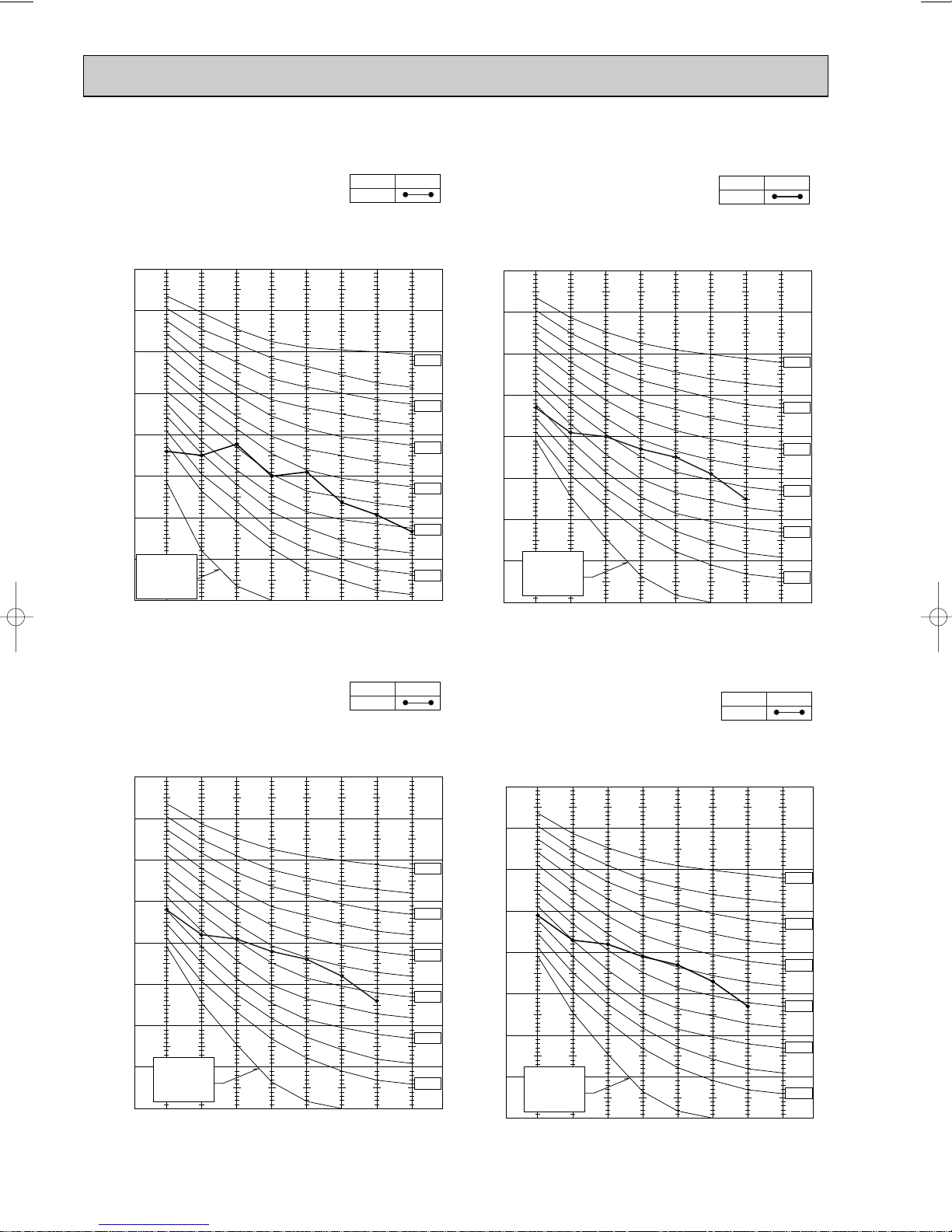
SU-2.5VR.TH
1m
UNIT
MICROPHONE
Ambient temperature 35°C (Cooling) / 7°C (Heating)
Test conditions are based on JIS Z8731
SU-2.5VR.TH-T
NOTCH
Hi
Lo
<50Hz>
SPL(dB) LINE
53
50
SU-2.5NR.TH
NOTCH
Hi
Lo
<60Hz>
SPL(dB) LINE
54
50
90
80
70
60
50
40
30
APPROXIMATE
20
THRESHOLD OF
HEARING FOR
CONTINUOUS
OCTAVE BAND SOUND PRESSURE LEVEL, dB re 0.0002 MICRO BAR
NOISE
10
63 125 250 500 1000 2000 4000 8000
BAND CENTER FREQUENCIES, Hz
NC-70
NC-60
NC-50
NC-40
NC-30
NC-20
90
80
70
60
50
40
30
APPROXIMATE
20
THRESHOLD OF
HEARING FOR
CONTINUOUS
NOISE
OCTAVE BAND SOUND PRESSURE LEVEL, dB re 0.0002 MICRO BAR
10
63 125 250 500 1000 2000 4000 8000
BAND CENTER FREQUENCIES, Hz
NC-70
NC-60
NC-50
NC-40
NC-30
NC-20
9
Page 10
6
320
25
43-
35-
155
90
104
74
260
10
780
500
122
40
540
320
285
255
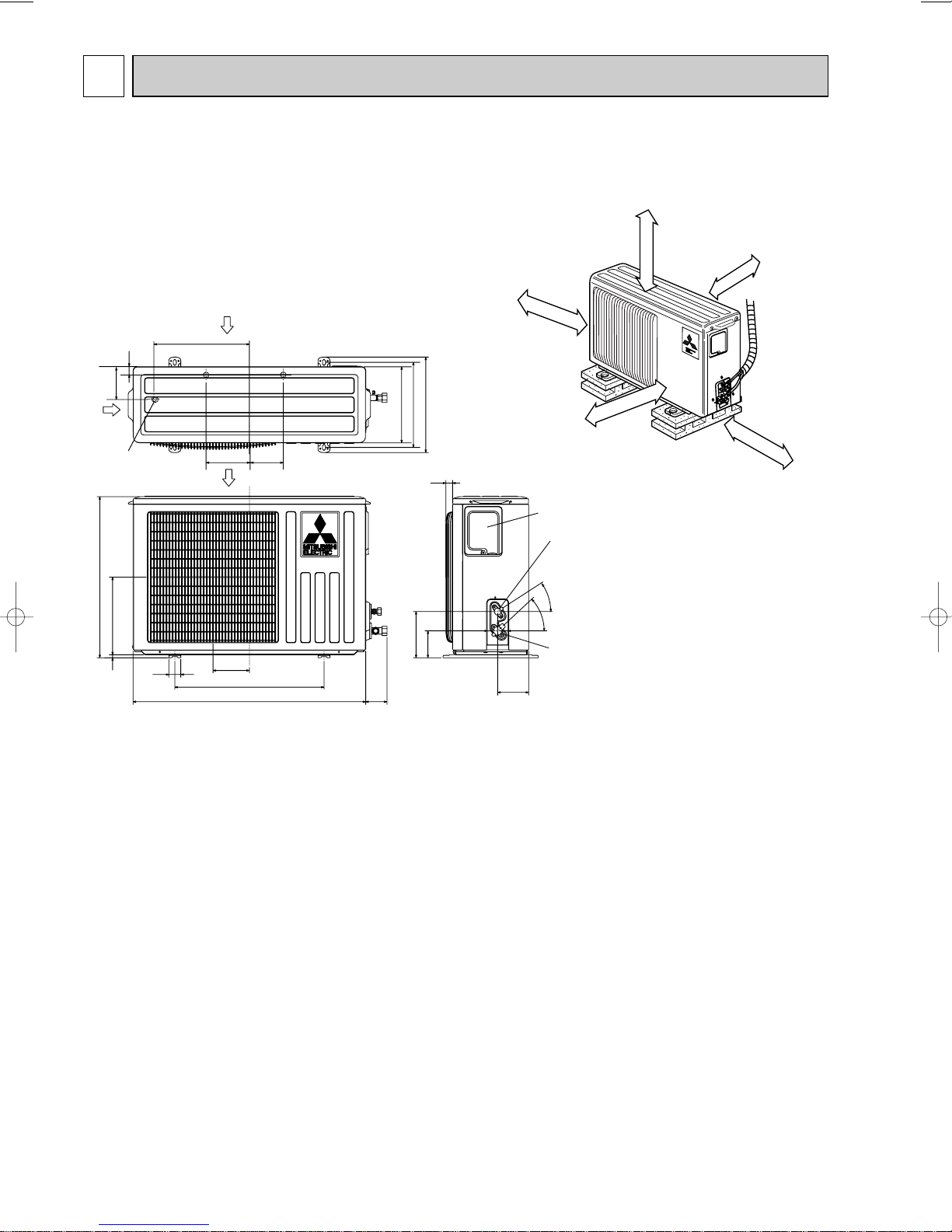
Service panel
Gas refrigerant
pipe joint
Refrigerant pipe
(flared) [9.52
Liquid refrigerant
pipe joint
Refrigerant pipe
(flared) [6.35
Air out
Air in
Air in
109
32
110
147
Drainage
3holes [33
If clearance
behind the outdoor
units only 40B or 50B
side A must be
fully open.
10cm or more
10cm or more
10cm or more
Outdoor
unit
35cm or more
REQUIRED SPACE
A
40cm or more
OUTLINES AND DIMENSIONS
SUH-1VR.TH
SU-1VR.TH
SU-1VR.TH-T
Unit: mm
10
Page 11
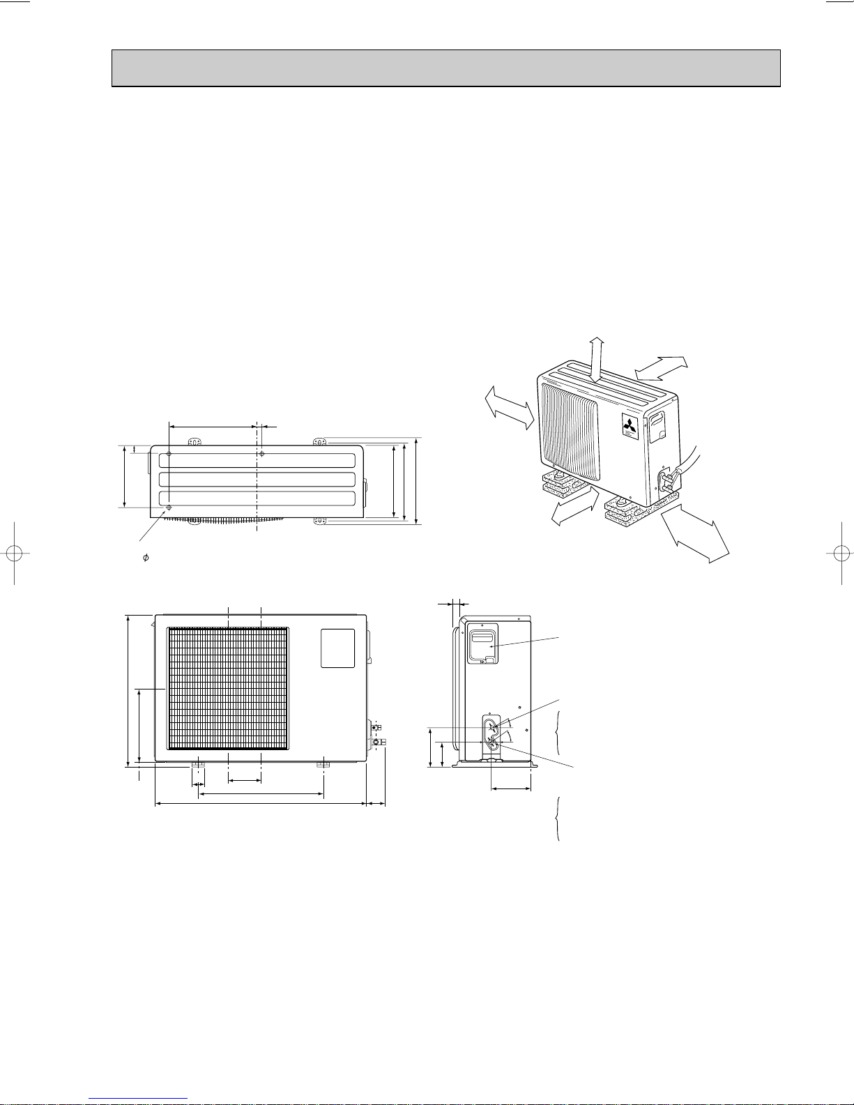
350
Drainage
3holes 16.2
35
248
20
290
310
345
10cm or more
10cm or more
10cm or more
50cm or more
35cm or more
If the right/left sides or
back side is vacant,the
front has only to be 50cm
unobstructed.
If the front or right/left sides
are vacant, the top has only
to be 10cm unobstructed.
605
29220
50
183
500
161
850
74
30
100
157
35
30
Service panel
Liquid refrigerant
pipe joint
Refrigerant pipe
(flare)
Gas refrigerant
pipe joint
Refrigerant pipe
(flare)
[12.7 (SUH-1.6VR(2).TH) (SU-1.6NR.TH)
(SU-1.6VR(2).TH,SU-1.6VR(2).TH-T)
[15.88 (SUH-2VR.TH) (SU-2/2.5NR.TH)
(SU-2/2.5VR.TH,SU-2/2.5VR.TH-T)
[6.35 (SUH-1.6/2VR(2).TH) (SU-1.6/2NR.TH)
(SU-1.6/2VR(2).TH,SU-1.6/2VR(2).TH-T)
[9.52 (SU-2.5NR.TH)
(SU-2.5VR.TH,SU-2.5VR.TH-T)
SUH-1.6VR.TH SUH-2VR.TH
SUH-1.6VR2.TH SUH-2VR1.TH
SUH-2VR2.TH
SU-1.6NR.TH SU-2NR.TH SU-2.5NR.TH
SU-1.6VR.TH SU-2VR.TH SU-2.5VR.TH
SU-1.6VR2.TH SU-2VR1.TH
SU-1.6VR.TH-T SU-2VR.TH-T SU-2.5VR.TH-T
SU-1.6VR2.TH-T SU-2VR1.TH-T
Unit: mm
11
Page 12
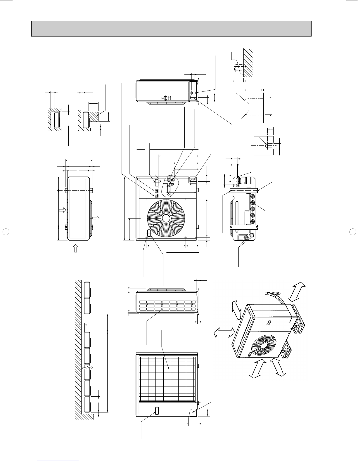
100 10
1000For 10 units or less
200
Outdoor Unit-Necessary surrounding clearance
(Concentrated installation)
The upper side must be open.
Outdoor Unit-Necessary surrounding clearance
200
10
10
10
Note:Allow adequate
upper clearance
150
500
500
Service space
Front opening
Handle
for moving
138
95
Rear piping hole
23
33
Rear fresh
air intake
Side air intake
724295
Outlet guide
installation hole
302
Air intake
Air intake
Air outlet
870
185 185
500
330
362
1715
39.5 27.5
Terminal block for indoor and outdoor unit connection
Terminal block for power line
Handle for moving
179 524
441
337
352
403
553
850
40 60524
Service panel
Refrigerant-pipe flared
connection [15.88 5/8F
Refrigerant-pipe flared
connection [9.52 3/8F
Knock out hole
for front piping
(refrigerant,drainage
and wiring)
Knock out hole
for right piping
(refrigerant,drainage
and wiring)
R20
R20
60
120
4553
25 max.
Knock out holes for
power line 2-[27
Standard bolt length
65
Front right piping holes-
detail figures
80
17
42
45
12
R6
104
33
Bottom
piping hole
2-U-shaped
notched
holes
Drain hole
Drain hole
2-12o23 Oval holes
(standard bolt M10)
Handle for moving
Unit : mm
SUH-2.5VR.TH
More than 100 mm
More than 200 mm if three
area obstacles to both sides.
More than 350 mm
12
Open as a rule
More than 500 mm if the
front and both sides are open.
More than 10 mm
Open as a rule
More than 500 mm if the
back both sides and top
are open.
Page 13
7
CN720
52C
X62
21S4
CN721
MF
SR61
CN611
MC
3
2
1
locking lever
1 Slide the sleeve.
2 Pull the wire while
pushing the locking lever.
sleeve
WHT
WHT
VLT
VLT
NO
COM
52C
w
TAB21
WHT
RED
RED
WHT
w
BLU
RED
BLK
CN730
C65
DEICER P.C. BOARD
RT61
F61
IC881
X62
CN711
BLK
NR61
TRANS
TAB20
RS
C
C1
TO
INDOOR UNIT
CONNECTING
3 w
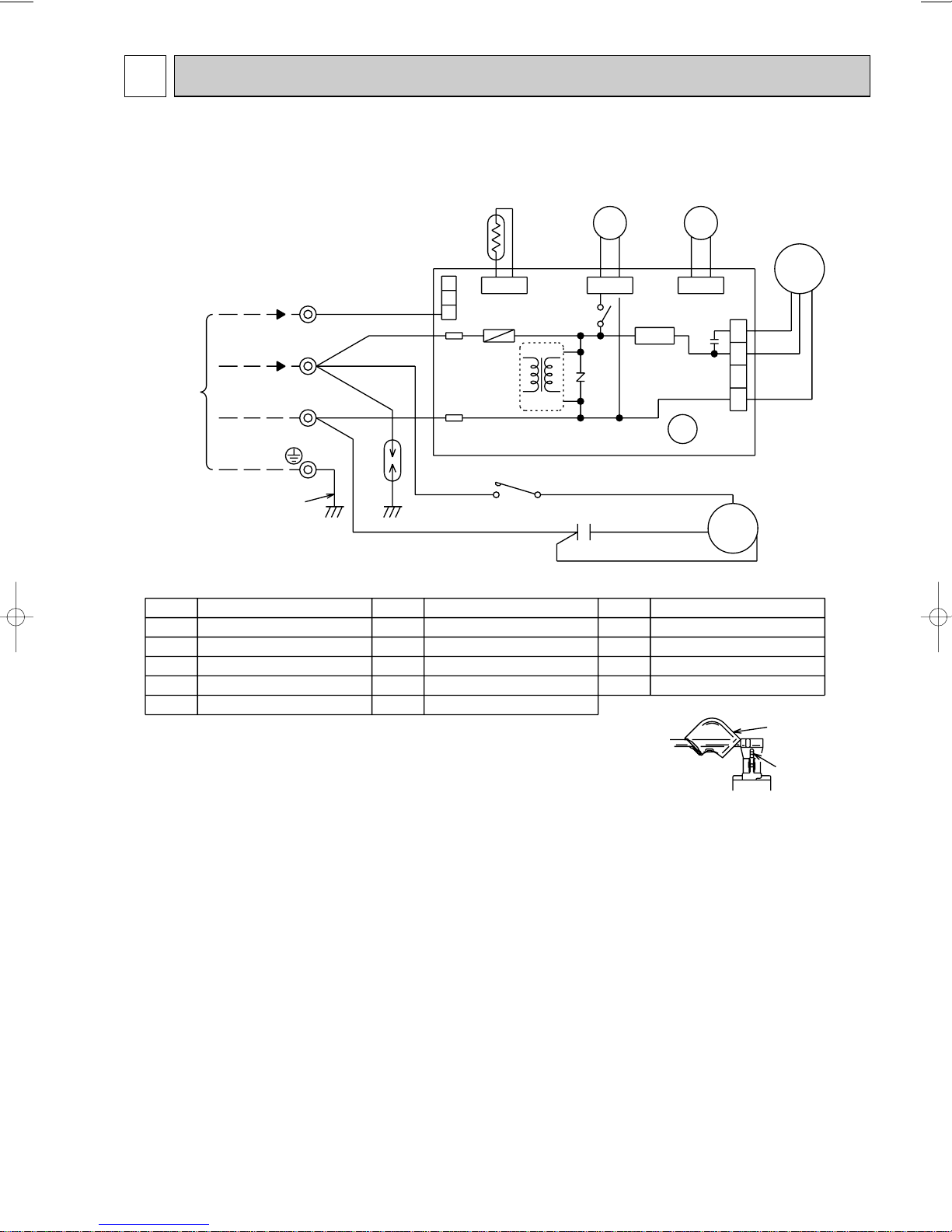
NAME
SYMBOL
NAME
SYMBOL
NAME
SYMBOL
C1
C65
DSAR
F61
IC881
COMPRESSOR CAPACITOR
FAN MOTOR CAPACITOR
SURGE ABSORBER
FASE (2A)
DC/DC CONVERTER
NOTE :1. Use copper conductors only (For field wiring).
2. “w” shows the terminals with a lock mechanism, so they cannot be
removed when you pull the lead wire.
Be sure to pull the lead wire by pushing the locking lever (projected part)
of the terminal with a finger.
MC
MF
NR61
RT61
SR61
COMPRESSOR (INNER THERMOSTAT)
FAN MOTOR (INNER THERMOSTAT)
VARISTOR
DEFROST THERMISTOR
SOLID STATE RELAY
TB
X62
21S4
52C
TERMINAL BLOCK
4-WAY VALVE RELAY
4-WAY VALVE SOLENOID COIL
COMPRESSOR CONTACTOR
w
TB
12VDC
220-240V~
2
WHT
DSAR
w
BLU
GRN/YLW
N
4
3
2
1
BLK
BLK
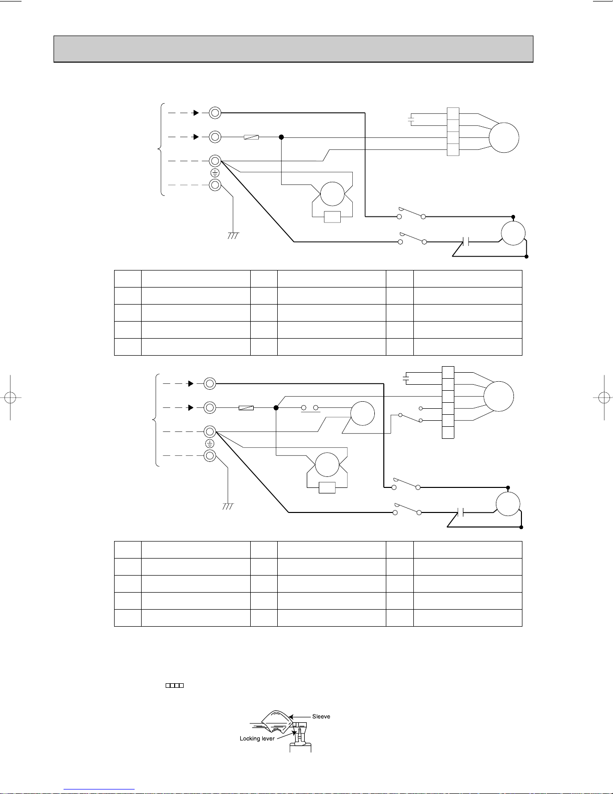
WIRING DIAGRAM
SUH-1VR.TH
13
Page 14

SUH-1.6VR.TH SUH-2VR.TH
220-240V
12VDC
RED
BLK
BLU
F
WHT
WHT
WHT
DSAR
TB
GRN/YLW
RED
W
W
WW
W
W
W
W
W
3
2
N
TO INDOOR
UNIT
CONNECTING
WHT
BLU
BLK
WHT
ORN
RED
MF
BLU
WHT
A1
A2
VLT YLW
CR
52C1
BLU
CZ
WHTWHT
T3/6L3/5
L1/1 T1/2
52C1
WHT
C1
RED
BLK
S
C
R
MC
4
TAB20
52C
3
YLW
CN730
2
1
3
C65
SR61
X62
NR61
TRANS
IC881
BLK
CN721
BLK
21S4
DEICER
P.C. BOARD
CN711
CN661
123
RT61
4
F61
2
1
3
4
TB
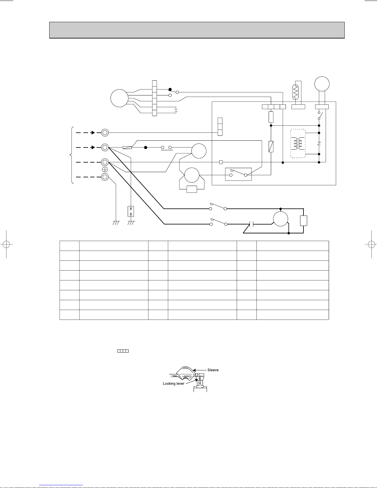
CZ SURGE ABSORBER 3
CR SURGE ABSORBER 2
IC881 DC/DC CONVERTER
F61 FUSE (2A)
CONTACTOR
4-WAY VALVE SOLENOID COIL
21S4
X62
MF
FAN MOTOR
<INNER THERMOSTAT>
MC
COMPRESSOR
<INNER THERMOSTAT>
SR61
RT61
NR61 V ARIST OR
F
C65
SYMBOL
NAME NAME
C1
DSAR
SYMBOL
COMPRESSOR CAPACITOR
SURGE ABSORBER 1FAN MOTOR CAPACITOR
FUSE (2A)
TERMINAL BLOCK
52C1
52C
COMPRESSOR CONTACTOR
4-WAY
VALVE RELAY
SOLID STATE RELAY
DEFROST THERMISTOR
NAME
SYMBOL
SUH-1.6VR2.TH SUH-2VR1.TH
SUH-2VR2.TH
NOTE :1. Use copper conductors only. (For field wiring)
2. Since the indoor and outdoor unit connecting wires have polarity, connect them according to the numbers
(N,2,3 and ;).
3. Symbols below indicate.
/:Terminal block, : Connector
4. ”w” shows the terminals with a lock mechanism,so they cannot be removed when you pull the lead wire.
Be sure to pull the wire by pushing the locking lever (projected part) of the terminal with a finger.
1Slide the sleeve.
2Pull the wire while pushing the locking lever.
14
Page 15
SUH-2.5VR.TH
RED
ORN
WHT
BLK
YLW
12VDC
TB
YLW
2
1
BLK
WHT
ORN
RED
3
4
5
6
MF
X1
BRN
SR61
X62
BLK
CN721
CN730
2
1
3
BLK
21S4
1
5
3
C2
CN711
CN661
123
RT61
4
A2
A1
ORN
WHT
YLWVLT
TB2
CR
WHT
4
52C1
F61
NR61
TRANS
IC881
220-240V~
DSAR
GRN/YLW
RED
W
W
W
W
WW
3
2
N
TO INDOOR
UNIT
CONNECTING
WHT
RED
7
RED
VLT
BLU
26F1
X1
WHT
TAB20
52C
3
YLW
DEICER
P.C. BOARD
BLU
WHTWHT
CZ
T3/6L3/5
BLU
L1/1 T1/2
52C1
WHT
C1
RED
BLK
S
C
R
MC
BLU
8
F
CZ SURGE ABSORBER 3
CR SURGE ABSORBER 2
IC881 DC/DC CONVERTERF61 FUSE (2A)
CONTACTOR
4-WAY VALVE SOLENOID COIL
21S4
X62
MF
FAN MOTOR
<INNER THERMOSTAT>
MC
COMPRESSOR
<INNER THERMOSTAT>
TB,TB2
SR61
RT61
NR61 V ARIST OR
F
C2
SYMBOL
NAME NAME
C1
DSAR
SYMBOL
COMPRESSOR CAPACITOR
SURGE ABSORBER 1
FAN MOTOR CAPACITOR
FUSE (2A)
TERMINAL BLOCK
52C1
THERMAL REED SWITCH
26F1
X1 FAN MOTOR RELAY
52C
COMPRESSOR CONTACTOR
4-WAY VALVE RELAY
SOLID STATE RELAY
DEFROST THERMISTOR
NAME
SYMBOL
NOTE :1. Use copper conductors only. (For field wiring)
2. Since the indoor and outdoor unit connecting wires have polarity, connect them according to the numbers
(N,2,3 and ;).
3. Symbols below indicate.
/:Terminal block, : Connector
4. ”w” shows the terminals with a lock mechanism,so they cannot be removed when you pull the lead wire.
Be sure to pull the wire by pushing the locking lever (projected part) of the terminal with a finger.
1Slide the sleeve.
2Pull the wire while pushing the locking lever.
15
Page 16
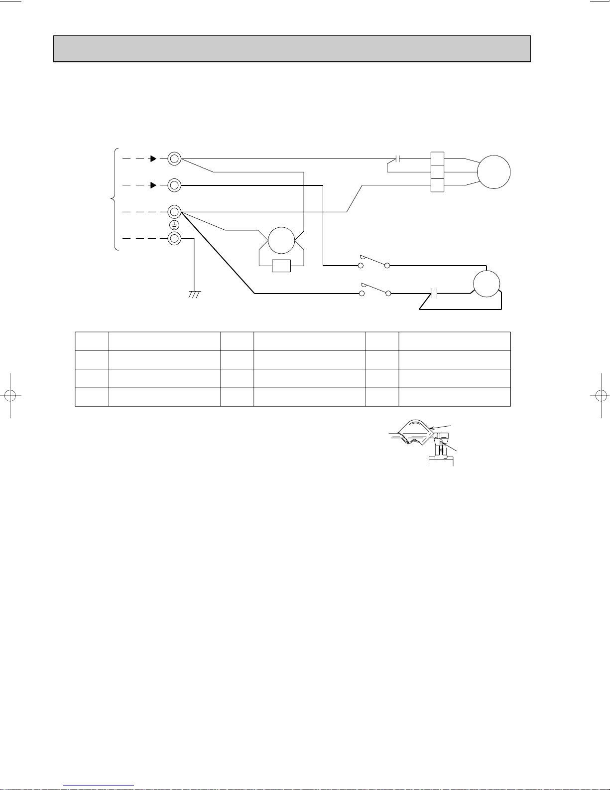
SU-1VR.TH
RED
WHT
RED
BLU
locking lever
sleeve
COMPRESSOR CONTACTOR
52C
VLT
YLW
BLU
WHT
RED
52C
52C
2
1
3
C2
WHT
BLK
RED
WHT
MF
MC
CR
A2
A1
BLU
L1/1
L3/5
R
C
S
BLK
RED
C1
T1/2
T3/6
BLU
GRN/YLW
3
2
N
TB
TO
INDOOR UNIT
CONNECTING
220-240V~
220-240V~
w
w
w
1 Slide the sleeve.
2 Pull the wire while
pushing the locking lever.
NAME
SYMBOL
NAME
SYMBOL
NAME
SYMBOL
CR
C1
C2
SURGE ABSORBER
COMPRESSOR CAPACITOR
FAN MOTOR CAPACITOR
NOTE :1. Use copper conductors only (For field wiring).
2. “w” shows the terminals with a lock mechanism, so they cannot be
removed when you pull the lead wire.
Be sure to pull the lead wire by pushing the locking lever (projected part)
of the terminal with a finger.
MC
MF
TB
COMPRESSOR (INNER THERMOSTAT)
FAN MOTOR (INNER THERMOSTAT)
TERMINAL BLOCK
SU-1VR.TH-T
16
Page 17
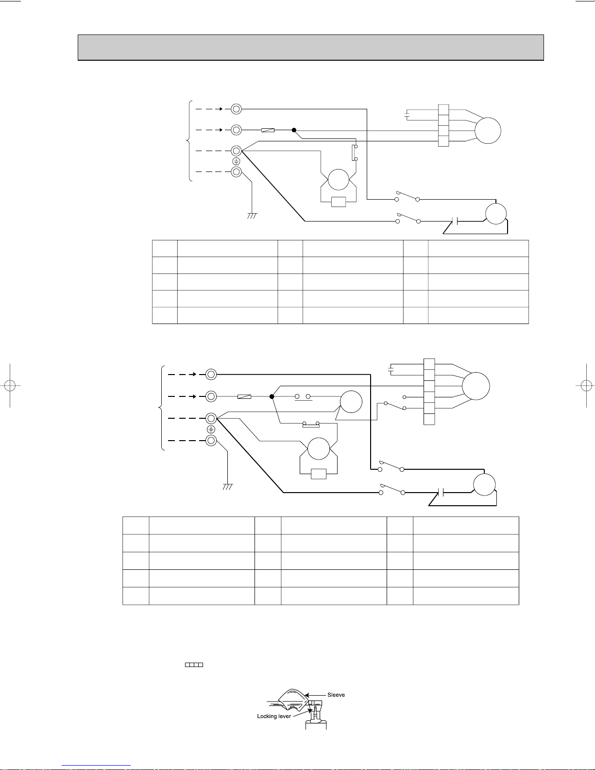
SU-1.6NR.TH
BLK
BLK
YLW
VLT
26C
BLU
WHT
RED
RED
BLU
WHT
ORN
RED
52C
52C
4
3
2
1
C2
WHT
BLK
ORN
RED
WHT
MF
MC
CR
A2
A1
BLU
F
TB2
L1/1
L3/5
R
C
S
BLK
RED
C1
T1/2
T3/6
BLU
GRN/YLW
2
3
TO INDOOR
UNIT
CONNECTING
W
W
W
TB
220V, 60Hz
220V, 60Hz
THERMAL SWITCH26C
TB2 TERMINAL BLOCKF FUSE(2A)
CR SURGE ABSORBER
TERMINAL BLOCK
COMPRESSOR CONTACTOR52C
TB
FAN MOTOR
(INNER THERMOSTAT)
(INNER THERMOSTAT)
COMPRESSOR
MC
FAN MOTOR CAPACITOR
COMPRESSOR CAPACITOR
C2
C1
NAME
SYMBOL
NAME
SYMBOL
NAME
SYMBOL
MF
N
YLW
VLT
BLK
CR
A2
A1
26C
BLK
BLU
ORN
BLU
X1
26F1
F
RED
8
7
BLU
RED
WHT
52C
TB2
RED
C2
GRN/YLW
2
3
RED
N
W
W
W
TB
220V, 60Hz
220V, 60Hz
L1/1
L3/5
MC
R
C
S
BLK
RED
C1
WHT
52C
T1/2
T3/6
BLU
TO INDOOR
UNIT
CONNECTING
1
3
5
X1
6
5
4
3
2
1
YLW
MF
YLW
BLK BLK
WHT
RED
ORN
WHT
ORN
RED
THERMAL SWITCH26CTB2 TERMINAL BLOCKF FUSE(2A)
CR SURGE ABSORBER
THERMAL LEAD SWITCH26F1
FAN MOTOR RELAYX1
TERMINAL BLOCK COMPRESSOR CONTACTOR52CTB
FAN MOTOR
(INNER THERMOSTAT)
(INNER THERMOSTAT)
COMPRESSOR
MF
MC
FAN MOTOR CAPACITOR
COMPRESSOR CAPACITOR
C2
C1
NAME
SYMBOL
NAME
SYMBOL
NAME
SYMBOL
SU-2NR.TH
SU-2.5NR.TH
NOTE :1. Use copper conductors only. (For field wiring)
2. Since the indoor and outdoor unit connecting wires have polarity, connect them according to the numbers
(N,2,3 and ;).
3. Symbols below indicate.
/:Terminal block, : Connector
4. ”w” shows the terminals with a lock mechanism,so they cannot be removed when you pull the lead wire.
Be sure to pull the wire by pushing the locking lever (projected part) of the terminal with a finger.
17
1Slide the sleeve.
2Pull the wire while pushing the locking lever.
Page 18
SU-1.6VR.TH
VLT
YLW
BLU
WHT
WHT
RED
RED
BLU
WHT
ORN
RED
52C
52C
4
3
2
1
C2
WHT
BLK
ORN
RED
WHT
MF
MC
CR
A1
A2
BLU
F
TB2
L1/1
L3/5
R
C
S
BLK
RED
C1
T1/2
T3/6
BLU
GRN/YLW
2
3
TO INDOOR
UNIT
CONNECTING
N
TB
220-240V,50Hz
220-240V,50Hz
W
W
W
W
W
W
YLW
VLT
BLU
ORN
1
3
5
X1
BLU
X1
26F1
F
RED
8
7
BLU
RED
WHT
52C
CR
TB2
WHT
RED
A1
A2
6
5
4
3
2
1
YLW
C2
MF
YLW
BLK BLK
WHT
RED
ORN
WHT
ORN
RED
L1/1
L3/5
MC
R
C
S
BLK
RED
C1
WHT
52C
T1/2
T3/6
BLU
GRN/YLW
2
3
RED
TO INDOOR
UNIT
CONNECTING
N
TB
220-240V,50Hz
220-240V,50Hz
W
W
W
TB2 TERMINAL BLOCKF FUSE(2A)
CR SURGE ABSORBER
TERMINAL BLOCK
COMPRESSOR CONTACTOR52C
TB
FAN MOTOR
(INNER THERMOSTAT)
(INNER THERMOSTAT)
COMPRESSOR
MF
MC
FAN MOTOR CAPACITOR
COMPRESSOR CAPACITOR
C2
C1
NAME
SYMBOL
NAME
SYMBOL
NAME
SYMBOL
TB2 TERMINAL BLOCKF FUSE(2A)
CR SURGE ABSORBER
THERMAL LEAD SWITCH26F1
FAN MOTOR RELAYX1
TERMINAL BLOCK COMPRESSOR CONTACTOR52CTB
FAN MOTOR
(INNER THERMOSTAT)
(INNER THERMOSTAT)
COMPRESSOR
MF
MC
FAN MOTOR CAPACITOR
COMPRESSOR CAPACITOR
C2
C1
NAME
SYMBOL
NAME
SYMBOL
NAME
SYMBOL
SU-1.6VR2.TH
SU-2VR.TH
SU-2VR1.TH
SU-1.6VR.TH-T
SU-1.6VR2.TH-T
SU-2VR.TH-T
SU-2VR1.TH-T
SU-2.5VR.TH
SU-2.5VR.TH-T
NOTE :1. Use copper conductors only. (For field wiring)
2. Since the indoor and outdoor unit connecting wires have polarity, connect them according to the numbers
(N,2,3 and ;).
3. Symbols below indicate.
/:Terminal block, : Connector
4. ”w” shows the terminals with a lock mechanism,so they cannot be removed when you pull the lead wire.
Be sure to pull the wire by pushing the locking lever (projected part) of the terminal with a finger.
18
1Slide the sleeve.
2Pull the wire while pushing the locking lever.
Page 19

8
Outdoor
heat
exchanger
Flared connection
Defrost
thermistor
RT61
Flared connection
Stop valve
Stop valve
(with service port)
(#100)
Strainer
Capillary tube
({3.0x{1.8xL330)w1
({3.0x{1.6xL420)w2
w1 SUH-1.6VR.TH
w2 SUH-1.6VR2.TH
Capillary
tube
({3.0x{1.6xL550)w1
({3.0x{1.8xL550)w2
Restrictor valve
Refrigerant flow in cooling
Compressor
Accumulator
Strainer 1
(#100)
valve
Muffler
Refrigerant flow in heating
Refrigerant pipe [12.7
(Option)
(with heat insulator)
Refrigerant pipe
(Option) [6.35
(with heat insulator)
Discharge
Pressure
Regulator
Reversing
Outdoor
heat
exchanger
Flared connection
Flared connection
Stop valve
Stop valve
(with service port)
(#100)
Strainer 2
Capillary tube
({3.0x{1.4xL580)
Capillary tube
({3.0x{1.6xL400)
Restrictor valve
Refrigerant flow in cooling
Compressor
Accumulator
Strainer 1
(#100)
valve
Muffler
Refrigerant flow in heating
Refrigerant pipe [9.52
(Option)
(with heat insulator)
Refrigerant pipe
(Option) [6.35
(with heat insulator)
Discharge
Pressure
Regulator
Reversing
Defrost
thermistor
RT61
Capillary
tube
({3.0X{1.4XL800)X2
REFRIGERANT SYSTEM DIAGRAM
SUH-1VR.TH
SUH-1.6VR.TH
SUH-1.6VR2.TH
19
Page 20

Outdoor
heat
exchanger
Flared connection
Distributor
Defrost
thermistor
RT61
Flared connection
Ball valve
(with service port)
Ball valve
(#100)
Strainer 3
Strainer 2
(#100)
Capillary tube
({4.0x{2.0xL410)
Refrigerant flow in cooling
Compressor
Charge
plug
Accumulator
Muffler
Reversing
valve
Refrigerant flow in heating
Refrigerant pipe [15.88
(Option)
(with heat insulator)
Refrigerant pipe
(Option) [9.52
(with heat insulator)
Discharge
Pressure
Regulator
Outdoor
heat
exchanger
Flared connection
Defrost
thermistor
RT61
Flared connection
Stop valve
Stop valve
(with service port)
(#100)
Strainer
Capillary tube
({4.0X{2.4XL660)···2VR
(1).TH
({3.0X{2.0XL250)···2VR2.TH
Capillary
tube
({3.0X{1.6XL860)X2
Restrictor valve
Refrigerant flow in cooling
Compressor
Accumulator
Strainer 1
(#100)
valve
Muffler
Refrigerant flow in heating
Refrigerant pipe [15.88
(Option)
(with heat insulator)
Refrigerant pipe
(Option) [6.35
(with heat insulator)
Discharge
Pressure
Regulator
Reversing
SUH-2VR.TH
SUH-2VR1.TH
SUH-2VR2.TH
SUH-2.5VR.TH
20
Page 21

SU-1.6NR.TH
Outdoor
heat
exchanger
Flared connection
Flared connection
Stop valve
Stop valve
(with service port)
(#100)
Strainer
Capillary tube
(
[3.0x[2.0xL100
)
Capillary tube
(
[3.0x[2.0xL700
)
Refrigerant flow
Compressor
Refrigerant pipe [15.88
(Option)
(with heat insulator)
Refrigerant pipe
(Option) [6.35
(with heat insulator)
Accumulator
Dis pressure
regulator
Outdoor
heat
exchanger
Flared connection
Flared connection
Stop valve
Stop valve
(with service port)
(#100)
Strainer
Capillary tube
(
[3.0x[1.8xL100
)
Capillary tube
(
[3.0x[1.8xL550
)
Refrigerant flow
Compressor
Refrigerant pipe [12.7
(Option)
(with heat insulator)
Refrigerant pipe
(Option) [6.35
(with heat insulator)
Dis pressure
regulator
SU-2NR.TH
21
Page 22

Outdoor
heat
exchanger
Flared connection
Flared connection
Stop valve
Stop valve
(with service port)
(#100)
Strainer
Capillary tube
(
[3.0x[1.4xL600
)
Refrigerant flow
Compressor
Refrigerant pipe [9.52
(Option)
(with heat insulator)
Refrigerant pipe
(Option) [6.35
(with heat insulator)
Dis pressure
regulator
Outdoor
heat
exchanger
Flared connection
Flared connection
Stop valve
Stop valve
(with service port)
(#100)
Strainer
Capillary tube
(
[3.0x[2.0xL100
)
Capillary tube
(
[3.0x[2.0xL600
)
Refrigerant flow
Accumulator
Compressor
Refrigerant pipe [15.88
(Option)
(with heat insulator)
Refrigerant pipe
(Option) [9.52
(with heat insulator)
SU-2.5NR.TH
SU-1VR.TH
SU-1VR.TH -T
22
Page 23

SU-1.6VR.TH
SU-1.6VR2.TH
SU-1.6VR.TH-T
SU-1.6VR2.TH-T
Refrigerant pipe [12.7
(Option)
(with heat insulator)
Flared connection
Flared connection
Stop valve
(with service port)
Compressor
(#100)
Strainer
Outdoor
heat
exchanger
SU-2VR.TH
SU-2VR
1.TH
SU-2VR.TH-T
SU-2VR1.TH-T
Refrigerant pipe
(Option) [6.35
(with heat insulator)
Refrigerant pipe [15.88
(Option)
(with heat insulator)
Flared connection
Stop valve
Stop valve
(with service port)
Refrigerant flow
Accumulator
Capillary tube
(
[3.0x[1.8xL800
(
[3.0x[1.8xL500
Compressor
)···SU-1.6VR.TH(-T)
)···SU-1.6VR2.TH(-T)
Outdoor
heat
exchanger
Flared connection
Refrigerant pipe
(Option) [6.35
(with heat insulator)
Stop valve
Refrigerant flow
23
Capillary tube
[3.0x[2.0xL570
(
)
(#100)
Strainer
Page 24

Dis pressure
regulator
Outdoor
heat
exchanger
Flared connection
Flared connection
Stop valve
Stop valve
(with service port)
(#100)
Strainer
Capillary tube
(
[3.0x[2.0xL100
)
Capillary tube
(
[3.0x[2.0xL700
)
Refrigerant flow
Accumulator
Compressor
Refrigerant pipe [15.88
(Option)
(with heat insulator)
Refrigerant pipe
(Option) [9.52
(with heat insulator)
SU-2.5VR.TH
SU-2.5VR.TH-T
24
Page 25

MAX. REFRIGERANT PIPING LENGTH & MAX. HEIGHT DIFFERENCE
Indoor unit
SEH-1.6AR.TH SEH-1.6AR
1.TH
SE-1.6AR.TH SE-1.6AR
1.TH
SE-1.6AR.TH-T
SE-1.6AR1.TH-T
SEH-2AR.TH
SE-2AR.TH
SE-2AR.TH-T
SEH-2.5AR.TH
SE-2.5AR.TH
SE-2.5AR.TH-T
SUH-1.6VR.TH SUH-1.6VR2.TH
SU-1.6NR.TH SU-1.6VR.TH SU-1.6VR2.TH
SU-1.6VR.TH-T SU-1.6VR2.TH-T
SUH-2VR.TH SUH-2VR
1.TH SUH-2VR2.TH
SU-2NR.TH SU-2VR.TH SU-2VR
1.TH
SU-2VR.TH-T SU-2VR
1
.TH-T
SUH-2.5VR.TH
SU-2.5NR.TH SU-2.5VR.TH
SU-2.5VR.TH-T
15(49)
{12.7(1/2)
{15.88(5/8)
{6.35(1/4)
{9.52(3/8)
Outdoor unit
Piping size O.D. : mm (in.)
Gas Liquid
Length : m(ft)
A
Service Ref.
Indoor unit
SEH-1.6AR.TH
SEH-1.6AR
1.TH
SEH-2AR.TH
SEH-2.5AR.TH
SE-1.6AR.TH SE-1.6AR1.TH
SE-1.6AR.TH-T SE-1.6AR1.TH-T
SE-2AR.TH
SE-2AR.TH
SE-2AR.TH-T
SE-2.5AR.TH
SE-2.5AR.TH-T
SUH-1.6VR.TH
SUH-1.6VR2.TH
SUH-2VR.TH SUH-2VR
1.TH SUH-2VR2.TH
SUH-2.5VR.TH
SU-1.6NR.TH SU-1.6VR.TH SU-1.6VR2.TH
SU-1.6VR.TH-T SU-1.6VR2.TH-T
SU-2NR.TH
SU-2VR.TH SU-2VR
1.TH
SU-2VR.TH-T SU-2VR
1.TH-T
SU-2.5VR.TH SU-2.5NR.TH
SU-2.5VR.TH-T
1650
1400
1800
2400
900
1650
1600
2150
0
0
50
65
15
100
130
30
150
195
45
200
260
60
250
325
75
300
390
90
350
455
105
400
520
120
Outdoor unit
Refrigerant piping length (one way)
7m 8m 9m 10m11m12m13m14m15m
Outdoor unit
precharged
(up to 7m)
Service Ref.
Calculation : (SEH-2.5AR)og=65g/mo(Refrigerant piping length minus 7m)
(SEH-1.6/2AR)og=50g/mo(Refrigerant piping length minus 7m)
(SE-)og=15g/mo(Refrigerant piping length minus 7m)
ADDITIONAL REFRIGERANT CHARGE (R-22 : g)
If pipe length exceeds 7m, additional refrigerant (Freon 22) charge is required
A : Refrigerant piping
Max.length
15m(49ft)
25
7m(23ft)
Max. Height difference *
(g)
Page 26

A: Refrigerant piping
Max.length
20m(66ft)
Max. Height difference *
8m(26ft)
MAX. REFRIGERANT PIPING LENGTH & MAX. HEIGHT DIFFERENCE
Indoor unit
SLH-1AR.TH
SL-1AR.TH
SL-1AR.TH-T
SLH-1.6AR.TH
SL-1.6AR.TH
SL-1.6AR.TH-T
SLH-2AR.TH
SL-2AR.TH
SL-2AR.TH-T
20(66)
{9.52(3/8)
{12.7(1/2)
{15.88(5/8)
{6.35(1/4)
Outdoor unit
Piping size O.D. : mm (in.)
Gas Liquid
Length : m(ft)
A
Models
wIt does not matter which unit is higher.
SUH-1VR.TH
SU-1VR.TH
SU-1VR.TH-T
SUH-1.6VR2.TH
SU-1.6VR2.TH
SU-1.6VR2.TH-T
SUH-2VR1.TH, SUH-2VR2.TH
SU-2VR1.TH
SU-2VR1.TH-T
Indoor unit
SLH-1AR.TH
SLH-1.6AR.TH
SLH-2AR.TH
SL-1AR.TH, SL-1AR.TH-T
SL-1.6AR.TH, SL-1.6AR.TH-T
SL-2AR.TH, SL-2AR.TH-T
SUH-1VR.TH
SUH-1.6VR2.TH
SUH-2VR1.TH SUH-2VR2.TH
SU-1VR.TH, SU-1VR.TH-T
SU-1.6VR2.TH, SU-1.6VR2.TH-T
SU-2VR
1.TH, SU-2VR1.TH-T
800
1,400
1,800
800
900
1,600
0
0
0
25
50
15
50
100
30
75
150
45
100
200
60
125
250
75
150
300
90
175
350
105
200
400
120
225
450
135
250
500
150
275
550
165
300
600
180
325
650
195
Outdoor unit
Refrigerant piping length (one way)
7m 8m 9m 10m 11m 12m 13m 14m 15m 16m 17m 18m 19m 20m
Outdoor unit
precharged
(up to 7m)
Models
Calculation : (SLH-1AR)og=25g/mo(Refrigerant piping length minus 7m)
(SLH-1.6/2AR)og=50g/mo(Refrigerant piping length minus 7m)
(SL-1/1.6/2AR)og=15g/mo(Refrigerant piping length minus 7m)
ADDITIONAL REFRIGERANT CHARGE (R-22 : g)
If pipe length exceeds 7m, additional refrigerant (Freon 22) charge is required
26
(g)
Page 27

Ball valve
(liquid side)
Service port
Valve knob Lo
Valve knob Hi
Charge hose
Vacuum
pump
Manifold
valve
Compound gauge Pressure gauge
-1.01✕10 Pa
(-760mmHg)
Stop valve
Stop valve
Stop valve
Close
Caps
Gauge manifold valve
Gas pipe
Connection
pipe
Open
Vacuum pump
Service port
Hexagonal
wrench
Liquid pipe
Hexagonal
wrench
EVACUATION PROCEDURES
Connect the refrigerant pipes (both the liquid and gas
pipes) between the indoor and the outdoor units.
Remove the service port cap of the stop/ball valve.
(The stop/ball valve will not work in its initial state fresh out of the factory (totally closed with cap on).)
Connect the gauge manifold valve and the vacuum pump to the service port of the stop/ball valve .
Run the vacuum pump. (Vacuumize for more than 15 minutes.)
Check the vacuum with the gauge manifold valve, then close the gauge manifold valve, and stop the
vacuum pump.
Leave as it is for one or two minutes. Make sure the pointer of the gauge manifold valve remains in the
same position. Confirm that the pressure gauge show-0.1MPa(-79cmHg)
<SUH-1, 1.6, 2>
<SUH-2.5>
<SU-1, 1.6, 2, 2.5>
Remove the gauge manifold valve quickly from the service port of the stop/ball valve.
After refrigerant pipes are connected and evacuated, fully open all stop/ball
valves on gas and liquid pipe sides.
Operating without fully opening lowers the performance and causes trouble.
Pipe length :
7m maximum
No gas charge is
needed.
Pipe length
exceeding 7m
Charge the prescribed
amount of gas.
Tighten the cap to the service port to obtain the initial status.
Retighten the cap.
Leak test
27
Page 28

9
9-1. Test point of P.C. board
•Deicer P.C. board
SUH-1VR.TH
SUH-1.6VR.TH
SUH-1.6VR2.TH
SUH-2VR.TH
SUH-2VR
SUH-2VR
SUH-2.5VR.TH
Outdoor fan motor
220-240V AC
TROUBLESHOOTING
1.TH
2.TH
Solenoid coil
}
220-240V AC
}
R601
5~10V DC
}
+
DEICER P.C. BOARD
INPUT
220-240V AC
}
Defrost thermistor(RT61)
}
}
12V DC
Fuse 2A/250V
Defrost interval
time short pin
+
J9
5V DC
}
J8
+
+
}
52C
12V DC
Defrost interval
Defrost termination
temperature change
Jumper wire JPC and JPE
28
Page 29

Check of deicer P.C. board and outdoor fan motor
SUH-1VR.TH
SUH-1.6VR.TH
SUH-1.6VR2.TH
SUH-2VR.TH
SUH-2VR
SUH-2VR
1.TH
2.TH
SUH-2.5VR.TH
Operation lamp blinks once in a fixed period.
Error was found in the signal transmitted or
received between the indoor and outdoor units.
Is the connecting wire between
the indoor and outdoor units
No
Connection is defective.
Yes
Remove the devices.
Turn off the power supply and turn it on again to operate the unit in
cooling or heating mode.
No
Normal
connected properly?
Yes
Are there any devices emitting
noise near the power supply or
the connecting wire between the
indoor and outdoor units?
No
Operation lamp blinks once in a
fixed period.
Yes
Deicer P.C. board is defective.
No
Connection is defective.
Yes
Defrost thermistor is defective.
Turn off the power supply and turn it on again to operate the unit in
heating mode.
No
Normal
Operation lamp blinks 6 times in a fixed period.
Check the defrost thermistor.
Is the connector CN661 on the
deicer P.C. board connected?
Yes
Measure the resistance of defrost thermistor.
Is the resistance 0 (short circuit) or
∞ (open circuit)?
No
Operation lamp blinks 6 times in a
fixed period.
Yes
Deicer P.C. board is defective.
To be continued on the next page.
29
Page 30

Yes
Indoor unit operates, while outdoor unit does not.
Compressor does not operate. Fan motor does not operate.
No
Is the voltage of contactor
terminals between A1 and A2
220-240V?
Connection is defective. Connection is defective.
Yes
No
Connection is defective.
No
Yes
No
Is the connecting wire between the
indoor and outdoor units connected
properly?
Yes
No
Does the contactor operate?
Yes
Is the connector connected properly?
Contactor is defective.
Yes
No
Is the output voltage of contactor
correct?
Connection is defective.
Check the compressor.
Yes
Contactor is defective.
No
Are the wires connected to the
compressor properly?
Is the connecting wire between the
indoor and outdoor units connected
properly?
Fan motor is defective.
Deicer P.C. board is defective.
Yes
No
Deicer P.C. board is defective.
Is the resistance of fan motor
normal?
From the preceding page.
30
Page 31

9-2. Trouble criterion of main parts
Defrost
thermistor
(Outdoor)
Compressor
Measure the resistance with a tester.
(Part temperature 10°C ~ 40°C)
Measure the resistance between the terminal with a tester.
(Coil wiring temperature 10°C ~ 40°C)
Measure the resistance between the terminals with a tester.
(Coil wiring temperature -10°C ~ 40°C)
1VR
1.6, 2NR
1.6, 2VR
1.6VR2, 2VR1, 2VR
2
SU-2.5NR
SU-2.5VR
SUH-2.5VR
Outdoor fan
motor
Check method and criterion
Part name
Normal
1VR
Normal
SUH-
WHT-BLK
BLK-RED
BLK-YLW
YLW-RED
311~381Ω
283~347Ω
—
—
1.6VR, 1.6VR2
115~141Ω
118~146Ω
—
—
2VR, 2VR1, 2VR2
102~126Ω
98~120Ω
—
—
2.5VR
55~68Ω
—
27~33Ω
55~68Ω
5kΩ~60kΩ
Abnormal
Abnormal
Opened or
short-circuited
1
VR
Normal
SU-
WHT-BLK
BLK-RED
BLK-YLW
311~381Ω
283~347Ω
—
1.6
NR, VR, VR2
115~141Ω
118~146Ω
—
2
NR, VR, VR
1
102~126Ω
98~120Ω
—
2.5
NR, VR
72~88Ω
90~110Ω
81~99Ω
Abnormal
Opened or
short-circuited
1VR
Normal
SUH-
C-R
C-S
2.9~3.6Ω
5.1~6.3Ω
1.9~2.3Ω
2.4~4.2Ω
1.6~2.0Ω
2.6~3.2Ω
0.9~1.2Ω
2.0~2.4Ω
0.8~1.0Ω
1.8~2.2Ω
1.6VR 1.6VR2 2.5VR
2VR, 2VR1, 2VR2
Abnormal
Opened or
short-circuited
VR
1 1.6 2 2.5
Normal
SU-
C-R
C-S
2.9~
3.6Ω
5.1~
6.3Ω
1.5~
1.9Ω
2.4~
3.0Ω
1.9~
2.3Ω
3.4~
4.2Ω
1.6~
2.0Ω
2.6~
3.2Ω
0.8~
1.0Ω
1.7~
2.1Ω
0.9~
1.2Ω
2.0~
2.4Ω
0.7~
0.9Ω
1.6~
2.0Ω
0.8~
1.0Ω
1.8~
2.2Ω
NR NR NRVR VRVR2
VR, VR
1
Abnormal
Opened or
short-circuited
Opened or short-circuited
Figure
C
S
R
BLK
RED
WHT
BLK
RED
WHT
MAIN
AUX
FUSE
BLK
RED ORN
WHT
MAIN
AUX
P
BLK YLW
RED ORN
WHT
MAIN
AUX.2
AUX.1
P
BLKYLW
RED ORN
WHT
MAIN
AUX.2
AUX.1
P
SUH-1VR.TH SUH-1.6VR.TH SUH-2VR.TH SUH-2.5VR.TH
SUH-1.6VR2.TH SUH-2VR
SUH-2VR
1.TH
2.TH
SU-1.6NR.TH SU-2NR.TH SU-2.5NR.TH
SU-1VR.TH SU-1.6VR.TH SU-2VR.TH SU-2.5VR.TH
SU-1.6VR2.TH SU-2VR
1.TH
SU-1VR.TH-T SU-1.6VR.TH-T SU-2VR.TH-T SU-2.5VR.TH-T
SU-1.6VR2.TH-T SU-2VR
1.TH-T
31
p
: Inner protector
Page 32

10 DISASSEMBLY PROCEDURE
SUH-1VR.TH
OPERATING PROCEDURE PHOTOS
1. Removing the cabinet
(1) Remove the screws for the top panel.
(2) Remove the screw for the service panel.
(3) Remove the screws for the cabinet.
(4) Remove the screws for the front panel and motor support.
(5) Remove the service panel, and remove the screw from
the insides.
(6) Remove the top panel.
(7) Remove the cabinet.
Photo 3
Screw for
service panel
Screw for
top panel
Service
panel
Photo 1
Screws for front panel and motor support
Screws
for
cabinet
Screws for cabinet
Photo 2
Screw for
top panel
Screws for
cabinet
2. Removing the deicer P.C. board
(1) Remove the service panel and the cabinet.
(2) Disconnect all the connectors and the terminals on the
deicer P.C. board.
(3) Remove the deicer P.C. board.
32
Photo 4
Screw
Deicer
P.C. board
Relay panel
Screws
Terminal
block
Page 33

OPERATING PROCEDURE PHOTOS
3. Removing the propeller fan and the outdoor fan
motor
(1) Remove the cabinet. (Refer to 1.)
(2) Remove the propeller fan nut.
(3) Remove the propeller fan.
NOTE : Loose the propeller fan in the rotating direction for
removal.
When attaching the propeller fan, align the mark on the
propeller fan and the motor shaft cut section.
Set the propeller fan in position by using the cut on the
shaft and the mark on the propeller fan.
(4) Remove lead clamps and disconnect the outdoor fan motor
connector.
(5) Remove screws fixing the fan motor.
(6) Remove the outdoor fan motor.
Photo 5
Set screws for
outdoor fan motor
Propeller fan
Propeller fan nut
Lead clamps
Outdoor
fan motor
connector
Outdoor
fan motor
4. Removing the compressor
(1) Remove the cabinet. (Refer to 1)
(2) Remove the relay panel.
(3) Remove the soundproof felt.
(4) Remove the terminal cover on the compressor.
(5) Disconnect lead wires from the glass terminal of the com-
pressor.
(6) Recover gas from the refrigerant circuit.
(7) Disconnect the welded part of the discharge pipe.
(8) Disconnect the welded part of the suction pipe.
(9) Remove nuts fixing the compressor.
)
(
Remove the compressor.
10
NOTE
● Before using a burner, recover gas from the pipes until the
pressure gauge shows 0 kg/cm
● Use the burner under the condition that gas can be recovered
even when the inner pressure rises by heat.
2
(0 MPa).
Photo 6
Glass
terminal
Compressor
Discharge pipe
Suction pipe
33
Compressor
set nuts
Terminal cover
Page 34

SUH-1.6VR2.TH
OPERATING PROCEDURE PHOTOS
1. Removing the front panel
(1) Remove the screws of the front panel.
(2) Hold the bottom of the front panel on the both side to
remove the cabinet.
Photo 1
Photo 2
Screws
2. Removing the deicer P.C. board
(1) Remove the service panel and the front panel.
(2) Disconnect all the connectors and the terminals on the
deicer P.C. board.
(3) Remove the deicer P.C. board.
Screws
Service
panel
Photo 3
Deicer
P.C. board
Compressor contactor
34
Terminal
block
Page 35

OPERATING PROCEDURE
PHOTOS
3. Removing the outdoor fan motor
(1) Remove the front panel. (Refer to 1)
(2) Unconnect the connector remove the clamp of fan motor
lead wire.
(3) Remove the propeller nut and remove the propeller fan.
(4) Remove screws fixing the fan motor.
4. Removing the compressor
(1) Remove the cabinet. (Refer to 1)
(2) Remove the relay panel.
(3) Remove the soundproof felt.
(4) Remove the terminal cover on the compressor.
(5) Disconnect lead wires from the glass terminal of the com-
pressor.
(6) Recover gas from the refrigerant circuit.
(7) Disconnect the welded part of the discharge pipe.
(8) Disconnect the welded part of the suction pipe.
(9) Remove nuts fixing the compressor.
)
(
Remove the compressor.
10
Photo 4
propeller fan
Propeller
fan nut
Photo 5
Discharge pipe
Set screws for
outdoor fan motor
Outdoor
fan motor
Terminal cover
NOTE
● Before using a burner, recover gas from the pipes until the
pressure gauge shows 0 kg/cm
● Use the burner under the condition that gas can be recovered
even when the inner pressure rises by heat.
2
(0 MPa).
Suction
pipe
Compressor
Compressor nuts
35
Page 36

SUH-2VR1.TH SUH-2VR2.TH
OPERATING PROCEDURE PHOTOS
1. Removing the front panel
(1) Remove the screws of the front panel.
(2) Hold the bottom of the front panel on the both side to
remove the cabinet.
Photo 1
Photo 2
Screws
2. Removing the deicer P.C. board
(1) Remove the service panel and the front panel.
(2) Disconnect all the connectors and the terminals on the
deicer P.C. board.
(3) Remove the deicer P.C. board.
Screws
Service
panel
Photo 3
Deicer
P.C. board
Compressor contactor
36
Terminal
block
Page 37

OPERATING PROCEDURE
PHOTOS
3. Removing the outdoor fan motor
(1) Remove the front panel. (Refer to 1)
(2) Unconnect the connector remove the clamp of fan motor
lead wire.
(3) Remove the propeller nut and remove the propeller fan.
(4) Remove screws fixing the fan motor.
4. Removing the compressor
(1) Remove the cabinet. (Refer to 1)
(2) Remove the relay panel.
(3) Remove the soundproof felt.
(4) Remove the terminal cover on the compressor.
(5) Disconnect lead wires from the glass terminal of the com-
pressor.
(6) Recover gas from the refrigerant circuit.
(7) Disconnect the welded part of the discharge pipe.
(8) Disconnect the welded part of the suction pipe.
(9) Remove nuts fixing the compressor.
)
(
Remove the compressor.
10
Photo 4
propeller fan
Propeller
fan nut
Photo 5
Terminal cover
Glass
terminal
Set screws for
outdoor fan motor
Outdoor
fan motor
Discharge pipe
Suction pipe
NOTE
● Before using a burner, recover gas from the pipes until the
pressure gauge shows 0 kg/cm
● Use the burner under the condition that gas can be recovered
even when the inner pressure rises by heat.
2
(0 MPa).
Compressor
Compressor
set nuts
37
Page 38

SUH-2.5VR.TH
OPERATING PROCEDURE PHOTOS
1. Removing the electrical parts
(1)
Remove the 5 screws and the top panel. (3 screws in
front and 2 screws in rear
(2)
Remove the screw of the cover panel. To remove the
cover panel, pull it toward you and unhook the catches from the side panel.
(3)
Remove the screw of the service panel. To remove the
service panel, pull it down toward you and unhook the
catches on the both sides.
)
Photo 1
Screws
Top panel
Service panel
Panel cover
Front panel
Photo 2
Capacitor
Contactor
2. Removing the fan motor
(1)
Remove the 3 screws of the front panel. Open the
front panel to a 45-degree angle. Then lift it and
unhook the 3 catches to remove.
(2)
Remove the propeller fan nut and the propeller fan.
(3)
Remove the 3 screws and the fan motor.
Disconnect the lead connectors.
38
Photo 3
Propeller
fan
Motor support
Propeller fan nut
Terminal blockScrews
Separator support plate
Lead
connectors
Valve bed
Page 39

OPERATING PROCEDURE PHOTOS
3. Removing the heat exchanger and the compressor
(1)
Remove the rear panel (2 screws in front, 1 screw on
the side, 3 screws in the rear). Remove the valve bed,
and open the rear panel to the rear to remove.
NOTE :
All panels are fixed by catches, and must be removed by
shifting up and down.
(2)
Remove the 4 screws of the right side panel and
remove it.
(3)
Remove the 3 screws of the rear guard and remove it.
(4)
Remove the 4 screws of the separator support plate
and remove it.
(5)
Remove the 2 screws of the motor support and
remove it.
(6)
Remove the 5 screws of the valve bed.
The valve bed is fixed by the catches on the right and
left sides.
Lift it to remove.
(7)
Remove the electrical parts box.
Disconnect the connectors from the high pressure
switch, crank case heater, shell thermo, and fan motor
lead.
(8)
Remove the 2 screws of the separator and remove it.
(9) Recover gas from the refrigerant circuit.
)
(
Remove the 2 screws of the heat exchanger and
10
remove it.
Detach the welded point of pipe.
(11)
Remove the 3 nuts of the compressor and remove it.
Detach the welded points of the compressor suction
pipe and discharge pipe.
Photo 4
Screws
Screws
Photo 5
Heat exchanger
Accumulator
NOTE
● Before using a burner, recover gas from the pipes until
the pressure gauge shows 0 kg/cm
● Use the burner under the condition that gas can be
recovered even when the inner pressure rises by heat.
2
(0 MPa).
Photo 6
Charge plug
Ball valve
Compressor
39
Page 40

SU-1VR.TH SU-1VR.TH-T
OPERATING PROCEDURE PHOTOS
1. Removing the cabinet
(1) Remove the screws for the top panel.
(2) Remove the screw for the service panel.
(3) Remove the screws for the cabinet.
(4) Remove the screws for the front panel and motor support.
(5) Remove the service panel, and remove the screw from
the insides.
(6) Remove the top panel.
(7) Remove the cabinet.
Photo 3
Screws for
service panel
Screws for
top panel
Service
panel
Photo 1
Screws for front panel and motor support
Screws
for
cabinet
Screws for cabinet
Photo 2
Screws for
top panel
Screws for
cabinet
2. Removing the electrical parts
(1) Remove the cabinet.(Refer to 1)
(2) Remove the following parts.
•Compressor capacitor(C1)
•Outdoor fan capacitor(C2)
•Terminal block(TB)
•Compressor contactor(52C)
40
Photo 4
Outdoor
fan motor
connector
Outdoor
fan
contactor
Compressor
contactor
Terminal
block
Page 41

OPERATING PROCEDURE PHOTOS
3. Removing the propeller fan and the outdoor fan
motor
(1) Remove the cabinet. (Refer to 1.)
(2) Remove the propeller fan nut.
(3) Remove the propeller fan.
NOTE : Loose the propeller fan in the rotating direction for
removal.
When attaching the propeller fan, align the mark on the
propeller fan with the motor shaft cut section.
Set the propeller fan in position by using the cut on the
shaft and the mark on the propeller fan.
(4) Remove lead clamps and disconnect the outdoor fan motor
connector.
(5) Remove screws fixing the fan motor.
(6) Remove the outdoor fan motor.
Photo 5
Set screws for
outdoor fan motor
Propeller fan
Propeller fan nut
Lead clamp
Outdoor
fan motor
connector
Outdoor
fan motor
4. Removing the compressor
(1) Remove the cabinet. (Refer to 1)
(2) Remove the relay panel.
(3) Remove the soundproof felt.
(4) Remove the terminal cover on the compressor.
(5) Disconnect lead wires from the glass terminal of the
compressor.
(6) Recover gas from the refrigerant circuit.
(7) Disconnect the welded part of the discharge pipe.
(8) Disconnect the welded part of the suction pipe.
(9) Remove nuts fixing the compressor.
)
(
Remove the compressor.
10
NOTE
● Before using a burner, recover gas from the pipes until the
pressure gauge shows 0 kg/cm
● Use the burner under the condition that gas can be recovered
even when the inner pressure rises by heat.
2
(0 MPa).
Photo 6
Discharge pipe
Glass
terminal
Compressor
Suction pipe
41
Compressor
set nuts
Terminal cover
Page 42

SU-1.6VR2.TH SU-1.6VR2.TH-T
OPERATING PROCEDURE PHOTOS
1. Removing the cabinet
(1) Remove the screws of the cabinet.
(2) Hold the bottom of the cabinet on the both side to remove
the cabinet.
Photo 1
Photo 2
Screws
2. Removing the electrical parts
(1) Remove the cabinet.(Refer to 1)
(2) Remove the following parts.
•Compressor capacitor(C1)
•Outdoor fan capacitor(C2)
•Terminal block(TB)
•Compressor contactor(52C)
•Fuse(F)
Service
panel
Photo 3
Outdoor fan
capacitor
Outdoor
fan motor
connector
Screws
Fuse
42
Compressor
capacitor
Compressor
contactor
Terminal
block
Page 43

OPERATING PROCEDURE PHOTOS
3. Removing the propeller fan and the outdoor fan
motor
(1) Remove the cabinet. (Refer to 1.)
(2) Remove the propeller fan nut.
(3) Remove the propeller fan.
NOTE : Loose the propeller fan in the rotating direction for
removal.
When attaching the propeller fan, align the mark on the
propeller fan with the motor shaft cut section.
Set the propeller fan in position by using the cut on the
shaft and the mark on the propeller fan.
(4) Remove lead clamps and disconnect the outdoor fan motor
connector.
(5) Remove screws fixing the fan motor.
(6) Remove the outdoor fan motor.
Photo 4
Set screws for
outdoor fan motor
Propeller fan
Propeller fan nut
Lead clamp
Outdoor
fan motor
connector
Outdoor
fan motor
4. Removing the compressor
(1) Remove the cabinet. (Refer to 1)
(2) Remove the relay panel.
(3) Remove the soundproof felt.
(4) Remove the terminal cover on the compressor.
(5) Disconnect lead wires from the glass terminal of the
compressor.
(6) Recover gas from the refrigerant circuit.
(7) Disconnect the welded part of the discharge pipe.
(8) Disconnect the welded part of the suction pipe.
(9) Remove nuts fixing the compressor.
)
(
Remove the compressor.
10
NOTE
● Before using a burner, recover gas from the pipes until the
pressure gauge shows 0 kg/cm
● Use the burner under the condition that gas can be recovered
even when the inner pressure rises by heat.
2
(0 MPa).
Photo 5
Discharge pipe
Glass
terminal
Compressor
Suction pipe
43
Compressor
set nuts
Terminal cover
Page 44

SU-2VR1.TH SU-2VR1.TH-T
OPERATING PROCEDURE PHOTOS
1. Removing the cabinet
(1) Remove the screws of the cabinet.
(2) Hold the bottom of the cabinet on the both side to remove
the cabinet.
Photo 1
Photo 2
Screws
2. Removing the electrical parts
(1) Remove the cabinet.(Refer to 1)
(2) Remove the following parts.
•Compressor capacitor(C1)
•Outdoor fan capacitor(C2)
•Terminal block(TB)
•Compressor contactor(52C)
•Fuse(F)
Service
panel
Photo 3
Outdoor fan
capacitor
Outdoor
fan motor
connector
Screws
Fuse
44
Compressor
contactor
Terminal
block
Page 45

OPERATING PROCEDURE PHOTOS
3. Removing the propeller fan and the outdoor fan
motor
(1) Remove the cabinet. (Refer to 1.)
(2) Remove the propeller fan nut.
(3) Remove the propeller fan.
NOTE : Loose the propeller fan in the rotating direction for
removal.
When attaching the propeller fan, align the mark on the
propeller fan with the motor shaft cut section.
Set the propeller fan in position by using the cut on the
shaft and the mark on the propeller fan.
(4) Remove lead clamps and disconnect the outdoor fan motor
connector.
(5) Remove screws fixing the fan motor.
(6) Remove the outdoor fan motor.
Photo 4
Set screws for
outdoor fan motor
Propeller fan
Propeller fan nut
Lead clamp
Outdoor
fan motor
connector
Outdoor
fan motor
4. Removing the compressor
(1) Remove the cabinet. (Refer to 1)
(2) Remove the relay panel.
(3) Remove the soundproof felt.
(4) Remove the terminal cover on the compressor.
(5) Disconnect lead wires from the glass terminal of the
compressor.
(6) Recover gas from the refrigerant circuit.
(7) Disconnect the welded part of the discharge pipe.
(8) Disconnect the welded part of the suction pipe.
(9) Remove nuts fixing the compressor.
)
(
Remove the compressor.
10
NOTE
● Before using a burner, reclaim gas from the pipes until the
pressure gauge shows 0 kg/cm
● Use the burner under the condition that gas can be recovered
even when the inner pressure rises by heat.
2
(0 MPa).
Photo 5
Terminal cover
Glass
terminal
Compressor
Discharge pipe
Suction pipe
Compressor
set nuts
45
Page 46

SU-1.6NR.TH SU-2NR.TH SU-2.5NR.TH
SU-1.6VR.TH SU-2VR.TH SU-2.5VR.TH
SU-1.6VR.TH-T SU-2VR.TH-T SU-2.5VR.TH-T
OPERATING PROCEDURE PHOTOS
1. Removing the cabinet
(1) Remove the screws of the cabinet.
(2) Hold the bottom of the cabinet on the both side to remove
the cabinet.
Photo 1
Photo 2
Screws
2. Removing the electrical parts
(1) Remove the cabinet.(Refer to 1)
(2) Remove the following parts.
•Compressor capacitor(C1)
•Outdoor fan capacitor(C2)
•Terminal block(TB,TB2)
•Fan motor relay(X1)[For SU-2.5NR.TH, SU-2.5VR.TH and
SU-2.5VR.TH-T]
•Contactor(52C)
•Fuse(F)
Service
panel
Photo 3
Fuse
Screws
Terminal bed
46
Compressor
run capacitor
Compressor
Contactor
Page 47

OPERATING PROCEDURE
PHOTOS
3. Removing the outdoor fan motor
(1) Remove the cabinet. (Refer to 1)
(2) Unconnect the connector remove the clamp of fan motor
lead wire.
(3) Remove the propeller nut and remove the propeller.
(4) Remove screws fixing the fan motor.
4. Removing the compressor
(1) Remove the cabinet. (Refer to 1)
(2) Remove the relay panel.
(3) Remove the soundproof felt.
(4) Remove the terminal cover on the compressor.
(5) Disconnect lead wires from the glass terminal of the
compressor.
(6) Recover gas from the refrigerant circuit.
(7) Disconnect the welded part of the discharge pipe.
(8) Disconnect the welded part of the suction pipe.
(9) Remove nuts fixing the compressor.
)
(
Remove the compressor.
10
Photo 4
Propeller fan
Photo 5
Fan motor cable
Propeller fan nut
Terminal cover
Connector
Discharge
pipe
Suction
pipe
NOTE
● Before using a burner, recover gas from the pipes until the
pressure gauge shows 0 kg/cm
● Use the burner under the condition that gas can be recovered
even when the inner pressure rises by heat.
2
(0 MPa).
Glass
terminal
Compressor
Compressor nuts
47
Page 48

PARTS LIST11
OUTDOOR UNIT
STRUCTURAL PARTS
SUH-1VR.TH SU-1VR.TH SU-1VR.TH-T
15
1
2
3
4
14
6
5
7
8
13
11
10
9
12
16
17
30
18
19
29
20
21
28
31
22
27
26
25
24
23
48
Page 49

No.
Parts No.
Parts name
Specification
Remarks
Unit
Amount
Wiring
Diagram
Symbol
Recommended
Q'ty
Q'ty/set
VR.TH
VR.TH
VR.TH-T
Price
(Drawing No.)
SU-1SUH-1
1
2
3
4
5
6
7
8
9
10
11
12
13
14
15
16
17
18
19
20
21
22
23
24
25
26
27
28
29
30
31
32
33
34
35
36
37
RH-174VGHT
[9.52
[6.35
[6.35
25+ 440VAC
1.5+ 440VAC
VF12HU-302
S-N11EX
250V 2A
[3.0✕[1.4✕L800
[3.0✕[1.6✕L400
[3.0✕[1.4✕L580
[3.0✕[1.4✕L600
3RUBBERS/SET
2PCS/SET
MC
21S4
MF
MF
C1
C2
52C
52C
F61
DSAR
TB
TB
NR61
CR
RT61
E02 440 630
E02 336 630
E02 336 232
E02 336 521
E02 128 900
E02 336 506
E02 096 932
E02 339 290
E02 339 661
E02 339 662
E02 139 662
E02 440 490
E02 444 961
E02 336 245
E02 440 233
E02 339 233
E02 336 515
E02 336 297
E02 665 501
E07 112 301
E02 676 301
E02 694 353
E02 095 350
E02 282 340
E07 042 340
E02 095 382
E07 001 241
E07 112 451
E02 128 383
E02 198 374
E02 209 374
E02 085 385
E07 042 384
E02 289 310
E02 444 704
E02 440 705
E07 112 933
E02 205 933
E02 069 644
E02 154 642
E02 159 936
E02 134 937
E07 112 936
E02 339 936
1
1
1
1
3
1
1
1
1
1
1
1
1
1
1
1
1
1
1
1
1
1
1
1
1
1
1
2
1
1
1
2
1
1
1
1
1
1
3
1
1
1
1
1
1
1
1
1
1
1
1
1
1
1
1
OUTDOOR HEAT EXCHANGER
OUTDOOR HEAT EXCHANGER
CABINET
GRILLE (OUT)
COMPRESSOR
COMPRESSOR RUBBER MOUNT
ACCUMULATOR
BASE
STOP VALVE (GAS)
STOP VALVE (LIQUID)
STOP VALVE (LIQUID)
4-WAY VALVE SOLENOID COIL
4-WAY VALVE
SERVICE PANEL
BACK PANEL (OUT)
BACK PANEL (OUT)
MOTOR SUPPORT
TOP PANEL
PROPELLER FAN
OUTDOOR FAN MOTOR
OUTDOOR FAN MOTOR
COMPRESSOR CAPACITOR
OUTDOOR FAN CAPACITOR
COMPRESSOR CONTACTOR
COMPRESSOR CONTACTOR
FUSE (OUT)
FUSE HOLDER
DEICER P.C. BOARD
SURGE ABSORBER
TERMINAL BLOCK
TERMINAL BLOCK
VARISTOR
SURGE ABSORBER
DEFROST THERMISTOR
DRAIN SOCKET SET
DRAIN CAP
STRAINER
STRAINER
DIS PRESSURE REGULATOR
RESTRICTOR VALVE
CAPILLARY TUBE1
CAPILLARY TUBE2
CAPILLARY TUBE3
CAPILLARY TUBE3
Part numbers that are circled are not shown in the illustration.
49
Page 50

OUTDOOR UNIT
No.
1
2
3
4
5
6
7
8
9
RH-247VHAT
RH-277VHAT
3RUBBERS/SET
MF
MC
MC
Parts No.
Parts name
Specification
Remarks
Unit
Amount
Wiring
Diagram
Symbol
Recommended
Q'ty
Q'ty/set
VR.TH
VR2.TH
VR.TH
VR.TH-T
VR2.TH
VR2.TH-T
Price
(Drawing No.)
SU-1.6SUH-1.6
E02 141 521
E02 141 232
E07 042 630
E02 141 630
E02 141 501
E02 139 515
E02 140 515
E02 141 301
E02 075 506
E07 042 900
E07 111 900
E02 201 290
E07 113 290
E02 140 290
1
1
1
1
1
1
3
1
1
1
1
1
1
1
1
3
1
1
1
1
1
1
1
1
3
1
1
1
1
1
1
1
1
3
1
1
GRILLE (OUT)
CABINET
OUTDOOR HEAT EXCHANGER
OUTDOOR HEAT EXCHANGER
PROPELLER FAN
MOTOR SUPPORT
MOTOR SUPPORT
OUTDOOR FAN MOTOR
COMPRESSOR RUBBER MOUNT
COMPRESSOR
COMPRESSOR
BASE
BASE
BASE
STRUCTURAL PARTS
SUH-1.6VR.TH SU-1.6VR.TH SU-1.6VR.TH-T
SUH-1.6VR2.TH SU-1.6VR2.TH SU-1.6VR2.TH-T
29 28
27
26
25 241023
22
21
20
19
18
17
16
15
136312
141245 789 11
50
Page 51

Part numbers that are circled are not shown in the illustration.
No.
Parts No.
E02 134 932
10
E07 113 932
11
E02 140 661
12
E02 139 662
13
E02 156 490
14
E02 141 245
15
E02 444 961
E02 089 353
16
E07 111 353
17
E02 128 383
18
E02 095 382
19
E07 001 241
E02 198 374
20
E02 209 374
21
E07 056 374
22
E07 042 451
23
E02 085 385
24
E07 042 384
25
E02 214 386
26
E07 042 340
27
E02 138 351
28
E02 139 310
E02 140 233
29
E07 054 233
30
E02 154 642
31
E07 042 644
32
E07 042 933
33
E02 205 933
E07 042 936
34
E07 113 936
E07 042 937
35
E02 271 936
E02 140 936
36
E02 285 936
Parts name
Specification
ACCUMULATOR
ACCUMULATOR
STOP VALVE (GAS)
STOP VALVE (LIQUID)
[12.7
[6.35
4-WAY VALVE SOLENOID COIL
SERVICE PANEL
4-WAY VALVE
COMPRESSOR CAPACITOR
COMPRESSOR CAPACITOR
35+ 440VAC
40+ 440VAC
SURGE ABSORBER 1
FUSE (OUT)
250V 2A
FUSE HOLDER
TERMINAL BLOCK
TERMINAL BLOCK
TERMINAL BLOCK
DEICER P.C. BOARD
VARISTOR
SURGE ABSORBER 2
SURGE ABSORBER 3
COMPRESSOR CONTACTOR
FAN MOTOR CAPACITOR
S-N11EX
3.0+ 440VAC
DEFROST THERMISTOR
BACK PANEL (OUT)
BACK PANEL (OUT)
RESTRICTOR VALVE
DIS PRESSURE REGULATOR
STRAINER 1
STRAINER
CAPILLARY TUBE
CAPILLARY TUBE
CAPILLARY TUBE
CAPILLARY TUBE
CAPILLARY TUBE
CAPILLARY TUBE
[3.0✕[1.8✕L330
[3.0✕[1.6✕L420
[3.0✕[1.6✕L550
[3.0✕[1.8✕L550
[3.0✕[1.8✕L800
[3.0✕[1.8✕L500
VR.TH
1
1
1
1
1
1
1
1
1
1
1
1
1
1
1
1
1
1
1
1
1
1
1
Q'ty/set
VR2.TH
1
1
1
1
1
1
1
1
1
1
1
1
1
1
1
1
1
1
1
1
1
1
1
SU-1.6SUH-1.6
VR.TH
VR.TH-T
1
1
1
1
1
1
1
1
1
1
1
1
1
1
VR2.TH
VR2.TH-T
1
1
1
1
1
1
1
1
1
1
1
1
1
1
Remarks
(Drawing No.)
Wiring
Recom-
Diagram
mended
Symbol
21S4
C1
C1
DSAR
F
TB
TB
TB2
NR61
CR
CZ
52C1/52C
C2
RT61
Q'ty
Unit
Price
Amount
51
Page 52

OUTDOOR UNIT
No.
1
2
3
4
5
6
7
8
9
NH-38VMDT
4RUBBERS/SET
MF
MC
Parts No.
Parts name
Specification
Remarks
Unit
Amount
Wiring
Diagram
Symbol
Recom-
mended
Q'ty
Q'ty/set
VR.TH
VR1.TH VR2.TH
VR.TH
VR.TH-T
VR1.TH
VR1.TH-T
Price
(Drawing No.)
SU-2SUH-2
E02 141 521
E02 141 232
E07 139 630
E02 643 630
E02 138 630
E02 141 501
E02 139 515
E02 138 515
E02 144 301
E02 138 506
E02 007 900
E02 139 290
E02 138 290
1
1
1
1
1
1
4
1
1
1
1
1
1
1
1
4
1
1
1
1
1
1
1
1
4
1
1
1
1
1
1
1
1
4
1
1
1
1
1
1
1
1
4
1
1
GRILLE (OUT)
CABINET
OUTDOOR HEAT EXCHANGER
OUTDOOR HEAT EXCHANGER
OUTDOOR HEAT EXCHANGER
PROPELLER FAN
MOTOR SUPPORT
MOTOR SUPPORT
OUTDOOR FAN MOTOR
COMPRESSOR RUBBER MOUNT
COMPRESSOR
BASE
BASE
STRUCTURAL PARTS
SUH-2VR.TH SU-2VR.TH SU-2VR.TH-T
SUH-2VR1.TH SU-2VR1.TH SU-2VR1.TH-T
SUH-2VR2.TH
29
28
27
26
25 24
23
22
21
20
19
18
17
16
15
10
136312
141245 789 11
52
Page 53

Part numbers that are circled are not shown in the illustration.
No.
Parts No.
E02 258 932
10
E07 058 932
11
E02 150 661
12
E02 139 662
13
E02 139 490
14
E02 141 245
15
E02 444 961
E02 082 353
16
E07 114 353
17
E02 128 383
18
E02 095 382
19
E07 001 241
E02 198 374
20
E02 209 374
21
E07 056 374
22
E07 043 451
23
E02 085 385
24
E07 042 384
25
E02 214 386
26
E07 012 340
27
E02 138 351
28
E02 139 310
29
E02 140 233
E02 096 642
30
E02 214 642
31
E07 042 644
32
E07 042 933
33
E02 236 933
34
E07 043 936
E07 049 936
35
E02 257 936
37
E07 055 936
Parts name
ACCUMULATOR
ACCUMULATOR
STOP VALVE (GAS)
STOP VALVE (LIQUID)
4-WAY VALVE SOLENOID COIL
SERVICE PANEL
4-WAY VALVE
COMPRESSOR CAPACITOR
COMPRESSOR CAPACITOR
SURGE ABSORBER 1
FUSE (OUT)
FUSE HOLDER
TERMINAL BLOCK
TERMINAL BLOCK
TERMINAL BLOCK
DEICER P.C. BOARD
VARISTOR
SURGE ABSORBER 2
SURGE ABSORBER 3
COMPRESSOR CONTACTOR
FAN MOTOR CAPACITOR
DEFROST THERMISTOR
BACK PANEL (OUT)
RESTRICTOR VALVE
RESTRICTOR VALVE
DIS PRESSURE REGULATOR
STRAINER 1
STRAINER
CAPILLARY TUBE
CAPILLARY TUBE
CAPILLARY TUBE
CAPILLARY TUBE
Specification
[15.88
[6.35
50+ 440VAC
50+ 440VAC
250V 2A
S-N18EX
3.0+ 440VAC
[3.0✕[1.6✕L860
[4.0✕[2.4✕L660
[3.0✕[2.0✕L250
[3.0✕[2.0✕L570
VR.TH
1
1
1
1
1
1
1
1
1
1
1
1
1
1
1
1
1
1
1
1
1
2
1
Q'ty/set
VR1.TH VR2.TH
1
1
1
1
1
1
1
1
1
1
1
1
1
1
1
1
1
1
1
1
1
1
1
1
1
1
1
1
1
1
1
1
1
1
1
1
1
1
1
1
1
1
2
2
1
1
SU-2SUH-2
VR.TH
VR.TH-T
1
1
1
1
1
1
1
1
1
1
1
1
1
1
1
VR1.TH
VR1.TH-T
1
1
1
1
1
1
1
1
1
1
1
1
1
1
1
Remarks
(Drawing No.)
Wiring
Recom-
Diagram
mended
Symbol
21S4
C1
C1
DSAR
TB
TB
TB2
NR61
CR
CZ
52C1/52C
C2
RT61
Q'ty
Unit
Price
Amount
53
Page 54

OUTDOOR UNIT
STRUCTURAL PARTS
SUH-2.5VR.TH
11
10
1
9
2
3
8
4
13
56 7
35
37
36
34
3812
3
33
32 30
31
29
14
15
16
17
28
27
26
25
18
19
20
54
22 23 2421
Page 55

Part number that are circled is not shown in the illustration.
No.
Parts No.
1
E02 214 249
2
E02 214 232
3
E07 001 009
4
E02 214 521
5
E02 214 290
6
E02 214 515
7
E02 214 245
8
E07 001 006
9
E02 214 522
10
E07 003 523
11
E02 214 297
12
E07 044 451
13
E07 001 241
14
E02 095 382
15
E02 198 374
16
E02 214 630
17
E02 214 501
18
E02 214 301
19
E07 044 374
20
E02 128 383
21
E02 138 506
22
E02 042 900
23
E02 010 662
24
E02 010 661
25
E07 001 641
26
E02 214 932
27
E02 214 310
28
E02 156 490
29
E02 077 961
30
E07 044 936
31
E02 138 351
32
E07 012 340
33
E02 288 343
34
E02 214 384
35
E02 214 386
36
E02 082 353
37
E02 085 385
38
E02 214 381
39
E07 042 644
40
E07 044 933
41
E07 050 933
Parts name
LEFT SIDE PANEL
FRONT PANEL
HANDEL
FAN GUARD
BASE
MOTOR SUPPORT
SERVICE PANEL
PANEL COVER
REAR PANEL
REAR GUARD
TOP PANEL
DEICER P.C. BOARD
FUSE HOLDER
FUSE(OUT)
TERMINAL BLOCK
OUTDOOR HEAT EXCHANGER
PROPELLER FAN
FAN MOTOR
TERMINAL BLOCK
SURGE ABSORBER 1
COMPRESSOR RUBBER MOUNT
COMPRESSOR
BALL VALVE(LIQUID)
BALL VALVE(GAS)
CHARGE PLUG
ACCUMULATOR
DEFROST THERMISTOR
SOLENOID COIL
REVERSING VALVE
CAPILLARY TUBE
FAN MOTOR CAPACITOR
COMPRESSOR CONTACTOR
FAN MOTOR RELAY
SURGE ABSORBER 2
SURGE ABSORBER 3
COMPRESSOR RUN CAPACITOR
VARISTOR
THERMAL REED SWITCH
DIS PRESSURE REGULATOR
STRAINER 2
STRAINER 3
Specification Remarks
250V 2A
NH-47VMDT
3/8"
5/8"
{4.0X{2.0XL410
3.0+-440VAC
S-N18EX
50+-440VAC
Q'ty/set
SUH-2.5VR.TH
1
1
3
1
1
1
1
1
1
1
1
1
1
1
1
1
1
1
1
1
4
1
1
1
1
1
1
1
1
1
1
1
1
1
1
1
1
1
1
1
1
(Drawing No.)
4RUBBER
Recom-
Wiring
mended
Diagram
Symbol
F
TB
MF
TB2
DSAR
MC
RT61
21S4
C2
52C1/52C
X1
CR
CZ
C1
NR61
26F1
Q'ty
Unit
Price
Amount
55
Page 56

OUTDOOR UNIT
STRUCTURAL PARTS
SU-2.5VR.TH
SU-2.5VR.TH-T
24
23
22
2021
19
18
17
16
15
6312
7
11
14134 5 8 9 10 12
56
Page 57

No.
1
2
3
4
5
6
7
8
9
10
11
12
13
14
15
16
17
18
19
20
21
22
23
24
25
26
27
NH-47VMDT
[15.88
[9.52
250V 2A
3.0+-440VAC
50+-440VAC
S-N18EX
[3.0O[2.0OL700
[3.0O[2.0OL100
4RUBBER
MF
26F1
MC
X1
F
TB
TB2
C2
C1
52C
CR
Parts No.
Parts name
Specification Remarks
Unit
Amount
Wiring
Diagram
Symbol
Recommended
Q'ty
Q'ty/set
SU-2.5VR.TH
SU-2.5VR.TH-T
Price
(Drawing No.)
E02 141 521
E02 141 232
E02 147 630
E02 141 501
E02 139 515
E02 147 301
E02 229 381
E02 138 506
E02 042 900
E02 176 290
E07 058 932
E02 150 661
E02 176 662
E02 141 245
E02 288 343
E02 095 382
E07 001 241
E02 209 374
E07 056 374
E02 138 351
E02 082 353
E07 012 340
E07 042 384
E02 140 233
E02 069 644
E07 059 933
E02 138 936
E02 147 937
1
1
1
1
1
1
1
4
1
1
1
1
1
1
1
1
1
1
1
1
1
1
1
1
1
1
1
1
GRILLE(OUT)
CABINET
OUTDOOR HEAT EXCHANGER
PROPELLER FAN
MOTOR SUPPORT
FAN MOTOR
THERMAL REED SWITCH
COMPRESSOR RUBBER MOUNT
COMPRESSOR
BASE
ACCUMULATOR
STOP VALVE(GAS)
STOP VALVE(LIQUID)
SERVICE PANEL
FAN MOTOR RELAY
FUSE(OUT)
FUSE HOLDER
TERMINAL BLOCK
TERMINAL BLOCK
FAN MOTOR CAPACITOR
COMPRESSOR CAPACITOR
COMPRESSOR CONTACTOR
SURGE ABSORBER
BACK PANEL(OUT)
DIS PRESSURE REGULATOR
STRAINER
CAPILLARY TUBE
CAPILLARY TUBE
Part number that are circled is not shown in the illustration.
57
Page 58

No.
1
2
3
4
5
6
7
8
9
3RUBBER
4RUBBER
RH-207NHDT
NH-33NCDT
NH-38NBDT
MF
MF
MF
26F1
MC
MC
MC
Parts No.
Parts name
Specification
Remarks
Unit
Amount
Wiring
Diagram
Symbol
Recom-
mended
Q'ty
Q'ty/set
NR.TH
Price
(Drawing No.)
SU-1.6 SU-2 SU-2.5
E02 141 521
E02 141 232
E02 141 630
E02 138 630
E02 147 630
E02 141 501
E02 140 515
E02 138 515
E02 139 515
E02 141 301
E02 144 301
E02 147 301
E02 229 381
E02 075 506
E02 138 506
E02 271 900
E07 058 900
E02 177 900
1
1
1
1
1
1
1
4
1
1
1
1
1
1
1
4
1
1
1
1
1
1
1
3
1
GRILLE(OUT)
CABINET
OUTDOOR HEAT EXCHANGER
OUTDOOR HEAT EXCHANGER
OUTDOOR HEAT EXCHANGER
PROPELLER FAN
MOTOR SUPPORT
MOTOR SUPPORT
MOTOR SUPPORT
FAN MOTOR
FAN MOTOR
FAN MOTOR
THERMAL REED SWITCH
COMPRESSOR RUBBER MOUNT
COMPRESSOR RUBBER MOUNT
COMPRESSOR
COMPRESSOR
COMPRESSOR
OUTDOOR UNIT
STRUCTURAL PARTS
SU-1.6NR.TH
SU-2NR.TH
SU-2.5NR.TH
24
23
22
2021
19
18
17
16
15
6312
58
7
11
14134 5 8 9 10 12
Page 59

Part number that are circled is not shown in the illustration.
No.
Parts No.
E02 140 290
10
E02 138 290
E02 176 290
11
E07 058 932
E02 140 661
12
E02 150 661
E02 139 662
13
E02 176 662
14
E02 141 245
15
E02 288 343
16
E02 095 382
17
E07 001 241
18
E02 209 374
19
E07 056 374
20
E02 138 351
E02 079 353
21
E07 058 353
E02 082 353
E07 057 340
22
E07 058 340
23
E07 042 384
E07 054 233
24
E02 140 233
25
E02 069 644
E07 057 933
26
E07 059 933
E07 057 936
E02 147 937
27
E02 271 936
E02 138 936
E02 283 936
28
E07 057 305
Parts name
BASE
BASE
BASE
ACCUMULATOR
STOP VALVE(GAS)
STOP VALVE(GAS)
STOP VALVE(LIQUID)
STOP VALVE(LIQUID)
SERVICE PANEL
FAN MOTOR RELAY
FUSE(OUT)
FUSE HOLDER
TERMINAL BLOCK
TERMINAL BLOCK
FAN MOTOR CAPACITOR
COMPRESSOR CAPACITOR
COMPRESSOR CAPACITOR
COMPRESSOR CAPACITOR
COMPRESSOR CONTACTOR
COMPRESSOR CONTACTOR
SURGE ABSORBER
BACK PANEL(OUT)
BACK PANEL(OUT)
DIS PRESSURE REGULATOR
STRAINER
STRAINER
CAPILLARY TUBE
CAPILLARY TUBE
CAPILLARY TUBE
CAPILLARY TUBE
CAPILLARY TUBE
THERMAL SWITCH
Specification
[12.7
[15.88
[6.35
[9.52
250V 2A
3.0+-440VAC
30+-440VAC
40+-440VAC
50+-440VAC
S-N11EX
S-N18EX
[3.0O[1.8OL100
[3.0O[2.0OL100
[3.0O[1.8OL550
[3.0O[2.0OL700
[3.0O[2.0OL600
Q'ty/set
SU-1.6 SU-2 SU-2.5
NR.TH
1
1
1
1
1
1
1
1
1
1
1
1
1
1
1
1
1
1
1
1
1
1
1
1
1
1
1
1
1
1
1
1
1
1
1
1
1
1
1
1
1
1
1
1
1
1
1
1
1
1
1
1
1
1
1
1
1
Remarks
(Drawing No.)
Wiring
Diagram
Symbol
X1
F
TB
TB2
C2
C1
C1
C1
52C
52C
CR
26C
Recom-
mended
Q'ty
Unit
Price
Amount
59
Page 60

HEAD OFFICE : MITSUBISHI DENKI BLDG., 2-2-3, MARUNOUCHI, CHIYODA-KU, TOKYO 100-8310, JAPAN
CCopyright 2002 MITSUBISHI ELECTRIC ENGINEERING CO., LTD
Distributed in Jan. 2003 No.OC282 REVISED EDITION-B PDF 341.
Distributed in Sep. 2002 No.OC282 REVISED EDITION-A PDF 462
Reprinted in Jul. 2002 No.OC282 10
Distributed in May 2002 No.OC282 PDF 707
Made in Japan.
New publication, effective Jan. 2003.
Specifications subject to change without notice.
 Loading...