

Page 1

ST200TSM02
ST200 Series
(ST211, ST221M & ST251)
Satellite Communication Systems
Technical Support Manual
Mitsubishi Electronics America, Inc.
Mitsubishi Electronics America, Inc.
Specifications and information within this document are subject to change without prior notice.
All rights reserved.
Page 2

MITSUBISHI ELECTRONICS AMERICA, INC.
1.0 Introduction ............................................................................................................................................................1
2.0 System Overview....................................................................................................................................................1
2.1 Satellite Segment................................................................................................................................................1
2.2 Communications Ground Segment.....................................................................................................................2
2.3 Mobile Terminal Segment..................................................................................................................................3
3.0 Product Overview....................................................................................................................................................3
3.1 General Overview...............................................................................................................................................3
3.2 Key Features.......................................................................................................................................................5
3.3 Product Positioning.............................................................................................................................................5
3.3.1 Target Markets.............................................................................................................................................5
3.3.2 Applications.................................................................................................................................................6
4.0 Product Description.................................................................................................................................................7
4.1 General ...............................................................................................................................................................7
4.2 Antenna Units.....................................................................................................................................................9
4.2.1 Dome Antenna Unit.....................................................................................................................................9
4.2.2 Fixed Site Antenna Unit ..............................................................................................................................9
4.3 Common Transceiver Unit..................................................................................................................................9
4.4 CTU Cradle and Junction Box..........................................................................................................................10
4.5 Beam Steering Unit...........................................................................................................................................11
4.6 CTU Power Components..................................................................................................................................11
4.7 OmniQuest® Description.................................................................................................................................11
4.8 Basic Handset...................................................................................................................................................15
4.9 Push-to-Talk Handset.......................................................................................................................................16
4.10 Other Accessories........................................................................................................................................17
5.0 Product Operation.................................................................................................................................................17
5.1 Design Overview..............................................................................................................................................17
5.2 Signaling and Communications Channels........................................................................................................18
5.2.1 Pilot Signal ................................................................................................................................................18
5.2.2 GC-S Channel............................................................................................................................................18
5.2.3 MET-ST Channel.......................................................................................................................................19
5.2.4 MET-SR Channel......................................................................................................................................19
5.2.5 MET-C Channel.........................................................................................................................................19
5.2.6 FES-C Channel..........................................................................................................................................19
5.3 Modulation & Encoding...................................................................................................................................20
5.4 Signal Processing..............................................................................................................................................20
5.4.1 Scrambling.................................................................................................................................................20
5.4.2 Interleaving................................................................................................................................................21
5.4.3 Forward Error Correction..........................................................................................................................21
5.5 Security Functions............................................................................................................................................21
5.5.1 Electronic Features....................................................................................................................................21
5.5.2 Authentication............................................................................................................................................22
5.5.3 Scrambling.................................................................................................................................................22
5.6 Network Data Distribution & Storage..............................................................................................................22
5.7 Shutdown Conditions........................................................................................................................................22
5.8 Operation..........................................................................................................................................................23
5.8.1 Initialization...............................................................................................................................................23
5.8.2 OmniQuest® Setup .......................................................................................................... ....................24
5.8.3 Placing a Telephone Call...........................................................................................................................24
5.8.4 Receiving a Telephone Call.......................................................................................................................24
5.8.5 Data Communication.................................................................................................................................24
5.8.6 Net Radio/Dispatch Operation...................................................................................................................26
5.9 Possible Cable Extensions................................................................................................................................26
5.10 Multiple Handsets...........................................................................................................................................27
5.11 Other Operational Considerations...................................................................................................................27
6.0 Installation............................................................................................................................................................29
6.1 Fixed Site (ST221M)........................................................................................................................................30
6.1.1 Occupant and Site Safety...........................................................................................................................30
6.1.2 General Installation Standards...................................................................................................................31
ST200 Series Technical Support Manual January 2000
ii
Page 3

MITSUBISHI ELECTRONICS AMERICA, INC.
6.1.3 Installation Planning..................................................................................................................................32
6.1.4 Antenna Unit..............................................................................................................................................34
6.1.5 Transceiver ................................................................................................................................................35
6.1.6 Power Connection......................................................................................................................................37
6.1.7 Cable Runs.................................................................................................................................................38
6.1.8 Junction Box..............................................................................................................................................39
6.1.9 Handsets and Accessories..........................................................................................................................40
6.2 Land Mobile (ST211).......................................................................................................................................42
6.2.1 Occupant and Vehicle Safety.....................................................................................................................42
6.2.2 General Installation Standards...................................................................................................................44
6.2.3 Installation Planning..................................................................................................................................45
6.2.4 Dome Antenna Unit...................................................................................................................................49
6.2.5 Transceiver ................................................................................................................................................50
6.2.6 Power Connection......................................................................................................................................54
6.2.7 Junction Box..............................................................................................................................................55
6.2.8 Handsets and Accessories..........................................................................................................................55
6.2.9 Beam Steering Unit....................................................................................................................................56
6.2.10 Horn Alert................................................................................................................................................57
7.0 Programming & Commissioning..........................................................................................................................58
7.1 General Process and Procedures.......................................................................................................................58
7.2 Initialization......................................................................................................................................................59
7.3 Number Assignment Module (NAM) Programming........................................................................................60
7.4 Manual Pilot/GC-S Selection............................................................................................................................63
7.5 Commissioning .................................................................................................................................................65
7.6 Commissioning Problems.................................................................................................................................66
7.7 Other Procedures ..............................................................................................................................................67
7.7.1 Reactivation...............................................................................................................................................67
7.7.2 Re-commissioning.....................................................................................................................................68
8.0 Product Support....................................................................................................................................................69
8.1 Product Distribution..........................................................................................................................................69
8.2 Marketing & Sales Support...............................................................................................................................69
8.3 Technical Support.............................................................................................................................................69
8.4 Limited Warranty..............................................................................................................................................70
8.4.1 Limited Warranty Terms...........................................................................................................................70
8.4.2 Mitsubishi Limited Warranty Statement....................................................................................................72
8.4.3 Limited Warranty Administration..............................................................................................................74
8.5 Out-Of-Warranty Repairs.................................................................................................................................74
9.0 Problem Resolution ..............................................................................................................................................75
9.1 First Line Problem Analysis.............................................................................................................................78
9.2 Trouble Checklists............................................................................................................................................80
10.0 Key Contact Directory........................................................................................................................................85
11.0 System Specifications.........................................................................................................................................87
GLOSSARY................................................................................................................................................................90
APPENDIX A - STATUS MONITOR REFERENCE................................................................................................92
APPENDIX B - INITIALIZATION AND COMMISSIONING PROCEDURES......................................................94
APPENDIX D - DATA OPERATION......................................................................................................................100
ST200 Series Technical Support Manual January 2000
iii
Page 4

MITSUBISHI ELECTRONICS AMERICA, INC.
1.0 Introduction
This manual provides the basic information require d to success fully sell, distribute, and m aintain
the Mitsubishi ST200 Series satellite terminals. The ST200 Series include the following
configurations:
• ST211 land mobile
• ST221M fixed site
• ST251 OmniQuest® transportable
This document, ST200TSM02, replaces all Technical Support Manuals previousl y published by
Mitsubishi Electronics America, Inc. (MELA) as it combines and updates the contents of the
ST200TSM01 and the ST251TSM01 into one comprehensive manual.
Distributors and other sales/service agents should use this reference document for trainin g staff
and addressing typical questions and problems from the field. Two portions of this manual
warrant special attention: Sections 8.0 and 9.0. The first details MELA’s product support
policies and procedures. The second describes key operational considerations that can prove
useful in addressing frequently asked questions. This manual is posted on MELA’s web site
(www.melamsat.com) in PDF format. Distributors are encouraged to download, print and
distribute copies to all personnel involved in the MSAT business.
For consistency with previous manuals and concise notation this document uses the terms
Mobile Terminal (MT), Mobile Earth Terminal (MET), satellite terminal, satellite
communications system and satellite telephone interchangeably.
2.0 System Overview
The Mitsubishi mobile satellite telephone products are designed to work on the MSAT (L-Band)
satellite system anywhere in North and Central America including Alaska, Hawaii, the
Caribbean, and 200 miles of coastal waters. There are currently three satellite network
providers: American Mobile (AMSC) located in Reston, Virginia, TMI Communications Ltd.,
located in Ottawa, Canada and Telecomunicaciones De Mexico (Telecom), located in Mexico
City, Mexico. The Mitsubishi MSAT products addressed in this manual are sold and distributed
in North and Central America by authorized distributors and resellers.
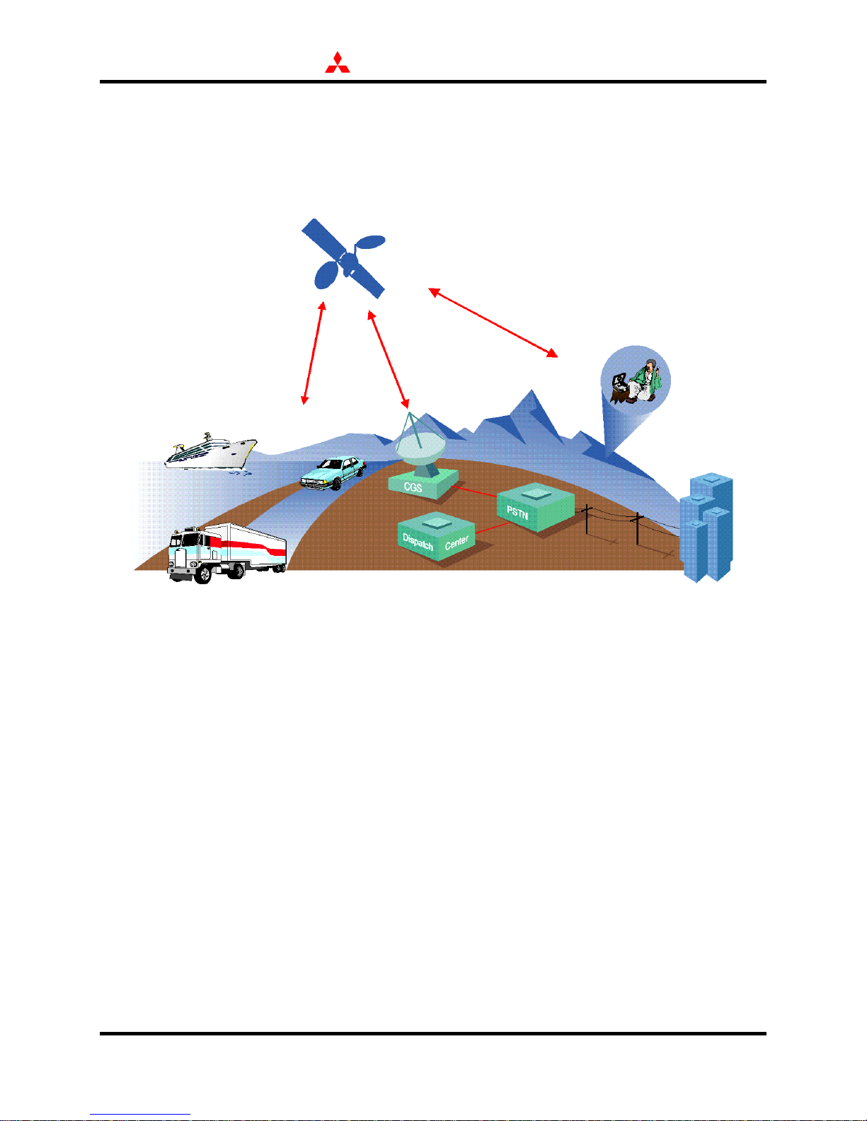
The MSAT system comprises a satellite segment, communications ground segment (CGS) and a
mobile terminal segment.
2.1 Satellite Segment
The satellite segment acts as a relay site, similar to a cellular communications base station. It
passes signals to and from the CGS and MTs. AMSC launched its satellite (AMSC-1) into
ST200 Series Technical Support Manual 1 January 2000
Page 5
MITSUBISHI ELECTRONICS AMERICA, INC.
geosynchronous orbit (~ 22,300 miles / 36,000 km altitude). The MSAT satellite is one of the
most powerful communications satellites on-orbit (>500,000 Watts) and is capable of seamless
North American and Central American coverage. Hughes Communications designed the MSAT
satellite with relatively large antennas, allowing for relatively small MT antennas.
2.2 Communications Ground Segment
The CGS routes all MT calls and provides the interface to the Public Switched Telephone
Network (PSTN). The ground segment also provides feeder communications to the satellite,
establishes channels for end-user calls, and managing system resources. AMSC’s CGS is
located at AMSC headquarters in Reston, Virginia with a backup facility located 26 miles south
of this location. TMI’s CGS is located in Ottawa, Ontario and Telecom’s CGS is located in
Mexico City.
CGS subsystems include the Feederlink Earth Station (FES), Network Communication
Controller (NCC), and Network Operations Center (NOC). The FES links the signaling channels
between the satellite and the NCC and communications channels between the satellite and the
PSTN. The NCC uses these signaling channels to manage all communication s ystem resources
through a variable number of Control Groups (CG). Each control group uses specific signaling
channels for specific MTs. The NOC oversees the entire operation, including billing and
customer service.
ST200 Series Technical Support Manual 2 January 2000
Page 6
MITSUBISHI ELECTRONICS AMERICA, INC.
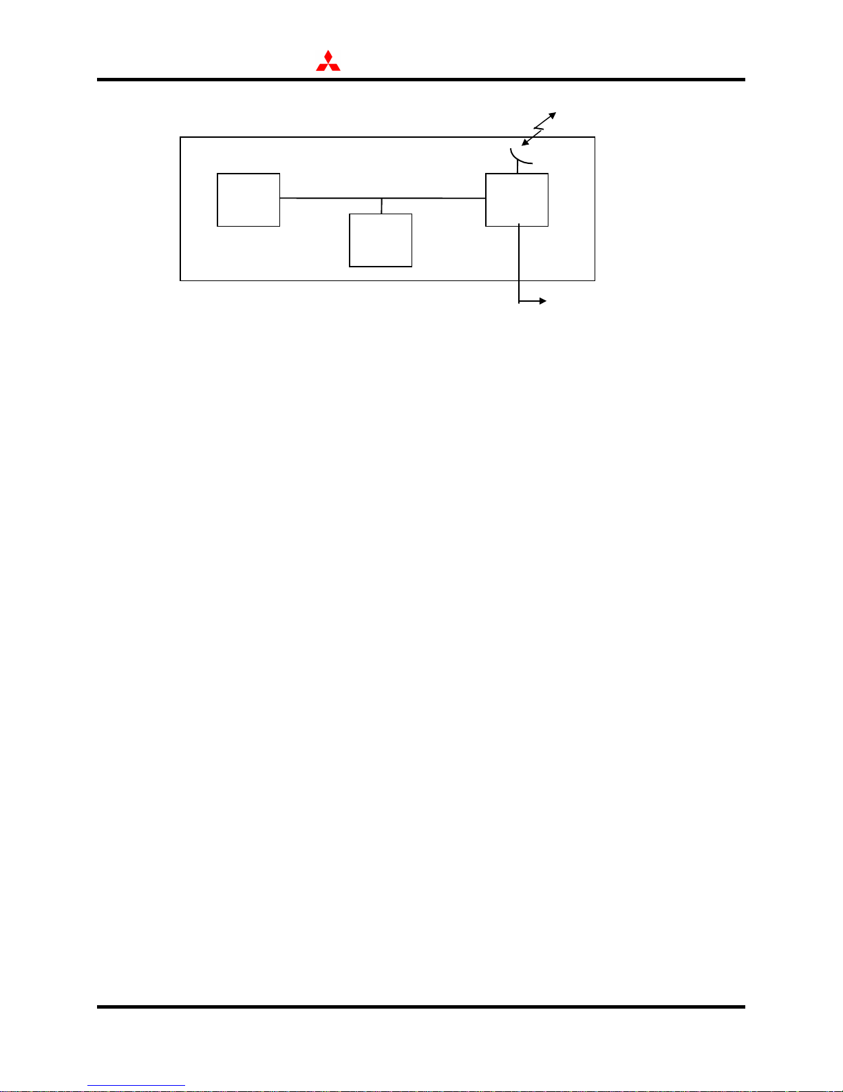
To Satellite
Communications Ground Segment (CGS)
NCC FES
NOC
PSTN
2.3 Mobile Terminal Segment
As end-user equipment, MTs transmit and receive signals to and from the CGS via the satellite.
MSAT terminals include land mobile, transportable, fixed, maritime, and aeronautical
applications. Each Mitsubishi MT comprises three functional units: Antenna Unit (AU),
Transceiver Unit (TU), and one or more user interfaces (like handsets or a personal computer).
3.0 Product Overview
3.1 General Overview
The ST211 terminal includes a transceiver, beam steering unit, and handset or user terminal
options. The beam steering unit is a small gyroscope that determines vehicle motion for mobile
satellite tracking.
The ST221M fixed site terminal comprises the same major components as the land mobile
configuration, minus the beam steering unit. The parabolic antenna in this high gain
configuration replaces the dome type antenna in the land mobile unit. The ST221M also
includes an AC/DC power supply.
Standard items and optional accessories provide basic digital voice, wide area dispatch and data
capabilities. Mitsubishi land mobile and fixed site antennas physically incorporate the radio
frequency electronics, easing installation and troubleshooting. The following figures show the
primary elements of the ST211 and ST221M configurations respectively.
ST200 Series Technical Support Manual 3 January 2000
Page 7
MITSUBISHI ELECTRONICS AMERICA, INC.
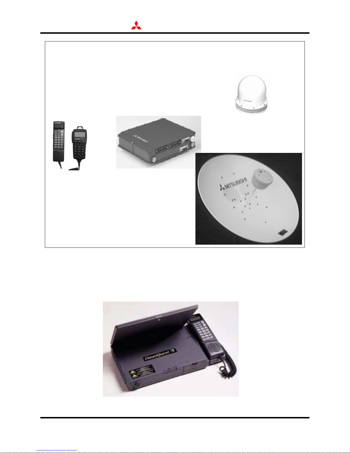
ST211
ST221M
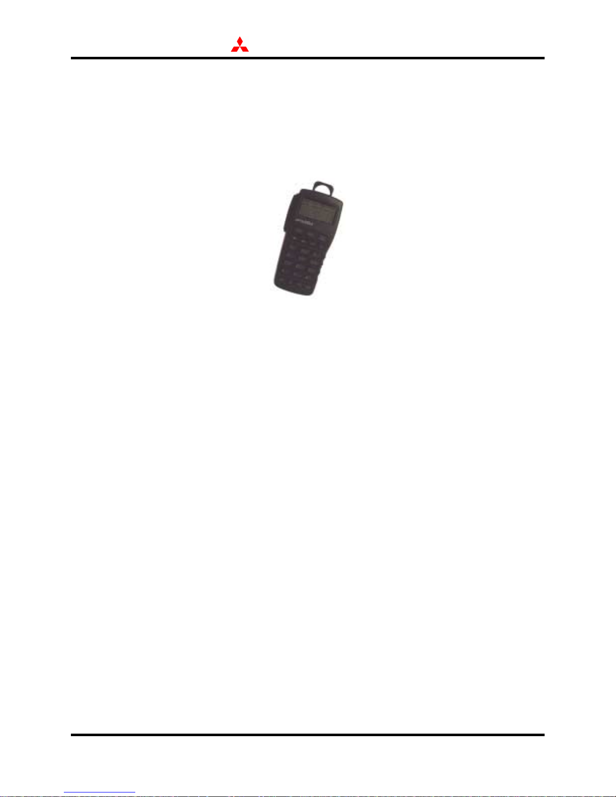
The ST251 OmniQuest® transportable terminal is one of the most versatile satellite
communications systems available to date offering many unique features and capabilities.
OmniQuest® is an integrated portable terminal containing the transceiver, antenna, battery and
handset as depicted below.
ST200 Series Technical Support Manual 4 January 2000
Page 8

MITSUBISHI ELECTRONICS AMERICA, INC.
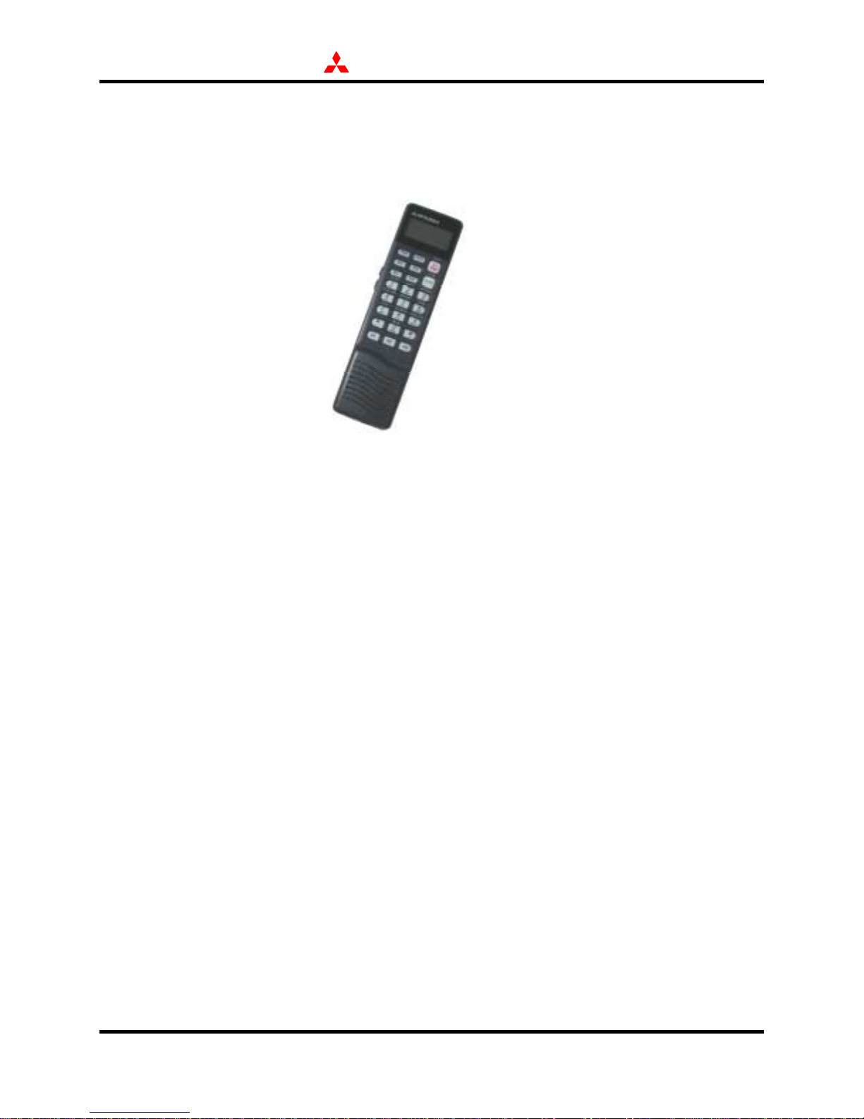
3.2 Key Features
All Mitsubishi MTs are easy to operate. The basic handset, for point-to-point calling, looks and
operates like a cellular phone. There are three one-touch speed dial keys and 99 alphanumeric
memory locations. The handset permits any key answering, displays received signal strength,
and lets users enable special features from a menu of functions. Optional accessories also allow
users to operate in a hands-free mode.
All MTs accommodate service offering for wide area dispatch with an optional push-to-talk
handset (shown above) and circuit switched data at 4800 bits per second.
Three new features have been added to these second-generation MTs: Horn Alert, Auto-PowerOn and Echo Cancellation. Horn Alert is ideal for those with Land Mobile applications who
need to be able to hear the MT ringing while away from their vehicle but while still nearby.
Auto-Power-On allows the user to set the MT to automatically power on once the vehicle’s
engine is started (just like a car radio when left on). The software–based echo cancellation
feature allows users to avoid having to install an echo canceler board in the TU.
3.3 Product Positioning
The mobile, fixed and portable terminals deliver communication where there is no existing
infrastructure; or when other systems fail or become overloaded. These MTs do not compete
with terrestrial offerings like cellular or PCS. However, for those companies and industries that
need seamless communication, Mitsubishi MTs are a viable solution. Seamless coverage and a
flat airtime rate are important for prospects who operate in multiple locations on an on-going
basis.
These MTs offer top-notch brand name recognition, reliability, and quality that Mitsubishi
supports with an in-warranty replacement program.
3.3.1 Target Markets
Mitsubishi mobile, fixed and portable configurations effectively address several niche markets:
♦ Industries that operate expansive networks like telecommunications, energy, and
utilities can more efficiently manage their field units with Mitsubishi land mobile
terminals.
♦ Remote site industries, like those involved in construction or natural resource
extraction, can employ Mitsubishi fixed site MTs for communicating with isolated
management or operation centers. This market also extends to the tourist industry
with remote hunting and fishing lodges.
♦ All configurations also address large corporations or institutions—that because of
geography or regulation—require back-up or contingency communications.
ST200 Series Technical Support Manual 5 January 2000
Page 9

MITSUBISHI ELECTRONICS AMERICA, INC.
Companies in California and Florida in the US and other locations throughout Canada
and Central America are especially receptive to this concept. Further, companies
involved in transporting or working with hazardous materials like nuclear power
generation and HAZMAT transportation must have an emergency mode of
communications.
3.3.2 Applications
Specific MSAT applications for land mobile, fixed site and portable MTs exist throughout North
and Central America today. The following examples may provide some additional insight for
sales and marketing forces. The list is not exhaustive:
♦ Telecommunications companies have pur chased land mobile and transportable MTs
for operating and maintaining land lines, both fiber optic and wire. Mitsubishi MTs
can improve the efficiency of field units responding to fiber optic cable failure, saving
a lot of money. These companies typically use dispatch service.
♦ Oil and gas companies use land mobile MTs for regular pipeline maintenance
operations. Maintenance trucks testing pressures and physical integrity throughout
the extent of a pipeline or segment of pipeline can remain in constant
communications. This concept is very similar to that employed in the
telecommunication industry.
♦ Mining and construction companies can more effectively conduct day-to-day
business from even the most remote locations. Their business may require continuous
communications with other remote sites, fleets on the road, and headquarters through
the PSTN. Day-to-day business may just entail a report at the end of each day—
either voice or data.
♦ Any large corporation in regions prone to natural disasters, like the West Coast or
Gulf States, can use MTs for contingency communications. This application is not
the same as back-up communications for conducting business operations. Rather,
contingency communications link key executives and decision-makers for
implementing already existing recovery and response plans.
♦ Hospitals, nuclear facilities, and HAZMAT trucks require some form of
emergency communications for public safety reasons. Dedicated channels or high
availability channels can save lives during emergency situations that can disable or
degrade the existing terrestrial infrastructure. As a simple example, any cellular
telephone user in a major metropolitan area knows that even a minor traffic accident
on a commuter route can saturate capacity as hurried drivers begin making calls.
More severe emergencies exponentially degrade consumer-type systems.
ST200 Series Technical Support Manual 6 January 2000
Page 10

MITSUBISHI ELECTRONICS AMERICA, INC.
4.0 Product Description
4.1 General
The land mobile MT consists of a Common Transceiver Unit (CTU), a medium gain antenna,
handset, cradle and junction box (J-box), Beam Steering Unit (BSU) and all required cabling.
The fixed site configuration also includes a CTU, handset, parabolic antenna, AC/DC power
converter, all required cabling, cradle, and junction box. The ST221M standard kit includes a 50
foot (15 meter) CTU to AU cable set. Other cable options might be available through certain
distributors.
The OmniQuest® ST251 is a complete communications terminal containing a Trans ceiver Unit
(TU), Antenna Unit (AU), Handset, Battery and an AC Adapter/Charger. The antenna unit is
conveniently mounted in the notebook lid providing a very efficient design that allows for quick
and easy setup. All standard equipment fits in the soft carrying case provided with OmniQuest®.
Optional accessories are available for all terminals for added functions and capability. Widearea or digital dispatch requires an optional Push-To-Talk (PTT) handset. Note: availability of
system features may vary based on service provider offerings. The following tables summarize
standard and optional MT components, respectively.
Standard ST211 Land Mobile MT Components
Part Number Description
TU200A CTU, Mounting Kit
AU201A AU, Mounting Kit, 18’ (5.5m) AU-TU Cable
AU1200A(S) BSU, Mounting Kit
SZ130A Cradle-3, Junction Box, Mounting Kit
SZ460A 20’ (6m) Power Cable
SZ100A Basic Handset
ST200N02 Owner’s Manual
Standard ST221M Fixed Site MT Components
Part Number Description
TU200A CTU, Mounting Kit
AU601B AU, Mounting Kit
SZ130A Cradle-3, Junction Box, Mounting Kit
PUP-55-13-J9 AC/DC Converter
FSC50 50’ (15m) AU-TU Cable Kit
SZ100A Basic Handset
ST200N02 Owner’s Manual
ST200 Series Technical Support Manual 7 January 2000
Page 11

MITSUBISHI ELECTRONICS AMERICA, INC.
Standard ST251 MT Components
Part Number Description
NT100A Base Unit (includes integrated antenna, antenna electronics and
removable transceiver unit)
SZ100A Handset w/ Curl Cord
OQ-CRADLE Cradle
SZ511A NiMH Battery Pack
SZ503A AC Adapter/Charger
ME-SN Carrying Case
ME-COM Compass
OQ-REF1 Quick Reference Card
ST251NO1 Operating Instructions
Optional Components
Part Number Description
SZ300A PTT Handset; for wide-area dispatch
FZ1283A Monitoring Speaker; for hands free operation
FZ806A External Microphone; for hands free operation
OQFAU50 Fixed Dish Antenna w/50 ft cable for OmniQuest fixed site use
OQFAU100 Fixed Dish Antenna w/100 ft cable for OmniQuest fixed site use
SZ351A Junction Box for wide-area dispatch w/OmniQuest
SZ601A Cigarette Lighter Adapter for OmniQuest
SZ511A Additional Battery for OmniQuest
ST200 Series Technical Support Manual 8 January 2000
Page 12

MITSUBISHI ELECTRONICS AMERICA, INC.
4.2 Antenna Units
4.2.1 Dome Antenna Unit
The Dome AU (AU201A) contains a single helical antenna element mounted on a ground plane
which is fixed in elevation angle and mechanically steerable in azimuth. The AU201A houses
the RF Electronics Unit (RFU) underneath the antenna. The RFU includes a high power
amplifier, low noise amplifier, diplexer, and control electronics. The antenna gain is
approximately 9 dBi, with nominally 20 Watts of L-Band RF energy (~1.6 GHz). The Dome
AU receives steering commands from the BSU, through the CTU.
WARNING: Stay 6 inches (15 cm) away from the antenna while transmitting
!
NOTE: The AU antenna cable connection at the CTU must be firmly secure prior to operation.
Loose or improper connection may render the terminal inoperable (not able to power
on) or result in error messages.
4.2.2 Fixed Site Antenna Unit
The Fixed Site AU (AU601B) is a parabolic antenna (with feed horn) which physically
incorporates the RFU, including high power amplifier, low noise amplifier, and diplexer. The
AU601B provides a gain of approximately 20 dBi and nominally emits 20 Watts in L-Band (~1.6
GHz).
WARNING: Stay 26 inches (60 cm) away from the antenna while transmitting
!
NOTE: The AU cable connections at the antenna and at the CTU must be firm l y secure prior to
operation. Loose or improper connections may render the terminal inoperable (not able
to power on) or result in error messages.
4.3 Common Transceiver Unit
The land mobile and fixed site MTs utilize a Common Transceiver Unit (CTU), the TU200A,
which provides interfaces for AUs, handsets and data devices, as well as managing signaling and
communications with the CGS via the satellite. The CTU demodulates and processes received
antenna signals; process, modulate, and send outgoing signals to the antenna for transmission;
and manages all handsets, data devices and other accessories.
In addition to providing the major MT interfaces, the CTU is comprised of a main board,
converter board and necessary power supplies. The main board multiplexes, scrambles, en codes,
and interleaves signals in addition to providing frame-formatting functions. Its logic and
signaling subsystem provides the central control of the MT to initialize self tests, setup/configure
ST200 Series Technical Support Manual 9 January 2000
Page 13

MITSUBISHI ELECTRONICS AMERICA, INC.
the CTU, handle protocols, and manage control signals and messages with handset(s) and data
devices. A logic and signaling processor in the main board includes a CODEC for anal og and
digital conversions of voice signals. The CTU converter board contains the necessary frequency
synthesizers, up and down converters, and the QPSK modulator.
The most current CTU configuration accommodates 4800 bits per second data communications,
a satellite acquisition algorithm that speeds network access, and advanced service features. The
availability of advanced service features depends on the specific offerings of each service
provider, but can include:
♦ Call Line Identification (Caller ID) and Caller ID Restriction—Handset displays
the caller’s phone number or protects your phone number from such devices
♦ Connected Line Identification and Connected Line Restriction —Handset displays
the phone number of the party who you called or protects your phone number
from such display
♦ Call Transfer—Transfers a call in progress to a third party without any previous
connection
♦ Call Forwarding and Voice Mail—Forwards incoming calls to another number
(without ringing) or to a voice mailbox when your phone is busy or unattended
♦ Call Waiting—Notifies the user of an incoming call during a conversation and
allows switching between these calls
♦ Conference Calling—Allows conversations with several parties simultaneously
♦ Call Barring—Restricts placing one or more types of calls
♦ Alternate Account Charging—Allows billing to specific accounts for particular
phone calls
♦ Enhanced Fraud Protection—Requires a four digit PIN, that the service provider
assigns, to complete dialing
4.4 CTU Cradle and Junction Box
The cradle and junction box provide the appropriate interfaces for the basic handset and
accessories with the CTU. The handset cradle package (SZ130A) includes a clip mount with an
RJ-45 handset interface and the junction box (SZ350A) interface for accessories (PTT handset,
monitoring speaker, and hands free microphone).
ST200 Series Technical Support Manual 10 January 2000
Page 14

MITSUBISHI ELECTRONICS AMERICA, INC.
NOTE: All connections between the basic handset and the CTU must be firmly secure. Loose
or improper connections may render the terminal inoperable (not able to power on) or
result in error messages.
4.5 Beam Steering Unit
The Beam Steering Unit, or BSU (AU1200A), is a small component that attaches to the side of a
CTU in the land mobile configuration. Its piezo-electric gyroscope and control system sense
changes in vehicle direction. The BSU feeds these measurements directl y through the CTU to
the antenna for closed loop tracking. The CTU also processes this information for optimizing its
system management functions. Section 5 includes additional information on antenna pointing.
The BSU must be mounted within + 5o of vertical (relative to the ground) for proper operation.
For rapid satellite acquisition and lock, the vehicle should remain stationary or move along a
straight path for the first ten (10) seconds of MT operation.
4.6 CTU Power Components
The power cable (SZ460A) connects from a vehicle’s 12 Volt battery line directly to the CTU in
a land mobile configuration. The power cable has a +12V power line, a +12V ignition sense
line, and a ground line. The power and ignition sense lines each contain a 10A in-line fuse
which protects the CTU and the vehicle’s electrical system.
The PUP-55-13-J9 AC/DC converter provides 13.8 V at 55 Watts of continuous output power to
the fixed site ST221M. This unit is enclosed in a polycarbonate case with an IEC320 inlet
connector, which allows interchangeable power cords for international use. All models meet
VDE class B and FCC class B emissions limits, and are approved to UL, CSA, and CTUV safety
standards.
4.7 OmniQuest® Description
A brief description of each of the main components of OmniQuest
®
is provided below.
4.7.1 Base Unit
The OmniQuest
®
Base Unit (NT100A) houses all of the main electronics of the system including
the Antenna, Radio Frequency Unit (RFU), removable Transceiver Unit (TU), and power
electronics (including internal battery). Latches are included to secure the antenna and TU and a
release lever secures the battery pack when the door is open.
NOTE: The TU and the battery are the only removable sub-assembli es in the OmniQuest®. The
electronics contained in the RFU (within the NT100A unit), the antenna lid and the
TU201A subassemblies are not serviceable outside MELA’s service center.
Distributors and their agents should not attempt to access these electronics unless
authorized by MELA (does not apply to Battery Pack).
ST200 Series Technical Support Manual 11 January 2000
Page 15

4.7.1.1 Antenna
MITSUBISHI ELECTRONICS AMERICA, INC.
The integrated lid Antenna receives signals transmitted from the satellite and transmits signals
provided from the RFU. The OmniQuest
patch antenna integrated into the lid and connected to the OmniQuest
®
Antenna is comprised of a two element planar array
®
Base Unit. The antenna
provides a gain of approximately 10.8 dBic and emits 20 Watts of RF energy nominally in the L
Band frequency range (~1.6 GHz).
WARNING: Stay 2 feet (24”) / 61 cm away from the antenna while transmitting
!
The OmniQuest
®
antenna must be manually pointed at the satellite which is aided by using the
Quick Reference Card and compass provided in the standard carrying case. Because the
beamwidth of the antenna is fairly wide (~30o), approximate pointing of the antenna is easy.
Once the approximate location of the satellite has been established, the pointing angle can be fine
tuned by using the Received Signal Strength Indicator (RSSI) displayed on the Handset (i.e.,
approximate or initial pointing of the satellite needs only to be accurate enough so that a signal
can received on the RSSI). See section 5.11 for operational considerations concerning the RSS I
and OmniQuest
®
setup.
NOTE: If an approved external antenna is used, the cable must be securely attached to the
RFU prior to operation. Likewise, if switching from an external antenna back to the
OmniQuest
®
self-contained antenna, the antenna cable must also be securely at tached.
Loose or improper connections may render the terminal inoperable (not able to power
on or low received signal) or result in error messages.
4.7.1.2 RF Unit
The RFU is contained within the Base Unit and provides an interface between the Omni Quest
antenna and the removable TU. The RFU contains a High Power Amplifier (HPA), Low Noise
Amplifier (LNA), diplexer, and control electronics that provide the proper amplification,
filtering, and control of the RF signals generated from the TU and received from the satellite
through the antenna.
4.7.1.3 Transceiver Unit
The removable TU201A Transceiver Unit is located inside the Base Unit, providing the
necessary interfaces for user devices and the RFU, as well as managing all signaling and
communications with the CGS via the satellite. It demodulates and processes the signals
received by the antenna through the RFU; processes, modulates, and sends signals to the RFU
for transmission, and manages all interfaces with user interface equipment, other connected
accessories, and network interfaces with the CGS.
NOTE: All required interfaces for the OmniQuest
®
Transceiver Unit are available on the TU
connector panel. Distributors should not attempt to access the electronics inside the
Base Unit without prior authorization from MELA.
®
ST200 Series Technical Support Manual 12 January 2000
Page 16

MITSUBISHI ELECTRONICS AMERICA, INC.
NOTE: The connection of the TU to either the Base Unit or the TMU must be firmly secure.
To ensure proper connections after inserting the TU into the Base Unit, adjust latches
(located on BOTH sides of the Base Unit) to the “L” or locked position.
4.7.2 Battery Pack
The SZ511A Battery Pack provides DC voltage for operating the OmniQuest® MT. The Battery
Pack is comprised of NiMH Battery cells (similar to some cellular telephones) and provides for
the storage of energy to provide DC powe r (see speci fic ati ons for rat ings). T he Battery Pack can
be charged through use of the AC Adapter/Charger from an ex ternal 115 VAC / 60 Hz power
source while installed in the OmniQuest® Base Unit or when removed as discussed below.
NOTE: There are several handling, storage, and charging considerations for increasing the
performance and lifetime of NiMH Battery Packs. Please refer to the ST251 Operating
Instructions for details.
NOTE: The standard Battery Pack is rated to provide for > 1 hour of talk time at 77oF / 25oC.
Because the MT is voice activated, the typical conversation time obtained from a fully
charged Battery Pack could be > 2 hours.
NOTE: There are several operational considerations concerning batter y run time, which should
be well understood by the users. Please refer to the ST251 Operating Instructions or
section 5.11 for details.
NOTE: This Battery Pack has been designed specifically for use and operation with the
OmniQuest® ST251 MT. Do not attempt to use other batteries with this unit.
4.7.3 OmniQuest®AC Adapter/Charger
The SZ503A AC Adapter/Charger provides two methods for charging the Battery Pack as well
as providing DC power output for operations. The DC output cable of the AC Adapter/Charger
can be used for trickle charging a battery pack installed in the OmniQuest® MT and/or for
powering the MT during operation when connected to the DC Input Connector of the MT.
Alternately, the Battery pack can be removed from the MT and attached directly to the unit for
charging. Rapid charging of the battery takes approximatel y 2 hours. When the MT is powered
on and in transmit mode, rapid charging changes to trickle charging and may take up to 24 hours
if the MT is continuously transmitting (e.g., in data mode).
NOTE: When the battery pack is fully charged, the indicator light on the SZ503A will change
from red to green (for either the “spa re” batter y pack or the “main” b attery pack i nside
the base unit). Prompt removal of the battery is required to avoid overcharging, and
potential damage to the SZ511A battery pack.
The DC output cable of the SZ503A is approximately 1 foot (32 cm) in length and is hard wired
directly to the AC Adapter/Charger. The plug at the end of the DC output cable is a special 4-pin
connector which mates to the DC Input connector of the Base Unit. The AC input cable for the
AC Adapter/Charger is approximately 6 feet (1.8 m) in length. The c ylindrical objects attached
ST200 Series Technical Support Manual 13 January 2000
Page 17

MITSUBISHI ELECTRONICS AMERICA, INC.
to the cords are special inductive filters and are required to maintain compliance with FCC
requirements for conducted emissions. No attempt should be made by distributors or users to
fabricate replacement or alt ernate cables, to modify the length of these cabl es, or to remove or
change the filters on the cables.
NOTE: The AC Adapter/Charger has been designed specifically for the OmniQuest® ST251.
Only this unit should be used to provide power to the MT for operation or to charge the
Battery Pack from an AC power source.
4.7.4 Standard Carrying Case
The Standard Carrying Case provides space to accommodate all of the standard components of
the OmniQuest®, and AC Adapter/Charger. Also provided with the Standard Carrying Case is a
magnetic compass and a Quick Reference Card to assist in setup. The Standard Carrying Case is
constructed of 600 denier nylon with reinforced seams.
NOTE: The Standard Carrying Case only provides light protection to the OmniQuest
components from moisture and impact. The user is responsible for ensuring that the
OmniQuest® components are protected to a level consistent with the users specific
operating and transportation environment.
4.7.5 OmniQuest® Cigarette Lighter Adapter (CLA)
The SZ601A Cigarette Lighter Adapter (CLA) provides a method to supply 9.6V DC input to the
MT from a standard 12V vehicle cigarette lighter socket. The CLA cables are similar in length
to the AC Adapter/Charger cables. The CLA is functionally equivalent to the AC
Adapter/Charger and can both power the OmniQuest® unit and charge a battery while installed in
the OmniQuest® unit or when installed on top of the charger.
NOTE: The SZ601A CLA has been designed to meet the specific voltage requirements of the
OmniQuestTM ST251. Only the SZ601A should be used to provide power to the MT for
operation or to charge the SZ511A Battery Pack from a standard cigarette lighter
socket. Use of other CLA adapters may void the ST251 limited warranty.
4.7.6 OmniQuest® Junction Box
Only OmniQuest® specific Junction Boxes (SZ351A, SZ352A) are designed to work with the
ST251 terminal. Both Junction Boxes provide the capability of using the PTT Microphone and
allow the use of hands-free accessories (i.e. external speaker, microphone). The SZ352A
Junction Box includes a longer cable and is therefore more suitable for permanent vehicle
installations or if the customer desires a longer cable. The Junction Box connects to the “J-Box”
port of the OmniQuest® TU. For hands-free operation, the user connects the hands-free
microphone and speaker to the junction box.
®
NOTE: Although the handset contains an external speaker which will provide hands-
free/dispatch audio, the external speaker is a desirable and highly recommended option
if the handset speaker is not loud enough or a remote location of the speaker is desired.
ST200 Series Technical Support Manual 14 January 2000
Page 18
MITSUBISHI ELECTRONICS AMERICA, INC.
In most cases, the customer will prefer the external speaker for dispatch and hands-free
operation. To activate hands-free mode, the handset must be connected to the TU and securely
latched into the handset cradle. The handset cradle contains a magnet that deactivates the
handset speaker and activates the external speaker when connected to the Junction Box.
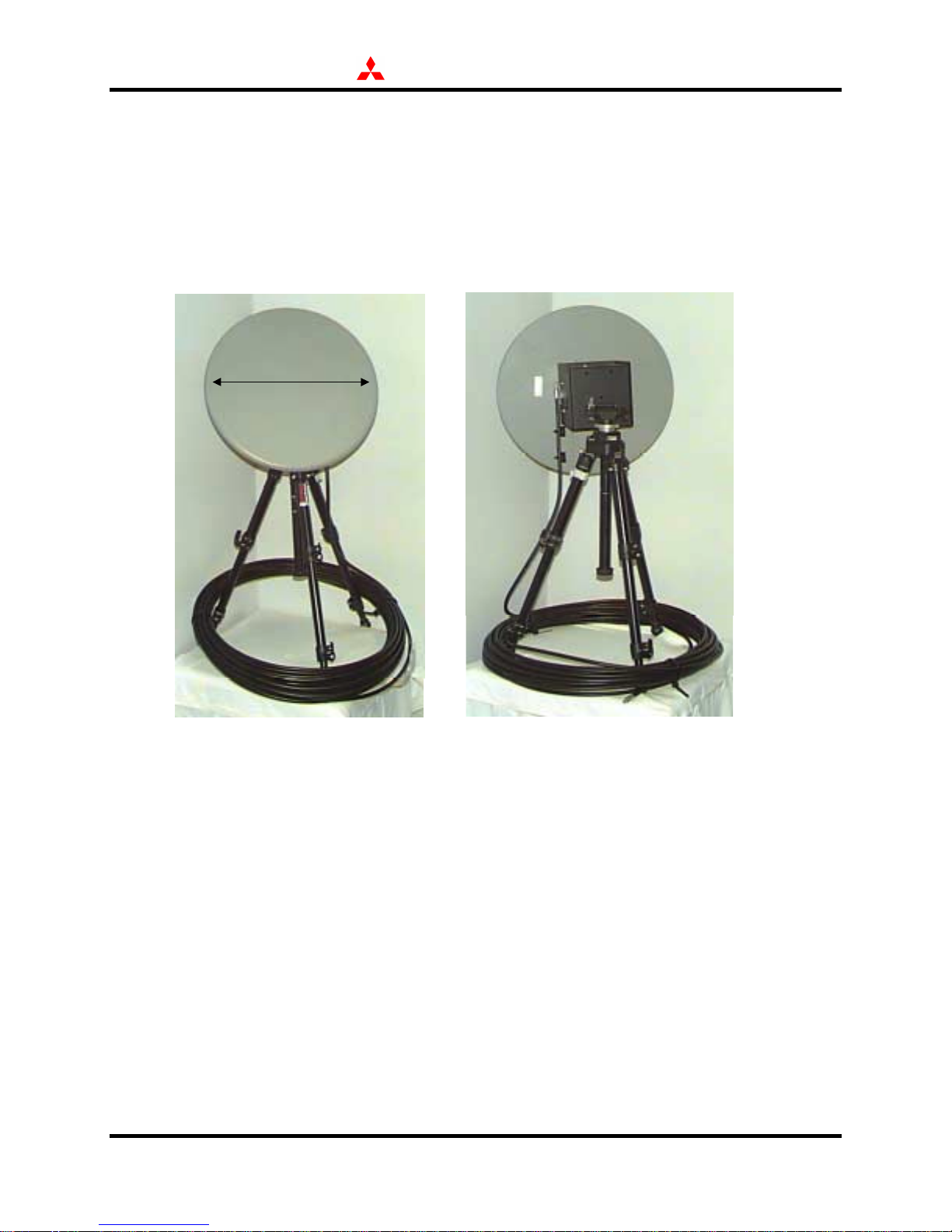
4.7.7 OmniQuest® Fixed Dish Antenna
External antenna
18”
(OQFAU) shown with
100’ cable (Type
LMR400) and
optional tripod.
Weight of ant enna
and mounting
hardware is
less than 5 lbs.
See Appendix C for
detailed installation
instructions.
OmniQuest® is capable of being operated with an external Fixed Dish Antenna (OQFAU50)
connected to the RFU through the external ant enna port (located on th e back of the OmniQuest
base unit). The Fixed Dish Antenna is 18” in diameter and comes with mounting hardware and
50 feet of cable (LMR240). A 100’ cable may also be used and is commercially available. The
cable type needed is LMR400 and requires SMA straight connectors. The OQFAU50 is fully
weatherproof and “marinized” for use in harsh or salt water environments. For temporary fixedsite applications, use of a tripod is desirable, however, the OQFAU50’s mounting b racket will
also accommodate a 2” diameter mounting pole.
4.8 Basic Handset
The standard handset (SZ100A) operates as a control panel for dialing and storing phone
numbers and accessing built-in functions. The handset has a two line, seven character liquid
crystal display (LCD) and a 23 button keypad (illuminated). The keypad control panel has a
standard 12 button alpha-numeric telephone keypad (most with multiple functions), 3 speed
ST200 Series Technical Support Manual 15 January 2000
®
Page 19
MITSUBISHI ELECTRONICS AMERICA, INC.
dialing keys, and eight other unique keys including a power button and two volume control
buttons on the side of the handset. Users can input up to 28 characters or numbers for placing a
call or memory storage in one of 99 locations (two screens required to see the entire location).
The interface between the standard handset and the cradle is a special 8-wire interface using RJ45 connections. The interface consists of three audio lines, two serial data lines, a power-on
signal line, +12V DC power, and ground. The serial data lines transmit keypad strokes and
receive and display commands from the handset and CTU.
The curl cord stretches to a maximum length a 5 feet (1.5m). Do not attempt to fabricate a
replacement or alternate cable, or modify the length of the curl cord provided. Although
standard RJ-45 extension cables exist, Mitsubishi Electronics does not endorse these extension
cables or guarantee MT product performance and reliability with these cables.
The connection of the Handset curl cord at the cradle must be firmly secure. Loose or improper
connections may render the terminal inoperable (not able to power on) or result in error
messages.
4.9 Push-to-Talk Handset
The Push-To-Talk handset, or PTT microphone, is an optional accessory providing access to the
wide-area dispatch service known as net radio. The PTT handset lets users select up to 15
different networks, or talkgroups. The MSAT service provider configures these channels, which
operate in a half-duplex manner like a standard two-way radio. The PTT handset also allows
users to automatically scan through configured talk groups and select active networks. The PTT
handset plugs into the junction box with the optional external speaker (needed for received
audio).
The interface between the PTT handset and the junction box is a special 8-wire interface using
RJ-45 connections. The interface comprises one audio line, two serial data lines, a PTT signal
ST200 Series Technical Support Manual 16 January 2000
Page 20
MITSUBISHI ELECTRONICS AMERICA, INC.
line, a power-on signal line, +12V DC power, and ground. The serial data lines transmit keypad
strokes and display commands to/from the transceiver.
The PTT handset must be securely connected to the junction box prior to power-on of the MT.
Net radio operation also requires an external monitoring speaker.
4.10 Other Accessories
Other accessories such as Mitsubishi hands free microphones and ex ternal speak ers a re available
through equipment distributors. Customers should contact these distributors directly concerning
cost and availability.
5.0 Product Operation
Mitsubishi satellite telephones are user friendly, operating like a cellular phone (i.e., no dial tone)
and requiring minimal user interaction. These MTs have many built-in features including special
function keys, user programmability options, and security features. This section includes a brief
design overview as useful background for understanding MT operations.
5.1 Design Overview
The Mitsubishi MTs operate under a blanket license from the FCC for MSAT Service under Part
25 (Satellite Communications) of its rules. This license, on file with the FCC (File No. 2823DSE-P/L-93), does not require special MT identification tags for compliance. The fixed site
MT, ST221M, also complies with Part 15 of the FCC Rules as a Class B unintentional source of
radiation subject to the conditions thereunder. The land mobile MT has no requirement for Part
15 compliance.
The MSAT network operates in the L-Band of the frequency spectrum, roughly covering 1.5-1.6
GHz. Because L-Band signals are subject to fading, Mitsubishi MT design includes additional
margin to assure performance and reliability. The terminals’ digital modulation and signal
ST200 Series Technical Support Manual 17 January 2000
Page 21
MITSUBISHI ELECTRONICS AMERICA, INC.
processing techniques also minimize fading effects to a level that outperforms analog cellular
and standard two-way radio systems.
The mean time between failures for the land mobile and fixed site MTs is greater than 5200
hours of continuous use—actual performance may exceed this design value.
: WARNING: MT operation may interfere with inadequately protected medical devices,
!
including pacemakers. Consult a physician or the manufacturer of the medical device
with any questions.
Changes or modifications to the equipment that Mitsubishi Electronics does not expressly
approve can void the authority to operate equipment within commercial and residential
buildings.
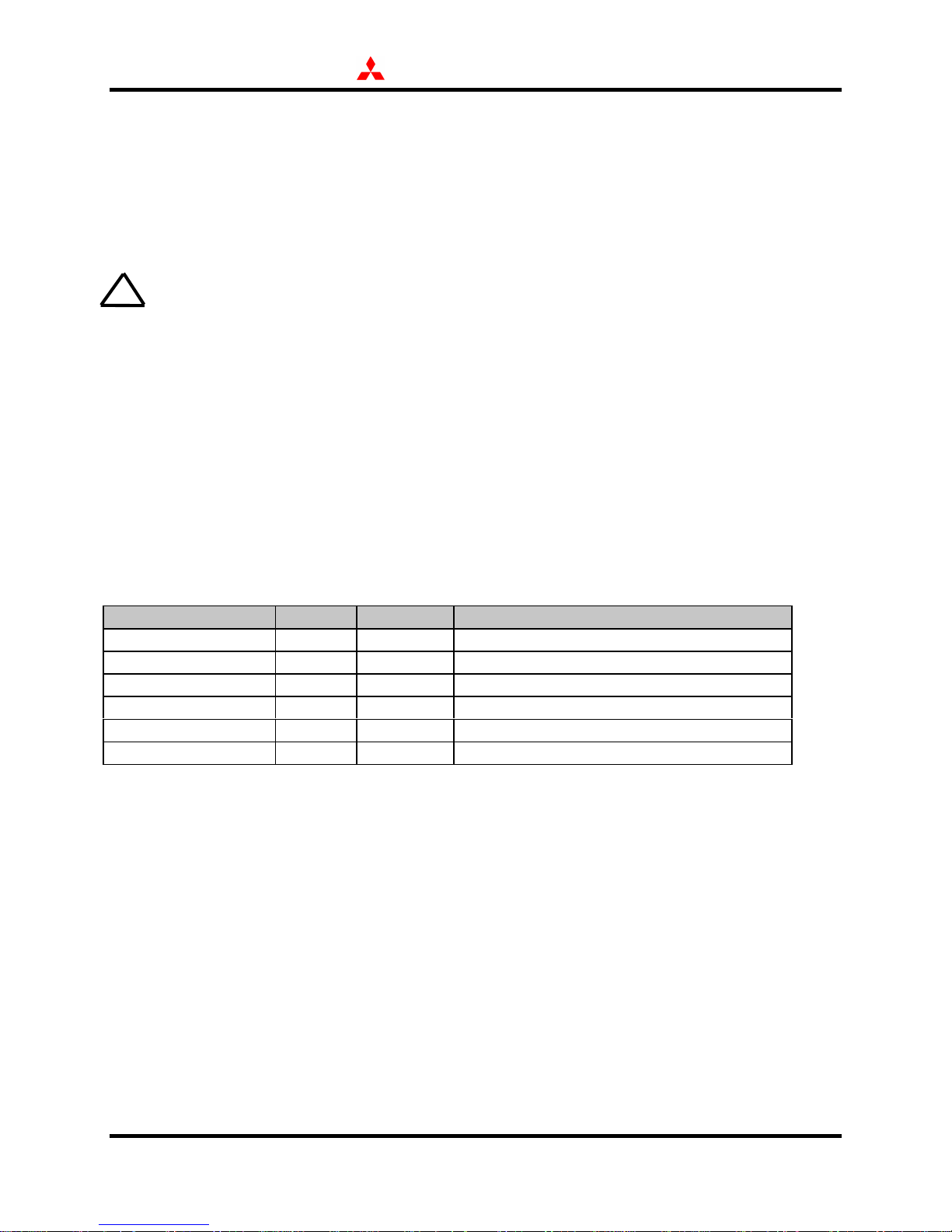
5.2 Signaling and Communications Channels
All Mitsubishi MTs access the MSAT network through six different special “channels”. The
following table defines these channels:
Channel From To Purpose
Pilot Signal CGS MT Reference signal for acquisition
GC-S Channel CGS MT System status, call indication, commands
MET-ST Channel MT CGS Responses to CGS commands
MET-SR Channel MT CGS Call setup and other requests
FES-C Channel CGS MT Communications, in-band signaling
MET-C Channel MT CGS Communications, in-band signaling
5.2.1 Pilot Signal
The MSAT satellite continuously transmits an L-band pilot signal in each of five regional
coverage beams. The MT’s pilot signal strength (initially displayed on the handset) serves as a
reference for locating the satellite before initiating the GC-S acquisition process. The pilot
signal itself does not, however, carry any information.
5.2.2 GC-S Channel
The Group Controller-Signaling (GC-S) channels provide network status information, incoming
call indications, and control messages from the CGS to the MT. The MSAT network can
accommodate up to 16 GC-S channels per beam, per control group (see section 2.2). An MT
ST200 Series Technical Support Manual 18 January 2000
Page 22

MITSUBISHI ELECTRONICS AMERICA, INC.
selects one GC-S channel, based upon the last channel used and current network conditions.
Multiple terminals can share this GC-S channel using a Time Division Multiplexing (TDM)
scheme. The GC-S provides information to MTs when they are idle—logged onto the network
but not engaged in a call. Each MT has an encrypted Forward Termi nal Identification Number
(FTIN) as an address for the GC-S channel , protecting all com munications. The received signal
level of the GC-S channel is displayed on the handset after an idle MT completes network
acquisition.
5.2.3 MET-ST Channel
MTs respond to GC-S information and commands through the MET-ST channel. Based on
traffic conditions, the ground segment will assign a specific number of MET-ST channels to each
GC-S channel. The TDMA channel structure is at some fixed time slot following a GS-S
request/command. A unique Reverse Terminal Identification Number (RTIN) identifies METST messages—the RTIN is equivalent to the Electronic Serial Number for each MT.
5.2.4 MET-SR Channel
The MET-SR channel transmits unsolicited MT requests to the ground segment such as call
setup, and beam log-on. Each control group (see Section 2.2) can have up to 64 MET-SR
channels. Access to the MET-SR channels is on an as-needed basis using a “Slotted A LOHA”
protocol. This protocol selects an available MET-SR channel at random, transmits its message in
the next available time slot, and then waits a specific amount of time to receive an
acknowledgment from the ground segment (over the GC-S channel). If an acknowled gment is
not received in the proper time frame the MT will wait a random amount of time and then
attempt to re-transmit the message. The MT also receives information from the ground segment
on the MET-SR channels that help in congestion control. The RTIN also identifies messages
from the MT to the ground segment on these channels.
5.2.5 MET-C Channel
The MET-C channel transmit (1) voice and data communications from the MT to the ground
segment and (2) in-band signaling. The ground segment assigns the channel to a specific MT
(over the GC-S channel) in response to a call setup request (over the MET-SR chann el). The
MET-C channels use Single Channel Per Carrier (SCPC) / Frequency Division Multiplexing
Access (FDMA). This means that each channel occupies its own dedicated 6 kHz of spectrum
during a call. The MET-C channel is voice activated, only transmitting when voice or data bits
are present. During an active call, the channel includes multiplexed in-band signaling messages
for network management and call control functions like on-hook and connect acknowledgment.
5.2.6 FES-C Channel
The FES-C channel sends (1) voice and data calls and (2) in-band signaling to the MT, from the
ground segment. The ground segment assigns the FES-C channel (via GC-S channel) to an MT
ST200 Series Technical Support Manual 19 January 2000
Page 23
MITSUBISHI ELECTRONICS AMERICA, INC.
in response to a call setup request (over the MET-SR channel). Like the MET-C channel, FES-C
channels also use SCPC/FDMA access in a dedicated 6 k Hz, voice activat ed slot. Likewise this
channel also includes multiplexed in-band signaling messages for network management and call
control functions like ring command and on-hook command.
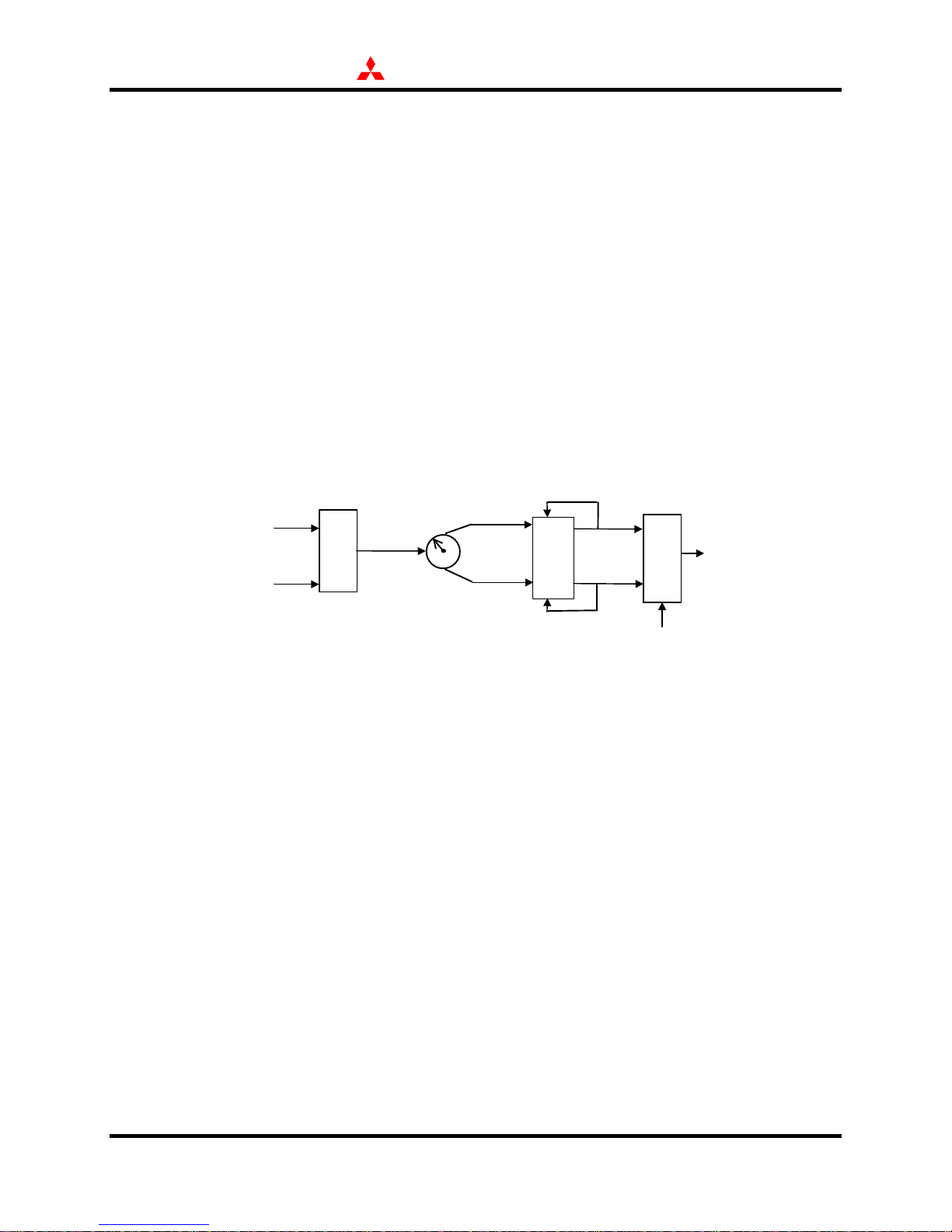
5.3 Modulation & Encoding
The digital bit stream containing voice call, data call, and command information are Differential
Quaternary Phase Shift Keying (DQPSK) modulated onto the L-Band RF carrier. Phase Shift
Keying is a popular digital satellite modulation technique which assigns (and transmits) a
specific phase of the carrier frequency to the value of the sample period. For QPSK there are
four phase values that correspond to two bits of sampled data. In differential QPSK, the phas e is
also encoded with a binary algorithm or logic, like XOR or AND functions. This figure below
illustrates differential encoding and modulation functions.
Processed Digital Voice
or Data Bits
Processed Signaling Bits
M
U
X
Odd Bits
Even Bits
n
c
o
d
e
r
e
I (n)
Q (n)
o
d
u
l
a
t
o
r
m
L-Band RF
at Phase x
(x=+45,+135,-45,-135o)
L-Band RF Carrier Signal
The MET-SR and MET-ST channels use binary Differential Phase Shift Keying (DPSK)
modulation, where only two phases (+90o, -90o) correspond to the bit values 1 and 0. The
demodulators for each channel type reconstruct the bit encoded bit stream described above.
5.4 Signal Processing
Prior to modulation on the transmit side and after demodulation on the receive side, the MT
digitally processes the actual voice, data, and signaling to improve performance and enhance
privacy. These following sections briefly review these processing methods. For a complete
discussion of privacy and security capabilities, see Section 5.5.
5.4.1 Scrambling
All digital voice and data bits, as well as signaling messages, are scrambled before being
encoded and modulated for transmission to ensure privacy. The scrambler is a Pseudo-Noise
(PN) scrambler with a 15-stage shift register. During each bit cycle, the output of the 15-bit shift
register adds to the incoming information bit, resulting in the output bit. The output of the shift
register derives from some binary combination (e.g. XOR, AND, etc.) of the resident 15 bits,
with results feeding back into register during each cycle. This process continuously changes the
ST200 Series Technical Support Manual 20 January 2000
Page 24

MITSUBISHI ELECTRONICS AMERICA, INC.
scrambling bit. Since the MT randomly selects the initial contents of the shift register (starting
each scrambling process) the output is also random. The MT and ground segment can scramble
and de-scramble the communications link because the MT transmits the initial scrambling
pattern to the ground station.
5.4.2 Interleaving
Interleaving is a process by which the information bits to be communicated are “shuffled” in
some organized manner. Interleaving improves performance on the digital link by mixing up the
bits such that if a short fade or blockage of the signal results in the loss of some bits, they would
end up being widely dispersed in the received information bits after they are deinterleaved,
resulting in little or no impact. The interleaver used in the MT is a block interleaver in which
data is read into the interleaver by rows and then taken out of the interleaver by columns, thus
mixing up the bits in a structured way. The interleaver is only used on data bits and signaling
bits (digital voice bits are not interleaved) and the block size of the interleaver (i.e. number of
rows and columns) is different depending on the operating mode.
5.4.3 Forward Error Correction
Forward Error Correction (FEC) also improves communications performance for the data and
signaling bit—the CODEC performs FEC for voice bits. The MT uses convolutional encoding,
where two or more bits are transmitted for each original bit based upon the contents of a shift
register. Specifically, the MT uses a 1/2 rate en coder of constraint length K=7. Therefore the
MT convolutional encoder produces two output bits based on the summation of the last seven
bits. The technique, called Viterbi decoding, re-assembles the information into its most likely
original form.
5.5 Security Functions
5.5.1 Electronic Features
Mitsubishi MTs, including land mobile and fixed site configurations, offer five key electronic
security features:
♦ Handset Lock Code
♦ Security Code
♦ Call Restriction Levels
♦ Authentication
♦ Communications Scrambling Vector
The basic handset has a user programmable 3-digit lock code. W hen locked the handset can not
place or receive calls, except for 911 (or other emergency numbers in the Number Assignment
Module, or NAM). Regular use of the handset lock will significantly mitigate the risk of
unauthorized users.
ST200 Series Technical Support Manual 21 January 2000
Page 25

MITSUBISHI ELECTRONICS AMERICA, INC.
A 4-digit security code allows users to set call restrictions, change the 3-digit handset lock code,
reset an accumulated talk timer, and change the status monitor. Users can input their 4-digit
security code into the MT during NAM programming. Call restriction levels include: no
restriction, recall memory locations 1-99 only, and receive only.
The MT saves both the handset lock and the call restriction mode settings while off. For
maximum security, users should electronically lock the handset or select receive only call
restriction.
5.5.2 Authentication
Every MT authenticates its identity upon call setup and during commissioning and performance
verification tests. The authentication process encrypts a random variable and an Access Security
Key (ASK) to form an authentication code. The MT and CGS independently generate the
authentication code, with the MT sending its version of the code to the CGS at the beginning of
each call event. The CGS in turn verifies that the MT can continue call setup, commissioning, or
performance verification tests. The authentication code is both random and e ncrypted for each
event, with only the specific MT and CGS having all information required to produce the code.
5.5.3 Scrambling
All communications between a specific MT and the CGS are scrambled before transmission.
Because the scrambling function derives from a random number that each MT selects, only that
specific MT and the CGS can de-scramble intelligible communications.
5.6 Network Data Distribution & Storage
During initialization, and each time the MT is powered on, the CGS transmits network data to
that MT. This data includes network status, channel parameters, and signaling channel
assignments. The MT stores some of this data in Non-Volatile Random Access Memory
(NVRAM), retaining the information when powered down. For example, an MT saves the
system table in NVRAM, defining the last beam and signaling channel used. The system table
helps the MT in the network acquisition process. The CGS continuously transmits detailed
system status and assignment information to operating MTs through the GC-S channel (idle MT)
or FES-C in-band signaling (active MT).
5.7 Shutdown Conditions
There are four conditions that may cause a MT to cease transmission or automatically shut down.
All dealers should be aware of and understand these conditions for trouble resolution and user
training.
ST200 Series Technical Support Manual 22 January 2000
Page 26

MITSUBISHI ELECTRONICS AMERICA, INC.
♦ System Deactivation
♦ Low Power
♦ Temperature Alarms
♦ Loose or Disconnected Cables
System deactivation is when the CGS commands the MT to deactivate (handset display: Shut
Down) due to network congestion, MT failure of a performance verification test, detection of
corrupt NVRAM, or the need for excessive re-transmissions to successfully deliver messages. It
is also possible that the Aeronautical Mobile Satellite Service (AMSS) may exercise its priority
access rights in emergency situations. In these cases the dealer must coordinate with the MSAT
service provider to request reactivation. This situation may also require re-commissioning.
An MT may automatically shut itself down if it detects low power or high temperatures. In both
cases the MT notifies the user of the situation with an audible warning tone prior to automatic
shutdown. In most cases the user can terminate a call in progress before automatic shutdown.
Finally, an MT may power down or not be able to power on if there are loose or disconnected
cables. Proper MT operation requires secure connections between the handset, CTU, and AU.
Damage to cables may also cause the power-off condition.
5.8 Operation
5.8.1 Initialization
The Mitsubishi MTs run through a hardware and software self-test procedure every time a user
applies power. The MT will request programming information the first time that it powers up.
After programming, described in Section 7, the unit will automatically power down. When the
user powers up again, the MT will request the Pilot Frequency Code (PFC) and the
Commissioning Frequency Code (CFC), which the dealer obtains from the MSAT service
provider. These codes identify the pilot channel frequency (for satellite location) GC-S channel
frequency (for commissioning messages). The land mobile MTs can now find the satellite and
begin commissioning. Fixed site and transportable MTs require manual antenna pointing
towards the satellite. This setup procedure is described in the following section (5.8.2).
The commissioning procedure automatically starts after the user responds to the push SEND
button prompt from the MT. The initialization request from the MT goes over a special METSR channel to the CGS. The CGS then verifies that the MT is registered and sends a response,
including initial assignment and identification information. The CGS then commands the MT to
perform a Performance Verification Test (PVT) including both the signaling and the
communications channels. For communications channel testing, the MT enters a loopback
mode, sending data to the NCC for checking errors. After the MT successfully completes the
PVT, the NCC sends a commissioned indication to the MT, indicating that it is ready for service.
ST200 Series Technical Support Manual 23 January 2000
Page 27

MITSUBISHI ELECTRONICS AMERICA, INC.
5.8.2 OmniQuest® Setup
Upon power up, the ST251 MT runs through a self-test procedure to check the inte rnal status of
hardware and software. If no internal faults are detected, the unit will prompt the user to point
the TPB antenna towards the satellite and then to press * to initiate automatic GC-S selection.
During automatic GC-S selection, the MT selects a GC-S channel based upon information stored
in NVRAM about the status of the MSAT system when the MT was last logged on. The MT
searches GC-S channels in an organiz ed manner starti ng wi th t he GC-S chann el wi thin the beam
which was last used and then moving on to others if this channel or beam is not available (based
on signal strength and error rates). If the MT has been moved to another beam area since it was
last operated, it must also perform a log-on procedure to notify the CGS about which CGS
channel it is using (within a specific beam). Once a log-on response is received from the CGS,
the MT is available for calls and the NO SVC indicator on the handset should turn off.
5.8.3 Placing a Telephone Call
To place a voice call, the user dials the telephone number on the keypad, or recalls a number
from a memory location, and then presses the send button. Pressing speed dial keys, P1-P3,
performs both telephone number input and send functions. The MT send button/function
transmits a call request to the CGS (MET-SR channel) indicating the type of call (voice or data),
the telephone number, and the RTIN. In response, the CGS sends the MT’s transmit and receive
frequency assignment for the call (GC-S channel). The MT then forwards the scrambling vector
for the call and the MT access security check. End-to-end communications begin after the MT
receives ringing and off-hook sign als through in-band signalin g on the FES-C channel. The MT
user presses the end button to transmit an on-hook command, which the ground segment
acknowledges over the FES channel.
5.8.4 Receiving a Telephone Call
While the MT is logged onto the network, but not engaged in a call, it continuously monitors the
GC-S signaling channel for network status information updates, incoming call indications, and
other control messages from the CGS. The MT displays incoming call type (voice or data) from
the encrypted FTIN and sends an acknowledgment to the CGS over the MET-ST channel. The
ground segment in turn assigns transmit and receive frequencies. The remainder of the call
structure is the same as described in section 5.8.3.
5.8.5 Data Communication
Data calls are very similar to voice calls, with identical CGS signaling. Data calls identify their
communications rate and format on the MT-SR channel along with the called phone number.
The scrambling vector also includes the character format and speed of the data call. All
Mitsubishi MTs can receive and send calls either manually with the handset or automatically
with Data Terminating Equipment (DTE), such as a personal computer. Data communications
ST200 Series Technical Support Manual 24 January 2000
Page 28
MITSUBISHI ELECTRONICS AMERICA, INC.
use standard AT commands, which common PC software applications normally embed within
their modem script. The MT Owner’s Manual and Appendix D provide information beyond the
description in this section.
When an MT receives a data call, it produces a shorter ring with longer pauses and displays
SatData Call on the handset. When the MT answers a data call, it routes the incoming FES-C
channel to the DATA port on the transceiver. The MT user can send a data call directly from the
handset (like a normal voice call) or automatically through the DATA port of the transceiver by
using AT commands from a PC. Users can answer calls one of three w ays: 1) pressing a k ey on
the basic handset, 2) automatically after three rings with auto-answer function enabled, or 3)
automatically after a specific number of rings (greater than 1) specified in the application
software.
Users should execute three key steps prior to data call operations:
1. Obtain a data telephone number from the dealer or service provider.
2. Program and commission the MT, if this has not already been done.
Hint: Program the DATA telephone number into an unused memory location for future reference
(e.g. memory location 99).
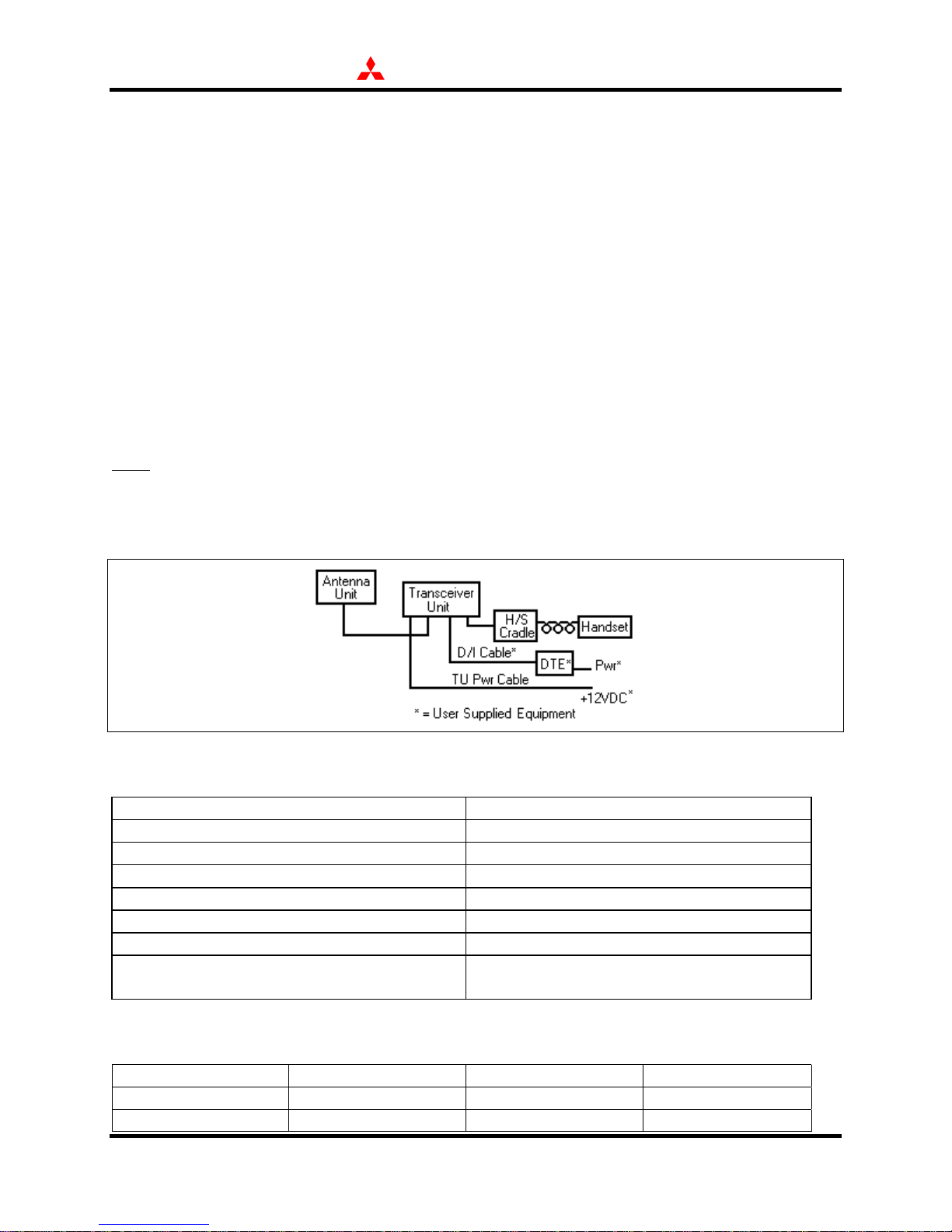
3. Connect the data interface (D/I) cable (provided b y customer) to the DTE port (TU) and the
COM port (DTE).
The following table lists key data port (TU) characteristics for reference:
Mechanical Interface DB-25 female
Electrical Interface RS-232
Communication mode Full duplex
Synchronization Start - Stop systems (Asynchronous)
Communication rate 1200bps, 2400bps, 4800 bps
Flow Control None
Error Correction Rate 1/2 convolutional coding
Functionality All “AT” commands listed in the Operating
Instructions
Every MT interfaces with one of the following character formats:
Start Bits Data Bits Parity Bits Stop Bits
1 7 even or odd 1
1 8 none 1
ST200 Series Technical Support Manual 25 January 2000
Page 29

MITSUBISHI ELECTRONICS AMERICA, INC.
Mitsubishi Electronics recommends the following DTE setup:
Communication rate 4800bps
Character format 8 bits, No parity, 1 stop bit
Flow Control None
1. Use a serial port (COMx), on the PC to MT connection for data transmission.
Note: The COM1 port is normally utilized for this connection.
2. The MT transmits all data transparently (RTS signal line is not used / CTS line always high)
so HW flow control is not necessary (i.e. ignored) but software flow control between end
equipment can be used (e.g. XON/XOFF).
3. When choosing a modem driver, select a basic Hayes compatible 4800bps modem as default,
or something as close to this as possible.
4. Various transfer protocols are supported; the standard configuration should be Zmodem.
5.8.6 Net Radio/Dispatch Operation
Net Radio or Satellite Dispatch capability is a special MT function that provides a half-duplex
digital network (or talk group) capability. This service requires the use of the Push-to-Talk
(PTT) Microphone (SZ300A), external speaker accessory, and a separate service subscription.
A customer can configure and re-configure up to 256 talk groups, or dispatch channels, with as
many as 10,000 MTs in all talk groups. Each MT can belong to 15 different talk groups. Talk
group configurations and attributes download from the ground segment every time an MT
powers on. The Net Radio service uses special protocols and messages on each of the previously
defined channels for downloading system parameters, setting up and tearing down networks, and
establishing communications between the speaker and all other members in a talk group.
Dealers should be able to provide end-users with more detailed information on Net Radio service
offerings.
5.9 Possible Cable Extensions
The following figure and table describe acceptable cable extensions for Mitsubishi MT
configurations. MT modifications should not include full lengths for Extension A and Extension
B. Note that adding any extension cable exposes the MT to various electromagnetic interference
conditions, therefore Mitsubishi Electronics does not guarantee audio performance.
ST200 Series Technical Support Manual 26 January 2000
Page 30

MITSUBISHI ELECTRONICS AMERICA, INC.
Extension Cable
Ref: Figure 1.
A
B
M\F means the cable has one male connector and one female connector, If the cables are not available, a standard
“gender bender” may be utilized.
Short Length \
Minimum Cable Type
50 ft \ ~15m
RS-232C Standard - M\F*
26AWG - <50pF\ft
Drain wire connects
connector housings for a
ground.
50ft \ ~15m
Flat Satin
RJ-45 M\F - 26AWG
Long Length \
Minimum Cable Type
100 ft \ ~30m
RS-232C Extended - M\F*
24AWG - <15pF\ft
Drain wire connects
connector housings for a
ground.
100ft \ ~30m
Category 3 LAN
RJ-45 M\F - 24AWG
5.10 Multiple Handsets
Mitsubishi MTs configured with both the basic handset and PTT handset can automatically
switch operations between regular voice and dispatch. One of the devices will always be in a
“sleep” mode, where the display does not remain in contact with the CTU. However, the
transceiver will automatically “wake up” the handset and route an incoming call when the MT is
idle. Users can manually wake up a sleeping handset with the press of any button (besides
power), for more than half a second. The SZ300A PTT Microphone Operating Instructions
manual provides a complete description of this “multi-terminal operation”.
5.11 Other Operational Considerations
♦ Fixed Site, ST221M, pointing requirements do not account for magnetic offset effects. This
phenomenon causes a difference between ma gnetic north and true north, which varies more
at high latitudes and over time.
♦ All configurations require a clear line of site to the satellite for reliable communications. The
L-Band MT signals must effectively propagate 22,300 miles / 36,000 km to the satellite
without significant distortion or attenuation. Mitsubishi MTs can communicate through most
glass (though some tinted or reflective glass coatings will attenuate the signal), plastics, and
ST200 Series Technical Support Manual 27 January 2000
Page 31

MITSUBISHI ELECTRONICS AMERICA, INC.
other non-metallic materials. Foliage can also potentially degrade signal quality. Users
should strive for a completely clear line-of-site for best performance.
♦ All terminals can preserve satellite connection despite signal (line of sight) blockages of up
to 15 seconds. Therefore, Mitsubishi MTs may not have to re-acquire the satellite or re-dial
the called party for temporary obstructions. For example, the ST211 land mobile
configuration can retain connections while driving under an overpass.
♦ The ST211 land mobile terminal requires roughly 10 seconds of static operation or motion
along a straight path at start-up, for rapid satellite acquisition and tracking. Turns and
maneuvers prior to acquisition skew the baseline BSU conditions, degrading performance.
♦ The RSSI, displayed on the handset, indicates received satellite signal strength on a numeric
scale of 0 through 80. The initial setup screen displays the RSSI and users can continuously
view signal strength using handset function 84. Mitsubishi MTs also display a graphic bar
representation of signal strength at all times, in the upper right hand corner of the handset
LCD. The table below shows the relationship between numeric and graphic RSSI values.
Numeric RSSI Graphic RSSI (Number of Signal Bars)
00
1-8 1
9-18 2
19-28 3
29-38 4
39-48 5
49-80 6
♦ The RSSI is a relative measure of received signal strength for a particular MT, based on
automatic gain control settings. RSSI values vary among MTs, even for the same received
signal strength. Dealers should not assume that a lower RSSI value for a particular MT,
compared with others, definitely indicates a problem (unless other problems are also present).
RSSI values in the 35-50 range are considered normal. It is unlikely that you will measure an
RSSI value of above 50 on your MT.
♦ The RSSI displays the received signal strength of the pilot channel during acquisition, the
GC-S channel after acquisition, and FES-C channel during and active call. The relative level
of these three channels differs with location, time, and network status.
♦ All MT configurations include a beam cross-over selection mode (function 96). Users can
select a threshold for the frequency with which their MT searches for another satellite beam
when a channel drops. These thresholds are very slow, slow, normal, and fast. Therefore,
users of the ST211 who typically travel across beam intersections would probably want to
select fast. In this case satellite acquisition times would improve for crossing between
satellite beams. Users who typically operate within a single satellite beam would probably
want to select very slow, resulting in a more efficient satellite acquisition. The ST221M has
the same feature within its software, but is not relevant since the unit will be installed in a
fixed location.
ST200 Series Technical Support Manual 28 January 2000
Page 32

MITSUBISHI ELECTRONICS AMERICA, INC.
♦ Background noise at either the MT end or the other user end may couple into the
communications link if at a high enough volume. Background noise may sound like garble
or be misconstrued as cross-talk or echo by the MT or PSTN end-users. Since the MT is
voice activated, this “garble” would only come through when the MT user is speaking.
♦ Signal propagation to and from the satellite inserts a noticeable delay into voice
communications. This delay is approximately 400 milliseconds from the time one party
speaks until the other party receives audio. For short question and answer type
communications the two-way delay is close to a one second, round trip from one speakers
perspective, without considering the time it takes a speaker to formulate their response.
Although this delay is noticeable, user expectations and discipline can easily overcome the
issue. Dealers should be familiar with this delay and help set customer expectations. The
propagation and processing delay should have little or no user impact on digital dispatch
(since it is half-duplex), data communications, or facsimile services.
♦ All Mitsubishi MTs are single channel communications devices. Users cannot switch
between handsets and data equipment while actively engaged in calls.
OmniQuest® Battery
• The length of standby time possible on the internal battery depends upon the specific
configuration settings of the MT for Backlight Mode Selection (FCN52) and Sleep Mode
(FCN 54). The general relationship of standby time to these settings is shown below (setting
Auto Power Off (FCN53) to Enable will also affect overall battery time):
SLEEP MODE (FCN 54) BACK LIGHT MO DE (FCN52) STANDBY TIME*
Enable OFF 8 hrs.
Enable 10 sec will vary
Enable ON 4 hrs.
Disable OFF 4.5 hrs.
Disable 10 sec will vary
Disable O N 3.5 hrs.
*
Using NiMH battery @25oC and beginning of battery life
• The optimal storage temperature of 25oC results in a discharge rate of roughly 60% per
month for the internal NiMH battery. Therefore, a battery which has been on the shelf for
one month should provide ~ 36 minutes of transmit time which would then degrade to ~ 22
minutes after two months of storage.
6.0 Installation
The installation of a Mitsubishi MT is simple, however, performing a correct installation is
extremely important.
Mitsubishi Electronics cannot offer rules or step-by-step procedures for every variation in site
conditions and customer requirements. However, MT configurations allow significant
ST200 Series Technical Support Manual 29 January 2000
Page 33

MITSUBISHI ELECTRONICS AMERICA, INC.
installation flexibility, allowing dealers to pay special attention to their safety and their
customers’ safety. Dealers should plan installations before their actual execution. Take into
account cable lengths, customer preferences, antenna placement and the potential use/access to
the system.
6.1 Fixed Site (ST221M)
There are no specific accessories to complete an ST221M installation. However, depending
upon the installation circumstances, items such as a pedestal to mount the MT handset cradle
may be required. These accessories are commonly available and manufactured by companies
other than Mitsubishi Electronics America, Inc.
The location of the antenna must be considered. The system should be tested by originating and
receiving actual calls after completing the installation. For the antenna, it is desirable to select a
high location with a large ground plane. The roof top of the site is particularly good. The
antenna may lose much of its gain if it is not mounted correctly. When installing the antenna, it
is necessary to consider the mechanical structure of and the physical location of the installation.
As mentioned previously, always check with the site owner to a gree on placement of th e system
components (Common Transceiver Unit (CTU), Handset (H/S), Antenna Unit (AU), etc.). Be
sure to inform the site owner if you intend to drill holes or apply permanent adhesives in or on
any of the cosmetic interiors or external surfaces of the site. Remind them that the holes will be
there if the system is removed from the site.
In order for the installer to avoid problems during and after installation, it is always
recommended to perform two basic steps before the actual installation begins: Site Pre-Check
and Installation Planning. Occupant and site safety should always be taken into consideration
when planning an installation.
6.1.1 Occupant and Site Safety
Occupant and site safety must be accorded absolute priority over all other consider ations when
installing a Mitsubishi MT. Objects installed on a site are to be placed in such a manner that
they will not cause injury to the site's occupants. These rules also require that the function of any
site safety system, for example, a ccess to fire extinguishers and their att achment hardware are
not to be impaired in any manner by installing the Mitsubishi fixed site satellite telephone at that
site.
Modern building sites contain a great deal of electronic equipment. Much of this electronic
equipment directly affects the operation of the site itself (network management computers,
heating/AC controllers). These electronic devices generate RF energy and are affected by
externally generated RF energy. Care must be taken to avoid detrimental interference with the
site’s other electronic equipment.
Site planners take great care to design their sites to minimize both radiated RF energy and reduce
the susceptibility of the site’s electronics systems to external RF energy. However, if the
ST200 Series Technical Support Manual 30 January 2000
Page 34

MITSUBISHI ELECTRONICS AMERICA, INC.
operational integrity of the site is to be preserved, basic guidelines must be observed when
installing the MT at a site. For example, site planners often issue guidelines and precautions that
are specific to a particular site, and these must be observed.
Basic Rules:
1. No portion of any antenna, Radio Frequency Unit (RFU), or Transceiver Unit (TU)
should be placed within 12" of any computer or controller module, sensor or other
existing electronic device in the site.
2. Wires or cabling for the MT should be routed as far from existing site cabling as possible,
and in no event should they be placed next to or be routed in parallel with the cabling for
any site system.
3. Whenever a cable is routed through/over a metallic object, the cable must be protected
against damage with a protective sleeve.
4. Any connection to the existing site electrical system must be done in accordance with the
customer, and only using site approved components.
5. All connections to the site's power distribution system must be fused.
6. After the installation has been completed, but before the site is released to the customer,
the installer must verify that the functioning of the site’s systems has not been affected by
the MT installation.
Performing a “pre-check” of the customer's site before the installation will identify any preexisting problems with the site. Customers are not always aware of the functional state of all
parts of their site, and it is very easy for the custom er to blame th e inst aller for (as an ex ample) a
malfunctioning alarm control system, if the site has not been checked out before the installation
has started.
The final installation should be presented in detail to the customer. This should help eliminate
any controversy with the customer about instruments, lights and/or systems that do not operate
correctly when the installation has been completed.
6.1.2 General Installation Standards
The following list of standards will help ensure that the equipment operates properly over a long
period of time. The extra attention and care that is given initially may save time and effort in the
future.
1. The National Electrical Code requires lightning protection for cabling between the
fixed site antenna and supporting structure (e.g. building roof). However, specific
electromagnetic pulse protection requirements vary by customer and site. The
professional doing the fixed site installation should determine these requirements with
the customer and install equipment based on a variety of open industry standards.
2. Wherever possible, route the terminal cables and the power cable together. This
makes it easier to service the s ystem. If one or more of the accessories are installed,
route the associated cable with the other cable if possible.
ST200 Series Technical Support Manual 31 January 2000
Page 35

MITSUBISHI ELECTRONICS AMERICA, INC.
3. Because of the type of cables that are used, it is recommended that the power cable
should be routed from the transceiver unit installation location to the site power plant.
Likewise, it is recommended that the cable which connects the user interface (handset
cradle) should be routed from the site mounting location to the transceiver unit.
4. Cable lengths are fixed and must not be spliced to add or remove length.
5. Grommets should be used whenever routing cable through holes drilled in metal or
through bulkheads. A ribbed flexible wiring loom may also be used to protect cables
in hazardous locations where damage may occur.
6. In addition to grommets, silicone sealant (RTV) should be used to weatherproof all
holes that are drilled on the outside of the site.
7. All cables should be securely fastened with cable ties to fixed objects so that they do
not dislodge or flap loosely. Cables should be secured every 12-18 inches (30-45cm).
8. Ultra-violet resistant cable ties should be used when securing cables outside of the
site. Other types of cable ties do not withstand the weather conditions or exposure to
sunlight.
9. The main power or constant 120V AC line should be unswitched and connected
directly to the site AC power supply. The built-in fuses in the power supply provide
adequate current protection for the MT electrical system.
10. Placement of the CTU must be in an environmentally protected and ventilated area.
11. The electronic components are not waterproof. They are only weather resistive to
dust or naturally occurring humid conditions (normal weather). Excessive high
humidity conditions or extreme temperature changes are not considered “normal”.
The fixed site antenna unit is considered weatherproof.
12. The wiring to the AU should never be in a downward route. A “drip loop” should
always precede the connection to the AU. This retards the natural “wicking” action
of moisture into the AU.
6.1.3 Installation Planning
Proper location of the various components of the MT is one of the most important parts of the
installation. It has a direct effect on the customer's ease of use of the MT. The Installation
engineer or technician should plan after consultation with the customer.
The following illustration is a complete overview of all the components and available (optional)
accessories for the Mitsubishi Fixed Site Satellite Terminals.
ST200 Series Technical Support Manual 32 January 2000
Page 36

AU601B
Fixed Site
Antenna Unit
MITSUBISHI ELECTRONICS AMERICA, INC.
SZ300A
PTT
SZ100A
Handset
SZ130A
Handset
Cradle - 3
Microphone
(Optional)
FZ-806A
Hands-Free
Microphone
(Optional)
FSC50
Fixed Site Cable Kit
2 RF Cables
1 Data Cable
Junction
Box
TU200A
Common
Transceiver
Unit
FZ-1283A
Monitoring
Speaker
(Optional)
PUP55-13-J9
Power Supply
17600
Power Cord
As with any electronic product, it is good practice to formulate a standard pattern to perform the
actual installation. Therefore, Mitsubishi Electronics America recommends installing the
equipment in the following order, but the installer should use his best judgment based on the
particular case:
1. Antenna Unit (AU).
2. Transceiver Unit (TU).
3. Junction-box and Cradle.
4. Plug in user interface (Handset, PTT Microphone).
5. Accessories (Hands Free Microphone, Monitoring Speaker).
6. MT Power Supply.
7. Other Cables (for external equipment or extensions etc.).
ST200 Series Technical Support Manual 33 January 2000
Page 37

MITSUBISHI ELECTRONICS AMERICA, INC.
Note: Always remember personal safety practices. Use common sense. Use safety goggles and
hearing protection to protect against damage to your eyes and ears.
6.1.4 Antenna Unit
To ensure the best communications channel, the antenna must have a clear lin e-of-sight to the
network satellite.
The Mitsubishi Limited Warranty covers installations that use fixtures other than those
Mitsubishi supplies, as long as their structural integrity meets or exceeds our specifications.
However, if damage results from substandard installation methods or components, the Mitsubishi
Limited Warranty does not apply to any necessary repairs.
Please consider the following three points during AU installation:
♦ Leveling
The AU must be level with respect with the horizon when installed. This ensures the best
possible operation regardless of the orientation of the site.
♦ Torque specifications
Do not over-torque the bolts used to mount the AU. Loctite should be applied to the
threads of the bolts prior to installing them. The torque specifications for these bolts is
24 in./lb. Do not use air impact tools to tighten these bolts.
♦ Painting
Never paint the AU. Paint will degrade the signal strength and the solvent in the paint
will damage the Radome.
To determine the proper elevation (vertical) angle and azimuth (horizontal angle) to point the
antenna:
1. Locate your approximate position on the following antenna pointing map
ST200 Series Technical Support Manual 34 January 2000
Page 38

MITSUBISHI ELECTRONICS AMERICA, INC.
2. From that position, determine the approximate elevation (El) angle and azimuth (Az)
angle within 5 degrees.
3.
Adjust the Az angle of the antenna unit to the azimuth that you determined in Step 2,
using a compass if necessary
4. Adjust the El angle of the antenna unit to the angle that you determined in Step 2, by
using the scale provided on the antenna unit mounting bracket.
.
6.1.5 Transceiver
The CTU may be installed in several locations (i.e. under the package tray, against a wall or
bulkhead, etc.) using the mounting brackets and hardware included with the CTU.
Installations may be performed with fixtures not supplied by Mitsubishi. Keep in mind that if
the structural integrity of the non-supplied mounting fixtures meets or exceeds the supplied
installation fixtures, these installation methods are not violations of the Mitsubishi Limited
Warranty. However, if substandard installation methods are us ed and subsequ ent dama ge results
due to the installation method, the Mitsubishi Limited Warranty does not apply to the repair of
that damage.
Take care to observe the connector types and their assignments, since some cable connectors can
be inserted into the wrong connector ports. Damage due to accidental connection of incorrect
cables to transceiver ports is not covered by the Mitsubishi Limited Warranty.
The following items are important for a successful CTU installation.
ST200 Series Technical Support Manual 35 January 2000
Page 39

MITSUBISHI ELECTRONICS AMERICA, INC.
♦ Leveling
The CTU must be level when installed.
♦ Location
No other items should be placed on top of the CTU or cables. Make sure that the CTU is
not exposed to rain or other sources of moisture. The installation surface must have
sufficient strength. If the location selected is not strong enough, an alternate location
must be selected or an appropriate surface must be constructed. The installation area
must not be easily vibrated or exposed to impact. The CTU should be installed so that it
is out of the way and protected, but it should also be in a location that is accessible for
servicing. Avoid installing the CTU near the area where heat is generated or where the
CTU may be artificially heated to a high temperature.
There should be a minimum of two inches of air space surrounding the CTU to provide adequate
convection cooling. This means that when installed, the CTU should not be in an area wh ere
items (rags, carpet, paper or accid entally placed obje cts) ma y cover the CTU, and woul d contain
the heat generated by the CTU.
♦ Torque Specifications
The bolts used to mount the CTU should not be over-torqued. The torque specifications
for these bolts is 24 in./lb. Do not use air impact tools for tightening these bolts.
♦ Cables and Connectors
The CTU should be positioned in the site so that the connectors from the AU, handsets
and DTE, and power cables are protected. Make provisions to allow at least two inches
of straight cable available at the connection point(s) of the CTU.
Be sure to route cables where they won't get pinched or stepped on, and where they will not
make any sharp turns. If possible, the power cable should be run with the other site power
connections. Any excessive cabling should be secured to a fixed object in the site with cable
ties, or stowed out of sight. Use grommets for routing cable through holes drilled in metal or
through bulkheads. Use silicone sealant (RTV) to weatherproof all holes that are drilled in the
site.
CTU Installation Steps
Required tools: #2 Phillips screwdriver and drill (3.6mm).
a. Install “Angle Bracket-A” to both sides of the CTU. Find a level and stable area in
the site. Mark the installation surface at the position of the four oval holes on the
lower side of “Angle Bracket-A”. Make sure that the installed CTU does not interfere
or make it difficult to perform standard operation procedures.
b. Use the drill to make holes 3.6 mm in diameter at the marked positions on the floor.
ST200 Series Technical Support Manual 36 January 2000
Page 40

MITSUBISHI ELECTRONICS AMERICA, INC.
c. Connect the interface cable to the CTU, and use standard screws (M5x20 self-tapping
screws) to secure the CTU. Secure the interface cables so that they can not be
damaged from normal day-to-day operation (securing materials are not included).
6.1.6 Power Connection
The ST221M fixed site MT includes the PUP-55-13-J9 power supply. The diagrams below
explain the power connections for the CTU and the power supply.
Terminal PortDTE Port
BSU
Conn.
Antenna Unit
Connection
Power Connector
CTU Power Connector
Pin 1 Ground
1 2
Pin 2 +12V (Input to CTU)
Pin 3 Horn Relay (Output from CTU)
43
Pin 4 Ignition Sense (Input to CTU)
ST200 Series Technical Support Manual 37 January 2000
Page 41

MITSUBISHI ELECTRONICS AMERICA, INC.
PUP-55-13-J9
2 1
34
6.1.7 Cable Runs
The standard antenna to transceiver cable length is 50 ft for the ST221M terminal.
♦ Cable routing
Ensure that cables are not stressed (stretched) and are not pulled or pinched. When
routing the AU-cable avoid tight turns and possible rubbing of the cable. It is strongly
recommended that the maximum turn radius of the AU cable be limited to 2 inches (5
cm) in the horizontal (sideways) and vertical (up and down) direction. Form a drip loop
before the AU to prevent “wicking” of water into the AU housing.
♦ Cable connecting
Make sure the red and blue coax cables at the AU end are connected to the red and blue
coax connectors the CTU end respectivel y. Do not cross the colors. Connect the control
(data) cable to the AU and the CTU.
T
E
R
M
A
D
U
T
E
P
S
U
Secure the cables every 12-18 inches (30-45 cm) along the cable run. Be sure that no weight is
placed on the AU cables. Form a drip loop at the AU to prevent “wickin g” of water into the AU
housing. Apply fusion tape or cold shrink to all exposed connections to provide
weatherproofing.
ST200 Series Technical Support Manual 38 January 2000
Page 42

MITSUBISHI ELECTRONICS AMERICA, INC.
6.1.8 Junction Box
The junction box is the interface for the Hands Free Microphone (FZ-806A), Monitoring Speaker
(FZ-1283A) and Push to Talk (PTT) Microphone (SZ300A) accessories. Installation requires
three steps:
1. Select a concealed place near the MT operator. Install the j unction box in place with the
included hook plate. The hook plate can be fastened to the site with either a screw or
double-sided installation tape.
2. When you fasten the hook plate with adhesive tape, pre-treat the place where the
adhesive tape will be applied using a cloth containing a synthetic detergent or alcohol.
Remove oil, water (moisture), stains, and so on.
Route the remote cable through the site and secure occasionally with tie straps to prevent
3.
movement of the cable. The cable should be routed in areas where no damage will occu r
to the cable. Once the cable is rout ed, connect the other end of the remote cable to the
CTU.
ST200 Series Technical Support Manual 39 January 2000
Page 43

6.1.9 Handsets and Accessories
MITSUBISHI ELECTRONICS AMERICA, INC.
The following four steps and subsequent figure are for handset cradle installation:
1. Select the mounting position for the Handset cradle so that it will be within easy reach of
the user and does not disturb day-to-day operations.
2. Install the Handset cradle with the attachment screws by using a mounting stand (a
mounting stand is not included in the kit). This is the same type mounting stand which is
commonly used for cellular phone installations.
3. Route the remote cable and secure occasionally with tie straps to prevent movement of
the cable. The cable should be routed in areas where regular usage/operation will not
damage the cable. Once the cable is routed, connect the other end of the remote cabl e to
the CTU or other mounting location.
Note: The handset cradle type SZ130A includes a junction box for hands free and dispatch
operation using the PTT Microphone (SZ300A).
ST200 Series Technical Support Manual 40 January 2000
Page 44

MITSUBISHI ELECTRONICS AMERICA, INC.
The Push To Talk (PTT) Microphone (SZ300A) is for dispatch/net radio use.
1. Select the mounting position for the PTT Microphone at the operating area, so that it will
be within easy reach of the user.
2. Install the PTT Microphone in place with the hook attached. The hook can be fastened in
the site with the included screws.
3. Plug the cable into the port indicated "PTT-MIC" in the junction box.
To install the monitoring speaker, select a mounting position in a convenient location inside the
site so that it will not disturb day-to-day operations. Install the monitoring speaker with attached
screws and speed nuts. Plug the cable into the port indicated "EXT-SP" in the junction box.
Note: Hands free operation performs best when the microphone is as close as possible to the
user's voice and the monitoring speaker is reasonably far from the hands-free microphone.
ST200 Series Technical Support Manual 41 January 2000
Page 45

MITSUBISHI ELECTRONICS AMERICA, INC.
Hands-free micropho ne installation is as simple as plugging the microphone cable into the port
indicated “EXT-MIC” in the junction box.
6.2 Land Mobile (ST211)
There are no specific accessories required to complete an installation. However, depending upon
the installation circumstances, items such as a pedestal to mount the MT handset cr adle or hand
held cellular phone cradle may be required. These accessories are commonly available and
manufactured by companies other than Mitsubishi Electronics America, Inc.
The location of the antenna must be considered. The system should be tested by originating and
receiving actual calls after completing the installation. For the antenna, it is desirable to select a
high location with a large ground plane. The roof top of the vehicle is particularly good. When
installing the antenna, it is necessary to consider the mechanical structure of and the physical
location of the installation.
As mentioned previously, always check with the vehicle owner to agree on placement of the
system components (Common Transceiver (CTU), Handset (H/S), Antenna (AU), etc.). Be sure
to inform the vehicle owner if you intend to drill holes or apply permanent adhesives in or on any
of the cosmetic interior or external surfaces of the vehicle. Remind them that the holes will be
there if the system is removed from the vehicle.
In order for the installer to avoid problems during and after installation, it is always
recommended to perform two basic steps before the actual installation begins: Vehicle PreCheck and Installation Planning. Occupant and vehicle safety should always be taken into
consideration when planning an installation.
6.2.1 Occupant and Vehicle Safety
ST200 Series Technical Support Manual 42 January 2000
Page 46

MITSUBISHI ELECTRONICS AMERICA, INC.
Occupant and vehicle safety must be accorded absolute priority over all other considerations
when installing the Mitsubishi MT. The Federal Motor Vehicle Safety Standards require that
objects installed in a vehicle be placed in such a manner that they will not cause injury to the
vehicle's occupants if the vehicle is involved in a accident. These rules also require that the
function of any vehicle safety system, for example, the seat belts and their atta chment hardware,
not be impaired in any manner by any device installed in the vehicle.
Unlike older vehicles, modern vehicl es contain a great deal of electronic equipment. Much of
this electronic equipment direct ly affects the operation of th e vehicle itself (engine management
computers, heating/AC controllers), vehicle safety systems (air bag impact sensors and inflation
controllers) or both (anti-lock brake system or traction control system computers). These
electronic devices generate RF energy and are affected by externally generated RF energy.
Vehicle manufacturers take great care to design their vehicles and systems to minimize both
radiated RF energy and reduce the susceptibility of the vehicle’s electronics systems to external
RF energy. However, if the operational integrity of the vehicle is to be preserved, the following
basic guidelines must be observed when installing the MT system (or any device that generates
RF energy) in a vehicle. Vehicle manufactures h ave issued guidelines and precautions that are
specific to a their particular make and/or model of vehicle which must be observed. Information
regarding vehicle-specific guidelines can be obtained from the vehicle manufacturer 's Technical
Assistance Department.
Basic Rules:
1. No portion of the MT should be mounted within 6 inches (15 cm) of any computer or
controller module, sensor or other existing electronic device.
2. No portion of any transmitting antenna, its integrated Radio Frequency Unit (RFU) or
Transceiver should be placed within 12" (30 cm) of any computer or controlle r module,
sensor or other existing electronic device in the vehicle.
3. Wires or cabling for the subscriber unit should be routed as far from existing vehicle
cabling as possible, and in no event should they be placed next to or be routed in parallel
with the cabling for any vehicle system.
4. Whenever a cable is routed either through or over a metallic object, the cable must be
protected against damage with an insulating medium.
5. Any connection to the existing vehicle electrical system must be done in a manner, and
using components, approved by the vehicle manufacturer.
6. All connections to the vehicle's power distribution system must be fused.
7. After the installation has been completed, but before the vehicle is released to the
customer, the installer must verify that the functioning of all vehicle systems has been
unaffected by the subscriber unit installation.
8. If an MT is interfering with the functioning of ANY vehicle system it must be disabled
until the interference problem is resolved.
Performing a “pre-check” of the customer's vehicle before the installation will identify any preexisting problems with the vehicle. Customers are not always aware of th e functi onal state of all
parts of their vehicle, and it is very easy for the customer to blame the installer for (as an
example) a malfunctioning cruise control system, if the vehicle has not been checked out before
the installation has started.
ST200 Series Technical Support Manual 43 January 2000
Page 47

MITSUBISHI ELECTRONICS AMERICA, INC.
Once the installation is completed, the customer should be given a detailed overview and any
pre-existing conditions should be identified, as this will help eliminate future controversies
regarding existing problems with the vehicle.
While making your “pre-check” inspection, make note of any special features or accessories such
as anti-lock braking systems, air bags, sound systems, alarms, information computers or other
electronic systems on the vehicle—these types of devices demand special installation
precautions. As the final part of the vehicle pre-check, ask the customer to remove any valuables
such as money, briefcases and such from the vehicle. This will help eliminate potential
controversies and will make the customer confident that they are dealing with people of integrity.
6.2.2 General Installation Standards
The following list of standards that will help ensure that the equipment operates properly. The
extra attention and care that is given initially may save time and energy down the road.
1. Wherever possible, route the terminal c ables and power cable together. Thi s makes it easier
to service the system. If one or more of the accessories are installed, route the associated
cable with the other cable if possible (i. e., cellular antenna).
2. Because of the type of cables that are used, it is recommended that the power cable should be
routed from the transceiver unit installation location to the dashboard and engine
compartment (from the back of the vehicle to the front). Likewise, it is recommended that
the cable which connects the user interface (handset cradle) should be routed f rom the inside
of the vehicle mounting location to the transceiver unit (from the front of the vehicle to the
back).
3. Cable lengths are fixed and must not be cut to add length or remove excess. The only
exception is the power cable. It may be shortened or lengthened. However, whenever
lengthening the power cable, always use the same or better gauge of wire. Always re-attach
the in-line fuse holders and install the fuses provided.
4. Whenever routing cable through holes drilled in metal or through bulkheads, use grommets.
Ribbed flexible wiring loom may also be used to protect cables in hazardous locations where
damage to those cables may occur. In addition to grommets, use silicone sealant (RTV) to
weatherproof all holes drilled on the outside of the vehicle.
5. All cables should be securely fastened with cable ties to fixed objects so that they do not
dislodge or flap loosely when the vehicle is in motion. Cables should be secured every 12-18
inches (30-45cm).
6. Ultra-violet resistant cable ties should be used when securing cables outside of the vehicl e.
Other types of cable ties do not withstand the weather conditions or exposure to sunlight.
7. The main power or constant +12V line (red) should be un-switched and connected directly to
the vehicle battery. This line must not be connected to the switched accessory bus or an y
other switched line. Also, this line should never be connected to the vehicle fuse box or
other fused sources. The built-in fuses in the cables provide adequate current protection for
the system and for the vehicle electrical system.
ST200 Series Technical Support Manual 44 January 2000
Page 48

MITSUBISHI ELECTRONICS AMERICA, INC.
8. The ground (black) line should be connected directly to the vehicles’ battery ground.
9. The switched ignition line should be connected to a +12 V switched (accessory) line. Be
careful not to connect this line t o an accessory line that may carry a low vol tage accessory
trigger voltage. In many vehicles a low voltage trigger line may be used. This line carries
less than the required +12 Volts. When checking for the switched +12V line, do not rely on
a “test light”. Confirm your circuit choice with a voltmeter.
10. Placement of the CTU must be in a protected but ventilated area. There are no specific areas
to install the CTU, however it is possible to locate the CTU under the seat, on the rear cab
wall of a typical truck or four wheel drive or in the trunk compartment of a typical
automobile.
11. The electronic components are not waterproof. They are only weather resistant to dust or
naturally occurring humid conditions (normal weather). Ex cessive hi gh humidity conditions
or extreme temperature changes are not considered “normal”.
12. Wiring to MT components should not be run in an unbroken downward route. A “drip loop”
should always precede the connection to the AU. This retards the natural “wicking” action of
moisture into the AU. The Dome and Transportation Antennas are “weather-proof”.
6.2.3 Installation Planning
Proper location of the various components of the MT is one of the most important parts of the
installation. It has a direct effect on the customer's ease of use of the MT. Installation should be
planned by the installation staff after consultation with the customer. Safety, technical feasibility
and customer desires should always be taken into consideration when planning an installation.
The following figure is an overview of the components and available (optional) accesso ries for
the Mitsubishi ST211 land mobile terminal.
ST200 Series Technical Support Manual 45 January 2000
Page 49

SZ100A
Handset
MITSUBISHI ELECTRONICS AMERICA, INC.
SZ300A
PTT
Microphone
(Optional)
SZ130A
Handset
Cradle - 3
FZ-806A
Hands-Free
Microphone
(Optional)
AU201A
Dome
Antenna Unit
TU200A
Common
Transceiver
Unit
AU1200A (S)
Beam Steering
Unit
Junction
Box
SZ460A
Power Cable
FZ-1283A
Monitoring
Speaker
(Optional)
SZ604A
Cigarette Lighter
Adapter
(Optional)
Before proceeding with the installation, please make sure that all items listed on the packing slip
have been received and verify that the list matches your purchase order. The following bill of
materials for the ST211 should help identify if any component is missing. If any item is missing,
please contact your distributor immediately.
(1) Dome Antenna Unit (AU201A) Including:
(1) 18 foot (5.7 m) Cable with 3 Connectors
(1) 1 foot AU-TU Cable to connect the AU cable to the single CTU connector
(1) Beam Steering Unit (AU1200A(S)) Including:
(1) Mounting Plate
(4) Screws
(1) Common Transceiver Unit (TU200A) Including:
(2) Installation Brackets
(4) Tapping Screws
(4) Pan Screws
(1) Handset (SZ100A) Including:
(1) Coil Cord
(1) Handset Cradle-3 (SZ130A) Including:
ST200 Series Technical Support Manual 46 January 2000
Page 50

MITSUBISHI ELECTRONICS AMERICA, INC.
(1) CTU Cable
(1) Junction Box
(1) Clip w/Screw
(4) Screws
(1) Power Cable (SZ460A) Including:
(3) Fuses
(1) ST200 Series Operating Manual (ST200N02)
Just as with any other 12 Volt vehicle product (i.e., car stereo, cellular phone, etc.), it is a good
practice to formulate a standard pattern to perform the actual installation. Mitsubishi Electronics
recommends the following order:
1. Dome Antenna Unit (AU)
2. CTU Power Cable
3. User Interface Cradle and Cables
4. Plug in Handset and/or PTT Microphone
5. Common Transceiver Unit (CTU)
6. Beam Steering Unit (BSU)
7. Accessories (Hands Free Microphone, Monitoring Speaker)
8. Other Cables (for accessories, etc.)
Although this is a recommended installation plan, the installer must use their best judgment
in planning the installation.
Note: Always remember personal safety practices. Use common sense. Use safety goggles and
hearing protection to protect against damage to your eyes and ears.
The following two figures show typical land mobile MT component locations—however,
installations will vary.
ST200 Series Technical Support Manual 47 January 2000
Page 51

MITSUBISHI ELECTRONICS AMERICA, INC.
Handset
Handset
The figure below identifies key fixed cable lengths. Attempts to modify these cable lengths will
affect MT performance and void the limited warranty.
SZ130A
Handset
Cradle
SZ300A
Push to Talk
Microphone
FZ-806A
Hands Free
Microphone
FZ-1283A
Monitoring
Speaker
AU201A
Mid-Gain
Dome
Cable Length
34.4 inches
Cable Length
60 inches
Cable Length
177 inches
Cable Length
177 inches
Cable Length
216 inches
Junction
Box (Part
of SZ130A)
RJ-45
On Junction
Box
Mini-Plug
On Junction
Box
Sub Mini-Plug
On Junction
Box
AU
Terminal
Port
Cable Length
197 inches
AU
Terminal
Port
ST200 Series Technical Support Manual 48 January 2000
Page 52

MITSUBISHI ELECTRONICS AMERICA, INC.
6.2.4 Dome Antenna Unit
The dome AU should be mounted on the roof in the center of the vehicle, as these instructions
indicate. Please keep in mind the following four rules of thumb.
♦ Leveling
The AU must be level when installed. This ensures the best possible operation
regardless of the orientation of the vehicle.
♦ Torque specifications
The bolts used to mount the AU should not be over-torqued. Loctite should be
applied to the threads of the bolts prior to installing them. The torque specifications
for these bolts is 24 in./lb. (not ft./lb.). Do not use air impact tools to tighten these
bolts.
♦ Painting
Never paint the AU, since it will degrade the signal strength and the solvent in the
paint will damage the Antenna Radome.
♦ Cable routing
Ensure that cables are not stressed (stretched) and will not pull or pinch when the
trunk lid is opened and closed. When routing the AU-cable avoid tight turns and
possible rubbing of the cable. It is strongly recommended that the maximum turn
radius of the AU cable be limited to 2 inches (~5cm) in a horizontal (sideways) and
one (1) inch (~3cm) bend in the vertical (up and down) direction. The recommended
way to route the AU-cable is up the inside bulkhead of the trunk (where the CTU is
installed) and to the outside of the vehicle, over the center of the rear window (from
the trunk) to the roof. Install the AU-cable by using the cable guide.
The figure below illustrates the direct mount approach, with four M5 screws attaching the AU
directly to vehicle roof.
ST200 Series Technical Support Manual 49 January 2000
Page 53

MITSUBISHI ELECTRONICS AMERICA, INC.
A typical direct roof installation, below, requires a hole large enough (approximately 3/4”[2cm])
to pass the AU connector into the vehicle. A perforated (solid with a slit) grommet and silicon
(RTV) sealant should be used where the cable penetrates the vehicle. Silicon (RTV) sealant
should also be used around the bottom of the AU and injected into each screw hole to
weatherproof the vehicle.
Mitsubishi Electronics strongly recommends a maximum AU cable turn radius of two (2) inches
(5 cm) in a horizontal (sideways) and one inch bend in the ve rtical (up and down) direction. The
typical AU-cable routing is down by the inside bulkhead of the trunk, where the CTU is
installed.
6.2.5 Transceiver
Take time to observe the connector types and their assignments (see section 6.2.6). Some cable
connectors may be capable of being inserted into the wrong connector port. Damage due to
accidental connection of incorrect cables to transceiver ports is not covered by the Mitsubishi
Limited Warranty.
ST200 Series Technical Support Manual 50 January 2000
Page 54

MITSUBISHI ELECTRONICS AMERICA, INC.
Terminal PortDTE Port
BSU
Conn.
Antenna Unit
Connection
Power Connector
The following figure shows a typical placement of the CTU, but other locations like under the
package tray and against the rear seat bulkhead are acceptable. The CTU placement must be out
of the way and protected from loose items that may fall on top of the unit or bump the
connections.
Installations may be performed with fixtures not supplied by Mitsubishi. Keep in mind that if
the structural integrity of the non-supplied mounting fixtures meet or exceed the supplied
installation fixtures, these installation methods are not violations of the Mitsubishi Limited
Warranty. However, if substandard installation methods are us ed and subsequ ent dama ge results
due to the substandard installation method, the Mitsubishi Limited Warranty does not apply to
the repair of that damage.
The following items are important CTU installation considerations:
♦ Leveling
The CTU must be level when installed, especially when the BSU is connected. You
cannot level the BSU alone with the standard BSU mount. The "!"on th e BSU must
point upward.
♦ Protected Area
ST200 Series Technical Support Manual 51 January 2000
Page 55

MITSUBISHI ELECTRONICS AMERICA, INC.
The CTU should be installed so that the spare tire, tire jack, tools, tire chains or other
items are not thrown on top of the CTU or cables. Make sure that the CTU cannot be
exposed to rain or other sources of moisture. Do not put anything on top of the CTU
(e.g., luggage, etc.). The installation surface must have sufficient strength. If the
location selected is not strong, an alternate location must be selected o r an appropriate
surface must be constructed. The installation area must not be easily vibrated or
exposed to impact while the car is in motion.
♦ Accessibility
The CTU should be installed so that it is out of the way and protected, but it should
also be in a location that is accessible for servicing.
♦ Heat
Avoid installing the CTU near the area where heat is generated or where the CTU
may be artificially heated to a high temperature.
♦ Sufficient Air Space
There should be a minimum of two inches of air space surrounding the CTU to
provide adequate convection cooling. This means that when installed, the CTU
should not be in an area where items (rags, carpet, paper or accidentally placed
objects) would contain the naturally generated heat of the CTU.
♦ Torque specifications
The bolts used to mount the CTU should not be over-torqued. The torque
specifications for these bolts is 24 in./lb. (not ft./lb.). Do not use air impact tools for
tightening these bolts.
♦ Protect cable and connectors.
The CTU should be positioned in the vehicle so that the connectors from the AU,
BSU, user interface, and power are protected. Make provisions to allow at le ast two
(2) inches (5 cm) of straight cable available at the connection point(s) of the CTU.
♦ Cable Routing
Be sure to route cables where they won't get pinched or stepped on. Do not make any
sharp turns or route the cable near the br ake, clutch, and accelerator. If possible, the
power cable should be run under the carpeting. Any excessive cabling should be
secured to a fixed object in the trunk with cable ties, or stowed out of sight behind
panels. Grommets should be used whenever routing cable through holes drilled in
metal or through bulkheads and silicone sealant (RTV) should be used to
weatherproof all holes that are drilled in the vehicle.
ST200 Series Technical Support Manual 52 January 2000
Page 56

MITSUBISHI ELECTRONICS AMERICA, INC.
Standard Horizontal CTU Installation Steps
Required tools: Phillips (No. 2) screwdriver and drill (3.6mm).
Use standard or specified hardware and install securely. Do not damage the fuel tank or vehicle
cables when drilling the holes through the trunk floor.
a) Install “Angle Bracket-A” to both sides of the CTU. Find a level and stable area in
the trunk. Mark the trunk floor at the position of the four oval holes on the lower side
of “Angle Bracket-A”. Make sure that the installed CTU does not interfere or make it
difficult to take out or put back the spare tire or tools.
b) Use the drill to make holes 3.6mm in diameter at the marked positions on the floor.
Carefully check the vehicle to make sure that you do not damage systems or items
under the floor (e.g., gas tank, exhaust pipe, catalytic converter, vehicle wiring, etc.)
c) Secure the BSU. Connect the interface cable to the CTU, and use standard screws
(M5x20 self-tapping screws) to secure the CTU. Secur e the interface cable so that it
can not be damaged when loading/unloading the trunk (securing materials are not
included).
ST200 Series Technical Support Manual 53 January 2000
Page 57

MITSUBISHI ELECTRONICS AMERICA, INC.
6.2.6 Power Connection
There are two methods for powering the CTU in a land mobile MT: the power cable that is
included with the MT or the optional cigarette lighter adapter (CLA). The diagrams below show
the CTU power connection and the SZ406A power cable and the SZ604A CLA.
TU200A Common Transceiver Unit Power Connector
Terminal PortDTE Port
BSU
Conn.
Antenna Unit
Connection
Power Connector
CTU Power Connector
Pin 1 Ground
1 2
Pin 2 +12V (Input to CTU)
Pin 3 Horn Relay (Output from CTU)
Pin 4 Ignition Sense (Input to CTU)
SZ406A Power Cable and SZ604A Cigarette Lighter Adapter
43
Red +12V
Green Horn Alert
Black Ground
White Ignition Sense
+12V
Ground
SZ604A
ST200 Series Technical Support Manual 54 January 2000
Fuse
Fuse
Fuse
2 1
34
Page 58

MITSUBISHI ELECTRONICS AMERICA, INC.
Always disconnect the negative (-) side of the battery prior to any electrical work on a vehicle.
Even if the installer has disconnected the battery, the vehicle is not totally immune to slips.
Some vehicle systems retain power for some time after the battery has been disconnected.
Shorting or grounding the wrong wire or connector could activate the air bag, for example,
necessitating a costly and needless repair.
6.2.7 Junction Box
The junction box is the connection interface for the Hands Free Microphone (FZ-806A),
Monitoring Speaker (FZ-1283A) and Push to Talk (PTT) Handset (SZ300A) accessories. Refer
to figure in Section 6.1.8.
1. Select a concealed place under the front seat or under the d ashboard. Install the junction box
in place with the included hook plate. The hook plate can be fastened to the vehicle with
either a screw or double-sided installation tape.
2. When you fasten the hook plate with adhesive tape, pre-treat the place where the adhesive
tape will be applied using a cloth containing a synthetic detergent or alcohol. Remove oil,
water (moisture), stains, and so on.
3. Route the remote cable under the vehicle carpet and secure occasionally with duct tape to
prevent movement of the cable. The cable should not be routed in are as where the action of
seat adjustment could damage the cable. Once the cable is routed, connect the other end of
the remote cable to the CTU in the trunk
6.2.8 Handsets and Accessories
Handset Cradle (refer to figures in section 6.1.9)
1. Select the mounting position for the Handset cradle so that it will be within easy reach of the
user and not disturb driving.
2. Install the Handset cradle with the attachment screws by using a mounting stand (a mounting
stand is not included in the kit). This is the same type mounting stand commonly used for
cellular phone installation.
3. Route the remote cable under the vehicle carpet and secure o ccasionally with tap e to prevent
movement of the cable. The cable should not be routed in areas where the action of seat
adjustment could damage the cable. Once the cable is routed, connect the other end of the
remote cable to the CTU.
The Push To Talk (PTT) Microphone (SZ300A) is for dispatch radio use
1. Select the mounting position for the PTT Microphone on the dash board or the front console,
so that it will be within easy reach of the user and not disturb driving.
ST200 Series Technical Support Manual 55 January 2000
Page 59

MITSUBISHI ELECTRONICS AMERICA, INC.
2. Install the PTT Microphone in place with the hook attached. The hook can be fastened to the
vehicle with the attached screws.
3. Plug the cable into the port labeled "PTT-MIC" in the junction box.
In the illustration above, the user interface terminal cable does not exit the trunk. NEVER route
cables outside the vehicle passenger compartment.
Hands Free performs best when the H/F microphone is as close as possible to the user's voice
and the monitoring speaker is reasonably far from the H/F microphone. Section 6.1.8 clearly
illustrates how the hands-free microphone and external speaker plug into the junction box.
6.2.9 Beam Steering Unit
The Beam Steering Unit (BSU) provides important information to land mobile CTUs concerning
antenna alignment. Improper BSU installation will adversely affect satellite acquisition and
tracking. There are several important items to keep in mind about the placement of the BSU
ST200 Series Technical Support Manual 56 January 2000
.
Page 60

MITSUBISHI ELECTRONICS AMERICA, INC.
♦ The Arrow on the BSU must point UP.
♦ The BSU must be level. Never exceed an inclination of five (5) degrees
♦
The BSU should be kept away from magnetic influences.
The BSU mounting kit includes the BSU mount and four screws to attach the BSU to the CTU.
If BSU installation on the CTU is not possible, attach it to a vertical surface close to the CTU.
a) After installing the CTU in the trunk, attach the BSU mount to the CTU with two of the
included screws.
b) Install the BSU on the BSU mount with two of the other included screws. When you install
the BSU on the mount, you should make sure that the direction of the arrow indicated on the
surface of the BSU is perpendicular to the horizon.
c) If the inclination of the BSU is more than about five degrees, adjust the level of the CTU by
setting a spacer (not included) between the CTU and the vehicle.
d) Route the cable of the BSU under or around the CTU and connect to the CTU.
e) Do Not install the BSU near (3 inches or 8 cm or less) stereo speakers. The allowable
maximum flux density must be less than or equal to 5 gauss.
f) Two-way radio systems installed in the same vehicle as a land-mobile MSAT telephone ma y
interfere with the BSU. Ask your dealer about the shielded BSU. Also, wrapping a BSU in
aluminum tape will help eliminate potential interference problems.
6.2.10 Horn Alert
ST200 Series Technical Support Manual 57 January 2000
Page 61

MITSUBISHI ELECTRONICS AMERICA, INC.
The Horn Alert interface is a 24AWG wire that is connected to Pin 4 of the Power Supply
connector. This lead is capable of sinking 2A of 12VDC current. The operational state of this
lead is either open or ground.
A toggle switch is shown for easy deactivation before driving instead of a more complicated
function call via the handset. Mitsubishi recommends using a Bosh Relay part number 0-332019-150 (Tessco part number 79246) Single Pole, single throw horn relay (12V, 30A inductive
load) and the Celldyne Relay Socket part number RH2 (Tessco part number 44084) Pre-Wired
Socket (includes 3 14 AWG and 2 18 AWG 24” (61cm) leads or equivalents. Tessco’s phone
number is 1-800-472-7373 (USA, Canada, Mexico) or 1-410-229-1200. Note that Mitsubishi
does not warrant horn alert or any accessories not provided by Mitsubishi.
There is a two-ring delay before the horn alert lead is active.
7.0 Programming & Commissioning
7.1 General Process and Procedures
Before operating a MT, the user must register it with the MSAT system and manually initialize
it. This process requires coordination with the MSAT service provider to receive the required
programming information, based on customer account activation or reactivation.
The manual initialization procedure only needs to be conducted once for a new MT account (not
every time the customer uses the MT). The MT may also have to be re-initialized due to certain
changes in their service account or due to deactivation from the MSAT CGS.
For a complete checklist of steps required for initialization and quick reference procedures, see
Appendix B.
ST200 Series Technical Support Manual 58 January 2000
Page 62

MITSUBISHI ELECTRONICS AMERICA, INC.
7.2 Initialization
The manual initialization process consists of the following basic steps:
♦ Number Assignment Module (NAM) Programming
♦ Manual System Acquisition
♦ Commissioning (with PVT)
The term “Programming” is sometimes used to generically refer to the entire initialization
process. “Programming” is in no way associated with MT software or programming of user
interface equipment software.
Number Assignment Module (NAM) Programming and Manual System Acquisition require the
input of specific data parameters provided by the MSAT service provider and chosen by the
dealer or user. The Commissioning process is automatically performed between the MT and th e
CGS and includes the Performance Verification Test (PVT). The PVT is used to test specific
functions and performance characteristics of the MT before final commissioning approval.
Programming and Commissioning steps are shown on the left side of the table in Appendix B,
page 96, while the normal startup process is shown on the right side of the figure. Man y of the
steps required for the normal process are similar but require less user action (i.e., are more
automated).
There are several steps that should be taken prior to beginning the actual programming and
commissioning procedure:
♦ Ensure that you provide the correct MT and customer account information to your
MSAT service provider for assignment of parameters as follows:
--MT Electronic Serial Number (ESN)
--MT type (medium gain dome; transportable; super-high gain fixed site)
--Services requested (data, dispatch with talk group definitions, etc.)
♦ Ensure that all required information has been received from the MSAT service
provider before starting the programming procedure:
--Phone number(s) (referred to as MIN for Mobile Identification Number)
--Seed Access Security Key (SASK)
--Pilot Frequency Code (PFC) and Commissioning Frequency Code (CFC) for the
appropriate satellite beam.
♦ Ensure that the data provided by your MSAT service provider is correctly assigned to
the Electronic Security Number (ES N) (commonly called RT IN for Return Terminal
Identification Number) of the MT which you are initializing. The ESN of the MT is
provided on the Common Transceiver Unit (CTU).
ST200 Series Technical Support Manual 59 January 2000
Page 63

MITSUBISHI ELECTRONICS AMERICA, INC.
♦ Ensure that the MT has been correctly configured (i.e., proper setup as detailed in
operating instructions manual).
♦ Ensure that a suitable power source is properly connected to the MT.
After successful commissioning:
♦ Perform tests to confirm proper operation of the MT
--Outbound and Inbound Telephone Call
--Outbound and Inbound Data call (if service subscription applies)
--Net Radio (Dispatch) transmit and receive (if applicable)
♦ Ensure proper information provided to the MT end-user (if applicable)
--Phone numbers (Telephone and Data number as applicable)
--4-Digit Security Code
♦ Ensure user has owners manual and understands operation of equipment
7.3 Number Assignment Module (NAM) Programming
NAM (number assignment module) is a general name for the data storage area within the MT
where information required for system operation is stored. Detailed NAM Programming
procedures follow.
If the NAM of your MT has not previously been programmed, or a NAM check error is d etected
during the self test when turning the MT on, the following display indicates that NAM
programming must be completed.
Program
SAT NAM
1. Press the | PWR | key on the Handset for at least ½ second. The display will briefly
check all fields in the display which will be followed by an audible tone.
2. Press and hold the CLR key after the initial power on and within 3 seconds.
ST200 Series Technical Support Manual 60 January 2000
Page 64

MITSUBISHI ELECTRONICS AMERICA, INC.
3. Allow the “wake up” cycle (3 seconds) to finish and then enter the entry code (while
holding down the CLR key). You must complete the entry code input proc ess within 10
seconds of turning on the CTU. The following is a graphical rep resentation of the time
limit to complete programming entry. The entry code is 8761015. A user can reprogram the MT 20 times.
Power On
10 seconds
3 seconds 7 seconds
Wake Up Cycle
Press & hold CL R
Input Entry Code
8761015
Programming
If 20 programming attempts are exceeded or the entry code will not allow programming entry, it
is possible that the software in the MT has been compromised. In this situation, the MT must be
returned for service. This is a safeguard to prevent illegal tampering or cloning.
You must press SEND to commit data entered to the program and cycle to the next step. If an
incorrect number of digits are entered, the display will not change to the next step after pressing
SEND.
4. Enter 10 digits for M IN (Mobile Identification Number, i.e., Handset telephone number),
then press SEND.
MIN=XXX
XXXXXXX
The displays depicted are what is shown prior to pressing SEND.
The MIN is the 10 digit telephone number which is assigned and supplied by the MSAT service
provider. Entering all 0 (zero) as the MIN will reset all FCN settings (e.g., Lock Code) and erase
all of the user’s stored programs (e.g., name & phone number).
5. Enter 4 digits for Security Code, then press SEND.
SecCode
= XXXX
Be sure to inform the customer of the four digits which have been select ed as the Securit y Code.
It will be needed to change the unlock code (if desired), or to inquire what the lock code is (if the
customer forgets).
6. Enter 3 or 4 digits for the Emergency Number, then press SEND.
EMG. No.
= XXXX
ST200 Series Technical Support Manual 61 January 2000
Page 65

MITSUBISHI ELECTRONICS AMERICA, INC.
Calls using the “Emergency Number” can be made at all times and 911 is always valid (in
addition to what is programmed in this location). Please check with your MSAT service
provider to determine the appropriate “Emergency Number”, its operation and its administration.
7. Enter “01” as the AU Type for ST211, then press SEND
Enter “05” as the AU Type for ST251, then press SEND
Enter “07” as the AU Type for ST221M, then press SEND
8. Enter 20 digits for (S)ASK (Seed Access Security Key), then press SEND.
ASK=XXX
XXXXXXX
The (S)ASK is assigned and supplied by the MSAT service provider.
Due to security reasons, you will not be able to see the (S)ASK once you press SEND. Be sure
to check each 5-digit block on the display before entering the next 5 digits.
The last several digits of the (S)ASK provide a checksum for the initial digits. This checksum is
verified by the MT when SEND is pressed. If the MT will not accept the ASK after pressing
SEND or Check 11 or Check 30 appears, the (S)ASK was either entered inco rrectly or provided
incorrectly from the MSAT service provider.
9. Press STO/END to complete programming.
In order to change a code already entered, press the SEND key to return to the beginning of
programming. In order to exit from the programming mode, press the STO/END key at any
time. Not pressing STO/END key will result in errors and incorrect programming.
10. The MT will power off after pressing the STO/END key. This is normal and indicates
that programming is complete.
ST200 Series Technical Support Manual 62 January 2000
Page 66

MITSUBISHI ELECTRONICS AMERICA, INC.
7.4 Manual Pilot/GC-S Selection
After programming is successfully completed, an MT must acquire the satellite system for the
first time using data parameters input by the user. This process is called Manual Pilot/GC-S
(Group Controller-Signaling) acquisition because the user must manually input the pilot channel
frequency and the GC-S channel frequency used for commissioning. The MT uses the pilot
signal to acquire the satellite and receives system information and commissioning commands on
the commissioning GC-S channel. The PFC (Pilot Frequency Code) and CFC (Commissioning
Frequency Code) are assigned by the MSAT service provider and must be input during
initialization.
The following procedures must be performed to successfully perform manual acquisition:
1. In the event that the MT has not completed the initialization procedure before, the user is
prompted to perform manual pilot/GC-S selection with the following message.
Enter
PFC/CFC
The Manual Pilot/GC-S selection procedure can be executed without the above MT request,
which is only displayed if the MT has not been commissioned before.
It is recommended that the Status Monitor be turned on prior to beginning the manual acquisition
process by pressing FCN 84, the 4-digit security code, the ‘*’ key and then the STO/END key.
This may aid in troubleshooting any problems which may occur (see Appendix A for details).
The Status Monitor should be set to OFF before turning over equipment to the user.
To perform Manual Pilot/GC-S selection and commissioning when the MT is in a shutdown
state:
2. Press FCN 93 to activate the Manual Pilot/GC-S Selection mode.
3. Press 1 to execute Manual Pilot/GC-S Selection
PFC/CFC
Press 1
4. Enter the 10-digit PFC, then press STO/END.
PFC=XXX
XXXXXX
5. Enter the 10-digit CFC, then press STO/END.
ST200 Series Technical Support Manual 63 January 2000
CFC=XXX
XXXXXX
Page 67

MITSUBISHI ELECTRONICS AMERICA, INC.
During Steps 4 and 5, if there is a code already used and stored in the memory, it will appear at
this time. If this code is correct, press STO/END to proceed to the next step without re-entr y of
the code.
If you enter the wrong digits and then press STO/END, the MT may not proceed to the next step.
If this happens, re-enter the code. To return to the previous step, press the CLR key.
6. Press SEND for at least ½ second to start the Pilot/GC-S acquisition process.
To Srch
PushSND
6a. The MT will then prompt you to conduct the manual pointing setup procedure with the
following message.
BnnSmm
OK*/NG
After confirming the Beam ID and maximizing the Received Signal Strength indication,
press the | * | key to start the GC-S selection. To return to step 4, press the | # | key twice.
7. During acquisition, the following mess age is shown if the Status Monitor is OFF (for a
list of messages with Status Monitor ON see Appendix A).
SAT
Search
If you want to suspend manual selection while SAT Search is displayed, press STO/END for at
least ½ second to make the MT reset.
8. The result of Manual Pilot/GC-S Selection is indicated on the display as follows:
Successful Manual GC-S selection:
SAT
-ON-
− The MT proceeds to the next step (Commissioning or Log-on) automatically.
Failed Pilot selection :
PFC=XXX
XXXXXX
− Re-enter the PFC, then press STO/END (this is the same as step 4).
Failed GC-S selection :
ST200 Series Technical Support Manual 64 January 2000
CFC=XXX
XXXXXX
Page 68

MITSUBISHI ELECTRONICS AMERICA, INC.
− Re-enter the CFC, then press STO/END (this is the same stage as step 5).
It may be helpful to turn the status monitor (FCN/84) ON prior to starting the manual Pilot/ GCS selection or commissioning procedures. This may aid in troubleshooting any problems as the
status monitor will provide additional information. Turn the status monitor OFF prior to MT
delivery to the customer. See Appendix A or the operating instructions manual for more
information on the status monitor.
7.5 Commissioning
All MTs are required to successfully complete a Commissioning procedure before being allowed
to operate within the MSAT system. Commissioning verifies that the MT is capable of
operationally providing the compatibility, functionality and performance required by the MSAT
system.
The normal commissioning procedure is automatically executed after the Manual Pilot/GC-S
Selection depending upon the internal status of the MT. This automatic process may take 2 to 10
minutes. If the “Setup” prompt appears during this time frame (OK*/NG#), press * to resume
the process.
1. Status Monitor OFF - For normal commissioning with the Status Monitor OFF, the basic
screen is displayed as below. During the commissioning procedure, the NO SVC indicator is
lit. When commissioning has been successfully completed, the NO SVC indicator will turn
off indicating that the MT is ready for use.
SAT
-ON-
The NO SVC indicator will turn off to inform the user that the MT is available after successful
commissioning.
ST200 Series Technical Support Manual 65 January 2000
Page 69

MITSUBISHI ELECTRONICS AMERICA, INC.
Status Monitor ON - During manual acquisition and commissioning with the Status Monitor
2.
ON, the display will change as different steps in the commissioning process are executed.
The displays typically seen are shown as follows. For a listing of all Status Monitor displays,
see Appendix A.
B0XSXX
M:PILOT
B0XSXX
M:GC-S
B0XSXX
COM
B0XSXX
PVT:COM
B0XSXX
COM
B0XSXX
IDLE
B0XSXX
-ON-
7.6 Commissioning Problems
If a problem is encountered during the commissioning process between the MT and the MSAT
system, the process may be halted or the MT may be deactivated by the MSAT system. If one of
these conditions results, the following displays will be shown and the appropriate action taken as
discussed below.
1. MGSP (internal protocol) error .
COM NG
PushSND
− ACTION: Press the SND key to resume the commissioning procedure.
2. Commissioning failure (various reasons).
− ACTION: Press the PWR key to reset the MT and re-start the whole initialization
procedure (from step 2 in Manual Pilot/GC-S selection, FCN 93,1).
ST200 Series Technical Support Manual 66 January 2000
COM NG
PushPWR
Page 70

MITSUBISHI ELECTRONICS AMERICA, INC.
3. Commissioning failure, MT deactivation.
ShutDwn
PushPWR
− ACTION: This shows that the MT is deactivated on the MSAT system. Press the
PWR key and re-try the entire initialization procedure (from FCN 93,1). If the MT is
still deactivated, turn the power off and then on again. Set the MT to “AutoCOM
ON” (using FCN 94), then execute the Manual Pilot/GC-S Selection again. If the MT
will still not commission, see “Reactivation” procedures.
7.7 Other Procedures
Additional or modified procedures must be followed in order to reactivate a deactivated MT or to
re-commission an MT which has been previously commissioned. These additional procedures
are detailed below.
7.7.1 Reactivation
If the MT is deactivated (i.e., in a shutdown state), a reactivation procedure is necessary for
further operation within the MSAT system. When the MT is deactivated, it will not successfully
complete the initialization procedure until the reactivation process has been performed. The
required steps for reactivation are as follows.
1. Confirm whether the MT is really deactivated or not.
If the MT is actually deactivated, one of the following messages will be displayed after power on
and will remain displayed after trying to execute any function.
ShutDwn
PushPWR
SAT
ShutDwn
2. Contact the MSAT service p rovider to find out the reason for deactivation and make a
request for reactivation. If your Status Monitor was ON, you should be able to indicate
where the problem occurred during the commissioning process. The MSAT service
provider should be contacted only after the MT has been checked for any other
operational problem (e.g., physical damage, lose connections, unclear line of sight).
3. Press FCN 94 and then * to set the commissioning mode to "AutoCOM ON". Each time
you turn the MT on, AutoCOM is automatically set to “OFF”.
4. Ensure that the Status Monitor is set ON (FCN 84, 4-digit code, * if necessary).
5. Press FCN-9-3 to activate the Manual Pilot/GC-S Selection mode.
6. Press 1 to execute Manual Pilot/GC-S Selection
ST200 Series Technical Support Manual 67 January 2000
Page 71

MITSUBISHI ELECTRONICS AMERICA, INC.
PFC/CFC
Press 1
7. The 10-digit PFC previously used should be displayed, verify this number, then press
STO/END.
PFC= 155
XXXXXX
8. The 10-digit CFC previously used should be displayed, verify this number, then press
STO/END.
CFC= 155
XXXXXX
If you enter the wrong digits and then press STO/END, the MT may not proceed to the next step.
If this happens, re-enter the code. To return to the previous step, press the CLR key.
9. Press SEND for at least 1/2 second to start the Pilot/GC-S acquisition process.
To Srch
PushSND
NOTE: For additional details of the manual acquisition and commissioning process, refer to the
applicable section in this document.
7.7.2 Re-commissioning
At times, an MT which has previously been commissioned may need to be re-commissioned in
order to make major changes in a service account (e.g., changing account to new customer and
phone number) or during troubleshooting if swapping CTUs. The differences between initial
commissioning and re-commissioning are discussed below. Refer to Appendix B for a complete
listing of re-commissioning procedures.
♦ When re-commissioning an MT, the complete Initialization process must be
performed again including programming. During reprogramming, some input
parameters may change depending upon the need for re-commissioning (e.g., MIN,
AU type, etc.), but in all cases the SASK will be different and must be provided from
your MSAT service provider.
♦ The main difference between the first initialization procedure and reprogramming is
that some data will already be stored in the MT. During reprogramming, press SEND
to keep the same data desired and scroll to the next parameter. Refer to Appendix B
for step by step details. During Manual Pilot/GC-S, press STO/END to keep the same
PFC and CFC.
ST200 Series Technical Support Manual 68 January 2000
Page 72

MITSUBISHI ELECTRONICS AMERICA, INC.
8.0 Product Support
Mitsubishi Electronics’ position as an industry leader cannot be maintained b y only developing
new products. Mitsubishi also constantly strives to enhance product support and customer
satisfaction. Since the introduction of MSAT service several years ago, we h ave been working
closely with our customers to develop new procedures and improve existing ones to make sure
that our overall customer support matches the high quality product that we offer.
8.1 Product Distribution
Since Mitsubishi Electronics distributes MTs through authorized distributors, all terminals and
accessories should be ordered through these distributors or their designated channels. Mobile
terminal and accessory pricing, availability, and packaging may vary and will depend on the
service provider.
8.2 Marketing & Sales Support
In order to successfully market Mitsubishi MTs, we will provide, in coordination with the service
provider, a variety of training programs including: product positioning, set up and operations,
programming and commissioning, product support and maintenance.
Marketing collateral material is also available. Mitsubishi Electronics’ collateral material
includes brochures, posters and presentation slides. Distributors interested in developing their
own collateral can obtain product pictures and graphics from Mitsubishi Electronics, free of
charge.
Mitsubishi Electronics’ sales support team located in Reston, Virginia is always available to
answer product questions, provide marketing assistance, and participate in joint customer visits
and demonstrations with distributors targeting key customers accounts in their respective areas.
Our web site “www.melamsat.com” can be accessed for online product information.
8.3 Technical Support
For technical support contact:
Mitsubishi Electronics MSAT Service Center
12PM-8PM EST (Monday Through Friday)
Phone: (800) 966-MSAT (USA and Canada)
Phone: (310) 632-9098 (Elsewhere)
Fax: (310) 632-9099
ST200 Series Technical Support Manual 69 January 2000
Page 73

MITSUBISHI ELECTRONICS AMERICA, INC.
Periodic product bulletins will also be distributed on an as needed basis to announce critical
product information such as new accessories, features, upgrades, etc. Product bulletins are also
posted on our web site (www.melamsat.com).
8.4 Limited Warranty
The Mitsubishi MT product line includes a one-year limited warranty as described in the “The
Mitsubishi Limited Warranty Statement” in section 8.4.2. The statement is also printed in the
Operating Instructions Manual. This statement details the manufacturer's limited warranty
coverage.
The MT main components (i.e. CTUs, AUs, and handsets) are covered for one year from the
date of purchase. Other accessories are covered for six months from the date of purchase. Some
services are not covered under warrant y—the end-user or dealer is responsible for su ch charges.
Please refer to the limited warranty statement for specific limited warranty information.
Mitsubishi MTs do not have a “mail in” warranty card. The customer must present a proof of
purchase (bill of sale) to establish proof of warranty.
8.4.1 Limited Warranty Terms
The following items are covered by a one (1) year Limited Warranty:
♦ TU
♦ AU
♦ Basic Handset
♦ Push to Talk Microphone
The following items are covered by a SIX (6) MONTH Limited Warranty:
♦ Handset Cradle
♦ Hands Free Microphone
♦ External Monitoring Speaker
♦ AC Adapter/Charger
♦ All Cables, Connectors & Mounting Hardware
♦ Brackets
♦ All Miscellaneous Hardware
The following items are not covered under Warranty:
♦ Product set-up, installation or the manner of installation, including adjustments of
user controls or options or any other adjustment necessary to prepare the unit for
display or retail purchase
♦ Any problem caused by the satellite or ground system
♦ Service that results in no trouble found (NTF)
♦ Freight damaged product
ST200 Series Technical Support Manual 70 January 2000
Page 74

MITSUBISHI ELECTRONICS AMERICA, INC.
♦ Moisture intrusion of any type
♦ Hidden damage due to moisture intrusion
♦ Customer education service requests
♦ Damaged units due to misuse or neglect
♦ Labor for replacement of remote transmitters or A/C adapters
♦ Defects caused by unauthorized modification or alteration
♦ Power surge damage caused by electrical system or lightning
♦ Any problem or damage caused by use of product contrary to product design
♦ Any problem or damage caused by use of product contrary to the Operating
Instructions Manual instructions
♦ On-site service mileage charges
♦ Product programming / commissioning.
♦ Product unlocking
♦ Unintentional damage of any type
♦ Intentional damage
ST200 Series Technical Support Manual 71 January 2000
Page 75

MITSUBISHI ELECTRONICS AMERICA, INC.
8.4.2 Mitsubishi Limited Warranty Statement
This Limited Warranty applies to Mobile Satellite Terminal (MSAT) products and accessories
purchased in North America from Mitsubishi Elect ronics Ame rica, Inc. Telecommunicat ions and
Network Systems Division (MELA-TNSD). This Limited Warranty is valid only within the
country where the product was purchased.
WHAT WE WILL DO
If your MITSUBISHI MSAT Product fails while in normal use and service to maintain factory
standards of operation, due to a manufacturing defect in materials and/or workmanship, within
ONE YEAR from date of shipment (SIX MONTHS for accessories), MELA will (at MELA’s
option), either repair or replace the Product. In the event MELA repairs or repl aces the Product,
the repair or replacement Product will be warranted under the terms of this limited warranty for
the remainder of the ONE YEAR period mentioned above (remainder of the SIX MONTH
period for accessories) or ninety (90) days, whichever is longer. You should understand that
repairs might include the replacement of Product, parts or components with functionally
equivalent reconditioned Product, parts or components.
HOW TO OBTAIN SERVICE
In order to obtain warranty service you must bring or return the Product along with a copy of
your bill of sale, to an Authorized MITSUBISHI Service Agent or service provider. To obtain
the name or address of an authorized service agent, call the number printed below. Please do not
send Product to the address listed at the end of this section. The Product in all cases must be
accompanied by the following information: Your Name, Address, Telephone Number and
MSAT Telephone Number(s), the name of your MSAT System Provider, your bill of sale
bearing the mechanical serial number of the Product indicating the date of purchase, installation
(if applicable) and a description of the problem your are having with the Product.
Repair evaluated as "in warranty" by an authorized MITSUBISHI MSAT service agent, must
have a valid and verifiable copy of your bill of sale or other suitable document which indicates
the date of original sale. The proof of purchase must be presented at the time service is
requested. Otherwise, the service agent may charge for service rendered.
WHAT IS NOT COVERED
This warranty does not cover Product programming, commissioning, reconfiguration of lock
codes, security codes, call restrictions, removal, failure of any equipment not supplied by
MITSUBISHI, or failure of the Product due to misuse, as determined by MELA (including use in
other than the normal or customary manner), neglect, accident, accidental damage, dropping,
bending, twisting, stressing, crushing, any type of liquid intrusion caused by any circumstance,
improper installation, improper repair, alteration, modification or adjustment. Since the MSAT
system on which the Product operates is provided by an organization (MSAT Service Provide r)
independent from MELA, we are not responsible for the operation, availability, loss of airtime,
coverage or the range and clarity of the system.
ST200 Series Technical Support Manual 72 January 2000
Page 76

MITSUBISHI ELECTRONICS AMERICA, INC.
Warranty period on "previously owned" Product begins on the date of purchase b y the original
owner.
THERE ARE NO OTHER EXPRESS WARRANTIES, WHETHER WRITTEN OR
ORAL, OTHER THAN THIS PRINTED LIMITED WARRANTY. ALL IMPLIED
WARRANTIES, INCLUDING WITHOUT LIMITATION, THE IMPLIED
WARRANTIES OF MERCHANTABILITY OR FITNESS FOR PARTICULAR
PURPOSE, ARE LIMITED TO THE DURATION OF THIS LIMITED WARRANTY. IN
NO EVENT SHALL MITSUBISHI BE LIABLE FOR INDIRECT, INCIDENTAL OR
CONSEQUENTIAL DAMAGES OF ANY NATURE WHATSOEVER, INCLUDING BUT
NOT LIMITED TO LOST PROFIT OR COMMERCIAL LOSS, TO THE FULL
EXTENT THOSE DAMAGES CAN BE DISCLAIMED BY LAW.
Some states, provinces or countries do not allow the exclusion or limitation of incidental or
consequential damages, or limitations of the duration of implied warranties, so the preceding
limitations may not apply to you. This warranty gives you specific legal rights, and you may
have other rights that vary from state to state, province to province or country to country.
For Products purchased from MELA-TNSD for use in North America contact:
MITSUBISHI ELECTRONICS AMERICA, INC. (MELA)
TELECOMMUNICATIONS & NETWORK SYSTEMS DIVISION (TNSD)
ATTN: MSAT TECHNICAL SUPPORT MANAGER
3040 E. VICTORIA STREET
RANCHO DOMINGUEZ, CA 90221 USA
1-800-966-MSAT or 1-310-632-9098
Fax: 1-310-632-9099
ST200 Series Technical Support Manual 73 January 2000
Page 77

MITSUBISHI ELECTRONICS AMERICA, INC.
8.4.3 Limited Warranty Administration
Because MSAT technology involves complicated circuitry, the Mitsubishi service philosophy
requires dealers to replace failed MT components (AU, TU, Handset, etc.) and contact the
MSAT Service Center for any repairs to MT components
Mitsubishi Electronics America may provide an in-warranty replacement of a failed MSAT
component, at no charge to distributors in good standing. Not all circumstances qualif y for this
replacement service. Mitsubishi Electronics reserves the right to determine which case qualifies
for this program. No in-warranty labor, travel or expense reimbursement is provided by
Mitsubishi Electronics, therefore, dealers should make every effort to have defective or
malfunctioning units delivered to their location. Dealers can also offer their customers on-site
maintenance agreements for additional charges.
8.5 Out-Of-Warranty Repairs
An end-user who experiences a problem with their Mitsubishi MSAT equipment should work
with their dealer to resolve the problem or perform troubleshooting to locate the component
responsible for the problem. If the dealer cannot resolve the problem and concludes that an MT
component is defective, the dealer should contact MSAT Technical Support at (800) 966-6728 or
(310) 632-9098 to arrange repair of the equipment. The customer will need to provide the
following information:
♦ Customer name
♦ Customer address
♦ Equipment model number
♦ Mechanical serial number (begins with M)
♦ Electronic serial number (begins with C6 and only for Transceiver Units)
♦ Problem with the equipment
♦ Specific service request
♦ Method of payment
♦ Preferred method of return shipment
After providing this information, the customer will receive a Return Material Authorization
number. This number must be written clearly on the outside of the packing material so that the
warehouse where the Service Center is located can properly identify it. The equipment should be
shipped, with a note explaining the problem, to:
MSAT Service Center
Mitsubishi Electronics America
Attn.: (RMA Number)
3040 E. Victoria Street
Rancho Dominguez, CA 90221
ST200 Series Technical Support Manual 74 January 2000
Page 78

MITSUBISHI ELECTRONICS AMERICA, INC.
The MSAT Service Center will test the equipment and determine what, if anything, needs to be
done to repair the equipment. There is a fee for this analysis.
For equipment that is found to have a problem, the Service Center will contact the customer with
an estimated repair cost. This will be based on the test and analysis fee, the hourly labor rate
plus the cost of parts and handling. If the customer does not accept the repair char ges and wants
the equipment shipped back to them, only the analysis fee will be charged.
If the customer decides that the repair cost is excessive when compared with the cost of
replacement, he should contact an authorized dealer to purchase a replacement. The customer
may purchase a complete component (i.e., CTU or AU) or purchase a part from the list of parts
available to dealers.
After receiving approval to complete any required repair work, the Service Center will repair the
equipment using new or reconditioned parts. They will then test the equipment and return it to
the customer.
For any questions about the status of equipment sent in for repair, the customer should call
MSAT Technical Support at (800) 966-6728 or (310) 632-9098. To escalate an y problem with
this process, the customer should ask to speak with the MSAT Technical Support Manager.
9.0 Problem Resolution
In addition to the basic troubleshooting procedures in the operating instructions manual, this
section provides general problem resolution procedures for the dealer, first line problem analysis
guidelines to aid the dealer in identi fying possible causes of the problem, and problem solving
checklists to isolate a problem to operator error, an MSAT service problem, or to a specific
component part of the MT.
The general problem resolution process is depicted on the diagram below.
ST200 Series Technical Support Manual 75 January 2000
Page 79

End
Success
MITSUBISHI ELECTRONICS AMERICA, INC.
End User Experiences Problem During
Operation
End User Resolves Problem Using
Troubleshooting Instructions in
Operating Manual
No Success
End User Calls Dealer
End
Success
Dealer Resolves Problem Over Phone
Using Trouble Resolution Procedure
No Success
User Brings MT to Dealer for Physical
Inspection
Dealer Inspects MT Using Trouble
Resolution Procedure
Depending on Type of Problem
No Success
Dealer Calls MSAT
Service Center for
Technical Support
System FailureOperator Error MT Component Failure
End
Dealer Calls MSAT Service Center to
ST200 Series Technical Support Manual 76 January 2000
Dealer Supplies User With
Replacement Component
Arrange Repair or In-Warranty
Replacement
End
Dealer Calls Service
Provider
End
Page 80

MITSUBISHI ELECTRONICS AMERICA, INC.
End-users encountering problems should consult the troubleshooting instructions found in the
operating instructions manual. If the problem cannot be identified, the user should call the
dealer.
1. The dealer may be able to successfully resolve the problem over the phone, especially in the
case of operator error. If not, the dealer should inspect the unit.
2. Depending on the type of problem, the dealer will inspect all or part of the equipment using
the trouble resolution procedures in the following sections and determine the type of
problem. If the dealer cannot successfully identify the problem, the Mitsubishi MSAT
Service Center can provide Technical Support. Together, they should be able to identify the
problem.
3. The action taken by the dealer will depend on the type of problem identified:
A. Operator Error: this t ype of error, usually the result of poor user training, is often eas y
to solve but difficult to identify. Commissioning and the use of the net radio function are two
common areas where inexperienced users frequently have problems. Special attention should
be given to ruling out operator error and proper instructions should be given to the end user
to correct the problem and prevent future problems, if required.
It is the dealer’s responsibility to ensure that the user is operating the MT in the proper
manner before equipment is sent to the Service Center for repair or exchange. If necessary,
the dealer should provide the necessary training to the end user.
B. System failure: When a system failure is suspected, the dealer should call the MSAT
service provider’s customer service to confirm a system problem and receive further
instructions.
It is the dealer’s responsibility to rule out system related problems by coordinating with the
MSAT service provider before equipment is sent to the Service Center for repair or
exchange.
C. MT component failure: If a faulty MT component is identified, the following process
should be followed:
1. Use the first line problem analysis and checklists in the following sections to
characterize, verify, and isolate the equipment problem to a specific component.
2. In the next troubleshooting step, the dealer will exchange one of the major
components of the MT system. The level of exchange for the MTs is based on the
following modules:
MT Component Part Numbers
Handset SZ100A
Cradle SZ130A
Common Transceiver Unit TU200A
Antenna Units AU201A, AU601B
ST200 Series Technical Support Manual 77 January 2000
Page 81

MITSUBISHI ELECTRONICS AMERICA, INC.
3. Coordinate with the MSAT Service Center for exchange of the faulty equipment
considering the following guidelines:
♦ Do not advise the user to send the MT directly to Mitsubishi Electronics.
You should communicate directly with the MSAT Service Center.
♦ MSAT components which are exchanged, per the Limited Warranty, ma y
be new or remanufactured to new product standards.
♦ When the Common Transceiver Unit (CTU ) is exchanged, the new CTU
must be programmed and the new ESN must be provided to the MSAT
service provider so that it can be chan ged in their system. Also, inform
the MSAT service provider that the old ESN should be removed from their
system.
♦ When you exchange the CTU, inform the customer that all phone numbers
and names programmed in memory locations will be lost. Dealers may reload the information in the new CTU at no charge or for a fee. The
amount you charge for this service is in no way endorsed or determined by
Mitsubishi Electronics.
The exchange process outlined in this section will be more effective if the dealer has a complete
MT available at the location where the troubleshooting is taking place. It is recommended that
all dealers purchase one MT to use for troubleshooting and exchange purposes. Otherwise, it
will be necessary for dealers to inform customers to wait until a replacement module is receiv ed
from the Service Center.
9.1 First Line Problem Analysis
There are several features of the Mitsubishi MTs which will aid the user or dealer in verifying,
troubleshooting, and resolving potential problems. Information is provided in the Operating
Instructions Manual, which allows users to troubleshoot problems or aid the dealer in
troubleshooting problems by following the Basic Troubleshooting Procedures. These procedures
use system status reporting features such as audible indicators & warnings, error codes, and other
status characteristics to identify the potential cause of the problem at a high level. This may aid
the user in resolving the problem by themselves (e.g., tightening loose handset connection) or in
providing better information to the dealer to resolve it remotely (over the phone, if possible).
This section contains a First Line Problem Analysis checklist that can be used remotely to
resolve problems prior to the user bringing the equipment to the dealer location (in case of
operator error, system problem, or obvious and correctable MT problem).
ST200 Series Technical Support Manual 78 January 2000
Page 82

Procedure Action
A. Characterize the Problem
Attributes
Power On/Off OK?
Check codes displayed?
Call initiation OK?
Call receiving OK?
Call quality OK? Receive? Transmit?
Conditions
Location, line of sight, blockage, foliage?
Weather conditions?
Are problems encountered under different
conditions?
What is the specific MT configuration?
Timeframe
When was the problem encountered?
How long did the problem persist?
Is the problem constant or intermittent?
MITSUBISHI ELECTRONICS AMERICA, INC.
First Line Problem Analysis Checklist
Rule out items B through E below;
refer to checklists.
B. Rule out operator error
User’s experience level?
Has user read and understood the manual?
Trace steps leading to problem.
Has the user made other errors?
C. Rule out System-Related Problems
Is the “No SVC” indication displayed all or
much of the time?
Fast busy signal?
Can’t make or receive calls?
Are calls being dropped?
Have there been similar complaints from
others during this time period?
D. Check for obvious hardware problems
Are any cables pinched, pulled or cut?
Are all connectors tight?
Are there signs of any physical damage?
E. Has the MT been exposed to moisture?
Was the MT exposed to rain or snow?
Did the user spill a beverage on the handset?
Educate the user.
Call the Service Provider to confirm
the existence of a system-related
problem.
Inspect MT components.
Inspect MT components.
ST200 Series Technical Support Manual 79 January 2000
Page 83

MITSUBISHI ELECTRONICS AMERICA, INC.
9.2 Trouble Checklists
This section has been developed to solve a variety of product and system problems. These
checklists can be used with land mobile, transportable and fixed site MT configurations to
resolve most common problems. If you need further assistance please contact the MSAT Service
Center at (800) 966-6728.
Problem: The MT will not power on or off
The most common cause of MT power on failures is a defective power supply in the transceiver
unit (CTU), which can only be repaired at the Mitsubishi MSAT Service Center. Other possible
causes may be ruled out by following the checklist below.
What to Check What to do
1. Does the MT turn off while starting the
engine?
2. Are shaded blocks displayed on the
handset?
3. Is the power in the power supply or battery
sufficient?
4. Are the connections good? Make sure the connections between the CTU
5. Are cables defective? Check for breaks in the cable.
6. Fuse in power cable. Replace defective power cable fuses.
7. Fuse in the vehicle or power supply. Replace defective fuses.
8. Does the MT respond to the handset
keypad?
9. Is the ST251 MT lid open? Lid must be open for the ST251 to power up.
This is a standard feature of the MT.
Shaded blocks may indicate a transceiver unit
failure or a bad connection.
Change power supplies or charge the battery.
and BSU, AU, handset and vehicle battery are
tight and not damaged or corroded. Make sure
the handset is not attached to the PTT port.
Lack of response to the keypad may indicate
software corruption.
Problem: MT fails commissioning
Dealers and MT users who do not commission MTs regularly sometimes find the process
difficult. As long as the commissioning instructions are followed carefully and the process is not
rushed, it is simple and easy.
There are several common reasons for failure of the commissioning process. The most common
reason is that the MT has not been programmed with the correct SASK or the service provider
has not properly activated the account. Also, because the buttons on the Mitsubishi handset
keypad are small and recessed, holding down the CLR button while entering the program mode
entry code in order to get into program mode is difficult for some people and requires several
attempts. Other possible problems can be ruled out by following the checklist below.
ST200 Series Technical Support Manual 80 January 2000
Page 84

MITSUBISHI ELECTRONICS AMERICA, INC.
What to Check What to do
1. Is the signal strength high enough? Make sure the antenna is not blocked or
reflected and review the signal strength
requirement in the operating instructions.
2. Were the correct MIN and SASK entered? Reprogram the MT if necessary.
3. Were the right PFC and CFC frequencies
correctly entered?
4. Does the ESN on the TU match that in the
account?
5. What is the MT account status? Check with the service provider to make sure
6. Does “COM NG Push SND” message
show on LCD?
7. Does the display show “COM NG Push
PWR”, “Wait COM” or “Push PWR”?
8. Does the display show “COM” or “PVT:
COM”?
Use FCN 93 to enter the correct PFC and
CFC.
Check with the service provider to verify the
ESN.
the account is in “ready for commissioning”
status.
This indicates an error during commissioning.
Push the Send button or conduct manual
Pilot/GC-S selection.
These messages all indicate that
commissioning failed. Turn the MT off and
try again.
These are normally displayed during the
commissioning process. Wait for successful
completion.
Problem: MT does not complete initialization
After an MT has been commissioned, it should be able to establish contact with the satellite
network and be ready to make calls within 60 seconds of being powered on. This initialization
process sometimes takes longer, but should definitely be completed in less than two minutes.
What to Check What to Do
1. Does “SAT Search” message show on
LCD?
Wait for MT to complete manual Pilot/GC-S
selection. This process should take less than
10 minutes, unless there is an equipment
failure.
2. Is an “E” displayed in the upper right hand
corner on the LCD?
This indicates that the MT is downloading
bulletin board information from the satellite
network. Wait for it to clear.
3. NO SVC This message may be displayed when the MT
is in a poor location or when there is an
account problem.
Problem: Signal strength is low
MT signal strength, as indicated by the Receive Signal Strength Indicator (RSSI), must be high
enough for the MT to maintain contact with the satellite network, to commission the MT and to
ST200 Series Technical Support Manual 81 January 2000
Page 85

MITSUBISHI ELECTRONICS AMERICA, INC.
complete calls. The signal strength may be too low because of signal blockage, improper
installation of the antenna or beam steering unit (BSU) or corroded connections. Defective
antenna units can also result in low signal strength.
For the ST211, when the Auto-On feature is selected, the vehicle must be at a stand still or
driven in a straight line for the first 10 seconds after start up. This procedure will allow the BSU
time to calibrate.
What to Check What to do
1. Did the signal strength gradually decline
over several days?
2. Are the connections between the AU and
TU secure and corrosion-free?
3. Are the right cables being used? Follow the installation instructions, since
4. Is the BSU installed correctly? Review installation instructions and make
5. For the ST251 only-Is the transceiver fully
inserted and seated properly inside the base
unit?
This symptom is usually related to an antenna
failure. Replace the antenna to see if that
resolves the problem.
Look at the connections and make sure the
pins are straight and rust-free. Keep
insulating or water sealing materials outside
of the connection.
excess cable length or incorrect type can
reduce signal strength.
sure the BSU is mounted upright, in the
direction of the arrow.
Improper installation of the TU can cause
degradation in signal strength.
ST200 Series Technical Support Manual 82 January 2000
Page 86

MITSUBISHI ELECTRONICS AMERICA, INC.
Problem: Error message or check code is displayed.
When a MT is turned on, it performs a self-diagnostic check and displays an error code if it
encounters a problem. Some error codes indicate problems that can be fixed by reprogramming
the MT or ensuring that the connections to the TU are good. Some check codes indicate a
hardware failure that may require component replacement.
Check Code or Error Message What to do
1. Shutdown/Push Power or Sat Shutdown Indicates receipt of a “cease transmit”
message from the satellite network. This
message is usually seen during failed
commissioning attempts. Coordinate with the
service provider and try again.
2. High TMP Turn the MT off and let it cool for 30
minutes. If the message persists, the AU may
be defective.
3. Check 11 This indicates a TU failure.
4. Check 13 This indicates a TU failure.
5. Check 14 This indicates an unusual RF power status and
may mean that there is a problem with the
AU.
6. Check 20 This indicates an unusual transmission burst
that may be the result of an AU failure.
7. Check 21 This indicates a TU failure.
8. Check 23 This indicates a TU failure.
9. Check 24 This indicates a TU failure.
10.Check 30 Verify that the SASK is correct.
11. Check 40 The BSU may be defective.
12. Check 42 The BSU may be defective.
13. Check 43 Check the connection to or replace the BSU.
14. Check 44 The BSU may be defective.
Problem: Audio quality is poor or volume is low.
Most user complaints about audio volume can be resolved by reviewing operating instructions
and performing a physical inspection of the system.
What to Check What to Do
1. Is the volume set too high or low? Adjust the volume level.
2. Is the received audio intermittent? Make sure the MT has a clear transmission
3. Is the handset cradle or junction box
damaged?
ST200 Series Technical Support Manual 83 January 2000
path.
Replace damaged part or component.
Page 87

MITSUBISHI ELECTRONICS AMERICA, INC.
Problem: Calls cannot be initiated.
This type of complaint is usually the result of a de-activated account or an equipment failure.
Other possible causes can be found below.
What to Check What to do
1. Is the antenna blocked? Move the MT so that the antenna has a clear
view of the satellite.
2. Is the Received Signal Strength Indication
(RSSI) low?
3. Do you hear a fast busy (or “reorder”)
tone?
4. Was the correct number dialed? Try dialing the number again.
5. Are the connections between the AU, TU
and BSU secure?
6. Has the BSU been calibrated? To calibrate the BSU, turn the MT off and
7. Is the BSU installed properly and
horizontally?
Move the antenna to increase the RSSI.
Make sure that the MT is not set to data mode.
Verify account status with service provider.
The reorder tone often indicates a problem
with the account that the service provider must
resolve. The system may be busy, so you
should try the call later.
Make sure the connections are secure.
remain stopped or drive straight for 10 seconds
after turning it on again.
Install the BSU according to the instructions.
Problem: MT does not complete data calls
Successful data calls require 1) correct account set up, 2) a properly configured TU and 3) the
right DTE settings. The explanations for data call setup included in Appendix D of this manual
are usually sufficient. However, some users find that they must spend time working with their
data communications provider to properly set the DTE.
What to Check What to do
1. Are the data parameters set correctly? Use FCN 92 to check parameters.
2. Is service type set to data? Use FCN 91 to change if necessary.
3. Are modem settings correct? Work with your data service provider to make
sure the settings are correct.
ST200 Series Technical Support Manual 84 January 2000
Page 88

MITSUBISHI ELECTRONICS AMERICA, INC.
10.0 Key Contact Directory
The following directory is a list of MELA’s authorized MSAT distributors in North America.
Please check our web site at
www.melamsat.com
for updates and changes to this list.
El Dorado International Holdings
Limited
Zona Franca, Puntarenas
Costa Rica
Phone: (506) 663-7707
Fax: (506) 663-2798
http://www.eldosat.com
Email: eldorado@imailbox.com
INFOSAT Telecommunications
18 Fawcett Road
Coquitlam, BC V3K 6X9
Phone: (888) 524-3038
Fax: (604) 524-6067
http://www.infosat.com
Email: info@infosat.com
NSat Corporation
Urb. Caribe, Suite 201
1569 Alda Street
San Juan, Puerto Rico 00926
Phone: (787) 763-3131
Fax: (787) 763-3920
Email: nperez@spiderlink.net
Glentel, Inc.
8501 Commerce Court
Burnaby, BC V5A 4N3
Phone: (800) 784-1721
Fax: (800) 636-6381
http://www.glentel.com
Email: satinfo@glentel.com
MOBEX Communications, Inc.
3512 Cavalier Drive
Fort Wayne, IN 46808
Phone: (800) 336-6825
Fax: (219) 471-5294
Email: dcayton@mobex.com
ahenderson@mobex.com
SatCom Systems, Incorporated
P.O. Box 7460
Burbank, CA 91510-7460
Phone: (818) 526-1700
Fax: (818) 526-1715
http://www.satsrv.com
Email: info@satsrv.com
Seven Seas Communications
1700 E. Las Olas Blvd
Suite 202
Ft. Lauderdale, FL 33301
Phone: (800) 566-9600
Fax: (954) 761-7668
http://www.sevenseascom.com
Email: sails@sevenseascom.com
Stratos
3300 Corporate Avenue
Suite 108
Weston, FL 33331
Phone: (888) 766-1313
Fax: (709) 748-4305
http://www.stratos.ca
Email: info@stratos.ca
ST200 Series Technical Support Manual 85 January 2000
SOURCEtech Inc.
5955 Jimmy Carter Blvd.
Suite 201
Norcross, GA 30071
Phone: (678) 966-0023
Fax: (678) 966-0054
http://www.sourcetechinc.com
Email: orespinoza@sourcetechinc.com
Tecnologia Sistemas y Aplicaciones
Calle Cuautehmoc No. 75, El Carmen
Coyoacan 04100 Mexico DF
Phone: (525) 327-0505
Fax: (525) 554-5576 or (525) 327-0581
Email: tsacom01@mail.internet.com.mx
Page 89

MITSUBISHI ELECTRONICS AMERICA, INC.
If you need to contact us, you can reach us at the following locations:
Mitsubishi Electronics Am erica, Inc.
Telecommunications/Network Systems Division
12007 Sunrise Valley Drive
Suite 220
Reston, VA 20191
Product Questions
Mitsubishi Electronics MSAT Service Center
3040 East Victoria Street
Rancho Dominguez, CA 90221
Technical Support/Out-of-warranty Repairs/Spare
Parts
Telephone Fax
(703) 758-7811
(800) 966-MSAT
(703) 758-7137
(310) 632-9099
(310) 632-9098
ST200 Series Technical Support Manual 86 January 2000
Page 90

MITSUBISHI ELECTRONICS AMERICA, INC.
11.0 System Specifications
Communication Modes
Voice Full Duplex Digital Voice at 6400 bps
Net Radio (option) Half Duplex Digital Voice at 6400 bps
Data 1200 bps/2400 bps/4800 bps / (AT Command Set)
System Specifications
General:
Transmit Frequencies 1626.5 - 1660.5 MHz
Receive Frequencies 1525.0 - 1559.0 MHz
Polarization Right - Hand Circular (RHC)
Channel Spacing 6 kHz
Communicat i ons (MET-C and FES-C) and GC-S Outbo und Signaling Channel:
Channel Rate 6.75 kbps
Modulation DQPSK
Access Method SCPC/FDMA for Communications Channels
TDM for GC-S Channel
Voice CODEC Improved Multi-Beam Excitation (IMBE)
Scrambler Random Pseudo Noise (PN) generator with 15 stages
FEC Encoder Convolutional, Rate 1/2, k=7
FEC Decoder Viterbi
Interleaving Block - data communications and all signaling
@
6.4 kbps
MT-ST and MT-SR Inbound Signaling Channel:
Channel Rate 3.375 kbps
Modulation Differential Phase Shift Keying (DPSK)
Access Method TDMA - MET-ST
Slotted Aloha - MET-SR
Scrambler Random Pseudo Noise (PN) generator with 15 stages
FEC Encoder Convolutional, Rate 1/2 and 3/4
FEC Decoder Viterbi
Interleaving Block
ST211 (Land Mobile) Performance Specifications
G/T -16 dB/K (15o to 60° elevation)
EIRP 12.5 - 16.5 dBW
Turning Rate 60°/sec max.
Turning Acceleration 2 0°/sec max.
ST221M (Fixed Site) Performance Specifications
G/T -5 dB/K (5o to 50° elevation)
-4 dB/K (50
EIRP 12.5 - 16.5 dBW
o
to 90° elevation)
ST211 (Land Mobile) Power Specifications
Power Consumption
Primary DC Voltage 12V DC nomi nal (11.5 to 15.6V range)
Transmit 4.5 A
Receive 1.8 A
ST221M (Fixed Site) Power Specifications
Power Consumption
ST200 Series Technical Support Manual 87 January 2000
Page 91

MITSUBISHI ELECTRONICS AMERICA, INC.
Primary AC Voltage 120VAC nominal (85 to 265 VAC range)
Primary DC Voltage 12V DC nomi nal (11.5 to 15.6V range)
Transmit 2.4 A
Receive 0.8 A
Physical Specifications
Transceiver Unit
WxHxD 8.1” x 2” x 12.1”
Weight 6 lb.
Handset
WxHxD 8” x 2.2” x 1.3”
Weight 0.6 lb.
AU601B Antenna Unit
Dia. x Height 33.5”(Θ) x 17”(H)
Weight 16.1 lb.
AU201A Antenna Unit
Dia. x Height 6.8”(Θ) x 6.6”(H)
Weight 3 lb.
Beam Steering Unit
WxHxD 0.8” x 2” x 2”
Weight 0.4 lb.
ST211/ ST221M Environmental Specifications
Temperature
State Antenna Unit Transceiver Unit
Operating -30°C to 43°C(-22°F to 109°F) -30°C to 55°C(-22°F to 131°F)
Power-On -45°C to 49°C(-49°F to 120°F) -40°C to 85°C(-40°F to 185°F)
Storage -55°C to 85°C(-67°F to 185°F) -55°C to 85°C(-67°F to 185°F)
Relative Humidity 98% at 38°C 98% at 38°C
Rain 2”/hr (50mm/hr) NA
Solar Radiation 1120 W/m
Shock (survival) ½ sin, 20g, 11ms ½ sin, 20g, 11ms
Vibration (Note: 5-20Hz: 0.05g
Operating 1.05g rms 1 .05g rms
Storage 1.7g rms 1.7g rms
2
/Hz, 20-150 Hz: -3dB/octave)
2
NA
ST211 Wind Specification
State Antenna Unit Transceiver Unit
Operating 120 mph (200 km/hr) NA
Storage 163 mph(272 km/hr) NA
ST221M Wind Specification
State Antenna Unit Transceiver Unit
Operating 67 mph (30 m/s) 100mph w/positive lock NA
Storage 134 mph(60 m/s) NA
ST200 Series Technical Support Manual 88 January 2000
Page 92

MITSUBISHI ELECTRONICS AMERICA, INC.
OmniQuest® ST251 General Specifications
Primary Vo ltage 9.6V DC nominal (11.5 to 15.6V range)
Power Consumption
Transmit 2.4 A (1 hour continuous talk time)
Receive 1.7 A (2.5 hour receive time)
Standby 0.8 A (8 hours stand-by time)
Sleep Mode 0.6 A
Power Off 0.1 mA
G/T -14.6 dB/K (25
EIRP 12.5 - 16.5 dBW (25
OmniQuest® ST251 Physical Specifications
o
to 60° elevation)
o
to 60° elevation)
Base Unit Total (Excluding Handset Cradle)
WxHxD 11.3” x 2.0” x 8.3” (287 mm x 51 mm x 210 mm)
Weight 5.3 lbs (2.4 kg)
Handset
WxHxD 8” x 2.2” x 1.3” (203 mm x 56 mm x 33 mm)
Weight 0.7 lbs (0.3 kg)
AC Adapter / Charger
WxHxD 4.0” x 2.5” x 7.5” (102 mm x 64 mm x 190 mm)
Weight 1.7 lbs (1.0 kg)
Soft Carrying Case
WxHxD 16.3” x 12.5” x 3.3” (412 mm x 318 mm x 83 mm)
Weight 2.2 lbs (1.0 kg)
OmniQuest® ST251 Environmental Specifications
Parameter
Operating Temperature
w / AC Charger -25
w / Standard Battery 0
Storage Temperature -35
Relative Humidity 98% at 38
o
C to +50oC (–13°F to +122°F)
o
C to +40oC (32°F to +104°F)
o
C to +85oC (–31°F to +185°F)
o
C (100°F)
(non-condensing)
Wind
Operating 22 mph (36 km/h)
Rain 5 mm/hr (Base Unit when closed - do not use in rain)
Solar Radiation 1120 W/m
2
Shock (Survival) 1/2 sin, 20g, 11 ms
2
Vibration (note: 5 - 20 Hz: 0.50 g
/Hz, 20 - 150 Hz: -3 dB/octave)
Operating 1.05g rms
Storage 1.7g rms
ST200 Series Technical Support Manual 89 January 2000
Page 93

MITSUBISHI ELECTRONICS AMERICA, INC.
GLOSSARY
AC Alternating Current
AMSC American Mobile Satellite Corporation
AMSC1 AMSC’s Satellite @ 101oW
AMSS Aeronautical MobileSatellite Service
ASA Authorized Sales/Service Agent
ASD Authorized Service Depot
CFC Commissioning Frequency Code
CGS Communications Ground Segment
CLA Cigarette Lighter Adapter
CNV Converter
CODEC Coder/Decoder
DC Direct Current
DPSK Differential Phase Shift Keying
DQPSK Differential Quaternary Phase Shift Keying
DTE Data Terminating Equipment
EIRP Effective Isotropic Radiated Power
ESN Electronic Serial Number
FCN Function
FDMA Frequency Division Multiplexing
FEC Forward Error Correction
FES Feeder Earth Station
FIU Facsimile Interface Unit
FTIN Forward Terminal Identification Number
GC Group Controller
GC-S Group Control Signaling
GHz Gigahertz
HPA High Power Amplifier
IMBE Improved Multi-Band Excitation
KHz Kilohertz
LNA Low Noise Amplifier
MET-SR Mobile Earth Terminal-Signaling Random
MET-ST Mobile Earth Terminal-Signaling TDMA
MSAT Mobile Satellite
MSAT1 TMI’s MSAT Satellite @ 101oW
MTBF Mean Time Between Failure
MT Mobile Terminal
NAM Number Assignment Module
NCC Network Communications Controller
NG No Good
NOC Network Operations Center
NVRAM Non-Volatile Random Access Memory
PFC Pilot Frequency Code
PN Pseudo-random Number
PNC Private Network Capacity (Provider)
ST200 Series Technical Support Manual 90 January 2000
Page 94

MITSUBISHI ELECTRONICS AMERICA, INC.
PSTN Public Switched Telephone Network
PVT Performance Verification Test
QPSK Quaternary Phase Shift Keying
RF Radio Frequency
RFU RF Unit
RHC Right Hand Circular
RSSI Receive Signal Strength Indicator
RTIN Reverse Terminal Identification Number
SCPC Single Channel Per Carrier
SVC Service
TDMA Time Division Multiple Access
TMI TMI Communications
TPB Transportable
TU Transceiver Unit
VASP Value Added Service Provider
ST200 Series Technical Support Manual 91 January 2000
Page 95

MITSUBISHI ELECTRONICS AMERICA, INC.
APPENDIX A - STATUS MONITOR REFERENCE
ST200 Series Technical Support Manual 92 January 2000
Page 96

MITSUBISHI ELECTRONICS AMERICA, INC.
The MT Status Monitor is accessed through FCN 84 and is displayed on the active user interface
(standard Handset, or PTT microphone). The Status Monitor displays MT status information
regarding communications conditions and current operational mode and can be useful during the
initialization process for troubleshooting if problems happen to occur.
When the Status Monitor is ON, the MT displays the MSAT system status information, instead
of the SAT-ON- message.
BnnSmmE
XXXXXX
♦ The top line of the LCD shows the Beam ID (: nn) and the Received Signal Strength
Indication (RSSI: mm) through 80 levels from 00 through 80.
♦ When the MT is receiving updated system table (bulletin board) from the MSAT SYSTEM
or when it receives an unusual table, E is displayed.
♦ The lower line of the LCD shows the current status of the MT and any internal process which
may be occurring as follows:
A:PILOT :Undergoing Automatic Pilot Selection
A:GC-S :Undergoing Automatic GC-S Selection
PushF93 :Waiting for execution of Manual Pilot/GC-S Selection
M:PILOT :Undergoing Manual Pilot Selection
M:GC-S :Undergoing Manual GC-S Selection
COM :Undergoing Commissioning
WaitCOM :Waiting for Commissioning
PushPWR :Commissioning failure
ShutDwn :Shut Down
PVT :On PVT (Performance Verification Test)
PVT:COM :Undergoing PVT during Commissioning
LOGON :Undergoing Logon
Idle :In Idle status
BEAM-X :Searching Beams for po ssi ble Beam Crossover
-ON- :Completion of initialization (enable for call setup)
MM:SS :During conversation (talk time indication in minutes and seconds)
ST200 Series Technical Support Manual 93 January 2000
Page 97

MITSUBISHI ELECTRONICS AMERICA, INC.
APPENDIX B - INITIALIZATION AND
COMMISSIONING PROCEDURES
ST200 Series Technical Support Manual 94 January 2000
Page 98

Pre-Programming
To Service Provider
___ MT ESN
___ MT Antenna Type
___ Services:
___ Data
___ Dispatch (w/definitions)
___ Advanced Features
From Service Provider
___ Phone Number(s)
___ SASK
___ PFC
___ CFC
MITSUBISHI ELECTRONICS AMERICA, INC.
INITIALIZA TION CHECKLIST
Programming & Commissi oning
___ Setup Complete
___ Power Source Supplied (battery charged if internal)
___ MT connections firmly secure
___ Program MT
___ Manual System Acquisiti on
___ Commissi oning
Post Commissioning
Verification Testing
___ Outbound/Inbound Telephone Call
___ Outbound/Inbound Data Call (if applicable)
___ Transmit/Receive Dispatch Cal l (if applicable)
___ Turn Off Stat us Monitor
Provide to End User
___ Phone Number(s)
___ 4-Digit Secu rity Code
___ MT Operating Instructions Manual
___ Basic MT Training
ST200 Series Technical Support Manual 95 January 2000
Page 99

MITSUBISHI ELECTRONICS AMERICA, INC.
Quick Reference Procedures
Handset Programming and MT Commissioning
USER STEP/ACTION RESULTING DISPLAY NOTES
1. Press PWR for > 1/2 sec
2. Press and Hold CLR
3. Wait 3 seconds; enter Access
Code (8761015)
4. Release CLR
Program
SAT NAM
Program
SAT NAM
MIN=
MIN=
Complete input within 7 seconds
(within 10 seconds after power on)
5. Enter 10 digit Telephone #
Press SEND
6. Enter 4 digit Security Code
Press SEND
7. Enter 3 or 4 digit Emergency #
Press SEND
8. Enter 2 digit Antenna Type
Press SEND
SecCode
=
EMG.No
= 911
AU Type
= 03
ASK=XXX
XXXXXXX
Received from MSAT Service
Provider
Pick random or user defined code;
inform user of code
911 is default and always valid;
enter another # if available
01= ST211
05 = ST251
07 = ST221M
9. Enter 20 digit SASK (no* req’d)
Press SEND, then STO/END
10. Press PWR for >1/2 sec Prompt only; must use FCN 93 to
11. Press FCN 84 To turn status monitor on before
12. Enter 4 digit security code Must match security code input
13. Press #
Press STO/END
14. Press FCN 931
15. Enter 10 digit PFC
Tone will sound and MT will
power off automatically
Enter
PFC/CFC
Enter
Code
Status
OFF
Enter
PFC/CFC
PFC=
CFC=
Received from Service Provider;
input and check 5 digits at a time
input actual codes (see below)
acquisition and commissioning
during programming
Provided by Service Provider
Press STO/END
16. Enter 10 digit CFC
Press STO/END
17. Press SEND; then wait (~ 2-10
minutes)
B0XSXX
M:PILOT
18. Turn Status Monitor Off Same as turning ON
To Srch
PushSND
B0XSXX
-ON-
SAT
-ON-
Provided by Service Provider
See Section 7.5 for all displays
ST200 Series Technical Support Manual 96 January 2000
Page 100

MITSUBISHI ELECTRONICS AMERICA, INC.
Quick Reference Procedures
Handset* Re-activation or Recommissioning
USER STEP/ACTION RESULTING DISPLAY NOTES
1. Press PWR for > 1/2 sec
(see notes with a - c)
a. TPB MT: this display shown Recommissioning - go to step 2
b. Reactivation: commissioning
failure or CGS deactivation
c. Recommissioning (excl.TPB) Go to step 2 (B0XSXX displayed
2. Press and Hold CLR Same display as above
See Below Dependent on
Situation (a - c)
B0XSXX
OK*/NG#
COM NG
PushPWR
SAT
-ON-
ShutDwn
PushPWR
NO
Reactivation - Press *; go to step
11
Go to step 11
if Status Monitor ON)
3. Wait 3 seconds; enter Access
Code (8761015)
4. Release CLR
5. Enter 10 digit Telephone #
Press SEND
6. Enter 4 digit Security Code
Press SEND
7. Enter 3 or 4 digit Emergency #
Press SEND
8. Enter 2 digit Antenna Type
Press SEND
MIN=800
1234567
MIN=800
1234567
SecCode
=1234
EMG.No
= 911
AU Type
= 03
ASK=XXX
XXXXXXX
Complete input within 7 seconds
(within 10 seconds after power on)
Change # if applicable, received
from MSAT Service Provider
Pick random or user defined code;
inform user of code
911 is default and always valid;
enter another # if available
01= ST211
05 = ST251
07 = ST221M
9. Enter new 20 digit SASK (no* )
Press SEND;then STO/ END
Tone will sound and MT will
power off automatically
Received from Service Provider;
input and check 5 digits at a time
10. Press PW R for >1/2 sec Same as display from step 1
11. Ensure Status Monitor is O N
(FCN 84,sec code,#,STO/END)
12. Press FCN 94
13. Press #
Press STO/END
14. Press FCN 931
15. Enter 10 digit PFC
Press STO/END
16. Enter 10 digit CFC
Press STO/END
17. Press SEND; then wait (~ 2-10
minutes)
18. Turn Status Monitor Off Same as turning ON
Same as display from step 1 Turn Status Monitor ON before
acquisition and commissioning
AutoCOM
OFF
Same as display from step 1 Turn AutoCOM ON for
reactivation or recommissioning
PFC= 155
XXXXXXX
Stored PFC should be valid unless
MT has changed beam location
Stored CFC should be valid unless
MT has changed beam location
See Section 7.5 for all displays
B0XSXX
M:PILOT
CFC=155
XXXXXXX
To Srch
PushSND
B0XSXX
-ON-
SAT
-ON-
ST200 Series Technical Support Manual 97 January 2000
 Loading...