

Mitsubishi SKM25ZD-S, SCM80ZD-S, SKM28ZD-S, SKM35ZD-S, SKM50ZD-S Technical Manual & Parts List
...
TECHNICAL MANUAL
& PARTS LIST
INVERTER MULTI-SPLIT SYSTEM
ROOM AIR-CONDITIONER
(Air to air heat pump type)
(Outdoor unit)
DRAFT
SCM45ZD-S
SCM60ZD-S
SCM80ZD-S
(Indoor unit)
SKM22ZD-S
SKM25ZD-S
SKM28ZD-S
SKM35ZD-S
SKM50ZD-S
STM25ZE-S
STM35ZE-S
STM50ZE-S
STM60ZE-S
SRRM25ZE-S
SRRM35ZE-S
SRRM50ZE-S
SRRM60ZE-S
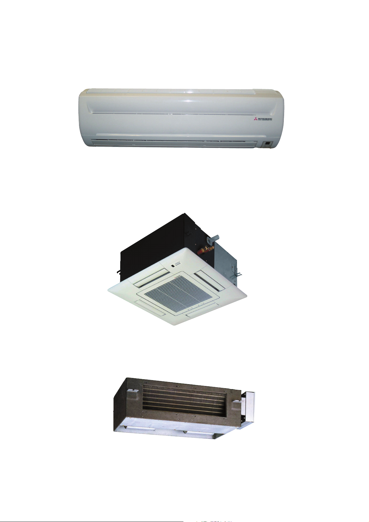
INDOOR UNIT
Models SKM22ZD-S, SKM25ZD-S, SKM28ZD-S, SKM35ZD-S,
Models SKM50ZD-S
Models STM25ZE-S, STM35ZE-S, STM50ZE-S, STM60ZE-S
Models SRRM25ZE-S, SRRM35ZE-S, SRRM50ZE-S, SRRM60ZE-S
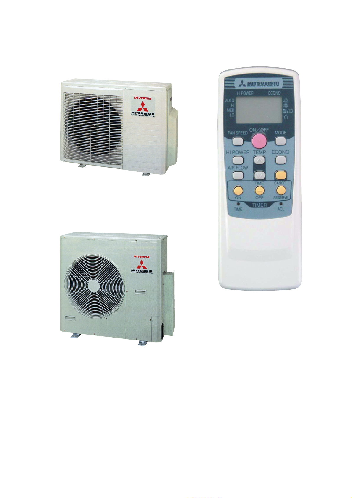
OUTDOOR UNIT
Models SCM45ZD-S, SCM60ZD-S
Model SCM80ZD-S
REMOTE CONTROLLER

1 GENERAL INFORMATION
1.1 Specific features
(1) The long piping makes the location of the inside and units flexible.
¡ No need for additional charge of refrigerant : 45 type · 20m, 60 type · 30m, 80 type · 40m
¡ Maximum piping length : 45 type · 30m, 60 type · 40m, 80 type · 60m
(2) Connectable indoor capacity
Number of connectable units : 45 type · 2 units, 60 type · 3 units, 80 type · 4 units
Total of indoor units (class kW) : 45 type · 7.0kw, 60 type · 10.6kw, 80 type · 13.4kw
(3) Indoor units are available with 5 capacities.
5 capacities................ 22, 25, 28, 35, 50, 60
Types ......................... Wall mounted type (SKM).
4-way ceiling cassette type (STM).
Ducted type (SRRM).
(4) Inverter (Frequency converter) for multi-steps power control
¡ Heating / Cooling
The rotational speed of a compressor is changed in step in relation to varying load, to interlock with the indoor and outdoor unit
fans controlled to changes in frequency, thus controlling the power.
¡ Allowing quick heating/cooling operation during start-up period. Constant room temperature by fine-tuned control after the
unit has stabilized.
(5) Fuzzy control
Fuzzy control calculates the amount of variation in the difference between the suction air temperature and the setting temperature
in compliance with the fuzzy rules in order to control the air capacity and the inverter frequency.
(6) Self diagnosis function
We are constantly trying to do better service to our customers by installing such judges that show abnormality of operation as
follows.
1.2 How to read the model name
Example : ST M 25 Z D - S
R410A models
Series No.
Inverter and Heat pump type
Product capacity
Multiple system
Model name
-
1
SK : Wall mounted type
ST : 4 way ceiling cassette type
SRR : Ducted type
SC : Outdoor unit
-
2 SELECTION DATA
2.1 Specifications
(1) Indoor unit
Models SKM22ZD-S, 25ZD-S, 28ZD-S, 35ZD-S
Models
Item
Cooling capacity W 2200 2500 2800 3500
Heating capacity W 3200 3400 4000 4500
Cooling
Noise level
Exterior dimensions
Height × Width × Depth
Color Cool white
Net weight kg 9.0
Air handling equipment
Fan type & Q’ty
Motor W 16
Air flow (at high)
Air filter, Q’ty
Operation switch Wireless-Remote controller
Room temperature control M.C thermostat
Pilot lamp RUN (Green), TIMER (Yellow), HI POWER (Green), ECONO (Orange)
Safety equipment
Refrigerant
piping
Drain hose Connectable
Accessories (including)
Optional parts —
Outdoor units to be combined SCM45ZD-S, SCM60ZD-S, SCM80ZD-S
Heating
O.D mm (in)
Connecting method Flare connecting
Attached length of piping Liquid line : 0.4m Gas line : 0.33m
Insulation Necessary (Both Liquid & Gas lines)
Sound level
Power level
Sound level
Power level
Cooling 8.0 8.2 8.4
Heating
Liquid line
Gas line
dB
mm 250 × 815 × 249
CMM
SKM22ZD-S SKM25ZD-S SKM28ZD-S SKM35ZD-S
Hi : 37 Me : 30 Lo : 23
Hi : 53 Hi : 54 Hi : 55
Hi : 39 Me : 33 Lo : 27
Hi : 55 Hi : 56 Hi : 57
8.7 9.0 9.2
Polypropylene net × 2 (Washable)
Frost protection, Serial error protection
Fan motor error protection
Mounting kit, Clean filter (Natural enzyme filter × 1, Photocatalytic washable deodorizing filter × 1)
Hi : 38 Me : 31 Lo : 24 Hi : 39 Me : 32 Lo : 25
Hi : 40 Me : 34 Lo : 28 Hi : 41 Me : 35 Lo : 29
Tangential fan × 1
φ 6.35 (1/4″)
φ 9.52 (3/8″)
Notes (1) The data are measured at the following conditions.
Operation DB WB DB WB
Cooling 27ºC 19ºC 35ºC 24ºC ISO-T1, JIS C9612
Heating 20ºC – 7ºC 6ºC ISO-T1, JIS C9612
(2) Capacity indicated is the rated capacity with one unit operating under ISO-T1 standards conditions.
Item Indoor air temperature Outdoor air temperature
-
-
2
Standards
Model SKM50ZD-S
Models
Item
Cooling capacity W 5000
Heating capacity W 5800
Noise level
Noise level
Exterior dimensions
Height × Width × Depth
Color Cool white
Net weight kg 9.5
Air handling equipment
Fan type & Q’ty
Motor W 29
Air flow (at high)
Air filter, Q’ty Polypropylene net × 2 (Washable)
Operation switch Wireless-Remote controller
Room temperature control M.C thermostat
Pilot lamp RUN (Green), TIMER (Yellow), HI POWER (Green), ECONO (Orange)
Safety equipment
Refrigerant
piping
Drain hose Connectable
Accessories (including)
Optional parts —
Outdoor units to be combined SCM60ZD-S, SCM80ZD-S
Power level Hi : 62
Power level Hi : 63
O.D mm (in)
Connecting method Flare connecting
Attached length of piping Liquid line : 0.4m Gas line : 0.33m
Insulation Necessary (Both Liquid & Gas lines)
Sound level
Cooling
Sound level Hi : 48 Me : 37 Lo : 27
Heating
Cooling 11
Heating
Liquid line
Gas line
dB
mm 250 × 815 × 249
CMM
Frost protection, Serial error protection
Fan moter error protection
Mounting kit, Clean filter (Natural enzyme filter × 1, Photocatalytic washable deodorizing filter × 1)
SKM50ZD-S
Hi : 47 Me : 36 Lo : 23
Tangential fan × 1
13.9
φ 6.35 (1/4″)
φ 12.7 (1/2″)
Notes (1) The data are measured at the following conditions.
Operation DB WB DB WB
Cooling 27ºC 19ºC 35ºC 24ºC ISO-T1, JIS C9612
Heating 20ºC – 7ºC 6ºC ISO-T1, JIS C9612
(2) Capacity indicated is the rated capacity with one unit operating under ISO-T1 standards conditions.
Item Indoor air temperature Outdoor air temperature
-
-
3
Standards
Models STM25ZE-S, 35ZE-S, 50ZE-S, 60ZE-S
Models
Item
Cooling capacity W 2500 3500 5000 6000
Heating capacity W 3400 4500 5800 6800
Cooling
Noise level
Exterior dimensions
Height × Width × Depth
Color
Net weight
Air handling equipment
Fan type & Q’ty
Motor W
Air flow (at high)
Air filter, Q’ty
Operation switch Wireless-Remote controller
Room temperature control M.C thermostat
Pilot lamp RUN (Green), TIMER (Yellow), HI POWER (Green), ECONO (Orange)
Safety equipment
Refrigerant
piping
Drain hose Connectable
Accessories (including) Mounting kit
Optional parts Wired remote controller
Outdoor units to be combined SCM45ZD-S, SCM60ZD-S, SCM80ZD-S SCM60ZD-S, SCM80ZD-S
Heating
O.D mm (in)
Connecting method Flare connecting
Attached length of piping —
Insulation Necessary (Both Liquid & Gas lines)
Sound level
Power level
Sound level
Power level
Main unit 248 × 570 × 570
Panel
Main unit
Panel 3.5
Cooling 7.7 8.5 9.4 13.0
Heating
Liquid line
Gas line
dB
mm
kg
CMM
STM25ZE-S STM35ZE-S STM50ZE-S STM60ZE-S
35 38 40 47
35 38 40 47
35 × 700 × 700
–
14 14.5
Turbo fan × 1
9.5 10.0 11.0 14.0
Long life filter
Frost protection, Serial error protection
Fan motor error protection, Drain error protection
φ 9.52 (3/8″) φ 12.7 (1/2″)
× 1
(Washable)
φ 6.35 (1/4″)
Notes (1) The data are measured at the following conditions.
Operation DB WB DB WB
Cooling 27ºC 19ºC 35ºC 24ºC ISO-T1, JIS C9612
Heating 20ºC – 7ºC 6ºC ISO-T1, JIS C9612
(2) Capacity indicated is the rated capacity with one unit operating under ISO-T1 standards conditions.
Item Indoor air temperature Outdoor air temperature
-
-
4
Standards
Models SRRM25ZE-S, 35ZE-S, 50ZE-S, 60ZE-S
Models
Item
Cooling capacity W 2500 3500 5000 6000
Heating capacity W 3400 4500 5800 6800
Cooling
Noise level
Exterior dimensions
Height × Width × Depth
Color —
Net weight kg 22.0 23.0
Air handling equipment
Fan type & Q’ty
Motor W
Air flow (at high)
Air filter, Q’ty
Operation switch Wireless-Remote controller
Room temperature control M.C thermostat
Pilot lamp RUN (Green), TIMER (Yellow), HI POWER (Green), ECONO (Orange)
Safety equipment
Refrigerant
piping
Drain hose Connectable
Accessories (including) Mounting kit
Optional parts Wired remote controller
Outdoor units to be combined SCM45ZD-S, SCM60ZD-S, SCM80ZD-S SCM60ZD-S, SCM80ZD-S
Heating
O.D mm (in)
Connecting method Flare connecting
Attached length of piping
Insulation Necessary (Both Liquid & Gas lines)
Sound level
Power level
Sound level
Power level
Cooling 7.6 7.8 9.6 11.4
Heating
Liquid line
Gas line
dB
mm 230 × 740 × 455
CMM
SRRM25ZE-S SRRM35ZE-S SRRM50ZE-S SRRM60ZE-S
38 40 46 49
39 41 46 49
Centrifugal fan × 2
9.9 10.7 13.2 15.2
PVC net
×
1
Frost protection, Serial error protection
Fan motor error protection, Drain error protection
φ 6.35 (1/4″)
φ 9.52 (3/8″) φ 12.7 (1/2″)
–
Notes (1) The data are measured at the following conditions.
Operation DB WB DB WB
Cooling 27ºC 19ºC 35ºC 24ºC ISO-T1, JIS C9612
Heating 20ºC – 7ºC 6ºC ISO-T1, JIS C9612
(2) Capacity indicated is the rated capacity with one unit operating under ISO-T1 standards conditions.
Item Indoor air temperature Outdoor air temperature
-
-
5
Standards
(2) Outdoor unit
Model SCM45ZD-S
Model
Item
Cooling capacity W 4500 (700 ~ 5600)
Heating capacity W 5600 (700 ~ 6800)
Power source 1 Phase 220/230/240V 50Hz
Power consumption
Running current
Noise level
Exterior dimensions
Height × Width × Depth
Color Stucco white
Net weight kg 44
Refrigerant equipment
Compressor type & Q’ty
Motor kW 0.7
Starting method Direct start
Refrigerant control Capillary tubes + Electric expansion valve
Refrigerant kg R410A 1.6 (Pre-charged up to the piping length of 20m)
Refrigerant oil R 0.48 (RB68A)
Air handling equipment
Fan type & Q’ty
Motor W 35
Air flow (at high) CMM 40
Shock & vibration absorber Rubber (for compressor)
Safety equipment
Size × Core × Number mm (in)
Refrigerant
piping
Power source supply Terminal block (Screw fixing type)
Connection wiring
Accessories (included) Installation sheet, Manual instruction
Indoor units to be combined STM25, 35 type,
Connecting method Flare connecting
Attached length piping —
Insulation Necessary (Both Liquid & Gas lines)
Size × Core number 1.5 mm2 × 4 cores (Including earth cable) × 2
Connecting method Terminal block (Screw fixing type)
Cooling
Heating 1540 (200 ~ 2340)
Cooling 6.4/6.1/5.9
Heating
Sound level
Power level
W
A
dB
mm 640 × 850 × 290
Cooling : 45/45/47 Heating : 47/47/49
Cooling : 60/60/62 Heating : 62/62/64
Compressor overheat protection, Overcurrent protection
Serial signal error protection
SCM45ZD-S
1390 (200 ~ 2160)
7.1/6.8/6.5
5CS102XFD [Scroll] × 1
Propeller fan × 1
Liquid line: φ 6.35 (1/4″) × 2
Gas line: φ 9.52 (3/8″) × 2
SKM22, 25, 28, 35 type,
SRRM25, 35 type
Notes (1) The data are measured at the following conditions.
Operation DB WB DB WB
Cooling 27ºC 19ºC 35ºC 24ºC ISO-T1, JIS C9612
Heating 20ºC – 7ºC 6ºC ISO-T1, JIS C9612
(2) The values for capacity and power consumption shown in a range ( ) indicate the minimum and maximum of the range.
(3) If the piping length exceeds 20 m, additional charging is required. (20g/m)
Item Indoor air temperature Outdoor air temperature
-
-
6
Standards
Model SCM60ZD-S
Model
Item
Cooling capacity W 6000 (1400~6900)
Heating capacity W 7000 (750~7200)
Power source 1 Phase 220/230/240V 50Hz
Power consumption
Running current
Noise level
Exterior dimensions
Height × Width × Depth
Color Stucco white
Net weight kg 51
Refrigerant equipment
Compressor type & Q’ty
Motor kW 1.3
Starting method Direct start
Refrigerant control Capillary tubes + Electronic expansion valve
Refrigerant kg R410A 2.2 (Pre-charged up to the piping length of 30m)
Refrigerant oil R 0.67 (MEL56)
Air handling equipment
Fan type & Q’ty
Motor W 45
Air flow (at high) CMM 42
Shock & vibration absorber Rubber (for compressor)
Safety equipment
Refrigerant
piping
Power source supply Terminal block (Screw fixing type)
Connection
wiring
Accessories (included)
Indoor units to be combined STM25, 35, 50, 60 type
Cooling
Heating 1740 (320~2700)
Cooling 8.5/8.2/7.8
Heating
Sound level Cooling : 48/48/50 Heating : 50/50/52
Power level
Size × Core × Number mm (in)
Connecting method Flare connecting
Attached length piping —
Insulation Necessary (Both Liquid & Gas lines)
Size × Core number 1.5 mm2 × 4 cores (Including earth cable) × 3
Connecting method Terminal block (Screw fixing type)
W
A
dB
mm
Cooling : 63/63/65 Heating : 65/65/67
TNB220FLBM1 [Twin rotary type] × 1
Compressor overheat protection, Overcurrent protection
Serial signal error protection
Installation sheet, Manual instruction
SCM60ZD-S
1860 (400~3000)
8.0/7.6/7.3
640 × 850 × 290
Propeller fan × 1
Liquid line: φ 6.35 (1/4″) × 3
Gas line: φ 9.52 (3/8″) × 3
Union : (φ 9.52 / φ 12.7) × 2
SKM22, 25, 28, 35, 50 type
SRRM25, 35, 50, 60 type
Notes (1) The data are measured at the following conditions.
Operation DB WB DB WB
Cooling 27ºC 19ºC 35ºC 24ºC ISO-T1, JIS C9612
Heating 20ºC – 7ºC 6ºC ISO-T1, JIS C9612
(2) The values for capacity and power consumption shown in a range ( ) indicate the minimum and maximum of the range.
(3) If the piping length exceeds 30 m, additional charging is required. (20g/m)
Item Indoor air temperature Outdoor air temperature
-
-
7
Standards
Model SCM80ZD-S
Model
Item
Cooling capacity W 8000 (1000~9300)
Heating capacity W 9500 (850~9700)
Power source 1 Phase 220/230/240V 50Hz
Power consumption
Running current
Noise level
Exterior dimensions
Height × Width × Depth
Color Polar white
Net weight kg 66
Refrigerant equipment
Compressor type & Q’ty
Motor kW 1.3
Starting method Direct start
Refrigerant control Capillary tubes + Electronic expansion valve
Refrigerant kg R410A 3.05 (Pre-charged up to the piping length of 40m)
Refrigerant oil R 0.67 (MEL56)
Air handling equipment
Fan type & Q’ty
Motor W 55
Air flow (at high) CMM 56
Shock & vibration absorber Rubber (for compressor)
Safety equipment
Size × Core × Number mm (in)
Refrigerant
piping
Power source supply Terminal block (Screw fixing type)
Connection
wiring
Accessories (included)
Indoor units to be combined STM25, 35, 50, 60 type
Connecting method Flare connecting
Attached length piping —
Insulation Necessary (Both Liquid & Gas lines)
Size × Core number 1.5 mm2 × 4 cores (Including earth cable) × 4
Connecting method Terminal block (Screw fixing type)
Cooling
Heating 2440 (300~3200)
Cooling 12.2/11.6/11.2
Heating
Sound level
Power level
W
A
dB
mm
Cooling : 51/51/52 Heating : 52/52/53
Cooling : 65/65/66 Heating : 66/66/67
TNB220FLBM1 [Twin rotary type] × 1
Compressor overheat protection, Overcurrent protection
Serial signal error protection
Installation sheet, Manual instruction
SCM80ZD-S
2650 (350~3200)
11.2/10.7/10.3
845 × 880 × 340
Propeller fan × 1
Liquid line: φ 6.35 (1/4″) × 4
Gas line: φ 9.52 (3/8″) × 4
Union : (φ 9.52 / φ 12.7) × 2
SKM22, 25, 28, 35, 50 type
SRRM25, 35, 50, 60 type
Notes (1) The data are measured at the following conditions.
Operation DB WB DB WB
Cooling 27ºC 19ºC 35ºC 24ºC ISO-T1, JIS C9612
Heating 20ºC – 7ºC 6ºC ISO-T1, JIS C9612
(2) The values for capacity and power consumption shown in a range ( ) indicate the minimum and maximum of the range.
(3) If the piping length exceeds 40 m, additional charging is required. (20g/m)
Item Indoor air temperature Outdoor air temperature
-
-
8
Standards
(3) Operation data
¡ The combinations of the indoor units is indicated by numbers. They are read as follows.
(Example) SKM22ZD-S / 22 SKM35ZD-S / 35
¡ The capacity of the indoor units is shown by rooms. If this exceeds the maximum capacity of the outdoor unit, the demand
capacity will be proportionally distributed.
¡ If units are to be combined, use the table below to make the proper selection.
Model SCM45ZD-S
(a) Heating
(220/230/240V)
Indoor unit
combination
1
room
2
room
22
25
28
35
22+22
22+25
22+28
22+35
25+25
25+28
25+35
Heating capacity (kW) Power consumption (W)
Room heating capacity (kW) Total capacity (kW)
A room
3.2
3.4
4.0
4.5
2.65
2.5
2.4
2.2
2.75
2.6
2.4
B room Min.
2.65
2.9
3.1
3.4
2.75
2.9
3.3
0.7
0.7
0.7
0.7
1.5
1.5
1.5
1.5
1.5
1.5
1.5
Standard
3.2
3.4
4.0
4.5
5.3
5.4
5.5
5.6
5.5
5.5
5.7
Max.
3.9
4.1
4.3
4.7
7.4
7.4
7.4
7.4
7.4
7.4
7.4
Min.
200
200
200
200
450
450
450
450
450
450
450
Standard
1120
1190
1400
1590
1430
1460
1490
1540
1490
1490
1570
1380
1450
1520
1660
2540
2540
2540
2540
2540
2540
2540
Running
current (A)
StandardMax.
5.1/4.9/4.7
5.5/5.2/5.0
6.4/6.1/5.9
7.3/7.0/6.7
6.6/6.3/6.0
6.7/6.4/6.1
6.8/6.5/6.3
7.1/6.8/6.5
6.8/6.5/6.3
6.8/6.5/6.3
7.2/6.9/6.6
28+28
28+35
35+35
2.8
2.6
2.95
2.8
3.2
2.95
1.5
1.5
1.5
5.6
5.8
5.9
-
-
9
7.4
7.4
7.4
450
450
450
1540
1600
1630
2540
2540
2540
7.1/6.8/6.5
7.3/7.0/6.7
7.5/7.2/6.9
 Loading...