

Page 1

RESIDENTIAL AIR-CONDITIONING
TECHNICAL MANUAL & PARTS LIST
INVERTER WALL MOUNTED TYPE
RESIDENTIAL AIR-CONDITIONER
(Split system, air to air heat pump type)
SRK92ZL-S
Manual No.'12•SRK-T-130
Page 2
TECHNICAL MANUAL
Page 3

'12 • SRK-T-130
'10 • SRK-T-105
CONTENTS
1. SPECIFICATION ........................................................................................ 3
(2) Outdoor unit ....................................................................................... 5
..................................................... 16
(3) Remote control
..................................................................................... 6
......................................................................... 4
(1) Indoor unit .......................................................................................... 4
2. EXTERIOR DIMENSIONS
3. ELECTRICAL WIRING .............................................................................. 8
(1) Indoor unit .......................................................................................... 8
4. NOISE LEVEL ............................................................................................ 10
(2) Outdoor unit ....................................................................................... 9
6. RANGE OF USAGE & LIMITATION
................................................................................... 18
7. CAPACITY TABLE
5. PIPING SYSTEM ...................................................................................... 15
.................................................................................. 19
8. APPLICATION DATA
9. OUTLINE OF OPERATION CONTROL BY MICROCOMPUTER ............... 30
(7) Timer operation
.................................................................................. 33
....................................................... 31
(1) Operation control function by remote control
(6) Flap and louver control ........................................................................... 32
(5) Selection of the annual cooling function .............................................. 32
(4) Custom cord switching procedure
......................................................................... 31(3) Auto restart function
(2) Unit ON/OFF button
........................................................................... 31
...................................... 30
(8) Outline of heating operation ................................................................ 34
(10) Outline of automatic operation ........................................................... 35
(9) Outline of cooling operation ............................................................... 35
(11) Protective control function
................................................................... 36
..................... 44
............................................................................... 43
(4) Troubleshooting procedure (If the air conditioner runs)
(3) Troubleshooting procedure
(If the air conditioner does not run at all)
........ 43
(1) Cautions
............................................................................................. 43
(2) Items to check before troubleshooting ................................................. 43
(5) Self-diagnosis table ............................................................................. 45
(6) Service mode (Trouble mode access function) ................................... 46
(7) Inspection procedures corresponding to detail of trouble .................... 54
10. MAINTENANCE DATA
(1) Installation of indoor unit ...................................................................... 19
(2) Installation of outdoor unit .................................................................. 23
-
-
1
Page 4
'10 • SRK-T-105
(10) How to make sure of wireless remote control ..................................... 60
(11) Outdoor unit inspection points .............................................................. 61
(8)
Phenomenon observed after shortcircuit, wire breakage on sensor
......... 58
(9) Checking the indoor electrical equipment
........................................... 59
■How to read the model name
Example: SRK 92 Z
Series code
Inveter type
Product capacity
Model name SRK : Wall mounted type
SRC : Outdoor unit
L-S
......................................................................................... 63
11. OPTION PARTS
.............................................................. 63
(1) Wired remote control (RC-E5)
..................................................................... 69
(2) Interface kit (SC-BIKN-E)
(3) Super link E board (SC-ADNA-E) ......................................................... 73
'12 • SRK-T-130
-
-
2
Page 5
'12 • SRK-T-130
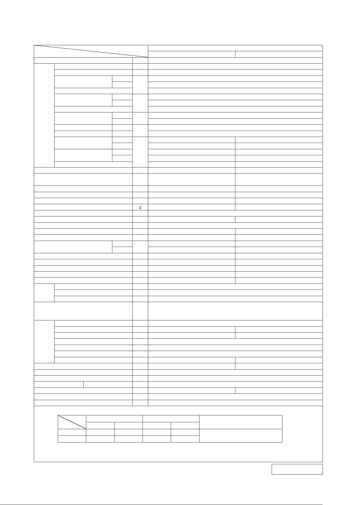
1. SPECIFICATION
Item
Power source 1 Phase, 220~240V, 50Hz
Nominal cooling capacity (range) kW 9.2 ( 2.4 (Min.) - 10.0 (Max.))
Nominal heating capacity (range) kW 10.0 ( 2.2 (Min.) - 11.2 (Max.))
Powe
consumption
Max power consumption 3.80
Running
current
Operation
data
Exterior dimensions (Height x Width x Depth) mm 318 x 1098 x 248 970 x 1300 x 370
Exterior appearance
( Munsell colour )
Net weight kg 15 91
Compressor type & Q'ty — RMT5126MCE1( Twin Rotary type ) x 1
Compressor motor (Starting method) kW — 4.0 ( Inverter driven )
Refrigerant oil (amount, type) — 0.90 ( DIAMOND FREEZE MA68 )
Refrigerant (Type, amount, pre-charge length) kg R410A 3.15 ( Pre-Charged up to the piping length of 15m )
Heat exchanger Louver fins & inner grooved tubing M fins & inner grooved tubing
Refrigerant control Capillary tubes + Electronic expansion valve
Fan type & Q'ty Tangential fan x 1 Propeller fan x 2
Fan motor (Starting method) W 56 x 1 ( Direct drive ) 86×2 ( Direct drive )
Air flow
Available external static pressure Pa 0 0
Outside air intake Not possible —
Air filter, Quality / Quantity Polypropylene net ( washable ) x 2 —
Shock & vibration absorber Rubber sleeve ( for fan motor )
Electric heater — —
Operation
control
Safety equipments
Installation
data
Drain pump, max lift height mm — —
Recommended breaker size A 20
L.R.A. (Locked rotor ampere) A 13.3 / 12.7 / 12.2 (220/ 230/ 240 V)
Connection wiring Size x Core number 1.5mm2 x 4 cores ( Including earth cable ) / Terminal block ( Screw fixing type )
IP number IPX0 IPX4
Standard accessories
Option parts Interface kit ( SC-BIKN-E )
Inrush current, max current 13.3 / 12.7 / 12.2 (220/ 230/ 240 V) Max. 17.5
Power factor
EER Cooling 3.62
COP Heating 3.52
Sound power level
Sound pressure level
Silent mode sound pressure level — —
Remote control Wireless-Remote control
Room temperature control Microcomputer thermostat
Operation display RUN: Green , TIMER: Yellow , HI POWER: Green ,ECONO: Orange
Refrigerant piping size ( O.D ) mm Liquid line: φ6.35 ( 1/4" ) Gas line: φ15.88 ( 5/8" )
Connecting method Flare connection Flare connection
Attached length of piping m Liquid line : 0.70 / Gas line : 0.63 —
Insulation for piping Necessary ( Both sides ), independent
Refrigerant line (one way) length m Max.30
Vertical height diff. between O.U. and I.U.
Drain hose Hose connectable ( VP 16 ) Holes φ20 x 3 pcs
Notes (1) The data are measured at the following conditions. The pipe length is 7.5m.
Item
Indoor air temperature Outdoor air temperature
Operation
Cooling
Heating 20˚C
(2) This air-conditioner is manufactured and tested in conformity with the ISO.
(3) Sound level indicates the value in an anechoic chamber. During operation these value are somewhat higher due to ambient conditions.
(4) Select the breaker size according to the own national standard.
Cooling
Heating 2.84 ( 0.43 ~ 3.76 )
Cooling
Heating 13.3 / 12.7 / 12.2 (220/ 230/ 240 V)
Cooling
Heating 97
Cooling
Heating 64 67
Cooling Hi: 51 Me: 47 Lo: 41 Ulo: 26 53
Heating Hi: 49 Me: 46 Lo: 42 Ulo: 38 54
Cooling
Heating Hi: 23.5 Me: 20.5 Lo: 17.0 Ulo: 15.0 100
DB WB DB WB
27˚C 19˚C 35˚C 24 ˚C
Model
kW
A
%
dB(A)
m3/min
m Max.20 ( Outdoor unit is higher ) / Max.20 ( Outdoor unit is lower )
ー
Indoor unit SRK92ZL-S Outdoor unit SRC92ZL-S
11.9 / 11.4 / 10.9 (220/ 230/ 240 V)
65 67
Fine snow
( 8.0Y 9.3/0.1 ) near equivalent
Hi: 21.0 Me: 18.5 Lo: 15.0 Ulo: 8.0 105
Compressor overheat protection, Overcurrent protection,
Frost protection, Serial signal error protection, Indoor fan motor error protection,
Heating overload protection( High pressure control ), Cooling overload protection
Mounting kit, Clean filter ( Allergen clear filter x 1, Photocatalytic washable deodorizing filter x 1 )
7˚C 6˚C
SRK92ZL-S
2.54 ( 0.47 ~ 3.07 )
97
Rubber sleeve ( for fan motor & compressor )
Standards
ISO5151-T1
Adapted to RoHS directive
Stucco white
( 4.2Y 7.5/1.1 ) near equivalent
RWA000Z235
-
-
3
Page 6
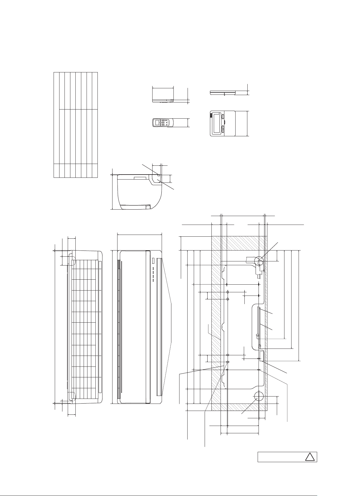
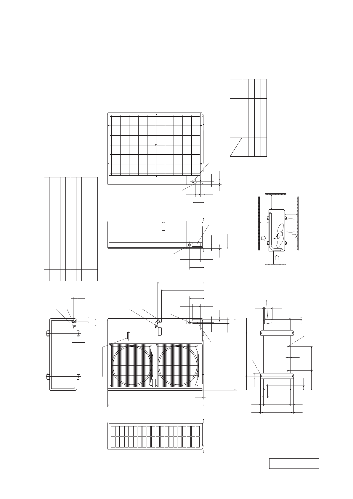
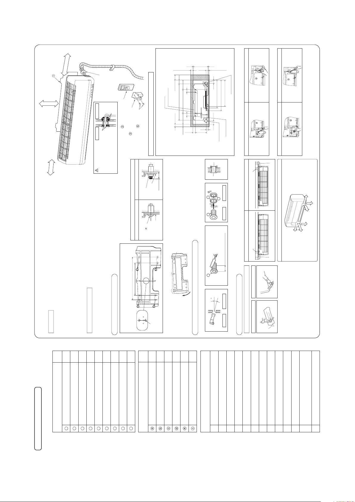
2. EXTERIOR DIMENSIONS
Outlet for down piping
(Refer to the above view)
Hole on wall for right rear piping
Hole on wall for left rear piping
Gas piping
Outlet for piping(on both side)
Drain hose
Outlet for wiring
Liquid piping
FGECD
B
Symbol
A
(φ65)
VP16
φ6.35(1/4")(Flare)
Content
φ15.88(5/8")(Flare)
(φ65)
Note(1)The model name label is attached
on the underside of the panel.
D
C
B
A
E
Wireless remote control
Wired Remote control
(Option)
G
F
Unit:mm
7753.5
633.5
703.5
792
15
7.7
44.5
44.5
301.8 8.5
5050
450349 299
106886106
65
100
50
49.5221.5
25
25
(Service space)
(Service space)
(Service space)
Unit
Installation plate
Space for installation and service when viewing from the front
6-5X17.5(Slot hole)
43
4-12X18(Slot hole)
(Service space)
244 610 244
225
46
1098
318
3248
410904
60
55
19
55
55
43.564
9
60
150
17.3
120
19
(1) Indoor unit
Model SRK92ZL-S
'12 • SRK-T-130
-
-
4
RKW000Z402
A
Page 7
L1
L3
Intake
L2
Intake
Outlet
L4
space
Service
B
A
E
C
D
F
C
C
F
C
F
B
A
Minimum installation space
φ
15.88(5/8")(Flare)
Content
C Pipe/cable draw-out hole
D
E Anchor bolt hole
Drain discharge hole
Symbol
B
A
M10
×
4places
φ20×3places
Service valve connection(liquid side)
φ
6.35(1/4")(Flare)
Unit:mm
Service valve connection of the
attached connecting pipe(gas side)
41
51
40
103
60
262 325
38
15
60
15
103
200580190
55
40370
40
41020 20
76
L2
L3
L4
L1
300
100
250
Open
Open
250
100
500
Open
250
150
250
Examples of
Dimensions
installation
The height of a wall is 1200mm or less
Terminal block
67
9
150
7050
195
11050
50
27
50
1300
10
970
55
15
50
195
11050
41
F Cable draw-out hole
φ30(front)
φ45(side)
φ50(back)
626
574
Ⅰ Ⅱ
Ⅲ
Notes
(1) It must not be surrounded by walls on the four sides.
(2) The unit must be fixed with anchor bolts. An anchor bolt must not
protrude more than 15mm.
(3) Where the unit is subject to strong winds, lay it in such
a direction that the blower outlet faces perpendicularly
to the dominant wind direction.
(4) Leave 1m or more space above the unit.
(5) A wall in front of the blower outlet must not exceed the units height.
(6) The model name label is attached on the rear panel.
(2) Outdoor unit
Model SRC92ZL-S
'12 • SRK-T-130
RCR0 00Z006
-
-
5
Page 8
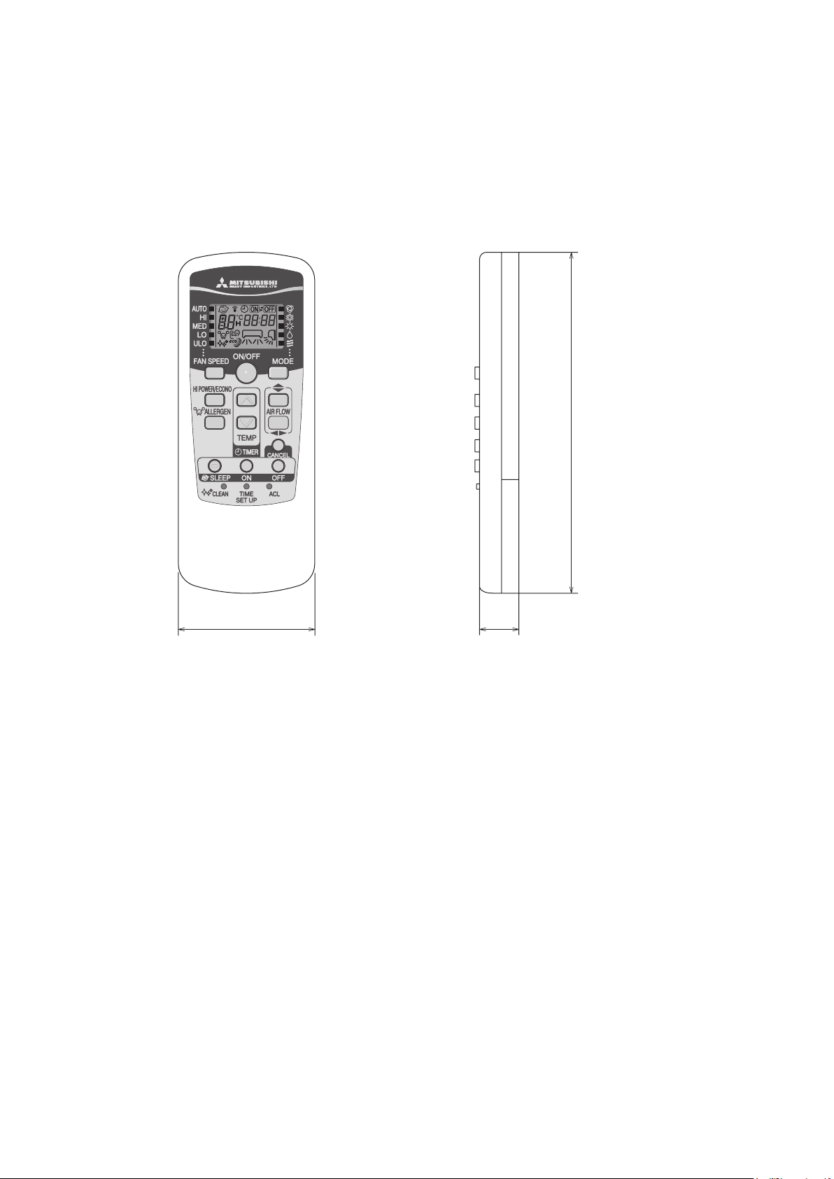
(3) Remote control
Unit: mm
60
17.3
150
(a) Wireless remote control
'12 • SRK-T-130
-
-
6
Page 9
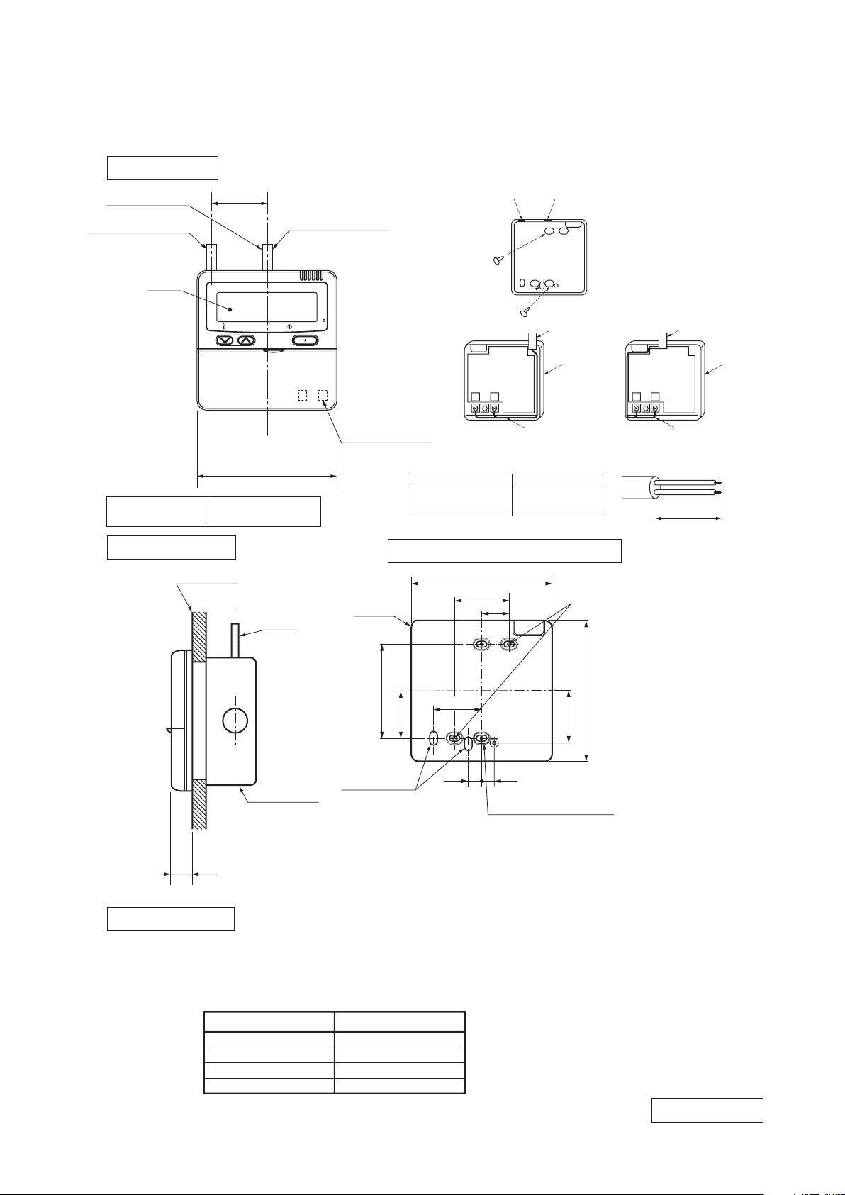
(b) Wired remote control (option parts)
TEMP ON/OFF
48
□120
L C D
Wall surface
Wiring
Electrical box
(Not included)
19
Wiring specifications
Exposed mounting
23
46
11.5 11
Remote
control
outline
120
45
83.5
42
120
Remote control installation dimensions
Wiring oulet
Installation hole
12×7 Slot hole
9.5×5 Slot hole (4places)
(1) Installation screw for remote control
M4 Screw (2 pieces)
44
(1) If the prolongation is over 100m, change to the size below.
But, wiring in the remote control case should be under 0.5mm2. Change the wire size outside of
the case according to wire connecting. Waterproof treatment is necessary at the wire connecting
section. Be careful about contact failure.
Length Wiring thickness
100 to 200m
0.5mm2×2 cores
0.75mm2×2 cores
1.25mm2×2 cores
2.0mm2×2 cores
Under 300m
Under 400m
Under 600m
Upper part
Lower part
Lower case
Sheath
Upper cace
Board
Wiring
Upper
Lower
X Y
Sheath
Upper cace
Board
Wiring
Upper
Lower
YX
Tighten the screws after
cutting off the thin part of
screw mounting part.
Embedded mounting
The peeling-off length of sheath
The peeling-off length
of sheath
In case of pulling out from
upper left
In case of pulling out
from upper left
In case of pulling out
from upper left
X wiring : 170mm
Y wiring : 190mm
Pulling out from center
X wiring : 215mm
Y wiring : 195mm
Pulling out from upper left
Exterior appearance
(Munsell color)
Pearl White
(N8.5) near equivalent
In case of pulling out from center
In case of pulling out
from center
In case of pulling out
from center
Wiring outlet
Cut off the upper thin part of remote control lower case with a nipper or knife,
and grind burrs with a file etc.
0.3mm2×2 cores.
X, Y Terminal block
Attach M3 screw
with washer
Unit:mm
Interface kit (SC-BIKN-E) is required to use the wired remote control.
'12 • SRK-T-130
-
-
7
PJZ0 00Z274
Page 10
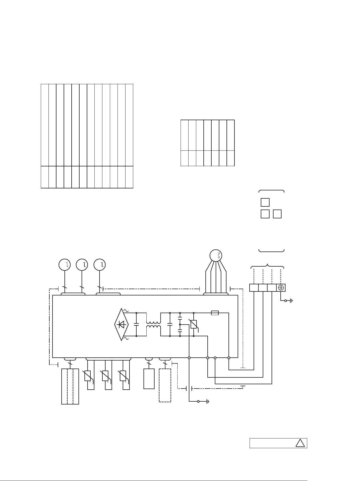
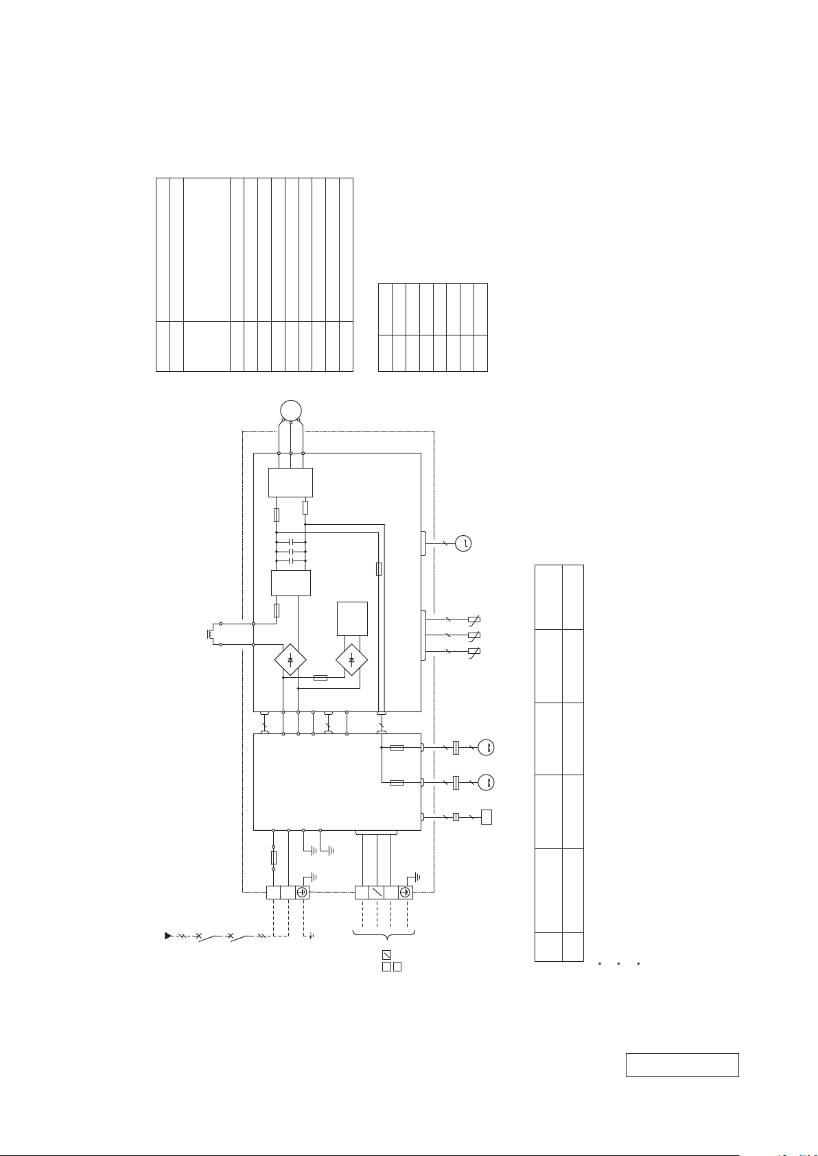
3. ELECTRICAL WIRING
250V
F
G
3.15A
S/N
Va
CNU
CNS
INTERFACE KIT
SC-BIKN-E
CNG
CNE
DISPLAY
WIRELESS RECEIVER
J
CNF
U
M
HEAT
13456
BACK-UP SW
5
2
EXCHANGER
L
Th1
BOARD
CIRCUIT
PRINTED
CNX2
CNX1
M
M
M
5
5
5
RD
WH
RD
WHBKBL
Y
Y/G
BK
t
Th21Th2
2
Th3
LM1
LM2
SM1
FMI
DS
t
t
TO OUTDOOR UNIT
HEAT
EXCHANGER
1
2/N
3
POWER WIRES
SIGNAL WIRE
1
2/N
3
Power source
~220/230/240V 50Hz
T
8
Color Marks
Blue
BlackBK
Red
BL
RD
WhiteWH
Yellow/Green
Y/G
YellowY
ColorMark
Heat exch. sensor
Humidity sensor
Fan motor
Room temp. sensor
Flap motor
Th1
Th2
1,2
Th3
Diode stackDS
FuseF
Connector
CNE-CNX2
FMI
Terminal blockT
Louver motorLM
1,2
SM
1
Description
Item
VaristorVa
(1) Indoor unit
Model SRK92ZL-S
'12 • SRK-T-130
8
-
RWA000Z402
A
-
Page 11
'12 • SRK-T-130
Color
RD
Mark
OrangeOR
Yellow/GreenY/G
BlackBK
BrownBR
YellowY
WhiteWH
Red
DescriptionItem
Connector
CN20S
Electric expansion valve(coil)
EEV
Fan motor 1
FMo1
ReactorLTerminal block
TB1,2
Compressor motor
CM
Solenoid valve for 4 way valve
20S
Heat exchanger sensor(outdoor unit)
TH2
Outdoor air temp.sensor
TH3
TH4
Discharge pipe temp.sensor
CNTH
CNEEV
CNFAN1,2
Fan motor 2
FMo2
POWER
Model
Power cable, indoor-outdoor connecting wires
The specifications shown in the above table are for units without heaters. For units with heaters, refer
to the installation instructions or the construction instructions of the indoor unit.
Switchgear of Circuit breaker capacity which is calculated from MAX. over current should be chosen
along the regulations in each country.
The cable specifications are based on the assumption that a metal or plastic conduit is used with no
more than three cables contained in a conduit and a voltage drop is 2%. For an installation falling
outside of these conditions, please follow the internal cabling regulations. Adapt it to the regulation
in effect in each country.
17.5 2.5 30 1.5mm
2
x 4 1.592
3
1
2
N
~220/230/240V 50Hz
TO INDOOR UNIT
POWER WIRES
SIGNAL WIRE
M
T2
T1
S
(BK)
(WH)
(RD)
VWU
PWB ASSY(MAIN)PWB1
M
+ +
R
TRANSISTOR
POWER
CIRCUIT
SWITCHING
250V 3.15A
F1
250V 20A
F2
F3 250V 3.15A
W
V
U
P
N
CNTH
CNEEV
t゜
3~
+
ACTIVE
FILTER
UNIT
250V 20A
F8
L
(OR)
(YE)
S-2
(BK)
(WH)
(WH)
PWB ASSY(SUB)PWB2
S-1
CNSUB
CNMAIN
250V 1A
F1
SINR
IN
(BK)
(WH)
G1
(Y/G)
S0
R0
N
L
250V 20A
FUSE
2
1
N
3
(Y/G)
CN20S
C-2
(RD)
20S
(RD)
TB1
TB2
TERMINAL
BLOCK
2 2
2
TH2 TH3 TH4
EEV
CM
BLOCK
TERMINAL
t゜
t゜
POWER
C-1
(WH)
(WH)
M M
250V 1A
F2
CNFAN1 CNFAN2
5
5
5
5
2
2
(BK)
(BK)
(WH)
(RD)
(RD)
(WH)(WH)
CN20V
(WH)
CN20V
4
(WH)
4
2
CNFAN
CNFAN0
(WH)
(BK)
(WH)
CNA
(WH)
(Y/G)
5
G3
(Y/G)
(WH)
(WH)
(WH)
FMo1 FMo2
MAX running current
Power cable size
(mm
2
)
(A)
Power cable length
(m)
indoor-outdoor
wire size x number
Earth wire size
(mm
2
)
[ ]
(2) Outdoor unit
Model SRC92ZL-S
RWC0 00Z260
-
-
9
Page 12
'12 • SRK-T-130
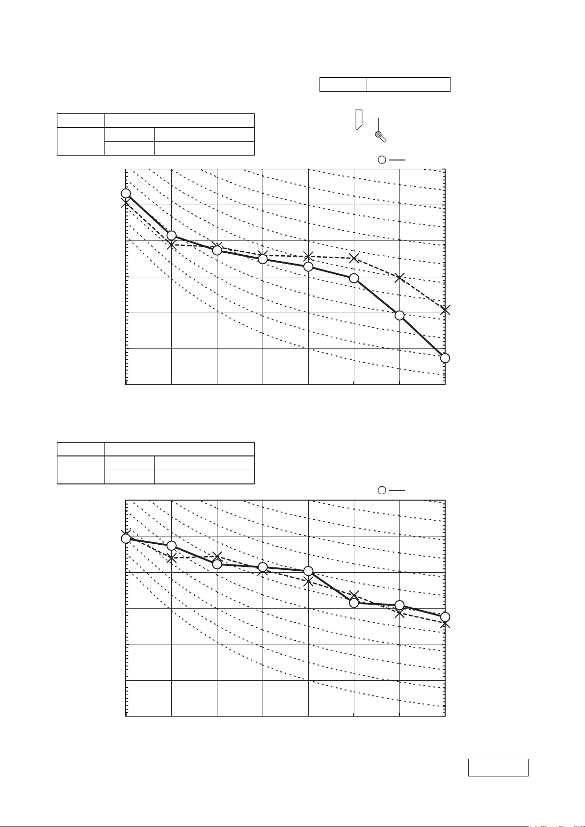
●
Mike position as below
0.8m
1m
Unit
Mike position
(Center & Low points)
●
Mike position: at highest noise level in position as mentioned below
Distance from front side 1m
●
Mike position as below
0.8m
1m
Unit
Mike position
(Center & Low points)
/KF1EVCXG$CPFHTGSWGPE[*\
0
0
0
0
0
0
5QWPF2TGUUWTG.GXGNF$
UVCPFCTF
2C
/KF1EVCXG$CPFHTGSWGPE[*\
0
0
0
0
0
0
5QWPF2TGUUWTG.GXGNF$
UVCPFCTF
2C
/KF1EVCXG$CPFHTGSWGPE[*\
0
0
0
0
0
0
5QWPF2TGUUWTG.GXGNF$
UVCPFCTF
2C
4. NOISE LEVEL
(1) Rated capacity value
(Indoor Unit)
Model SRK92ZL-S
Noise
Level
Cooling 51 dB(A)
Heating 48 dB(A)
Condition ISO-T1,JIS C9612
......
×
Cooling Heating
(Outdoor Unit)
Model SRC92ZL-S
Noise
Level
Cooling 53 dB(A)
Heating 54 dB(A)
-
10
......
×
Cooling Heating
-
ISC1 2092
Page 13

'12 • SRK-T-130
●
Mike position as below
0.8m
1m
Unit
Mike position
(Center & Low points)
/KF1EVCXG$CPFHTGSWGPE[*\
0
0
0
0
0
0
5QWPF2TGUUWTG.GXGNF$
UVCPFCTF
2C
/KF1EVCXG$CPFHTGSWGPE[*\
0
0
0
0
0
0
5QWPF2TGUUWTG.GXGNF$
UVCPFCTF
2C
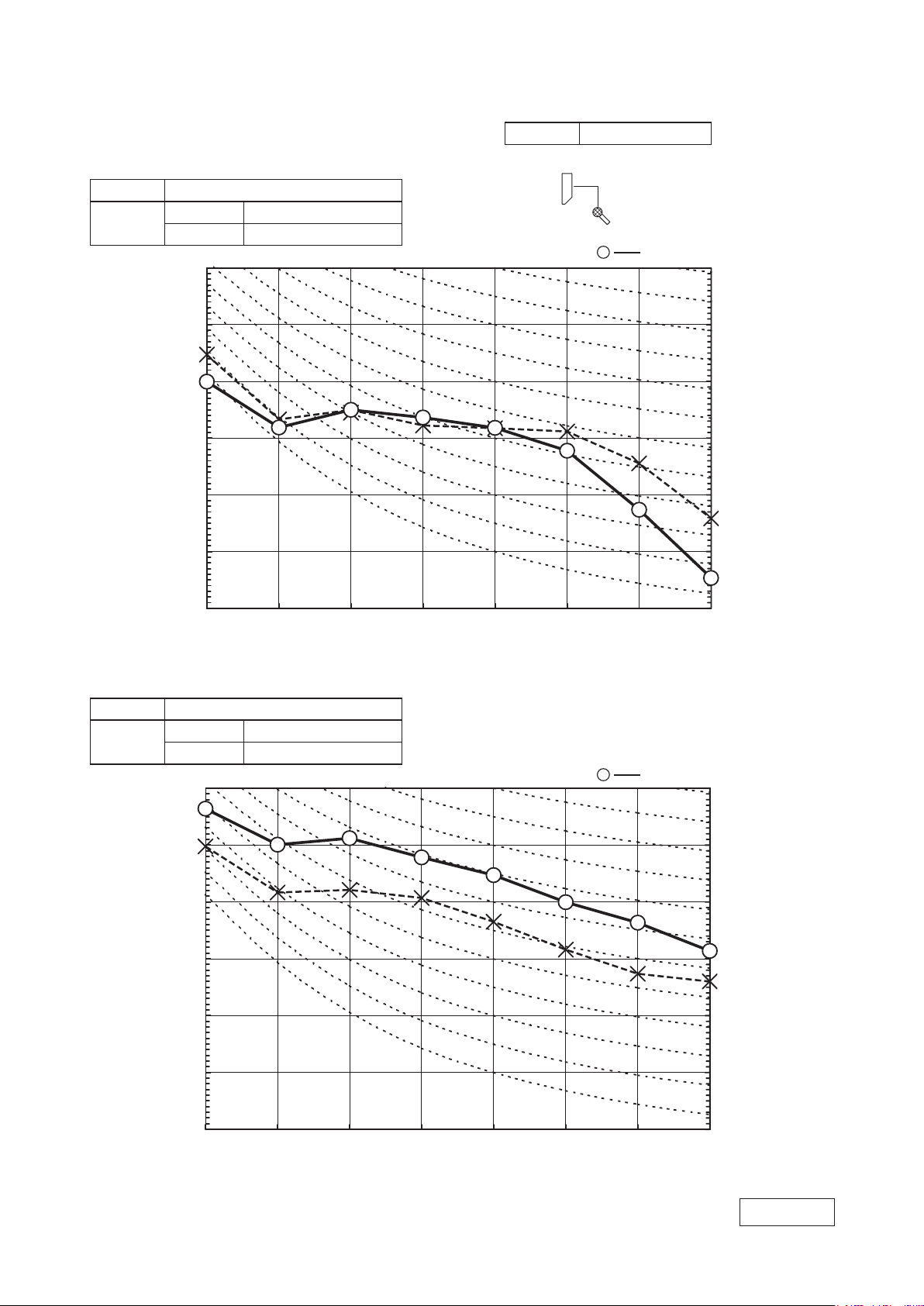
●
Mike position: at highest noise level in position as mentioned below
Distance from front side 1m
●
Mike position as below
0.8m
1m
Unit
Mike position
(Center & Low points)
(2) Max value in Hi MODE
(Indoor Unit)
Model SRK92ZL-S
Noise
Level
Cooling 51 dB(A)
Heating 49 dB(A)
Condition ISO-T1,JIS C9612
......
×
Cooling Heating
(Outdoor Unit)
Model SRC92ZL-S
Noise
Level
Cooling 58 dB(A)
Heating 60 dB(A)
......
×
Cooling Heating
-
11
ISC1 2092
-
Page 14
'12 • SRK-T-130
●
Mike position as below
0.8m
1m
Unit
Mike position
(Center & Low points)
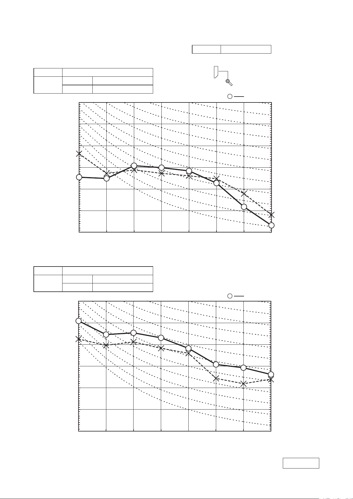
●
Mike position: at highest noise level in position as mentioned below
Distance from front side 1m
●
Mike position as below
0.8m
1m
Unit
Mike position
(Center & Low points)
/KF1EVCXG$CPFHTGSWGPE[*\
0
0
0
0
0
0
5QWPF2TGUUWTG.GXGNF$
UVCPFCTF
2C
/KF1EVCXG$CPFHTGSWGPE[*\
0
0
0
0
0
0
5QWPF2TGUUWTG.GXGNF$
UVCPFCTF
2C
/KF1EVCXG$CPFHTGSWGPE[*\
0
0
0
0
0
0
5QWPF2TGUUWTG.GXGNF$
UVCPFCTF
2C
(3) Max value in Me MODE
(Indoor Unit)
Model SRK92ZL-S
Noise
Level
Cooling 47 dB(A)
Heating 46 dB(A)
(Outdoor Unit)
Model SRC92ZL-S
Noise
Level
Cooling 52 dB(A)
Heating 60 dB(A)
Condition ISO-T1,JIS C9612
......
×
Cooling Heating
......
×
Cooling Heating
-
12
-
ISC1 2092
Page 15
'12 • SRK-T-130
●
Mike position as below
0.8m
1m
Unit
Mike position
(Center & Low points)
●
Mike position: at highest noise level in position as mentioned below
Distance from front side 1m
●
Mike position as below
0.8m
1m
Unit
Mike position
(Center & Low points)
/KF1EVCXG$CPFHTGSWGPE[*\
0
0
0
0
0
0
5QWPF2TGUUWTG.GXGNF$
UVCPFCTF
2C
/KF1EVCXG$CPFHTGSWGPE[*\
0
0
0
0
0
0
5QWPF2TGUUWTG.GXGNF$
UVCPFCTF
2C
/KF1EVCXG$CPFHTGSWGPE[*\
0
0
0
0
0
0
5QWPF2TGUUWTG.GXGNF$
UVCPFCTF
2C
(4) Max value in Lo MODE
(Indoor Unit)
Model SRK92ZL-S
Noise
Level
Cooling 41 dB(A)
Heating 42 dB(A)
Condition ISO-T1,JIS C9612
......
×
Cooling Heating
(Outdoor Unit)
Model SRC92ZK-S
Noise
Level
Cooling 50 dB(A)
Heating 54 dB(A)
......
×
Cooling Heating
-
13
-
ISC1 2092
Page 16
'12 • SRK-T-130
●
Mike position as below
0.8m
1m
Unit
Mike position
(Center & Low points)
●
Mike position: at highest noise level in position as mentioned below
Distance from front side 1m
●
Mike position as below
0.8m
1m
Unit
Mike position
(Center & Low points)
/KF1EVCXG$CPFHTGSWGPE[*\
0
0
0
0
0
0
5QWPF2TGUUWTG.GXGNF$
UVCPFCTF
2C
/KF1EVCXG$CPFHTGSWGPE[*\
0
0
0
0
0
0
5QWPF2TGUUWTG.GXGNF$
UVCPFCTF
2C
/KF1EVCXG$CPFHTGSWGPE[*\
0
0
0
0
0
0
5QWPF2TGUUWTG.GXGNF$
UVCPFCTF
2C
(5) Max value in ULo MODE
(Indoor Unit)
Model SRK92ZL-S
Noise
Level
Cooling 26 dB(A)
Heating 38 dB(A)
Condition ISO-T1,JIS C9612
......
×
Cooling Heating
(Outdoor Unit)
Model SRC92ZL-S
Noise
Level
Cooling 42 dB(A)
Heating 51 dB(A)
-
14
......
×
Cooling Heating
-
ISC1 2092
Page 17

5. PIPING SYSTEM
Model SRK92ZL-S
Indoor unit
Outdoor unit
Flare
connection
Flare connection
Liquid
pipe
Gas pipie
Service valve
Heat
exchanger
Heat
exchanger
sensor
Electronic
expansion valve
(Liquid)
Strainer
Receiver
Strainer
Capillary tube
Outdoor air
temp. sensor
Muffler
Compressor
Discharge pipe
temp. sensor
Cooling cycle
Heating cycle
Check joint
4way valve
Service valve
Heat
exchanger
sensor
(Th22)
(TH4)
Room temp.
sensor
(Th1)
Humidity
sensor
(Th3)
(Th21)
(
Gas
)
(TH3)
Heat
exchanger
sensor
(TH2)
(EEV)
Capillary tube
Heat
exchanger
Accumlator
Accumlator
Model SRK92ZL-S
'12 • SRK-T-130
-
15
-
Page 18
6. RANGE OF USAGE & LIMITATION
6. RANGE OF USAGE & LIMITATIONS
Indoor return air temperature
(Upper, lower limits)
Refrigerant line (one way) length
Power source voltage Rating ±10%
Voltage at starting Min. 85% of rating
Frequency of ON-OFF cycle
Max. 6 times/h
(Inching prevention 6 minutes)
ON and OFF interval Min. 3 minutes
Outdoor air temperature
(Upper, lower limits)
Vertical height difference between
outdoor unit and indoor unit
Max. 30m
Max. 20m (Outdoor unit is higher)
Max. 20m (Outdoor unit is lower)
Item
Model
SRK92ZL-S
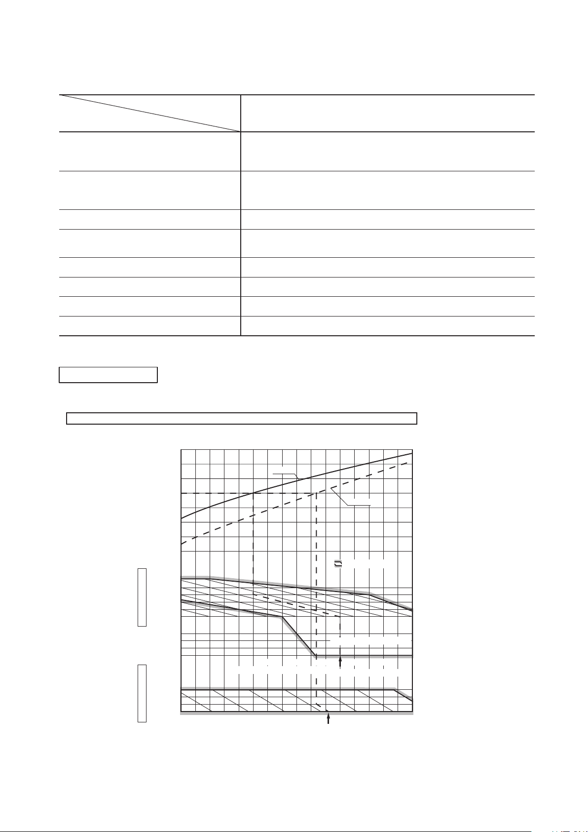
Cooling operation : Approximately 18 to 32℃ D.B.
Heating operation : Approximately 15 to 30℃ D.B.
(Refer to the selection chart)
Cooling operation : Approximately -15 to 46℃ D.B.
Heating operation : Approximately -15 to 24℃ D.B.
(Refer to the selection chart)
Selection chart
Correct the cooling and heating capacity in accordance with the conditions as follows. The net cooling and heating capacity can be
obtained in the following way.
Net capacity = Capacity shown on specification ×Correction factors as follows.
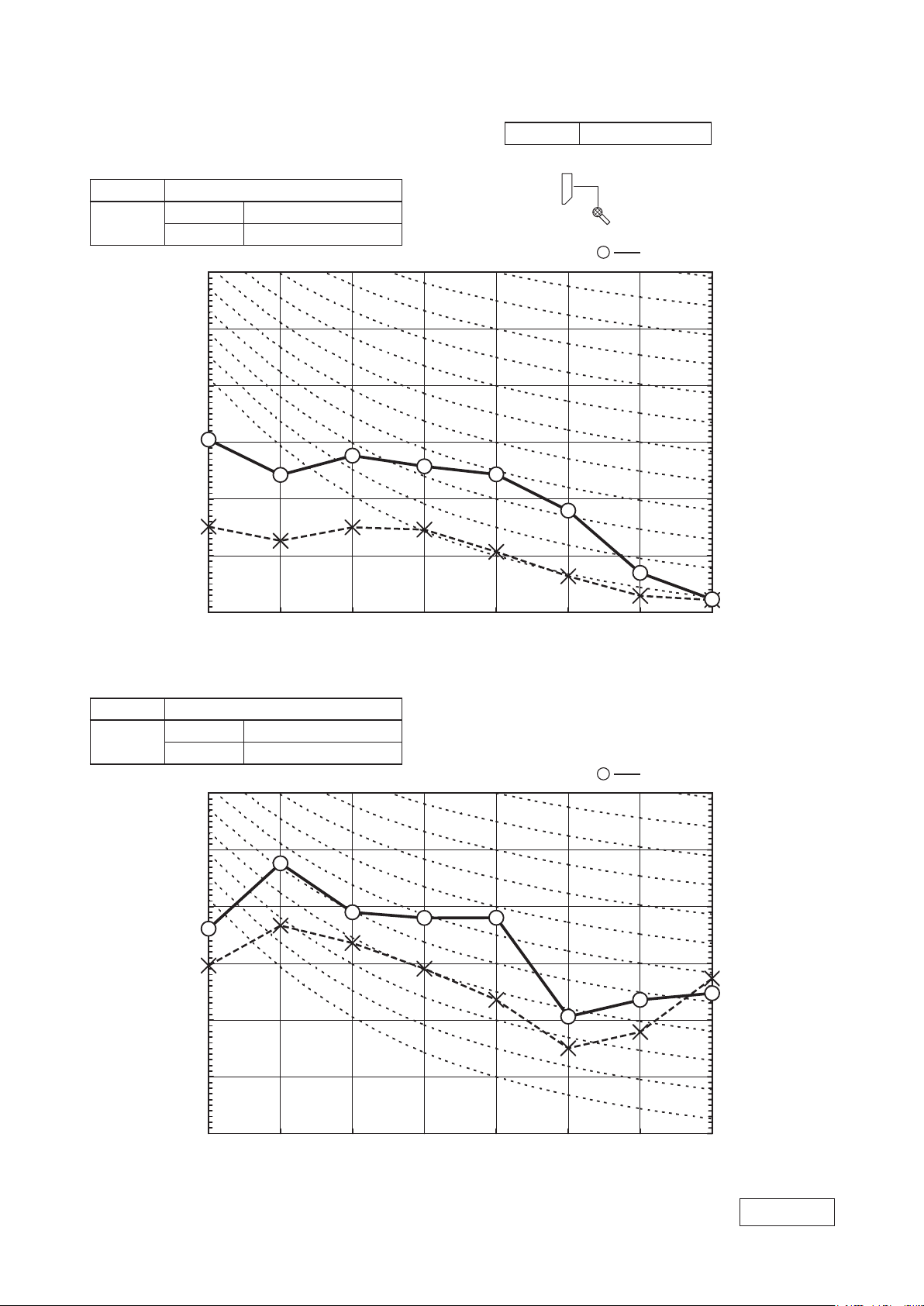
(1) Coefficient of cooling and heating capacity in relation to temperatures
SRK25ZJP-S1,35ZJP-S1 SRK50ZJP-S1
Net capacity = Capacity shown on specification Correction factors as follows.
(1) Coefficient of cooling and heating capacity in relation to temperatures
7
0.6
0.7
0.8
0.9
1.0
1.2
1.1
1.3
0
-5
-10
-15
24
26
20
25
30
35
40
46
15
20
25
30
Outdoor air W.B. temperature °C W.B.
-10 -5 0 5 10 15
.
Cooling operation
Outdoor air D.B.
temperature
°C D. B.
Coefficient of cooling
&
Heating capacity in
relation to temperature
Heating operation
Indoor air D.B.
temperature
°C D. B.
ISO-T1 Standard Condition
Depends on installed situation
ISO-T1 Standard Condition
2220181614
Indoor air W.B. temperature °C W.B
Applicable range
Cooling
Heating
'12 • SRK-T-130
-
16
-
Page 19
'09•SRK-DB-087D
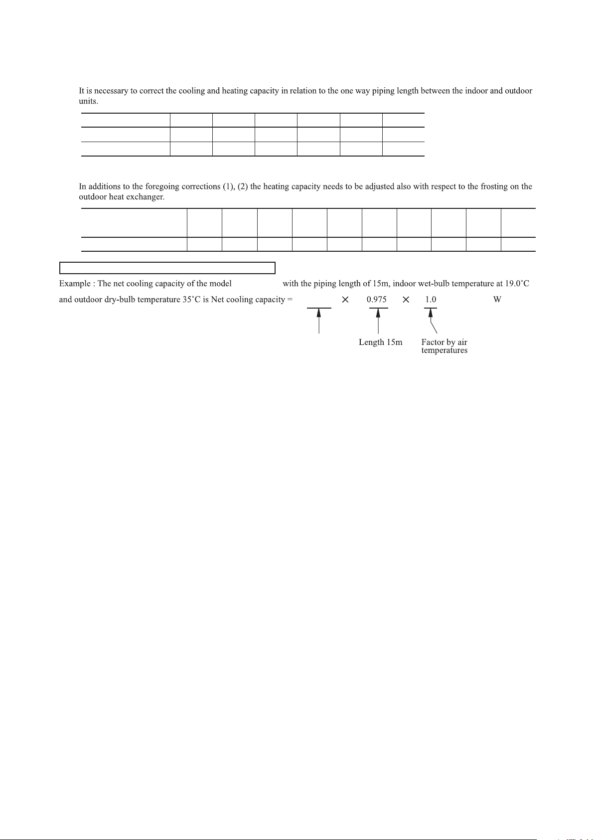
(2) Correction of cooling and heating capacity in relation to one way length of refrigerant piping
(3) Correction relative to frosting on outdoor heat exchanger during heating
How to obtain the cooling and heating capacity
=
Piping length [m]
Cooling
Heating
7
1.0
1.0
10
0.99
1.0
15
0.975
1.0
20
0.965
1.0
25
0.95
1.0
30
0.935
1.0
Air inlet temperature of
outdoor unit in °C WB
Adjustment coefficient
-15
0.95 0.95 0.94 0.93 0.91 0.88 0.86 0.87 0.92 1.00
-10 -9 -7 -5 -3 -1 1 3
5 or more
SRK92ZL-S
9200
SRK92ZL-S
8970
'12 • SRK-T-130
-
17
-
Page 20
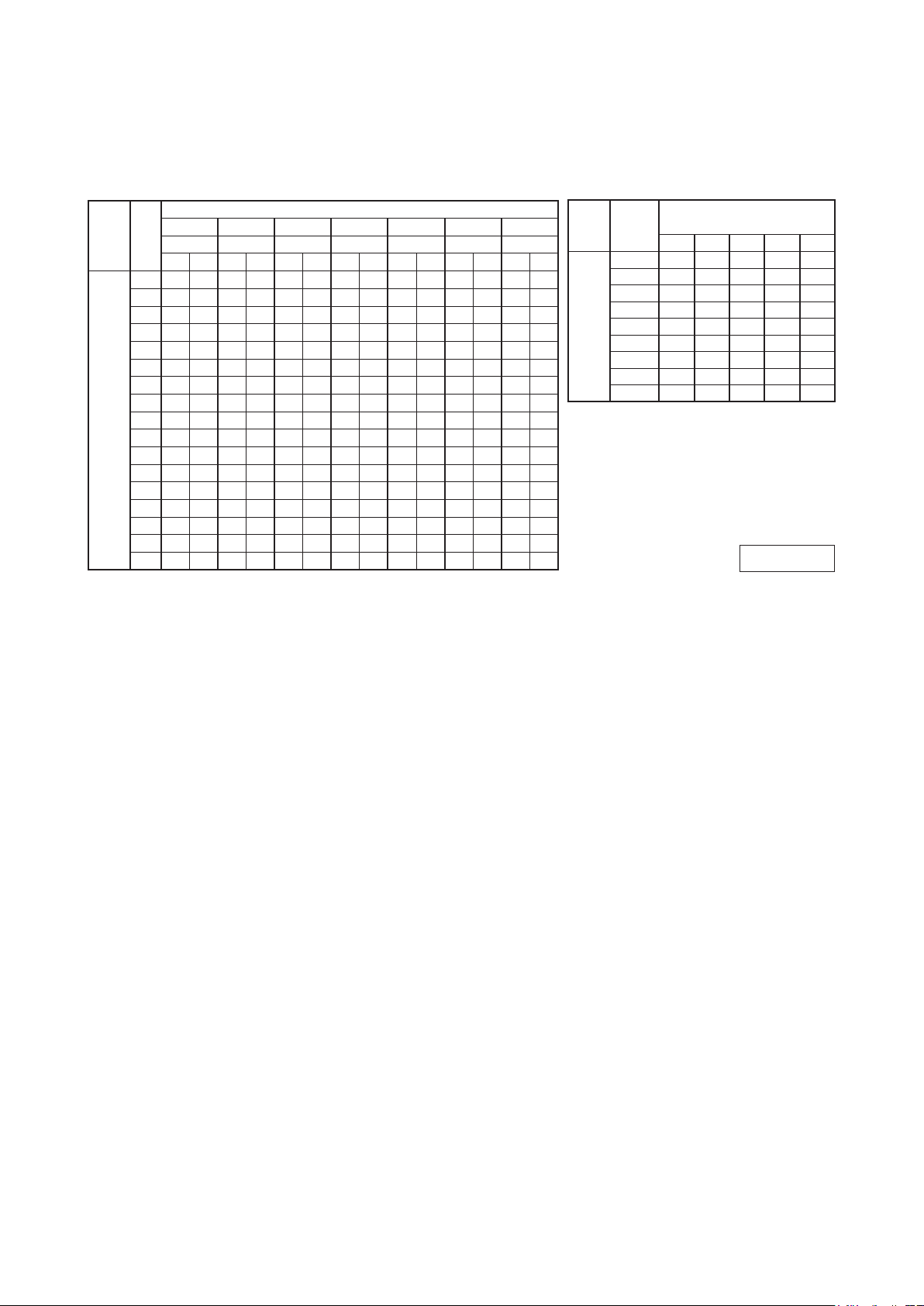
7. CAPACITY TABLE
Model
SRK92ZL-S Cool Mode
Indoor air temp
21℃DB 23℃DB 26℃DB 27℃DB 28℃DB 31℃DB 33℃DB
Outdoor
Air flow
air temp.
14℃WB 16℃WB 18℃WB 19℃WB 20℃WB 22℃WB 24℃WB
TC SHC TC SHC TC SHC TC SHC TC SHC TC SHC TC SHC
10
10.37
7.61
10.85
7.48
11.25
7.67
11.44
7.56
11.64
7.44
11.98
12
10.18
7.51
10.67
7.38
11.09
7.59
11.29
7.48
11.49
7.38
11.85
14 9.99 7.40
16 9.79 7.28
18 9.59 7.18
20 9.38 7.06 9.88 6.98
22 9.16 6.96 9.67 6.87
24 8.94 6.84 9.45 6.77
Hi
21.0
(m3/min)
26 8.72 6.72 9.22 6.65 9.82 6.98
28 8.49 6.59 8.99 6.54 9.62 6.90 9.91 6.86
30 8.25 6.48 8.76 6.42 9.41 6.80 9.71 6.78 9.93 6.71
32 8.01 6.35 8.51 6.31 9.20 6.71 9.51 6.69 9.73 6.62
34 7.77 6.23 8.27 6.19 8.98 6.61 9.31 6.59 9.52 6.53
35 7.64 6.17 8.14 6.13 8.86 6.56 9.20 6.55 9.42 6.49 9.99 6.78
36 7.51 6.11 8.01 6.07 8.75 6.50 9.09 6.51 9.31 6.45 9.89 6.75
38 7.26 5.97 7.75 5.94 8.52 6.41 8.88 6.41 9.09 6.35 9.69 6.68
39 7.12 5.91 7.62 5.88 8.40 6.35 8.77 6.37 8.98 6.31 9.59 6.63
Note (1) These data show average statuses.
Depending on the system control, there may be ranges where the operation is not conducted continuously.
These data show the case where the operation frequency of a compressor is xed.
(2) Capacities are based on the following conditions.
Corresponding refrigerant piping length : 7m.
Level difference of Zero.
(3) Symbols are as follows.
TC:Total cooling capatity
SHC:Sensible heat capacity
HC:Heating capacity
10.48
10.29
10.09
7.28
7.19
7.07
10.93
10.76
10.58
10.40
10.21
10.02
7.51
7.43
7.34
7.26
7.17
7.07
11.13
10.98
10.81
10.64
10.47
10.29
10.10
7.41
7.34
7.26
7.19
7.11
7.01
6.94
11.34
11.18
11.02
10.85
10.68
10.50
10.32
10.13
7.31
7.25
7.17
7.09
7.00
6.93
6.86
6.78
11.72
11.58
11.43
11.28
11.13
10.97
10.80
10.63
10.45
10.27
10.08
7.58
7.52
7.47
7.41
7.36
7.29
7.24
7.17
7.11
7.01
6.95
6.88
6.82
12.30
12.18
12.06
11.93
11.79
11.65
11.50
11.35
11.19
11.03
10.86
10.68
10.50
10.41
10.32
10.12
10.03
(kW)
7.31
7.27
7.23
7.18
7.13
7.07
7.02
6.97
6.89
6.83
6.78
6.72
6.66
6.63
6.60
6.53
6.50
'12 • SRK-T-130
Heat Mode(HC)
Outdoor
Air flow
air temp.
-15℃WB 6.15 6.02 5.88 5.76 5.63
-10℃WB 6.96 6.84 6.75 6.58 6.44
Hi
23.5
(m3/min)
16℃DB 18℃DB 20℃DB 22℃DB 24℃DB
-5℃WB 7.54 7.43 7.28 7.20 7.08
0℃WB 7.91 7.79 7.65 7.56 7.45
5℃WB 10.07 9.95 9.90 9.70 9.57
6℃WB 10.23 10.11 10.00 9.87 9.75
10℃WB 10.87 10.77 10.70 10.56 10.45
15℃WB 11.84 11.73 11.65 11.52 11.41
20℃WB 12.72 12.62 12.56 12.41 12.31
Indoor air temp
(kW)
ISC1 2091
-
18
-
Page 21

BEFORE INSTALLATION
○ Before installation check that the power supply matches the air conditioner.
SELECTION OF INSTALLATION LOCATION
Indoor unit
(Install at location that meets the following conditions, after getting approval from the customer)
○ Where there is no obstructions to the air flow and where the cooled and heated air can be evenly distributed.
○ A solid place where the unit or the wall will not vibrate.
○ A place where there will be enough space for servicing. (Where space mentioned below can be secured)
○ Where wiring and the piping work will be easy to conduct.
○ The place where receiving part is not exposed to the direct rays of the sun or the strong rays of the street lighting.
○ A place where it can be easily drained.
○ A place separated at least 1m away from the television or the radio. (To prevent interference to images and sounds.)
○ Places where this unit is not affected by the high frequency equipment or electric equipment.
○ Avoid installing this unit in place where there is much oil mist.
5 cm mini
mu
m
from the w
all
10
c
m
m
inimum
from the
wa
ll
Installation board
6.5 cm minimum from the ceiling
R410A REFRIGERANT USED
WALL TYPE AIR CONDITIONER
INSTALLATION MANUAL FOR INDOOR UNIT
RKW012A400
1
1
1
Q’ty
Standard accessories (Installation kit)
Accessories for indoor unit
Installation board
(Attached to the rear of the indoor unit)
Wireless remote control
Remote control holder
1
2
3
SAFETY PRECAUTIONS
WARNING
• Read the “SAFETY PRECAUTIONS” carefully first of all and strictly follow it
during the installation work in order to protect yourself.
• The precautionary items mentioned below are distinguished into two levels,
and .
: Wrong installation would cause serious consequences such
as injuries or death.
: Wrong installation might cause serious consequences
depending on circumstances.
Both mentions the important items to protect your health and safety so strictly
follow them by any means.
• Be sure to confirm no anomaly on the equipment by commissioning after com-
pleted installation and explain the operating methods as well as the maintenance
methods of this equipment to the user according to the owner’s manual.
• Keep the installation manual together with owner’s manual at a place where
any user can read at any time. Moreover if necessary, ask to hand them to a
new user.
• For installing qualified personnel, take precautions in respect to themselves by
using suitable protective clothing, groves, etc., and then perform the
installation works.
• Please pay attention not to fall down the tools, etc. when installing the unit at
the high position.
• If unusual noise can be heard during operation, consult the dealer.
• The meanings of “Marks” used here are as shown on the right:
• This installation manual illustrates the method of installing an indoor
unit.
• For electrical wiring work, please see instructions set out on the
backside.
• For outdoor unit installation and refrigerant piping, please refer to the
installation manual that comes with your outdoor unit.
• A wired remote control unit is supplied separately as an optional part.
• When install the unit, be sure to check whether the selection of
installation place, power supply specifications, usage limitation (piping
length, height differences between indoor and outdoor units, power
supply voltage and etc.) and installation spaces.
Never do it under any
circumstances.
Always do it according to the
instruction.
CAUTIONWARNING
CAUTION
WARNING
• Installation must be carried out by the qualified installer.
If you install the system by yourself, it may cause serious trouble such as
water leaks, electric shocks, fire and personal injury, as a result of a
system malfunction.
• Install the system in full accordance with the installation manual.
Incorrect installation may cause bursts, personal injury, water leaks, electric
shocks and fire.
• Be sure to use only for household and residence.
If this appliance is installed in inferior environment such as machine shop
and etc., it can cause malfunction.
• Use the original accessories and the specified components for
installation.
If parts other than those prescribed by us are used, It may cause water
leaks, electric shocks, fire and personal injury.
• Install the unit in a location with good support.
Unsuitable installation locations can cause the unit to fall and cause
material damage and personal injury.
• Ventilate the working area well in the event of refrigerant leakage
during installation.
If the refrigerant comes into contact with naked flames, poisonous gas is
produced.
• When installing in small rooms, take prevention measures not to
exceed the density limit of refrigerant in the event of leakage,
referred by the formula (accordance with ISO5149).
If the density of refrigerant exceeds the limit, please consult the dealer and
install the ventilation system, otherwise lack of oxygen can occur, which
can cause serious accident.
• After completed installation, check that no refrigerant leaks from
the system.
If refrigerant leaks into the room and comes into contact with an oven or
other hot surface, poisonous gas is produced.
• Use the prescribed pipes, flare nuts and tools for R410A.
Using existing parts (for R22 or R407C) can cause the unit failure and
serious accidents due to burst of the refrigerant circuit.
• Tighten the flare nut by torque wrench with specified method.
If the flare nut were tightened with excess torque, this may cause burst and
refrigerant leakage after a long period.
• The electrical installation must be carried out by the qualified
electrician in accordance with “the norm for electrical work” and
“national wiring regulation”, and the system must be connected to
the dedicated circuit.
Power supply with insufficient capacity and incorrect function done by
improper work can cause electric shocks and fire.
• Be sure to shut off the power before starting electrical work.
Failure to shut off the power can cause electric shocks, unit failure or
incorrect function of equipment.
• Be sure to use the cables conformed to safety standard and cable
ampacity for power distribution work.
Unconformable cables can cause electric leak, anomalous heat production
or fire.
• This appliance must be connected to main power supply by means
of a circuit breaker or switch (fuse:20A) with a contact separation of
at least 3mm.
• When plugging this appliance, a plug conforming to the norm
IEC60884-1 must be used.
• Use the prescribed cables for electrical connection, tighten the
cables securely in terminal block and relieve the cables correctly to
prevent overloading the terminal blocks.
Loose connections or cable mountings can cause anomalous heat
production or fire.
• Arrange the wiring in the control box so that it cannot be pushed up
further into the box. Install the service panel correctly.
Incorrect installation may result in overheating and fire.
• Be sure to switch off the power supply in the event of installation,
inspection or servicing.
If the power supply is not shut off, there is a risk of electric shocks, unit
failure or personal injury due to the unexpected start of fan.
CAUTION
• Use the circuit breaker of correct capacity. Circuit breaker should
be the one that disconnect all poles under over current.
Using the incorrect one could cause the system failure and fire.
• Earth leakage breaker must be installed.
If the earth leakage breaker is not installed, it can cause electric shocks.
• Install isolator or disconnect switch on the power supply wiring in
accordance with the local codes and regulations.
• Be sure to install indoor unit properly according to the installation
manual in order to run off the drainage smoothly.
Improper installation of indoor unit can cause dropping water into the room
and damaging personal property.
• Install the drainage pipe to run off drainage securely according to
the installation manual.
Incorrect installation of the drainage pipe can cause dropping water into the
room and damaging personal property.
• Be sure to install the drainage pipe with descending slope of 1/100
or more, and not to make traps and air-bleedings.
Check if the drainage runs off securely during commissioning and ensure
the space for inspection and maintenance.
• Secure a space for installation, inspection and maintenance
specified in the manual.
Insufficient space can result in accident such as personal injury due to
falling from the installation place.
• For installation work, be careful not to get injured with the heat
exchanger, piping flare portion or screws etc.
• Be sure to insulate the refrigerant pipes so as not to condense the
ambient air moisture on them.
Insufficient insulation can cause condensation, which can lead to moisture
damage on the ceiling, floor, furniture and any other valuables.
• When perform the air conditioner operation (cooling or drying
operation) in which ventilator is installed in the room. In this case,
using the air conditioner in parallel with the ventilator, there is the
possibility that drain water may backflow in accordance with the
room lapse into the negative pressure status. Therefore, set up the
opening port such as incorporate the air into the room that may
appropriate to ventilation (For example; Open the door a little). In
addition, just as above, so set up the opening port if the room lapse
into negative pressure status due to register of the wind for the high
rise apartment etc.
• Be sure to perform air tightness test by pressurizing with nitrogen
gas after completed refrigerant piping work.
If the density of refrigerant exceeds the limit in the event of refrigerant
leakage in the small room, lack of oxygen can occur, which can cause
serious accidents.
• Do not install the unit in the locations listed below.
• Locations where carbon fiber, metal powder or any powder is floating.
• Locations where any substances that can affect the unit such as sulphide
gas, chloride gas, acid and alkaline can occur.
• Vehicles and ships.
• Locations where cosmetic or special sprays are often used.
• Locations with direct exposure of oil mist and steam such as kitchen and
machine plant.
• Locations where any machines which generate high frequency harmonics
are used.
• Locations with salty atmospheres such as coastlines.
• Locations with heavy snow (If installed, be sure to provide base flame and
snow hood mentioned in the manual).
• Locations where the unit is exposed to chimney smoke.
• Locations at high altitude (more than 1000m high).
• Locations with ammonic atmospheres.
• Locations where heat radiation from other heat source can affect the unit.
• Locations without good air circulation.
• Locations with any obstacles which can prevent inlet and outlet air of the unit.
• Locations where short circuit of air can occur (in case of multiple units
installation).
• Locations where strong air blows against the air outlet of outdoor unit.
It can cause remarkable decrease in performance, corrosion and damage
of components, malfunction and fire.
• Do not install the indoor unit in the locations listed below (Be sure
to install the indoor unit according to the installation manual for
each model because each indoor unit has each limitation).
• Locations with any obstacles which can prevent inlet and outlet air of the
unit.
• Locations where vibration can be amplified due to insufficient strength of
structure.
• Locations where the infrared receiver is exposed to the direct sunlight or
the strong light beam (in case of the infrared specification unit).
• Locations where an equipment affected by high harmonics is placed (TV
set or radio receiver is placed within 1m).
• Locations where drainage cannot run off safely.
It can affect performance or function and etc.
• Do not install the unit near the location where leakage of
combustible gases can occur.
If leaked gases accumulate around the unit, it can cause fire.
• Do not install the unit where corrosive gas (such as sulfurous acid
gas etc.) or combustible gas (such as thinner and petroleum gases)
can accumulate or collect, or where volatile combustible
substances are handled.
Corrosive gas can cause corrosion of heat exchanger, breakage of plastic
parts and etc. And combustible gas can cause fire.
• Do not use the indoor unit at the place where water splashes may
occur such as in laundries.
Since the indoor unit is not waterproof, it can cause electric shocks and fire.
• Do not install nor use the system close to the equipment that
generates electromagnetic fields or high frequency harmonics.
Equipment such as inverters, standby generators, medical high frequency
equipments and telecommunication equipments can affect the system, and
cause malfunctions and breakdowns. The system can also affect medical
equipment and telecommunication equipment, and obstruct its function or
cause jamming.
• Do not place any variables which will be damaged by getting wet
under the indoor unit.
When the relative humidity is higher than 80% or drainage pipe is clogged,
condensation or drainage water can drop and it can cause the damage of
valuables.
• Do not install the remote control at the direct sunlight.
It can cause malfunction or deformation of the remote control.
• Do not use the unit for special purposes such as storing foods,
cooling precision instruments and preservation of animals, plants or
art.
It can cause the damage of the items.
• Do not use any materials other than a fuse with the correct rating in
the location where fuses are to be used.
Connecting the circuit with copper wire or other metal thread can cause
unit failure and fire.
• Do not touch any buttons with wet hands.
It can cause electric shocks.
• Do not touch any refrigerant pipes with your hands when the
system is in operation.
During operation the refrigerant pipes become extremely hot or extremely
cold depending the operating condition, and it can cause burn injury or
frost injury.
• Carry out the electrical work for ground lead with care.
Do not connect the ground lead to the gas line, water line, lightning conductor or telephone line’s ground lead. Incorrect grounding can cause unit faults
such as electric shocks due to short-circuiting.
• Do not put the drainage pipe directly into drainage channels where
poisonous gases such as sulphide gas can occur.
Poisonous gases will flow into the room through drainage pipe and
seriously affect the user’s health and safety. This can also cause the
corrosion of the indoor unit and a resultant unit failure or refrigerant leak.
• Ensure that no air enters in the refrigerant circuit when the unit is
installed and removed.
If air enters in the refrigerant circuit, the pressure in the refrigerant circuit
becomes too high, which can cause burst and personal injury.
• Do not processing, splice the power cord, or share a socket with
other power plugs.
This may cause fire or electric shock due to defecting contact, defecting
insulation and over-current etc.
• Do not bundling, winding or processing for the power cord. Or, do
not deforming the power plug due to tread it.
This may cause fire or heating.
• Do not vent R410A into the atmosphere : R410A is a fluorinated
greenhouse gas, covered by the Kyoto Protocol with Groval
Warming Potential (GWP)=1975.
• Do not run the unit with removed panels or protections.
Touching rotating equipments, hot surfaces or high voltage parts can cause
personal injury due to entrapment, burn or electric shocks.
• Do not perform any change of protective device itself or its setup
condition.
The forced operation by short-circuiting protective device of pressure
switch and temperature controller or the use of non specified component
can cause fire or burst.
WARNING
'12 • SRK-T-130
Model SRK92ZL-S
8. APPLICATION DATA
(1) Installation of indoor unit
-
-
19
Page 22
'12 • SRK-T-130
Necessary tools for the installation work
1
2
3
4
5
6
7
8
9
10
11
12
13
1
1
1
1
1
1
Q’ty
Option parts
Sealing plate
Sleeve
Inclination plate
Putty
Drain hose (extension hose)
Piping cover
(for insulation of connection piping)
Plus headed driver
Knife
Saw
Tape measure
Hammer
Spanner wrench
Torque wrench
Hole core drill (65mm in diameter)
Wrench key (Hexagon) [4m/m]
Flaring tool set
Gas leak detector
Pipe bender
Gauge for projection adjustment
Used when flare is made by using
conventional flare tool
( )
( )
14.0 ~ 82.0N·m
(1.4 ~ 8.2kgf·m)
(
Designed specifically
for R410A
)
Piping in the left direction
Piping in the right rear directionPiping in the left rear direction
Piping in the right direction
INSTALLATION SPACE (INDOOR UNIT)
(FRONT VIEW)
Piping is possible in the rear, left, left rear, left downward, right or downward direction.
Right
Rear
Downward
Left
rear
Left downward
Left
Wireless remote control
Remote control holder
Wood screws
BEFORE INSTALLATION
○
Before installation check that the power supply matches the air conditioner.
SELECTION OF INSTALLATION LOCATION
INSTALLATION OF INDOOR UNIT
Indoor unit
Relation between setting plate and indoor unit
Installing the support of piping
(Install at location that meets the following conditions, after getting approval from the customer)
○
Where there is no obstructions to the air flow and where the cooled and heated air can be evenly distributed.
○
A solid place where the unit or the wall will not vibrate.
○ A place where there will be enough space for servicing. (Where space mentioned below can be secured)
○ Where wiring and the piping work will be easy to conduct.
○ The place where receiving part is not exposed to the direct rays of the sun or the strong rays of the street lighting.
○ A place where it can be easily drained.
○ A place separated at least 1m away from the television or the radio. (To prevent interference to images and sounds.)
○ Places where this unit is not affected by the high frequency equipment or electric equipment.
○ Avoid installing this unit in place where there is much oil mist.
○ Places where there is no electric equipment or household under the installing unit.
Wireless remote control
In case of piping in the right rear direction
○ A place where the air conditioner can be received the signal surely during operating the wireless remote control.
○ Places where there is no affected by the TV and radio etc.
○
Do not place where exposed to direct sunlight or near heat devices such as a stove.
Sufficient care must be taken not to damage
the panel when connecting pipes.
[Top view]
When drilling the wall that contains a metal lath, wire lath or metal plate, be sure to use pipe hole sleeve sold separately.
• Matters of special notice when piping from left or central/rear of the unit.
Left-hand-side piping Right-hand-side piping
Installation of Installation board
Drilling of holes and fixture of sleeve (Option parts)
Fixing on concrete wall
Use of nut anchor Use of bolt anchor
Shaping of pipings Taping of the exterior
Pipings
Drain hose
Top
Nut
(M6)
Mounting
board
Mounting
board
Max.10
Thickness of the wall + 1.5cm
5
ø65
Indoor side Outdoor sideIndoor side Outdoor side Installed state
Turn to
tighten
b
b
c
a
Bolt
(M6 12)
5 cm mini
mu
m
from the w
all
10
c
m
m
inimum
from the
wa
ll
Installation board
Sleeve (sold separately)
6.5 cm minimum from the ceiling
○ In case of rear piping draw out, cut off the lower
and the right side portions of the sleeve collar.
○ Drill a hole with whole core drill.
○ Hold the bottom of the
piping and fix direction
before stretching it and
shaping it.
○ Tape only the portion
that goes through the
wall.
○ Always tape the wiring
with the piping.
[Drain hose changing procedures]
1. Remove the drain hose 2. Remove the drain cap.
○ Remove it with hand or pliers.○ Remove the screw and drain hose,
making it rotate.
3. Insert the drain cap. 4. Connect the drain hose.
○ Insert the drain cap which was removed
at procedure “2” securely using a
hexagonal wrench etc.
Note: Be careful that If it is not Inserted
securely, water leakage may occur.
○ Insert the drain hose securely, making
rotate. And install the screw.
Note: Be careful that If it is not Inserted
securely, water leakage may
occur.
○ Adjustment of the installation board in the horizontal direction is to
be conducted with eight screws in a temporary tightened state.
○
Adjust so the board will be
level by turning the board
with the standard hole as
the center.
Look for the inside wall structures (Intermediats support or pillar
and firmly install the unit after level surface has been checked.)
CAUTION
Completely seal the hole on
the wall with putty. Otherwise,
furniture, or other, may be
wetted by leaked water or
dewing.
putty
putty
1
1
1
10
2
2
2
Q’ty
Standard accessories (Installation kit)
Accessories for indoor unit
Installation board
(Attached to the rear of the indoor unit)
Wireless remote control
Remote control holder
Battery [R03 (AAA, Micro) 1.5V]
Air-cleaning filters
2
1
Insulation (#486 50 x 100 t3)
Filter holders
(Attached to the front panel of indoor unit)
Tapping screws
(for installation board ø4 X 25mm)
Wood screws
(for remote control switch holder ø3.5 X 16mm)
1
2
3
4
5
6
7
8
9
( )
Designed specifically
for R410A
Indoor side Outdoor side
Standard
hole
610
450
Mating mark for
level surface
(Unit : mm)
Indoor unit
For bolt anchor
and nut anchor
Installation board
Space
for service
100
Space
for service
Piping hole (ø65)
25
50 50
349106
50
44.5
221.5
15 Space
for service
65 Space
for service
7.7 301.8 8.5
44.5
49.5
106
450
886
53.5 77
Piping for Gas 633.5
Piping for Liquid 703.5
Drain hose 772 (ø16)
Piping hole (ø65)
299
-
20
-
Page 23

'12 • SRK-T-130
• Flaring work
Measurement B
Flaring
block
Copper pipe
Finishing work and fixing
Connection wiring,
Earth wiring
Outer tape
Refrigerant piping
Drain hose
Wood screw
Clamp
Cover the exterior portion with outer tape and
shape the piping so it will match the contours
of the route that the piping to take.
Also fix the wiring and pipings to the wall with
clamps.
Open/close and detachment/attachment of the air inlet panel
○ To open, pull the panel at both ends of lower part
and release latches, then pull up the panel until
you feel resistance.
(The panel stops at approx. 60° open position)
○ To close, hold the panel at both ends of lower
part to lower downward and push it slightly until
the latch works.
○ To remove, pull up the panel to the position
shown in right illustration and pull it toward you.
○ To install, insert the panel arm into the slot on the
front panel from the position shown in right
illustration, hold the panel at both ends of lower
part, lower it downward slowly, then push it
slightly until the latch works.
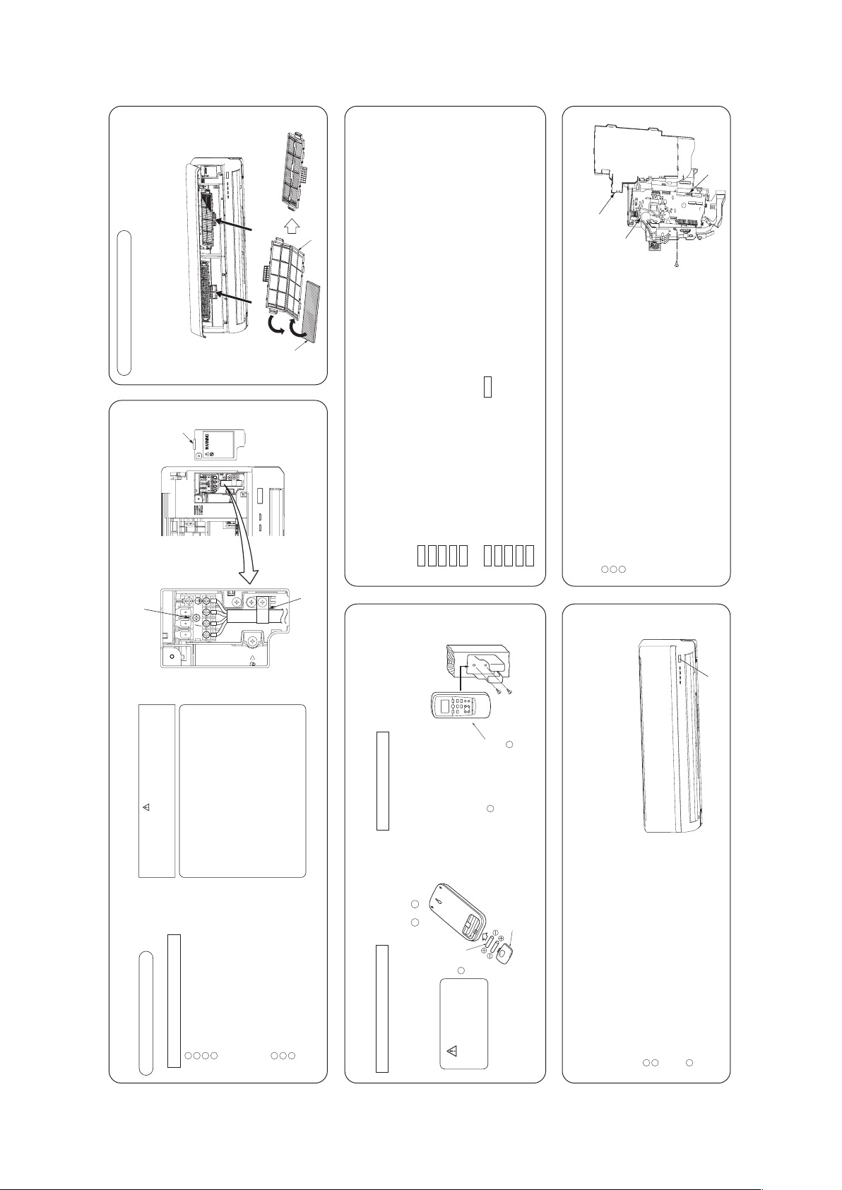
How to remove and install the front panel
Open the air inlet panel.
Remove the lid.
Remove the wiring clamp.
Connect the connecting wire securely to the terminal block.
1) Connect the connection wire securely to the terminal
block. If the wire is not affixed completely, contact will be
poor, and it is dangerous as the terminal block may heat
up and catch fire.
2) Take care not to confuse the terminal numbers for indoor
123
4
ELECTRICAL WIRING WORK
CAUTION
In case of faulty wiring connection, the indoor unit stops, and
then the run lamp turns on and the timer lamp blinks.
Use cables for interconnection wiring to avoid loosening of the
wires.
CENELEC code for cables Required field cables.
H05RNR4G1.5 (example) or 245IEC57
H Harmonized cable type
05 300/500 volts
R Natural-and/or synth, rubber wire insulation
N Polychloroprene rubber conductors insulation
Preparation of indoor unit
Mounting of connecting wires
○ Install the removed flared nuts to the pipes to be connected,
then flared the pipes.
○ Remove the flared nuts. (on both liquid and gas sides)
Keep the openings of the pipes covered with tapes etc. to prevent dust, sand, etc. from entering them.
CONNECTION OF REFRIGERANT PIPINGS
Preparation
(Do not turn)
Press
Remove
A
90 ± 0.5˚
Dimension A
Liquid side ø6.35 : 9.1 (mm)
Gas side ø9.52 : 13.2 (mm)
ø12.7 : 16.6 (mm)
ø15.88 : 19.7 (mm)
CAUTION
Do not apply refrigerating machine
oil to the flared surface.
Indoor
Copper pipe diameter
Use a flare tool designed for R410A or a conventional flare tool.
Please note that measurement B (protrusion from the flaring block) will vary depending on the
type of a flare tool in use.
If a conventional flare tool is used, please use a copper pipe gauge or a similar instrument to
check protrusion so that you can keep measurement B to a correct value.
Clutch type flare tool for
R410A
Conventional (R22) flare tool
ø6.35
ø9.52
ø15.88
0.0 - 0.5
0.0 - 0.5
0.0 - 0.5
1.0 - 1.5
1.0 - 1.5
1.0 - 1.5
1.5 - 2.0
1.5 - 2.0
2.0 - 2.5
ø12.7 0.0 - 0.5 1.0 - 1.5 2.0 - 2.5
Measurement B (mm)
Clutch type Wing nut type
CAUTION
Do not apply excess torque to the flared nuts.
Otherwise, the flared nuts may check depending.
○ Arrange the drain hose in a downward angle.
○ Avoid the following drain piping.
○ Pour water to the drain pan located under the heat exchanger, and ensure that the water is discharged outdoor.
○ When the extended drain hose is indoor, always use a shield pipe (to be arranged by the user) and ensure it is
thermally insulated.
CAUTION
Wall
Gutter
Pipe accommodating section
Since this air conditioner has been designed to collect dew drops on the rear
surface to the drain pan, do not attach the power cord above the gutter.
Drainage
Go through all installation steps and check if the
drainage is all right. Otherwise water leak may occur.
Higher than specified The drain hose
tip is in water.
Wavy The drain hose
tip is in the gutter.
The gap to the ground is
5 cm or less.
Odor from
the gutter
Shield pipe
Drain hose
Extended drain hose
When it is exposed indoor.
2
1
Installation Steps
Pass the pipe through
the hole in the wall,
and hook the upper
part of the indoor unit
to the installation board.
Gently push the lower
part to secure the unit.
• How to remove the indoor unit from the installation board
Fixing of indoor unit
Push up at the marked portion of the indoor unit base lower latch, and slightly
pull it toward you. (both right and left hand sides) (The indoor unit base lower
latch can be removed from the installation board)
Push up the indoor unit upward. So the indoor unit will be removed from the
installation board.
1
2
The marked portion of the indoor unit base lower latch.
Installation board
Indoor unit base latch
Wall
○ Connect the pipes on both liquid and gas sides.
○ Tighten the nuts to the following torque.
Liquid side (ø6.35) : 14.0 - 18.0 N·m (1.4 - 1.8 kgf·m)
Gas side (ø9.52) : 34.0 - 42.0 N·m (3.4 - 4.2 kgf·m)
(ø12.7) : 49.0 - 61.0 N·m (4.9 - 6.1 kgf·m)
(ø15.88) : 68.0 - 82.0 N·m (6.8 - 8.2 kgf·m)
Connection Insulation of the connection portion
Indoor
Liquid side
Gas side
(Do not turn)
• Cover the indoor unit s flare-connected joints, after they are checked for a gas leak,
with an indoor unit heat insulating material and then wrap them with a tape with an
attached insulation pad placed over the heat insulating material’s slit area.
Cover the coupling with insulator and then cover it with tapes.
Vinyl tape
Use an attached insulation pad for heat insulation.
Position it so that the slit area faces upward.
To remove / To install
Installing the air-cleaning filters
1. Open the air inlet panel and remove the air filters.
2. Install the filter holders, with the air-cleaning filters installed in the holders.
In the air conditioner.
• Each air-cleaning filter can be installed in the left or right filter holder.
3. Install the air filters and close the inlet panel.
Installation board
Indoor unit
Latch (2 locations)
○Removing
① Remove the air inlet panel.
② Remove the screw (A) 2pcs / screw
(B) 3pcs fixing to the front panel.
③ Remove the 3 latches in the upper
section of the front panel and then
remove the front panel from the unit.
○Installing
① Remove the air filter.
② Cover the unit with the front panel.
③ Tighten the screw (A) 2pcs / screw
(B) 3pcs to fix the front panel.
④ Install the air filter.
⑤ Install the air inlet panel.
Front panel
Air inlet panel
Air filter
Latch
Screw (A)
Screw (A)
Screw (B)
Screw (B)
Screw (B)
Terminal block
1 3
2 N
Lid
Approx. 80°
-
-
21
Page 24
'12 • SRK-T-130
○ Uncover the wireless remote control, and mount the batteries
[R03 (AAA, Micro), ×2 pieces] in the body regularly.
(Fit the poles with the indication marks, + & − without fail)
○ Conventionally, operate the wireless remote control by holding
in your hand.
○ Avoid installing it on a clay wall etc.
Cover
CAUTION
Wood screws
ø3.5 X 16
Wireless remote control
Battery
INSTALLATION OF WIRELESS CONTROL
Mounting method of battery
Fixing to pillar or wall
Do not use new and
old batteries together.
2
6
5
Open the air inlet panel.
Remove the lid.
Remove the wiring clamp.
Connect the connecting wire securely to the terminal block.
1) Connect the connection wire securely to the terminal
block. If the wire is not affixed completely, contact will be
poor, and it is dangerous as the terminal block may heat
up and catch fire.
2) Take care not to confuse the terminal numbers for indoor
and outdoor connections.
Fix the connecting wire by wiring clamp.
Attach the lid.
Close the air inlet panel.
123
4
567
ELECTRICAL WIRING WORK
CAUTION
In case of faulty wiring connection, the indoor unit stops, and
then the run lamp turns on and the timer lamp blinks.
Use cables for interconnection wiring to avoid loosening of the
wires.
CENELEC code for cables Required field cables.
H05RNR4G1.5 (example) or 245IEC57
H Harmonized cable type
05 300/500 volts
R Natural-and/or synth, rubber wire insulation
N Polychloroprene rubber conductors insulation
R Stranded core
4or5 Number of conductors
G One conductor of the cable is the earth conductor
(yellow/green)
1.5 Section of copper wire (mm
2
)
Preparation of indoor unit
Mounting of connecting wires
• Forced cooling operation
Turn on a power supply again after a while after turn off a power supply.
Then press continually the ON/OFF button 5 seconds or more.
CONCERNING TERMINAL CONNECTION FOR AN INTERFACE
Remove the air inlet panel, lid and front panel.
Remove the control cover. (Remove the screw.)
There is a terminal (respectively marked with CNS) for the indoor control board.
In connecting an interface, connect to the respective terminal securely with the connection harness
supplied with an optional “Interface connection kit SC-BIKN-E ” and fasten the connection harness
onto the indoor control box with the clamp supplied with the kit.
For more details, please refer to the user’s manual of your “Interface connection kit SC-BIKN-E ”.
123
INSTALLATION TEST CHECK POINTS
After installation
The power supply voltage is correct as the rating.
No gas leaks from the joints of the operation valve.
Power cables and crossover wires are securely fixed to the terminal board.
Operation valve is fully open.
The pipe joints for indoor and outdoor pipes have been insulated.
Air conditioning operation is normal.
No abnormal noise.
Water drains smoothly.
Protective functions are not working.
The remote control is normal.
Operation of the unit has been explained to the customer.
(Three-minutes restart preventive timer)
When the air conditioner is restarted or when changing the operation, the unit
will not start operating for approximately 3 minutes.
This is to protect the unit and it is not a malfunction.
Test run
Check the following points again after completion of the installation, and before turning on the power. Conduct a test run again and ensure that the unit operates properly.
At the same time, explain to the customer how to use the unit and how to take care of the unit following the user’s manual.
Filter holder
Air-cleaning
filter
Installing the air-cleaning filters
1. Open the air inlet panel and remove the air filters.
2. Install the filter holders, with the air-cleaning filters installed in the holders.
In the air conditioner.
• Each air-cleaning filter can be installed in the left or right filter holder.
3. Install the air filters and close the inlet panel.
Connect charge hose to check joint of outdoor unit.
Liquid side : Close the liquid valve with hexagon wrench key.
Gas side : Fully open the gas valve.
Carry out cooling operation. (If indoor temperature is low, operate
forced cooling operation.)
After low pressure gauge become 0.01MPa, stop cooling operation
and close the gas valve.
1
2
3
<How to pump down>
○ In order to protect the environment, be sure to pump down (recovery of refrigerant).
○ Pump down is the method of recovering refrigerant from the indoor unit to the
outdoor unit when the pipes are removed from the unit.
HOW TO RELOCATE OR DISPOSE OF THE UNIT
Unit ON/OFF button
Indoor unit PCB
Screw
CNS terminal
Control cover
Terminal block
1 3
2 N
Lid
Wiring Clamp
-
22
-
Page 25

INSTALLATION MANUAL FOR OUTDOOR UNIT
RCR012A101
R410A REFRIGERANT USED
1. HAULAGE AND INSTALLATION (Take particular care in carrying in or moving the unit, and always perform such an operation with two or more persons.)
CAUTION
When a unit is hoisted with slings for haulage, take into consideration the offset of its gravity center position.
If not properly balanced, the unit can be thrown off-balance and fall.
1) Delivery
2) Portage
3) Selecting the installation location
Wooden pallet
• Deliver the unit as close as possible to the installation site before removing it from
the packaging.
• When you have to unpack the unit for a compelling reason before you haul it to
the installation point, hoist the unit with nylon slings or ropes and protection pads
so that you may not damage the unit.
• The right hand side of the unit as viewed from the front (diffuser side) is heavier.
A person carrying the right hand side must take heed of this fact. A person
carrying the left hand side must hold with his right hand the handle provided on
the front panel of the unit and with his left hand the corner column section.
(1) If the unit is installed in the area where the snow will accumulate, following measures are required.
The bottom plate of unit and intake, outlet may be blocked by snow.
1 Install the unit on the base so that the bottom is
higher than snow cover surface.
Since drain water generated by defrost control may freeze, following measures are required.
• Do not execute drain piping work by using a drain elbow and drain grommets (optional parts).
[Refer to Drain piping work.]
2 Install the unit under eaves or provide the roof
on site.
Be careful of the following conditions and choose an installation place.
• Where air is not trapped.
• Where the installation fittings can be firmly installed.
• Where wind does not hinder the intake and outlet pipes.
• Out of the heat range of other heat sources.
• A place where stringent regulation of electric noises is applicable.
• Where it is safe for the drain water to be discharged.
• Where noise and hot air will not bother neighboring residents.
• Where snow will not accumulate.
• Where strong winds will not blow against the outlet pipe.
• A place where no TV set or radio receiver is placed within 1m.
(If electrical interference is caused, seek a place less likely to cause the problem)
• If a operation is conducted when the outdoor air temperature is –5°C lower, the outdoor unit should be
installed at a place where it is not influenced by natural wind.
• Where it is likely that the unit is subjected to strong winds, provide wind guards according to the
following guidelines. Strong winds can cause performance degradation, an accidental stop due to a rise of
high pressure and a broken fan.
4) Caution about selection of installation location
Notabilia as a unit designed for R410A
• Do not use any refrigerant other than R410A. R410A will rise to pressure about 1.6 times higher than that of a conventional refrigerant.
A cylinder containing R410A has a pink indication mark on the top.
• A unit designed for R410A has adopted a different size indoor unit operation valve charge port and a different size check joint provided in the unit to prevent the charging of a wrong refrigerant by mistake.
The processed dimension of the flared part of a refrigerant pipe and a flare nut’s parallel side measurement have also been altered to raise strength against pressure.
Accordingly, you are required to arrange dedicated R410A tools listed in the table on the left before installing or servicing this unit.
• Do not use a charge cylinder. The use of a charge cylinder will cause the refrigerant composition to change, which results in performance degradation.
• In charging refrigerant, always take it out from a cylinder in the liquid phase.
• All indoor units must be models designed exclusively for R410A. Check connectable indoor unit models in a catalog, etc. (A wrong indoor unit, if connected into the system, will impair proper system operation)
• Read the “SAFETY PRECAUTIONS” carefully first of all and strictly follow it during the installation work in order
to protect yourself.
• The precautionary items mentioned below are distinguished into two levels, and .
: Wrong installation would cause serious consequences such as injuries or death.
: Wrong installation might cause serious consequences depending on circumstances.
Both mentions the important items to protect your health and safety so strictly follow them by any means.
• Be sure to confirm no anomaly on the equipment by commissioning after completed installation and explain the
operating methods as well as the maintenance methods of this equipment to the user according to the owner’s
manual.
• Keep the installation manual together with owner’s manual at a place where any user can read at any time.
Moreover if necessary, ask to hand them to a new user.
• For installing qualified personnel, take precautions in respect to themselves by using suitable protective
clothing, groves, etc., and then perform the installation works.
• Please pay attention not to fall down the tools, etc. when installing the unit at the high position.
• If unusual noise can be heard during operation, consult the dealer.
• The meanings of “Marks” used here are shown as follows:
• This installation manual deals with outdoor units and general installation specifications only. For indoor units, refer to the respective installation manuals supplied with the units.
• When install the unit, be sure to check whether the selection of installation place, power supply specifications, usage limitation (piping length, height differences between indoor and outdoor units, power
supply voltage and etc.) and installation spaces.
SAFETY PRECAUTIONS
WARNING
Never do it under any circumstances. Always do it according to the instruction.
CAUTIONWARNING
CAUTION
WARNING
CAUTION
• Carry out the electrical work for ground lead with care.
Do not connect the ground lead to the gas line, water line, lightning conductor or telephone line’s ground lead. Incorrect grounding can cause unit faults such as electric shocks due to short-circuiting.
• Installation must be carried out by the qualified installer.
If you install the system by yourself, it may cause serious trouble such as water leaks,
electric shocks, fire and personal injury, as a result of a system malfunction. Do not
carry out the installation and maintenance work except the by qualified installer.
• Install the system in full accordance with the installation manual.
Incorrect installation may cause bursts, personal injury, water leaks, electric
shocks and fire.
• Be sure to use only for household and residence.
If this appliance is installed in inferior environment such as machine shop and etc.,
it can cause malfunction.
• When installing in small rooms, take prevention measures not to
exceed the density limit of refrigerant in the event of leakage, referred
by the formula (accordance with ISO5149).
If the density of refrigerant exceeds the limit, please consult the dealer and install
the ventilation system, otherwise lack of oxygen can occur, which can cause serious
accident.
• Use the original accessories and the specified components for
installation.
If parts other than those prescribed by us are used, It may cause water leaks,
electric shocks, fire and personal injury.
• Install the unit in a location with good support.
Unsuitable installation locations can cause the unit to fall and cause material
damage and personal injury.
• Ensure the unit is stable when installed, so that it can withstand
earthquakes and strong winds.
Unsuitable installation locations can cause the unit to fall and cause material
damage and personal injury.
• Ventilate the working area well in the event of refrigerant leakage during
installation.
If the refrigerant comes into contact with naked flames, poisonous gas is produced.
• Use the prescribed pipes, flare nuts and tools for R410A.
Using existing parts (for R22 or R407C) can cause the unit failure and serious
accidents due to burst of the refrigerant circuit.
• Tighten the flare nut by torque wrench with specified method.
If the flare nut were tightened with excess torque, this may cause burst and
refrigerant leakage after a long period.
• Do not open the operation valves for liquid line and gas line until
completed refrigerant piping work, air tightness test and evacuation.
If the compressor is operated in state of opening operation valves before
completed connection of refrigerant piping work, air can be sucked into refrigeran t
circuit, which can cause bust or personal injur y due to anomalously high pressure
in the refrigerant.
• The electrical installation must be carried out by the qualified electrician
in accordance with “the norm for electrical work” and “national wiring
regulation”, and the system must be connected to the dedicated circuit.
Power supply with insufficient capacity and incorrect function done by improper
work can cause electric shocks and fire.
• Be sure to shut off the power before starting electrical work.
Failure to shut off the power can cause electric shocks, unit failure or incorrect
function of equipment.
• Be sure to use the cables conformed to safety standard and cable
ampacity for power distribution work.
Unconformable cables can cause electric leak, anomalous heat production or fire.
• This appliance must be connected to main power supply by means of a
circuit breaker or switch (fuse:20A) with a contact separation of at least
3mm.
• Arrange the wiring in the control box so that it cannot be pushed up
further into the box. Install the service panel correctly.
Incorrect installation may result in overheating and fire.
• Use the prescribed cables for electrical connection, tighten the cables
securely in terminal block and relieve the cables correctly to prevent
overloading the terminal blocks.
Loose connections or cable mountings can cause anomalous heat production or fire.
• Be sure to fix up the service panels.
Incorrect fixing can cause electric shocks or fire due to intrusion of dust or water.
• Be sure to switch off the power supply in the event of installation,
inspection or servicing.
If the power supply is not shut off, there is a risk of electric shocks, unit failure or
personal injury due to the unexpected start of fan.
• Stop the compressor before removing the pipe after shutting the
service valve on pump down work.
If the pipe is removed when the compressor is in operation with the service valve
open, air would be mixed in the refrigeration circuit and it could cause explosion
and injuries due to abnormal high pressure in the cooling cycle.
• Only use prescribed optional parts. The installation must be carried out
by the qualified installer.
If you install the system by yourself, it can cause serious trouble such as water
leaks, electric shocks, fire.
• Be sure to wear protective goggles and gloves while at work.
• Earth leakage breaker must be installed.
If the earth leakage breaker is not installed, it can cause electric shocks.
• Ensure that no air enters in the refrigerant circuit when the unit is
installed and removed.
If air enters in the refrigerant circuit, the pressure in the refrigerant circuit
becomes too high, which can cause burst and personal injury.
•
Do not processing, splice the power cord, or share a socketwithother power plugs.
This may cause fire or electric shock due to defecting contact, defecting insulation
and over-current etc.
• Do not bundling, winding or processing for the power cord. Or, do not
deforming the power plug due to tread it.
This may cause fire or heating.
• Do not run the unit with removed panels or protections.
Touching rotating equipments, hot surfaces or high voltage parts can cause
personal injury due to entrapment, burn or electric shocks.
• Do not perform any change of protective device itself or its setup
condition.
The forced operation by short-circuiting protective device of pressure switch and
temperature controller or the use of non specified component can cause fire or
burst.
• Use the circuit breaker for all pole correct capacity. Circuit breaker
should be the one that disconnect all poles under over current.
Using the incorrect circuit breaker, it can cause the unit malfunction and fire.
• Install isolator or disconnect switch on the power supply wiring in
accordance with the local codes and regulations.
The isolator should be locked in OFF state in accordance with EN60204-1.
• After maintenance, all wiring, wiring ties and the like,shouldbe returned
to their original state and wiring route, and the necessary clearance from
all metal parts should be secured.
• Secure a space for installation, inspection and maintenance specified in
the manual.
Insufficient space can result in accident such as personal injury due to falling from
the installation place.
• Take care when carrying the unit by hand.
If the unit weights more than 20kg, it must be carried by two or more persons. Do
not carry by the plastic straps, always use the carry handle when carrying the unit
by hand. Use gloves to minimize the risk of cuts by the aluminum fins.
• Dispose of any packing materials correctly.
Any remaining packing materials can cause personal injury as it contains nails and
wood. And to avoid danger of suffocation, be sure to keep the plastic wrapper
away from children and to dispose after tear it up.
• Be sure to insulate the refrigerant pipes so as not to condense the
ambient air moisture on them.
Insufficient insulation can cause condensation, which can lead to moisture
damage on the ceiling, floor, furniture and any other valuables.
• When perform the air conditioner operation (cooling or drying operation)
in which ventilator is installed in the room. In this case, using the air
conditioner in parallel with the ventilator, there is the possibility that
drain water may backflow in accordance with the room lapse into the
negative pressure status. Therefore, set up the opening port such as
incorporate the air into the room that may appropriate to ventilation (For
example; Open the door a little). In addition, just as above, so set up the
opening port if the room lapse into negative pressure status due to
register of the wind for the high rise apartment etc.
• Do not install the unit in the locations listed below.
•Locations where carbon fiber, metal powder or any powder is floating.
•Locations where any substances that can affect the unit such as sulphide gas,
chloride gas, acid and alkaline can occur.
•Vehicles and ships.
•Locations where cosmetic or special sprays are often used.
• Do not install the outdoor unit in the locations listed below.
• Locations where discharged hot air or operating sound of the outdoor unit can
bother neighborhood.
• Locations where outlet air of the outdoor unit blows directly to an animal or
plants. The outlet air can affect adversely to the plant etc.
• Locations where vibration can be amplified and transmitted due to insufficient
•Do not install the outdoor unit in a location where insects and small
animals can inhabit.
Insects and small animals can enter the electric parts and cause damage or fire.
Instruct the user to keep the surroundings clean .
•Do not use the base flame for outdoor unit which is corroded or damaged
due to long periods of operation.
'12 • SRK-T-130
Model SRC92ZL-S
(2) Installation of outdoor unit
-
-
23
Page 26
Accessories for outdoor unit
• Model name and power source
• Refrigerant piping length
• Piping, wiring and miscellaneous small parts
• Indoor unit installation manual
Necessary tools for the installation work
Wrench key (Hexagon) [4m/m]
Vacuum pump
Vacuum pump adapter (Anti-reverse flow type)
(Designed specifically for R410A)
Gauge manifold (Designed specifically for R410A)
Charge hose (Designed specifically for R410A)
Flaring tool set (Designed specifically for R410A)
Gas leak detector (Designed specifically for R410A)
Gauge for projection adjustment
(Used when flare is made by using conventional flare tool)
9
10
1112131415
16
Plus headed driver
Knife
Saw
Tape measure
Hammer
Spanner wrench
Torque wrench [14.0
~
82.0N·m (1.4
~
8.2kgf·m)]
Hole core drill (65mm in diameter)
1234567
8
Grommet (Heat pump type only)
Drain elbow (Heat pump type only)
Edging
Q’ty
211
123
Option parts
Sealing plate
Sleeve
Inclination plate
Putty
Drain hose (extension hose)
Piping cover
(for insulation of connection piping)
Q’ty
11111
1
abcde
f
The bottom plate of unit and intake, outlet may be blocked by snow.
1 Install the unit on the base so that the bottom is
higher than snow cover surface.
Since drain water generated by defrost control may freeze, following measures are required.
• Do not execute drain piping work by using a drain elbow and drain grommets (optional parts).
[Refer to Drain piping work.]
Determine refrigerant pipe size pursuant to the following guidelines based
on the indoor unit specifications.
Without nitrogen gas, a large quantity of foreign matters
(oxidized film) are created, causing a critical failure from
capillary tube or expansion valve clogging.
2 Install the unit under eaves or provide the roof
on site.
2. REFRIGERANT PIPING WORK
1) Restrictions on unit installation and use
2) Determination of pipe size
The use restrictions appearing in the table above are applicable to the standard pipe size combinations shown in the table below.
Restrictions
Marks appearing in the
drawing on the right
Main pipe length
When the outdoor unit is positioned higher,
When the outdoor unit is positioned lower,
Elevation difference between
indoor and outdoor units
Brazing must be performed under a nitrogen gas flow.
About brazing
When pipe is brazing.
• Check the following points in light of the indoor unit specifications and the installation site.
• Observe the following restrictions on unit installation and use. Improper installation can result in a compressor failure or performance degradation.
30m or less
20m or less
20m or less
Dimensional restrictions
ø15.88
Flare
ø15.88
ø15.88
Gas pipe
ø6.35
Flare
ø6.35
ø6.35
Liquid pipe
Outdoor unit connected
Refrigerant piping (branch pipe L)
Indoor unit connected
CAUTION
Check before installation work
CAUTION
• Carry out the electrical work for ground lead with care.
Do not connect the ground lead to the gas line, water line, lightning conductor or telephone line’s ground lead. Incorrect grounding can cause unit faults such as electric shocks due to short-circuiting.
• Use the circuit breaker for all pole correct capacity. Circuit breaker
should be the one that disconnect all poles under over current.
Using the incorrect circuit breaker, it can cause the unit malfunction and fire.
• Install isolator or disconnect switch on the power supply wiring in
accordance with the local codes and regulations.
The isolator should be locked in OFF state in accordance with EN60204-1.
• After maintenance, all wiring, wiring ties and the like, should be returned
to their original state and wiring route, and the necessary clearance from
all metal parts should be secured.
• Secure a space for installation, inspection and maintenance specified in
the manual.
Insufficient space can result in accident such as personal injury due to falling from
the installation place.
• Take care when carrying the unit by hand.
If the unit weights more than 20kg, it must be carried by two or more persons. Do
not carry by the plastic straps, always use the carry handle when carrying the unit
by hand. Use gloves to minimize the risk of cuts by the aluminum fins.
• Dispose of any packing materials correctly.
Any remaining packing materials can cause personal injury as it contains nails and
wood. And to avoid danger of suffocation, be sure to keep the plastic wrapper
away from children and to dispose after tear it up.
• Be sure to insulate the refrigerant pipes so as not to condense the
ambient air moisture on them.
Insufficient insulation can cause condensation, which can lead to moisture
damage on the ceiling, floor, furniture and any other valuables.
• When perform the air conditioner operation (cooling or drying operation)
in which ventilator is installed in the room. In this case, using the air
conditioner in parallel with the ventilator, there is the possibility that
drain water may backflow in accordance with the room lapse into the
negative pressure status. Therefore, set up the opening port such as
incorporate the air into the room that may appropriate to ventilation (For
example; Open the door a little). In addition, just as above, so set up the
opening port if the room lapse into negative pressure status due to
register of the wind for the high rise apartment etc.
• Do not install the unit in the locations listed below.
•Locations where carbon fiber,meta l powder or any powder is floating.
•Locations where any substances that can affect the unit such as sulphide gas,
chloride gas, acid and alkaline can occur.
•Vehicles and ships.
•Locations where cosmetic or special sprays are often used.
•Locations with direct exposure of oil mist and steam such as kitchen and
machine plant.
•Locations where any machines which generate high frequency harmonics are
used.
•Locations with salty atmospheres such as coastlines.
•Locations with heavy snow (If installed, be sure to provide base flame and snow
hood mentioned in the manual).
•Locations where the unit is exposed to chimney smoke.
•Locations at high altitude (more than 1000m high).
•Locations with ammonic atmospheres.
•Locations where heat radiation from other heat source can affect the unit.
•Locations without good air circulation.
•Locations with any obstacles which can prevent inlet and outlet air of the unit.
•Locations where short circuit of air can occur (in case of multiple units
installation).
•Locations where strong air blows against the air outlet of outdoor unit.
•Locations where something located above the unit could fall.
It can cause remarkable decrease in performance, corrosion and damage of
components, malfunction and fire.
• Do not install the outdoor unit in the locations listed below.
• Locations where discharged hot air or operating sound of the outdoor unit can
bother neighborhood.
• Locations where outlet air of the outdoor unit blows directly to an animal or
plants. The outlet air can affect adversely to the plant etc.
• Locations where vibration can be amplified and transmitted due to insufficient
strength of structure.
• Locations where vibration and opera tion sound generated by the outdoor unit
can affect seriously (on the wall or at the place near bed room).
• Locations where an equipment affected by high harmonics is placed (TV set or
radio receiver is placed within 1m).
• Locations where drainage cannot run off safely.
It can affect surrounding environment and cause a claim.
• Do not install the unit near th e location where leakage of combustible
gases can occur.
If leaked gases accumulate around the unit, it can cause fire.
• Do not install the unit wherecorrosive gas (suchas sulfurousacid gas etc.)
or combustible gas (suchas thinner and petroleum gases) can accumulate
or collect, or where volatile combustible substances are handled.
Corrosive gas can cause corrosion of heat exchanger, breakage of plastic parts
and etc. And combustibl e gas ca n cause fire.
• Do not install nor use the syst e m close to the equipment that generates
electromagnetic fields or high frequency harmonics.
Equipment such as inverters, standby generators, medical high frequency
equipments and telecommunication equipments can affect the system, and cause
malfunctions and breakdowns. The system can also affect medical equipment and
telecommunication equipment, and obstruct its function or cause jamming.
•Do not install the outdoor unit in a location where insects and small
animals can inhabit.
Insects and small animals can enter the electric parts and cause damage or fire.
Instruct the user to keep the surroundings clean.
•Do not use the base flame for outdoor unit which is corroded or damaged
due to long periods of operation.
Using an old and damage base flame can cause the unit f a l l i n g down and cause
personal injury.
•Do not use any materials other than a fuse with the correct rating in the
location where fuses are to be used.
Connecting the circuit with copper wire or other metal thread can cause unit
failure and fire.
•Do not touch any buttons with w e t hands.
It can cause electric shocks.
•Do not touch any refrigerant pipes with your hands when the system is in
operation.
During operation the refrigerant pipes become extremely hot or extremely cold
depending the operating condition, and it can cause burn injury or frost injury.
•Do not touch the suction or alu m i n u m fin on the outdoor unit.
This may cause injury.
•Do not put anything on the outd o o r unit and operating unit.
This may cause damage the objects or injury due to falling to the object.
•Do not use the unit for special purposes such as storing foods, cooling
precision instruments and preservation of animals, plants or art.
•Do not clean up the unit with water.
1. HAULAGE AND INSTALLATION (Take particular care in carrying in or moving the unit, and always perform such an operation with two or more persons.)
Intake
The height of a wall is 1200mm or less.
(
service
space
)
Intake
Outlet
Fasten with bolts
(M10-12)
Use a thicker block to anchor deeper.Use a long block to extend the width.
CAUTION
When a unit is hoisted with slings for haulage, take into consideration the offset of its gravity center position.
If not properly balanced, the unit can be thrown off-balance and fall.
1) Delivery
2) Portage
3) Selecting the installation location
5) Installation space
L3
L2
L4
L1
Example installation
Size
L1L2L3
L4
Open
300
100
250
Open
250
150
250
500
Open
100
250
(mm)
I II III
Heavy
6) Installation
Pad
Wooden pallet
Over 500mm
• Deliver the unit as close as possible to the installation site before removing it from
the packaging.
• When you have to unpack the unit for a compelling reason before you haul it to
the installation point, hoist the unit with nylon slings or ropes and protection pads
so that you may not damage the unit.
• The right hand side of the unit as viewed from the front (diffuser side) is heavier.
A person carrying the right hand side must take heed of this fact. A person
carrying the left hand side must hold with his right hand the handle provided on
the front panel of the unit and with his left hand the corner column section.
(1) If the unit is installed in the area where the snow will accumulate, following measures are required.
The bottom plate of unit and intake, outlet may be blocked by snow.
1 Install the unit on the base so that the bottom is
higher than snow cover surface.
Since drain water generated by defrost control may freeze, following measures are required.
• Do not execute drain piping work by using a drain elbow and drain grommets (optional parts).
[Refer to Drain piping work.]
2 Install the unit under eaves or provide the roof
on site.
Be careful of the following conditions and choose an installation place.
• Where air is not trapped.
• Where the installation fittings can be firmly installed.
• Where wind does not hinder the intake and outlet pipes.
• Out of the heat range of other heat sources.
• A place where stringent regulation of electric noises is applicable.
• Where it is safe for the drain water to be discharged.
• Where noise and hot air will not bother neighboring residents.
• Where snow will not accumulate.
• Where strong winds will not blow against the outlet pipe.
• A place where no TV set or radio receiver is placed within 1m.
(If electrical interference is caused, seek a place less likely to cause the problem)
• If a operation is conducted when the outdoor air temperature is –5°C lower, the outdoor unit should be
installed at a place where it is not influenced by natural wind.
• Where it is likely that the unit is subjected to strong winds, provide wind guards according to the
following guidelines. Strong winds can cause performance degradation, an accidental stop due to a rise of
high pressure and a broken fan.
2. REFRIGERANT PIPING WORK
4) Caution about selection of installation location
• Walls surrounding the unit in the four sides are not
acceptable.
• There must be a 1-meter or larger space in the above.
• When more than one unit are installed side by side,
provide a 250mm or wider interval between them as a
service space. In order to facilitate servicing of
controllers, please provide a sufficient space between
units so that their top plates can be removed easily.
• Where a danger of short-circuiting exists, install guide
louvers.
• When more than one unit are installed, provide sufficient
intake space consciously so that short-circuiting may not
occur.
• Where piling snow can bury the outdoor unit, provide
proper snow guards.
• In installing the unit, fix the unit’s legs with bolts specified on the above.
• The protrusion of an anchor bolt on the front side must be kept within 15mm.
• Securely install the unit so that it does not fall over during earthquakes or strong winds, etc.
• Refer to the above illustrations for information regarding concrete foundations.
• Install the unit in a level area. (With a gradient of 5mm or less.) Improper installation can result in a
compressor failure, broken piping within the unit and abnormal noise generation.
1 Anchor bolt fixed position
2 Notabilia for installation
(2) If the unit can be affected by strong wind, following measures are required.
Strong wind can cause damage of fan (fan motor), or can cause performance degradation, or can trigger
anomalous stop of the unit due to rising of high pressure.
1 Place the unit outlet side is turned to the wall. 2 Install so the direction of the air from the
blowing outlet will be perpendicular to the
direction of the wind.
Wind
direction
Wind
direction
Notabilia as a unit designed for R410A
• Do not use any refrigerant other than R410A. R410A will rise to pressure about 1.6 times higher than that of a conventional refrigerant.
A cylinder containing R410A has a pink indication mark on the top.
• A unit designed for R410A has adopted a different size indoor unit operation valve charge port and a different size check joint provided in the unit to prevent the charging of a wrong refrigerant by mistake.
The processed dimension of the flared part of a refrigerant pipe and a flare nut’s parallel side measurement have also been altered to raise strength against pressure.
Accordingly, you are required to arrange dedicated R410A tools listed in the table on the left before installing or servicing this unit.
• Do not use a charge cylinder. The use of a charge cylinder will cause the refrigerant composition to change, which results in performance degradation.
• In charging refrigerant, always take it out from a cylinder in the liquid phase.
• All indoor units must be models designed exclusively for R410A. Check connectable indoor unit models in a catalog, etc. (A wrong indoor unit, if connected into the system, will impair proper system operation)
190 200580
20
410
20
Intake
Outlet
'12 • SRK-T-130
-
-
24
Page 27
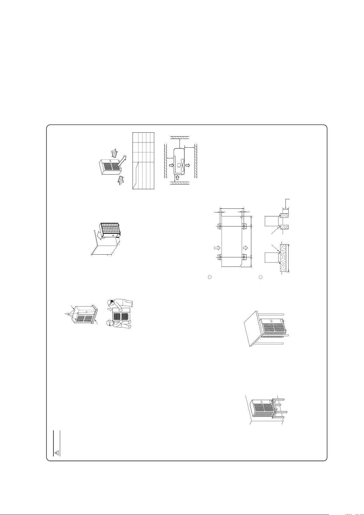
'12 • SRK-T-130
1. HAULAGE AND INSTALLATION (Take particular care in carrying in or moving the unit, and always perform such an operation with two or more persons.)
Intake
The height of a wall is 1200mm or less.
(
service
space
)
Intake
Outlet
Fasten with bolts
(M10-12)
Use a thicker block to anchor deeper.Use a long block to extend the width.
CAUTION
When a unit is hoisted with slings for haulage, take into consideration the offset of its gravity center position.
If not properly balanced, the unit can be thrown off-balance and fall.
1) Delivery
2) Portage
3) Selecting the installation location
5) Installation space
L3
L2
L4
L1
Example installation
Size
L1L2L3
L4
Open
300
100
250
Open
250
150
250
500
Open
100
250
(mm)
I II III
Heavy
6) Installation
Pad
Wooden pallet
Over 500mm
• Deliver the unit as close as possible to the installation site before removing it from
the packaging.
• When you have to unpack the unit for a compelling reason before you haul it to
the installation point, hoist the unit with nylon slings or ropes and protection pads
so that you may not damage the unit.
• The right hand side of the unit as viewed from the front (diffuser side) is heavier.
A person carrying the right hand side must take heed of this fact. A person
carrying the left hand side must hold with his right hand the handle provided on
the front panel of the unit and with his left hand the corner column section.
(1) If the unit is installed in the area where the snow will accumulate, following measures are required.
The bottom plate of unit and intake, outlet may be blocked by snow.
1 Install the unit on the base so that the bottom is
higher than snow cover surface.
Since drain water generated by defrost control may freeze, following measures are required.
• Do not execute drain piping work by using a drain elbow and drain grommets (optional parts).
[Refer to Drain piping work.]
2 Install the unit under eaves or provide the roof
on site.
Be careful of the following conditions and choose an installation place.
• Where air is not trapped.
• Where the installation fittings can be firmly installed.
• Where wind does not hinder the intake and outlet pipes.
• Out of the heat range of other heat sources.
• A place where stringent regulation of electric noises is applicable.
• Where it is safe for the drain water to be discharged.
• Where noise and hot air will not bother neighboring residents.
• Where snow will not accumulate.
• Where strong winds will not blow against the outlet pipe.
• A place where no TV set or radio receiver is placed within 1m.
(If electrical interference is caused, seek a place less likely to cause the problem)
• If a operation is conducted when the outdoor air temperature is –5°C lower, the outdoor unit should be
installed at a place where it is not influenced by natural wind.
• Where it is likely that the unit is subjected to strong winds, provide wind guards according to the
following guidelines. Strong winds can cause performance degradation, an accidental stop due to a rise of
high pressure and a broken fan.
2. REFRIGERANT PIPING WORK
1) Restrictions on unit installation and use
L
H
H
L
H
Indoor unit
Restrictions
Marks appearing in the
drawing on the right
Main pipe length
When the outdoor unit is positioned higher,
When the outdoor unit is positioned lower,
Elevation difference between
indoor and outdoor units
4) Caution about selection of installation location
• Walls surrounding the unit in the four sides are not
acceptable.
• There must be a 1-meter or larger space in the above.
• When more than one unit are installed side by side,
provide a 250mm or wider interval between them as a
service space. In order to facilitate servicing of
controllers, please provide a sufficient space between
units so that their top plates can be removed easily.
• Where a danger of short-circuiting exists, install guide
louvers.
• When more than one unit are installed, provide sufficient
intake space consciously so that short-circuiting may not
occur.
• Where piling snow can bury the outdoor unit, provide
proper snow guards.
• In installing the unit, fix the unit’s legs with bolts specified on the above.
• The protrusion of an anchor bolt on the front side must be kept within 15mm.
• Securely install the unit so that it does not fall over during earthquakes or strong winds, etc.
• Refer to the above illustrations for information regarding concrete foundations.
• Install the unit in a level area. (With a gradient of 5mm or less.) Improper installation can result in a
compressor failure, broken piping within the unit and abnormal noise generation.
1 Anchor bolt fixed position
2 Notabilia for installation
(2) If the unit can be affected by strong wind, following measures are required.
Strong wind can cause damage of fan (fan motor), or can cause performance degradation, or can trigger
anomalous stop of the unit due to rising of high pressure.
1 Place the unit outlet side is turned to the wall. 2 Install so the direction of the air from the
blowing outlet will be perpendicular to the
direction of the wind.
Wind
direction
Wind
direction
• Check the following points in light of the indoor unit specifications and the installation site.
• Observe the following restrictions on unit installation and use. Improper installation can result in a compressor failure or performance degradation.
30m or less
20m or less
20m or less
Dimensional restrictions
190 200580
20
410
20
Intake
Outlet
-
25
-
Page 28

Determine refrigerant pipe size pursuant to the following guidelines based
on the indoor unit specifications.
Without nitrogen gas, a large quantity of foreign matters
(oxidized film) are created, causing a critical failure from
capillary tube or expansion valve clogging.
2. REFRIGERANT PIPING WORK
1) Restrictions on unit installation and use
2) Determination of pipe size
L
H
H
L
H
Outdoor unit
Indoor unit
The use restrictions appearing in the table above are applicable to the standard pipe size combinations shown in the table below.
Restrictions
Marks appearing in the
drawing on the right
Main pipe length
When the outdoor unit is positioned higher,
When the outdoor unit is positioned lower,
Elevation difference between
indoor and outdoor units
Plug the end of the pipe with tape, orother
material, and fill the pipe with nitrogen gas.
Only use nitrogen gas (N2)
Taping
<N2>
Nitrogen
Brazing
Station valve
Primary side Secondary side
0.5MPa
Hand
Relief valve
Nitrogen
gas
Brazing must be performed under a nitrogen gas flow.
About brazing
When pipe is brazing.
• Check the following points in light of the indoor unit specifications and the installation site.
• Observe the following restrictions on unit installation and use. Improper installation can result in a compressor failure or performance degradation.
30m or less
20m or less
20m or less
Dimensional restrictions
ø15.88
Flare
ø15.88
ø15.88
Gas pipe
ø6.35
Flare
ø6.35
ø6.35
Liquid pipe
Outdoor unit connected
Refrigerant piping (branch pipe L)
Indoor unit connected
CAUTION
Take care so that installed pipes may not touch components within a unit.
If touching with an internal component, it will generate abnormal sounds and/or vibrations.
4) On-site piping work
IMPORTANT
How to remove the service panel
First remove the five screws ( mark) of the service panel and push it down into
the direction of the arrow mark and then remove it by pulling it toward you.
CAUTION
Do not apply force beyond proper fastening torque in tightening the flare nut.
Tightening angle ( )Tightening torque (N·m)
ø6.35 (1/4")
ø15.88 (5/8")
Recommended length of a tool handle (mm)Operation valve size (mm)
5) Air tightness test
Gas side
operation valve
Check joint
P
r
e
s
s
u
r
i
z
e
Close
Outdoor unit
Indoor unit
<Work flow>
6) Evacuation
Pay attention to the following points in addition to the above for the R410A and compatible machines.
Air tightness test completed
Fill refrigerant
Vacuum gauge check
Vacuuming completed
Vacuuming begins
Do not hold the valve cap area with a spanner.
3) Refrigerant pipe wall thickness and material
NOTE
*Phosphorus deoxidized seamless copper pipe ICS 23.040.15, ICS 77.150.30
ø6.35
0.8
O-type pipe
ø15.88
1.0
O-type pipe
Pipe diameter [mm]
Minimum pipe wall thickness [mm]
Pipe material*
• Select refrigerant pipes of the table shown on the right wall thickness and
material as specified for each pipe size.
Although outdoor and indoor units themselves have been tested for air tightness at the factory, check the connecting pipes after the installation work for air tightness
from the operation valve’s check joint equipped on the outdoor unit side. While conducting a test, keep the operation valve shut all the time.
a) Raise the pressure to 0.5MPa, and then stop. Leave it for five minutes to see if the pressure drops.
b) Then raise the pressure to 1.5MPa, and stop. Leave it for five more minutes to see if the pressure drops.
c) Then raise the pressure to the specified level (4.15MPa), and record the ambient temperature and the pressure.
d) If no pressure drop is observed with an installation pressurized to the specified level and left for about one day, it is acceptable. When the ambient temperature fall
1 C, the pressure also fall approximately 0.01MPa. The pressure, if changed, should be compensated for.
e) If a pressure drop is observed in checking e) and a) – d), a leak exists somewhere. Find a leak by applying bubble test liquid to welded parts and flare joints and
repair it. After repair, conduct an air tightness test again.
In conducting an air tightness test, use nitrogen gas and pressurize the system with nitrogen gas from the gas side. Do not use a medium other than nitrogen gas
under any circumstances.
• To prevent a different oil from entering, assign dedicated tools, etc. to each refrigerant type. Under no circumstances must a
gauge manifold and a charge hose in particular be shared with other refrigerant types (R22, R407C, etc.).
• Use a counterflow prevention adapter to prevent vacuum pump oil from entering the refrigerant system.
• This unit contains factory charged refrigerant covering 15m of refrigerant piping and additional refrigerant
charge on the installation site is not required for an installation with up to 15m refrigerant piping.
When refrigerant piping exceeds 15m, additionally charge an amount calculated from the pipe length and
Fix both liquid and gas operation valves at the valve main bodies as illustrated on the right, and then fasten them,
applying appropriate fastening torque.
Select pipes having a wall thickness larger than the specified
minimum pipe thickness.
A
B
Flared pipe end : A (mm)
ø6.35
ø15.88
Copper
pipe outer
diameter
0
A
–04
9.1
19.7
ø6.35
ø15.88
Copper
pipe outer
diameter
0~ 0.5 1.0~ 1.5
Copper pipe protrusion for flaring : B (mm)
In the case of a rigid (clutch) type
With an R410A tool
With a conventional tool
14~ 18
68~82
45~ 60
15~20
150
300
Use a torque wrench. If a torque wrench is not
available, fasten the flare nut manually first and then
tighten it further, using the left table as a guide.
1
2
Run the vacuum pump for at least one hour after the vacuum
gauge shows –0.1MPa or lower. (–76cmHg or lower)
When the system has remaining moisture
inside or a leaky point, the vacuum gauge
indicator will rise.
Check the system for a leaky point and
then draw air to create a vacuum again.
Confirm that the vacuum gauge indicator does not rise even if
the system is left for one hour or more.
(1) Calculate a required refrigerant charge volume from the following table.
• Since R410A refrigerant must be charged in the liquid phase, you should charge it, keeping the container
cylinder upside down or using a refrigerant cylinder equipped with a siphon tube.
• Charge refrigerant always from the liquid side service port with the operation valve shut. When you find it
difficult to charge a required amount, fully open the outdoor unit valves on both liquid and gas sides and
charge refrigerant from the gas (suction) side service port, while running the unit in the cooling mode. In
doing so, care must be taken so that refrigerant may be discharged from the cylinder in the liquid phase
all the time. When the cylinder valve is throttled down or a dedicated conversion tool to change liquid
phase refrigerant into mist is used to protect the compressor, however, adjust charge conditions so that
(2) Charging refrigerant
7) Additional refrigerant charge
0.025 3.15 15
Additional charge volume (kg)
per meter of refrigerant piping
(liquid pipe ø6.35)
Refrigerant volume charged
for shipment at the factory
(kg)
Installation’s pipe length (m)
covered without additional
refrigerant charge
3. DRAIN PIPING WORK
• Execute drain piping by using a drain elbow and drain
grommets supplied separately as optional parts, where
water drained from the outdoor unit is a problem.
• Water may drip where there is a larger amount of drain
water. Seal around the drain elbow and drain
grommets with putty or adequate caulking material.
• Condensed water may flow out from vicinity of
operation valve or connected pipes.
• Where you are likely to have several days of sub-zero
temperatures in a row, do not use a drain elbow and
drain grommets. (There is a risk of drain water freezing
inside and blocking the drain.)
4. ELECTRICAL WIRING WORK For details of electrical cabling, refer to the indoor unit installation manual.
Electrical installation work must be performed by an electrical installation service provider qualified by a power provider of the country.
Electrical installation work must be executed according to the technical standards and other regulations applicable to electrical installations in the country.
• Do not use any supply cord lighter than one specified in parentheses for each type below.
• braided cord (code designation 60245 IEC 51)
• ordinary tough rubber sheathed cord (code designation 60245 IEC 53)
• flat twin tinsel cord (code designation 60227 IEC 41)
Use polychloroprene sheathed flexible cord (code designation 60245 IEC57) for supply cords of parts of appliances for outdoor use.
• Ground the unit. Do not connect the grounding wire to a gas pipe, water pipe, lightning rod or telephone grounding wire.
If improperly grounded, an electric shock or malfunction may result.
• A grounding wire must be connected before connecting the power cable. Provide a grounding wire longer than the power cable.
• The installation of an impulse withstanding type earth leakage breaker is necessary. A failure to install an earth leakage breaker can result in an accident
such as an electric shock or a fire.
• Do not turn on the power until the electrical work is completed.
• Do not use a condensive capacitor for power factor improvement under any circumstances. (It dose not improve power factor, while it can cause an
abnormal overheat accident)
• For power supply cables, use conduits.
• Do not lay electronic control cables (remote control and signaling wires) and other cables together outside the unit. Laying them together can result in
the malfunctioning or a failure of the unit due to electric noises.
• Fasten cables so that may not touch the piping, etc.
• When cables are connected, make sure that all electrical components within the electrical component box are free of loose connector coupling or
terminal connection and then attach the cover securely. (Improper cover attachment can result in malfunctioning or a failure of the unit, if water
penetrates into the box.)
• Never use a shield cable.
Power cable, indoor-outdoor connecting wires
1 2/N 3
1 2 3
Indoor unit
Outdoor unit
When wire length
exceeds
30m, use
2.5mm
2
wires.
Earth
• The pipe can be laid in any of the following directions: side right, front, rear and downward.
• Remove a knock-out plate provided on the pipe penetration to open a minimum necessary area and attach an
edging material supplied as an accessory by cutting it to an appropriate length before laying a pipe.
• Carry out the on site piping work with the operation valve fully closed.
• Give sufficient protection to a pipe end (compressed and blazed, or with an adhesive tape) so that water or
foreign matters may not enter the piping.
• Bend a pipe to a radius as large as practical.(R100
~
R150) Do not bend a pipe repeatedly to correct its form.
• Flare connection is used between the unit and refrigerant pipe. Flare a pipe after engaging a flare nut onto it.
Flare dimensions for R410A are different from those for conventional R407C. Although we recommend the
use of flaring tools designed specifically for R410A, conventional flaring tools can also be used by adjusting
the measurement of protrusion B with a protrusion control gauge.
• The pipe should be anchored every 1.5m or less to isolate the vibration.
• Tighten a flare joint securely with a double spanner.
Catch
For downward connection
For side right connection
For front connection
For rear connection
Edging
(For knock-out hole protection)
Charge hose
(Designed specifically for R410A)
Compound pressure gauge
Pressure gauge
Gauge manifold
(Designed specifically for R410A)
Handle Hi
Vacuum pump
Vacuum pump adapter
(Anti-reverse flow type)
(Designed specifically for R410A)
Charge hose
(Designed specifically for R410A)
Check joint
-0.1MPa
(-76cmHg)
Handle Lo
Operation valve
(two-way valve)
Operation valve cap
Operation valve cap
tightening torque (N·m)
Check joint blind nut
tightening torque (N·m)
ø6.35 (1/4")
ø15.88 (5/8")
20~ 30
30~40
10~ 12
Operation valve size
(mm)
Securely tighten the operation valve cap and the check joint blind nut after adjustment.
Operation valve
(three-way valve)
Please connect the earthed line of
indoor and outdoor connecting wire
to a bracket part of the illustration.
CAUTION
Wiring diagram
Cable clamp
• It holds cables in place and protect the
terminal connection from external force.
• This clamp is for the cable in the outside
diameter 9 ~15mm.
Please adjust it when not suitable.
• It has stuck on the lid of a control box.
Power supply terminal block
EARTHING WORK
• Earth work shall be carried out without fail in order to
prevent electric shock and noise generation.
• The connection of the earth cable to the following
substances causes dangerous failures, therefore it shall
never be done. (City water pipe, Town gas pipe, TV antenna,
Grounding terminal
• Please be sure to carry out grounding
work.
Drain elbow
Grommet
Grommet
'12 • SRK-T-130
-
26
-
Page 29

Wires for connecting indoor
and outdoor units
Exterior tape
Gas piping
Insulation
Liquid piping
Band (accessory)
Pipe cover (accessory)
8) Heating and condensation prevention
CAUTION
Do not apply force beyond proper fastening torque in tightening the flare nut.
Tightening angle ( )Tightening torque (N·m)
ø6.35 (1/4")
ø15.88 (5/8")
Recommended length of a tool handle (mm)Operation valve size (mm)
5) Air tightness test
Gas side
operation valve
Check joint
P
r
e
s
s
u
r
i
z
e
Close
Outdoor unit
Indoor unit
<Work flow>
6) Evacuation
Pay attention to the following points in addition to the above for the R410A and compatible machines.
Air tightness test completed
Fill refrigerant
Vacuum gauge check
Vacuuming completed
Vacuuming begins
Do not hold the valve cap area with a spanner.
Although outdoor and indoor units themselves have been tested for air tightness at the factory, check the connecting pipes after the installation work for air tightness
from the operation valve’s check joint equipped on the outdoor unit side. While conducting a test, keep the operation valve shut all the time.
a) Raise the pressure to 0.5MPa, and then stop. Leave it for five minutes to see if the pressure drops.
b) Then raise the pressure to 1.5MPa, and stop. Leave it for five more minutes to see if the pressure drops.
c) Then raise the pressure to the specified level (4.15MPa), and record the ambient temperature and the pressure.
d) If no pressure drop is observed with an installation pressurized to the specified level and left for about one day, it is acceptable. When the ambient temperature fall
1 C, the pressure also fall approximately 0.01MPa. The pressure, if changed, should be compensated for.
e) If a pressure drop is observed in checking e) and a) – d), a leak exists somewhere. Find a leak by applying bubble test liquid to welded parts and flare joints and
repair it. After repair, conduct an air tightness test again.
In conducting an air tightness test, use nitrogen gas and pressurize the system with nitrogen gas from the gas side. Do not use a medium other than nitrogen gas
under any circumstances.
• To prevent a different oil from entering, assign dedicated tools, etc. to each refrigerant type. Under no circumstances must a
gauge manifold and a charge hose in particular be shared with other refrigerant types (R22, R407C, etc.).
• Use a counterflow prevention adapter to prevent vacuum pump oil from entering the refrigerant system.
Put down the refrigerant volume calculated from the pipe length onto the caution label attached
on the service panel.
• This unit contains factory charged refrigerant covering 15m of refrigerant piping and additional refrigerant
charge on the installation site is not required for an installation with up to 15m refrigerant piping.
When refrigerant piping exceeds 15m, additionally charge an amount calculated from the pipe length and
the above table for the portion in excess of 15m.
* When an additional charge volume calculation result is negative, it is not necessary to charge refrigerant
additionally.
• For an installation measuring 15m or shorter in pipe length, please charge the refrigerant volume charged
for shipment at the factory, when you recharge refrigerant after servicing etc.
Fix both liquid and gas operation valves at the valve main bodies as illustrated on the right, and then fasten them,
applying appropriate fastening torque.
14~ 18
68~82
45~ 60
15~20
150
300
Use a torque wrench. If a torque wrench is not
available, fasten the flare nut manually first and then
tighten it further, using the left table as a guide.
1
2
Run the vacuum pump for at least one hour after the vacuum
gauge shows –0.1MPa or lower. (–76cmHg or lower)
When the system has remaining moisture
inside or a leaky point, the vacuum gauge
indicator will rise.
Check the system for a leaky point and
then draw air to create a vacuum again.
Confirm that the vacuum gauge indicator does not rise even if
the system is left for one hour or more.
(1) Dress refrigerant pipes (both gas and liquid pipes) for heat insulation and prevention of dew condensation.
• Improper heat insulation/anti-dew dressing can result in a water leak or dripping causing damage to household effects, etc.
(2) Use a heat insulating material that can withstand 120 C or a higher temperature. Poor heat insulating capacity can cause heat insulation problems or cable
deterioration.
• All gas pipes must be securely heat insulated in order to prevent damage from dripping water that comes from the condensation formed on them during a cooling
operation or personal injury from burns because their surface can reach quite a high temperature due to discharged gas flowing inside during a heating operation.
• Wrap indoor units’ flare joints with heat insulating parts (pipe cover) for heat insulation (both gas and liquid pipes).
• Give heat insulation to both gas and liquid side pipes. Bundle a heat insulating material and a pipe tightly together so that no gaps may be left between them and
wrap them together with a connecting cable by a dressing tape.
• Both gas and liquid pipes need to be dressed with 20mm or thicker heat insulation materials above the ceiling where relative humidity exceeds 70%.
(1) Calculate a required refrigerant charge volume from the following table.
• Since R410A refrigerant must be charged in the liquid phase, you should charge it, keeping the container
cylinder upside down or using a refrigerant cylinder equipped with a siphon tube.
• Charge refrigerant always from the liquid side service port with the operation valve shut. When you find it
difficult to charge a required amount, fully open the outdoor unit valves on both liquid and gas sides and
charge refrigerant from the gas (suction) side service port, while running the unit in the cooling mode. In
doing so, care must be taken so that refrigerant may be discharged from the cylinder in the liquid phase
all the time. When the cylinder valve is throttled down or a dedicated conversion tool to change liquid
phase refrigerant into mist is used to protect the compressor, however, adjust charge conditions so that
refrigerant will gasify upon entering the unit.
• In charging refrigerant, always charge a calculated volume by using a scale to measure the charge
volume.
• When refrigerant is charged with the unit being run, complete a charge operation within 30minutes.
Running the unit with an insufficient quantity of refrigerant for a long time can cause a compressor failure.
(2) Charging refrigerant
Formula to calculate the volume of additional refrigerant required
7) Additional refrigerant charge
Additional charge volume (kg) = { Main length (m) – Factory charged volume 15 (m) } x 0.025 (kg/m)
0.025 3.15 15
NOTE
Additional charge volume (kg)
per meter of refrigerant piping
(liquid pipe ø6.35)
Refrigerant volume charged
for shipment at the factory
(kg)
Installation’s pipe length (m)
covered without additional
refrigerant charge
INSTALLATION TEST CHECK POINTS
After installation
Check the following points again after completion of the installation, and before turning on the power. Conduct a test run again and ensure that the unit operates properly.
Explain to the customer how to use the unit and how to take care of the unit following the installation manual.
Power cables and connecting wires are securely fixed to the terminal block.
The power supply voltage is correct as the rating.
The drain hose is fixed securely.
Operation valve is fully open.
No gas leaks from the joints of the operation valve.
The pipe joints for indoor and outdoor pipes have been insulated.
The reverse flow check cap is attached.
The cover of the pipe cover (A) faces downward to prevent rain from entering.
Gaps are properly sealed between the pipe covers (A) (B) and the wall surface / pipes.
The screw of the side cover is tightened securely.
• ordinary tough rubber sheathed cord (code designation 60245 IEC 53)
• flat twin tinsel cord (code designation 60227 IEC 41)
Use polychloroprene sheathed flexible cord (code designation 60245 IEC57) for supply cords of parts of appliances for outdoor use.
• Ground the unit. Do not connect the grounding wire to a gas pipe, water pipe, lightning rod or telephone grounding wire.
If improperly grounded, an electric shock or malfunction may result.
• A grounding wire must be connected before connecting the power cable. Provide a grounding wire longer than the power cable.
• The installation of an impulse withstanding type earth leakage breaker is necessary. A failure to install an earth leakage breaker can result in an accident
such as an electric shock or a fire.
• Do not turn on the power until the electrical work is completed.
• Do not use a condensive capacitor for power factor improvement under any circumstances. (It dose not improve power factor, while it can cause an
abnormal overheat accident)
• For power supply cables, use conduits.
• Do not lay electronic control cables (remote control and signaling wires) and other cables together outside the unit. Laying them together can result in
the malfunctioning or a failure of the unit due to electric noises.
• Fasten cables so that may not touch the piping, etc.
• When cables are connected, make sure that all electrical components within the electrical component box are free of loose connector coupling or
terminal connection and then attach the cover securely. (Improper cover attachment can result in malfunctioning or a failure of the unit, if water
penetrates into the box.)
• Never use a shield cable.
Power cable, indoor-outdoor connecting wires
1 2/N 3
1 2 3
Indoor unit
Outdoor unit
When wire length
exceeds
30m, use
2.5mm
2
wires.
Earth
Charge hose
(Designed specifically for R410A)
Compound pressure gauge
Pressure gauge
Gauge manifold
(Designed specifically for R410A)
Handle Hi
Vacuum pump
Vacuum pump adapter
(Anti-reverse flow type)
(Designed specifically for R410A)
Charge hose
(Designed specifically for R410A)
Check joint
-0.1MPa
(-76cmHg)
Handle Lo
Operation valve
(two-way valve)
Operation valve cap
Operation valve cap
tightening torque (N·m)
Check joint blind nut
tightening torque (N·m)
ø6.35 (1/4")
ø15.88 (5/8")
20~ 30
30~40
10~ 12
Operation valve size
(mm)
Securely tighten the operation valve cap and the check joint blind nut after adjustment.
Operation valve
(three-way valve)
Power cable
Please connect the earthed line of
indoor and outdoor connecting wire
to a bracket part of the illustration.
Indoor - Outdoor
connecting wire
CAUTION
Wiring diagram
Cable clamp
• It holds cables in place and protect the
terminal connection from external force.
• This clamp is for the cable in the outside
diameter 9 ~15mm.
Please adjust it when not suitable.
• It has stuck on the lid of a control box.
Power supply terminal block
EARTHING WORK
• Earth work shall be carried out without fail in order to
prevent electric shock and noise generation.
• The connection of the earth cable to the following
substances causes dangerous failures, therefore it shall
never be done. (City water pipe, Town gas pipe, TV antenna,
lightning conductor, telephoneline, etc.)
Grounding terminal
• Please be sure to carry out grounding
work.
'12 • SRK-T-130
-
-
27
Page 30

Wires for connecting indoor
and outdoor units
Exterior tape
Gas piping
Insulation
Liquid piping
Band (accessory)
Pipe cover (accessory)
8) Heating and condensation prevention
(1) Dress refrigerant pipes (both gas and liquid pipes) for heat insulation and prevention of dew condensation.
• Improper heat insulation/anti-dew dressing can result in a water leak or dripping causing damage to household effects, etc.
(2) Use a heat insulating material that can withstand 120 C or a higher temperature. Poor heat insulating capacity can cause heat insulation problems or cable
deterioration.
• All gas pipes must be securely heat insulated in order to prevent damage from dripping water that comes from the condensation formed on them during a cooling
operation or personal injury from burns because their surface can reach quite a high temperature due to discharged gas flowing inside during a heating operation.
• Wrap indoor units’ flare joints with heat insulating parts (pipe cover) for heat insulation (both gas and liquid pipes).
• Give heat insulation to both gas and liquid side pipes. Bundle a heat insulating material and a pipe tightly together so that no gaps may be left between them and
wrap them together with a connecting cable by a dressing tape.
• Both gas and liquid pipes need to be dressed with 20mm or thicker heat insulation materials above the ceiling where relative humidity exceeds 70%.
After installation
Power cables and connecting wires are securely fixed to the terminal block.
The power supply voltage is correct as the rating.
The drain hose is fixed securely.
Operation valve is fully open.
No gas leaks from the joints of the operation valve.
The pipe joints for indoor and outdoor pipes have been insulated.
The reverse flow check cap is attached.
The cover of the pipe cover (A) faces downward to prevent rain from entering.
Gaps are properly sealed between the pipe covers (A) (B) and the wall surface / pipes.
The screw of the side cover is tightened securely.
3. DRAIN PIPING WORK
RCR012A101
• Execute drain piping by using a drain elbow and drain
grommets supplied separately as optional parts, where
water drained from the outdoor unit is a problem.
• Water may drip where there is a larger amount of drain
water. Seal around the drain elbow and drain
grommets with putty or adequate caulking material.
• Condensed water may flow out from vicinity of
operation valve or connected pipes.
• Where you are likely to have several days of sub-zero
temperatures in a row, do not use a drain elbow and
drain grommets. (There is a risk of drain water freezing
inside and blocking the drain.)
• When condensed water needs to be led to a drain, etc., install
the unit on a flat base (supplied separately as an optional part)
or concrete blocks.
Then, please secure space for the drain elbow and the drain
hose.
4. ELECTRICAL WIRING WORK For details of electrical cabling, refer to the indoor unit installation manual.
CAUTION
Always use an earth leakage circuit breaker designed for inverter circuits to
prevent a faulty operation.
Interconnecting and
grounding wires
(minimum)
Switch breaker
Over current protector
rated capacity
Power source
(minimum)
20A, 30mA,
0.1sec or less
30A 20A 2.5mm
2
1.5mm
2
X 4
Earth leakage breakerPhase
Single-phase
In case of faulty wiring connection, the indoor unit stops,
and then the run lamp turns on and the timer lamp blinks.
Use cables for interconnection wiring to avoid loosening of the wires.
CENELEC code for cables Required field cables.
H05RNR
4or5
G
1.5
Harmonized cable type
300/500 volts
Natural-and/or synth. rubber wire insulation
Polychloroprene rubber conductors insulation
Stranded core
Number of conductors
One conductor of the cable is the earth conductor
(yellow/green)
Section of copper wire (mm
2
)
H05RNR4G1.5 (Example) or 245IEC57
Electrical installation work must be performed by an electrical installation service provider qualified by a power provider of the country.
Electrical installation work must be executed according to the technical standards and other regulations applicable to electrical installations in the country.
• Do not use any supply cord lighter than one specified in parentheses for each type below.
• braided cord (code designation 60245 IEC 51)
• ordinary tough rubber sheathed cord (code designation 60245 IEC 53)
• flat twin tinsel cord (code designation 60227 IEC 41)
Use polychloroprene sheathed flexible cord (code designation 60245 IEC57) for supply cords of parts of appliances for outdoor use.
• Ground the unit. Do not connect the grounding wire to a gas pipe, water pipe, lightning rod or telephone grounding wire.
If improperly grounded, an electric shock or malfunction may result.
• A grounding wire must be connected before connecting the power cable. Provide a grounding wire longer than the power cable.
• The installation of an impulse withstanding type earth leakage breaker is necessary. A failure to install an earth leakage breaker can result in an accident
such as an electric shock or a fire.
• Do not turn on the power until the electrical work is completed.
• Do not use a condensive capacitor for power factor improvement under any circumstances. (It dose not improve power factor, while it can cause an
abnormal overheat accident)
• For power supply cables, use conduits.
• Do not lay electronic control cables (remote control and signaling wires) and other cables together outside the unit. Laying them together can result in
the malfunctioning or a failure of the unit due to electric noises.
• Fasten cables so that may not touch the piping, etc.
• When cables are connected, make sure that all electrical components within the electrical component box are free of loose connector coupling or
terminal connection and then attach the cover securely. (Improper cover attachment can result in malfunctioning or a failure of the unit, if water
penetrates into the box.)
• Never use a shield cable.
Power cable, indoor-outdoor connecting wires
• Always perform grounding system installation work with the power cord unplugged.
• Connect a pair bearing a common terminal number with an indoor-outdoor connecting wire.
•
In cabling, fasten cables securely with cable clamps so that no external force may work on terminal connections.
• Grounding terminals are provided in the control box.
• The specifications shown in the above table are for units without heaters. For units with heaters, refer to the
installation instructions or the construction instructions of the indoor unit.
• Switchgear or Circuit breaker capacity which is calculated from MAX. over current should be chosen along the
regulations in each country.
• The cable specifications are based on the assumption that a metal or plastic conduit is used with no more than
three cables contained in a conduit and a voltage drop is 2%. For an installation falling outside of these
conditions, please follow the internal cabling regulations. Adapt it to the regulation in effect in each country.
Switchgear or Circuit Breaker
CAUTION
1 2/N 3
1 2 3
Indoor unit
Outdoor unit
When wire length
exceeds
30m, use
2.5mm
2
wires.
LN
Safety
breaker
20A
Earth
leakage
circuit
breaker
Earth
Power
supply
When change the Printed circuit board, please take off the top panel.
Clearance
Please connect the earthed line of
indoor and outdoor connecting wire
to a bracket part of the illustration.
CAUTION
How to remove the top panel
Please remove the screws of the top panel.
Wiring diagram
Cable clamp
• It holds cables in place and protect the
terminal connection from external force.
• This clamp is for the cable in the outside
diameter 9 ~15mm.
Please adjust it when not suitable.
• It has stuck on the lid of a control box.
Power supply terminal block
EARTHING WORK
• Earth work shall be carried out without fail in order to
prevent electric shock and noise generation.
• The connection of the earth cable to the following
substances causes dangerous failures, therefore it shall
never be done. (City water pipe, Town gas pipe, TV antenna,
Grounding terminal
• Please be sure to carry out grounding
work.
Screw x11
Drain elbow
Grommet
Grommet
Drain hose
(To be procured on the installer’s part)
'12 • SRK-T-130
-
-
28
Page 31

'12 • SRK-T-130
CAUTION
Always use an earth leakage circuit breaker designed for inverter circuits to
prevent a faulty operation.
Interconnecting and
grounding wires
(minimum)
Switch breaker
Over current protector
rated capacity
Power source
(minimum)
20A, 30mA,
0.1sec or less
30A 20A 2.5mm
2
1.5mm
2
X 4
Earth leakage breakerPhase
Single-phase
INSTALLATION TEST CHECK POINTS
After installation
Check the following points again after completion of the installation, and before turning on the power. Conduct a test run again and ensure that the unit operates properly.
Explain to the customer how to use the unit and how to take care of the unit following the installation manual.
Power cables and connecting wires are securely fixed to the terminal block.
The power supply voltage is correct as the rating.
The drain hose is fixed securely.
Operation valve is fully open.
No gas leaks from the joints of the operation valve.
The pipe joints for indoor and outdoor pipes have been insulated.
The reverse flow check cap is attached.
The cover of the pipe cover (A) faces downward to prevent rain from entering.
Gaps are properly sealed between the pipe covers (A) (B) and the wall surface / pipes.
The screw of the side cover is tightened securely.
Power cable, indoor-outdoor connecting wires
• Always perform grounding system installation work with the power cord unplugged.
• Connect a pair bearing a common terminal number with an indoor-outdoor connecting wire.
•
In cabling, fasten cables securely with cable clamps so that no external force may work on terminal connections.
• Grounding terminals are provided in the control box.
• The specifications shown in the above table are for units without heaters. For units with heaters, refer to the
installation instructions or the construction instructions of the indoor unit.
• Switchgear or Circuit breaker capacity which is calculated from MAX. over current should be chosen along the
regulations in each country.
• The cable specifications are based on the assumption that a metal or plastic conduit is used with no more than
three cables contained in a conduit and a voltage drop is 2%. For an installation falling outside of these
conditions, please follow the internal cabling regulations. Adapt it to the regulation in effect in each country.
Switchgear or Circuit Breaker
1 2/N 3
1 2 3
Indoor unit
Outdoor unit
When wire length
exceeds
30m, use
2.5mm
2
wires.
LN
Safety
breaker
20A
Earth
leakage
circuit
breaker
Earth
Power
supply
When change the Printed circuit board, please take off the top panel.
Power cable
Please connect the earthed line of
indoor and outdoor connecting wire
to a bracket part of the illustration.
Indoor - Outdoor
connecting wire
CAUTION
How to remove the top panel
Please remove the screws of the top panel.
Wiring diagram
Cable clamp
• It holds cables in place and protect the
terminal connection from external force.
• This clamp is for the cable in the outside
diameter 9 ~15mm.
Please adjust it when not suitable.
• It has stuck on the lid of a control box.
Power supply terminal block
EARTHING WORK
• Earth work shall be carried out without fail in order to
prevent electric shock and noise generation.
• The connection of the earth cable to the following
substances causes dangerous failures, therefore it shall
never be done. (City water pipe, Town gas pipe, TV antenna,
lightning conductor, telephoneline, etc.)
Grounding terminal
• Please be sure to carry out grounding
work.
Screw x11
-
-
29
Page 32

FAN SPEED button
Each time the button is pressed, the
display is switched over in turn.
• The above illust ration shows all controls, but in
practice only the relevant parts are shown.
OPERATION MODE select button
Each time the button pressed, the
display is switched over in turn.
ALLERGEN CLEAR button
This button selects ALLERGEN CLEAR
operation.
ON/OFF (luminous) button
Press to start operation, press again to
stop.
HI POWER/ECONO button
This button changes the HIGH POWER/
ECONOMY mode.
AIR FLOW (UP/DOWN) button
This button changes the air flow (up/
down) direction.
TIME SET UP switch
This switch is for setting the time.
SLEEP button
This button selects SLEEP operation.
CLEAN switch
This switch selects the CLEAN mode.
ON TIMER button
This button selects ON TIMER operation.
AIR FLOW (LEFT/RIGHT) button
This button changes the air flow (left/
right) direction.
CANCEL button
This button cancels the ON timer, OFF
timer, and SLEEP operation.
ACL switch
Switch for resetting microcomputer.
OFF TIMER button
This button selects OFF TIMER
operation.
TEMPERATURE button
These button set the room temperature.
(These buttons are used for setting the
current time and timer function as
well.)
Operation section
ONOCEREMITNUR
ON
/
OFF
HI POWER
Unit display section
ECONO light (orange)
Illuminates during ECONOMY operation.
HI POWER light (green)
Illuminates during HIGH POWER operation.
TIMER light (yellow)
Illuminates during TIMER operation.
This button can be used for turning on/off the unit when
remote control is not available.
Remote control signal receiver
Unit ON/OFF button
RUN (HOT KEEP) light (green)
• Illuminates during operation.
•
Blinks when airflow stops due to the ‘HOT
KEEP’
and ‘CLEAN operation
’.
ON
OFF
1.5 sec.
0.5 sec.
HOT KEEP
3 sec.
1 sec.
ON
OFF
CLEAN operation
9. OUTLINE OF OPERATION CONTROL BY MICROCOMPUTER
(1) Operation control function by remote control
'12 • SRK-T-130
-
30
-
Page 33

'09•SRK-DB-087D
(2)ޓUnit ON/OFF button
(a) Operation
(b) Details of operation
(3)ޓAuto restart function
(a)
(b)
(J170)
(4)ޓCustom cord switching procedure
(a) Modifying the indoor printed circuit board
(b) Modifying the wireless remote control
Cut
Function
operation mode
Indoor temperature
setting
Fan speed
Flap/Louver
Timer Switch
Cooling
Thermal dry
Heating
(J171)
Unit ON/OFF button
Jumper wire (J170)
Jumper wire (J171)
(i)
(ii)
(i)
(ii)
'12 • SRK-T-130
-
31
-
Page 34

'09•SRK-DB-087D
(6)ޓFlap and louver control
(a) Flap
(b) Louver
COOL , DRY, FAN
Remote control
display
HEAT
Approx. 5°
Approx. 25°
Approx. 25°
Approx. 40°
Approx. 35°
Approx. 50° Approx. 80°
Approx. 55°
Approx. 60°
Approx. 80°
Angle of Flap from Horizontal
Center installation
Remote control
display
Angle of Louver
Left Approx. 50° Left Approx. 20°
Center
Right Approx. 20° Right Approx. 50°
(Swing)
(Flap stopped)
(Louver stopped)
(Swing)
(5) Selection of the annual cooling function
Jumper wire (J172)
ON
5 7
OFF
Outdoor air temperature ( C)
(a) The annual cooling function can be enabled or disabled by means
of the jumper wire (J172) on the indoor unit PCB and the dip switch
(SW2-4) on the interface kit (option) PCB.
'12 • SRK-T-130
Jumper wire
(J172)
Interface kit
(SC-BIKN-E)
SW2-4
Function
Shorted ON Enabled
Shorted OFF Disabled
Open ON Disabled
Open OFF Disabled
Note: (1) Default states of the jumper wire (J172) and the interface kit at the shipping from factory –On the
PCB, the dip switch (SW2-4) is set to enable the annual cooling function.
(2) To cancel the annual cooling setting, consult your dealer.
(b) Content of control
If the outdoor air temperature sensor (TH3) detects below 5°C, the indoor unit
(i)
speed is switched to 9th step. (It is not possible to change.)
(ii) If the outdoor air temperature sensor (TH3) detects higher than 7°C, the indoor
unit speed is changed to the normal control speed.
-
-
32
Page 35

'09•SRK-DB-087D
(6)ޓFlap and louver control
(a) Flap
(b) Louver
(c) Swing
(d) Memory flap (Flap or Louver stopped)
(e) When not operating
COOL , DRY, FAN
Remote control
display
HEAT
Approx. 5°
Approx. 25°
Approx. 25°
Approx. 40°
Approx. 35°
Approx. 50° Approx. 80°
Approx. 55°
Approx. 60°
Approx. 80°
Angle of Flap from Horizontal
Center installation
Remote control
display
Angle of Louver
Left Approx. 50° Left Approx. 20°
Center
Right Approx. 20° Right Approx. 50°
In HEAT operation In COOL, DRY, FAN operation
Approx. 35°
Approx. 80°
Approx.
5°
Approx. 60°
(Swing)
(Flap stopped)
(Louver stopped)
(Swing)
(i) (ii)
(b) Sleep timer operation
(7)ޓTimer operation
(a) Comfortable timer setting (ON timer)
(c) OFF timer operation
Up/down air scroll Left/right air scroll
Thick line : moves quickly
Thin line : moves slowly
Stops at this position
for 5 seconds.
In COOL, DRY and FAN operation In HEAT operation In COOL, DRY and FAN operation In HEAT operation
Left louver Right louver
Stops at this position
for 5 seconds.
Activating both up/down air swing and left/right air swing at the same time results in a multi-directional air flow.
'12 • SRK-T-130
( f ) Multi-directional Air Flow (up/down air scroll and left/right air scroll)
-
-
33
Page 36

(c) Defrosting operation
1)
2)
3)
4)
−
≧
−
≦ <
<
− −
35
35
−2
ޓ
−
2
2 ޓ
1.5
3.5
7.5
(i)
-20
-20 -15 -10 -5 0 5 10
-15
-10
-5
0
Outdoor air temperature (℃)
Outdoor heat exchanger temperature (℃)
Defrost operation
start
D
e
f
r
o
s
t
o
p
e
r
a
t
i
o
n
s
t
a
r
t
t
e
m
p
e
r
a
t
u
r
e
(b) Sleep timer operation
(7)ޓTimer operation
(a) Comfortable timer setting (ON timer)
(c) OFF timer operation
(8)ޓOutline of heating operation
(a) Operation of major functional components in heating mode
(b) Details of control at each operation mode (pattern)
Fuzzy operation
Hot keep operation
ON OFF
ON ON
ON
OFF
(few minutes ON)
ON ON(HOT KEEP)
OFF
OFF
(3 minutes ON)
OFF
OFF
Thermostat ON Thermostat OFF Failure
Heating
Compressor
Indoor fan motor
Outdoor fan motor
4-way valve
15~82rps
15~82rps
15~82rps
15~68rps
SRK92ZL-S
Model
Fan speed
Auto
MED
15~50rps
ULO
HI
LO
Up/down air scroll Left/right air scroll
Thick line : moves quickly
Thin line : moves slowly
Stops at this position
for 5 seconds.
In COOL, DRY and FAN operation In HEAT operation In COOL, DRY and FAN operation In HEAT operation
Left louver Right louver
Stops at this position
for 5 seconds.
Activating both up/down air swing and left/right air swing at the same time results in a multi-directional air flow.
(i)
(ii)
'12 • SRK-T-130
-
34
-
Page 37

'12 • SRK-T-130
'09•SRK-DB-087D
27.5
25.5
18.0
18
30
(9)ޓOutline of cooling operation
(a)ޓOperation of major functional components in Cooling mode
(b) Detail of control in each mode (Pattern)
Fuzzy operation
ON OFF OFF
OFF OFF OFF
ON
OFF
(few minutes ON)
OFF
(few minutes ON)
ON ON OFF
Thermostat ON Thermostat OFF Failure
Cooling
Compressor
Indoor fan motor
Outdoor fan motor
4-way valve
15~77rps
15~77rps
15~62rps
15~46rps
SRK92ZL-S
Model
Fan speed
Auto
MED
HI
LO
15~30rps
ULO
(10)ޓOutline of automatic operation
(a) Determination of operation mode
Heating
Dehumidifying
Cooling
Indoor air temperature (˚C)
Outdoor air temperature (˚C)
A
(i)
Max. 16 minutes and 50 seconds
Heating operation
¡Defrast operation
Depends on an operation condition, the time can be longer than 7 minutes.
2~7 minutes
Hot keep operation
'09•SRK-DB-087D
(9)ޓOutline of cooling operation
(a)ޓOperation of major functional components in Cooling mode
ON OFF OFF
OFF OFF OFF
ON
OFF
(few minutes ON)
OFF
(few minutes ON)
ON ON OFF
Thermostat ON Thermostat OFF Failure
Cooling
Compressor
Indoor fan motor
Outdoor fan motor
4-way valve
(c) Defrosting operation
1)
2)
3)
4)
5)
1)
2)
−
≧
−
≦ <
<
− −
−
−
35
1) 2) 3) 5)
16 minutes and 50 seconds.
35
−2
ޓ
−
2
2 ޓ
1.5
3.5
7.5
2 1.5
0.5
2 21
(i)
(ii)
-
35
-
Page 38

'09•SRK-DB-087D
(b)
(c)
(d)
27.5
25.5
18.0
18
30
(9)ޓOutline of cooling operation
(a)ޓOperation of major functional components in Cooling mode
(b) Detail of control in each mode (Pattern)
Fuzzy operation
ON OFF OFF
OFF OFF OFF
ON
OFF
(few minutes ON)
OFF
(few minutes ON)
ON ON OFF
Thermostat ON Thermostat OFF Failure
Cooling
Compressor
Indoor fan motor
Outdoor fan motor
4-way valve
15~77rps
15~77rps
15~62rps
15~46rps
SRK92ZL-S
Model
Fan speed
Auto
MED
HI
LO
15~30rps
ULO
(10)ޓOutline of automatic operation
(a) Determination of operation mode
Heating
Dehumidifying
Cooling
Indoor air temperature (˚C)
Outdoor air temperature (˚C)
Signals of wireless remote control (Display)
–6 –5 –4 –3 –2 –1
±
0 +1 +2 +3 +4 +5 +6
Setting
temperature
Cooling
Dehumidifying
Heating
A
When both the indoor and the outdoor air temperatures are in the range “A”, cooling or heating is switched depending on
the difference between the setting temperature and the indoor air temperature.
When the operation mode has been judged following the change of setting temperature with the remote control, the hourly
judgment of operation mode is cancelled.
(i)
(i)
(ii)
(iii)
Range A
63 68 78
Range B
Cancel
Humidity (%)
'12 • SRK-T-130
(e)
(11) Protection control function
When the unit is operated automatically with the wired remote control connected, the cooling operation is controlled accord-
ing to the display temperatures while the setting temperature is compensated by +1
heating.
(a) Dew prevention control [Cooling]: Prevents dewing on the indoor unit.
(i) Operating conditions:
1) Compressor’s command speed is 20 rps or higher.
2) Detected value of humidity is 68% or higher.
When the following conditions have been met for more than 30 minutes after starting operation
(ii) Contents of operation
1) Air capacity control
Item
ULo
Upper limit of compressor’s command speed
Indoor fan
Upper limit of compressor’s command speed
Hi, Me, Lo
Indoor fan
Note (1) Ranges A and B are as shown below.
Model
(1)
(1)
Range A: As per following table, Range B: 30 rps
Range A: As per following table, Range B: 30 rps
Adaptable to compressor’s command speed (4th to 9th speed)
●Condition for range A
Compressor’s command rps is controlled according to the indoor unit
heat exchanger temperature (Th2) and the indoor unit room temperature
(Th1).
Condition Compressor’s command rps
Th1‒10
Th2
≦
Th1
-
Th2≦Th1
‒10<
Th2
36
Th1
‒6<
-
‒
°C during dehumidifying or by +2°C during
SRK92ZL-S
4th speed
Decreases the compressor’s target max speed
・
by 4 rps.
If the condition is met still 20 seconds later,
・
the speed is decreased further by 4 rps. This
process is repe ated further so far as the
condition is met. (Lower limit is 20 rps.)
Compressor’s target max. speed or changed
6
value of the same is maintained.
Changed compressor’s target max. speed is
increased at a rate of 1 rps/20 seconds.
Page 39

'12 • SRK-T-130
'09•SRK-DB-087D
(b) Frost prevention control
(i) Operating conditions
(ii)
(iii)
Detail of anti-frost operation
Reset conditions:
Indoor heat exchanger
temperature (ºC)
2.5 5 8
0 rps
Lower
limit
speed
compressor
command
speed
(c) Cooling overload protective control
Operating conditions:
Detail of operation
Reset conditions:
Indoor heat exchanger
temperature
Item
5°C or lower 2.5°C or lower
Lower limit of compressor command speed
Indoor fan
Outdoor fan
4-way valve
Item
SRK80ZL-S
Outdoor air temperature
Lower limit speed
Model
1)
2)
1)
2)
1)
2)
more, or 47ºC or more with the compressor running, the lower limit
The lower limit of compressor command speed is set to 20 or 25 rps and even if the calculated result becomes lower than
that after fuzzy calculation, the speed is kept to 20 or 25 rps. However, when the thermo becomes OFF, the speed is
reduced to 0 rps.
16
20 25
(i)
(ii)
(iii)
2) When this control has continued for more than 30 minutes continuously, the following wind direction control is per-
formed.
a) When the vertical wind direction is set at other than the vertical swing, the aps change to the horizontal position.
b) When the horizontal wind direction is set at other than the horizontal swing, the louver changes to the vertical po
(iii) Resetting condition:
1) Compressor’s command speed is less than 20 rps.
2) Detected value of humidity is less than 63%.
sition.
When any of followings is met
-
-
-
37
Page 40

'09•SRK-DB-087D
(e) Cooling low outdoor air temperature protective control
Operating conditions:
Detail of operation:
Reset conditions:
First time
Since the
seconds times
Outdoor air temperature (˚C)
A B C D E F
1)
2)
1)
2)
50 (30) <20> rps, the speed is kept to 50 (30) <20>rps. However, when the thermo becomes OFF,the speed is
50
<20>
than
50 52
50 52
E FC D
OFF
Upper limit 50 rps
Lower limit 50 rps
ON
ON
Upper limit 52 rps
Lower limit 30 rps
ON
Upper limit 120 rps
Lower limit 20 rps
Outdoor air temperature (°C)
A B
3 7
<120>
<120>
(2)
< >
27
30
252527
27
30
30
3 30
(ii)
(i)
(iii)
'09•SRK-DB-087D
(b) Frost prevention control
(i) Operating conditions
(ii)
(iii)
Detail of anti-frost operation
Reset conditions:
Indoor heat exchanger
temperature (ºC)
2.5 5 8
0 rps
Lower
limit
speed
compressor
command
speed
(c) Cooling overload protective control
Operating conditions:
Detail of operation
Reset conditions:
(d) Cooling high pressure control
Purpose:
Detector:
Detail of operation:
53
58
60
Outdoor heat exchanger temperature (°C)
8rps
(1)
8rps
(1)
0rps
After lapse of 30 sec. or over
(3)
After lapse of 30 sec. or over
(3)
After lapse of 30 sec. or over
(3)
lower limit
speed 20 rps
(Example) Fuzzy
Indoor heat exchanger
temperature
Item
5°C or lower 2.5°C or lower
Lower limit of compressor command speed
Indoor fan
Outdoor fan
4-way valve
Item
SRK80ZL-S
Outdoor air temperature
Lower limit speed
Model
1)
2)
1)
2)
1)
2)
more, or 47ºC or more with the compressor running, the lower limit
The lower limit of compressor command speed is set to 20 or 25 rps and even if the calculated result becomes lower than
that after fuzzy calculation, the speed is kept to 20 or 25 rps. However, when the thermo becomes OFF, the speed is
reduced to 0 rps.
60
60
20
16
20 25
2
8
(i)
(ii)
(iii)
(i)
(ii)
(iii)
'12 • SRK-T-130
-
38
-
Page 41

'12 • SRK-T-130
'09•SRK-DB-087D
(g) Heating overload protective control
Indoor unit side
1) Operating conditions :
2) Detail of operation :
3) Reset conditions :
Outdoor unit side
1) Operating conditions :
2) Detail of operation
3) Reset conditions:
Model 50
A B C D
RPSmin < 40
40
<
=
RPSmin < 80
80
<
=
RPSmin < 90
90
<
=
RPSmin < 102
102
<
=
RPSmin
49
53
41
53 ~ 47
47 ~ 41
53
57
45
57 ~ 51
51 ~ 45
55
59
47
59 ~ 53
53 ~ 47
58
62
51
58
51
When the outdoor air temperature (TH3) is 13ºC or 17ºC or higher continues for 30 seconds
while the compressor command speed other than 0 rps.
a)
b)
c)
Taking the upper limit of compressor command speed range at 65 rps or 35 rps, if the output speed obtained with
the fuzzy calculation exceeds the upper limit, the upper limit value is maintained.
The lower limit of compressor command speed is set to 20 rps or 25 rps and even if the calculated result becomes
lower than
that after fuzzy calculation, the speed is kept to
20 rps or 25 rps
. However, when thethermo becomes
OFF, the speed is
reduced to 0 prs.
.
10
20 rps or 25 rps.
3
3
3
(ii)
(i)
11 13 16 17
Upper 65 rps
Lower 20 rps
OFF
Upper 35 rps
Lower 25 rps
Outdoor air temperature (°C)
'09•SRK-DB-087D
(f) Heating high pressure control
Purpose:
Detector:
Detail of operation:
A
B
C D
Indoor heat exchanger temperature(°C)
4rps
(1)
8rps
(2)
8rps
(2)
4rps
(1)
0rps
After lapse of 20 sec. or over
(3)
After lapse of 20 sec. or over
(3)
After lapse of 20 sec. or over
(3)
lower limit
speed 20 rps
(Example) Fuzzy
Temperature list
A B C D
RPSmin < 90
RPSmin < 108
108
<
=
RPSmin
45
52 57
45 ~ 43 52 ~ 45 57 ~ 48 51.5
90
<
45 ~ 43 52 ~ 45 57 ~ 48 56.5
(ii)
(i)
(iii)
-
-
39
Page 42

2) Detail of operation :
3) Reset conditions :
Outdoor unit side
1) Operating conditions :
2) Detail of operation
3) Reset conditions:
Operating conditions:
Detail of operation:
(i)
Heating low outdoor temperature protective control
Reset conditions:
-8 -6 4 6
Lower limit 28 rps
Lower limit 24 rps
Normal operation
Outdoor air temperature (°C)
10 11 19 20
Normal operation
Protective control ON1
Protective control ON2
Outdoor air temperature (°C)
When the outdoor air temperature (TH3) is 13ºC or 17ºC or higher continues for 30 seconds
while the compressor command speed other than 0 rps.
a)
b)
c)
Taking the upper limit of compressor command speed range at 65 rps or 35 rps, if the output speed obtained with
the fuzzy calculation exceeds the upper limit, the upper limit value is maintained.
The lower limit of compressor command speed is set to 20 rps or 25 rps and even if the calculated result becomes
lower than
that after fuzzy calculation, the speed is kept to
20 rps or 25 rps
. However, when thethermo becomes
OFF, the speed is
reduced to 0 prs.
a) Operating conditions :
b) Detail of operation
When the outdoor air temperature (TH2) is 11ºC or higher continues for 30 seconds while
the compressor command speed other than 0 rps.
i)
ii)
iii)
iv)
Taking the upper limit of compressor command speed range at 78 rps, if the output speed obtained with the fuzzy
calculation exceeds the upper limit, the upper limit value is maintained.
The lower limit of compressor command speed is set to 30 rps and even if the calculated result becomes lower than
that after fuzzy calculation, the speed is kept to 30 rps. However, when thethermo becomes OFF, the speed is
reduced to 0 prs.
rps.
.
c) Reset conditions:
.
1)
2)
30
Protective
control
NO1
NO2
Item
Compressor command speed
Low limit
30 rps
30 rps
Upper limit
78 rps
51 rps
It depends on compressor command speed
Outdoor fan speed
2nd
11
10
20 rps or 25 rps.
6
4
3
3
3
3
(ii)
3
(ii)
(iii)
'09•SRK-DB-087D
(i) Compressor overheat protection
Purpose:
Detail of operation
1)
Discharge pipe temperature (˚C)
180
180
180
(Example) Fuzzy
95 105 115
180
180
2)
(j) Current safe
Purpose:
Detail of operation:
Cooling Heating
Lower limit speed
Item
Model
3)ޓReset conditions: When either of the following condition is satisfied.
a)ޓThe outdoor air temperature (TH2) becomes 6ºC.
b)ޓThe compressor command speed is 0 rps.
20 rps 25 rps
105 115
95
105
95
105
115
4
(i)
(ii)
(i)
(ii)
'12 • SRK-T-130
-
-
40
Page 43

'09•SRK-DB-087D
(n) Serial signal transmission error protection
Purpose:
Detail of operation:
(o) Rotor lock
(p) Outdoor fan motor protection
(q) Outdoor fan control at low outdoor temperature
Cooling
1)
(i)
Operating conditions:
2) Detail of operation:
Outdoor temperature > 10˚C
5˚C < Outdoor temperature
<
=
10˚C
Outdoor fan
Outdoor temperature
<
=
5˚C
a)
b)
c)
40
40
40
40
3
3rd
2nd
(FMo1,2)
(FMo1,2)
2nd
(FMo1)
OFF
(FMo2)
2
2nd
2
2
4th
(i)
(ii)
'09•SRK-DB-087D
(i) Compressor overheat protection
Purpose:
Detail of operation
1)
Discharge pipe temperature (˚C)
180
180
180
(Example) Fuzzy
95 105 115
180
180
2)
(j) Current safe
Purpose:
Detail of operation:
(k) Current cut
Purpose:
Detail of operation:
(l) Outdoor unit failure
(m) Indoor fan motor protection
Cooling Heating
Lower limit speed
Item
Model
3)ޓReset conditions: When either of the following condition is satisfied.
a)ޓThe outdoor air temperature (TH2) becomes 6ºC.
b)ޓThe compressor command speed is 0 rps.
20 rps 25 rps
item (i), (ii) is satisfied. Once the unit is stopped by this function, ti is not
105 115
95
105
95
105
115
4
(i)
(ii)
(i)
(ii)
(i)
(ii)
(i)
(ii)
'12 • SRK-T-130
-
41
-
Page 44

(o) Rotor lock
(p) Outdoor fan motor protection
(q) Outdoor fan control at low outdoor temperature
Cooling
1)
(i)
(ii)
(i)
(ii)
Operating conditions:
(q) Refrigeration cycle system protection
Starting conditions
2) Detail of operation:
3) Reset conditions:
Heating
1) Operating conditions:
2) Detail of operation:
3) Reset conditions:
Outdoor temperature > 10˚C
5˚C < Outdoor temperature
<
=
10˚C
Outdoor fan
Outdoor temperature
<
=
5˚C
a)
b)
a)
b)
a)
b)
1)
2)
c)
When 5 minutes have elapsed after the compressor ON or the completion of the defrost control
Other than the defrost control
Contents of control
1)
Resetting condition
When the compressor has been turned OFF
2)
When the conditions of (i) above are met, the compressor stops.
Error stop occurs when the compressor has stopped 3 times within 60 minutes.
3)
When, after meeting the conditions of 1) and 2) above, the compressor speed, indoor air temperature (Th1) and indoor
heat exchanger temperature (Th2) have met the conditions in the following table for 5 minutes:
Compressor speed (N)Operation mode
Cooling
Heating
Indoor air temperature (Th1)
Th1−4<Th2
Indoor air temperature (Th1)/
Indoor heat exchanger temperature (Th2)
Th2<Th1+6
30 N
<
=
10 Th1 40
<=<
=
0 Th1 40
<=<
=
30 N
<
=
3
1
5
40
40
40
40
24
3
3rd
2nd
(FMo1,2)
(FMo1,2)
2nd
(FMo1)
OFF
(FMo2)
2
2nd
2
2
4th
3
3
9th
3
(iii)
'12 • SRK-T-130
-
42
-
Page 45

10. MAINTENANCE DATA
'09•SRK-DB-087D
2
TROUBLESHOOTING PROCEDURES FOR ELECTRICAL EQUIPMENT
(1) Cautions
(2) Items to check before troubleshooting
(3) Troubleshooting procedure (If the air conditioner does not run at all)
Important
YES
YES
YES
NO
NO
NO
NO
YES
ReferenceReference
'12 • SRK-T-130
-
43
-
Page 46

'09•SRK-DB-087D
(4) Troubleshooting procedure (If the air conditioner runs)
NO
NO
NO
NO
YES
YES
YES
YES
45
46 ~ 52.
46 ~ 52.
'12 • SRK-T-130
-
44
-
Page 47

'09•SRK-DB-087D
When a heat exchanger sensor 1 wire disconnection is detected while
operation is stopped. (If a temperature of –28ºC or lower is detected for
15 seconds, it is judged that the wire is disconnected.)
(Not displayed during operation.)
When a room temperature sensor wire disconnection is detected while
operation is stopped. (If a temperature of –45ºC or lower is detected for
15 seconds, it is judged that the wire is disconnected.)
(Not displayed during operation.)
• Broken heat exchanger sensor
1 wire, poor connector
connection
• Indoor PCB is faulty
• Broken room temperature
sensor wire, poor connector
connection
• Indoor PCB is faulty
Heat exchanger
sensor 1 error
Room
temperature
sensor error
• Defective fan motor, poor
connector connection
Indoor fan
motor error
–55ºC or lower is detected for 5 seconds continuously 3 times within
40 minutes after initial detection of this anomalous temperature.
Or –55ºC or higher is detected for within 20 seconds after power ON.
(The compressor is stopped.)
–55ºC or lower is detected for 5 seconds continuously 3 times within
40 minutes after initial detection of this anomalous temperature.
Or –55ºC or higher is detected for within 20 seconds after power ON.
(The compressor is stopped.)
• Broken heat exchanger sensor
wire, poor connector
connection
• Outdoor PCB is faulty
Outdoor heat
exchanger
sensor error
–25ºC or lower is detected for 5 seconds continuously 3 times within 40
minutes after initial detection of this anomalous temperature.
Or –25ºC or higher is detected for within 20 seconds after power ON.
(The compressor is stopped.)
• Broken discharge pipe sensor
wire, poor connector
connection
• Outdoor PCB is faulty
Discharge pipe
sensor error
The compressor output current exceeds the set value during compressor
start.
(The air conditioner stops.)
• , Compressor locking, open phase
on compressor output, short
circuit on power transistor
service valve is closed
Current cut
gency stop caused by trouble in the outdoor unit, When there is an emer
or the input current value is found to be lower than the set value.
(The air conditioner stops.)
When the power transistor is judged breakdown while compressor
starts.
(The compressor is stopped.)
• Broken compressor wire
• Compressor blockage
Trouble of
outdoor unit
When the value of the discharge pipe sensor exceeds the set value.
(The air conditioner stops.)
• Gas shortage, defective
discharge pipe sensor, service
valve is closed
Over heat of
compressor
When there is no signal between the indoor PCB and outdoor PCB for
10 seconds or longer (when the power is turned on), or when there is no
signal for 7 minute 35 seconds or longer (during operation)(the
compressor is stopped).
• Defective power supply,
Broken signal wire, defective
indoor/outdoor PCB
Error of signal
transmission
If the compressor motor’s magnetic pole positions cannot be correctly
detected when the compressor starts.
(The air conditioner stops.)
• Defective compressor
• Open phase on compressor
• Defective outdoor PCB
• Service valve is closed.
• Refrigerant is insufficient
Rotor lock
When the outdoor unit’s fan motor speed continues for 30 seconds or
longer at 75 rpm or lower. (3 times) (The air conditioner stops.)
• Defective fan motor, poor
connector connection
Outdoor fan
motor error
Indoor unit display panel
Description
of trouble
Cause Display (flashing) condition
When the compressor command speed is lower than the set value and
the current safe has operated. (the compressor stops)
• Overload operation
• Overcharge
• Compressor locking
Current safe
stop
The wired remote control wire Y is open. The wired remote
wires X and
control
Y are reversely connected. Noise is penetrating
remote control lines.
the wired
The wired remote control or indoor
PCB is faulty.
(The communications circuit is faulty.)
•
Broken wired remote control
wire, defective indoor PCB
Error of wired
remote control
wiring
• Broken power transistor
Power
transistor
error
When a heat exchanger sensor 2 wire disconnection is detected while
operation is stopped. (If a temperature of –28ºC or lower is detected for
15 seconds, it is judged that the wire is disconnected.)
(Not displayed during operation.)
• Broken heat exchanger sensor
2 wire, poor connector
connection
• Indoor PCB is faulty
Heat exchanger
sensor 2 error
When the value of the outdoor heat exchanger sensor exceeds the set
value.
•
Overload operation, overcharge
• Broken outdoor heat exchange
sensor wire
• Service valve is closed
Cooling high
pressure
protecton
When the wrong voltage connected for the power supply.
When the outdoor PCB is faulty.
• Defective active filter
Active filter
voltage error
When refrigeration cycle system protective control operates.
Refrigeration
cycle system
protective
control
ON
ON
ON
2 time
flash
4 time
flash
1 time
flash
2 time
flash
5 time
flash
6 time
flash
2 time
flash
7 time
flash
TIMER
light
3 time
flash
— —
4 time
flash
ON
Keeps
flashing
ON
ON
1 time
flash
2 time
flash
6 time
flash
Keeps
flashing
Keeps
flashing
ON
ON
ON
ON
2 time
flash
ON ON
RUN
light
—
ON
ON
3 time
flash
ON
5 time
flash
7 time
flash
E 16
• Broken outdoor air temp.
sensor wire, poor connector
connection
• Outdoor PCB is faulty
Outdoor air
temperature
sensor error
1 time
flash
8 time
flash
8 time
flash
8 time
flash
1 time
flash
2 time
flash
3 time
flash
1 time
flash
5 time
flash
6 time
flash
2 time
flash
7 time
flash
2 time
flash
2 time
flash
Keeps
flashing
E 38
E 37
E 39
E 42
E 59
E 36
E 5
E 60
E 47
E 48
E 35
E 1
E 58
E 51
Wired
(2)
remote
control
display
Outdoor
control PCB
Red LED
E 57
—
—
—
—
—
—
—
(5) Self-diagnosis table
When conditions for turning the indoor unit’s fan motor on exist during air
aoperation, an indoor unit fan motor speed of 300 rpm or lower is measured
for 30 seconds or longer. (The air conditioner stops.)
'12 • SRK-T-130
-
-
45
Page 48

'09•SRK-DB-087D
(6) Service mode (Trouble mode access function)
(a) Explanation of terms
Explanation
Term
Service mode
Service data
The service mode is the mode where service data are displayed by flashing of the display lights
when the operations in item (b) below are performed with the indoor control.
These are the contents of error displays and protective stops which occurred in the past in the air
conditioner system. Error display contents and protective stop data from past anomalous
operations of the air conditioner system are saved in the indoor unit control’s non-volatile
(memory which is not erased when the power goes of
memory
f). There are two types of data,
data and stop data, described belo
self-diagnosis
w.
Self-diagnosis data
Stop data
These are the data which display the reason why a stop occurred when an error display(selfdiagnosis display) occurred in an indoor unit. Data are recorded for up to 5 previous occurrences.
Data which are older than the 5th previous occurrence are erased.
In addition, data on the temperature of each sensor (room temperature, indoor heat exchanger,
outdoor heat exchanger, outdoor air temperature, discharge pipe), remote control information
(operation switching, fan speed switching) are recorded when trouble occurs, so more detailed
information can be checked.
These are the data which display the reason by a stop occurred when the air conditioning system
performed protective stops, etc. in the past. Even if stop data alone are generated, the system
restarts automatically. (After executing the stop mode while the display is normal, the system
restarts automatically.) Data for up to 10 previous occasions are stored. Data older than the 10th
previous occasion are erased.
( Important) In cases where transient stop data only are generated, the air conditioner system
may still be normal. However, if the same protective stop occurs frequently (3 or
more times), it could lead to customer complaints.
(b) Service mode display procedure
49.)
47.)
'12 • SRK-T-130
-
46
-
Page 49

'12 • SRK-T-130
(i) Self-diagnosis data
Remote control setting
Contents of output data
Remote control setting
Indicates the number of
occasions previous to the present
the error display data are from.
Temperature setting
21ºC
22ºC
23ºC
24ºC
25ºC
1 time previous (previous time)
2 times previous
3 times previous
4 times previous
5 times previous
Only for indoor heat exchanger sensor 2
Remote control setting
Indicates the number of
occasions previous to the present
the error display data are from.
Temperature setting
26ºC
27ºC
28ºC
29ºC
30ºC
1 time previous (previous time)
2 times previous
3 times previous
4 times previous
5 times previous
-
47
-
Page 50

-
48
-
'12 • SRK-T-130
Remote control setting
Fan speed
switching
Operation
switching
Displayed data
Temperature
setting
21ºC
22ºC
23ºC
24ºC
25ºC
Displays the reason for the stop (error code) the previous time an error was displayed.
Displays the reason for the stop (error code) 2 times previous when an error was displayed.
Displays the reason for the stop (error code) 3 times previous when an error was displayed.
Displays the reason for the stop (error code) 4 times previous when an error was displayed.
Displays the reason for the stop (error code) 5 times previous when an error was displayed.
Cooling MED
(ii) Stop data
Remote control setting
Fan speed
switching
Operation
switching
Displayed data
Temperature
setting
21ºC
22ºC
23ºC
24ºC
25ºC
26ºC
27ºC
28ºC
29ºC
30ºC
Displays the reason for the stop (stop code) the previous time when the air conditioner was stopped by protective stop control.
Displays the reason for the stop (stop code) 2 times previous when the air conditioner was stopped by protective stop control.
Displays the reason for the stop (stop code) 3 times previous when the air conditioner was stopped by protective stop control.
Displays the reason for the stop (stop code) 4 times previous when the air conditioner was stopped by protective stop control.
Displays the reason for the stop (stop code) 5 times previous when the air conditioner was stopped by protective stop control.
Displays the reason for the stop (stop code) 6 times previous when the air conditioner was stopped by protective stop control.
Displays the reason for the stop (stop code) 7 times previous when the air conditioner was stopped by protective stop control.
Displays the reason for the stop (stop code) 8 times previous when the air conditioner was stopped by protective stop control.
Displays the reason for the stop (stop code) 9 times previous when the air conditioner was stopped by protective stop control.
Displays the reason for the stop (stop code) 10 times previous when the air conditioner was stopped by protective stop control.
Cooling LO
(Example)
Page 51

(c) Error code, stop code table
0 Normal
Can not receive signals for 35
seconds
(if communications have recovered)
Power supply is faulty.
Power supply cables and signal lines are improperly wired.
Indoor or outdoor PCB are faulty.
Cooling overload operation.
Outdoor unit fan speed drops.
Outdoor heat exchanger sensor is short circuit.
Refrigerant is insufficient.
Discharge pipe sensor is faulty.
Service valve is closed.
Outdoor air temperature sensor wire is
disconnected.
Connector connections are poor.
Outdoor PCB is faulty.
Dischar
ge pipe sensor wire is
disconnected.
Connector connections are poor.
Outdoor PCB is faulty
.
Compressor lock.
Compressor wiring short circuit.
Compressor output is open phase.
Outdoor PCB is faulty.
Service valve is closed.
Electronic expansion valve is faulty.
Compressor is faulty.
Defective active filter
.
Outdoor fan motor is faulty.
Connector connections are poor.
Outdoor PCB is faulty.
Outdoor PCB is faulty.
Power transistor is damaged.
Service valve is closed.
Refrigerant is insufficient.
Refrigerant is overcharge.
Compressor lock.
Overload operation.
Compressor wiring is disconnected.
Power transistor is damaged.
Power supply construction is defective.
Outdoor PCB is faulty.
Compressor is faulty.
Compressor is faulty.
Compressor output is open phase.
Electronic expansion valve is faulty.
Overload operation.
Outdoor PCB is faulty.
Connection lines are faulty.
Indoor or outdoor PCB are faulty.
Indoor or outdoor PCB are faulty.
Noise is causing faulty operation.
Indoor fan motor is faulty.
Connector connections are poor.
Indoor PCB is faulty.
Indoor heat exchanger sensor wire is
disconnected.
Connector connections are poor.
High humidity condition.
Humidity sensor is faulty.
Indoor unit fan speed drops.
Indoor heat exchanger sensor is broken wire.
Heating overload operation.
Indoor unit fan speed drops.
Indoor heat exchanger sensor is short circuit.
Anti-condensation prevention control is operating.
Refrigeration cycle system
protective control
Anti-condensation control
Heating high pressure control
Short circuit in the power
transistor (high side)
Current cut circuit breakdown
OFF
05
5 time
flash
Cooling high pressure control35
5 time
flash
51
1 time
flash
Indoor unit's fan motor is
abnormal
80
OFF
Current cut42
2 time
flash
V
Compressor wiring is unconnection
oltage drop
Low speed protective control
59
9 time
flash
Compressor
overheat
115°C
36
6 time
flash
Outdoor heat exchanger sensor wire is
disconnected.
Connector connections are poor.
Outdoor PCB is faulty.
Outdoor heat exchanger sensor
is abnormal
37
7 time
flash
Indoor heat exchanger sensor
is abnormal (anomalous stop)
82
2 time
flash
86
6 time
flash
Anti-frost control
85
5 time
flash
Active filter voltage error
47
7 time
flash
57
7 time
flash
84
4 time
flash
Outdoor air temperature sensor
is abnormal
38
8 time
flash
Outdoor unit's fan motor is
abnormal
48
8 time
flash
Current safe58
8 time
flash
Connection lines between the
indoor and outdoor units are
faulty
61
1 time
flash
Serial transmission error
62
2 time
flash
Discharge pipe sensor is
abnormal (anomalous stop)
39
9 time
flash
Rotor lock
60
OFF
(5 times)
(3 times)
(3 times)
(3 times)
(2 times)
Number of flashes when in
service mode
RUN
light
(10's digit)
TIMER
light
(1's digit)
Stop coad
or
Error coad
Error content Cause Occurrence conditions
display
Auto
recovery
OFF
3 time
flash
5 time
flash
6 time
flash
8 time
flash
4 time
flash
(2 times)
(2 times)
(3 times)
(3 times)
When high pressure control operates during heating
operation and the compressor stops.
When the anti-frost control operates and the compressor
stops during cooling operation.
When 10 seconds passes after the power is turned on
without communications signals from the indoor or
outdoor unit being detected correctly.
When the current is 1A or less at the time the
compressor started.
When the power supply voltage drops during operation.
When the compressor command speed is 1ower than 32
rps for 60 minutes.
When a temperature of –28°C or lower is sensed
continuously for 40 minutes during heating operation.
(the compressor stops).
When the indoor unit's fan motor is detected to be running
at 300 rpm or lower speed with the fan motor in the ON
condition while the air conditioner is running.
When 7 minute 35 seconds passes without
communications signals from either the outdoor unit or
the indoor unit being detected correctly.
After the compressor starts, when the compressor stops
due to rotor lock.
When there is a current safe stop during operation.
When it is judged that the power transistor was
damaged at the time the compressor started.
When a fan speed of 75 rpm or lower continues for 30
seconds or longer.
When refrigeration cycle system protective control
operates.
When the wrong voltage connected for the power supply.
When the outdoor PCB is faulty.
Compressor start fails 42 times in succession and the
reason for the final failure is current cut.
When 35 seconds passes without
communications signals from either the outdoor unit or
the indoor unit being detected correctly.
–55°C or lower is detected for 5 seconds continuously 3 times
within 40 minutes after intial detection of this anomalous
temperature.
Or–55°C higher is detected for 5 seconds continuously
within 20 seconds after power ON.
–55°C or lower is detected for 5 seconds continuously 3 times
within 40 minutes after intial detection of this anomalous
temperature.
Or–55°C higher is detected for 5 seconds continuously
within 20 seconds after power ON.
–25°C or lower is detected for 5 seconds continuously 3 times
within 40 minutes after intial detection of this anomalous
Or
–25°C higher is detected for 5 seconds continuously within
20 seconds after power ON.
temperature.
When the discharge pipe sensor's value exceeds the set
value.
When the outdoor heat exchanger sensor's value exceeds
the set value.
Error
(2)
-
-
49
'12 • SRK-T-130
Page 52

-
50
-
'12 • SRK-T-130
(d) Remote control information tables
RUN light
(Operation switching)
Display pattern when
in service mode
Operation switching
when there is an
abnormal stop
0
1
2
4
3
AUTO
DRY
COOL
FAN
HEAT
TIMER light
(Fan speed switching)
Display pattern when
in service mode
Fan speed
switching when
there is an
abnormal stop
0
2
3
4
6
7
AUTO
HI
MED
LO
HI POWER
ECONO
Remote control setting
Operation switching
Fan speed switching
0.5 sec.
1.5 sec.
RUN light
(10’s digit)
TIMER light
(1’s digit)
11-second interval
0.5 sec.
OFF
ON
OFF
ON
(i)
(ii)
Page 53

'12 • SRK-T-130
'09•SRK-DB-087D
(e) Room temperature sensor, indoor heat exchanger sensor, outdoor air temperature sensor, outdoor heat
exchanger sensor table
Units: °C
Buzzer sound
TIMER light
(1’s digit)
RUN light
(10’s digit)
Yes
(sounds for 0.1 second)
6
5
4
3
2
1
0
0
1
2
3
4
5
6
7
8
9
-60
-50
-40
-30
-20
-10
0
10
20
30
40
50
60
70
80
90
0 1 2 3 4 5 6 7 8 9
-61
-51
-41
-31
-21
-11
-1
1
11
21
31
41
51
61
71
81
91
-62
-52
-42
-32
-22
-12
-2
2
12
22
32
42
52
62
72
82
92
-63
-53
-43
-33
-23
-13
-3
3
13
23
33
43
53
63
73
83
93
-64
-54
-44
-34
-24
-14
-4
4
14
24
34
44
54
64
74
84
94
-55
-45
-35
-25
-15
-5
5
15
25
35
45
55
65
75
85
95
-56
-46
-36
-26
-16
-6
6
16
26
36
46
56
66
76
86
96
-57
-47
-37
-27
-17
-7
7
17
27
37
47
57
67
77
87
97
-58
-48
-38
-28
-18
-8
8
18
28
38
48
58
68
78
88
98
-59
-49
-39
-29
-19
-9
9
19
29
39
49
59
69
79
89
99
No
(does not sound)
Sensor name
Room temperature sensor
Indoor heat exchanger sensor
Outdoor air temperature sensor
Outdoor heat exchanger sensor
-64ºC
-64ºC
-64ºC
-64ºC
Sensor value displayed when the error code is normal
0.5 sec.
0.1 sec.
1.5 sec.
Buzzer sound
If the temperature is < 0, the buzzer sounds.
If the temperature is≧0, the buzzer does not sound.
11-second interval
0.5 sec.
OFF
ON
OFF
ON
OFF
ON
RUN light
(10’s digit)
TIMER light
(1’s digit)
-
-
51
Page 54

-
52
-
'12 • SRK-T-130
(f) Discharge pipe sensor table
Units: °C
Buzzer sound
TIMER light
(1’s digit)
RUN light
(10’s digit)
Yes
(sounds for 0.1 second)
3
2
1
0
0
1
2
3
4
5
6
7
-60
-40
-20
0
20
40
60
80
100
120
140
0 1 2 3 4 5 6 7 8 9
-62
-42
-22
-2
2
22
42
62
82
102
122
142
-64
-44
-24
-4
4
24
44
64
84
104
124
144
-46
-26
-6
6
26
46
66
86
106
126
146
-48
-28
-8
8
28
48
68
88
108
128
148
-50
-30
-10
10
30
50
70
90
110
130
150
-52
-32
-12
12
32
52
72
92
112
132
-54
-34
-14
14
34
54
74
94
114
134
-56
-36
-16
16
36
56
76
96
116
136
-58
-38
-18
18
38
58
78
98
118
138
No
(does not sound)
Sensor value displayed when the error code is normal
-64ºC
0.5 sec.
0.1 sec.
1.5 sec.
11-second interval
0.5 sec.
OFF
ON
OFF
ON
OFF
ON
Buzzer sound
If the temperature is < 0, the buzzer sounds.
If the temperature is≧0, the buzzer does not sound.
RUN light
(10’s digit)
TIMER light
(1’s digit)
Page 55

Service data record form
47)
'12 • SRK-T-130
-
53
-
Page 56

-
54
-
'12 • SRK-T-130
'09•SRK-DB-087D
(7) Inspection procedures corresponding to detail of trouble
Sensor error
Sensor temperature characteristics (Room
temp., indoor heat exchanger temp., outdoor heat exchanger temp., outdoor air
temp.)
Temperature (˚C)
Resistance (k )
30
25
20
15
10
5
30
20
10
40 50 60
70
0
-
10
Discharge pipe sensor temperature characteristics
Indoor fan motor error
Broken sensor wire,
connector poor connection
0
0 20 40 60 80 100 120 135
20
40
60
80
100
120
140
160
180
Temperature (˚C)
Resistance (k )
Defective fan motor, connector poor
connection, defective indoor PCB
59 for the fan motor and indoor PCB check pro-
Power supply reset
Is it normalized?
Malfunction by temporary noise
Replace fan motor. (If the
error persists after replacing
the fan motor, replace the
indoor PCB.)
Page 57

'12 • SRK-T-130
Current cut
Compressor lock, Compressor wiring short circuit, Compressor output is open phase,
Outdoor PCB is faulty, Service valve is closed, EEV is faulty, Compressor faulty.
*
*
Current safe stop
Overload operation, compressor
lock, overcharge
62
60
0.510Ω or more at 20ºC
-
55
-
Page 58

-
56
-
'12 • SRK-T-130
'09•SRK-DB-087D
Over heat of compressor
Gas shortage, defective discharge
pipe sensor
Error of signal transmission
Wiring error including power cable, defective indoor/
outdoor PCB
② ③
② ③
① ②
54)
Page 59

'12 • SRK-T-130
'09•SRK-DB-087D
Trouble of outdoor unit
Insufficient refregerant amount, Faulty power transistor, Broken compressor wire
Service valve close, Defective EEV, Defective outdoor PCB
.
◆
(1)
(1)
(2)
(3)
Notes (1)
(2)
(3)
62
60
Check coil resistance, see page 55.
Outdoor fan motor error
Defective fan motor, connector poor
connection, defective outdoor PCB
See pages 62 for the fan motor and outdoor PCB check pro-
After making sure the fan motor and outdoor PCB are nor-
Power supply reset
Is it normalized?
Malfunction by temporary noise
Replace fan motor. (If the
error persists after replacing
the fan motor, replace the
outdoor PCB.)
the fan motor and outdoor
ourdoor PCB
outdoor
Replace outdoor fan motor
-
57
-
Page 60

-
58
-
'12 • SRK-T-130
'09•SRK-DB-087D
Outdoor fan motor error
Rotor lock
Defective fan motor, connector poor
connection, defective outdoor PCB
Defective compressor, defective
outdoor PCB
See page 55.
(8) Phenomenon observed after shortcircuit, wire breakage on sensor
(a) Indoor unit
Sensor
Operation
mode
Phenomenon
Shortcircuit Disconnected wire
Room temperature
sensor
Cooling
Heating
Heat exchanger
sensor
Cooling
Heating
Humidity sensor
Cooling
Heating
■
Humidity sensor operation
Failure mode Control input circuit resding
Air conditioning system operation
①
②
①②
① ②
'09•SRK-DB-087D
(b) Outdoor unit
Sensor
Operation
mode
Phenomenon
Shortcircuit Disconnected wire
Heat exchanger
sensor
Cooling
Heating
Ourdoor air
temperature sensor
Cooling
Heating
Discharge pipe
sensor
All modes
Defrosting is performed for 10 minutes at approx. 35 minutes.
Defrosting is performed for 10 minutes at approx. 35 minutes.
Page 61

'09•SRK-DB-087D
(9) Checking the indoor electrical equipment
(a) Indoor PCB check procedure
(b) Outdoor unit
Is there voltage between terminal
blocks ① and ② ? (AC 220/230/240
V)
Indoor electrical components
are normal.
Is the voltage between terminal
blocks ② and ③ oscillating between
DC 0 and 20V?
Inspect power source
for outdoor unit.
Replace fuse.
Replace indoor PCB.
Is the fuse burnt out? (3.15 A)
YES
YES
YES
NO
NO
NO
(b) Indoor unit fan motor check procedure
(i) Indoor PCB output check
① ④ ⑤
(ii) Fan motor resistance check
⑥ ⑤ ④ ③ ② ①
⑥ ⑤ ④ ③ ② ①
FM
I
DC15V
Indoor PCB
DC 308~336V
DC several V
(4~6 V)
CNU
(–)
GND
Blue
Yellow
White
Black
Red
Sensor
Operation
mode
Phenomenon
Shortcircuit Disconnected wire
Heat exchanger
sensor
Cooling
Heating
Ourdoor air
temperature sensor
Cooling
Heating
Discharge pipe
sensor
All modes
Measuring point Resistance when normal
①
−
③
−
④
−
③
−
Measuring
point
Resistance when
normal
①
−
③
④
−
③
⑤
−
③
⑥
−
③
Defrosting is performed for 10 minutes at approx. 35 minutes.
Defrosting is performed for 10 minutes at approx. 35 minutes.
k
1
2
3
'12 • SRK-T-130
-
-
59
Page 62

-
60
-
'12 • SRK-T-130
(10) How to make sure of wireless remote control
(C) Power transistor inspection procedure
[Use a tester with a needle indicator for the inspection. (Do not use a digital tester. Check in the AC 300 volt range.)]
(1) If there is a self-diagnosis display, inspect the compressor system (burns, wiring mistakes, etc.) If no problems are found, check the
output of the power transistor.
(2) Output inspection procedure
Disconnect the terminals for the compresseor.
If an output such as the one shown in the figure on the below can be measured, the power transistor and the circuit board for the
outdoor unit are normal.
(Example)
RUN light : ON
TIMER light: 2 time flash
Measure in this section
Operation SW ON
8~10 sec. 1 sec. 1 sec.
3 min. 3 min.
1 sec.
0
Output voltage
(ACV)
Page 63

'09•SRK-DB-087D
(11) Outdoor unit inspection points
Model SRC92ZL-S
CAUTION
-
HIGH VOLTAGE
High voltage is produced in the control box. Don't touch
electrical parts in the control box for 5 minutes after the
unit is stopped.
◆Inspection of electronic expansion valve
See page 62.
◆Inspection of resistance valve of sensor
Remove the connector and check the resistance valve.
See the section of sensor characteristics on page 54.
◆Power source and serial signal inspection
L to N : AC 220/230/240V
1 to 2/N : AC 220/230/240V
2/N to 3 : Normal if the voltage oscillates between
DC 0 and approx. 20V
◆Inspection power transistor
Remove the fasten terminal and test
output voltage
◆Inspection of outdoor fan motor
See page 62.
Outdoor unit
◆Check point of outdoor unit
Color
Color symbol
RD
Mark
OrangeOR
Yellow/GreenY/G
BlackBK
BrownBR
YellowY
WhiteWH
Red
M
T2
T1
S
(BK)
(WH)
(RD)
VWU
PWB ASSY(MAIN)PWB1
M
+ +
R
TRANSISTOR
POWER
CIRCUIT
SWITCHING
250V 3.15A
F1
250V 20A
F2
F3 250V 3.15A
W
V
U
P
N
CNTH
CNEEV
t゜
3~
+
ACTIVE
FILTER
UNIT
250V 20A
F8
L
(OR)
(YE)
S-2
(BK)
(WH)
(WH)
PWB ASSY(SUB)PWB2
S-1
CNSUB
CNMAIN
250V 1A
F1
SINR
IN
(BK)
(WH)
G1
(Y/G)
S0
R0
N
L
250V 20A
FUSE
2
1N3
(Y/G)
CN20S
C-2
(RD)
20S
(RD)
TB1
TB2
2 2
2
TH2 TH3 TH4
EEV
CM
t゜
t゜
POWER
C-1
(WH)
(WH)
M M
250V 1A
F2
CNFAN1 CNFAN2
5
5
5
5
2
2
(BK)
(BK)
(WH)
(RD)
(RD)
(WH)(WH)
CN20V
(WH)
CN20V
4
(WH)
4
2
CNFAN
CNFAN0
(WH)
(BK)
(WH)
CNA
(WH)
(Y/G)
5
G3
(Y/G)
(WH)
(WH)
(WH)
FMo1 FMo2
Power source
~220/230/240V
50Hz
Indoor
uint
'12 • SRK-T-130
-
61
-
Page 64

-
62
-
'12 • SRK-T-130
(a)Inspection of electronic expansion valve
6
White
Yellow
Orange
Blue
Red
5 4
3
2
1
• Inspection of electronic expansion valve as a separate unit
Measuring point Resistance when normal
(b)Outdoor unit fan motor check procedure
CNFAN1 or CNFAN2
②
(ii) Fan motor resistance check
Measuring point Resistance when normal
⑥
−
④
−
③
−
④
−
Measuring
point
Resistance when
normal
⑥
−
④
③
−
④
②
−
④
①
−
④
DC15V
DC several (4~7V)
Outdoor sub PCB
GND
(−)
DC308~336V
CNFAN1
or
CNFAN2
Red
Blue
Brown
Orange
White
①②③④⑤⑥
①②③④⑤⑥
FM01
or
FM02
Blue
Blue
K
1)
2)
3)
white
(i)
(ii)
(iii)
(iv)
sub
sub
(i)
sub
sub
Page 65

'12 • SRK-T-130
Installation manual for wired remote controller
Installation and wiring of remote control
Wiring of remote control should use 0.3mm2s 2 core wires or cables. (on-site configuration)
Maximum prolongation of remote control wiring is 600 m.
100 - 200m
.........................
0.5mm2s 2 cores
Under 300m
.......................
0.75mm2s 2 cores
Under 400m
.......................
1.25mm2s 2 cores
Under 500m
.......................
2.0mm2s 2 cores
Master/ slave setting when more than one remote controls are used
A maximum of two remote controls can be connected to one indoor unit (or one group of indoor units.)
Remote control cord (no polarity)
Remote control
SW1 "Master"
Switch Setting Contents
M Master remote control
SW1
S Slave remote control
The indication when power source is supplied
When power source is turned on, the following is displayed on the remote control until the
communication between the remote control and indoor unit settled.
Master remote control : " "
Slave remote control : " "
At the same time, a mark or a number will be displayed for two seconds first.
This is the software's administration number of the remote control, not an error cord.
When remote control cannot communicate with the indoor unit for half an hour, the below indication will
appear.
Check wiring of the indoor unit and the outdoor unit etc.
Read together with indoor unit's installation manual.
Accessories Remote control, wood screw (ø3.5s16) 2 pieces
Prepare on site Remote control cord (2 cores) the insulation thickness in 1mm or more.
[In case of embedding cord] Erectrical box, M4 screw (2 pieces)
[In case of exposing cord] Cord clamp (if needed)
Screw
Installation procedure
Open the cover of remote control, and remove the screw under the
buttons without fail.
Remove the upper case of remote control.
Insert a flat-blade screwdriver into the dented part of the upper part
of the remote control, and wrench slightly.
[In case of embedding cord]
Embed the erectrical box and remote control cord beforehand.
Prepare two M4 screws (recommended length is 12-16mm) on site, and install the lower case to erectrical box.
Choose either of the following two positions in fixing it with screws.
Connect the remote control cord to the terminal block.
Connect the terminal of remote control (X,Y) with the terminal of
indoor unit (X,Y). (X and Y are no polarity)
Install the upper case as before so as not to catch up the remote control cord,
and tighten with the screws.
[In case of exposing cord]
You can pull out the remote control cord from left upper part or center upper part.
Cut off the upper thin part of remote control lower case with a nipper or knife,
and grind burrs with a file etc.
Install the lower case to the flat wall with attached two wooden screws.
Connect the remote control cord to the
terminal block.
Connect the terminal of remote control (X,Y)
with the terminal of indoor unit (X,Y).
(X and Y are no polarity)
Wiring route is as shown in the right diagram
depending on the pulling out direction.
The wiring inside the remote control case should be within 0.3mm2 (recommended) to 0.5mm
The sheath should be peeled off inside the remote control case.
The peeling-off length of each wire is as below.
Pulling out from upper left
Pulling out from upper center
X wiring : 215mm
Y wiring : 195mm
X wiring : 170mm
Y wiring : 190mm
Install the upper case as before so as not to catch up the remote control cord, and tighten with
the screws.
In case of exposing cord, fix the cord on the wall with cord clamp so as not to slack.
In case of pulling out from
upper left
WARNING
CAUTION
Fasten the wiring to the terminal securely and hold the cable securely so as not to apply unexpected stress on the
terminal.
Loose connection or hold will cause abnormal heat generation or fire.
Make sure the power supply is turned off when electric wiring work.
Otherwise, electric shock, malfunction and improper running may occur.
DO NOT install the remote control at the following places in order to avoid malfunction.
DO NOT leave the remote control without the upper case.
(1) Places exposed to direct sunlight
(2) Places near heat devices
(3) High humidity places
In case the upper cace needs to be detached, protect the remote control with a packaging box or bag in
order to keep it away from water and dust.
(4) Hot surface or cold surface enough to generate condensation
(5) Places exposed to oil mist or steam directly
(6) Uneven surface
Tighten the screws after
cutting off the thin part of
screw mounting part.
Control cord
Erectrical box
(Prepare on site)
Lower part
Lower part
Upper part
Lower case Lower case
Wiring oulet
Wiring oulet
M4 screw 2 (Prepare on site)
The thin part
Wiring Wiring
Upper Upper
Upper case
Board
Lower
If the prolongation is over 100m, change to the size below.
But, wiring in the remote control case should be under 0.5mm2 . Change the wire size outside of
the case according to wire connecting. Waterproof treatment is necessary at the wire connecting
section. Be careful about contact failure.
Remote control
SW1 "Slave"
Master
Slave
The left mark is only an
example. Other marks may
appear.
Upper part
Lower
Lower case
Upper
Lower
Lower case
Upper
Indoor units
Set SW1 to "Slave" for the slave remote control. It was factory set to "Master" for shipment.
Note: The setting "Remote control thermistor enabled" is only selectable with the master remote control in
the position where you want to check room temperature.
The air conditioner operation follows the last operation of the remote control regardless of the
master/ slave setting of it.
11. OPTION PARTS
PJA0 12D730
(1) Wired remote control (RC-E5)
-
63
-
Page 66

-
64
-
'12 • SRK-T-130
Installation and wiring of remote control
Wiring of remote control should use 0.3mm2s 2 core wires or cables. (on-site configuration)
Maximum prolongation of remote control wiring is 600 m.
100 - 200m
.........................
0.5mm2s 2 cores
Under 300m
.......................
0.75mm2s 2 cores
Under 400m
.......................
1.25mm2s 2 cores
Under 500m
.......................
2.0mm2s 2 cores
Master/ slave setting when more than one remote controls are used
A maximum of two remote controls can be connected to one indoor unit (or one group of indoor units.)
Remote control cord (no polarity)
Remote control
SW1 "Master"
Switch Setting Contents
M Master remote control
SW1
S Slave remote control
The indication when power source is supplied
When power source is turned on, the following is displayed on the remote control until the
communication between the remote control and indoor unit settled.
Master remote control : " "
Slave remote control : " "
At the same time, a mark or a number will be displayed for two seconds first.
This is the software's administration number of the remote control, not an error cord.
The range of temperature setting
When shipped, the range of set temperature differs depending on the operation mode as below.
Heating : 16~30°C (55~86°F)
Except heating (cooling, fan, dry, automatic) : 18~30°C (62~86°F)
Upper limit and lower limit of set temperature can be changed with remote control.
Upper limit setting: valid during heating operation. Possible to set in the range of 20 to 30°C (68
Lower limit setting: valid except heating (automatic, cooling, fan, dry) Possible to set in the range of 18 to 26°C (62
79°F).
When you set upper and lower limit by this function, control as below.
1. When TEMP RANGE SET, remote control function of function setting mode is "INDN CHANGE" (factory setting),
During heating, you cannot set the value exceeding the upper limit.
During operation mode except heating, you cannot set the value below the lower limit.
2. When TEMP RANGE SET, remote control function of function setting mode is "NO INDN CHANGE"
During heating, even if the value exceeding the upper limit is set, upper limit value will be sent to the indoor unit.
But, the indication is the same as the temperature set.
During except heating, even if the value lower than the lower limit is set, lower limit value will be sent to the indoor unit.
But, the indication is the same as the temperature set.
How to set upper and lower limit value
1. Stop the air-conditioner, and press (SET) and (MODE) button at the same time for over three
seconds .
The indication changes to "FUNCTION SET ".
2. Press button once, and change to the "TEMP RANGE " indication.
3. Press (SET) button, and enter the temperature range setting mode.
4. Select "UPPER LIMIT " or "LOWER LIMIT " by using button.
5. Press (SET) button to fix.
6. When "UPPER LIMIT " is selected (valid during heating)
Press (SET) button to fix. Indication example: "UPPER 26°C" (Displayed for two seconds)
After the fixed upper limit value displayed for two seconds, the indication will return to "UPPER LIMIT ".
7. When "LOWER LIMIT " is selected (valid during cooling, dry, fan, automatic)
Indication: " SET UP" "LOWER 18°C "
8. Press ON/OFF button to finish.
When remote control cannot communicate with the indoor unit for half an hour, the below indication will
appear.
Check wiring of the indoor unit and the outdoor unit etc.
Connect the remote control cord to the
terminal block.
Connect the terminal of remote control (X,Y)
with the terminal of indoor unit (X,Y).
(X and Y are no polarity)
Wiring route is as shown in the right diagram
depending on the pulling out direction.
The wiring inside the remote control case should be within 0.3mm2 (recommended) to 0.5mm2.
The sheath should be peeled off inside the remote control case.
The peeling-off length of each wire is as below.
Pulling out from upper left
Pulling out from upper center
X wiring : 215mm
Y wiring : 195mm
X wiring : 170mm
Y wiring : 190mm
Install the upper case as before so as not to catch up the remote control cord, and tighten with
the screws.
In case of exposing cord, fix the cord on the wall with cord clamp so as not to slack.
In case of pulling out from
upper left
In case of pulling out from
upper center
The peeling-off length
of sheath
Wiring Wiring
Upper Upper
Sheath
Upper case
Upper case
Board
Board
Lower
Lower
If the prolongation is over 100m, change to the size below.
But, wiring in the remote control case should be under 0.5mm2 . Change the wire size outside of
the case according to wire connecting. Waterproof treatment is necessary at the wire connecting
section. Be careful about contact failure.
Remote control
SW1 "Slave"
Lower
Master
Slave
Upper
Board
The left mark is only an
example. Other marks may
appear.
Sheath
If upper limit value is set
If upper limit value is set
If lower limit value is set
If lower limit value is set
Indication: " SET UP" "UPPER 30°C "
Select the upper limit value with temperature setting button . Indication example: "UPPER 26°C "
(blinking)
Select the lower limit value with temperature setting button . Indication example: "LOWER 24°C "
(blinking)
Press (SET) button to fix. Indication for example: "LOWER 24°C" (Displayed for two seconds)
After the fixed lower limit value displayed for two seconds, the indication will return to "LOWER LIMIT ".
It is possible to finish by pressing
ON/OFF button on the way, but
unfinished change of setting is
unavailable.
During setting, if you press
(RESET) button, you return to the
previous screen.
Indoor units
Set SW1 to "Slave" for the slave remote control. It was factory set to "Master" for shipment.
Note: The setting "Remote control thermistor enabled" is only selectable with the master remote control in
the position where you want to check room temperature.
The air conditioner operation follows the last operation of the remote control regardless of the
master/ slave setting of it.
Page 67

The range of temperature setting
When shipped, the range of set temperature differs depending on the operation mode as below.
Heating : 16~30°C (55~86°F)
Except heating (cooling, fan, dry, automatic) : 18~30°C (62~86°F)
Upper limit and lower limit of set temperature can be changed with remote control.
Upper limit setting: valid during heating operation. Possible to set in the range of 20 to 30°C (68
to
86°F).
Lower limit setting: valid except heating (automatic, cooling, fan, dry) Possible to set in the range of 18 to 26°C (62
to
79°F).
When you set upper and lower limit by this function, control as below.
1. When TEMP RANGE SET, remote control function of function setting mode is "INDN CHANGE" (factory setting),
During heating, you cannot set the value exceeding the upper limit.
During operation mode except heating, you cannot set the value below the lower limit.
2. When TEMP RANGE SET, remote control function of function setting mode is "NO INDN CHANGE"
During heating, even if the value exceeding the upper limit is set, upper limit value will be sent to the indoor unit.
But, the indication is the same as the temperature set.
During except heating, even if the value lower than the lower limit is set, lower limit value will be sent to the indoor unit.
But, the indication is the same as the temperature set.
How to set upper and lower limit value
1. Stop the air-conditioner, and press (SET) and (MODE) button at the same time for over three
seconds .
The indication changes to "FUNCTION SET ".
2. Press button once, and change to the "TEMP RANGE " indication.
3. Press (SET) button, and enter the temperature range setting mode.
4. Select "UPPER LIMIT " or "LOWER LIMIT " by using button.
5. Press (SET) button to fix.
6. When "UPPER LIMIT " is selected (valid during heating)
Press (SET) button to fix. Indication example: "UPPER 26°C" (Displayed for two seconds)
After the fixed upper limit value displayed for two seconds, the indication will return to "UPPER LIMIT ".
7. When "LOWER LIMIT " is selected (valid during cooling, dry, fan, automatic)
Indication: " SET UP" "LOWER 18°C "
8. Press ON/OFF button to finish.
P J A 0 1 2 D 7 3 0
Previous button
If upper limit value is set
If upper limit value is set
If lower limit value is set
If lower limit value is set
Indication: " SET UP" "UPPER 30°C "
Select the upper limit value with temperature setting button . Indication example: "UPPER 26°C "
(blinking)
Select the lower limit value with temperature setting button . Indication example: "LOWER 24°C "
(blinking)
Press (SET) button to fix. Indication for example: "LOWER 24°C" (Displayed for two seconds)
After the fixed lower limit value displayed for two seconds, the indication will return to "LOWER LIMIT ".
It is possible to finish by pressing
ON/OFF button on the way, but
unfinished change of setting is
unavailable.
During setting, if you press
(RESET) button, you return to the
previous screen.
'12 • SRK-T-130
-
65
-
Page 68

-
66
-
'12 • SRK-T-130
[Flow of function setting]
01
Validate setting of ESP:External Static Pressure
To next page
To next page
Invalidate setting of ESP
Automatical operation is impossible
Temperature setting button is not working
02
04
05
06
07
08
09
10
11
12
13
14
15
16
17
18
19
Consult the technical data etc. for each control details
Finalize : Press “ ” (SET) button.
Reset : Press “ ” (RESET) button.
Select : Press button.
End : Press
ON/OFF
button.
It is possible to finish above setting on the way,
and unfinished change of setting is unavailable.
“ ” : Initial settings
“ ” : Automatic criterion
Record and keep the
setting
The functional setting
Stop air-conditioner and press
(SET) + (MODE) buttons
at the same time for over three seconds.
Functi on
settin g
Mode button is not working
On/Off button is not working
Fan speed button is not working
Louver button is not working
Timer button is not working
Remote thermistor is not working.
Remote thermistor is working.
Remote thermistor is working, and to be set for producing +3.0˚C increase in temperature.
Remote thermistor is working, and to be set for producing +2.0˚C increase in temperature.
Remote thermistor is working, and to be set for producing +1.0˚C increase in temperature.
Remote thermistor is working, and to be set for producing -1.0˚C increase in temperature.
Remote thermistor is working, and to be set for producing -2.0˚C increase in temperature.
Remote thermistor is working, and to be set for producing -3.0˚C increase in temperature.
If you change the range of set temperature, the indication of set temperature
will vary following the control.
If you change the range of set temperature, the indication of set temperature
will not vary following the control, and keep the set temperature.
If you change the remote control function "14 ",
you must change the indoor function "04 " accordingly.
You can select the louver stop position in the four.
The louver can stop at any position.
In normal working indication, indoor unit temperature is indicated instead of airflow.
(Only the master remote control can be indicated.)
Heating preparation indication should not be indicated.
Temperature indication is by degree C
Temperature indication is by degree F
ON/OFF button
(finished)
Start : Stop air-conditioner and press “ ” (SET) and
“ ” (MODE) buttons at the same time for over three seconds.
(Remote control function)
In case of Single split series, by connecting ventilation device to CNT of the
indoor printed circuit board (in case of VRF series, by connecting it to CND of the
indoor printed circuit board), the operation of ventilation device is linked with the
operation of indoor unit.
In case of Single split series, by connecting ventilation device to CNT of the indoor printed
circuit board (in case of VRF series, by connecting it to CND of the indoor printed circuit
board), you can operate /stop the ventilation device independently by (VENT) button.
The initial function setting for typical using is performed automatically by the indoor unit connected, when remote
control and indoor unit are connected.
As long as they are used in a typical manner, there wiil be no need to change the initial settings.
If you would like to change the initial setting marked “ ”, set your desired setting as for the selected item.
The procedure of functional setting is shown as the following diagram.
If you input signal into CNT of the indoor printed circuit board from external, the
indoor unit will be operated independently according to the input from external.
If you input into CNT of the indoor printed circuit board from external, all units which
connect to the same remote control are operated according to the input from external.
Airflow of fan becomes of - - or the four speed of - - - .
Airflow of fan becomes of - .
Airflow of fan becomes of - .
Airflow of fan is fixed at one speed.
*
*
Note (1)*The mark cannot use SRK serles.
Page 69

'12 • SRK-T-130
Note 1: The initial setting marked “ ” is decided by connected indoor and outdoor unit, and is automatically defined as following table.
Function No.
Remote control
function02
Remote control
function06
Remote control
function07
Remote control
function13
Remote control
function15
Default Model
Indoor unit with only one of air flow setting
Heat pump unit
Exclusive cooling unit
"Auto-RUN" mode selectable indoor unit.
Indoor unit without "Auto-RUN" mode
Indoor unit with two or three step of air flow setting
Indoor unit with only one of air flow setting
Indoor unit with automatically swing louver
Indoor unit without automatically swing louver
Indoor unit with three step of air flow setting
Indoor unit with two step of air flow setting
Item
Note 3: As for plural indoor unit, set indoor functions to each master and slave indoor unit.
But only master indoor unit is received the setting change of indoor unit function “05 EXTERNAL INPUT” and “06 PERMISSION /
PROHIBISHION”.
Indoor unit No. are indicated only when
plural indoor units are connected.
02
03
04
05
06
07
08
09
10
11
12
13
14
15
Permission/prohibition control of operation will be valid.
Functi on
settin g
To set other indoor unit, press
AIR CON
NO. button, which
allows you to go back to the indoor
unit selection screen
(for example: I/U 000 ).
The filter sign is indicated after running for 180 hours.
The filter sign is indicated after running for 600 hours.
The filter sign is indicated after running for 1000 hours.
The filter sign is indicated after running for 1000 hours, then the indoor unit will be stopped by
compulsion after 24 hours.
If you change the indoor function "04 ",
you must change the remote control function "14 " accordingly.
You can select the louver stop position in the four.
The louver can stop at any position.
With the VRF series, it is used to stop all indoor units connected with the same outdoor unit immediately.
When stop signal is inputed from remote on-off terminal "CNT-6", all indoor units are stopped immediately.
To be reset for producing +3.0˚C increase in temperature during heating.
To be reset for producing +2.0˚C increase in temperature during heating.
To be reset for producing +1.0˚C increase in temperature during heating.
To be reset producing +2.0˚C increase in return air temperature of indoor unit.
To be reset producing +1.5˚C increase in return air temperature of indoor unit.
To be reset producing +1.0˚C increase in return air temperature of indoor unit.
To be reset producing -1.0˚C increase in return air temperature of indoor unit.
To be reset producing -1.5˚C increase in return air temperature of indoor unit.
To be reset producing -2.0˚C increase in return air temperature of indoor unit.
When heating thermostat is OFF, fan speed is low speed.
When heating thermostat is OFF, fan speed is set speed.
When heating thermostat is OFF, fan speed is operated intermittently.
When heating thermostat is OFF, the fan is stopped.
When the remote thermistor is working, "FAN OFF" is set automatically.
Do not set "FAN OFF" when the indoor unit's thermistor is working.
Drain pump is run during cooling and dry.
Drain pump is run during cooling, dry and heating.
Drain pump is run during cooling, dry, heating and fan.
Drain pump is run during cooling, dry and fan.
After cooling is stopped, the fan does not perform extra operation.
After cooling is stopped, the fan perform extra operation for half an hour.
After cooling is stopped, the fan perform extra operation for an hour.
After cooling is stopped, the fan perform extra operation for six hours.
After heating is stopped or heating thermostat is OFF, the fan does not perform extra operation.
After heating is stopped or heating thermostat is OFF,the fan perform extra operation for half an hour.
After heating is stopped or heating thermostat is OFF,the fan perform extra operation for two hours.
After heating is stopped or heating thermostat is OFF, the fan perform extra operation for six hours.
During heating is stopped or heating thermostat is OFF, the fan perform intermittent operation for five minutes
with low fan speed after twenty minutes' OFF.
During heating is stopped or heating thermostat is OFF, the fan perform intermittent operation for five minutes
with low fan speed after five minutes' OFF.
Connected “OA Processing” type indoor unit, and is automatically defined.
Working only with the Single split series.
To control frost prevention, the indoor fan tap is raised.
Change of indoor heat exchanger temperature to start frost prevention control.
(Indoor unit function)
16
17
Note2: Fan setting of "HIGH SPEED"
Initial function setting of some indoor unit is "HIGH SPEED".
4 speed is not able to be set with wireless remote control.
UH - Hi UH - MeUH - Hi - Me
STANDARD
HIGH
SPEED1, 2
FAN
SPEED
SET
Hi - Lo Hi - Me
--- -- --
Hi - Me - Lo
UH - UH - Hi - Me
UH - Hi - Me - Lo
Indoor unit air flow setting
Fan tap
From previous page
From previous page
*
*
*
*
*
*
*
*
*
*
*
*
*
-
-
67
Page 70

-
68
-
'12 • SRK-T-130
Press or button.
Make sure which do you want to set, " FUNCTION "
(remote control function) or "I/U FU NCTION " (indoor unit
function).
How to set function
2.
1.
3.
4.
5.
It is possib le to finish by pressing ON/OFF button on the w ay, but unfinishe d change of sett ing is
unavailable.
During setti ng, if you press (RE SET) button, you return to the p revious screen.
Setting is m emorized in the control and it is saved independe ntly of power fa ilure.
How to check the current set ting
When you sel ect from "No. a nd funcion" and p ress set button by the previous operation, the " Setting" display ed first is the c urrent
setting.
(But, if you select "ALL UNI T ", the set ting of the lowe st number indoor unit is displaye d.)
Stop air-conditioner and press (SET) (MODE)
buttons at the same time for over th ree seconds, and the
"FUNCTION SET " will be display ed.
Press (SET) button.
Selecct " FUNCTION " (remote control function) or "I/U
FUNCTION " (indoor unit function).
Operation message
Function description: ,
setting description:
Function No.
Fixing button
Finishing button
7
2
1
6
Starting button
Previous screen buttonIndoor unit selection button
Press (SET) button.
6.
"DATA LOADING" (Indication with blinking)
Display is changed to "01 ".
7.
"DATA LOADING" (Blinking for 2 to 23 seconds to read the data)
(1)
(2)
(3)
Press (SET) button.
On the occasion of remote control fu nction selection
On the occasion of indoor unit funct ion selection
Press or button.
"No. and function"are indicated by turns on the remote control
function table, then you can select from them.
(For example)
Press or button.
Select the setting.
Press or button.
Select the setting.
The current setting of selected function is indicated.
(for example) "AUTO RUN ON" If "02 AUTO RUN SET" is
selected
Press (SET) button.
Press (SET) button.
Press or button.
Press or button.
Select the number of the indoor unit you are to set
If you select "ALL UNIT ", you can set the same setting with
all unites.
Press (SET)
"SET COMPLETE" will be indicated, and the setting will be
completed.
Then after "No. and function" indication returns, Set as the
same procedure if you want to set continuously ,and if to
finish, go to 7.
Press ON/OFF button.
Setting is finished.
Indication is changed to "02 FAN SPEED SET".
Go to .
[Note]
If plural indoor units are connected to a remote control, the
indication is "I/U 000" (blinking) The lowest number of the
indoor unit connected is indicated.
"No. and function" are indicated by turns on the indoor unit function
table, then you can select from them.
(For example)
The current setting of selected function is indicated.
(For example) "STANDARD" If "02 FAN SPEED SET" is
selected.
Press (SET) button.
"SET COMPLETE" will be indicated, and the setting will be
completed.
Then after "No. and function" indication returns, set as the same
procedure if you want to set continuously , and if to finish, go to 7.
Setting
Function No.
Function
When plural indoor units are connected to a remote control, press
the AIRCON NO. button, which allows you to go back to the
indoor unit selection screen. (example "I/U 000 ")
Function No.
Function
Setting
P JA012D 73 0
Page 71

(2) Interface kit (SC-BIKN-E)
Connecting the indoor unit's connection cable to the interface
①Remove
the upper
case
②Connect the indoor unit's
connection cable
③ Fix the cable with the
cable clamp
Name of each part of the interface
Terminal for indoor unit's
connection cable
Terminal block for wired
remote control*
CNT terminal
Clamp for clamping the connection
cable for wired remote control*
ROM terminal
Wiring inlet
(top or back)
DIP switch (SW2) : [Factory setting : all ON]
DIP switch (SW3) : [Factory setting : all OFF]
Rotary switch (SW1) for address setting
Terminal block for super link E board (SC-ADNA-E)*
Clamp for clamping the connection cable for
super link E board (SC-ADNA-E)*
*Either the connection cables of super link E board (SC-ADNA-E) or of wired remote control is connectable.
Accessories included in package
Be sure to check all the accessories included in package.
Part name
Quantity
No.
●Installation must be carried out by a qualified installer.
If you install it by yourself, it may cause an electric shock, fire and personal injury , as a result of a system malfunction.
●Install it in full accordance with the instruction manual.
Incorrect installation may cause an electric shock, fire and personal injury.
●Electrical work must be carried out by a qualified electrician in accordance with the technical standard for electrical equipment, the
indoor wiring standard and this instruction manual.
Incorrect installation may cause an electric shock, fire and personal injury.
●Use the specific cables for wiring. And connect all the cables to terminals or connectors securely and clamp them with cable clamps in
order for external forces not to be transmitted to the terminals directly.
Incomplete connection may cause malfunction, and lead to heat generation and fire.
●Use the original accessories and specified components for installation.
If the parts other than those prescribed by us are used, it may cause an electric shock, fire and sersonal injury.
Warnings
Warning
Always go along these instruction.
Safety precautions
Before use, please read these Safety Precautions thoroughly
before installation.
●All the cautionary items mentioned below are important safety related items to be taken
into consideration, so be sure to observe them at all times.
Incorrect installation could lead to serious consequences such as death, major
injury or envirommental destruction.
●Symbols used in these precautions
●
After completed installation, carry out trial operation to confirm no anomaly, and ask the
user to keep this installation manual in a good place for future reference.
Indoor unit's connection cable (cable length: 1.8m)
Wood screws (for mounting the interface: ø4x 25)
Tapping screws (for the cable clump and the interface mounting bracket)
Interface mounting bracket
Cable clamp (for the indoor unit's connection cable)
1
2
3
1
1
①
②
③
④
⑤
CNT terminal connection cable (total cable length: 0.5m)
1⑥
*
Interface board
Clamp for clamping indoor
unit's connection cable
Switch
SW2-1
SW2-2
Setting
ON**
OFF
ON**
OFF
Function
CNT level input
CNT Pulse input
Wired remote control : Enable
Wired remote control : Disable
Switch
SW2-3
SW2-4
Setting
ON**
OFF
ON**
OFF
Function
External input (CNT input)
Operation permission/prohibition (CNT input)
Annual cooling : Enable***
Annual cooling : Disable***
** Factory setting *** Indoor fan control at low outdoor air temperature in cooling
①Remove the upper case of the interface.
• Remove 2 screws from the interface casing before removal of upper casing.
②Connect the indoor unit's connection cable to the interface.
• Connect the connector of the indoor unit connection cable to the
connector on the interface’s circuit board.
③Fix the indoor unit's connection cable with the cable clamp.
• Cable can be brought in from the top or from the back.
• Cut out the punch-outs for the connection cables running into the casing with cutter.
④Connect the indoor unit's connection cable to the indoor control PCB.
• Connect the indoor unit's connection cable to the indoor control PCB securely.
• Clamp the connection cable to the indoor control box securely with the cable clamp
provided as an accessory.
• Regarding the cable connection to the indoor unit, refer to the instruction manual for
indoor unit.
* SC-BIKN-EA only
RKZ012A088B
'12 • SRK-T-130
-
69
-
Page 72

-
70
-
'12 • SRK-T-130
DO NOT install the interface and wired remote control at the
following places.
○Places exposed to direct sunlight
○Places near heating devices
○High humidity places
○Surfaces where are enough hot or cold to generate condensation
○Places exposed to oil mist or steam directly
①Mount the lower casing of the interface on a flat surface with wood
screws provided as standard accessory.
②Mount the upper casing.
○Uneven surface
① Mount it on a wall or a pillar
with 2 of wood screws
②Mount it to the electrical box
with 2 of M4 screws
(procured locally)
②Mount the
upper casing
③Mount the upper casing
Electrical box
(procured locally)
Connection cable
Wiring inlet
Wiring inlet
Installation check items
Mounting the interface with the mounting bracket
Mounting the interface directly on a wall
Recessing the interface in the wall
・Install the interface within the range of the connection cable length
(approximately 1.3m) from the indoor unit.
・Be sure not to extend the connection cable on site. If the connection
cable is extended, malfunction may occur.
・Fix the interface on the wall, pillar or the like.
Cut out the punch-outs
for the connection cables
running into the casing
with cutter
①Recess the electrical box (procured locally) and
connection cables in the wall.
②Mount the lower casing of the interface to the
electrical box with M4 screws (procured locally).
③Mount the upper casing.
①Mount the mounting bracket to the interface with tapping
screws provided as standard accessory.
②Mount the mounting bracket on wall or the like with wood
screws provided as standard accessory.
③Mount the mounting bracket to a wall surface, etc.
using the wood screws provided.
□ Are the connection cables connected securely to the terminal blocks and connectors?
□ Are the thickness and length of the connection cables conformed with the standard?
Installation of the interface
①Recess the electrical
box and connection cables
②Mount the mounting
bracket on the interface
with 2 of tapping screws
③Mount the bracket on
a wall or a pillar with
2 of wood screws
Page 73

Names of recommended signal wires
Terminal
block for
Super link
E board
Terminal
block for
iterface
Y
X
Y
X
DIP switch
(SW2-2)
●XR1~4 are for the DC 12V relay
●XR
5 is a DC 12/24V or AC 220~240V relay
●CNT connector (local) maker, model
Connector Molex 5264-06
Molex 5263TTerminals
DIP switch
(SW2-3)
DIP switch
(SW2-1)
Operation output
Output 1
Output 2
Output 3
Output 4
Input/
Output
ContentFunction
Relay ON/OFF
Output signal
Heating output
Compressor operation output
Malfunction output
XR
1
During air-conditioner operation
XR
2
During heating operation
XR
3
During compressor running
XR
4
ON
ON
ON
ON During anomalous stop
Input
Input/
Output
Operation by
Remote Control
AirConditioner
Function
Setting Setting Content
SW2-1 SW2-3
Input signal
Level/Pulse
XR
5
OFF→ON
ON→OFF
OFF→ON
ON→OFF
OFF→ON
OFF→ON
ON→OFF
ON
OFF
OFF
OFF
OFF→ON
ON→OFF
ON
OFF
Allowed
Not allowed
Allowed
Not allowed
External input
Operation permission
Operation prohibition
External input
Operation permission
Operation prohibition
External
control
input
ON* Level input
OFF
ON*
OFF
ON*
OFF
Pulse input
Level
Level
Pulse
Shielded wire
Vinyl cabtyre round cord
Vinyl cabtyre round cable
Vinyl insulated wirevinyl sheathed cable for control
It is available to operate the air conditioning unit and to monitor the operation status with the external control unit (remote display)
by sending the input/output signal through CNT connector on the indoor control PCB.
①Connect a external remote control unit (procured locally)
to CNT terminal.
②In case of the pulse input, switch OFF the DIP switch
SW2-1 on the interface PCB.
③When setting operation permission/prohibition mode,
switch OFF the DIP switch SW2-3 on the interface PCB.
Connection of super link E board
Functions of CNT connector
①Switch ON the DIP switch SW2-2 (Factory setting: ON) on the interface PCB.
②Wiring connection between the interface and the super link E board.
③Clamp the connection cables with cable clamps.
Regarding the connection of super link E board, refer to the instruction manual of super link E board.
For electrical work, power supply for all of units in the super link system
must be turned OFF.
Caution:Wireless remote control attached to the indoor unit can be used in parallel, after
connecting the wired remote control. However, some of functions other than
the basic functions such as RUN/STOP, Temperature Setting, etc. may not work
properly and may have a mismatch between the display and the actual behavior.
No.
1
2
3
4
Within 200 m 0.5 mm2s 2 cores
Within 300 m 0.75 mm
2
s 2 cores
Within 400 m 1.25 mm
2
s 2 cores
Within 600 m 2.0 mm
2
s 2 cores
* Factory setting
Interface side Super link E board
Indoor units
control box
Do not use the length over 2 meter
CNT
(Blue 6P)
Common
Output 1
Output 2
Output 3
Output 4
Remote start / stop button or timer point
Butt splice
(Application coverage
0.75~1.25mm
2
)
Remote start/stop kit (procured locally)
0.75mm
2
×2m
Note (1) 0.3mm
2
×2m
Red
Black
Yellow
Blue
Brown
Orange
White
Black
Yellow
Blue
Brown
Orange
Orange
Input
power
+12
PCB (Printed Circuit Board)
XR1
XR1
XR2
XR3
XR4
XR2
XR3
XR4
XR5
XR5
1 1
2 2
3 3
4 4
5 5
6 6
'12 • SRK-T-130
-
71
-
Page 74

-
72
-
'12 • SRK-T-130
How to set upper and lower limit of temperature sting range
1. Stop the air-conditioner, and press (SET) and (MODE) button at the same time for
3 seconds or more.
The indication changes to"FUNCTION SET "
2. Press button once, and change to the "TEMP RANGE " indication.
3. Press (SET) button, and enter the temperature range setting mode.
4. Confirm that the "Upper limit " is shown on the display.
5. Press (SET)button to fix.
6. ①Indication: " SET UP" "UPPER 28℃ "
②Select the upper limit value 30℃ with temperature setting button ."UPPER30℃ "
(blinking)
③Press (SET) button to fix. "UPPER 30℃" (Displayed for two seconds)
After the fixed upper limit value displayed for two seconds, the indication will returm
to"UPPER LIMIT ".
7. Press button once, "LOWER LIMIT " is selected, press (SET) button to fix.
①Indication: " SET UP" "LOWER 20℃ "
②Select the lower limit value 18℃ with temperature setting button ."LOWER18℃ "
(blinking)
③Press (SET) button to fix. "LOWER 18℃" (Displayed for two seconds)
After the fixed lower limit value displayed for two seconds, the indication will returm
to"LOWER LIMIT "
8. Press ON/OFF button to finish.
Connection of wired remote control
Interface kit(1)
Interface kit(2)
Interface kit(16)
DIP suitch
(SW2-2)
Rotary
switch
Remote control line (no polarity)
Remote control line
(no polarity)
Regarding the connection of wired remote control, refer to the instruction manual of wired remote control.
①Switch ON the DIP switch SW2-2 (Factory setting : ON) on the interface PCB.
Caution:
Wireless remote control attached to the indoor unit can be used in parallel, after connecting the wired remote control. However,
some of functions other than the basic functions such as RUN/STOP, Temperature Setting, etc. may not work properly and may have
a mismatch between the display and the actual behavior.
②Wiring connection between the interface and the wired remote control.
●When using the wireless remote control in parallel with the wired remote control;
Since temperature setting range of wired remote control is different from that of wireless remote control, please adjust the setting range of wired
remote control to be the same setting range of wireless remote control by following procedure. (The set temperature may not be displayed correctly
on the wireless remote control, unless change of temperature setting range is done.)
Changing procedure of temperature setting range is as follows.
③Clamp the connection cables with cable clamps.
Installation and wiring of wired remote control
A Install the wired remote control with reference to the attached instruction manual of wired remote control.
B 0.3mm
2
x 2-core cable should be used for the wiring of wired remote control.
C Maximum length of wiring is 600m.
If the length of wiring exceeds 100m, change the size of cable as mentioned below.
100m-200m: 0.5mm
2
x 2-core, 300m or less: 0.75mm2x 2-core, 400m or less: 1.25mm2x 2-core, 600m or less: 2.0mm2x 2-core
However, cable size connecting to the terminal of wired remote control should not exceed 0.5mm
2
. Accordingly if the size of connection
cable exceeds 0.5mm
2
, be sure to downsize it to 0.5mm2 at the nearest section of the wired remote control and waterproof treatment should
be done at the connecting section in order to avoid contact failure.
D
Don't use the multi-core cable to avoid malfunction.
E Keep the wiring of wired remote control away from grounding (Don't touch it to any metal frame of building, etc.).
F Connect the connection cables to the terminal blocks of the wired remote control and the interface securely (no polarity).
Control of multiple units by a single wired remote control
Multiple units (up to 16) can be controlled by a single wired remote control.
In this case, all units connected with a single wired remote control will operate
under the same mode and same setting temperature.
①Connect all the interface with 2-core cables of wired remote control line.
②Set the address of indoor unit for remote control communication from
"0" to "F" with the rotary switch SW1 on the interface PCB.
③After turning the power ON, the address of indoor unit can be displayed by
pressing AIR CON button on the wired remote control.
Make sure all indoor units connected are displayed in order by pressing
or button.
Master/Slave setting wired when 2 of wired remote control are used
Maximum two wired remote control can be connected to one indoor unit
(or one group of indoor units)
①Set the DIP switch SW1 on the wired remote control to "Slave" for the slave
remote control. (Factory setting : Master)
○ Caution : Remote control sensor is invalid.
Remote control
Adress"0"
Adress"1"
Adress"F"
Remote
control
"Master"
Remote
control
"Slave"
Switch setting contents
M
Master
remote control
Slave
remote control
Wired remote
control: SW1
S
Interface kit
6-②
7-②
8
2
Previous button
•
It is possible to quit in the middle by
pressing ON/OFF button, but the
change of setting is incompleted.
•
During setting, if pressing
(RESET) button, it returns to the
previous screen.
CHECK TEST
AIRCONNO.
LOUVER
VENTI
FAN SPEEDSET
RESET
TIEMR
GRILL
MODE
TEMP ON/OFF
1
3
•5•6-③
7-③
TEMP RANGE
Temperature setting range
Mode
Cooling, Heating, Dry, Auto
Temperature setting range
18-30℃
Page 75

'12 • SRK-T-130
(3) Super link E board (SC-ADNA-E)
F
SL2NA- E, and SL3N-AE/BE to control
-
73
-
Page 76

-
74
-
'12 • SRK-T-130
Page 77

'12 • SRK-T-130
PARTS LIST
INDOOR UNI
T
SRK92ZL-S
OUTDOOR UNIT
SRC92ZL-S
-
75
-
Page 78

-
76
-
'12 • SRK-T-130
CRAE0240
1
35
41
34
14
14
14
13
18
16
19
14
5
21
20
45
45
46
42
43
32
38
10
11
23
25
12
17
15
27
22
24
26
12
10
33
36
44
39
40
37
7
31
30
28
29
6
4
46
46
4
4
3
9
8
3
2
2#0'.(#0#55;
Page 79

SRK92ZL-S
END ITEM NO. : RWA002F070B
Recommendable Purchased Q'ty
10 30 50 100 500 1000
1 6 RKW102A400 PANEL ASSY,FRONT 1 1 1 1 2
1 RKW122A400 PANEL,FRONT 1 1 1 1 2
2 RKW435A401 PANEL ASSY,AIR IN 1 1 1 2 3
3 RKW437A400 FILTER,AIR 2 2 2 4 8
W458.5×H345.3(t2)
3 PACA412A921WKR4 1 1 1 2
5 RKW133A401 PLATE,ORNAMENT 1 1 1 1 2
6 RKW011G400 LABEL,WIRING 1
7 31 RKW435A202G GRILLE ASSY,AIR OUT 1 1 1 2 3
7 RKW435A203B GRILLE,AIR OUTLET 1 1 1 2 3
1 )A(PALFA002A634WKR8 1 1 2 2 UPPER
1 )B(PALFA102A634WKR9 1 1 2 2 LOWER
10 11 RKW436A202B LOUVER ASSY 1 1 1 2 2
6 REVUOLA302A634WKR01 1 1 2 2
11 RKW129A209A PLATE,CONNECTING 1 1 1 1 2
12 13 RKW436A202C LOUVER ASSY 1 1 1 2 2
6 REVUOLA302A634WKR21 1 1 2 2
13 RKW129A209A PLATE,CONNECTING 1 1 1 1 2
8 RALLOC002C539WKR41
15 1 YSSA KNILA002A441WKR12 1 1 1 2
1 )L(TNIOJA802A921WKR51 1 1 1 2
16 RKW129A210 BRACKET,MOTOR(A) 1 1 1 1 2
1 KNIL102A441WKR71 1 1 1 2
1 )A(KNARC202A441WKR81 1 1 1 2
1 )B(KNARC302A441WKR91 1 1 1 2
1 )C(KNARC402A441WKR02 1 1 1 2
21 SSA512T049 MOTOR,STEPPING 2 1 1 1 2
FOR LOUVER(LEFT),FLAP
22 25 RKW144A205A CRANK ASSY 1 1 1 1 2
1 )R(TNIOJA702A921WKR22 1 1 1 2
23 RKW129A211 BRACKET,MOTOR(B) 1 1 1 1 2
1 )C(KNARC402A441WKR42 1 1 1 2
25 SSA512T049 MOTOR,STEPPING 1 1 1 1 2
FOR LOUVER(RIGHT)
26 RKW504A401 HARNESS ASSY 1 1 1 1 2
FOR FLAP MOTOR
27 RKW504A402 HARNESS ASSY 1 1 1 1 2
FOR LOUVER MOTOR
28 SSA423A102A HOSE,DRAIN 1
1 GULP340A623ASS92
30 RKW116A400 BRACKET,PANEL(R) 1 1 1 1 2
31 RKW116A401 BRACKET,PANEL(L) 1 1 1 1 2
32 RKW111A200C BASE ASSY 1 1 1 1 2
33 SSA512T099 MOTOR,DC 1 1 1 1 2 FOR IMPELLER
1 RELLEPMIA340G134ASS43 1 1 2 4
35 SSA923C114 BEARING,PLANE 1 1 1 1 2
36 RKW129A201 BRACKET,MOTOR(U) 1 1 1 1 2
37 RKW129A202 BRACKET,MOTOR(L) 1 1 1 1 2
38 RKW032A200A PLATE,INSTALLATION 1 1 1 1 2
39 PHA129A302A COVER ASSY(PIPE) 1 1 1 1 2
NoteNo. Part No. Part Name RE.Q
-
77
-
'12 • SRK-T-130
Page 80

-
78
-
'12 • SRK-T-130
SRK92ZL-S
END ITEM NO. : RWA002F070B
Recommendable Purchased Q'ty
10 30 50 100 500 1000
NoteNo. Part No. Part Name RE.Q
1 )R(DIL004A231WKR04 1 1 2 4
1 )L(DIL104A231WKR14 1 1 2 4
42 43 RKW132A403 LID ASSY(TERMINAL) 1 1 1 2 4
43 RSA011H027 LABEL,NOTICE 1
44 RKW129A405 COVER,PIPE 1 1 1 1 2
45 RKW129A213 HOLDER,FILTER 2 1 1 1 2
41×43 PAT,WERCSA700A319ASS64
Page 81

'12 • SRK-T-130
MEMO
-
79
-
Page 82

-
80
-
'12 • SRK-T-130
CRAE0258
26
23
28
27
31
24
29
30
12
13
2
7
6
7
7
4
5
14
20
22
21
1
3
11
9
10
8
25
25
15
19
18
17
16
*'#6':%*%10641.
Page 83

SRK92ZL-S
END ITEM NO. : RWA002F070B
Recommendable Purchased Q'ty
10 30 50 100 500 1000
1 12
RMA301A003B HEAT EXCH ASSY(AIR)
1
1 1 1 2
2
RMA315D004A HEADER ASSY
1
3
RKW129A410 BRACKET ASSY(L)
1
1 1 1 2
4 7
RMA315A004 DISTRIBUTOR ASSY
1
4
RSA315A006 DISTRIBUTOR
1
5
RSA315D019 HEADER
1
6
SSA315B143BA CAPILLARY
2
7
P210V28X100 CAPILLARY
6
8 11
RMA321A030A PIPE ASSY
1
8
RMA321A031 PIPE ASSY(GAS)
1
9
RMA321A024 PIPE ASSY(LIQUID)
1
10
SSA323F012F UNION,SOLDER
SAG ROF1
11
SSA323F088A UNION(SLD)
.QIL ROF1
12
RKW129A411 HOLDER ASSY,FILTER
1
1 1 1 2
13 14
RKW142A400 BOX ASSY,CONTROL(R)
1
13
RKW142A402 BOX,CONTROL(R)
1
14
RKW132A404 COVER,CONTROL(R)
1
15
RKW142A401 BOX ASSY,CONTROL(L)
1
16
RKW129A407 HOLDER,SENSOR
1
17
SSA551A223G SENSOR ASSY
1
1 1 2 4
18
SSA551B017C SENSOR(HUMIDITY)
1
1 1 2 4
19
SSA561B702B BLOCK,TERMINAL
1
1 1 2 2
20 22
RKY505A001LT PWB ASSY
1
2 2 4 8
21
SSA555B050C VARISTOR
1
1 1 1 2
Z
22
SSA564A132 FUSE(CURRENT)
1
1 1 1 2
F 3.15A
23
RKW503A400 DISPLAY ASSY
1
1 1 2 4
24
RKW505A400 PWB ASSY(DISPLAY)
1
2 2 4 8
25
RKJ941F001A SPRING,LEAF
2
26
RKW008A400M PARTS,STANDARD
1
27
RKW502A200 CONTROL ASSY,REMOTE
1
2 3 5 10
28
RKW012A410 MANUAL,INSTRUCTION
1
29 30
RKW437A201 FILTER ASSY,CLEAN
1
29
RKT437A005D FILTER,LIGHT CLEAN
1
30
RKT437A801B FILTER,CLEAN(BIO)
1
31
RKN032A002C HOLDER(REMO-CON)
1
1 1 1 2
RKN032A002B
(32)
RKW011F400AA LABEL,MODEL NAME
1
NoteNo. Part No. Part Name RE.Q
-
-
81
'12 • SRK-T-130
Page 84

-
82
-
'12 • SRK-T-130
CRBE0347
5
14
15
13
13
15
16
2
3
4
6
12
15
9
10
7
11
15
15
8
1
2#0'.#55;
Page 85

'12 • SRK-T-130
SRC92ZL-S
END ITEM NO. : RWC003F089
Recommendable Purchased Q'ty
10 30 50 100 500 1000
1 RCR111A102 BASE ASSY 1 1 1 1 2
2・3 PCA122A062 PANEL ASSY,FRONT 1 1 2 2 4
3 SSA944B031A HANDLE 1
4・5 RCR122A101 PANEL ASSY,SERVICE 1 1 1
5 SSA944B031A HANDLE 1
6 RCR124A102 PANEL ASSY,TOP 1
7・8 RCR125A101 PANEL ASSY,REAR 1 1 1 1 2
8 SSA944B031A HANDLE 1
9・10 PCA142A065F COVER,FRONT 1 1 1 1 2
10 S751W25X GROMMET 1 1 1 1 2 30
11 PCA142A184B COVER,SIDE 1
12 PCA131A032B GUARD,FIN 1
13 PCA131A039 GUARD,FAN 2
14 PCA941G004 CUSHION,RUBBER 1
15 SSA913D020 SCREW,TAP & WASHER 41 M5×10
16 SSA913D020A SCREW,TAP & WASHER 6 M5×14
NoteNo. Part No. Part Name RE.Q
-
83
-
Page 86

-
84
-
'12 • SRK-T-130
CRBE0348
#
#
5
1
17
6
2
3
16
9
4
18
14
19
10
8
15
7
12
13
61%1/2
11
)#5
.+3
*'#6':%*#55;
Page 87

SRC92ZL-S
END ITEM NO. : RWC003F089
Recommendable Purchased Q'ty
10 30 50 100 500 1000
1~6 RCR301A102 HEAT EXCH ASSY(AIR) 1 1 1 1 2
2 RCR315D102 HEADER ASSY,GAS 1
▼
3~6 RCR315A101 DISTRIBUTOR ASSY 1
3 RSA315A004A DISTRIBUTOR 1
4 RCR315B101 CAPILLARY 1 2.6× 4.0 L300
5 RCR315B102 CAPILLARY 1 2.6× 4.0 L300
6 RCR315B105 CAPILLARY 1 2.6× 4.0 L300
7 AHT351A001 ACCUMULATOR ASSY 1
8 PCA381A062C VALVE,SERVICE(5/8") 1 1 1 1 2 GAS
9 SSA382C068 VALVE,S(4WAY) 1 20S
10~15 RCR304A109A PIPING ASSY(EXPAN) 1 1 1 1 2
10 SSA387F065 VALVE,BODY(EXP) 1 1 1 1 2 EEV
11 SSA357A005 STRAINER 1 1 1 1 2
12 SSA357A005A STRAINER 1 1 1 1 2
13 RCT315B002 CAPILLARY 1 2.6× 4.0 L300
14 RCR325A103 PIPE ASSY,SHELL 1
15 RCR381A100 VALVE,SERVICE(1/4") 1 1 1 1 2 LIQ.
16 RCR116A116 BRACKET ASSY(VALVE) 1
17 PCA141A110 PLATE ASSY,BAFFLE 1
18 RCM382F001J COIL,SOLENOID 1 1 1 2 4 FOR EEV
19 RPC382F900 COIL ASSY,SOLENOID 1 1 1 2 4 FOR 20S
NoteNo. Part No. Part Name RE.Q
▼
▼
▼
▼
▼
'12 • SRK-T-130
-
85
-
Page 88

-
86
-
'12 • SRK-T-130
CRBE0349
23
10
5
6
6
5
11
22
21
20
14
18
17
19
16
15
2
1
3
7
8
4
7
8
9
13
12
2
11
(#0%1/24'5514
Page 89

'12 • SRK-T-130
SRC92ZL-S
END ITEM NO. : RWC003F089
Recommendable Purchased Q'ty
10 30 50 100 500 1000
1 RCR116A115 BASE,MOTOR 1
2 SSA431B228 FAN,PROPELLER 2 1 1 2 4
3 SSA512T076S MOTOR,DC 1 2 2 4 8
4 SSA512T076R MOTOR,DC 1 2 2 4 8
5 SSA914H014A NUT,CAP 2
6 SSA915F002D WASHER(TH-INT) 2
7 SSA913C021A SCREW,TAP 8
8 W200H06 WASHER 8
9 S751W30X GROMMET 1 35
10 PCA141A096B PLATE,BAFFLE 1
11 SSA913D020 SCREW,TAP & WASHER 10 1 1 1 2 M5×10
12 RCR141A104 PLATE ASSY,BAFFLE 1
13 RCR141A107 PLATE ASSY,BAFFLE(U) 1
14 AHT201C264C COMPRESSOR ASSY 1 1 1 2 4 RMT5126MCE1
15 SSA941C246 CUSHION,RUBBER 3
16 SSA914C013 NUT,FLANGE 3
17 SSA947K026 COVER,TERMINAL 1
18 SSA932C009A GASKET,COVER 1
19 SSA914C016 NUT,FLANGE 1
20 RCR154D104A INSULATION,COMP 1
21 RCR154D105 INSULATION,COMP 1
22 RCR154D106 INSULATION,COMP 1
23 RCR504A037 WIRING ASSY 1
NoteNo. Part No. Part Name RE.Q
-
87
-
Page 90

-
88
-
'12 • SRK-T-130
CRBE0350
CONTROL UNIT
18
15
3
5・6
7・20
7・19
14
13
4
10
9
12
11
1
2
17
16
8
CONTROL & PARTS SET
Page 91

'12 • SRK-T-130
SRC92ZL-S
END ITEM NO. : RWC003F089
Recommendable Purchased Q'ty
10 30 50 100 500 1000
1~17 RCR501A103 CONTROL UNIT 1
1 RCT505A302A PWB ASSY(MAIN) 1 2 2 4 8 PWB1
2 RCT505A303 PWB ASSY(SUB) 1 2 2 4 8 PWB2
3 SSA561B665 BLOCK,TERMINAL 1 TB1
4 SSA561B702B BLOCK,TERMINAL 1 TB2
5 SSA564A136A FUSE(CURRENT) 1 1 1 2 4 20A
6 SSA564B088 HOLDER,FUSE 1
7 SSA551A233C SENSOR ASSY 1 1 1 2 4 TH2,3,4
8 SSA554D173 CORE,FERRITE 1
9 RCR504A040 WIRING ASSY 1
PWB2 CNA- TB2 1,TB2 2,TB2 3
10 RPC504A917A HARNESS ASSY 1
PWB1 CN20V- PWB2 CN20V
11 RCT504A001A HARNESS ASSY 1
PWB2 CNMAIN- PWB1 CNSUB
12 RCR504A036A HARNESS ASSY 1
PWB2 CN20S- 20S
13 RCR504A039A HARNESS ASSY 1
PWB2 CNFAN1,PWB2
CNFAN2- FM01,FM02
14 RCT504A012 HARNESS ASSY 1
PWB1 CNFAN- PWB2 CNFAN0
15~17 RCR142A103 LID ASSY,CONTROL 1
16 RCN011H500 LABEL,NOTICE 1
17 RCR011G101 LABEL,WIRING 1
18 SSA554B089 REACTOR 1 1 1 2 4
19 RKJ941F001A SPRING,LEAF 1 FOR TH4
20 RCJ941F001 SPRING,LEAF 1 FOR TH2
(21) RCR011F100B LABEL,MODEL NAME 1
NoteNo. Part No. Part Name RE.Q
▼
▼
▼
-
89
-
Page 92

INVERTER RESIDENTIAL AIR CONDITIONERS
Copyright MITSUBISHI HEAVY INDUSTRIES, LTD.
Because of our policy of continuous improvement, we reserve the right to make changes in all specifications without notice.
C
 Loading...