

Mitsubishi SRK52CF-BN, SRK52CF-BP, SRK71CF-BP, SRK71CF-BN User Manual
RKW012A217
ENGLISH
USER’S MANUAL
AIR-CONDITIONER
SRK52CF-BP
SRK71CF-BP
Thank you for purchasing a MITSUBISHI HEAVY INDUSTRIES, LTD. Air-Conditioner. To
get the best long-lasting performance, read and follow this User’s Manual carefully before
using your air-conditioner. After reading, please store the Manual in a safe place and refer
to it for operational questions or in the event of any irregularities.
This air-conditioner is intended for domestic use.
contents
Safety precautions......................................................................................................................... 2
Choice of operations and features ................................................................................................ 4
Name of each part and its function ............................................................................................... 5
Operation and indication section for remote control .................................................................... 7
AUTO mode operation procedure ................................................................................................ 8
Temperature adjustment during AUTO ........................................................................................ 8
About FAN SPEED ...................................................................................................................... 8
COOL/DRY/FAN mode operation procedure .............................................................................. 9
Air-conditioner operating conditions............................................................................................9
Air flow direction adjustment procedure .................................................................................... 10
SLEEP operation procedure .......................................................................................................11
OFF-TIMER operation procedure .............................................................................................. 11
ON-TIMER operation procedure................................................................................................ 12
SLEEP operation + ON-TIMER operation procedure ............................................................... 12
PROGRAM TIMER operation procedure .................................................................................. 13
Present time setting procedure .................................................................................................... 13
HIGH POWER/ECONOMY operation procedure ..................................................................... 14
Concerning CLEAN operation ................................................................................................... 15
Emergency run operation............................................................................................................ 15
Power blackout auto restart function .......................................................................................... 15
Remote control handling procedure ........................................................................................... 16
When the operation fails with the remote control ...................................................................... 16
Operating hints ........................................................................................................................... 17
Maintenance................................................................................................................................ 17
Has the unit been installed correctly? ......................................................................................... 19
Troubleshooting .......................................................................................................................... 19
Please remember! ....................................................................................................................... 20
When to contact your distributor without delay ......................................................................... 21
Self diagnosis function ............................................................................................................... 21
ENGLISH
Specifications ............................................................................................................................. 22
–1–
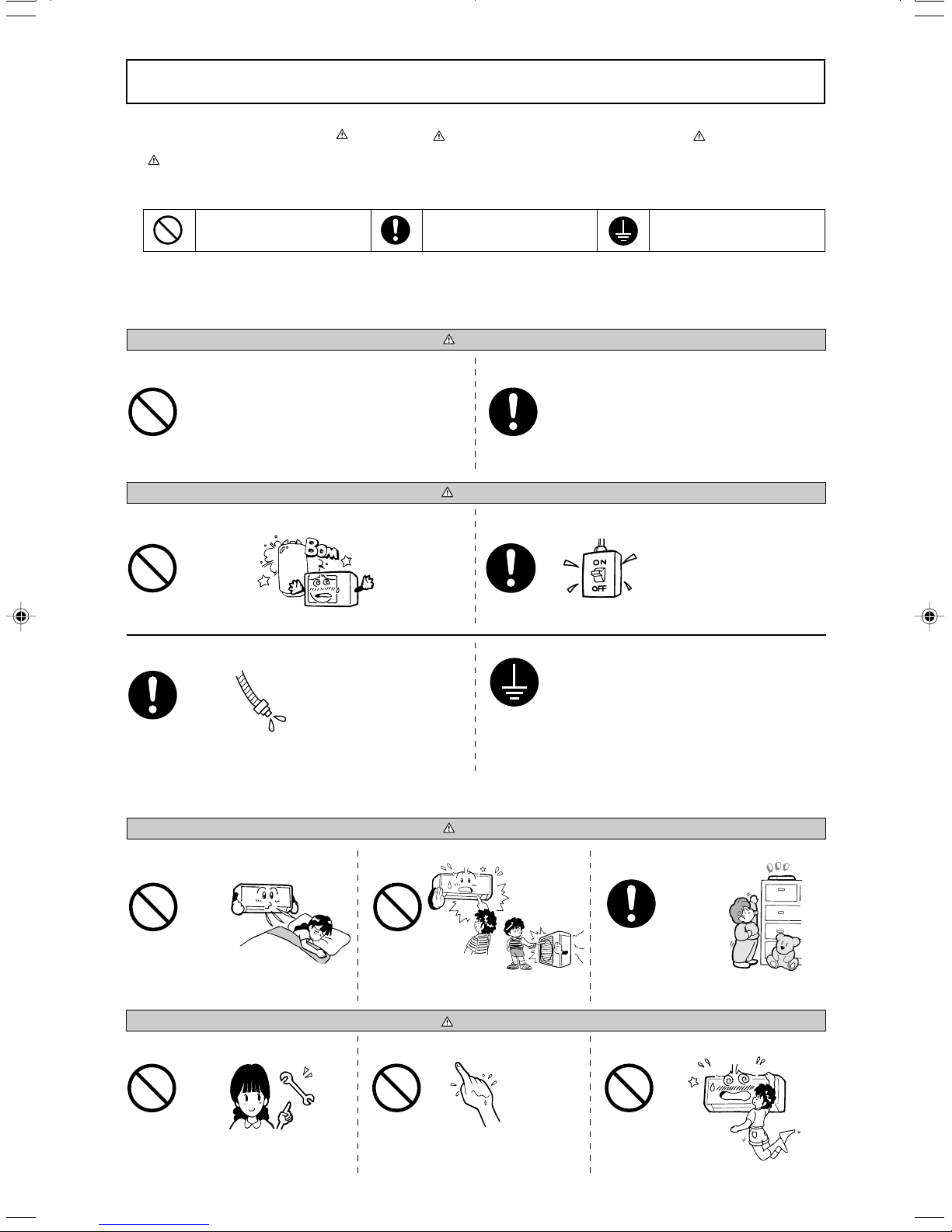
Safety precautions
• Before starting to use the system, please read these “Safety precautions” carefully to ensure proper operation of the system.
• The safety precautions are classified as “
improper handling could have dramatic consequences like death, serious injury, etc. Nevertheless, even precautions as shown in the column
CAUTION” might pose a serious problem, depending on the circumstances. Please observe these precautions with great care, since they are
“
essential to your safety.
• Symbols which appear frequently in the text have the following meaning:
DANGER” and “ CAUTION”. Precautions as shown in the column “ DANGER” indicate that
Strictly prohibited Provide positive earthing
• When you have read the instruction manual, please keep it near at hand for consultation. If someone else takes over as operator, make certain that the
manual is also passed on to the new operator.
Observe instructions with
great care
❚ INSTALLATION PRECAUTIONS
DANGER
The system is meant for domestic, residential etc. use.
If used in inferior environments, such as an engineering workplace, the equipment
may function poorly.
Do not install near places where inflammable gas may leak.
LPG
Gas leaks may cause fire.
Make sure that you drain the hose properly, so that all the
water has dripped out.
The system must be installed by your dealer or a qualified professional.
It is not advisable to install the system yourself, as faulty handling may cause leakage of water, electric shock or fire.
CAUTION
Depending on the place of installation, a circuit breaker may
be necessary.
If you don’t fit a circuit breaker, you may cause an electric shock.
Make sure that the system has been properly earthed.
Negligence may cause flooding in the room resulting in wet furniture.
❚ OPERATION PRECAUTIONS
Do not expose yourself to the cooling
air for prolonged periods.
This could affect your physical condition and cause
health problems.
Only use approved fuses.
Use of steel or copper wire instead of an approved
fuse is strictly forbidden, as it may cause a breakdown
or fire.
Do not insert anything into the air inlet.
This may cause injury, as the internal fan rotates at
high speed.
Do not handle the switches with wet
hands.
This may cause an electric shock.
Earth cables should never be connected to a gas pipe, municipal water pipe, lightning conductor or telephone earth cable. Incorrect installation of the earth cable
may produce an electric shock.
DANGER
Store the remote control out of reach
of infants.
Failure to observe this may result in the batteries
being swallowed or other accidents.
CAUTION
Don’t swing from the system.
If the system falls down,
you may get injured.
– 2 –
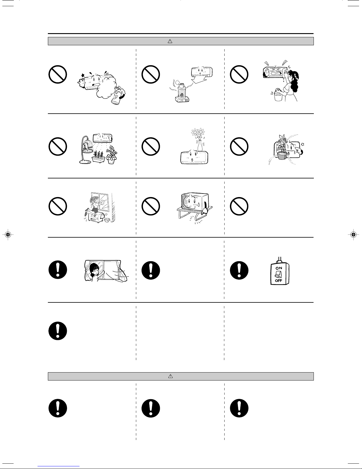
Safety precautions
CAUTION
Do not place a combustible insecticide
or paint spray near the blower, nor aim it
directly at the system.
This may result in a fire.
The system should only be used for its original purpose
and not for anything else like, for instance, preservation of
You should not expose any combustion appliance directly to the air
stream of the air-conditioner.
The appliance may then work inadequately.
Do not place anything containing water, like vases, on top of the unit.
food, plants or animals, precision devices or works of art.
The system is only intended for use in ordinary domestic rooms.
Any other use of the system may damage the quality of food, etc.
Do not sit on the outdoor unit nor put
anything on it.
Water entering the unit could damage the insulation and therefore cause an electric shock.
After a long period of use, check the unit's
support structure from time to time.
Do not wash the air-conditioner with water.
This could cause an electric shock.
Do not install the system at a place
where the air stream of the blower is
aimed directly at plants or animals.
This will damage their health.
Do not touch the aluminum fins on the
air heat exchanger.
If the unit falls down or things drop off it, people
could get hurt.
If you operate the system together with
a combustion appliance, you must regularly ventilate the indoor air.
Insufficient ventilation may cause accidents due to
oxygen deficiency.
If you don't repair any damage straightaway, the
unit may fall down and cause personal injury.
Stand firmly on a stepladder or other
stable object when removing the inlet
panel and filters.
Failure to observe this may result in injury through
insecure objects toppling over.
Do not place objects near the outdoor
unit or allow leaves to gather around the
unit.
If there are objects or leaves around the outdoor unit,
small animals may enter unit and contact electrical
parts resulting in break down, emission of smoke or
flame.
❚ PRECAUTIONS FOR TRANSFER OR REPAIRS
DANGER
Consult your dealer for repairs to the
system.
If the air-conditioner is moved elsewhere, contact your dealer or a professional fitter.
Failure to observe this may result in injury.
When you clean the system, stop the
unit and turn off the power switch.
Never clean the unit while the internal fan is rotating.
If you notice anything abnormal (smell of
burning, etc.), stop the system, turn off the
power switch and consult your dealer.
Wrong repairs could cause an electric shock, fire, etc.
Faulty installation may cause water leakage, electric shock, fire, etc.
– 3 –
Continued use of the system in abnormal circumstances may result in malfunctioning, electric shock,
fire, etc.
Choice of operations and features
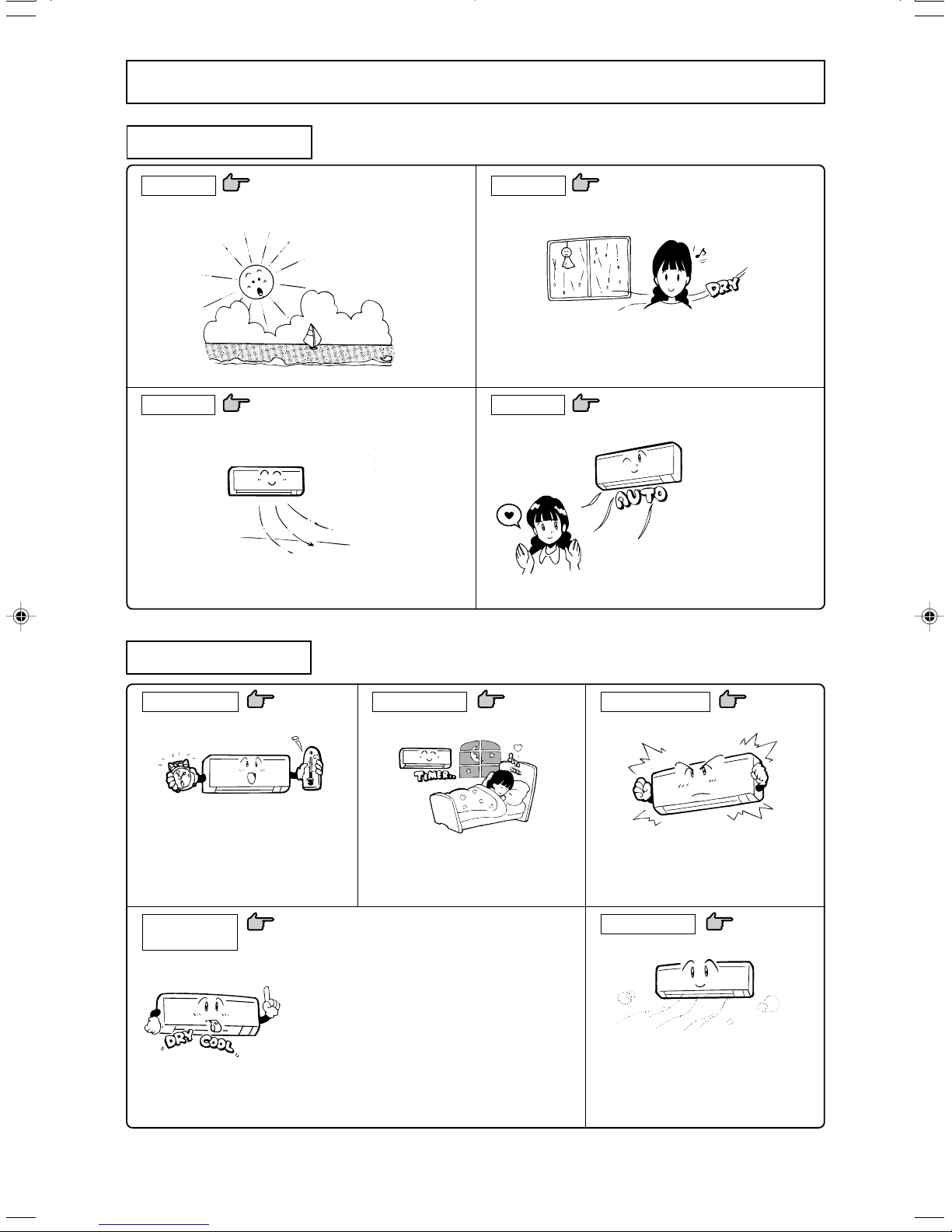
Choice of operations
COOL
Cooling by extracting heat from the room.
Fanning by circulating room air.
Page 9
Page 9
DRY
Drying by extracting damp from the room.
Functioning of microcomputer depends on setting and room temperatures. It dehumidifies while keeping room temperature almost
constant.
AUTOFAN
Automatic selection of operating mode.
Page 9
Page 8
The Auto mode automatically selects the operation
mode (COOL or DRY), depending on the room temperature when switched on.
Features
Amenity facility
When using the timer to switch on, the system should become operational shortly before the set time, depending on the room
temperature so that the desired temperature
should be reached at the set time.
Adjustment of
airflow
Page 13
Page 10
• MULTI-DIRECTIONAL AIR FLOW
This function sets the unit at the most suitable angle
for blowing, imitating a natural breeze.
• SWING FLAP
Flap moves up and down continuously.
• SWING LOUVER
Louver moves left and right continuously.
• MEMORY FLAP (FLAP OR LOUVER STOPPED)
Once the flap or louver position has been set, the unit
will memorise it and continue in the same position
the next time.
TIMER procedure
There are three timers, for SLEEP, ON and
OFF. They can be set as desired.
Page 11, 12
HIGH POWER mode
Turning up the power operates the air conditioner in the power cooling mode.
ECONOMY mode
This is an economic level of operation.
Page 14
Page 14
– 4 –
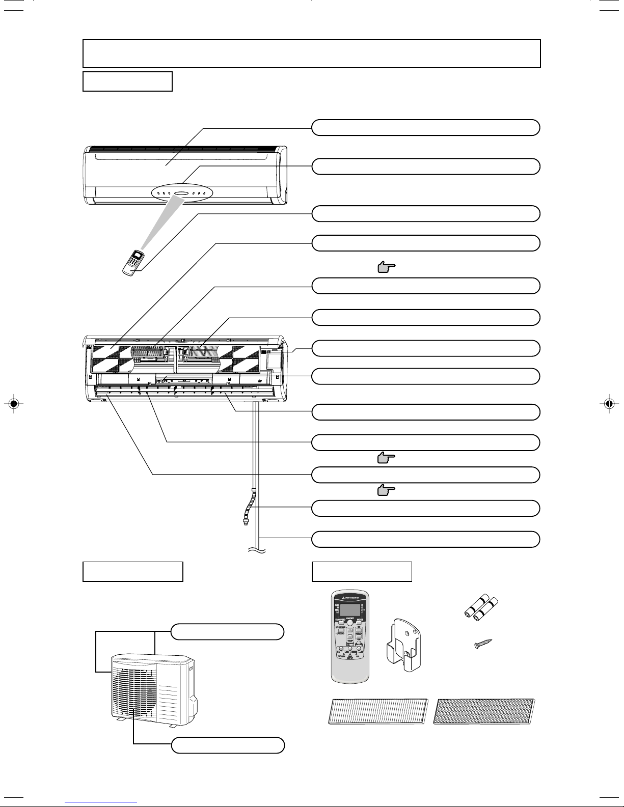
Name of each part and its function
INDOOR UNIT
SRK52CF-BN
SRK71CF-BN
SRK52CF-BP
SRK71CF-BP
Air inlet panel
Draws in the indoor air.
Unit indication section and remote control signal receiver
Wireless remote control
Air filter
Removes dust or dirt from the inlet air.
Page 17
Photocatalytic washable deodorizing filter
Natural enzyme filter
Room temperature detector
Unit operation switch
OUTDOOR UNIT
SRC52CF-BN
SRC71CF-BN
SRC52CF-BP
SRC71CF-BP
Air inlet
(on side & rear surface)
Air outlet
Air blows out of here.
Left/right air flow adjustment louver
Page 10
Up/down air flow direction adjustment flap
Page 10
Drain hose
Drains water from the dehumidified air.
Refrigerant piping connection electric flex
Accessories
Wireless remote control
Wireless remote
control holder
Battery (R03(AAA,Micro)×2)
Wood screw (Quantity:2)
(for remote control holder mounting)
* The appearance varies for Models 52 and 71.
Air outlet
– 5 –
Natural enzyme filter
(green)
Photocatalytic washable deodoriz-
ing filter (orange)
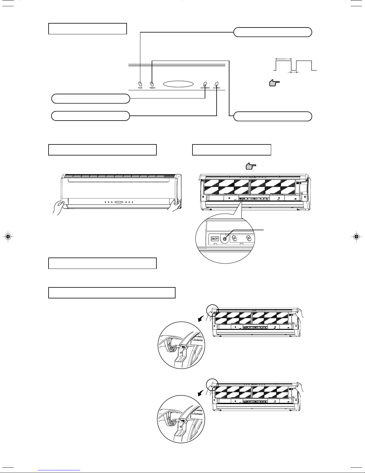
Unit indication section
HI POWER light (green)
Illuminates during HIGH POWER operation.
RUN light (green)
• Illuminates during operation.
• Blinks at the ‘CLEAN operation’.
3 sec.
CLEAN operation
ON
OFF
1 sec.
Page 15
ECONO light (orange)
Illuminates during ECONOMY operation.
How to open the air inlet panel
Place fingers at the recesses on both sides of the panel and pull up the panel
to this side so that it will be opened by about 60 degrees.
How to close the air inlet panel
Push both sides evenly and press further lightly at the center.
TIMER light (yellow)
Illuminates during TIMER operation.
Unit ON/OFF button
In emergencies, this button can be used for turning on/off the unit when re-
mote control is not available.
Page 15
Unit ON/OFF button
Removal, installation of air inlet panel
When removing the air inlet panel for internal cleaning or others, open the
panel by 80 degrees and then pull it to this side.
Secure either the upper or lower edge of the air inlet panel by lightly pushing it
in, and then close the panel.
– 6 –
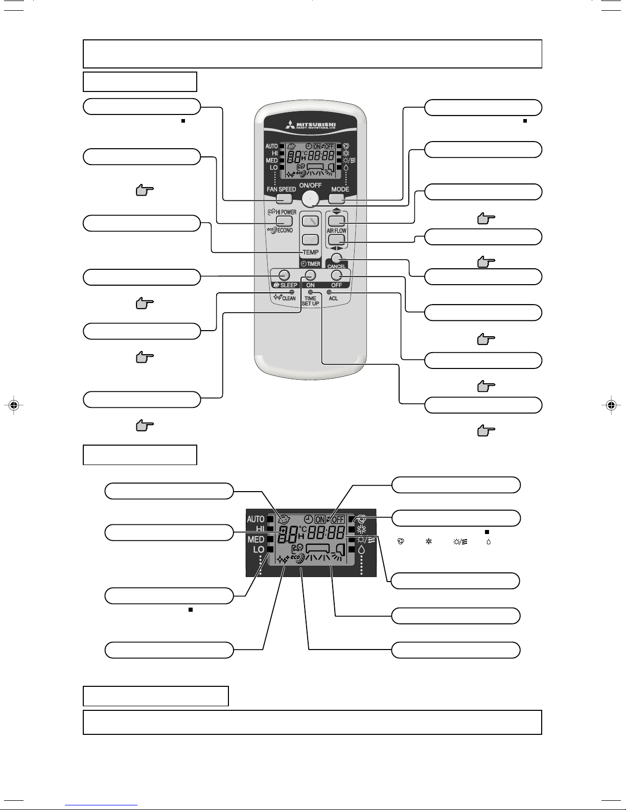
Operation and indication section for remote control
Operation section
FAN SPEED button
Each time the button is pushed, the indicator is switched over in turn.
HI POWER/ECONO button
This button changes the HIGH POWER/
ECONOMY mode.
Page 14
TEMPERATURE button
This button sets the room temperature.
(This button changes the present time and
TIMER time.)
SLEEP button
This button changes to SLEEP operation.
Page 11
CLEAN switch
This switch changes the CLEAN mode.
Page 15
ON TIMER button
This button selects ON TIMER operation.
Page 12
• The above illustration shows all controls, but in practice
only the relevant parts are shown.
OPERATION MODE select button
Each time the button is pushed, the indicator is switched over in turn.
ON/OFF (luminous) button
Press for starting operation, press again for
stopping.
AIR FLOW (UP/DOWN) button
This button changes the air flow (up/down) mode.
Page 10
AIR FLOW (LEFT/RIGHT) button
This button changes the air flow (left/right) mode.
Page 10
CANCEL button
This button cancels the ON timer, OFF
timer, and SLEEP operation.
OFF TIMER button
This button selects OFF TIMER operation.
Page 11
RESET switch
Switch for resetting microcomputer.
Page 16
TIME SET UP switch
This switch for setting the time.
Page 13
Indication section
SLEEP indicator
Indicates during SLEEP operation.
TEMPERATURE indicator
Indicates set temperature.
(Does not indicate temperature when operation
mode is on AUTO)
FAN SPEED indicator
Indicates set air flow rate with lamp.
CLEAN indicator
Indicates during CLEAN operation.
ON/OFF TIMER indicator
Indicates during ON/OFF TIMER operation.
OPERATION MODE indicator
Indicates selected operation with lamp.
[ (Auto) • (Cool) • (Fan) • (Dry)]
TIME indicator
Indicates present time or timer setting time.
AIR FLOW indicator
Shows selected flap and louver mode.
HI POWER/ECONO MODE indicator
Indicates during HIGH
mode operation.
POWER/ECONOMY
Transmission procedure
When each button on the remote control is pressed – with the remote control pointing towards the air-conditioner unit – a signal is transmitted.
When the air-conditioner receives the signal correctly, it will beep.
– 7 –
 Loading...