

Page 1

TECHNICAL MANUAL
Manual No.'10•SR-T-091D
INVERTER RESIDENTIAL AIR CONDITIONERS
(Split system, air to air heat pump type)
DRAFT
Wall mounted type
SRK50ZJ-S
SRK20ZJX-S
SRK25ZJX-S
SRK35ZJX-S
SRK50ZJX-S
SRK60ZJX-S
Floor standing type
SRF25ZJX-S
SRF35ZJX-S
SRF50ZJX-S
Ceiling concealed type
SRR25ZJ-S
SRR35ZJ-S
Ceiling cassette-4way compact type
FDTC25VD
FDTC35VD
Page 2
CONTENTS
1. SPECIFICATIONS ......................................................................................... 2
(1) Wall mounted type (SRK)
.........................................................................
2
(1) Indoor units
(1) Indoor units
............................................................................................. 15
(2) Floor standing type (SRF) ........................................................................ 8
(2) Outdoor units ............................................................................................20
(3) Remote controller .....................................................................................23
3. ELECTRICAL WIRING .................................................................................. 25
............................................................................................. 25
(2) Outdoor units ...........................................................................................30
(3) Ceiling concealed type (SRR) .................................................................. 11
(4) Ceiling cassette-4way compact type (FDTC) ...........................................13
2. EXTERIOR DIMENSIONS ............................................................................. 15
■How to read the model name
Example: SRK 20 Z
Series code
Inveter type
Product capacity
Model name SRK : Wall mounted type
SRC : Outdoor unit
SRF : Floor standing type
SRR : Ceiling concealed type
FDTC : Ceiling cassette-4way
compact type
JX-S
'10 • SR-T-091D
-
-
1
Page 3
-
2
-
'10 • SR-T-091D
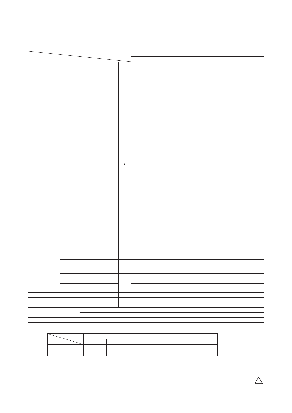
1. SPECIFICATIONS
(1) Wall mounted type (SRK)
Item
Cooling capacity (1) W 5000 (1600 (Min.)~5500 (Max.))
Heating capacity (1) W 5800 (1600 (Min.)~6600 (Max.))
Power supply 1 Phase, 220~240 V, 50Hz
Power
consumption
Running
current
Operation
data (1)
Exterior dimensions (Height x Width x Depth) mm 294 x 798 x 229 640 x 800 (+71) x 290
Exterior appearance
(Munsell color)
Net weight kg 9.5 42
Refrigerant
equipment
Air handling
equipment
Shock & vibration absorber — Cushion rubber (for compressor)
Electric heater — —
Operation
control
Safety devices
Installation
data
Drain hose Connectable (VP16) —
Power cable —
Recommended breaker size A 16
Connection wiring
Accessories (included)
Optional parts Interface kit (SC-BIKN-E)
Note (1) The data are measured at the following conditions.
Inrush current 7.3 / 7.0 / 6.7 (220/ 230/ 240 V)
COP
Cooling
Noise
level
Heating
Compressor type & Q'ty — 5RS132XAB21 (Rotary type) x 1
Motor (Starting method) kW — 0.90 (Line starting)
Refrigerant oil 0.37 (FV50S)
Refrigerant (4) kg R410A 1.35 (Pre-Charged up to the piping length of 15m)
Heat exchanger Louver fins & inner grooved tubing M fins & inner grooved tubing
Refrigerant control Capillary tubes + Electronic expansion valve
Deice control Microcomputer control
Fan type & Q'ty Tangential fan x 1 Propeller fan x 1
Motor W 38 34
Air flow
Fresh air intake Not possible —
Air filter, Quality / Quantity Polypropylene net (washable) x 2 —
Operation switch Wireless-Remote control —
Room temperature control Microcomputer thermostat —
Operation Display RUN : Green, TIMER : Yellow, HI POWER : Green, 3D AUTO : Green
Refrigerant piping size (O.D) mm Liquid line :φ6.35 (1/4") Gas line :φ12.7 (1/2")
Connecting method Flare connecting
Attached length of piping m
Insulation for piping Necessary (Both sides), independent
Refrigerant line (one way) length
Vertical height difference between
outdoor unit and indoor unit
Item
Operation
Cooling 27˚C 19˚C 35˚C 24˚C
Heating 20˚C — 7˚C 6˚C
(2) This air-conditioner is manufactured and tested in conformity with the ISO.
(3) The operation data are applied to the 220/230/240V districts respectively.
(4) The refrigerant quantity to be charged includes the refrigerant in 15m connecting piping.
(Purging is not required even for the short piping.)
Cooling
Heating 1.59 (0.42~2.10)
Cooling
Heating 7.3 / 7.0 / 6.7 (220/ 230/ 240 V)
Cooling 3.23
Heating 3.65
Sound level dB(A) Hi : 46 Me : 37 Lo : 26 51
Power level dB 61 61
Sound level dB(A) Hi : 45 Me : 37 Lo : 31 53
Power level dB 61 63
Cooling
Heating Hi : 13.5 Me : 10.2 Lo : 7.5 36.0
Size x Core number 1.5mm2 x 4 cores (Including earth cable)
Connecting method Terminal block (Screw fixing type)
Indoor air temperature Outdoor air temperature
DB WB DB WB
Model
kW
A
CMM
m
Indoor unit SRK50ZJ-S Outdoor unit SRC50ZJ-S
7.1 / 6.8 / 6.5 (220/ 230/ 240 V)
Fine snow
( 8.0Y 9.3/0.1 ) near equivalent
Hi : 11.3 Me : 7.8 Lo : 5.3 36.0
Compressor overheat protection, Overcurrent protection,
Frost protection, Serial signal error protection, Indoor fan motor error protection,
Heating overload protection (High pressure control), Cooling overload protection
Liquid line : 0.53
Gas line : 0.40
Max. 15 (Outdoor unit is higher)
Mounting kit, Clean filter (Allergen clear filter x 1, Photocatalytic washable deodorizing filter x 1)
SRK50ZJ-S
1.55 (0.40~2.20)
Max. 25
Max. 15 (Outdoor unit is lower)
The pipe length is 7.5m.
Standards
ISO-T1, JIS C 9612
Adapted to RoHS directive
Stucco white
( 4.2Y 7.5/1.1 ) near equivalent
—
RWA0 0 0 Z225
B
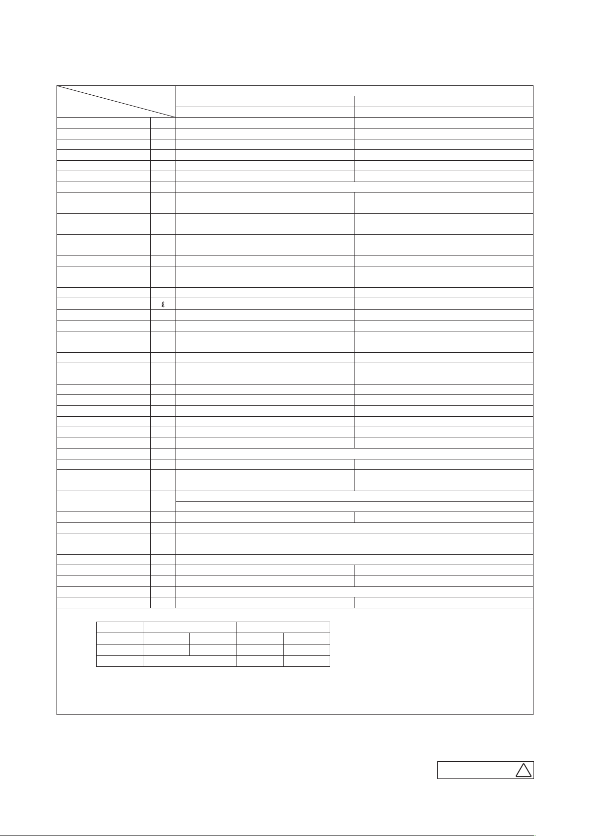
Page 4

'10 • SR-T-091D
Adapted to RoHS directive
Item
Cooling capacity (1) W 2000 (900 (Min.)~3100 (Max.))
Heating capacity (1) W 2500 (900 (Min.)~4300 (Max.))
Power supply 1 Phase, 220~240 V, 50Hz
Power
consumption
Running
current
Operation
data (1)
Exterior dimensions (Height x Width x Depth) mm 309 x 890 x 220 595 x 780 (+62) x 290
Exterior appearance
(Munsell color)
Net weight kg 15 38
Refrigerant
equipment
Air handling
equipment
Shock & vibration absorber — Cushion rubber (for compressor)
Electric heater — —
Operation
control
Safety devices
Installation
data
Drain hose Connectable (VP16) —
Power cable —
Recommended breaker size A 16
Connection wiring
Accessories (included)
Optional parts Interface kit (SC-BIKN-E)
Note (1) The data are measured at the following conditions.
Inrush current 2.4 / 2.3 / 2.2 (220/ 230/ 240 V)
COP
Cooling
Noise
level
Heating
Compressor type & Q'ty — RM-B5077MDE1 (Rotary type) x 1
Motor (Starting method) kW — 0.75 (Line starting)
Refrigerant oil 0.35 (DIAMOND FREEZE MA68)
Refrigerant (4) kg R410A 1.2 (Pre-Charged up to the piping length of 15m)
Heat exchanger Louver fins & inner grooved tubing M fins & inner grooved tubing
Refrigerant control Capillary tubes + Electronic expansion valve
Deice control Microcomputer control
Fan type & Q'ty Tangential fan x 1 Propeller fan x 1
Motor 27 24
Air flow
Fresh air intake Not possible —
Air filter, Quality / Quantity Polypropylene net (washable) x 2 —
Operation switch Wireless-Remote control —
Room temperature control Microcomputer thermostat —
Operation Display
Refrigerant piping size (O.D) mm Liquid line :φ6.35 (1/4") Gas line :φ9.52 (3/8")
Connecting method Flare connecting
Attached length of piping m
Insulation for piping Necessary (Both sides), independent
Refrigerant line (one way) length
Vertical height difference between
outdoor unit and indoor unit
Item
Operation
Cooling 27˚C 19˚C 35˚C 24˚C
Heating 20˚C — 7˚C 6˚C
(2) This air-conditioner is manufactured and tested in conformity with the ISO.
(3) The operation data are applied to the 220/230/240V districts respectively.
(4) The refrigerant quantity to be charged includes the refrigerant in 15m connecting piping.
(Purging is not required even for the short piping.)
Cooling
Heating 0.45 (0.23~1.00)
Cooling
Heating 2.4 / 2.3 / 2.2 (220/ 230/ 240 V)
Cooling 5.71
Heating 5.56
Sound level dB(A) Hi : 39 Me : 30 Lo : 21 47
Power level dB 53 60
Sound level dB(A) Hi : 38 Me : 33 Lo : 25 47
Power level dB 54 59
Cooling
Heating Hi : 12.0 Me : 9.5 Lo : 7.0 27.0
Size x Core number 1.5mm2 x 4 cores (Including earth cable)
Connecting method Terminal block (Screw fixing type)
Indoor air temperature Outdoor air temperature
DB WB DB WB
Model
kW
A
CMM
m
Indoor unit SRK20ZJX-S Outdoor unit SRC20ZJX-S
Fine snow
( 8.0Y 9.3/0.1 ) near equivalent
Hi : 11.5 Me : 8.0 Lo : 5.0 29.5
RUN : Green, TIMER : Yellow, HI POWER : Green,
3D AUTO : Green, ECONO : Blue
Compressor overheat protection, Overcurrent protection,
Frost protection, Serial signal error protection, Indoor fan motor error protection,
Heating overload protection (High pressure control), Cooling overload protection
Liquid line : 0.55
Gas line : 0.49
Mounting kit, Clean filter (Allergen clear filter x 1, Photocatalytic washable deodorizing filter x 1)
SRK20ZJX-S
0.35 (0.19~0.70)
1.9 / 1.8 / 1.7 (220/ 230/ 240 V)
Stucco white
( 4.2Y 7.5/1.1 ) near equivalent
—
Max. 15
Max. 10 (Outdoor unit is higher)
Max. 10 (Outdoor unit is lower)
The pipe length is 7.5m.
Standards
ISO-T1, JIS C 9612
RWA0 0 0 Z229
-
-
3
B
Page 5

-
4
-
'10 • SR-T-091D
Adapted to RoHS directive
Item
Cooling capacity (1) W 2550 (900 (Min.)~3200 (Max.))
Heating capacity (1) W 3130 (900 (Min.)~4700 (Max.))
Power supply 1 Phase, 220~240 V, 50Hz
Power
consumption
Running
current
Operation
data (1)
Exterior dimensions (Height x Width x Depth) mm 309 x 890 x 220 595 x 780 (+62) x 290
Exterior appearance
(Munsell color)
Net weight kg 15 38
Refrigerant
equipment
Air handling
equipment
Shock & vibration absorber — Cushion rubber (for compressor)
Electric heater — —
Operation
control
Safety devices
Installation
data
Drain hose Connectable (VP16) —
Power cable —
Recommended breaker size A 16
Connection wiring
Accessories (included)
Optional parts Interface kit (SC-BIKN-E)
Note (1) The data are measured at the following conditions.
Inrush current 3.1 / 2.9 / 2.8 (220/ 230/ 240 V)
COP
Cooling
Noise
level
Heating
Compressor type & Q'ty — RM-B5077MDE1 (Rotary type) x 1
Motor (Starting method) kW — 0.75 (Line starting)
Refrigerant oil 0.35 (DIAMOND FREEZE MA68)
Refrigerant (4) kg R410A 1.2 (Pre-Charged up to the piping length of 15m)
Heat exchanger Louver fins & inner grooved tubing M fins & inner grooved tubing
Refrigerant control Capillary tubes + Electronic expansion valve
Deice control Microcomputer control
Fan type & Q'ty Tangential fan x 1 Propeller fan x 1
Motor W 27 24
Air flow
Fresh air intake Not possible —
Air filter, Quality / Quantity Polypropylene net (washable) x 2 —
Operation switch Wireless-Remote control —
Room temperature control Microcomputer thermostat —
Operation Display
Refrigerant piping size (O.D) mm Liquid line :φ6.35 (1/4") Gas line :φ9.52 (3/8")
Connecting method Flare connecting
Attached length of piping m
Insulation for piping Necessary (Both sides), independent
Refrigerant line (one way) length
Vertical height difference between
outdoor unit and indoor unit
Item
Operation
Cooling 27˚C 19˚C 35˚C 24˚C
Heating 20˚C — 7˚C 6˚C
(2) This air-conditioner is manufactured and tested in conformity with the ISO.
(3) The operation data are applied to the 220/230/240V districts respectively.
(4) The refrigerant quantity to be charged includes the refrigerant in 15m connecting piping.
(Purging is not required even for the short piping.)
Cooling
Heating 0.595 (0.23~1.12)
Cooling
Heating 3.1 / 2.9 / 2.8 (220/ 230/ 240 V)
Cooling 5.20
Heating 5.26
Sound level dB(A) Hi : 41 Me : 31 Lo : 22 47
Power level dB 55 60
Sound level dB(A) Hi : 41 Me : 34 Lo : 27 47
Power level dB 58 60
Cooling
Heating Hi : 13.0 Me : 10.0 Lo : 7.5 27.0
Size x Core number 1.5mm2 x 4 cores (Including earth cable)
Connecting method Terminal block (Screw fixing type)
Indoor air temperature Outdoor air temperature
DB WB DB WB
Model
kW
A
CMM
m
Indoor unit SRK25ZJX-S Outdoor unit SRC25ZJX-S
Fine snow
( 8.0Y 9.3/0.1 ) near equivalent
Hi : 12.5 Me : 9.0 Lo : 5.0 29.5
RUN : Green, TIMER : Yellow, HI POWER : Green,
3D AUTO : Green, ECONO : Blue
Compressor overheat protection, Overcurrent protection,
Frost protection, Serial signal error protection, Indoor fan motor error protection,
Heating overload protection (High pressure control), Cooling overload protection
Liquid line : 0.55
Gas line : 0.49
Mounting kit, Clean filter (Allergen clear filter x 1, Photocatalytic washable deodorizing filter x 1)
SRK25ZJX-S
0.49 (0.19~0.82)
2.5 / 2.4 / 2.3 (220/ 230/ 240 V)
Stucco white
( 4.2Y 7.5/1.1 ) near equivalent
—
Max. 15
Max. 10 (Outdoor unit is higher)
Max. 10 (Outdoor unit is lower)
The pipe length is 7.5m.
Standards
ISO-T1, JIS C 9612
RWA0 0 0 Z229
B
Page 6

'10 • SR-T-091D
Adapted to RoHS directive
Item
Cooling capacity (1) W 3500 (900 (Min.)~4100 (Max.))
Heating capacity (1) W 4300 (900 (Min.)~5100 (Max.))
Power supply 1 Phase, 220~240 V, 50Hz
Power
consumption
Running
current
Operation
data (1)
Exterior dimensions (Height x Width x Depth) mm 309 x 890 x 220 595 x 780 (+62) x 290
Exterior appearance
(Munsell color)
Net weight kg 15 38
Refrigerant
equipment
Air handling
equipment
Shock & vibration absorber — Cushion rubber (for compressor)
Electric heater — —
Operation
control
Safety devices
Installation
data
Drain hose Connectable (VP16) —
Power cable —
Recommended breaker size A 16
Connection wiring
Accessories (included)
Optional parts Interface kit (SC-BIKN-E)
Note (1) The data are measured at the following conditions.
Inrush current 4.6 / 4.4 / 4.2 (220/ 230/ 240 V)
COP
Cooling
Noise
level
Heating
Compressor type & Q'ty — RM-B5077MDE1 (Rotary type) x 1
Motor (Starting method) kW — 0.90 (Line starting)
Refrigerant oil 0.35 (DIAMOND FREEZE MA68)
Refrigerant (4) kg R410A 1.2 (Pre-Charged up to the piping length of 15m)
Heat exchanger Louver fins & inner grooved tubing M fins & inner grooved tubing
Refrigerant control Capillary tubes + Electronic expansion valve
Deice control Microcomputer control
Fan type & Q'ty Tangential fan x 1 Propeller fan x 1
Motor W 27 24
Air flow
Fresh air intake Not possible —
Air filter, Quality / Quantity Polypropylene net (washable) x 2 —
Operation switch Wireless-Remote control —
Room temperature control Microcomputer thermostat —
Operation Display
Refrigerant piping size (O.D) mm Liquid line :φ6.35 (1/4") Gas line :φ9.52 (3/8")
Connecting method Flare connecting
Attached length of piping m
Insulation for piping Necessary (Both sides), independent
Refrigerant line (one way) length
Vertical height difference between
outdoor unit and indoor unit
Item
Operation
Cooling 27˚C 19˚C 35˚C 24˚C
Heating 20˚C — 7˚C 6˚C
(2) This air-conditioner is manufactured and tested in conformity with the ISO.
(3) The operation data are applied to the 220/230/240V districts respectively.
(4) The refrigerant quantity to be charged includes the refrigerant in 15m connecting piping.
(Purging is not required even for the short piping.)
Cooling
Heating 0.960 (0.23~1.35)
Cooling
Heating 4.6 / 4.4 / 4.2 (220/ 230/ 240 V)
Cooling 4.14
Heating 4.48
Sound level dB(A) Hi : 43 Me : 33 Lo : 22 50
Power level dB 58 63
Sound level dB(A) Hi : 42 Me : 35 Lo : 27 50
Power level dB 59 62
Cooling
Heating Hi : 14.0 Me : 11.0 Lo : 8.0 29.5
Size x Core number 1.5mm2 x 4 cores (Including earth cable)
Connecting method Terminal block (Screw fixing type)
Indoor air temperature Outdoor air temperature
DB WB DB WB
Model
kW
A
CMM
m
Indoor unit SRK35ZJX-S Outdoor unit SRC35ZJX-S
Fine snow
( 8.0Y 9.3/0.1 ) near equivalent
Hi : 13.5 Me : 9.5 Lo : 5.0 32.5
RUN : Green, TIMER : Yellow, HI POWER : Green,
3D AUTO : Green, ECONO : Blue
Compressor overheat protection, Overcurrent protection,
Frost protection, Serial signal error protection, Indoor fan motor error protection,
Heating overload protection (High pressure control), Cooling overload protection
Liquid line : 0.55
Gas line : 0.49
Mounting kit, Clean filter (Allergen clear filter x 1, Photocatalytic washable deodorizing filter x 1)
SRK35ZJX-S
0.845 (0.19~1.01)
4.0 / 3.8 / 3.6 (220/ 230/ 240 V)
Stucco white
( 4.2Y 7.5/1.1 ) near equivalent
—
Max. 15
Max. 10 (Outdoor unit is higher)
Max. 10 (Outdoor unit is lower)
The pipe length is 7.5m.
Standards
ISO-T1, JIS C 9612
RWA0 0 0 Z229
-
-
5
B
Page 7

-
6
-
'10 • SR-T-091D
Adapted to RoHS directive
Item
Cooling capacity (1) W 5000 (700 (Min.)~6200 (Max.))
Heating capacity (1) W 6000 (700 (Min.)~8800 (Max.))
Power supply 1 Phase, 220~240 V, 50Hz
Power
consumption
Running
current
Operation
data (1)
Exterior dimensions (Height x Width x Depth) mm 309 x 890 x 220 640 x 800 (+71) x 290
Exterior appearance
(Munsell color)
Net weight kg 15 43
Refrigerant
equipment
Air handling
equipment
Shock & vibration absorber — Cushion rubber (for compressor)
Electric heater — —
Operation
control
Safety devices
Installation
data
Drain hose Connectable (VP16) —
Power cable —
Recommended breaker size A 16
Connection wiring
Accessories (included)
Optional parts Interface kit (SC-BIKN-E)
Note (1) The data are measured at the following conditions.
Inrush current 6.2 / 5.9 / 5.7 (220/ 230/ 240 V)
COP
Cooling
Noise
level
Heating
Compressor type & Q'ty — 5CS130XGB04 (Scroll type) x 1
Motor (Starting method) kW — 0.9 (Line starting)
Refrigerant oil 0.48 (RB68A or Freol Alpha 68M)
Refrigerant (3) kg R410A 1.4 (Pre-Charged up to the piping length of 15m)
Heat exchanger Louver fins & inner grooved tubing M fins & inner grooved tubing
Refrigerant control Capillary tubes + Electronic expansion valve
Deice control Microcomputer control
Fan type & Q'ty Tangential fan x 1 Propeller fan x 1
Motor W 27 34
Air flow
Fresh air intake Not possible —
Air filter, Quality / Quantity Polypropylene net (washable) x 2 —
Operation switch Wireless-Remote control —
Room temperature control Microcomputer thermostat —
Operation Display
Refrigerant piping size (O.D) mm Liquid line :φ6.35 (1/4") Gas line :φ12.7 (1/2")
Connecting method Flare connecting
Attached length of piping m
Insulation for piping Necessary (Both sides), independent
Refrigerant line (one way) length
Vertical height difference between
outdoor unit and indoor unit
Item
Operation
Cooling 27˚C 19˚C 35˚C 24˚C
Heating 20˚C — 7˚C 6˚C
(2) This air-conditioner is manufactured and tested in conformity with the ISO.
(3) The operation data are applied to the 220/230/240V districts respectively.
(4) The refrigerant quantity to be charged includes the refrigerant in 15m connecting piping.
(Purging is not required even for the short piping.)
Cooling
Heating 1.35 (0.2~2.26)
Cooling
Heating 6.2 / 5.9 / 5.7 (220/ 230/ 240 V)
Cooling 3.85
Heating 4.44
Sound level dB(A) Hi : 45 Me : 38 Lo : 26 48
Power level dB 60 62
Sound level dB(A) Hi : 45 Me : 38 Lo : 32 48
Power level dB 62 62
Cooling
Heating Hi : 16.5 Me : 14.5 Lo : 10.5 33.0
Size x Core number 1.5mm2 x 4 cores (Including earth cable)
Connecting method Terminal block (Screw fixing type)
Indoor air temperature Outdoor air temperature
DB WB DB WB
Model
kW
A
CMM
m
Indoor unit SRK50ZJX-S Outdoor unit SRC50ZIX-S
Fine snow
( 8.0Y 9.3/0.1 ) near equivalent
Hi : 13.5 Me : 11 Lo: 8 36.0
RUN : Green, TIMER : Yellow, HI POWER : Green,
3D AUTO : Green, ECONO : Blue
Compressor overheat protection, Overcurrent protection,
Frost protection, Serial signal error protection, Indoor fan motor error protection,
Heating overload protection (High pressure control), Cooling overload protection
Liquid line : 0.55
Gas line : 0.49
Mounting kit, Clean filter (Allergen clear filter x 1, Photocatalytic washable deodorizing filter x 1)
SRK50ZJX-S
1.30 (0.2~2.20)
6.0 / 5.7 / 5.5 (220/ 230/ 240 V)
Stucco white
( 4.2Y 7.5/1.1 ) near equivalent
—
Max. 30
Max. 20 (Outdoor unit is higher)
Max. 20 (Outdoor unit is lower)
The pipe length is 7.5m.
Standards
ISO-T1, JIS C 9612
RWA0 0 0 Z229
B
Page 8

'10 • SR-T-091D
Adapted to RoHS directive
Item
Cooling capacity (1) W 6000 (800 (Min.)~6800 (Max.))
Heating capacity (1) W 6800 (800 (Min.)~9700 (Max.))
Power supply 1 Phase, 220~240 V, 50Hz
Power
consumption
Running
current
Operation
data (1)
Exterior dimensions (Height x Width x Depth) mm 309 x 890 x 220 640 x 800 (+71) x 290
Exterior appearance
(Munsell color)
Net weight kg 15 43
Refrigerant
equipment
Air handling
equipment
Shock & vibration absorber — Cushion rubber (for compressor)
Electric heater — —
Operation
control
Safety devices
Installation
data
Drain hose Connectable (VP 16) —
Power cable —
Recommended breaker size A 16
Connection wiring
Accessories (included)
Optional parts Interface kit (SC-BIKN-E)
Note (1) The data are measured at the following conditions.
Inrush current 8.5 / 8.2 / 7.8 (220/ 230/ 240 V)
COP
Cooling
Noise
level
Heating
Compressor type & Q'ty — 5CS130XGB04 (Scroll type) x 1
Motor (Starting method) kW — 0.9 (Line starting)
Refrigerant oil 0.48 (RB68A or Freol Alpha 68M)
Refrigerant (3) kg R410A 1.4 (Pre-Charged up to the piping length of 15m)
Heat exchanger Louver fins & inner grooved tubing M fins & inner grooved tubing
Refrigerant control Capillary tubes + Electronic expansion valve
Deice control Microcomputer control
Fan type & Q'ty Tangential fan x 1 Propeller fan x 1
Motor W 27 34
Air flow
Fresh air intake Not possible —
Air filter, Quality / Quantity Polypropylene net (washable) x 2 —
Operation switch Wireless-Remote control —
Room temperature control Microcomputer thermostat —
Operation Display
Refrigerant piping size (O.D) mm Liquid line :φ6.35 (1/4") Gas line :φ12.7 (1/2")
Connecting method Flare connecting
Attached length of piping m
Insulation for piping Necessary (Both sides), independent
Refrigerant line (one way) length
Vertical height difference between
outdoor unit and indoor unit
Item
Operation
Cooling 27˚C 19˚C 35˚C 24˚C
Heating 20˚C — 7˚C 6˚C
(2) This air-conditioner is manufactured and tested in conformity with the ISO.
(3) The operation data are applied to the 220/230/240V districts respectively.
(4) The refrigerant quantity to be charged includes the refrigerant in 15m connecting piping.
(Purging is not required even for the short piping.)
Cooling
Heating 1.67 (0.25~2.70)
Cooling
Heating 7.7 / 7.3 / 7.0 (220/ 230/ 240 V)
Cooling 3.23
Heating 4.07
Sound level dB(A) Hi : 47 Me : 38 Lo : 26 51
Power level dB 62 65
Sound level dB(A) Hi : 45 Me : 39 Lo : 33 51
Power level dB 62 65
Cooling
Heating Hi : 17.0 Me : 15.0 Lo : 11.0 36.0
Size x Core number 1.5mm2 x 4 cores (Including earth cable)
Connecting method Terminal block (Screw fixing type)
Indoor air temperature Outdoor air temperature
DB WB DB WB
Model
kW
A
CMM
m
Indoor unit SRK60ZJX-S Outdoor unit SRC60ZIX-S
Fine snow
( 8.0Y 9.3/0.1 ) near equivalent
Hi : 14.5 Me : 12.5 Lo : 8.5 41.5
RUN : Green, TIMER : Yellow, HI POWER : Green,
3D AUTO : Green, ECONO : Blue
Compressor overheat protection, Overcurrent protection,
Frost protection, Serial signal error protection, Indoor fan motor error protection,
Heating overload protection (High pressure control), Cooling overload protection
Liquid line : 0.55
Gas line : 0.49
Mounting kit, Clean filter (Allergen clear filter x 1, Photocatalytic washable deodorizing filter x 1)
SRK60ZJX-S
1.86 (0.25~2.30)
8.5 / 8.2 / 7.8 (220/ 230/ 240 V)
Stucco white
( 4.2Y 7.5/1.1 ) near equivalent
—
Max. 30
Max. 20 (Outdoor unit is higher)
Max.20 (Outdoor unit is lower)
The pipe length is 7.5m.
Standards
ISO-T1, JIS C 9612
RWA0 0 0 Z229
-
-
7
B
Page 9

-
8
-
'10 • SR-T-091D
(2) Floor standing type (SRF)
Item
Cooling capacity (1) W 2500 (900 (Min.)~3200 (Max.))
Heating capacity (1) W 3400 (900 (Min.)~4700 (Max.))
Power supply 1 Phase, 220~240 V, 50Hz
Power
consumption
Running
current
Operation
data (1)
Exterior dimensions (Height x Width x Depth) mm 600 x 860 x 238 595 x 780 x 290
Exterior appearance
( Munsell color )
Net weight kg 18 38
Refrigerant
equipment
Air handling
equipment
Shock & vibration absorber — Cushion rubber (for compressor)
Electric heater — —
Operation
control
Safety devices
Installation
data
Drain hose Connectable (VP16) —
Power cable —
Recommended breaker size A 16
Connection wiring
Accessories (included)
Optional parts Interface kit (SC-BIKN-E)
Note (1) The data are measured at the following conditions.
Inrush current 3.6 / 3.4 / 3.3 (220/ 230/ 240 V)
COP
Cooling
Noise
level
Heating
Compressor type & Q'ty — RM-B5077MDE1 (Rotary type) x 1
Motor (Starting method) kW — 0.75 (Line starting)
Refrigerant oil 0.35 (DIAMOND FREEZE MA68)
Refrigerant (3) kg R410A 1.2 (Pre-Charged up to the piping length of 15m)
Heat exchanger Louver fins & inner grooved tubing M fins & inner grooved tubing
Refrigerant control Capillary tubes + Electronic expansion valve
Deice control Microcomputer control
Fan type & Q'ty Turbo fan x 1 Propeller fan x 1
Motor W 40 24
Air flow
Fresh air intake Impossible —
Air filter, Quality / Quantity Polypropylene net (washable) x 1 —
Operation switch Wireless-Remote control —
Room temperature control Microcomputer thermostat —
Operation Display
Refrigerant piping size (O.D) mm Liquid line :φ6.35 (1/4") Gas line :φ9.52 (3/8")
Connecting method Flare connecting
Attached length of piping m — —
Insulation for piping Necessary (Both sides), independent
Refrigerant line (one way) length
Vertical height difference between
outdoor unit and indoor unit
Item
Operation
Cooling 27˚C 19˚C 35˚C 24˚C
Heating 20˚C — 7˚C 6˚C
(2) This air-conditioner is manufactured and tested in conformity with the ISO.
(3) The operation data are applied to the 220/230/240V districts respectively.
(4) The refrigerant quantity to be charged includes the refrigerant in 15m connecting piping.
(Purging is not required even for the short piping.)
Cooling
Heating 0.723 (0.23~1.20)
Cooling
Heating 3.6 / 3.4 / 3.3 (220/ 230/ 240 V)
Cooling 4.80
Heating 4.70
Sound level dB(A) Hi : 40 Me : 32 Lo : 26 47
Power level dB 51 60
Sound level dB(A) Hi : 40 Me : 35 Lo : 28 47
Power level dB 51 60
Cooling
Heating Hi : 10.5 Me : 8.2 Lo : 6.6 27.0
Size x Core number 1.5mm2 x 4 cores (Including earth cable)
Connecting method Terminal block (Screw fixing type)
Indoor air temperature Outdoor air temperature
DB WB DB WB
Model
kW
A
CMM
m
Indoor unit SRF25ZJX-S Outdoor unit SRC25ZJX-S
Fine snow
( 8.0Y 9.3/0.1 ) near equivalent
Hi : 9.0 Me : 7.6 Lo : 5.8 29.5
RUN : Green, TIMER : Yellow, HI POWER : Green,
AIR OUTLET SELECTION : Green, ECONO : Green
Compressor overheat protection, Overcurrent protection,
Frost protection, Serial signal error protection, Indoor fan motor error protection,
Heating overload protection (High pressure control), Cooling overload protection
Mounting kit, Clean filter (Natural enzyme filter x 1, Photocatalytic washable deodorizing filter x 1)
SRF25ZJX-S
0.521 (0.19~0.82)
2.6 / 2.5 / 2.4 (220/ 230/ 240 V)
Max. 15
Max. 10 (Outdoor unit is higher)
Max. 10 (Outdoor unit is lower)
The pipe length is 7.5m.
Standards
ISO-T1, JIS C 9612
Adapted to RoHS directive
Stucco white
( 4.2Y 7.5/1.1 ) near equivalent
RW B 000Z0 5 3
A
Page 10

'10 • SR-T-091D
Adapted to RoHS directive
Item
Cooling capacity (1) W 3500 (900 (Min.)~4100 (Max.))
Heating capacity (1) W 4500 (900 (Min.)~5100 (Max.))
Power supply 1 Phase, 220~240 V, 50Hz
Power
consumption
Running
current
Operation
data (1)
Exterior dimensions (Height x Width x Depth) mm 600 x 860 x 238 595 x 780 x 290
Exterior appearance
( Munsell color )
Net weight kg 19 38
Refrigerant
equipment
Air handling
equipment
Shock & vibration absorber — Cushion rubber (for compressor)
Electric heater — —
Operation
control
Safety devices
Installation
data
Drain hose Connectable (VP16) —
Power cable —
Recommended breaker size A 16
Connection wiring
Accessories (included)
Optional parts Interface kit (SC-BIKN-E)
Note (1) The data are measured at the following conditions.
Inrush current 5.2 / 4.9 / 4.7 (220/ 230/ 240 V)
COP
Cooling
Noise
level
Heating
Compressor type & Q'ty — RM-B5077MDE1 (Rotary type) x 1
Motor (Starting method) kW — 0.90 (Line starting)
Refrigerant oil 0.35 (DIAMOND FREEZE MA68)
Refrigerant (3) kg R410A 1.2 (Pre-Charged up to the piping length of 15m)
Heat exchanger Louver fins & inner grooved tubing M fins & inner grooved tubing
Refrigerant control Capillary tubes + Electronic expansion valve
Deice control Microcomputer control
Fan type & Q'ty Turbo fan x 1 Propeller fan x 1
Motor W 40 24
Air flow
Fresh air intake Impossible —
Air filter, Quality / Quantity Polypropylene net (washable) x 1 —
Operation switch Wireless-Remote control —
Room temperature control Microcomputer thermostat —
Operation Display
Refrigerant piping size (O.D) mm Liquid line :φ6.35 (1/4") Gas line :φ9.52 (3/8")
Connecting method Flare connecting
Attached length of piping m — —
Insulation for piping Necessary (Both sides), independent
Refrigerant line (one way) length
Vertical height difference between
outdoor unit and indoor unit
Item
Operation
Cooling 27˚C 19˚C 35˚C 24˚C
Heating 20˚C — 7˚C 6˚C
(2) This air-conditioner is manufactured and tested in conformity with the ISO.
(3) The operation data are applied to the 220/230/240V districts respectively.
(4) The refrigerant quantity to be charged includes the refrigerant in 15m connecting piping.
(Purging is not required even for the short piping.)
Cooling
Heating 1.124 (0.23~1.43)
Cooling
Heating 5.2 / 4.9 / 4.7 (220/ 230/ 240 V)
Cooling 3.93
Heating 4.00
Sound level dB(A) Hi : 41 Me : 34 Lo : 28 50
Power level dB 52 63
Sound level dB(A) Hi : 41 Me : 36 Lo : 31 50
Power level dB 52 62
Cooling
Heating Hi : 10.7 Me : 8.3 Lo : 7.4 29.5
Size x Core number 1.5mm2 x 4 cores (Including earth cable)
Connecting method Terminal block (Screw fixing type)
Indoor air temperature Outdoor air temperature
DB WB DB WB
Model
kW
A
CMM
m
Indoor unit SRF35ZJX-S Outdoor unit SRC35ZJX-S
Fine snow
( 8.0Y 9.3/0.1 ) near equivalent
Hi : 9.2 Me : 7.8 Lo : 6.4 32.5
RUN : Green, TIMER : Yellow, HI POWER : Green,
AIR OUTLET SELECTION : Green, ECONO : Green
Compressor overheat protection, Overcurrent protection,
Frost protection, Serial signal error protection, Indoor fan motor error protection,
Heating overload protection (High pressure control), Cooling overload protection
Mounting kit, Clean filter (Natural enzyme filter x 1, Photocatalytic washable deodorizing filter x 1)
SRF35ZJX-S
0.890 (0.19~1.26)
4.1 / 3.9 / 3.7 (220/ 230/ 240 V)
Stucco white
( 4.2Y 7.5/1.1 ) near equivalent
Max. 15
Max. 10 (Outdoor unit is higher)
Max.10 (Outdoor unit is lower)
The pipe length is 7.5m.
Standards
ISO-T1, JIS C 9612
RW B 000Z0 5 3
-
-
9
A
Page 11

-
10
-
'10 • SR-T-091D
Adapted to RoHS directive
Item
Cooling capacity (1) W 5000 (700 (Min.)~5500 (Max.))
Heating capacity (1) W 6000 (700 (Min.)~7000 (Max.))
Power supply 1 Phase, 220~240 V, 50Hz
Power
consumption
Running
current
Operation
data (1)
Exterior dimensions (Height x Width x Depth) mm 600 x 860 x 238 640 x 800 x 290
Exterior appearance
(Munsell color)
Net weight kg 19 43
Refrigerant
equipment
Air handling
equipment
Shock & vibration absorber — Cushion rubber (for compressor)
Electric heater — —
Operation
control
Safety devices
Installation
data
Drain hose Connectable (VP16) —
Power cable —
Recommended breaker size A 16
Connection wiring
Accessories (included)
Optional parts Interface kit (SC-BIKN-E)
Note (1) The data are measured at the following conditions.
Inrush current 7.1 / 6.8 / 6.5 (220/ 230/ 240 V)
COP
Cooling
Noise
level
Heating
Compressor type & Q'ty — 5CS130XGB04 (Scroll type) x 1
Motor (Starting method) kW — 0.9 (Line starting)
Refrigerant oil 0.48 (RB68A or Freol Alpha 68M)
Refrigerant (3) kg R410A 1.4 (Pre-Charged up to the piping length of 15m)
Heat exchanger Louver fins & inner grooved tubing M fins & inner grooved tubing
Refrigerant control Capillary tubes + Electronic expansion valve
Deice control Microcomputer control
Fan type & Q'ty Turbo fan x 1 Propeller fan x 1
Motor W 40 34
Air flow
Fresh air intake Impossible —
Air filter, Quality / Quantity Polypropylene net (washable) x 1 —
Operation switch Wireless-Remote control —
Room temperature control Microcomputer thermostat —
Operation Display
Refrigerant piping size (O.D) mm Liquid line :φ6.35 (1/4") Gas line :φ12.7 (1/2")
Connecting method Flare connecting
Attached length of piping m — —
Insulation for piping Necessary (Both sides), independent
Refrigerant line (one way) length
Vertical height difference between
outdoor unit and indoor unit
Item
Operation
Cooling 27˚C 19˚C 35˚C 24˚C
Heating 20˚C — 7˚C 6˚C
(2) This air-conditioner is manufactured and tested in conformity with the ISO.
(3) The operation data are applied to the 220/230/240V districts respectively.
(4) The refrigerant quantity to be charged includes the refrigerant in 15m connecting piping.
(Purging is not required even for the short piping.)
Cooling
Heating 1.540 (0.2~2.25)
Cooling
Heating 7.1 / 6.8 / 6.5 (220/ 230/ 240 V)
Cooling 3.60
Heating 3.90
Sound level dB(A) Hi : 47 Me : 39 Lo : 30 48
Power level dB 58 62
Sound level dB(A) Hi : 47 Me : 39 Lo : 32 48
Power level dB 58 62
Cooling
Heating Hi : 12.0 Me : 10.0 Lo : 7.6 33.0
Size x Core number 1.5mm2 x 4 cores (Including earth cable)
Connecting method Terminal block (Screw fixing type)
Indoor air temperature Outdoor air temperature
DB WB DB WB
Model
kW
A
CMM
m
Indoor unit SRF50ZJX-S Outdoor unit SRC50ZIX-S
Fine snow
( 8.0Y 9.3/0.1 ) near equivalent
Hi : 11.5 Me : 9.6 Lo : 6.6 36.0
RUN : Green, TIMER : Yellow, HI POWER : Green,
AIR OUTLET SELECTION : Green, ECONO : Green
Compressor overheat protection, Overcurrent protection,
Frost protection, Serial signal error protection, Indoor fan motor error protection,
Heating overload protection (High pressure control), Cooling overload protection
Mounting kit, Clean filter (Natural enzyme filter x 1, Photocatalytic washable deodorizing filter x 1)
SRF50ZJX-S
1.390 (0.2~1.80)
6.4 / 6.1 / 5.8 (220/ 230/ 240 V)
Stucco white
( 4.2Y 7.5/1.1 ) near equivalent
Max. 30
Max. 20 (Outdoor unit is higher)
Max. 20 (Outdoor unit is lower)
The pipe length is 7.5m.
Standards
ISO-T1, JIS C 9612
RW B 000Z0 5 3
A
Page 12

'10 • SR-T-091D
(3) Ceiling concealed type (SRR)
Item
Cooling capacity (1) W 2500 ( 900 (Min.)~3200 (Max.))
Heating capacity (1) W 3400 ( 900 (Min.)~4700 (Max.))
Power supply 1 Phase, 220~240 V, 50Hz
Power
consumption
Running
current
Operation
data (1)
Exterior dimensions (Height x Width x Depth) mm 230 x 740 x 455 595 x 780 x 290
Exterior appearance
(Munsell color)
Net weight kg 22 38
Refrigerant
equipment
Air handling
equipment
Shock & vibration absorber — Cushion rubber (for compressor)
Electric heater — —
Operation
control
Safety devices
Installation
data
Drain hose Connectable (VP16) —
Power cable —
Recommended breaker size A 16
Connection wiring
Accessories (included)
Optional parts Wired remote control, Interface kit (SC-BIKN-E)
Note (1) The data are measured at the following conditions.
Inrush current 3.7 / 3.6 / 3.4 (220/ 230/ 240 V)
COP
Cooling
Noise
level
Heating
Compressor type & Q'ty — RM-B5077MDE1 (Rotary type) x 1
Motor (Starting method) kW — 0.75 (Line starting)
Refrigerant oil 0.35 (DIAMOND FREEZE MA68)
Refrigerant (3) kg R410A 1.2 ( Pre-Charged up to the piping length of 15m )
Heat exchanger Louver fins & inner grooved tubing M fins & inner grooved tubing
Refrigerant control Capillary tubes + Electronic expansion valve
Deice control Microcomputer control
Fan type & Q'ty Centrifugal fan x 2 Propeller fan x 1
Motor W 51 24
Air flow
Fresh air intake Not possible —
Air filter, Quality / Quantity Polypropylene net x 1 —
Operation switch Wireless-Remote control —
Room temperature control Microcomputer thermostat —
Operation Display
Refrigerant piping size (O.D) mm Liquid line :φ6.35 (1/4") Gas line :φ9.52 (3/8")
Connecting method Flare connecting
Attached length of piping m — —
Insulation for piping Necessary (Both sides), independent
Refrigerant line (one way) length
Vertical height difference between
outdoor unit and indoor unit
Item
Operation
Cooling 27˚C 19˚C 35˚C 24˚C
Heating 20˚C — 7˚C 6˚C
(2) This air-conditioner is manufactured and tested in conformity with the ISO.
(3) The operation data are applied to the 220/230/240V districts respectively.
(4) The refrigerant quantity to be charged includes the refrigerant in 15m connecting piping.
(Purging is not required even for the short piping.)
Cooling
Heating 0.750 ( 0.23~1.20 )
Cooling
Heating 3.7 / 3.6 / 3.4 (220/ 230/ 240 V)
Cooling 4.31
Heating 4.53
Sound level dB(A) Hi : 40 Me : 35 Lo : 29 47
Power level dB 54 60
Sound level dB(A) Hi: 41 Me: 38 Lo: 31 47
Power level dB 55 60
Cooling
Heating Hi : 10.0 Me : 9.0 Lo : 6.5 27.0
Size x Core number 1.5mm2 x 4 cores (Including earth cable)
Connecting method Terminal block (Screw fixing type)
Indoor air temperature Outdoor air temperature
DB WB DB WB
Model
kW
A
CMM
m
Indoor unit SRR25ZJ-S Outdoor unit SRC25ZJX-S
2.9 / 2.8 / 2.7 (220/ 230/ 240 V)
—
Hi : 8.5 Me : 7.0 Lo : 5.0 29.5
HI POWER : Green, ECONO : Green
Compressor overheat protection, Overcurrent protection, Drain error protection
Frost protection, Serial signal error protection, Indoor fan motor error protection,
Heating overload protection( High pressure control ), Cooling overload protection
Max. 10 (Outdoor unit is higher)
SRR25ZJ-S
0.580 ( 0.19~0.82 )
RUN : Green, TIMER : Yellow,
Max. 15
Max. 10 (Outdoor unit is lower)
Mounting kit
The pipe length is 7.5m.
Standards
ISO-T1, JIS C 9612
Adapted to RoHS directive
Stucco white
( 4.2Y 7.5/1.1 ) near equivalent
-
11
RWA0 0 0 Z231
A
-
Page 13

-
12
-
'10 • SR-T-091D
Adapted to RoHS directive
Item
Cooling capacity (1) W 3500 ( 900 (Min.)~4100 (Max.))
Heating capacity (1) W 4200 ( 900 (Min.)~5100 (Max.))
Power supply 1 Phase, 220~240 V, 50Hz
Power
consumption
Running
current
Operation
data (1)
Exterior dimensions (Height x Width x Depth) mm 230 x 740 x 455 595 x 780 x 290
Exterior appearance
(Munsell color)
Net weight kg 22 38
Refrigerant
equipment
Air handling
equipment
Shock & vibration absorber — Cushion rubber (for compressor)
Electric heater — —
Operation
control
Safety devices
Installation
data
Drain hose Connectable (VP16) —
Power cable —
Recommended breaker size A 16
Connection wiring
Accessories (included)
Optional parts Wired remote control, Interface kit (SC-BIKN-E)
Note (1) The data are measured at the following conditions.
Inrush current 5.1 / 4.8 / 4.6 (220/ 230/ 240 V)
COP
Cooling
Noise
level
Heating
Compressor type & Q'ty — RM-B5077MDE1 (Rotary type) x 1
Motor (Starting method) kW — 0.75 ( Line starting )
Refrigerant oil 0.35 (DIAMOND FREEZE MA68)
Refrigerant (3) kg R410A 1.2 (Pre-Charged up to the piping length of 15m)
Heat exchanger Louver fins & inner grooved tubing M fins & inner grooved tubing
Refrigerant control Capillary tubes + Electronic expansion valve
Deice control Microcomputer control
Fan type & Q'ty Centrifugal fan x 2 Propeller fan x 1
Motor W 51 24
Air flow
Fresh air intake Not possible —
Air filter, Quality / Quantity Polypropylene net x 1 —
Operation switch Wireless-Remote control —
Room temperature control Microcomputer thermostat —
Operation Display
Refrigerant piping size (O.D) mm Liquid line :φ6.35 (1/4") Gas line :φ9.52 (3/8")
Connecting method Flare connecting
Attached length of piping m — —
Insulation for piping Necessary (Both sides), independent
Refrigerant line (one way) length
Vertical height difference between
outdoor unit and indoor unit
Item
Operation
Cooling 27˚C 19˚C 35˚C 24˚C
Heating 20˚C — 7˚C 6˚C
(2) This air-conditioner is manufactured and tested in conformity with the ISO.
(3) The operation data are applied to the 220/230/240V districts respectively.
(4) The refrigerant quantity to be charged includes the refrigerant in 15m connecting piping.
(Purging is not required even for the short piping.)
Cooling
Heating 1.100 ( 0.23~1.43 )
Cooling
Heating 5.1 / 4.8 / 4.6 (220/ 230/ 240 V)
Cooling 3.24
Heating 3.82
Sound level dB(A) Hi: 42 Me : 37 Lo: 30 50
Power level dB 56 62
Sound level dB(A) Hi : 43 Me : 40 Lo : 32 50
Power level dB 57 62
Cooling
Heating Hi : 11.0 Me : 9.5 Lo : 7.0 29.5
Size x Core number 1.5mm2 x 4 cores (Including earth cable)
Connecting method Terminal block (Screw fixing type)
Indoor air temperature Outdoor air temperature
DB WB DB WB
Model
kW
A
CMM
m
Indoor unit SRR35ZJ-S Outdoor unit SRC35ZJX-S
—
Hi : 9.0 Me : 7.5 Lo : 5.5 32.5
HI POWER : Green, ECONO : Green
Compressor overheat protection, Overcurrent protection, Drain error protection
Frost protection, Serial signal error protection, Indoor fan motor error protection,
Heating overload protection (High pressure control), Cooling overload protection
Max. 10 (Outdoor unit is higher)
SRR35ZJ-S
1.080 ( 0.19~1.26 )
5.0 / 4.7 / 4.5 (220/ 230/ 240 V)
Stucco white
(4.2Y 7.5/1.1) near equivalent
RUN : Green, TIMER : Yellow,
Max. 15
Max. 10 (Outdoor unit is lower)
Mounting kit
The pipe length is 7.5m.
Standards
ISO-T1, JIS C 9612
RWA0 0 0 Z231
A
Page 14
'10 • SR-T-091D
(4) Ceiling cassette-4way compact type (FDTC)
Model
Item
Power source 220/230/240V~50Hz
Operation data Cooling Heating
Nominal capacity kW 2.55 [ 0.9 (Min.)~3.2 (Max.)] 3.45 [ 0.9 (Min.)~4.7 (Max.)]
Power consumption kW 0.6 0.84
Running current A 3.0/2.9/2.8 4.1/4.0/3.8
Power factor % 91 92
Inrush current A 4.1
Sound Pressure Level dB(A)
Exterior dimensions
Height x Width x Depth
Exterior appearance
(Munsell color)
Net weight kg UNIT 15 PANEL 3.5 38
Refrigerant equipment
Compressor type & Q'ty
Starting method — Direct line start
Refrigerant oil — 0.35 (DIAMOND FREEZE MA68)
Heat exchanger Louver fin & inner grooved tubing M shape fin & inner grooved tubing
Refrigerant control — Electronic expansion valve
Air handling equipment
Fan type & Q'ty
Motor <Starting method> W 33 <Direct line start> 24 <Direct line start>
Air flow (Standard) CMM
Available static pressure Pa 0 —
Outdoor air intake Not possible —
Air filter, Q'ty Pocket plastic net × 1 (Washable) —
Shock & vibration absorber Rubber sleeve (for fan motor) Rubber sleeve (for Compressor)
Insulation (noise & heat) Polyurethane form —
Electric heater W — —
Remote controller wired : RC-E4 (option) wireless : RCN-TC-24W-ER (option)
Room temperature control Thermostat by electronics —
Safety equipment
Installation data
Refrigerant piping size
Connecting method Flare piping Flare piping
Refrigerant line (one way) length
Vertical height difference between
outdoor unit and indoor unit
Refrigerant Quantity R410A 1.2kg in outdoor unit (incl. the amount for the piping of : 15m)
Drain pump Built-in Drain pump —
Drain Hose Connectable with VP20 —
Insulation for piping Necessary (Both liquid & Gas lines)
Standard Accessories Mounting kit, Drain hose Drain elbow, Drain hole grommet
Notes (1) The data are measured at the following conditions when the air flow is high mode.
Item Indoor air temperature Outdoor air temperature
Operation DB WB DB WB
Cooling 27˚C 19˚C 35˚C 24˚C
Heating 20˚C 7˚C 6˚C
(2) This packaged air-conditioner is manufactured and tested in conformity with the ISO.
(3) Sound pressure level indicates the value in an anechoic chamber. During operation these value are somewhat higher due to
ambient temperature.
(4) The operation data indicates when the air-conditioner is operated at 220/230/240V 50Hz.
(5) When wireless remote controller is used, fan is 3 speed setting (Hi-Me-Lo) only.
mm
mm
Heating P-Hi : 39 Hi : 38 Me : 33 Lo : 29.5
Heating P-Hi : 10.5 Hi : 9.5 Me : 8.5 Lo : 7
Indoor unit FDTC25VD Outdoor unit SRC25ZJX-S
Panel TC-PSA-25W-E
Cooling P-Hi : 38 Hi : 36 Me : 32 Lo : 29
Unit 248 × 570 × 570
Panel 35 × 700 × 700
Plaster White
( 6.8Y8.9/0.2 ) near equivalent
— RM-B5077MDE1 (Rotary type) x 1
Turbo fan × 1 Propeller fan × 1
Cooling P-Hi : 10 Hi : 9 Me : 8 Lo : 6.5
Overload protection for fan motor
Frost protection thermostat
Liquid line : I/U φ6.35 (1/4") Pipe φ6.35 (1/4") × 0.8 O/U φ6.35 (1/4")
Gas line :
φ9.52 (3/8")
Max. 10m (Outdoor unit is higher)
Max. 10m (Outdoor unit is lower)
FDTC25VD
( 4.2Y7.5/1.1 ) near equivalent
Internal thermostat for fan motor
Abnormal discharge temperature protection.
φ9.52 (3/8") × 0.8 φ9.52 (3/8")
Max. 15m
Adapted to RoHS directive
47
595 x 780 x 290
Stucco White
Cooling 29.5
Heating 27.0
-
13
RWA0 0 0 Z234
A
-
Page 15

'10 • SR-T-091D
Adapted to RoHS directive
Model
Item
Power source 220/230/240V~50Hz
Operation data Cooling Heating
Nominal capacity kW 3.6 [ 0.9 (Min.)~4.1 (Max.)] 4.25 [ 0.9 (Min.)~5.1 (Max.)]
Power consumption kW 1.07 1.16
Running current A 4.9/4.7/4.5 5.3/5.1/4.9
Power factor % 99 99
Inrush current A 5.3
Sound Pressure Level dB(A)
Exterior dimensions
Height x Width x Depth
Exterior appearance
( Munsell color )
Net weight kg UNIT 15 PANEL 3.5 38
Refrigerant equipment
Compressor type & Q'ty
Starting method — Direct line start
Refrigerant oil — 0.35 (DIAMOND FREEZE MA68)
Heat exchanger Louver fin & inner grooved tubing M shape fin & inner grooved tubing
Refrigerant control — Electronic expansion valve
Air handling equipment
Fan type & Q'ty
Motor <Starting method> W 33 <Direct line start> 24 <Direct line start>
Air flow (Standard) CMM
Available static pressure Pa 0 —
Outdoor air intake Not possible —
Air filter, Q'ty Pocket plastic net × 1 (Washable) —
Shock & vibration absorber Rubber sleeve (for fan motor) Rubber sleeve (for Compressor)
Insulation (noise & heat) Polyurethane form —
Electric heater W — —
Remote controller wired : RC-E4 (option) wireless : RCN-TC-24W-ER (option)
Room temperature control Thermostat by electronics —
Safety equipment
Installation data
Refrigerant piping size
Connecting method Flare piping Flare piping
Refrigerant line (one way) length
Vertical height difference between
outdoor unit and indoor unit
Refrigerant Quantity R410A 1.2kg in outdoor unit (incl. the amount for the piping of : 15m)
Drain pump Built-in Drain pump —
Drain Hose Connectable with VP20 —
Insulation for piping Necessary (Both liquid & Gas lines)
Standard Accessories Mounting kit, Drain hose Drain elbow, Drain hole grommet
Notes (1) The data are measured at the following conditions when the air flow is high mode.
Item Indoor air temperature Outdoor air temperature
Operation DB WB DB WB
Cooling 27˚C 19˚C 35˚C 24˚C
Heating 20˚C 7˚C 6˚C
(2) This packaged air-conditioner is manufactured and tested in conformity with the ISO.
(3) Sound pressure level indicates the value in an anechoic chamber. During operation these value are somewhat higher due to
ambient temperature.
(4) The operation data indicates when the air-conditioner is operated at 220/230/240V 50Hz.
(5) When wireless remote controller is used, fan is 3 speed setting (Hi-Me-Lo) only.
mm
Heating P-Hi : 11.5 Hi : 10.0 Me : 9 Lo : 8
mm
Indoor unit FDTC35VD Outdoor unit SRC35ZJX-S
Panel TC-PSA-25W-E
Cooling P-Hi : 41 Hi : 40 Me : 36 Lo : 30
Heating P-Hi : 43 Hi : 42 Me : 35 Lo : 32
Unit 248 × 570 × 570
Panel 35 × 700 × 700
Plaster White
( 6.8Y8.9/0.2 ) near equivalent
— RM-B5077MDE1 (Rotary type) x 1
Turbo fan × 1 Propeller fan × 1
Cooling P-Hi : 11 Hi : 9.5 Me : 9 Lo : 7
Overload protection for fan motor
Frost protection thermostat
Liquid line : I/U φ6.35 (1/4") Pipe φ6.35 (1/4") × 0.8 O/U φ6.35 (1/4")
Gas line :
φ9.52 (3/8")
Max. 10m (Outdoor unit is higher)
Max. 10m (Outdoor unit is lower)
FDTC35VD
50
595 x 780 x 290
Stucco White
( 4.2Y7.5/1.1 ) near equivalent
Cooling 32.5
Heating 29.5
Internal thermostat for fan motor
Abnormal discharge temperature protection.
φ9.52 (3/8") × 0.8 φ9.52 (3/8")
Max. 15m
-
14
RWA0 0 0 Z234
A
-
Page 16

2. EXTERIOR DIMENSIONS
Space for installation and service when viewing from the front
Wired - remote controller
㧔Option㧕
Notes㧔1㧕The model name label is attached
ޓޓ ޓ on the underside of the panel.
Wireless remote controller
ޓ 㧔2㧕It takes the interface kit 㧔SC-BIKN-E㧕
ޓޓ ޓ to connect the wired remote controller.
Outlet for down piping
㧔Refer to the above view㧕
Hole on wall for right rear piping
Hole on wall for left rear piping
Gas piping
Outlet for wiring
Drain hose
Liquid piping
F
E
C
D
B
Symbol
A
㧔Ǿ65㧕
VP16
Ǿ6.35㧔1㧛4"㧕㧔Flare㧕
Content
㧔Ǿ65㧕
20㨪35 Ǿ9.52㧔3㧛8"㧕㧔Flare㧕
Outlet for piping㧔on both side㧕
G
50 Ǿ12.7㧔1㧛2"㧕㧔Flare㧕
Model
Unit:mm
غ120
19
60
150
17.3
G
790
6014.5
45
3160
45
798
294
229 3
45
609
100106.5585106.5
50
48.9
55
47
47
55
403.6
471.6
531.8
F
139 450 209
Unit
D
C
A
E
B
65
15
7.7279.17.2
㧔Service space㧕
㧔Service space㧕
㧔Service space㧕
㧔Service space㧕
Installation plate
(1) Indoor units
Model SRK50ZJ-S
-
15
-
RLA0 0 0 Z051
'10 • SR-T-091D
Page 17

-
16
-
'10 • SR-T-091D
Models SRK20ZJX-S, 25ZJX-S, 35ZJX-S, 50ZJX-S, 60ZJX-S
G
F
Hole on wall for right rear piping
Hole on wall for left rear piping
Gas piping
Outlet for wiring
Drain hose
Liquid piping
F
E
C
D
B
Symbol
A
㧔Ǿ65㧕
VP16
Ǿ6.35㧔1㧛4"㧕㧔Flare㧕
Content
㧔Ǿ65㧕
Unit:mm
Space for installation and service when viewing from the front
Outlet for down piping
㧔Refer to the above view㧕
Outlet for piping㧔on both side㧕
G
D C
A
E
B
Wired - remote controller
㧔Option㧕
Notes㧔1㧕The model name label is attached
ޓޓ ޓ on the underside of the panel.
Wireless remote controller
ޓ 㧔2㧕It takes the interface kit 㧔SC-BIKN-E㧕
ޓޓ ޓ to connect the wired remote controller.
Terminal block
Ǿ9.52㧔3㧛8"㧕㧔Flare㧕
Ǿ12.7㧔1㧛2"㧕㧔Flare㧕
Model 20,25,35
Model 50,60
881.9
59.926 20.959.9
46.5
61.5
46.5
61.5
890
309
9 61.5
3220
50 120 650 120 100
220 450 220
35 35
48.9222.5
48
48
5.7 295.4 7.9
15
㧔Service space㧕
65
Unit
54
46.5
㧔Service space㧕
㧔Service space㧕 㧔Service space㧕
Installation plate
491.1
520.8
559.1
58
غ
120
19
61.5
60
150
17.3
RKY0 0 0 Z053
Page 18

(b) Floor standing type (SRF)
600
Unit:mm
Hole on wall for right rear piping
Hole on wall for left rear piping
Gas piping
Drain hose
Liquid piping
F
E
C
D
B
Symbol
A
㧔Ǿ65㧕
VP16
Ǿ6.35㧔1㧛4"㧕㧔Flare㧕
Content
㧔Ǿ65㧕
25,35 : Ǿ9.52㧔3㧛8"㧕㧔Flare㧕
50 : Ǿ12.7㧔1㧛2"㧕㧔Flare㧕
Model
Outlet for piping㧔on both side㧕
D E
G
Outlet for down piping
㧔Refer to the above view㧕
Space for installation and service when viewing from the front
㧔Option㧕
Wired remote controllerWireless remote controller
A
B
C
F
F
FF
G
Screw point fasten the indoor unit
Ǿ5
860 238
15 60
60
100 60
55
157.276.3 85.3 22.7
185
25.530.5
198
804
6565
45
585
30.5 103.5
585
45
83.5 620 156.5
5.2
726
Notes
㧔1㧕 The model name label is attached on the rightside of the unit.
ޓ㧔2㧕 It takes the interface kit 㧔SC-BIKN-E㧕 to connect the wired remote controller.
㧔3㧕 In case of wall installation, leave the unit 150mm or less from the floor.
514.8 80
211.5255255138.5
544.8 20
482.8
156.2
203
50
70
1084010
50+Service space
㧔Service space㧕
35
㧔Service space㧕
125
6
100
12
Unit
Installation plate
غ120
19
60
150
17.3
Models SRF25ZJX-S, 35ZJX-S, 50ZJX-S
-
17
-
RFB0 0 0 Z004
'10 • SR-T-091D
Page 19

-
18
-
'10 • SR-T-091D
8-φ2.8
Holes for tapping screws(φ4)
455
253
325.4
67035
35
515
3030
740 105.7
230
150
135
75
38
11.2
10522090220105
41 170 19
Terminal block
Air inlet
Air outlet
(Suspension bolts pitch)
(Suspension bolts pitch)
Control Box
B
A
C
D
E
FIG.A
FIG.B
Unit:mm
DCB
Suspension bolts
Drain piping
Liquid piping
VP16
φ6.35(1/4")(Flare)
Gas piping
A
Symbol
Content
φ9.52(3/8")
(M8)
(Flare)
E
Power supply intake
(φ35)
(Option)
Wired remote controllerWireless remote controller
Note(1)The model name label is attached
on the lid of the control box.
□120
19
60
150
17.3
(2)It takes the interface kit (SC-BIKN-E)
to connect the wired remote controller.
236
30
100540100
52 148 30
9-φ2.8
Holes for tapping screws(φ4)
11-φ2.8
Holes for tapping screws(φ4)
Holes for tapping screws(φ4)
6-M4
For hanger plate
☆
☆ ☆
☆
☆
710
710
174.4
177
168 168 168 168
69423
10 10
10 24
168 168 168 168
160 40
190
30.3
703
23
21
82 574 84
670
20120
32
2424
20 80 80 40
150
4040
15 15
203.711.3
15
15 15
18.5
11 13
18.5
1024
35 35
5-φ3.3(
☆
Mark only)
FIG.A
FIG.B
In case of filter guide taken off
(Air inlet from lower)
In case of filter guide installed
(normal condition)
(Air inlet from rear)
In case of filter guide installed
(option)
In case of rear panel taken off
(c) Ceiling concealed type (SRR)
Models SRR25ZJ-S, 35ZJ-S
RJ D00 0Z5 02
A
Page 20

(d) Ceiling cassette-4way compact type (FDTC)
D
G
F
C
B
Hole for wiring
Suspension bolts
Drain piping
Liquid piping
(
M10 or M8
)
VP20 (I.D.20,O.D.26) Note (2
)
φ
6.35(1/4")(Flare
)
Gas pipingA
Symbol
φ
9.52(3/8")(Flare
)
Content
(
Knock out
)
φ
25
Unit:mm
(2)
Prepare the connecting socket(VP20)on site.
Notes
(1)
The model name label is attached on the control box lid.
(3)
This unit is designed for 2x2 grid ceiling.
provide an inspection port on the control box side.
If it is installed on a ceiling other than 2x2 grid ceiling,
Obstacle
Remote controller
Space for installation and service
(
Option
)
Make a space of 4000 or more between
the units when installing more than one.
Ducting for air outlet
6-φ4
Holes for
Hole
tapping screws
Hanger plate for
suspension bolt
Drain hose piece
(
Accessory
)
Control
box
(
Installed on site
)
Decorative panel
Air supply
Air return
grille
G
G
G
G
D
A
C
B
F
1000
or more
1000
or more
19
□
120
600
or less
(
Max. Drain lift
)
60
140
100
100
88
140
145
325
□
570
45
or more
132
192
35
88
210
248
185
190 223
326
350
530
(
Suspension bolts pitch
)
530
(
Suspension bolts pitch
)
556
67
200 48
□
413
□
700
21
35
295 325
Models FDTC25VD, 35VD
-
19
-
PJA 0 0 3Z338
B
'10 • SR-T-091D
Page 21

-
20
-
'10 • SR-T-091D
L2
Intake
Outlet
Intake
L3
L1
Minimum installation space
Service
space
( )
L4
L2
L3
L4
L1
100
100
250
Open
I II
Open
250
80
280
III
280
Open
80
75
Examples of
Dimensions
installation
IV
180
Open
80
Open
φ12.7(1/2")(Flare)
Content
C Pipe/cable draw-out hole
D
E Anchor bolt hole
Drain discharge hole
Symbol
B
A Service valve connection(gas side)
M10 × 4places
φ20 × 5places
Service valve connection(liquid side)
φ6.35(1/4")(Flare)
Notes
(1) It must not be surrounded by walls on the four sides.
(2) The unit must be fixed with anchor bolts. An anchor bolt must not
protrude more the 15mm.
(3) Where the unit is subject to strong winds, lay it in such
a direction that the blower outlet faces perpendicularly
to the dominant wind direction.
(4) Leave 1m or more space above the unit.
(5) A wall in front of the blower outlet must not exceed the units height.
(6) The model name label is attached on the right side of the unit.
A
C
Terminal block
B
93 42.5
640
800
89 510 201
327.3
83.5
290
43.5
327.3 50.6
12
24.3312.514.8
71.2
17.9
40°
40°
33.5148.4
12.4
351.6
38.6
90.6
520.6 161
35.6
D
E
Unit:mm
(2) Outdoor units
Model SRC50ZJ-S
RCT0 0 0 Z005
Page 22

L2
Intake
Outlet
Intake
L3
L1
Minimum installation space
Service
space
( )
L4
L2
L3
L4
L1
100
100
250
Open
I II
Open
250
80
280
III
280
Open
80
75
Examples of
Dimensions
installation
IV
180
Open
80
Open
Notes
(1) It must not be surrounded by walls on the four sides.
(2) The unit must be fixed with anchor bolts. An anchor bolt must not
protrude more the 15mm.
(3) Where the unit is subject to strong winds, lay it in such
a direction that the blower outlet faces perpendicularly
to the dominant wind direction.
(4) Leave 1m or more space above the unit.
(5) A wall in front of the blower outlet must not exceed the units height.
(6) The model name label is attached on the lower right corner of the front panel.
φ9.52(3/8")(Flare)
Content
C Pipe/cable draw-out hole
E Anchor bolt hole
Drain discharge hole
Symbol
B
A Service valve connection(gas side)
M10 × 4places
φ20 × 2places
Service valve connection(liquid side)
φ6.35(1/4")(Flare)
D
40°
40°
138.4 33.5
Terminal block
C
B
A
97.7
42.5
15.8
595
63.4
390.6
390.6
69.4
111.6 510 158.4
780 61.9
17.9
14.8 312.5 24.3
351.6
50.6
12
290
E
D
Unit:mm
-
21
-
RC V000Z 007
Models SRC20ZJX-S, 25ZJX-S, 35ZJX-S
'10 • SR-T-091D
A
Page 23

-
22
-
'10 • SR-T-091D
Terminal block
L2
Intake
Outlet
Intake
L3
L1
L4
Service
space
( )
Minimum installation space
Notes
(1) It must not be surrounded by walls on the four sides.
(2) The unit must be fixed with anchor bolts. An anchor bolt must not
protrude more the 15mm.
(3) Where the unit is subject to strong winds, lay it in such
a direction that the blower outlet faces perpendicularly
to the dominant wind direction.
(4) Leave 1m or more space above the unit.
(5) A wall in front of the blower outlet must not exceed the units height.
(6) The model name label is attached on the lower right corner of the front panel.
A
C
D
B
E
φ12.7(1/2")(Flare)
Content
C Pipe/cable draw-out hole
D
E Anchor bolt hole
Drain discharge hole
Symbol
B
A Service valve connection(gas side)
M10 × 4places
φ20 × 5places
Service valve connection(liquid side)
φ6.35(1/4")(Flare)
Unit:mm
93 42.5
640
800
89 510 201
327.3
83.5
290
43.5
327.3 50.6
12
24.3312.514.8
71.2
17.9
40°
40°
33.5148.4
12.4
351.6
L2
L3
L4
L1
100
100
250
Open
I II
Open
250
80
280
III
280
Open
80
75
Examples of
Dimensions
installation
IV
180
Open
80
Open
38.6
90.6
520.6 161
35.6
Models SRC50ZIX-S, 60ZIX-S
RCT0 0 0 Z004
Page 24
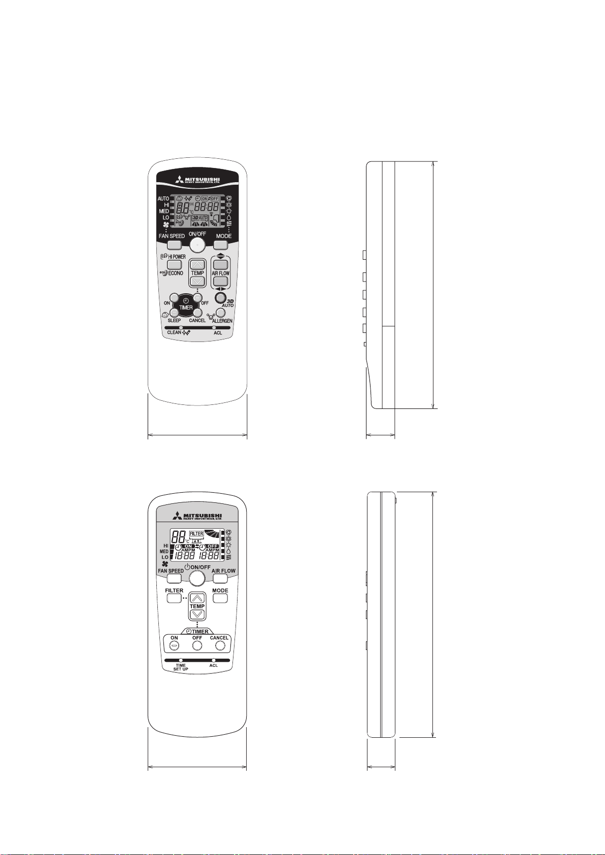
(3) Remote controller
60
17
150
Unit: mm
60
17.3
150
٨
The wireiess remote controller in the following figure shows for the SRK-50ZJ-S type.
(a) Wireless remote controller
Models SRK, SRF, SRR
'10 • SR-T-091D
Model FDTC (Option parts)
-
-
23
Page 25

-
24
-
'10 • SR-T-091D
(b) Wired remote controller (option parts)
TEMP ON/OFF
48
غ120
L C D
Wall surface
Wiring
Electrical box
䋨Not included䋩
19
Wiring specifications
Exposed mounting
23
46
11.5 11
Remote
control
outline
120
45
83.5
42
120
Remote control installation dimensions
Wiring oulet
Installation hole
12×7 Slot hole
9.5×5 Slot hole 䋨4places䋩
䋨1䋩 Installation screw for remote control
M4 Screw (2 pieces)
44
(1) If the prolongation is over 100m, change to the size below.
But, wiring in the remote controller case should be under 0.5mm2. Change the wire size outside of
the case according to wire connecting. Waterproof treatment is necessary at the wire connecting
section. Be careful about contact failure.
Length Wiring thickness
100 to 200m
0.5mm2×2 cores
0.75mm2×2 cores
1.25mm2×2 cores
2.0mm2×2 cores
Under 300m
Under 400m
Under 600m
Upper part
Lower part
Lower case
Sheath
Upper cace
Board
Wiring
Upper
Lower
X Y
Sheath
Upper cace
Board
Wiring
Upper
Lower
YX
Tighten the screws after
cutting off the thin part of
screw mounting part.
Embedded mounting
The peeling-off length of sheath
The peeling-off length
of sheath
In case of pulling out from
upper left
In case of pulling out
from upper left
In case of pulling out
from upper left
X wiring : 170mm
Y wiring : 190mm
Pulling out from center
X wiring : 215mm
Y wiring : 195mm
Pulling out from upper left
In case of pulling out from center
In case of pulling out
from center
In case of pulling out
from center
Wiring outlet
Cut off the upper thin part of remote control lower case with a nipper or knife,
and grind burrs with a file etc.
0.3mm2×2 cores.
X, Y Terminal block
Attach M3 screw
with washer
Unit:mm
PJZ0 0 0 Z274
Page 26

250V 3.15A
PRINTED
CNF CNE
CNX
CNG
4
CNU
1 3 65
35,50
CNY
M M M
5 5
U
2 8
2
t
o
CNS
CNM
M
5
TO OUTDOOR
S/N
J
L
G
1
CIRCUIT
BOARD
INTERFACE KIT
RDBKWHYBL
WIRELESS
DISPLAY
BACK-UP SW
UNIT
BK
WH
RD
Y/G
HEAT
EXCHANGER
2/N
3
Y/G
HD
ONLY
t
o
2
t
o
R-AMP
2
HEAT
EXCHANGER
5
FM
I
SM
I
LM
1
LM
2
F
Va
Th
I
Th
2
Th
3
T
DS
㨪
㨪
Blue
BlackBK
Red
BL
RD
WhiteWH
Yellow㧛GreenY㧛G
ColorMark
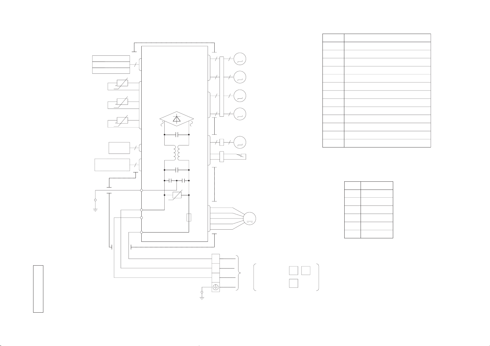
Heat exch. sensor
Fan motor
Room temp. sensor
Flap motor
Diode stackDS
FuseF
Connector
CNE-CNY
FM
I
Terminal blockT
Description
Item
VaristorVa
LM
1,2
SM
I
Louver motor
Th
I
Th
2,3
YellowY
Humidity sensor
HD
Power Source
1 Phase
220㧛230㧛240V 50Hz
-
25
3. ELECTRICAL WIRING
(1) Indoor units
(a) Wall mounted type (SRK)
Model SRK50ZJ-S
-
RWA000Z22 6
'10 • SR-T-091D
Page 27
-
26
-
'10 • SR-T-091D
Models SRK20ZJX-S, 25ZJX-S, 35ZJX-S, 50ZJX-S, 60ZJX-S
250V
F
G
3.15A
S㧛N
Va
CNU
CNS
INTERFACE KIT
SC-BIKN-E
CNG
CNE
DISPLAY
WIRELESS RECEIVER
J
CNF
U
M
HEAT
1
3
4
5
6
BACK-UP SW
5
2
12
EXCHANGER
L
Th1
BOARD
CIRCUIT
PRINTED
LS
CNY
CNX2
CNX1
M
M
M
M
M
5
5
5
5
5
5
5
5
5 5
IM
RD
WH
RD
WH
BK
BL
Y
Y㧛G
BK
t
Th2 1
Th2 2
Th3
LM
1
LM
2
SM
1
SM
2
FM
I
DS
t
t
TO OUTDOOR UNIT
HEAT
EXCHANGER
1
2㧛N
3
POWER WIRES
SIGNAL WIRE
1
2/N
3
Power source
1 phase 220 - 240 V 50Hz
T
Color Marks
Blue
BlackBK
Red
BL
RD
WhiteWH
Yellow㧛GreenY㧛G
YellowY
ColorMark
Heat exch. sensor
Humidity sensor 㧔50,60 only㧕
Fan motor
Room temp. sensor
Flap motor
Th1
Th2
Th3
Diode stackDS
FuseF
Connector
CNE-CNY
FM
I
Terminal blockT
Louver motor
LM
1,2
SM
1,2
1,2
Limit switchLS
Inlet motor
IM
Description
Item
VaristorVa
RWA000Z22 7
Page 28

(b) Floor standing type (SRF)
Color Marks
Blue
BlackBK
Red
BL
RD
WhiteWH
Yellow㧛GreenY㧛G
YellowYE
ColorMark
Heat exch. sensor
Humidity sensor
Fan motor
Room temp. sensor
Flap motor
Th1
Th2
Th3
Diode stackDS
FuseF
Connector
CNE-CNX2
FM
I
Terminal blockT
Damper motor
DM
1
SM
1,2
1,2
Damper arm motor
Description
Item
VaristorVa
DM
2
250V
F
G
3.15A
S㧛N
Va
CNU
CNS
INTERFACE KIT
SC-BIKN-E
CNG
CNE
DISPLAY
WIRELESS RECEIVER
J
CNF
U
M
HEAT
1
3
4
5
6
BACK-UP SW
5
2
10
EXCHANGER
L
Th1
BOARD
CIRCUIT
PRINTED
CNX2
CNX1
M
M
M
M
5
5
5
5
5
5
5
5
RD
WH
RD
WH
BK
BL
YE
Y㧛G
BK
t
Th2
1
Th2
2
Th3
DM
1
DM
2
SM
1
SM
2
FM
I
DS
t
t
TO OUTDOOR UNIT
HEAT
EXCHANGER
1
2㧛N
3
POWER WIRES
SIGNAL WIRE
1
2/N
3
Power source
1 phase 220 - 240 V 50Hz
T
AIR SELECTION SW
Models SRF25ZJX-S, 35ZJX-S, 50ZJX-S
-
27
-
RWB000Z0 52
'10 • SR-T-091D
Page 29

-
28
-
'10 • SR-T-091D
Item
Meaning of Marks
Description Item Description
Color Marks
Mark Color Mark Color
T
TO OUTDOOR UNIT
RECEIVER
BL
YE
BKRDWH
CNG
DISPLAY
WIRELESS
CNY
CNE
BK
BK
PRINTED CIRCUIT
BOARD
F
250V 3.15A
Va
CNU
1 3 54 6
G
Y㧛G
1
2/N
3
WH
BK
Y㧛G
RD
S㧛N
J
RD
BK
WH
BOX
CONTROL
U
8
2 2 2
RD
CNW
M
F
250V
0.16A
RD
OR
5
1㨪
WH
WH
BK
2
BK
10
BK
L
CNS
FM
DM
Th1
Th2 Th3
t
TO OUTDOOR UNIT
POWER WIRES
SIGNAL WIRE
1
2/N
3
Power source
1 phase 220 - 240 V 50Hz
BK
BL
OR
RD
YE
WH
Y㧛G
White
Yellow㧛Green
Black
Blue
Orange
Red
Yellow
ConnectorCNE-CNY
FM
DM
Fuse
Fan motor
Drain motor
Th2
Th3
Room temp. sensor
Heat exch. sensor 1
Heat exch. sensor 2
F
Th1
I
FS Float Switch
T Terminal block
Va Varistor
M
INTERFACE KIT
SC-BIKN-E
FS
t
t
(c) Ceiling concealed type (SRR)
Models SRR25ZJ-S, 35ZJ-S
RWA000Z23 0
Page 30

Control PCB
Power PCB
XR1
XR2
XR3
XR4
XR5(Remote operation input:volt-free contact)
Option
1
2
3
4
5
6
+12
SW2
SW6
SW5
SW7
LED・2 LED・3
X
Y
1
3
X
Y
t°
Remote controller
TB2
WH
BK
CNW3
RD
CNW2
RD
CNW4
BL
CNW1
BL
CNB
WH
CNN
Y
CNH
BK
CNI
BL
CNT
BL
1
2
WH
RD
F200(3.15A)
F201(3.15A)
F202
(1.0A)
F203
(0.16A)
X4
5
3
CNW0
WH
7
TB1
CNJ
WH
(Operation)
(Heating)
(CompressorON)
(Inspection)
Earth
Y/GN
Y/GN
Th
C
1 3
M
1〜
CNR
WH
DM
WH BR
Y Y
2 1
CNR2
BL
M
1 4 5 6 7
CNM
WH
FM
I
5 6 4 3 2
RD BL BR OR WH
RD BL BR OR WH
5 6 4 3 2
RD BL BR OR WH
CNM3
RD
CNM4
WH
BK
t°
BK
BK
t°
BK
1
2
1
2
BK
t°
BK
3
4
ThI-R2
ThI-R3
ThI-A
BL
BL
RD
RD
Y
Y
CNH2
WH
BK
t°
BK
5
6
ThI-R1
BK
BK
CNN2
BK
RD
RD
1
2
FS
WH
WH
CNI2
WH
3
4
5
6
7
8
9
10
1
2
1
2
3
4
5
6
1
2
1
2
BL
BL
RD
RD
Y
Y
BK
BK
WH
WH
CNC
WH
Power circuit
Y/GN
1
2
3
4
5
6
7
8
9
10
11
12
13
14
15
16
17
18
19
20
M
LM1
M
LM2
M
LM3
M
LM4
1
2
3
4
5
BK
BK
BK
BK
BK
CNJ2
WH
2
1
3
4
5
1
2
3
4
5
BL
BL
BL
BL
BL
1
2
3
4
5
RD
RD
RD
RD
RD
1
2
3
4
5
3
Power source line
Signal line
1 2
3
[ ]
indoor unit and outdoor unit
Connecting line between
BL
1
Y/GN
Y/GN
Y/GN
6
7
8
9
BK
BK
BK
BK
10
BK
11
BK
12
BK
13
BK
14
BK
15
BK
16
BK
17
BKBK
18
BK
19
BK
20
BK
1
2
3
4
5
BK
BK
BK
BK
BK
BK
BK
BK
BK
BK
BK
BK
BK
BK
BK
BK
BKBK
BK
BK
BK
1
2
3
4
5
1
2
3
4
5
1
2
3
4
5
I
FS
LM1〜4DM
FM
Float switch
Drain motor
Fan motor
Louver motor
Indication lamp(Red-Inspection)
Indication lamp
LED・3
F200〜203 Fuse
LED・2
ConnectorCNB〜Z
(Green-Normal operation)
Model capacity settingSW6
Operation check,Drain motor test runSW7-1
SW5
Thermistor(Remote controller)
Thermistor(Heat exchanger)
Thermistor(Return air)
Thc
ThI-R1,2,3
ThI-A
TB2 Terminal block(Signal line)(□mark)
Relay for DMX4
■ mark Closed-end connector
TB1 Terminal block(Power source)
(□ mark)
Remote controller communication
SW2
Orange
OR
BR Brown
BK Black
Blue
Color Marks
BL
Mark Color
RedRD
Y
Y/GN
WH
Yellow
Yellow/Green
White
Plural units Master/Slave setting
address
Notes 1. indicates wiring on site.
3. See the wiring diagram of outside unit about the line between
4. Use twin core cable(0.3mm X2)at remote controller line. See spec
sheet of remote controller in case that the total length is more than 100m.
5. Do not put remote controller line alongside power source line.
2
inside unit and outside unit.
2. TB1 is the terminal block for heavy current (connecting line between
and TB2 is the terminal block for weak current (remote controller).
indoor unit and outdoor unit),
(d) Ceiling cassette-4way compact type (FDTC)
Models FDTC25VD, 35VD
-
29
-
PJA 0 0 3Z340
B
'10 • SR-T-091D
Page 31

-
30
-
'10 • SR-T-091D
(2) Outdoor units
Color
RD
Mark
OrangeOR
Yellow/GreenY/G
BlackBK
BrownBR
YellowY
WhiteWH
Red
DescriptionItem
Connector
CNEEV~CN20S
Electric expansion valve(coil)
EEV
Fan motor
FMo
Reactor
L
Terminal block
T1,2
Compressor motor
CM
Solenoid valve for 4 way valve
20S
Heat exchanger sensor(outdoor unit)
TH1
Outdoor air temp.sensor
TH2
TH3
Discharge pipe temp.sensor
POWER SOURCE 1~220ー240V 50Hz/1~220V 60Hz
Model
Power cable, indoor-outdoor connecting wires
The specifications shown in the above table are for units without heaters. For units with heaters, refer
to the installation instructions or the construction instructions of the indoor unit.
Switchgear of Circuit breaker capacity which is calculated from MAX. over current should be chosen
along the regulations in each country.
The cable specifications are based on the assumption that a metal or plastic conduit is used with no
more than three cables contained in a conduit and a voltage drop is 2%. For an installation falling
outside of these conditions, please follow the internal cabling regulations. Adapt it to the regulation
in effect in each country.
14
2.0
18
φ1.6mm x 3 φ1.6mm
3
1
2
[ ]
N
50
M
T2
T1
S
(BK)
(WH)
(RD)
V
W
U
PWB ASSY (MAIN)
M
M
+ + +
R
TRANSISTOR
POWER
CIRCUIT
SWITCHING POWER
250V 2A
F1
250V 20A
F2
F3 250V 1A
W
V
U
P
NU
NV
NW
CNTH
CNEEV
CNFAN
t゜
3~
ACTIVE
FILTER
UNIT
250V 20A
F8
(OR)
(Y)
S-2
t゜ t゜
(BK)
(WH)
(WH)
(BK)
PWB ASSY (SUB)
S-1
CNSUB
CNMAIN
250V 10A
F10
S
R
R
(BK)
(WH)
G1
(Y/G)
(BR)
IN
IN
OUT
S
R
O
O
N
L
250V 20A
FUSE
2
1
N
3
(Y/G)
(Y/G)
CN20S
C-2
(RD)
20S
(RD)
T1
T2
TERMINAL
BLOCK
TH1 TH2 TH3
EEV
FMo
CM
BLOCK
TERMINAL
(WH)
TO INDOOR UNIT
POWER WIRES
SIGNAL WIRE
L
5 or 6 wires
MAX running current
Power cable size
(mm )
2
(A)
Power cable length
(m)
indoor-outdoor
wire size x number
Earth wire size
(mm)
Model SRC50ZJ-S
RWC000Z228
A
Page 32

Color
RD
Mark
OrangeOR
Yellow/GreenY/G
BlackBK
YellowY
WhiteWH
Red
DescriptionItem
Connector
Electric expansion valve(coil)
EEV
Fan motor
FMo
Reactor
L
Terminal block
T
Compressor motor
CM
Solenoid valve for 4 way valve
20S
Heat exchanger sensor(outdoor unit)
TH1
Outdoor air temp.sensor
TH2
TH3
Discharge pipe temp.sensor
CN20S
CNTH
CNEEV
CNFAN
20
Model
Power cable, indoor-outdoor connecting wires
The specifications shown in the above table are for units without heaters. For units with heaters, refer
to the installation instructions or the construction instructions of the indoor unit.
Switchgear of Circuit breaker capacity which is calculated from MAX. over current should be chosen
along the regulations in each country.
The cable specifications are based on the assumption that a metal or plastic conduit is used with no
more than three cables contained in a conduit and a voltage drop is 2%. For an installation falling
outside of these conditions, please follow the internal cabling regulations. Adapt it to the regulation
in effect in each country.
25 8 2.0 32
φ1.6mm x 3 φ1.6mm
35
3
1
2
[ ]
N
~220ー240V 50Hz/~220V 60Hz
POWER SOURCE
(BK)
C-2
G1
(RD)
(Y/G)
S.IN(WH)
R.IN
(BK)
(WH)
(RD)
PWB ASSY
250V 20A
F2
F3 250V 1A
+ +
F4
250V 10A
F1
250V 2A
CIRCUIT
PAM
SWITCHING POWER
CIRCUIT
N
P
W
V
U
TRANSISTOR
POWER
W
V
U
FILTER
NOISE
CN20S
CNTH
CNEEV
CNFAN
M
M
3~
250V 15A
(Y/G)
T1
T2
(OR)
(Y)
M
t゜
TH1 TH2 TH3
EEV
FMo
CM
t゜ t゜
t゜
5 or 6 wires
TERMINAL
LN1
3
2
BLOCK
T
TO INDOOR UNIT
POWER WIRES
SIGNAL WIRE
20S
L
MAX running current
Power cable size
(mm )
2
(A)
Power cable length
(m)
indoor-outdoor
wire size x number
Earth wire size
(mm)
-
31
-
Models SRC20ZJX-S, 25ZJX-S, 35ZJX-S
RWC000Z227
A
'10 • SR-T-091D
Page 33

Color
RD
Mark
OrangeOR
Yellow/GreenY/G
BlackBK
BrownBR
YellowY
WhiteWH
Red
DescriptionItem
Connector
CNEEV~20S
Electric expansion valve(coil)
EEV
Fan motor
FMo
Reactor
L
Terminal block
T1,2
Compressor motor
CM
Solenoid valve for 4 way valve
20S
Heat exchanger sensor(outdoor unit)
TH1
Outdoor air temp.sensor
TH2
TH3
Discharge pipe temp.sensor
POWER SOURCE 1~220ー240V 50Hz/1~220V 60Hz
Model
Power cable, indoor-outdoor connecting wires
The specifications shown in the above table are for units without heaters. For units with heaters, refer
to the installation instructions or the construction instructions of the indoor unit.
Switchgear of Circuit breaker capacity which is calculated from MAX. over current should be chosen
along the regulations in each country.
The cable specifications are based on the assumption that a metal or plastic conduit is used with no
more than three cables contained in a conduit and a voltage drop is 2%. For an installation falling
outside of these conditions, please follow the internal cabling regulations. Adapt it to the regulation
in effect in each country.
40
14
2.0
18
φ1.6mm x 3 φ1.6mm50
3
1
2
[ ]
N
60
12 21
M
T2
T1
S
(BK)
(WH)
(RD)
V
W
U
PWB ASSY (MAIN)
M
M
+ + +
R
TRANSISTOR
POWER
CIRCUIT
SWITCHING POWER
250V 2A
F1
250V 20A
F2
F3 250V 1A
W
V
U
P
NU
NV
NW
CNTH
CNEEV
CNFAN
t゜
3~
ACTIVE
FILTER
UNIT
250V 20A
F8
(OR)
(Y)
S-2
t゜ t゜
(BK)
(WH)
(WH)
(BK)
PWB ASSY (SUB)
S-1
CNSUB
CNMAIN
250V 10A
F10
S
R
R
(BK)
(WH)
G1
(Y/G)
(BR)
IN
IN
OUT
S
R
O
O
N
L
250V 20A
FUSE
2
1
N
3
(Y/G)
(Y/G)
CN20S
C-2
(RD)
20S
(RD)
T1
T2
TERMINAL
BLOCK
TH1 TH2 TH3
EEV
FMo
CM
BLOCK
TERMINAL
(WH)
TO INDOOR UNIT
POWER WIRES
SIGNAL WIRE
L
5 or 6 wires
MAX running current
Power cable size
(mm )
2
(A)
Power cable length
(m)
indoor-outdoor
wire size x number
Earth wire size
(mm)
Models SRC50ZIX-S, 60ZIX-S
-
32
-
RWC000Z214
A
'10 • SR-T-091D
Page 34

INVERTER RESIDENTIAL AIR CONDITIONERS
Air-Conditioning & Refrigeration Systems Headquarters
16-5, 2-chome, Kounan, Minato-ku, Tokyo, 108-8215, Japan
Fax : (03) 6716-5926
Copyright MITSUBISHI HEAVY INDUSTRIES, LTD.
Because of our policy of continuous improvement, we reserve the right to make changes in all specifications without notice.
C
 Loading...