

Mitsubishi Electric SRK05CR-S, SRK05CRP-S, SRK12CR-S, SRK09CR-S, SRK09CRP-S Technical Manual
...Page 1

RESIDENTIAL AIR-CONDITIONING
TECHNICAL MANUAL & PARTS LIST
WALL MOUNTED TYPE
RESIDENTIAL AIR-CONDITIONERS
(Split system, air cooled cooling only type)
SRK05CR-S, S3, S6
SRK05CRP-S, S3
SRK09CR-S, S3, S4, S5
SRK09CRP-S, S3, S5
SRK09CRR-S, S3, S4, S5, S6
SRK12CR-S, S3, S4, S5, S6
Manual No.'15•SRK-T-171
Page 2

Page 3
-
1
-
'15 • SRK-T-171
TECHNICAL MANUAL
Page 4

-
2
-
'15 • SRK-T-171
'10 • SRK-T-099
CONTENTS
1. SPECIFICATIONS .................................................................................... 4
(2) Outdoor units ...................................................................................... 28
(3) Wireless remote control
...................................................................... 30
........................................................................ 26
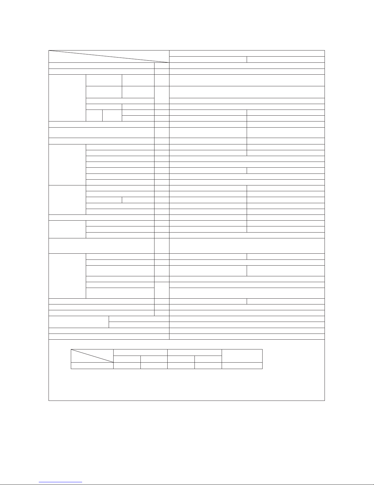
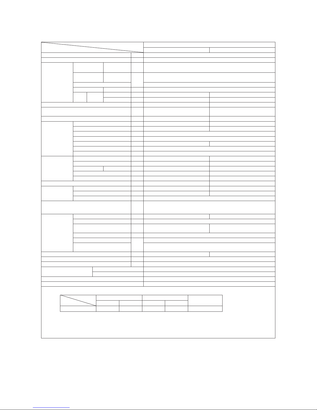
(1) Indoor units ......................................................................................... 26
2. EXTERIOR DIMENSIONS
3. ELECTRICAL WIRING ............................................................................. 31
(1) Indoor units ......................................................................................... 31
(2) Outdoor units ...................................................................................... 32
....................................................... 41
6. RANGE OF USAGE & LIMITATIONS
5. PIPING SYSTEM ..................................................................................... 40
4. NOISE LEVEL ..................................................................................... 34
7. CAPACITY TABLES
............................................................................... 46
............................................................................... 43
8. APPLICATION DATA
9. OUTLINE OF OPERATION CONTROL BY MICROCOMPUTER ........... 56
(6) Timer operation
................................................................................. 59
(5) Flap control ....................................................................................... 59
...................................................... 58(4) Custom cord switching procedure
........................................................................ 58(3) Auto restart function
(2) Unit ON/OFF button
.......................................................................... 58
(1) Operation control function by remote control
..................................... 56
(8) Outline of automatic operation .......................................................... 60
(7) Outline of cooling operation .............................................................. 60
(9) Protective control function
.................................................................. 61
.............................................................................. 62
.................... 63
(4) Troubleshooting procedure (If the air-conditioner runs)
(3) Troubleshooting procedure
(If the air-conditioner does not run at all)
....... 62
(1) Cautions
............................................................................................ 62
(2) Items to check before troubleshooting ................................................ 62
(5) Self-diagnosis table ............................................................................ 63
(6) Inspection procedures corresponding to detail of trouble ................... 64
10. MAINTENANCE DATA
Page 5

-
3
-
'15 • SRK-T-171
'10 • SRK-T-099
(7)
Phenomenon observed after shortcircuit, wire breakage on sensor
........ 65
■How to read the model name
Example: SRK 05 C
Series code
Cooling only type
Product capacity
Model name SRK : Wall mounted type
SRC : Outdoor unit
R-S
(8) How to make sure of wireless remote control ..................................... 66
Page 6
-
4
-
'15 • SRK-T-171
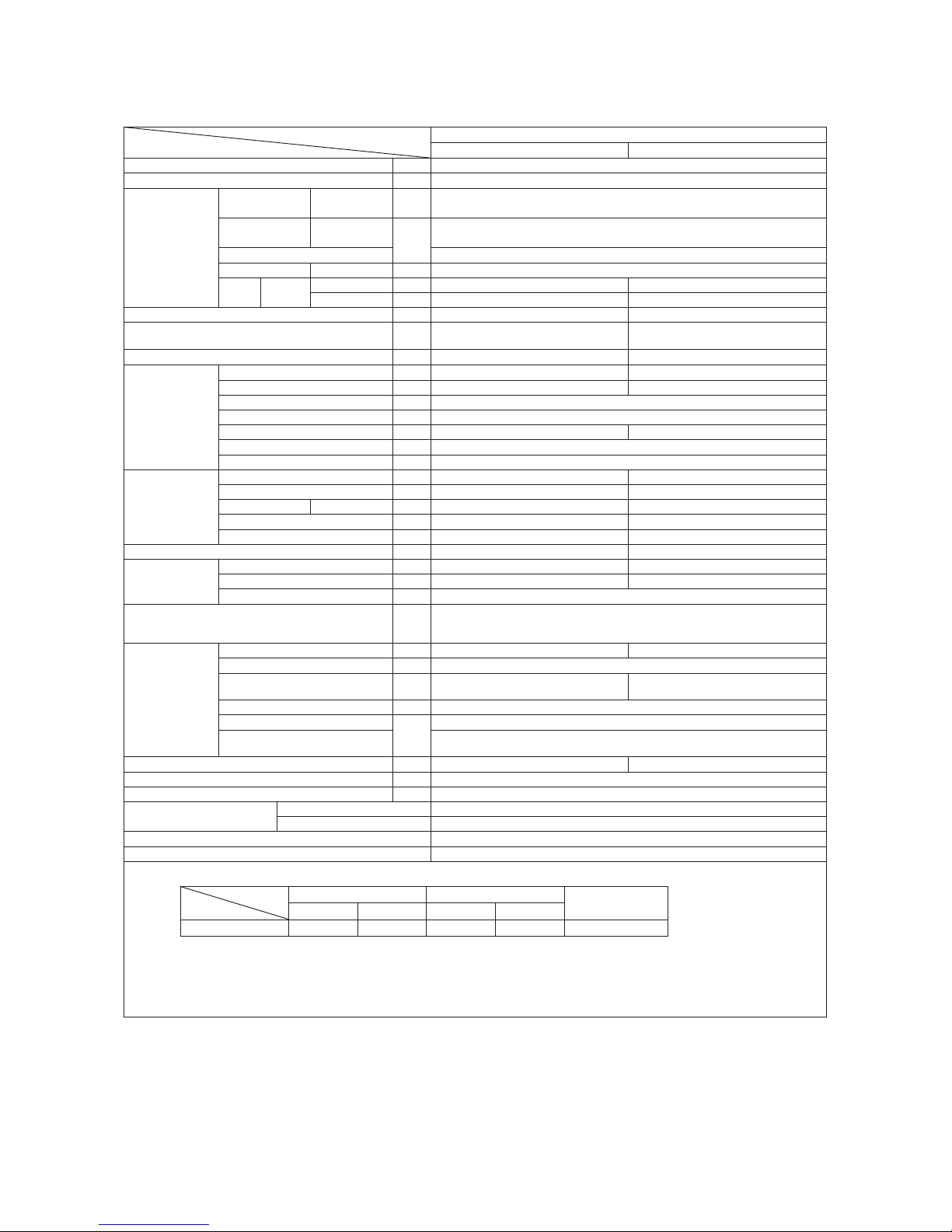
1. SPECIFICATIONS
Model
Item
SRK05CR-S
Indoor unit SRK05CR-S Outdoor unit SRC05CR-S
Cooling capacity (1) W 1465
Power source 1 Phase, 220-240V, 50Hz
Operation
data
Power
consumption
Cooling kW 0.375
Running
current
Cooling
A
1.70
Inrush current 10
COP Cooling 3.91
Noise
level
Cooling
Sound level dB(A) 42 48
Power level dB 56 59
Exterior dimensions (Height x Width x Depth) mm 262 x 615 x 210 435 x 645 (+50) x 275
Exterior appearance
(Munsell color)
Fine snow
(8.0Y 9.3/0.1) near equivalent
Stucco white
(4.2Y 7.5/1.1) near equivalent
Net weight kg 6 20
Refrigerant
equipment
Compressor type & Q'ty — GAB046PAA (Rotary type) x 1
Motor (Starting method) kW — PSC
Refrigerant oil
ℓ
0.23 (POE [RB68A] or PVE [FVC68D])
Refrigerant (4) kg R410A 0.46 ( Pre-charged up to the piping length of 5m )
Heat exchanger Louver fins & inner grooved tubing Louver fins & inner grooved tubing
Refrigerant control Capillary tubes
Device control Microcomputer control
Air handling
equipment
Fan type & Q'ty Cross flow fan x 1 Propeller fan x 1
Motor W 17 22
Air flow Cooling m3/min 8.5 23
Fresh air intake Not possible —
Air filter, Quality / Quantity Polypropylene net (washable) x 1 —
Shock & vibration absorber — Cushion rubber (for compressor)
Operation
control
Operation switch Wireless remote control —
Room temperature control Microcomputer thermostat —
Operation display RUN : Green, TIMER : Yellow
Safety devices
Compressor overheat protection, Overcurrent protection,
Frost protection, Serial signal error protection, Indoor Fan motor error protection,
Cooling overload protection
Installation
data
Refrigerant piping size (O.D) mm Liquid line: φ6.35 (1/4") Gas line: φ9.52 (3/8")
Connecting method Flare connecting
Attached length of piping m
Liquid line : 0.46
Gas line : 0.40
—
Insulation for piping Necessary (Both sides), independent
Refrigerant line (one way) length
m
Max. 15
Vertical height difference between
outdoor unit and indoor unit
Max.5 (Outdoor unit is higher)
Max.5 (Outdoor unit is lower)
Drain hose Connectable (VP 16) —
Power cable —
Recommended breaker size A 10
Connection wiring
Size x Core number 1.5mm2 x 3 cores (Including earth cable)
Connecting method Terminal block (Screw fixing type)
Accessories (included) Mounting kit
Option parts —
Note (1) The data are measured at the following conditions.
Item
Operation
Indoor air temperature Outdoor air temperature
Standards
DB WB DB WB
Cooling 27˚C 19˚C 35˚C 24˚C ISO-T1, JIS C 9612
(2) This air-conditioner is manufactured and tested in conformity with the ISO.
(3) The operation data are applied to the 220V districts respectively.
(4) The refrigerant quantity to be charged includes the refrigerant in 5m connecting piping.
(Purging is not required even for the short piping.)
If the piping length is 5m to 15m, additional refrigerant is 10g per each 1m longer than 5m.
The pipe length is 5m.
Page 7

-
5
-
'15 • SRK-T-171
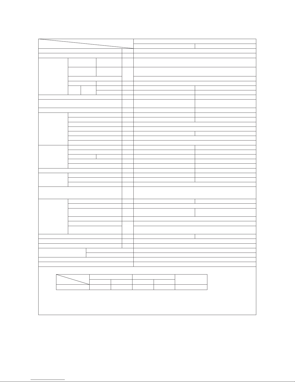
Model
Item
SRK05CR-S3
Indoor unit SRK05CR-S3 Outdoor unit SRC05CR-S3
Cooling capacity (1) W 1465
Power source 1 Phase, 220-240V, 50Hz
Operation
data
Power
consumption
Cooling kW 0.375
Running
current
Cooling
A
1.70
Inrush current 10
COP Cooling 3.91
Noise
level
Cooling
Sound level dB(A) 42 48
Power level dB 56 59
Exterior dimensions (Height x Width x Depth) mm 262 x 615 x 210 435 x 645 (+50) x 275
Exterior appearance
(Munsell color)
Fine snow
(8.0Y 9.3/0.1) near equivalent
Stucco white
(4.2Y 7.5/1.1) near equivalent
Net weight kg 6 20
Refrigerant
equipment
Compressor type & Q'ty — GAB046PAA (Rotary type) x 1
Motor (Starting method) kW — PSC
Refrigerant oil
ℓ
0.23 (POE [RB68A] or PVE [FVC68D])
Refrigerant (4) kg R410A 0.46 ( Pre-charged up to the piping length of 5m )
Heat exchanger Louver fins & inner grooved tubing Louver fins & inner grooved tubing
Refrigerant control Capillary tubes
Device control Microcomputer control
Air handling
equipment
Fan type & Q'ty Cross flow fan x 1 Propeller fan x 1
Motor W 17 22
Air flow Cooling m3/min 8.5 23
Fresh air intake Not possible —
Air filter, Quality / Quantity Polypropylene net (washable) x 1 —
Shock & vibration absorber — Cushion rubber (for compressor)
Operation
control
Operation switch Wireless remote control —
Room temperature control Microcomputer thermostat —
Operation display RUN : Green, TIMER : Yellow
Safety devices
Compressor overheat protection, Overcurrent protection,
Frost protection, Serial signal error protection, Indoor fan motor error protection,
Cooling overload protection
Installation
data
Refrigerant piping size (O.D) mm Liquid line: φ6.35 (1/4") Gas line: φ9.52 (3/8")
Connecting method Flare connecting
Attached length of piping m
Liquid line : 0.46
Gas line : 0.40
—
Insulation for piping Necessary (Both sides), independent
Refrigerant line (one way) length
m
Max. 15
Vertical height difference between
outdoor unit and indoor unit
Max.5 (Outdoor unit is higher)
Max.5 (Outdoor unit is lower)
Drain hose Connectable (VP 16) —
Power cable —
Recommended breaker size A 10
Connection wiring
Size x Core number 1.5mm2 x 3 cores (Including earth cable)
Connecting method Terminal block (Screw fixing type)
Accessories (included) Mounting kit
Option parts —
Note (1) The data are measured at the following conditions.
Item
Operation
Indoor air temperature Outdoor air temperature
Standards
DB WB DB WB
Cooling 27˚C 19˚C 35˚C 24˚C ISO-T1, JIS C 9612
(2) This air-conditioner is manufactured and tested in conformity with the ISO.
(3) The operation data are applied to the 220V districts respectively.
(4) The refrigerant quantity to be charged includes the refrigerant in 5m connecting piping.
(Purging is not required even for the short piping.)
If the piping length is 5m to 15m, additional refrigerant is 10g per each 1m longer than 5m.
The pipe length is 5m.
Page 8
-
6
-
'15 • SRK-T-171
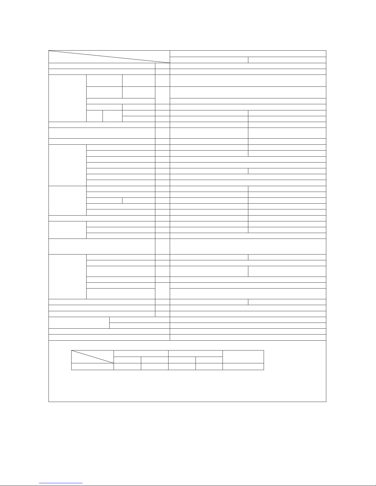
Model
Item
SRK05CR-S6
Indoor unit SRK05CR-S6 Outdoor unit SRC05CR-S6
Cooling capacity (1) W 1465
Power source 1 Phase, 220-240V, 50Hz
Operation
data
Power
consumption
Cooling kW 0.400
Running
current
Cooling
A
1.80
Inrush current 10
COP Cooling 3.66
Noise
level
Cooling
Sound level dB(A) 42 50
Power level dB 56 61
Exterior dimensions (Height x Width x Depth) mm 262 x 615 x 210 435 x 645 (+50) x 275
Exterior appearance
(Munsell color)
Fine snow
(8.0Y 9.3/0.1) near equivalent
Stucco white
(4.2Y 7.5/1.1) near equivalent
Net weight kg 6 20
Refrigerant
equipment
Compressor type & Q'ty — GAB046PAA (Rotary type) x 1
Motor (Starting method) kW — PSC
Refrigerant oil
ℓ
0.23 (POE [RB68A] or PVE [FVC68D])
Refrigerant (4) kg R410A 0.46 ( Pre-charged up to the piping length of 5m )
Heat exchanger Louver fins & inner grooved tubing Louver fins & inner grooved tubing
Refrigerant control Capillary tubes
Device control Microcomputer control
Air handling
equipment
Fan type & Q'ty Cross flow fan x 1 Propeller fan x 1
Motor W 17 22
Air flow Cooling m3/min 8.5 23
Fresh air intake Not possible —
Air filter, Quality / Quantity Polypropylene net (washable) x 1 —
Shock & vibration absorber — Cushion rubber (for compressor)
Operation
control
Operation switch Wireless remote control —
Room temperature control Microcomputer thermostat —
Operation display RUN : Green, TIMER : Yellow
Safety devices
Compressor overheat protection, Overcurrent protection,
Frost protection, Serial signal error protection, Indoor Fan motor error protection,
Cooling overload protection
Installation
data
Refrigerant piping size (O.D) mm Liquid line: φ6.35 (1/4") Gas line: φ9.52 (3/8")
Connecting method Flare connecting
Attached length of piping m
Liquid line : 0.46
Gas line : 0.40
—
Insulation for piping Necessary (Both sides), independent
Refrigerant line (one way) length
m
Max. 15
Vertical height difference between
outdoor unit and indoor unit
Max.5 (Outdoor unit is higher)
Max.5 (Outdoor unit is lower)
Drain hose Connectable (VP 16) —
Power cable —
Recommended breaker size A 10
Connection wiring
Size x Core number 1.5mm2 x 3 cores (Including earth cable)
Connecting method Terminal block (Screw fixing type)
Accessories (included) Mounting kit
Option parts —
Note (1) The data are measured at the following conditions.
Item
Operation
Indoor air temperature Outdoor air temperature
Standards
DB WB DB WB
Cooling 27˚C 19˚C 35˚C 24˚C ISO-T1, JIS C 9612
(2) This air-conditioner is manufactured and tested in conformity with the ISO.
(3) The operation data are applied to the 230V districts respectively.
(4) The refrigerant quantity to be charged includes the refrigerant in 5m connecting piping.
(Purging is not required even for the short piping.)
If the piping length is 5m to 15m, additional refrigerant is 10g per each 1m longer than 5m.
The pipe length is 5m.
Page 9

-
7
-
'15 • SRK-T-171
Model
Item
SRK05CRP-S
Indoor unit SRK05CRP-S Outdoor unit SRC05CRP-S
Cooling capacity (1) W 1465
Power source 1 Phase, 220-240V, 50Hz
Operation
data
Power
consumption
Cooling kW 0.490
Running
current
Cooling
A
2.30
Inrush current 10
COP Cooling 2.99
Noise
level
Cooling
Sound level dB(A) 42 50
Power level dB 56 61
Exterior dimensions (Height x Width x Depth) mm 262 x 615 x 210 435 x 645 (+50) x 275
Exterior appearance
(Munsell color)
Fine snow
(8.0Y 9.3/0.1) near equivalent
Stucco white
(4.2Y 7.5/1.1) near equivalent
Net weight kg 6 19.5
Refrigerant
equipment
Compressor type & Q'ty — GAB046PAA (Rotary type) x 1
Motor (Starting method) kW — PSC
Refrigerant oil
ℓ
0.23 (POE [RB68A] or PVE [FVC68D])
Refrigerant (4) kg R410A 0.44 ( Pre-charged up to the piping length of 5m )
Heat exchanger Louver fins & inner grooved tubing Louver fins & inner grooved tubing
Refrigerant control Capillary tubes
Device control Microcomputer control
Air handling
equipment
Fan type & Q'ty Cross flow fan x 1 Propeller fan x 1
Motor W 17 22
Air flow Cooling m3/min 8.5 20
Fresh air intake Not possible —
Air filter, Quality / Quantity Polypropylene net (washable) x 1 —
Shock & vibration absorber — Cushion rubber (for compressor)
Operation
control
Operation switch Wireless remote control —
Room temperature control Microcomputer thermostat —
Operation display RUN : Green, TIMER : Yellow
Safety devices
Compressor overheat protection, Overcurrent protection,
Frost protection, Serial signal error protection, Indoor Fan motor error protection,
Cooling overload protection
Installation
data
Refrigerant piping size (O.D) mm Liquid line: φ6.35 (1/4") Gas line: φ9.52 (3/8")
Connecting method Flare connecting
Attached length of piping m
Liquid line : 0.46
Gas line : 0.40
—
Insulation for piping Necessary (Both sides), independent
Refrigerant line (one way) length
m
Max. 15
Vertical height difference between
outdoor unit and indoor unit
Max.5 (Outdoor unit is higher)
Max.5 (Outdoor unit is lower)
Drain hose Connectable (VP 16) —
Power cable —
Recommended breaker size A 10
Connection wiring
Size x Core number 1.5mm2 x 3 cores (Including earth cable)
Connecting method Terminal block (Screw fixing type)
Accessories (included) Mounting kit
Option parts —
Note (1) The data are measured at the following conditions.
Item
Operation
Indoor air temperature Outdoor air temperature
Standards
DB WB DB WB
Cooling 27˚C 19˚C 35˚C 24˚C ISO-T1, JIS C 9612
(2) This air-conditioner is manufactured and tested in conformity with the ISO.
(3) The operation data are applied to the 220V districts respectively.
(4) The refrigerant quantity to be charged includes the refrigerant in 5m connecting piping.
(Purging is not required even for the short piping.)
If the piping length is 5m to 15m, additional refrigerant is 10g per each 1m longer than 5m.
The pipe length is 5m.
Page 10

-
8
-
'15 • SRK-T-171
Model
Item
SRK05CRP-S3
Indoor unit SRK05CRP-S3 Outdoor unit SRC05CRP-S3
Cooling capacity (1) W 1465
Power source 1 Phase, 220-240V, 50Hz
Operation
data
Power
consumption
Cooling kW 0.490
Running
current
Cooling
A
2.30
Inrush current 10
COP Cooling 2.99
Noise
level
Cooling
Sound level dB(A) 42 50
Power level dB 56 61
Exterior dimensions (Height x Width x Depth) mm 262 x 615 x 210 435 x 645 (+50) x 275
Exterior appearance
(Munsell color)
Fine snow
(8.0Y 9.3/0.1) near equivalent
Stucco white
(4.2Y 7.5/1.1) near equivalent
Net weight kg 6 19.5
Refrigerant
equipment
Compressor type & Q'ty — GAB046PAA (Rotary type) x 1
Motor (Starting method) kW — PSC
Refrigerant oil
ℓ
0.23 (POE [RB68A] or PVE [FVC68D])
Refrigerant (4) kg R410A 0.44 ( Pre-charged up to the piping length of 5m )
Heat exchanger Louver fins & inner grooved tubing Louver fins & inner grooved tubing
Refrigerant control Capillary tubes
Device control Microcomputer control
Air handling
equipment
Fan type & Q'ty Cross flow fan x 1 Propeller fan x 1
Motor W 17 22
Air flow Cooling m3/min 8.5 20
Fresh air intake Not possible —
Air filter, Quality / Quantity Polypropylene net (washable) x 1 —
Shock & vibration absorber — Cushion rubber (for compressor)
Operation
control
Operation switch Wireless remote control —
Room temperature control Microcomputer thermostat —
Operation display RUN : Green, TIMER : Yellow
Safety devices
Compressor overheat protection, Overcurrent protection,
Frost protection, Serial signal error protection, Indoor Fan motor error protection,
Cooling overload protection
Installation
data
Refrigerant piping size (O.D) mm Liquid line: φ6.35 (1/4") Gas line: φ9.52 (3/8")
Connecting method Flare connecting
Attached length of piping m
Liquid line : 0.46
Gas line : 0.40
—
Insulation for piping Necessary (Both sides), independent
Refrigerant line (one way) length
m
Max. 15
Vertical height difference between
outdoor unit and indoor unit
Max.5 (Outdoor unit is higher)
Max.5 (Outdoor unit is lower)
Drain hose Connectable (VP 16) —
Power cable —
Recommended breaker size A 10
Connection wiring
Size x Core number 1.5mm2 x 3 cores (Including earth cable)
Connecting method Terminal block (Screw fixing type)
Accessories (included) Mounting kit
Option parts —
Note (1) The data are measured at the following conditions.
Item
Operation
Indoor air temperature Outdoor air temperature
Standards
DB WB DB WB
Cooling 27˚C 19˚C 35˚C 24˚C ISO-T1, JIS C 9612
(2) This air-conditioner is manufactured and tested in conformity with the ISO.
(3) The operation data are applied to the 220V districts respectively.
(4) The refrigerant quantity to be charged includes the refrigerant in 5m connecting piping.
(Purging is not required even for the short piping.)
If the piping length is 5m to 15m, additional refrigerant is 10g per each 1m longer than 5m.
The pipe length is 5m.
Page 11

-
9
-
'15 • SRK-T-171
Model
Item
SRK09CR-S
Indoor unit SRK09CR-S Outdoor unit SRC09CR-S
Cooling capacity (1) W 2500
Power source 1 Phase, 220-240V, 50Hz
Operation
data
Power
consumption
Cooling kW 0.893
Running
current
Cooling
A
4.1 / 3.9
Inrush current 15
COP Cooling 2.80
Noise
level
Cooling
Sound level dB(A) 43 50
Power level dB 57 61
Exterior dimensions (Height x Width x Depth) mm 262 x 615 x 210 435 x 645 (+50) x 275
Exterior appearance
(Munsell color)
Fine snow
(8.0Y 9.3/0.1) near equivalent
Stucco white
(4.2Y 7.5/1.1) near equivalent
Net weight kg 6 24.5
Refrigerant
equipment
Compressor type & Q'ty — GKS102PAB (Rotary type) x 1
Motor (Starting method) kW — PSC
Refrigerant oil
ℓ
0.30 (POE [RB68A] or PVE [FVC68D])
Refrigerant (4) kg R410A 0.52 ( Pre-charged up to the piping length of 5m )
Heat exchanger Louver fins & inner grooved tubing Louver fins & inner grooved tubing
Refrigerant control Capillary tubes
Device control Microcomputer control
Air handling
equipment
Fan type & Q'ty Cross flow fan x 1 Propeller fan x 1
Motor W 17 22
Air flow Cooling m3/min 9 23
Fresh air intake Not possible —
Air filter, Quality / Quantity Polypropylene net (washable) x 1 —
Shock & vibration absorber — Cushion rubber (for compressor)
Operation
control
Operation switch Wireless remote control —
Room temperature control Microcomputer thermostat —
Operation display RUN : Green, TIMER : Yellow
Safety devices
Compressor overheat protection, Overcurrent protection,
Frost protection, Serial signal error protection, Indoor Fan motor error protection,
Cooling overload protection
Installation
data
Refrigerant piping size (O.D) mm Liquid line: φ6.35 (1/4") Gas line: φ9.52 (3/8")
Connecting method Flare connecting
Attached length of piping m
Liquid line : 0.46
Gas line : 0.40
—
Insulation for piping Necessary (Both sides), independent
Refrigerant line (one way) length
m
Max. 15
Vertical height difference between
outdoor unit and indoor unit
Max.5 (Outdoor unit is higher)
Max.5 (Outdoor unit is lower)
Drain hose Connectable (VP 16) —
Power cable —
Recommended breaker size A 10
Connection wiring
Size x Core number 1.5mm2 x 3 cores (Including earth cable)
Connecting method Terminal block (Screw fixing type)
Accessories (included) Mounting kit
Option parts —
Note (1) The data are measured at the following conditions.
Item
Operation
Indoor air temperature Outdoor air temperature
Standards
DB WB DB WB
Cooling 27˚C 19˚C 35˚C 24˚C ISO-T1, JIS C 9612
(2) This air-conditioner is manufactured and tested in conformity with the ISO.
(3) The operation data are applied to the 220/230V districts respectively.
(4) The refrigerant quantity to be charged includes the refrigerant in 5m connecting piping.
(Purging is not required even for the short piping.)
If the piping length is 5m to 15m, additional refrigerant is 10g per each 1m longer than 5m.
The pipe length is 5m.
Page 12
-
10
-
'15 • SRK-T-171
Model
Item
SRK09CR-S3
Indoor unit SRK09CR-S3 Outdoor unit SRC09CR-S3
Cooling capacity (1) W 2500
Power source 1 Phase, 220-240V, 50Hz
Operation
data
Power
consumption
Cooling kW 0.893
Running
current
Cooling
A
4.1 / 3.9
Inrush current 15
COP Cooling 2.80
Noise
level
Cooling
Sound level dB(A) 43 50
Power level dB 57 61
Exterior dimensions (Height x Width x Depth) mm 262 x 615 x 210 435 x 645 (+50) x 275
Exterior appearance
(Munsell color)
Fine snow
(8.0Y 9.3/0.1) near equivalent
Stucco white
(4.2Y 7.5/1.1) near equivalent
Net weight kg 6 24.5
Refrigerant
equipment
Compressor type & Q'ty — GKS102PAB (Rotary type) x 1
Motor (Starting method) kW — PSC
Refrigerant oil
ℓ
0.30 (POE [RB68A] or PVE [FVC68D])
Refrigerant (4) kg R410A 0.52 ( Pre-charged up to the piping length of 5m )
Heat exchanger Louver fins & inner grooved tubing Louver fins & inner grooved tubing
Refrigerant control Capillary tubes
Device control Microcomputer control
Air handling
equipment
Fan type & Q'ty Cross flow fan x 1 Propeller fan x 1
Motor W 17 22
Air flow Cooling m3/min 9 23
Fresh air intake Not possible —
Air filter, Quality / Quantity Polypropylene net (washable) x 1 —
Shock & vibration absorber — Cushion rubber (for compressor)
Operation
control
Operation switch Wireless remote control —
Room temperature control Microcomputer thermostat —
Operation display RUN : Green, TIMER : Yellow
Safety devices
Compressor overheat protection, Overcurrent protection,
Frost protection, Serial signal error protection, Indoor Fan motor error protection,
Cooling overload protection
Installation
data
Refrigerant piping size (O.D) mm Liquid line: φ6.35 (1/4") Gas line: φ9.52 (3/8")
Connecting method Flare connecting
Attached length of piping m
Liquid line : 0.46
Gas line : 0.40
—
Insulation for piping Necessary (Both sides), independent
Refrigerant line (one way) length
m
Max. 15
Vertical height difference between
outdoor unit and indoor unit
Max.5 (Outdoor unit is higher)
Max.5 (Outdoor unit is lower)
Drain hose Connectable (VP 16) —
Power cable —
Recommended breaker size A 10
Connection wiring
Size x Core number 1.5mm2 x 3 cores (Including earth cable)
Connecting method Terminal block (Screw fixing type)
Accessories (included) Mounting kit
Option parts —
Note (1) The data are measured at the following conditions.
Item
Operation
Indoor air temperature Outdoor air temperature
Standards
DB WB DB WB
Cooling 27˚C 19˚C 35˚C 24˚C ISO-T1, JIS C 9612
(2) This air-conditioner is manufactured and tested in conformity with the ISO.
(3) The operation data are applied to the 220/230V districts respectively.
(4) The refrigerant quantity to be charged includes the refrigerant in 5m connecting piping.
(Purging is not required even for the short piping.)
If the piping length is 5m to 15m, additional refrigerant is 10g per each 1m longer than 5m.
The pipe length is 5m.
Page 13

-
11
-
'15 • SRK-T-171
Model
Item
SRK09CR-S4
Indoor unit SRK09CR-S4 Outdoor unit SRC09CR-S4
Cooling capacity (1) W 2500
Power source 1 Phase, 220-240V, 50Hz
Operation
data
Power
consumption
Cooling kW 0.893
Running
current
Cooling
A
4.1 / 3.9
Inrush current 15
COP Cooling 2.80
Noise
level
Cooling
Sound level dB(A) 43 50
Power level dB 57 61
Exterior dimensions (Height x Width x Depth) mm 262 x 615 x 210 435 x 645 (+50) x 275
Exterior appearance
(Munsell color)
Fine snow
(8.0Y 9.3/0.1) near equivalent
Stucco white
(4.2Y 7.5/1.1) near equivalent
Net weight kg 6 24.5
Refrigerant
equipment
Compressor type & Q'ty — GKS102PAB (Rotary type) x 1
Motor (Starting method) kW — PSC
Refrigerant oil
ℓ
0.30 (POE [RB68A] or PVE [FVC68D])
Refrigerant (4) kg R410A 0.52 ( Pre-charged up to the piping length of 5m )
Heat exchanger Louver fins & inner grooved tubing Louver fins & inner grooved tubing
Refrigerant control Capillary tubes
Device control Microcomputer control
Air handling
equipment
Fan type & Q'ty Cross flow fan x 1 Propeller fan x 1
Motor W 17 22
Air flow Cooling m3/min 9 23
Fresh air intake Not possible —
Air filter, Quality / Quantity Polypropylene net (washable) x 1 —
Shock & vibration absorber — Cushion rubber (for compressor)
Operation
control
Operation switch Wireless remote control —
Room temperature control Microcomputer thermostat —
Operation display RUN : Green, TIMER : Yellow
Safety devices
Compressor overheat protection, Overcurrent protection,
Frost protection, Serial signal error protection, Indoor Fan motor error protection,
Cooling overload protection
Installation
data
Refrigerant piping size (O.D) mm Liquid line: φ6.35 (1/4") Gas line: φ9.52 (3/8")
Connecting method Flare connecting
Attached length of piping m
Liquid line : 0.46
Gas line : 0.40
—
Insulation for piping Necessary (Both sides), independent
Refrigerant line (one way) length
m
Max. 15
Vertical height difference between
outdoor unit and indoor unit
Max.5 (Outdoor unit is higher)
Max.5 (Outdoor unit is lower)
Drain hose Connectable (VP 16) —
Power cable —
Recommended breaker size A 10
Connection wiring
Size x Core number 1.5mm2 x 3 cores (Including earth cable)
Connecting method Terminal block (Screw fixing type)
Accessories (included) Mounting kit
Option parts —
Note (1) The data are measured at the following conditions.
Item
Operation
Indoor air temperature Outdoor air temperature
Standards
DB WB DB WB
Cooling 27˚C 19˚C 35˚C 24˚C ISO-T1, JIS C 9612
(2) This air-conditioner is manufactured and tested in conformity with the ISO.
(3) The operation data are applied to the 220/230V districts respectively.
(4) The refrigerant quantity to be charged includes the refrigerant in 5m connecting piping.
(Purging is not required even for the short piping.)
If the piping length is 5m to 15m, additional refrigerant is 10g per each 1m longer than 5m.
The pipe length is 5m.
Page 14

-
12
-
'15 • SRK-T-171
Model
Item
SRK09CR-S5
Indoor unit SRK09CR-S5 Outdoor unit SRC09CR-S5
Cooling capacity (1) W 2500
Power source 1 Phase, 220-240V, 50Hz
Operation
data
Power
consumption
Cooling kW 0.893
Running
current
Cooling
A
4.1 / 3.9
Inrush current 15
COP Cooling 2.80
Noise
level
Cooling
Sound level dB(A) 43 50
Power level dB 57 61
Exterior dimensions (Height x Width x Depth) mm 262 x 615 x 210 435 x 645 (+50) x 275
Exterior appearance
(Munsell color)
Fine snow
(8.0Y 9.3/0.1) near equivalent
Stucco white
(4.2Y 7.5/1.1) near equivalent
Net weight kg 6 24.5
Refrigerant
equipment
Compressor type & Q'ty — GKS102PAB (Rotary type) x 1
Motor (Starting method) kW — PSC
Refrigerant oil
ℓ
0.30 (POE [RB68A] or PVE [FVC68D])
Refrigerant (4) kg R410A 0.52 ( Pre-charged up to the piping length of 5m )
Heat exchanger Louver fins & inner grooved tubing Louver fins & inner grooved tubing
Refrigerant control Capillary tubes
Device control Microcomputer control
Air handling
equipment
Fan type & Q'ty Cross flow fan x 1 Propeller fan x 1
Motor W 17 22
Air flow Cooling m3/min 9 23
Fresh air intake Not possible —
Air filter, Quality / Quantity Polypropylene net (washable) x 1 —
Shock & vibration absorber — Cushion rubber (for compressor)
Operation
control
Operation switch Wireless remote control —
Room temperature control Microcomputer thermostat —
Operation display RUN : Green, TIMER : Yellow
Safety devices
Compressor overheat protection, Overcurrent protection,
Frost protection, Serial signal error protection, Indoor Fan motor error protection,
Cooling overload protection
Installation
data
Refrigerant piping size (O.D) mm Liquid line: φ6.35 (1/4") Gas line: φ9.52 (3/8")
Connecting method Flare connecting
Attached length of piping m
Liquid line : 0.46
Gas line : 0.40
—
Insulation for piping Necessary (Both sides), independent
Refrigerant line (one way) length
m
Max. 15
Vertical height difference between
outdoor unit and indoor unit
Max.5 (Outdoor unit is higher)
Max.5 (Outdoor unit is lower)
Drain hose Connectable (VP 16) —
Power cable —
Recommended breaker size A 10
Connection wiring
Size x Core number 1.5mm2 x 3 cores (Including earth cable)
Connecting method Terminal block (Screw fixing type)
Accessories (included) Mounting kit
Option parts —
Note (1) The data are measured at the following conditions.
Item
Operation
Indoor air temperature Outdoor air temperature
Standards
DB WB DB WB
Cooling 27˚C 19˚C 35˚C 24˚C ISO-T1, JIS C 9612
(2) This air-conditioner is manufactured and tested in conformity with the ISO.
(3) The operation data are applied to the 220/230V districts respectively.
(4) The refrigerant quantity to be charged includes the refrigerant in 5m connecting piping.
(Purging is not required even for the short piping.)
If the piping length is 5m to 15m, additional refrigerant is 10g per each 1m longer than 5m.
The pipe length is 5m.
Page 15

-
13
-
'15 • SRK-T-171
Model
Item
SRK09CRP-S
Indoor unit SRK09CRP-S Outdoor unit SRC09CRP-S
Cooling capacity (1) W 2500
Power source 1 Phase, 220-240V, 50Hz
Operation
data
Power
consumption
Cooling kW 0.925
Running
current
Cooling
A
4.3
Inrush current 15
COP Cooling 2.70
Noise
level
Cooling
Sound level dB(A) 43 51
Power level dB 57 62
Exterior dimensions (Height x Width x Depth) mm 262 x 615 x 210 435 x 645 (+50) x 275
Exterior appearance
(Munsell color)
Fine snow
(8.0Y 9.3/0.1) near equivalent
Stucco white
(4.2Y 7.5/1.1) near equivalent
Net weight kg 6 24
Refrigerant
equipment
Compressor type & Q'ty — GKS102PAB (Rotary type) x 1
Motor (Starting method) kW — PSC
Refrigerant oil
ℓ
0.30 (POE [RB68A] or PVE [FVC68D])
Refrigerant (4) kg R410A 0.48 ( Pre-charged up to the piping length of 5m )
Heat exchanger Louver fins & inner grooved tubing Louver fins & inner grooved tubing
Refrigerant control Capillary tubes
Device control Microcomputer control
Air handling
equipment
Fan type & Q'ty Cross flow fan x 1 Propeller fan x 1
Motor W 17 22
Air flow Cooling m3/min 9 23
Fresh air intake Not possible —
Air filter, Quality / Quantity Polypropylene net (washable) x 1 —
Shock & vibration absorber — Cushion rubber (for compressor)
Operation
control
Operation switch Wireless remote control —
Room temperature control Microcomputer thermostat —
Operation display RUN : Green, TIMER : Yellow
Safety devices
Compressor overheat protection, Overcurrent protection,
Frost protection, Serial signal error protection, Indoor Fan motor error protection,
Cooling overload protection
Installation
data
Refrigerant piping size (O.D) mm Liquid line: φ6.35 (1/4") Gas line: φ9.52 (3/8")
Connecting method Flare connecting
Attached length of piping m
Liquid line : 0.46
Gas line : 0.40
—
Insulation for piping Necessary (Both sides), independent
Refrigerant line (one way) length
m
Max. 15
Vertical height difference between
outdoor unit and indoor unit
Max.5 (Outdoor unit is higher)
Max.5 (Outdoor unit is lower)
Drain hose Connectable (VP 16) —
Power cable —
Recommended breaker size A 10
Connection wiring
Size x Core number 1.5mm2 x 3 cores (Including earth cable)
Connecting method Terminal block (Screw fixing type)
Accessories (included) Mounting kit
Option parts —
Note (1) The data are measured at the following conditions.
Item
Operation
Indoor air temperature Outdoor air temperature
Standards
DB WB DB WB
Cooling 27˚C 19˚C 35˚C 24˚C ISO-T1, JIS C 9612
(2) This air-conditioner is manufactured and tested in conformity with the ISO.
(3) The operation data are applied to the 220V districts respectively.
(4) The refrigerant quantity to be charged includes the refrigerant in 5m connecting piping.
(Purging is not required even for the short piping.)
If the piping length is 5m to 15m, additional refrigerant is 10g per each 1m longer than 5m.
The pipe length is 5m.
Page 16
-
14
-
'15 • SRK-T-171
Model
Item
SRK09CRP-S3
Indoor unit SRK09CRP-S3 Outdoor unit SRC09CRP-S3
Cooling capacity (1) W 2500
Power source 1 Phase, 220-240V, 50Hz
Operation
data
Power
consumption
Cooling kW 0.925
Running
current
Cooling
A
4.3
Inrush current 15
COP Cooling 2.70
Noise
level
Cooling
Sound level dB(A) 43 51
Power level dB 57 62
Exterior dimensions (Height x Width x Depth) mm 262 x 615 x 210 435 x 645 (+50) x 275
Exterior appearance
(Munsell color)
Fine snow
(8.0Y 9.3/0.1) near equivalent
Stucco white
(4.2Y 7.5/1.1) near equivalent
Net weight kg 6 24
Refrigerant
equipment
Compressor type & Q'ty — GKS102PAB (Rotary type) x 1
Motor (Starting method) kW — PSC
Refrigerant oil
ℓ
0.30 (POE [RB68A] or PVE [FVC68D])
Refrigerant (4) kg R410A 0.48 ( Pre-charged up to the piping length of 5m )
Heat exchanger Louver fins & inner grooved tubing Louver fins & inner grooved tubing
Refrigerant control Capillary tubes
Device control Microcomputer control
Air handling
equipment
Fan type & Q'ty Cross flow fan x 1 Propeller fan x 1
Motor W 17 22
Air flow Cooling m3/min 9 23
Fresh air intake Not possible —
Air filter, Quality / Quantity Polypropylene net (washable) x 1 —
Shock & vibration absorber — Cushion rubber (for compressor)
Operation
control
Operation switch Wireless remote control —
Room temperature control Microcomputer thermostat —
Operation display RUN : Green, TIMER : Yellow
Safety devices
Compressor overheat protection, Overcurrent protection,
Frost protection, Serial signal error protection, Indoor Fan motor error protection,
Cooling overload protection
Installation
data
Refrigerant piping size (O.D) mm Liquid line: φ6.35 (1/4") Gas line: φ9.52 (3/8")
Connecting method Flare connecting
Attached length of piping m
Liquid line : 0.46
Gas line : 0.40
—
Insulation for piping Necessary (Both sides), independent
Refrigerant line (one way) length
m
Max. 15
Vertical height difference between
outdoor unit and indoor unit
Max.5 (Outdoor unit is higher)
Max.5 (Outdoor unit is lower)
Drain hose Connectable (VP 16) —
Power cable —
Recommended breaker size A 10
Connection wiring
Size x Core number 1.5mm2 x 3 cores (Including earth cable)
Connecting method Terminal block (Screw fixing type)
Accessories (included) Mounting kit
Option parts —
Note (1) The data are measured at the following conditions.
Item
Operation
Indoor air temperature Outdoor air temperature
Standards
DB WB DB WB
Cooling 27˚C 19˚C 35˚C 24˚C ISO-T1, JIS C 9612
(2) This air-conditioner is manufactured and tested in conformity with the ISO.
(3) The operation data are applied to the 220V districts respectively.
(4) The refrigerant quantity to be charged includes the refrigerant in 5m connecting piping.
(Purging is not required even for the short piping.)
If the piping length is 5m to 15m, additional refrigerant is 10g per each 1m longer than 5m.
The pipe length is 5m.
Page 17

-
15
-
'15 • SRK-T-171
Model
Item
SRK09CRP-S5
Indoor unit SRK09CRP-S5 Outdoor unit SRC09CRP-S5
Cooling capacity (1) W 2500
Power source 1 Phase, 220-240V, 50Hz
Operation
data
Power
consumption
Cooling kW 0.925
Running
current
Cooling
A
4.3
Inrush current 15
COP Cooling 2.70
Noise
level
Cooling
Sound level dB(A) 43 51
Power level dB 57 62
Exterior dimensions (Height x Width x Depth) mm 262 x 615 x 210 435 x 645 (+50) x 275
Exterior appearance
(Munsell color)
Fine snow
(8.0Y 9.3/0.1) near equivalent
Stucco white
(4.2Y 7.5/1.1) near equivalent
Net weight kg 6 24
Refrigerant
equipment
Compressor type & Q'ty — GKS102PAB (Rotary type) x 1
Motor (Starting method) kW — PSC
Refrigerant oil
ℓ
0.30 (POE [RB68A] or PVE [FVC68D])
Refrigerant (4) kg R410A 0.48 ( Pre-charged up to the piping length of 5m )
Heat exchanger Louver fins & inner grooved tubing Louver fins & inner grooved tubing
Refrigerant control Capillary tubes
Device control Microcomputer control
Air handling
equipment
Fan type & Q'ty Cross flow fan x 1 Propeller fan x 1
Motor W 17 22
Air flow Cooling m3/min 9 23
Fresh air intake Not possible —
Air filter, Quality / Quantity Polypropylene net (washable) x 1 —
Shock & vibration absorber — Cushion rubber (for compressor)
Operation
control
Operation switch Wireless remote control —
Room temperature control Microcomputer thermostat —
Operation display RUN : Green, TIMER : Yellow
Safety devices
Compressor overheat protection, Overcurrent protection,
Frost protection, Serial signal error protection, Indoor Fan motor error protection,
Cooling overload protection
Installation
data
Refrigerant piping size (O.D) mm Liquid line: φ6.35 (1/4") Gas line: φ9.52 (3/8")
Connecting method Flare connecting
Attached length of piping m
Liquid line : 0.46
Gas line : 0.40
—
Insulation for piping Necessary (Both sides), independent
Refrigerant line (one way) length
m
Max. 15
Vertical height difference between
outdoor unit and indoor unit
Max.5 (Outdoor unit is higher)
Max.5 (Outdoor unit is lower)
Drain hose Connectable (VP 16) —
Power cable —
Recommended breaker size A 10
Connection wiring
Size x Core number 1.5mm2 x 3 cores (Including earth cable)
Connecting method Terminal block (Screw fixing type)
Accessories (included) Mounting kit
Option parts —
Note (1) The data are measured at the following conditions.
Item
Operation
Indoor air temperature Outdoor air temperature
Standards
DB WB DB WB
Cooling 27˚C 19˚C 35˚C 24˚C ISO-T1, JIS C 9612
(2) This air-conditioner is manufactured and tested in conformity with the ISO.
(3) The operation data are applied to the 220V districts respectively.
(4) The refrigerant quantity to be charged includes the refrigerant in 5m connecting piping.
(Purging is not required even for the short piping.)
If the piping length is 5m to 15m, additional refrigerant is 10g per each 1m longer than 5m.
The pipe length is 5m.
Page 18

-
16
-
'15 • SRK-T-171
Model
Item
SRK09CRR-S
Indoor unit SRK09CRR-S Outdoor unit SRC09CRR-S
Cooling capacity (1) W 2638
Power source 1 Phase, 220-240V, 50Hz
Operation
data
Power
consumption
Cooling kW 0.868
Running
current
Cooling
A
4.0 / 3.8
Inrush current 15
COP Cooling 3.04
Noise
level
Cooling
Sound level dB(A) 43 50
Power level dB 57 61
Exterior dimensions (Height x Width x Depth) mm 262 x 769 x 210 435 x 645 (+50) x 275
Exterior appearance
(Munsell color)
Fine snow
(8.0Y 9.3/0.1) near equivalent
Stucco white
(4.2Y 7.5/1.1) near equivalent
Net weight kg 7 24.5
Refrigerant
equipment
Compressor type & Q'ty — GKS102PAB (Rotary type) x 1
Motor (Starting method) kW — PSC
Refrigerant oil
ℓ
0.30 (POE [RB68A] or PVE [FVC68D])
Refrigerant (4) kg R410A 0.54 ( Pre-charged up to the piping length of 5m )
Heat exchanger Louver fins & inner grooved tubing Louver fins & inner grooved tubing
Refrigerant control Capillary tubes
Device control Microcomputer control
Air handling
equipment
Fan type & Q'ty Cross flow fan x 1 Propeller fan x 1
Motor W 17 22
Air flow Cooling m3/min 10 23
Fresh air intake Not possible —
Air filter, Quality / Quantity Polypropylene net (washable) x 1 —
Shock & vibration absorber — Cushion rubber (for compressor)
Operation
control
Operation switch Wireless remote control —
Room temperature control Microcomputer thermostat —
Operation display RUN : Green, TIMER : Yellow
Safety devices
Compressor overheat protection, Overcurrent protection,
Frost protection, Serial signal error protection, Indoor Fan motor error protection,
Cooling overload protection
Installation
data
Refrigerant piping size (O.D) mm Liquid line: φ6.35 (1/4") Gas line: φ9.52 (3/8")
Connecting method Flare connecting
Attached length of piping m
Liquid line : 0.45
Gas line : 0.41
—
Insulation for piping Necessary (Both sides), independent
Refrigerant line (one way) length
m
Max. 15
Vertical height difference between
outdoor unit and indoor unit
Max.5 (Outdoor unit is higher)
Max.5 (Outdoor unit is lower)
Drain hose Connectable (VP 16) —
Power cable —
Recommended breaker size A 10
Connection wiring
Size x Core number 1.5mm2 x 3 cores (Including earth cable)
Connecting method Terminal block (Screw fixing type)
Accessories (included) Mounting kit
Option parts —
Note (1) The data are measured at the following conditions.
Item
Operation
Indoor air temperature Outdoor air temperature
Standards
DB WB DB WB
Cooling 27˚C 19˚C 35˚C 24˚C ISO-T1, JIS C 9612
(2) This air-conditioner is manufactured and tested in conformity with the ISO.
(3) The operation data are applied to the 220/230V districts respectively.
(4) The refrigerant quantity to be charged includes the refrigerant in 5m connecting piping.
(Purging is not required even for the short piping.)
If the piping length is 5m to 15m, additional refrigerant is 10g per each 1m longer than 5m.
The pipe length is 5m.
Page 19

-
17
-
'15 • SRK-T-171
Model
Item
SRK09CRR-S3
Indoor unit SRK09CRR-S3 Outdoor unit SRC09CRR-S3
Cooling capacity (1) W 2638
Power source 1 Phase, 220-240V, 50Hz
Operation
data
Power
consumption
Cooling kW 0.868
Running
current
Cooling
A
4.0 / 3.8
Inrush current 15
COP Cooling 3.04
Noise
level
Cooling
Sound level dB(A) 43 50
Power level dB 57 61
Exterior dimensions (Height x Width x Depth) mm 262 x 769 x 210 435 x 645 (+50) x 275
Exterior appearance
(Munsell color)
Fine snow
(8.0Y 9.3/0.1) near equivalent
Stucco white
(4.2Y 7.5/1.1) near equivalent
Net weight kg 7 24.5
Refrigerant
equipment
Compressor type & Q'ty — GKS102PAB (Rotary type) x 1
Motor (Starting method) kW — PSC
Refrigerant oil
ℓ
0.30 (POE [RB68A] or PVE [FVC68D])
Refrigerant (4) kg R410A 0.54 ( Pre-charged up to the piping length of 5m )
Heat exchanger Louver fins & inner grooved tubing Louver fins & inner grooved tubing
Refrigerant control Capillary tubes
Device control Microcomputer control
Air handling
equipment
Fan type & Q'ty Cross flow fan x 1 Propeller fan x 1
Motor W 17 22
Air flow Cooling m3/min 10 23
Fresh air intake Not possible —
Air filter, Quality / Quantity Polypropylene net (washable) x 1 —
Shock & vibration absorber — Cushion rubber (for compressor)
Operation
control
Operation switch Wireless remote control —
Room temperature control Microcomputer thermostat —
Operation display RUN : Green, TIMER : Yellow
Safety devices
Compressor overheat protection, Overcurrent protection,
Frost protection, Serial signal error protection, Indoor Fan motor error protection,
Cooling overload protection
Installation
data
Refrigerant piping size (O.D) mm Liquid line: φ6.35 (1/4") Gas line: φ9.52 (3/8")
Connecting method Flare connecting
Attached length of piping m
Liquid line : 0.45
Gas line : 0.41
—
Insulation for piping Necessary (Both sides), independent
Refrigerant line (one way) length
m
Max. 15
Vertical height difference between
outdoor unit and indoor unit
Max.5 (Outdoor unit is higher)
Max.5 (Outdoor unit is lower)
Drain hose Connectable (VP 16) —
Power cable —
Recommended breaker size A 10
Connection wiring
Size x Core number 1.5mm2 x 3 cores (Including earth cable)
Connecting method Terminal block (Screw fixing type)
Accessories (included) Mounting kit
Option parts —
Note (1) The data are measured at the following conditions.
Item
Operation
Indoor air temperature Outdoor air temperature
Standards
DB WB DB WB
Cooling 27˚C 19˚C 35˚C 24˚C ISO-T1, JIS C 9612
(2) This air-conditioner is manufactured and tested in conformity with the ISO.
(3) The operation data are applied to the 220/230V districts respectively.
(4) The refrigerant quantity to be charged includes the refrigerant in 5m connecting piping.
(Purging is not required even for the short piping.)
If the piping length is 5m to 15m, additional refrigerant is 10g per each 1m longer than 5m.
The pipe length is 5m.
Page 20

-
18
-
'15 • SRK-T-171
Model
Item
SRK09CRR-S4
Indoor unit SRK09CRR-S4 Outdoor unit SRC09CRR-S4
Cooling capacity (1) W 2638
Power source 1 Phase, 220-240V, 50Hz
Operation
data
Power
consumption
Cooling kW 0.868
Running
current
Cooling
A
4.0 / 3.8
Inrush current 15
COP Cooling 3.04
Noise
level
Cooling
Sound level dB(A) 43 50
Power level dB 57 61
Exterior dimensions (Height x Width x Depth) mm 262 x 769 x 210 435 x 645 (+50) x 275
Exterior appearance
(Munsell color)
Fine snow
(8.0Y 9.3/0.1) near equivalent
Stucco white
(4.2Y 7.5/1.1) near equivalent
Net weight kg 7 24.5
Refrigerant
equipment
Compressor type & Q'ty — GKS102PAB (Rotary type) x 1
Motor (Starting method) kW — PSC
Refrigerant oil
ℓ
0.30 (POE [RB68A] or PVE [FVC68D])
Refrigerant (4) kg R410A 0.54 ( Pre-charged up to the piping length of 5m )
Heat exchanger Louver fins & inner grooved tubing Louver fins & inner grooved tubing
Refrigerant control Capillary tubes
Device control Microcomputer control
Air handling
equipment
Fan type & Q'ty Cross flow fan x 1 Propeller fan x 1
Motor W 17 22
Air flow Cooling m3/min 10 23
Fresh air intake Not possible —
Air filter, Quality / Quantity Polypropylene net (washable) x 1 —
Shock & vibration absorber — Cushion rubber (for compressor)
Operation
control
Operation switch Wireless remote control —
Room temperature control Microcomputer thermostat —
Operation display RUN : Green, TIMER : Yellow
Safety devices
Compressor overheat protection, Overcurrent protection,
Frost protection, Serial signal error protection, Indoor Fan motor error protection,
Cooling overload protection
Installation
data
Refrigerant piping size (O.D) mm Liquid line: φ6.35 (1/4") Gas line: φ9.52 (3/8")
Connecting method Flare connecting
Attached length of piping m
Liquid line : 0.45
Gas line : 0.41
—
Insulation for piping Necessary (Both sides), independent
Refrigerant line (one way) length
m
Max. 15
Vertical height difference between
outdoor unit and indoor unit
Max.5 (Outdoor unit is higher)
Max.5 (Outdoor unit is lower)
Drain hose Connectable (VP 16) —
Power cable —
Recommended breaker size A 10
Connection wiring
Size x Core number 1.5mm2 x 3 cores (Including earth cable)
Connecting method Terminal block (Screw fixing type)
Accessories (included) Mounting kit
Option parts —
Note (1) The data are measured at the following conditions.
Item
Operation
Indoor air temperature Outdoor air temperature
Standards
DB WB DB WB
Cooling 27˚C 19˚C 35˚C 24˚C ISO-T1, JIS C 9612
(2) This air-conditioner is manufactured and tested in conformity with the ISO.
(3) The operation data are applied to the 220/230V districts respectively.
(4) The refrigerant quantity to be charged includes the refrigerant in 5m connecting piping.
(Purging is not required even for the short piping.)
If the piping length is 5m to 15m, additional refrigerant is 10g per each 1m longer than 5m.
The pipe length is 5m.
Page 21

-
19
-
'15 • SRK-T-171
Model
Item
SRK09CRR-S5
Indoor unit SRK09CRR-S5 Outdoor unit SRC09CRR-S5
Cooling capacity (1) W 2638
Power source 1 Phase, 220-240V, 50Hz
Operation
data
Power
consumption
Cooling kW 0.868
Running
current
Cooling
A
4.0 / 3.8
Inrush current 15
COP Cooling 3.04
Noise
level
Cooling
Sound level dB(A) 43 50
Power level dB 57 61
Exterior dimensions (Height x Width x Depth) mm 262 x 769 x 210 435 x 645 (+50) x 275
Exterior appearance
(Munsell color)
Fine snow
(8.0Y 9.3/0.1) near equivalent
Stucco white
(4.2Y 7.5/1.1) near equivalent
Net weight kg 7 24.5
Refrigerant
equipment
Compressor type & Q'ty — GKS102PAB (Rotary type) x 1
Motor (Starting method) kW — PSC
Refrigerant oil
ℓ
0.30 (POE [RB68A] or PVE [FVC68D])
Refrigerant (4) kg R410A 0.54 ( Pre-charged up to the piping length of 5m )
Heat exchanger Louver fins & inner grooved tubing Louver fins & inner grooved tubing
Refrigerant control Capillary tubes
Device control Microcomputer control
Air handling
equipment
Fan type & Q'ty Cross flow fan x 1 Propeller fan x 1
Motor W 17 22
Air flow Cooling m3/min 10 23
Fresh air intake Not possible —
Air filter, Quality / Quantity Polypropylene net (washable) x 1 —
Shock & vibration absorber — Cushion rubber (for compressor)
Operation
control
Operation switch Wireless remote control —
Room temperature control Microcomputer thermostat —
Operation display RUN : Green, TIMER : Yellow
Safety devices
Compressor overheat protection, Overcurrent protection,
Frost protection, Serial signal error protection, Indoor Fan motor error protection,
Cooling overload protection
Installation
data
Refrigerant piping size (O.D) mm Liquid line: φ6.35 (1/4") Gas line: φ9.52 (3/8")
Connecting method Flare connecting
Attached length of piping m
Liquid line : 0.45
Gas line : 0.41
—
Insulation for piping Necessary (Both sides), independent
Refrigerant line (one way) length
m
Max. 15
Vertical height difference between
outdoor unit and indoor unit
Max.5 (Outdoor unit is higher)
Max.5 (Outdoor unit is lower)
Drain hose Connectable (VP 16) —
Power cable —
Recommended breaker size A 10
Connection wiring
Size x Core number 1.5mm2 x 3 cores (Including earth cable)
Connecting method Terminal block (Screw fixing type)
Accessories (included) Mounting kit
Option parts —
Note (1) The data are measured at the following conditions.
Item
Operation
Indoor air temperature Outdoor air temperature
Standards
DB WB DB WB
Cooling 27˚C 19˚C 35˚C 24˚C ISO-T1, JIS C 9612
(2) This air-conditioner is manufactured and tested in conformity with the ISO.
(3) The operation data are applied to the 220/230V districts respectively.
(4) The refrigerant quantity to be charged includes the refrigerant in 5m connecting piping.
(Purging is not required even for the short piping.)
If the piping length is 5m to 15m, additional refrigerant is 10g per each 1m longer than 5m.
The pipe length is 5m.
Page 22

-
20
-
'15 • SRK-T-171
Model
Item
SRK09CRR-S6
Indoor unit SRK09CRR-S6 Outdoor unit SRC09CRR-S6
Cooling capacity (1) W 2638
Power source 1 Phase, 220-230V, 50Hz
Operation
data
Power
consumption
Cooling kW 0.868
Running
current
Cooling
A
4.0 / 3.8
Inrush current 15
COP Cooling 3.04
Noise
level
Cooling
Sound level dB(A) 43 50
Power level dB 57 61
Exterior dimensions (Height x Width x Depth) mm 262 x 769 x 210 435 x 645 (+50) x 275
Exterior appearance
(Munsell color)
Fine snow
(8.0Y 9.3/0.1) near equivalent
Stucco white
(4.2Y 7.5/1.1) near equivalent
Net weight kg 7 24.5
Refrigerant
equipment
Compressor type & Q'ty — GKS102PAB (Rotary type) x 1
Motor (Starting method) kW — PSC
Refrigerant oil
ℓ
0.30 (POE [RB68A] or PVE [FVC68D])
Refrigerant (4) kg R410A 0.54 ( Pre-charged up to the piping length of 5m )
Heat exchanger Louver fins & inner grooved tubing Louver fins & inner grooved tubing
Refrigerant control Capillary tubes
Device control Microcomputer control
Air handling
equipment
Fan type & Q'ty Cross flow fan x 1 Propeller fan x 1
Motor W 17 22
Air flow Cooling m3/min 10 23
Fresh air intake Not possible —
Air filter, Quality / Quantity Polypropylene net (washable) x 1 —
Shock & vibration absorber — Cushion rubber (for compressor)
Operation
control
Operation switch Wireless remote control —
Room temperature control Microcomputer thermostat —
Operation display RUN : Green, TIMER : Yellow
Safety devices
Compressor overheat protection, Overcurrent protection,
Frost protection, Serial signal error protection, Indoor Fan motor error protection,
Cooling overload protection
Installation
data
Refrigerant piping size (O.D) mm Liquid line: φ6.35 (1/4") Gas line: φ9.52 (3/8")
Connecting method Flare connecting
Attached length of piping m
Liquid line : 0.45
Gas line : 0.41
—
Insulation for piping Necessary (Both sides), independent
Refrigerant line (one way) length
m
Max. 15
Vertical height difference between
outdoor unit and indoor unit
Max.5 (Outdoor unit is higher)
Max.5 (Outdoor unit is lower)
Drain hose Connectable (VP 16) —
Power cable —
Recommended breaker size A 10
Connection wiring
Size x Core number 1.5mm2 x 3 cores (Including earth cable)
Connecting method Terminal block (Screw fixing type)
Accessories (included) Mounting kit
Option parts —
Note (1) The data are measured at the following conditions.
Item
Operation
Indoor air temperature Outdoor air temperature
Standards
DB WB DB WB
Cooling 27˚C 19˚C 35˚C 24˚C ISO-T1, JIS C 9612
(2) This air-conditioner is manufactured and tested in conformity with the ISO.
(3) The operation data are applied to the 220/230V districts respectively.
(4) The refrigerant quantity to be charged includes the refrigerant in 5m connecting piping.
(Purging is not required even for the short piping.)
If the piping length is 5m to 15m, additional refrigerant is 10g per each 1m longer than 5m.
The pipe length is 5m.
Page 23

-
21
-
'15 • SRK-T-171
Model
Item
SRK12CR-S
Indoor unit SRK12CR-S Outdoor unit SRC12CR-S
Cooling capacity (1) W 3450
Power source 1 Phase, 220-240V, 50Hz
Operation
data
Power
consumption
Cooling kW 1.120
Running
current
Cooling
A
5.1
Inrush current 7.5
COP Cooling 3.08
Noise
level
Cooling
Sound level dB(A) Hi : 43 Me : 39 Lo : 36 50
Power level dB 57 61
Exterior dimensions (Height x Width x Depth) mm 268 x 790 x 222 595 x 780 (+62) x 290
Exterior appearance
(Munsell color)
Fine snow
(8.0Y 9.3/0.1) near equivalent
Stucco white
(4.2Y 7.5/1.1) near equivalent
Net weight kg 7 31
Refrigerant
equipment
Compressor type & Q'ty — GKS139PAA ( Rotary type ) x 1
Motor (Starting method) kW — PSC
Refrigerant oil
ℓ
0.30 ,POE(RB68A) or PVE(FVC68D)
Refrigerant (4) kg R410A 0.78 ( Pre-charged up to the piping length of 5m )
Heat exchanger Louver fins & inner grooved tubing Louver fins & inner grooved tubing
Refrigerant control Capillary tubes
Device control Microcomputer control
Air handling
equipment
Fan type & Q'ty Tangential fan x 1 Propeller fan x 1
Motor W 17 25
Air flow Cooling m3/min 15 38
Fresh air intake Not possible —
Air filter, Quality / Quantity Polypropylene net (washable) x 2 —
Shock & vibration absorber — Cushion rubber (for compressor)
Operation
control
Operation switch Wireless remote control —
Room temperature control Microcomputer thermostat —
Operation display RUN : Green, TIMER : Yellow
Safety devices
Compressor overheat protection,
Frost protection, Serial signal error protection, Fan motor error protection,
Installation
data
Refrigerant piping size (O.D) mm Liquid line: φ6.35 (1/4") Gas line: φ12.7 (1/2")
Connecting method Flare connecting
Attached length of piping m
Liquid line : 0.57
Gas line : 0.55
—
Insulation for piping Necessary (Both sides), independent
Refrigerant line (one way) length
m
Max. 15
Vertical height difference between
outdoor unit and indoor unit
Max.5 (Outdoor unit is higher)
Max.5 (Outdoor unit is lower)
Drain hose Connectable (VP 16) —
Power cable 2m (3 Cores wih Earth)
Recommended breaker size A 20
Connection wiring
Size x Core number 1.5mm2 x 3 cores (Including earth cable)
Connecting method Terminal block (Screw fixing type)
Accessories (included) Mounting kit
Option parts —
Note (1) The data are measured at the following conditions.
Item
Operation
Indoor air temperature Outdoor air temperature
Standards
DB WB DB WB
Cooling 27˚C 19˚C 35˚C 24˚C JIS C 9612, TISI 1155, 2134, 812
(2) This air-conditioner is manufactured and tested in conformity with the TISI.
(3) The operation data are applied to the 230V districts respectively.
(4) The refrigerant quantity to be charged includes the refrigerant in 5m connecting piping.
(Purging is not required even for the short piping.)
If the piping length is 5m to 15m, additional refrigerant is 10g per each 1m longer than 5m.
The pipe length is 5m.
Page 24

-
22
-
'15 • SRK-T-171
Model
Item
SRK12CR-S3
Indoor unit SRK12CR-S3 Outdoor unit SRC12CR-S3
Cooling capacity (1) W 3450
Power source 1 Phase, 220-240V, 50Hz
Operation
data
Power
consumption
Cooling kW 1.12
Running
current
Cooling
A
5.1
Inrush current 7.5
COP Cooling 3.08
Noise
level
Cooling
Sound level dB(A) Hi : 43 Me : 39 Lo : 36 50
Power level dB 57 61
Exterior dimensions (Height x Width x Depth) mm 268 x 790 x 222 595 x 780 (+62) x 290
Exterior appearance
(Munsell color)
Fine snow
(8.0Y 9.3/0.1) near equivalent
Stucco white
(4.2Y 7.5/1.1) near equivalent
Net weight kg 7 31
Refrigerant
equipment
Compressor type & Q'ty — GKS139PAA ( Rotary type ) x 1
Motor (Starting method) kW — PSC
Refrigerant oil
ℓ
0.30 ,POE(RB68A) or PVE(FVC68D)
Refrigerant (4) kg R410A 0.78 ( Pre-charged up to the piping length of 5m )
Heat exchanger Louver fins & inner grooved tubing Louver fins & inner grooved tubing
Refrigerant control Capillary tubes
Device control Microcomputer control
Air handling
equipment
Fan type & Q'ty Tangential fan x 1 Propeller fan x 1
Motor W 17 25
Air flow Cooling m3/min 15 38
Fresh air intake Not possible —
Air filter, Quality / Quantity Polypropylene net (washable) x 2 —
Shock & vibration absorber — Cushion rubber (for compressor)
Operation
control
Operation switch Wireless remote control —
Room temperature control Microcomputer thermostat —
Operation display RUN : Green, TIMER : Yellow
Safety devices
Compressor overheat protection,
Frost protection, Serial signal error protection, Fan motor error protection,
Installation
data
Refrigerant piping size (O.D) mm Liquid line: φ6.35 (1/4") Gas line: φ12.7 (1/2")
Connecting method Flare connecting
Attached length of piping m
Liquid line : 0.57
Gas line : 0.55
—
Insulation for piping Necessary (Both sides), independent
Refrigerant line (one way) length
m
Max. 15
Vertical height difference between
outdoor unit and indoor unit
Max.5 (Outdoor unit is higher)
Max.5 (Outdoor unit is lower)
Drain hose Connectable (VP 16) —
Power cable 2m (3 Cores wih Earth)
Recommended breaker size A 20
Connection wiring
Size x Core number 1.5mm2 x 3 cores (Including earth cable)
Connecting method Terminal block (Screw fixing type)
Accessories (included) Mounting kit
Option parts —
Note (1) The data are measured at the following conditions.
Item
Operation
Indoor air temperature Outdoor air temperature
Standards
DB WB DB WB
Cooling 27˚C 19˚C 35˚C 24˚C ISO-T1, JIS C 9612
(2) This air-conditioner is manufactured and tested in conformity with the ISO.
(3) The operation data are applied to the 230V districts respectively.
(4) The refrigerant quantity to be charged includes the refrigerant in 5m connecting piping.
(Purging is not required even for the short piping.)
If the piping length is 5m to 15m, additional refrigerant is 10g per each 1m longer than 5m.
The pipe length is 5m.
Page 25
-
23
-
'15 • SRK-T-171
Model
Item
SRK12CR-S4
Indoor unit SRK12CR-S4 Outdoor unit SRC12CR-S4
Cooling capacity (1) W 3450
Power source 1 Phase, 220-240V, 50Hz
Operation
data
Power
consumption
Cooling kW 1.12
Running
current
Cooling
A
5.1
Inrush current 7.5
COP Cooling 3.08
Noise
level
Cooling
Sound level dB(A) Hi : 43 Me : 39 Lo : 36 50
Power level dB 57 61
Exterior dimensions (Height x Width x Depth) mm 268 x 790 x 222 595 x 780 (+62) x 290
Exterior appearance
(Munsell color)
Fine snow
(8.0Y 9.3/0.1) near equivalent
Stucco white
(4.2Y 7.5/1.1) near equivalent
Net weight kg 7 31
Refrigerant
equipment
Compressor type & Q'ty — GKS139PAA ( Rotary type ) x 1
Motor (Starting method) kW — PSC
Refrigerant oil
ℓ
0.30 ,POE(RB68A) or PVE(FVC68D)
Refrigerant (4) kg R410A 0.78 ( Pre-charged up to the piping length of 5m )
Heat exchanger Louver fins & inner grooved tubing Louver fins & inner grooved tubing
Refrigerant control Capillary tubes
Device control Microcomputer control
Air handling
equipment
Fan type & Q'ty Tangential fan x 1 Propeller fan x 1
Motor W 17 25
Air flow Cooling m3/min 15 38
Fresh air intake Not possible —
Air filter, Quality / Quantity Polypropylene net (washable) x 2 —
Shock & vibration absorber — Cushion rubber (for compressor)
Operation
control
Operation switch Wireless remote control —
Room temperature control Microcomputer thermostat —
Operation display RUN : Green, TIMER : Yellow
Safety devices
Compressor overheat protection,
Frost protection, Serial signal error protection, Fan motor error protection,
Installation
data
Refrigerant piping size (O.D) mm Liquid line: φ6.35 (1/4") Gas line: φ12.7 (1/2")
Connecting method Flare connecting
Attached length of piping m
Liquid line : 0.57
Gas line : 0.55
—
Insulation for piping Necessary (Both sides), independent
Refrigerant line (one way) length
m
Max. 15
Vertical height difference between
outdoor unit and indoor unit
Max.5 (Outdoor unit is higher)
Max.5 (Outdoor unit is lower)
Drain hose Connectable (VP 16) —
Power cable 2m (3 Cores wih Earth)
Recommended breaker size A 20
Connection wiring
Size x Core number 1.5mm2 x 3 cores (Including earth cable)
Connecting method Terminal block (Screw fixing type)
Accessories (included) Mounting kit
Option parts —
Note (1) The data are measured at the following conditions.
Item
Operation
Indoor air temperature Outdoor air temperature
Standards
DB WB DB WB
Cooling 27˚C 19˚C 35˚C 24˚C ISO-T1, JIS C 9612
(2) This air-conditioner is manufactured and tested in conformity with the ISO.
(3) The operation data are applied to the 230V districts respectively.
(4) The refrigerant quantity to be charged includes the refrigerant in 5m connecting piping.
(Purging is not required even for the short piping.)
If the piping length is 5m to 15m, additional refrigerant is 10g per each 1m longer than 5m.
The pipe length is 5m.
Page 26

-
24
-
'15 • SRK-T-171
Model
Item
SRK12CR-S5
Indoor unit SRK12CR-S5 Outdoor unit SRC12CR-S5
Cooling capacity (1) W 3450
Power source 1 Phase, 220-240V, 50Hz
Operation
data
Power
consumption
Cooling kW 1.12
Running
current
Cooling
A
5.1
Inrush current 7.5
COP Cooling 3.08
Noise
level
Cooling
Sound level dB(A) Hi : 43 Me : 39 Lo : 36 50
Power level dB 57 61
Exterior dimensions (Height x Width x Depth) mm 268 x 790 x 222 595 x 780 (+62) x 290
Exterior appearance
(Munsell color)
Fine snow
(8.0Y 9.3/0.1) near equivalent
Stucco white
(4.2Y 7.5/1.1) near equivalent
Net weight kg 7 31
Refrigerant
equipment
Compressor type & Q'ty — GKS139PAA ( Rotary type ) x 1
Motor (Starting method) kW — PSC
Refrigerant oil
ℓ
0.30 ,POE(RB68A) or PVE(FVC68D)
Refrigerant (4) kg R410A 0.78 ( Pre-charged up to the piping length of 5m )
Heat exchanger Louver fins & inner grooved tubing Louver fins & inner grooved tubing
Refrigerant control Capillary tubes
Device control Microcomputer control
Air handling
equipment
Fan type & Q'ty Tangential fan x 1 Propeller fan x 1
Motor W 17 25
Air flow Cooling m3/min 15 38
Fresh air intake Not possible —
Air filter, Quality / Quantity Polypropylene net (washable) x 2 —
Shock & vibration absorber — Cushion rubber (for compressor)
Operation
control
Operation switch Wireless remote control —
Room temperature control Microcomputer thermostat —
Operation display RUN : Green, TIMER : Yellow
Safety devices
Compressor overheat protection,
Frost protection, Serial signal error protection, Fan motor error protection,
Installation
data
Refrigerant piping size (O.D) mm Liquid line: φ6.35 (1/4") Gas line: φ12.7 (1/2")
Connecting method Flare connecting
Attached length of piping m
Liquid line : 0.57
Gas line : 0.55
—
Insulation for piping Necessary (Both sides), independent
Refrigerant line (one way) length
m
Max. 15
Vertical height difference between
outdoor unit and indoor unit
Max.5 (Outdoor unit is higher)
Max.5 (Outdoor unit is lower)
Drain hose Connectable (VP 16) —
Power cable 2m (3 Cores wih Earth)
Recommended breaker size A 20
Connection wiring
Size x Core number 1.5mm2 x 3 cores (Including earth cable)
Connecting method Terminal block (Screw fixing type)
Accessories (included) Mounting kit
Option parts —
Note (1) The data are measured at the following conditions.
Item
Operation
Indoor air temperature Outdoor air temperature
Standards
DB WB DB WB
Cooling 27˚C 19˚C 35˚C 24˚C ISO-T1, JIS C 9612
(2) This air-conditioner is manufactured and tested in conformity with the ISO.
(3) The operation data are applied to the 230V districts respectively.
(4) The refrigerant quantity to be charged includes the refrigerant in 5m connecting piping.
(Purging is not required even for the short piping.)
If the piping length is 5m to 15m, additional refrigerant is 10g per each 1m longer than 5m.
The pipe length is 5m.
Page 27

-
25
-
'15 • SRK-T-171
Model
Item
SRK12CR-S6
Indoor unit SRK12CR-S6 Outdoor unit SRC12CR-S6
Cooling capacity (1) W 3450
Power source 1 Phase, 220-240V, 50Hz
Operation
data
Power
consumption
Cooling kW 1.12
Running
current
Cooling
A
5.1
Inrush current 7.5
COP Cooling 3.08
Noise
level
Cooling
Sound level dB(A) Hi : 43 Me : 39 Lo : 36 50
Power level dB 57 61
Exterior dimensions (Height x Width x Depth) mm 268 x 790 x 222 595 x 780 (+62) x 290
Exterior appearance
(Munsell color)
Fine snow
(8.0Y 9.3/0.1) near equivalent
Stucco white
(4.2Y 7.5/1.1) near equivalent
Net weight kg 7 31
Refrigerant
equipment
Compressor type & Q'ty — GKS139PAA ( Rotary type ) x 1
Motor (Starting method) kW — PSC
Refrigerant oil
ℓ
0.30 ,POE(RB68A) or PVE(FVC68D)
Refrigerant (4) kg R410A 0.78 ( Pre-charged up to the piping length of 5m )
Heat exchanger Louver fins & inner grooved tubing Louver fins & inner grooved tubing
Refrigerant control Capillary tubes
Device control Microcomputer control
Air handling
equipment
Fan type & Q'ty Tangential fan x 1 Propeller fan x 1
Motor W 17 25
Air flow Cooling m3/min 15 38
Fresh air intake Not possible —
Air filter, Quality / Quantity Polypropylene net (washable) x 2 —
Shock & vibration absorber — Cushion rubber (for compressor)
Operation
control
Operation switch Wireless remote control —
Room temperature control Microcomputer thermostat —
Operation display RUN : Green, TIMER : Yellow
Safety devices
Compressor overheat protection,
Frost protection, Serial signal error protection, Fan motor error protection,
Installation
data
Refrigerant piping size (O.D) mm Liquid line: φ6.35 (1/4") Gas line: φ12.7 (1/2")
Connecting method Flare connecting
Attached length of piping m
Liquid line : 0.57
Gas line : 0.55
—
Insulation for piping Necessary (Both sides), independent
Refrigerant line (one way) length
m
Max. 15
Vertical height difference between
outdoor unit and indoor unit
Max.5 (Outdoor unit is higher)
Max.5 (Outdoor unit is lower)
Drain hose Connectable (VP 16) —
Power cable 2m (3 Cores wih Earth)
Recommended breaker size A 20
Connection wiring
Size x Core number 1.5mm2 x 3 cores (Including earth cable)
Connecting method Terminal block (Screw fixing type)
Accessories (included) Mounting kit
Option parts —
Note (1) The data are measured at the following conditions.
Item
Operation
Indoor air temperature Outdoor air temperature
Standards
DB WB DB WB
Cooling 27˚C 19˚C 35˚C 24˚C ISO-T1, JIS C 9612
(2) This air-conditioner is manufactured and tested in conformity with the ISO.
(3) The operation data are applied to the 230V districts respectively.
(4) The refrigerant quantity to be charged includes the refrigerant in 5m connecting piping.
(Purging is not required even for the short piping.)
If the piping length is 5m to 15m, additional refrigerant is 10g per each 1m longer than 5m.
The pipe length is 5m.
Page 28
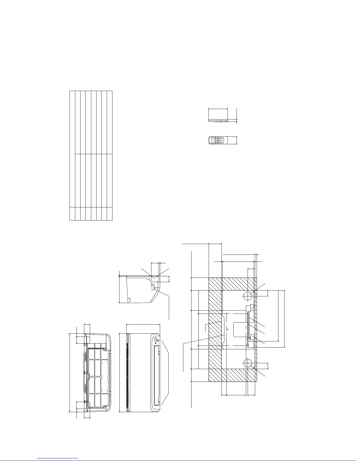
-
26
-
'15 • SRK-T-171
2. EXTERIOR DIMENSIONS
(1) Indoor units
Models SRK05CR-S, S3, S6
SRK05CRP-S, S3
SRK09CR-S, S3, S4, S5
SRK09CRP-S, S3, S5
Note(1)Themodelnamelabelisattached
ontheundersideofthepanel.
60
150
17.3
2555
45
55
45
25
615
615
262
3210
45
609
44
56
247.1
(Servicespace)
15
7.2 7.7
44
56 40152.1
100
(Servicespace)
155.4
181.9 250 181.9
100
(Servicespace)
303 155.4
Unit
100
(Servicespace)
445.9
398.2
Installationplate
Unit:mm
Wirelessremotecontrol
Spaceforinstallationandservicewhenviewingfromthefront
Holeonwallforrightrearpiping
Holeonwallforleftrearpiping
Outletforwiring
Drainhose
Liquidpiping
F
ECD
B
Symbol
(φ65)
VP16
)eralF()"4/1(53.6φ
Content
(φ65)
Outletforpiping(onbothside)
G
Outletfordownpiping
(Refertotheaboveview)
D E AB C
Gaspiping
A
)eralF()"8/3(25.9φ
G
F
Terminalblock
Page 29
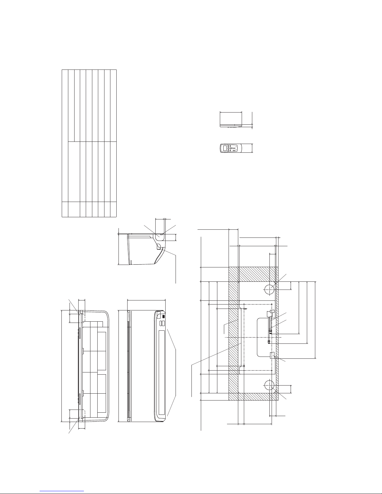
-
27
-
'15 • SRK-T-171
G
Terminal block
F
GG
Unit:mm
Wireless remote control
Outlet for down piping
(Refer to the above view)
Space for installation and service when viewing from the front
D E C
Hole on wall for right rear piping
Hole on wall for left rear piping
Gas piping
Outlet for wiring
Drain hose
Liquid piping
F
ECD
B
Symbol
A
(φ65)
VP16
φ6.35(1/4")(Flare)
Content
(φ65)
Outlet for piping(on both side)
G
Model 09 ; φ9.52(3/8")(Flare)
Model 12 ; φ12.7(1/4")(Flare)
AB
Note(1)The model name label is attached
on the underside of the indoor unit.
60
150
17.3
190 40.1
47
130.5 508 130.5
157 455 157
187.5 394 187.5
47
7.6247.56.9
(Service space)
65
(Service space)
15
50
(Service space)
100
(Service space)
55
409
449
530
55
Installation plate
Unit
6025 60 25
768.1
45
45
769
262
45
609
210 3
Models SRK09CRR-S, S3, S4, S5, S6
SRK12CR-S, S3, S4, S5, S6
Page 30
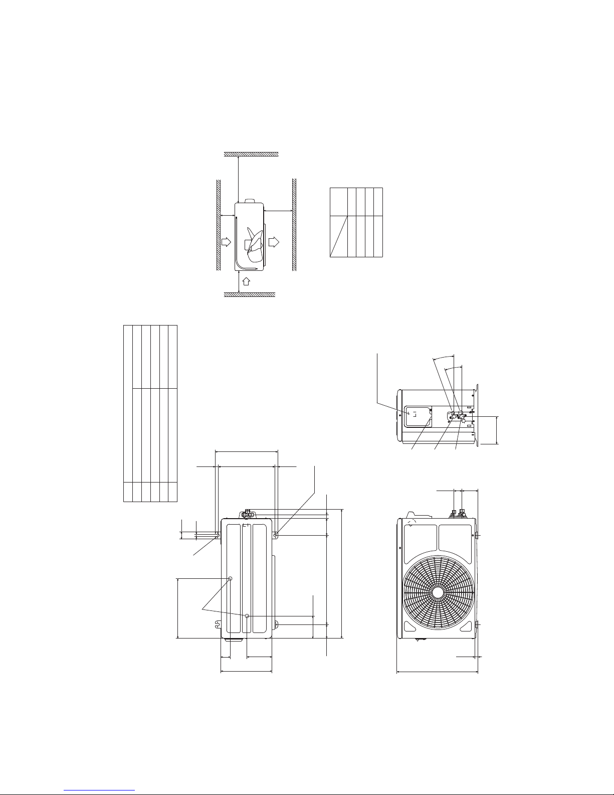
-
28
-
'15 • SRK-T-171
(2) Outdoor units
Models SRC05CR-S, S3, S6
SRC05CRP-S, S3
SRC09CR-S, S3, S4, S5
SRC09CRP-S, S3, S5
SRC09CRR-S, S3, S4, S5, S6
)eralF()"8/3(25.9φ
Content
C Pipe/cable draw-out hole
D
E Anchor bolt hole
Drain discharge hole
Symbol
B
A Service valve connection(gas side)
M10×4places
φ20×2places
Service valve connection(liquid side)
)eralF()"4/1
(
53.6φ
Minimum installation space
Notes
.sedisruofllanosllawybdednuorrusebtontsumtI)1(
(2)The unit must be fixed with anchor bolts. An anchor bolt must not
protrude more than 15mm.
(3)Where the unit is subject to strong winds, lay it in such
a direction that the blower outlet faces perpendicular ly
to the dominant wind direction.
(4)Leave 1m or more space above the unit.
(5)A wall in front of the blower outlet must not exceed the unit height.
(6)The model name label is attached on the right side of the unit.
L2
L3
L4
L1 600
100
100
Examples of
Dimensions
Unit:mm
mm
installation
Outlet
Intake
L3
L1
L2
Intake
Service
space
( )
L4
Open
322
50
40
12
135
275
120.5
74.5 480 91 19.7
694.2
16.8304.414.8
336
2-16x12
Terminal block
147.2
2
0
°
20
°
86.3 43.2
16.5
437
E
D
BCA
Page 31

-
29
-
'15 • SRK-T-171
Models SRC12CR-S, S3, S4, S5, S6
)eralF()"4/1(53.6φ
Content
C Pipe/cable draw-out hole
D
E Anchor bolt hole
Drain discharge hole
Symbol
B
A Service valve connection(gas side)
M10×4places
φ20×2places
Service valve connection(liquid side)
)eralF()"2/1(7.21φ
L2
Intake
Outlet
Intake
L3
L1
Minimum installation space
Service
space
( )
Notes
.sedisruofllanosllawybdednuorrusebtontsumtI)1(
(2) The unit must be fixed with anchor bolts. An anchor bolt must not
protrude more than 15mm.
(3) Where the unit is subject to strong winds, lay it in such
a direction that the blower outlet faces perpendicularly
to the dominant wind direction.
(4) Leave 1m or more space above the unit.
(5) A wall in front of the blower outlet must not exceed the unit height.
(6) The model name label is attached on the right side of the unit.
L4
L2
L3
L4
L1
100
100
600
Open
Examples of
Dimensions
installation
15.8
543.8
390.6
390.6
63.469.4
290
111.6 510 158.4
780 61.9
18.9
14.8
351.6
2-16x12
312.5 24.3
50.6
12
97.7 42.5
Terminal block
40
°
4
0
°
138.4 33.5
19.9
D
E
A
C
B
Unit:mm
mm
Page 32

-
30
-
'15 • SRK-T-171
(3) Wireless remote control
Unit: mm
60
17.3
150
All models
Unit: mm
17.3
150
Page 33

-
31
-
'15 • SRK-T-171
3. ELECTRICAL WIRING
(1) Indoor units
All models
Printedcircuitboard
Wireless
R-Amp
Display
CNE
WH
RD
BK
M
CNW
IC15
ZNR
1
5
3
CNU
CF
I
52C
F
250V3.15A
CONTROLBOX
BackupSw
CNG
CNM
N
U
1〜
MFM
FM
I
t°
t°
Th1
Th2
T1
2/N
L
1
BL
WH
BK
Powersource
220~240V50Hz
T2
1
L
52C-3
INDOORUNIT
OUTDOORUNIT
BK
Colorsymbol
BL
Black
Blue
RD
WH
Red
White
Symbol
MeaningofMarks
Partsname Symbol Partsname
CapacitorforCF
I
FM
I
FM
FM
I
Fuse
Fanmotor
Flapmotor
F
Th2
T1,T2
Roomtemp.thermistor
Heatexchangerthermistor
Terminalblock
Th1
ZNR Varistor
2
Page 34

-
32
-
'15 • SRK-T-171
(2) Outdoor units
Models SRC05CR-S, S3, S6
SRC05CRP-S, S3
WHITE
L
1
2/N
RED
1
2
3
WHITE
WHITE
WHITE
S
C
R
BLACK
BLACK
*:BLACKORBROWN
BLACK
CM
51C
Cc
FMo
CFo
BLACK
CAPACITOR
ORANGE
ORANGE
ORANGE
21
RED
WHITE
T1
Powersource
220~240V50Hz
T2
INDOORUNIT
DESCRIPTION
ITEM
CM
FMo
Cc
CFo
T1
T2
51C
COMPRESSORMOTOR
FANMOTOR
RUNNINGCAPACITORFORCOMPRESSOR
TERMINALBLOCKINDOORUNIT
TERMINALBLOCKOUTDOORUNIT
MOTORPROTECTOR
RUNNINGCAPACITORFORFANMOTOR
OUTDOORUNIT
Models SRC09CR-S, S3, S4, S5
SRC09CRP-S, S3, S5
SRC09CRR-S, S3, S4, S5, S6
WHITE
L
1
2/N
RED
WHITE
WHITE
WHITE
S
C
R
BLACK
BLACK
BLACK
CM
Cc
FMo
CFo
BLACK
CAPACITOR
ORANGE
ORANGE
ORANGE
2
1
RED
WHITE
T1
Powersource
220~240V50Hz
T2
INDOORUNIT
DESCRIPTION
ITEM
CM
FMo
Cc
CFo
T1
T2
COMPRESSORMOTOR
FANMOTOR
RUNNINGCAPACITORFORCOMPRESSOR
TERMINALBLOCKINDOORUNIT
TERMINALBLOCKOUTDOORUNIT
RUNNINGCAPACITORFORFANMOTOR
OUTDOORUNIT
Page 35

-
33
-
'15 • SRK-T-171
Models SRC12CR-S, S3, S4, S5, S6
WHITE
L
1
2/N
WHITE
RED
WHITE
WHITE
S
C
R
BLACK
BLACK
BLACK
CM
Cc
FMo
CFo
BLACK
CAPACITOR
ORANGE
ORANGE
ORANGE
1
2
RED
WHITE
T1
Powersource
220~240V50Hz
T2
INDOORUNIT
DESCRIPTION
ITEM
CM
FMo
Cc
CFo
T1
T1
COMPRESSORMOTOR
FANMOTOR
RUNNINGCAPACITORFORCOMPRESSOR
TERMINALBLOCKINDOORUNIT
TERMINALBLOCKOUTDOORUNIT
RUNNINGCAPACITORFORFANMOTOR
OUTDOORUNIT
Page 36

-
34
-
'15 • SRK-T-171
Condition
MODE
ISO5151 T1 ,JIS C9612
SRK05CRP-S,S3
Rated capacity value
10
20
30
40
50
60
70
10
20
30
40
50
60
70
125 250 500 1000 2000 4000 8000
N50
N 30
N 40
N60
N70
N 20
× Cooling
63
4. NOISE LEVEL
Models SRK05CRP-S, S3
(Indoor Unit)
Model SRK05CRP-S, S3
Noise Level
Cooling 42 dB(A)
Condition
ISO5151T1,JIS C 9612
●
Mike position as below
0.8m
1m
Unit
Mike position
(Center & Low points)
×
......
Cooling
N30
10
20
30
40
50
60
70
Sound Pressure Level (dB)
(Standard 2×10
-5
P a )
Mid Octave Band Frequency (Hz)
63 125 250 500 1000 2000 4000 8000
10
20
30
40
50
60
70
N70
N60
N50
N40
N20
●
Mike position: at highest noise level in position as mentined below
Distance from front side 1m
●
Mike position as below
0.8m
1m
Unit
Mike position
(Center & Low points)
10
20
30
40
50
60
70
Sound Pressure Level (dB)
(Standard 2×10
-5
P a )
Mid Octave Band Frequency (Hz)
63 125 250 500 1000 2000 4000 8000
10
20
30
40
50
60
70
N70
N60
N50
N40
N30
N20
(Ondoor Unit)
Model SRC05CRP-S, S3
Noise Level
Cooling 50 dB(A)
×
......
Cooling
N30
Mid Octave Band Frequency (Hz)
10
20
30
40
50
60
70
N70
N60
N50
N40
N20
Condition
MODE
ISO5151 T1 ,JIS C9612
SRK05CRP-S,S3
Rated capacity value
SRC05CRP-S,S3
10
20
30
40
50
60
70
10
20
30
40
50
60
70
125 250 500 1000 2000 4000 8000
Mid Octave Band Frequency(Hz)
N50
N 30
N 40
N60
N70
N 20
10
20
30
40
50
60
70
10
20
30
40
50
60
70
125
250
500
1000 2000 4000 8000
N50
N30
N40
N60
N 70
N 20
× Cooling
63
× Cooling
63
10
20
30
40
50
60
70
Mid Octave Band Frequency (Hz)
63 125 250 500 1000 2000 4000 8000
10
20
30
40
50
60
70
N70
N60
N50
N40
N30
N20
MODE Rated capacity value
Page 37

-
35
-
'15 • SRK-T-171
Models SRK05CR-S, S3, S6
(Indoor Unit)
Model SRK05CR-S, S3, S6
Noise Level
Cooling 42 dB(A)
●
Mike position as below
0.8m
1m
Unit
Mike position
(Center & Low points)
×
......
Cooling
10
20
30
40
50
60
70
Sound Pressure Level (dB)
(Standard 2×10
-5
P a )
Mid Octave Band Frequency (Hz)
63 125 250 500 1000 2000 4000 8000
10
20
30
40
50
60
70
N70
N60
N50
N40
N30
N20
N70
N60
N50
N40
N30
N20
10
20
30
40
50
60
70
Sound Pressure Level (dB)
(Standard 2×10
-5
P a )
Mid Octave Band Frequency (Hz)
63 125 250 500 1000 2000 4000 8000
10
20
30
40
50
60
70
●
Mike position: at highest noise level in position as mentined below
Distance from front side 1m
●
Mike position as below
0.8m
1m
Unit
Mike position
(Center & Low points)
(Ondoor Unit)
Model SRC05CR-S, S3, S6
Noise Level
Cooling 48 dB(A)
×
......
Cooling
Mid Octave Band Frequency (Hz)
10
20
30
40
50
60
70
N70
N60
N50
N40
N30
N20
N70
N60
N50
N40
N30
N20
Mid Octave Band Frequency (Hz)
10
20
30
40
50
60
70
Condition
ISO5151T1,JIS C 9612
MODE Rated capacity value
10
20
30
40
50
60
70
10
20
30
40
50
60
70
125 250 500 1000 2000 4000 8000
N50
N30
N40
N60
N70
N20
63
10
20
30
40
50
60
70
10
20
30
40
50
60
70
125 250 500 1000 2000 4000 8000
N50
N30
N40
N60
N70
N20
10
20
30
40
50
60
70
10
20
30
40
50
60
70
125
250
500
1000 2000 4000 8000
N50
N30
N40
N60
N70
N20
63
63
Page 38

-
36
-
'15 • SRK-T-171
Models SRK09CRR-S, S3, S4, S5
(Indoor Unit)
Model SRK09CRR-S, S3, S4, S5
Noise Level
Cooling 43 dB(A)
×
......
Cooling
10
20
30
40
50
60
70
Sound Pressure Level (dB)
(Standard 2×10
-5
P a )
Mid Octave Band Frequency (Hz)
63 125 250 500 1000 2000 4000 8000
10
20
30
40
50
60
70
N70
N60
N50
N40
N30
N20
N70
N60
N50
N40
N30
N20
10
20
30
40
50
60
70
Sound Pressure Level (dB)
(Standard 2×10
-5
P a )
Mid Octave Band Frequency (Hz)
63 125 250 500 1000 2000 4000 8000
10
20
30
40
50
60
70
(Ondoor Unit)
Model SRK09CRR-S, S3, S4, S5
Noise Level
Cooling 50 dB(A)
×
......
Cooling
Mid Octave Band Frequency (Hz)
10
20
30
40
50
60
70
N70
N60
N50
N40
N30
N20
N70
N60
N50
N40
N30
N20
Mid Octave Band Frequency (Hz)
10
20
30
40
50
60
70
Condition
ISO5151T1,JIS C 9612
MODE Rated capacity value
Condition
MODE
× Cooling
ISO5151 T1 ,JIS C 9612
SRK09CRR-S,S3,S4,S5
Rated capacity value
10
20
30
40
50
60
70
10
20
30
40
50
60
70
125
250
500
1000 2000 4000 8000
N50
N30
N40
N60
N70
N20
63
Condition
MODE
× Cooling
ISO5151 T1 ,JIS C 9612
SRK09CRR-S,S3,S4,S5
Rated capacity value
SRC09CRR-S,S3,S4,S5,S6
10
20
30
40
50
60
70
10
20
30
40
50
60
70
125
250
500
1000 2000 4000 8000
Mid Octave Band Frequency(Hz)
N50
N30
N40
N60
N70
N20
10
20
30
40
50
60
70
10
20
30
40
50
60
70
125
250
500
1000 2000 4000 8000
N50
N30
N 40
N60
N70
N 20
63
× Cooling
63
●
Mike position as below
0.8m
1m
Unit
Mike position
(Center & Low points)
●
Mike position: at highest noise level in position as mentined below
Distance from front side 1m
●
Mike position as below
0.8m
1m
Unit
Mike position
(Center & Low points)
Page 39

-
37
-
'15 • SRK-T-171
Condition
ISO5151 T1 ,JIS C9612
SRK09CRP-S,S3,S5
10
20
30
40
50
60
70
10
20
30
40
50
60
70
125
250
500
1000 2000 4000 8000
N50
N30
N40
N60
N70
N20
× Cooling
63
Models SRK09CRP-S, S3, S5
(Indoor Unit)
Model SRK09CRP-S, S3, S5
Noise Level
Cooling 43 dB(A)
×
......
Cooling
10
20
30
40
50
60
70
Sound Pressure Level (dB)
(Standard 2×10
-5
P a )
Mid Octave Band Frequency (Hz)
63 125 250 500 1000 2000 4000 8000
10
20
30
40
50
60
70
N70
N60
N50
N40
N30
N20
N70
N60
N50
N40
N30
N20
10
20
30
40
50
60
70
Sound Pressure Level (dB)
(Standard 2×10
-5
P a )
Mid Octave Band Frequency (Hz)
63 125 250 500 1000 2000 4000 8000
10
20
30
40
50
60
70
(Ondoor Unit)
Model SRK09CRP-S, S3, S5
Noise Level
Cooling 51 dB(A)
×
......
Cooling
Mid Octave Band Frequency (Hz)
10
20
30
40
50
60
70
N70
N60
N50
N40
N30
N20
N70
N60
N50
N40
N30
N20
Mid Octave Band Frequency (Hz)
10
20
30
40
50
60
70
Condition
ISO5151T1,JIS C 9612
●
Mike position as below
0.8m
1m
Unit
Mike position
(Center & Low points)
●
Mike position: at highest noise level in position as mentined below
Distance from front side 1m
●
Mike position as below
0.8m
1m
Unit
Mike position
(Center & Low points)
Condition
SRK09CRP-S,S3,S5
ISO5151 T1 ,JIS C9612
SRK09CRP-S,S3,S5
10
20
30
40
50
60
70
10
20
30
40
50
60
70
125
250
500
1000 2000 4000 8000
Mid Octave Band Frequency(Hz)
N50
N30
N40
N60
N70
N20
10
20
30
40
50
60
70
10
20
30
40
50
60
70
125
250
500
1000 2000 4000 8000
N50
N30
N40
N60
N70
N20
× Cooling
63
× Cooling
63
Page 40

-
38
-
'15 • SRK-T-171
Condition
ISO5151 T1 ,JIS C9612
SRK09CR-S,S3,S4,S5
10
20
30
40
50
60
70
10
20
30
40
50
60
70
125
250
500
1000 2000 4000 8000
N50
N 30
N40
N 60
N 70
N 20
× Cooling
63
Models SRK09CR-S, S3, S4, S5
(Indoor Unit)
Model SRK09CR-S, S3, S4, S5
Noise Level
Cooling 43 dB(A)
●
Mike position as below
0.8m
1m
Unit
Mike position
(Center & Low points)
×
......
Cooling
10
20
30
40
50
60
70
Sound Pressure Level (dB)
(Standard 2×10
-5
P a )
Mid Octave Band Frequency (Hz)
63 125 250 500 1000 2000 4000 8000
10
20
30
40
50
60
70
N70
N60
N50
N40
N30
N20
N70
N60
N50
N40
N30
N20
10
20
30
40
50
60
70
Sound Pressure Level (dB)
(Standard 2×10
-5
P a )
Mid Octave Band Frequency (Hz)
63 125 250 500 1000 2000 4000 8000
10
20
30
40
50
60
70
●
Mike position: at highest noise level in position as mentined below
Distance from front side 1m
●
Mike position as below
0.8m
1m
Unit
Mike position
(Center & Low points)
(Ondoor Unit)
Model SRK09CR-S, S3, S4, S5
Noise Level
Cooling 50 dB(A)
×
......
Cooling
Mid Octave Band Frequency (Hz)
10
20
30
40
50
60
70
N70
N60
N50
N40
N30
N20
N70
N60
N50
N40
N30
N20
Mid Octave Band Frequency (Hz)
10
20
30
40
50
60
70
Condition
ISO5151T1,JIS C 9612
Condition
× Cooling
SRK09CR-S,S3,S4,S5
ISO5151 T1 ,JIS C9612
SRK09CR-S,S3,S4,S5
10
20
30
40
50
60
70
10
20
30
40
50
60
70
125
250
500
1000 2000 4000 8000
Mid Octave Band Frequency(Hz)
N50
N 30
N40
N 60
N 70
N 20
10
20
30
40
50
60
70
10
20
30
40
50
60
70
63
125
250
500
1000 2000 4000 8000
N50
N30
N40
N60
N 70
N20
× Cooling
63
Page 41

-
39
-
'15 • SRK-T-171
Condition
MODE
× Cooling
ISO5151 T1 ,JIS C 9612
SRK12CR-S,S3,S4,S5,S6
Rated capacity value
10
20
30
40
50
60
70
10
20
30
40
50
60
70
125 250 500 1000 2000 4000 8 000
N50
N30
N 40
N60
N70
N20
63
Models SRK12CR-S, S3, S4, S5, S6
(Indoor Unit)
Model SRK12CR-S, S3, S4, S5, S6
Noise Level
Cooling 43 dB(A)
●
Mike position as below
0.8m
1m
Unit
Mike position
(Center & Low points)
×
......
Cooling
10
20
30
40
50
60
70
Sound Pressure Level (dB)
(Standard 2×10
-5
P a )
Mid Octave Band Frequency (Hz)
63 125 250 500 1000 2000 4000 8000
10
20
30
40
50
60
70
N70
N60
N50
N40
N30
N20
N70
N60
N50
N40
N30
N20
10
20
30
40
50
60
70
Sound Pressure Level (dB)
(Standard 2×10
-5
P a )
Mid Octave Band Frequency (Hz)
63 125 250 500 1000 2000 4000 8000
10
20
30
40
50
60
70
●
Mike position: at highest noise level in position as mentined below
Distance from front side 1m
●
Mike position as below
0.8m
1m
Unit
Mike position
(Center & Low points)
(Ondoor Unit)
Model SRK12CR-S, S3, S4, S5, S6
Noise Level
Cooling 50 dB(A)
×
......
Cooling
Mid Octave Band Frequency (Hz)
10
20
30
40
50
60
70
N70
N60
N50
N40
N30
N20
N70
N60
N50
N40
N30
N20
Mid Octave Band Frequency (Hz)
10
20
30
40
50
60
70
Condition
ISO5151T1,JIS C 9612
MODE Rated capacity value
Condition
MODE
× Cooling
× Cooling
ISO5151 T1 ,JIS C 9612
SRK12CR-S,S3,S4,S5,S6
Rated capacity value
SRC12CR-S,S3,S4,S5,S6
10
20
30
40
50
60
70
10
20
30
40
50
60
70
125 250 500 1000 2000 4000 8 000
Mid Octave Band Frequency(Hz)
N50
N30
N 40
N60
N70
N20
10
20
30
40
50
60
70
10
20
30
40
50
60
70
125 250 500 1000 2000 4000 8000
N50
N30
N40
N60
N70
N20
63
63
Page 42

-
40
-
'15 • SRK-T-171
5. PIPING SYSTEM
Outdoor unitIndoor unit
Room temp.
sensor
Heat
exchanger
Flare connecting
Heat
exchanger
sensor
Piping
(Liquid)
ø6.35
Check joint
Service valve (Liquid)
Flare connecting
Heat
exchanger
Compressor
Accumulator
Service valve
(Gas)
Capillary tube
ø9.52
Piping
(Gas)
Outdoor unitIndoor unit
Room temp.
sensor
Heat
exchanger
Flare connecting
Heat
exchanger
sensor
Piping
(Liquid)
ø6.35
Check joint
Service valve (Liquid)
Flare connecting
Heat
exchanger
Compressor
Capillary tube
Accumulator
Service valve
(Gas)
Capillary tube
Piping
(Gas)
ø12.7
Models SRK05CR-S, S3, S6
SRK05CRP-S, S3
SRK09CR-S, S3, S4, S5
SRK09CRP-S, S3, S5
SRC09CRR-S, S3, S4, S5, S6
Models SRK12CR-S, S3, S4, S5, S6
Page 43

-
41
-
'15 • SRK-T-171
6. RANGE OF USAGE & LIMITATIONS
Net capacity = Capacity shown on specification Correction factors as follows.
(1) Coefficient of cooling capacity in relation to temperatures
All model
Models
Item
Indoor return air temperature
(
Upper, lower limits
)
Outdoor air temperature
(
Upper, lower limits
)
Refer to the selection chart
Refrigerant line (one way) length
Max. 15m
Max. 5m (Outdoor unit is higher
)
Max. 5m (Outdoor unit is lower
)
Min. 3 minutes
Max. 10 times/h
Min. 85% of rating
Vertical height difference between
outdoor unit and indoor unit
Power source voltage
Voltage at starting
Frequency of ON−OFF cycle
ON and OFF interval
Rating 10%
14 16 18 20 22
15
20
25
30
35
40
0.6
0.7
0.8
0.9
1.0
1.1
1.2
1.3
43
24
ISO-T1 Standard ConditionIndoor air W.B. temperature °C W.B.
Cooling
Applicable range
Coefficient of cooling
capacity in relation
to temperature
Cooling operation
Outdoor air D.B.
temperature
°C D.B.
Page 44

-
42
-
'15 • SRK-T-171
(2) Correction of cooling capacity in relation to one way length of refrigerant piping
How to obtain the cooling capacity
=
Piping length [m]
Cooling
7
1.0
10
0.99 0.975
15
1500
SRK05CR-S
SRK05CR-S
1463
Page 45

-
43
-
'15 • SRK-T-171
Models SRK05CR-S, S3, S6
Cooling Mode
Capacity 1.465 kW
Wind Hi
Air flow 8.5 (m
3
/min)
Cooling Mode
Capacity 1.465 kW
Wind Hi
Air flow 8.5 (m
3
/min)
14
℃WB 16 ℃WB 18 ℃W B 19 ℃W B 20 ℃W B 22 ℃W B 24 ℃W B
21
℃DB 23 ℃DB 26 ℃DB 27 ℃DB 28 ℃DB 31 ℃DB 33 ℃DB
TC SHC TC SHC TC SHC TC SHC TC SHC TC SHC TC SHC
10 1.65 1.51 1.73 1.48 1.79 1.57 1.82 1.55 1.85 1.53 1.91 1.61 1.96 1.57
12 1.62 1.49 1.70 1.46 1.77 1.55 1.80 1.54 1.83 1.52 1.89 1.60 1.94 1.56
14 1.59 1.48 1.67 1.45 1.74 1.54 1.77 1.53 1.81 1.52 1.87 1.59 1.92 1.55
16 1.56 1.46 1.64 1.44 1.71 1.54 1.75 1.52 1.78 1.50 1.84 1.58 1.90 1.55
18 1.53 1.45 1.61 1.43 1.68 1.52 1.72 1.51 1.76 1.50 1.82 1.57 1.88 1.53
20 1.49 1.43 1.57 1.42 1.66 1.51 1.69 1.50 1.73 1.49 1.80 1.57 1.86 1.52
22 1.46 1.42 1.54 1.4
0 1.63 1.50 1.67 1.49 1.70 1.48 1.77 1.54 1.83 1.51
24 1.42 1.40 1.50 1.39 1.60 1.49 1.64 1.48 1.67 1.47 1.75 1.54 1.81 1.51
26 1.39 1.39 1.47 1.37 1.56 1.47 1.61 1.47 1.64 1.45 1.72 1.53 1.78 1.50
28 1.35 1.35 1.43 1.36 1.53 1.46 1.58 1.46 1.61 1.44 1.69 1.52 1.76 1.50
30 1.31 1.31 1.39 1.34 1.50 1.45 1.55 1.44 1.58 1.43 1.66 1.52 1.73 1.49
32 1.28 1.28 1.36 1.32 1.46 1.44 1.51 1.43 1.55 1.42 1.64 1.51 1.70 1.48
34 1.24 1.24 1.32 1.31 1.43 1.42 1.48 1.42 1.52 1.41 1.61 1.50 1.67 1.48
35 1.22 1.22 1
.30 1.30 1.41 1.41 1.47 1.41 1.50 1.40 1.59 1.50 1.66 1.47
36 1.20 1.20 1.28 1.28 1.39 1.39 1.45 1.41 1.48 1.40 1.57 1.49 1.64 1.47
38 1.16 1.16 1.23 1.23 1.36 1.36 1.41 1.40 1.45 1.39 1.54 1.48 1.61 1.46
39 1.13 1.13 1.21 1.21 1.34 1.34 1.40 1.38 1.43 1.37 1.53 1.48 1.60 1.45
Outdoor DB
Hi
14
℃WB 16 ℃W B 18 ℃W B 19 ℃W B 20 ℃W B 22 ℃W B 24 ℃W B
21
℃DB 23 ℃DB 26 ℃DB 27 ℃DB 28 ℃DB 31 ℃DB 33 ℃DB
TC SHC TC SHC TC SHC TC SHC TC SHC TC SHC TC SHC
10 1.65 1.50 1.73 1.48 1.79 1.56 1.82 1.54 1.85 1.53 1.91 1.59 1.96 1.56
12 1.62 1.49 1.70 1.47 1.77 1.55 1.80 1.54 1.83 1.52 1.89 1.58 1.94 1.55
14 1.59 1.48 1.67 1.45 1.74 1.54 1.77 1.52 1.81 1.51 1.87 1.58 1.92 1.55
16 1.56 1.46 1.64 1.44 1.71 1.53 1.75 1.52 1.78 1.50 1.84 1.57 1.90 1.54
18 1.53 1.45 1.61 1.43 1.68 1.52 1.72 1.51 1.76 1.49 1.82 1.57 1.88 1.54
20 1.49 1.43 1.57 1.42 1.66 1.51 1.69 1.49 1.73 1.48 1.80 1.56 1.86 1.53
22 1.46 1.42 1.54 1.4
0 1.63 1.50 1.67 1.49 1.70 1.47 1.77 1.55 1.83 1.52
24 1.42 1.40 1.50 1.38 1.60 1.48 1.64 1.47 1.67 1.46 1.75 1.54 1.81 1.51
26 1.39 1.39 1.47 1.37 1.56 1.47 1.61 1.46 1.64 1.45 1.72 1.54 1.78 1.51
28 1.35 1.35 1.43 1.35 1.53 1.45 1.58 1.44 1.61 1.43 1.69 1.53 1.76 1.50
30 1.31 1.31 1.39 1.34 1.50 1.44 1.55 1.43 1.58 1.42 1.66 1.52 1.73 1.49
32 1.28 1.28 1.36 1.32 1.46 1.43 1.51 1.42 1.55 1.41 1.64 1.51 1.70 1.48
34 1.24 1.24 1.32 1.31 1.43 1.41 1.48 1.41 1.52 1.40 1.61 1.50 1.67 1.47
35 1.22 1.22 1
.30 1.30 1.41 1.41 1.47 1.40 1.50 1.39 1.59 1.49 1.66 1.47
36 1.20 1.20 1.28 1.28 1.39 1.39 1.45 1.40 1.48 1.39 1.57 1.49 1.64 1.46
38 1.16 1.16 1.23 1.23 1.36 1.36 1.41 1.39 1.45 1.38 1.54 1.48 1.61 1.46
39 1.13 1.13 1.21 1.21 1.34 1.34 1.40 1.38 1.43 1.37 1.53 1.47 1.60 1.45
Outdoor DB
Indoor temperature
Hi
Indoor temperature
(kW)
(kW)
Models SRK05CRP-S, S3
7. CAPACITY TABLES
TC: Total cooling capacity (kW)
SHC: Sensible heat capacity (kW)
Page 46

-
44
-
'15 • SRK-T-171
Cooling Mode
Capacity 2.500 kW
Wind Hi
Air flow 9 (m
3
/min)
Cooling Mode
Capacity 2.500 kW
Wind Hi
Air flow 9 (m
3
/min)
14
℃WB 16 ℃WB 18 ℃WB 19 ℃W B 20 ℃WB 22 ℃WB 24 ℃W B
21
℃DB 23 ℃DB 26 ℃DB 27 ℃DB 28 ℃DB 31 ℃DB 33 ℃DB
TC SHC TC SHC TC SHC TC SHC TC SHC TC SHC TC SHC
10 2.82 2.18 2.95 2.15 3.06 2.22 3.11 2.19 3.16 2.16 3.26 2.22 3.34 2.16
12 2.77 2.16 2.90 2.12 3.01 2.20 3.07 2.17 3.12 2.14 3.22 2.21 3.31 2.14
14 2.71 2.13 2.85 2.10 2.97 2.18 3.03 2.16 3.08 2.13 3.18 2.19 3.28 2.13
16 2.66 2.10 2.80 2.07 2.92 2.16 2.98 2.14 3.04 2.11 3.15 2.18 3.24 2.12
18 2.60 2.07 2.74 2.05 2.88 2.14 2.94 2.12 2.99 2.09 3.11 2.17 3.20 2.11
20 2.55 2.04 2.68 2.01 2.83 2.12 2.89 2.10 2.95 2.08 3.07 2.15 3.17 2.09
22 2.49 2.01 2.63 1.9
9 2.78 2.10 2.84 2.08 2.90 2.06 3.02 2.13 3.13 2.06
24 2.43 1.99 2.57 1.96 2.72 2.06 2.80 2.05 2.85 2.03 2.98 2.12 3.08 2.05
26 2.37 1.96 2.51 1.94 2.67 2.05 2.74 2.03 2.80 2.01 2.93 2.09 3.04 2.04
28 2.31 1.92 2.44 1.91 2.61 2.03 2.69 2.01 2.75 2.00 2.89 2.08 3.00 2.03
30 2.24 1.89 2.38 1.88 2.56 2.00 2.64 1.99 2.70 1.97 2.84 2.06 2.95 2.02
32 2.18 1.86 2.31 1.85 2.50 1.97 2.58 1.97 2.64 1.95 2.79 2.05 2.90 2.00
34 2.11 1.82 2.25 1.82 2.44 1.95 2.53 1.95 2.59 1.93 2.74 2.03 2.85 1.99
35 2.08 1.81 2
.21 1.79 2.41 1.94 2.50 1.93 2.56 1.92 2.71 2.02 2.83 1.98
36 2.04 1.79 2.18 1.78 2.38 1.92 2.47 1.92 2.53 1.91 2.69 2.01 2.80 1.97
38 1.97 1.76 2.11 1.75 2.32 1.90 2.41 1.90 2.47 1.88 2.63 1.99 2.75 1.95
39 1.94 1.75 2.07 1.74 2.28 1.89 2.38 1.89 2.44 1.87 2.61 1.98 2.72 1.94
Hi
Indoor temperature
Outdoor DB
14
℃WB 16 ℃WB 18 ℃WB 19 ℃W B 20 ℃WB 22 ℃WB 24 ℃W B
21
℃DB 23 ℃DB 26 ℃DB 27 ℃DB 28 ℃DB 31 ℃DB 33 ℃DB
TC SHC TC SHC TC SHC TC SHC TC SHC TC SHC TC SHC
10 2.82 2.18 2.95 2.14 3.06 2.21 3.11 2.19 3.16 2.16 3.26 2.22 3.34 2.15
12 2.77 2.15 2.90 2.12 3.01 2.20 3.07 2.17 3.12 2.14 3.22 2.21 3.31 2.14
14 2.71 2.13 2.85 2.10 2.97 2.18 3.03 2.15 3.08 2.12 3.18 2.19 3.28 2.13
16 2.66 2.09 2.80 2.07 2.92 2.16 2.98 2.13 3.04 2.10 3.15 2.18 3.24 2.10
18 2.60 2.07 2.74 2.04 2.88 2.13 2.94 2.11 2.99 2.09 3.11 2.16 3.20 2.09
20 2.55 2.04 2.68 2.02 2.83 2.10 2.89 2.09 2.95 2.06 3.07 2.13 3.17 2.08
22 2.49 2.01 2.63 1.9
9 2.78 2.09 2.84 2.07 2.90 2.05 3.02 2.12 3.13 2.07
24 2.43 1.98 2.57 1.96 2.72 2.07 2.80 2.05 2.85 2.03 2.98 2.11 3.08 2.06
26 2.37 1.95 2.51 1.93 2.67 2.05 2.74 2.03 2.80 2.01 2.93 2.10 3.04 2.05
28 2.31 1.92 2.44 1.90 2.61 2.02 2.69 2.01 2.75 1.99 2.89 2.08 3.00 2.03
30 2.24 1.89 2.38 1.87 2.56 1.99 2.64 1.99 2.70 1.97 2.84 2.06 2.95 2.01
32 2.18 1.85 2.31 1.84 2.50 1.97 2.58 1.97 2.64 1.95 2.79 2.04 2.90 2.00
34 2.11 1.83 2.25 1.81 2.44 1.95 2.53 1.94 2.59 1.93 2.74 2.03 2.85 1.98
35 2.08 1.81 2
.21 1.80 2.41 1.94 2.50 1.93 2.56 1.91 2.71 2.02 2.83 1.97
36 2.04 1.79 2.18 1.78 2.38 1.92 2.47 1.92 2.53 1.91 2.69 2.01 2.80 1.97
38 1.97 1.76 2.11 1.75 2.32 1.89 2.41 1.90 2.47 1.88 2.63 1.99 2.75 1.95
39 1.94 1.74 2.07 1.74 2.28 1.87 2.38 1.87 2.44 1.86 2.61 1.98 2.72 1.94
Hi
Outdoor DB
Models SRK09CRP-S, S3, S5
(kW)
(kW)
Indoor temperature
Models SRK09CR-S, S3, S4, S5
TC: Total cooling capacity (kW)
SHC: Sensible heat capacity (kW)
Page 47

-
45
-
'15 • SRK-T-171
Cooling Mode
Capacity 2.638 kW
Wind Hi
Air flow 10.2 (m
3
/min)
14
℃WB 16 ℃WB 18 ℃WB 19 ℃W B 20 ℃WB 22 ℃WB 24 ℃W B
21
℃DB 23 ℃DB 26 ℃DB 27 ℃DB 28 ℃DB 31 ℃DB 33 ℃DB
TC SHC TC SHC TC SHC TC SHC TC SHC TC SHC TC SHC
10 2.97 2.44 3.11 2.40 3.23 2.50 3.28 2.47 3.34 2.44 3.43 2.53 3.53 2.46
12 2.92 2.41 3.06 2.37 3.18 2.48 3.24 2.46 3.30 2.43 3.40 2.52 3.49 2.45
14 2.86 2.39 3.00 2.35 3.13 2.46 3.19 2.44 3.25 2.41 3.36 2.50 3.46 2.44
16 2.81 2.36 2.95 2.33 3.08 2.44 3.15 2.42 3.21 2.39 3.32 2.49 3.42 2.42
18 2.75 2.33 2.89 2.30 3.03 2.42 3.10 2.40 3.16 2.37 3.28 2.47 3.38 2.41
20 2.69 2.30 2.83 2.27 2.98 2.40 3.05 2.38 3.11 2.35 3.23 2.46 3.34 2.40
22 2.63 2.27 2.77 2.2
5 2.93 2.38 3.00 2.36 3.06 2.34 3.19 2.45 3.30 2.39
24 2.56 2.25 2.71 2.22 2.87 2.35 2.95 2.34 3.01 2.31 3.14 2.43 3.26 2.37
26 2.50 2.21 2.65 2.19 2.82 2.33 2.90 2.32 2.96 2.30 3.10 2.41 3.21 2.36
28 2.43 2.18 2.58 2.16 2.76 2.31 2.84 2.29 2.90 2.27 3.05 2.39 3.16 2.34
30 2.37 2.15 2.51 2.13 2.70 2.29 2.79 2.28 2.85 2.25 3.00 2.38 3.11 2.32
32 2.30 2.12 2.44 2.10 2.64 2.26 2.73 2.25 2.79 2.23 2.94 2.36 3.06 2.29
34 2.23 2.09 2.37 2.07 2.57 2.23 2.67 2.23 2.73 2.21 2.89 2.32 3.01 2.28
35 2.19 2.07 2
.33 2.05 2.54 2.22 2.64 2.21 2.70 2.20 2.86 2.31 2.99 2.27
36 2.15 2.05 2.30 2.04 2.51 2.21 2.61 2.20 2.67 2.19 2.84 2.31 2.96 2.26
38 2.08 2.01 2.22 2.00 2.44 2.17 2.55 2.18 2.61 2.15 2.78 2.29 2.90 2.25
39 2.04 2.00 2.18 1.98 2.41 2.16 2.51 2.16 2.58 2.14 2.75 2.28 2.87 2.24
Outdoor DB
Hi
Indoor temperature
(kW)
Models SRK09CRR-S, S3, S4, S5, S6
Cooling Mode
Capacity 3.450 kW
Wind Hi
Air flow 10 (m
3
/min)
14
℃WB 16 ℃WB 18 ℃WB 19 ℃W B 20 ℃WB 22 ℃WB 24 ℃WB
21
℃DB 23 ℃DB 26 ℃DB 27 ℃DB 28 ℃DB 31 ℃DB 33 ℃DB
TC SHC TC SHC TC SHC TC SHC TC SHC TC SHC TC SHC
10 3.89 2.94 4.07 2.88 4.22 2.97 4.29 2.93 4.36 2.89 4.49 2.96 4.61 2.86
12 3.82 2.90 4.00 2.85 4.16 2.94 4.23 2.91 4.31 2.87 4.44 2.94 4.57 2.85
14 3.74 2.86 3.93 2.81 4.10 2.91 4.18 2.88 4.25 2.84 4.39 2.92 4.52 2.83
16 3.67 2.82 3.86 2.78 4.03 2.88 4.12 2.85 4.19 2.82 4.34 2.90 4.47 2.81
18 3.59 2.78 3.78 2.73 3.97 2.85 4.05 2.82 4.13 2.79 4.29 2.88 4.42 2.79
20 3.52 2.74 3.70 2.70 3.90 2.82 3.99 2.80 4.07 2.76 4.23 2.86 4.37 2.78
22 3.44 2.70 3.63 2.6
6 3.83 2.79 3.92 2.77 4.01 2.73 4.17 2.83 4.31 2.76
24 3.35 2.65 3.54 2.63 3.76 2.75 3.86 2.73 3.94 2.70 4.11 2.81 4.26 2.72
26 3.27 2.61 3.46 2.59 3.68 2.73 3.79 2.71 3.87 2.68 4.05 2.79 4.20 2.71
28 3.18 2.57 3.37 2.55 3.61 2.69 3.72 2.68 3.80 2.65 3.99 2.75 4.14 2.69
30 3.09 2.52 3.28 2.50 3.53 2.66 3.64 2.65 3.72 2.62 3.92 2.73 4.07 2.67
32 3.00 2.48 3.19 2.46 3.45 2.62 3.57 2.62 3.65 2.59 3.85 2.71 4.01 2.65
34 2.91 2.43 3.10 2.42 3.37 2.59 3.49 2.59 3.57 2.56 3.78 2.69 3.94 2.63
35 2.86 2.41 3
.05 2.40 3.32 2.57 3.45 2.57 3.53 2.54 3.74 2.67 3.90 2.62
36 2.82 2.38 3.00 2.37 3.28 2.56 3.41 2.55 3.49 2.53 3.71 2.66 3.87 2.60
38 2.72 2.34 2.91 2.33 3.20 2.52 3.33 2.52 3.41 2.50 3.63 2.63 3.80 2.58
39 2.67 2.32 2.86 2.31 3.15 2.50 3.29 2.50 3.37 2.48 3.60 2.62 3.76 2.56
Hi
Outdoor DB
Indoor temperature
(kW)
Model SRK12CR-S
TC: Total cooling capacity (kW)
SHC: Sensible heat capacity (kW)
Page 48

-
46
-
'15 • SRK-T-171
Safety precautions
Before installation, read the “Safety precautions” carefully and strictly follow it during the installation work in order to protect yourself.w
The precautionary items mentioned below are distinguished into two levels,w
WARNING
and
CAUTION
.
WARNING
: Wrong installation would cause serious consequences such as injuries or death.
CAUTION
: Wrong installation might cause serious consequences depending on circumstances.
Both mention the important items to protect your health and safety so strictly follow them by any means.
Be sure to confirm no anomaly on the equipment by commissioning after completed installation and explain the operating methods as w
well as the maintenance methods of this equipment to the user according to the user’s manual.
Keep the installation manual together with user’s manual at a place where any user can read at any time. Moreover if necessary, ask w
to hand them to a new user.
Before starting the installation work, proper precautions (using suitable protective clothing, groves etc.) should be taken by qualifiedw
installer.
Please pay attention not to fall down the tools, etc. when installing the unit at the high position.w
If unusual noise can be heard during operation, consult the dealer.w
The meanings of “Marks” used here are shown as follows:w
Never do it under any
circumstances.
Always do it according to the
instruction.
WARNING
Installation must be carried out by the qualified installer.w
If you install the system by yourself, it may cause serious trouble
such as water leaks, electric shocks, fire and personal injury, as a
result of a system malfunction. Do not carry out the installation and
maintenance work except by the qualified installer.
Install the system in full accordance with the installation w
manual.
Incorrect installation may cause bursts, personal injury, water leaks,
electric shocks and fire.
Be sure to use only for household and residence.w
If this appliance is installed in inferior environment such as machine
shop etc., it can cause malfunction.
Use the original accessories and the specified components forw
installation.
If parts other than those prescribed by us are used, it may cause
water leaks, electric shocks, fire and personal injury.
Install the unit in a location with good support.w
Unsuitable installation locations can cause the unit to fall resulting in
material damage and personal injury.
Ensure the unit is stable when installed, so that it can withstand w
earthquakes and strong winds.
Unsuitable installation locations can cause the unit to fall and cause
material damage and personal injury.
Ventilate the working area well in the event of refrigerantw
leakage during installation.
If the density of refrigerant exceeds the limit, please consult the
dealer and install the ventilation system, otherwise lack of oxygen
can occur, which can cause serious accident.
When installing in small rooms, take prevention measures not w
to exceed the density limit of refrigerant in the event of leakage,
referred by the formula (accordance with ISO5149).
If the density of refrigerant exceeds the limit, please consult the
dealer and install the ventilation system, otherwise lack of oxygen
can occur, which can cause serious accident.
After completing installation, check that no refrigerant leaks w
from the system.
If refrigerant leaks into the room and comes into contact with an oven
or other hot surface, poisonous gas is produced.
Use the prescribed pipes, flare nuts and tools for R410A.w
Using existing parts (for R22 or R407C) can cause the unit failure
and serious accidents due to burst of the refrigerant circuit.
Tighten the flare nut by torque wrench with specified method.w
If the flare nuts were tightened with excess torque, this may cause
burst and refrigerant leakage after a long period.
Do not open the operation valves for liquid line and gas line w
until completed refrigerant piping work, air tightness test and
evacuation.
If the compressor is operated in state of opening operation valves
before completed connection of refrigerant piping work, air can be
sucked into refrigerant circuit, which can cause burst or personal
injury due to anomalously high pressure in the refrigerant.
The electrical installation must be carried out by the qualifiedw
electrician in accordance with “the norm for electrical work” and
“national wiring regulation”, and the system must be connected
to the dedicated circuit.
Power source with insufficient capacity and incorrect function done by
improper work can cause electric shocks and fire.
Be sure to shut off the power before starting electrical work.w
Failure to shut off the power can cause electric shocks, unit failure or
incorrect function of equipment.
Be sure to use the cables conformed to safety standard and w
cable ampacity for power distribution work.
Unconformable cables can cause electric leak, anomalous heat
production or fire.
This appliance must be connected to main power source byw
means of a circuit breaker or switch (fuse 20A) with a contact
separation of at least 3mm.
When plugging this appliance, a plug conforming to the norm w
IEC60884-1 must be used.
Use the prescribed cables for electrical connection, tighten w
the cables securely in terminal block and relieve the cables
correctly to prevent overloading the terminal blocks.
Loose connections or cable mountings can cause anomalous heat
production or fire.
Arrange the wiring in the control box so that it cannot be w
pushed up further into the box. Install the service panel
correctly.
Incorrect installation may result in overheating and fire.
Be sure to fix up the service panels.w
Incorrect fixing can cause electric shocks or fire due to intrusion of
dust or water.
Be sure to switch off the power source in the event of w
installation, inspection or servicing.
If the power source is not shut off, there is a risk of electric shocks,
unit failure or personal injury due to the unexpected start of fan.
Stop the compressor before removing the pipe after shutting the w
service valve on pump down work.
If the pipe is removed when the compressor is in operation with the
service valve open, air would be mixed in the refrigeration circuit and
it could cause explosion and injuries due to abnormal high pressure
in the cooling cycle.
Only use prescribed option parts. The installation must be w
carried out by the qualified installer.
If you install the system by yourself, it can cause serious trouble such
as water leaks, electric shocks, fire.
Be sure to wear pr
otective goggles and gloves while at work.w
Earth leakage breaker must be installed.w
If the earth leakage breaker is not installed, it can cause electric
shocks.
Do not put the drainage pipe directly into drainage channelsw
where poisonous gases such as sulphide gas can occur.
Poisonous gases will flow into the room through drainage pipe and
seriously affect the user’s health and safety. This can also cause the
corrosion of the indoor unit and a resultant unit failure or refrigerant
leak.
Ensure that no air enters in the refrigerant circuit when the unit w
is installed and removed.
If air enters in the refrigerant circuit, the pressure in the refrigerant
circuit becomes too high, which can cause burst and personal injury.
Do not bundle or wind or process the power cord. Do not deformw
the power cord by treading it.
This may cause fire or heating.
Do not process or splice the power cord, or share the socketw
with other power plugs.
This may cause fire or electric shock due to defecting contact,
defecting insulation and over-current etc.
Do not vent R410A into the atmosphere : R410A is a fluorinatedw
greenhouse gas, covered by the Kyoto Protocol with Global
Warming Potential (GWP)=1975.
Do not run the unit with removed panels or protections.w
Touching rotating equipments, hot surfaces or high voltage parts can
cause personal injury due to entrapment, burn or electric shocks.
Do not perform any change of protective device itself or its w
setup condition.
The forced operation by short-circuiting protective device of pressure
switch and temperature controller or the use of non specified component
can cause fire or burst.
WALL TYPE AIR-CONDITIONER
R410A REFRIGERANT USED
While install the unit, besure to check the selection of installation place, power source
specifications, usage limitation (piping length, height differences between indoor and
outdoor units, power source voltage and etc.) and installation spaces.
8. APPLICAT10N DATA
Page 49

-
47
-
'15 • SRK-T-171
Safety precautions[
CAUTION
Carry out the electrical work for ground lead with care.•
Do not connect the ground lead to the gas line, water line, lightning conductor or telephone line’s ground lead. Incorrect grounding can cause
unit faults such as electric shocks due to short-circuiting.
Use the circuit breaker of correct capacity. Circuit breaker •
should be able to disconnect all poles under over current.
Using the incorrect one could cause the system failure and fire.
Install isolator or disconnect switch on the power source wiring •
in accordance with the local codes and regulations.
The isolator should be locked in OFF state in accordance with
EN60204-1.
Be sure to install indoor unit properly according to instruction •
manual so that drainage can run off smoothly.
Improper installation of indoor unit can cause dropping water into the
room and damaging personal property.
Install the drainage pipe to run off drainage securely according•
to the installation manual.
Incorrect installation of the drainage pipe can cause dropping water
into the room and damaging personal property.
Be sure to install the drainage pipe with descending slope of •
1/100 or more, and not to make traps and air-bleedings.
Check if the drainage runs off securely during commissioning and
ensure the space for inspection and maintenance.
After maintenance, all wiring, wiring ties and the like, should •
be returned to their original state and wiring route, and the
necessary clearance from all metal parts should be secured.
Secure a space for installation, inspection and maintenance •
specified in the manual.
Insufficient space can result in accident such as personal injury due
to falling from the installation place.
Take care when carrying the unit by hand.•
If the unit weights more than 20kg, it must be carried by two or more
persons. Do not carry by the plastic straps, always use the carry
handle when carrying the unit by hand. Use gloves to minimize the
risk of cuts by the aluminum fins.
Dispose of any packing materials correctly.•
Any remaining packing materials can cause personal injury as it contains
nails and wood. And to avoid danger of suffocation, be sure to keep the
plastic wrapper away from children and to dispose after tear it up.
For installation work, be careful not to get injured with the heat •
exchanger, piping flare portion or screws etc.
Be sure to insulate the refrigerant pipes so as not to condense •
the ambient air moisture on them.
Insufficient insulation can cause condensation, which can lead to
moisture damage on the ceiling, floor, furniture and any other valuables.
When perform the air-conditioner operation (cooling or drying•
operation) in which ventilator is installed in the room. In this
case, using the air-conditioner in parallel with the ventilator,
there is the possibility that drain water may backflow in
accordance with the room lapse into the negative pressure
status. Therefore, set up the opening port such as incorporate
the air into the room that may appropriate to ventilation (For
example; Open the door a little). In addition, just as above, so
set up the opening port if the room lapse into negative pressure
status due to register of the wind for the high rise apartment etc.
Be sure to perform air tightness test by pressurizing with •
nitrogen gas after completed refrigerant piping work.
If the density of refrigerant exceeds the limit in the event of refrigerant
leakage in the small room, lack of oxygen can occur, which can
cause serious accidents.
Do not install the unit in the locations listed below.•
Locations where carbon fiber, metal powder or any powder is floating.
•
Locations where any substances that can affect the unit such as •
sulphide gas, chloride gas, acid and alkaline can occur.
Vehicles and ships.•
Locations where cosmetic or special sprays are often used.•
Locations with direct exposure of oil mist and steam such as •
kitchen and machine plant.
Locations where any machines which generate high frequency •
harmonics are used.
Locations with salty atmospheres such as coastlines.•
Locations with heavy snow (If installed, be sure to provide base •
flame and snow hood mentioned in the manual).
Locations where the unit is exposed to chimney smoke.•
Locations at high altitude (more than 1000m high).•
Locations with ammonic atmospheres.•
Locations where heat radiation from other heat source can affect•
the unit.
Locations without good air circulation.•
Locations with any obstacles which can prevent inlet and outlet air •
of the unit.
Locations where short circuit of air can occur (in case of multiple•
units installation).
Locations where strong air blows against the air outlet of outdoor unit.
•
Locations where something located above the unit could fall.•
It can cause remarkable decrease in performance, corrosion and
damage of components, malfunction and fire.
Do not install the indoor unit in the locations listed below (Be•
sure to install the indoor unit according to the installation manual
for each model because each indoor unit has each limitation).
Locations with any obstacles which can prevent inlet and outlet air •
of the unit.
Locations where vibration can be amplified due to insufficient•
strength of structure.
Locations where the infrared receiver is exposed to the direct sunlight
•
or the strong light beam (in case of the infrared specification unit).
Locations where an equipment affected by high harmonics is placed•
(TV set or radio receiver is placed within 1m).
Locations where drainage cannot run off safely.•
It can affect performance or function and etc.
Do not install the outdoor unit in the locations listed below.•
Locations where discharged hot air or operating sound of the •
outdoor unit can bother neighborhood.
Locations where outlet air of the outdoor unit blows directly to •
plants. The outlet air can affect adversely to the plant etc.
Locations where vibration can be amplified and transmitted due to •
insufficient strength of structure.
Locations where vibration and operation sound generated by the outdoor
•
unit can affect seriously (on the wall or at the place near bed room).
Locations where an equipment affected by high harmonics is placed•
(TV set or radio receiver is placed within 1m).
Locations where drainage cannot run off safely.•
It can affect surrounding environment and cause a claim.
Do not install the unit where corrosive gas (such as sulfurous•
acid gas etc.) or combustible gas (such as thinner and
petroleum gases) can accumulate or collect, or where volatile
combustible substances are handled.
Corrosive gas can cause corrosion of heat exchanger, breakage of
plastic parts and etc. And combustible gas can cause fire.
Do not install the unit near the location where leakage of •
combustible gases can occur.
If leaked gases accumulate around the unit, it can cause fire.
Do not use the indoor unit at the place where water splashes •
may occur such as in laundries.
Since the indoor unit is not waterproof, it can cause electric shocks
and fire.
Do not install nor use the system close to the equipment that •
generates electromagnetic fields or high frequency harmonics.
Equipment such as inverters, standby generators, medical high
frequency equipments and telecommunication equipments can
affect the system, and cause malfunctions and breakdowns.The
system can also affect medical equipment and telecommunication
equipment, and obstruct its function or cause jamming.
Do not place any variables which will be damaged by getting wet•
under the indoor unit.
When the relative humidity is higher than 80% or drainage pipe is
clogged, condensation or drainage water can drop and it can cause
the damage of valuables.
Do not install the remote control at the direct sunlight.•
It can cause malfunction or deformation of the remote control.
Do not use the unit for special purposes such as storing foods,•
cooling precision instruments and preservation of animals,
plants or art.
It can cause the damage of the items.
Do not install the outdoor unit in a location where insects and •
small animals can inhabit.
Insects and small animals can enter the electric parts and cause
damage or fire. Instruct the user to keep the surroundings clean.
Do not use the base flame for outdoor unit which is corroded or •
damaged due to long periods of operation.
Using an old and damage base flame can cause the unit falling down
and cause personal injury.
Do not use any materials other than a fuse with the correct •
rating in the location where fuses are to be used.
Connecting the circuit with copper wire or other metal thread can
cause unit failure and fire.
Do not touch any buttons with wet hands.•
It can cause electric shocks.
Do not touch any refrigerant pipes with your hands when the •
system is in operation.
During operation the refrigerant pipes become extremely hot or
extremely cold depending the operating condition, and it can cause
burn injury or frost injury.
Do not touch the suction or aluminum fin on the outdoor unit.•
This may cause injury.
Do not put anything on the outdoor unit and operating unit.•
This may cause damage the objects or injury due to falling to the
object.
• Do not clean up the unit with water.
Page 50

-
48
-
'15 • SRK-T-171
① A place where good air circulation can be obtained and where rain, snow
or sunshine will not directly strike the unit.
② A place where discharged hot air or unit’s operating sound will not be a
nuisance to the neighborhood.
③ A place where servicing space can be secured.
④ A place where vibration will not be enlarged.
*Avoid installing in the following places.
t" place near the bedroom and the like, so that the operation noise will
cause no trouble.
t
A place where there is possibility of flammable gas leakage.
t"QMBDFexposed to strong wind.
t*O a salt-laden atmosphere or a place where the generation of oil mist,
vapor or fume is expected.
⑤ Blowing out port and suction port on the back side of the unit can be
installed at a distance of 10cm from walls.
*O case the barrier is 1.2m or above in height, or is overhead, the
sufficient space between the unit and wall shall be secured.
⑥ When the unit is installed, the space of the following dimension and above
shall be secured.
Note (1) *G the wall is higher than 1.2 m or a
ceiling ispresent, distances largerthan
indicated in the above table must be
provided.
Selection of installation location
① Where there is no obstructions to the air flow and where the cooled air can
be evenly distributed.
② A solid place where the unit or the wall will not vibrate.
③ A place where there will be enough space for servicing. (Where space
mentioned right can be secured)
④ Where wiring and the piping work will be easy to conduct.
⑤ The place where receiving part is not exposed to the direct rays of the sun
or the strong rays of the street lighting.
⑥ A place where it can be easily drained.
⑦
A place separated at least 1m away from the television or the radio.
(To prevent interfence to images and sounds.)
⑧ A place that home appliance and household goods, etc. aren’t below unit.
DN.*/
Air intake
DN.*/
10 cm
.*/
Air outlet
Air
intake
No obstacles
(Service space
for electrical
parts)
( )
Standard accessories
(Installation kit)
Accessories for indoor unit
Q'ty
①
Installation board
(Att ach ed to th e rear o f the in door
unit)
1
②
Wireless remote control 1
③
Remote control holde
r
1
④
Tapping screws
(for installation board 4dia. by 25mm)
5
⑤
Wood screw
(for remote contorol switch holder 3.5dia.
by 16mm)
2
⑥
Battery [R03 (AAA, Micro) 1.5V] 2
Option parts Q'ty
ⓐ
Sealing plate 1
ⓑ
Sleeve 1
ⓒ
Inclination plate 1
ⓓ
Putty 1
ⓔ
Drain hose (extention hose) 1
ⓕ
Piping cover
(for insulation of connection piping)
1
Necessary tools for the installation work
1 Plus headed driver (Phillips screwdriver)
2 Knife
3 Saw
4 Tape measure
5 Hammer
6 Spanner wrench
7 Torque wrench
(
14.0 ~ 82.0N · m
(1.4 ~ 8.2kgf · m)
)
8 Hole core drill (65mm in diameter)
9 Wrench key (Hexagon) [4m/m]
10 Vacuum pump
11
Vacuum pump adapter
(Anti-reverse
type)
(
Designed
for R410A
)
12 Gauge manifold
(
Designed
for R410A
)
13 Change hose
(
Designed
for R410A
)
14 Flaring tool set
(
Designed
for R410A
)
15
Gas leak detector
(
Designed
for R410A
)
16
Gauge for projection adjustment (Used when
is made by using conventional tool)
17 Pipe bender
Left
side
5 cm
10 cm
Right
side
10 cm
INDOOR UNIT
OUTDOOR UNIT
Page 51

-
49
-
'15 • SRK-T-171
Installation of indoor unit
Installation of installation board
• Adjustment of the installation board in the horizontal
direction is to be conducted with ve screws in a
temporary tightened state.
• Adjust so that board will be level by turning the
board with the standard hole as the center.
Standard hole
Limitations for one way piping length and vertical height difference
One way piping length ( )
15 m
Vertical height
difference (h)
Outdoor
unit is lower
5 m
Outdoor
unit is higher
5 m
Look for the inside wall structures (Inte rsediate support or pillar
and ral y install the unit after leve l surface has been checked.)
Mating mark for level surf ace
250
* Leave extra space on the right side to enable removal of the lid screw.
INSTALLATION SPACE (INDOOR UNIT) (FRONT VIEW)
Unit : mm
Space for
service
Space for
service
Space for
service
Space for
service*
Indoor unit
181.9181.9
44
44
4056
69.9
15
56
100
7.2 7.7
250
Installation board
Piping for Gas 398.2
Piping for Liquid 455.9
Drain hose 386.3 (
Ø16)
Piping hole (
Ø65)
Piping hole (Ø65)
100
100
155.4
155.4
<SRK05, 09CR / SRK05, 09CRP>
<SRK09CRR / SRK12CR>
• Adjustment of the installation board in the horizontal
direction is to be conducted with ve screws in a
temporary tightened state.
• Adjust so that board will be level by turning the
board with the standard hole as the center.
Standard hole
Look for the inside wall structures (Inte rsediate support or pillar
and ral y install the unit after leve l surface has been checked.)
Mating mark for level surf ace
394
* Leave extra space on the right side to enable removal of the lid screw.
INSTALLATION SPACE (INDOOR UNIT) (FRONT VIEW)
Unit : mm
Space for
service
Space for
service
100 Space
for service
15 Space
for service*
Indoor unit
187.5 187.5394
157 157455
130.5 130.5
55
508
55
190 40.1
47
7.66.9
47
247.5
Installation board
100
50
Piping for Gas 409
Piping for Liquid 449
Drain hose 530 (
Ø16)
Piping hole (Ø65) Piping hole (Ø65)
Page 52

-
50
-
'15 • SRK-T-171
Drilling of holes and fixture sleeve (Option parts)
Drill a hole with Ø65 whole core drill
Install the sleeve
Adjusting sleeve length
Note (1) Drill a hole with incline of 5 degree from
indoor side to outdoor side.
Wall thickness
+ 1.5 cm
Cut off the sleeve
collar that can be
seen from beneath
the unit.
Cut off the sleeve
collar in case of
drawing piping out
to rear.
Indoor side
Indoor side
Indoor side
View of sleeve when installed
Outdoor side
Outdoor side
Outdoor side
(Inserting sleeve) (*Sleeve + *Inclined + *Sealing plate)
Paste
Sleeve
Turn to
tighten
In cli ne d
flange
Seali ng
plate
Preparation of indoor unit
① Mounting of connecting wires
ⓐ Remove the lid.
ⓑRemove the wiring clamp.
ⓒConnect the connecting wire securely to the terminal block.
Use cable for interconnection wiring to avoid loosening of the wires.
CENELEC code for cables Required field cables.
75CEI542ro)elpmaxE(5.1G4RNR50H
H Harmonized cable type
05 300/500 volts
R Natural-and/or synth. rubber wire insulation
N Polychloroprene rubber conductors insulation
R Standed core
srotcudnocforebmuN5ro4
G
One conductor of the cables is the earth conductor (yellow/green)
1.5 Section of copper wire (mm2)
• Connect the connection wire securely to the terminal block. If
the wire is not affixed completely, contact will be poor, and it
is dangerous as the terminal block may heat up and catch fire.
• Take care not to confuse the terminal numbers for power
source indoor and outdoor connections.
•
Earthlead wireshall be longer than the otherleadwires forthe electrical
safety in case of the slipping out of the cord from the anchorage.
• The earth line of power cord must be properly earthed.
L
N
Connecting diagram.
Power source
Terminal on the indoor unit
L 2/N
2
N
L
1
1
Terminal on the outdoor unit
• Affix the connection wire using the wiring clamp.
ⓓFix the connecting wire by wiring clamp.
ⓔAttach the lid.
ⓕClose the air inlet panel.
② Shaping the pipe
③ Taping of the exterior
• Hold the bottom of the pipe and change its direction
before stretching it and shaping it.
• Tape only the portion that runs through the wall.
Always tape the crossover wires with the pipe.
* Leave space to allow
removal of this screw
after installation.
Pipe
Drain hose
Terminal block
Screw*
Clamp
Lid
Page 53

-
51
-
'15 • SRK-T-171
④ Cautions when piping from the left and the rear center of the unit
[ Top View ]
• R emo ve t he sc re w a nd
pull th e drain hose, w hile
twisting.
• R emove it w ith h and o r
pliers.
• I nse rt th e dr ain c ap w hich
was removed at procedure “2”
se cure ly us in g a h exa gon al
wrench etc.
Note: Be careful that if it is not
inserted securely, water leakage
may occur.
• Insert the drain hose securely,
pus h t he dr ain h ose w hil e
twisting. Install the screw.
Note: Be careful that if it is
not in serted securel y, w ater
leakage may occur.
Piping is possible in the rear,
left, left rear, left downward,
right or downward direction.
• Do not place the power source cords above the gutter, because the
air conditioner is structuredin a way where condensation on theback
side is collected in to the drain pan before drainage.
• Do not make traps in the drain hose line.
Declining slope
Inverted slipe
Trap
[ Drain hose changing procedures ]
Left Side Piping Right Side Piping
Left rear piping
Left side piping
Right rear piping
Right side piping
Right
Left
Left rear
Rear
Downward
Left downward
1. Remove the drain hose. 2. Remove the drain cap. 3. Insert the drain cap. 4. Connect the drain hose.
Gutter
Pipes storage area
Wall
⑤ Securing the indoor unit to the installation board
Wall
Indoor unit base lower latch
Installation board
Latch (2 locations)
Installation
board
Indoor unit
• How to remove the indoor unit from the installation board
① Push up at the marked portion of the indoor unit base
lower latch, and slightly pull it toward you.
(both right and left hand sides)
(The indoor unit base lowerlatch can be removed from
the installation board)
② Push up the indoor unitupward. So the indoor unit will
be removed from the installation board.
The marked portion of the
indoor unit base lower latch
Installing steps
1.Hook the upper part of
the indoor unit to the
installation board.
2.The unit can be installed
simply by gently pushing
in the lower part.
Page 54

-
52
-
'15 • SRK-T-171
1 2
Removal and installation of the front panel
Set screws
① Removing
• Remove the 2 set screws.
• Mov e the lo wer pa rt of the pan el for ward a nd push
upwards to remove. (Remove the 3 latches in the upper
section.)
② Fitting
• Do remove the air filter.
• Cover the body with the front panel.
• Push the circled portion at the front.
• Tighten the 2 set screws.
• Fit the air filter. Carry out in the above order.
Installation of outdoor unit
① Make sure that the unit is stable in installation. Fix the unit to
stable base.
② Perfrom wiring, making wire terminal numbers conform to
terminal numbers of indoor unit terminal block.
③ Earth lead wire shall be longer than the other lead wires for
the electrical safety in case of the slipping out of the cord
from the anchorage.
Terminal block
Interconnecting wire
<SRK12 model>
① Make sure that the unit is stable in installation. Fix the unit to
stable base.
② Perfrom wiring, making wire terminal numbers conform to
terminal numbers of indoor unit terminal block.
③ Earth lead wire shall be longer than the other lead wires for
the electrical safety in case of the slipping out of the cord
from the anchorage.
1 2
Terminal block
Interconnecting wire
L
N
Connecting diagram.
Power source
Terminal on the indoor unit
L 2/N
2
N
L
1
1
Terminal on the outdoor unit
L
N
Connecting diagram.
Power source
Terminal on the indoor unit
L 2/N
2
N
L
1
1
Terminal on the outdoor unit
<SRK05, 09 models>
Page 55

-
53
-
'15 • SRK-T-171
Flaring work
•
Measur ement B
Copper pipe
Flaring block
Copper pipe
diameter
Measurement B (mm)
Use a flare tool designed for R410A or a
conventional flare tool. Please note that
measurement B (protrusion from the flaring block)
will vary depending on the type of a flare tool in
use. If a conventional flare tool is used, please use a
copper pipe gauge or a similar instrument to check
protrusion so that you can keep measurement B to a
correct value.
Clutch type flare tool
for R410A
Conventional (R22) flare tool
Clutch type Wing nut type
ø 6.35 0.0~0.5 1.0~1.5 1.5~2.0
ø 9.52 0.0~0.5 1.0~1.5 1.5~2.0
ø 12.7 0.0~0.5 1.0~1.5 2.0~2.5
ø 15.88 0.0~0.5 1.0~1.5 2.0~2.5
Connect the pipes on both liquid and gas sides.
Tighten the nuts to the following torque.
N·m (kgf·m)
Liquid side (ø 6.35) 14.0 ~ 18.0 (1.4~1.8)
Gas side (ø 9.52) 34.0 ~ 42.0 (3.4~4.2)
(ø 12.7) 49.0 ~ 61.0 (4.9~6.1)
(ø 15.88) 68.0 ~ 82.0 (6.8~8.2)
CAUTION
Do not apply excess torque to the
•
nuts.
Otherwise, the nuts may crack
depending on the conditions and
refrigerant leak may occur.
Indoor Outdoor
Liquid side
Gas side
(Do not turn)
Liquid side
Gas side
Additional refrigerant charge
Securely tighten the operation valve cap and the check joint blind nut after adjustment.
Operation valve size
(mm)
Operation valve cap
tightening torque (N·m)
Check joint blind nut
tightening torque (N·m)
ø
6.35 (1/4")
20 ~ 30
10 ~ 12
ø
9.52 (3/8")
ø 12.7 (1/2") 25 ~ 35
ø
15.88 (5/8") 30 ~ 40
Compound pressure gauge
Operation valve cap
Operation valve
(three-way valve)
Operation valve
cap
-0.1MPa
(-76cmHg)
Handle Lo
Pressure gauge
Handle Hi
Charge hose
(Designed specifically for R410A)
Vacuum pump adapter
(Anti-reverse flow type)
(Designed specifically for R410A)
Vacuum pump
Charge hose (Designed specifically for R410A)
Check joint
Operation valve
(two-way valve)
Gauge manifold
(Designed specifically
for R410A)
① Tighten all flare nuts in the pipings both indoor and
outside wall so as not to cause leak.
② Connect operation valve, charge hose, manifold valve
and vacuum pump as is illustrated right.
③ Op en man ifo ld va lve h and le Lo to its f ull
wi dth , a nd p er for m v acu um or eva cu ati on.
Continue the vacuum or evacuation operation for 15
minutes or more and check to see that the vacuum
gauge reads -0.1MPa.
④ After completing vacuum operation, close the Lo
handle and stop operation of the vacuum pump.
⑤ Afte r com ple tin g vacu um opera tio n, fu lly open
operation val ve (Both ga s a nd liquid sides ) w ith
hexagon headed wrench.
⑥ Check for possible leakage of gas in the connection
parts of both indoor and outdoor.
•
Since the system uses check joints differing in diameter from those
found on the conventional models, a charge hose (for R22) presently
in use is not applicable. Plea se use one
designed specifi cally for
R410A.
•
Please use an anti-reverse flow type vacuum pump adapter so as to
prevent vacuumpump oil from running backinto the system. Oil running back into an air-conditioning system may cause the refrigerant
cycle to break down.
When refrigerant piping exceeds 5m conduct additional refrigerant charge after refrigerant sweeping.
5m over 15m: Additional charge amount per meter = 10g/m
[Example]
How much amount of additional charge for 15m piping?
(15 - 5)m × 10g/m = 100g
100g for additional charge
Connection of refrigerant piping
Air purge
Keep the openings of the pipes covered with tapes etc. to prevent dust, sand, etc. from entering them.
•
Remove the flared nuts.
(on both liquid and gas
sides)
•
Remove the flared nuts.
(on both liquid and gas
sides)
•
Install the removed flared nuts to the
pipes to be connected, then flare the
pipes.
CAUTION
•
Do not apply
refrigerating machine
oil to the surface.
A
roodtuOroodnI
(Do not turn)
evomeRevomeR
sserPsserP
Dimension A
Liquid side : ø6.35: 9.1
Gas side ø9.52: 13.2
ø12.7: 16.6
ø15.88: 19.7
(Unit : mm)
Connection of refrigerant pipings
Preparation
90±0.5°
♦
Page 56

-
54
-
'15 • SRK-T-171
① Cover the connectionportion ofthe refrigerant piping with the pipe
cover and seal them.
If neglecting to do so,moisture occurs on the pipingand water will
drip out.
② Finishing and fixing
ⓐ Tie up the piping with wrapping tape, and shape it so that it
conforms to which the pipe is attached.
ⓑ Fix them with clamps as right figure.
Vinyl tape
To c ove r th e c on nec tin g po rti on
with in sulati on m ateria ls, cut upp er
portion and then seal it with insulation
materials.
Cov er t he e xte rior p ort ion wi th
covering tape and shape t he p iping
so it will match the contours of the
route t hat the piping t o take. Als o
fix the wiring and pipings to the wall
with clamps.
Insulation
Refrigerant piping
Electrical wiring
Covering tape
Drain hose
Tapping screw
How to relocate or dispose of the unit
• In order to protect the environment, be sure to pump down (recovery
of refrigerant).
• Pump down is the method of recovering refrigerant from the indoor
unit to the outdoor unit when the pipes are removed from the unit.
<How to pump down>
① Connect charge hose to check joint.
② Liquid side : Close the liquid valve with hexagon wrench key.
Gas side : Fully open the gas valve.
Carry out cooling operation. (If indoor temperature is low, operate
forced cooling operation.)
③ After low pressure gauge become 0.01MPa, close the gas valve then
stop cooling operation.
• Forced cooling operation
Turnon a power source again aftera while after turn off apower source.
Then press continually the ON/OFF button 5 seconds or more.
Installation of remote control switch
Earthing work
+
+
-
-
• Uncover theremote controlswitch, andmount the batteries
[R03(AAA, Micro)×
2 pieces] in the body regularly.
(Fit the poles with the indication marks, ⊕ & ⊖ without
fail)
• Earth work shall be carried out without fail in order to prevent electric shock and noise generation.
• The connection of the earth cable to the following substances causes dangerous failures, therefore it shall never be done.
City water pipe, Town gas pipe, TV antenna, lightning conductor, telephone line, etc.
Battery
Cover
• Conventionally, operate the wireless remote control by
holding in your hand.
• Avoid installing it on a clay wall etc.
Screws
CAUTION
Do not use new and
old batteries together.
Unit ON/OFF button
Insulation of connecting portion
Mounting method of battery Fixing to pillar or wall
Page 57

-
55
-
'15 • SRK-T-171
Trial run and operation
① Conduct trial run after confirming that there is no gas leaks.
② When conducting trial run set the remote control thermostat to continuous operation position. However when the power source is cut off or when the
unit’s operation switch is turned off or was turned to fan operation position, the unit will not go into operation in order to protect the compressor.
③ Explain to the customer on the correct usage of the air-conditioner in simple layman’s terms.
④ Make sure that drain flows properly.
Installations test check points
Check the following points again after completion of the installation, and before turning on the power. Conduct a test run again and ensure that the unit
operates properly.
At the same time, explain to the customer how to use the unit and how to take care of the unit following the instruction manual.
After installation
The power source voltage is correct as the rating.
No gas leaks from the joints of the operation valve.
Operation valve is fully open.
The pipe joints for indoor and outdoor pipes have been insulated.
Test run
Air-conditioning operation is normal.
No abnormal noise.
Water drains smoothly.
Protective functions are not working.
The remote control is normal.
Operation of the unit has been explained to the customer.
(Three-minute restart preventive timer)
When the air-conditioner is restarted or when changing the operation, the unit will not start operating for approximately 3 minutes. This is to protect the
unit and it is not a malfunction.
Page 58

-
56
-
'15 • SRK-T-171
Remote control
9.
OUTLINE OF OPERATION CONTROL BY MICROCOMPUTER
(1) Operation control function by remote control
◆
Operation section
All models
FAN SPEED button
Each time the button i s pushed, th e
indicator is switche d over in t urn.
HI POWER/ECONO button
This butt on changes the HIGH PO WER/
ECONOMY mo de.
TEMPERATURE Button
This butt on sets the room tempe rature.
(This but ton changes the presen t time and
TIMER time .)
ON TIMER button
This butt on selects ON TIMER op eration.
SLEEP button
This butt on changes to SLEEP op eration.
CLEAN switch
This swic h changes t he CLEAN mo de.
OPERATION MODE select button
Each time the button pushed, th e
indicator is switched over in turn .
ON/OFF (luminous) button
Press for starting o peration, p ress agian
for stoppi ng.
AIR FLOW (UP/DOWN) button
This butto n changes th e air flow ( up/
down) mode .
• The above i llustration shows all controls, but in prac tice
only the relevant pa rts are sho wn.
OFF TIMER button
This butto n selects OFF TIMER o peration.
CANCEL button
This butt on cancels the ON time r, OFF
timer, and SLEEP opera tion.
ACL switch
Switch fo r resetting microcompu ter and
setting t ime.
Page 59

-
57
-
'15 • SRK-T-171
Models SRK05CR-S, S3, S6
SRK05CRP-S, S3
SRK09CR-S, S3, S4, S5
SRK09CRP-S, S3, S5
Unit display section
ON/OFF
RUN
TIMER
RUN light (green)
TIMER light (yellow)
Illuminates during TIMER operation.
Room temperature detector
Unit ON/OFF button
This button can be used for turning on/off the unit when remote control is not available.
This button can be used for turning on/off the unit when remote control is not available.
Remote control signal receiver
Unit ON/OFF button
• Illuminates during operation.
•
Blinks at the ‘
CLEAN operation
’.
TIMER light (yellow)
Remote control signal receiver
1 sec.
ON
OFF
CLEAN operation
3 sec.
• Illuminates during operation.
•
Blinks at the ‘
CLEAN operation
’.
1 sec.
ON
OFF
CLEAN operation
3 sec.
Illuminates during TIMER operation.
RUN light (green)
Models SRK09CRR-S, S3, S4, S5, S6
SRK12CR-S, S3, S4, S5, S6
Page 60

-
58
-
'15 • SRK-T-171
(2) Unit ON/OFF button
When the remote control batteries become weak, or if the remote control is lost or malfunctioning, this button may be used to
turn the unit on and off.
(a) Operation
Push the button once to place the unit in the automatic mode. Push it once more to turn the unit off.
(b) Details of operation
The unit will go into the automatic mode in which it automatically determines, from room temperature (as detected by sen
-
sor), whether to go into COOL or DRY modes.
(3) Auto restart function
(a)
Auto restart function records the operational status of the air-conditioner immediately prior to be switched off by a power
cut, and then automatically resumes operations after the power has been restored.
(b)
The following settings will be cancelled:
(i)
Timer settings
(ii)
HIGH POWER operations
Notes (1) Auto restart function is set at on when the air-conditioner is shipped
from the factory. Consult with your dealer if this function needs to be
switched off.
(2) When power failure ocurrs, the timer setting is cancelled. Once power is
resumed, reset the timer.
(3)
If the jumper wire (J201) “AUTO RESTART” is cut, auto restart is disa-
bled. (See the diagram at right)
(4) Custom cord switching procedure
If two wireless remote control are installed in one room, in order to prevent wrong
operation due to mixed signals, please modify the printed circuit board in the in-
door unit’s control box and the remote control using the following procedure.
Be sure to modify both boards. If only one board is modied, receiving (and
operation) cannot be done.
(a) Modifying the indoor unit’s printed circuit board
Take out the printed circuit board from the control box and cut off jumper
wire (J200) using wire cutters.
After cutting of the jumper wire, take measures to prevent contact with the
other the lead wires, etc.
(b) Modifying the wireless remote control
(i) Remove the battery.
(ii) Cut the jumper wire shown in the gure at right.
Cut
Function
Operation mode
Room temperature
setting
Fan speed
Flap
Timer switch
COOL
About 22ºC
Auto Auto Continuous
DRY
About 23ºC
Unit ON/OFF button
Jumper wire (J201)
Jumper wire (J200)
Page 61

-
59
-
'15 • SRK-T-171
(5) Flap control
(a) Flap
(b) Swing
(i)
(c) Memory flap (Flap stopped)
(d) When not operating
COOL , DRY, FAN
Remote control
display
Approx. 15° Approx. 25° Approx. 35°
(Swing)
(Flap stopped)
Approx. 50° Approx. 60°
Angle of Flap from Horizontal
In COOL, DRY, FAN operation
Approx.
15°
Approx. 60°
(5) Flap control
(a) Flap
(b) Swing
(i)
(c) Memory flap (Flap stopped)
(d) When not operating
COOL , DRY, FAN
Remote control
display
Approx. 15° Approx. 25° Approx. 35°
(Swing)
(Flap stopped)
Approx. 50° Approx. 60°
Angle of Flap from Horizontal
In COOL, DRY, FAN operation
Approx.
15°
Approx. 60°
(b) Sleep timer operation
(6) Timer operation
(a) Comfortable timer setting (ON timer)
(c) OFF timer operation
(5) Flap control
(6) Timer operation
Page 62

-
60
-
'15 • SRK-T-171
(8) Outline of automatic operation
(a) Determination of operation mode
The unit checks the room temperature, determines the operation mode, and then begins in the automatic operation.
(7) Outline of cooling operation
(a) Operation of major functional components in cooling mode
(b) Fan speed switching
ON OFF OFF
ON
OFF OFF
ON ON ON
Thermostat ON Thermostat OFF Failure
Cooling
Compressor
Indoor fan motor
Outdoor fan motor
Auto fan control
Speed 6
Speed 4
Speed 3
Model
Fan speed
All model
AUTO
MED
HI
LO
(b)
The unit checks the temperature every 30 minutes after the start of operation and, if the result of check is not same as the
previous operation mode, changes the operation mode.
(c)
When the unit is started again within 30 minutes after the stop of automatic operation or when the automatic operation is
selected during cooling or dehumidifying operation, the unit is operated in the previous operation mode.
(d)
Setting temperature can be adjusted within the following range. There is the relationship as shown below between the sig
-
nals of the wireless remote control and the setting temperature.
Signals of wireless remote control (Display)
–6 –5 –4 –3 –2 –1
±
0 +1 +2 +3 +4 +5 +6
Setting
Cooling
18 19 20 21 22 23 24 25 26 27 28 29 30
temperature
Dehumidifying
18 19 20 21 22 23 24 25 26 27 28 29 30
Operation mode
Room temperature<26
℃
26℃≦Room temperature
Dehumidifying Cooling
Page 63

-
61
-
'15 • SRK-T-171
(9) Protective control function
(a) Frost prevention for indoor heat exchanger (During cooling or dehumidifying)
(i) Operating conditions
1) Indoor heat exchanger temperature (Th2) is lower than 2.5ºC.
2) 3 minutes elapsed after the start of operation.
(ii) Detail of frost prevention operation
Compressor OFF
Indoor fan Protects the fan tap just before frost prevention control.
Outdoor fan Depending on the stop mode
(iii) Reset condition: Indoor heat exchanger temperature (Th2) is higher than 15ºC.
(b) Indoor fan motor protection
When the airconditioner is operating and the indoor fan motor is turned ON, if the indoor fan motor has operated at 300 min
-1
or
under for more than 30 seconds, the unit enters first in the stop mode and then stops the entire system.
TIMER light illuminates simultaneously and the RUN light flashing 6-time at each 8-second.
(c) 3 minutes forced operation
When the compressor begins operating the thermal operation is not effective for 3 minutes, so operation continues as is in the
operation mode. (After 3 minutes has passed the thermal operation is effective.)
However, stopping the compressor via a stop signal or protection control has priority.
(d) Abnormality of outdoor unit
After the compressor run 5 minutes, and the indoor heat exchanger temperature more than 25ºC continuously more than 40 minutes,
then the abnormality stop occurs.
(e) Sensor disconnection (room temperature, indoor heat exchanger
)
(i) Room temperature sensor
If the temperature detected by the room temperature sensor is – 45ºC or lower, continuously for 15 seconds or longer, then
operation is stopped, an error indication is displayed. (RUN light: 2-time flash, TIMER light: ON)
(ii) Indoor heat exchanger temperature sensor
If the temperature detected by the indoor heat exchanger temperature sensor is –28º
C or lower, continuously for 15 seconds
or longer, then operation is stopped, an error indication is displayed.
(RUN light : 1-time flash, TIMER light : ON)
Page 64

-
62
-
'15 • SRK-T-171
10. MAINTENANCE DATA
(1) Cautions
(a) If you are disassembling and checking an air-conditioner, be sure to turn off the power before beginning. When work
-
ing on indoor units, let the unit sit for about 1 minute after turning off the power before you begin work. When work
-
ing on an outdoor unit, there may be an electrical charge applied to the main circuit (electrolytic condenser), so begin
work only after discharging this electrical charge (to DC 10 V or lower).
(b)
When taking out printed circuit boards, be sure to do so without exerting force on the circuit boards or package components.
(c)
When disconnecting and connecting connectors, take hold of the connector housing and do not pull on the lead wires.
(2) Items to check before troubleshooting
(a) Have you thoroughly investigated the details of the trouble which the customer is complaining about?
(b) Is the air-conditioner running? Is it displaying any self-diagnosis information?
(c) Is a power source with the correct voltage connected?
(d) Are the control lines connecting the indoor and outdoor units wired correctly and connected securely?
(e) Is the outdoor unit’s service valve open?
(3) Troubleshooting procedure (If the air-conditioner does not run at all)
If the air-conditioner does not run at all, diagnose the trouble using the following troubleshooting procedure. If the air-
conditioner is running but breaks down, proceed to troubleshooting step (4).
Important
When all the following conditions are met, we say that the air-conditioner will not run at all.
(a) The RUN light does not light up.
(b) The aps do not open.
(c) The indoor unit fan motors do not run.
(d) The self-diagnosis display does not function.
YES
YES
YES
NO
NO
NO
NO
YES
Troubleshooting procedure (If the air-conditioner does not run at all)
Is the cor rec t v olt age
connected for the power
source?
Op en man ual ly the fla p
when the power is turn off.
Do the ap close when the
power is turn on?
Is the r e a re c e pt i o n
sound emitted from the
unit when it is operated
by the remote control?
Replace the indoor PCB and
perform an operation check.
Make sure the correct voltage is connected, then perform an operation check.
Is the current fuse on the indoor unit PCB blown?
Replace PCB.
Proceed to the wireless remote
control troubleshooting procedure.
If the package components
are not damaged, replace
the fuse and perform an operation check again.
* If the voltage is correct, it will be
within the following voltage range.
AC 198 ~ 264 V
Page 65

-
63
-
'15 • SRK-T-171
NO
YES
(4) Troubleshooting procedure (If the air-conditioner runs)
NO
NO
NO
NO
YES
YES
YES
YES
Note (1) Even in cases where only intermittent stop data are generated, the air conditioning system is normal. However, if the same protective operation recurs
repeatedly (3 or more times), it will lead to customer complaints. Judge the conditions in comparison with the contents of the complaints.
Conrm the contents of the customer complaint.
Check the self-diagnosis display.
Eliminate the cause of the trouble and perform an
operation check.
Replace the faulty component, then perform an
operation check.
Identify the faulty component by using the check
procedure corresponding to the content of the trouble.
The cause of the trouble can
be specically identied.
See below.
(5) Self-diagnosis table
When this air-conditioner performs an emergency stop, the reason why the emergency stop occurred is displayed by the ashing of
display lights. If the air-conditioner is operated using the remote control 3 minutes or more after the emergency stop, the trouble
display stops and the air-conditioner resumes operation.
(1)
Notes (1) The air-conditioner cannot be restarted using the remote control for 3 minutes after operation stops.
When a heat exchanger sensor wire disconnection is detected while operation is
stopped. (If a temperature of –28ºC or lower is detected for 15 seconds, it is
judged that the wire is disconnected.)
(Not displayed during operation.)
When a room temperature sensor wire disconnection is detected while operation
is stopped. (If a temperature of –45ºC or lower is detected for 15 seconds, it is
judged that the wire is disconnected.)
(Not displayed during operation.)
• Broken heat exchanger sensor
wire, poor connector
connection
• Indoor PCB is faulty
• Broken room temperature
sensor wire, poor connector
connection
• Indoor PCB is faulty
When conditions for turning the indoor unit’s fan motor on exist during airconditioner operation, an indoor unit fan motor speed of 300 min
-1
or lower is
measured for 30 seconds or longer. (The air-conditioner stops.)
• Defective fan motor, poor
connector connection
ON
1-time
flash
ON
2-time
flash
ON
6-time
flash
When there is an emergency stop caused by trouble in the outdoor unit, or the
input current value is found to be lower than the set value.
(The air-conditioner stops.)
• Broken compressor wire
• Compressor blockage
•
52C relay in indoor PCB is faulty
• Improper wire connection
between indoor and outdoor
2-time
flash
ON
Indoor unit display section
Cause Display (flashing) condition
RUN
light
TIMER
light
Heat exchanger
sensor error
Room
temperature
sensor error
Indoor fan
motor error
Trouble of
outdoor unit
Description
of trouble
Page 66

-
64
-
'15 • SRK-T-171
(6) Inspection procedures corresponding to detail of trouble
Sensor error
[Broken sensor wire,
connector poor connection]
Is connector connection good?
YES
YES
NO
NO
Replace PCB.
Correct connection.
Replace sensor.
Is sensor resistance value good?
(Short circuit)
(Broken wire)
◆
S ensor tempe r atur e char a cteri s tics
(Room temp., indoor heat exchanger temp.)
Temperature (˚C)
Resistance (k
Ω
)
30
25
20
15
10
5
30
20
10
40 50 60
70
0
-
10
Indoor fan motor error
[Defective fan motor, connector poor
connection, defective indoor PCB]
Is connector connection good?
YES
NO
Is the output of the indoor unit
PCB normal?
Power source reset
Correct connector connection
Is normal state restored?
Malfunction by temporary
noise
NO
Replace fan motor (If anomaly
persiste after replacing fan motor,
replace indoor PCB)
YES
Replace indoor PCB
NO
Page 67

-
65
-
'15 • SRK-T-171
Trouble of outdoor unit
[Compressor malfunction of
insufficient gas (refrigerant)]
Does compressor operation?
Is capacitor for compressor normal?
Replace compressor.
Insufficient gas
Is refrigerant amount normal?
Is connector for compressor connection
good?
Does trouble persist after charging gas?
Clogged capillary tube or strainer,
etc.
Replace capacitor for compressor.
Correct connection
Check if there are any places where
gas is leaking
YES
YES
NO NO
NO
NO
NO
YES
YES
YES
(7) Phenomenon observed after shortcircuit, wire breakage on sensor
(a) Indoor unit
Phenomenon
Sensor
Shortcircuit
Broken wire
Cooling
Release of continuous compressor operation command
Cooling
System can be operated normally.
Operation
mode
Heat exchanger
sensor
Room temperature
sensor
(8) Checking the indoor electrical equipment
(a) Indoor PCB check procedure
Is there voltage at power source?
(AC 220/230/240V)
Replace PCB
Inspect power source.
If the packag e co mponents
are not damaged, replace the
fuse and perform an operation
check again.
Is the fuse burnt out? (3.15 A)
NO
YES
NO
YES
Continuous compressor operation command is not released.
(Room temperature sensor error.)
Continuous compressor operation command is not released.
(Anti-frosting, heat exchanger sensor error.)
Page 68

-
66
-
'15 • SRK-T-171
(9) How to make sure of wireless remote control
(1)
Is remote
contro l norm al?
YES
Again pushing
operating switch
Operating the unit?
NO
Does ON/OFF button
of indoor unit operates?
Operating the unit.
NO
NO
YES
YES
Remote control
defects
Abnormality is not
found.
Replace the display
of indoor unit.
Control problem on
main unit
Is the unit
operable with remote
control?
Defective remote
control
NO
YES
Normal
Note (1) Check method of remote control
(a) Press the reset switch of the remote control.
(b)
If all LCD are displayed after one (1) display, it is basically normal.
Page 69

-
67
-
'15 • SRK-T-171
PARTS LIST
INDOOR UNI
T
SRK05CR-S, S3, S6
SRK05CRP-S, S3
SRK09CR-S, S3, S4, S5
SRK09CRP-S, S3, S5
SRK09CRR-S, S3, S4, S5, S
6
SRK12CR-S, S3, S4, S5, S6
OUTDOOR UNIT
SRC05CR-S, S3, S6
SRC05CRP-S, S3
SRC09CR-S, S3, S4, S5
SRC09CRP-S, S3, S5
SRC09CRR-S, S3, S4, S5, S
6
SRC12CR-S, S3, S4, S5, S6
Page 70

-
68
-
'15 • SRK-T-171
Page 71

-
69
-
'15 • SRK-T-171
SRK05CR-S, S3, S
6
CRAE0268
END ITEM NO. : RMA002F064AA, AD, AH
10 30 50 100 500 1000
1䡚5 RMA102A050 PANEL ASSY,FRONT 1 1 1 1 2
1 RMA122A051 PANEL,FRONT 1 1 1 2 3
2 RMA437A050 FILTER,AIR(TOP) 1 1 1 1 2
3 RMA133A050 PLATE,ORNAMENT 1 1 1 1 2
4 RLA129A017 CAP 2
5 RMA011G005 LABEL,WIRING 1
6㹼13
RMA435A050 GRILLE ASSY,AIR OUT 1 1 1 2 3
6 RMA435A051 GRILLE,AIR OUTLET 1
7 RMA436A050 FLAP ASSY 1
8࣭9
RMA436A052 LOUVER ASSY 2 1 1 2 2
8 RMA129A052 PLATE,CONNECTING 2
9 RLC436A002 LOUVER 6
10 SSA512T096 MOTOR,STEPPING 1 1 1 1 2 FOR FLAP
11 RMA423A001 HOSE,DRAIN 1
12 SSA326A047 PLUG 1
13 RMA504A011 HARNESS ASSY 1 1 1 1 2 FOR FLAP MOTOR
14 RMA111A050 BASE ASSY 1 1 1 1 2
15 RLC129A001 CASE,MOTOR(U) 1 1 1 1 2
16 RLC129A013A CASE,MOTOR(L) 1 1 1 1 2
17 SSA923C114 BEARING,PLANE 1 1 1 1 2
18 RMA431G050 IMPELLER 1 1 1 2 4
19 SSA511T267A MOTOR,AC 1 1 1 1 2 FOR IMPELLER
20 RMA032A050 PLATE,INSTALLATION 1 1 1 1 2
21 RLC132A001 LID 1 1 1 2 4
22 SSA913A007 SCREW,TAP 13 4×14
NoteNo. Part No. Part Name
RE.Q
Recommendable Purchased Q'ty
Page 72

-
70
-
'15 • SRK-T-171
Page 73

-
71
-
'15 • SRK-T-171
SRK05CR-S, S3, S
6
CRAE0269
END ITEM NO. : RMA002F064AA, AD, AH
10 30 50 100 500 1000
1㹼6
RMA301A066 HEAT EXCH ASSY(AIR) 1 1 1 1 2
2 RLC129A003 BRACKET(L) 1
3㹼5
RMA321A115 PIPE ASSY 1
4 SSA323F091 UNION(SLD) 1 FOR GAS
5 SSA323F091A UNION(SLD) 1 FOR LIQ.
6 RMA129A050 PLATE,BAFFLE 1 1 1 1 2
7 RMA142A051 BOX,CONTROL 1
8 SSA551A163F SENSOR ASSY 1 1 1 2 4
INCL.SENSOR(ROOM TEMP.& HEAT EXCH.)
9 SSA561B723B BLOCK,TERMINAL 1 1 1 2 2 T
10㹼12
RMA505A005F PWB ASSY 1 2 2 4 8
11 SSA555B058AD VARISTOR 1 1 1 1 2 Z
12 SSA564A132 FUSE(CURRENT) 1 1 1 2 4 F 3.15A
13 RMA503A001 DISPLAY ASSY 1 1 1 2 3
14 RLC505A003 PWB ASSY(DISPLAY) 1 2 2 4 8
15 RMA142A052 LID,CONTROL 1
16 RLC129A010 COVER,BEND 1
17 RKJ941F001A SPRING,LEAF 1
18 RKX502A001B CONTROL ASSY,REMOTE 1 2 3 5 10
19 RKN032A002C HOLDER(REMO-CON) 1 1 1 1 2
20 RMA008A013M PARTS,STANDARD 1 FOR SRK05CR-S
20 RMA008A013N PARTS,STANDARD 1 FOR SRK05CR-S6
20 RMA008A013P PARTS,STANDARD 1 FOR SRK05CR-S3
21 RMA012A080 MANUAL,INSTRUCTION 1 FOR SRK05CR-S, S6
21 RMA012A091 MANUAL,INSTRUCTION 1 FOR SRK05CR-S3
(22) RMA011F025 LABEL,MODEL NAME 1 FOR SRK05CR-S
(22) RMA011F025A LABEL,MODEL NAME 1 FOR SRK05CR-S3
(22) RMA011F025C LABEL,MODEL NAME 1 FOR SRK05CR-S6
NoteNo. Part No. Part Name
RE.Q
Recommendable Purchased Q'ty
Page 74

-
72
-
'15 • SRK-T-171
Page 75

-
73
-
'15 • SRK-T-171
SRK05CRP-S, S3
CRAE0268
END ITEM NO. : RMA002F064CA, CD
10 30 50 100 500 1000
1䡚5 RMA102A050A PANEL ASSY,FRONT 1 1 1 1 2
1 RMA122A051A PANEL,FRONT 1 1 1 2 3
2 RMA437A050A FILTER,AIR(TOP) 1 1 1 1 2
3 RMA133A050 PLATE,ORNAMENT 1 1 1 1 2
4 RLA129A017 CAP 2
5 RMA011G005 LABEL,WIRING 1
6㹼13
RMA435A050 GRILLE ASSY,AIR OUT 1 1 1 2 3
6 RMA435A051 GRILLE,AIR OUTLET 1
7 RMA436A050 FLAP ASSY 1
8࣭9
RMA436A052 LOUVER ASSY 2 1 1 2 2
8 RMA129A052 PLATE,CONNECTING 2
9 RLC436A002 LOUVER 6
10 SSA512T096 MOTOR,STEPPING 1 1 1 1 2 FOR FLAP
11 RMA423A001 HOSE,DRAIN 1
12 SSA326A047 PLUG 1
13 RMA504A011 HARNESS ASSY 1 1 1 1 2 FOR FLAP MOTOR
14 RMA111A050 BASE ASSY 1 1 1 1 2
15 RLC129A001 CASE,MOTOR(U) 1 1 1 1 2
16 RLC129A013A CASE,MOTOR(L) 1 1 1 1 2
17 SSA923C114 BEARING,PLANE 1 1 1 1 2
18 RMA431G050 IMPELLER 1 1 1 2 4
19 SSA511T267A MOTOR,AC 1 1 1 1 2 FOR IMPELLER
20 RMA032A050 PLATE,INSTALLATION 1 1 1 1 2
21 RLC132A001 LID 1 1 1 2 4
22 SSA913A007 SCREW,TAP 13 4×14
NoteNo. Part No. Part Name
RE.Q
Recommendable Purchased Q'ty
Page 76

-
74
-
'15 • SRK-T-171
Page 77

-
75
-
'15 • SRK-T-171
SRK05CRP-S, S3
CRAE0269
END ITEM NO. : RMA002F064CA, CD
10 30 50 100 500 1000
1㹼6
RMA301A066 HEAT EXCH ASSY(AIR) 1 1 1 1 2
2 RLC129A003 BRACKET(L) 1
3㹼5
RMA321A115 PIPE ASSY 1
4 SSA323F091 UNION(SLD) 1 FOR GAS
5 SSA323F091A UNION(SLD) 1 FOR LIQ.
6 RMA129A050 PLATE,BAFFLE 1 1 1 1 2
7 RMA142A051 BOX,CONTROL 1
8 SSA551A163F SENSOR ASSY 1 1 1 2 4
INCL.SENSOR(ROOM TEMP.& HEAT EXCH.)
9 SSA561B723B BLOCK,TERMINAL 1 1 1 2 2 T
10㹼12
RMA505A005F PWB ASSY 1 2 2 4 8
11 SSA555B058AD VARISTOR 1 1 1 1 2 Z
12 SSA564A132 FUSE(CURRENT) 1 1 1 2 4 F 3.15A
13 RMA503A001 DISPLAY ASSY 1 1 1 2 3
14 RLC505A003 PWB ASSY(DISPLAY) 1 2 2 4 8
15 RMA142A052 LID,CONTROL 1
16 RLC129A010 COVER,BEND 1
17 RKJ941F001A SPRING,LEAF 1
18 RKX502A001B CONTROL ASSY,REMOTE 1 2 3 5 10
19 RKN032A002C HOLDER(REMO-CON) 1 1 1 1 2
20 RMA008A013M PARTS,STANDARD 1 FOR SRK05CRP-S
20 RMA008A013P PARTS,STANDARD 1 FOR SRK05CRP-S3
21 RMA012A080 MANUAL,INSTRUCTION 1 FOR SRK05CRP-S
21 RMA012A091 MANUAL,INSTRUCTION 1 FOR SRK05CRP-S3
(22) RMA011F025K LABEL,MODEL NAME 1 FOR SRK05CRP-S
(22) RMA011F025L LABEL,MODEL NAME 1 FOR SRK05CRP-S3
NoteNo. Part No. Part Name
RE.Q
Recommendable Purchased Q'ty
Page 78

-
76
-
'15 • SRK-T-171
Page 79

-
77
-
'15 • SRK-T-171
SRK09CR-S, S3, S4, S5
CRAE0268
END ITEM NO. : RMA002F064BA, BD, BF, BG
10 30 50 100 500 1000
1㹼5
RMA102A050 PANEL ASSY,FRONT 1 1 1 1 2
1 RMA122A051 PANEL,FRONT 1 1 1 2 3
2 RMA437A050 FILTER,AIR(TOP) 1 1 1 1 2 W605.4×D183.8(t16)
3 RMA133A050 PLATE,ORNAMENT 1 1 1 1 2
4 RLA129A017 CAP 2
5 RMA011G005 LABEL,WIRING 1
6㹼13
RMA435A050 GRILLE ASSY,AIR OUT 1 1 1 2 3
6 RMA435A051 GRILLE,AIR OUTLET 1
7 RMA436A050 FLAP ASSY 1
8࣭9
RMA436A052 LOUVER ASSY 2 1 1 2 2
8 RMA129A052 PLATE,CONNECTING 2
9 RLC436A002 LOUVER 6
10 SSA512T096 MOTOR,STEPPING 1 1 1 1 2 FOR FLAP
11 RMA423A001 HOSE,DRAIN 1
12 SSA326A047 PLUG 1
13 RMA504A011 HARNESS ASSY 1 1 1 1 2 FOR FLAP MOTOR
14 RMA111A050 BASE ASSY 1 1 1 1 2
15 RLC129A001 CASE,MOTOR(U) 1 1 1 1 2
16 RLC129A013A CASE,MOTOR(L) 1 1 1 1 2
17 SSA923C114 BEARING,PLANE 1 1 1 1 2
18 RMA431G050 IMPELLER 1 1 1 2 4
19 SSA511T267A MOTOR,AC 1 1 1 1 2 FOR IMPELLER
20 RMA032A050 PLATE,INSTALLATION 1 1 1 1 2
21 RLC132A001 LID 1 1 1 2 4
22 SSA913A007 SCREW,TAP 13 4×14
NoteNo. Part No. Part Name
RE.Q
Recommendable Purchased Q'ty
Page 80

-
78
-
'15 • SRK-T-171
Page 81

-
79
-
'15 • SRK-T-171
SRK09CR-S, S3, S4, S5
CRAE0270
END ITEM NO. : RMA002F064BA, BD, BF, BG
10 30 50 100 500 1000
1㹼6
RMA301A066 HEAT EXCH ASSY(AIR) 1 1 1 1 2
2 RLC129A003 BRACKET(L) 1
3㹼5
RMA321A115 PIPE ASSY 1
4 SSA323F091 UNION(SLD) 1 FOR GAS
5 SSA323F091A UNION(SLD) 1 FOR LIQ.
6 RMA129A050 PLATE,BAFFLE 1 1 1 1 2
7 RMA142A051 BOX,CONTROL 1
8 SSA551A163F SENSOR ASSY 1 1 1 2 4
INCL.SENSOR(ROOM TEMP.& HEAT EXCH.)
9 SSA561B723B BLOCK,TERMINAL 1 1 1 2 2 T
10㹼12
RMA505A005G PWB ASSY 1 2 2 4 8
11 SSA555B058AD VARISTOR 1 1 1 1 2 Z
12 SSA564A132 FUSE(CURRENT) 1 1 1 2 4 F 3.15A
13 RMA503A001 DISPLAY ASSY 1 1 1 2 3
14 RLC505A003 PWB ASSY(DISPLAY) 1 2 2 4 8
15 RMA142A052 LID,CONTROL 1
16 RLC129A010 COVER,BEND 1
17 RKJ941F001A SPRING,LEAF 1
18 RKX502A001B CONTROL ASSY,REMOTE 1 2 3 5 10
19 RKN032A002C HOLDER(REMO-CON) 1 1 1 1 2
20 RMA008A013M PARTS,STANDARD 1 FOR SRK09CR-S
20 RMA008A013P PARTS,STANDARD 1 FOR SRK09CR-S3
20 RMA008A013R PARTS,STANDARD 1 FOR SRK09CR-S4
20 RMA008A013S PARTS,STANDARD 1 FOR SRK09CR-S5
21 RMA012A080 MANUAL,INSTRUCTION 1 FOR SRK09CR-S
21 RMA012A091 MANUAL,INSTRUCTION 1 FOR SRK09CR-S3
21 RMA012A092 MANUAL,INSTRUCTION 1 FOR SRK09CR-S4
21 RMA012A093 MANUAL,INSTRUCTION 1 FOR SRK09CR-S5
(22) RMA011F025D LABEL,MODEL NAME 1 FOR SRK09CR-S
(22) RMA011F025F LABEL,MODEL NAME 1 FOR SRK09CR-S3
(22) RMA011F025H LABEL,MODEL NAME 1 FOR SRK09CR-S4
(22) RMA011F025J LABEL,MODEL NAME 1 FOR SRK09CR-S5
NoteNo. Part No. Part Name
RE.Q
Recommendable Purchased Q'ty
Page 82

-
80
-
'15 • SRK-T-171
Page 83

-
81
-
'15 • SRK-T-171
SRK09CRP-S, S3, S5
CRAE0268
END ITEM NO. : RMA002F064DA, DD, DG
10 30 50 100 500 1000
1㹼5
RMA102A050A PANEL ASSY,FRONT 1 1 1 1 2
1 RMA122A051A PANEL,FRONT 1 1 1 2 3
2 RMA437A050A FILTER,AIR(TOP) 1 1 1 1 2 W605.4×D183.8(t16)
3 RMA133A050 PLATE,ORNAMENT 1 1 1 1 2
4 RLA129A017 CAP 2
5 RMA011G005 LABEL,WIRING 1
6㹼13
RMA435A050 GRILLE ASSY,AIR OUT 1 1 1 2 3
6 RMA435A051 GRILLE,AIR OUTLET 1
7 RMA436A050 FLAP ASSY 1
8࣭9
RMA436A052 LOUVER ASSY 2 1 1 2 2
8 RMA129A052 PLATE,CONNECTING 2
9 RLC436A002 LOUVER 6
10 SSA512T096 MOTOR,STEPPING 1 1 1 1 2 FOR FLAP
11 RMA423A001 HOSE,DRAIN 1
12 SSA326A047 PLUG 1
13 RMA504A011 HARNESS ASSY 1 1 1 1 2 FOR FLAP MOTOR
14 RMA111A050 BASE ASSY 1 1 1 1 2
15 RLC129A001 CASE,MOTOR(U) 1 1 1 1 2
16 RLC129A013A CASE,MOTOR(L) 1 1 1 1 2
17 SSA923C114 BEARING,PLANE 1 1 1 1 2
18 RMA431G050 IMPELLER 1 1 1 2 4
19 SSA511T267A MOTOR,AC 1 1 1 1 2 FOR IMPELLER
20 RMA032A050 PLATE,INSTALLATION 1 1 1 1 2
21 RLC132A001 LID 1 1 1 2 4
22 SSA913A007 SCREW,TAP 13 4×14
NoteNo. Part No. Part Name
RE.Q
Recommendable Purchased Q'ty
Page 84

-
82
-
'15 • SRK-T-171
Page 85

-
83
-
'15 • SRK-T-171
SRK09CRP-S, S3, S5
CRAE0270
END ITEM NO. : RMA002F064DA, DD, DG
10 30 50 100 500 1000
1㹼6
RMA301A066 HEAT EXCH ASSY(AIR) 1 1 1 1 2
2 RLC129A003 BRACKET(L) 1
3㹼5
RMA321A115 PIPE ASSY 1
4 SSA323F091 UNION(SLD) 1 FOR GAS
5 SSA323F091A UNION(SLD) 1 FOR LIQ.
6 RMA129A050 PLATE,BAFFLE 1 1 1 1 2
7 RMA142A051 BOX,CONTROL 1
8 SSA551A163F SENSOR ASSY 1 1 1 2 4
INCL.SENSOR(ROOM TEMP.& HEAT EXCH.)
9 SSA561B723B BLOCK,TERMINAL 1 1 1 2 2 T
10㹼12
RMA505A005G PWB ASSY 1 2 2 4 8
11 SSA555B058AD VARISTOR 1 1 1 1 2 Z
12 SSA564A132 FUSE(CURRENT) 1 1 1 2 4 F 3.15A
13 RMA503A001 DISPLAY ASSY 1 1 1 2 3
14 RLC505A003 PWB ASSY(DISPLAY) 1 2 2 4 8
15 RMA142A052 LID,CONTROL 1
16 RLC129A010 COVER,BEND 1
17 RKJ941F001A SPRING,LEAF 1
18 RKX502A001B CONTROL ASSY,REMOTE 1 2 3 5 10
19 RKN032A002C HOLDER(REMO-CON) 1 1 1 1 2
20 RMA008A013M PARTS,STANDARD 1 FOR SRK09CRP-S
20 RMA008A013P PARTS,STANDARD 1 FOR SRK09CRP-S3
20 RMA008A013S PARTS,STANDARD 1 FOR SRK09CRP-S5
21 RMA012A080 MANUAL,INSTRUCTION 1 FOR SRK09CRP-S
21 RMA012A091 MANUAL,INSTRUCTION 1 FOR SRK09CRP-S3
21 RMA012A093 MANUAL,INSTRUCTION 1 FOR SRK09CRP-S5
(22) RMA011F025N LABEL,MODEL NAME 1 FOR SRK09CRP-S
(22) RMA011F025P LABEL,MODEL NAME 1 FOR SRK09CRP-S3
(22) RMA011F025S LABEL,MODEL NAME 1 FOR SRK09CRP-S5
NoteNo. Part No. Part Name
RE.Q
Recommendable Purchased Q'ty
Page 86

-
84
-
'15 • SRK-T-171
Page 87

-
85
-
'15 • SRK-T-171
SRK09CRR-S, S3, S4, S5, S
6
CRAE0272
END ITEM NO. : RMA002F061CA, CD, CF, CG, CH
10 30 50 100 500 1000
1㹼5
RMA102A051 PANEL ASSY,FRONT 1 1 1 1 2
1 RMA122A052 PANEL,FRONT 1 1 1 2 3
2 RLC437A001 FILTER,AIR(TOP) 1 1 1 1 2 W605.4×D183.8(t16)
3 RLC133A002 PLATE,ORNAMENT 1 1 1 1 2
4 RLA129A017 CAP 2
5 RMA011G005 LABEL,WIRING 1
6㹼13
RLC435A001A GRILLE ASSY,AIR OUT 1 1 1 2 3
6 RLC435A002 GRILLE,AIR OUTLET 1
7 RLC436A003 FLAP ASSY 1
8࣭9
RLC436A004 LOUVER ASSY 2 1 1 2 2
8 RLC129A009 PLATE,CONNECTING 2
9 RLC436A002 LOUVER 10
10 SSA512T096 MOTOR,STEPPING 1 1 1 1 2 FOR FLAP
11 SSA423A102 HOSE,DRAIN 1
12 SSA326A047 PLUG 1
13 RMA504A011 HARNESS ASSY 1 1 1 1 2 FOR FLAP MOTOR
14 RLC111A001 BASE ASSY 1 1 1 1 2
15 RLC129A012 CASE,MOTOR(U) 1 1 1 1 2
16 RLC129A013 CASE,MOTOR(L) 1 1 1 1 2
17 SSA923C114 BEARING,PLANE 1 1 1 1 2
18 SSA431G051 IMPELLER 1 1 1 2 4
19 SSA511T267A MOTOR,AC 1 1 1 1 2 FOR IMPELLER
20 RLC032A001 PLATE,INSTALLATION 1 1 1 1 2
21 RLC132A001 LID 1 1 1 2 4
22 SSA913A007 SCREW,TAP 16 4×14
NoteNo. Part No. Part Name
RE.Q
Recommendable Purchased Q'ty
Page 88

-
86
-
'15 • SRK-T-171
Page 89

-
87
-
'15 • SRK-T-171
SRK09CRR-S, S3, S4, S5, S
6
CRAE0273
END ITEM NO. : RMA002F061CA, CD, CF, CG, CH
10 30 50 100 500 1000
1㹼8
RMA301A056A HEAT EXCH ASSY(AIR) 1 1 1 1 2
2 RMA315D051 HEADER ASSY 1
3 RMA315A051 DISTRIBUTOR ASSY 1
4 RLC129A003 BRACKET(L) 1
5㹼7
RMA321A122A PIPE ASSY 1
6 SSA323F091 UNION(SLD) 1 FOR GAS
7 SSA323F091A UNION(SLD) 1 FOR LIQ.
8 RLC129A004 PLATE,BAFFLE 1 1 1 1 2
9 RLC142A001 BOX,CONTROL 1
10 SSA551A163F SENSOR ASSY 1 1 1 2 4
INCL.SENSOR(ROOM TEMP.& HEAT EXCH.)
11 SSA561B723B BLOCK,TERMINAL 1 1 1 2 2 T
12㹼14
RMA505A005J PWB ASSY 1 2 2 4 8
13 SSA555B058AD VARISTOR 1 1 1 1 2 Z
14 SSA564A132 FUSE(CURRENT) 1 1 1 2 4 F 3.15A
15 RMA503A002 DISPLAY ASSY 1 1 1 2 3
16 RLC505A003 PWB ASSY(DISPLAY) 1 2 2 4 8
17 RKJ941F001A SPRING,LEAF 1
18 RLC142A002 LID,CONTROL 1
19 RLC129A010 COVER,BEND 1
20 RKX502A001B CONTROL ASSY,REMOTE 1 2 3 5 10
21 RKN032A002C HOLDER(REMO-CON) 1 1 1 1 2
22 RMA008A013M PARTS,STANDARD 1 FOR SRK09CRR-S
22 RMA008A013N PARTS,STANDARD 1 FOR SRK09CRR-S6
22 RMA008A013P PARTS,STANDARD 1 FOR SRK09CRR-S3
22 RMA008A013R PARTS,STANDARD 1 FOR SRK09CRR-S4
22 RMA008A013S PARTS,STANDARD 1 FOR SRK09CRR-S5
23 RMA012A080 MANUAL,INSTRUCTION 1 FOR SRK09CRR-S, S6
23 RMA012A091 MANUAL,INSTRUCTION 1 FOR SRK09CRR-S3
23 RMA012A092 MANUAL,INSTRUCTION 1 FOR SRK09CRR-S4
23 RMA012A093 MANUAL,INSTRUCTION 1 FOR SRK09CRR-S5
(24) RMA011F025T LABEL,MODEL NAME 1 FOR SRK09CRR-S
(24) RMA011F025V LABEL,MODEL NAME 1 FOR SRK09CRR-S3
(24) RMA011F025Y LABEL,MODEL NAME 1 FOR SRK09CRR-S4
(24) RMA011F025Z LABEL,MODEL NAME 1 FOR SRK09CRR-S5
(24) RMA011F025AA LABEL,MODEL NAME 1 FOR SRK09CRR-S6
NoteNo. Part No. Part Name
RE.Q
Recommendable Purchased Q'ty
Page 90

-
88
-
'15 • SRK-T-171
Page 91

-
89
-
'15 • SRK-T-171
SRK12CR-S, S3, S4, S5, S
6
CRAE0272
END ITEM NO. : RMA002F061DA, DD, DF, DG, DH
10 30 50 100 500 1000
1㹼5
RMA102A051 PANEL ASSY,FRONT 1 1 1 1 2
1 RMA122A052 PANEL,FRONT 1 1 1 2 3
2 RLC437A001 FILTER,AIR(TOP) 1 1 1 1 2 W623×H183(t14)
3 RLC133A002 PLATE,ORNAMENT 1 1 1 1 2
4 RLA129A017 CAP 2
5 RMA011G005 LABEL,WIRING 1
6㹼13
RLC435A001A GRILLE ASSY,AIR OUT 1 1 1 2 3
6 RLC435A002 GRILLE,AIR OUTLET 1
7 RLC436A003 FLAP ASSY 1
8࣭9
RLC436A004 LOUVER ASSY 2 1 1 2 2
8 RLC129A009 PLATE,CONNECTING 2
9 RLC436A002 LOUVER 10
10 SSA512T096 MOTOR,STEPPING 1 1 1 1 2 FOR FLAP
11 SSA423A102 HOSE,DRAIN 1
12 SSA326A047 PLUG 1
13 RMA504A011 HARNESS ASSY 1 1 1 1 2 FOR FLAP MOTOR
14 RLC111A001 BASE ASSY 1 1 1 1 2
15 RLC129A012 CASE,ASSY(U) 1 1 1 1 2
16 RLC129A013 CASE,ASSY(L) 1 1 1 1 2
17 SSA923C114 BEARING,PLANE 1 1 1 1 2
18 SSA431G051 IMPELLER 1 1 1 2 4
19 SSA511T267A MOTOR,AC 1 1 1 1 2 FOR IMPELLER
20 RLC032A001 PLATE,INSTALLATION 1 1 1 1 2
21 RLC132A001 LID 1 1 1 2 4
22 SSA913A007 SCREW,TAP 16 4×14
NoteNo. Part No. Part Name
RE.Q
Recommendable Purchased Q'ty
Page 92

-
90
-
'15 • SRK-T-171
Page 93

-
91
-
'15 • SRK-T-171
SRK12CR-S, S3, S4, S5, S
6
CRAE0273
END ITEM NO. : RMA002F061DA, DD, DF, DG, DH
10 30 50 100 500 1000
1㹼8
RMA301A056B HEAT EXCH ASSY(AIR) 1 1 1 1 2
2 RMA315D051 HEADER ASSY 1
3 RMA315A051 DISTRIBUTOR ASSY 1
4 RLC129A003 BRACKET(L) 1
5㹼7
RMA321A122 PIPE ASSY 1
6 SSA323F088B UNION(SLD) 1 FOR GAS
7 SSA323F091A UNION(SLD) 1 FOR LIQ.
8 RLC129A004 PLATE,BAFFLE 1 1 1 1 2
9 RLC142A001 BOX,CONTROL 1
10 SSA551A163F SENSOR ASSY 1 1 1 2 4
INCL.SENSOR(ROOM TEMP.& HEAT EXCH.)
11 SSA561B723B BLOCK,TERMINAL 1 1 1 2 2 T
12㹼14
RMA505A005J PWB ASSY 1 2 2 4 8
13 SSA555B058AD VARISTOR 1 1 1 1 2 Z
14 SSA564A132 FUSE(CURRENT) 1 1 1 2 4 F 3.15A
15 RMA503A002 DISPLAY ASSY 1 1 1 2 3
16 RLC505A003 PWB ASSY(DISPLAY) 1 2 2 4 8
17 RKJ941F001A SPRING,LEAF 1
18 RLC142A002 LID,CONTROL 1
19 RLC129A010 COVER,BEND 1
20 RKX502A001B CONTROL ASSY,REMOTE 1 2 3 5 10
21 RKN032A002C HOLDER(REMO-CON) 1 1 1 1 2
22 RMA008A013M PARTS,STANDARD 1 FOR SRK12CR-S
22 RMA008A013N PARTS,STANDARD 1 FOR SRK12CR-S6
22 RMA008A013P PARTS,STANDARD 1 FOR SRK12CR-S3
22 RMA008A013R PARTS,STANDARD 1 FOR SRK12CR-S4
22 RMA008A013S PARTS,STANDARD 1 FOR SRK12CR-S5
23 RMA012A080 MANUAL,INSTRUCTION 1 FOR SRK12CR-S, S6
23 RMA012A091 MANUAL,INSTRUCTION 1 FOR SRK12CR-S3
23 RMA012A092 MANUAL,INSTRUCTION 1 FOR SRK12CR-S4
23 RMA012A093 MANUAL,INSTRUCTION 1 FOR SRK12CR-S5
(24) RMA011F026Z LABEL,MODEL NAME 1 FOR SRK12CR-S
(24) RMA011F026AA LABEL,MODEL NAME 1 FOR SRK12CR-S3
(24) RMA011F026AC LABEL,MODEL NAME 1 FOR SRK12CR-S4
(24) RMA011F026AD LABEL,MODEL NAME 1 FOR SRK12CR-S5
(24) RMA011F026AF LABEL,MODEL NAME 1 FOR SRK12CR-S6
NoteNo. Part No. Part Name
RE.Q
Recommendable Purchased Q'ty
Page 94

-
92
-
'15 • SRK-T-171
Page 95

-
93
-
'15 • SRK-T-171
SRC05CR-S, S3, S
6
CRBE0358
END ITEM NO. : RMC003F064AA, AC, AH
10 30 50 100 500 1000
1 RMC122A051 PANEL,FRONT 1 1 1 1 2
2 RMC124A050 PANEL ASSY,TOP 1 1 1 1 2
3 RMC123A053 PANEL ASSY,SIDE(R) 1 1 1 1 2
4 RMC435A050 GRILLE,AIR OUTLET 1 1 1 2 3
5 SSA944B036B HANDLE 1
6 SSA913A034F SCREW,TAP 24 4×8
7 SSA913A034G SCREW,TAP 6 4×12
8 SSA913A035 SCREW,TAP 1 5×10
9 RMC132A050 COVER,SERVICE 1
10 RMC116A050A BRACKET,MOTOR 1
11 SSA511B074 MOTOR,AC 1 2 2 4 8
12 RMC141A050 PLATE ASSY,BAFFLE 1
13 SSA431B168 PROPELLER 1 1 1 2 4
14
SSA914B007AD NUT,TH
1
15 RCW111A003A BASE ASSY
1
1 1 1 2
NoteNo. Part No. Part Name
RE.Q
Recommendable Purchased Q'ty
Page 96

-
94
-
'15 • SRK-T-171
Page 97

-
95
-
'15 • SRK-T-171
SRC05CR-S, S3, S
6
CRBE 0360
END ITEM NO. : RMC003F064AA, AC, AH
10 30 50 100 500 1000
1 RMC301A070 HEAT EXCH ASSY(AIR) 1 1 1 1 2 MAIN
2 RMC301A067 HEAT EXCH ASSY(AIR) 1 1 1 1 2 SUB
3䞉4 RMC304A042 PIPING ASSY(EXPAN) 1
4 RMC315B051 CAPILLARY 1
5 RCW116A002 BRACKET(VALVE) 1
6 RCW381A001 VALVE,SERVICE(1/4") 1 1 1 1 2 LIQ.
7 RCW381A002 VALVE,SERVICE(3/8") 1 1 1 1 2 GAS
8 RCK154D507 INSULATION,COMP 1
9 RMC201A062 COMPRESSOR ASSY 1 1 2 3 8
10 RMC941C050 CUSHION,RUBBER 3
11 SSA914C013A NUT,FLANGE 3
12 RMC932C002 GASKET,COVER 1
13 RMC947K002 COVER,TERMINAL 1 1 1 2 4
14 SSA914C016 NUT,FLANGE 1
15 SSA552A842A CAPACITOR,RUNNING 1 1 1 1 2 CFO 2.5ȝF 450VAC
16 SSA552A843K CAPACITOR,RUNNING 1 1 1 1 2 CC 15ȝF 400VAC
17 RMC533B005 PROTECTOR,MOTOR 1 1 1 1 2
18 SSA561B669 BLOCK,TERMINAL 1 1 1 2 2
19 RMC504A010A WIRING ASSY 1 FOR CPMP.
20 RMC011G009B LABEL,WIRING 1
(21) RMC011F028 LABEL,MODEL NAME 1 FOR SRC05CR-S
(21) RMC011F028A LABEL,MODEL NAME 1 FOR SRC05CR-S3
(21) RMC011F028B LABEL,MODEL NAME 1 FOR SRC05CR-S6
NoteNo. Part No. Part Name
RE.Q
Recommendable Purchased Q'ty
Page 98

-
96
-
'15 • SRK-T-171
Page 99

-
97
-
'15 • SRK-T-171
SRC05CRP-S, S3
CRBE0358
END ITEM NO. : RMC003F064CA, CD
10 30 50 100 500 1000
1 RMC122A051A PANEL,FRONT 1 1 1 1 2
2 RMC124A050 PANEL ASSY,TOP 1 1 1 1 2
3 RMC123A053 PANEL ASSY,SIDE(R) 1 1 1 1 2
4 RMC435A050 GRILLE,AIR OUTLET 1 1 1 2 3
5 SSA944B036B HANDLE 1
6 SSA913A034F SCREW,TAP 24 4×8
7 SSA913A034G SCREW,TAP 6 4×12
8 SSA913A035 SCREW,TAP 1 5×10
9 RMC132A050 COVER,SERVICE 1
10 RCW116A002 BRACKET,MOTOR 1
11 SSA511B074 MOTOR,AC 1 2 2 4 8
12 RMC141A050 PLATE ASSY,BAFFLE 1
13 SSA431B168 PROPELLER 1 1 1 2 4
14
SSA914B007AD NUT,TH
1
15 RCW111A003A BASE ASSY
1
1 1 1 2
NoteNo. Part No. Part Name
RE.Q
Recommendable Purchased Q'ty
Page 100

-
98
-
'15 • SRK-T-171
 Loading...