

Page 1
SERVICE MANUAL
199419-12120
August 2010
Pub. No. 99419-12120
Page 2

FOREWORD
This service manual describes the maintenance and adjustment procedures, and specifi-
cations for Mitsubishi diesel engines.
To maintain the performance of the engine for many years and to ensure safe operation,
it is important to use the engine correctly and conduct scheduled inspection and mainte-
nance, and it may also be necessary to take appropriate measures which involve in disas-
sembly, inspection, repair and assembly work of the engine and engine parts.
Read through this manual carefully and understand the work procedures fully before dis-
assembling, inspecting, repairing or assembling the engine.
The contents of this manual are based on the engine model produced at the time of publi-
cation. Please note that the contents of this manual may change due to improvements made
thereafter.
I
Page 3
FOREWORD
HOW TO USE THIS MANUAL
This service manual consists of several chapters, which will give you quick references to specifications, maintenance standards,
adjustment and service procedures including practices to disassemble, inspect, repair and assemble the Mitsubishi diesel
engines.
A short summary describing the contents of each chapter is given in the CHAPTER INDEX page, and there is also a detailed
table of contents at the beginning of each chapter.
Regarding the procedures for operation and scheduled maintenance of the engine, refer to the Operation and Maintenance Man-
ual. For information on the engine components and ordering of service parts, refer to the Parts Catalogue. Structure and func-
tion of the engine are described in the relevant training manuals.
If you have an inquiry, please check the engine model and serial number, and contact our service department.
Description format
(1) Index numbers allotted to parts in exploded views are not only a call-out of part names listed in the text but also an indica-
tion of the sequence of disassembly.
(2) Inspections to be conducted during disassembly process are indicated in boxes in the relevant exploded views.
(3) Maintenance standards required for inspection and repair works are indicated in the appropriate positions in the text. They
are also collectively indicated in the Chapter 2.
(4) The tightening torque with engine oil applied on the thread, is specified [Wet]. Unless otherwise specified, the tightening
torque is of dry condition.
(5) In this manual, important safety or other cautionary instructions are emphasized with the following head marks.
Note
Indicates an immediately hazardous situation which, if not avoided, will result in death or
serious injury.
Indicates a potentially hazardous situation which, if not avoided, could result in death or
serious injury.
Indicates a potentially hazardous situation which, if not avoided, may result in minor or
moderate injury.
Indicates a potentially hazardous situation which, if not avoided, may result in property
damage.
Emphasizes important matter, or indicates information useful for operation or maintenance
of the engine.
II
Page 4

FOREWORD
Terms used in this manual
Nominal value
means the basic nominal size of a part to be measured.
Standard value
means the quantitative requirement for dimension of a part, clearance between parts and performance. The values are rounded
off for the inspection job, and do not necessarily conform to the design values.
Limit value
means the limit value, which the measured value reaches, the part needs repair or replacement with a new one.
Abbreviations and Standards
BTDC : Before Top Dead Center
ATDC : After Top Dead Center
BBDC : Before Bottom Dead Center
ABDC : After Bottom Dead Center
TIR : Total Indicator Reading
API : American Petroleum Institute
ASTM : American Society for Testing and Materials
JIS : Japanese Industrial Standards
LLC : Long Life Coolant
MIL : Military Specifications and Standards (U.S.A.)
MSDS : Material Safety Data Sheet
SAE : Society of Automotive Engineers (U.S.A.)
P/N : Part Number
Unit of Measurement
Measurements are based on the International System of Units (SI), and their converted metric values are indicated in { } and
U.S. customary values are in [ ]. For metric conversion, the following rates are used.
Pressure :1 MPa = 10.197 kgf/cm
Torque :1 N•m = 0.10197 kgf•m
Force :1 N = 0.10197 kgf
Output power :1 kW = 1.341 HP = 1.3596 PS
Pressure (mercury column) :1 kPa = 0.7 cmHg
Pressure (watercolumn) :1 kPa = 10.197 cmH
-1
Rotation speed: 1 min
= 1 rpm
2
2O (cmAq)
III
Page 5

FOREWORD
Safety Cautions
Fire and Explosion Precautions
Keep Flames Away
Do not use flames near the engine (in
the engine room). The flame is dan-
gerous to ignite combustibles and
cause a fire. Wipe off spilled fuel, oil
and LLC immediately and thoroughly.
Spilled fuel, oil and LLC may ignite and cause a fire.
Store the fuel and engine oil in a well ventilated area.
Make sure that the fuel and engine oil container caps
are tightly fastened.
Keep Engine Surrounding Area Tidy and
Clean
Do not place combustible or explosive material, such
as fuel, engine oil, LLC or explosive powder near the
engine. Such substances can cause a fire or explo-
sion. Thoroughly remove dust, dirt and other foreign
material collected on the engine and the area around
the engine. Such material can cause a fire or the
engine to overheat. In particular, clean the top surface
of the battery thoroughly. Dust can cause a short-cir-
cuit. Always place the engine at a position at least 1 m
[3.28 ft.] apart from buildings and other equipment to
prevent a possible fire caused by engine heat.
Do Not Open Side Covers Until Engine
Cools
Do not try to open the side cover of crankcase before
the engine cools down. Wait at least 10 minutes after
stopping the engine. Opening the cover when the
engine is hot allows fresh air to flow into the crank-
case, which can cause oil mist to ignite and explode.
Pay Attention to Fuel, Oil and Exhaust Gas
Leak
If any fuel, oil or exhaust gas leakage is found, imme-
diately take corrective measures to stop it. Such leak-
ages, if left uncorrected, can cause fuel or engine oil to
reach hot engine surfaces or hot exhaust gas to con-
tact flammable material, may results in a fire, personal
injury and damage to the equipment.
Use Explosion-proof Light
When inspecting fuel, engine oil, coolant, battery elec-
trolyte, etc., use an explosion-proof light. If the lighting
is not an explosion-proof type, it may ignite and cause
an explosion.
Prevent Electrical Wires From Short Circuit
Avoid inspecting or servicing the electrical system with
the battery cable connected to the battery. Otherwise,
a fire could result from short circuit. Be sure to discon-
nect the battery cable from the negative (-) terminal
before starting work. A loose terminal and a damaged
cable or wire may result in a short circuit and a fire.
Inspect, and if any defect is found, repair or replace it
before starting work.
Keep Fire Extinguishers and First-aid Kit
Handy
Keep fire extinguishers handy, and
become familiar with their usage.
Keep a first-aid kit at the designated
place to be ready for use in an emer-
gency. Make counteract procedures
against a fire or an accident. Provide the contact per-
son and means of communication in case of emer-
gency.
IV
Page 6
Stay Away From Rotating and Moving Parts
FOREWORD
Install Protective Covers Over Rotating
Parts After Inspection and Maintenance
Work
Check the covers over engine rotating
parts for correct installation. Repair
any damaged or loosed covers. Never
remove the protective covers over
rotating parts during operation. When
the engine is coupled to a radiator or other equipment,
install protective covers over the exposed connecting
belt and coupling.
Check Work Area for Safety Before Starting
Before starting the engine, make sure that no one is
near the engine and that tools are not left on or near
the engine. Verbally notify persons within the immedi-
ate area when starting the engine. When the starter
device is tagged with the warning sign saying DO NOT
RUN, never start the engine.
Lockout and Tagout
Be sure to lockout and tagout before starting inspec-
tion and maintenance. Lockout and tagout are effec-
tive methods of cutting off machines and equipment
from energy sources. To accomplish the lockout/
tagout, remove the starter switch key, set the battery
switch to OFF position and attach a DO NOT RUN or
equivalent caution tag to the starter switch. The starter
switch key must be kept by the person who performs
inspection and maintenance work.
Be Sure to Stop the Engine Before Inspection and Maintenance
Be sure to stop the engine before proceeding to
inspection and maintenance work. Never try to make
adjustments on the engine parts while the engine is
running. Rotating parts such as belt can reel in your
body and cause serious injuries.
Always Put Back Engine Turning Tool After
Stay Away From Moving Parts While Engine
Operates
Keep away from the rotating parts
during operation. Do not leave any
objects that may get caught in rotating
parts. If clothes or a tool gets caught
in rotating parts, serious injury will
result.
Use
Be sure to remove the turning tool used for inspection
and maintenance work. Make sure to pull back the
turning gear to the engine running position before
starting the engine. If the engine is started with a turn-
ing tool inserted or turning condition, it can not only
cause damage to the engine, but also lead to a per-
sonal injury.
V
Page 7
FOREWORD
Be Careful of Exhaust Gas Poisoning
Be Careful of Ventilation to Operate Engine
If the engine is installed in an
enclosed area, and the exhaust gas is
ducted outside, make sure that duct
joints are free from gas leak. Exhaust
gas from the engine contains harmful
components such as carbon monoxide. Operating the
engine in an ill-ventilated area can cause gas poison-
ing.
Be Careful of Hearing Loss
Wear Ear Plugs
Always wear ear plugs when entering
the machine room (engine room).
Combustion sound and mechanical
noise of engine can cause hearing
loss.
Be Careful of Falling
Lift Engine Carefully
Use slings or wire ropes strong
enough to lift the load considering the
engine weight. To lift the engine, hitch
the proper slings to the lifting hangers
prepared on the engine. To lift the
engine, keep the engine in a well-bal-
anced position, thinking carefully of the engine center
of gravity.
The hangers prepared on the engine are designed for
lifting the weight of engine only. In the case where the
generator, marine gear, and others are installed to the
engine, consideration that the additional weight will not
affect the hangers of the engine.
Keep the angle formed by slings attached to hangers
within 60°. If the angle exceeds this limit, excessive
load may be applied to the hangers and damage the
hangers. If the wire rope contacts the engine directly,
place a cloth or other soft pad to avoid damage to the
engine and sling.
Do Not Climb Onto the Engine
Do not climb onto the engine, nor step on any engine
parts on the engine sides. To work on parts located
high on the engine, use a ladder, footing, and others to
prevent from slipping and falling. Climbing onto the
engine may result in engine part damage and your
injury by falling down.
Always Prepare a Stable Footing
When working on the upper part of
the engine and other hard-to-reach
places, use a stable footing. Stand-
ing on an old footstool or parts box
may result in personal injury. Do not
put any unnecessary objects on a footing.
VI
Page 8

FOREWORD
Be Careful When Handling Fuel,
Engine Oil or LLC
Use Specified Fuel, Engine Oil and LongLife Coolant (LLC) Only
Use the fuel, oil and LLC specified in this manual only,
and handle them carefully. Use of any other fuel, oil or
LLC, or improper handling may cause various engine
defects and malfunctions. Get the MSDS issued by the
fuel, oil and LLC suppliers, and follow the directions in
the MSDS for proper handling.
Handle LLC Carefully
When handling LLC, wear rubber gloves and a protective face mask. If LLC or coolant containing LLC
comes into contact with your skin or eyes, or if it is
swallowed, you would suffer from inflammation, irritation or poisoning. If LLC is accidentally swallowed,
induce vomiting immediately and seek medical attention. If LLC enter your eyes, flush them immediately
with plenty of water and seek medical attention. If LLC
contact your skin or clothing, wash it away immediately with plenty of water. Keep flames away from
LLC. LLC can catch flames and cause a fire. Drained
coolant containing LLC is a hazardous material. Do
not discard it in an unauthorized procedure. Practice
the applicable law and regulations when discard
drained coolant.
Proper Discarding of Waste Oil, LLC and
Coolant
Do not discard waste engine oil, LLC and coolant in an
unauthrized procedure. Such a way of disposal is
strictly prohibited by laws and regulations. Discard
waste oil, LLC, coolant and other environmentally hazardous waste in accordance with the applicable laws
and regulations.
Be Careful of Burns
Do Not Touch the Engine During or Immedi-
ately After Operation
Do not touch any parts of the engine
during or immediately after operation.
You can get burned. Before starting
the maintenance and inspection work,
check the water temperature meter to make sure that
the engine is cooled down.
Be Careful to Open and Close the Radiator
Cap
Never open the radiator cap while the engine is run-
ning or immediately after the engine stops. Stop the
engine and give a sufficient time to allow the coolant to
cool down before opening the cap. When opening the
radiator cap, slowly open the cap so as to release
internal pressure. To prevent hot steam scalds, wear
thick rubber gloves or cover the cap with a cloth. When
closing the radiator cap, tightly close the cap. Do not
open the radiator cap during engine running or imme-
diately after engine stop. Otherwise hot steam and
coolant gush out and can cause burns.
Refill Coolant Only After the Coolant Tem-
perature Dropped
Do not refill coolant immediately after the engine
stops. Wait until the coolant temperature lowers suffi-
ciently to avoid risk of burns.
Do Not Remove Heat Shields
The exhaust system, which becomes extremely hot
while the engine is operating, is provided with various
heat shields. Never remove the heat shields. If any of
these heat shields were inevitably removed for the
inspection and maintenance, be sure to install them
after the work.
Be Careful of Burns When Changing Oil
Wear gloves when draining oil or changing oil filters. If
your skin contacts hot oil or hot parts, you get burn
injury.
VII
Page 9

FOREWORD
Battery
Be Careful with Battery
Never use flames or generate
sparks near the battery. The battery gives off highly flammable
hydrogen gas and oxygen gas.
Any flame or spark near a battery
may cause an explosion.
Do not use the battery if its fluid level is below the
lower limit line. Long use of the battery may result in
an explosion.
Do not short the battery terminals with a tool or other
metal object.
When disconnecting battery cables, always remove
first from negative (-) terminal first. When reconnecting the cables, always connect first to the positive
(+) terminal.
Charge the battery in a well-ventilated area, with all
battery plugs removed.
Make sure the cable clamps are securely fastened to
the battery terminals. A loose terminal can cause
sparks that may result in an explosion.
Before servicing electrical components or conducting
electric welding, set the battery switch to the [Open/
OFF] position or disconnect the cable from the negative (-) battery terminal to cut off the electrical current.
Electrolyte (battery fluid) contains dilute sulfuric acid.
Careless handling of the battery may lead to the loss
of sight and/or skin burns. Also, do not swallow battery fluid.
Wear protective goggles and rubber gloves when
working with the battery (such as adding water or
charging).
If battery electrolyte is spilled onto the skin or cloth-
ing, immediately wash it away with lots of water. Use
soap to clean thoroughly.
Battery fluid can make you blind if splash into your
eyes. Immediately flush it away with plenty of clean
water, and seek immediate medical attention.
If battery fluid is accidentally swallowed, gargle with
plenty of water, then drink lots of water, and seek
immediate medical attention.
When Abnormality Occurs
Do Not Add Coolant Immediately After a
Sudden Stop Due to Overheating
If the engine stops suddenly due to overheating, or
you suddenly stop the engine by any reason, do not
add coolant immediately. If water is added immedi-
ately, parts such as cylinder heads can be damaged
due to the sudden drop of temperature. Add coolant
slowly after the engine becomes cool.
Be Careful to Restart After Abnormal Stop
If the engine stops abnormally, do not restart the
engine immediately. If the engine stops giving an
emergency alert, inspect the engine and correct the
cause of the defect before restarting. If the engine is
kept operating in such a condition, it can result in seri-
ous engine failure.
Immediately Stop the Engine When Engine
Oil Pressure Drops
If the engine oil pressure drops significantly, stop the
engine immediately, and inspect the lubrication sys-
tem to find the cause. Continuous engine operation
with low oil pressure may cause bearings and other
parts to seize.
Stop the Engine Immediately When the Belt
Break
If the belt breaks, stop the engine immediately. Contin-
uous engine operation with the broken belt can cause
the engine to overheat. Steam of boiled coolant may
gush out from the reserve tank or radiator, and results
in burns.
VIII
Page 10

Other Cautions
FOREWORD
Do Not Tamper
If tampered, the warranty is totally void even in the
warranty period. Tampering with the engine can not
only damage the engine but also may lead to personal
injury.
Perform All Specified Pre-operation Inspections and Scheduled Inspections
Conduct the daily inspection and scheduled inspec-
tion/maintenance as described in this manual.
Failure to conduct the specified inspections may cause
various engine problems, damage to parts, and a seri-
ous accident.
Wear Proper Work Clothing and Protective
Gears
Wear a hard hat, face shield, safety shoes, dust mask,
gloves and other protective gears as needed. When
using compressed air, wear safety goggles, a hard
hat, gloves and other necessary protective gear.
Works without wearing proper protective gears may
result in serious injury.
Never Break the Seals
To ensure the proper engine operation, the fuel control
link is provided with seals that protect the fuel injection
volume and rotation speed settings against tampering.
If the seal is tampered, no guarantee will be provided.
If the seal is tampered, the defects shown below can
occure.
Rapid wear of moving and rotating parts
Engine troubles such as seizure and damage of
engine parts
Sudden increase of fuel and lubricating oil consump-
tion
Deterioration of engine performance due to improper
balance between fuel injection volume and governor
control, or a serious accident due to overrunning of
the engine
Inspect the Engine After Operation
After the engine operation, inspect each part of engine
once again. If any defect is found, correct immediately.
Break-in the Engine
To break-in a new engine or overhauled engine, oper-
ate the engine at a speed lower than the rated speed
in a light load condition during the first 50 hours of
operation. Operating a new engine or overhauled
engine in a severe condition during the break-in period
shortens the service life of the engine.
IX
Page 11

FOREWORD
Warm-up the Engine Before Use
After starting the engine, run the engine at a low idling
speed for 5 to 10 minutes for warming-up. Start the
work after this operation is completed. Warm-up oper-
ation circulates lubricant in the engine, and works for
the longer service life and economical operation. Do
not continue the warm-up operation for a longer time
than necessary. Long warm-up operation causes car-
bon deposits in the cylinders, and may lead to incom-
plete combustion.
Do Not Operate the Engine in an Overloaded Condition
If the engine shows an overloaded condition such as
black exhaust smoke, reduce the load immediately to
an appropriate load condition. Overloading causes not
only high fuel consumption but also excessive carbon
deposits inside the engine. Carbon deposits cause
various problems and will shorten the service life of the
engine.
Cool Down the Engine Before Stop
Cool down the engine at low idling for five to six min-
utes before stopping it. Stopping the engine immedi-
ately after high-load operation will cause local heat up
of engine parts and shorten the service life of the
engine. During the cooling operation, check the engine
for abnormalities.
Do Not Continue Low Load Operation
Low load continuous operation (less than 30%) must
be limited within one hour. Long warm-up operation
causes carbon deposits in the cylinders, and may lead
to incomplete combustion. Also, after low load opera-
tion for approx one hour, run the engine at a 30% or
higher load for five minutes or more.
Use Care to Protect Engine From Water
Use care to protect engine from water such as rain
entering through the air inlet or exhaust openings. Do
not wash the engine while it is running. Cleaning fluid
or water can be sucked into the engine. Starting the
engine with water inside the combustion chambers
can cause the water hammering, and may result in
engine inner parts damage and serious accident.
Air Cleaner or
Pre-cleaner is to be Properlly Maintained.
With foreign material in the intake air, excessive wear
of the engine can result. Worn parts produce many
problems such as increase of oil consumption,
decrease of output and starting difficulties. For effec-
tive removal of dust from intake air, maintain the air
cleaner/pre-cleaner according to the following instruc-
tions.
Never perform maintenance of the air cleaner or pre-
cleaner during operation. Foreign material enters the
turbocharger and may result in a serious failure.
When removing the air cleaner or pre-cleaner, be
careful to prevent dust and foreign material collected
on the cleaner from entering the engine. After
removing the air cleaner or pre-cleaner, immediately
cover the opening (inlet port of engine or turbo-
charger silencer) with plastic sheet or similar means
to prevent foreign materials from entering the
engine.
An air cleaner with a dust indicator gives an alarm
when it is clogged. Conduct maintenance when the
alarm is given.
X
Page 12

FOREWORD
Observe Safety Rules at Work Site
Observe the safety rules established at the workplace
when operating and maintaining the engine. Do not
operate the engine if you are in bad health. Consult
your supervisor about your condition. Operation of the
engine with decreased attention may cause improper
operation and results in an accident. When working in
a team of two or more people, use specified hand sig-
nals to communicate among workers.
Use Proper Tools for Maintenance Work
Always keep in mind to select most appropriate tools
for the work and use them correctly. If a tool is dam-
aged, replace with new tool.
Do Not Operate Starter for a Long Time
Do not use the starter for more than 10 seconds at a
time. If the engine does not start, wait for at least 1
minute before starting again. Continuous operation of
the starter to start a stubborn engine may lead to a flat
battery or starter burning out.
Cautions for Engine Trans portation
To road-transport the engine, consider the engine
weight, width and height, and obey applicable laws
and regulations such as road traffic laws, vehicle road
acts and vehicle restriction ordinances.
Be Careful of Engine Room Ventilation
Always keep the engine room well-ventilated. Insuffi-
cient intake air amount of the engine can cause an
increase in the engine temperature, and could result in
a decrease in the output power and poor performance.
It is highly recommended to calculate the required
amount of air supply to the engine and install an ade-
quate ventilation system before installing the engine.
Do Not Touch High Pressure Fuel Jet
Do not touch fuel jet leaked or sprayed from the high
pressure injection pipe. Fuel in the fuel injection pipe
has a high pressure and if the fuel impinges your skin,
it goes through the skin and can cause serious injury.
Do Not Turn Off the Battery Switch During
Operation
If the battery switch is turned OFF when the engine is
running, not only various meters will stop working but
also the diodes and transistors in the starter can be
damaged.
XI
Page 13
FOREWORD
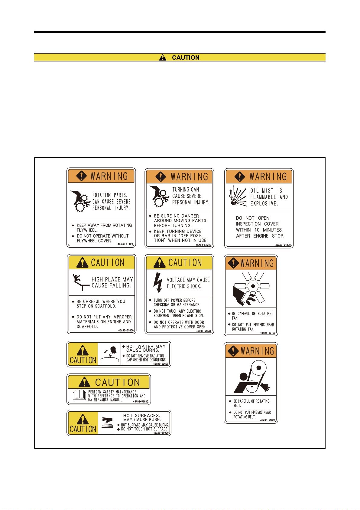
Warning Labels
Maintenance of Warning Labels
Make sure all warning/caution labels are legible.
Clean or replace the warning or caution label when the description or illustration is not clear to read.
For cleaning the warning/caution labels, use a cloth, water and soap. Do not use cleaning solvent, gasoline or other
chemicals to prevent the label from fading and peering.
Replace a damaged or missing label with a new one.
If any engine part sticked with a warning label is replaced with a new one, attach a new identical warning label to the
new part.
To get new warning labels, contact our approved dealer.
XII
Warning labels
Page 14

Points on Disassembling and Assembling
This service manual contains the recommended practices to
service the engine. The manual also contains dedicated spe-
cial tools made for the work, and the basic safety cautions to
obey when working. Note that this manual does not cover
all potential hazards that could occur during maintenance,
inspection and service works of the engine.
When working on the engine, follow the related instructions
in this manual and also be careful of the following:
Points on Disassembling
Use correct tools and instruments. Or serious damage or
accident may result.
Do not use jack bolts having sharp edge, as they may cause
damage to the surface.
Use a footing and workbench to place disassembled parts if
necessary, and obey the disassembling procedures
described in this manual. Do not place the parts on the
floor directly. Place them on a workbench or the like.
Place the engine parts in the order of removal to prevent
from missing. Place the parts in the serial order for reas-
sembling.
When reusing the engine parts, unless there are special rea-
sons, install them to their original positions.
Pay attention to assembling marks. Put your marks on the
parts, if necessary, to ensure correct assembling.
Carefully check each part for defects during disassembling
or cleaning. Do not miss symptoms which can not be
found after disassembling or cleaning.
Pay attention to the safety, especially for the balancing of
disassembled parts and carrying of heavy parts. (Get help,
and use jacks, chain blocks and guide bolts as necessary.)
Use protective gloves when you touch overheated or fro-
zen parts. Touching the part with a bear hand can cause
burns.
Points on Assembling
Wash all engine parts, except such parts as oil seals, O-
rings and rubber seats, in cleaning oil and dry them with
compressed air.
Use correct tools and instruments.
Use only high-quality lubricating oil and grease of the
appropriate type. Be sure to apply oil, grease or adhesive
to specified surfaces.
Use a torque wrench to tighten parts correctly when their
tightening torques are specified. Refer to "Tightening
torque table."
Replace Gaskets, packings and O-rings with new ones.
Apply adhesive as required. Do not apply adhesive too
much.
Use protective gloves when you touch overheated or fro-
zen parts. Touching the part with a bear hand can cause
burns.
FOREWORD
XIII
Page 15
GENERAL CONTENTS
Chapter 1 GENERAL
1. External View
2. Outline of Systems
3. Contents of Plate and Label
4. Specifications
Chapter 2 SERVICE DATA
1. Maintenance Service Data
2. Tightening Torque Table
Chapter 3 SERVICE TOOLS
1. Special Tools
Chapter 4 OVERHAUL INSTRUCTIONS
1. Determining Overhaul Timing
2. Compression Pressure - Measure
Chapter 5 DISASSEMBLY OF BASIC ENGINE
1. Cylinder Heads and Valve Mechanisms - Disassemble and Inspect
2. Rear Mechanism - Disassemble and Inspect
3. Front Mechanism - Disassemble and Inspect
4. Cylinder Liner, Piston and Connecting Rod - Disassemble and Inspect
5. Crankcase, Crankshaft and Main Bearing - Disassemble and Inspect
Chapter 6 INSPECTION AND REPAIR OF BASIC ENGINE
1. Cylinder Head and Valve Mechanism - Inspect and Repair
2. Rear Mechanism - Inspect and Repair
3. Front Mechanism - Inspect and Repair
4. Piston and Connecting Rod - Inspect and Repair
5. Crankcase and Crankshaft - Inspect and Repair
Chapter 7 ASSEMBLY OF BASIC ENGINE
1. Crankshaft and Main Bearing - Install
2. Cylinder Liner, Piston and Connecting Rod - Assemble
3. Front Mechanism - Assemble
4. Rear Mechanism - Assemble
5. Cylinder Head and Valve Mechanism - Assemble
Page 16

Chapter 8 FUEL SYSTEM
1. Fuel System - Remove and Inspect
2. Fuel System - Disassemble, Inspect and Assemble
3. Fuel System - Install
Chapter 9 LUBRICATION SYSTEM
1. Lubrication System - Remove and Inspect
2. Lubrication System - Disassemble, Inspect and Assemble
3. Lubrication System - Install
Chapter 10 COOLING SYSTEM
1. Cooling System - Remove and Inspect
2. Cooling System - Disassemble, Inspect and Assemble
3. Cooling System - Install
Chapter 11 INLET AND EXHAUST SYSTEMS
1. Inlet and Exhaust Systems - Remove and Inspect
2. Inlet and Exhaust Systems - Disassemble, Inspect and Assemble
3. Inlet and Exhaust Systems - Install
Chapter 12 AIR START SYSTEM
1. Air Start System - Remove and Inspect
2. Air Start System - Disassemble, Inspect and Assemble
3. Air Start System - Install
Chapter 13 ADJUSTMENT AND OPERATION
1. Engine - Adjust
2. Break-in Operation
3. Engine-Test and Adjustment
Page 17

Chapter 1 GENERAL
1. External View ...........................................................................................................1-3
2. Outline of Systems................................................................................................1-13
2.1 Outline of Fuel System ........................................................................................................... 1-13
2.2 Outline of Lubrication System................................................................................................. 1-13
2.3 Outline of Cooling System ...................................................................................................... 1-14
2.4 Outline of Inlet and Exhaust System....................................................................................... 1-17
3. Contents of Plate and Label .................................................................................1-19
3.1 Name Plate ............................................................................................................................. 1-19
3.2 Caution Plate .......................................................................................................................... 1-19
3.3 Emissions Certification Label.................................................................................................. 1-19
4. Specifications ........................................................................................................1-20
1-1
Page 18
Chapter 1 GENERAL
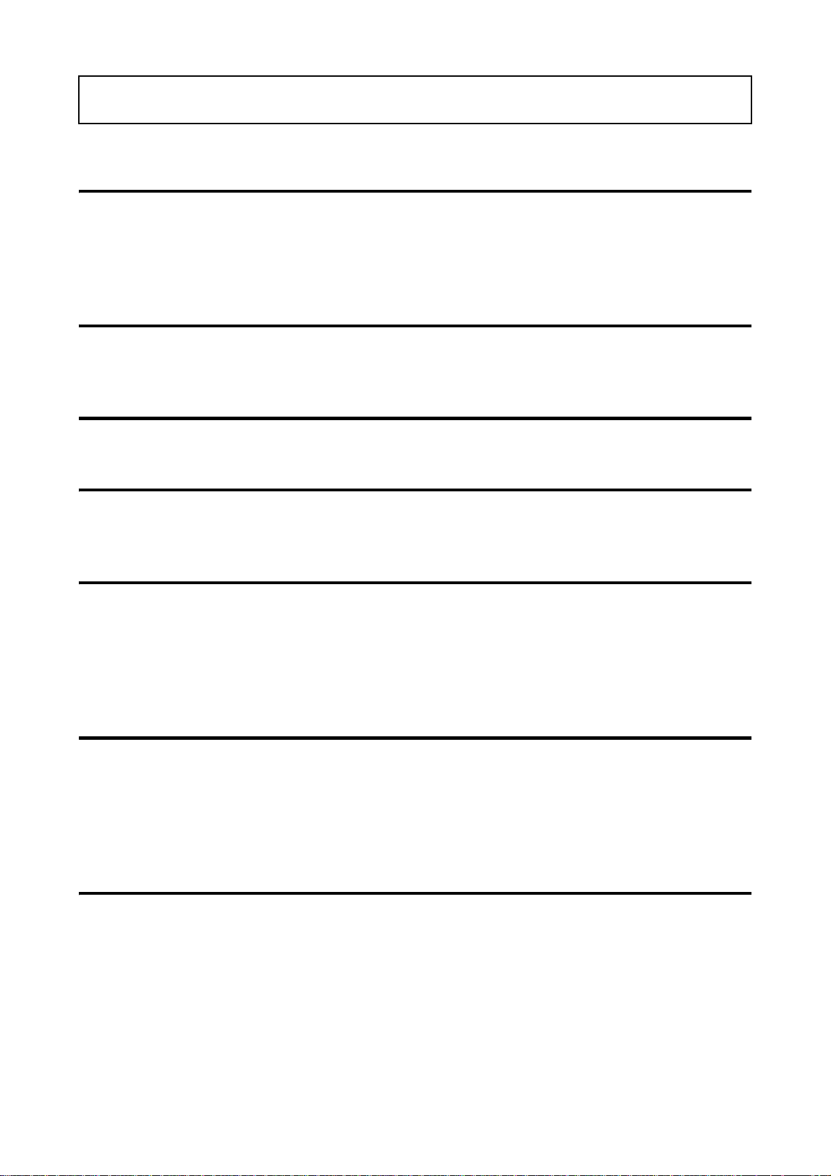
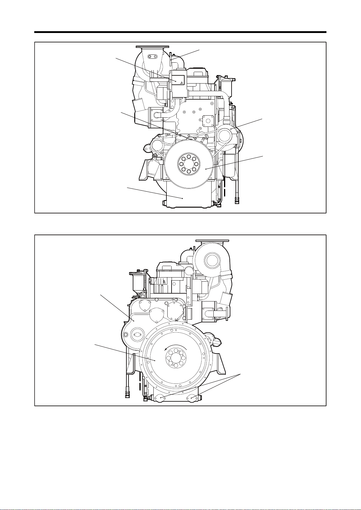
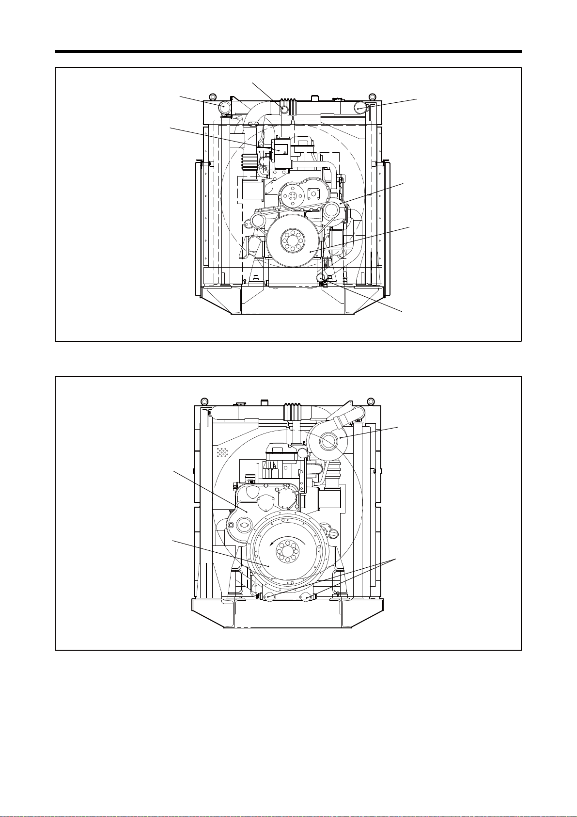
Tension pulley
Engine coolant outlet
Water pump
S6R-PTA with fan spec
Thermostat case
Oil pan
Note: Configuration varies depending on the destination and specifications.
Damper
Flywheel
Engine oil discharge port
Rotation direction
Rotation direction
Timing gear case
S6R-PTA with fan spec
Note: Configuration varies depending on the destination and specifications.
Rotation direction
1. External View
Chapter 1 GENERAL
Engine Front View
Engine Rear View
1-3
Page 19
Chapter 1 GENERAL
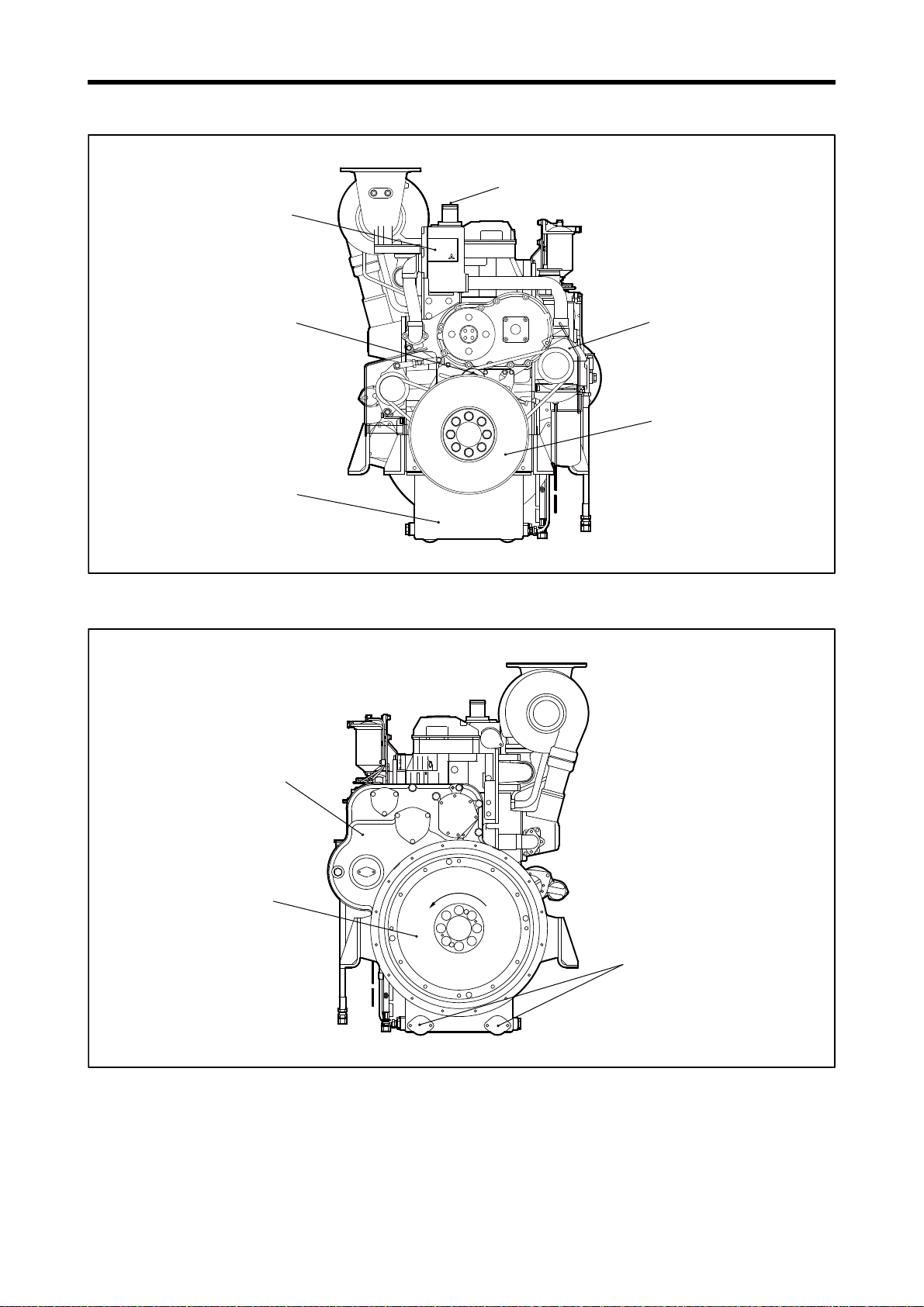
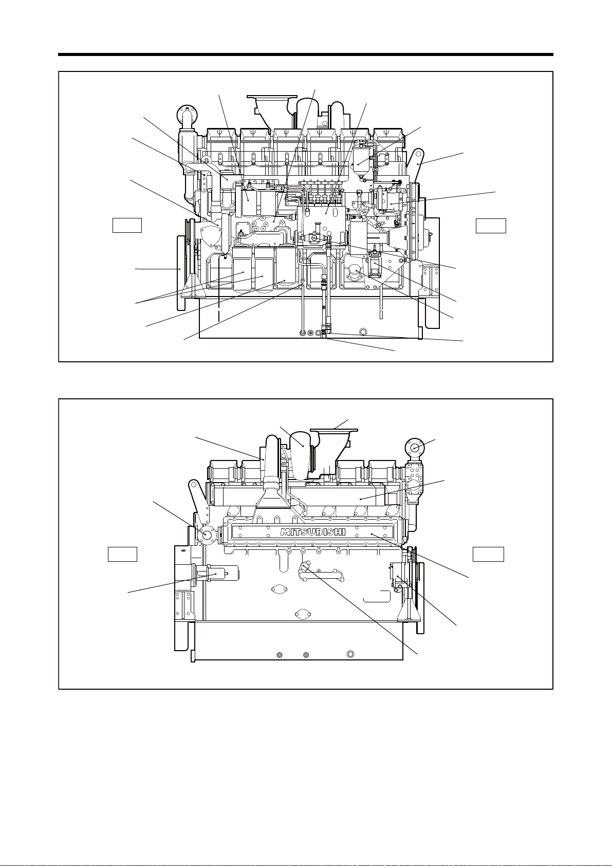
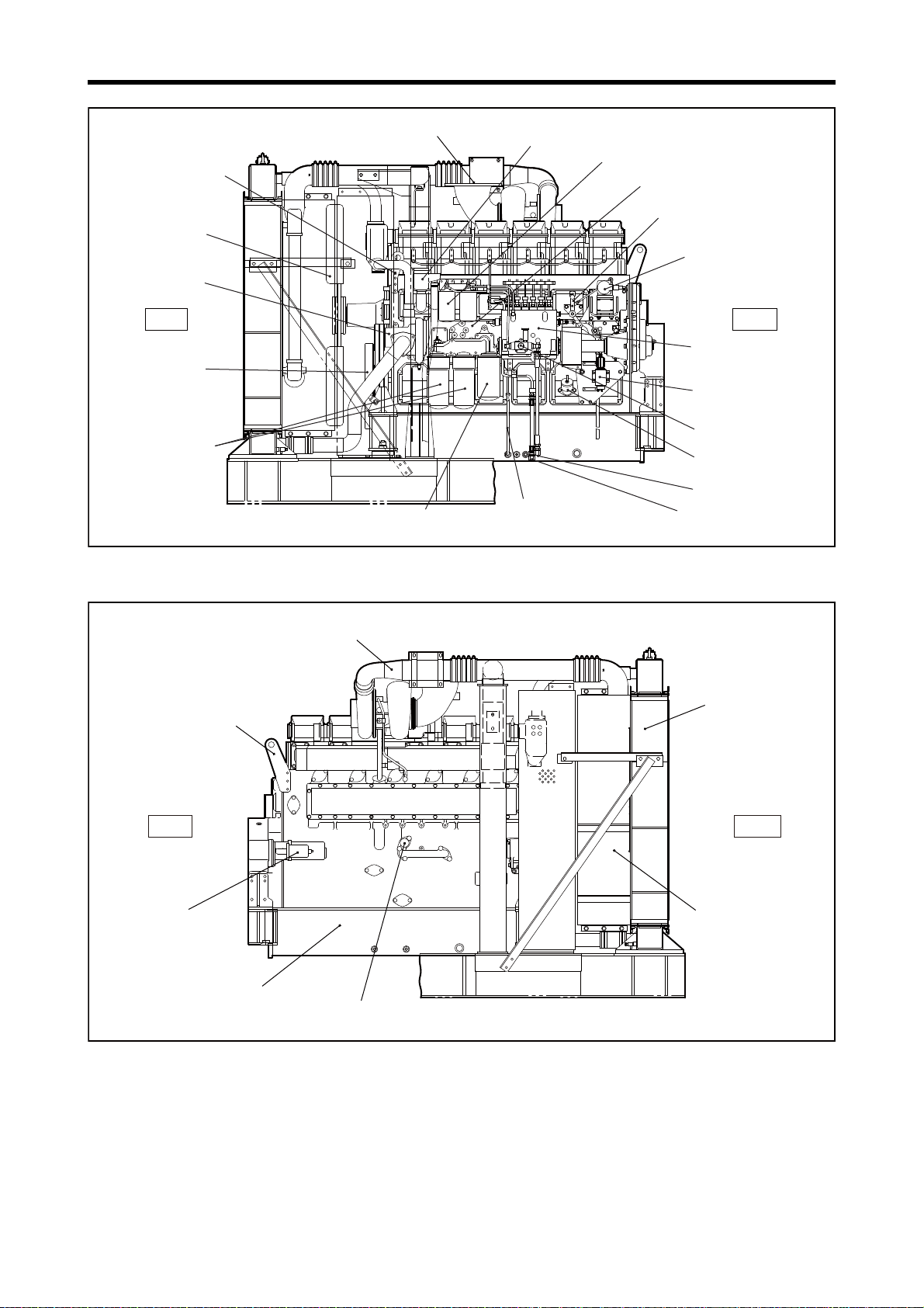
Oil level gauge
Governor
Governor oil filter
Fuel injection pump
Fuel filter
Oil cooler
Engine coolant inlet
Oil filler
Stop solenoid
Fuel outlet
Fuel inlet
Rear
Front
Damper
Oil filter
Bypass oil filter
Front hanger
Fuel feed pump
Breather
Rear hanger
Water pump
S6R-PTA with fan spec
Note: Configuration varies depending on the destination and specifications.
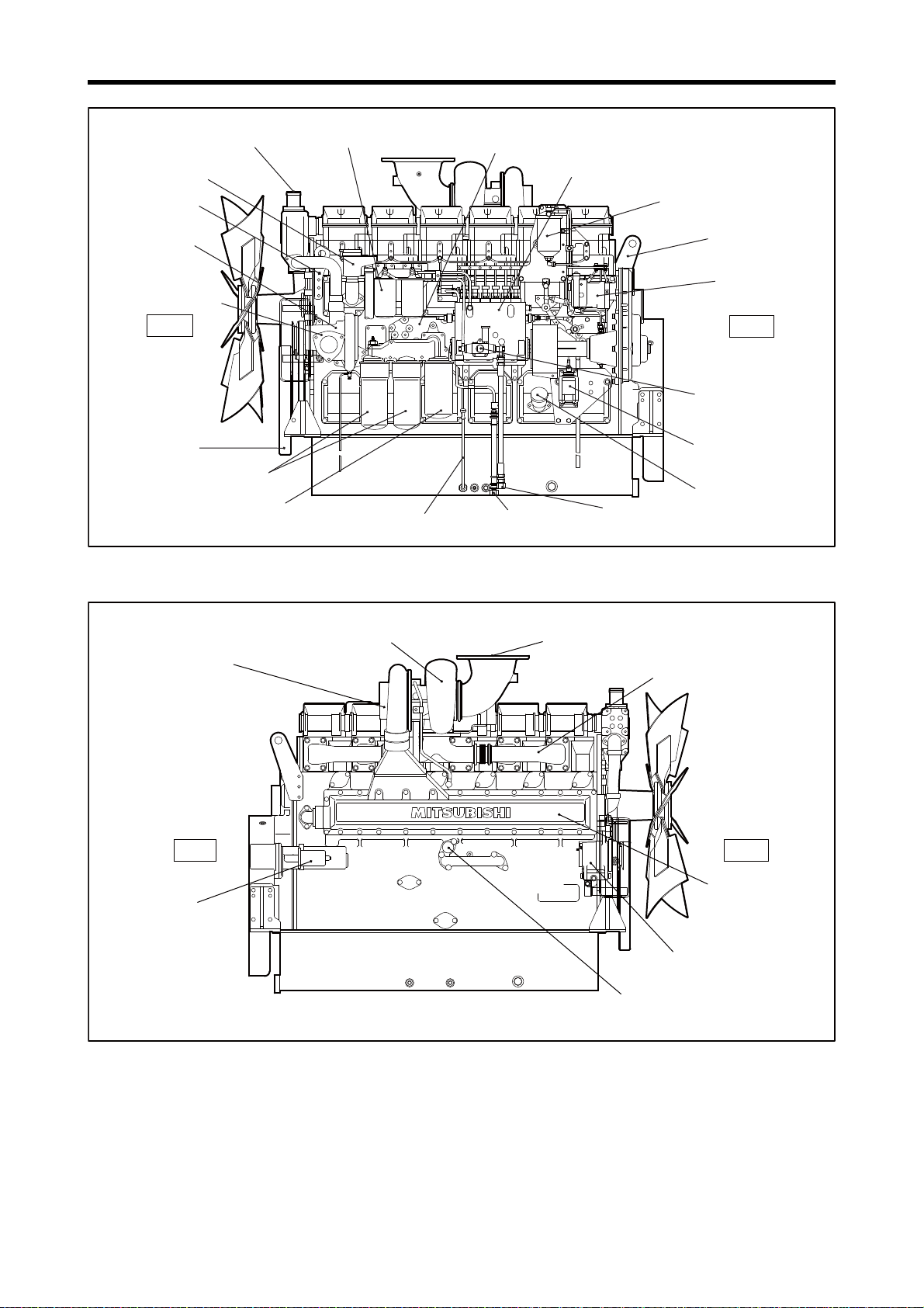
Engine coolant outlet
Starter
Air cooler
Turbocharger
Front
Rear
Air inlet
Exhaust manifold
Exhaust pipe, exhaust outlet
Relief valve
Alternator
S6R-PTA with fan spec
Note: Configuration varies depending on the destination and specifications.
Left Side View
1-4
Right Side View
Page 20
Chapter 1 GENERAL
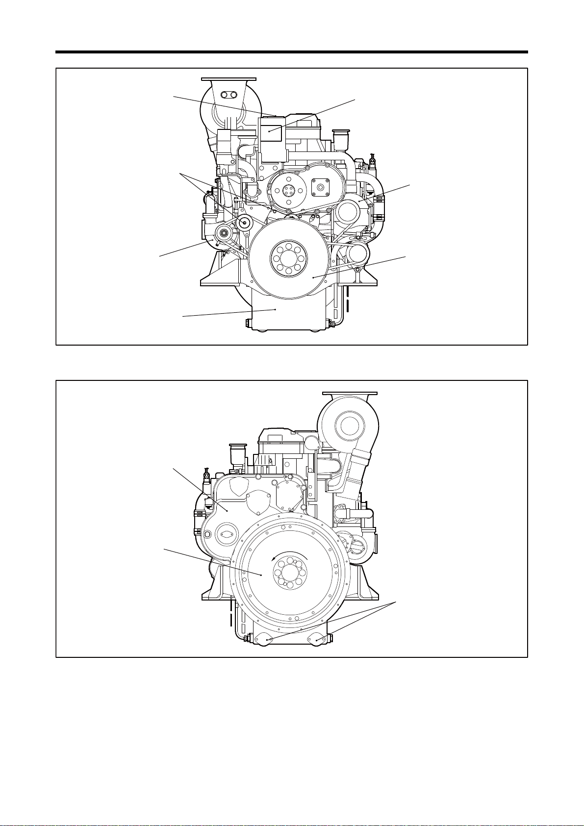
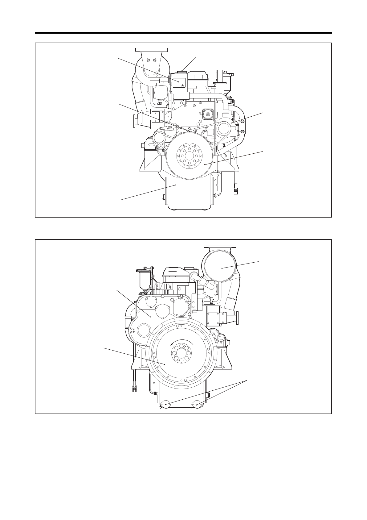
Tension pulley
Engine coolant outlet
Thermostat case
Oil pan
S6R-PTK
Note: Configuration varies depending
on the destination and specifications.
Water pump
Damper
Flywheel
Timing gear case
Note: Configuration varies depending
on the destination and specifications.
S6R-PTK
Engine oil drain port
Rotation directionRotation directionRotation direction
Engine Front View
Engine Rear View
1-5
Page 21
Chapter 1 GENERAL
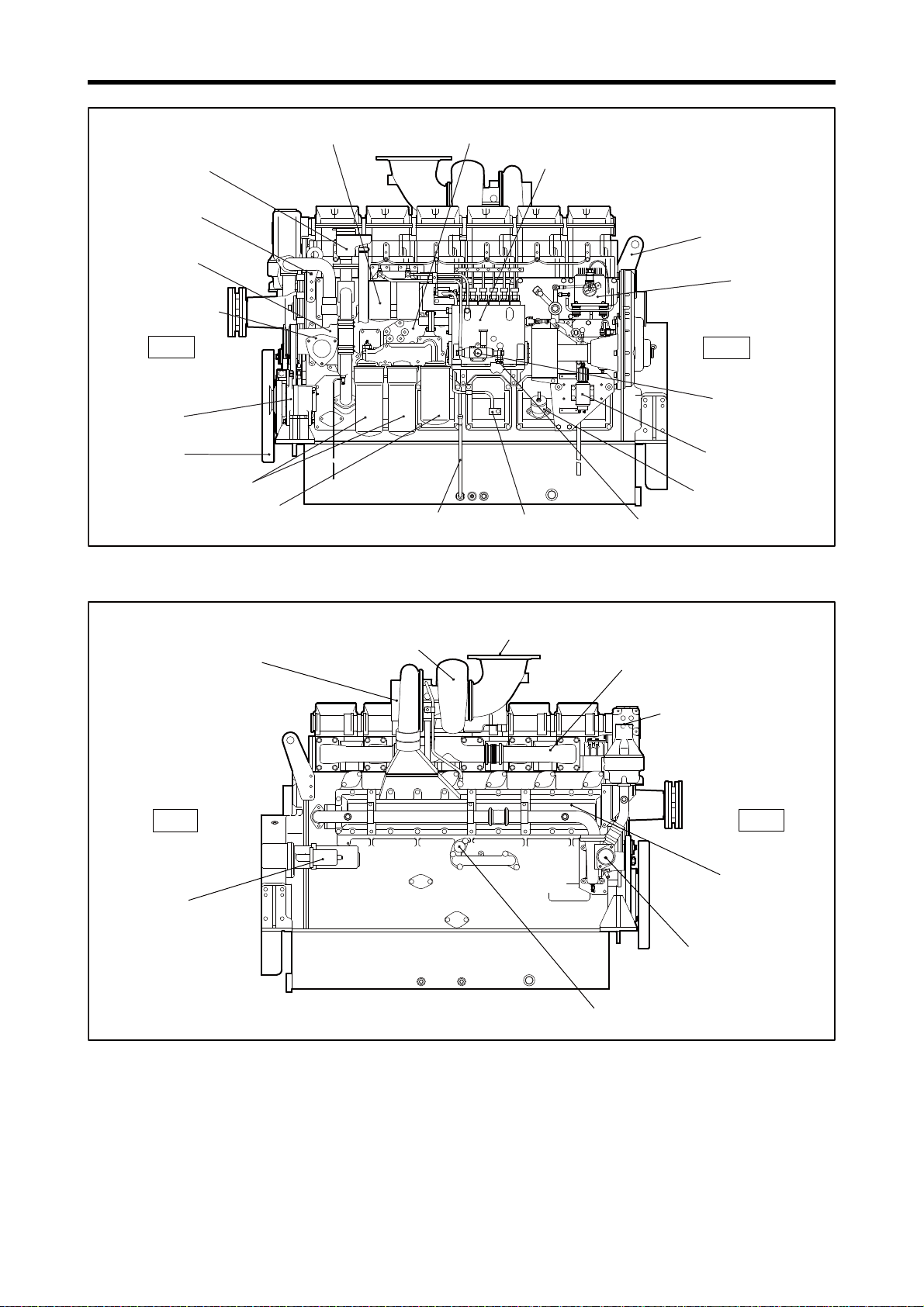
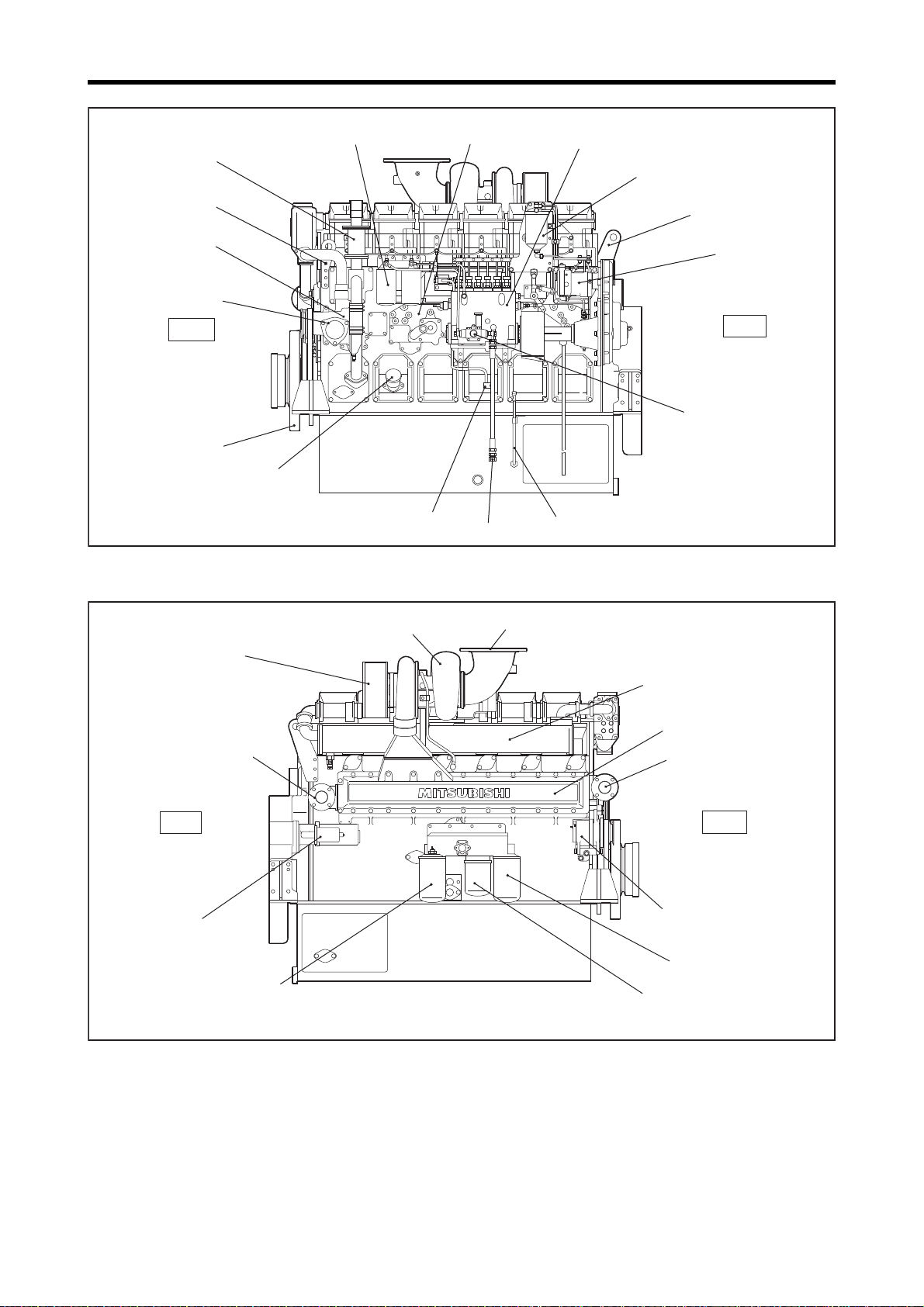
Governor
Governor oil filter
Fuel injection pump
Fuel filter
Oil cooler
Oil filler
Rear
Front
Front hanger
Breather
Rear hanger
Water pump
Note: Configuration varies depending on the destination and specifications.
S6R-PTK
Fuel feed pump
Stop solenoid
Oil level gauge
Fuel return port
Fuel inlet
Damper
Oil filter
Bypass oil filter
Starter
Engine air cooler
coolant outlet
Air cooler
Engine air cooler
coolant inlet
Turbocharger
Front
Rear
Exhaust manifold
Alternator
S6R-PTK
Note: Configuration varies depending on the destination and specifications.
Exhaust pipe, exhaust outlet
Air inlet
Relief valve
Left Side View
Right Side View
1-6
Page 22
Chapter 1 GENERAL
Tension pulley
Engine coolant outlet
Thermostat case
Oil pan
Note: Configuration varies depending on the destination and specifications.
S6R-Y2PTAW
Water pump
Damper
Water pump
for air cooler cooling
Flywheel
Timing gear case
S6R-Y2PTAW
Note: Configuration varies depending on the destination and specifications.
Engine oil drain port
Rotation directionRotation direction
Rotation direction
Engine Front View
Engine Rear View
1-7
Page 23
Chapter 1 GENERAL
Oil level gauge
Governor
Fuel injection pump
Fuel filter
Oil cooler
Engine coolant inlet
Oil filler
Fuel return port
Fuel inlet
Rear
Front
Front hanger
Breather
Rear hanger
Water pump
S6R-Y2PTAW
Note: Configuration varies depending on the destination and specifications.
Fuel feed pump
Stop solenoid
Damper
Oil filter
Bypass oil filter
Alternator
Starter
Air cooler coolant outlet
Air cooler
Turbocharger
Front
Rear
Exhaust manifold
S6R-Y2PTAW
Note: Configuration varies depending on the destination and specifications.
Exhaust pipe, exhaust outlet
Air inlet
Relief valve
Air cooler coolant inlet
Left Side View
Right Side View
1-8
Page 24
Chapter 1 GENERAL
Thermostat case
Note: Configuration varies depending on the destination and specifications.
S6R2-PTAA
Water pump
Damper
Coolant inlet
Coolant outlet
Air outlet for air cooler
Air inlet for air cooler
Flywheel
Timing gear case
S6R2-PTAA
Note: Configuration varies depending on the destination and specifications.
Engine oil drain port
Rotation directionRotation direction
Rotation direction
Turbocharger
Engine Front View
Engine Rear View
1-9
Page 25
Chapter 1 GENERAL
Fuel return port
Oil level gauge
Fuel inlet
Breather
Stop lever
Actuator (governor)
Fuel injection pump
Fuel feed pump
Stop solenoid
Water pump
Damper
Bypass oil filter
Oil filter
Oil filler
Oil cooler
Fuel filter
Fan
Front hanger
Front
Rear
Exhaust pipe, exhaust outlet
S6R2-PTAA
Note: Configuration varies depending on the destination and specifications.
Starter
Relief valve
Radiator
Air cooler
Air duct
Front
Rear
Rear hanger
S6R2-PTAA
Note: Configuration varies depending on the destination and specifications.
Oil pan
Left Side View
Right Side View
1-10
Page 26
Chapter 1 GENERAL
Tension pulley
Thermostat case
Oil pan
Water pump
Damper
Note: Configuration varies depending on the destination and specifications.
S6R-Z3MPTAW
Engine coolant outlet
Flywheel
Timing gear case
Silencer
S6R-Z3MPTAW
Note: Configuration varies depending on
the destination and specifications.
Engine oil drain port
Rotation directionRotation directionRotation direction
Engine Front View
Engine Rear View
1-11
Page 27
Chapter 1 GENERAL
Oil level gauge
Governor
Governor oil filter
Fuel injection pump
Fuel filter Oil cooler
Engine coolant inlet
Oil filler
Fuel return port
Fuel inlet
Rear
Front
Damper
Front hanger
Fuel feed pump
Breather
Rear hanger
Water pump
S6R-Z3MPTAW
Note: Configuration varies
depending on the destination
and specifications.
Starter
Oil filter
Oil filter
Bypass oil filter
Air cooler coolant outlet
Air cooler
Air cooler coolant inlet
Turbocharger
Front
Rear
Pre-cleaner air inlet
Exhaust manifold
Exhaust pipe, exhaust outlet
Alternator
S6R-Z3MPTAW
Note: Configuration varies depending on the destination and specifications.
Left Side View
1-12
Right Side View
Page 28
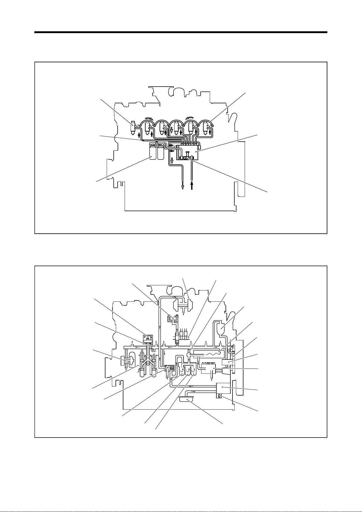
2. Outline of Systems
Fuel injection nozzle
Fuel leak-off pipe
Fuel injection pump
Fuel feed pump
From fuel tank
To fuel tank
Fuel filter
Fuel injection pipe
Oil pressure governor spec
Governor
Turbocharger
Camshaft
Oil thermostat
Oil cooler
Timing gear
Fuel injection pump
Oil pump
Safety valve
Bypass oil filter
Oil strainer
Oil filter
Relief valve
Crankshaft
Water pump
Piston
cooling nozzle
Piston
Rocker shaft
Oil filter
Governor oil filter
2.1 Outline of Fuel System
Chapter 1 GENERAL
2.2 Outline of Lubrication System
Outline of Fuel System
Outline of Lubrication System
1-13
Page 29
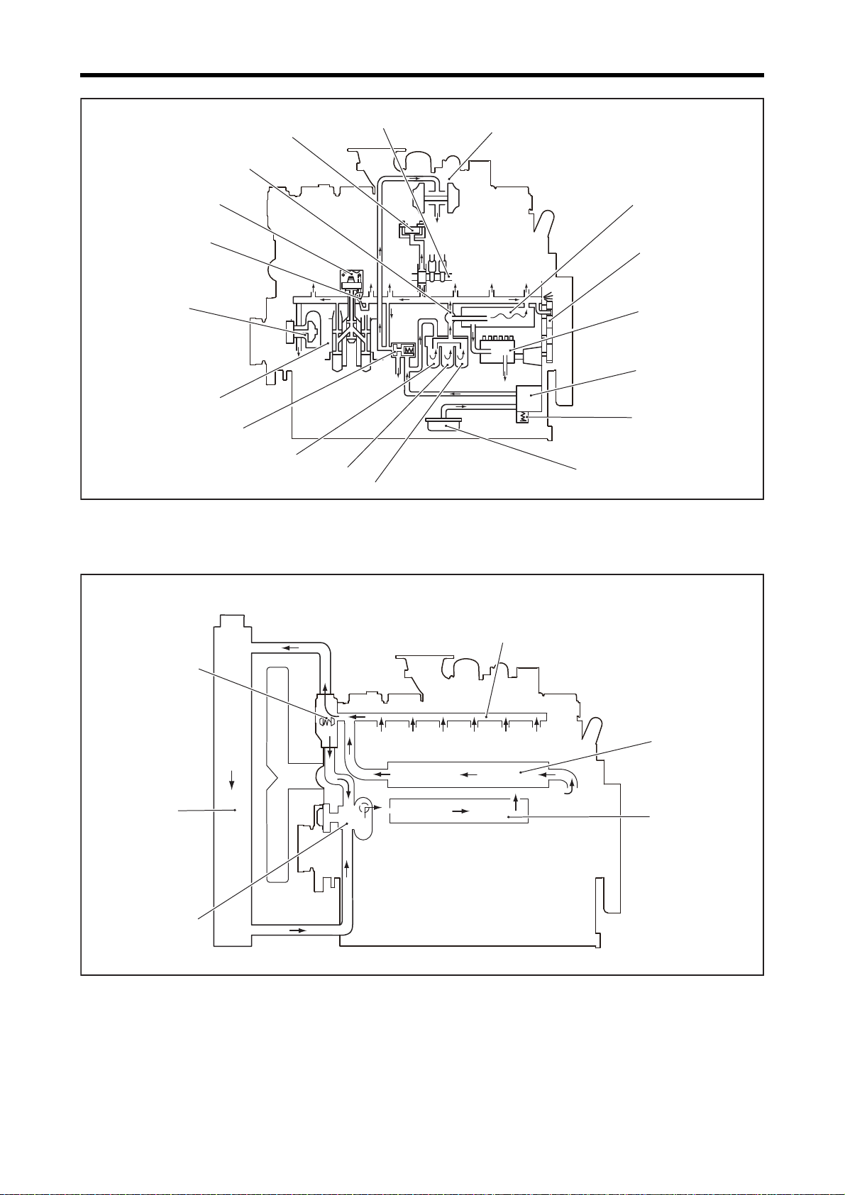
Chapter 1 GENERAL
Turbocharger
Camshaft
Oil thermostat
Oil cooler
Electronic governor spec
Timing gear
Fuel injection pump
Oil pump
Safety valve
Bypass oil filter
Oil strainer
Oil filter
Relief valve
Crankshaft
Water pump
Piston
cooling nozzle
Piston
Rocker shaft
Oil filter
Water outlet pipe (rocker case)
Oil cooler
Air cooler
PTA spec
Thermostat
Radiator
Water pump
2.3 Outline of Cooling System
Outline of Lubrication System
1-14
Outline of Cooling System
Page 30
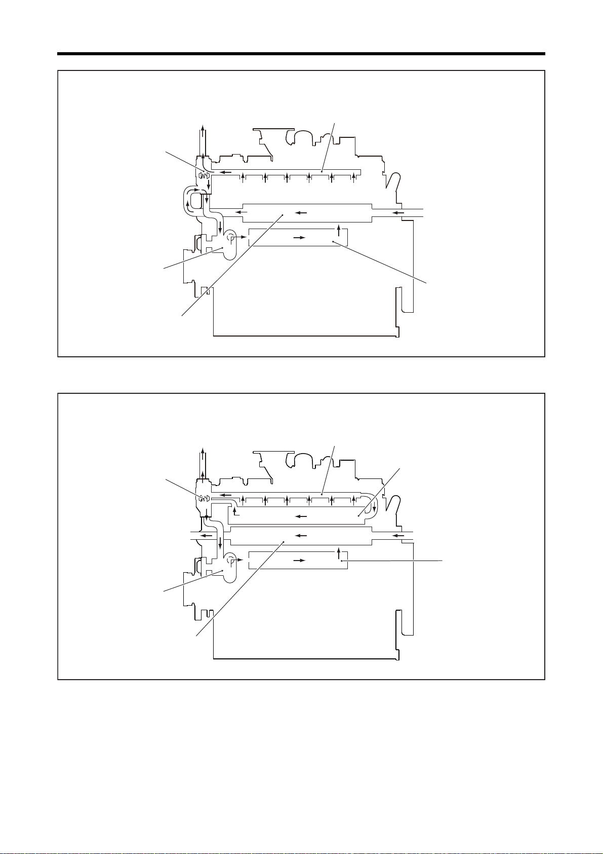
Chapter 1 GENERAL
Water outlet pipe (rocker case)
Oil cooler
PTK spec
Thermostat
Air cooler
Water pump
Air cooler,
Engine coolant inlet
Air cooler,
engine coolant outlet
Water outlet pipe (rocker case)
Oil cooler
PTAW spec (Outside of water pump for air cooler cooling)
Thermostat
Air cooler
Water pump
Exhaust manifold
Air cooler coolant inlet Air cooler coolant outlet
Engine coolant outlet
Outline of Cooling System
Outline of Cooling System
1-15
Page 31

Chapter 1 GENERAL
Water outlet pipe (rocker case)
Oil cooler
Thermostat
Air cooler
Water pump
Air cooler water pump
Engine coolant inlet
Air cooler coolant outlet
Engine coolant
outlet
Air cooler
coolant outlet
PTAW spec (Water pump for air cooler cooling mounted)
Water outlet pipe (rocker case)
Oil cooler
Air cooler
PTAA spec
Thermostat
Radiator
Water pump
Outline of Cooling System
1-16
Outline of Cooling System
Page 32

Chapter 1 GENERAL
Water outlet pipe (rocker case)
Oil cooler
Marine gear
oil cooler
MTK, MPTK spec
Thermostat
Heat exchanger
Water pump
Sea water pump
Sea water
outlet port
Sea water inlet port
Exhaust manifold
Exhaust outlet
Air cooler
Exhaust air
Charging air
Turbocharger
Exhaust pipe
Internal air cooler spec
From air-cleaner
Cylinder
2.4 Outline of Inlet and Exhaust System
Outline of Cooling System
Outline of Inlet and Exhaust System
1-17
Page 33

Chapter 1 GENERAL
Exhaust outlet
Air cooler
Exhaust air
Charging air
Turbocharger
Exhaust pipe
External air cooler spec
From air-cleaner
Cylinder
Outline of Inlet and Exhaust System
1-18
Page 34

3. Contents of Plate and Label
3.1 Name Plate
The name plate is attached on the lateral side of the engine,
and shows the following information:
Engine serial number
Manufactured date
Total displacement
Engine output
Rated speed
Right side
Chapter 1 GENERAL
RearFront
3.2 Caution Plate
The caution plate is attached to the top face of the rocker
cover of No. 1 cylinder and shows the following informa-
tion:
Valve clearance
Firing order
Fuel injection timing
Connecting rod weight rank
3.3 Emissions Certification Label
The emission certification label that shows compliance with
emission requirements is attached to the engine.
Left side
Cylinder No.
Name Plate
VALVE CLEARANCE(COLD)
INLET
FUEL INJECTION TIMING
mm
0.6
FIRING ORDER
1-5-3-6-2-4
CON-ROD RANK
EXHAUST
0.8
mm
°
BTDC
Caution Plate
1-19
Page 35

Chapter 1 GENERAL
4. Specifications
Engine model S6R S6R2
Type Water cooled, four stroke cycle diesel, turbo charged
No. of cylinders - Arrangement 6 cylinders, in-line
Combustion system Direct injection system
Valve mechanism Overhead
Cylinder bore × stroke 170×180 mm [6.69×7.09 in.] 170×220 mm [6.69×8.66 in.]
Total displacement 24.51 L [1495.9 cu in] 29.96 L [1828.5 cu in.]
Firing order 1-5-3-6-2-4
Direction of rotation Counterclockwise as viewed from flywheel side
Engine oil Class CF or CH-4 (API service classification)
Specification table
The mark "○" in the table represents the installed equipment of each engine type.
Note:(a) This table shows the general information. The installation of equipment differs in accordance with the customization
and specifications.
(b) The specification and part number may be changed with the design progress without prior notice.
Equipment name Specification name
Single spring
Valve mechanism
Camshaft
Cylinder liner
Piston
cooling nozzle
Oil pan
Connecting rod
Rod
(Inlet side)
Double spring
(Exhaust side)
Overlap 61°
(37505-40100)
Overlap 93°
(37505-34100)
Overlap 93° advanced by 4°
(37505-04300)
(37507-22700) ○○○○○○○○○○○○○○○○
(37507-55600) ○○○○○○○○○○○○
One jet ○○○ ○○○○○○○○○○○○○○○○○○○○○○
Two jets ○○○○
Standard oil pan
(37513-60101)
Deep type oil pan
(Hi 145L, Low114L)
[38.3, 30.1 USgal]
(37513-20602)
Bolt identification mark
"AU""AL"
(37519-31020)
Bolt identification mark "2"
(37519-75020 to 76010)
S6R S6R2
V2PTK-1
Y2PTAW
Y1PTA-4
Y1PTA-5
PTA-S
PTA
PT
○○○○○○○○○○○○○○○○○○○○○○○○○○○○
○ ○○○○○ ○ ○ ○○○
○○○ ○ ○○ ○○○ ○○○○○○○○○○
○ ○○○○○ ○ ○ ○ ○
○○○○○○○○○○ ○○○○○○○○
○ ○ ○○○○○○○ ○ ○○○○○○○
○○○○○○○○○○○○○○○○
PTK
TA
Z3MPTAW
MPTA
Y1MPTA-3
Y1MPTK-3
MPTK
Y2MPTK-3
MPT
PTA
PT
○○○○○○○○○○○○
PTAA
PTA-S
PTAA-S
PTK
MPTA
MPTK
MTK
MTK2
MTK3
○○
MTK2L
1-20
Page 36

Chapter 1 GENERAL
Equipment name Specification name
Overlap 61°
Compression ratio 14
(37517-30101)
Overlap 93°
Compression ratio 15
(37517-10401)
Overlap 93°
Compression ratio 14.5
(37517-00900)
Piston
Flywheel
Front pulley,
Crankshaft pulley
Overlap 61°
Compression ratio 14
(37517-25100)
Overlap 91°
Compression ratio 14
(37517-05300)
Overlap 93°
4°advance, compression
ratio14
(37517-05500)
Standard (37521-00012) ○○○○○○○○ ○○○○○○
FCD spec (37521-00060) ○○○○○○○ ○○○○○○
Land clutch (37521-12012) ○
(37525-12201) ○○○○○ ○○○○○○○○○○○○○○○○○○○○○○
(37525-04501) ○
(37525-18800) ○○
(37320-22600) ○○○
(37525-28101) ○ ○○ ○○○○○○
(37525-18600) ○○
(37525-02800) ○
S6R S6R2
V2PTK-1
Y2PTAW
Y1PTA-4
Y1PTA-5
PTA-S
PTA
PT
○○○ ○ ○○ ○○○ ○
○○○○○
PTK
○○○
TA
Z3MPTAW
MPTA
Y1MPTA-3
Y1MPTK-3
MPTK
Y2MPTK-3
MPT
PTAA-S
PTA-S
PTAA
PTA
PT
○○○○○○○○○
PTK
MPTK
MPTA
MTK
MTK2L
MTK2
MTK3
○○
○○
1-21
Page 37

Chapter 1 GENERAL
Equipment name Specification name
TD10L-42F-34 ○
TD10L-42F-43 ○○○○
TD13L-47F-40 ○○○○○○○
TD13L-47F-47 ○○○○○ ○○○
TD13L-47F-55 ○○
TD13L-54QRC-47 ○○
TD13L-54QRC-47
Water cool exhaust manifold
TD13L-57V-55 ○
TD13M1-48QRC-40 ○
TD15-50B-49 ○○ ○○
TD15-50B-54 ○○○
TD15-55B-54 ○○○
Turbocharger
Fan
TD15-55B-54 Classification
JG
TD15-55B-54 Classification
NK
TD15-55B-59 ○○
TD15-55B-66 ○
TF15L-60QV-49 ○
TF15M-60QV-49 ○○○○
TF15M-60QVRC-49 ○○○
TF15M-67QVRC-49
(Flange connection type)
TF15M-67QVRC-54 ○○
TF15M1-67QVRC-49 ○
TF15M1-60QVRC-49
Water cool exhaust manifold
D1010, PUSHER
(46648-02300)
D1016, PUSHER
(46648-22600)
S6R S6R2
V2PTK-1
Y2PTAW
Y1PTA-4
Y1PTA-5
PTA-S
PTA
PT
○○○○ ○○ ○○○ ○ ○
PTK
TA
Z3MPTAW
MPTA
○
○
Y1MPTA-3
Y1MPTK-3
MPTK
Y2MPTK-3
MPT
PT
PTA-S
PTAA
PTA
○○
PTAA-S
PTK
MPTA
MPTK
○
○
MTK
MTK2
MTK3
○○
MTK2L
1-22
Page 38

Chapter 1 GENERAL
Equipment name Specification name
Fresh water (internal cooling)
air cool exhaust manifold
(37555-30030)
Fresh water
(external cooling)
air cool exhaust manifold
(37555-30040)
Fresh water (internal cooling)
Water cool exhaust manifold
(37555-10054)
Sea water (37555-30083) ○○ ○○
Air cooler
Fuel injection
nozzle
Fresh water (internal cooling)
air cool exhaust manifold
Classification JG
(37555-30J30)
Fresh water (two system)
air cool exhaust manifold
(37555-30030)
Fresh water (two system)
Water cool exhaust manifold
(37555-00060)
MTK2(37555-33013) ○○
MTK3(37555-05012) ○○
MPTK(37555-30083) ○
T model, screw adjust
opening pressure type
(37560-35000)
T model, screw adjust
opening pressure type
(37560-37000)
T model, screw adjust
opening pressure type
(37560-39000)
T model, screw adjust
opening pressure type
(37560-22010)
T model, screw adjust
opening pressure type
(37560-41000)
T model, screw adjust
opening pressure type
(37561-44000)
T model, shim adjust
opening pressure type
(37560-32000)
TE model, screw adjust
opening pressure type
(37860-06000)
S model, screw adjust
opening pressure type
(37760-22001)
S6R S6R2
V2PTK-1
Y2PTAW
Y1PTA-4
Y1PTA-5
PTA-S
PTA
PT
○○○○ ○○ ○○ ○ ○
○○○○○
○○ ○ ○ ○
○ ○ ○○ ○○○ ○○○ ○○○○
○○ ○○○○○○ ○○○
PTK
○○ ○
○
○○
Z3MPTAW
MPTA
TA
○○ ○
○○
○○
Y1MPTA-3
Y1MPTK-3
MPTK
Y2MPTK-3
MPT
PT
○
PTAA-S
PTA-S
PTAA
PTA
○
MPTK
MPTA
PTK
○○○○
MTK
MTK2
MTK2L
MTK3
○
1-23
Page 39

Chapter 1 GENERAL
Equipment name Specification name
Diesel oil ○○○○○○○○ ○ ○○ ○○○○
Diesel oil, changover type ○○ ○ ○○
Fuel filter
Governor
Starter
Alternator
Stop solenoid
Start restriction
solenoid
A diesel oil ○○ ○○○○○○○○○○○○○
Diesel oil, changeover type ○○ ○○
Primary filter ○○ ○
Changeover type (VOLVO) ○○
Woodward make
PSG type governor
Woodward make
SG type governor
TOHO SEISAKUSHO Co.,
LTD .
SG4017 type actuator
Woodward make
DYNA8000 type Actuator
Woodward make
PROACT type Actuator
Land use self starter motor
(37566-30200)
Land use self starter motor
(37566-40300)×2
Marine use self starter motor
(37566-45200)
Marine use self starter motor
(37566-45200)×2
Air motor (04065-61001) ○○○
30A (04343-38000) ○○○○○○○○ ○○○○○○
35A, brushless
(04343-35500)
35A, brushless, JG
(04343-35600)
35A, JG (04344-05100) ○ ○ ○ ○ ○○○○
130A (04344-08001) ○
RUN-OFF ○○ ○ ○○○○○○○○○○ ○○○○○○○
RUN-ON ○○○○○○○ ○○○○○
RUN-OFF ○○
S6R S6R2
V2PTK-1
Y2PTAW
Y1PTA-4
Y1PTA-5
PTA-S
PTA
PT
○○ ○ ○○○○○○○ ○○ ○○○○○○○
○○ ○ ○○○○○
○○
○○○○
○○○○○○○○○ ○○○○○○
○ ○○ ○○○ ○○
PTK
Z3MPTAW
MPTA
TA
○○ ○
○○○○○○○ ○○○○○○
○○○ ○○
Y1MPTA-3
Y1MPTK-3
MPTK
Y2MPTK-3
MPT
PT
PTAA-S
PTA-S
PTAA
PTA
PTK
MPTK
MPTA
MTK
○
MTK2
MTK3
MTK2L
1-24
Page 40

Chapter 2 SERVICE DATA
1. Maintenance Service Data ......................................................................................2-3
1.1 Maintenance Service Data of Engine General.......................................................................... 2-3
1.2 Maintenance Service Data of Basic Engine.............................................................................. 2-4
1.3 Maintenance Service Data of Fuel System............................................................................... 2-9
1.4 Maintenance Service Data of Lubrication System .................................................................. 2-11
1.5 Maintenance Service Data of Cooling System ....................................................................... 2-12
1.6 Maintenance Service Data of Electrical System ..................................................................... 2-14
1.7 Air Start System...................................................................................................................... 2-17
2. Tightening Torque Table.......................................................................................2-18
2.1 Tightening Torque Spec for Basic Engine .............................................................................. 2-18
2.2 Tightening Torque Spec for Fuel System ............................................................................... 2-19
2.3 Tightening Torque Spec for Lubrication System..................................................................... 2-19
2.4 Tightening Torque Spec for Cooling System.......................................................................... 2-20
2.5 Tightening Torque Spec for Inlet and Exhaust System .......................................................... 2-20
2.6 Tightening Torque Spec for Electrical System........................................................................ 2-21
2.7 Tightening Torque Spec for Air Start System ......................................................................... 2-21
2.8 Tightening Torque for Standard Bolts..................................................................................... 2-22
2.9 Tightening Torque for Standard Eyebolts ............................................................................... 2-23
2.10 Tightening Torque for Standard Union Nuts........................................................................... 2-23
2.11 Tightening Torque for Fuel Injection Pipe............................................................................... 2-23
2-1
Page 41

Chapter 2 SERVICE DATA
1. Maintenance Service Data
1.1 Maintenance Service Data of Engine General
Item
Compression pressure
At rated
Engine oil pressure
When idling
Open BTDC 37°
Close ABDC 44°
Open BBDC 57°
Close ATDC 24°
Open BTDC 2.5°
Close BBDC 13°
Open BBDC 26°
Close BTDC 10.5°
Open BTDC 53°
Close ABDC 44°
Open BBDC 57°
Close ATDC 40°
Open BTDC 14°
Close ABDC 12.5°
Open BBDC 25.5°
Close ATDC 1°
Open BBDC 57°
Close ABDC 40°
Open BBDC 61°
Close ABDC 36°
Open BTDC 18°
Close ABDC 8.5°
Open BBDC 29.5°
Close BTDC 3°
Overlap 61°
camshaft
P/N:37505-40100
Overlap 93°
Valve timing
camshaft
P/N:37505-34100
Overlap 93°
advanced by 4°
camshaft
P/N:37505-04300
Valve clearance (when cold)
Fuel injection timing
Inlet
Exhaust
Inlet
Exhaust
Inlet
Exhaust
Inlet
Exhaust
Inlet
Exhaust
Inlet
Exhaust
Inlet 0.6 mm [0.024 in.]
Exhaust 0.8 mm [0.031 in.]
Nominal
value
Standard value Limit value Remarks
}
}
}
1.27 MPa
{13 kgf/cm2}
[189 psi]
0.29 MPa
{300 kgf/cm2}
[4267 psi]
0.15 MPa
{300 kgf/cm2}
[4267 psi]
Cranking
(approx 120 min
When oil temperature is
90 to 100º C [194 to 212°F]
1.8 MPa
{18.5 kgf/cm
2
[263 psi]
0.49 to 0.64 MPa
{300 kgf/cm
2
[4267 psi]
0.20 to 0.29 MPa
{300 kgf/cm
2
[4267 psi]
Valve clearance 0 mm
±2°(Crank angle)
Valve clearance 2 mm
[0.08 in.]
Valve clearance 0 mm
±2°(Crank angle)
Valve clearance 2 mm
[0.08 in.]
Valve clearance 0 mm
±2°(Crank angle)
Valve clearance 2 mm
[0.08 in.]
Check the caution plate on
No. 1 rocker cover.
-1
Chapter 2 SERVICE DATA
)
2-3
Page 42

Chapter 2 SERVICE DATA
B
Lf
A
B
Lf
A
B
Lf
A
1.2 Maintenance Service Data of Basic Engine
Item
Rocker bushing inside diameter ø36 [1.42]
Rockers
Rocker shaft outside diameter ø36 [1.42]
Valve stem outside diameter ø10 [0.39]
Valve guide inside diameter ø10 [0.39]
Va l ve
Clearance
Intake side
between the bottom face of valve
bridge and top
face of valve
rotator
Exhaust
side
Single valve spring spec
Double valve spring
spec
Valve seat angle 30°
Valve sinkage 0
Seat width
Valve margin
Valve seat
Inside diameter of valve seat counterbore
and valve
Standard
Valve seat outside
diameter
0.03
0.06
Valve seat interference
Free length 73 [2.87] 71 [2.80]
Single
valve
spring
P/N:
37504-10400
Squareness
Installed length/load
(mm [in.]/N {kgf} [lbf])
Free length
P/N:
37504-10600
Inner
spring
Squareness
Set length / load
Double
valve
spring
P/N:
37504-20500
Outer
spring
(mm [in.]/N{kgf} [lbf])
Free length 96.57
Squareness
Set length / load
(mm [in.]/N{kgf} [lbf])
Push rod Runout 0.50 [0.0197] or less TIR
Nominal
value
2.3
[0.091]
3.0
[0.118]
Standard value Limit value Remarks
36.000 to 36.040
[1.4173 to 1.4189]
35.966 to 35.991
[1.4160 to 1.4170]
9.940 to 9.960
[0.3913 to 0.3921]
10.000 to 10.015
[0.3937 to 0.3943]
2.1
[0.083]
36.090
[1.4209]
35.940
[1.4150]
9.910
[0.3902]
10.060
[0.3961]
Same for both inlet and
exhaust valves.
Single valve spring spec
only
3.4
[0.134]
2.1
[0.083]
- 0.1 to 0.1
[-0.004 to 0.004]
2.18 to 2.42
[0.0858 to 0.0953]
2.8 to 3.2
[0.110 to 0.126]
60.000 to 60.030
[2.3622 to 2.3634]
60.100 to 60.130
[2.3661 to 2.3673]
60.130 to 60.160
[2.3673 to 2.3685]
60.160 to 60.190
[2.3685 to 2.3697]
1.0
[0.039]
2.8
[0.110]
2.5
[0.098]
60.09
[2.3657]
Valve
seat angle
2 lines, brown
3 lines, brown
4 lines, brown
0.070 to 0.130
[0.0028 to 0.0051]
A=1.5° or less
B=1.9 [0.075] or less
Lf=73 [2.87]
B=2.2
[0.087] over
entire length
66.0 [2.60]/289 to 319
{29.45 to 32.55}
[65 to 72]
90.6
[3.567]
A=2.0° or less
B=3.2 [0.126] or less
Lf=90.6 [3.567]
88.12
[3.469]
B=3.7
[0.146] over
entire length
56.0 [2.20]/137 to 152
{14 to 15.5}
[31 to 34]
93.92
[3.8020]
A=2.5° or less
B=4.2 [0.165] or less
Lf=96.57 [3.8020]
[3.698]
B=4.9
[0.193] over
entire length
62.0 [2.44]/496 to 549
{50.6 to 56.0}
[112 to 123]
Unit: mm [in.]
Seat width
Valve
sinkage
Valve
margin
2-4
Page 43

Cylinder
head
Cylinder
liner
Piston
Cylinder
head
gasket
Piston
cooling
nozzle
Piston and
cylinder
head
Piston ring End gap
Distortion of bottom surface 0.03 [0.0012] or less
Height (reference)
Inside diameter
Roundness 0.02 [0.0008] or less
Cylindricity 0.02 [0.0008] or less
Flange protrusion
Flange thickness
Top ridge height
Outside diameter
Weight difference
per engine
Piston pin bore inside diameter ø70 [2.76]
protrusion
Thickness when tightened
Valve opening
pressure
Top clearance
Item
P/N: 37507-22700 (S6R)
P/N: 37507-55600 (S6R2)
P/N:
37517-30101 ("30101" stamp)
37517-10401 ("10401" stamp)
37517-00900 ("00900" stamp)
37517-25100 ("25100" stamp)
37517-05500 ("05500" stamp)
37517-05300 ("05300" stamp)
P/N:
37517-07800 ("07800" stamp)
37517-07900 ("07900" stamp)
P/N:
37517-00800 ("00800" stamp)
P/N:
37517-30101 ("30101" stamp)
37517-10401 ("10401" stamp)
37517-00900 ("00900" stamp)
37517-25100 ("25100" stamp)
37517-05500 ("05500" stamp)
37517-05300 ("05300" stamp)
37517-07800 ("07800" stamp)
37517-07900 ("07900" stamp)
P/N:
37517-00800 ("00800" stamp)
One jet spec
Two jet spec
No. 1 compression
No. 2 compression
Oil
Nominal
value
ø170
[6.69]
ø170
[6.69]
ø170
[6.69]
ø170
[6.69]
ø170
[6.69]
1.8
[0.071]
Chapter 2 SERVICE DATA
Unit: mm [in.]
Standard value Limit value Remarks
0.07
[0.003]
154.9 to 155.1
[6.098 to 6.106]
170.02 to 170.04
[6.6937 to 6.6945]
170.00 to 170.04
[6.6929 to 6.6945]
0.11 to 0.20
[0.0043 to 0.0079]
14.16 to 14.20
[0.5575 to 0.5591]
0.16 to 0.24
[0.0063 to 0.0094]
169.760 to 169.800
[6.6835 to 6.6850]
169.739 to 169.779
[6.6826 to 6.6842]
169.760 to 169.780
[6.6835 to 6.6842]
within 10 g [0.35 oz]
within ±15 g [0.53 oz]
70.002 to 70.015
[2.7560 to 2.7565]
0.04 to 0.64
[0.0016 to 0.0252]
1.77 to 1.83
[0.0697 to 0.0720]
0.26 to 0.32 MPa
{2.7 to 3.3 kgf/cm
[38 to 47 psi]
0.10 to 0.15 MPa
{1.0 to 1.5 kgf/cm
[14 to 21 psi]
1.24 to 1.99
[0.0488 to 0.0783]
0.6 to 0.8
[0.024 to 0.032]
0.6 to 0.8
[0.024 to 0.032]
0.3 to 0.45
[0.0118 to 0.0177]
170.100
[6.6968]
Measure the outside
169.660
[6.6795]
169.639
[6.6787]
169.660
[6.6795]
70.040
[2.7575]
2
}
2
}
1.0
[0.039]
0.6
[0.024]
diameter from lower end
of piston at 40 mm [1.57
in.] with right angles to
the piston pin.
2-5
Page 44

Chapter 2 SERVICE DATA
Item
Piston pin Outside diameter ø70 [2.76]
Inside diameter of connecting rod bushing ø70 [2.76]
Bend and twist
End play
Connecting rod
Connecting rod
rod
bearing
Flywheel
Damper
Rear mechanism
Camshaft
Inside diameter of big end bore
Roundness for inside diameter of big end bore
Big end side (Width)
Standard
0.25
Thickness at
center
Face runout (Reference) 0.285 [0.0112] or less
Radial runout (Reference) 0.127 [0.0050] or less
Face runout (Reference) 0.5 [0.0197] or less
Radial runout (Reference) 0.5 [0.0197] or less
Backlash between crank gear and idler gear
Backlash between idler gear and camshaft gear
Backlash between idler gear and fuel injection pump
gear
Idler bushing inside diameter ø50 [1.97]
Idler shaft outside diameter ø50 [1.97]
Idler gear end play
Cam lift
(Major axis minor axis)
Runout 0.05 [0.0020] or less
Journal diameter ø84 [3.30]
Camshaft bushing inside diameter
(As installed in crankcase)
End play
Under
size
37505-34100 (Overlap 93°)
37505-40100 (Overlap 61°)
0.50
0.75
1.00
Nominal
value
ø131
[5.16]
3.000
[0.1181]
3.125
[0.1230]
3.250
[0.1280]
3.375
[0.1329]
3.500
[0.1378]
ø84 [3.30]
Unit: mm [in.]
Standard value Limit value Remarks
69.987 to 70.000
[2.7554 to 2.7559]
70.020 to 70.040
[2.7567 to 2.7575]
0.05/100 [0.0020/3.94]
or less
0.4 to 0.6
[0.016 to 0.024]
131.000 to 131.025
[5.1575 to 5.1585]
66.7 to 66.8
[2.626 to 2.620]
2.957 to 2.970
[0.1164 to 0.1169]
3.082 to 3.095
[0.1213 to 0.1219]
3.207 to 3.220
[0.1263 to 0.1268]
3.332 to 3.345
[0.1312 to 0.1317]
3.457 to 3.470
[0.1361 to 0.1366]
0.11 to 0.28
[0.0043 to 0.0110]
0.12 to 0.18
[0.0047 to 0.0071]
0.12 to 0.18
[0.0047 to 0.0071]
50.000 to 50.025
[1.9685 to 1.9695]
49.950 to 49.975
[1.9665 to 1.9675]
0.2 to 0.4
[0.008 to 0.016]
9.207 to 9.287
[0.3625 to 0.3656]
9.207 to 9.287
[0.3625 to 0.3656]
83.92 to 83.94
[3.3039 to 3.3047]
84.020 to 84.095
[3.3079 to 3.3108]
0.10 to 0.25
[0.0039 to 0.0098]
69.970
[2.7547]
70.070
[2.7587]
1.0
[0.039]
Minimum:
130.950
[5.1555]
Maximum:
131.050
[5.1594]
0.100
[0.0039]
2.930
[0.1154]
3.055
[0.1203]
3.180
[0.1252]
3.305
[0.1301]
3.430
[0.1350]
0.50
[0.197]
0.50
[0.197]
0.50
[0.197]
50.060
[1.9709]
49.900
[1.9646]
0.6
[0.0236]
8.45
[0.3327]
8.45
[0.3327
0.08
[0.0031]
83.87
[3.3020]
84.100
[3.3110]
0.40
[0.0157]
TIR
2-6
Page 45

Crank
shaft
Item
Standard
0.25
Crankpin outside
diameter
Crank main
journal outside
diameter
Parallelism of journal and crankpin
Circularity of journal and crankpin
Cylindricity of journal and crankpin
Fillet radius of pin
Fillet radius of journals
Hardness of journals and crankpins Hv > 620
Finishing surface roughness Ra 0.2 μm [0.008 µin.]
Angular deviation between pins ±20'
Crankpin width
Rearmost
crank main
journal width
Runout 0.04 [0.0016] or less
End play (width between web and thrust bearing)
Under
size
Standard
Under
size
Standard
Over
size
0.50
0.75
1.00
0.25
0.50
0.75
1.00
0.25
0.50
0.75
1.00
1.25
1.50
Nominal
value
ø125
[4.92]
ø140
[5.51]
R7
[0.28]
R7
[0.28]
67
[2.64]
66
[2.60]
Standard value Limit value Remarks
124.930 to 124.950
[4.9185 to 4.9193]
124.680 to 124.700
[4.9084 to 4.9094]
124.430 to 124.450
[4.8988 to 4.8996]
124.180 to 124.200
[4.8890 to 4.8898]
123.930 to 123.950
[4.8791 to 4.8799]
139.930 to 139.950
[5.5090 to 5.5098]
139.680 to 139.700
[5.4992 to 5.5000]
139.430 to 139.450
[5.4894 to 5.4901]
139.180 to 139.200
[5.4795 to 5.4803]
138.930 to 138.950
[5.5090 to 5.5098]
Deviation of 0.01
[0.0004] or less over
entire pin length
Diameter difference
0.01 [0.0004] or less
Diameter difference
0.01 [0.0004] or less
6.8 to 7.0
[0.268 to 0.276]
6.8 to 7.0
[0.268 to 0.276]
67.20 to 67.30
[2.6457 to 2.6496]
66.00 to 66.05
[2.5984 to 2.6004]
66.25 to 66.30
[2.6083 to 2.6102]
66.50 to 66.55
[2.6181 to 2.6201]
66.75 to 66.80
[2.6279 to 2.6299]
67.00 to 67.05
[2.6378 to 2.6398]
67.25 to 67.30
[2.6476 to 2.6496]
67.50 to 67.55
[2.6575 to 2.6594]
0.300 to 0.520
[0.0118 to 0.0205]
Chapter 2 SERVICE DATA
Unit: mm [in.]
124.890
[4.9169]
124.640
[4.9071]
124.390
[4.8972]
124.140
[4.8874]
123.890
[4.8775]
139.890
[5.5075]
139.640
[5.4976]
139.390
[5.4878]
139.140
[5.4779]
138.890
[5.4681]
0.03
[0.012]
0.03
[0.012]
0.03
[0.012]
0.10
[0.0039]
0.600
[0.0236]
TIR
2-7
Page 46

Chapter 2 SERVICE DATA
Item
Standard
Main
bearing
Trust
plate
Crankcase
Thickness at
center
Thickness
Distortion of top surface 0.1 [0.004] or less
Inside diameter of main bearing bore
Depth of counterbore in crankcase
Height from journal center to top face
(Reference value)
Under
size
Standard
Over
size
0.25
0.50
0.75
1.00
0.25
0.50
0.75
Nominal
value
3.500
[0.1378]
3.625
[0.1427]
3.750
[0.1476]
3.875
[0.1526]
4.000
[0.1575]
5.00
[0.1969]
5.25
[0.2067]
5.50
[0.2165]
5.75
[0.2264]
ø147
[5.79]
Unit: mm [in.]
Standard value Limit value Remarks
3.467 to 3.480
[0.1365 to 0.1370]
3.592 to 3.605
[0.1414 to 0.1419]
3.717 to 3.730
[0.1463 to 0.1469]
3.842 to 3.855
[0.1513 to 0.1518]
3.967 to 3.980
[0.1562 to 0.1567]
4.78 to 4.85
[0.1882 to 0.1909]
5.03 to 5.10
[0.1980 to 0.2008]
5.28 to 5.35
[0.2079 to 0.2106]
5.53 to 5.60
[0.2177 to 0.2189]
147.000 to 147.025
[5.7874 to 5.7884]
14.00 to 14.05
[0.5512 to 0.5531]
549.45 to 549.55
[21.6318 to 21.6358]
3.425
[0.1348]
3.550
[0.1398]
3.675
[0.1447]
3.800
[0.1496]
3.925
[0.1545]
4.71
[0.1854]
4.96
[0.1953]
5.21
[0.2051]
5.46
[0.2150]
0.2
[0.008]
147.035
[5.7888]
2-8
Page 47

1.3 Maintenance Service Data of Fuel System
Item Nominal value Standard value Limit value Remarks
Free length of nozzle
spring
Squareness of nozzle
spring
Nozzle spring
parallelism of top and
bottom surfaces
Fuel injection starting
pressure
Orifice cone angle
Fuel injection
nozzle
Orifice diameter
Number of orifices
P/N:37561-26400
P/N:48726-00402
P/N:37561-26400 0.6 [0.0236] or less
P/N:48726-00402 1.25°or less
P/N:37561-26400 0.1 [0.004] or less
P/N:48726-00402 0.65°or less
P/N:
37760-14001
37760-22001
P/N: 37560-32000
P/N:
37561-44000
37860-06000
37560-35000
37560-39000
37560-22010
P/N:
37561-44000 ("K" mark)
P/N:
37860-06000 ("XX" mark)
37760-14001 ("SS" mark)
37760-22001 ("RS" mark)
P/N:
37560-35000 ("M" mark)
37560-37000 ("F" mark)
37560-39000 ("H" mark)
37560-32000 ("N" mark)
37560-22010 ("N" mark)
P/N:
37760-14001 ("SS" mark)
P/NP/N:
37860-06000 ("XX" mark)
P/N:
37560-35000 ("M" mark)
37760-22001 ("RS" mark)
P/N:
37560-32000 ("N" mark)
37561-44000 ("K" mark)
37560-22010 ("N" mark)
P/N:
37560-39000 ("H" mark)
P/N:
37560-37000 ("F" mark)
P/N:
37760-14001 ("SS" mark)
37760-22001 ("RS" mark)
P/N:
37860-06000 ("XX" mark)
37560-35000 ("M" mark)
37560-32000 ("N" mark)
37561-44000 ("K" mark)
37560-22010 ("N" mark)
37560-39000 ("H" mark)
37560-41000 ("P" mark)
37560-37000 ("F" mark)
30.40 MPa
{310 kgf/cm
[4267 psi]
34.32 MPa
{350 kgf/cm
[4978 psi]
34.32 MPa
{350 kgf/cm
[4978 psi]
155°
158°
160°
ø0.26
[0.012]
ø0.27
[0.0106]
ø0.29
[0.0114]
ø0.31
[0.0122]
ø0.325
[0.0128]
ø0.35
[0.0138]
9
10
30
[1.18]
26.8
[1.055]
30.40 to 30.89 MPa
{310 to 315 kgf/cm
2
}
[4409 to 4480 psi]
(the value when it is new)
33.83 to 35.79 MPa
{345 to 365 kgf/cm
2
}
[4907 to 5192 psi]
(the value when it is new)
34.32 to 34.81 MPa
{350 to 355 kgf/cm
2
}
[4978 to 5049 psi]
(the value when it is new)
Chapter 2 SERVICE DATA
Unit: mm [in.]
2
}
2
}
2
}
2-9
Page 48

Chapter 2 SERVICE DATA
Inside diameter of case bearing housing
Fuel injection
pump accessory
drive
Governor drive
For injection pump
drive shaft bearing
Outside diameter of drive shaft bearing fit
Inside diameter of drive shaft case bearing housing ø52 [2.05]
Drive shaft side bearing
Outside diameter of drive shaft bearing fit ø25 [0.98 in.]
Outside diameter of drive shaft gear fit ø26 [1.02]
Inside diameter of drive gear fit ø26 [1.02]
Inside diameter of idler shaft case bearing housing ø47 [1.85]
Idler shaft side bearing
Outside diameter of idler shaft bearing fit ø20 [0.79]
Outside diameter of idler shaft gear fit ø24 [0.94]
Inside diameter of idler gear fit ø24 [0.94]
backlash
Unit: mm [in.]
Item Nominal value Standard value Limit value Remarks
ø90 [3.54]
ø100 [3.94]
Small ø90 [3.54]
outside diameter
Large ø100 [3.94]
Small ø45 [1.77]
Inside diameter
Large ø50 [1.97]
ø45 [1.77]
ø50 [1.97]
outside diameter ø52 [2.05]
Inside diameter ø25 [0.98 in.]
outside diameter ø47 [1.85]
Inside diameter ø20 [0.79]
89.987 to 90.022
[3.5428 to 3.5442]
99.987 to 100.022
[3.9365 to 3.9379]
89.985 to 90.000
[3.5427 to 3.5433]
99.985 to 100.000
[3.9364 to 3.9370]
44.988 to 45.000
[1.7712 to 1.7717]
49.988 to 50.000
[1.9680 to 1.9685]
45.002 to 45.013
[1.7717 to 1.7722]
50.002 to 50.013
[1.9686 to 1.9690]
51.988 to 52.018
[2.0468 to 2.0479]
51.987 to 52.000
[2.0467 to 2.0472]
24.990 to 25.000
[0.9839 to 0.9843]
25.002 to 25.011
[0.9843 to 0.9847]
26.035 to 26.048
[1.0250 to 1.0255]
26.000 to 26.013
[1.0236 to 1.0241]
46.989 to 47.014
[1.8500 to 1.8509]
46.989 to 47.000
[1.8500 to 1.8504]
19.990 to 20.000
[0.7870 to 0.7874]
20.002 to 20.011
[0.7875 to 0.7878]
24.035 to 24.048
[0.9463 to 0.9468]
24.000 to 24.013
[0.9449 to 0.9454]
0.12 to 0.18
[0.0047 to 0.0071]
0.4
[0.0157]
2-10
Page 49

1.4 Maintenance Service Data of Lubrication System
Item
Backlash between oil pump gear and idler gear
Drive gear and driven gear backlash
Top clearance between gear teeth and case
Side clearance between gear width and case
depth
Drive shaft outside diameter
Oil pump
Oil filter alarm Differential pressure for activation of alarm
Relief valve Spring free length 115 [4.53]
Oil thermostat
Oil pump idler gear and crankshaft gear backlash
Driven shaft outside diameter
Bushing inside diameter
Spindle outside diameter
Idler gear bushing inside diameter
Safety valve opening pressure
Valve opening temperature 80 to 84°C [176 to 183.2°F]
Temperature at which valve lift becomes
11 [0.43] or more
Nominal
value
ø25
[0.98]
ø25
[0.98]
Standard value Limit value Remarks
0.087 to 0.316
[0.0034 to 0.0124]
0.100 to 0.200
[0.0039 to 0.0079]
0.100 to 0.196
[0.0039 to 0.0077]
0.050 to 0.114
[0.0020 to 0.0045]
24.947 to 24.960
[0.9822 to 0.9827]
24.947 to 24.960
[0.9822 to 0.9827]
25.000 to 25.021
[0.9843 to 0.9851]
24.949 to 24.960
[0.9822 to 0.9827]
25.000 to 25.021
[0.9843 to 0.9851]
1.4 ± 0.1 MPa
{14 ± 1 kgf/cm²}
[203 ± 14 psi]
0.15 to 0.18 MPa
{1.5 to 1.8 kgf/cm²}
[21 to 26 psi]
95°C [203°F]
0.11 to 0.38
[0.0043 to 0.0150]
Chapter 2 SERVICE DATA
Unit: mm [in.]
0.500
[0.0197]
0.400
[0.00157]
0.350
[0.0138]
0.250
[0.0098]
24.900
[0.9803]
24.900
[0.9803]
25.100
[0.9882]
24.900
[0.9803]
25.100
[0.9882]
2-11
Page 50

Chapter 2 SERVICE DATA
1.5 Maintenance Service Data of Cooling System
Item
Inside diameter of pulley bearing fit ø52 [2.05]
Tension pulley
P/A:
37546-21700
(For jacket water)
Thermostat
Wat e r p u m p
For air cooler water pump
P/A:
35C46-05200
(For air cooler)
P/A:
37546-40700
(For air cooler)
Bearing
Outside diameter of bracket bearing fit ø20 [0.79]
Valve opening temperature
Temperature at which valve lift becomes
9 [0.35] or more
Valve opening temperature
Temperature at which valve lift becomes
10 [0.433] or more
Valve opening temperature
Temperature at which valve lift becomes
11 [0.43] or more
Outside diameter of case bearing housing
Bearing
Outside diameter of shaft fit to bearing
Impeller front clearance
Impeller water pump shaft interference
Case bearing
inside diameter of counterbore
Bearing
Outside diameter of shaft fit to bearing
Impeller front clearance
Outside
diameter
Inside
diameter
Outside
diameter
Inside
diameter
Pump
case
Bearing
cover
Outside
diameter
Inside
diameter
Nominal
value
ø52 [2.05]
ø20 [0.79]
ø80
[3.15]
ø90
[3.54]
ø80
[3.15]
ø90
[3.54]
ø40
[1.57]
ø40
[1.57]
0.72
[0.0283]
ø20
[0.79]
ø62
[2.44]
ø68
[2.6]
ø28
[1.10]
ø68
[2.6]
ø28
[1.10]
0.8
[0.031]
Standard value
51.970 to 52.000
[2.0461 to 2.0472]
51.987 to 52.000
[2.0467 to 2.0472]
19.988 to 20.000
[0.7869 to 0.7874]
19.987 to 20.000
[0.7869 to 0.7874]
69 to 73ºC
[156 to 163ºF]
85ºC
[185ºF]
33 to 37°C
[91.4 to 98.6°F]
50°C
[122ºF]
69 to 73ºC
[156 to 163ºF]
85ºC
[185ºF]
79.988 to 80.018
[3.1494 to 3.1503]
89.987 to 90.022
[3.5428 to 3.5442]
79.985 to 80.000
[3.1490 to 3.1496]
89.985 to 90.000
[3.5427 to 3.5433]
39.988 to 40.000
[1.5743 to 1.5748]
40.002 to 40.013
[1.5749 to 1.5753]
0.14 to 1.30
[0.0055 to 0.0445]
0.024 to 0.060
[0.0009 to 0.0024]
61.988 to 62.018
[2.4405 to 2.4416]
67.961 to 67.991
[2.6756 to 2.6768]
27.990 to 28.000
[1.1020 to 1.1024]
67.987 to 68.000
[2.6766 to 2.6772]
28.002 to 28.015
[1.1024 to 1.1030]
0.5 to 1.1
[0.0197 to 0.0433]
Limit
value
80.025
[3.1506]
90.025
[3.5443]
39.995
[1.5746]
Unit: mm [in.]
Remarks
Valve open temperature
stamp: 71ºC [160ºF]
Opening temperature
stamp 35ºC [95ºF]
Valve open temperature
stamp: 71ºC [160ºF]
2-12
Page 51

Sea water pump for air cooler
Fan drive
Item
Inside diameter of case bearing housing
Outside
diameter
Bearing
Outside diameter of shaft fit to bearing
Inside diameter of case bearing housing
Bearing
Outside diameter of shaft fit to bearing
Inside
diameter
Outside
diameter
Inside
diameter
Nominal
value
ø90
[3.54]
ø90
[3.54]
ø30
[1.18 in.]
ø40
[1.57]
ø30
[1.18 in.]
ø40
[1.57]
ø100
[3.94]
ø110
[4.33]
ø100
[3.94]
ø110
[4.33]
ø45 [1.77]
ø50 [1.97]
ø45 [1.77]
ø50 [1.97]
Standard value
89.9825 to 90.0175
[3.5426 to 3.5440]
90.000 to 90.015
[3.5433 to 3.5439]
29.990 to 30.000
[1.1807 to 1.1811]
39.988 to 40.000
[1.5743 to 1.5748]
30.002 to 30.018
[1.1812 to 1.1818]
40.002 to 40.018
[1.5743 to 1.5749]
99.987 to 100.022
[3.9365 to 3.9379]
109.987 to 110.022
[4.3302 to 4.3316]
99.985 to 100.000
[3.9364 to 3.9370]
109.985 to 110.000
[4.3301 to 4.3307]
45.002 to 45.013
[1.7717 to 1.7722]
50.002 to 50.013
[1.9686 to 1.9690]
44.988 to 45.000
[1.7712 to 1.7717]
49.988 to 50.000
[1.9680 to 1.9685]
Chapter 2 SERVICE DATA
Unit: mm [in.]
Limit
value
Remarks
2-13
Page 52

Chapter 2 SERVICE DATA
1.6 Maintenance Service Data of Electrical System
Item
Dia ø43 [1.69] ø42 [1.65]
Starter
P/N:
37566-30200
(Single wire
type)
37566-45200
(2-wire type)
Armature
Shaft
Metal
Bearing outside
diameter to fit
Brush
Thrust cap
Commutator
Shaft
outside
diameter
Front
pinion
metal
Outside
diameter
of bearing to fit
Front
bracket
Pinion
Internal
shaft
Armature
front
Armature
rear
Brush length
Brush spring load 4.5 [0.177]
Armature
Internal shaft
Runout 0.06 [0.0024] 0.1 [0.004]
Undercut depth
Front ø20 [0.79]
Rear ø10 [0.39]
Outside
diameter
Clearance
between metal
and shaft
Outside
diameter
Inside diameter ø19 [0.75]
Clearance
between metal
and shaft
Inside diameter ø19 [0.75]
Clearance
between metal
and shaft
Bearing inside
diameter
Item name 6006
Bearing inside
diameter
Item name 6204
Bearing inside
diameter
Item name 6200
P/N:
37566-30200
P/N:
37566-45200
Nominal
value
Unit: mm [in.]
Standard value Limit value Remarks
0.7 to 0.9
[0.028 to 0.035]
ø19 [0.75]
ø30 [1.18]
ø55 [2.17] ø55.1 [2.17]
ø47 [1.85] ø47.1 [1.85]
ø30 [1.18] ø30.1[1.19]
22 to 23
[0.87 to 0.91]
0.15 to 0.75
[0.0059 to 0.0295]
0.2 to 0.7
[0.008 to 0.028]
0.2 to 0.8
[0.008 to 0.032]
0.2 [0.008] or
less
0.25 [0.01]
0.25 [0.01]
0.25 [0.01]
less than 13
[0.51] lefts
less than 4.1
[0.161]
Replace if it
does not rotate
smoothly or an
abnormal noise
is generated.
Replace if it
does not rotate
smoothly or an
abnormal noise
is generated.
Replace if it
does not rotate
smoothly or an
abnormal noise
is generated.
With brush
installed
Adjust with the
adjust washer
Adjust with the
adjust washer
2-14
Page 53

Starter
P/N:
37566-30200
(Single wire
type)
37566-45200
(2-wire type)
Magnetic
switch
Insulating
resistance
Item
P/N:
Pressure
Coil
resistance
(Ω)
Holding
Contactor deflection
Armature Commutator to earth
Yoke assy M terminal lead to earth
Brush
holder
Positive brush box to
holder ring
37566-30200
P/N:
37566-45200
P/N:
37566-30200
P/N:
37566-45200
P/N:
37566-30200
P/N:
37566-45200
Nominal
value
Chapter 2 SERVICE DATA
Unit: mm [in.]
Standard value Limit value Remarks
0.127 [0.0050]
0.066 [0.0026]
0.92 [0.0362]
1.07 [0.0421]
1.5 to 2.5
[0.06 to 0.1]
1.35 to 2.05
[0.0531 to 0.0807]
100MΩor higher
(Room temperature
and humidity at 500
V megger)
10MΩor higher
(Room temperature
and humidity at 500
V megger)
10MΩor higher
(Room temperature
and humidity at 500
V megger)
0.6 [0.023]
0.02MΩor
higher
(Room
temperature
and humidity
at 500 V
megger)
0.02MΩor
higher
(Room
temperature
and humidity
at 500 V
megger)
0.02MΩor
higher
(Room
temperature
and humidity
at 500 V
megger)
(Reference at
20°C [68°F])
(Reference at
20°C [68°F])
2-15
Page 54

Chapter 2 SERVICE DATA
P/N:04343-35500
04343-35600
Alternator
P/N:04343-38000
Belt tension (cogged type)
Alternator P/N:04343-38300
Item
Output
current
Initial
(at 27 V)
exciting
type
(brushless)
Regulator adjusting voltage
(Alternator 5000 min
load at 5 A or lower)
Field coil resistance
(20 °C [68 °F])
Output
current
(at 27 V)
Self
exciting
type
Regulator adjusting voltage
(Alternator 5000 min
load at 5 A or lower)
(with
brush)
Height of brushes 21.5 8.0 [0.36]
Pressure of brush springs
Output
current
(at 27 V)
Regulator adjusting voltage
External
exciting
type
(with
brush)
(Alternator 5000 min
load at 5 A or lower)
Rotor slip ring
outside diameter
Height of brushes
Belt tension (ribbed type)
Rotation
speed
(min
Rotation
speed
(min
Rotation
speed
(min
Unit: mm [in.]
Nominal
value
2500
5000
-1
)
-1
,
2500
5000
-1
)
-1
,
33
[1.3]
3.7N
{0.38kgf}
[83.78
lbf]
2500
5000
-1
)
-1
,
33 [1.3]
21.5
[0.847]
3.7N
{0.38kgf}
[83.78
lbf]
Standard value Limit value Remarks
30 A or more
(when cold)
35 A or more
(when engine is hot)
28.5 ± 0.5 V
7.3 to 8.5 Ω
26 A or more
(when engine is hot)
30 A or more
(when engine is hot)
28.5 ± 0.5 V
32.8 to 33.2
[1.291 to 1.307]
32.4 [1.276]
The part shows
a limit line.
3.1N to 4.3N
{0.32 to 0.44kgf}
[0.70 to 0.97 lbf]
1.8N
{0.18kgf}
[0.40 lbf]
When the
center of the
belt is pushed
10 to 15
[0.4 to 0.6]
with a force of
approx
98 to 147 N
{10 to 15 kgf}
[22 to 33 lbf]
29 A or more
(when engine is hot)
35 A or more
(when engine is hot)
28.5 ± 0.5 V
32.8 to 33.2
[1.291 to 1.307]
3.1N to 4.3N
{0.32 to 0.44kgf}
[0.70 to 0.97 lbf]
32.4 [1.276]
8.0 [0.36]
1.8N
{0.18kgf}
[0.40 lbf]
The part shows
a limit line.
Refer to the
table below
2-16
Page 55

Chapter 2 SERVICE DATA
1.6.1 Belt tension
Item
When a new
belt is installed:
When
re-adjusted:
Number
of ribs
Unit N {kgf} [lbf]
Belt straight distance (mm) [in.]
300 [11.81]
or below
3 74 {7.55} [16.64] 49 {5.00} [11.02] 37 {3.77} [8.32] 29 {2.96} [6.52] 25 {2.55} [5.62]
4 88 {8.97} [19.78] 59 {6.02} [13.26] 44 {4.49} [9.89] 35 {3.57} [7.87] 29 {2.96} [6.52]
5 103 {10.50} [23.16] 69 {7.04} [15.51] 51 {5.20} [11.47] 41 {4.18} [9.22] 34 {3.47} [7.64]
6 118 {12.03} [26.53] 79 {8.06} [17.76] 59 {6.02} [13.26] 47 {4.79} [10.57] 39 {3.98} [8.77]
7 132 {13.46} [29.67] 88 {8.97} [19.78] 66 {6.73} [14.84] 53 {5.40} [11.91] 44 {4.49} [9.89]
8 147 {14.99} [33.05] 98 {9.99} [22.03] 74 {7.55} [16.64] 59 {6.02} [13.26] 49 {5.00} [11.02]
9 162 {16.52} [36.42] 108 {11.01} [24.28] 81 {8.26} [18.21] 65 {6.63} [14.61] 54 {5.51} [12.14]
10 176 {17.95} [39.57] 118 {12.03} [26.53] 88 {8.97} [19.78] 71 {7.24} [15.96] 59 {6.02} [13.26]
11 191 {19.48} [42.94] 127 {12.95} [28.55] 96 {9.79} [21.58] 76 {7.75} [17.09] 64 {6.53} [14.39]
12 206 {21.01} [46.31] 137 {13.97} [30.80] 103 {10.50} [23.16] 82 {8.36} [18.43] 69 {7.04} [15.51]
3 51 {5.20} [11.47] 34 {3.47} [7.64] 26 {2.65} [5.85] 21 {2.14} [4.72] 17 {1.73} [3.82]
4 62 {6.32} [13.94] 41 {4.18} [9.22] 31 {3.16} [6.97] 25 {2.55} [5.62] 21 {2.14} [4.72]
5 72 {7.34} [16.19] 48 {4.89} [10.79] 36 {3.67} [8.09] 29 {2.96} [6.52] 24 {2.45} [5.40]
6 82 {8.36} [18.43] 55 {5.61} [12.36] 41 {4.18} [9.22] 33 {3.37} [7.42] 27 {2.75} [6.07]
7 93 {9.48} [20.91] 62 {6.32} [13.94] 46 {4.69} [10.34] 37 {3.77} [8.32] 31 {3.16} [6.97]
8 103 {10.50} [23.16] 69 {7.04} [15.51] 51 {5.20} [11.47] 41 {4.18} [9.22] 34 {3.47} [7.64]
9 113 {11.52} [25.40] 75 {7.65} [16.86] 57 {5.81} [12.81] 45 {4.59} [10.12] 38 {3.87} [8.54]
10 123 {12.54} [27.65] 82 {8.36} [18.43] 62 {6.32} [13.94] 49 {5.00} [11.02] 41 {4.18} [9.22]
11 134 {13.66} [30.12] 89 {9.08} [20.01] 67 {6.83} [15.06] 54 {5.51} [12.14] 45 {4.59} [10.12]
12 144 {14.68} [32.37] 96 {9.79} [21.58] 72 {7.34} [16.19] 58 {5.91} [13.04] 48 {4.89} [10.79]
more than 300 to 400
[11.81 to 15.75]
more than 400 to 500
[15.75 to 19.69]
more than 500 to 600
[16.69 to 23.62]
more than 600
[23.62]
The force when the middle of belt straight line is pushed and deflected by 15 mm [0.5906 in.]
1.7 Air Start System
Item Nominal value Standard value Limit value Remarks
Sterter valve
DIstributer valve
Clearance between valve and valve guide
Valve spring free length
Distributer valve height
Clearance between shaft and bushing
ø15
[0.59]
0.016 to 0.052
[0.0006 to 0.0020]
36
[1.42]
21.85 to 21.95
[0.8602 to 0.8642]
0.050 to 0.091
[0.0020 to 0.0036]
Unit: mm [in.]
0.100
[0.004]
34
[1.34]
21.75
[0.8563]
0.150
[0.0059]
2-17
Page 56

Chapter 2 SERVICE DATA
2. Tightening Torque Table
2.1 Tightening Torque Spec for Basic Engine
Description
Cylinder head bolt M 22 × 2.5 539 ± 27 55 ± 2.75 397.55 ± 19.91
Cylinder head nozzle gland (studs) M 14 × 2.0 73.5 ± 4.5 7.5 ± 0.5 54.21 ± 3.31
Rocker case M 12 × 1.25 108 ± 5.4 11 ± 0.55 79.66 ± 3.98
Rocker shaft M 14 × 2.0 147 ± 7.4 15 ± 0.75 108.42 ± 5.45
Rocker arm (lock nut) M 12 × 1.25 64 ± 3.2 6.5 ± 0.33 47.20 ± 2.36
Bridge (lock nut) M 10 × 1.25 55 ± 2.8 5.6 ± 0.28 40.57 ± 2.06
Camshaft gear M 14 × 1.5 176 ± 8.8 17.9 ± 0.9 129.81 ± 6.49 Use 12T bolt w/hard washer
Camshaft thrust plate M 12 × 1.25 59 ± 5.9 6 ± 0.6 43.52 ± 4.35
Main bearing cap M 22 × 2.5 490 ± 24.5 50 ± 2.5 361.41 ± 18.07 [Wet], Note (b)
Hanger M 12 × 1.25 108 ± 5.4 11 ± 0.55 79.66 ± 3.98
Piston cooling nozzle M 12 × 1.75 34 ± 1.7 3.5 ± 0.18 25.08 ± 1.25 Note (c)
Timing gear case M 16 × 1.5 255 ± 12.8 26 ± 1.3 188.08 ± 9.44 Use hard washer
Rear plate M 12 × 1.25 108 ± 5.4 11 ± 0.55 79.66 ± 3.98
Front mounting bracket M 12 × 1.25 108 ± 5.4 11 ± 0.55 79.66 ± 3.98
Rear mounting bracket M 16 × 1.5 216 ± 10.8 22 ± 1.1 159.31 ± 7.96
Connecting rod cap M 22 × 1.5 Note (e) [Wet]
Flywheel M 22 × 1.5 539 ± 27 55 ± 2.75 397.54 ± 19.91 [Wet]
Damper M 22 × 1.5 490 ± 24.5 50 ± 2.5 361.40 ± 18.07
Idler shaft M 12 × 1.25 108 ± 5.4 11 ± 0.55 79.66 ± 3.98 Apply MOLYKOT
Idler shaft thrust collar (nut) M 18 × 1.5 196 ± 9.8 20 ± 1.0 144.56 ± 7.22
Fuel injection
Accessory drive
Governor drive case M 12 × 1.25 108 ± 5.4 11 ± 0.55 79.66 ± 3.98
Case M 12 × 1.25 108 ± 5.4 11 ± 0.55 79.66 ± 3.98
Gear (nut) M 30 × 1.5 490 ± 24.5 50 ± 2.5 361.40 ± 18.07
Dia x Pitch
(M-thread)
Tightening torque
N·m kgf·m lbf·ft
Remarks
[Wet] 2-time tightening method,
Note (a)
Apply Loctite 272 to the internal
screw thread of the cylinder head
Front end lower bolt of right front
mounting bracket only
Note:(a) For torque-angle tightening method of cylinder head bolts, follow the steps in sequence given below:
1) Tighten the bolts with a snug torque of 294 ± 14.7 N·m {30 ± 1.5 kgf·m} [217±11 lbf·ft].
2) Tighten to the angle 65± 3°.
3) Loosen all bolts, and then retighten them in the sequence shown in the above 1) and 2).(2-time tightening)
For tightening procedure, refer to "Cylinder Head Bolt - Tighten" of "ASSEMBLY OF BASIC ENGINE".
(b) Tighten the main bearing cap bolt in specified sequence. Tighten them to the half of specified torque, then tighten them
to the specified torque.
For tightening procedure, refer to "Main bearing cap - Install" of "ASSEMBLY OF BASIC ENGINE."
(c) Tighten piston cooling nozzle check valves to the specified torque. Do not over-tighten. If the tightening torque exceeds
the specified torque, it could cause the check valve to malfunction, which may result in piston seizure.
(d) When [Wet] is indicated, apply engine oil to the threads and bolt seat surface.
(e) Connecting rod cap bolts should be tightened as shown below.
Bolt mark
2
AU
AL Snug torque 294 ± 14.7 N·m {30 ± 1.5 kgf·m} [217 ± 11 lbf·ft] → 60 ± 3°
Torque method
(2-time tightening method)
539 ± 27 N·m {55 ± 2.75 kgf·m}
[398 ± 20 lbf·ft]
637 ± 31.9 N·m {65 ± 3.25 kgf·m}
[470 ± 24 lbf·ft]
Angle controlled method (2-time tightening method)
Snug torque 245 ± 12.3 N·m {25 ± 1.25 kgf·m} [180 ± 9 lbf·ft] → 60 ± 3°
2-18
Page 57

2.2 Tightening Torque Spec for Fuel System
Chapter 2 SERVICE DATA
Description
Accessory drive case M 12 × 1.25 108 ± 5.4 11 ± 0.55 79.66 ± 3.98
Accessory
drive gear
(nut)
Coupling shaft M 14 × 1.5 172 ± 5 17.5 ± 0.5 126.86 ± 3.68 Tighten the slit portion.
Fuel
injection
pump
Plunger assembly M 12 × 1.25 80.5 ± 2.5 8.25 ± 0.25 59.37 ± 1.84
Delivery valve holder M 30 × 1.5 245 ± 10 25 ± 1 180.70 ± 7.38
Fuel injection pipe (nozzle and pump side) M 18 × 1.5 59 ± 10 6 ± 1 43.52 ± 7.38
Fuel rack control lever M 8 × 1.25 25 ± 1.25 2.5 ± 0.13 18.44 ± 0.92 2-time tightening method
Fuel filter air vent plug M 8 × 1.25 9 ± 1 0.9 ± 0.1 6.64 ± 0.74
Nozzle tip retaining nut
Nozzle inlet connector M 16 × 1.5 69 ± 5 7 ± 0.5 50.84 ± 3.68
Nozzle holder cap nut M 14 × 1.5 73.5 ± 4.5 7.5 ± 0.5 54.21 ± 3.32
Nozzle holder set screw M 10 × 1.5 39 ± 5 4 ± 0.5 28.76 ± 3.69
Short plug M 14 × 1 73.5 ± 4.9 7.5 ± 0.5 54.21 ± 3.61
Nozzle gland (nut) M 14 × 1.5 98 ± 4.9 10 ± 0.5 72.28 ± 3.61
Laminated plate
Pump mounting bolt M 12 × 1.25 108 ± 5.4 11 ± 0.55 79.66 ± 3.98
Bracket M 12 × 1.25 108 ± 5.4 11 ± 0.55 79.66 ± 3.98
Flywheel (nut) M 24 × 1.5 392 ± 19.6 40 ± 2.0 289.12 ± 14.45
Air vent plug M 8 × 1.25 15 ± 2 1.5 ± 0.2 11.06 ± 1.47
Nut M 30 × 1.5 490 ± 24.5 50 ± 2.5 361.40 ± 18.07
Speed pick-up M 30 × 1.5 392 ± 19.6 40 ± 2.0 242.65 ± 14.46
ThreadsDia
- Pitch (mm)
M 14 × 1.5 118 ± 5 12 ± 0.5 87.03 ± 3.68 2-time tightening method
M 12 × 1.25 108 ± 5 11 ± 0.5 79.66 ± 3.68
M 28 × 1.5 186.5 ± 9.5 19 ± 1 137.56 ± 7 T type, TE type
M 28 × 1.5 127.5 ± 5.0 13 ± 0.5 94.04 ± 3.68 S type
N·m kgf·m lbf·ft
Tightening torque
Remarks
10T bolt + Nut with washer,
2-time tightening method
2.3 Tightening Torque Spec for Lubrication System
Description
Oil pump M 12 × 1.25 108 ± 10.8 11 ± 1.1 79.66 ± 7.96
Oil pump idler gear (nut) M 12 × 1.25 69 ± 3.5 7 ± 0.35 50.89 ± 2.58 Apply Loctite 262 to threads
Oil pump cover M 10 × 1.25 33 ± 6.7 3.4 ± 0.68 24.34 ± 4.94
Governor oil filter air vent plug M 8 × 1.25 9.8 ± 2.0 1 ± 0.2 7.23 ± 1.48
Governor oil filter drain plug M 8 × 1.25 9.8 ± 2.0 1 ± 0.2 7.23 ± 1.48
Governor oil filter center bolt M 14 × 1.5 34.3 ± 6.9 3.5 ± 0.7 25.30 ± 5.09
Oil pan M 12 × 1.25 59 ± 5.9 6 ± 0.6 43.52 ± 4.35
Dia x Pitch
(M-thread)
Tightening torque
N·m kgf·m lbf·ft
Remarks
2-19
Page 58

Chapter 2 SERVICE DATA
2.4 Tightening Torque Spec for Cooling System
Tightening torque
Wat e r p u m p
Water pump for
air cooler cooling
Water pump for
sea water pump
Fan drive
Description
Pump M 12 × 1.25 59 ± 5.9 6 ± 0.6 43.52 ± 4.35
Pump shaft pulley (nut) M 24 × 1.5 245 ± 12.3 25 ± 1.25 180.70 ± 9.07 For alternator driving
Pipe - 22.5 ± 2.25 2.29 ± 0.23 16.59 ± 1.66 R 1/4
Pump shaft pulley (nut) M 20 × 1.5 112 ± 4.9 11.5 ± 0.5 82.61 ± 3.61
Pipe - 22.5 ± 2.25 2.29 ± 0.23 16.59 ± 1.66
Pump M 10 × 1.25 18.6 ± 2.95 1.9 ± 0.3 13.72 ± 2.18
Pump shaft pulley (nut) M 24 × 2.0 220 ± 10 22.4 ± 1.0 162.26 ± 7.38
Camshaft gear (front) M 24 × 1.5 176 ± 8.8 17.9 ± 0.9 129.81 ± 6.49
Drive shaft gear (nut) M 30 × 1.5 392 ± 19.6 40 ± 2.0 289.12 ± 14.46
Plate fan M 12 × 1.25 108 ± 10.8 11 ± 1.1 79.66 ± 7.97
Dia x Pitch
(M-thread)
N·m kgf·m lbf·ft
2.5 Tightening Torque Spec for Inlet and Exhaust System
Description
Mounting nut for turbocharger M 12 × 1.25 108 ± 5.4 11 ± 0.55 79.66 ± 7.97
Exhaust pipe V clamp 1/4-28 UNF 9 ± 0.45 0.9 ± 0.04 11.80 ± 1.48
Air cooler M 12 × 1.25 108 ± 10.8 11 ± 1.1 79.66 ± 7.97
Air cooler cover M 8 × 1.25 16 ± 2 1.6 ± 0.2 11.80 ± 1.48
Air cooler element M 10 × 1.5 49 ± 5 5 ± 0.5 36.14 ± 3.69
Dia x Pitch
(M-thread)
Tightening torque
N·m kgf·m lbf·ft
Remarks
Remarks
2-20
Page 59

2.6 Tightening Torque Spec for Electrical System
Chapter 2 SERVICE DATA
Starter
Alternator
Description
P/N:
37766-20200
(Single wire
type)
37766-30300
(2-wire type)
P/N:
04343-35500
04343-35600
P/N:
04343-38000
Dia x Pitch
(M-thread)
Starter - Install M 12 × 1.25 59 ± 5.9 6.0 ± 0.60 43.5 ± 4.35
Magnetic switch assembly M 6 × 1.0 4.5 ± 0.6 0.46 ± 0.06 3.32 ± 0.44
Lever assembly M 8 × 1.25 10.9 ± 1.3 1.1 ± 0.14 8.04 ± 0.96
Front bracket M 6 × 1.0 5.85 ± 0.75 0.60 ± 0.07 4.31 ± 0.55
Safety switch M 6 × 1.0 4.2 ± 0.3 0.43 ± 0.03 3.10 ± 0.22
Center bracket M 8 × 1.25 14 ± 1.7 1.4 ± 0.17 10.3 ± 1.25 Hexagon socket bolt
Brush holder M 5 × 0.8 3.2 ± 0.4 0.33 ± 0.04 2.36 ± 0.30
Through bolt M 6 × 1.0 8.7 ± 1.1 0.9 ± 0.11 6.42 ± 0.81
B terminal nut M 10 × 1.25 17.7 ± 1.9 1.8 ± 0.19 13.05 ± 1.40
E terminal nut M 10 × 1.25 22.6 ± 2.9 2.3 ± 0.3 16.67 ± 2.14 2- wire type only
Pulley nut M 20 × 1.5 147 ± 15 14.99 ± 1.53 108.4 ± 11.1
Retainer tightening screw M 5 × 0.8 3.9 ± 1 0.4 ± 0.1 2.88 ± 0.73
Through bolt M 6 × 1.0 5.4 ± 1.5 0.55 ± 0.15 3.98 ± 1.11
Regulator assembly
tightening screw
Rectifier assembly
tightening screw
B terminal nut M 5 × 0.8 6.9 ± 0.9 0.07 ± 0.09 5.09 ± 0.66
E terminal nut M 5 × 0.8 6.9 ± 0.9 0.70 ± 0.09 5.09 ± 0.66
Coil assembly
tightening screw
Screw connecting field coil
and regulator
Connector assembly
tightening bolt
Pulley nut M 20 × 1.5 147 ± 29 14.99 ± 2.95 108.4 ± 21.4
Retainer tightening screw M 5 × 0.8 3.9 ± 1 0.4 ± 0.1 2.88 ± 0.73
Through bolt M 5 × 0.8 4.4 ± 1 0.45 ± 0.1 3.25 ± 0.73
Regulator assembly
tightening screw
Rectifier assembly
tightening screw
B terminal nut M 5 × 0.8 6.9 ± 1.9 0.7 ± 0.19 5.09 ± 1.40
M 5 × 0.8 3.9 ± 1 0.4 ± 0.1 2.88 ± 0.73
M 5 × 0.8 3.9 ± 1 0.4 ± 0.1 2.88 ± 0.73
M 5 × 0.8 3.9 ± 1 0.4 ± 0.1 2.88 ± 0.73
M 5 × 0.8 3.9 ± 1 0.4 ± 0.1 2.88 ± 0.73
M 6 × 1.0 5.4 ± 1.5 0.55 ± 0.15 3.98 ± 1.1
M 5 × 0.8 3.9 ± 1 0.4 ± 0.1 2.88 ± 0.73
M 5 × 0.8 3.9 ± 1 0.4 ± 0.1 2.88 ± 0.73
Tightening torque
N·m kgf·m lbf·ft
Remarks
2.7 Tightening Torque Spec for Air Start System
Description
Starter valve nut M 8 × 1.25 19 ± 0.95 1.94 ± 0.09 14 ± 0.7
Starter valve cap nut M 36 × 1.5 117.6 ± 5.88 12 ± 0.6 86.7 ± 4.34
Dia x Pitch
(M-thread)
N·m kgf·m lbf·ft
Tightening torque
Remarks
2-21
Page 60

Chapter 2 SERVICE DATA
10
2.8 Tightening Torque for Standard Bolts
Threads
Metric automobile screw thread
Metric course screw thread
Thread size
Dia. x Pitch
Width across
flats
(mm)
7T 10.9
Strength classification
7
N·m kgf·m lbf·ft N·m kgf·m lbf·ft
M 8 × 1.25 12 17 1.7 12.5 30 3.1 22.1
M 10 × 1.25 14 33 3.4 24.3 60 6.1 44.3
M 12 × 1.25 17 60 6.1 44.3 108 11.0 79.7
M 14 × 1.5 22 97 9.9 71.5 176 17.9 129.8
M 16 × 1.5 24 145 14.8 106.9 262 26.7 193.2
M 18 × 1.5 27 210 21.4 154.9 378 38.5 278.8
M 20 × 1.5 30 291 29.7 214.6 524 53.4 386.5
M 22 × 1.5 32 385 39.3 284.0 694 70.8 511.9
M 24 × 1.5 36 487 49.7 359.2 878 89.5 647.6
M 27 × 1.5 41 738 75.3 544.3 1328 135.5 979.5
N·m kgf·m lbf·ft N·m kgf·m lbf·ft
M 10 × 1.5 14 32 3.3 23.6 58 5.9 42.8
M 12 × 1.75 17 57 5.8 42.0 102 10.4 75.2
M 14 × 2 22 93 9.5 68.6 167 17.0 123.2
M 16 × 2 24 139 14.2 102.5 251 25.6 185.1
M 18 × 2.5 27 194 19.8 143.1 350 35.7 258.1
M 20 × 2.5 30 272 27.7 200.6 489 49.9 360.7
M 22 × 2.5 32 363 37.0 267.7 653 66.6 481.6
M 24 × 3 36 468 47.7 345.2 843 86.0 621.8
M 27 × 3 41 686 70.0 506.0 1236 126.0 911.6
Note:(a) The tightening torque listed in this table is for standard bolts and nuts.
(b) The numerical values in the table are the values when spring washers are used.
(c) The table shows the standard values with a maximum tolerance value of ±10%.
(d) Use the tightening torque in this table unless otherwise specified.
(e) Do not apply oil to threaded portions.(Dry)
2-22
Page 61

2.9 Tightening Torque for Standard Eyebolts
Chapter 2 SERVICE DATA
Thread size
Dia. × Pitch
(M-thread)
8 × 1.25 12 [0.47] 8 ± 1 0.8 ± 0.1 5.90 ± 0.73
10 × 1.25 14 [0.55] 15 ± 2 1.5 ± 0.2 11.06 ± 1.47
12 × 1.25 17 [0.67] 25 ± 3 2.5 ± 0.3 18.44 ± 2.21
14 × 1.5 19 [0.75] 34 ± 4 3.5 ± 0.4 25.08 ± 2.95
16 × 1.5 22 [0.87] 44 ± 5 4.5 ± 0.5 32.45 ± 3.68
18 × 1.5 24 [0.94] 74 ± 5 7.5 ± 0.5 54.58 ± 3.68
20 × 1.5 27 [1.06] 98 ± 10 10.0 ± 1.0 72.28 ± 7.37
24 × 1.5 32 [1.26] 147 ± 15 15.0 ± 1.5 108.42 ± 11.06
27 × 1.5 41 [1.61] 226 ± 20 23.0 ± 2.0 166.69 ± 14.75
(Dry)
Width across flats
(mm) [in.]
2.10 Tightening Torque for Standard Union Nuts
Nominal
63 14 × 1.5 19 [0.75] 39 4 28.76
80 16 × 1.5 22 [0.87] 49 5 36.14
100 20 × 1.5 27 [1.06] 78 8 57.53
120 22 × 1.5 30 [1.18] 98 10 72.28
150 27 × 1.5 32 [1.26] 157 16 115.80
180 30 × 1.5 36 [1.42] 196 20 144.56
200 30 × 1.5 36 [1.42] 196 20 144.56
220 33 × 1.5 41 [1.61] 245 25 180.70
254 36 × 1.5 41 [1.61] 294 30 216.84
(Maximum tolerance value: ±10%, dry condition)
Cap nut thread size
Dia. × Pitch
(M-thread)
Width across flats
(mm) [in.]
Strength classification
4T
N·m kgf·m lbf·ft
N·m kgf·m lbf·ft
2.11 Tightening Torque for Fuel Injection Pipe
Cap nut thread size
Dia. x Pitch
12 × 1.5 39 ± 5 4 ± 0.5 28.8 ± 3.68
14 × 1.5 49 ± 5 5 ± 0.5 36.1 ± 3.68
18 × 1.5 59 ± 10 6 ± 1.0 43.5 ± 7.37
(Dry)
N·m kgf·m lbf·ft
2-23
Page 62

Chapter 3 SERVICE TOOLS
1. Special Tools............................................................................................................3-3
3-1
Page 63

Chapter 3 SERVICE TOOLS
M10 × 1.25
M12 × 1.25
M10 × 1.5
M14 × 1.5
1. Special Tools
Maintenance
item
Basic engine Rocker bushing tool 37591-02600 Rocker bushing - replace
Tool name Part No. Illustration Usage
Bushing inside diam : ø36 × 40 mm
[1.38 ×1.57 in.]
Idler bushing puller 32591-02500 Idler bushing - replace
Bushing inside diam : ø50 × 55 mm
[1.97 × 2.17 in.]
Eye bolt 37591-02500 Main bearing cap - remove
Eye bolt 05930-00200 Gear case - lift
Chapter 3 SERVICE TOOLS
Eye bolt 45815-32301 Piston - lift
Eye nut 37591-02400 Cylinder head assembly - install/
Front seal
Installer assembly
Rear seal installer
assembly
37591-05010 Front oil seal - install
37591-06010 Rear oil seal - install
remove
3-3
Page 64

Chapter 3 SERVICE TOOLS
ø10 × L50
ø17 × L100
M10 × 1.25 M12 × 1.25
Maintenance
item
Basic engine Front slinger - insert 37591-03900 Front oil seal slinger installation
Tool name Part No. Illustration Usage
Valve guide remover 33591-04300 Valve guide - remove
Applicable valve guide inside/outside
diam: ø10 × 18 mm [0.39 × 0.71 in.]
Guide and seal installer 37191-11500 Valve guide and stem seal - install
Guide height: 31.5 mm [1.240 in.]
Stem seal height: 34.3 mm [1.350 in.]
Inlet and exhaust with single valve
spring
Guide and seal installer 37591-12300 Valve guide and stem seal - install
Exhaust double valve spring spec
Valve seat installer 37591-04010 Valve seat - press-in
Crankcase
grinder
Connecting rod
bushing installer
Nozzle remover 33591-10101 Fuel injection nozzle - remove
37591-07010 Crankcase counterbore depth - reface
37591-01010 Connecting rod bushing - install and
Big outside diam: ø59 mm [2.32 in.]
Small outside diam: ø48.5 mm
[19.095 in.]
remove
3-4
Adapter set 37591-04400 Main bearing cap - remove
M10 × 1.25: 37591-04300
M12 × 1.25: 37591-04411
Page 65

Chapter 3 SERVICE TOOLS
W1 1/8 -18
ø10 mm
W1 1/8 -18
θ=30°
Maintenance
item
Basic engine Cylinder liner remover 37591-04100 Cylinder liner - remove
Tool name Part No. Illustration Usage
Applicable cylinder liner inner diam:
ø170 mm [6.69 in.]
Cam bushing tool
assembly
Jack bolt 64362-68500 Water pump plate - remove
37591-08020 Cam bushing installation/removal
M12 × 1.25㨺95mm
Valve spring pusher 33591-04500 Valve spring - install/remove
Valve lapper Suction cup diam:
ø35 mm [1.38 in.]
30091-07500
Suction cup diam:
ø40 mm [1.57 in.]
30091-08800
Valve seat cutter Shaft
37591-06400
Cutter
37591-06430
Valve seat puller 32591-04200 Valve seat - remove
Valve lapping
Valve seat - reface
Width across flats: 32 mm [1.26 in.]
Applicable seat inside/outside diameter: ø45 to 66 [1.77 to 2.60 in.]
Head bolt plate 37598-08900 Cylinder head bolt - tighten with con-
trolled angle
3-5
Page 66

Chapter 3 SERVICE TOOLS
M22 × 2.5 - 115mm
Maintenance
item
Basic engine Projection plate 37598-09201 Depth of counterbore in crankcase -
Tool name Part No. Illustration Usage
measure
L230 × W50 × T15 mm
[L9.06 × W1.97 × T0.59 in.]
Bolt 37591-06300 Cylinder liner flange
Protrusion - measure
(Liner presser jig)
Liner pusher 37591-06200 Cylinder liner flange
protrusion - measure
(Liner presser jig)
Ring expander 37191-03200 Piston ring - install/remove
Applicable diam: ø101.6 to 177.8 mm
[4.00 to 7.00 in.]
Fuel
system
Piston installer 37191-07100 Piston- install
Nozzle tester 83091-03301 Fuel injection nozzle opening pressure
Socket 58309-73100 Fuel injection
Fuel injection pump
coupling gauge
37591-06100 Fuel injection pump coupling clear-
Applicable piston diam: ø89 to 178
mm [3.50 to 7.01 in.]
- measure
Pump gear and water pump gear install/remove
ance - adjust
GO: 48.75 mm [1.9193 in.]
NO GO: 49.25 mm [1.9390 in.]
Cooling
system
3-6
Water pump pliers 37591-03100 Water pump cover
Hole snap ring - install/removal
Applicable diam: ø180 to 300 [7.09 to
11.81 in.]
Page 67

Chapter 3 SERVICE TOOLS
30
25
20
15
10
5
2
1
Maintenance
item
Cooling
system
Inspection and
measurement
Tool name Part No. Illustration Usage
Impeller remover 37591-03200 Water pump impeller - pull-out
M18 × 1.5 mm
Seal ring
45B91-02100 Water pump unit seal - install
installer guide
Mating ring
45B91-02200 Water pump mating ring - install
installer guide
Compression gauge 33A91-01700 Compression pressure - measure
Measurement range: 0 to 7 MPa
{0 to 71 kgf/cm
2
} [0 to 1015 psi]
Gauge adapter 37591-02200 Compression pressure - measure
U5/8-18
Belt gauge 32591-09100 Belt tension - measure
3-7
Page 68

Chapter 4 OVERHAUL INSTRUCTIONS
1. Determining Overhaul Timing ................................................................................4-3
2. Compression Pressure - Measure..........................................................................4-4
4-1
Page 69

Chapter 4 OVERHAUL INSTRUCTIONS
1. Determining Overhaul Timing
Chapter 4 OVERHAUL INSTRUCTIONS
In most cases, the engine should be overhauled when the compression pressure of the engine decrease. An increase in engine oil
consumption and blow-by gas should be considered when evaluating the engine condition.
Such symptoms as the output decrease, fuel consumption increase, oil pressure decrease, engine starting difficulty and noise
increase should be considered to evaluate overhaul timing, although these symptoms are often affected by various causes, and
are not always effective to consider overhaul timing.
Decreased compression pressure shows a variety of symptoms and engine conditions, thus making it difficult to accurately
determine when the engine needs an overhaul.
The following shows typical symptoms:
(1) Output power decrease
(2) Fuel consumption increase
(3) Engine oil consumption increase
(4) Combustion gas leak increase by cylinder liner and piston ring wear, and as a result, blow-by gas increase through the
breather. (Visually check the blow-by amount.)
(5) Gas leak increase due to poor seating of inlet and exhaust valves
(6) Difficult starting
(7) Noise increase from engine parts
(8) Abnormal exhaust color after engine warm-up
The engine shows these symptoms in various combinations.
Some of these symptoms are directly caused by worn engine parts, while others are not.
Symptoms of items (2) and (6) are affected by improper fuel injection volume and timing of the fuel injection pump, worn
plunger, faulty nozzles and also faulty conditions of electrical devices such as battery and starter.
The most valid reason to overhaul an engine is the compression pressure decrease due to worn cylinder liner and piston ring, as
described in item (4). And once this symptom is shown, it is reasonable to take other symptoms into consideration for making
the final decision.
4-3
Page 70

Chapter 4 OVERHAUL INSTRUCTIONS
2. Compression Pressure - Measure
(a) Be sure to measure the compression pressure of
all cylinders. It is not a clever way to measure
the compression pressure of only two or three
cylinders, and assume the compression pres-
sure of all other cylinders. Cylinders are all inde-
pendent.
(b) Also be sure to check the engine speed when
measuring the compression pressure, as the
compression pressure varies depending on the
engine speed.
(c) It is important to measure the compression pres-
sure at regular intervals, and know the change of
the pressure.
(1) Remove the injection nozzle from the cylinder head
where the compression pressure is to be measured.
(2) Attach the compression gauge adapter to the fuel injec-
tion nozzle hole and connect the compression gauge.
(3) Place the fuel injection pump rack at the no-injection
position (rack "0" position), and crank the engine with
the starter.
Read the engine speed and compression pressure while
the engine is running at a stable speed.
Note: Ensure the battery being fully charged when cranking
the engine with the starter.
If the battery voltage is low, the proper compression
pressure can not be measured because of a low crank-
ing speed.
(4) If the measured value exceeds the limit, overhaul the
engine.
Compression gauge
P/N: 33A91-01700
Gauge adapter
P/N: 37591-02200
Compression Pressure - Measure
Item
Compression
pressure
4-4
Standard
value
1.8 MPa
{18.5 kgf/cm
[263 psi]
Limit value
1.27 MPa
2
}
{13 kgf/cm2}
[189 psi]
Basic
Rotation speed
-1
120 min
Page 71

Chapter 5 DISASSEMBLY OF BASIC ENGINE
1. Cylinder Heads and Valve Mechanisms - Disassemble and Inspect..................5-3
1.1 Fuel Inlet Connector - Remove................................................................................................. 5-4
1.2 Nozzle Assembly - Remove...................................................................................................... 5-4
1.3 Valve Clearance - Inspect......................................................................................................... 5-4
1.4 Fuel Injection Timing - Inspect.................................................................................................. 5-5
1.5 Rocker Shaft Assembly - Remove............................................................................................ 5-5
1.6 Clearance Between Bottom Face of Valve Bridge and Top Face of Valve Rotator - Inspect... 5-5
1.7 Valve Bridge - Remove............................................................................................................. 5-6
1.8 Rocker Case - Remove ............................................................................................................ 5-6
1.9 Cylinder Head Assembly - Remove.......................................................................................... 5-6
1.10 Valve Sinkage - Measure.......................................................................................................... 5-6
1.11 Valve and Valve Spring - Remove............................................................................................ 5-7
1.12 Nozzle Gland Stud Bolt and Bridge Guide - Remove ............................................................... 5-7
2. Rear Mechanism - Disassemble and Inspect........................................................5-8
2.1 Flywheel Face and Radial Runout - Measure........................................................................... 5-9
2.2 Flywheel - Remove ................................................................................................................... 5-9
2.3 Timing Gear Case - Remove ....................................................................................................5-9
2.4 Timing Gear Backlash - Measure ........................................................................................... 5-10
2.5 Idler Gear End Play - Measure ............................................................................................... 5-10
2.6 Idler Gear - Remove ............................................................................................................... 5-10
2.7 Governor Drive and Fuel Injection Pump Accessory Drive - Remove .................................... 5-10
2.8 Camshaft End Play - Measure................................................................................................ 5-11
2.9 Camshaft Gear - Remove.......................................................................................................5-11
2.10 Camshaft - Remove................................................................................................................ 5-11
2.11 Idler Shaft - Remove............................................................................................................... 5-11
2.12 Rear Plate - Remove .............................................................................................................. 5-12
3. Front Mechanism - Disassemble and Inspect.....................................................5-13
3.1 Coupling - Remove ................................................................................................................. 5-14
3.2 Damper Face and Radial Runout - Measure .......................................................................... 5-14
3.3 Front Pulley, Damper and Crankshaft Pulley - Remove ......................................................... 5-15
3.4 Tension Pulley - Remove........................................................................................................ 5-15
3.5 Front Cover - Remove ............................................................................................................ 5-15
4. Cylinder Liner, Piston and Connecting Rod - Disassemble and Inspect.........5-16
4.1 Piston Protrusion - Measure ................................................................................................... 5-17
4.2 Connecting Rod End Play - Measure ..................................................................................... 5-17
4.3 Hard Carbon Deposits on the Upper Part of Cylinder Liner - Remove ................................... 5-17
4.4 Connecting Rod Cap - Remove.............................................................................................. 5-17
4.5 Piston - Remove ..................................................................................................................... 5-18
4.6 Piston Ring - Remove............................................................................................................. 5-19
4.7 Piston Pin and Piston - Remove ............................................................................................. 5-19
4.8 Cylinder Liner Inside Diameter - Measure .............................................................................. 5-20
4.9 Cylinder Liner Flange Protrusion - Measure ........................................................................... 5-20
4.10 Cylinder Liner - Remove ......................................................................................................... 5-20
5. Crankcase, Crankshaft and Main Bearing - Disassemble and Inspect.............5-21
5.1 Crankcase - Turn Over (Upend) ............................................................................................. 5-22
5.2 Crankshaft End Play - Measure.............................................................................................. 5-22
5.3 Piston Cooling Nozzle - Remove ............................................................................................ 5-22
5.4 Main Bearing Cap - Remove .................................................................................................. 5-22
5.5 Crankshaft - Remove.............................................................................................................. 5-23
5-1
Page 72

Chapter 5 DISASSEMBLY OF BASIC ENGINE
22
23
20
21
30
31
2
3
4
5
6
7
9
12
13
14
19
29
8
10
11
17
18
1
15
16
20
24
25
26
27
28
Wear at both ends,
bend
Cam contact face
and outer peripheral
contact face wear
Settling, crack
Wear
Wear
Wear, oil hole clogging
Stem and seat face wear,
corrosion, flaw,
carbon deposit
Crack, oil leak,
settling
Replace
Replace
Replace
Replace
Crack, carbon deposit,
flaw, scale deposit
Replace
Replace
Replace
Crack, flaw, settling,
rubber crack
Contact, wear
Crack, oil leak,
scale deposit
Flaw
Exhaust
Double spring spec
1. Cylinder Heads and Valve Mechanisms - Disassemble and Inspect
Chapter 5 DISASSEMBLY OF BASIC ENGINE
Understanding of the current engine condition before disassembling is very important to know the cause of trouble and do the
efficient work.
Depending on the maintenance work or purpose, it is desirable to inspect some of the following items before proceeding with
any job.
Valve Clearance - Inspect
Fuel Injection Timing - Inspect
Clearance Between Bottom Face of Valve Bridge and Top Face of Valve Rotator - Inspect
Valve Sinkage - Measure
Disassembling Sequence
1 Rocker cover
2 Fuel inlet connector
3 Washer, nut
4 Nozzle gland
5 Fuel injection nozzle
6 Gasket
7 Adjusting screw
8 Bolt
9 Rocker arm
10 Spacer
11 Rocker shaft
Cylinder Heads and Valve Mechanisms - Disassemble and Inspect
12 Bridge cap
13 Valve bridge
14 Push rod
15 Water outlet connector
16 Rocker case
17 Cylinder head bolt
18 Cylinder head (Approx 35 kg [77.2 lb])
19 Inlet port packing
20 Valve cotter
21 Valve rotator
22 Valve spring
23 Stem seal
24 Valve rotator
(24 to 28 exhaust double spring spec)
25 Inner valve spring
26 Outer valve spring
27 Lower retainer
28 Stem seal
29 Valve
30 Cylinder head gasket
31 Tappet
5-3
Page 73

Chapter 5 DISASSEMBLY OF BASIC ENGINE
Nozzle remover
P/N: 33591-10101
Gasket
Nozzle gland
1.1 Fuel Inlet Connector - Remove
Remove the fuel inlet connector.
1.2 Nozzle Assembly - Remove
When removing the nozzle assembly with nozzle
remover, be careful not to get caught your fingers
between the nozzle remover weight, bar and plate.
Fuel inlet connector
Fuel Inlet Connector - Remove
Before removing the nozzle assembly, clean the noz-
zle assembly to prevent foreign material from getting
into the cylinder head. Keep the nozzle and the fuel
inlet connector as a set, and handle the nozzle with
care to avoid damage to the nozzle tip.
(1) Remove the nozzle gland.
(2) Remove the nozzle holder with nozzle remover.
(3) Remove the gasket remained inside the cylinder head.
1.3 Valve Clearance - Inspect
Inspect the valve clearance, and know the current condition.
For the inspection procedure, refer to "Valve Clearance -
Inspect and Adjust" of "ASSEMBLY OF BASIC ENGINE.
"
Nozzle Assembly - Remove
Valve clearance
Valve Clearance - Inspect
5-4
Page 74

1.4 Fuel Injection Timing - Inspect
Inspect the fuel injection timing, and know the current con-
dition.
For the inspection procedures, refer to "Fuel Injection Tim-
ing - Check and Adjust" of "ASSEMBLY OF BASIC
ENGINE. "
1.5 Rocker Shaft Assembly - Remove
(1) Loosen the adjusting screw of rocker arm.
(2) Remove the rocker shaft assembly from rocker case.
Note: Keep the removed rocker shaft assembly and bolts as a
set.
(3) Remove the push rod.
Chapter 5 DISASSEMBLY OF BASIC ENGINE
Pointer
Line mark on
the flywheel
Fuel Injection Timing - Inspect
Adjusting screw
Lock nut
Loosen
Rocker Shaft Assembly - Remove
(4) Disassemble the rocker shaft assembly.
Note: Do not remove the rocker bushing unless it is defective
Lock nut
or its inside diameter exceeds the limit.
Adjusting
screw
Spacer
Rocker Shaft Assembly - Disassemble
1.6 Clearance Between Bottom Face of Valve Bridge and Top Face of Valve Rotator - Inspect
Inspect the clearance between the bottom face of valve
bridge and the top face of valve rotator, and know the cur-
rent condition.
For the inspection procedure, refer to "Clearance Between
Bottom Face of Valve Bridge and Top Face of Valve Rota-
tor - Measure" of "ASSEMBLY OF BASIC ENGINE. "
Valve bridge
Valve rotator
Hold down the top of bridge by hand.
Bridge cap
Clearance between
valve bridge bottom
face and valve
rotator top face
Rocker arm
Rocker shaft
Clearance Between Valve Bridge Bottom Face and
Rotator Top Face - Check
5-5
Page 75

Chapter 5 DISASSEMBLY OF BASIC ENGINE
1.7 Valve Bridge - Remove
Remove the valve bridge and bridge cap.
Note: Be careful not to drop the bridge cap into the cylinder
head.
1.8 Rocker Case - Remove
(1) Remove the snap ring of water outlet connector.
(2) Slide the water outlet connector to the snap ring groove
side, and separate it from the next rocker case.
(3) Remove the rocker case from the cylinder head.
Valve bridge
Rocker case
Bridge cap
Screw
Valve Bridge - Remove
Water outlet
connector
Snap ring groove
1.9 Cylinder Head Assembly - Remove
When removing the cylinder head gasket, be careful
not to damage the cylinder head or crankcase surface
with a screwdriver or the like.
(1) Remove the cylinder head bolt.
(2) Remove the cylinder head by lifting it up using the
sling.
Note: Dowel pins are used to retain the cylinder head in a po-
sition. Therefore, pull the cylinder head vertical to the
mounting surface to remove.
(3) Remove the cylinder head gasket.
1.10 Valve Sinkage - Measure
Measure the valve sinkage, and know the current condition.
For the measurement procedure, refer to "Valve Sinkage -
Measure" of "ASSEMBLY OF BASIC ENGINE."
Rocker Case - Remove
Eye nut
P/N: 37591-02400
Cylinder Head Assembly - Remove
5-6
Page 76

1.11 Valve and Valve Spring - Remove
Valve spring pusher
P/N:33591-04500
Inlet side
Exhaust side
Exhaust
double spring type
Valve cotter
Valve rotator
Valve rotator
Valve spring
Stem seal
Inner valve spring
Outer valve spring
Lower retainer
Using a valve spring pusher, compress the valve spring
evenly and remove the valve cotters.
Note: If valves are reusable, mark each valve seat and the
mating valve to identify their original positions. Do not
change the combination of the valve seat and the valve
when reassembling.
Chapter 5 DISASSEMBLY OF BASIC ENGINE
Valve Spring - Compress
1.12 Nozzle Gland Stud Bolt and Bridge Guide - Remove
Do not remove the nozzle gland stud bolt and the bridge
guide from the cylinder head, unless they are defective.
If they are removed, see "Nozzle Gland Stud Bolt and
Bridge Guide - Inspect and Replace" of "INSPECTION
AND REPAIR OF BASIC ENGINE."
Valve and Valve Spring - Remove
Nozzle gland stud bolt
Bridge guide
Bridge guide
Nozzle Gland Stud Bolt and Bridge Guide -
Remove
5-7
Page 77

Chapter 5 DISASSEMBLY OF BASIC ENGINE
2
Wear, flaw, aging
Crack, dowel hole defect
Flaw, wear
Clogging
Flaw, wear
Clogging, wear
Peeling, wear
Crack, dowel hole defect,
flaw, abnormal wear
Flaw
Replace
Replace
Replace
5
Replace
1
9
Replace
9
Replace
Hour meter spec
Non-attachment spec
12
10
6
4
13
8
3
7
14
15
11
Electronic governor spec
Oil pressure governor spec
Electronic governor spec
2. Rear Mechanism - Disassemble and Inspect
Understanding of the current engine condition before disassembling is very important to know the cause of trouble and do the
efficient work.
Depending on the maintenance work or purpose, it is desirable to inspect some of the following items before proceeding with
any job.
Flywheel Face and Radial Runout - Measure
Timing Gear Backlash - Measure
Idler Gear and Camshaft End Play - Measure
Disassembling Sequence
1 Pick up (Electronic governor spec)
2 Hour meter (With hour meter spec)
3 Flywheel (Standard: approx 83 kg [183 lb])
(FCD spec: approx 42 kg [93 lb])
(Land clutch: approx 100 kg [220 lb])
4 Timing gear case (Approx 88 kg [194 lb])
5 Oil seal
6 Thrust plate
7 Idler gear
8 Accessory drive
(Refer to the chapter "FUEL SYSTEM" for disassembly,
inspection and assembly.)
Note: The shape of flywheel differs in accordance with the customization and specification.
5-8
9 Governor drive (Oil pressure governor spec)
(Refer to the chapter "FUEL SYSTEM" for disassembly,
Rear Mechanism - Disassemble and Inspect
inspection and assembly.)
10 Camshaft gear
11 Thrust plate
12 Camshaft gear (Approx 32 kg [71 lb])
13 Idler shaft
14 Rear plate
15 Nozzle plate
Page 78

2.1 Flywheel Face and Radial Runout - Measure
Face runout
measuring plane
Radial runout
measuring plane
Measure the face and radial runouts of the flywheel, and
know the current condition.
For the measurement procedure, refer to "Flywheel Face
and Radial Runout - Measure" of "ASSEMBLY OF BASIC
ENGINE."
2.2 Flywheel - Remove
(a) Be careful not to drop or bump the flywheel. It can,
not only cause damage to parts, but also lead to
personnel injury.
(b) Be careful not to cut your hands with the ring gear
when pulling-out the flywheel.
Chapter 5 DISASSEMBLY OF BASIC ENGINE
Flywheel Face and Radial Runout - Measure
Be sure to remove the pickups before removing the
flywheel.
(1) Hitch a sling to the flywheel to prevent it from falling.
(2) Screw two jack bolts evenly into the jack bolt holes,
and remove the flywheel.
2.3 Timing Gear Case - Remove
Be careful not to drop or hit the timing gear case. It
can, not only cause damage to parts, but also lead to
personnel injury.
(1) Hitch a sling to the timing gear case to prevent it from
falling.
(2) Lift the timing gear case to disengage the dowel pins,
and remove the timing gear case.
(3) Remove the oil seal from the timing gear case.
Note: Replace the removed oil seal with a new one. Oil seal
can not be re-used.
Flywheel
Jack bolt
P/N:64362-68500
Flywheel - Remove
Timing gear case
Timing Gear Case - Remove
5-9
Page 79

Chapter 5 DISASSEMBLY OF BASIC ENGINE
Governor drive
(Oil pressure governor spec)
Fuel injection pump
accessory drive
2.4 Timing Gear Backlash - Measure
Measure the timing gear backlash, and know the current
condition.
For the measurement procedure, refer to "Timing Gear
Backlash - Measure" of "ASSEMBLY OF BASIC
ENGINE."
2.5 Idler Gear End Play - Measure
Measure the idler gear end play, and know the current con-
dition.
For the measurement procedure, refer to "Idler Gear End
Play - Measure" of "ASSEMBLY OF BASIC ENGINE."
Timing Gear Backlash - Measure
Idler Gear End Play - Measure
2.6 Idler Gear - Remove
(1) Remove the thrust plate from the idler shaft.
(2) Remove the idler gear from the idler shaft.
2.7 Governor Drive and Fuel Injection Pump Accessory Drive - Remove
Remove the governor drive (oil pressure governor spec) and
fuel injection pump accessory drive from the rear plate.
(Refer to the chapter "FUEL SYSTEM" for disassembly,
inspection and assembly.)
Idler gear
Idler Gear - Remove
5-10
Governor Drive, Fuel Injection Pump and
Accessory Drive - Remove
Page 80

2.8 Camshaft End Play - Measure
Measure the camshaft end play, and know the current condi-
tion.
For the measurement procedure, refer to "Camshaft End
Play - Measure" of "ASSEMBLY OF BASIC ENGINE."
2.9 Camshaft Gear - Remove
Remove the camshaft gear from the camshaft.
Chapter 5 DISASSEMBLY OF BASIC ENGINE
Camshaft End Play - Measure
Camshaft gear
2.10 Camshaft - Remove
Support the camshaft with a wood stick or the like
through the side cover. Remove the camshaft paying
attention not to damage the crank case and camshaft
bushing.
(1) Remove the thrust plate.
(2) Support the camshaft through the side cover opening,
remove the camshaft from the crankcase.
Note: Before removing camshaft, remove the oil seal case,
oil seal and coupling from the cam shaft front end.
2.11 Idler Shaft - Remove
Screw two jack bolts evenly into the jack bolt holes, and
remove the idler shaft.
Idler shaft
Camshaft Gear - Remove
Camshaft
Thrust plate
Camshaft - Remove
Jack bolt
(M10 × 1.25 mm)
Idler Shaft - Remove
5-11
Page 81

Chapter 5 DISASSEMBLY OF BASIC ENGINE
2.12 Rear Plate - Remove
(1) Remove the rear plate from the crankcase.
(2) Remove the nozzle plate from the crankcase.
Rear Plate - Remove
5-12
Page 82

Chapter 5 DISASSEMBLY OF BASIC ENGINE
Crack, dowel hole defect
Belt groove wear
Crack, oil leak
Lip wear, flaw, aging
Lip wear
Replace
Replace
Replace
Replace
Replace
With fan spec
Non-attachment spec
With tachometer spec
1
3
4
7
3
2
5
10
9
8
6
3. Front Mechanism - Disassemble and Inspect
Understanding of the current engine condition before disassembling is very important to know the cause of trouble and do the
efficient work.
Depending on the maintenance work or purpose, it is desirable to inspect some of the following items before proceeding with
any job.
Damper Face and Radial Runout - Measure
Front Mechanism - Disassemble and Inspect
Disassembling Sequence
1 Fan (With fan spec)
2 Oil seal case, coupling
(With tachometer spec)
3 Fan drive assembly (With fan spec)
(Refer to the chapter "COOLING SYSTEM" for
disassembly, inspection and assembly.)
5 Fan plate (With fan spec)
6 Front pulley
7 Damper (Approx 56 kg [123 lb])
8 Crankshaft pulley
9 Front cover
10 Oil seal case
4 Fan drive gear (With fan spec)
Note: The shape of front pulley differs in accordance with the customization and specification.
5-13
Page 83

Chapter 5 DISASSEMBLY OF BASIC ENGINE
Jack bolt
(M12×1.25 mm)
3.1 Coupling - Remove
(With tachometer spec)
(1) Remove the oil seal case and oil seal from the crank-
case or fan drive case.
Note: Replace the removed oil seal with a new one. Oil seal
can not be re-used.
(2) Screw two jack bolts evenly into the jack bolt holes,
and remove the coupling from the camshaft.
Oil seal case
Oil seal
O-ring
Oil Seal Case - Remove
3.2 Damper Face and Radial Runout - Measure
Measure the face and radial runout of the damper, and know
the current condition.
For the measurement procedure, refer to "Damper Face and
Radial Runout - Measure" of "ASSEMBLY OF BASIC
ENGINE."
Coupling - Remove
Face runout
Radial runout
Damper Face and Radial Runout - Measure
5-14
Page 84

3.3 Front Pulley, Damper and Crankshaft Pulley - Remove
Be careful not to drop or bump the damper. It can,
not only cause damage to parts, but also lead to per-
sonnel injury.
(1) Install the guide bolt to damper mounting thread on the
crankshaft.
(2) Hitch a rope or the like to the groove of front pulley to
support. Screw two jack bolts evenly into the jack bolt
holes, and remove the pulley.
(3) While supporting the damper with a sling, screw two
jack bolts evenly into the jack bolt holes, and remove
the damper.
(4) Remove the crankshaft pulley from the crankshaft.
Chapter 5 DISASSEMBLY OF BASIC ENGINE
Jack bolt
(M10×1.25 mm)
Front Pulley - Remove
Jack bolt
P/N:64362-68500
Guide bolt
(M12×1.25 mm)
3.4 Tension Pulley - Remove
Remove the tension pulley and tension plate from the front
cover and bracket.
3.5 Front Cover - Remove
(1) Remove the front cover from the crankcase.
(2) Remove the oil seal from the front cover.
Tension plate
Front cover
Oil seal
Damper
Damper - Remove
Tension pulley
Front cover
Tension Pulley - Remove
Front Cover - Remove
5-15
Page 85

Chapter 5 DISASSEMBLY OF BASIC ENGINE
Wear, flaw
Inner surface wear, flaw, discoloration
Flaw
Serrated portion wear, crack
Inner peripheral surface flaw,
seizure, peeling
Crack, oil hole clogging
Outer peripheral surface scratch,
crack, flaw, carbon deposit
Replace.
Deformation, wear
Inner surface scratch, wear, outer surface/
O-ring groove rust, cavitation
4
5
6
9
8
7
10
11
3
2
1
12
4. Cylinder Liner, Piston and Connecting Rod - Disassemble and Inspect
Understanding of the current engine condition before disassembling is very important to know the cause of trouble and do the
efficient work.
Depending on the maintenance work or purpose, it is desirable to inspect some of the following items before proceeding with
any job.
Piston Protrusion - Measure
Connecting Rod End Play - Measure
Cylinder Liner Inside Diameter - Measure
Cylinder Liner Flange Protrusion - Measure
Cylinder Liner, Piston and Connecting Rod - Disassemble and Inspect
Disassembling Sequence
1 Connecting rod cap bolt
2 Connecting rod cap
3 Lower connecting rod bearing
4 Upper connecting rod bearing
5 No. 1 compression ring
6 No. 2 compression ring
7 Oil ring
8 Snap ring
9 Piston pin
10 Piston
11 Connecting rod
12 Cylinder liner (S6R: approx 16 kg [35 lb])
(S6R2: approx 19 kg [42 lb])
5-16
Page 86

4.1 Piston Protrusion - Measure
Piston protrusion
Cylinder liner
Measure the piston protrusion, and know the current condi-
tion.
For the measurement procedure, refer to "Piston Protrusion
- Measure" of "ASSEMBLY OF BASIC ENGINE."
4.2 Connecting Rod End Play - Measure
Measure the connecting rod end play, and know the current
condition.
For the measurement procedure, refer to "Connecting Rod
End Play - Measure" of "ASSEMBLY OF BASIC
ENGINE."
Chapter 5 DISASSEMBLY OF BASIC ENGINE
Piston Protrusion - Measure
Connecting rod
Connecting Rod End Play - Measure
4.3 Hard Carbon Deposits on the Upper Part of Cylinder Liner - Remove
Be sure to remove hard carbon deposits from the
upper part of the cylinder liner before pulling-out the
piston. Hard carbon deposits, if not removed, cause
damage to the piston and piston rings.
Remove hard carbon deposits from the upper part of cylin-
der liner with carbon remover (scraper, sandpaper, etc.)
Note: Be careful not to damage the inner surface of the cyl-
inder liner.
Hard carbon
Hard Carbon Deposits on the Upper Part of Cylinder
4.4 Connecting Rod Cap - Remove
Using a socket wrench, remove the connecting rod bolts
through the inspection window on the side of the crankcase,
and remove the connecting rod cap and connecting rod bear-
ings.
Note:(a) Be careful not to damage the connecting rod bear-
ings by dropping them into the oil pan.
(b) Make marks, such as cylinder number and upper or
lower, on the removed connecting rod bearings to
ensure the correct reassembly.
Connecting rod end play
Liner - Remove
Connecting rod cap
Cylinder liner
Cylinder liner
Connecting Rod Cap - Remove
5-17
Page 87

Chapter 5 DISASSEMBLY OF BASIC ENGINE
4.5 Piston - Remove
When holding the connecting rod with your hand to prevent it from swinging, be very careful, as you may suffer
hand injuries from accidental movement of the connecting rod.
(a) When pulling-out the piston, be careful not to drop the upper connecting rod bearing.
(b) When removing piston, be careful not to damage cylinder liner by connecting rod runout.
(c) When only a few pistons remain in the cylinders, the crankshaft tends to turn by weight imbalance. Be sure to
hold the crankshaft to prevent it from rotating while removing pistons.
(d) Make sure that the connecting rod does not interfere with the piston cooling nozzle when removing the piston.
(e) When pulling the piston out of the cylinder liner, hold the piston by hand so that the piston does not rock. If the
piston rocks the piston skirt will be damaged by the connecting rod.
4.5.1 Removing the Piston With Chain Block Lifting
(1) Remove the connecting rod cap and rotate the crank-
shaft to bring the piston to the top dead center position.
Eyebolt
P/N:37591-02500
(M10×1.25 mm)
(2) Install the eye bolt to the threaded hole on the piston
top, and support the piston to prevent it from falling
down.
(3) Rotate the crankshaft to place the crank pin slightly
near to the inspection window so that the connecting
Piston & connecting rod
assembly weight:
approx 26 kg [57 lb.] (S6R)
approx 21 kg [46 lb.] (S6R2)
Crankpin
rod big end does not contact the cylinder liner.
(4) Carefully pull-out the piston by making sure that the
connecting rod big end slides into the cylinder liner.
Removing the Piston With Chain Block Lifting
5-18
Page 88

4.5.2 Removing the Piston With Pushing-up the Con-
Crankpin
Eyebolt
P/N:37591-02500
(M10×1.25 mm)
Piston & connecting rod
assembly weight:
approx 26 kg [57 lb.] (S6R)
approx 21 kg [46 lb.] (S6R2)
necting Rod Big End
(1) Remove the connecting rod cap and rotate the crank-
shaft to bring the piston to the top dead center position.
(2) Install the eye bolt to the threaded hole on the piston
top, and support the piston to prevent it from falling
down.
(3) Rotate the crankshaft carefully until the crankpin is dis-
placed from the connecting rod and the lower bolt hole
can be seen trough the inspection window.
(4) Insert a bar wrapped with cloth, and push up the bottom
of connecting rod carefully, with the crankpin as a ful-
crum.
Note: Protect the crankpin and connecting rod big end with
cloth or rubber to prevent them from damage with the
bar.
(5) Push-up the connecting rod and piston while adjusting
the supporting position.
When the oil ring is slid out of the cylinder liner, care-
fully put the piston on the top face of cylinder liner.
(6) Lift the piston with eye bolt on the piston top, and pull-
out the piston from cylinder liner.
Chapter 5 DISASSEMBLY OF BASIC ENGINE
Crankshaft - Rotate
Oil ring
Wrap in cloth
Turning bar
Connecting Rod Big End - Push-up
4.6 Piston Ring - Remove
When removing the piston ring, be careful not to be
pinched your hand between the piston and connecting
rod by piston swing.
A free swing of piston and its bump to connecting rod
may result in piston damage.
Hold the piston and connecting rod in a vise, and remove
the piston rings with ring expander.
4.7 Piston Pin and Piston - Remove
(1) Remove the snap ring with ring pliers.
(2) Place a piece of wood to piston pin end and lightly tap
with hammer to remove the piston pin, and separate the
piston from connecting rod.
Note:(a) Do not tap the piston pin directly with hammer.
(b) If the piston is stubborn, heat the piston with heater
or in hot water.
Ring expander
P/N:37191-03200
Piston Ring - Remove
Piston Pin and Piston - Remove
5-19
Page 89

Chapter 5 DISASSEMBLY OF BASIC ENGINE
Cylinder linerCylinder liner
Cylinder liner
4.8 Cylinder Liner Inside Diameter - Measure
Measure the cylinder liner inside diameter, and know the
current condition.
For the measurement procedure, refer to "Cylinder Liner
Inside Diameter - Measure" of "ASSEMBLY OF BASIC
ENGINE."
4.9 Cylinder Liner Flange Protrusion - Measure
Measure the cylinder liner flange protrusion, and know the
current condition.
For the measurement procedure, refer to "Cylinder Liner
Flange Protrusion - Measure" of "ASSEMBLY OF BASIC
ENGINE."
Cylinder Liner Inside Diameter - Measure
Bolt
P/N:37591-06300
Tightening torque
98 N·m
{10 kgf·m}
[72 lbf·ft]
Cylinder liner
flange protrusion
4.10 Cylinder Liner - Remove
(1) Set the cylinder liner remover to the cylinder liner.
Note: Use care not to hit the piston cooling nozzle when set-
ting the remover plate to the bottom of cylinder liner.
(2) Rotate the handle, and remove the cylinder liner.
Liner pusher
P/N:37591-06200
Cylinder Liner Flange Protrusion - Measure
Cylinder liner remover
Cylinder liner remover
P/N:37591-04100
P/N:37591-04100
Removing stroke
80 mm [3.15 in.]
Removing stroke
80 mm [3.15 in.]
Cylinder liner
Cylinder liner
Cylinder Liner - Remove
5-20
Page 90

Chapter 5 DISASSEMBLY OF BASIC ENGINE
Single nozzle hole spec
Double nozzle
holes spec
Scale deposit, flaw, crack,
oil hole clogging
Valve operation,
oil hole clogging,
oil injection pipe bend,
deformation
Scratch, crack, dent,
oil hole clogging, wear
8
9
Inner and outer peripheral
surface flaw, corrosion, peeling
2
3
Flaw
Crack
4
1
Peeling, wear, contact
5
Inner and outer
peripheral surface flaw,
corrosion, peeling
7
10
6
5. Crankcase, Crankshaft and Main Bearing - Disassemble and Inspect
Understanding of the current engine condition before disassembling is very important to know the cause of trouble and do the
efficient work.
Depending on the maintenance work or purpose, it is desirable to inspect some of the following items before proceeding with
any job.
Crankshaft End Play - Measure
Disassembling Sequence
1 Main bearing cap bolt
2 Main bearing cap
3 Lower main bearing
4 Lower thrust plate
Crankcase, Crankshaft and Main Bearing - Disassemble and Inspect
5 Crankshaft (S6R: approx 285 kg [628 lb])
(S6R2: approx 300 kg [661 lb])
6 Upper main bearing
7 Upper thrust plate
8 Check valve (One jet hole spec)
Eye bolt (Two jet hole spec)
9 Piston cooling nozzle
10 Crankcase (S6R: approx 530 kg [1168 lb])
(S6R2: approx 590 kg [1301 lb])
5-21
Page 91

Chapter 5 DISASSEMBLY OF BASIC ENGINE
Crankcase
rotation direction
Crankcase
Wood block
Crankcase weight:
approx
530 kg [1168 lb] (S6R)
approx
590 kg [1301 lb] (S6R2)
5.1 Crankcase - Turn Over (Upend)
Using a turnover machine, turn over the crankcase. When
the turnover machine is not available, hitch slings to the
crankcase using wood pieces and cloth pads, and raise the
crankcase with a hoist or crane. Then lay it on the wooden
block with its side facing downward. Then, change the posi-
tions of the slings, and turn over to upend the crankcase.
5.2 Crankshaft End Play - Measure
Measure the crankshaft end play, and know the current con-
dition.
For the measurement procedure, refer to "Crankshaft End
Play - Measure" of "ASSEMBLY OF BASIC ENGINE."
Crankcase - Turn Over (Upend)
5.3 Piston Cooling Nozzle - Remove
Remove the piston cooling nozzle from the crankcase.
5.4 Main Bearing Cap - Remove
When removing the main bearing cap, be careful not
to damage the lower main bearing or the lower thrust
plate attached to the cap. Also be careful not to drop
those parts from the cap, which may result in crank-
shaft damage.
(1) Remove the main bearing cap bolt.
(2) Install the adapter to main bearing cap.
(3) Install the nozzle remover to adapter.
(4) Remove the main bearing cap from crankcase.
(5) Remove the lower main bearing from the main bearing
cap.
(6) Remove the lower thrust plate from the rearmost main
bearing cap.
Crankshaft End Play - Measure
Nozzle remover
P/N:33591-10101
Adapter
P/N:37591-04300
(M10 × 1.25 mm)
Main Bearing Cap - Remove
5-22
Page 92

5.5 Crankshaft - Remove
Crankshaft assembly
(a) Before removing the crankshaft, remove the front
side upper thrust plate first, and be careful not to
drop it into crankcase.
(b) When placing the crankshaft onto a pallet or other
stands, be careful not to damage the crankshaft.
Once placed on a pallet, place some support to
prevent the crankshaft from moving.
(1) Push a mating face of the front upper thrust plate, and
rotate the thrust plate to remove.
(2) Suspend the crankshaft in a horizontal position, and
slowly lift the crankshaft upward.
Note: Do not hitch a chain directly onto crankshaft, as it
could damage the crankshaft. Place cloth belts or pads
in the positions before lifting crankshaft.
(3) Remove the upper main bearing from crankcase, pay-
ing attention to the lug position, and remove the upper
thrust plate on the rear side.
Chapter 5 DISASSEMBLY OF BASIC ENGINE
Crankshaft - Remove
5-23
Page 93

Chapter 6 INSPECTION AND REPAIR OF BASIC ENGINE
1. Cylinder Head and Valve Mechanism - Inspect and Repair.................................6-3
1.1 Bushing Inside Diameter and Shaft Outside Diameter of Rocker - Measure............................ 6-3
1.2 Rocker Bushing - Replace ........................................................................................................ 6-3
1.3 Valve Stem Outside Diameter and Valve Guide Inside Diameter - Measure ........................... 6-4
1.4 Valve Guide - Replace.............................................................................................................. 6-4
1.5 Valve Face - Inspect ................................................................................................................. 6-5
1.6 Valve Face - Reface ................................................................................................................. 6-5
1.7 Valve Seat - Reface.................................................................................................................. 6-6
1.8 Valve Seat - Replace ................................................................................................................ 6-6
1.9 Valve and Valve Seat - Lap ...................................................................................................... 6-8
1.10 Valve Bridge, Bridge Cap, Valve Cotter and Valve Rotator - Inspect ....................................... 6-8
1.11 Squareness and Free Length of Valve Spring - Measure......................................................... 6-9
1.12 Tappet - Inspect...................................................................................................................... 6-10
1.13 Pushrod Runout - Measure..................................................................................................... 6-10
1.14 Nozzle Gland Stud Bolt and Bridge Guide - Inspect and Replace.......................................... 6-10
1.15 Distortion of Cylinder Head Bottom Surface - Measure.......................................................... 6-11
2. Rear Mechanism - Inspect and Repair.................................................................6-12
2.1 Idler Bushing Inside Diameter and Idler Shaft Outside Diameter - Measure .......................... 6-12
2.2 Idler Bushing - Replace .......................................................................................................... 6-12
2.3 Cam Lift of Cam Shaft Lobe - Measure .................................................................................. 6-13
2.4 Camshaft Runout - Measure................................................................................................... 6-13
2.5 Camshaft Journal Outside Diameter - Measure ..................................................................... 6-13
2.6 Camshaft Bushing - Inspect.................................................................................................... 6-14
2.7 Camshaft Bushing - Replace .................................................................................................. 6-14
3. Front Mechanism - Inspect and Repair................................................................6-16
3.1 Damper - Inspect Visually....................................................................................................... 6-16
3.2 Pulley - Inspect ....................................................................................................................... 6-16
4. Piston and Connecting Rod - Inspect and Repair ..............................................6-17
4.1 Piston - Inspect Visually.......................................................................................................... 6-17
4.2 Piston Weight ......................................................................................................................... 6-17
4.3 Piston Outside Diameter - Measure........................................................................................ 6-17
4.4 Piston Ring Groove - Inspect.................................................................................................. 6-18
4.5 Piston Pin Bore Inside Diameter - Measure............................................................................ 6-18
4.6 Piston Ring - Inspect Visually ................................................................................................. 6-18
4.7 Piston Ring End Gap - Measure ............................................................................................. 6-18
4.8 Piston Pin Outside Diameter - Measure ................................................................................. 6-19
4.9 Connecting Rod Bushing Inside Diameter - Measure............................................................. 6-19
4.10 Connecting Rod Bushing - Replace........................................................................................ 6-20
4.11 Connecting Rod Assembly Weight Rank................................................................................ 6-22
4.12 Bore Diameter and Roundness of Connecting Rod Big End - Measure................................. 6-22
4.13 Side Face Width of Connecting Rod Big End - Measure........................................................ 6-23
4.14 Connecting Rod Big End Serration and Bolt Holes - Inspect.................................................. 6-23
4.15 Connecting Rod Bearing - Inspect.......................................................................................... 6-23
4.16 Connecting Rod Bearing Thickness - Measure ...................................................................... 6-24
4.17 Connecting Rod Bend and Twist - Inspect ............................................................................. 6-24
5. Crankcase and Crankshaft - Inspect and Repair................................................6-25
5.1 Crankcase Top Surface Distortion - Measure......................................................................... 6-25
5.2 Inside Diameter of Main Bearing Housing Bore - Measure .................................................... 6-25
5.3 Cylinder Liner Fitting Bore in Crankcase - Inspect ................................................................. 6-25
6-1
Page 94

Chapter 6 INSPECTION AND REPAIR OF BASIC ENGINE
5.4 Counterbore in Crankcase - Repair........................................................................................ 6-26
5.5 Crankpin and Journal Outside Diameters - Measure.............................................................. 6-27
5.6 Width of Crankpin and Rearmost Crank Main Journal - Measure .......................................... 6-28
5.7 Crankshaft Runout - Measure................................................................................................. 6-29
5.8 Crankshaft Gear - Inspect....................................................................................................... 6-29
5.9 Crankshaft Gear - Replace ..................................................................................................... 6-29
5.10 Oil Seal Slinger - Inspect ........................................................................................................ 6-30
5.11 Oil Seal Slinger - Replace....................................................................................................... 6-30
5.12 Main Bearing - Inspect............................................................................................................ 6-31
5.13 Thickness of Main Bearing Shell - Measure ........................................................................... 6-32
5.14 Thrust Plate - Inspect.............................................................................................................. 6-32
5.15 Thickness of Thrust Plate - Measure ...................................................................................... 6-33
5.16 Piston Cooling Nozzle - Inspect.............................................................................................. 6-33
6-2
Page 95

Chapter 6 INSPECTION AND REPAIR OF BASIC ENGINE
Extract
Rocker bushing tool
P/N:37591-02600
Rocker arm
Rocker bushing
Press-fit so that the rocker bushing notch is aligned
parallel to the center axis of screw hole.
Rocker bushing
Rocker arm
Rocker bushing notch
Rocker bushing joint
1. Cylinder Head and Valve Mechanism - Inspect and Repair
1.1 Bushing Inside Diameter and Shaft Outside Diameter of Rocker - Measure
Measure the inside diameter of the rocker bushing and the
outside diameter of the rocker shaft. If the measurement
exceeds the limit, replace the rocker bushing or rocker shaft
with a new one.
Item Nominal
Rocker bushing
inside diameter
Rocker shaft
outside diameter
value
ø36 mm
[1.4 in.]
ø36 mm
[1.4 in.]
Standard value Limit value
36.000 to 36.040 mm
[1.4173 to 1.4189 in.]
35.966 to 35.991 mm
[1.4160 to 1.4170 in.]
36.090 mm
[1.4209 in.]
35.940 mm
[1.4150 in.]
1.2 Rocker Bushing - Replace
If rocker bushing notch is not aligned with center axis
of screw hole, oil will not feed from rocker arm to valve,
resulting in wear of rocker arm and bridge, or seizure
of valve.
Bushing Inside Diameter and Shaft Outside Diameter
Measurement direction
of Rocker - Measure
Chapter 6 INSPECTION AND REPAIR OF BASIC ENGINE
Measurement
direction
Measurement
point
(1) Pull-out the rocker bushing with rocker bushing tool.
(2) Install the new rocker bushing with rocker bushing tool.
With the positioning notch (4mm wide) of rocker bush-
ing facing upward, align the position as shown in illus-
tration. Press-in the rocker bushing into chamfered side
of rocker arm hole.
(3) Check the alignment of the rocker arm and rocker bush-
ing oil holes.
(4) Measure the installed inside diameter of rocker bush-
ing. If the value is smaller than the standard, ream the
inside diameter to the standard.
Rocker Bbushing - Remove
Bushing inner surface
roughness
3.2S
ٖٖٖ
Rocker bushing tool
P/N: 37591-02600
Rocker bushing
Rocker arm
Rocker Bushing - Insert
Press-fit
Face the notch
upward.
Press-fit from
chamfered side.
20 mm
[0.79 in.]
15mm
[0.59 in.]
Rocker Bushing - Position
6-3
Page 96

Chapter 6 INSPECTION AND REPAIR OF BASIC ENGINE
Measurement
direction
Measurement
point
Measurement
direction
Measurement
point
1.3 Valve Stem Outside Diameter and Valve Guide Inside Diameter - Measure
Measure the outside diameter of valve stem and the inside
diameter of valve guide at the top and bottom sliding ends in
right-angle directions as shown, as the sliding surface tends
to wear at the top and bottom ends. If the measurement
exceeds the limit, replace the valve guide or valve with a
new one.
Note: Lap the valve and valve seat whenever new valve is in-
stalled.
Item
Val v e s t em
outside diameter
Valve guide
inside diameter
Nominal
value
ø10 mm
[0.39 in.]
ø10 mm
[0.39 in.]
Standard value Limit value
9.940 to 9.960 mm
[0.0010 to 0.0044 in.]
10.000 to 10.015 mm
[0.3937 to 0.3943 in.]
9.910 mm
[0.3902 in.]
10.060 mm
[0.3961 in.]
1.4 Valve Guide - Replace
Be sure to use the guide and seal installer, and press-
in the valve guide to the specified height.
(1) Remove the valve guide with valve guide remover.
Valve Stem Outside Diameter - Measure
Valve Guide Inside Diameter - Measure
Valve guide remover
P/N:33591-04300
(2) With guide and seal installer, press-in the new valve
guide slowly.
6-4
Valve Guide - Remove
31.5 ± 0.3 mm
[0.081 ± 0.012 in.]
Valve Guide - Press-in
Guide and seal installer
P/N:37191-11500
Valve guide
Cylinder head
Page 97

Chapter 6 INSPECTION AND REPAIR OF BASIC ENGINE
Grind valve face
at specified angles.
Valve refacer
1.5 Valve Face - Inspect
Inspect the valve face after the valve guide is inspected or
replaced. Lap the valve and valve seat whenever valve is
refaced or replaced.
1.5.1 Valve Margin - Inspect
Measure the valve margin. If the value exceeds the limit,
reface or replace the valve with a new one.
1.5.2 Seat Width - Inspect
Apply a thin lead-free coloring paste on the valve face, and
tap the valve face against valve seat with valve lapper to
check the contact condition. If the contact is not even, or
any defects are found, or if the value exceeds the specified
limit, reface or replace the valve or valve seat.
Note: Do not rotate the valve when pressing valve face coat-
ed with lead-free coloring paste against valve seat.
Seat width
Valve seat angle
Valve sinkage
Valve lapper
P/N:30091-08800
Valve margin
Valve Face - Inspect
Lapping
compound
Item
Valve seat
angle
Va l ve
seat
Seat width
Valve margin
Nominal
value
30° - -
2.3 mm
[0.09 in.]
3.0 mm
[0.12 in.]
Standard value
2.18 to 2.44 mm
[0.0858 to 0.09 in.]
2.8 to 3.2 mm
[0.1102 to 0.1260 in.]
Limit
value
2.8 mm
[0.1102 in.]
2.5 mm
[0.098 in.]
1.6 Valve Face - Reface
When the valve is re-used by refacing, use valve refacer.
Note:(a) Grind the valve face with valve refacer adjusted to
the specified angle.
(b) The valve margin is to be within the specified limit.
If the dimensions after refacing does not meet the
specified values, replace the valve with a new one.
Seat Width - Inspect
Good
Bad
Contact Condition Between Valve Seat and Valve
Valve Face - Reface
6-5
Page 98

Chapter 6 INSPECTION AND REPAIR OF BASIC ENGINE
Valve seat cutter
P/N: 37591-06400
37591-06430
Socket
(width across flats
32 mm [1.26 in.])
Valve seat
Stud, etc.
Welding
Shaft
1.7 Valve Seat - Reface
If any damage or inclusions are found, grind the sheet face.
(1) Reface the valve seat with valve seat cutter or valve
seat grinder. After refacing, insert sand paper of approx
400 grit between cutter and valve, and glind valve seat
lightly.
If the seat width exceeds the standard, grind the valve
inner seat with 44°50′ valve seat cutter.
(2) Lap the valve and valve seat.
Note:(a) Valve seat refacing depth is to be minimal.
(b) If the seat width cannot be repaired to the standard
value, or line contact on valve seat outer periphery
is shown, replace the valve seat with a new one.
(c) If the valve sinkage exceeds the specified limit after
refacing, replace the valve seat with a new one.
Valve Seat - Reface
1.8 Valve Seat - Replace
Select the valve seat with appropriate interference.
Improper interference can result in dropping out of
valve seat or crack in cylinder head.
Be careful not to damage the machined surface of cylinder
head when removing the valve seat.
1.8.1 Valve Seat - Remove (With Valve Seat Puller)
Remove the valve seat with valve seat puller.
1.8.2 Valve Seat - Remove (by Welding)
To remove the valve seat, weld a stud to valve seat as
shown. Then, insert a shaft into valve guide hole from the
top of cylinder head, and punch out the valve seat with
shaft.
Note: Be careful not to allow spatters to adhere to the ma-
chined surface of the cylinder head during welding.
6-6
Valve seat puller
P/N:32591-04200
Valve Seat - Remove (With Valve Seat Puller)
Valve Seat - Remove (by Welding)
Page 99

Chapter 6 INSPECTION AND REPAIR OF BASIC ENGINE
1.8.3 Valve Seat - Install
(1) Before installing the valve seat, measure the inside
diameter of valve seat counterbore in cylinder head and
the outside diameter of valve seat to make sure that the
interference is within the range of standard value. If the
value exceeds the standard, use the oversize valve seat.
Item Standard value Limit value Remarks
Val v e s e at
inside diameter of counterbore
Va l ve
seat outside diameter
Valve seat interference
Standard
0.03 mm
[0.0012 in.]
0.06 mm
[0.0024 in.]
60.000 to 60.030 mm
[2.3622 to 2.3634 in.]
60.100 to 60.130 mm
[2.3661 to 2.3673 in.]
60.130 to 60.160 mm
[2.3673 to 2.3685 in.]
60.160 to 60.190 mm
[2.3685 to 2.3697 in.]
0.070 to 0.130 mm
[0.0028 to 0.0051 in.]
If the inside diameter of valve seat counterbore in cylin-
der head exceeds the limit, replace the cylinder head
with a new one.
Note: Oversized valve seats are available in 0.03 and 0.06
mm [0.0012 and 0.0024 in.] sizes.
60.09 mm
[2.3657 in.]
- 2 lines, brown
- 3 lines, brown
- 4 lines, brown
--
-
Inside diameter of
valve seat counterbore
60.03 mm [2.3634 in.] or less Standard
More than 60.03 mm [2.3634 in.] 0.03 mm [0.0012 in.]
More than 60.06 mm [2.3646 in.] 0.06 mm [0.0024 in.]
Applicable valve seat
(2) Cool the valve seat at least for 4 minutes in liquid nitro-
gen and cool the cylinder head to a room temperature.
(3) Install the valve seat into the cylinder head with valve
seat caulking tool.
Cylinder head
8 [0.31]
3.6 [0.14]
60°
Same size on both inlet and exhaust sides
Valve seat fitting
bore inside diameter
outside diameter
+0.004
+0.1
0
11.6
Valve seat
-0 ]
[0.457
Valve Seat Counterbore
Valve seat
Valve seat installer
assembly
P/N:37591-04010
Unit: mm [in.]
Valve Seat - Install
6-7
Page 100

Chapter 6 INSPECTION AND REPAIR OF BASIC ENGINE
Compound
Valve lapper
P/N:30091-08800
1.9 Valve and Valve Seat - Lap
Lap the valve and valve seat whenever valve seat is refaced
or valve is replaced, or the contact surfaces fail to keep a
pressure in the pressure test after assembling.
(1) Apply a thin coat of lapping compound evenly to the
valve face.
Note:(a) Do not allow the compound to adhere to the valve
stem.
(b) Compound spreads more evenly when it is mixed
with a small amount of engine oil.
(c) Use medium-grain compound (125 to 150 mesh)
for initial lapping, then use fine-grain compound
(200 mesh) for finishing.
(2) Use a valve lapper for lapping.
Tap the valve against valve seat while rotating the valve
little by little.
(3) Clean off the compound using diesel oil.
(4) Apply engine oil to the contact surface of valve, and
finish the lapping.
(5) Apply a thin lead-free coloring paste on the valve face,
and tap the valve face against the valve seat using a
valve lapper to check for contact condition.
Compound - Apply
Valve and Valve Seat - Lap
1.10 Valve Bridge, Bridge Cap, Valve Cotter and Valve Rotator - Inspect
(1) Inspect the contact surfaces between valve bridge and
valve stem, and the sliding surface between valve
bridge and bridge guide. If significant wear or uneven
contact is found, replace them with new ones.
(2) Check the bridge cap for wear. If significant wear is
found, replace the bridge cap with a new one.
(3) Check the valve rotator for rotation. If any defect is
found, replace the valve rotator with a new one.
(4) Inspect the contact surfaces between valve cotter and
valve stem, and valve cotter and valve rotator. If signif-
icant uneven wear or dent is found, replace them with
new ones.
Valve bridge
Valve cotter
Valve stem
Valve Bridge, Bridge Cap, Valve Cotter and Valve
Bridge cap
Bridge guide
Valve rotator
Rotator - Inspect
6-8
 Loading...