

Page 1
OPERATION &
MAINTENANCE MANUAL
199670-14110
The operator and supervisor are requested to read this Operation and Maintenance Manual carefully before operating the
engine or conducting inspection and maintenance.
Never operate the engine or conduct maintenance work without completely understanding this manual.
March 2009
Pub. No. 99670-14110
Page 2

Page 3

FOREWORD
This operation and maintenance manual contains detailed operation, inspection
and maintenance information for Mitsubishi engines.
Please read this manual thoroughly before proceeding with operation, inspection,
and maintenance work for correct use and servicing.
Failure to follow directions in this manual may result in serious accidents.
i
Page 4

FOREWORD
LIMITED WARRANTY
The manufacturer will repair or replace parts returned to the manufacturer when the manufacturer judges that the
parts are defective in material and/or workmanship after conducting inspection.
The manufacturer's warranty is limited to the compensation work of repair or replacement of parts.
The warranty coverage is effective for the original purchaser only. Those to whom ownership is later transferred are
not provided with the warranty.
The manufacturer makes no warranties, either expressed or implied, except as provided
in this manual, including, but not limited to, warranties as to marketability, merchantability, fitness for a particular purpose or use, or against infringement of any patent.
The manufacturer will not be liable for any damages or consequential damages, includ-
ing, but not limited to, damages or other costs resulting from any abuse, misuse, misapplication of the engine and devices supplied by the manufacturer.
The manufacturer will not be liable for any damages or personal injuries resulting from
any modification, without the manufacturer's written permission, of the engine and
devices supplied by the manufacturer.
The manufacturer will not be liable for any damages or production losses caused by the
use of fuel, engine oil and/or long life coolant (LLC) that are not recommended by the
manufacturer.
The owner of the engine is responsible for the perf orm ance of the required maintenance
listed in this operation manual.
The manufacturer may deny the warranty coverage if the engine or part has failed due to
inadequate or improper maintenance.
ii
Page 5

Important information
FOREWORD
To avoid the potential hazard, accident prevention
activities must be planned methodically and conducted continually by considering all aspect of
engine operation, maintenance and inspection. All
related personnel, including managers and supervisors, should actively participate, recognize their roles
and organize themselves and their work to ensure a
safe environment.
The foremost safety objective is to prevent accidents
which may result in injury or death, or equipment
damage.
Always observe laws or regulations of the local or
federal/national government.
The manufacturer cannot foresee all potential dan-
gers of the engine, potential danger resulting from
human error and other causes, or danger caused by
a specific environment in which the engine is used.
Since there are many actions that cannot be performed or must not be performed, it is impossible to
indicate every caution in this manual or on warning
labels. As such, it is extremely important to follow
directions in this manual and also to take general
safety measures when operating, maintaining and
inspecting the engine.
This manual has been prepared for people whose
native language is English. When the engine is used
by individuals whose native language is not English,
the customer is requested to provide thorough safety
guidance to the operators. Also add safety, caution
and operating signs that describe the original warning label statements in the native language of the
operators.
The engine must be operated, maintained and
inspected only by qualified persons who have thorough knowledge of engines and their dangers and
who also have received risk avoidance training.
To prevent an accident, do not attempt to carry out
any operation other than those described in this manual, and do not use the engine for any unapproved
purpose.
When the ownership of the engine is transferred, be
sure to provide this manual with the engine to the
new owner. Also inform the manufacturer of the
name and address of the new owner of the engine.
This manual is copyrighted and all rights are
reserved. No part of this manual, including illustrations and technical references, may be reproduced,
photocopied, translated, or reproduced in any electronic medium or machine readable form without
prior written consent from the manufacturer.
The contents in this manual are subject to change at
any time without notice for improvement of the
engine.
Pictures or illustrations of the product in this manual
may differ from those of product you have. Please
note that, depending on specifications, items
described in this manual may differ from those on
your engine in shape, or may not be installed on your
engine.
Please contact your Mitsubishi dealer if you need
more information or if you have any questions.
If you lost or damaged this manual, obtain a new
copy at your Mitsubishi dealer as soon as possible.
Mitsubishi Heavy Industries recommends the engine
owner to install an hour meter on the engine due to
monitor correct service intervals and to perform the
maintenance at the proper timing.
iii
Page 6
FOREWORD
W arning indication
The following two means are used to call the attention of the operators and main tenance personnel to potential dangers of the engine.
Warning statements in the manual
Warning labels affixed on the engine
Warning statements
The warning statements in this manual describe potential danger in operating, inspecting or maintaining the engine,
using the following five classifications to indicate the degree of potential hazard.
Failure to follow these directions could lead to serious accidents which could result in personal injury, or death in
the worst case.
Indicates a highly hazardous situation which, if not avoided, will result in death or serious
injury.
Indicates a potentially hazardous situation which, if not avoided, could result in death or
serious injury.
Indicates a potentially hazardous situation which, if not avoided, may result in minor or
moderate injury.
Indicates a potentially hazardous situation which, if not avoided, may result in property
damage.
Note : Indicates important information or information which is useful for engine operation.
iv
Page 7

FOREWORD
Units of measurement
Measurements are based on the International System of Units (SI), and they are converted to the metric system
units in this manual using the following conversion rates.
Pressure :1 MPa = 10.197 kgf/cm
Torque :1 N·m = 0.10197 kgf·m
Force :1 N = 0.10197 kgf
Horsepower :1 kW = 1.341 HP = 1.3596 PS
Meter of mercury :1 kPa = 0.75 cmHg
Meter of water :1 kPa = 10.197 cmH
Engine speed :1 min
Kinetic viscosity: 1 mm
-1
= 1 rpm
2
/s = 1 cSt
2
2O(cmAq)
Abbreviations, standards and others
API = American Petroleum Institute
ASTM = American Society for Testing and Materials
ISO = International Organization for Standardization
JIS = Japanese Industrial Standards
LLC = Long Life Coolant
MIL = Military Specifications and Standards
MSDS = Material Safety Data Sheet
SAE = Society of Automotive Engineers
v
Page 8

Page 9

CONTENTS
Chapter 1
BASIC SAFETY PRECAUTIONS
Fire and explosions .............................1-1
Keep flames away............................................ 1-1
Keep engine surrounding area tidy and clean..1-1
Ventilation of engine room ............................... 1-1
Do not open side cover until engine cools....... 1-1
Care for fuel, oil and exhaust gas leakage....... 1-1
Use explosion-proof lighting apparatus............ 1-1
Prevent electrical wires from short-circuiting....1-1
Keep fire extinguishers and a first-aid kit
handy ............................................................... 1-1
Stay clear of all rotating and moving
parts ....................................................1-2
Install protective covers around rotating parts. 1-2
Check work area for safety .............................. 1-2
Stay clear of moving parts during engine
running............................................................. 1-2
Lockout and Tagout ......................................... 1-2
Keep engine stopped during servicing............. 1-2
Always restore engine turning tools after use..1-2
Be careful of exhaust fume poisoning .1-3
Operate the engine in a well-ventilated area....1-3
Be careful of falling..............................1-3
Lift engine carefully.......................................... 1-3
Do not climb onto the engine ........................... 1-3
Always prepare stable scaffold .... ... ... .... ... ... ... . 1-3
Protect ears from noise .......................1-4
Wear ear plugs................................................. 1-4
Be careful of burn injuries....................1-4
Do not touch the engine during or immediately
after operation.................................................. 1-4
Add coolant only after the coolant temperature
dropped............................................................ 1-4
Never remove heat shields .............................. 1-4
Do not open the radiator filler cap when the
engine is hot..................................................... 1-4
Do not touch high-pressure injection fuel......... 1-4
Be careful when handling fuel,
engine oil or LLC .................................1-5
Use only specified fuel, engine oil and
long-life coolant (LLC)...................................... 1-5
Handle LLC (long life coolant) carefully ........... 1-5
Proper disposal of waste oil, LLC and
coolant ............................................................. 1-5
If any anomaly occurs..........................1-5
Do not add coolant immediately after a sudden
stop due to overheating.................................... 1-5
Avoid immediate restart after abnormal stop....1-5
Avoid continuous engine operation at low oil
pressure ...........................................................1-5
If V-belt breaks, stop engine immediately ........ 1-5
Service battery....................................1-6
Handle the battery correctly .............................1-6
Other cautions.....................................1-7
Never modify engine ........................................ 1-7
Observe safety rules at work site..................... 1-7
Work clothing and protective gear....................1-7
Never break seals ............................................ 1-7
Perform all specified pre-operation inspections
and periodic inspections................................... 1-7
Break-in the engine.......................................... 1-7
Warm up the engine before use..................... .. 1-7
Never operate the engine in an overloaded
condition...........................................................1-7
Conduct cooling operation before stopping the
engine .............................................................. 1-8
Protection of the engine against water entry....1-8
Properly maintain the air cleaner and
pre-cleaner.......................................................1-8
Use of tools optimum for each work................. 1-8
Avoidance of prolonged time of starter
operation ..........................................................1-8
Do not turn off the battery switch during
operation ..........................................................1-8
Cautionary instructions for transporting the
engine .............................................................. 1-8
Do not operate engine continuously under low
load .................................................................. 1-8
Chapter 2
NAME OF PARTS
Engine external diagrams...................2-1
Left view...........................................................2-1
Right view.........................................................2-1
Equipment and instrument..................2-2
Start and stop instrument................................. 2-2
Instruments ......................................................2-3
Engine protection devices...................2-4
Oil pressure switch........ .... ... ... ... .... ... ... ... ... .... .. 2-4
Thermo switch.................................................. 2-4
Oil filter alarm switch...................................... .. 2-4
Overrun detection pickup .................................2-5
Air cleaner indicator ................................ ... .... .. 2-5
CONTENTS-1
Page 10

CONTENTS
Chapter 3
OPERATION
Operational environment.....................3-1
Preparation for operating new or
overhauled engine...............................3-1
Preparation of fuel system ............................... 3-1
Preparation of lubrication system..................... 3-4
Preparation of cooling system.......................... 3-5
Preparation of electrical system....................... 3-6
Test operation.................................................. 3-7
Normal engine operation.....................3-8
Preparations for operation...................3-8
Engine external - Inspect ................................. 3-8
Fuel tank oil level - Check................................ 3-9
Engine oil level - Check.................................... 3-9
Coolant level - Check..................................... 3-10
Fuel control link - Check................................. 3-10
Air tank - Drain water ... .................................. 3-11
Air tank air pressure - Check.......................... 3-11
Air cleaner - Check......................................... 3-11
Temperature of damper - Check.................... 3-12
Starting..............................................3-13
Warming-up operation.......................3-13
Checking engine oil pressure......................... 3-13
External inspection during warm-up ... .... ... ... .. 3-13
Operation...........................................3-14
Cautions when operating ............................... 3-14
Inspection during operation............................ 3-14
Stopping ............................................3-15
Emergency stop............................................. 3-15
Inspection after stopping................................ 3-15
Chapter 4
FUEL
Recommended fuel .............................4-1
Handling fuel........................................4-1
Chapter 5
ENGINE OIL
Recommended engine oil....................5-1
Handling engine oil..............................5-1
Properties of engine oil and its
influence on engine performance........5-2
Main properties of engine oil ...............5-2
Detergent dispersibility..................................... 5-2
Viscosity...........................................................5-2
Selection of oil viscosity......................5-3
Definition of properties of engine oil....5-4
Viscosity...........................................................5-4
Total base number ........................................... 5-4
Total acid number ............................................5-4
Water content................................................... 5-4
Flash point........................................................5-4
Insoluble...........................................................5-4
Service limits of engine oil ..................5-5
Engine oil analysis service..................5-5
How to order engine oil sampling tool set ........5-6
Chapter 6
COOLANT
Recommended water for coolant........6-1
Long life coolant (LLC)........................6-1
Genuine LLC.......................................6-1
Other brand LLCs ...............................6-2
Standard for other brand LLC............. 6-2
General demands of LLC................................. 6-2
LLC specification............... ... ... ... .... ... ... ... ... .... .. 6-3
Maintenance of LLC............................6-5
Replacement intervals of LLC.......................... 6-5
LLC concentration............................................ 6-5
Importance of LLC ..............................6-6
Characteristics of LLC additive and
important notes...................................6-6
Examples of abnormalities caused by
LLC .....................................................6-6
Pitting of iron parts ........................................... 6-6
Corrosion of aluminum parts............................ 6-6
Pitting and clogging of the radiator...................6-6
Chapter 7
MAINTENANCE SCHEDULE
How to use the maintenance
schedule..............................................7-1
General Definition of Regular-Use
Engine, Emergency Engine and
General-Purpose Engine ....................7-2
Periodic maintenance chart for regular
use engine ..........................................7-3
CONTENTS-2
Page 11

CONTENTS
Periodic maintenance chart for
emergency engine...............................7-5
Periodic maintenance chart for
general purpose engine.......................7-9
Chapter 8
PERIODIC INSPECTION AND
MAINTENANCE PROCEDURES
Engine mechanical..............................8-1
Engine external - Inspect ................................. 8-1
V-belt and belt tension - Inspect and Adjust.....8-2
Damper - Inspect.............................................. 8-3
Fuel system.........................................8-5
Fuel system - Inspect....................................... 8-5
Fuel tank - Clean.............................................. 8-5
Fuel tank - Drain water..................................... 8-5
Fuel control linkage ball joint - Inspect.............8-6
Water separator - Inspect................................. 8-7
Gauze filter - Clean...................................... ... . 8-7
Fuel filter - Replace.......................................... 8-8
Fuel pipe - Inspect............................................ 8-9
Lubricating system.............................8-10
Engine oil, Oil filter and Bypass oil filter
- Replace....................................................... 8-10
Engine Oil for Mixing of Fuel and Water
- Inspect ........................................................ 8-11
Governor oil filter - Replace ........................... 8-12
Oil pipe - Inspect.................................... ........ 8-12
Cooling system..................................8-13
Coolant - Change........................................... 8-13
Radiator fins - Check and Clean.................... 8-14
Inlet and exhaust systems.................8-15
Turbocharger - Inspect................................... 8-15
Draining water from the exhaust muffler........ 8-15
Pre-cleaner - Clean, Inspect and Replace.....8-16
Air cleaner element - Clean, Check and
Replace.......................................................... 8-17
Electrical system................................8-18
Starter - Inspect.............................................. 8-19
Alternator - Inspect......................................... 8-19
Air starter system...............................8-20
Air strainer - Drain water and Clean............... 8-20
Air tank - Drain water ... .................................. 8-20
Air tank - Inspect safety valve operation........ 8-20
Chapter 9
LONG-TERM STORAGE
Storing the engine in an inoperable
condition for 3 months or more........... 9-1
Preparation for storage ....................................9-1
Maintenance during storage............................. 9-1
Using the engine after storage.........................9-2
Storing the engine in an operable
condition for 3 months or more........... 9-2
Operating the engine for maintenance.............9-2
Chapter 10
TRANSPORTATION
Lifting the engine...............................10-1
Chapter 11
TROUBLESHOOTING
General precautions..........................11-1
Contact your Mitsubishi dealer for repair s
ervice..............................................................11-1
Considerations before work ...........................11-1
Cautions against contamination..................... 11-1
Cautions regarding parts handling .................11-1
Work safety .......... ... ... ... .... ... ... ... .... ................11-1
Troubleshooting................................ 11-2
The starter does not crank or cranks slowly,
resulting in start failure................................... 11-2
The starter cranks, but the engine does not
start ................................................................11-2
Output decrease.............................................11-3
Exhaust smoke is white or blue...................... 11-4
Exhaust smoke is black or charcoal...............11-5
Fuel consumption is high ............................... 11-6
Engine oil consumption is high....... ... ...... ... .... 11-7
Overheating....................................................11-8
Low engine oil pressure ................................. 11-8
When fuel has run out.......................11-8
Chapter 12
MAIN SPECIFICATIONS
Main specifications............................12-1
CONTENTS-3
Page 12

CONTENTS
List of illustrations
Fig. 2-1 Engine left view........................................... 2-1
Fig. 2-2 Engine right view......................................... 2-1
Fig. 2-3 Start switch and stop switch........................ 2-2
Fig. 2-4 Manual stop lever.................................. ...... 2-2
Fig. 2-5 Stop solenoid .............................................. 2-2
Fig. 2-6 Oil pressure unit.......................................... 2-3
Fig. 2-7 Thermo unit.................................................2-3
Fig. 2-8 Revolution detection pickup........................ 2-3
Fig. 2-9 Oil pressure switch...................................... 2-4
Fig. 2-10Thermo switch............................................ 2-4
Fig. 2-11Oil filter alarm switch..................................2-4
Fig. 2-12Overrun detection pickup............................2-5
Fig. 2-13Air cleaner indicator.................................... 2-5
Fig. 3-1 Priming pump - Handle ............................... 3-2
Fig. 3-2 Fuel filter - Bleed air ................................... 3-2
Fig. 3-3 Fuel injection pump - Bleed air.................... 3-2
Fig. 3-4 Priming pump cap tightening method.......... 3-3
Fig. 3-5 Priming pump head packing........................ 3-3
Fig. 3-6 Oil filler and oil level gauge ......................... 3-4
Fig. 3-7 Pouring engine oil on valve mechanisms
and chamber.............................. ... .............. 3-4
Fig. 3-8 Coolant drain cock (engine)........................ 3-5
Fig. 3-9 Radiator coolant level..................................3-5
Fig. 3-10Reserve tank coolant level ................... ...... 3-5
Fig. 3-11Battery electrolyte level - Inspect................ 3-6
Fig. 3-12Specific gravity of battery electrolyte
- Check................................... .................... 3-6
Fig. 3-13Valves for open/closed position - Check .... 3-8
Fig. 3-14Oil filler and oil level gauge......................... 3-9
Fig. 3-15Radiator cap............................................. 3-10
Fig. 3-16Radiator coolant level............................... 3-10
Fig. 3-17Reserve tank coolant level ................... .... 3-10
Fig. 3-18Fuel control link - Check........................... 3-10
Fig. 3-19Air tank - Drain water................................ 3-11
Fig. 3-20Air tank air pressure - Check.................... 3-11
Fig. 3-21Air cleaner - Check................................... 3-11
Fig. 3-22Thermo label of damper ........................... 3-12
Fig. 3-23Manual stop lever ..................................... 3-15
Fig. 4-1 Recommended fuel..................................... 4-1
Fig. 4-2 Recommended fuel according to ambient
temperature..................................................4-1
Fig. 5-1 Recommended engine oil ............................5-1
Fig. 5-2 Selection of oil viscosity...............................5-3
Fig. 5-3 Engine oil sampling tool set .........................5-6
Fig. 6-1 GLASSY - LLC.............................................6-1
Fig. 8-1 V-belt and belt tension
- Inspect and Adjust ....................................8-2
Fig. 8-2 Damper - Check visually..............................8-3
Fig. 8-3 Damper temperature management..............8-4
Fig. 8-4 Fuel tank - Drain water.................................8-5
Fig. 8-5 Fuel control linkage for looseness
- Inspect ................................................. ... ..8-6
Fig. 8-6 Fuel control linkage - Remove .....................8-6
Fig. 8-7 Water separator - Drain water......................8-7
Fig. 8-8 Water separator element - Replace .............8-7
Fig. 8-9 Gauze filter - Clean................................. ... ..8-7
Fig. 8-10Fuel filter - Replace.....................................8-8
Fig. 8-11Fuel filter......................................................8-8
Fig. 8-12High pressure fuel injection pipe and
Clamp seat - Inspect and Replace...............8-9
Fig. 8-13Low pressure fuel pipe and Clip
- Inspect and Replace.................................8-9
Fig. 8-14Oil filler and oil level gauge........................8-10
Fig. 8-15Oil filter and bypass oil filter - Replace......8-11
Fig. 8-16Governor oil filter - Replace.......................8-12
Fig. 8-17Oil pipe and Clip - Inspect and Replace....8-12
Fig. 8-18Radiator cap.......................... ....................8-13
Fig. 8-19Coolant drain cock (engine).......................8-13
Fig. 8-20Radiator coolant level................................8-14
Fig. 8-21Reserve tank .............................................8-14
Fig. 8-22Radiator fins - Clean..................................8-14
Fig. 8-23Turbocharger - Inspect..............................8-15
Fig. 8-24Draining water from the exhaust muffler....8-15
Fig. 8-25Pre-cleaner - Clean ...................................8-16
Fig. 8-26Air cleaner element - Remove...................8-17
Fig. 8-27Air cleaner element - Clean and Check.....8-17
Fig. 8-28Air cleaner - Check....................................8-17
Fig. 8-29Battery electrolyte level - Inspect...............8-18
Fig. 8-30Specific gravity of battery electrolyte
- Check................................................... ...8-18
CONTENTS-4
Page 13

CONTENTS
Fig. 8-31Starter - Inspect........................................8-19
Fig. 8-32Alternator - Inspect................................... 8-19
Fig. 8-33Air strainer - Drain water and Clean ......... 8-20
Fig. 8-34Air tank - Drain water................................ 8-20
Fig. 10-1Lifting hanger............................................ 10-1
Fig. 10-2Engine's center of gravity ......................... 10-1
List of tables
Table 3-1 Specific gravity of electrolyte.................. 3-6
Table 3-2 Standard values at rated speed............ 3-14
Table 4-1 Recommended fuel ................................ 4-1
Table 4-2 Recommended and limit values of fuel
property .................................................. 4-2
Table 5-1 Engine oil properties............................... 5-5
Table 5-2 Engine oil sampling tool set.................... 5-6
Table 6-1 Water quality standards.......................... 6-1
Table 6-2 LLC specification.................................... 6-3
Table 6-3 Recommended LLC concentration......... 6- 5
Table 7-1 Periodic maintenance chart
for regular use engine............................. 7-3
Table 12-1 Main specifications ................................12-1
Table 7-2 Periodic maintenance chart
for emergency engine............................. 7-5
Table 7-3 Periodic maintenance chart
for general purpose engine..................... 7-9
Table 8-1 Damper temperature management ........ 8-3
Table 8-2 Thermo label for temperature
management........................................... 8-4
Table 8-3 Specific gravity of electrolyte................ 8-18
Table 9-1 Recommended rust-preventive oil and
corrosion inhibitor ................................... 9-1
Table 11-1 The starter does not crank or cranks
slowly, resulting in start failure.............. 11-2
Table 11-2 The starter cranks, but the engine
does not start........................................ 11-2
Table 11-3 Output decrease................................... 11-3
Table 11-4 Exhaust smoke is white or blue............ 11-4
Table 11-5 Exhaust smoke is black or charcoal ..... 11-5
Table 11-6 Fuel consumption is high...................... 11-6
Table 11-7 Engine oil consumption is high............. 11-7
Table 11-8 Overheating .......................................... 11-8
Table 11-9 Low engine oil pressure........................ 11-8
CONTENTS-5
Page 14

Page 15

Chapter 1 BASIC SAFETY PRECAUTIONS
Fire and explosions
Keep flames away
Do not use flames near the engine
and in the engine room. Fuel vapor or
other gas can catch fire and produce
dangerous situations.
Wipe off spilled fuel, oil and LLC
immediately and thoroughly. Spilled fuel, oil and LLC
may ignite and cause a fire.
Store fuel and engine oil in a well ventilated designated area. Make sure that the caps of fuel and
engine oil containers are tightly closed.
Keep engine surrounding area tidy and clean
Do not leave combustible or explosive materials, such
as fuel, engine oil and LLC, near the engine. Such
substances can cause fire or explosion.
Remove dust, dirt and other foreign materials accumulated on the engine and surrounding parts thoroughly. Such materials can cause fire or the engine to
overheat. In particular, clean the top surface of the
battery thoroughly. Dust can cause a short-circuit.
Ventilation of engine room
Always provide adequate ventilation in the engine
room. Insufficient air in the room can cause an
increase in the engine temperature and a decrease in
the output power and performance. It is highly recommended to calculate the required amount of air supply
to the engine and install an adequate ventilation system before installing the engine.
Do not open side cover until engine cools
Do not attempt to open the side cover of the crankcase before the engine cools down. Wait at least 10
minutes after stopping the engine.
Opening the cover when the engine is hot allows fresh
air to flow into the crankcase, which can cause oil mist
to ignite and explode.
Care for fuel, oil and exhaust gas leakage
If any fuel, oil or exhaust gas leakage is found, immediately take corrective measures to stop it.
Such leakages, if left uncorrected, can cause fuel or
engine oil to reach hot engine surfaces or hot exhaust
gas to contact flammable materials, possibly leading
to personal injury and/or damage to equipment.
Use explosion-proof lighting apparatus
When inspecting fuel, engine oil, coolant, battery electrolyte, etc., use a flameproof light. An ordinary lighting apparatus may ignite gas and cause it to explode.
Prevent electrical wires from short-circuiting
Avoid inspecting or servicing the electrical system with
the ground cable connected to the battery. Otherwise,
a fire could result from short-circuiting. Be sure to disconnect the battery cable from the negative (-) terminal before beginning with the work procedure.
Short-circuits, possibly resulting in fire, may be
caused by a loose terminal or damaged cable/wire.
Inspect the terminals, cables and wires, and repair or
replace the faulty parts before beginning with the service procedure.
Keep fire extinguishers and a first-aid kit handy
Keep fire extinguishers handy, and
become familiar with their usage.
Keep a first-aid kit at the designated
place where it is easily accessible by
anyone at any time.
Establish response procedures to follow in the event
of fire or accident. Provide an emergency evacuation
route and contact points and means of communication
in case of emergency.
1-1
Page 16
Chapter 1 BASIC SAFETY PRECAUTIONS
Stay clear of all rotating and moving parts
Install protective covers around rotating parts
Make sure the protective covers of
the engine are correctly installed.
Repair any damaged or loose covers.
Never remove the covers such as
damper cover, camshaft cover, or
rocker cover that enclose the revolving parts during
operation.
When the engine is coupled to driven equipment, be
sure to provide protective covers over the parts such
as the connecting belts and couplings that are
exposed.
Never remove protective covers.
Check work area for safety
Before starting the engine, make sure no one is near
the engine and tools are not left on or near the engine.
Verbally notify persons within the immediate area
when starting the engine.
When the starter device is posted with a sign that prohibits startup operation, do not operate the engine.
Stay clear of moving parts during engine running
Do not approach rotating or sliding
parts of the engine when the engine
is in operation. Keep objects likely to
be caught by rotating parts away from
such parts.
If any part of the clothing or outfitting is caught by a
rotating part, serious bodily injuries could result.
Lockout and Tagout
Be sure to lockout and tagout before starting inspection and maintenance.
Lockout and tagout are effective methods of cutting off
machines and equipment from energy sources.
To accomplish the lockout/tagout, remove the starter
switch key, set the battery switch to OFF and attach a
"Do Not Run" or similar caution tag to the starter
switch.
The starter switch key must be kept by the person
who performs inspection and maintenance during the
work.
Keep engine stopped during servicing
Be sure to stop the engine before proceeding to
inspection and service procedure. Never attempt to
make adjustments on the engine parts while the
engine is running.
Rotating parts such as belt can entangle your body
and cause serious injuries.
Always restore engine turning tools after use
Be sure to remove all turning tools used during maintenance and inspection work. Remember also that the
turning gear must be returned to the operating condition before starting the engine.
Starting the engine with the turning tools inserted or
with the turning gear in engagement can lead to not
only engine damage but also personal injuries.
1-2
Page 17
Chapter 1 BASIC SAFETY PRECAUTIONS
Be careful of exhaust fume poisoning
Operate the engine in a wellventilated area
Check the exhaust pipes and where
the pipes joint together for gas leaks.
Exhaust gas from the engine contains
carbon monoxide and other harmful
substances. Operating the engine in
an ill-ventilated area can produce gas poisoning.
Be careful of falling
Lift engine carefully
To lift the engine, use slings capable
of supporting the weight of the
engine.
Attach the wire rope to the lifting
hangers provided on the engine using
a correct sling.
During lifting process, keep the engine in a well-balanced position by taking the center of gravity of the
engine into consideration.
Keep the angle formed by slings attached to hangers
within 60 °. If the angle exceeds this limit, excessive
load could be imposed on the hangers and this could
damage the hangers and result in a serious accident.
If the wire rope contacts the engine directly, place a
cloth or other soft padding to avoid damage to the
engine and wire rope.
Do not climb onto the engine
Do not climb onto the engine, nor step on any engine
parts located on the lateral sides.
To work on parts located on the upper section of
engine, use a ladder, stool, etc., that was firmly
secured.
Climbing on the engine may not only damage engine
parts but also cause falling down from the engine and
result in personal injuries.
Always prepare stable scaffold
When working on the upper part of
the engine and other hard-to-reach
places, use a stable work platform.
Standing on a decrepit stool or parts
box may result in personal injury.
Do not place any unnecessary objects on a work platform.
1-3
Page 18
Chapter 1 BASIC SAFETY PRECAUTIONS
Protect ears from noise
Wear ear plugs
Always wear ear plugs when entering
the machine room (engine room).
Combustion sound and mechanical
noise generated by the engine can
cause hearing problems.
Be careful of burn injuries
Do not touch the engine during or immediately after operation
To avoid burns, do not touch the
engine during or immediately after
operation.
A hot engine can cause burns.
To conduct maintenance and inspection work, wait until the engine has cooled sufficiently
by checking the temperature gauge.
Add coolant only after the coolant temperature dropped
Do not add coolant immediately after the engine
stops. Wait until the coolant temperature lowers sufficiently to avoid a risk of burns.
Do not open the radiator filler cap when the engine is hot
Never open the radiator filler cap while the engine is
running or immediately after the engine is stopped.
When opening the cap, stop the engine and allow the
coolant temperature to lower sufficiently.
When opening the radiator filler cap, open slowly to
discharge the pressure inside the tank. Also to avoid a
risk of getting scalded by steam, wear thick rubber
gloves or wrap a cloth around the cap.
When closing the cap, be sure to tighten securely.
The engine coolant is hot during engine operation and
immediately after operation. If the radiator filler cap is
opened when the coolant is at operating temperature,
steam and hot coolant may blow out and result in
burns.
Do not touch high-pressure injection fuel
If fuel leaks or sprays out from the high pressure injection pipe, do not touch the fuel.
Fuel in the fuel injection pipes is under high pressure
and if the fuel contact your skin, it goes into deep tissues and may result gangrene.
Never remove heat shields
The exhaust system, which becomes extremely hot
while the engine is operating, is provided with various
heat shields. Do not remove these heat shields. If any
of these heat shields have been removed owing to
unavoidable circumstances during the work, be sure
to restore them after the work is completed.
1-4
Page 19

Chapter 1 BASIC SAFETY PRECAUTIONS
Be careful when handling fuel, engine oil or LLC
Use only specified fuel, engine oil and long-life coolant (LLC)
Use fuel, oil and LLC specified in this manual, and
handle them carefully.
Use of any other fuel, oil or LLC, or improper handling
may cause various engine problems and malfunctions.
Obtain the MSDS issued by the fuel, oil and LLC suppliers, and follow the directions in the MSDSs for
proper handling.
Handle LLC (long life coolant) carefully
When handling LLC, always wear rubber gloves and a
protective face mask. If LLC or cooling water containing LLC comes into contact with your skin or eyes, or if
it is swallowed, you would suffer from inflammation,
irritation or poisoning.
Should LLC be accidentally swallowed, induce vomiting immediately and seek medical attention. Should
LLC enter your eyes, flush them immediately with
plenty of water and seek medical attention. If LLC
splashes onto your skin or clothing, wash it away
immediately with plenty of water.
Keep flames away from LLC. The LLC can catch
flames, causing a fire. Coolant (containing LLC)
drained from the engine is toxic. Never dispose of
coolant into regular sewage. Abide by the applicable
law and regulations when discarding drained coolant.
Proper disposal of waste oil, LLC and coolant
Do not discharge waste engine oil, LLC and coolant
into sewerage, river, lake or other similar places. Such
a way of disposal is strictly prohibited by laws and regulations.
Dispose of waste oil, LLC and coolant and other environmentally hazardous waste in accordance with the
applicable law and regulations.
If any anomaly occurs
Do not add coolant immediately
after a sudden stop due to overheating
If the engine stops suddenly or if you have no choice
but stop the engine suddenly due to overheating, do
not add coolant immediately.
Adding water while the engine is hot can damage
parts such as cylinder heads due to a sudden drop of
temperature. Add coolant gradually after the engine
has completely cooled.
Avoid immediate restart after abnormal stop
If the engine stops abnormally, do not restart the
engine immediately. If the engine stops with an alarm,
check and remedy the cause of the problem before
restarting. Sustained use of the engine without any
remedy could result in serious engine problems.
Avoid continuous engine operation at low oil pressure
If an abnormal engine oil pressure drop is indicated,
stop the engine immediately, and inspect the lubrication system to locate the cause. Continuous engine
operation with low oil pressure could cause bearings
and other parts to seize.
If V-belt breaks, stop engine immediately
If the V-belt breaks, stop the engine immediately and
replace the V-belt. Sustained use of the engine without any remedy could cause defective charge and
cooling failure, and result in serious engine problems.
1-5
Page 20
Chapter 1 BASIC SAFETY PRECAUTIONS
Service battery
Handle the battery correctly
Never use flames or allow sparks to
generate near the battery. The battery releases flammable hydrogen
gas and oxygen gas. Any flames or
sparks in the vicinity could cause an
explosion.
Do not use the battery the fluid level of which is low-
ered below the lower limit line. Sustained use of the
battery could result in an explosion.
Do not short the battery terminals with a tool or other
metal object.
When disconnecting battery cables, always remove
the cable from the negative (-) terminal first. When reconnecting cables, attach the cable to the positive (+)
terminal first.
Charge the battery in a well-ventilated area, with all
filling hole plugs removed.
Make sure the cable clamps are securely installed on
the battery terminals. A loose cable clamp can cause
sparks that may result in an explosion.
Before servicing electrical components or conducting
electric welding, set the battery switch to the [Open/
OFF] position or disconnect the cable from the negative (-) battery terminal to cut off the electrical current.
Electrolyte (battery fluid) contains dilute sulfuric acid.
Careless handling of the battery can lead to the loss
of sight and/or skin burns. Also, keep the battery fluid
off the mouth.
Wear protective goggles and rubber gloves when
working with the battery (when adding water, charging, etc.)
If electrolyte is spilled onto the skin or clothing, imme-
diately wash it away with lots of water. Use soap to
thoroughly clean.
The battery fluid can cause blindness if splashing into
the eyes. If it gets into the eyes, immediately flush it
away with plenty of clean fresh water, and seek immediate medical attention.
If the battery fluid is accidentally swallowed, gargle
with plenty of water, then drink lots of water, and seek
immediate medical attention.
1-6
Page 21

Other cautions
Chapter 1 BASIC SAFETY PRECAUTIONS
Never modify engine
Unauthorized modification of the engine will void the
manufacturer's warranty.
Modification of the engine may not only cause engine
damage but also produce personal injuries.
If there is a need to modify the engine, contact your
Mitsubishi dealer.
Observe safety rules at work site
Observe the safety rules established at your workplace when operating and maintaining the engine.
Do not operate the engine if you are feeling ill, inform
your supervisor of your condition.
Operation of the engine with reduced awareness may
cause improper operation that could result in accidents.
When working in a team for two or more people, use
specified hand signals to communicate among workers.
Work clothing and protective gear
Wear a hardhat, face shield, safety shoes, dust mask,
gloves and other protective gear as needed. When
handling compressed air, wear safety goggles, a hardhat, gloves and other necessary protective gear.
Works without wearing proper protective gear could
result in serious injuries.
Never break seals
To ensure proper engine operation, the fuel control
links are sealed to prevent accidental change of the
injection volume and rotation speed settings. Operating the engine without these seals in place can cause
problems described below, and also invalidates the
warranty.
Rapid wear of sliding and rotating parts
Engine damage such as seizing of engine parts
Considerably increased consumption of fuel and lu-
bricating oil
Degradation of engine performance due to improper
balance between fuel injection volume and governor
operation or overrunning of the engine which could
result in a serious accident
Perform all specified pre-operation inspections and periodic
inspections
Conduct the pre-operation inspections and periodic
inspections as described in this manual.
Failure to conduct the specified inspections may
cause various engine problems, damage to parts, and
serious accidents.
Break-in the engine
To break in new engines or overhauled engines, operate the engine at a speed lower than the rated speed
in a light load condition during the first 50 hours of
operation.
Operating new engines or overhauled engines in a
severe condition during the break-in period shortens
the service life of the engine.
Warm up the engine before use
After starting the engine, run the engine at low idling
speeds for 5 to 10 minutes for warming-up. Start the
work after this operation is completed. Warm-up operation circulates the lubricant through the engine.
Therefore, individual engine parts are well lubricated
before they are subjected to heavy loads.
Warm-up operation circulates lubricants in the engine
and contributes to a longer service life and economical operation.
Do not conduct warm-up operation for prolonged
period of time. Prolonged warm-up operation causes
carbon build-up in the cylinders that leads to incomplete combustion.
Never operate the engine in an overloaded condition
If the engine shows an overloaded condition such as
black exhaust smoke, reduce the load immediately to
operate the engine at an appropriate output and load.
Overloading causes not only high fuel consumption
but also excessive carbon deposits inside the engine.
Carbon deposits cause various problems and will
shorten the service life of the engine.
1-7
Page 22

Chapter 1 BASIC SAFETY PRECAUTIONS
Conduct cooling operation before stopping the engine
Before stopping the engine, let it idle at low speed for
5 to 6 minutes to cool down.
Stopping the engine immediately after high-load operation will cause engine parts to heat up and shorten
the service life of the engine.
During cooling operation, check the engine for abnormalities.
Protection of the engine against water entry
Do not allow rainwater, etc. to enter the engine
through the air inlet or exhaust openings.
Do not wash the engine while it is operating. Cleaning
fluid (water) can be sucked into the engine.
Starting the engine with water inside the combustion
chambers can cause the water hammer action which
may result in internal engine damage and serious
accidents.
Properly maintain the air cleaner and pre-cleaner
The major cause of abnormal wear on engine parts is
dust from intake air. Worn parts produce many problems such as an increase of oil consumption,
decrease of output, and starting difficulties. For effective removal of dust from intake air, maintain the air
cleaner or pre-cleaner according to the following
instructions.
Do not maintain the air cleaner or pre-cleaner while
the engine is operating. Operating the engine without
the air cleaner can suck particles of foreign matter into
the engine and could result in serious accidents.
Remove the air cleaner/pre-cleaner slowly to prevent
dust accumulated on the element from falling off. After
removing the air cleaner or pre-cleaner, immediately
cover the opening (inlet port of air cleaner; port in
body for pre-cleaner) with plastic sheet or similar
means to prevent dust from entering the engine.
If the engine is equipped with a dust indicator, con-
duct maintenance when the clog warning sign appears.
Use of tools optimum for each work
Always keep in mind to select most appropriate tools
for the work to be performed and use them correctly. If
tools are damaged, replace them with new tools.
Avoidance of prolonged time of starter operation
Do not use the starter for more than 10 seconds at a
time. If the engine does not start, wait for at least 1
minute before cranking again.
Continuous operation of the starter will drain the battery power and cause the starter to seize.
Do not turn off the battery switch during operation
Do not turn off the battery switch during operation.
If the battery switch is turned OFF when the engine is
running, not only various meters will stop working but
also the alternator may have its diode and transistor
deteriorated.
Cautionary instructions for transporting the engine
When transporting the engine on a truck, consider the
engine weight, width and height to ensure safety.
Abide by road traffic law, road vehicles act, vehicle
restriction ordinance and other pertinent laws.
Do not operate engine continuously under low load
When operating the engine with a 30 % of rated load
or lower, limit each operation to 10 minutes. Operating
the engine at low load tends to result in unburned fuel,
which can adhere on internal engine parts, and cause
malfunctions and shorten the engine service life.
1-8
Page 23
Chapter 2 NAME OF PARTS
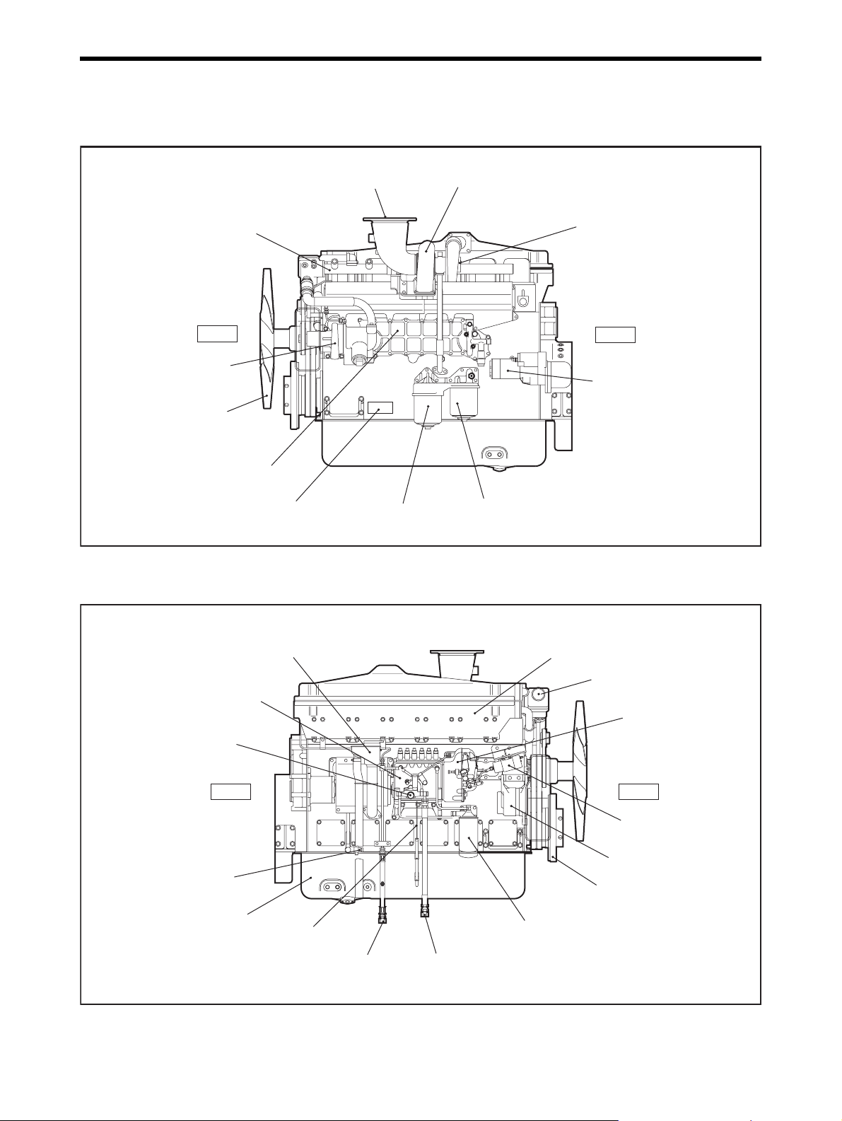
Engine external diagrams
Left view
Water outlet pipe
Water pump
Right view
Front
Fan
Oil cooler
Name plate
Exhaust outlet
Bypass oil filter
Fig. 2-1 Engine left view
Turbocharger
Air intake inlet
Rear
Starter
Oil filter
Breather, oil filler
Fuel injection pump
Fuel feed pump
Rear Front
Coolant drain cock
Oil pan
Oil level gauge
Fuel return port
Air cooler
Thermostat
Governor
Stop solenoid
Alternator
Damper
Fuel filter
Fuel inlet
Fig. 2-2 Engine right view
2-1
Page 24
Chapter 2 NAME OF PARTS
Equipment and instrument
The installed equipment and shapes differ on the engine type.
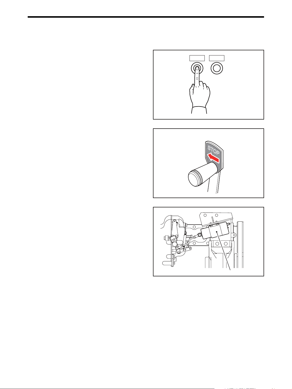
Start and stop instrument
Start switch
When the start switch on the operation panel is
pressed, starting system is operated and cranks the
engine.
Stop switch
When the stop switch on the operation panel is
pressed, the stop solenoid operates and moves the
control shaft of the fuel injection pump to the no-injection position to shut down the engine operation.
Manual stop lever
Use the manual stop lever to shut down the engine in
the event of an emergency. If the stop switch fails to
stop engine operation, use the manual stop lever.
When the manual stop lever, which is located in the
fuel control link, is moved in the [STOP] direction, the
engine stops.
If the engine continues to operate even after the manual stop lever is moved in the STOP position, cut off
the fuel supply to stop the engine.
Stop solenoid
The stop solenoid operates for normal shutdown of
engine operation. The stop solenoid moves the rack of
fuel injection pump to cut the fuel, and consequently
stops the engine. Two types of stop solenoids are
available.
RUN OFF type
Not energized while the engine is running. Energized
by a stop signal to stop the engine.
RUN ON type
Energized while the engine is running, and de-energized to stop the engine.
STOPSTART
(Example)
Fig. 2-3 Start switch and stop switch
STOP
Fig. 2-4 Manual stop lever
Stop solenoid
Fig. 2-5 Stop solenoid
2-2
Page 25
Instruments
This section describes about devices which transmit
signals to necessary instruments of the engine in
operation. Read carefully and understand functions of
each device.
Oil pressure unit
Always detect the oil pressure.
Thermo unit
Always detect the coolant temperature of engine.
Chapter 2 NAME OF PARTS
Oil pressure unit
Fig. 2-6 Oil pressure unit
Thermo unit
Revolution detection pickup
It is installed in the timing gear case, and always
detect engine speed.
Fig. 2-7 Thermo unit
Fig. 2-8 Revolution detection pickup
2-3
Page 26
Chapter 2 NAME OF PARTS
Engine protection devices
The engine protection devices activate an alarm when
an abnormality occurs in the engine in order to protect
the engine and prevent serious problems and accidents. When a protection device is activated, stop the
engine, examine the cause of the abnormality, and
take corrective measures. If the cause of the problem
is unknown, contact a Mitsubishi dealer. Protection
devices installed on the engine and their types (setting
values) and shapes vary depending on the engine
specifications.
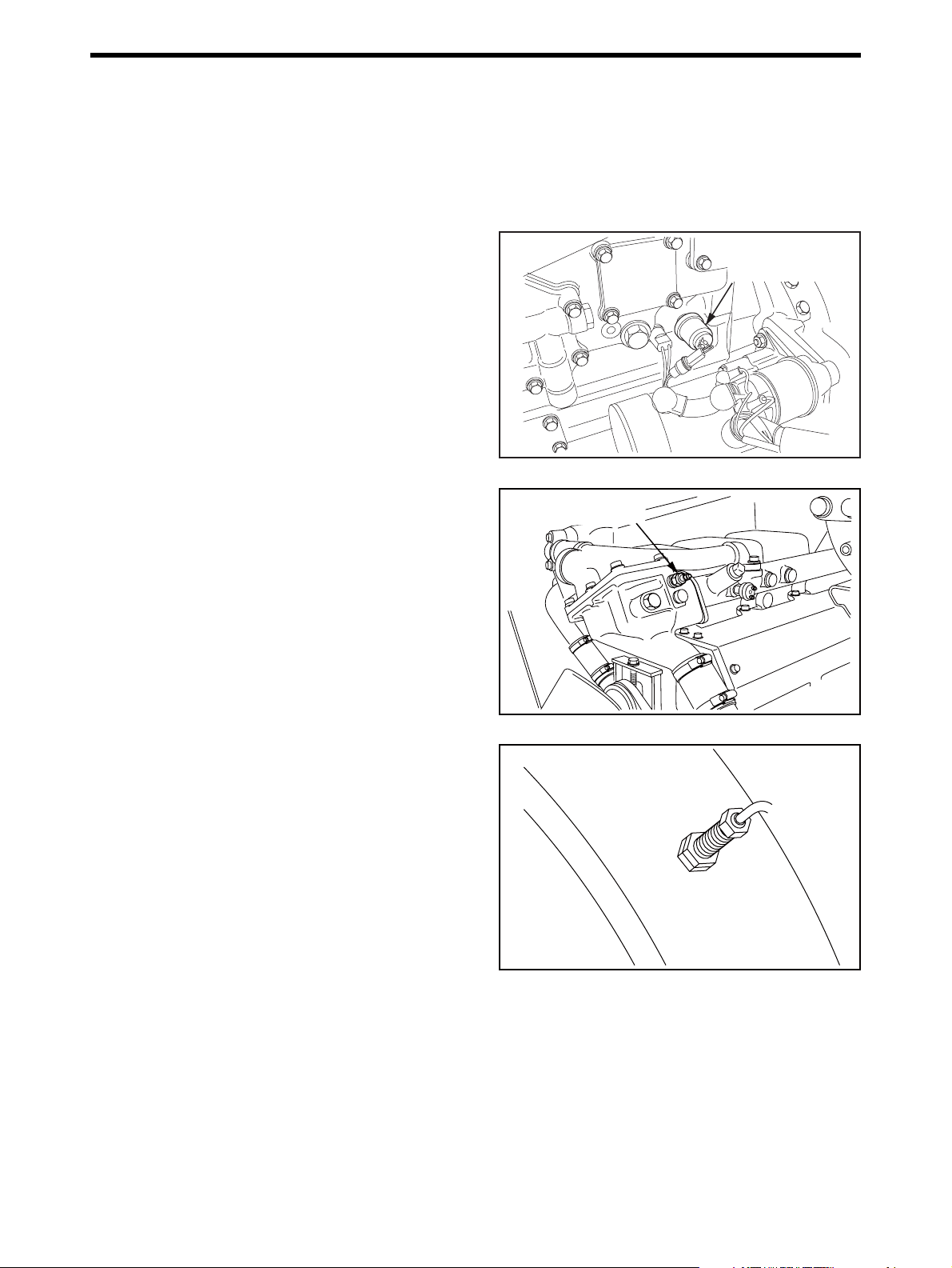
Oil pressure switch
The oil pressure switch generates an alarm when the
engine oil pressure becomes low and reaches the
specified pressure.
Oil pressure switch
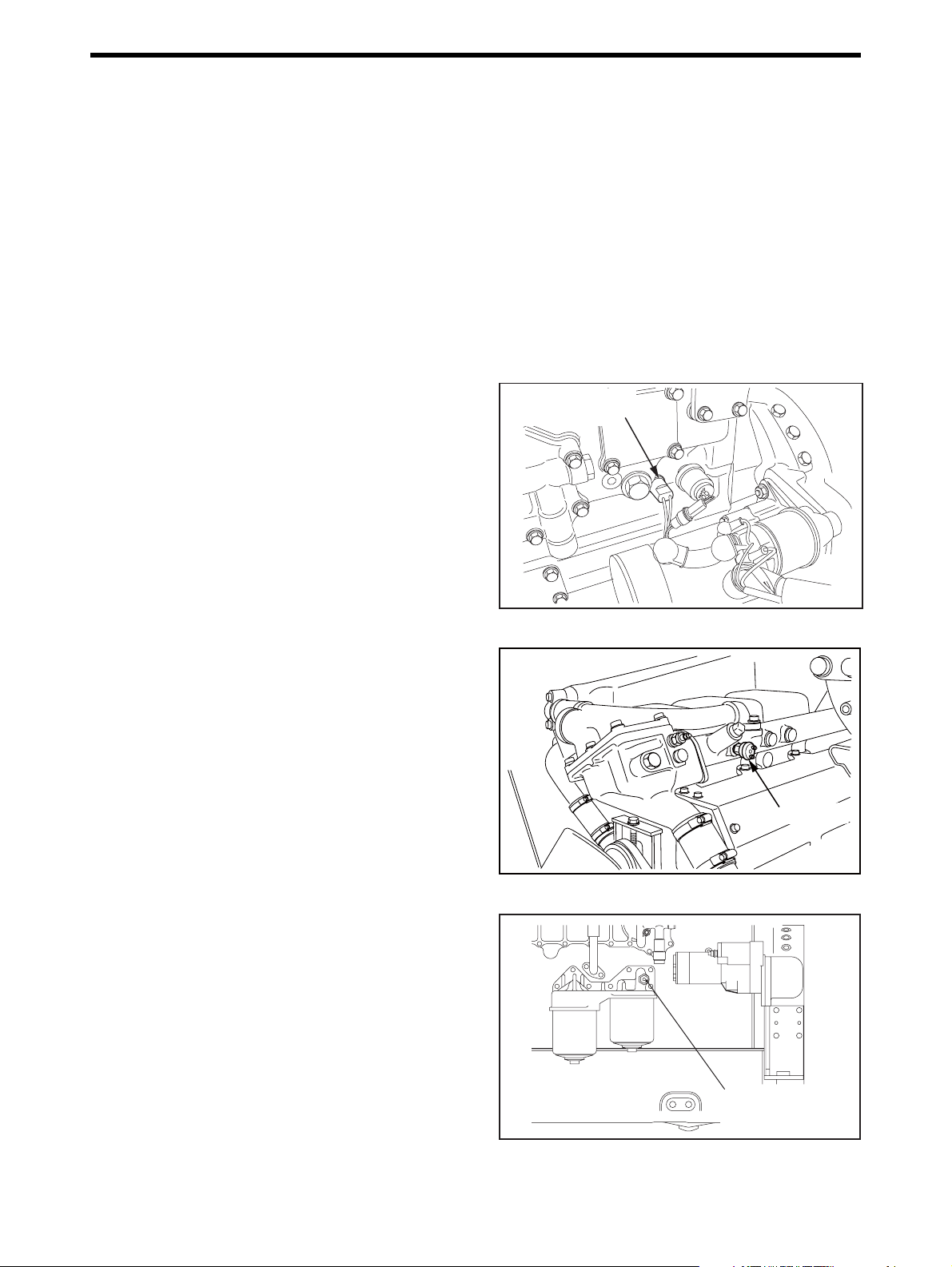
Thermo switch
The thermo switch activates the alarm system when
the coolant temperature reaches the specified value.
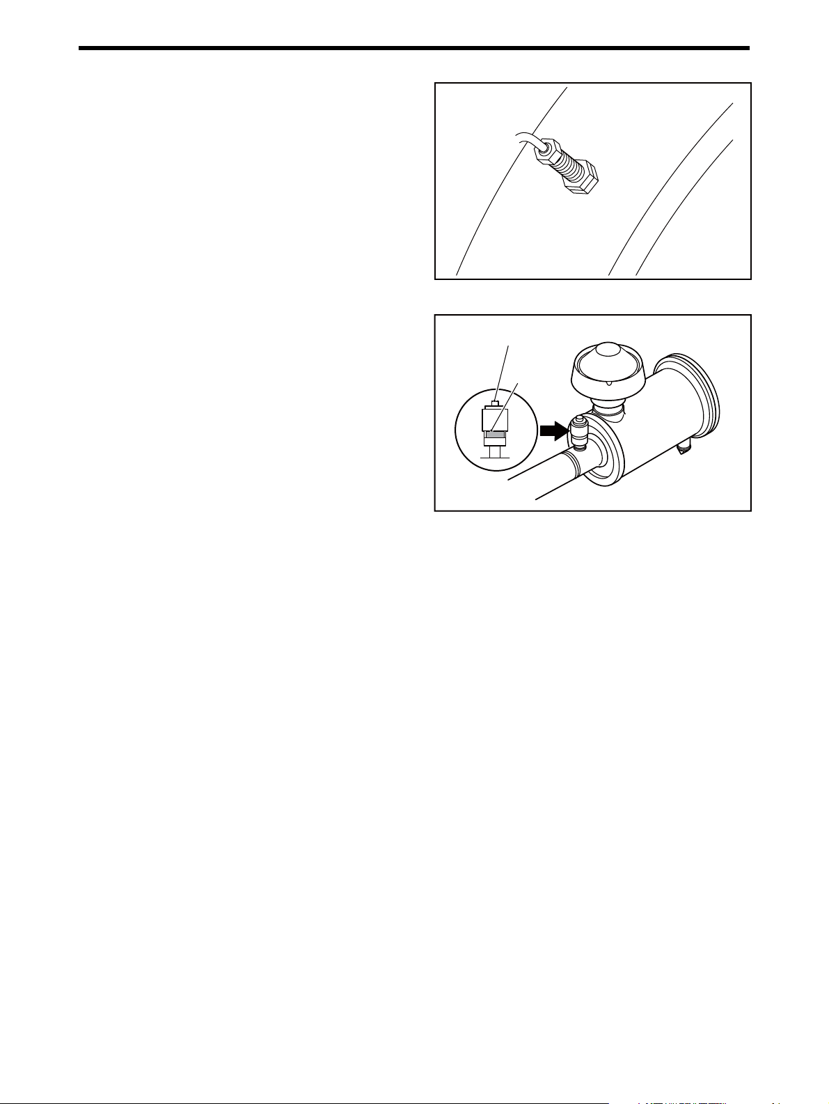
Oil filter alarm switch
The oil filter alarm switch generates an alarm when oil
filters become clogged, the difference in pressure
between inlet and outlet of oil reaches the specified
value.
Fig. 2-9 Oil pressure switch
Thermo switch
Fig. 2-10 Thermo switch
2-4
Oil filter
alarm switch
Fig. 2-11 Oil filter alarm switch
Page 27
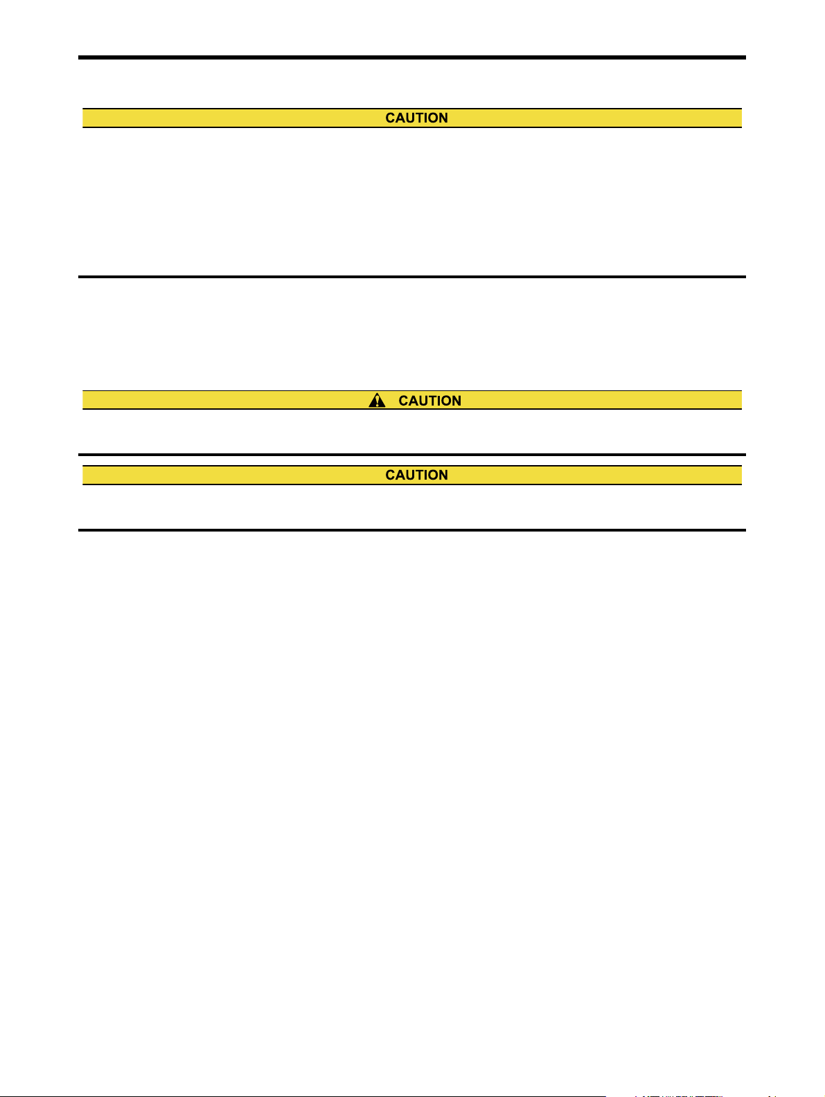
Overrun detection pickup
The overrun detection pickup generates an alarm
when the engine speed becomes high and reaches
the specified engine speed.
Air cleaner indicator
The air cleaner indicator alarms with its red signal
when air cleaner elements become clogged, the difference in pressure between inlet and outlet of air
cleaner reaches the specified value. The signal indicates only, and does not generate an alarm. Therefore, the periodic visually inspection is needed.
Press the reset button on the top of air cleaner indicator and restore the signal after cleaned the air cleaner
indicator or replaced with a new one.
Chapter 2 NAME OF PARTS
Fig. 2-12 Overrun detection pickup
Reset button
Signal
(red)
Fig. 2-13 Air cleaner indicator
2-5
Page 28

Page 29
Chapter 3 OPERATION
Operational environment
Check that the following contents are performed before the engine is operated. Failure to do so may cause various
problems and will shorten the service life of the engine.
Prevent from spreading water (especially, seawater or rainwater) and entering foreign substances to the air inlet
opening.
Prevent from entering foreign substances to the rotating parts.
Prevent from attaching water and dust to the electrical system.
Use the engine at 5 to 40 °C [41 to 104 °F].
Preparation for operating new or overhauled engine
Before proceeding with operation of a new or overhauled engine, conduct the inspections described in this section.
For second operation onward, follow the instructions described in the "Normal engine operation" (3-8).
Preparation of fuel system
When handling fuel, make sure there are no open flames or other fire hazards near the engine.
Wipe off any spilled fuel completely. Spilled fuel can ignite and cause a fire.
Do not remove the strainer when filling the fuel tank.
For fuel to be used, refer to "FUEL" (4-1).
1. Make sure the insides of the fuel tank and fuel supply pipes to the engine are thoroughly clean.
2. Fill fuel tank with fuel.
3. Remove the fuel feed pipe and drain plug from the fuel inlet of engine, and check the discharged fuel for foreign
particles such as dust.
4. Reinstall the drain plug and the fuel feed pipe.
5. Refill fuel tank until fuel level gauge indicates "FULL".
3-1
Page 30
Chapter 3 OPERATION
Fuel system - Bleed air
When fuel overflow from the air vent plug, wipe thoroughly. Spilled fuel causes fire hazard.
After bleeding, lock the priming pump cap securely . If
the cap is not locked tightly, the priming pump can be
damaged, causing a fuel leak that could lead to a
fire.
While feeding fuel with priming pump, bleed air from
the location closest to the fuel tank that is the water
separator, fuel filter, then the fuel injection pump.
Lock the priming pump cap according to "Priming
pump cap tightening method".
[Unlock] [Prime]
Turn counterclockwise
Fig. 3-1 Priming pump - Handle
Move cap up
and down
[Lock]
Turn clockwise
while pressing
Fuel filter - Bleed air
If air vent plugs, the thread portion of the bracket, or
sealing washers are damaged, replace them with
new ones.
1. Loosen the air vent plug on the fuel filter about 1.5
turns.
2. Move the priming pump cap up and down, then
feed fuel.
3. When the fuel from the air vent plug becomes free
from air bubbles, stop priming and tighten the air
vent plug to the specified torque.
Fuel injection pump - Bleed air
1. Loosen the air vent plug on the fuel injection pump
by rotating about 1.5 turns.
2. Move the priming pump cap up and down until the
fuel flow from the air vent plug is free from air bubbles. Push and turn the priming pump cap clockwise to lock in the original position when the fuel
flows are free from bubbles.
3. Tighten the air vent plug on the fuel injection pump.
Air vent plug
Tightening torque
8.8 ± 1 N·m
{0.9 ± 0.1 kgf·m}
[6.4 ± 0.7 lbf·ft]
Fig. 3-2 Fuel filter - Bleed air
Air vent
plug
Priming pump
3-2
Fig. 3-3 Fuel injection pump - Bleed air
Page 31

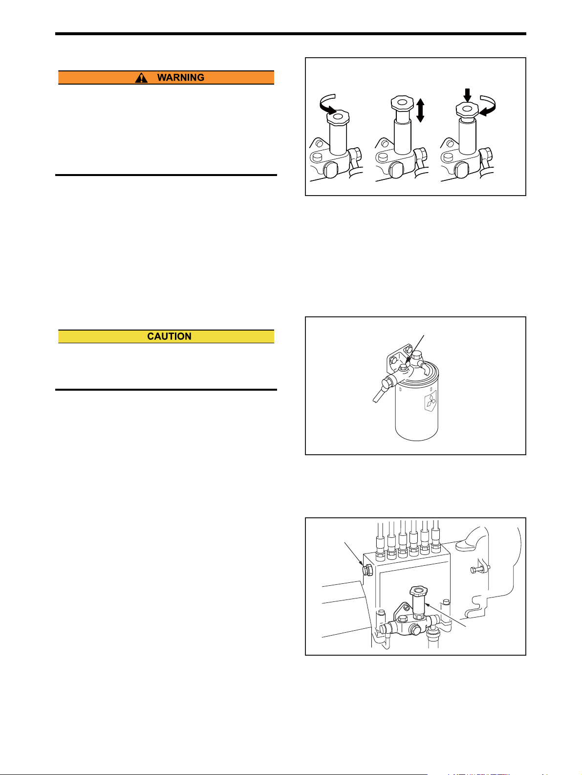
Priming pump cap tightening method
Never fail to tighten the priming pump cap to the
specified angle. If the priming pump cap is not firmly
tightened, internal thread will be worn due to engine
vibration, resulting in sudden ejection of the cap to
cause fuel flow-out. Or if the priming pump cap is
excessively tightened, the head of the priming pump
can be damaged.
Position where
hand-tightening
becomes suddenly
heavy
90 ± 10°
Chapter 3 OPERATION
Priming pump
Head section can be
damaged when
overtightened
(ǰ=120
°
or more)
1. Tighten the priming pump cap firmly by hand, and
place a mark on the priming pump cap.
2. Use a wrench or another appropriate tool to tighten
the priming pump cap 90° ± 10°.
3. Check the mounting position of head packing.
Note: If the head packing has abnormality such as de-
formation or scratches, consult your Mitsubishi
dealer, as the priming pump needs to be
changed.
Fig. 3-4 Priming pump cap tightening method
Head packing
Fig. 3-5 Priming pump head packing
3-3
Page 32

Chapter 3 OPERATION
Preparation of lubrication system
Engine oil - Refill
1. Remove the cap from the oil filler.
2. Fill the engine oil pan with specified engine oil to
the specified level.
Note: For engine oil, refer to "ENGINE OIL" (5-1). For
engine oil capacity, refer to "MAIN SPECIFICA-
TIONS" (12-1).
3. Remove the rocker cover, and pour engine oil to
the valve mechanism and camshaft oil bath. Pour
engine oil to camshaft oil bath from cylinder head
side.
Oil capacity per cylinder: 0.8 L [0.21 U.S. gal.]
4. Reinstall the rocker covers.
5. Check the oil level in the oil pan as follows:
6. Pull out the oil level gauge and wipe it clean with a
waste cloth.
7. Insert the oil level gauge fully into the oil level
gauge guide, then pull out the gauge again.
8. The correct oil level is between the MAXIMUM and
MINIMUM marks on the oil level gauge.
If the oil level is low, add engine oil of the specified
type.
9. Check the oil pan and other area for oil leaks. Re-
pair the oil leakage if any.
10. Crank the engine with the starter for 10 seconds to
circulate oil throughout the engine. After 1 minute
of rest period, perform the above cranking operation again to circulate oil in the engine.
Oil filler
Oil level gauge
Fig. 3-6 Oil filler and oil level gauge
Camshaft oil bath
Fig. 3-7 Pouring engine oil on valve mechanisms and
chamber
To crank the engine, shut off the fuel supply to the
engine and operate the starters.
When conducting the above cranking operation, also
check the items to be inspected for the cooling system by cranking.
11. Check the oil level with the oil level gauge again,
and add oil to the specified level.
3-4
Page 33

Preparation of cooling system
Coolant - Refill
1. Make sure the drain cocks on the engine are
closed firmly.
2. Remove the radiator cap, and pour in undiluted
LLC.
Note: Determine the quantities of LLC based on the
coolant capacity and the LLC concentration
chart.
For the coolant, refer to "COOLANT" (6-1). For
the coolant capacity, refer to ""MAIN SPECIFI-
CATIONS" (12-1).
3. Pour in water (soft water with minimal impurities,
such as tap water) slowly to the full level.
Note: For absolute air bleeding, loosen the air vent
cock on the upper section of thermostat when
adding water.
4. Check the radiator and other parts for coolant
leaks. Repair leakage if found.
5. When coolant reaches the full level, close the radi-
ator cap securely.
6. Crank the engine for about 10 seconds using a
starters.
7. Wait for about 1 minute, then repeat the above
cranking operation to remove air from the water
pump.
Chapter 3 OPERATION
Coolant drain
cock
Fig. 3-8 Coolant drain cock (engine)
Fig. 3-9 Radiator coolant level
To crank the engine, shut off the fuel supply to the
engine and operate the starters.
When conducting the above cranking operation, also
check the items to be inspected for the lubricating
system by cranking.
8. Check the coolant level in the radiator.
9. If the engine is equipped with a reserve tank, fill the
reserve tank with coolant to the full level as well.
Note: Always use the coolant with the same LLC con-
centration.
Fig. 3-10 Reserve tank coolant level
3-5
Page 34

Chapter 3 OPERATION
Preparation of electrical system
Battery - Inspect
If battery electrolyte is spilled on your skin, flush immediately with plenty of water. If battery electrolyte enters the
eyes, flush them immediately with lots of fresh water and seek medical attention at once.
Do not use open flames or other fire hazards near the battery. When handling the battery , be careful of sparks generated by accidental shorting.
Battery electrolyte level - Inspect
Battery electrolyte evaporates during use and the fluid
level gradually decreases. The correct fluid surface
level is between the LOWER LEVEL and UPPER
LEVEL lines.
For the battery without level lines, the correct fluid surface level is about 10 to 15 mm [0.394 to 0.591 in.]
above the top of the plates.
If the fluid level is low, remove the caps and add distilled water to the proper level.
Note: When adding distilled water, pour in carefully.
Specific gravity of battery electrolyte Check
If the specific gravity measured at 20°C [68°F] is lower
than 1.22, then charge the electrolyte.
Table 3-1 Specific gravity of electrolyte
Fig. 3-11 Battery electrolyte level - Inspect
FLOAT
10 to 15 mm
[0.394 to 0.591 in.]
UPPER LEVEL
LOWER LEVEL
ELECTROLYTE
SURFACE
Proper
level
Specific gravity at
20°C [68°F]
Condition Remedy
From 1.26 to 1.28 Fully charged From 1.22 to 1.26 Charged Charge
Less than 1.22 Discharged Charge
ELECTROLYT E
GLASS TUBE
Fig. 3-12 Specific gravity of battery electrolyte - Check
3-6
Page 35

Chapter 3 OPERATION
Test operation
To conduct a test operation, follow the procedures below.
Note: For engine operation, refer to "Normal engine operation" (3-8).
Starting and stopping
1. Start the engine.
2. Operate the engine at low idling speed under no load for 5 to 10 minutes for a warm-up operation.
3. Stop the engine.
Inspection
1. Leave the engine be stopped for about 30 minutes.
2. During this period, check the engine and surrounding area for leaks of fuel, engine oil or coolant.
3. At 30 minutes after the engine stop, check the oil level with the oil level gauge.
4. If the oil level is low, add engine oil from the oil filler. Be sure to use the engine oil of the same brand and type.
5. Open the radiator cap and check the coolant level.
Remove the radiator cap only after the engine has cooled to room temperature. Place a waste cloth over the cap,
and loosen the cap about a half-turn or stand the lever to the upright position to release internal pressure. Opening
the radiator cap while the engine is hot causes steam and hot coolant to spray out and may result in skin burns.
6. If the coolant level is low, add coolant to the specified level.
If the engine is equipped with a reserve tank, fill the reserve tank with coolant to the full level as well.
Always use the coolant with the same LLC concentration.
3-7
Page 36

Chapter 3 OPERATION
Normal engine operation
This section of the manual covers the procedures for the engine operation in normal condition.
Should an engine abnormality be observed during operation, stop the engine and correct the problem, or contact a
Mitsubishi dealer.
Preparations for operation
Always conduct the following inspection before starting the engine.
Engine external - Inspect
Be sure to keep combustible materials away from the engine, especially from the hot engine parts such as exhaust
manifolds, or the battery. Check for fuel and oil leaks. Clean the top surface of the battery. A fire can be caused by
combustible materials placed near hot engine parts. If any abnormality is found, be sure to repair it or contact your
Mitsubishi dealer.
Inspect the engine exterior as described below.
1. Make sure there is no combustible material near
the engine or battery. Also, check to make sure that
the engine and battery are clean. If combustible
materials or dust are found near the engine or battery, remove them.
2. Check the entire engine for leaks of fuel, engine oil
or coolant. If leaks are found, repair the leak, or
contact your local Mitsubishi dealer.
3. Visually check for loose bolts and nuts.
4. Check the electrical wiring including the starters
and alternator.
5. Make sure the following valves, plugs and cocks
are open or closed properly:
Fuel feed valve: Open
Coolant drain cock (plug): Closed
Oil drain valve: Closed
Air supply valve (air tank): Open
Fig. 3-13 Valves for open/closed position - Check
3-8
Page 37

Fuel tank oil level - Check
When working around fuel, make sure there are no open flames, heaters or other fire hazards.
Wipe off any spilled fuel completely. Spilled fuel can ignite and cause a fire.
Do not remove the strainer when filling the fuel tank.
For fuel to be used, refer to "FUEL" (4-1).
Make sure the fuel tank is full.
If the fuel level is low, refill the tank to the "FULL" level.
Engine oil level - Check
1. Pull out the oil level gauge and wipe it clean using
a waste cloth.
2. Insert the oil level gauge fully into the oil level
gauge guide, then pull out the gauge again.
3. The correct oil level is between the MAXIMUM and
MINIMUM marks on the oil level gauge.
4. If the oil level is low, remove the oil filler cap and
add engine oil of the specified type to the MAXIMUM level.
5. Install the oil filler cap after refilling.
6. Check the oil pan and other area for oil leaks.
Oil filler
Fig. 3-14 Oil filler and oil level gauge
Chapter 3 OPERATION
Oil level gauge
3-9
Page 38

Chapter 3 OPERATION
Coolant level - Check
Remove the radiator cap only after the engine has
cooled to room temperature. Place a waste cloth
over the cap, and loosen the cap about a half-turn or
stand the lever to the upright position to release internal pressure. Opening the radiator cap while the
engine is hot causes steam and hot coolant to spray
out and may result in skin burns.
1. Open the radiator cap and check the coolant level.
2. If the coolant level is low, add coolant to the speci-
fied level.
Always use the coolant with the same LLC concentration.
Note: Determine the quantities of LLC based on the
coolant capacity and the LLC concentration
chart.
For the coolant, refer to "COOLANT" (6-1). For
the coolant capacity, refer to ""MAIN SPECIFI-
CATIONS" (12-1).
3. If a reserve tank is equipped, fill the reserve tank
with coolant up to the [FULL] line level.
Turn the cap about
half a turn
Fig. 3-15 Radiator cap
Fig. 3-16 Radiator coolant level
Stand the lever to
the upright position
Fuel control link - Check
Check fuel control link for smooth movement.
When the manual stop lever is pulled to the direction
of arrow, check that the lever can be pulled 2 mm
[0.08 in.] more from the stop position.
Also check ball joint for looseness and play.
3-10
Fig. 3-17 Reserve tank coolant level
Manual stop lever
STOP
Fig. 3-18 Fuel control link - Check
Page 39

Air tank - Drain water
There are 2 places for draining water in the air tank:
drain valve on the top of air tank, and drain handle
on the bottom of drain separator.
1. Open the drain valve slowly, and check that water
in the tank is drained from drain pipe.
2. After water is drained and the air is discharged in
the tank, tighten the drain valve firmly.
3. Loosen the drain handle on the bottom of drain
separator. Check that water in the drain separator
is discharged from the drain pipe.
4. Close the drain handle after draining water firmly.
Air tank air pressure - Check
Check the air pressure gauge to see if the air pressure
in the air tank conforms to the standard.
1. Open the air pressure gauge valve.
2. Check air pressure in the air tank with air pressure
gauge.
2
Specified value: 2.94 MPa {30 kgf/cm
3. Close the air pressure gauge valve.
} [427 psi]
Drain valve
Drain
pipe
Air pressure
gauge
valve
Chapter 3 OPERATION
Drain
separator
Drain
handle
Fig. 3-19 Air tank - Drain water
Air pressure
gauge
Air cleaner - Check
1. Check the air cleaner indicator for the element
clog.
2. If the element is clogged, the red signal mark is vis-
ible.
3. Immediately clean or replace the air cleaner ele-
ment when the signal turns red.
4. After checking, press the bottom on top of the indi-
cator to re-set the alarm signal.
Note: For cleaning of the air cleaner element, refer to
"Air cleaner element - Clean, Check and Replace" (8-17).
Fig. 3-20 Air tank air pressure - Check
Reset button
Signal
(red)
Fig. 3-21 Air cleaner - Check
3-11
Page 40

Chapter 3 OPERATION
Temperature of damper - Check
Damper temperature management by thermo label
It is recommended to use the thermo label for temperature management of the damper in regular use
engine. Check the thermo label before starting engine.
1. Check the thermal part of thermo label is black.
2. Note the highest temperature of thermal part. Note
the temperature periodically, and check the abnormality of temperature alteration.
75ºC [167ºF]<Damper temperature
<80ºC [176ºF]
Thermo label
5E-100!
100 105 110 115 120
5E-75!
75 80 85 90 95
5E-50!
50 55 60 65 70
If the abnormality of temperature alteration is found,
consult a Mitsubishi dealer.
Note: For damper inspection, refer to "Damper - In-
spect" (8-3).
Fig. 3-22 Thermo label of damper
3-12
Page 41

Chapter 3 OPERATION
Starting
The starting method changes based on the application and specifications. Start the engine according to the specified procedure.
Before starting the engine, check to make sure no one is near the engine and that tools are not left on or near the
engine. In a loud voice, notify people in the area when starting the engine.
Do not apply a load to the engine at starting. (Disengage the clutch if installed.)
Continuous operation of the starter will drain the battery power and cause the starter to seize. Do not use the
starter for more than 10 seconds at a time. When the engine does not start, wait for more than one minute before
cranking again.
W arming-up operation
Do not approach rotating parts during operation. Entanglement by rotating parts can cause serious injury.
Do not conduct warm-up operation for a prolonged period of time. Prolonged warm-up operation causes carbon
buildup in the cylinders that leads to incomplete combustion.
Do not turn the battery switch to OFF. Turning off the battery switch while the engine is in warm-up operation not
only stops the instrument operations but also may deteriorate the alternator diode and regulator.
Never turn the key to the START position during operation. The starter may be damaged.
During warming-up operation, do not operate the engine in an overloaded condition (if overloaded, black smoke is
exhausted). Overloading causes not only high fuel consumption but also excessive carbon deposits inside the
engine. Carbon deposits cause various problems and will shorten the service life of the engine.
After the engine starts, operate the engine in a no load condition at low idling speed for 5 to 10 minutes to warm up
the engine.
Checking engine oil pressure
During warming-up operation, check if the oil pressure
is in the range of standard value.
Also, make sure the oil pressure gauge is operating
properly.
Note: The oil pressure gauge may indicate a higher
level than normal level immediately after the engine starts, due to the low oil temperature. The
pressure gradually lowers to the normal level as
the oil temperature rises.
External inspection during warm-up
Visually check the external view of the engine for
leaks of fuel, engine oil and coolant, or leaks of
exhaust gas from joints.
3-13
Page 42

Chapter 3 OPERATION
Operation
Cautions when operating
Do not approach rotating parts during operation.
Entanglement by rotating parts can cause serious
injury.
Do not touch any hot part of the engine such as
exhaust pipes during operation or immediately after
shut down. A hot engine can cause burns.
Always provide adequate ventilation in the engine
room. If air supply to the engine room is not sufficient,
the room temperature rises and can affect engine
output and performance.
For the first 50 hours, operate the engine under a
light load for break-in operation. Operating the engine
under heavy load or severe conditions during the
break-in period can shorten the service life of the
engine.
Do not turn the battery switch to OFF when the
engine is in operation. Turning off the battery switch
during operation not only stops the instrument operations but also may deteriorate the alternator diode
and regulator.
Never turn the key to the START position during
operation. The starter may be damaged.
Inspection during operation
Carefully check the exterior of engine such as piping
joints for leaks.
Check for abnormal engine noises or vibrations such
as knocking.
Check the color of exhaust gas from the exhaust muffler.
Check the instruments and gauges for proper operation and make sure they indicates normal values.
Table 3-2 Standard values at rated speed
Item Reference value
Engine oil pressure
Coolant temperature 70 to 90°C [158 to 194°F]
Oil Temperature
(oil pan)
Exhaust temperature 550 °C [1022 °F] or lower
Intake air pressure
Note: (a) When the oil pressure drops below 0.29 MPa
2
{3 kgf/cm
below 0.10 MPa {1 kgf/cm
idling, stop the engine immediately. Be sure
to locate the cause of problem and correct it
before restarting the engine.
(b) When the high temperature alarm switch is
activated in normal operation, change the engine operation immediately to low idling operation until the engine temperature decreases
to the normal operating level. Then, operate
the engine for another 5 or 6 minutes for cooling before stopping the engine. Be sure to locate the cause of problem and correct it
before restarting the engine.
} [42.7 psi] in normal operation, or
0.39 MPa {4 kgf/cm
[57 psi] or more
110°C [230 °F] or lower
0.15 to 2.5 MPa
{1.5 to 2.5 kgf/cm
[21 to 36 psi]
2
} [14.2 psi] at low
2
}
2
}
3-14
Page 43

Chapter 3 OPERATION
Stopping
Stopping the engine abruptly while engine part s are hot due to high-speed operation can be a cause for heat up of
the engine parts and shorten the service life of the engine. Before stopping the engine, let it idle at low speed for 5
to 6 minutes to cool down, and check the engine for abnormalities.
Never accelerate the engine immediately before shutting it down.
Do not restart the engine immediately after abnormal shut down. When the engine stops with alarms, be sure to
locate the cause of the problem and correct the problem before restarting the engine. After restarting the operation, check the engine for abnormalities again. If abnormalities still exist, contact your Mitsubishi dealer.
Engine stopping method changes depending on the specifications.
Follow the instructions according to the specifications of the equipment.
Emergency stop
When stopping the engine by pulling the manual
stop lever, continue pulling the lever until the engine
stops completely. If not, the engine may start again.
STOP
To perform the emergency stop, pull the manual stop
lever to the arrow direction. Continue pulling the lever
until the engine stops completely.
Note: When the engine does not stop even if the man-
ual stop lever is pulled, stop fuel supply.
Fig. 3-23 Manual stop lever
Inspection after stopping
Inspect the engine for leaks of fuel, oil or coolant. If any leak is found, repair the leak or contact your Mitsubishi
dealer.
3-15
Page 44

Page 45

Recommended fuel
Chapter 4 FUEL
Use the recommended fuel specified in this manual.
Do not refill the fuel tank more than the specified
level, as it may result in a fire.
Use a diesel fuel that meets "ASTM diesel fuel oil
No.2-D" (JIS K2204 diesel fuel).
It is necessary to use fuel that has a pour point suitable for the ambient temperature. Choose the fuel
type from the following chart.
Table 4-1 Recommended fuel
Specification Classification
JIS K2204, 2205 TYPE 1, TYPE 2, TYPE 3
ASTM D975 No.1-D, No.2-D
BS 2869 CLASS A1, CLASS A2
DIN 51601 DIESEL-FUEL
ISO 8217 DMX-CLASS
Diesel fuel
In
Compliance
with
JIS K2204
Fig. 4-1 Recommended fuel
[-21] [-4] [14] [32] [50] [68] [86] [104]
Special No. 3
No. 3
No. 2
Diesel fuel
Fig. 4-2 Recommended fuel according to ambient
temperature
No. 1
Special No. 1
Handling fuel
When using fuel stored in a storage tank, leave it to sit for more than 24 hours so that dust and water can settle at
the bottom. Then, use the upper clean fuel.
Fill up the fuel tank or service tank after each operation.
This prevents water from mixing with fuel in the tank and also gives time for dust and water to sep arate and settle at
the bottom of the tank.
Before refilling, clean the areas around the caps thoroughly and remove the caps from the drum and tank. Also
clean your hands and the hose before refueling. When using a hand-operated pump, be careful not to pump water
or sediment accumulated at the bottom of the storage tank.
Be sure to use a strainer when filling fuel tank. For a complete filtration, it is recommended to use a clean lint-free
cloth together with the strainer.
4-1
Page 46

Chapter 4 FUEL
Table 4-2 Recommended and limit values of fuel property
Properties Recommend value Limit value Properties
Flash point As stipulated by regulation As stipulated by regulation
JIS K 2204, 2205
Diesel fuel: 50 °C [122°F]
or higher
Initial boiling
Distillation
point
90 % distillate
temperature
Pour point
170°C [338°F] or above 170°C [338°F] or above
330 to 380°C [626 to 716°F] 330 to 380°C [626 to 716°F]
6°C [42.8°F] minimum
below ambient temperature
6°C [42.8°F] minimum
below ambient temperature
Cloud point Below ambient temperature Below ambient temperature
Carbon residue
(10 % bottom oil)
0.4 weight % or lower 1.0 weight % or lower JIS K 2270
Cetane number 45 or higher 45 or higher
Cetane index
(new type)
Kinematic viscosity
45 or higher 45 or higher JIS K 2280-1996
2
2.0 mm
8.0 mm
10.5 mm
16.0 mm
/s or higher
at 30°C [86°F]
2
/s or lower
at 50°C [122°F]
2
/s or lower
at 40°C [104°F]
2
/s or lower
at 30°C [86°F]
2.0 mm
10.5 mm
16.0 mm
2
/s or higher
at 30°C [86°F]
2
8.0 mm
/s or lower
at 50°C [122°F]
2
/s or lower
at 40°C [104°F]
2
/s or lower
at 30°C [86°F]
Sulfur content 0.2 weight % or lower 1.0 weight % or lower
JIS K 2254
JIS K 2269
JIS K 2541
0.05 weight percent
(same as diesel fuel)
is recommended.
Water content
and sediment
0.1 volume % or lower 0.1 volume % or lower JIS K 2275
Ash content 0.03 weight % or lower 0.03 weight % or lower JIS K 2272
Copper plate corrosion
(100°C [212°F], 3 hrs.)
No.3 or lower No.3 or lower
Density at 15°C [59°F] 0.83 to 0.87 g/cm
75 % carbonization or less
at 250°C [482°F]
Caulking
55 % evaporation or less
at 230°C [446°F]
Tar-free at 180°C [356°F]
Aromatics substances
(by HPLC)
38 volume % or lower 38 volume % or lower
3
0.80 to 0.87 g/cm
3
Should not be carbonized
100% at 250 °C [482 °F]
ASTM - No.3
JIS K 2513 - Discoloration
No.3
Fed791B (U.S.A.)
250°C [482°F]×24Hr
230°C [446°F]×24Hr
180°C [356°F]×48Hr
JIS K 2536
Total of aromatic content
Asphaltene 0.1 weight % or lower 0.1 weight % or lower
JIS B 9931
Foreign substances 5.0 mg/l or lower 5.0 mg/l or lower
Including foreign
substances in the fuel
pipe lines
4-2
Page 47

Chapter 5 ENGINE OIL
Recommended engine oil
Use only the engine oils recommended in this manual. Never use other oils.
The use of inappropriate or inferior oils will result in sticking of piston rings, seizure between piston and cylinder, or
premature wear of bearings and moving parts, and significantly shortens the service life of the engine.
Many oil standards, which are established through
special engine tests, are available to determine the
quality of oil depending on the engines to which they
will be applied and on operating conditions. Among
those standards, SAE viscosity grades and API
(American Petroleum Institute) service classifications
are mostly used to classify engine oils.
SAE specifies the viscosity only, while the API service
classification indicates the quality level of engine oil.
For engine lubrication oil, please use API service classification CF.
Fig. 5-1 Recommended engine oil
OIL
Class CF
API Service
Classification
Handling engine oil
Before filling the engine with engine oil, stop the engine and make sure there are no open flames and other fire
hazards near the engine. Leaked or spilled oil on hot surfaces or electrical components can cause a fire. Wipe off
any spilled oil immediately and thoroughly. After filling, securely close the filler cap.
Never mix different brands of engine oil. Mixing different brands of engine oil may cause a chemical reaction of
additives in the engine oil that could degrade the engine oil quality.
When handling oil in greater than the legally specified quantities, be sure to have the work performed by a service
station in compliance with the law. When removing oil from the engine or oil can, use an oil pump. Do not suck oil
with the mouth to siphon it.
Be sure to close the cap on the oil can after use.
Keep oil in a well-ventilated place and out of direct sunlight.
Be sure to obtain the MSDS of the engine oil used and follow the instructions of the MSDS.
5-1
Page 48

Chapter 5 ENGINE OIL
Properties of engine oil and its influence on engine performance
Engine oil lubricates the engine and greatly influences
the performance and durability of the engine.
Distinctive differences of engine oil from other oils are
that engine oil lubricates hot sections adjacent to the
combustion chamber and is strongly affected by the
combustion products. Engine oils, therefore, are
required to have cooling, sealing, deterging, and neutralizing abilities in addition to the lubricating function.
Because diesel engines especially produce acid products such as sulfuric acid due to the sulfur content of
the fuel and soot due to imperfect combustion that
contaminates oils, engine oils for diesel engines must
have capabilities not only to withstand severe lubricating conditions, but also to neutralize acid products to
prevent them from agglomerating and depositing.
The function of performance required for engine oils is
shown below:
Good detergent dispersibility for high temperature
applications, for preventing contamination and deposition of sludge and soot.
Excellent acid neutralizing capability to inhibit oxidiza-
tion due to sulfur content of fuel.
Good oxidation stability that withstands long hours at
high temperature.
Appropriate viscosity to maintain lubricity and low
temperature startability.
Good rust and corrosion resistance to water.
Good foam resistance to prevent the lubricating qual-
ity from lowering due to oxidation.
Main properties of engine
persibility of engine oil is to disperse sludge and soot
in oil in order to prevent it from depositing.
Viscosity
Oils flow with difficulty at lower temperatures, and flow
smoothly at high temperatures. The oil viscosity is a
property that indicates resistance to flow. This property of viscosity directly relates to low temperature
startability, lubricity, fuel consumption by friction loss,
and oil consumption.
For identification of an oil's viscosity, SAE (Society of
Automotive Engineers) numbers are widely used. The
property of engine oils is identified not only by viscosity number that shows thickness and thinness of viscosity at particular temperature, but also by viscosity
index that shows the changes in oil viscosity with
changes in temperature.
The viscosity of engine oil identified by the number of
SAE shows the thickness or thinness of viscosity at
particular temperature.
When the viscosity index of oil is high, it means the
change of viscosity due to temperature is small.
The viscosity index (VI)-100 of oil is generally applied
to diesel engine oil. Oils indicated by, for instance, VI100 are called single grade oil, which fall under one
range of viscosity. There are also oils called "multigrade oil" for which viscosity falls under two ranges of
viscosity and they are indicated by, for instance, SAE
15W-40, which means that at a lower temperature, the
oil has 15W grade, and at a higher temperature it has
a 40W grade. ("W" indicates the suitability of oil for
colder temperature). In other words, SAE15W-40 indicated on oil demonstrates SAW15 grade of viscosity
at a lower temperature and 40 grade viscosity at a
higher temperature.
oil
Detergent dispersibility
Engine oil performance degrades through oxidation
and also by external causes. Acid products such as
sulfuric acid due to sulfur content of fuel become insoluble sludge. Incomplete combustion of fuel creates
soot in oil.
This sludge and soot in oil are accumulated in the
groove or on the inner surface of piston rings and will
result in seizure or wear of the piston rings, or it will
lower heat transfer of the piston rings drastically. Dis-
5-2
Page 49

Selection of oil viscosity
Use the following chart to select the appropriate oil
viscosity according to the ambient temperature.
Excessively high oil viscosity causes power loss and
an abnormal rise of oil temperature, while excessively
low oil viscosity accelerates wear due to inadequate
lubrication, and also causes a decrease in engine output due to leakage of combustion gas.
Temperature
°C [°F]
Engine oil
viscosity
Chapter 5 ENGINE OIL
-30 -20 -10 10 20 30 40 500
SAE10W
SAE30
SAE40
SAE15W-40
Fig. 5-2 Selection of oil viscosity
[122][50] [68] [86] [104][-21] [-4] [14] [32]
5-3
Page 50

Chapter 5 ENGINE OIL
Definition of properties of engine oil
Viscosity
Viscosity is a basic physical property of engine oil and
is considered as the most important aspect when evaluating oil.
Contamination of oil by blow-by gas and deterioration
of oil by its natural aging increase the viscosity and
degrade the performance of viscosity , which will cause
the deposition of sludge inside the engine and oil filter
clogging. Contamination of oil by fuel and sheared
molecules of viscosity index improver in oil decrease
the viscosity and degrade the performance of viscosity, which will cause insufficient lubrication and friction/
wear of engine parts.
Total base number
Total base number (TBN) shows the ability to neutralize acids such as organic acid due to engine oil oxidation, or sulfurous or sulfuric acid due to the sulfur
content of fuel.
Because TBN indicates the amount of dispersant
detergent in oil, it can be used to estimate consumption of basic dispersant detergent. The ability to disperse sludge declines as dispersant detergent is used
up.
To tal acid number
The total acid number in oil increases as the organic
acid is being derived by the engine oil oxidation, or
sulfurous acid or sulfuric acid derived by the combustion of sulfur content of fuel, or the oil becomes contaminated with imperfect combustion products.
An increase in the total acid number will result in corrosion or wear of the inner parts of the engine (such
as cylinder liners or metal) due to sulfur content, and
piston ring seizure due to sludge.
Water content
Water in oil promotes corrosion/wear, and decreases
lubricity in sliding parts.
Flash point
The flash point is lowered by contamination with fuels.
Flash point is measured to check the dilution of fuel.
The dilution of fuel reduces oil film, and causes insufficient lubrication that will cause friction or wear of
engine parts.
Insoluble
Insoluble includes acid products of engine oil, imperfect combustion products, sludge or soot, metal abrasive particles and dust. Insoluble is an indication of
degradation/contamination of oil.
Dispersant detergent, which is an additive in engine
oil, absorbs sludge particles, and disperses them as
fine particles in oil. Total insoluble density and remaining dispersibility can be obtained by measuring insoluble and coagulated insoluble (using chemical
specialities to stop action of disperse detergent and to
collect the sludge dispersed in oil) by which piston ring
seizure or premature wear can be prevented before it
occurs.
5-4
Page 51

Chapter 5 ENGINE OIL
Service limits of engine oil
Engine oil degrades through the use and by lapse of time.
To determine the timing of engine oil replacement, analyze the used oil, and understand the condition of oil deterioration and oil defacement. It is also required to compare the oil analysis results and the engine analysis results
including inside contamination and wear condition of engine, and to consider the engine operating condition.
Refer to the following table for the determination of engine oil performance degradation. If any of the following deviate the limit, replace the engine oil with new oil.
Table 5-1 Engine oil properties
Properties Standard value Test method
2
mm
Viscosity
Total base number mgKOH/g
Total acid number mgKOH/g Up to +3.0 of new oil JIS K 2501
Water content Vol % Maximum 0.2 JIS K 2275
/s@100°C
[212°F]
2.0 or more with hydrochloric acid (HCL)
1/2 of new oil or more with perchloric
+30% or less
-15% or more
acid (PCA) method
of new oil JIS K 2283
method
JIS K 2501
Flash point (open cup) °C [°F] Over 180 [356] JIS K 2265
Pentane insoluble Wt % Maximum 0.5 Comply with ASTM D893
Pentane insoluble coag-
ulated
Wt % Maximum 3.0 Comply with ASTM D893
Engine oil analysis service
For a long term service life of engine, Mitsubishi Heavy Industries, Ltd. offers an engine oil analysis service.
The service includes special oil sampling tools, the sample oil analysis and result data.
The engine oil analysis service provides the followings:
The quantity of fine metal powder in engine oil due to abrasion, by which worn parts can be located.
Water, LLC or salt that should not be in engine oil can be detected.
Engine oil deteriorating conditions, by which appropriate engine oil renewal intervals, operating conditions, proper
inspection and maintenance schedule can be planned.
The engine oil analysis service can diagnose the internal condition of the engine, which is necessary when disassembling the engine. It is highly recommended to take advantage of our engine oil analysis service so that you can
learn the engine condition before any malfunction occurs to the engine.
5-5
Page 52

Chapter 5 ENGINE OIL
How to order engine oil sampling tool set
The oil sampling pump is reusable, but oil sampling bottle and suction pipe must be replaced each time.
For replacing tools, order them through the regular part supply system. The analysis fee is included in the price of
the sampling bottle.
Therefore, if you sample the oil in other bottles, you will not receive our analysis service.
Also, note that optional analysis requires additional charge.
Table 5-2 Engine oil sampling tool set
Product
name
Engine oil
sampling set
Engine oil
sampling kit
Parts No. Remarks
36291-19100
36291-00098
Contains oil sampling pump, pipes
and bottles
1 Carton:6 bottles
Includes suction
pipes and oil sample
bottle
Oil sampling pump
Oil sampling bottle
Fig. 5-3 Engine oil sampling tool set
5-6
Page 53

Chapter 6 COOLANT
Note: In this operation manual, the word "coolant" represents the liquid combined water and LLC.
Recommended water for coolant
Use soft water for the engine cooling system. The water quality must meet the requirements in the Table below.
Basically, the water quality should be within the recommended value, however, up to the limit is acceptable.
Table 6-1 Water quality standards
Item
PH (25 °C [77 °F]) - - 6.5 to 8.0 6.5 to 8.5 ○○
Electrical conductivity
(25°C [77°F])
Total hardness CaCO
M alkalinity CaCO
Chlorine ion Cl
Sulfuric acid ion SO
Total iron Fe ppm < 1.0 < 1.0 - ○
Silica SiO
Residue from evapo-
ration
Note: Figures in parentheses are the standard value. In addition to the items specified above, turbidity is specified to
be below 15 mg/liter.
Chemical
symbol
- mS/m < 25 < 40 ○○
3 ppm < 95 < 100 - ○
3 ppm < 70 < 150 - ○
-
2-
4
2 ppm < 30 < 50 - ○
-
Unit
ppm < 100 < 100 ○ -
ppm < 50 < 100 ○ -
ppm < 250 < 400 - ○
Recommend
value
Limit value
Main adverse effect
Corrosion
and rust
Scale forma-
tion
Long life coolant (LLC)
Should coolant or LLC be accidentally swallowed, induce vomiting immediately and seek medical attention. If LLC
should enter eyes, flush immediately with plenty of water and seek medical attention.
Be sure to use Mitsubishi genuine long life coolant (LLC) "GLASSY long life coolant (Ethylene glycol type)" or "PG
GLASSY long life coolant (Non-amine type)" as coolant. When using other brand LLCs by necessity, be sure to use
the LLC that meets the Mitsubishi specification. Mitsubishi heavy industries, Ltd. disclaim the warranty claim concerning malfunctions caused by the use of LLC that does not meet the following specification.
Genuine LLC
Mitsubishi Heavy Industries, Ltd. recommends the use
of our genuine long life coolant "GLASSY long life
coolant (Ethylene glycol type)", and Eco-friendly product "PG GLASSY long life coolant (Non-amine type)",
which are most appropriate coolant for Mitsubishi diesel engine.
Fig. 6-1 GLASSY - LLC
6-1
Page 54

Chapter 6 COOLANT
Other brand LLCs
Never mix genuine Mitsubishi LLC with other brand
LLCs. Mixing with other brand LLCs degrades the
performance of the genuine Mitsubishi LLC.
When using LLC other than Mitsubishi genuine long
life coolant (LLC) "GLASSY long life coolant (Ethylene
glycol type)" or "PG GLASSY long life coolant (Nonamine type)", be sure to use the LLC which meets Mitsubishi specification.
The quality and performance of commercially available LLCs as well as their component variations are
the responsibility of LLC suppliers.
Before purchasing commercial LLC, be sure to discuss the suitability of LLC with the LLC supplier.
Use only all-season LLC (non-amine type). Do not use
antifreeze alone instead of LLC.
Standard for other brand LLC
When using other brand LLCs by necessity , be sure to
use the LLC that meets following specification. Mitsubishi heavy industries, Ltd. disclaim the warranty
claim concerning malfunctions caused by the use of
LLC that does not meet the following specification.
General demands of LLC
LLC shall be a homogeneous liquid.
Engine cooling system shall not receive troubles
such as corrosions and precipitation products etc. by
LLC when the LLC is diluted to 30 to 60% density.
LLC shall be mixed with other LLC that satisfies this
specification, and shall not separate elements each
other, and shall not decrease the performance each
other.
LLC shall not allow the container to be corroded, and
shall not has precipitation products etc. even if LLC is
left in the container for six months.
LLC shall not has extraction products etc. even if LLC
is kept in -20 to -25°C [-4 to -13°F]
The validity term of the quality that provides with this
specification is 2 years after it delivers with the indoor
normal temperature keeping.
6-2
Page 55

Chapter 6 COOLANT
LLC specification
LLC shall examine according to JIS K2234 section 7 (examination methods), and satisfy this specification. General
matters and the sample to the examination is shown in JIS K2234.
Table 6-2 LLC specification
Property Standard value
External Not precipitation
3
Density Minimum 1.112 g/cm
(Stock solution)
Water content Maximum 5.0 wt % (Stock solution)
(20/20 °C) [68/68 °F]
Frozen temperature
30 vol % Maximum -14.5 °C [6 °F]
50 vol % Maximum -34.0 °C [-29 °F]
Boiling temperature Minimum 155 °C [311 °F] (Stock solution)
pH 7.0 to 11.0 (30 vol %)
Bubbling character
(ASTM D3306-01)
30 vol % Maximum 4.0 ml
1/3 vol % Maximum 150 ml, Disappearance of bubble
33
within 5 sec.
Hard water adaptability Maximum 1.0 (50 vol %)
2
2
2
2
2
2
Metallic causticity
(88 ± 2°C [190 ±
3.6°F],
336 ± 2 Hr,
30 vol % (E.G),
50 vol % (P.G))
Aluminum ±0.30 mg/cm
Cast iron ±0.15 mg/cm
Mass
change
Test Piece
Steel ±0.15 mg/cm
Brass ±0.15 mg/cm
Solder ±0.30 mg/cm
Copper ±0.15 mg/cm
External of test piece after the exam-
ination
Not corrosion on surface excluding between
test piece and spacer. Discoloration is OK.
Bubbling while examination Not bubbling overflow
pH 6.5 to 11.0
Properties
of liquid
after the
examination
pH change ± 1.0
Precipitation Maximum 0.5 vol %
External of liquid
Not remarkable discoloration, separation
and gel.
Circulation metallic causticity
(98 ± 2°C [208 ±
3.6°F],
1000 Hr,
30 vol % (E.G),
50 vol % (P.G))
Test Piece
Properties
of liquid
after the
examination
Mass
change
External of test piece after the exam-
ination
Aluminum, Cast iron, Steel,
Brass, Solder, Copper
±0.30 mg/cm
2
Not corrosion on surface excluding between
test piece and spacer. Discoloration is OK.
pH 7.0 to 9.0
pH change ± 1.0
Pre-alkalinity change ± 15%
Precipitation Maximum 1.0 vol %
External of liquid
Density
Fe, Cu, Al, Zn, Pb, NH
of ion
Not remarkable discoloration, separation
and gel.
+
4
Maximum 10 ppm
6-3
Page 56

Chapter 6 COOLANT
Circulation metallic causticity
(88 ± 3°C [190 ±
5.4°F],
1000 ± 2 Hr,
30 vol % (E.G))
Test Piece
Properties
of liquid
after the
examination
Table 6-2 LLC specification
Property Standard value
Aluminum ±0.60 mg/cm
Cast iron ±0.30 mg/cm
Mass
change
Steel ±0.30 mg/cm
Brass ±0.30 mg/cm
Solder ±0.60 mg/cm
Copper ±0.30 mg/cm
External of test piece after the examination
Not corrosion on surface excluding between
test piece and spacer. Discoloration is OK.
2
2
2
2
2
2
pH 6.5 to 11.0
pH change Maximum ±1.0
External of liquid Not remarkable discoloration, separation
and gel.
Condition
of parts
Pump seal Not trouble while the examination
Inside of pump case and blade Not remarkable corrosion
Tensile strength change -60 to 0%
Elongation change -40 to +20%
Silicon
Volume change 0 to +40%
Hardness change -20 to +10%
Rubber adaptability
(30 vol %,
115 °C [239 °F],
360 Hr)
Acrylonitrile butadiene
rubber
Tensile strength change 0 to +10%
Elongation change -15 to +15%
Volume change 0 to +40%
Hardness change -10 to 0%
Tensile strength change 0 to +10%
Ethylene
propylene
diene
monomer
Elongation change -30 to 0%
Volume change 0 to +10%
Hardness change -10 to 0%
Storage stability vol % (30 vol %, room temperature, 6 Hr) Maximum 0.3
6-4
Page 57

Chapter 6 COOLANT
Maintenance of LLC
Should coolant or LLC be accidentally swallowed, induce vomiting immediately and seek medical attention. If LLC
should enter eyes, flush immediately with plenty of water and seek medical attention.
LLC is toxic. Never dispose of coolant containing LLC drained from engine into regular sewage. For disposal of
used coolant, consult LLC distributor.
Replacement intervals of LLC
Be sure to renew LLC (coolant) at the intervals specified in the maintenance schedule of this manual.
Failure to renew LLC may cause malfunctions due to deterioration of anti-corrosive performance and cavitation.
The coolant containing LLC recommended in this manual should be renewed every 8000 hours or 2 years, whichever comes first, for a regular-use or general-purpose engine.
LLC concentration
When determining the LLC concentration, provide a margin of 5 °C [41 °F] below the expected lowest temperature
in your region.
LLC of less than 30% concentration does not provide sufficient corrosion protection. If the LLC concentration is
lower than 10%, it may accelerate corrosion.
When adding coolant, do not add plain water. Always use coolant with the same LLC concentration.
Table 6-3 Recommended LLC concentration
Lowest ambient temperature (°C [°F])
Item Type External
LLC concentration
(%)
Note: (a) When ambient temperature is -30°C [-22°F] or below, use Mitsubishi genuine LLC "GLASSY long life cool-
ant (Ethylene glycol type)".
(b) The concentration above is based on Mitsubishi genuine LLC "GLASSY long life coolant (Ethylene glycol
type)" or "PG GLASSY long life coolant (Non-amine type)".
For determining the accurate LLC concentration, refer to the instructions for the LLC used.
GLASSY Green 30 40 50 60
PG GLASSY Red 40 55 70 -
-10°C [14°F]
or above
-20°C [-4°F]
or above
-30°C [-22°F]
or above
-45°C [-49°F]
or above
6-5
Page 58

Chapter 6 COOLANT
Importance of LLC
Today's trend is toward smaller and lighter engines
offering greater output, lower fuel consumption and
lower exhaust emission levels.
Conditions to which engine coolant is subjected,
therefore, are becoming severer due to longer operating hours, higher coolant temperature and higher coolant circulating speed.
Many different materials such as steel, aluminum,
copper, solder and rubber are used in the cooling system, and they are also subjected to the severe conditions described above. Those materials have different
ionization characteristics, and this difference accelerates corrosion through the medium of engine coolant.
To prevent such a problem, the use of LLC (long life
coolant) that contains anti-corrosive additive is very
important.
Characteristics of LLC additive and important notes
LLC contains several chemicals in such proportions
as to produce chemical reactions that suppress corrosion (ionization) of engine parts in contact with the
coolant. LLC loses its effectiveness by hours of use as
well as lapse of time.
Moreover, if the chemicals are not maintaine d, certain
chemicals in the LLC become rapidly used up and
result in dissolution of metals instead of protecting
metals from corrosion. Consequently, other corrosion
preventing chemicals react with dissolving metals and
accelerate corrosion. This condition generates more
severe corrosion than when plain soft water is used.
This is a typical problem caused by the use of inappropriate LLC.
Examples of abnormalities caused by LLC
Pitting of iron parts
Amines are generally effective in suppressing the rusting of ferrous metals, but they are said to cause problems for copper parts.
Dissolved copper (copper corrosion) in the cooling
system deposits on iron parts and the copper deposits
cause corrosion and then pitting on iron parts that
have a high ionization characteristics due to galvanic
or local-cell action.
Corrosion of aluminum parts
Silicate is highly effective in protecting aluminum
against rusting. However, it is unstable in a solution in
which the pH is 9 or lower, and can turn to gel a nd precipitate in the solution. For this reason, the pH is usually specified to be about 10 to ensure a high alkaline
level.
This means, after silicate is used up, the high alkalinity
causes chemical attacks on aluminum. To prevent this
problem, proper maintenance of the coolant is
required. For case example, rapid wear of mechanical
seals in the water pump due to secondary effects of
silicate gel formed. Corrosion of aluminum parts after
silicate is consumed.
Pitting and clogging of the radiator
When LLC deteriorates or when its concentration in
the coolant is too low, the anti-corrosion performance
of LLC lowers and results in the corrosion of metals.
Brass and solder tend to corrode faster than other
metals, and corrosion of these metals is said to cause
water leakage and clogs. Example: Holes and clogs in
radiator
6-6
Page 59

Chapter 7 MAINTENANCE SCHEDULE
How to use the maintenance schedule
Periodic inspection not only extends the service life of the engine but also serves to ensure safe operation. Be sure
to conduct inspections and maintenance according to the maintenance schedule.
The maintenance schedule shows the standard service intervals. If you notice any abnormalities such as abnormal
noise, black exhaust smoke, white exhaust smoke, extremely high temperature of exhaust gas, abnormal vibration,
and fuel, oil or exhaust gas leakage, make sure to conduct the inspection and maintenance work, regardless of recommended service intervals in the "Maintenance schedule."
Note: Appropriate service intervals vary depending on the usage and operating conditions as well as consumption
of fuel, oil and coolant. Check the operating record of the engine to determine the most appropriate service
intervals. (Feel free to consult your Mitsubishi dealer regarding service intervals.)
Service the items at multiples of the original requirement. For example, at 1000 service hours, also service those
items listed under every 250 service hours and every 50 service hours.
Items marked with * in the maintenance schedule require special tools or large equipment. For the servicing of
those items, contact your Mitsubishi dealer.
Periodic Maintenance Chart
Appropriate service intervals vary depending on the engine specifications. Perform all daily inspection and maintenance items in an accordance with the following 3 categories.
Periodic maintenance chart for regular use engine
When the engine is used as a regular use engine, perform the periodic inspection and maintenance in accordance
with the "Periodic Maintenance Chart for Engine in Regular Use".
Periodic maintenance chart for emergency engine
When the engine is used as an emergency engine, perform the periodic inspection and maintenance in accordance
with the "Periodic Maintenance Chart for Emergency Engine". Due to the nature of application, an emergency
engine is subject to demanding operating conditions such as a quick startup and immediate supply of power. In
addition, it must operate reliably in the event of an emergency. Therefore, be sure to perform the daily inspection
and also conduct the following operation for maintenance purposes. Once every week: Operate the engine under
no load (for 3 to 5 minutes). (When operating the engine for the adjustment of peripheral devices, limit the operating
time to 10 minutes.) Once every month: Operate the engine under load (for 15 to 30 minutes with more than 1/2
load). If the engine cannot be operated under load every month, operate the engine under load (more than 1/2 load)
for more than 2 hours once every year. During the engine maintenance operation, check the ease of startup, oil
pressure, and exhaust color and vibration.
Periodic maintenance chart for general purpose engine
If the engine is used for different purposes other than the above usage, do maintenance according to the "Periodic
Maintenance Chart for General-Purpose Power Supply Engine".
7-1
Page 60

Chapter 7 MAINTENANCE SCHEDULE
General Definition of Regular-Use Engine, Emergency Engine and General-Purpose Engine
General definition of regular-use engine
An engine operated with a constant base load for the purpose of generating electric power, which is used independently or in combination with commercial power supply. An engine operated under a fluctuating load throughout a
day for supplying rated electric power in lieu of commercial power.
General definition of emergency engine
An engine used for emergency power generation such as main power supply and commercial power supply.
General definition of general-purpose engine
An engine used for a purpose other than power generation - for example, to drive a pump, as the main engine for a
ship, and for an industrial vehicle - and operated under constant or cyclically varying load and speed.
7-2
Page 61

Chapter 7 MAINTENANCE SCHEDULE
Periodic maintenance chart for regular use engine
Table 7-1 Periodic maintenance chart for regular use engine
Interval and Service item Page
Every 50 service hours or
every month
First 50 service hours for
a new or overhauled
engine
Every 250 service hours
First 250 service hours
for a new or overhauled
engine
Every 1000 service hours
Fuel tank - Drain water 8-5
Water separator - Drain water 8-7
Bolts and nuts on the engine - Retighten *
Engine oil, Oil filter and Bypass oil filter - Replace
It is recommended to check the engine oil characteristics at the same time.
The oil filters must be replaced when the filter alarm lights.
Engine oil, Oil filter and Bypass oil filter - Replace
It is recommended to check the engine oil characteristics at the same time.
The oil filters must be replaced when the filter alarm lights.
Valve clearance - Inspect and Adjust
(Check valve mechanism at the same time.)
Fuel filter - Replace 8-8
Water separator - Inspect and Replace 8-7
Gauze filter - Clean 8-7
V-belt and belt tension - Inspect and Adjust 8-2
Fuel tank - Drain water (Replace parts as necessary) 8-5
Valve clearance - Inspect and Adjust
(Check valve mechanism at the same time.)
Fuel injection timing - Inspect and Adjust *
8-10
8-10
*
*
Every 2000 service hours
Every 4000 service hours
Fuel injection nozzle - Nozzle tip replacement (Check the spray condition
and adjust the fuel injection pressure after replacement)
Checking Movement of the Rack (during operation) of the fuel injection
pump (including the governor)
Fuel pipe - Inspect 8-9
Oil pipe - Inspect 8-12
Top end of the engine - Overhaul
Remove the cylinder head, and inspect and service the combustion chambers.
Turbocharger - Inspect 8-15
Damper - Inspect 8-3
Starter - Inspect 8-19
Protection devices operation - Inspect *
Unit seal and Oil seal of water pump - Replace *
Checking LLC concentration level in the coolant *
*
*
*
7-3
Page 62

Chapter 7 MAINTENANCE SCHEDULE
Table 7-1 Periodic maintenance chart for regular use engine
Engine - Major overhaul
Disassemble engine, clean, check and change major parts.
[Parts to be changed]
Inlet and exhaust valves, inlet and exhaust valve seats, valve rotators, valve
cotters, rocker arm adjusting screws, valve push rods, bridge caps, camshaft
bushings, camshaft expansion plugs, main bearings, cylinder liners, main
bearing cap bolts and washers, piston rings, connecting rod bearings,
damper, crankcase thrust plate and consumable items (gasket s, oil seals, Orings, etc.)
[In second overhaul, replace the following parts in addition to the parts listed
above]
Cylinder head bolts, valve guides, valve bridge guides, valve bridges, valve
Every 8000 service hours
springs, tappets, camshaft thrust plates, pistons, piston pins, connecting rod
bolts, connecting rod bushings, rocker bushings, fuel pipe assembly, oil pipe
assembly
Fuel injection pump - Inspect and Test (Replace parts as necessary) *
Governor - Inspect and Test (Replace parts as necessary) *
Protective Devices - Repair or Replace
High coolant temperature, low oil pressure, overspeeding, starting failure,
water supply failure, undervoltage, overvoltage, overcurrent, low coolant
level in tank, low fuel level in tank, low air pressure in tank, etc.
Interval and Service item Page
*
*
Auxiliary devices operation - Check
Water heater, oil heater, oil priming pump, fuel transfer pump, governor
motor, etc.
Every 8000 service hours
or every 2 years
As required
Items marked with * in the maintenance schedule require special tools or large equipment. For the servicing of
those items, contact your Mitsubishi dealer.
Coolant - Change 8-13
Fuel system - Bleed air 3-2
Radiator fins - Check and Clean 8-14
Pre-cleaner - Clean, Inspect and Replace 8-16
Air cleaner element - Clean, Check and Replace 8-17
Cleaning the Inside of the Engine Breathers *
Stop solenoid - Inspect or Replace *
Couplings - Inspect or Replace *
Inspecting the Vibration-isolating Rubber *
*
7-4
Page 63

Chapter 7 MAINTENANCE SCHEDULE
Periodic maintenance chart for emergency engine
Table 7-2 Periodic maintenance chart for emergency engine
Interval and Service item Page
Engine external - Inspect (Check for leakage of fuel, oil and coolant) 3-8
Fuel tank oil level - Check 3-9
Engine oil level - Check 3-9
Coolant level - Check 3-10
Every week
Every month
Every 6 months
Air tank air pressure - Check (air motor type or direct inlet type) 3-11
Water leakage of air cooler - Inspect Operating the engine for maintenance (operate the engine under no load for
5 to 10 minutes)
Check for ease of starting, color of exhaust smoke, abnormal vibration,
abnormal noise, abnormal smell and gauge indication (oil pressure gauge,
coolant temperature gauge, oil temperature gauge, exhaust temperature
gauge, tachometer, etc.)
Engine Oil for Mixing of Fuel and Water - Inspect 8-11
Fuel control link - Check 3-10
Battery electrolyte level - Inspect 3-6
Air tank - Drain water 3-11
Air compressor oil level - Inspect and Refill Conducting Engine Maintenance Operation (Operate the engine with more
than 1/2 load for 15 to 30 minutes)
Check for ease of starting, color of exhaust smoke, abnormal vibration,
abnormal noise, abnormal smell and gauge indication (oil pressure gauge,
coolant temperature gauge, oil temperature gauge, exhaust temperature
gauge, tachometer, etc.)
Check fuel injection pump and governor rack movement
Checking LLC concentration level in the coolant *
Cleaning the Inside of the Coolant Tank -
-
-
Every 1 year
Engine mechanical
Fuel system
V-belt and belt tension - Inspect and Adjust 8-2
Bolts and nuts on the engine - Check and Retighten *
Damper - Inspect 8-3
Valve clearance - Inspect and Adjust
(Check valve mechanism at the same time.)
Inspecting the Vibration-isolating Rubber *
Foundation Bolts - Inspect *
Couplings - Inspect or Replace *
Fuel tank - Drain water 8-5
Water separator - Drain water 8-7
Fuel Injection Nozzle Spray Condition and Spray Pressure - Inspect and Adjust
Fuel injection timing - Inspect and Adjust *
Fuel pipe - Inspect 8-9
*
*
7-5
Page 64

Chapter 7 MAINTENANCE SCHEDULE
Table 7-2 Periodic maintenance chart for emergency engine
Engine
Lubricating system
Interval and Service item Page
Oil pipe - Inspect 8-12
Engine Oil Properties - Analyze *
Engine Oil Pressure (Maintenance operation) - Inspect
and Adjust
Water pump - Inspect *
*
Every 1 year
Cooling system
Air intake system
Electrical system
Air starter system
Electromagnetic Valve and Pressure Reducing Valve of
the Cooling System - Inspect, Disassemble and Clean
Strainer (including with/ball tap) of Cooling Water Inspect, Disassemble and Clean
Coolant Properties (when only soft water is used) Inspect (Change coolant according to the analysis
results)
Air cleaner element - Clean, Check and Replace 8-17
Pre-cleaner - Clean, Inspect and Replace 8-16
Starter - Inspect 8-19
Alternator - Inspect 8-19
Specific gravity of battery electrolyte - Check 3-6
Air Heater - Inspect -
Air strainer - Drain water and Clean 8-20
Air tank - Inspect safety valve operation 8-20
Air starter valve - Inspect *
Electromagnetic Valve and Pressure Reducing Valve -
Inspect and Clean
Air distribution valve - Inspect *
*
*
*
*
Air compressor belt tension - Inspect *
Protection devices operation - Inspect
High coolant temperature, low oil pressure, overspeeding, starting failure,
water supply failure, undervoltage, overvoltage, overcurrent, low coolant
level in tank, low fuel level in tank, low air pressure in tank, etc.
Auxiliary devices operation - Check
Engine control, fuel transfer pump, governor motor, room ventilating fan,
solenoid, storage pump, water tank ball tap, water heater, oil heater, oil priming pump, etc.
*
*
7-6
Page 65

Chapter 7 MAINTENANCE SCHEDULE
Table 7-2 Periodic maintenance chart for emergency engine
Interval and Service item Page
Engine oil, Oil filter and Bypass oil filter - Replace
It is recommended to check the engine oil characteristics at the same time.
The oil filters must be replaced when the filter alarm lights.
Fuel filter - Replace 8-8
Water separator - Inspect and Replace 8-7
Gauze filter - Clean 8-7
8-10
Every 2 years
Every 4 years
Fuel control linkage ball joint - Inspect
(Replace parts as necessary)
Coolant - Change 8-13
Thermostat - Inspect *
Turbocharger - Inspect 8-15
Draining water from the exhaust muffler 8-15
Air compressor overhaul (air motor type or direct inlet type) *
Top end of the engine - Overhaul
Remove the cylinder head, and inspect and service the combustion chambers.(If the abnormalities of first and second cylinders are found, inspect all
cylinders. )
Checking oil cooler for contamination, clogging and leakage *
Checking Oil Pump for Discoloration and Other External Defects *
Governor oil filter - Replace 8-12
Fuel tank - Clean 8-5
Fuel injection pump - Inspect and Test (Replace parts as necessary) *
Governor - Inspect and Test (Replace parts as necessary) *
Radiator fins - Check and Clean 8-14
Rubber hose - Replace *
8-6
*
Pre-cleaner - Clean, Inspect and Replace 8-16
Air cleaner element - Clean, Check and Replace 8-17
Instruments - Repair or Replace
Oil pressure gauge, coolant temperature gauge, oil temperature gauge,
exhaust temperature gauge, tachometer
*
7-7
Page 66

Chapter 7 MAINTENANCE SCHEDULE
Table 7-2 Periodic maintenance chart for emergency engine
Interval and Service item Page
Engine - Major overhaul
Disassemble engine, clean, check and change major parts.
Damper - Replace *
Oil pump - Repair or Replace *
Fuel injection nozzle - Nozzle tip replacement (Check the spray condition
and adjust the fuel injection pressure after replacement)
Rubber parts and O-rings - Replace *
Unit seal and Oil seal of water pump - Replace *
Every 8 years
Items marked with * in the maintenance schedule require special tools or large equipment. For the servicing of
those items, contact your Mitsubishi dealer.
Turbocharger - Disassemble and Inspect *
Air cooler - Disassemble and Clean *
Vibration-isolating rubber - Repair or Replace *
Couplings - Repair or Replace *
Governor motor - Repair or Replace *
Air ventilation fan of the room - Repair or Replace *
Stop solenoid - Inspect or Replace *
Ball tap of water tank - Repair or Replace *
Other consumables - Replace *
*
*
7-8
Page 67

Chapter 7 MAINTENANCE SCHEDULE
Periodic maintenance chart for general purpose engine
Table 7-3 Periodic maintenance chart for general purpose engine
Interval and Service item Page
Fuel control linkage ball joint - Inspect 8-6
Every 50 service hours or
every month
Air strainer - Drain water and Clean (air motor type or direct inlet type) 8-20
Air tank - Drain water (air motor type or direct inlet type) 3-11
First 50 service hours for
a new or overhauled
engine
Every 250 service hours
or every 1 year
First 250 service hours
for a new or overhauled
engine
Every 1000 service hours
or every 2 years
Bolts and nuts on the engine - Retighten *
Engine oil, Oil filter and Bypass oil filter - Replace
It is recommended to check the engine oil characteristics at the same time.
The oil filters must be replaced when the filter alarm lights.
Engine oil, Oil filter and Bypass oil filter - Replace
The oil filters must be replaced when the filter alarm lights.
Governor oil filter - Replace 8-12
V-belt and belt tension - Inspect and Adjust 8-2
Radiator fins - Check and Clean 8-14
Draining water from the exhaust muffler 8-15
Air tank - Inspect safety valve operation (air motor type or direct inlet type) 8-20
Valve clearance - Inspect and Adjust
(Check valve mechanism at the same time.)
Fuel filter - Replace 8-8
Water separator - Inspect and Replace 8-7
Gauze filter - Clean 8-7
Air strainer - Drain water and Clean (air motor type or direct inlet type) 8-20
Zinc Rod - Replace *
8-10
8-10
*
Every 2000 service hours
or every 3 years
Every 4000 service hours
or every 5 years
Bolts and nuts on the engine - Retighten *
Valve clearance - Inspect and Adjust
(Check valve mechanism at the same time.)
Fuel injection timing - Inspect and Adjust *
Fuel pipe - Inspect 8-9
Oil pipe - Inspect 8-12
Fuel injection nozzle - Nozzle tip replacement (Check the spray condition
and adjust the fuel injection pressure after replacement)
Protection devices operation - Inspect (high water temperature, low oil pressure, overspeed)
Top end of the engine - Overhaul
Remove the cylinder head, and inspect and service the combustion chambers.
Fuel control linkage ball joint - Inspect 8-6
Damper - Inspect 8-3
Air cooler - Clean *
Heat exchanger - Wash *
*
*
*
*
7-9
Page 68

Chapter 7 MAINTENANCE SCHEDULE
Table 7-3 Periodic maintenance chart for general purpose engine
Interval and Service item Page
Engine - Major overhaul
Disassemble engine, clean, check and change major parts.
Fuel injection pump - Inspect and Test (Replace parts as necessary) *
8000 hours
Every 8000 service hours
or every 2 years
As required
Items marked with * in the maintenance schedule require special tools or large equipment. For the servicing of
those items, contact your Mitsubishi dealer.
Governor - Inspect and Test (Replace parts as necessary) *
Protective Devices - Repair or Replace *
Auxiliary devices operation - Check *
Coolant - Change 8-13
Fuel system - Bleed air 3-2
Air cleaner element - Clean, Check and Replace 8-17
Pre-cleaner - Clean, Inspect and Replace 8-16
*
7-10
Page 69

Chapter 8 PERIODIC INSPECTION AND MAINTENANCE PROCEDURES
Engine mechanical
Engine external - Inspect
Be sure to keep combustible materials away from the engine, especially from the hot engine parts such as exhaust
manifolds, or the battery. Check for fuel and oil leaks. Clean the top surface of the battery. A fire can be caused by
combustible materials placed near hot engine parts. If any abnormality is found, be sure to repair it or contact your
Mitsubishi dealer.
Inspect the engine exterior as described below.
1. Make sure there is no combustible material near the engine or battery. Also, check to make sure that the engine
and battery are clean. If combustible materials or dust are found near the engine or battery, remove them.
2. Check the electrical wiring for such components as the starter and alternator for looseness.
3. Check the entire engine for leaks of fuel, engine oil or coolant. If leaks are found, repair the leak, or contact your
local Mitsubishi dealer.
4. Make sure the following valves, plugs and cocks are open or closed properly:
Fuel feed valve: Open
Coolant drain cock (plug): Closed
Oil drain valve: Closed
8-1
Page 70

Chapter 8 PERIODIC INSPECTION AND MAINTENANCE PROCEDURES
V-belt and belt tension - Inspect and Adjust
If defects such as cuts or surface separations are found during inspection, replace the belt.
Keep oil and grease away from the belt, since they may cause the belt to slip and shorten the service life.
Excessive belt tension can cause rapid wear of the alternator bearing and shorten the service life of the belt.
Adjust the belt tension accurately by following the procedures below.
V-belt - Inspect
1. Inspect the V-belt visually for separation or damage. If any abnormality is found, replace the belt with a new one.
2. Inspect belt tension (deflection).
Push the belt downward at the midway between pulleys. If the deflection is 10 to 15 mm [0.39 to 0.59 in.], the
tension is correct.
V-belt pushing force: Approx. 98 to 147 N {10 to 15 kgf} [22 to 32.4 lbf]
If the deflection of belt is not within the standard, adjust the belt tension.
V-belt tension (Alternator side) - Adjust
1. Remove the belt cover.
2. Loosen all retaining bolts of the alternator and ad-
justing plate.
3. Operate the alternator to adjust the V-belt tension.
4. Tighten all retaining bolts of the alternator and ad-
justing plate.
5. Reinstall the belt cover.
Fan pulley
Alternator
pulley
Adjusting bolt
Tension pulley
Water pump pulley
Fig. 8-1 V-belt and belt tension - Inspect and Adjust
V-belt tension (Water pump side) - Adjust
1. Loosen the retaining nut of tension pulley.
2. Turn the adjusting bolt to adjust the belt tension.
3. After adjusting, tighten the nut to be retained the tension pulley.
Adjusting plate
8-2
Page 71

Damper - Inspect
Damper - Check visually
Chapter 8 PERIODIC INSPECTION AND MAINTENANCE PROCEDURES
When installing a damper protective cover to the
engine, do not use a cover that encloses the damper .
Installation of a closed cover can cause damper
damage due to heat.
Check the vibration damper for oil leakage, scratches,
deformation, discoloration and peeling of paint. Check
carefully for swelling on the cover (use a scale), oil
leaks from the shim, discoloration and peeling of paint
due to heat.
Note: If defects are found in the damper, contact your
Mitsubishi dealer.
Cover
Fig. 8-2 Damper - Check visually
Damper temperature management
For making damper function well, heat of damper must be dissipated from its surface to prevent excessive damper
heating. Mitsubishi inspects each engine before shipment to ensure proper operating temperature of the vibration
damper. However, the vibration damper temperature varies depending on ambient conditions. Therefore, observe
the following suggestions and provide sufficient ventilation for the vibration damper and equipment.
1. Make sure the temperature of the outside damper surface does not exceed the temperature that described in the
following table when operating the engine with rated power for an hour.
Table 8-1 Damper temperature management
Type of damper Continuous Standby
Viscous damper 90°C [194°F] 100°C [212°F]
Viscous rubber damper 80°C [176°F] 90°C [194°F]
2. When installing a safety cover to damper, check ventilation carefully and make sure the damper temperature remains below the temperature specified above, with the cover in place.
3. It is recommended to use the thermo label for the temperature management of damper in regular use engine.
8-3
Page 72

Chapter 8 PERIODIC INSPECTION AND MAINTENANCE PROCEDURES
Thermo label - handle
The white thermal part of thermo label becomes black when reaching the specified value.
Note: The thermal part that becomes black once does not return to white. Therefore, if the engine stops and then the
temperature of damper drops, the thermo label continues indicating the maximum temperature in operation.
1. Attach a thermo label to the periphery or front end of damper.
2. Note the maximum temperature of the thermal part of thermo label when engine stops. Note the temperature pe-
riodically, and check the abnormality of temperature alteration.
Note: (a) When the temperature of thermo label increased, identify the abnormality of engine or other cause. Then,
reattach new thermo label, and check the change of temperature.
(b) If the temperature indication of thermo label comes close to the limit temperature of damper or the abnor-
mality is found in change of temperature, contact a Mitsubishi dealer.
Table 8-2 Thermo label for temperature management
Parts
name
Thermo
label
100-120
Thermo
label
75-95
Thermo
label
50-70
Parts No.
32522-04211
20 labels set: 32522-04200
32522-04111
20 labels set: 32522-04100
32522-04311
20 labels set: 32522-04300
Temperature
measuring
range
100 to 120°C
[212 to 248°F]
75 to 95°C
[167 to 203°F]
50 to 70°C
[122 to 158°F]
Fig. 8-3 Damper temperature management
Thermo label
5E-100
100 105 110 115 120
5E-75
75 80 85 90 95
5E-50
50 55 60 65 70
8-4
Page 73

Chapter 8 PERIODIC INSPECTION AND MAINTENANCE PROCEDURES
Fuel system
Fuel system - Inspect
When handling fuel, make sure there are no open flames or other fire hazards near the engine.
Wipe off any spilled fuel completely. Spilled fuel can ignite and cause a fire.
Fuel tank - Clean
Do not remove the strainer when filling the fuel.
For fuel to be used, refer to "FUEL" (4-1).
1. Close the fuel feed valve to cut off the fuel supply to the engine.
2. Prepare the fuel receiving can, place it under the drain cock.
3. Drain all fuel in the tank from drain cock on the bottom of fuel tank.
4. Clean the inside of fuel tank.
For more information, refer to the operation manual attached to a fuel tank.
5. Add fuel to the fuel tank.
6. Open the fuel feed valve, and bleed air for the fuel system.
Note: For bleeding fuel system, refer to "Fuel system - Bleed air" (3-2).
Fuel tank - Drain water
If fuel gets mixed with particles of foreign matter such
as dust, dirt, or water, it can cause not only decrease
of output but also malfunctions of the fuel system. To
avoid such a problem, drain fuel tank as described
below.
1. Prepare the oil pan (capacity of 2 L [0.53 U.S. gal.]
or more) under the drain cock of fuel tank.
2. Open the drain cock of fuel tank and drain fuel at
least 1 to 2 L [0.26 to 0.53 U.S. gal.].
3. Make sure that water and particles of foreign matter discharged with fuel. Close the drain cock.
Drain cock
Fig. 8-4 Fuel tank - Drain water
8-5
Page 74

Chapter 8 PERIODIC INSPECTION AND MAINTENANCE PROCEDURES
Fuel control linkage ball joint - Inspect
Check ball joint in the fuel control linkage for play. If
the amount of play is 0.1 mm [0.004 in.] or more,
replace the ball joint with the new one.
0.1 mm
[0.004 in.]
Ball joint
If the sealed ball joints are found loosened, contact
your Mitsubishi dealer. If the seal on the ball joint is
broken, the warranty is invalidated.
If the ball joints are integrated in the control linkage,
replace the control linkage when the ball joints have
loosened. When installing ball joints, be sure to tighten
the nuts firmly.
0.1 mm
[0.004 in.]
Rod
Lever
Fig. 8-5 Fuel control linkage for looseness - Inspect
Ball joint
Control linkage
Fig. 8-6 Fuel control linkage - Remove
8-6
Page 75

Chapter 8 PERIODIC INSPECTION AND MAINTENANCE PROCEDURES
Water separator - Inspect and Replace
Water separator - Drain water
1. Prepare a plate, and place it under the drain cock
of water separator.
2. Open the drain cock, and drain water in the water
separator.
3. Close the all drain cocks after draining.
Outlet cock
Fig. 8-7 Water separator - Drain water
Inlet cock
Drain cock
Water separator element - Replace
Open the inlet valve slowly to prevent overflowing fuel. Wrap a cloth around the water separator before the fuel
may spill.
1. Close the inlet cock and outlet cock.
2. Turn the T -handle, and remove the water separator
cover.
3. Open the drain cock, and drain fuel in the water
separator.
4. Close the all drain cocks after draining.
5. Replace the element with a new one.
6. Fill the water separator with fuel.
7. Attach the water separator cover , and tighten the T -
handle.
8. Open the inlet cock and outlet cock.
Outlet cock
Inlet cock
Drain cock
Fig. 8-8 Water separator element - Replace
Element
Gauze filter - Clean
If the gauze filter is clogged, the fuel supply becomes
insufficient, resulting in decrease in power output or
engine stall.
1. Remove the eye bolt at the inlet port of fuel feed
pump.
2. Using a screw driver, remove the gauze filter that is
fitted inside the eye bolt.
3. Soak the gauze filter in the fuel, and clean it with a
brush.
4. After cleaning, install the gauze filter into the eye
bolt using a screw driver.
5. Install the eye bolt to the fuel feed pump.
6. Bleed the air from the fuel filter.
Note: For bleeding the fuel filter, refer to "Fuel filter -
Bleed air" (3-2).
Gauze filter
Eye bolt
Fuel feed pump
Fig. 8-9 Gauze filter - Clean
8-7
Page 76

Chapter 8 PERIODIC INSPECTION AND MAINTENANCE PROCEDURES
Fuel filter - Replace
1. Clean the area around the fuel filters.
2. Prepare a drip pan, and place it under the fuel fil-
ters.
3. Using a filter wrench, remove the fuel filters.
4. Wipe off fuel on the fuel filter cartridge mounting
surface of the filter bracket with a waste cloth.
5. Check new fuel filters for proper seating of the gasket.
Do not use the filter of which case has dents, as it
may be damaged during operation, and cause fuel
leakage that becomes fire hazard.
6. Apply clean fuel to the gasket on the new fuel filter .
7. Install the fuel filter to the filter bracket. When the
gasket contacts the mounting surface of the filter
bracket, further rotate 3/4 to a full turn.
Air vent plug
Gasket
Fuel filter
Fig. 8-10 Fuel filter - Replace
Apply fuel to
the gasket.
Do not use a filter wrench to install the fuel filter.
Do not dent or scratch the fuel filter surfaces.
8. After installing the new fuel filter, bleed the fuel filter.
Note: For bleeding the fuel filter, refer to "Fuel filter -
Bleed air" (3-2).
9. Start the engine and let it idle for several minutes.
10. Make sure that there is no fuel leak during the en-
gine operation. If fuel leakage is found, loosen the
fuel filter and check the gaskets for damage. If
there is no damage, retighten the fuel filter.
Fig. 8-11 Fuel filter
8-8
Page 77

Chapter 8 PERIODIC INSPECTION AND MAINTENANCE PROCEDURES
Fuel pipe - Inspect
High pressure fuel injection pipe and Clamp seat - Inspect and Replace
Visual inspection in every 2000 service
hours
Check clamp seat cracks and high pressure fuel injection pipe metal contact with clamp. If defective,
replace the clamp seat with a new one. Replace the
high pressure fuel injection pipe with a new one as
needed.
In every major overhaul
Replace clamp seat with a new one. Also, check high
pressure fuel injection pipe metal contact with clamp.
If defective, replace the high pressure fuel injection
pipe with a new one.
In every other major overhaul
Replace all clamp seats and high pressure fuel injection pipes with new ones.
Fig. 8-12 High pressure fuel injection pipe and Clamp
Clamp plate
Clamp seat
seat - Inspect and Replace
Low pressure fuel pipe and Clip - Inspect and Replace
Visual inspection in every 2000 service
hours
Loosen clamp fixing bolt and check clip wear and pipe
metal contact with clamp. If defective, replace the pipe
assembly with a new one.
In every other major overhaul
Replace the pipe assembly with a new one.
Fig. 8-13 Low pressure fuel pipe and Clip - Inspect
Clip
Clamp
and Replace
8-9
Page 78

Chapter 8 PERIODIC INSPECTION AND MAINTENANCE PROCEDURES
Lubricating system
Engine oil, Oil filter and Bypass oil filter - Replace
When draining oil or changing the oil filter, wear gloves. Hot engine oil and parts may cause burns.
Do not dump waste oil. It is forbidden by law. Consult your Mitsubishi dealer for disposal of waste oil.
Change the engine oil, oil filter and bypass oil filter at the same time.
Also checking and analyzing the oil properties is recommended when changing the engine oil.
Do not reuse the oil filter element, as it is a paper type. When replacing filters, always replace gasket with new
ones.
Engine oil - Drain
After the engine has stopped, drain engine oil from the engine oil drain port.
Engine oil - Refill
1. Remove the cap from the oil filler.
2. Fill the engine oil pan with specified engine oil to
the specified level.
Note: For engine oil, refer to "ENGINE OIL" (5-1). For
engine oil capacity, refer to "MAIN SPECIFICA-
TIONS" (12-1).
3. Check the oil level in the oil pan as follows:
4. Pull out the oil level gauge and wipe it clean with a
waste cloth.
5. Insert the oil level gauge fully into the oil level
gauge guide, then pull out the gauge again.
6. The correct oil level is between the MAXIMUM and
MINIMUM marks on the oil level gauge.
If the oil level is low, add engine oil of the specified
type.
7. Check the oil pan and other area for oil leaks. Repair the oil leakage if any.
8. Crank the engine with the starter for 10 seconds to
circulate oil throughout the engine. After 1 minute
of rest period, perform the above cranking operation again to circulate oil in the engine.
Oil filler
Oil level gauge
Fig. 8-14 Oil filler and oil level gauge
To crank the engine, shut off the fuel supply to the
engine and operate the starters.
When conducting the above cranking operation, also
check the items to be inspected for the cooling system by cranking.
9. Check the oil level with the oil level gauge again,
and add oil to the specified level.
8-10
Page 79

Chapter 8 PERIODIC INSPECTION AND MAINTENANCE PROCEDURES
Oil filter and bypass oil filter - Replace
1. Clean around the oil filters.
2. Prepare drip pans, and place them under oil filters
and a bypass oil filter.
3. Remove the center bolt, and remove the oil filter elements.
Note: Cut off the removed oil filter elements and a by-
pass oil filter elements, and check elements for
metal particles. If metal particles are found, contact your Mitsubishi dealer.
4. Thoroughly wipe off oil on the oil filter elements
mounting surface of the filter bracket with a cloth.
5. Prepare the new oil filter elements and bypass oil
filter elements. Check that the gasket is installed to
the case properly.
Oil filter
Bypass
oil filter
element
Fig. 8-15 Oil filter and bypass oil filter - Replace
element
Do not use the filter of which case has dents, as it
may be damaged during operation, and cause oil
leakage that becomes fire hazard.
6. Apply clean engine oil to gasket on the new filter elements.
7. Install oil filter elements and a bypass oil filter elements to the filter bracket through the cases. When
the case contacts the mounting surface of the filter
bracket, tighten the center bolt for 1/2 to 3/4 turn
(88 N·m {9 kgf·m} [65 lbf·ft]).
Do not dent or scratch the case.
Engine Oil for Mixing of Fuel and Water - Inspect
If the engine continues to operate with engine oil mixed with fuel or water, the engine oil viscosity decreases and
this can cause serious accidents such as seizing of bearings.
Sample 1 to 2 L [0.26 to 0.53 U.S. gal.] of engine oil, and check for abnormal odor and discoloration to determine
the mixing of fuel and water.
If fuel is mixed with the engine oil, the oil will smell like fuel.
If water is mixed with the engine oil, the oil will be milky white.
If fuel or water is detected in the engine oil, find the cause of the problem, and repair. If the problem cannot be corrected easily, contact a Mitsubishi dealer.
8-11
Page 80

Chapter 8 PERIODIC INSPECTION AND MAINTENANCE PROCEDURES
Governor oil filter - Replace
When draining oil or changing the oil filter, wear
gloves. Hot engine oil and parts may cause burns.
1. Prepare a drip pan and place it under the governor
filter.
2. Using a filter wrench, remove the governor oil filter.
3. Prepare a new governor oil filter, and clean the
gasket.
4. Apply clean engine oil to gasket.
5. Screw the governor oil filter onto the filter bracket
by hand.
6. Remove the plug from filter bracket, and pour engine oil until the filter is filled with out.
7. Then, reinstall the plug.
8. Operate the priming pump or wing pump to circu-
late engine oil. Check to make sure oil does not
leak from filter mounting surface. If oil leaks, tighten
the filter again.
Air vent plug
Fig. 8-16 Governor oil filter - Replace
Oil pipe - Inspect
Oil pipe and Clip - Inspect and Replace
Visual inspection in every 2000 service
hours
Loosen clamp fixing bolt and check clip wear and pipe
metal contact with clamp. If defective, replace the pipe
assembly with a new one.
In every other major overhaul
Replace the pipe assembly with a new one.
Clip
Clamp
Fig. 8-17 Oil pipe and Clip - Inspect and Replace
8-12
Page 81

Cooling system
Coolant - Change
Chapter 8 PERIODIC INSPECTION AND MAINTENANCE PROCEDURES
Remove the radiator cap only after the engine has
cooled to room temperature. Place a waste cloth over
the cap, and loosen the cap about a half-turn or stand
the lever to the upright position to release internal
pressure. Never open the radiator cap while the
engine is hot, as it causes steam and hot coolant to
blow out and could result in serious burns.
Coolant (containing LLC) drained from the engine is
toxic. Never dispose of coolant into regular sewage.
For disposal of used coolant, consult your Mitsubishi
dealer or a industrial waste disposer.
The service life of LLC is 2 years. Be sure to change
coolant at least once every 2 years.
Coolant - Drain
1. When draining coolant immediately after engine
operation, let the engine idle at low idling speed for
5 to 6 minutes to lower the coolant temperature to
70 to 80 °C [158 to 176 °F].
2. Open the radiator cap.
3. Place coolant receiving cans under the drain cocks
and plugs, and open the coolant drain cocks and
plugs to drain the coolant.
Turn the cap about
half a turn
Fig. 8-18 Radiator cap
Stand the lever to
the upright position
Coolant drain
cock
Cooling system - Clean
Clean the cooling system when operating engine or
heat exchanger first time, or restarting the engine
after storage with coolant drained.
1. Close coolant drain cocks and plugs.
2. Pour in a cleaning solution (a solution that is non-
corrosive to rubber and metals) in the cooling system, and operate the engine at 800 to 900 min
about 15 minutes, then drain the cleaning solution.
3. Close coolant drain cocks and plugs.
4. Pour in fresh water, and operate the engine at 800
-1
to 900 min
Repeat rinsing until the draining water becomes
clear and clean.
for about 10 minutes.
-1
for
Fig. 8-19 Coolant drain cock (engine)
8-13
Page 82

Chapter 8 PERIODIC INSPECTION AND MAINTENANCE PROCEDURES
Coolant - Refill
1. Make sure coolant drain cocks and plugs are
closed securely.
2. Remove the radiator cap, and pour in undiluted
LLC.
Note: Determine the amounts of LLC and water to be
added by using the LLC concentration chart.
For the coolant, refer to "COOLANT" (6-1). For
the coolant capacity, refer to "MAIN SPECIFICA-
TIONS" (12-1).
3. Pour in water (soft water with minimal impurities,
such as tap water) slowly to the full level.
4. Check the radiator and other parts for coolant
leaks. If a coolant leak is found, repair it.
5. When coolant reaches the full level, close the radiator cap securely.
6. Shut off the fuel supply and crank the engine for
about 10 seconds or less using the starter. W ait for
about 1 minute, then repeat the above cranking operation to remove air from the cooling system of the
engine.
Fig. 8-20 Radiator coolant level
To crank the engine, shut off the fuel supply to the
engine and operate the starters.
7. Check the coolant level in the radiator.
If the engine is equipped with a reserve tank, fill the
reserve tank with coolant to the full level as well.
When adding coolant, use a coolant that has the
same LLC concentration as the coolant already in the
radiator.
Radiator fins - Check and Clean
When handling compressed air, wear safety goggles,
a hardhat, gloves and other necessary protective
gear. Works without wearing proper protective gear
could result in serious injuries.
Check the radiator fins for holes and cracks.
To clean the radiator fins, blow compressed air from
the opposite direction of the normal air flow.
Fig. 8-21 Reserve tank
8-14
Fig. 8-22 Radiator fins - Clean
Page 83

Chapter 8 PERIODIC INSPECTION AND MAINTENANCE PROCEDURES
Inlet and exhaust systems
Tu rbocharger - Inspect
Check the turbocharger when the engine is cold.
Also, make sure that the compressor wheel is not
rotating before inspecting the turbocharger.
If the color of the exhaust gas is abnormal, also
inspect the turbocharger.
Disconnect the pipe from the air inlet side. Hold the
compressor wheel nut by hand and turn the wheel to
check for looseness or abnormal noise. Replace the
bearings if looseness or abnormal noise is found.
Note: When removing and inspecting turbocharger,
contact your Mitsubishi dealer.
Fig. 8-23 Turbocharger - Inspect
Draining water from the exhaust muffler
Never touch the exhaust muffler immediately after
the engine stops, as it is extremely hot. To drain
water, wait until the exhaust muffler cools.
Remove the drain plug and allow water to drain from
the exhaust muffler.
Fig. 8-24 Draining water from the exhaust muffler
Drain plug
8-15
Page 84

Chapter 8 PERIODIC INSPECTION AND MAINTENANCE PROCEDURES
Pre-cleaner - Clean, Inspect and Replace
Never service the pre-cleaner while the engine is
running. Servicing the pre-cleaner while the engine
is in operation can cause particles of foreign matter
to enter the engine and result in rapid wear of parts,
leading to a shorter service life of the engine.
The pre-cleaner is equipped to the silencer of the turbocharger to prevent foreign items such as dust from
sucking and keep the engine clean for optimum performance. Be sure to clean the pre-cleaner as
described below.
1. Remove the pre-cleaner from the silencer, and
hand-wash the pre-cleaner with a mild detergent.
2. Rinse the pre-cleaner with fresh water.
3. After drying thoroughly , inspect the pre-cleaner for
defect. If any defect are found, replace the precleaner with a new one.
4. After cleaning, inspecting or changing the precleaner, reinstall it to the silencer.
Mild
detergent
Water
(Wash)
(Dry)
Fig. 8-25 Pre-cleaner - Clean
(Rinse)
Install
8-16
Page 85

Chapter 8 PERIODIC INSPECTION AND MAINTENANCE PROCEDURES
Air cleaner element - Clean, Check and Replace
When handling compressed air, wear safety goggles, a dust mask, a hardhat, gloves and other necessary protective gear. Works without wearing proper protective gear could result in serious injuries.
Never service the air cleaner while the engine is running. Servicing the air cleaner while the engine is in operation
can cause particles of foreign matter to enter the engine and result in rapid wear of parts, leading to a shorter service life of the engine. Never knock or hit the element.
Cleaning, inspecting and replacing procedure described below is a commonly used procedure. Some application
may be equipped with different air cleaner.
1. Remove the air cleaner cap and wing bolt.
2. Remove the air cleaner element from the body.
2
3. Blow compressed air (0.69 MPa {7 kgf/cm
psi] or lower) onto the inside surface of the element
to remove dust and other contaminants.
4. To remove dust stuck on the element, blow dry
compressed air onto the outside surface from a distance.
Blow compressed air on the inside surface toward
the outside along the pleats. Then, blow compressed air on the outside and inside surface
again.
5. After cleaning, hold the element near a light bulb to
illuminate the inside, to check for defects such as
cuts, pinholes or local wear.
6. If any defect is found, replace the air cleaner element with a new one.
7. Reassemble the air cleaner element as it is.
} [100
Wing
bolt
Element
Body
Fig. 8-26 Air cleaner element - Remove
If defects such as cuts, pinholes or local wear are
found in the element, or if the air cleaner indicator
shows a red sign soon after the cleaned element is
installed, replace the filter element.
Reset the indicator by pressing the reset button to
erase a red sign after installing the clean or new element.
Clean
Fig. 8-27 Air cleaner element - Clean and Check
Reset button
Signal
(red)
Fig. 8-28 Air cleaner - Check
Check
8-17
Page 86

Chapter 8 PERIODIC INSPECTION AND MAINTENANCE PROCEDURES
Electrical system
Battery - Inspect
If battery electrolyte is spilled on your skin, flush immediately with plenty of water. If battery electrolyte enters the
eyes, flush them immediately with lots of fresh water and seek medical attention at once.
Do not use open flames or other fire hazards near the battery. When handling the battery , be careful of sparks generated by accidental shorting.
Battery electrolyte level - Inspect
Battery electrolyte evaporates during use and the fluid
level gradually decreases. The correct fluid surface
level is between the LOWER LEVEL and UPPER
LEVEL lines.
For the battery without level lines, the correct fluid surface level is about 10 to 15 mm [0.394 to 0.591 in.]
above the top of the plates.
If the fluid level is low, remove the caps and add distilled water to the proper level.
Note: When adding distilled water, pour in carefully.
Specific gravity of battery electrolyte Check
If the specific gravity measured at 20°C [68°F] is lower
than 1.22, then charge the electrolyte.
Table 8-3 Specific gravity of electrolyte
Fig. 8-29 Battery electrolyte level - Inspect
FLOAT
10 to 15 mm
[0.394 to 0.591 in.]
UPPER LEVEL
LOWER LEVEL
ELECTROLYTE
SURFACE
Proper
level
Specific gravity at
20°C [68°F]
Condition Remedy
From 1.26 to 1.28 Fully charged From 1.22 to 1.26 Charged Charge
Less than 1.22 Discharged Charge
ELECTROLYT E
GLASS TUBE
Fig. 8-30 Specific gravity of battery electrolyte - Check
8-18
Page 87

Chapter 8 PERIODIC INSPECTION AND MAINTENANCE PROCEDURES
Starter - Inspect
Check the exterior of the starters for damage.
If the starters are dusty, blow dirt using compressed
air.
Note: If the starters are defective, consult a Mitsubishi
dealer.
Alternator - Inspect
Visually check the alternator for damage.
If the alternators are dusty, blow dirt using compressed air.
Remove the belt, and turn the pulley by hand to make
sure that it rotates smoothly.
Note: If defects are found in the alternator, contact
your Mitsubishi dealer.
Starter
Fig. 8-31 Starter - Inspect
Alternator
Fig. 8-32 Alternator - Inspect
8-19
Page 88

Chapter 8 PERIODIC INSPECTION AND MAINTENANCE PROCEDURES
Air starter system
Air strainer - Drain water and Clean
1. Close the handle for starting of the air tank.
2. Remove the drain plug of air starter strainer and
drain water from the air strainer.
3. Remove the cap and remove the filter from the cap.
4. Clean the filter with diesel fuel, then blow com-
pressed air to dry.
5. Reassemble the air strainer as it is.
6. Open the starting air handles slowly.
Air tank - Drain water
Starting air
inlet
Fig. 8-33 Air strainer - Drain water and Clean
Filter
Spring
Packing
Starting air
outlet
Cap
Plug
There are 2 places for draining water in the air tank:
drain valve on the top of air tank, and drain handle
on the bottom of drain separator.
1. Open the drain valve slowly, and check that water
in the tank is drained from drain pipe.
2. After water is drained and the air is discharged in
the tank, tighten the drain valve firmly.
3. Loosen the drain handle on the bottom of drain
separator. Check that water in the drain separator
is discharged from the drain pipe.
4. Close the drain handle after draining water firmly.
Air tank - Inspect safety valve operation
1. Open the inlet valve of air tank and air pressure
gauge valve.
2. Fill air with the air compressor.
3. Check to make sure the safety valve opens to re-
lieve pressure when the air pressure value in the
tank is over the standard.
2
Pressure in the air tank: 2.94 MPa {30 kgf/cm
[427 psi]
Safety valve operating pressure (open): 3.14 MPa
{32 kgf/cm
Safety valve operating pressure (close): 2.84 MPa
{29 kgf/cm
4. If defective in safety valve operation, contact a Mitsubishi dealer.
2
} [455 psi]
2
} [412 psi]
}
Drain valve
Drain
pipe
Fig. 8-34 Air tank - Drain water
Drain
separator
Drain
handle
8-20
Page 89

Chapter 9 LONG-TERM STORAGE
If the engine has been left unattended for three months or more, the internal engine parts can rust, and that may
cause damage to the engine.
When storing the engine for an extended period of time, be sure to follow the directions below.
Storing the engine in an inoperable condition for 3 months or more
Preparation for storage
1. Drain the engine oil in-use, pour new oil.
2. Prepare a fuel mixture containing 50% rust-preventive oil (NP-9), and fill the fuel tank with it.
-1
3. Operate the engine at a speed of 800 to 1000 min
4. Immediately before stopping the engine, spray volatile corrosion inhibitor (VCI) through the inlet port to prevent
rust on the air intake system.
5. With the engine stopped, drain the fuel mixture from the fuel tank.
6. Apply rust-preventive oil (NP-3) liberally on the exposed sections of the machining.
7. Seal the air inlet, exhaust outlet, breather and other openings with an adhesive cloth tape.
8. Loosen the V-belt.
9. Wrap adhesive cloth tape on the terminals of the starters and alternator , and seal the openings. Cover these sec-
tions with polyethylene sheet or processed polyethylene paper, and place desiccant s in the polyethylene covers.
10. Disconnect the cables from the battery terminals, and charge the battery. Clean the terminals, apply a thin coat
of grease to the terminals, and store the battery in a cool and dry room.
11. Cover the entire engine.
Note: (a) Store the engine in a well-ventilated indoor area.
(b) It is not necessary to drain coolant since it contains LLC. (Add LLC to increase the concentration to between
30 to 60%.)
(c) Post a sign at an easily noticeable place to warn that the fuel tank must be filled with fuel before operating
the engine for the first time after storage.
(d) Store the engine in a well-ventilated indoor area.
Recommended rust-preventive oil and corrosion inhibitor
Table 9-1 Recommended rust-preventive oil and corrosion inhibitor
(idling) for 5 to 10 minutes under no load.
JIS No. Recommended product Application
NP-3
K2246
NP-9
Z1519 -
Nippon Oil Corporation
Anti Rust P-1600
Nippon Oil Corporation
Anti Rust P-2400
Ryoukou Kagaku
VCI Diana ND volatile
corrosion inhibitor
Prevention of rust on exposed
machine surfaces
Prevention of rust in fuel system
Prevention of rust in air intake
system
Maintenance during storage
Charge the battery once a month. First, check the battery electrolyte for correct level and then charge the battery.
9-1
Page 90

Chapter 9 LONG-TERM STORAGE
Using the engine after storage
1. Remove the cover from the engine.
2. Connect a fully charged battery.
3. Remove the covers from the starters and alternator.
4. Adjust the tension of belt.
Note: For the adjustment of belt tension, refer to "V-belt and belt tension - Inspect and Adjust" (8-2).
5. Remove sealing tapes from the openings of the engine.
6. Connect pipes.
Note: For engine oil, refer to "ENGINE OIL" (5-1)
7. Fill the fuel tank with fuel, and bleed the fuel system.
Note: For bleeding fuel system, refer to "Fuel system - Bleed air" (3-2).
8. Inspect the entire engine.
9. Remove the rocker covers, and lubricate the valve mechanisms.
10. Shut off the fuel supply and crank the engine for about 10 seconds. (Then repeat this cranking 3 times at intervals
of about 1 minute or more.)
To crank the engine, shut off the fuel supply to the engine and operate the starters.
11. Make sure the engine oil pressure rises.
12. Start the engine.
Note: For starting the engine, refer to "Starting" (3-13).
13. Conduct a warm-up operation for a sufficient duration.
14. Apply load and increase the engine speed to the rated speed.
Storing the engine in an operable condition for 3 months or more
When the engine is not operated during storage of three months or more, internal engine parts can rust and lose oil
film. As a result, the engine can seize when it is started after storage. To prevent such a risk, the engine must be
operated periodically during storage.
Operating the engine for maintenance
Operate the engine for maintenance at least once a month as described below.
1. With the fuel shut off (press the engine stop button to shut off the fuel injection), operate the starter twice at intervals of about 10 seconds and check to see if the engine oil pressure increases.
2. After the engine starts, operate under no load for 5 to 10 minutes.
Note: For engine operation, refer to "OPERATION" (3-1).
9-2
Page 91

Chapter 10 TRANSPORTATION
Lifting the engine
To lift the engine, use wire ropes, shackles and slings
capable of supporting the weight of the engine.
Attach the wire rope to the lifting hangers provided on
the engine using a correct sling.
Keep the engine balanced during lifting by considering the engine's center of gravity.
Keep the angle formed by slings attached to hangers
within 60°. If the angle exceeds this limit, excessive
load could be imposed on the hangers and this could
damage the hangers and result in a serious accident.
Attach wire ropes to the hanger after removing the
pipe cover and the insulator near the hanger for lifting. To prevent wire ropes from contacting the
engine, use a cloth or other soft padding.
Front hanger
Fig. 10-1 Lifting hanger
50 mm
[1.97 in.]
Fig. 10-2 Engine's center of gravity
Rear hanger
205 mm
[8.07 in.]
The center of gravity
10-1
Page 92

Page 93

Chapter 11 TROUBLESHOOTING
General precautions
Contact your Mitsubishi dealer for repair service
Repairing a malfunctioning engine may require special
equipment or involve potentially dangerous work,
except for relatively simple procedures such as the
change and addition of fuel, engine oil and coolant. In
the event of the engine failure, contact your Mitsubishi
dealer.
Considerations before work
Before troubleshooting, consider possible causes of
the problem and try to find out if the same problem
has occurred in the past.
Check the parts that may be causing the problem in
the most efficient order.
When disassembling a component, pay close attention to the disassembly sequence so that you can
reassemble the component in reverse order of disassembly.
Cautions against contamination
Dust and particles of foreign matter are the most common cause of rapid wear of parts.
When disassembling a component, take measures to
prevent dust and foreign particles from entering the
component being disassembled.
Cautions regarding parts handling
Handle parts carefully.
When replacing parts, use only genuine parts by referring to the parts catalogue.
Work safety
Be sure to use wrenches of the correct size. Using a
wrench of the wrong size not only damages nuts but
can also cause the personal injury.
Use correct tools and perform work with utmost caution.
Be sure to accurately estimate the weight of the part
being dismounted. If the removed part is much heavier
than you have estimated, it may fall down during lifting
and can result in the damage to the parts or personal
injury.
11-1
Page 94

Chapter 11 TROUBLESHOOTING
Troubleshooting
The starter does not crank or cranks slowly, resulting in start failure
Table 11-1 The starter does not crank or cranks slowly, resulting in start failure
Cause Remedies
Check the DC fuse.
Faulty wire connection
Check wiring connection between battery, starter
and starter switch
Check alternator. (Refer to P8-19)
Check and adjust V-belt. (Refer to P8-2)
Check specific gravity of battery electrolyte. (Refer
to P3-6)
Charge battery
Change battery.
(Refer to P3-9)
Consult a Mitsubishi dealer.
Electrical
system
Lubricating
system
Engine
mechanical
Insufficiently charged battery
Faulty battery
Faulty starter or starter relay Consult a Mitsubishi dealer.
Oil viscosity too high Use appropriate engine oil. (Refer to P5-1)
Excessive oil Check amount of engine oil and lubrication system.
Rapid wear of sliding parts, or locked
The starter cranks, but the engine does not start
Table 11-2 The starter cranks, but the engine does not start
Cause Remedies
Run out of fuel, blocked pipe
Inspect fuel tank, refill, bleed air. (Refer to P8-5)
Check fuel pipes, valves.
Fuel system
Air intake
system
Control
system
Engine
mechanical
11-2
Improper fuel property
Fuel leakage in fuel pipes and
injection pipes.
Clogged fuel filter
Faulty fuel feed pump Consult a Mitsubishi dealer.
Faulty fuel injection pump
Faulty fuel injection nozzle Consult a Mitsubishi dealer.
Insufficient amount of air
Faulty governor
Low compression pressure
Use appropriate fuel. (Refer to P4-1)
Remove dust, water impurities. (Refer to P8-5)
Check faults and retighten fuel pipes and injection pipes.
Consult a Mitsubishi dealer.
Inspect and replace fuel filter. (Refer to P8-8)
Gauze filter - Clean (Refer to P8-7)
Check the rack operation.
Consult a Mitsubishi dealer.
Clean, inspect and replace pre-cleaner. (Refer to P8-16)
Clean, inspect and replace air cleaner element. (Refer to P8-17)
Check the linkage operation. (Refer to P3-10)
Consult a Mitsubishi dealer.
Consult a Mitsubishi dealer.
Page 95

Output decrease
Cause Remedies
Improper fuel property Use appropriate fuel. (Refer to P4-1)
Chapter 11 TROUBLESHOOTING
Table 11-3 Output decrease
Fuel system
Cooling system
Inlet and
exhaust systems
Clogged fuel filter
Faulty fuel feed pump Consult a Mitsubishi dealer.
Faulty fuel injection pump Consult a Mitsubishi dealer.
Faulty fuel injection nozzle Consult a Mitsubishi dealer.
Faulty fuel injection timing
Improper amount of fuel injection
Overheat, overcooled
Insufficient amount of air
Inspect and replace fuel filter. (Refer to P8-8)
Gauze filter - Clean (Refer to P8-7)
Check fuel injection pump couplings.
Consult a Mitsubishi dealer.
Check fuel injection pump rack stroke.
Consult a Mitsubishi dealer.
Check fan and heat exchanger.
Check control system.
Consult a Mitsubishi dealer.
Check turbocharger. (Refer to P8-15)
Clean, inspect and replace pre-cleaner. (Refer to P8-16)
Clean, inspect and replace air cleaner element. (Refer to P8-
17)
Check intake air pressure and leakage of intake air.
Check intake air temperature and ventilation device.
Consult a Mitsubishi dealer.
Engine
mechanical
Control system
Check turbocharger. (Refer to P8-15)
Increase resistance of exhaust air
Low compression pressure Consult a Mitsubishi dealer.
Faulty valve timing Consult a Mitsubishi dealer.
Rapid wear of sliding parts Consult a Mitsubishi dealer.
Faulty governor control
Check exhaust pipes and silencer.
Consult a Mitsubishi dealer.
Consult a Mitsubishi dealer.
11-3
Page 96

Chapter 11 TROUBLESHOOTING
Exhaust smoke is white or blue
Table 11-4 Exhaust smoke is white or blue
Cause Remedies
Improper fuel property Check cetane index, and use appropriate fuel. (Refer to P4-1)
Fuel system
Lubricating
system
Cooling
system
Engine
mechanical
Faulty fuel injection timing
Faulty fuel injection nozzle Consult a Mitsubishi dealer.
Uneven fuel injection
Incorrect fuel injection timing Consult a Mitsubishi dealer.
Combustion of engine oil
Overcooled
Faulty valve timing Consult a Mitsubishi dealer.
Low compression pressure Consult a Mitsubishi dealer.
Check fuel injection pump couplings.
Consult a Mitsubishi dealer.
Check ignition noise, exhaust smoke temperature.
Consult a Mitsubishi dealer.
Check amount of engine oil and lubrication system. (Refer to
P3-9)
Consult a Mitsubishi dealer.
Check radiator. (Refer to P8-14)
Check control system.
Thermostat - Inspect
Consult a Mitsubishi dealer.
11-4
Page 97

Exhaust smoke is black or charcoal
Table 11-5 Exhaust smoke is black or charcoal
Cause Remedies
Improper fuel property Use appropriate fuel. (Refer to P4-1)
Faulty fuel feed pump Consult a Mitsubishi dealer.
Faulty fuel injection pump Consult a Mitsubishi dealer.
Chapter 11 TROUBLESHOOTING
Fuel system
Inlet and
exhaust
systems
Engine
mechanical
Control
system
Faulty fuel injection nozzle Consult a Mitsubishi dealer.
Faulty fuel injection timing
Uneven fuel injection
Insufficient amount of air
Increase resistance of exhaust air
Low compression pressure Consult a Mitsubishi dealer.
Faulty valve timing Consult a Mitsubishi dealer.
Rapid wear of sliding parts Consult a Mitsubishi dealer.
Increase in load
Check fuel injection pump couplings.
Consult a Mitsubishi dealer.
Check exhaust smoke temperature.
Consult a Mitsubishi dealer.
Check turbocharger. (Refer to P8-15)
Clean, inspect and replace pre-cleaner. (Refer to P8-16)
Clean, inspect and replace air cleaner element. (Refer to P8-
17)
Check intake air pressure and leakage of intake air.
Check intake air temperature and ventilation device.
Consult a Mitsubishi dealer.
Check turbocharger. (Refer to P8-15)
Check exhaust pipes and silencer.
Consult a Mitsubishi dealer.
Check control system and governor controller.
Consult a Mitsubishi dealer.
11-5
Page 98

Chapter 11 TROUBLESHOOTING
Fuel consumption is high
Table 11-6 Fuel consumption is high
Cause Remedies
Faulty fuel injection nozzle Consult a Mitsubishi dealer.
Fuel system
Cooling
system
Inlet and
exhaust
systems
Faulty fuel injection timing
Improper fuel property Use appropriate fuel. (Refer to P4-1)
Fuel leakage in fuel pipes and
injection pipes.
Overcooled
Insufficient amount of air
Increase resistance of exhaust air.
Check fuel injection pump couplings.
Consult a Mitsubishi dealer.
Check faults and retighten fuel pipes and injection pipes.
Consult a Mitsubishi dealer.
Check radiator. (Refer to P8-14)
Check control system.
Thermostat - Inspect
Consult a Mitsubishi dealer.
Check turbocharger. (Refer to P8-15)
Clean, inspect and replace pre-cleaner. (Refer to P8-16)
Clean, inspect and replace air cleaner element. (Refer to P8-
17)
Check intake air pressure and leakage of intake air.
Check intake air temperature and ventilation device.
Consult a Mitsubishi dealer.
Check turbocharger. (Refer to P8-15)
Check exhaust pipes and silencer.
Consult a Mitsubishi dealer.
Engine
mechanical
Low compression pressure Consult a Mitsubishi dealer.
Faulty valve timing Consult a Mitsubishi dealer.
Rapid wear of sliding parts Consult a Mitsubishi dealer.
11-6
Page 99

Engine oil consumption is high
Table 11-7 Engine oil consumption is high
Cause Remedies
Chapter 11 TROUBLESHOOTING
Fuel system Faulty fuel injection timing
Oil leakage to the outside of engine
Engine oil viscosity too low Use appropriate oil viscosity. (Refer to P5-3)
Lubricating
system
Engine oil temperature is high.
Cooling
system
Inlet and
exhaust
systems
Engine
mechanical
Control
system
Overheating
Spread oil to intake part
Wear of valve operating system Consult a Mitsubishi dealer.
Wear of sliding parts
Increase in load
Check fuel injection pump couplings.
Consult a Mitsubishi dealer.
Check oil leakage.
Consult a Mitsubishi dealer.
Check amount of engine oil and lubrication system. (Refer to
P3-9)
Check oil cooler and oil thermostat
Consult a Mitsubishi dealer.
Check radiator. (Refer to P8-14)
Check control system.
Thermostat - Inspect
Consult a Mitsubishi dealer.
Check oil leakage to the turbocharger.
Consult a Mitsubishi dealer.
Consult a Mitsubishi dealer.
Check control system and governor controller.
Consult a Mitsubishi dealer.
11-7
Page 100

Chapter 11 TROUBLESHOOTING
Overheating
Cause Remedies
Table 11-8 Overheating
Low coolant level
Cooling
system
Control
system
Engine
mechanical
Faulty water pump operation Consult a Mitsubishi dealer.
Faulty thermostat operation Consult a Mitsubishi dealer.
Faulty radiator operation Check and clean radiator and pressure cap.
Increase in load
Rapid wear of sliding parts
Low engine oil pressure
Cause Remedies
Insufficient amount of engine oil
Faulty engine oil property (viscosity)
Lubricating
system
Oil temperature too high
Check coolant leakage
Check coolant level. (Refer to P3-10)
Check fuel injection pump rack stroke.
Check control system and governor controller.
Consult a Mitsubishi dealer.
Consult a Mitsubishi dealer.
Table 11-9 Low engine oil pressure
Check amount of engine oil and lubrication system. (Refer to
P3-9)
Analyze oil property . Use appropriate engine oil. (Refer to P5-
1)
Check coolant system.
Consult a Mitsubishi dealer.
Oil filter clogged Inspect and replace oil filter. (Refer to P8-10)
Faulty oil pump operation Consult a Mitsubishi dealer.
Faulty relief valve operation Consult a Mitsubishi dealer.
Control
system
Engine
mechanical
Faulty pressure unit operation
Increase in load
Rapid wear of sliding parts Consult a Mitsubishi dealer.
Increase clearance of sliding part. Consult a Mitsubishi dealer.
Check control system and wire.
Consult a Mitsubishi dealer.
Check control system and governor controller.
Consult a Mitsubishi dealer.
When fuel has run out
When fuel runs out during engine operation and the engine has stopped, restart the engine as described below.
1. Return the starter switch to the OFF position.
2. Add fuel to the fuel tank.
For filling fuel tank, refer to "Fuel tank oil level - Check" (3-9).
3. Bleed air from the fuel system.
For bleeding air from fuel system, refer to "Fuel system - Bleed air" (3-2).
4. Restart the engine.
For starting the engine, refer to "Starting" (3-13).
11-8
 Loading...