

Mitsubishi S4Q, S4Q2 User Manual

1 / 174
Service Manual Mitsubishi SQ-Series diesel engines
Version 08/2004
ENGLISH
FOREWORD
This service manual is written to familiarize you with the maintenance of your S4Q, S4Q2 Diesel Engine. If the
engine is carefully maintained it will deliver a long productive life and efficient performance marked by power and
economy.
Before you attempt to inspect, disassemble, or repair the engine, read this manual carefully to learn more about the
engine and how to care for it properly. All descriptions, illustrations, specifications, and serial numbers in this manual
are effective as of the date printing of this manual.
The information contained in this manual applies to the engine model produced at the time of publication.
It should be noted that specifications and design may change due to improvements made thereafter.
Service Manual
Mitsubishi SQ-Series diesel engines
Version 08/2004
Copyright © 2004 MHI Equipment Europe B.V.

2 / 174
Service Manual Mitsubishi SQ-Series diesel engines
Version 08/2004
ENGLISH
How to use this manual
Following is a brief summary of the system used in compiling this service manual.
1. The sections of the manual and their contents are listed in the index furnished at the beginning of the manual.
The contents of each section are listed in the index furnished at the beginning of the section.
2. The parts read in the texts or shown in the disassembled views are numbered in the disassembly sequence.
3. What to be inspected for during disassembly are indicated in in the disassembled views.
4. The maintenance standards or specifications to be referred to for inspection and repair are indicated in easy-torefer passages of the texts and also in Section 11 in a tabulated form.
5. The following symbols are used in this manual to emphasize important and critical instructions:
6. The following terms are used in the dimensional and other specifications:
Nominal Value Indicates the standard dimension of a part.
Assembly Standard Indicates the dimension of a part, the dimension to be attained at the time of reassembly
or the standard performance. The value is rounded to the nearest whole number needed
for inspection and is different from the design value.
Standard Clearance Indicates the clearance to be obtained between mating parts at reassembly.
Repair Limit A part which has reached this limit must be repaired.
Service Limit A part which has reached this limit must be replaced.
NOTE
An operating procedure, condition, etc. that will help you work more efficiently.
CAUTION
Indicates operating procedure, practice, etc., resulting in personal injury or
damage to or destruction of engine.
WARNING
Indicates a specific potential hazard resulting in bodily injury.

3 / 174
Service Manual Mitsubishi SQ-Series diesel engines
Version 08/2004
TABLE OF CONTENTS
ENGLISH
TABLE OF CONTENTS
GENERAL
1 OUTLINE........................................................................................................................................... 8
1.1 External View........................................................................................................................... 8
1.2 Engine Serial Number Location ............................................................................................... 9
1.3 Engine Model and Application Codes ...................................................................................... 9
2 SPECIFICATIONS .......................................................................................................................... 10
GENERAL INSTRUCTIONS
3 DETERMINATION OF OVERHAUL TIMING .................................................................................. 12
4 TESTING THE COMPRESSION PRESSURE................................................................................ 13
5 TIPS ON DISASSEMBLY AND REASSEMBLY.............................................................................. 15
5.1 Disassembly........................................................................................................................... 15
5.2 Reassembly ........................................................................................................................... 15
6 PRECAUTIONS FOR DISASSEMBLY AND REASSEMBLY ......................................................... 16
6.1 Oil Seals................................................................................................................................. 16
6.2 O-rings ................................................................................................................................... 16
6.3 Bearings................................................................................................................................. 17
6.4 Lock Plates ............................................................................................................................ 17
6.5 Split Pins and Spring Pins...................................................................................................... 17
ENGINE MAIN PARTS
7 CYLINDER HEADS AND VALVE MECHANISM............................................................................. 20
7.1 Disassembly........................................................................................................................... 20
7.2 Inspection............................................................................................................................... 24
7.3 Reassembly ........................................................................................................................... 32
7.4 Valve Clearance Adjustment.................................................................................................. 36
8 FLYWHEEL..................................................................................................................................... 38
8.1 Disassembly........................................................................................................................... 38
8.2 Inspection............................................................................................................................... 40
8.3 Reassembly ........................................................................................................................... 41
9 TIMING GEARS, CAMSHAFT AND OIL PAN................................................................................. 43
9.1 Disassembly........................................................................................................................... 43
9.2 Inspection............................................................................................................................... 48
9.3 Reassembly ........................................................................................................................... 53
10 PISTONS, CONNECTING RODS, CRANKSHAFT AND CRANKCASE......................................... 58
10.1 Disassembly........................................................................................................................... 58
10.2 Inspection............................................................................................................................... 64
10.3 Reassembly ........................................................................................................................... 76
INLET AND EXHAUST SYSTEM
11 DESCRIPTION................................................................................................................................ 86
12 DISASSEMBLY, INSPECTION AND REASSEMBLY ..................................................................... 87
COOLING SYSTEM
13 DESCRIPTION................................................................................................................................ 90
14 WATER PUMP, FAN....................................................................................................................... 91
14.1 Inspection............................................................................................................................... 91
15 THERMOSTAT................................................................................................................................ 92
15.1 Inspection............................................................................................................................... 92
FUEL SYSTEM
16 DESCRIPTION................................................................................................................................ 94
17 FUEL SYSTEM BLEEDING ............................................................................................................ 95
18 DISASSEMBLY ............................................................................................................................... 96
19 FUEL INJECTION TIMING CHECK ................................................................................................ 98
20 FUEL FILTER (PAPER-ELEMENT CARTRIDGE TYPE) ............................................................. 100

4 / 174
Service Manual Mitsubishi SQ-Series diesel engines
Version 08/2004
ENGLISH
TABLE OF CONTENTS
20.1 Disassembly and Inspection ................................................................................................ 100
21 FUEL INJECTION NOZZLES........................................................................................................ 101
21.1 Disassembly......................................................................................................................... 101
21.2 Testing ................................................................................................................................. 102
21.3 Reassembly ......................................................................................................................... 104
LUBRICATION SYSTEM
22 DESCRIPTION.............................................................................................................................. 106
23 OIL PUMP ..................................................................................................................................... 107
23.1 Disassembly......................................................................................................................... 107
23.2 Inspection............................................................................................................................. 107
23.3 Reassembly ......................................................................................................................... 108
24 OIL FILTER ................................................................................................................................... 109
24.1 Inspection............................................................................................................................. 109
25 PRESSURE RELIEF VALVE ........................................................................................................ 110
25.1 Inspection............................................................................................................................. 110
ELECTRICAL SYSTEM
26 GENERAL ..................................................................................................................................... 112
26.1 Wiring diagrams ................................................................................................................... 112
27 STARTER...................................................................................................................................... 114
27.1 Inspection before disassembly (inspection of assembly)..................................................... 114
27.2 Removal............................................................................................................................... 116
27.3 Disassembly......................................................................................................................... 117
27.4 Inspection............................................................................................................................. 118
27.5 Reassembly ......................................................................................................................... 121
27.6 Inspection and testing after reassembly .............................................................................. 122
28 ALTERNATOR .............................................................................................................................. 124
28.1 On-vehicle inspection........................................................................................................... 124
28.2 Removal............................................................................................................................... 126
28.3 Disassembly......................................................................................................................... 127
28.4 Inspection............................................................................................................................. 129
28.5 Assembly ............................................................................................................................. 132
28.6 Installation............................................................................................................................ 132
29 ETR type stop solenoid ................................................................................................................. 134
29.1 General ................................................................................................................................ 134
29.2 Solenoid specification .......................................................................................................... 135
29.3 Inspection............................................................................................................................. 136
29.4 Connecting rod adjustment .................................................................................................. 136
30 GLOW PLUGS .............................................................................................................................. 137
30.1 Removal............................................................................................................................... 137
30.2 Inspection............................................................................................................................. 137
30.3 Installation............................................................................................................................ 137
TESTING AND ADJUSTING
31 BENCH TEST................................................................................................................................ 140
31.1 Starting Up ........................................................................................................................... 140
31.2 Inspection after Starting Up ................................................................................................. 140
31.3 Bench Testing (Dynamometer) Conditions .......................................................................... 141
31.4 Inspection and Adjustment after Bench Testing .................................................................. 141
32 IDLING SPEED AND MAXIMUM SPEED SETTING INSPECTION AND ADJUSTMENT............ 142
33 PERFORMANCE TEST ................................................................................................................ 144
33.1 Engine Equipment Condition ............................................................................................... 144
33.2 Tests and Their Purposes.................................................................................................... 144
33.3 Other Inspections................................................................................................................. 144
33.4 Adjustment Engine Output ................................................................................................... 144
TROUBLESHOOTING
34 CAUSES OF ENGINE PROBLEMS AND REMEDIES ................................................................. 149

5 / 174
Service Manual Mitsubishi SQ-Series diesel engines
Version 08/2004
ENGLISH
MAINTENANCE STANDARDS
35 MAINTENANCE STANDARDS TABLE......................................................................................... 160
36 TIGHTENING TORQUES ............................................................................................................. 166
36.1 Important Bolts and Nuts ..................................................................................................... 166
36.2 Standard Bolts ..................................................................................................................... 167
36.3 Standard Studs .................................................................................................................... 167
36.4 Standard Plugs .................................................................................................................... 167
37 THREAD SEALANTS.................................................................................................................... 168
38 MAINTENANCE SCHEDULE........................................................................................................ 169
SPECIAL TOOLS
39 SPECIAL TOOL LIST.................................................................................................................... 172

6 / 174
Service Manual Mitsubishi SQ-Series diesel engines
Version 08/2004
ENGLISH

7 / 174
Service Manual Mitsubishi SQ-Series diesel engines
Version 08/2004
ENGLISH
GENERAL
8 / 174
Service Manual Mitsubishi SQ-Series diesel engines
Version 08/2004
ENGLISH
OUTLINE GENERAL
GENERAL
1 OUTLINE
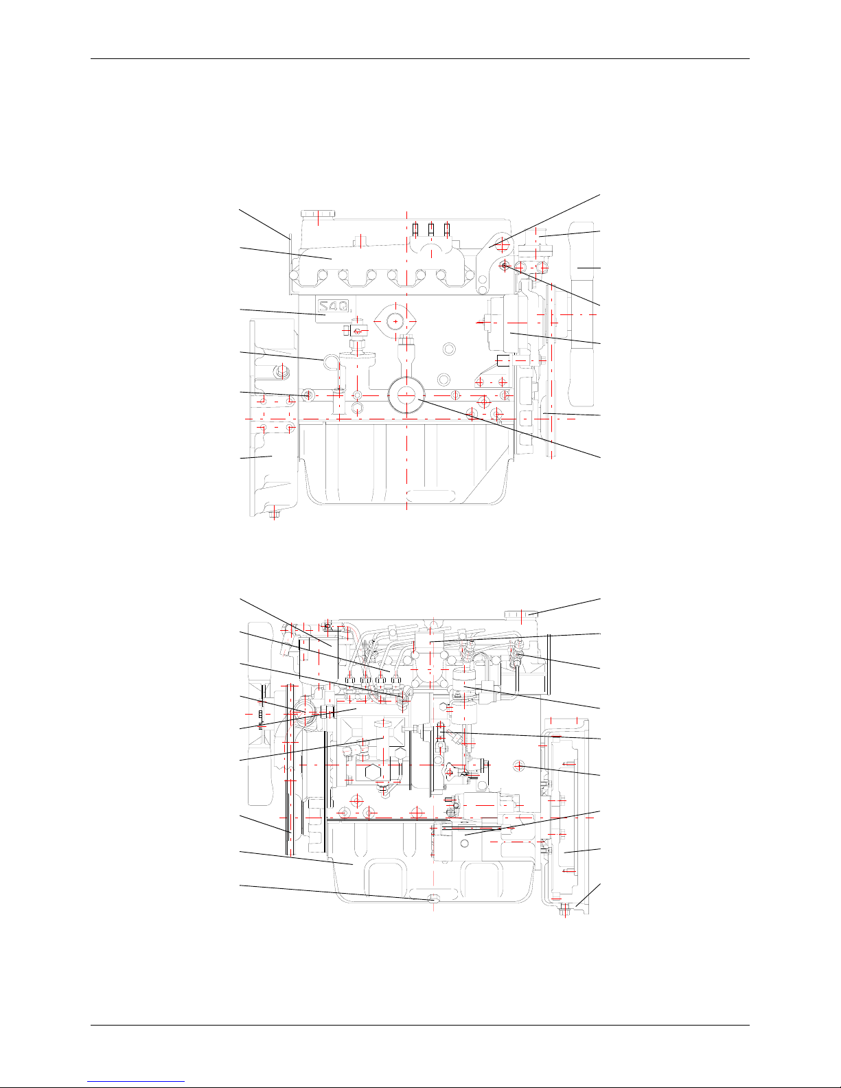
1.1 External View
Thermostat
Hanger
Alternator
Crankshaft pulley
RIGHT SIDE VIEW
Oil filter
Exhaust manifold
Engine serial number
Oil pressure switch
Flywheel housing
REAR
FRONT
Dipstick
Fan
Hanger
Thermoswitch
LEFT SIDE VIEW
REAR
FRONT
Inlet cover
Air vent screw
Oil pan
Speed control lever
Top oil filler
Stop solenoid
Water pump
Fuel injection pump
Fuel filter
V-b elt
Oil drain plug
Fuel feed pump
Coolant drain plug
Starter
Flywheel
Air inlet elbow
Fuel injector
Flywheel housing
9 / 174
Service Manual Mitsubishi SQ-Series diesel engines
Version 08/2004
OUTLINE
ENGLISH
GENERAL
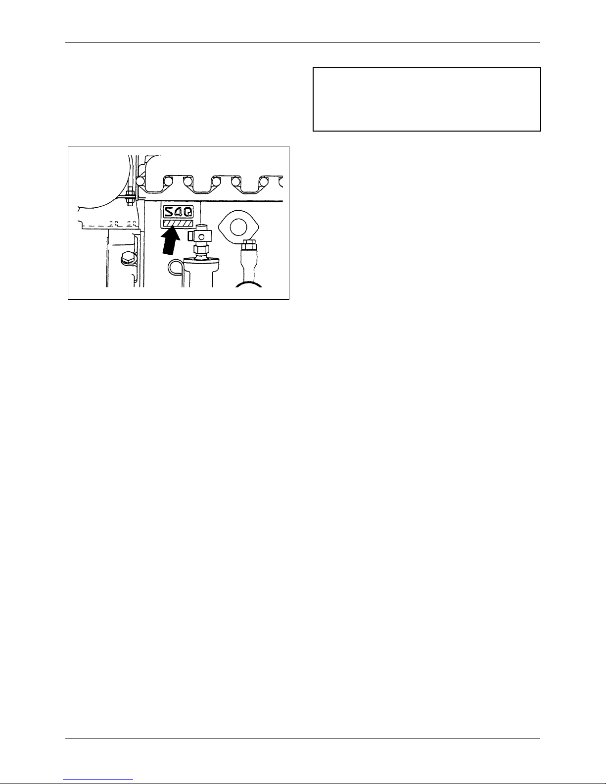
1.2 Engine Serial Number Location
The engine serial number is located on the side of the
crankcase.
1.3 Engine Model and Application
Codes
e.g. S 4 Q
S - Initial of “Sagamihara Machinery Works”
4 - Number-of-cylinders
Q - Series code
Note
Rotation of crankshaft is counterclockwise when seen
from flywheel end.
10 / 174
Service Manual Mitsubishi SQ-Series diesel engines
Version 08/2004
ENGLISH
SPECIFICATIONS GENERAL
GENERAL
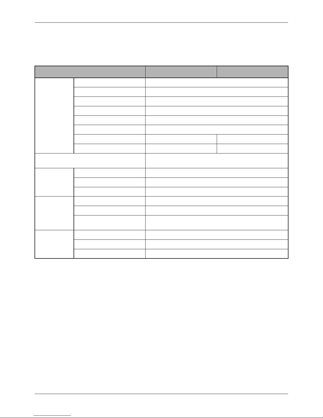
2 SPECIFICATIONS
Engine model S4Q S4Q2
General
Type In-line, water-cooled, 4-stroke cycle
Firing order 1-3-4-2
Compression ratio 22
Combustion chamber type Swirl chamber type
Weight (dry) kg [lb] 195 [430]
Number of cylinders 4
Bore x stroke mm [in.] 88 x 95 [3.46 x 3.74] 88 x 103 [3.46 x 4.06]
Displacement liter [cu in.] 2.311 [141] 2.505 [153]
Maximum permissible working angles for oil pickup
level in oil pan, longitudinal and lateral
10°
Fuel system
Injection pump, type Bosch A
Injection nozzle, type Bosch throttle
Fuel filter, type Spin-on
Lubrication
system
Type Force feed
Oil filter, type Spin-on cartridge of paper-element
Capacity liter [U.S. gal.] Oil pan: 5.5 [1.5], approx.
Crankcase: 6.5 [1.7], approx.
Electrical
system
Starter V-kW 12-2
Alternator V-A 12-50
Battery recommended 12V-92Ah

11 / 174
Service Manual Mitsubishi SQ-Series diesel engines
Version 08/2004
ENGLISH
GENERAL INSTRUCTIONS

12 / 174
Service Manual Mitsubishi SQ-Series diesel engines
Version 08/2004
ENGLISH
DETERMINATION OF OVERHAUL TIMING GENERAL INSTRUCTIONS
GENERAL INSTRUCTIONS
3 DETERMINATION OF
OVERHAUL TIMING
In most cases the engine should be overhauled when
the engineís compression pressure is low. Other
factors that indicated the necessity of engine overhaul
are as follows:
1. Decreased power.
2. Increased fuel consumption.
3. Increased engine oil consumption.
4. Increased blow-by gas volume through the
breather due to abrasion at the cylinder liner and
the piston ring.
5. Gas leakage due to poor seating of the inlet and
the exhaust valves.
6. Starting problems.
7. Increased noise from engine parts.
Any one or a combination of these symptoms may
indicate that engine overhaul is required. Of the items
listed above some are not directly related to the
necessity of engine overhaul. Items (2) and (6) are
more likely to be affected substantially by
• Injection volume of the fuel injection pump
• Fuel injection timing
• Wear of injection-pump plunger
• Fitting of the injection nozzle
• Condition of electrical equipment: battery, starter,
or alternator
Item (4) above, however, requires special consideration
because decreased pressure due to wear at the
cylinder liner and the piston ring is one of the most
obvious signs that the engine requires overhauling.
The most effective way to make a decision is by testing
the compression pressure; other factors are to be
considered secondarily.
13 / 174
Service Manual Mitsubishi SQ-Series diesel engines
Version 08/2004
TESTING THE COMPRESSION
PRESSURE
ENGLISH
GENERAL INSTRUCTIONS
GENERAL INSTRUCTIONS
4 TESTING THE
COMPRESSION
PRESSURE
Start by:
a. Make sure the engine oil, air cleaner, starter
and battery are normal
b. Start the engine and allow it to warm up
thoroughly
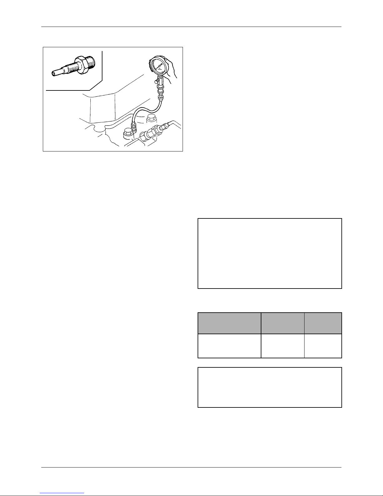
1. Move the stop lever to the stop position.
2. Remove the glow plugs from all cylinder heads.
Connect compression gage (33391-02100) to the
cylinder on which the compression is to be
measured with compression gage adaptor (30691-
21100).
3. Crank the engine with the starter, then read the
compression gage indication while the engine is
running at the specified speed.
4. If the compression pressure is lower than the
repair limit, overhaul the engine.
Unit: MPa (kgf/cm
2
) [psi]
Figure 1 Measuring compression pressure
Compression
gage adapter
CAUTION
a. Measure the compression pressure on all
cylinders.
b. Compression pressure varies with the
engine speed. Check the engine speed
when measuring the compression
pressure.
Item
Assembly
Standard
Repair
Limit
Compression pressure 2.94
(30)
[427]
2.55
(26)
[370]
NOTE
Meaure the compression pressure with the engine
running at 150 to 200 rpm

14 / 174
Service Manual Mitsubishi SQ-Series diesel engines
Version 08/2004
ENGLISH
TESTING THE COMPRESSION
PRESSURE GENERAL INSTRUCTIONS
CAUTION
a. Measure the compression pressure at
regular intervals to obtain correct data.
b. The compression pressure will be slightly
higher in a new or overhauled engine due
to new piston rings, valve seats, etc.
Pressure will drop gradually by the wear
of parts.

15 / 174
Service Manual Mitsubishi SQ-Series diesel engines
Version 08/2004
TIPS ON DISASSEMBLY AND
REASSEMBLY
ENGLISH
GENERAL INSTRUCTIONS
GENERAL INSTRUCTIONS
5 TIPS ON DISASSEMBLY
AND REASSEMBLY
This service manual covers recommended procedures
to be followed when servicing diesel engines. It also
contains information on special tools required and
basic safety precautions.
It is the responsibility of service personnel to be familiar
with these requirements, precautions and potential
hazards and to discuss these points with their foreman
or supervisor.
Study this manual carefully and observe the following
general precautions to prevent serious personal injury
and to avoid damage to the engine, equipment and
parts.
5.1 Disassembly
1. Use the correct tools and instruments. Serious
injury or damage to the engine can result from
using the wrong tools and instruments.
2. Use an overhaul stand or a work bench if
necessary. Also, use assembly bins to keep the
engine parts in order of removal.
3. Lay down the disassembled or cleaned parts in the
order in which they were removed. This will save
you time at reassembly.
4. Pay attention to the marks on assemblies,
components and parts for positions or directions.
Put on your own marks, if necessary, to aid
reassembly.
5. Carefully check each part for faults during removal
or cleaning. Signs of abnormal wear will tell if parts
or assemblies are functioning improperly.
6. When lifting or carrying heavy parts, get someone
to help you if the part is too awkward for one
person to handle. Use jacks and chain blocks
when necessary.
5.2 Reassembly
1. Wash all parts, except for oil seals, O-rings, rubber
seals, etc., in cleaning solvent and dry them with
compressed air.
2. Always use tools that are in good condition and be
sure you understand how to use them before
performing any service work.
3. Use only good quality lubricating oils and greases.
Be sure to apply a coat of oil, grease or sealant to
parts as specified.
4. Use a torque wrench to tighten parts when
specified tightening torques are required.
5. Replace all gaskets and packing.
16 / 174
Service Manual Mitsubishi SQ-Series diesel engines
Version 08/2004
ENGLISH
PRECAUTIONS FOR DISASSEMBLY AND
REASSEMBLY GENERAL INSTRUCTIONS
GENERAL INSTRUCTIONS
6 PRECAUTIONS FOR
DISASSEMBLY AND
REASSEMBLY
6.1 Oil Seals
When installing oil seals, carefully observe the
following points.
6.1.1 Driving oil seals into housings
1. Check the seal lip for damage, and be sure to
position correctly in the housing.
2. Apply a smear of grease to the surface of the oil
seal (to be fitted into the housing bore).
3. Using an oil seal driver shown to guide the seal lip
and drive the outer diameter squarely. To avoid
damage to the oil seal and leaking, never hammer
on it directly.
6.1.2 Driving oil seals onto shafts
1. Apply a smear of grease to the oil seal lip.
2. Use an oil seal guide of the type shown when
driving the oil seal over the stepped portion,
splines, threads, or key way to prevent damage to
the oil seal lip.
6.2 O-rings
Use an O-ring guide to install an O-ring over stepped
parts, splines, threads, or key way to prevent damage
to the ring. Apply a smear of grease to the O-ring
before installation.
Figure 2 Oil seal installer
Figure 3 Oil seal guide
Figure 4 O-ring guide
17 / 174
Service Manual Mitsubishi SQ-Series diesel engines
Version 08/2004
PRECAUTIONS FOR DISASSEMBLY AND
REASSEMBLY
ENGLISH
GENERAL INSTRUCTIONS
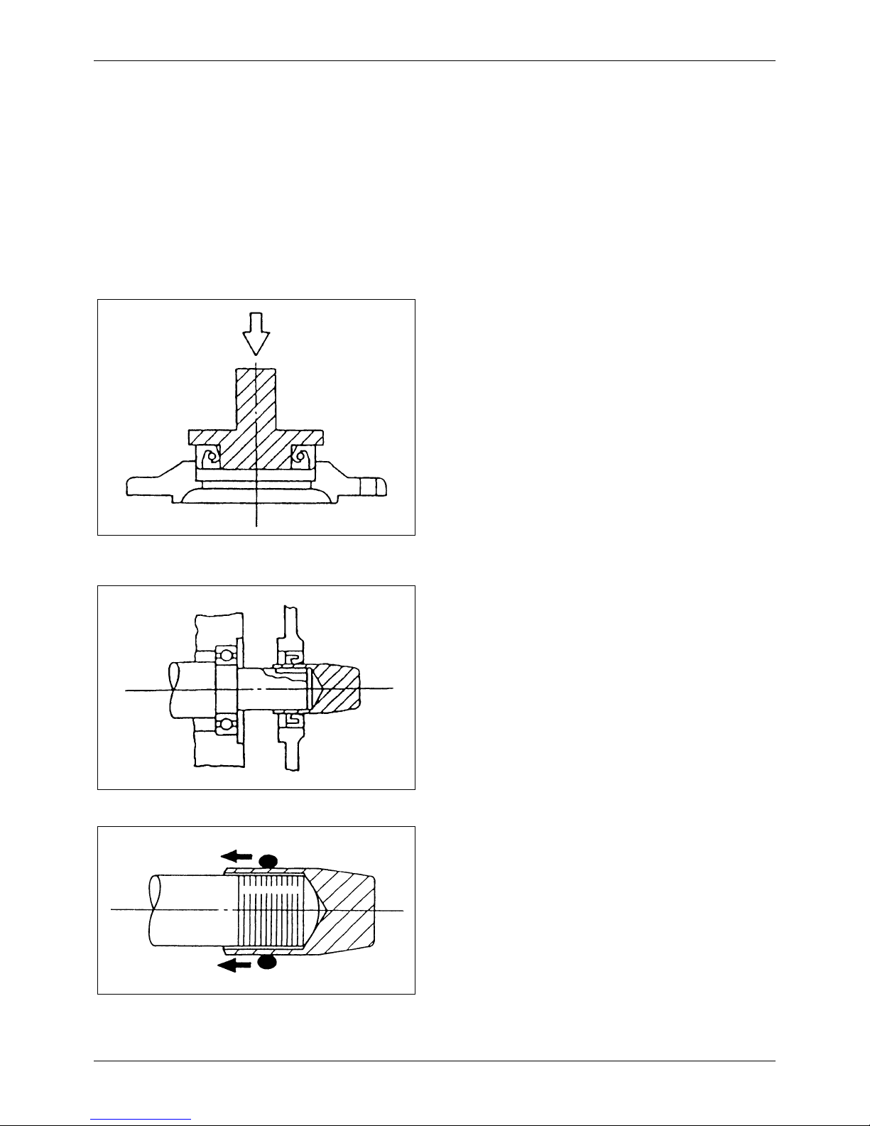
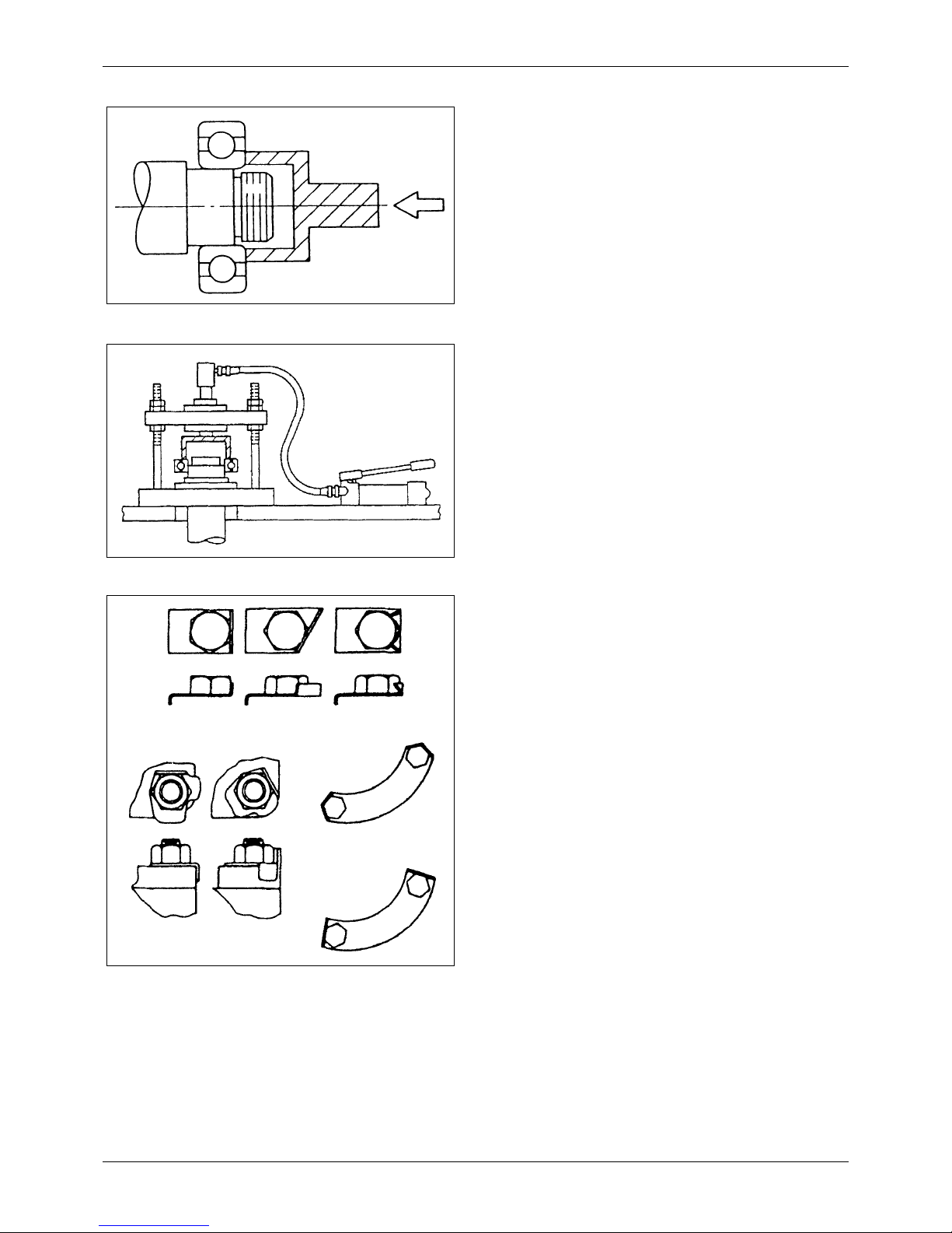
6.3 Bearings
1. When installing a rolling bearing, be sure to push
the inner or outer race by which the bearing is
fitted. Be sure to use a bearing driver like the one
shown.
2. Whenever possible, use a press to minimize shock
to the bearing and to assure proper installation.
6.4 Lock Plates
Bend lock plates against the flats of the nuts or bolt
heads as shown.
6.5 Split Pins and Spring Pins
Generally, split pins are to be replaced once disturbed.
Insert the pin fully and spread it properly. Drive each
spring pin into position to hold it in place after later
installation of parts has been completed.
Figure 5 Bearing driver
Figure 6 Installing a bearing with a press
Figure 7 Bending lock plates
Good Bad
Bad
Good
Good Good Bad

18 / 174
Service Manual Mitsubishi SQ-Series diesel engines
Version 08/2004
ENGLISH
PRECAUTIONS FOR DISASSEMBLY AND
REASSEMBLY GENERAL INSTRUCTIONS

19 / 174
Service Manual Mitsubishi SQ-Series diesel engines
Version 08/2004
ENGLISH
ENGINE MAIN PARTS
20 / 174
Service Manual Mitsubishi SQ-Series diesel engines
Version 08/2004
ENGLISH
CYLINDER HEADS AND VALVE
MECHANISM ENGINE MAIN PARTS
ENGINE MAIN PARTS
7 CYLINDER HEADS AND
VALVE MECHANISM
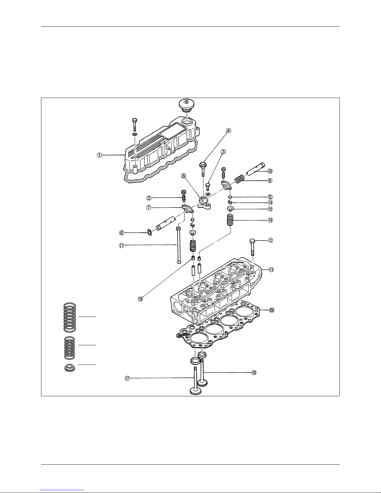
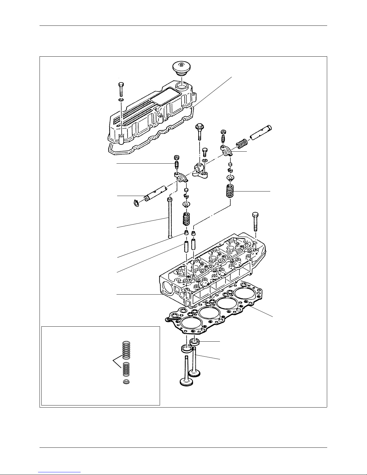
7.1 Disassembly
1. Rocker cover
2. Adjusting screw
3. Bolt (short)
4. Bolt (long)
5. Valve cap
6. Snap ring
7. Rocker arm
8. Rocker shaft bracket
9. Rocker shaft spring
10. Rocker shaft
11. Valve pushrod
12. Cylinder head bolt
13. Cylinder head
14. Valve cotters
15. Upper valve retainer
16. Valve spring
17. Valve (inlet)
18. Valve (exhaust)
19. Valve stem seal
20. Cylinder head gasket
21. Inner valve spring
22. Lower valve spring
High-speed option
16
21
22
21 / 174
Service Manual Mitsubishi SQ-Series diesel engines
Version 08/2004
CYLINDER HEADS AND VALVE
MECHANISM
ENGLISH
ENGINE MAIN PARTS
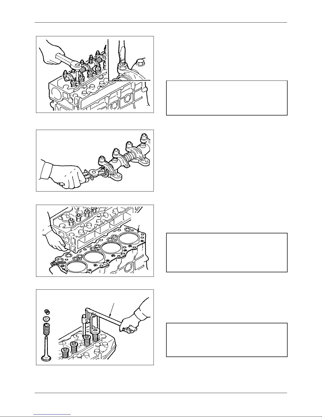
7.1.1 Removing rocker shaft assembly
1) Loosen the adjusting screw one turn.
2) Loosen the bolts, long and short, that hold the
rocker shaft bracket to the cylinder head. Be
sure to loosen the short bolt first. Remove the
rocker shaft assembly from the cylinder head.
7.1.2 Disassembling rocker shaft
assembly
Arrange the disassembled rockers in the order
removed, so you can install them in that order at
reassembly. This will ensure the same rockershaft
clearance as before.
7.1.3 Removing cylinder head
Remove the cylinder head bolts. Lift the head off
the crankcase.
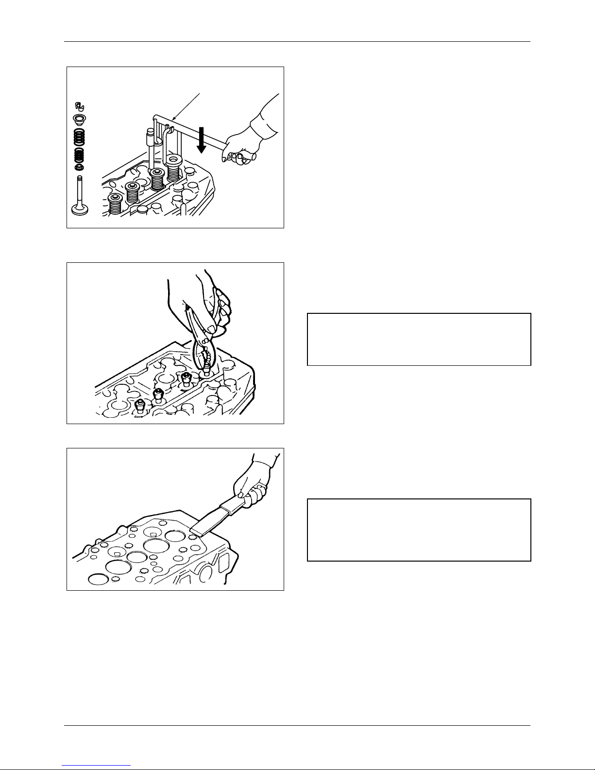
7.1.4 Removing valves and valve springs
Use valve spring pusher (30691-04500) to
compress the valve spring squarely, then remove
the valve cotters.
Figure 8 Removing rocker shaft assembly
CAUTION
If the long bolt is loosened first, the rocker shaft
bracket might suffer damage.
Figure 9 Disassembling rocker shaft assembly
Figure 10 Removing cylinder head
NOTE
If any parts of the cylinder head are faulty, check the
cylinder head bolts for torque with a torque wrench
before removing them.
Figure 11 Removing valves and valve springs
Valv e
spring
pusher
NOTE
If the existing valves are to be reused, put a mark on
each valve for its location.
22 / 174
Service Manual Mitsubishi SQ-Series diesel engines
Version 08/2004
ENGLISH
CYLINDER HEADS AND VALVE
MECHANISM ENGINE MAIN PARTS
7.1.5 Removing valve stem seals
Remove the stem seals with a pliers, as shown in
the illustration.
7.1.6 Cleaning cylinder head
Clean the machined surface of the cylinder head
that makes contact with the gasket.
Figure 12 Removing valves and valve springs (high
speed option)
Valve spring
pusher
Figure 13 Removing valve stem seals
NOTE
Do not reuse the stem seals.
Figure 14 Cleaning cylinder head
NOTE
Remove the gasket with a scraper, then clean the
machined surface with an oilstone and engine oil.
23 / 174
Service Manual Mitsubishi SQ-Series diesel engines
Version 08/2004
CYLINDER HEADS AND VALVE
MECHANISM
ENGLISH
ENGINE MAIN PARTS
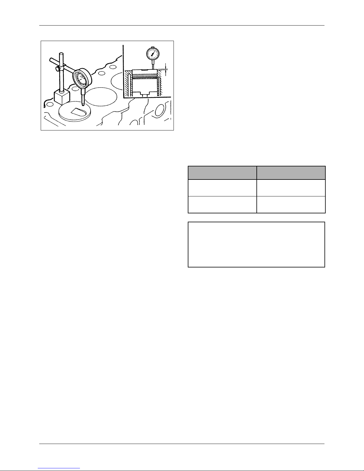
7.1.7 Measuring piston protrusion
1) Determine the top dead center of the piston
with a dial indicator.
2) Install a dial indicator on the crankcase with its
point on the top of the piston. Set the indicator
to read 0 (zero).
3) Check the piston protrusion at three points on
the top of the piston, as shown in the
illustration, and average the three
measurements to determine the protrusion.
Subtract the projection from the compressed
thickness of the gasket to determine the
clearance between the piston top and the
cylinder head.
If the piston protrusion is not correct, check
the various parts for clearance.
Unit: mm [in.]
Figure 15 Measuring piston protrusion
Item Assembly Standard
Piston protrusion
0.13 to 0.60
[0.0051 to 0.0236]
Compressed thickness of
gasket
1.27 to 1.35
[0.0500 to 0.0531]
CAUTION
Incorrect piston protrusion affects engine
performance and causes valve interference with
piston.
24 / 174
Service Manual Mitsubishi SQ-Series diesel engines
Version 08/2004
ENGLISH
CYLINDER HEADS AND VALVE
MECHANISM ENGINE MAIN PARTS
7.2 Inspection
Figure 16 Inspection points
Check surface that makes
contact with walve cap for
wear. Check oil hole for
clogging. Check bushing
for wear.
Check for pitted or
fractured coils. Test
force and length.
Check ends
faces for wear.
Check for bend.
Check for wear.
Check for pitted or fractured
coils. Test force and length.
High speed option
Check face for pitting or ridging (exhaust
valve). Check stem for scratches or scuff
marks.
Replace
Check for uneven wear.
Replace
Replace
Check threads for stripping.
Check surface that makes
contact with valve push rod
for wear.
Check for wear.
Check oil hole for
clogging.
Check for cranks, or
carbon or scale
deposits.
25 / 174
Service Manual Mitsubishi SQ-Series diesel engines
Version 08/2004
CYLINDER HEADS AND VALVE
MECHANISM
ENGLISH
ENGINE MAIN PARTS
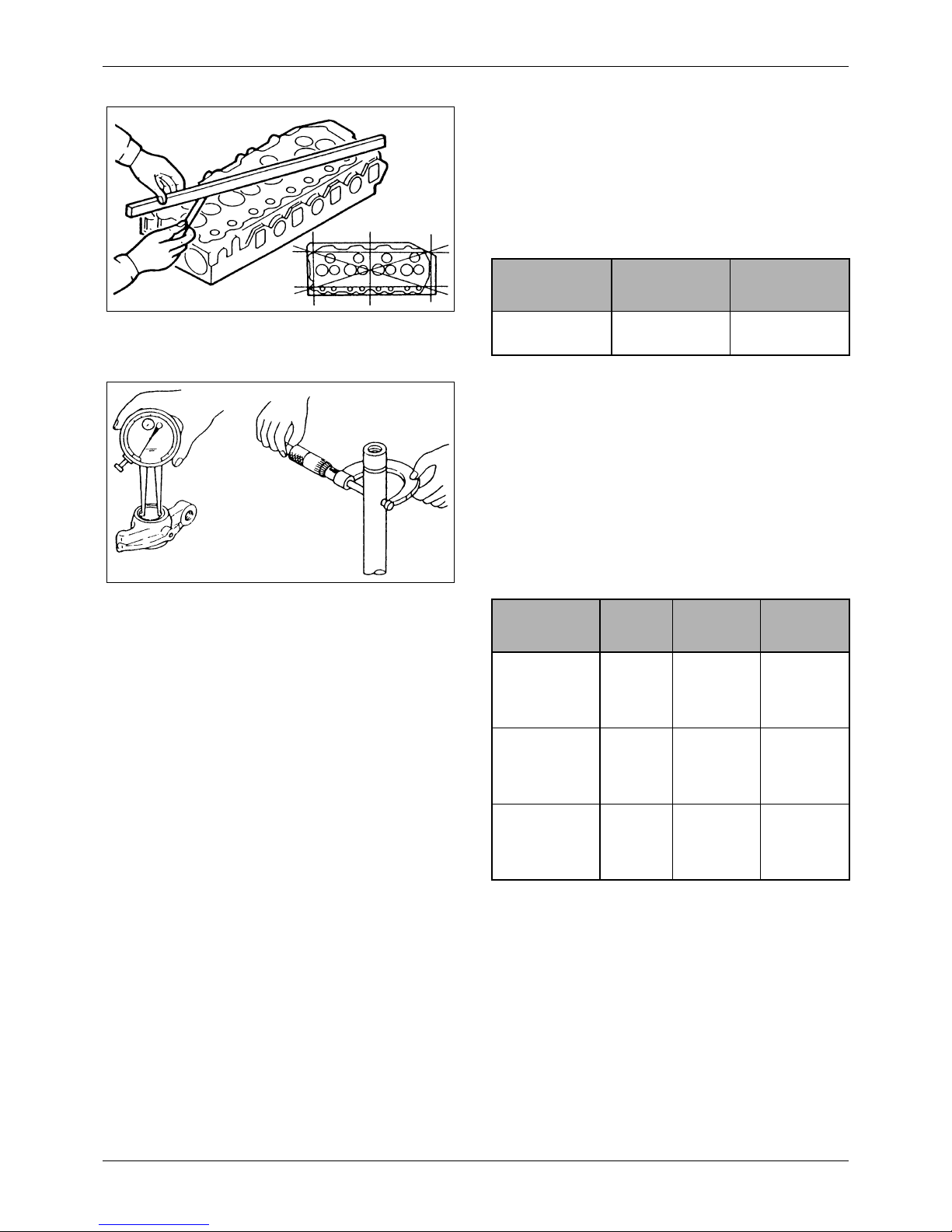
7.2.1 Cylinder head
Using a heavy accurate straight edge and a feeler
gage, check for warpage in three positions lengthwise,
two crosswise and two widthwise, as shown in the
illustration. If warpage exceeds the repair limit, reface
the head with a surface grinder.
Unit: mm [in.]
7.2.2 Rocker arms and rocker shafts
1. Measuring rocker arm bushing and rocker shaft
Measure the inside diameter of the rocker arm
(bushing bore) and the diameter of the rocker
shaft, as shown in the illustration, to check the
clearance between the rocker arm and shaft. If the
clearance is not correct, within the repair limit,
replace the rocker arm. If it exceeds the repair
limit, replace both rocker arm and bushing.
Unit: mm [in.]
Figure 17 Checking cylinder head for warpage
Item
Assembly
Standard
Repair Limit
Warpage of
bottom face
0.05
[0.0020] or less
0.20
[0.0079]
Figure 18 Measuring rocker arm bushing and rocker
shaft
Item
Nominal
Value
Assembly
Standard
Repair
Limit
Inside diameter
of rocker arm
bushing
19
[0.75]
19.010 to
19.030
[0.7484 to
0.7492]
__
Diameter of
rocker shaft
19
[0.75]
18.980 to
19.000
[0.7472 to
0.7480]
__
Clearance
between rocker
bushing and
shaft
__
0.010 to
0.050
[0.0004 to
0.0020]
0.070
[0.0028]
26 / 174
Service Manual Mitsubishi SQ-Series diesel engines
Version 08/2004
ENGLISH
CYLINDER HEADS AND VALVE
MECHANISM ENGINE MAIN PARTS
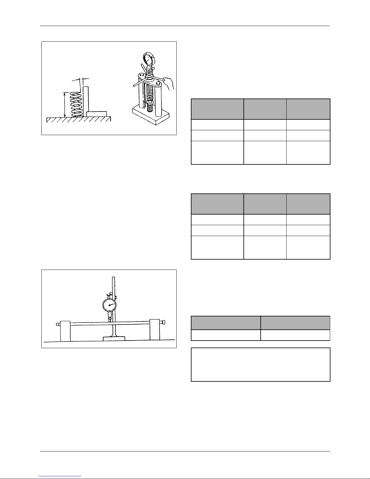
2. Measuring valve spring perpendicularity and free
length
Measure the free length and perpendicularity of
each valve spring. If the free length or
perpendicularity exceeds the service limit, replace
the spring.
Unit: mm [in.]
Inner valve spring (high-speed option)
Unit: mm [in.]
7.2.3 Valve pushrods
Using V-blocks and a dial indicator, check for runout, as
shown in the illustration. If runout exceeds the
assembly standard, replace the pushrod.
Unit: mm [in.]
Figure 19 Measuring valve spring perpendicularity
and free length
Free
length
Perpendicularity
Item
Assembly
Standard
Service Limit
Free length 48.85 [1.92] 47.60 [1.87]
Perpendicularity 1.5° or less __
Set force N (kgf)
[lbf]
177 to 196
(18 to 20)
[40 to 44]
147
(15)
[33]
Item
Assembly
Standard
Service Limit
Free length 50.0 [1.9685] 49.0 [1.9291]
Perpendicularity 1.5° or less __
Set force N (kgf)
[lbf]
56.9
(5.8)
[12.8]
48.1
(4.9)
[10.8]
Figure 20 Measuring valve pushrod runout
Item Assembly Standard
Pushrod runout 0.3 [0.012] or less
NOTE
Assembly standards refer to dial gage readings.
27 / 174
Service Manual Mitsubishi SQ-Series diesel engines
Version 08/2004
CYLINDER HEADS AND VALVE
MECHANISM
ENGLISH
ENGINE MAIN PARTS
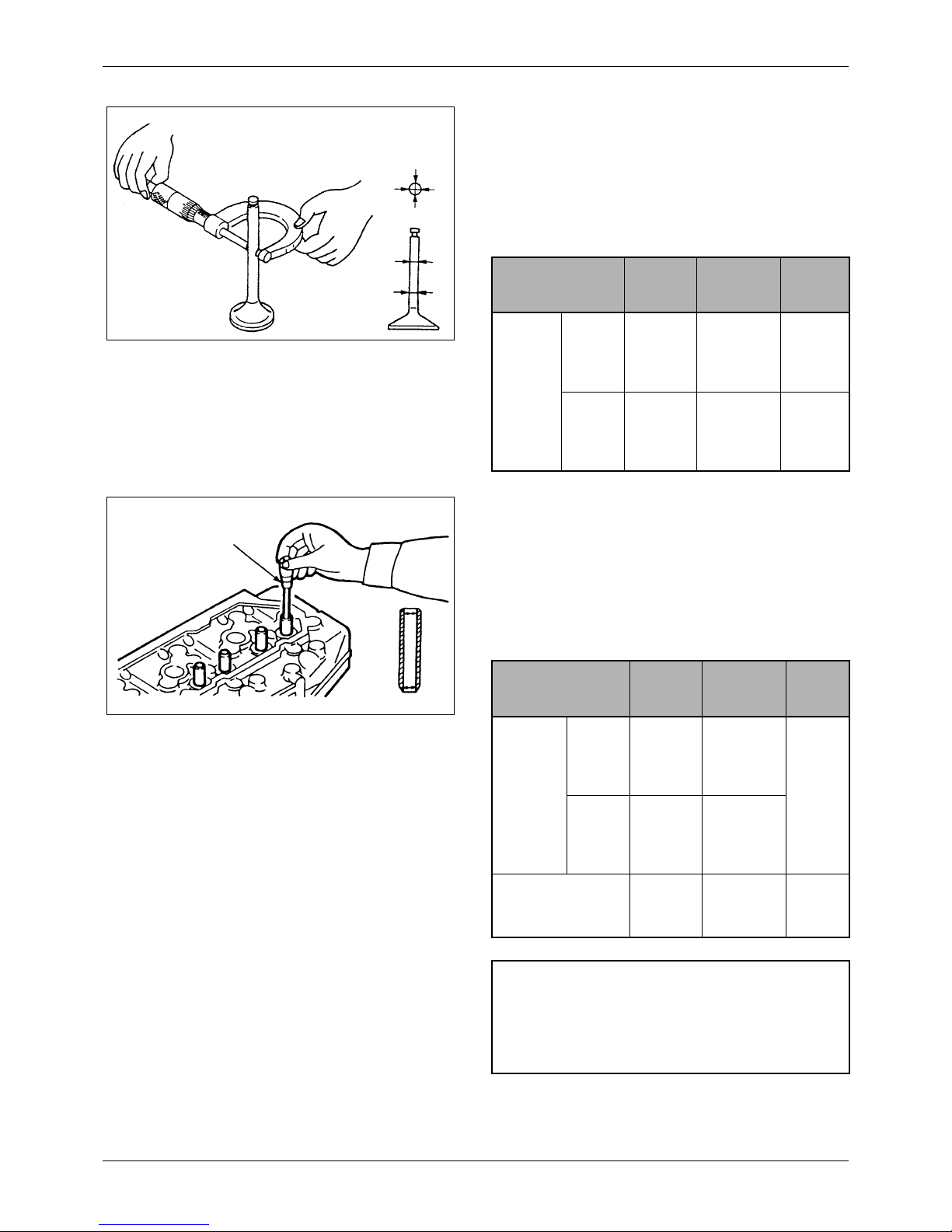
7.2.4 Valves, valve guides and valve seats
1. Measuring valve stem
Measure the diameter of the valve stem, as shown
in the illustration. If the service limit is exceeded,
replace the valve.
Unit: mm [in.]
2. Checking clearance between valve stem and guide
The valve guide wears more rapidly at its both
ends than at any other parts. Measure the inside
diameter of the valve guide at its ends, as shown in
the illustration, to check the clearance. If the
clearance exceeds the service limit, replace the
guide or valve whichever is badly worn.
Unit: mm [in.]
Figure 21 Measuring valve stem
Measuring
directions
Measuring points
Item
Nominal
Value
Assembly
Standard
Service
Limit
Val ve
stem
diameter
Inlet
valves
8
[0.315]
7.940 to
7.955
[0.3126 to
0.3132]
7.900
[0.3110]
Exhaust
valves
8
[0.315]
7.920 to
7.940
[0.3118 to
0.3126]
7.850
[0.3091]
Figure 22 Measuring valve guide
Inside micrometer caliper
Item
Nominal
Value
Assembly
Standard
Repair
Limit
Clearance
between
valve
stem and
guide
Inlet
valves
__
0.065 to
0.095
[0.0026 to
0.0037]
0.200
[0.0079]
Exhaust
valves
__
0.080 to
0.115
[0.0032 to
0.0045]
Height to top of valve
guide
15.5
[0.61]
15.1 to 15.6
[0.5945 to
0.6142]
__
NOTE
Before measuring the valve guides, clean the guides,
removing lacquer or other deposits by running wire
brush through them.

28 / 174
Service Manual Mitsubishi SQ-Series diesel engines
Version 08/2004
ENGLISH
CYLINDER HEADS AND VALVE
MECHANISM ENGINE MAIN PARTS
3. Replacing valve guide
1) To remove the valve guide for replacement,
use valve guide remover (32A91-00300).
2) To install a replacement valve guide, use valve
guide installer (32A91-00100) and a press.
3) Insert a new valve into the guide just installed
to check how the valve slides in the guide.
4) After replacing the valve guides, check the
valve contact with the seats.
4. Inspecting valve face
Coat the valve face lightly with red lead. Use the
Valve lapper to inspect the valve contacts with its
seat. If the contact is not uniform, or if the valve is
defective or if the service limit is exceeded, repair
or replace the valve and valve seat.
Figure 23 Replacing valve guide
Valve guide remover
Val ve
guide
CAUTION
The height to top of valve guide is specified; be sure
to use the valve guide installer to insure the correct
height.
Figure 24 Installing valve guide
Press
15.5 mm
[0.61 in.]
Valve guide installer
Valve guide
Figure 25 Inspecting valve face
Valve lapper
Red lead
29 / 174
Service Manual Mitsubishi SQ-Series diesel engines
Version 08/2004
CYLINDER HEADS AND VALVE
MECHANISM
ENGLISH
ENGINE MAIN PARTS
Unit: mm [in.]
S
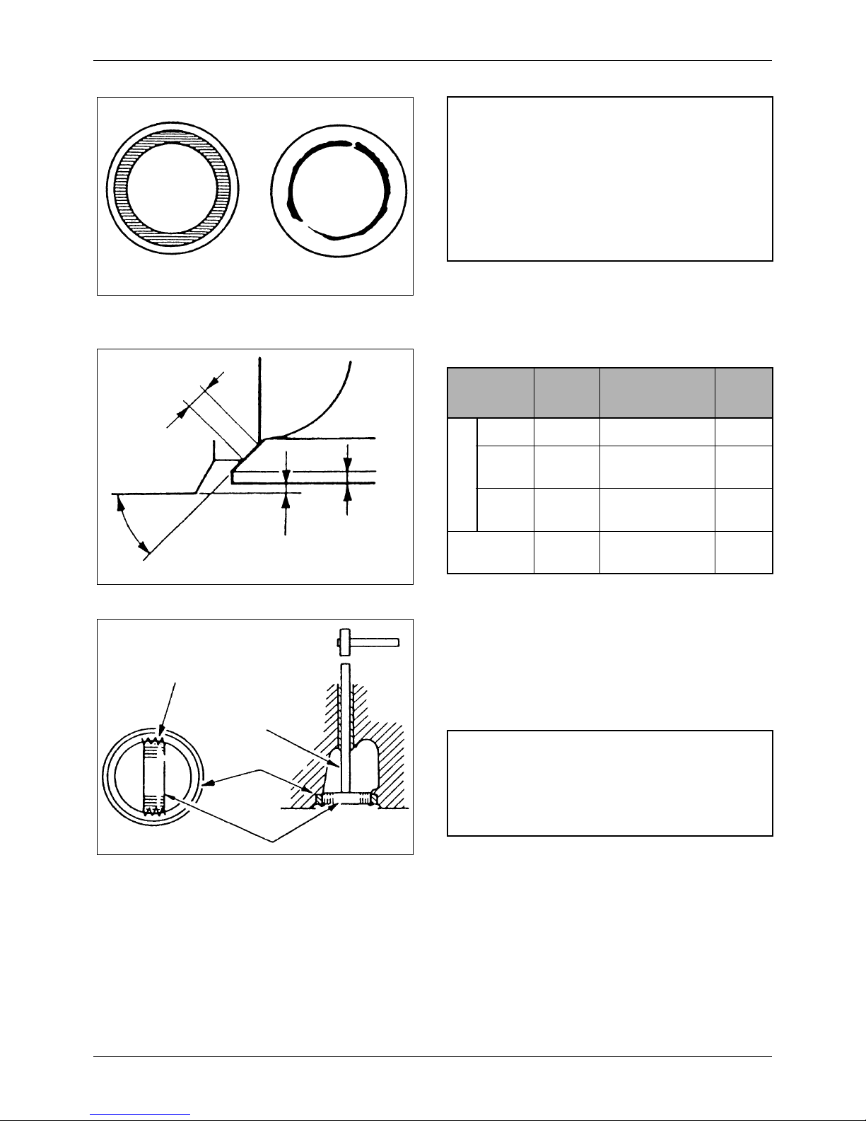
5. Replacing valve seat
1) Weld a stud to the valve seat. Insert a shaft
through the valve guide from the upper side of
the cylinder head to put its end on the stud, as
shown in the illustration. Then, drive the seat
off from the cylinder head.
Figure 26 Valve contact pattern
Good Bad
NOTE
a Check the valve contact after checking or
replacing the valve guides.
b Do not rotate the valve when holding it
against the seat for checking the contact.
c After refacing or replacing the valve or valve
seat, lap the valve in the seat. (See (8)
Lapping valves.)
Figure 27 Valve contact with valve seat
Valve seat angle
Val ve
sinkage
Valve seat width
Val ve
margin
Item
Nominal
Value
Assembly
Standard
Repair
Limit
Valve seat
Angle 30°
Width
1.18
[0.05]
1.04 to 1.32
[0.0409 to 0.0520]
1.6
[0.0630]
Val ve
sinkage
0.8
[0.03]
0.7 to 0.9
[0.0276 to 0.0354]
1.3
[0.0512]
Valve margin
1.70
[0.07]
1.20
[0.0472]
Figure 28 Replacing valve seat
Weld
Bar
Valve seat
Stud
Valve seat
NOTE
When welding the stud to the valve seat, avoid
contact of any spatter with the machined surface of
the cylinder head.
30 / 174
Service Manual Mitsubishi SQ-Series diesel engines
Version 08/2004
ENGLISH
CYLINDER HEADS AND VALVE
MECHANISM ENGINE MAIN PARTS
2) Before inserting a new valve seat, measure
the bores in the cylinder head for the valve
seats to make sure they are correct in
dimension.
3) Chill the valve seat in liquid nitrogen (about –
170°C [–274°F]) for more than 4 minutes with
the cylinder head kept at normal temperature,
or heat the cylinder head to 80 to 100°C [176
to 212°F] with the valve seat chilled in ether or
alcohol containing dry ice.
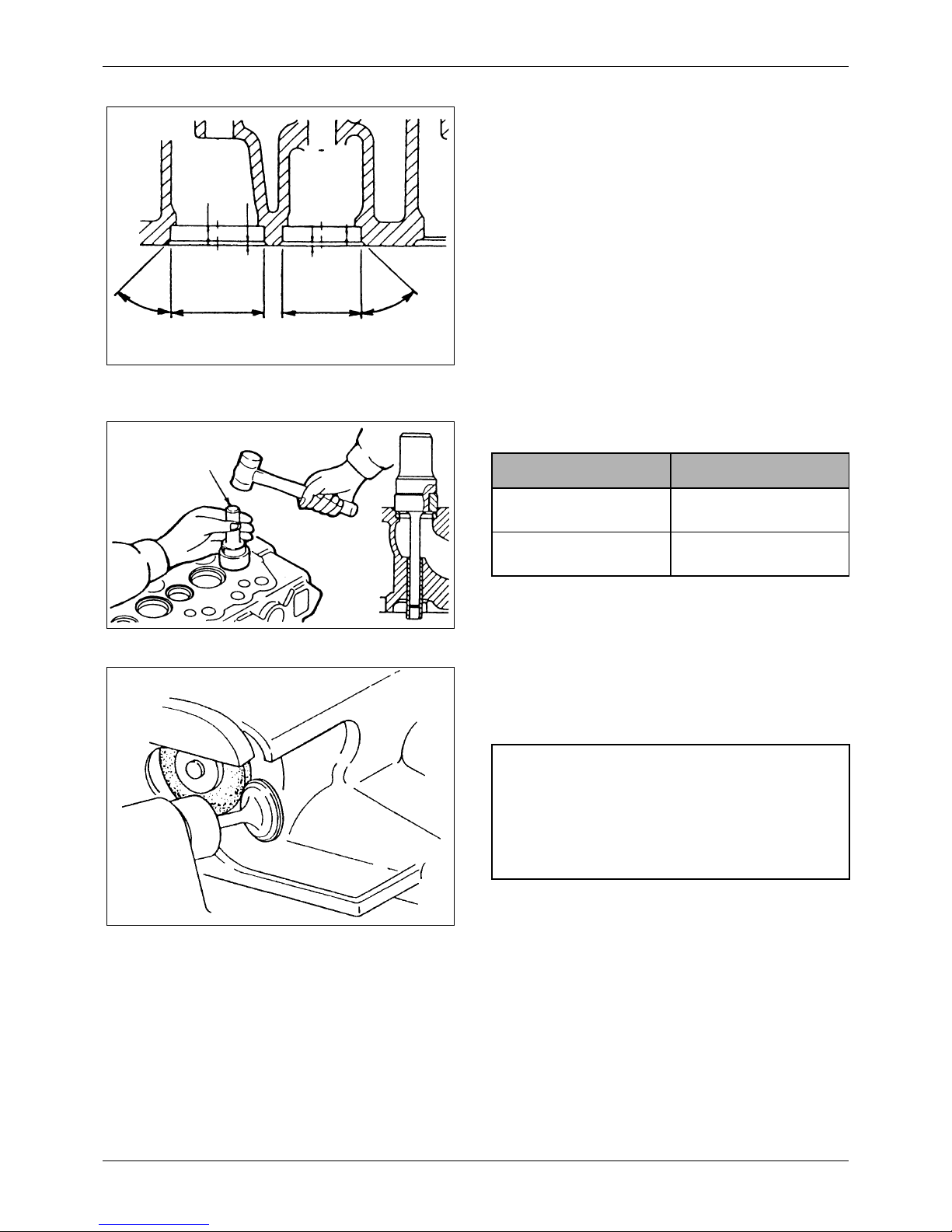
4) Use the caulking tool to install the valve seat.
Tools needed
6. Refacing valve face
If the valve face is badly worn, reface it with a
valve refacer.
Figure 29 Valve seat bore dimensions
Unit: mm [in.]
Inlet valve
seat bore
Exhaust valve
seat bore
45°45°
8.8 ± 0.1
[0.346 ± 0.004]
8.8±0.1
[0.346 ± 0.004]
2.8 ± 0.1
[0.11 ± 0.004]
2.8 ± 0.1
[0.11 ± 0.004]
41
[1.61 ]
+0.02
0
+0.0008
0
33
[1.30 ]
+0.02
0
+0.0008
0
Figure 30 Installing valve seat
Caulking tool
Part number
Caulking tool (for inlet valve
seat)
30691-02700
Caulking tool (for exhaust
valve seat)
30691-02800
Figure 31 Refacing valve face
NOTE
a Set a valve refacer at an angle of 30°.
b Grind the valve as little as possible. If the
margin seems to exceed the repair limit as a
result of grinding, replace the valve.
 Loading...