

Page 1
September 2012
Pub. No. 99400-71100
The operator and supervisor are requested to read this Oper-
ation and Maintenance Manual carefully before operating the
engine or conducting inspection and maintenance.
Never operate the engine or conduct maintenance work with-
out completely understanding this manual.
OPERATION &
MAINTENANCE MANUAL
1
Page 2

Page 3

i
INTRODUCTION
This operation and maintenance manual contains detailed operation, inspection
and maintenance information for engines from Mitsubishi Heavy Industries, Ltd.
Please be noticed that some contents are repeated among chapters for better
understanding.
Please read and understand this manual before proceeding with operation,
inspection, and maintenance work.
Failure to follow instructions in this manual may result in serious accidents.
Please observe the contents of the controls which are applied in the countries or
areas when using the engines from Mitsubishi Heavy Industries, Ltd.
Page 4

ii
FOREWORD
Limited Warranty
If Mitsubishi Heavy Industries, Ltd. examines the returned parts and any failure at manufacturing is found, Mitsubi-
shi Heavy Industries, Ltd. shall repair or exchange the parts.
Mitsubishi Heavy Industries, Ltd.'s warranty is limited to the compensation work of repair or replacement of parts.
The warranty coverage is effective for the original purchaser only. Those to whom ownership is later transferred are
not provided with the warranty. However the warranty coverage is effective for the ultimate purchaser and each sub-
sequent purchaser for emission-related parts.
Mitsubishi Heavy Industries, Ltd. makes no warranties, either expressed or implied,
except as provided in this manual, including, but not limited to, warranties as to marketability , merchant ability, fitness for a p articular purpose or use, or against infringement of
any patent.
Mitsubishi Heavy Industries, Ltd. will not be liable for any damages or consequential
damages, including, but not limited to, damages or other cost s resulting from any abuse,
misuse, misapplication of the engine and devices supplied from us.
Mitsubishi Heavy Industries, Ltd. will not be liable for any damages or personal injuries
resulting from any modification, without our written permission, of the engine and
devices supplied from us.
Mitsubishi Heavy Industries, Ltd. will not be liable for any damages or production losses
caused by the use of fuel, engine oil and/or coolant (LLC) that we are not recommended.
The owner of the engine is responsible for the perf orm ance of th e r equir ed maintenance
listed in this operation manual.
When performing the maintenance, follow the service manual published by Mitsubishi
Heavy Industries, Ltd.
Mitsubishi Heavy Industries, Ltd. may deny the warranty coverage if the engine or part
has failed due to inadequate or improper maintenance.
Page 5

iii
FOREWORD
Important Information
To avoid the potential hazard, accident prevention
activities must be planned methodically and con-
ducted continually by considering all aspect of
engine operation, maintenance and inspection. All
related personnel, including managers and supervi-
sors, should actively participate, recognize their roles
and organize themselves and their work to ensure a
safe environment.
The foremost safety objective is to prevent accidents
which may result in injury or death, or equipment
damage.
Always observe laws or regulations of the local or
federal/national government.
Mitsubishi Heavy Industries, Ltd. cannot foresee all
potential dangers of the engine, potential dangers
resulting from human error and other causes, or a
danger caused by a specific environment in which
the engine is used. Since there are many actions that
cannot be performed or must not be performed, it is
impossible to indicate every caution in this manual or
on warning labels. As such, it is extremely important
to follow instructions in this manual and also to take
general safety measures when operating, maintain-
ing and inspecting the engine.
When the engine is used by individuals whose native
language is not English, the customer is requested to
provide thorough safety guidance to the operators.
Also attach safety, caution and operating decals that
describe the original warning label statements in the
native language of the operators.
The engine must be operated, maintained and
inspected only by qualified persons who have thor-
ough knowledge of engines and their dangers and
who also have received risk avoidance training.
To prevent an accident, do not attempt to carry out
any operation other than those described in this man-
ual, and do not use the engine for any unapproved
purpose.
When the ownership of the engine is transferred, be
sure to give this manual to the new owner though we
do not warrant the engine. Also inform Mitsubishi
Heavy Industries, Ltd. of the name and address of
the new owner of the engine.
This manual is copyrighted and all rights are
reserved. No part of this manual, including illustra-
tions and technical references, may be photocopied,
translated, or reproduced in any electronic medium
or machine readable form without prior written con-
sent from Mitsubishi Heavy Industries, Ltd.
For improvement of the engine, the contents in this
manual are subject to change at any time without
notice.
Pictures or illustrations of the product in this manual
may differ from those of the product you have.
Please note that, depending on specifications, items
described in this manual may differ from those on
your engine in shape, or may not be installed on your
engine.
Please contact your local dealer if you need more
information, or if you have any questions.
If the manual is lost or damaged, please obtain a new
copy at a dealer of Mitsubishi Heavy Industries, Ltd.
as soon as possible.
Mitsubishi Heavy Industries, Ltd. recommends the
engine owner to install an hour meter on the engine
so that you can learn the exact engine operating
time, thereby performing the specified maintenance
at the appropriate time as described herein.
Page 6
iv
FOREWORD
Warning Indication
The following signs and symbols are used to call attention of the operators and maintenance personnel to potential
dangers of the engine.
Warning statements in the manual
Warning labels affixed on the engine
Warning Statements
The warning statements in this manual describe potential danger in operating, inspecting or maintaining the engine,
using the following five classifications to indicate the degree of potential hazard.
Failure to follow these directions could lead to serious accidents which could result in personal injury, or death in the
worst case.
Understand the directions well, and handle engines by following directions.
Indicates an immediately hazardous situation which, if not avoided, will result in death or
serious injury.
Indicates a potentially hazardous situation which, if not avoided, could result in death or
serious injury.
Indicates a potentially hazardous situation which, if not avoided, may result in minor or
moderate injury.
Indicates a potentially hazardous situation which, if not avoided, may result in property
damage.
Note: Indicates important information or information which is useful for engine operation.
Page 7

v
FOREWORD
Units of Measurment
Measurements are based on the International System of Units (SI), and they are converted to the metric system
units in this manual. Conversion rates are as follows:
Pressure: 1 MPa = 10.197 kgf/cm
2
Torque: 1 N•m = 0.10197 kgf•m
Force: 1 N = 0.10197 kgf
Horsepower: 1 kW = 1.341 HP = 1.3596 PS
Rotation speed: 1 min
-1
= 1 rpm
Kinetic viscosity: 1 mm
2
/s = 1 cSt
Abbreviations, Standards and Others
API = American Petroleum Institute
ASTM = American Society for Testing and Materials
ISO = International Organization for Standardization
JIS = Japanese Industrial Standards
LLC = Long Life Coolant
MIL = Military Specifications and Standards
MSDS = Material Safety Data Sheet
SAE = Society of Automotive Engineers
Page 8

Page 9

CONTENTS-1
CONTENTS
Chapter 1
BASIC SAFETY PRECAUTIONS
Fire and Explosions.............................1-1
Keep Flames Away .......................................... 1-1
Always Place the Water Heater Switch in
the ON Position (Emergency Generator With
Water Heater).................................................. 1-1
Keep Engine Surrounding Area Tidy and
Clean................................................................ 1-1
Ventilation of Engine Room.............................. 1-1
Do Not Open Side Cover Until Engine Cools... 1-2
Watch Out for Leaks of Fuel, Oil and
Exhaust Gas..................................................... 1-2
Use Explosion-Proof Lighting Apparatus ......... 1-2
Prevent Electrical Wires From Short-Circuiting 1-2
Keep Fire Extinguishers and a First-Aid Kit
Handy............................................................... 1-2
Stay Clear of All Rotating and
Moving Parts........................................1-3
Install Protective Covers Around Rotating
Parts................................................................. 1-3
Check Work Area for Safety............................. 1-3
Stay Clear of Moving Parts During Operation.. 1-3
Lockout and Tagout ......................................... 1-3
Stop the Engine Before Servicing .................... 1-3
Always Restore Engine Turning Tools
After Use ......................................................... 1-3
Watch Out for Exhaust Fume
Poisoning.............................................1-4
Operate Engine in a Well-ventilated Area........ 1-4
Protect Ears From Noise .....................1-4
Wear Ear Plugs ................................................ 1-4
Watch Out for Falling Down.................1-4
Lift Engine Carefully......................................... 1-4
Do Not Climb Onto Engine............................... 1-4
Always Prepare Stable Scaffold....................... 1-4
Be Careful Not Burn Yourself ..............1-5
Do Not Touch the Engine During or Immediately
After Operation................................................. 1-5
Refill Coolant Only After the Coolant
Temperature Lowered...................................... 1-5
Be Careful of Burns When Changing Oil.......... 1-5
Never Remove Heat Shields............................ 1-5
Be Careful When Opening and Closing of
Radiator Cap .................................................... 1-5
Do Not Touch a High Pressure Fuel Jet .......... 1-5
Be Careful When Handling Fuel,
Engine Oil and Coolant (LLC)..............1-6
Use Only Specified Fuel, Engine Oil and LLC.. 1-6
Handle LLC Carefully ....................................... 1-6
Proper Disposal of Waste Oil, LLC and
Coolant............................................................ 1-6
If Problem Occurs ............................... 1-6
Stop Operation Immediately If You Notice
Any Unusual Symptoms ................................... 1-6
Do Not Add Coolant Immediately After a Sudden
Stop Due To Overheating ................................ 1-6
Avoid Restart Immediately After Abnormal
Stop................................................................. 1-6
Avoid Continuous Engine Operation at
Low Oil Pressure.............................................. 1-6
If Belt Breaks, Stop Engine Immediately .......... 1-6
Battery................................................. 1-7
Handle Battery Correctly .................................. 1-7
Other Cautions.................................... 1-8
Never Modify Engine ........................................ 1-8
Observe Safety Rules at Work Site.................. 1-8
Wear Clothing and Protective Gear ................. 1-8
Never Break Seals ........................................... 1-8
Perform All Specified Pre-operation Inspections
and Periodic Inspections .................................. 1-8
Break-in Engine................................................ 1-8
Warm-up Engine Before Use ........................... 1-8
Conduct Cooling Operation Before Stopping
the Engine ........................................................ 1-8
Never Operate the Engine Under Over Load... 1-9
Do Not Operate Engine Continuously Under Low
Load ................................................................. 1-9
Protection of Engine Against Water Entry ........ 1-9
Conduct Proper Maintenance of Air Cleaner or
Pre-cleaner....................................................... 1-9
Use of Tools Optimum for Each Work.............. 1-9
Avoidance of Prolonged Starting Operation..... 1-9
Do Not Turn Off the Battery Switch During
Operation ....................................................... 1-10
Precautions for Transporting Engines............ 1-10
Warning Labels ................................. 1-11
Maintenance of Warning Labels..................... 1-11
Chapter 2
NAME OF PARTS
Engine External Views ........................ 2-1
Front View ........................................................ 2-1
Rear View......................................................... 2-1
Left View .......................................................... 2-2
Right View ........................................................ 2-2
Page 10

CONTENTS
CONTENTS-2
Equipment and Instrument ..................2-3
Start and Stop Instrument ................................ 2-3
Transmitters to Instruments ............................. 2-4
Engine Protection Devices ..................2-5
Thermo Switch ................................................. 2-5
Oil Filter Differential Pressure Alarm Switch .... 2-5
Air Cleaner Indicator ........................................ 2-5
Using Manual Turning Gear ................2-6
Chapter 3
OPERATION
Operational Environment.....................3-1
Preparation for Operating New or
Overhauled Engine..............................3-1
Preparation of Fuel System.............................. 3-1
Preparation of Lubrication System ................... 3-4
Preparation for Cooling System ....................... 3-5
Preparation of Electrical System ...................... 3-7
Test Operation ................................................. 3-9
Normal Engine Operation ..................3-10
Preparations for Operation ................3-10
Engine External - Inspect............................... 3-10
Fuel Tank Oil Level - Check........................... 3-10
Fuel Tank - Drain Water................................. 3-11
Fuel Control Link - Check............................... 3-11
Engine Oil Level - Check................................ 3-12
Coolant Level - Check.................................... 3-12
Air Cleaner - Check for Clogging ................... 3-13
Temperature of Damper - Check ................... 3-13
Starting-up.........................................3-14
Warm-up Operation...........................3-14
Engine Oil Pressure - Check.......................... 3-14
External Inspection During Warm-up ............. 3-14
Operation...........................................3-15
Cautions During Operation............................. 3-15
Inspection During Operation .......................... 3-15
Stopping ............................................3-16
Emergency Stop............................................. 3-16
Inspection After Stopping ............................... 3-16
Chapter 4
FUEL
Recommended Fuel ............................4-1
Handling Fuel ......................................4-1
Fuel Specification ................................4-2
Chapter 5
ENGINE OIL
Recommended Engine Oil .................. 5-1
Engine Oil Grade ................................ 5-1
Engine Oil Specifications .................... 5-2
Selection of Oil Viscosity..................... 5-3
Handling Engine Oil ............................ 5-4
Service Limits of Engine Oil ................ 5-4
Definition of Properties of Engine Oil .. 5-5
Kinetic Viscosity ............................................... 5-5
Base Number ................................................... 5-5
Acid Number .................................................... 5-5
Water Content .................................................. 5-6
Flash Point ....................................................... 5-6
Insolubles ......................................................... 5-6
Engine Oil Analysis Service ................ 5-7
Chapter 6
COOLANT
Recommended Water for Coolant ...... 6-1
Long Life Coolant (LLC)...................... 6-1
Genuine LLC....................................... 6-1
Other Brand LLCs ............................... 6-2
Requirements for Other Brand LLC .... 6-2
General Quality Requirements for LLC ............ 6-2
LLC Quality Requirements ............................... 6-3
Maintenance of LLC............................ 6-6
Replacement Intervals of LLC .......................... 6-6
LLC Concentration (GLASSY, PG GLASSY)... 6-7
Importance of LLC .............................. 6-8
Characteristics of LLC Additive and
Points to Remember ........................... 6-8
Examples of Abnormalities Caused by
LLC (Amine Type).............................. 6-8
Pitting of Iron Parts........................................... 6-8
Corrosion of Aluminum Parts ........................... 6-8
Pitting and Clogging of Radiator ...................... 6-8
Chapter 7
MAINTENANCE SCHEDULE
How to Use Maintenance Schedule.... 7-1
General Definition of Engine ............... 7-2
Periodic Maintenance Chart for
Regular (Prime) Use Engine ............... 7-3
Page 11

CONTENTS-3
CONTENTS
Periodic Maintenance Chart for
Emergency Engine .............................7-5
Chapter 8
PERIODIC INSPECTION AND
MAINTENANCE PROCEDURES
Basic Engine........................................8-1
Engine External - Inspect................................. 8-1
Belt and Belt Tension - Inspect and Adjust ...... 8-2
Damper - Inspect.............................................. 8-5
Fuel System.........................................8-7
Fuel System - Inspect ...................................... 8-7
Fuel Tank - Clean............................................. 8-7
Fuel Tank - Drain Water................................... 8-7
Oil-water Separator - Drain Water.................... 8-8
Oil-water Separator Element - Replace ........... 8-8
Gauze Filter - Clean ......................................... 8-9
Fuel Filter - Replace....................................... 8-10
Fuel Control Link Ball Joint - Inspect.............. 8-11
Fuel Pipe - Inspect ......................................... 8-12
Lubrication System............................8-13
Engine Oil, Oil Filter and Bypass Oil Filter -
Replace.......................................................... 8-13
Fuel and Water Ingress In Engine Oil -
Inspect .......................................................... 8-16
Oil Pipe - Inspect............................................ 8-16
Cooling System .................................8-17
Coolant - Change ........................................... 8-17
Inlet and Exhaust Systems................8-21
Turbocharger - Inspect................................... 8-21
Pre-cleaner - Clean, Inspect and Replace ..... 8-21
Air Cleaner Element - Clean, Check and
Replace ......................................................... 8-22
Electrical System...............................8-24
Starter - Inspect.............................................. 8-26
Alternator - Inspect......................................... 8-26
Chapter 9
LONG-TERM STORAGE
Storing Engine in an Inoperable
Condition for 3 Months up to 1 Year....9-1
Preparation for Storage.................................... 9-1
Maintenance During Storage ........................... 9-2
When Using Engine After Storage ................... 9-2
Storing Engine in an Operable
Condition ............................................9-2
Operating Engine for Maintenance .................. 9-2
Chapter 10
TRANSPORTATION
Lifting Engine .................................... 10-1
Chapter 11
TROUBLESHOOTING
General Precautions ......................... 11-1
Contact a Dealer of Mitsubishi Heavy Industries,
Ltd. for Repair Service ................................... 11-1
Considerations Before Proceeding with
Corrective Action ............................................ 11-1
Cautions Against Contamination .................... 11-1
Cautions Regarding Parts Handling ............... 11-1
Safety Work.................................................... 11-1
Cases of Problems, and Probable
Causes and Solutions ....................... 11-2
The Starter Does not Crank or Cranks Slowly,
Resulting in Start Failure................................ 11-2
Starter Cranks, but Engine Does Not Start .... 11-3
Output Decrease ............................................ 11-4
Exhaust Smoke is White or Blue .................... 11-5
Exhaust Smoke is Black or Charcoal ............. 11-6
Fuel Consumption is High .............................. 11-7
Engine Oil Consumption is High .................... 11-8
Overheating.................................................... 11-9
Low Engine Oil Pressure.............................. 11-10
When Fuel has Run Out ................. 11-10
Chapter 12
MAIN SPECIFICATIONS
Main Specifications ........................... 12-1
Page 12

CONTENTS
CONTENTS-4
List of Illustration
Fig. 1-1 Warning Labels .................................. 1-11
Fig. 2-1 Engine Front View ................................ 2-1
Fig. 2-2 Engine Rear View................................. 2-1
Fig. 2-3 Engine Left View .................................. 2-2
Fig. 2-4 Engine Right View ................................ 2-2
Fig. 2-5 Manual Stop Lever ............................... 2-3
Fig. 2-6 Stop Solenoid ....................................... 2-3
Fig. 2-7 Revolution Detection Pickup ................ 2-4
Fig. 2-8 Thermo Switch ..................................... 2-5
Fig. 2-9 Oil Filter Differential Pressure Alarm
Switch .................................................. 2-5
Fig. 2-10 Air Cleaner Indicator ............................ 2-5
Fig. 2-11 Manual Turning Gear Position
(While Engine is Running).................... 2-6
Fig. 2-12 Manual Turning Gear Position
(When Pushing Shaft in) ...................... 2-6
Fig. 2-13 Manual Turning Gear Position
(When Turning Shaft) ........................... 2-6
Fig. 3-1 Priming Pump - Operate ...................... 3-2
Fig. 3-2 Fuel Filter - Bleed Air............................ 3-2
Fig. 3-3 Fuel Injection Pump - Bleed Air............ 3-2
Fig. 3-4 Priming Pump Tightening Method ........ 3-3
Fig. 3-5 Priming Pump Head Packing ............... 3-3
Fig. 3-6 Oil Filler and Oil Level Gauge .............. 3-4
Fig. 3-7 Pouring Engine Oil on Valve Mechanisms
and Chamber........................................ 3-4
Fig. 3-8 Coolant Drain Cock (Engine)................ 3-5
Fig. 3-9 Coolant Drain Cock
(Engine water pump) ............................ 3-5
Fig. 3-10 Air Vent Plug (Engine Cooling System) 3-5
Fig. 3-11 Coolant Drain Cock (Air Cooler)........... 3-6
Fig. 3-12 Coolant Drain Cock
(Air Cooler water pump) ....................... 3-6
Fig. 3-13 Battery Electrolyte Level - Inspect........ 3-7
Fig. 3-14 Specific Gravity of Battery Electrolyte -
Check ................................................... 3-8
Fig. 3-15 Fuel Tank - Drain Water ..................... 3-11
Fig. 3-16 Check Fuel Control Link ..................... 3-11
Fig. 3-17 Oil Filler and Oil Level Gauge ............ 3-12
Fig. 3-18 Air Cleaner - Check for Clogging ....... 3-13
Fig. 3-19 Thermo Label of Damper ....................3-13
Fig. 3-20 Manual Stop Lever ..............................3-16
Fig. 5-1 Engine Oil Grade...................................5-1
Fig. 5-2 Selection of Oil Viscosity.......................5-3
Fig. 6-1 GLASSY - LLC ......................................6-1
Fig. 6-2 Coolant Freezing Temperature
(GLASSY, PG GLASSY).......................6-7
Fig. 8-1 Belt Tension (Alternator Side) - Adjust..8-2
Fig. 8-2 Belt Tension (Air Cooler water pump Side) -
Adjust ....................................................8-2
Fig. 8-3 Damper - Check Visually.......................8-5
Fig. 8-4 Damper Temperature Control ...............8-6
Fig. 8-5 Fuel Tank - Drain Water ........................8-7
Fig. 8-6 Water Separator - Drain Water..............8-8
Fig. 8-7 Water Separator Element - Replace .....8-8
Fig. 8-8 Gauze Filter - Clean ..............................8-9
Fig. 8-9 Fuel Filter - Replace ............................8-10
Fig. 8-10 Fuel Filter ............................................8-10
Fig. 8-11 Ball Joints Looseness - Inspect...........8-11
Fig. 8-12 Fuel Control Link - Remove.................8-11
Fig. 8-13 High Pressure Fuel Injection Pipe and
Clamp Seat - Inspect and Replace ....8-12
Fig. 8-14 Low Pressure Fuel Pipe and Clip -
Inspect.................................................8-12
Fig. 8-15 Oil Filter and Bypass Oil Filter -
Replace ...............................................8-14
Fig. 8-16 Oil Filter...............................................8-14
Fig. 8-17 Oil Filler and Oil Level Gauge .............8-15
Fig. 8-18 Oil Pipe and Clip - Inspect and
Replace ...............................................8-16
Fig. 8-19 radiator Cap .......................................8-17
Fig. 8-20 Coolant Drain Cock (Engine)...............8-18
Fig. 8-21 Coolant Drain Cock (water pump) .......8-18
Fig. 8-22 Coolant Drain Cock (Engine)...............8-19
Fig. 8-23 Coolant Drain Cock
(Engine water pump)...........................8-19
Fig. 8-24 Air Vent Plug (Engine Cooling
System) ...............................................8-19
Fig. 8-25 Coolant Drain Cock (Air Cooler)..........8-20
Fig. 8-26 Coolant Drain Cock
(Air Cooler water pump) ......................8-20
Page 13

CONTENTS-5
CONTENTS
Fig. 8-27 Turbocharger - Inspect ....................... 8-21
Fig. 8-28 Pre-cleaner - Clean ............................ 8-21
Fig. 8-29 Air Cleaner Element - Remove........... 8-23
Fig. 8-30 Air Cleaner Element - Clean and
Check ................................................. 8-23
Fig. 8-31 Air Cleaner - Check for Clogging........ 8-23
Fig. 8-32 Battery Electrolyte Level - Inspect...... 8-24
Fig. 8-33 Specific Gravity of Battery Electrolyte -
Check ................................................. 8-25
Fig. 8-34 Starter - Inspect.................................. 8-26
Fig. 8-35 Alternator - Inspect............................. 8-26
Fig. 10-1 Lifting hangers.................................... 10-1
Fig. 10-2 Engine's Center of Gravity.................. 10-1
List of Table
Table 3-1 Specific Gravity of Electrolyte................3-8
Table 3-2 Standard values at rated speed ..........3-15
Table 4-1 Recommended Fuel..............................4-1
Table 4-2 Recommended Limit and Use Limit of
Fuel Property.........................................4-2
Table 5-1 Table of Recommended Limit of
Engine Oil Properties ...........................5-2
Table 5-2 Table of Engine Oil Properties ..............5-4
Table 6-1 Water quality standards ........................6-1
Table 6-2 LLC Quality Requirements ....................6-3
Table 6-3 Recommended LLC Concentration .......6-7
Table 7-1 Periodic Maintenance Chart for
Continuous Use Engine ........................7-3
Table 7-2 Periodic Maintenance Chart for
Emergency Engine................................7-5
Table 8-1 Ribbed Belt Tension Force....................8-3
Table 8-2 Types of Thermo Labels .......................8-6
Table 8-3 Specific Gravity of Electrolyte..............8-25
Table 9-1 Table of Recommended Rust-Preventive
Oil and Corrosion Inhibitor ....................9-1
Table 11-1 The Starter Does not Crank or Cranks
Slowly, Resulting in Start Failure.........11-2
Table 11-2 The Starter Cranks, but the Engine
Does Not Start.....................................11-3
Table 11-3 Output decrease..................................11-4
Table 11-4 Exhaust Smoke is White or Blue.........11-5
Table 11-5 Exhaust Smoke is Black or Charcoal ..11-6
Table 11-6 Fuel Consumption is High ...................11-7
Table 11-7 Engine Oil Consumption is High..........11-8
Table 11-8 Overheating.........................................11-9
Table 11-9 Low Engine Oil Pressure...................11-10
Table 12-1 Main Specifications .............................12-1
Page 14

Page 15

1-1
Chapter 1 BASIC SAFETY PRECAUTIONS
Fire and Explosions
Keep Flames Away
Do not use flames near the engine (in
the engine room). Fuel gas vapor or
other gas can catch fire and produces
hazardous situations.
Wipe off spilled fuel, oil and LLC
immediately and thoroughly. Spilled fuel, oil and LLC
may ignite and cause a fire.
Store fuel and engine oil in a well-ventilated area.
Make sure that the caps of fuel and engine oil contain-
ers are tightly closed.
Always Place the Water Heater
Switch in the ON Position
(Emergency Generator With
Water Heater)
Always place the water heater switch in the ON (auto-
matic mode) position throughout the year.
If the switch is not placed in the ON position (auto-
matic mode), each cylinder varies considerably in
combustion and abundant white exhaust gas gener-
ates at the starting up the engine. Unburned fuel may
explode in the exhaust pipe.
Keep Engine Surrounding Area
Tidy and Clean
Do not leave combustible or explosive materials, such
as fuel, engine oil and LLC, near the engine. Such
substances can cause fire or explosion.
Remove dust, dirt and other foreign materials accu-
mulated on the engine and surrounding parts. Such
materials can cause a fire or the engine to overheat.
In particular, clean the top surface of the battery. Dust
can cause a short-circuit.
Always operate the engine at a position at least 1 m
[3.28 ft.] away from buildings and other equipment to
prevent possible fire caused by engine heat.
Ventilation of Engine Room
Always provide adequate ventilation in the engine
room. Insufficient air in the room can cause an
increase in the engine temperature and a decrease in
the output power and performance. It is highly recom-
mended to calculate the required amount of air supply
to the engine and install an adequate ventilation sys-
tem before installing the engine.
Page 16

1-2
Chapter 1 BASIC SAFETY PRECAUTIONS
Do Not Open Side Cover Until
Engine Cools
Do not attempt to open the side cover of the Crank-
case before the engine cools down. Wait at least 10
minutes after stopping the engine.
Opening the cover when the engine is hot causes
fresh air to flow into the Crankcase, which can cause
oil mist to ignite and explode.
Watch Out for Leaks of Fuel, Oil
and Exhaust Gas
If any fuel, oil or exhaust gas leak is found, immedi-
ately stop the engine. After the engine has completely
cooled, repair the leak.
If oil/fuel is sprayed or leaking onto hot surfaces of the
engine, or if exhaust gas comes in contact with flam-
mable materials, it may ignite and you could burn
yourself or it may cause damage to the engine.
Use Explosion-Proof Lighting
Apparatus
When inspecting fuel, engine oil, cooling water, bat-
tery electrolyte, etc., use a flameproof light. An ordi-
nary lighting apparatus may ignite gas and cause it to
explode.
Prevent Electrical Wires From
Short-Circuiting
Avoid inspecting or servicing the electrical system with
the ground cable connected to the battery. Otherwise,
a fire could result from short-circuiting. Be sure to dis-
connect the battery cable from the negative (-) termi-
nal before proceeding with work.
Short-circuits, which possibly resulting in fire, can be
caused by a loose terminal or damaged cable/wire.
Inspect terminals, cables and wires, and repair or
replace faulty parts before proceeding with work.
Keep Fire Extinguishers and a
First-Aid Kit Handy
Keep fire extinguishers handy, and
become familiar with their usage.
Keep a first-aid kit at the designated
place where it is easily accessible by
anyone at any time.
Establish response procedures to follow in the event
of fire or accident. Provide an emergency evacuation
route and contact points and means of communication
in case of emergency.
Page 17
1-3
Chapter 1 BASIC SAFETY PRECAUTIONS
Stay Clear of All Rotating and Moving Parts
Install Protective Covers
Around Rotating Parts
Make sure the protective covers of
the engine are correctly installed.
Repair any damaged or loose covers.
Do not remove the protective covers
of the rotating parts during operation.
When the engine is coupled to the radiator or other
equipment, install protective covers around the
exposed connecting belt and coupling.
Never remove protective covers.
Check Work Area for Safety
Before starting the engine, make sure no one is near
the engine and tools are not left on or near the engine.
Alert people in the area when starting the engine.
When the starter device is posted with a sign that pro-
hibits startup operation, do not operate the engine.
Stay Clear of Moving Parts During Operation
Stay away from rotating parts of the
engine while the engine is running.
Do not place any objects, which might
be easily caught in rotating parts,
near the rotating parts.
If any part of the clothing or tool is caught in rotating
parts, it could result in serious injury or death.
Lockout and Tagout
Be sure to lockout/tagout before starting inspection
and maintenance work.
Lockout and tagout are effective methods of cutting off
machines and equipment from energy sources.
To accomplish the lockout/tagout, remove the starter
switch key, place the battery switch to the OFF posi-
tion and attach a "DO NOT OPERATE" or similar cau-
tion tag to the starter switch.
The starter switch key must be kept by the person
who performs inspection and maintenance during the
work.
Stop the Engine Before Servicing
Be sure to stop the engine before proceeding with
inspection and maintenance work. Never attempt to
make adjustments on the engine parts while the
engine is running.
Entanglement in rotating parts can result in serious
injury or death.
Always Restore Engine T urning
Tools After Use
Be sure to remove all turning tools after maintenance
and inspection work. Remember also that the manual
turning gear shaft must be pulled out before starting
the engine.
Starting the engine with the turning tools inserted or
with the turning gear in engagement can lead to not
only engine damage but also personal injuries.
Page 18
1-4
Chapter 1 BASIC SAFETY PRECAUTIONS
Watch Out for Exhaust
Fume Poisoning
Operate Engine in a Well-ventilated Area
Check exhaust pipes and pipe joints
for gas leaks.
Exhaust gas from the engine may
contain harmful substances. Operat-
ing the engine in a poorly-ventilated
area can cause gas poisoning.
Protect Ears From Noise
Wear Ear Plugs
Always wear ear plugs when entering
the machine room (engine room).
Combustion sound and mechanical
noise generated by the engine can
cause hearing problems.
Watch Out for Falling
Down
Lift Engine Carefully
To lift the engine, use slings capable
of supporting the weight of the
engine.
Hitch proper slings to the hangers
provided on the engine to lift the
engine.
During the lifting process, keep the engine in a well-
balanced position by paying attention to the center of
gravity of the engine.
The hangers equipped on the engine are designed for
lifting the engine only. When coupling the generator to
the engine, use the special hangers provided on the
common bed. Hangers of engine cannot be used.
Keep the angle formed by slings that is attached to
hangers within 60 degrees. If the angle exceeds this
limit, excessive load could be imposed on the hangers
and this could damage the hangers and result in a
serious accident.
Attach wire ropes to the hangers after removing pipe
covers and insulators near the hangers.
If the sling contacts the engine parts directly, place a
cloth or other soft padding to avoid damage to the
engine parts and sling. Depending on circumstances,
remove the engine parts.
Do Not Climb Onto Engine
Do not climb onto the engine, nor step on any engine
parts, which located on the lateral sides.
When working in a high place such as the upper part
of engine use a step, or other work platform, and be
careful not to fall off.
Climbing on the engine may not only damage engine
parts but also cause a falling-down accident which
can result in a personal injury.
Always Prepare Stable Scaffold
When working on the upper part of
the engine and other hard-to-reach
places, use a stable work platform.
Standing on a decrepit stool or parts
box may result in personal injury.
Do not put any unnecessary objects
on a work platform.
Page 19

1-5
Chapter 1 BASIC SAFETY PRECAUTIONS
Be Careful Not Burn Yourself
Do Not Touch the Engine During or Immediately After Operation
Do not touch any part of the engine
during or immediately after opera-
tion. You could burn yourself.
To conduct maintenance and inspec-
tion work, wait until the engine has
cooled sufficiently by checking the temperature with
the temperature gauge.
Refill Coolant Only After the
Coolant Temperature Lowered
When adding coolant, make sure that coolant temper-
ature is sufficiently lowered using temperature gauge.
Adding coolant immediately after engine shutdown
may result in burns.
Be Careful of Burns When
Changing Oil
Before draining oil or changing oil filters, wear leather
gloves or be sure to check the engine temperature. If
hot oil or parts touch your skin, it can cause burns.
Never Remove Heat Shields
The exhaust system, which becomes extremely hot
while the engine is operating, is provided with various
heat shields. Do not remove these heat shields. If any
of these heat shields have been removed owing to
unavoidable circumstances during the work, be sure
to restore them after the work is completed.
Be Careful When Opening and
Closing of Radiator Cap
Never open the radiator cap while the engine is run-
ning or immediately after stopping. Stop the engine
and open the cap after the coolant temperature lowers
sufficiently.
To open the radiator cap, open slowly to discharge the
pressure inside the tank.
The coolant is hot while the engine is running and
immediately after stopping. If the cap is opened when
the coolant is at an operating temperature, steam and
hot coolant may blow out and result in burns. To avoid
a risk of getting scalded by steam, wear thick rubber
gloves or wrap a cloth around the cap.
When fastening the radiator cap, be sure to tighten
securely.
Do Not Touch a High Pressure
Fuel Jet
If fuel leaks or sprays out from the high pressure injec-
tion pipe, do not touch the fuel jet.
Fuel in the fuel injection pipes is under a high pres-
sure and if the fuel contact your skin, it goes into deep
skin tissues and may result gangrene.
Page 20

1-6
Chapter 1 BASIC SAFETY PRECAUTIONS
Be Careful When Handling
Fuel, Engine Oil and Coolant (LLC)
Use Only Specified Fuel,
Engine Oil and LLC
Use fuel, oil and Coolant (LLC) specified in this man-
ual, and handle them carefully.
Use of any other fuel, gas, oil or LLC than the speci-
fied ones, or improper handling may cause various
engine problems and malfunctions.
Obtain the MSDS issued by the oil and LLC suppliers,
and follow the directions in the MSDS for proper han-
dling.
Handle LLC Carefully
When handling LLC, always wear rubber gloves, a
protective face mask and protective eyeglasses. If
LLC or cooling water containing LLC comes into con-
tact with your skin or eyes, or if it is swallowed, you
would suffer from inflammation, irritation or poisoning.
Should coolant (LLC) be accidentally swallowed,
induce vomiting immediately and seek medical atten-
tion. Should coolant (LLC) enter your eyes, flush them
immediately with plenty of water and seek medical
attention. If coolant (LLC) splashes onto your skin or
clothing, wash it away immediately with plenty of
water.
Keep flames away from LLC. LLC is highly flammable
and can easily catch a fire if exposed to a flame.
Proper Disposal of Waste Oil,
LLC and Coolant
Do not discharge waste engine oil, LLC and coolant
into sewerage, river, lake or other similar places. Such
a way of disposal is strictly prohibited by laws and reg-
ulations.
Dispose of waste oil, LLC and coolant and other envi-
ronmentally hazardous waste in accordance with the
applicable laws and regulations.
If Problem Occurs
Stop Operation Immediately If
You Notice Any Unusual Symptoms
Stop the operation immediately if you notice any
unusual noise, odor or vibration. In case of emer-
gency, press the emergency stop button to stop the
generator set. Contact your local dealer if the cause of
problem cannot be located after stopping the genera-
tor. Continuous operation neglecting an unusual
symptom could cause serious or fatal accident.
Do Not Add Coolant Immediately After a Sudden Stop Due
To Overheating
If the engine stops suddenly or if you have no choice
but stop the engine suddenly due to overheating, do
not add coolant immediately.
Adding water while the engine is hot may cause dam-
age to cylinder heads, etc. due to a sudden drop of
temperature. Add coolant gradually after the engine
has completely cooled.
Avoid Rest art Immediately After
Abnormal Stop
After abnormal stop, do not restart immediately. If the
engine stops because of abnormality, check and rem-
edy the cause of the problem before starting again.
Continued operation of the engine without proper
repairs and maintenance could result in serious
engine problems.
Avoid Continuous Engine Operation at Low Oil Pressure
When abnormal engine oil pressure drop is observed,
stop the engine immediately, and inspect the lubrica-
tion system to locate the cause. Continued engine
operation could cause bearings and other parts to
seize.
If Belt Breaks, Stop Engine
Immediately
If the belt breaks, stop the engine immediately and
replace the belt. Continued use of the engine without
any remedy could cause charging failure or cooling
failure, and result in serious engine problems.
Page 21
1-7
Chapter 1 BASIC SAFETY PRECAUTIONS
Battery
Handle Battery Correctly
Never use flames or allow sparks
near the battery. The battery
releases flammable hydrogen gas
and oxygen gas. Any flames or
sparks in the vicinity could cause an explosion.
Do not use the battery when the battery electrolyte
level is below the "LOWER LEVEL" mark. Continual
use may result in an explosion.
Do not short the battery terminals with a tool or other
metal object.
When removing battery, always remove the plug from
the negative (-) terminal first. When connecting bat-
tery, always connect the plug to the positive (+) termi-
nal first.
Remove all battery cables, then charge the battery in
a well ventilated area.
Make sure the cable clamps are securely installed on
the battery terminals. A loose cable clamp can cause
sparks that may result in an explosion.
Before servicing electrical components or conducting
electric welding, set the battery switch to [Open/OFF]
position or remove the plug from the negative (-) ter-
minal to cut off the electrical current.
Battery electrolyte contains dilute sulfuric acid. Care-
less handling of the battery can lead to loss of sight
and/or skin burns. Also, do not swallow the battery
electrolyte.
Wear protective goggles and rubber gloves when
working with the battery (e.g. when adding water or
charging battery).
If battery electrolyte is spilled onto the skin or clothing,
immediately wash it away with lots of water. Use soap
to thoroughly clean.
The battery electrolyte can cause sight loss if splash-
ing into your eyes. If it gets into your eyes, immediate-
ly flush it away with plenty of clean water, and seek
immediate medical attention.
If you accidentally swallow battery electrolyte, gargle
with plenty of water and then drink lots of water, and
seek immediate medical attention.
If the battery does not fully recover after 24 hours
charging or more, do not use the battery.
Page 22

1-8
Chapter 1 BASIC SAFETY PRECAUTIONS
Other Cautions
Never Modify Engine
Unauthorized modification of the engine will void your
warranty.
Modification of the engine may not only cause dam-
age to the engine but also may result in personal
injury.
If you have to modify the engine, please contact your
local dealer.
Observe Safety Rules at Work
Site
Observe the safety rules established at your work-
place.
Do not operate the engine if you are not feeling well,
and inform your supervisor of your condition. Opera-
tion of the engine with reduced awareness may cause
improper operation that could result in accidents.
When working in a team for two or more people, use
specified hand signals to communicate among work-
ers.
Wear Clothing and Protective
Gear
Wear a hardhat, face shield, safety shoes, dust mask,
gloves, ear plugs and other protective gear as
needed. When handling compressed air, wear safety
goggles, a hardhat, gloves and other necessary pro-
tective gear. Working without wearing proper protec-
tive gear could result in serious injuries.
Never Break Seals
To ensure proper engine operation, the fuel control
links are sealed to prevent accidental change of the
injection volume and rotation speed settings. Remov-
ing these seals of the engine set will void the war-
ranty. The following problems may occur if these seals
are removed.
Rapid wear of sliding and rotating parts.
Failure due to seizure or damage of parts.
Considerably increased consumption of fuel and lu-
bricating oil.
Degradation of performance due to improper balance
between fuel injection volume and governor operation
or overrunning, which could result in a serious acci-
dent.
Perform All Specified Pre-operation Inspections and Periodic
Inspections
Conduct pre-operation inspections and periodic
inspections as described in this manual.
Failure to conduct specified inspections may cause
various engine problems and damage to parts, which
may result in serious accidents.
Break-in Engine
For the first 50 hours of a new or overhauled engine,
operate the engine under a light load for break-in
operation.
Operating new engines or overhauled engines in a
severe condition during the break-in period shortens
the service life of the engine.
Warm-up Engine Before Use
After starting the engine, run the engine at a low idling
speed until the coolant temperature become approx
50°C [122°F]. Start the actual work after this operation
is completed. Warm-up operation circulates the lubri-
cant through the engine, and thereby, individual
engine parts are well lubricated before they are sub-
jected to heavy loads.
Warm-up operation circulates lubricant oil through the
engine and contributes to a longer service life and
economical operation.
However, do not perform the warm-up operation for
longer than necessary. Prolonged warm-up operation
causes carbon build-up in the cylinders that leads to
incomplete combustion.
Conduct Cooling Operation
Before Stopping the Engine
Before stopping the engine, operate the engine at low
idling speed for 5 to 6 minutes to cool down.
Stopping the engine immediately after high-load oper-
ation will cause engine parts to heat up and shorten
the service life of the engine.
During cooling operation, check the engine for abnor-
malities.
Page 23

1-9
Chapter 1 BASIC SAFETY PRECAUTIONS
Never Operate the Engine
Under Over Load
If overload symptoms such as black exhaust smoke is
observed, reduce the load immediately and assure the
proper output and load.
Overloading causes not only high fuel consumption
but also excessive carbon deposits. Carbon deposits
cause various problems and will shorten the service
life of the engine.
Do Not Operate Engine Continuously Under Low Load
When operating the engine with less than 30 % of
rated load, limit each operation to an hour. Prolonged
warm-up operation causes carbon build-up in the cyl-
inders that leads to incomplete combustion. Operate
the engine with a 30 % of rated load or more for over 5
minutes to prevent carbon build-up after one hour
continuous operation is conducted.
Protection of Engine Against
Water Entry
Do not allow rainwater, etc. to enter the engine
through the air inlet or exhaust ports.
Do not wash the engine while it is running. Cleaning
fluid (water) can be sucked into the engine.
Starting the engine with water inside the combustion
chambers can cause the water hammer action which
may result in internal engine damage and serious
accidents.
Conduct Proper Maintenance of
Air Cleaner or Pre-cleaner
Pay attention to the Air Cleaner or Pre-cleaner main-
tenance.
Never service the air cleaner while the engine is run-
ning.The turbocharger may suck particles of foreign
materials into the engine and could result in serious
accidents.
Remove the air cleaner slowly to prevent foreign ma-
terials accumulated on the element from falling off. Af-
ter removing the air cleaner or pre-cleaner,
immediately cover the opening (inlet port of air clean-
er; port in body for pre-cleaner) with plastic sheet or
similar means to prevent foreign materials from enter-
ing the engine.
Wash pre-cleaner periodically. The pre-cleaner clog-
ging can cause insufficient intake air or increase of the
exhaust temperature.
If the engine is equipped with a dust indicator, con-
duct maintenance when a warning sign of a clogging
appears.
Use of Tools Optimum for Each
Work
Always keep in mind to select most appropriate tools
for the work to be performed and use them correctly. If
tool is damaged, replace it with new one.
Avoidance of Prolonged Starting Operation
Do not use the starter for more than 10 seconds at a
time. If the engine does not start, wait for at least 1
minute before cranking again.
Continuous operation of the starter will drain the bat-
tery power or cause the starter to seize.
Page 24

1-10
Chapter 1 BASIC SAFETY PRECAUTIONS
Do Not Turn Off the Battery
Switch During Operation
Do not turn off the battery switch during operation.
If the battery switch is turned OFF when the engine is
running, it stops the operation of meters and also may
deteriorate alternator diode and transistor.
Precautions for Transporting
Engines
When transporting the engine on a truck, consider the
engine weight, width and height to ensure safety.
Abide by road traffic law, road vehicles act, vehicle
restriction ordinance and other pertinent laws.
Page 25
1-11
Chapter 1 BASIC SAFETY PRECAUTIONS
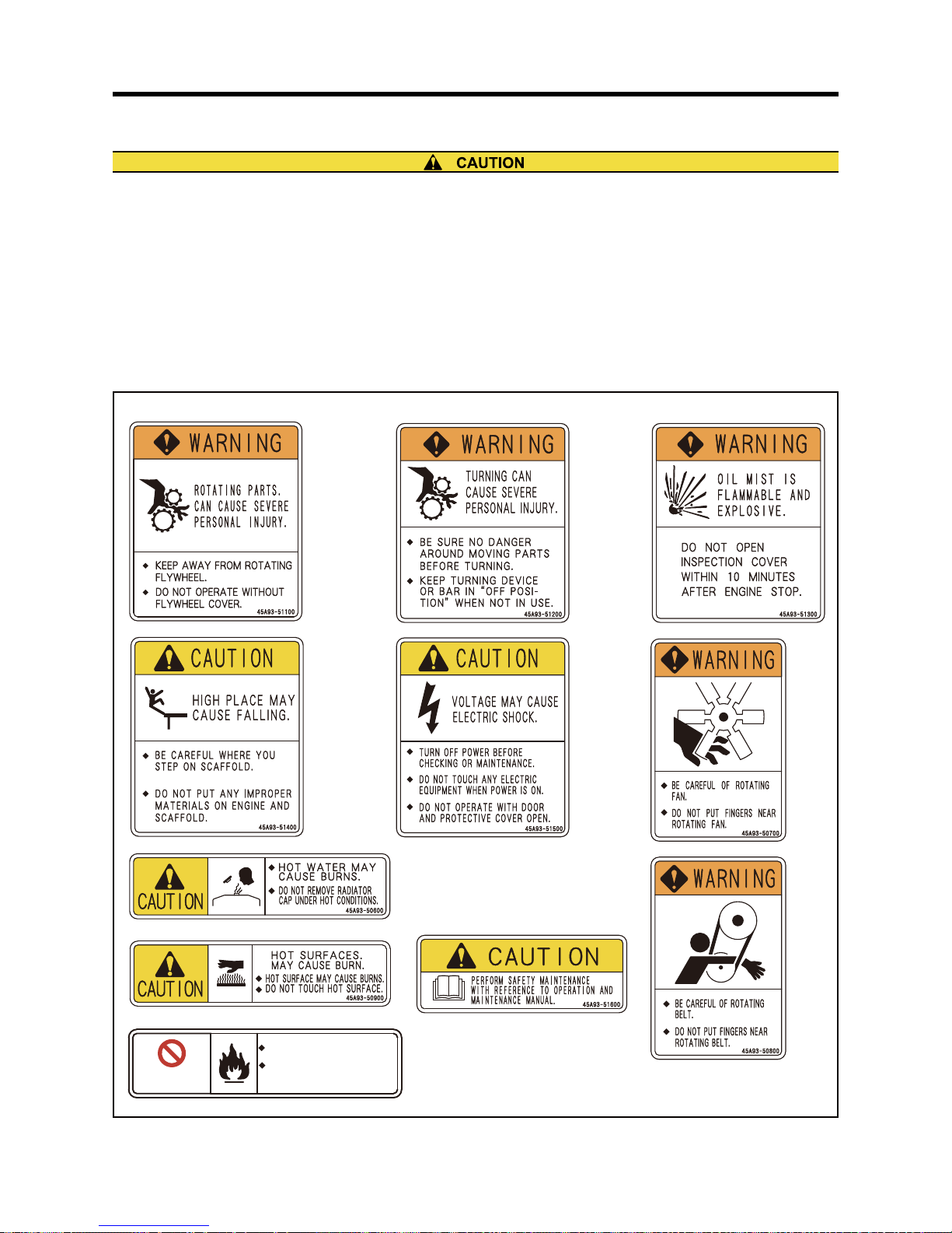
Warning Labels
Maintenance of Warning Labels
Make sure all warning/caution labels are legible.
Clean or replace the warning/caution labels when the description and/or illustration are not clear to read.
For cleaning the warning/caution labels, use a cloth, water and soap. Do not use cleaning solvents, gasoline or
other chemicals to prevent the letters from getting blurred or the adhesion from being weakened.
Replace damaged or fractured labels with new ones.
If any engine part on which a warning label is attached is replaced with a new one, attach a new identical warning
label to the new part.
To obtain new warning labels, contact your local dealer.
Fig. 1-1 Warning Labels
6*'4'+5('#41(#(+4'
6 * ' 4 ' + 5 ( ' # 4 1 ( # ( + 4 '
#
#
241*+$+6+10
241*+$+6+10
2.'#5'&1016$4+0)
2 . ' # 5 ' & 1 0 1 6 $ 4 + 0 )
(+4'%.15'
( + 4 ' % . 1 5 '
Page 26

Page 27
2-1
Chapter 2 NAME OF PARTS
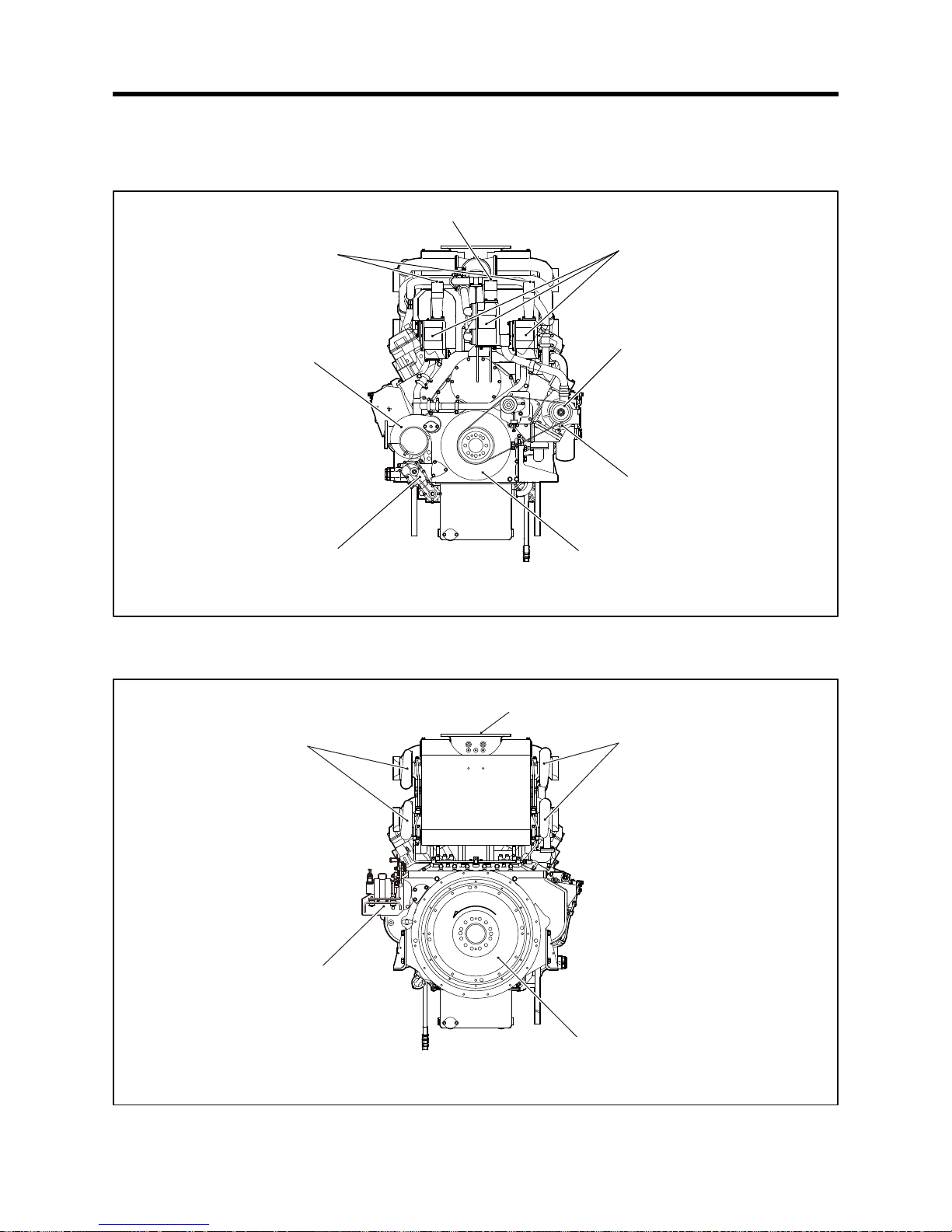
Engine External Views
Front View
Fig. 2-1 Engine Front View
Rear View
Fig. 2-2 Engine Rear View
Aircooler coolant outlet
Thermostat
Aircooler water pump
Aircooler water pump
coolant drain cock
Oil pump
Engine water pump
Engine coolant outlet
Damper
Governor actuator
Turbocharger
Turbocharger
Exhaust gas outlet
Flywheel
O
I
T
A
O
R
N
T
Page 28
2-2
Chapter 2 NAME OF PARTS
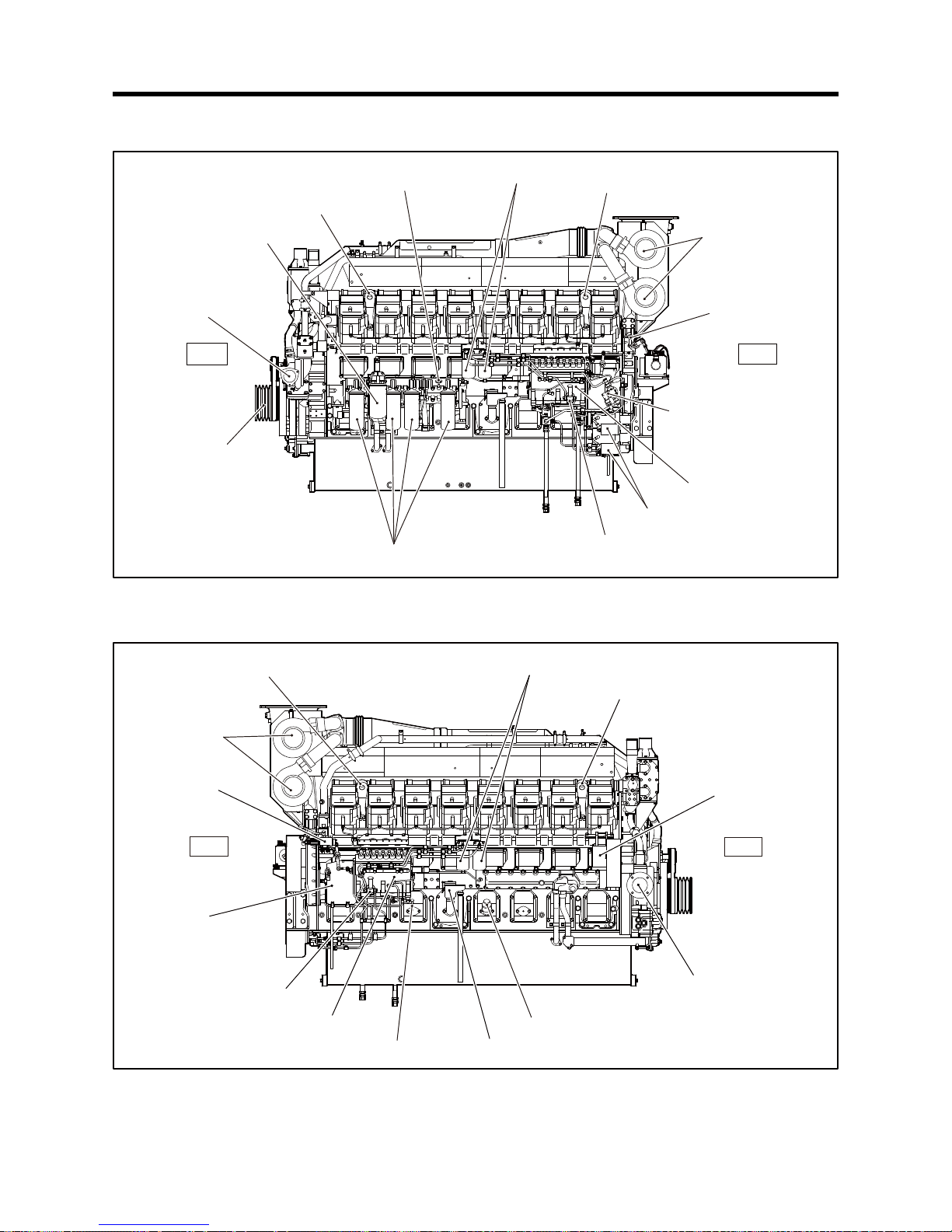
Left View
Fig. 2-3 Engine Left View
Right View
Fig. 2-4 Engine Right View
Rear
Starter
Front hanger
Oil filter alarm switch
Fuel filter
Aircooler
coolant inlet
Front accessory
drive
Bypass oil filter
Oil filter
Rear hanger
Intake air inlet
Manual stop lever
Fuel feed pump
Engine coolant
drain cock
(Behind of coupling cover)
Fuel injection pump
Front
Rear hanger
Fuel filter
Front hanger
Alternator
Engine coolantinlet
Breather
Fuel injection pump
Fuel feed pump
Engine coolant
drain cock
(Behind of coupling cover)
Stop solenoid
Intake air inlet
Rear
Front
Oil filler
Oil level gauge
Page 29
2-3
Chapter 2 NAME OF PARTS
Equipment and Instrument
The installed equipment and shapes vary with specifications.
Start and Stop Instrument
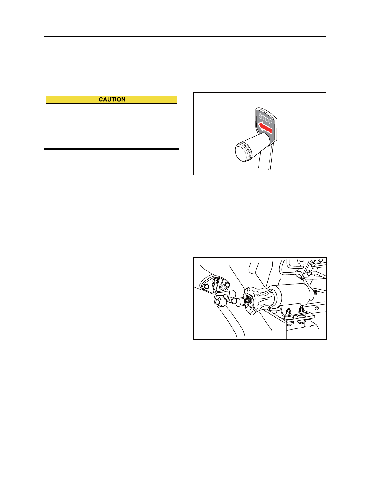
Manual Stop Lever
A manual stop lever is equipped so that you can stop
the engine in the event of an emergency and also for
the use when the engine will not stop by the stop but-
ton.
You can stop the engine by moving the manual stop
lever, which is located in the fuel control link, in the
"STOP" direction.
If the engine continues to run even after the manual
stop lever is moved to the "STOP" position, cut off the
fuel supply to the engine.
Fig. 2-5 Manual Stop Lever
Stop Solenoid
The stop solenoid is used for normal shutdown of
engine operation.
The stop solenoid moves the rack of fuel injection
pump to cut the fuel so that the engine stops.
The RUN ON type stop solenoid is equipped in this
engine. The stop solenoid is energized while the
engine is running. To stop the engine, it is de-ener-
gized by breaking contact between governor power
and electrical circuit.
Fig. 2-6 Stop Solenoid
When stopping the engine with manual stop lever,
keep the manual stop lever at the stop position until
the engine completely stops. If you release the lever
before the engine completely stops, the engine may
restart.
STOP
Page 30
2-4
Chapter 2 NAME OF PARTS
Transmitters to Instruments
This section describes about devices which transmit signals to instruments for operation. Read carefully and under-
stand functions of each device.
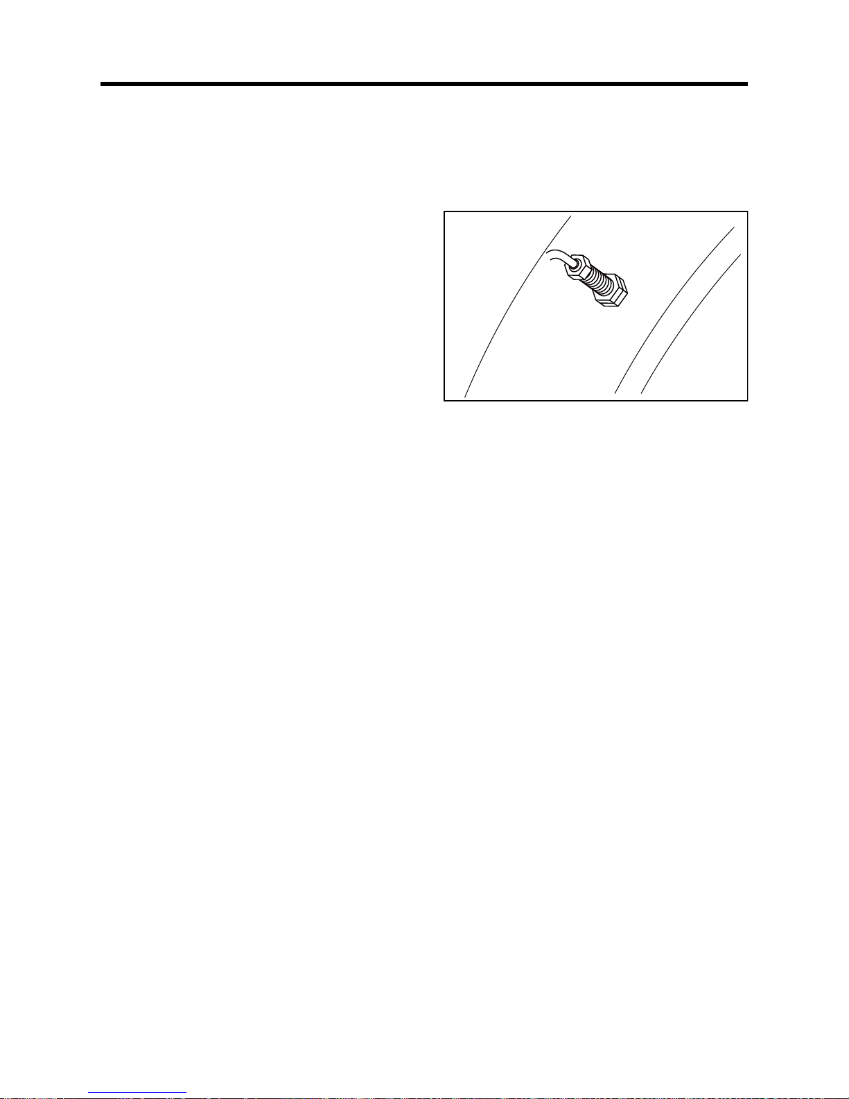
Revolution Detection Pickup
Located on the timing gear case, and detects engine
speed at all times.
Fig. 2-7 Revolution Detection Pickup
Page 31

2-5
Chapter 2 NAME OF PARTS
Engine Protection Devices
The engine protection devices activate an alarm when an abnormality occurs in the engine in order to protect the
engine and prevent serious problems and accidents. When a protection device is activated, stop the engine, exam-
ine the cause of the abnormality, and take corrective measures. If you cannot find the cause of the problem, contact
your local dealer. Protection devices installed on the engine and their types (setting values) and shapes vary
depending on the engine specifications.
Thermo Switch
The oil pressure switch generates an alarm when the
engine coolant temperature becomes high and
reaches the specified temperature.
Fig. 2-8 Thermo Switch
Oil Filter Differential Pressure Alarm Switch
The oil filter alarm switch generates an alarm to stop
the engine when the difference in pressure across the
filter reaches the specified lever due to filter clogging.
Fig. 2-9 Oil Filter Differential Pressure Alarm Switch
Air Cleaner Indicator
If the element is clogged, the intake air is decreased
and the red signal mark will be displayed. The signal
indicates only, and does not generate an alarm,
Therefore, the periodic visually inspection is needed.
Press the reset button on the top of air cleaner indica-
tor and restore the signal after cleaned the air cleaner
indicator or replaced with a new one.
Fig. 2-10 Air Cleaner Indicator
Thermo switch
Oil filter alarm switch
Reset button
Signal
(red)
Page 32

2-6
Chapter 2 NAME OF PARTS
Using Manual Turning Gear
1. Loosen two bolts, and remove the plate from the
shaft groove.
Fig. 2-11 Manual Turning Gear Position
(While Engine is Running)
2. Push the shaft fully to engage it with the ring gear.
Fig. 2-12 Manual Turning Gear Position
(When Pushing Shaft in)
3. Using a socket wrench and a ratchet handle, turn
the shaft.
4. After turning, pull out the shaft, insert the plate in
the shaft groove, and tighten the bolts.
Fig. 2-13 Manual Turning Gear Position
(When Turning Shaft)
Before starting the engine, make sure that the turning gear is pulled out in the original position. Starting the engine
with the turning gear pushed in not only damages the ring gear but also may result in personal injury.
Bolt
Bolt
Plate
Shaft
Make sure the plate is securely installed in the shaft
groove.
Socket
Ratchet handle
Page 33

3-1
Chapter 3 OPERATION
Operational Environment
Preparation for Operating New or Overhauled Engine
Before proceeding with operation of a new or overhauled engine, conduct the inspections described in this section.
For second operation onward, follow the instructions described in the "Normal Engine Operation" (3-10)
Preparation of Fuel System
1. Make sure the inside of the fuel tank and the fuel supply pipes to the engine are thoroughly clean.
2. Close the fuel tank drain valve.
3. Fill fuel tank with fuel.
4. Remove the fuel feed pipe, and check the discharged fuel for foreign materials such as dust.
5. Install the fuel supply pipe to the engine fuel inlet port.
6. After the contact of the float switch is checked, add fuel to "FULL" level.
Check that the following contents are performed before the engine is operated. Failure to do so may cause various
problems and will shorten the service life of the engine.
Prevent from spreading water (especially, seawater or rainwater) and entering foreign materials to the air inlet
opening.
Prevent from entering foreign materials to the rotating parts.
Prevent from attaching water and dust to the electrical system.
Use the engine at 5 to 40 °C [41 to 104 °F].
Keep the coolant temperature properly by switching ON the water heater (automatic mode). (Emergency generator
with water heater)
When handling fuel, make sure there are no open flames or other fire hazards near the engine.
Wipe off any spilled fuel completely. Spilled fuel can ignite and cause a fire.
Do not remove the strainer during fuel tank filling.
For fuel to be used, refer to "FUEL" (4-1)
Page 34

3-2
Chapter 3 OPERATION
Fuel System - Bleed Air
When bleeding the fuel system, start with the compo-
nent closest to the fuel tank, that is, from the oil-water
separator to fuel filter to fuel injection pump.
Bleeding air from the oil-water separator differs
depending on fuel piping. Bleed air in an appropriate
way.
Bleed air from fuel filter or fuel injection pump using
priming pump.
Fig. 3-1 Priming Pump - Operate
Fuel Filter - Bleed Air
1. Loosen the air vent plug of the fuel filter about 1.5
turns.
2. Move the priming pump up and down to feed fuel.
3. When the fuel from the air vent plug becomes free
from air bubbles, stop priming and tighten the air
vent plug to the specified torque.
Fig. 3-2 Fuel Filter - Bleed Air
Fuel Injection Pump - Bleed Air
1. Loosen the air vent plug on the fuel injection pump
by rotating about 1.5 turns.
2. Move the priming pump up and down. When the
fuel flow from the air vent plug becomes free of
bubbles, turn the priming pump clockwise while
pushing it to lock.
3. Tighten the air vent plug on the fuel injection pump.
Fig. 3-3 Fuel Injection Pump - Bleed Air
When fuel overflows from the air vent plug, wipe
thoroughly with a cloth. Spilled fuel can cause a fire.
After air bleeding, lock the priming pump securely. If
the cap is not locked tightly, the priming pump can be
damaged, causing a fuel leak that could lead to a
fire.
[Unlock] [Prime] [Lock]
Turn counterclockwise
Move cap up
and down
Turn clockwise
while pressing
If air vent plugs, the thread portion of the bracket, or
sealing washers are damaged, replace them with
new ones.
Air vent plug
Tightening torque
8.8 ± 1 N·m
{0.9 ± 0.1 kgf·m}
[6.4 ± 0.7 lbf·ft]
Air vent plug
15 ± 2 N·m
{1.53 ± 0.20 kgf·m}
[11.06 ± 1.48 lbf·ft]
Page 35

3-3
Chapter 3 OPERATION
Priming Pump Tightening Method
1. Gently tighten the priming pump by hand, and
make a mark indicating the seating position.
2. Using a wrench or another appropriate tool, further
tighten the priming pump by 90±10°.
3. Check the mounting position of head packing.
Note: If the head packing has abnormality such as de-
formation or scratches, the priming pump should
be replaced. Consult a dealer of Mitsubishi
Heavy Industries, Ltd. for replacement of the
priming pump.
Fig. 3-4 Priming Pump Tightening Method
Fig. 3-5 Priming Pump Head Packing
Never fail to tighten the priming pump to the speci-
fied angle. If the priming pump is not firmly tightened,
internal thread will be worn due to engine vibration,
resulting in sudden ejection of the cap to cause fuel
flow-out. Or if the priming pump is excessively tight-
ened, the head of the priming pump can be dam-
aged.
Position where
the sheet has
been seated.
Head section can be
damaged when
overtightened
90 ±10°
Head packing
Page 36

3-4
Chapter 3 OPERATION
Preparation of Lubrication System
Engine Oil - Filling
1. Remove the oil filler cap.
2. Add the specified engine oil to the specified level.
Note: For engine oil, refer to "ENGINE OIL" (5-1). For
engine oil capacity, refer to "MAIN SPECIFICA-
TIONS" (12-1).
3. Remove the rocker cover of every cylinder, and
pour engine oil to the valve mechanism and cam-
shaft oil bath.Pour engine oil to the camshaft oil
bath from cylinder head side.
Oil capacity per cylinder: 0.8 L [0.21 U.S. gal.]
4. Reinstall the rocker covers.
5. Check the oil level in oil pan as follows:
6. Pull out the oil level gauge and wipe it clean with a
cloth.
7. Insert the oil level gauge fully into the oil level
gauge guide and then pull it out again.
8. The oil level should be between the maximum and
minimum marks on the oil level gauge.If the oil lev-
el is low, add the specified engine oil.
9. Check the oil pan, etc., for oil leaks.Repair if there
is oil leak.
10. With the stop knob placed in pulled position, rotate
the engine with starter for approx. 10 seconds to
circulate oil to the whole engine. Stop the rotation
for 1 minute, then, repeat the rotation two or three
times to circulate the engine oil to each engine
parts.
Note: Also perform the Preparation of Cooling System
described below.
11. Start the engine and run at a no-load and low-idling
condition for 5 to 10 minutes.
12. Stop the engine, and after 30 minutes or more has
elapsed, check the oil level with the oil level gauge
again and add oil to the specified level.
For details, refer to"Test Operation" (3-9).
Fig. 3-6 Oil Filler and Oil Level Gauge
Fig. 3-7 Pouring Engine Oil on Valve Mechanisms and
Chamber
Refill the engine with the specified engine oil to the
specified level.If the oil level is higher than the maxi-
mum mark on the level gauge, engine oil may blow
out during operation.Also, the increase of oil temper-
ature could adversely affect engine components.
H
L
Oil filler
Oil level gauge
Oil level gauge
High
Low
Improper
Improper
Proper
Camshaft
oil bath
Page 37

3-5
Chapter 3 OPERATION
Preparation for Cooling System
Coolant - Refill (Engine)
Note: If the specification of radiator differs from the
contents of this operation manual, follow the
manufacturer's operation manual.
1. Make sure coolant drain cocks are closed securely.
2. Remove the radiator cap, and add a mixture of wa-
ter and LLC of the specified concentration to the
specified level.
Note: (a) Determine the quantities of LLC based on the
coolant capacity and the LLC concentration
chart.
For the coolant, refer to "COOLANT" (6-1).
For the coolant capacity, refer to "MAIN
SPECIFICATIONS" (12-1).
(b) For absolute air bleeding, loosen the air vent
plug.
3. Check the radiator and other parts for coolant
leaks. Repair leakage if found.
4. When coolant reaches the specified level, close the
radiator cap securely.
5. With the manual stop lever placed in the pulled po-
sition, crank the engine for approx 10 seconds us-
ing the starter. Stop cranking for 1 minute, then,
repeat the cranking two or three times to bleed the
cooling system.
Note: Prepare for the lubricating system and refilling
the coolant to the Air Cooler.
6. Check the coolant level in the radiator.
Fig. 3-8 Coolant Drain Cock (Engine)
Fig. 3-9 Coolant Drain Cock
(Engine water pump)
Fig. 3-10 Air Vent Plug (Engine Cooling System)
When adding coolant, use the same LLC concentra-
tion coolant that is currently in the cooling system.
Coolant
drain cocks
Left side
Right side
The coolant drain cocks located in the crankcase
(behind the each fuel injection pump
accessory drive unit respectively).
Coolant
drain cock
Air vent plug
Page 38

3-6
Chapter 3 OPERATION
Coolant - Refill (Air Cooler)
Note: If the specification of radiator differs from the
contents of this operation manual, follow the
manufacturer's operation manual.
1. Make sure coolant drain cocks are closed securely.
2. Remove the radiator and add a mixture of water
and coolant having the specified concentration.
Note: (a) Determine the quantities of LLC based on the
coolant capacity and the LLC concentration
chart.
For the coolant, refer to "COOLANT" (6-1).
For the coolant capacity, refer to "MAIN
SPECIFICATIONS" (12-1).
(b) For absolute air bleeding, loosen the air vent
plug.
3. Check the radiator and other parts for coolant
leaks. Repair leakage if found.
4. When coolant reaches the full level, close the cool-
ant filler securely.
5. While pulling the manual stop lever, crank the en-
gine for approx 10 seconds using the starter. Stop
the operation for 1 minute, then, repeat the opera-
tion two or three times to bleed the cooling system.
Note: Prepare for the lubricating system and refilling
the coolant to the engine.
6. Check the coolant level in the radiator.
Fig. 3-11 Coolant Drain Cock (Air Cooler)
Fig. 3-12 Coolant Drain Cock
(Air Cooler water pump)
Always use the coolant having the same concentra-
tion.
Coolant drain cock
Air vent plug
Air vent cocks
Page 39

3-7
Chapter 3 OPERATION
Preparation of Electrical System
Battery - Check
Note: If the specification of battery differs from those of this operation manual, follow the manufacturer's operation
manual.
Battery Electrolyte Level - Inspect
The battery electrolyte evaporates in the use, and the
electrolyte level gradually decreases. The proper elec-
trolyte level is between the LOWER LEVEL and
UPPER LEVEL marks.
For the battery without level marks, the proper electro-
lyte surface level is about 10 to 15 mm [0.39 to 0.59
in.] above the top of the polar plates.
If the electrolyte level is low, remove the caps and add
distilled water to the proper level.
Note: When adding distilled water, add little by little.
Fig. 3-13 Battery Electrolyte Level - Inspect
Never use flames or allow sparks near the battery. The battery releases flammable hydrogen gas and oxygen gas.
Any flames or sparks in the vicinity could cause an explosion.
Do not use the battery when the battery electrolyte level is below the "LOWER LEVEL" mark. Continual use may
result in an explosion.
Do not short the battery terminals with a tool or other metal object.
When removing battery, always remove the plug from the negative (-) terminal first. When connecting battery,
always connect the plug to the positive (+) terminal first.
Remove all battery cables, then charge the battery in a well ventilated area.
Make sure the cable clamps are securely installed on the battery terminals. A loose cable clamp can cause sparks
that may result in an explosion.
Before servicing electrical components or conducting electric welding, set the battery switch to [Open/OFF] posi-
tion or remove the plug from the negative (-) terminal to cut off the electrical current.
Electrolyte (battery electrolyte) contains dilute sulfuric acid.Careless handling of the battery can lead to loss of
sight and/or skin burns. Also, do not swallow the battery electrolyte.
Wear protective goggles and rubber gloves when working with the battery (e.g. when adding water or charging
battery).
If battery electrolyte is spilled onto the skin or clothing, immediately wash it away with lots of water. Use soap to
thoroughly clean.
The battery electrolyte can cause blindness if splashing into the eyes.If it gets into your eyes, immediately flush it
away with plenty of clean water, and seek immediate medical attention.
If you accidentally swallow battery electrolyte, gargle with plenty of water and then drink lots of water, and seek
immediate medical attention.
If the battery does not fully recover after 24 hours charging or more, do not use the battery.
UPPER LEVEL
LOWER LEVEL
10 to 15 mm
[0.39 to 0.59 in.]
Proper
Page 40

3-8
Chapter 3 OPERATION
Specific Gravity of Battery Electrolyte - Check
If the specific gravity measured at 20°C [68°F] is lower
than 1.22, charge the battery.
Fig. 3-14 Specific Gravity of Battery Electrolyte -
Check
Table 3-1 Specific Gravity of Electrolyte
Specific gravity
at 20°C [68°F]
Conditions Remedy
From 1.26 to 1.28 Fully charged -
From 1.22 to 1.26
Partially
charged
Charge
Less than 1.22 Discharged Charge
Float
Electrolyte
surface
Electrolyte
Glass tube
Page 41

3-9
Chapter 3 OPERATION
Test Operation
To conduct a test operation, follow the procedures below.
Before starting the engine, switch the water heater ON (automatic mode) and keep the coolant temperature prop-
erly.(Emergency generator with water heater)
Note: For engine operation, refer to "Normal Engine Operation" (3-10).
Starting and Stopping
1. Start the engine.
2. Operate the engine at a low idling speed under no load for 5 to 10 minutes for warm-up.
3. Stop the engine.
Inspection
1. Leave the engine be stopped for about 30 minutes.
2. During this period, check the engine and surrounding area for leaks of fuel, engine oil or coolant.
3. At 30 minutes after the engine stop, check the oil level with the oil level gauge.
4. If the oil level is low, add engine oil from the oil filler. Be sure to use the engine oil of the same brand and type.
5. Open the radiator cap and check the coolant level.
6. If the coolant level is low, add coolant to the specified level.
If the engine is equipped with a reserve tank, fill the reserve tank with coolant to the "FULL" level line as well.
Always switch the water heater ON (automatic mode) through a whole year.
If the switch is not ON (automatic mode), each cylinder varies considerably in combustion and abundant white
exhaust gas generates at the starting up the engine. Unburned fuel may explode in the exhaust pipe. (Emergency
generator with water heater)
Never open the radiator cap while the engine is running or immediately after the generator set is stopped. Stop the
engine and open the cap after the coolant temperature lowers sufficiently.
Place a waste cloth over the radiator cap, and loosen the cap about a 1/4 turn or stand the lever to the upright
position to release internal pressure.
The coolant is hot while engine is running and immediately after the engine stops. If the cap is opened when the
coolant is at operating temperature, steam and hot coolant may blow out and result in burns. To avoid a risk of get-
ting scalded by steam, wear thick rubber gloves or wrap a cloth around the cap.
When closing the radiator cap, be sure to tighten securely.
Always use the coolant having the same concentration.
Page 42

3-10
Chapter 3 OPERATION
Normal Engine Operation
This section of the manual covers the procedures for the engine operation in normal condition.
Preparations for Operation
Always conduct daily pre-start inspection before starting the engine for the day.
Engine External - Inspect
Inspect the engine exterior as instructed below.
1. Make sure there is no combustible material near the engine or battery. Also, check to make sure that the engine
and battery are clean. If combustible materials or dust are found near the engine or battery, remove them.
2. Check the electrical wiring for components such as the starter and alternator for looseness.
3. Make sure that the turning tool is pulled out in it's original position.
4. Make sure fluids, such as fuel, oil and coolant, are not leaking from the engine. If a leak is found, repair the leak,
or contact your local dealer.
5. Make sure the following valves, plugs or cocks are properly positioned.
Fuel feed valve: Open
Coolant drain cock (plug): Closed
Engine oil drain valve: Closed
Fuel Tank Oil Level - Check
Make sure that the fuel tank is filled to the specified level.
If the fuel level is low, add fuel to the "FULL" level.
Note: If the specification of fuel tank differs from the contents of this operation manual, follow the fuel tank manufac-
turer's operation manual.
If the engine abnormality is observed during operation, stop the engine and correct the problem, or contact your
local dealer.
Check external parts of the engine, particularly hot part (exhaust manifold, etc.) and battery unit for any accumula-
tion of flammables, fuel leaks, and engine oil leaks, etc. Remove dust from the top surface of the battery. If some-
thing goes wrong with the hot parts, it may cause a fire. If any abnormality is found, be sure to repair it or contact
your local dealer.
When handling fuel, make sure there are no open flames, heaters or other fire hazards.
Wipe off any spilled fuel completely. Spilled fuel can ignite and cause a fire.
Do not remove the strainer during fuel tank filling.
If fuel level is above the low alarm mark where float switch is equipped, the float switch may be broken. Check and
correct the problem.
For fuel to be used, refer to "FUEL" (4-1).
Page 43

3-11
Chapter 3 OPERATION
Fuel Tank - Drain Water
If fuel gets mixed with particles of foreign material
such as dust, dirt, or water, it can cause not only
decrease of output but also malfunctions of the fuel
system. To avoid such a problem, drain fuel tank as
described below.
Note: If the specification of fuel tank differs from the
contents of this operation manual, follow the fuel
tank manufacturer's operation manual.
1. Place the oil pan (capacity of 2 liters [0.5 US gal] or
more) under the drain cock of fuel tank.
2. Open the drain cock of fuel tank and drain fuel at
least 1 to 2 liters [0.3 to 0.5 US gal].
3. After checking that there is no water or foreign ob-
ject in the drained fuel, close the drain cock.
Fig. 3-15 Fuel Tank - Drain Water
Fuel Control Link - Check
Check fuel control link for smooth movement.
Push the manual stop lever to the fuel increase direc-
tion, check the movement of the rack cancel spring.
Then loosen your grip on the lever little by little, mak-
ing sure the manual stop lever returns to the no fuel
injection position smoothly.
Also check all ball joints for looseness and play.
Fig. 3-16 Check Fuel Control Link
When handling fuel, make sure there are no open flames, heaters or other fire hazards. Wipe off any spilled fuel
completely. Spilled fuel can ignite and cause a fire.
Do not remove the strainer when filling the fuel. For fuel to be used, refer to "FUEL" (4-1).
The following is a common procedure to drain water from fuel tanks, although the fuel tank actually installed may
exactly the same.
Drain cock
Water
Rack cancel spring
Manual stop lever
Ball joint
Page 44

3-12
Chapter 3 OPERATION
Engine Oil Level - Check
1. Stop the engine and leave it for 30 minutes or
more.
2. Pull out the oil level gauge and wipe oil off the oil
level gauge using a clean waste cloth.
3. Insert the oil level gauge fully into the oil level
gauge guide and then pull it out again.
4. The proper oil level is between the high and low
marks on the oil level gauge. If the engine oil level
is higher than the high mark on the oil level gauge,
drain the oil. If the oil level is low, add the specified
engine oil.
5. Install the oil filler cap after engine oil has been re-
filled.
6. Check the oil pan and other area for oil leaks.
Fig. 3-17 Oil Filler and Oil Level Gauge
Coolant Level - Check
If the coolant level is low, add coolant to the specified level.
Note: Determine the quantities of LLC based on the coolant capacity and the LLC concentration chart.
For the coolant, refer to "COOLANT" (6-1). For the coolant capacity, refer to "MAIN SPECIFICATIONS" (12-1).
Always add engine oil to the specified level. If the oil
level is higher than the maximum mark on the level
gauge, engine oil may blow out during operation.
Also, the increase of oil temperature may adversely
affect engine components.
When adding engine oil, always use the same
engine oil.
H
L
Oil filler
Oil level gauge
Oil level gauge
High
Low
Improper
Improper
Proper
When adding coolant, use the same LLC concentration coolant that is currently in the cooling system.
Page 45

3-13
Chapter 3 OPERATION
Air Cleaner - Check for Clogging
1. Check the air cleaner indicator for the element
clogging.
2. If the element is clogged, the red signal mark will
be displayed.
3. Immediately clean or replace the air cleaner ele-
ment when the signal turns red.
4. After checking, press the bottom on top of the indi-
cator to re-set the alarm signal.
Note: (a) For cleaning of the air cleaner element, refer
to "Air Cleaner Element - Clean, Check and
Replace" (8-22).
(b) If the specification of air cleaner differs from
the contents of this operation manual, follow
the manufacturer's operation manual.
Fig. 3-18 Air Cleaner - Check for Clogging
Temperature of Damper - Check
Damper Temperature Control by Thermo Label
Use of thermo label is recommenced for damper tem-
perature control. Check the thermo label before start-
ing engine as instructed below.
1. Ensure the heat-sensitive part of thermo label is
black.
2. Record the highest temperature of heat-sensitive
part. Record the temperature periodically, by which
you can check the abnormality of temperature al-
teration.
Note: For damper temperature limit and damper in-
spection, refer to "Damper - Inspect" (8-5).
Fig. 3-19 Thermo Label of Damper
Reset button
Signal
(red)
If the abnormality of temperature alteration is found,
consult a dealer of Mitsubishi Heavy Industries, Ltd.
75 80 85 90 95
100 105 110 115 120
50 55 60 65 70
Thermo label
ࠨࡕࡌ࡞
ࠨࡕࡌ࡞
ࠨࡕࡌ࡞
5E-75
5E-100
5E-50
5E-75
5E-100
5E-50
5E-75
5E-100
5E-50
5E-75
5E-100
5E-50
(Display example)
When thermal part of the thermo label is
black until 80, it indicates that the maximum
temperature of damper during operating is
from 80°C [176°F] to 85°C [185°F].
Page 46

3-14
Chapter 3 OPERATION
Starting-up
Warm-up Operation
Warm-up the engine at low idle speed until the coolant temperature reaches approx. 50°C [122°F].
Engine Oil Pressure - Check
During warm-up operation, check if the oil pressure is in the range of standard value (0.3 MPa {3.1 kgf/cm2} [21 psi]
or more).
Also, make sure the oil pressure gauge functions properly.
External Inspection During Warm-up
Visually inspect the engine for external damage, abnormal noise, odor, vibration and exhaust gas color, then inspect
for fuel, engine oil and coolant or exhaust gas leaks from joints during warm-up operation.
Before starting the engine, make sure no one is near the engine and that tools are not left on or near the engine. In
a loud voice, notify people in the area when starting the engine.
Do not apply load to the engine when starting.
Continuous operation of the starter will drain the battery power or cause the starter to seize. Do not use the starter
for more than 10 seconds at a time. When the engine does not start, wait for more than 1 minute before cranking
again.
Stay away from rotating parts during operation. If you are caught in rotating parts, you can be seriously injured or
killed.
Page 47

3-15
Chapter 3 OPERATION
Operation
Cautions During Operation
Inspection During Operation
Carefully check the exterior of engine such as piping
joints for leaks during operation.
Check engine for abnormal noise, odor or vibration
during warmimg-up operation.
Check the exhaust gas color from the exhaust muffler.
Check the instruments and gauges for proper opera-
tion and make sure they indicates normal values.
Note: (a) When the oil pressure drops below 0.29 MPa
{3 kgf/cm
2
} [42.7 psi] in normal operation, or
below 0.1 MPa {1 kgf/cm
2
} [14.2 psi] at low
idling, stop the engine immediately.
Be sure to locate the cause of problem and
correct it before restarting the engine.
(b) When the thermo switch is activated during
normal operation, run the engine with the idle
speed at low Rpm for 5 or 6 minutes to cool
the engine before stopping the engine. Be
sure to locate the cause of problem and cor-
rect it before restarting the engine.
Stay away from rotating parts during operation.
Entanglement in rotating parts can cause serious
injury.
Do not touch any hot part of the engine such as
exhaust pipes during operation or immediately after
shut down. You may get burned.
Always provide adequate ventilation in the engine
room. If air ventilation in the engine room is not suffi-
cient, the room temperature rises and can affect
engine output and performance.
For the first 50 hours of a new or overhauled engine,
operate the engine under a light load for break-in
operation. Do not operate the new engine under
heavy load or severe conditions during the break-in
period, as it will shorten the service life of the engine.
Do not turn the battery switch OFF during operation.If
the battery switch is turned off during operation, it will
not only stops various functions of instruments but
also may deteriorate the alternator diode and transis-
tor.
Never turn the key to the "START" position during
operation. It may cause damage to the starter.
When operating the engine with a 30 % of rated load
or lower, limit each operation to an hour. Prolonged
warm-up operation causes carbon accumulation in
the cylinders that leads to incomplete combustion.
Operate the engine with a 30 % of rated load or more
for over 5 minutes to prevent carbon accumulation
when one hour continuous operation has been con-
ducted.
Pay attention to the generated voltage of generator
set.
Table 3-2 Standard values at rated speed
Item Standard
Engine oil pressure
0.49 to 0.64 MPa
{5 to 6.5 kgf/cm
2
}
[71 to 92 psi]
Coolant
temperature
Basic engine
cooling system
70 to 90°C
[158 to 194°F]
Air Cooler
cooling system
40 to 70°C
[104 to 158°F]
Page 48

3-16
Chapter 3 OPERATION
Stopping
Engine stopping method varies depending on the specifications.
To stop the engine, follow the proper instructions for each machine.
Emergency Stop
To perform an emergency stop, pull the manual stop
lever fully to the stop direction (arrow). Keep pulling
the manual lever until the engine stops completely.
Note: When the engine does not stop even if the man-
ual stop lever is pulled, cut fuel supply.
Fig. 3-20 Manual Stop Lever
Inspection After Stopping
Inspect the engine for fluid leaks such as fuel, oil or coolant. If any leak is found, repair the leak or contact a your
local dealer.
Stopping the engine abruptly during high-speed operation or while engine is hot will shorten the engine life. Before
stopping the engine, run the engine with the idle speed at low Rpm for 5 or 6 minutes to cool the engine, and
check the engine for abnormalities.
Do not race the engine immediately before shutting it down.
If the engine stops abnormally, do not restart the engine immediately. When the engine stops with alarms, be sure
to locate the cause of the problem and correct the problem before starting the engine again. After restarting the
operation, check the engine for abnormalities again. If an abnormality is detected, repair it immediately.
When stopping the engine by pulling the manual
stop lever, keep pulling the lever until the engine
stops completely. If not, the engine may start again.
STOP
Page 49

4-1
Chapter 4 FUEL
Recommended Fuel
Use fuel that meets the values specified in the following "Recommended Fuel" (4-1) and "Recommended Limit and
Use Limit of Fuel Property" (4-2)
It is necessary to use fuel that has a pour point suitable for the ambient temperature.
Note: Please use the fuel that meets the regulations of the countries or areas where the engine is used, if the regu-
lations are applied.
Handling Fuel
When using fuel that is stored in a storage tank, leave it for more than 24 hours to settle dust and water at the bot-
tom and drain them. Then, use the upper clean fuel.
Fill up the fuel tank or service tank after each operation.
This prevents water from mixing with fuel in the tank and also gives time for dust and water to separate and settle at
the bottom of the tank.
When refilling, clean the areas around the caps of drum and tank thoroughly before removing the caps. Also clean
your hands and the hose before refueling. When using a hand-operated pump, be careful not to pump water or sed-
iment accumulated at the bottom of the storage tank.
Be sure to use a strainer when filling fuel tank. For a complete filtration, it is recommended to use a clean lint-free
cloth together with the strainer.
Use the fuel specified in this manual only. And, do not refill the fuel tank more than the specified level. It could lead
a fire.
Table 4-1 Recommended Fuel
Specifications Classification
ISO 8217 DMX-CLASS
ASTM D975 No.1-D, No.2-D
BS 2869 CLASS A1, CLASS A2
DIN 51601 DIESEL-FUEL
JIS K2204 TYPE1, TYPE2, TYPE3
EN 590 DIESEL-FUEL
Page 50

4-2
Chapter 4 FUEL
Fuel Specification
Use fuel which meets the requirements specified in the table below.
Table 4-2 Recommended Limit and Use Limit of Fuel Property
Item Recommended limit Use limit Test method
Flash point
50°C [122°F] or higher
(In accordance with the regulation)
JIS K 2265
:2007
ISO 3769
ISO 2719
Distillation
Initial boiling point 170°C [338°F] or higher
JIS K 2254
:1998
ISO 3405
90 % distillate
temperature
330 to 380°C [626 to 716°F]
Pour point (PP) Lower than ambient temperature by 6°C [43°F] or more
JIS K 2269
:1987
ISO 3016
Cloud point (CP) Below ambient temperature
JIS K 2269
:1987
ISO 3015
Cold filter plugging point (CFPP) Lower than ambient temperature by 3°C [37°F] or more
JIS K 2288
:2000
IP 309/96
Carbon residue (10 % residual oil) 0.4 weight % or lower 1.0 weight % or lower
JIS K 2270
:2000
ISO 6615
ISO 10370
Cetane number 45 or higher
JIS K 2280
:1996
ISO 5165
Cetane index (new type) 45 or higher
JIS K 2280
:1996
ISO/DIS 4264
Kinetic viscosity
2.0 mm
2
/s [0.0031 in2/s] or more at 30°C [86°F]
8.0 mm
2
/s [0.0124 in2/s] or more at 30°C [86°F]
JIS K 2283
:2000
ISO 3104
Sulfur content 0.2 weight % or lower
1.0 weight % or lower
(Shorten lub. oil change
intervals)
JIS K 2541
:2000
(The content
should be as
low as the diesel fuel.)
ISO 4260
ISO 8754
Water content and sediment 0.1 volume % or lower
JIS K 2275
:1996
ISO 3733
Ash content 0.01 weight % or lower 0.03 weight % or lower
JIS K 2272
:1998
ISO 6245
Copper corrosion
(3 hrs at 50°C [122°F])
Discoloration = Copper plate No.3 or less
JIS K 2513
:2000
ISO 2160
Density at 15°C [59°F]
0.83 to 0.87 g/cm
3
[49.9424 to 54.3123 lb/ft
3
]
0.80 to 0.87 g/cm
3
[49.9424 to 54.3123 lb/ft
3
]
JIS K 2249
:1995
ISO 3675
Caulking
24 hrs at 250°C
[482°F]
75 % carbonization or less 80 % carbonization or less
Fed 791B
24 hrs at 230°C
[356°F]
55 % carbonization or less -
48 hrs at 180°C
[356°F]
Ta r- f re e -
Aromatics substances (by HPLC) 38 % by volume or less
JIS K 2536
:2003
ISO 3837
Polycyclic aromatic content 8 volume % or lower
Asphaltene 0.1 weight % or lower -
Page 51

4-3
Chapter 4 FUEL
Foreign substances
(foreign materials at engine fuel
inlet)
5.0 mg/liter or less
JIS B 9931
:2000
ISO 4405
Lubricity: MWSD (Measured mean
Wear Scar Diameter) by HFRR
wear test at 60°C [140°F] fuel
temperature
460 μm [0.02 in.] or less
(calculated wear scar
diameter at WS 1.4 kPa
{0.0143 kgf/cm
2
}
[0.2031 psi])
- ISO 12156-1
BDF: Biodiesel fuel
(FAME: Fatty Acid Methyl Ester)
BDF quality shall meet JIS K 2390,
ASTM D 6751 or EN14214.
BDF blending of 5 % by volume or less is approved.
JIS K
2390
:2008
(Standard for
FAME)
ASTM D 6751
EN 14214
Engine applications
For engines operated under
a high load for a long period
(e.c. continuous use)
For engines operated under
a low load for a short period
of time
(e.c. stand-by use)
Selection
according to
applications
Table 4-2 Recommended Limit and Use Limit of Fuel Property
Item Recommended limit Use limit Test method
Page 52

Page 53

5-1
Chapter 5 ENGINE OIL
Recommended Engine Oil
Engine Oil Grade
Many oil standards, which are established through
special engine tests, are available to determine the
quality of oil depending on the engines to which they
will be applied and on operating conditions. Among
those standards, API (American Petroleum Institute)
service classifications are mostly used to classify
engine oils. SAE specifies the viscosity only, while the
API service classification indicates the quality level of
engine oil.
For engine lubrication oil, please use API service clas-
sification CF or CH-4.
When using the CF class engine oil, it must be certi-
fied according to API service classification CF by 2009
and satisfied the following "Table of Recommended
Limit of Engine Oil Properties" (5-2).
When using the CH-4 class engine oil, the sulfur con-
tent of fuel must be 0.2 weight % or lower.
Fig. 5-1 Engine Oil Grade
Use the engine oil recommended in this manual only. Never use oil other than that specified in this manual.
The use of inappropriate or inferior oils will result in sticking of piston rings, seizure between piston and cylinder, or
premature wear of bearings and moving parts, and significantly shortens the service life of the engine.
OILOIL
Class CH-4
API Service
Classification
API Service
Classification
Class CF
Page 54

5-2
Chapter 5 ENGINE OIL
Engine Oil Specifications
Use engine oil that meets the requirements specified in the table below.
Table 5-1 Table of Recommended Limit of Engine Oil Properties
Item Unit Recommended limit Test method
API/JASO CF class *1 -
SAE viscosity - 15W-40 -
Color ASTM - L4.0
JIS K 2580
ISO 2049
Density 15°C [59°F] g/cm
3
0.87 to 0.90
JIS K 2249
ISO 3675
ISO3838
ISO 649-4
ISO 91-1
Kinetic viscosity
40°C [104°F]
mm
2
/s
100 to 110 JIS K 2283
ISO 3107
ISO 2904
100°C [212°F] 13.5 to 15.5
Viscosity - -
JIS K 2283
ISO 3107
ISO 2904
Flash point °C [°F]
225 to 250
[437 to 482]
JIS K 2265
ISO 3679
ISO 2719
ISO 2592
Base
Number
Hydrochloric
acid method
Sulfur contents
of fuel
1.0 weight %
or lower
mgKOH/g
10 or higher
(up to 13)
JIS K 2501
ISO 3771
ISO 6618
ISO 6619
ISO 7537
0.2 weight %
or lower
8 or higher
(up to 13)
Perchloric
acid method
Sulfur contents
of fuel
1.0 weight %
or lower
mgKOH/g
13 or higher
(up to 16)
0.2 weight %
or lower
11 or higher
(up to 16)
Acid number mgKOH/g 1.5 to 2.0
JIS K 2501
ISO 3771
ISO 6618
ISO 6619
ISO 7537
Sulfur content % 0.5 or less
JIS K 2541
ISO 4260
ISO 8754
Sulfuric acid ash % 2.0 or lower
JIS K 2272
ISO 3987
ISO 6245
Carbon residue content % 2.0 or lower
JIS K 2270
ISO 10370
ISO 6615
High temperature shear viscosity 150°C [302°F] mPa•S 3.7 or higher JPI-5S-36-91
Pour point °C [°F] -25 [-13] or lower
JIS K 2269
ISO 3015
ISO 3016
Page 55

5-3
Chapter 5 ENGINE OIL
*1 API CF grade oil certified in 2009 or before.
*2 Temperature of test I (24°C [75.2°F]), Temperature of test II (93.5°C [200.3°F]), Temperature of test III (24°C
[75.2°F] after 93.5°C [200.3°F])
*3 Temperature of aluminum panel: 300°C [572°F] and 325°C [617°F], Temperature of engine oil: 100°C [212°F],
Splatter time: 15 seconds
Downtime: 45 seconds, Test time: 8 hours, the properties are the weight of solid product.
Selection of Oil Viscosity
Use the chart on the right to select the appropriate oil
viscosity according to the ambient temperature.
Excessively high oil viscosity causes power loss and
an abnormal rise of oil temperature, while excessively
low oil viscosity accelerates wear due to inadequate
lubrication, and also causes a decrease in engine out-
put.
Fig. 5-2 Selection of Oil Viscosity
Bubbling test *2
I
mL
10/0
JIS K 2518
ISO 6247
II 30/0
III 10/0
Panel caulking test *3
300°C
[572°F]
mg
140 or lower
FED791-3462
325°C
[617°F]
300 or lower
Table 5-1 Table of Recommended Limit of Engine Oil Properties
Item Unit Recommended limit Test method
SAE10W
SAE30
SAE40
SAE15W-40
Temperature
°C [°F]
Engine oil
viscosity
-30
[-21]
-20
[-4]
-10
[14]
10
[50]20[68]30[86]40[104]50[122]
0
[32]
Page 56

5-4
Chapter 5 ENGINE OIL
Handling Engine Oil
When handling a large amount of engine oil more than the legally specified quantities, be sure to have the work per-
formed by a service station operated under the provision of the law. When removing oil from the engine or oil can,
use an oil pump. Do not siphon oil using a pipe and your mouth.
Be sure to close the cap on the oil can after use.
Keep oil in a well-ventilated place and out of direct sunlight.
Be sure to obtain the MSDS of the engine oil and follow the instructions of the MSDS.
Service Limits of Engine Oil
Engine oil degrades through the use and by lapse of time.
The quality of engine oil and the operating condition of the engine have influence on deterioration of the engine oil.
Change the engine oil in accordance with "MAINTENANCE SCHEDULE" (7-1).However, only if the operating load
is stable and engine oil analysis result allows, oil replacement interval may be changed.
Refer to the following table for the determination of engine oil performance. If any of the following properties
exceeds the limit, replace the engine oil with new oil.
Before filling the engine with engine oil, stop the engine and make sure there are no open flames and other fire
hazards near the engine. Leaked or spilled oil on hot surfaces or electrical components can cause a fire. Wipe off
any spilled oil immediately and thoroughly. After filling oil, securely close the filler cap.
Table 5-2 Table of Engine Oil Properties
Properties Standard Test method
Kinetic viscosity
mm
2
/s @100°C
[212 °F]
Continuous
and general
machinery
use
+30 % or less rate of change from
new oil
10 mm
2
/s [0.155 in2/s] or more
JIS K 2283
:2007
ISO 3107
ISO 2909
Emergency
use
+30 % or less rate of change from
new oil
-20 % or less rate of change from
new oil
Base Number mgKOH/g
2.0 or more with hydrochloric acid (HCL) method
1/2 of new oil or more with perchloric acid (PCA)
method
JIS K 2501
:2003
ISO 3771
Acid number mgKOH/g
+3.0 of new oil or less JIS K 2501
:2003
ISO 3771
Water content Vol %
0.2 or less JIS K 2275
:1996
ISO 9029
Flash Point (Open
Cup)
°C
180 [356] or higher JIS K 2265
:2007
ISO 3769
ISO 2719
Pentane Insoluble Wt %
0.5 or less Compliant to ASTM D
893
Pentane Insoluble
Coagulated
Wt %
3.0 or less Compliant to ASTM D
893
Page 57

5-5
Chapter 5 ENGINE OIL
Definition of Properties of Engine Oil
Kinetic Viscosity
Kinetic viscosity is a basic physical property of engine oil and is considered as the most important aspect when
evaluating oil.
Contamination of oil due to blow-by gas and deterioration of oil or its natural aging increases the kinetic viscosity
and degrades the performance of viscosity, which will cause the deposition of sludge inside the engine and oil filter
clogging. Contamination of oil due to fuel and sheared molecules of viscosity index improver in oil decreases the
viscosity and degrade the performance of viscosity, which will cause insufficient lubrication and friction/wear of
engine parts.
Base Number
Base number shows the ability to neutralize acids such as organic acid due to engine oil oxidation, or sulfurous or
sulfuric acid due to the sulfur content of fuel.
Because base number indicates the amount of dispersant detergent in oil, it can be used to estimate consumption
of basic dispersant detergent. The ability to disperse sludge declines as dispersant detergent is used up.
Acid Number
The acid number in oil increases as the organic acid is being derived by the engine oil oxidation, or sulfurous acid or
sulfuric acid derived by the combustion of sulfur content of fuel, or the oil becomes contaminated with imperfect
combustion products.
An increase in the acid number will result in corrosion or wear of the inner parts of the engine (such as cylinder lin-
ers or metal) due to sulfur content, and piston ring seizure due to sludge.
Page 58

5-6
Chapter 5 ENGINE OIL
Water Content
Water in oil promotes corrosion/wear, and decreases
lubricity in sliding parts.
Flash Point
The flash point is lowered by contamination with fuels.
Flash point is used to check the dilution of fuel. The
dilution of fuel reduces oil film, and causes insufficient
lubrication that will cause friction or wear of engine
parts.
Insoluble
Insoluble include acid products of engine oil, imperfect
combustion products, sludge or soot, metal abrasive
particles and dust. Insoluble is an indication of degra-
dation/contamination of oil.
Dispersant detergent, which is an additive in engine
oil, absorbs sludge particles, and disperses them as
fine particles in oil. Total insoluble density and remain-
ing dispersibility can be obtained by measuring insolu-
ble and coagulated insoluble (chemical specialties
which stop action of disperse detergent and collect the
sludge dispersed in oil) to understand engine oil con-
tamination level, and thereby, piston ring seizure or
premature wear can be prevented before it occurs.
Page 59

5-7
Chapter 5 ENGINE OIL
Engine Oil Analysis Service
For a long productive service life of engine, it is recommended to have an engine oil analysis service.
The sample oil is taken from the engine using dedicated sampling tool and the oil is analyzed whether it is appropri-
ate for the use.
The following date is obtained by the engine oil analysis service.
The quantity of fine metal powder in engine oil due to abrasion, by which worn parts can be located.
Water, LLC or salt that should not be in engine oil can be detected.
Engine oil deteriorating conditions, by which appropriate engine oil renewal intervals, operating conditions, proper
inspection and maintenance schedule can be planned.
The engine oil analysis service can diagnose the internal condition of the engine without disassembling the engine.
It is highly recommended to take advantage of our engine oil analysis service so that you can find the engine condi-
tion before any malfunction occurs to the engine.
Page 60

Page 61

6-1
Chapter 6 COOLANT
Note: In this operation manual, the word "coolant" represents a mixture of water and LLC.
Recommended Water for Coolant
Use soft water (such as tap water) for the engine cooling system. The water quality must meet the requirements in
the table below. Basically, the water quality should be within the recommended value, however, up to the limit is
acceptable.
Note: Other than those above, turbidity must be below 15 mg/liter.
Long Life Coolant (LLC)
Be sure to use Mitsubishi Heavy Industries, Ltd. genuine long life coolant (LLC), "GLASSY long life coolant (ethyl-
ene glycol type)" or "PG GLASSY long life coolant (propylene glycol type)." If you have to use other brand LLCs, be
sure to use the non-amine type LLC that meets the requirements by Mitsubishi Heavy Industries, Ltd.
Mitsubishi heavy industries, Ltd. disclaims the warranty claims about malfunctions due to the use of LLC that does
not meet our requirements.
Genuine LLC
Mitsubishi Heavy Industries, Ltd. recommends the use
of our genuine long life coolant "GLASSY long life
coolant (Ethylene glycol type)", and Eco-friendly prod-
uct "PG GLASSY long life coolant (propylene glycol
type)", which are most appropriate coolant for Mitsubi-
shi diesel engines. Be sure to use our Genuine LLC.
Fig. 6-1 GLASSY - LLC
Table 6-1 Water quality standards
Item
Chemical
symbol
Unit
Recommend
value
Limit Main adverse effect
pH (25 °C [77 °F]) - - 6.5 to 8.0 6.5 to 8.5
Corrosion and rust, scale
formation
Electrical conductivity
(25°C [77°F])
- mS/m < 25 < 40
Corrosion and rust, scale
formation
Total hardness CaCO
3 ppm < 95 < 100 Scale formation
M alkalinity CaCO
3 ppm < 70 < 150 Scale formation
Chlorine ion Cl
-
ppm < 100 < 100 Corrosion and rust
Sulfuric acid ion SO
4
2-
ppm < 50 < 100 Corrosion and rust
Total iron Fe ppm < 1.0 < 1.0 Scale formation
Silica SiO
2 ppm < 30 < 50 Scale formation
Residue from evaporation - ppm < 250 < 400 Scale formation
Should coolant or LLC be accidentally swallowed, induce vomiting immediately and seek medical attention. If LLC
should enter eyes, flush immediately with plenty of water and seek medical attention.
Page 62

6-2
Chapter 6 COOLANT
Other Brand LLCs
When using LLC other than Mitsubishi Heavy Indus-
tries, Ltd. genuine long life coolant (LLC) "GLASSY
long life coolant (Ethylene glycol type)" or "PG
GLASSY long life coolant (propylene glycol type)", be
sure to use the LLC which meets the requirements by
Mitsubishi Heavy Industries, Ltd.
The quality and performance of commercially avail-
able LLCs as well as their component variations are
the responsibility of LLC suppliers.
Before purchasing commercial LLC, be sure to dis-
cuss the suitability of LLC with the LLC supplier.
Use all-season LLC (non-amine type) only. Do not use
antifreeze alone instead of LLC.
Requirements for Other
Brand LLC
If you have to use other brand LLCs, be sure to use
the LLC that meets the requirements below. Mitsubi-
shi heavy industries, Ltd. disclaims the warranty claim
concerning malfunctions caused by the use of LLC
that does not meet our requirements.
General Quality Requirements
for LLC
LLC must be a homogeneous liquid without sedi-
ment.
When the LLC is diluted to 30 to 60% density, the LLC
shall not cause any problems such as corrosion and
precipitation deposits in the engine cooling system.
LLC shall be mixed well with other non-amine type
LLC that meets this requirement and shall not sepa-
rate elements included in the each product, and shall
not decrease the performance of both products.
LLC shall not corrode the container and shall not pro-
duce a precipitate when LLC is left in the container for
6 months.
LLC shall be free from any abnormalities such as pre-
cipitates when kept at -20 to -25°C [-4 to -13°F] tem-
perature.
The validity period for the quality requirements for
products specified herein shall be 2 years after the de-
livery, provided that they are stored under indoor nor-
mal temperature.
Never mix Mitsubishi Heavy Industries, Ltd. genuine
LLC with other brand LLCs. Mixing with other brand
LLCs degrades the performance of the Mitsubishi
Heavy Industries, Ltd. genuine LLC.
Page 63

6-3
Chapter 6 COOLANT
LLC Quality Requirements
LLC shall be tested according to JIS K2234, Section 7 "Test method", and satisfy the requirements. General mat-
ters and specimen sampling method shall comply with JIS K2234.
Table 6-2 LLC Quality Requirements
Property Standard
Appearance No precipitation
Density
Minimum 1.112 g/cm
3
[69.4199 lb/ft
3
] (20/20 °C) [68/68 °F]
(Stock solution)
Water content Maximum 5.0 weight % (Stock solution)
Frozen temperature
30 vol % Maximum -14.5°C [5.9°F]
50 vol % Maximum -34.0°C [-29.2°F]
Boiling temperature 155°C [311°F] or higher (Stock solution)
pH 7.0 to 11.0 (30 vol %)
Bubbling character
(ASTM D3306-01)
30 vol % 4.0 ml or less
33
1/3 vol %
150 ml [0.032 gal] or less, disappearance of
bubble within 5 seconds.
Hard water adaptability 1.0 or less (50 vol %)
Metallic causticity
(88 ± 2°C
[190 ± 3.60°F],
336 ± 2 Hr,
30 vol % (E.G),
50 vol % (P.G)
Metal specimen
Mass
change
Aluminum ±0.30 mg/cm
2
Cast iron ±0.15 mg/cm
2
Steel ±0.15 mg/cm
2
Brass ±0.15 mg/cm
2
Solder ±0.30 mg/cm
2
Copper ±0.15 mg/cm
2
Appearance of the specimen
after testing
No visible signs of corrosion on the surface
excluding the area contacted to the spacer.
However, discoloration is acceptable.
Bubbling during the test No bubbles overflowing
Properties of
liquid after
testing
pH 6.5 to 11.0
pH change ±1.0
Precipitation 0.5 vol % or less
Appearance of liquid
No remarkable discoloration, separation
and gel generation.
Page 64

6-4
Chapter 6 COOLANT
Circulation metallic causticity
(98 ± 2°C
[208 ± 3.60°F],
1000 Hr,
30 vol %
(E.G)
50 vol %
(P.G)
Metal specimen
Mass
change
Aluminum, Cast
iron, Steel, Brass,
Solder, Copper
±0.30 mg/cm
2
Appearance of the specimen
after testing
No visible signs of corrosion on the surface
excluding the area contacted to the spacer.
However, discoloration is acceptable.
Properties of
liquid after
testing
pH 7.0 to 9.0
pH change ±1.0
Pre-alkalinity change ±15 %
Precipitation 1.0 vol % or less
Appearance of liquid
No remarkable discoloration, separation
and gel generation.
Density
of ion
Fe, Cu, Al, Zn, Pb,
NH
4
+
10 ppm or less
Circulation metallic causticity
(88 ± 3°C
[190 ± 5.40°F],
1000 ± 2 Hr,
30 vol %
(E.G)
Metal specimen
Mass
change
Aluminum ±0.60 mg/cm
2
Cast iron ±0.30 mg/cm
2
Steel ±0.30 mg/cm
2
Brass ±0.30 mg/cm
2
Solder ±0.60 mg/cm
2
Copper ±0.30 mg/cm
2
Appearance of the specimen
after testing
No visible signs of corrosion on the surface
excluding the area contacted to the spacer.
However, discoloration is acceptable.
Properties of
liquid after
testing
pH 6.5 to 11.0
pH change Maximum ±1.0
Appearance of liquid
No remarkable discoloration, separation
and gel generation.
Condition of
parts
Pump seals
Free from any malfunction, liquid leak and
abnormal noise during operation.
Pump case inner surfaces and
blades
Free from remarkable corrosion
Table 6-2 LLC Quality Requirements
Property Standard
Page 65

6-5
Chapter 6 COOLANT
Rubber adaptability
(30 vol %
water solution,
115°C [239°F],
360 Hr)
Silicon
Tensile strength change -60 to 0 %
Elongation change -40 to +20 %
Volume change 0 to +40 %
Hardness change -20 to +10 %
Acrylonitrile
butadiene
rubber
Tensile strength change 0 to +10 %
Elongation change -15 to +15 %
Volume change 0 to +40 %
Hardness change -10 to 0 %
Ethylene
propylene
diene monomer
Tensile strength change 0 to +10 %
Elongation change -30 to 0 %
Volume change 0 to +10 %
Hardness change -10 to 0 %
Storage stability vol % (30 vol %, room temperature, 6 Hr) 0.3 or less
Table 6-2 LLC Quality Requirements
Property Standard
Page 66

6-6
Chapter 6 COOLANT
Maintenance of LLC
Replacement Intervals of LLC
When a coolant mixed with the LLC recommended by our company is used, replace coolant every 8000 hours or 2
years, whichever comes first for continuous use and general power-source engine. For standby engine, replace
coolant once every 2 years.
Should coolant or LLC be accidentally swallowed, induce vomiting immediately and seek medical attention. If LLC
should enter eyes, flush immediately with plenty of water and seek medical attention.
LLC is toxic. Never dispose of coolant containing LLC drained from engine into regular sewage. For disposal of
used coolant, consult LLC distributor.
Be sure to renew LLC (coolant) at the intervals specified in this manual.
Failure to renew LLC may cause malfunctions due to performance degradation of preventing rust and cavitations.
Page 67

6-7
Chapter 6 COOLANT
LLC Concentration (GLASSY, PG GLASSY)
1. To prevent cavitations of water pump and cylinder liners, LLC concentration must be at least 30% for GLASSY
(ethylene glycol) and 40% for PG GLASSY (propylene glycol) by volume under any temperature conditions
throughout the year.
2. Coolant anti-freeze concentration for the engine is determined by the ambient minimum temperature throughout
the year. Be sure to observe the coolant anti-freeze concentration range given in the table below.
3. Concentration must be 60% at a maximum for GLASSY (ethylene glycol) and 85% for PG GLASSY (propylene
glycol). If concentration is higher than that, it can lead to a risk of adverse effects. For example, anti-freeze per-
formance will decrease. Or coolant temperature will rise due to the decrease in specific heat.
4. Coolant temperature will increase by approx. 1.5°C [34.7°F] for 60% concentration of GLASSY (ethylene glycol)
and approx 3°C [37.4°F] for 85% concentration of PG GLASSY (propylene glycol). Check heat exchanger capac-
ity of the cooling system to avoid overheating.
Fig. 6-2 Coolant Freezing Temperature (GLASSY, PG GLASSY)
Table 6-3 Recommended LLC Concentration
Ambient temperature to -10°C
[14°F]
to -20°C
[-4°F]
to -30°C
[-22°F]
to -45°C
[-49°F]
LLC Concentration
GLASSY (ethylene glycol) 30% 40% 50% 60%
PG GLASSY (propylene glycol) 40% 55% 70% 85%
40
50 60 70 80 90 100
10
20 30 40 50 60070
0
Lower limit of
concentration
Lower limit of
concentration
Freezing Temperature (ºC [ºF])
Concentration (Volume %)
Concentration (Volume %)
Freezing Temperature vs. GLASSY Concentration
Freezing Temperature vs. PG GLASSY Concentration
Freezing Temperature (ºC [ºF])
0
[32]
-10
[14]
-20
[-4]
-30
[-22]
-40
[-40]
-50
[-58]
-60
[-76]
0
[32]
-10
[14]
-20
[-4]
-30
[-22]
-40
[-40]
-50
[-58]
-60
[-76]
Page 68

6-8
Chapter 6 COOLANT
Importance of LLC
Today's trend is smaller and lighter engines that can
offer greater output, lower fuel consumption and lower
exhaust emission levels.
Conditions to which engine coolant is subjected,
therefore, are becoming severer due to longer operat-
ing hours, higher coolant temperature and higher cool-
ant circulating speed.
Many different materials such as steel, aluminum,
copper, solder and rubber are used in the cooling sys-
tem, and they are also subjected to the severe condi-
tions described above. Those materials have different
ionization characteristics, and this difference acceler-
ates corrosion through the medium of engine coolant.
To prevent such a problem, it is necessary to use the
LLC having the additive that prevents rust.
Characteristics of LLC
Additive and Points to
Remember
LLC contains several chemicals in such proportions
as to produce chemical reactions that suppress corro-
sion (ionization) of engine parts in contact with the
coolant. LLC loses its effectiveness by hours of use as
well as lapse of time.
Moreover, if the chemicals are not well proportioned to
match the metals used in the cooling system, certain
chemicals in the LLC become rapidly used up and
result in dissolution of metals instead of protecting
metals from corrosion. Consequently, other corrosion
preventing chemicals react with dissolving metals and
accelerate corrosion. This condition generates more
severe corrosion than when plain soft water is used.
This is a typical problem caused by the use of inap-
propriate LLC.
Examples of Abnormalities Caused by LLC
(Amine Type)
Pitting of Iron Parts
Amines are generally effective in suppressing the rust-
ing of ferrous metals, but they are said to become cor-
rosion promoter for copper parts.
Dissolved copper (copper corrosion) in the cooling
system deposits on iron parts and the copper deposits
cause corrosion and then pitting on iron parts that
have a high ionization characteristics due to galvanic
or local-cell action.
Corrosion of Aluminum Parts
Silicate is highly effective in protecting aluminum
against rusting. However, it is unstable in a solution in
which the pH is 9 or lower, and can turn to gel and pre-
cipitate in the solution. For this reason, the pH is usu-
ally specified to be about 10 to ensure a high alkaline
level.
This means, after silicate is used up, the high alkalinity
causes chemical attacks on aluminum. To prevent this
problem, proper maintenance of the coolant is
required. For case example, rapid wear of mechanical
seals in the water pump due to secondary effects of
silicate gel formed. Corrosion of aluminum parts after
silicate is consumed.
Pitting and Clogging of Radiator
When LLC deteriorates or when its concentration in
the coolant is too low, the anti-corrosion performance
of LLC lowers and results in the corrosion of metals.
Brass and solder tend to corrode faster than other
metals, and corrosion of these metals is said to cause
water leakage and clogs. Example: Holes and clogs in
radiator.
Page 69

7-1
Chapter 7 MAINTENANCE SCHEDULE
How to Use Maintenance Schedule
Periodic inspection not only extends the service life of the engine but also serves to ensure safe operation. Be sure
to conduct inspections and maintenance according to the maintenance schedule.
The maintenance schedule shows the standard service intervals. If you notice any abnormalities such as abnormal
noise, black exhaust smoke, white exhaust smoke, extremely high temperature of exhaust gas, abnormal vibration,
and fuel, oil or exhaust gas leakage, be sure to conduct the inspection and maintenance work, regardless of recom-
mended service intervals in the "Maintenance schedule."
Note: Appropriate service intervals vary depending on the usage and operating conditions as well as consumption
of fuel, oil and coolant. Check the operating record of the engine to determine the most appropriate service
intervals. (Feel free to consult a dealer of Mitsubishi Heavy Industries, Ltd. regarding service intervals.)
Service the items at multiples of the original requirement. For example, at 1000 service hours, also service those
items listed under every 250 service hours and every 500 service hours.
Periodic Maintenance Chart
Appropriate service intervals vary depending on the engine specifications. Perform all daily inspection and mainte-
nance items in an accordance with the following 3 categories.
Periodic Maintenance Chart for Regular Use Engine
When the engine is used as a regular use engine, perform the periodic inspection and maintenance in accordance
with the "Periodic Maintenance Chart for Engine in Regular Use".
Periodic Maintenance Chart for Emergency Engine
When the engine is used as an emergency engine, perform the periodic inspection and maintenance in accordance
with the "Periodic Maintenance Chart for Emergency Engine". Due to the nature of application, an engine for emer-
gency use is subject to demanding operating conditions such as a quick startup and immediate supply of power. In
addition, it must operate reliably in the event of an emergency. Therefore, be sure to perform the daily inspection
and also conduct the following operation for maintenance purposes. Once every week: Operate the engine under
no load (for 3 to 5 minutes). (When operating the engine for the adjustment of peripheral devices, limit the operating
time to 10 minutes.) Once every month: Operate the engine under load (for 15 to 30 minutes with more than 1/2
load). If the engine cannot be operated under load every month, operate the engine under load (more than 1/2 load)
for more than 2 hours. During the engine maintenance operation, check the ease of startup, oil pressure, and
exhaust color and vibration.
Periodic maintenance chart for general purpose engine
If the engine is used for different purposes other than the above usage, do maintenance according to the "Periodic
Maintenance Chart for General-Purpose Power Supply Engine".
Page 70

7-2
Chapter 7 MAINTENANCE SCHEDULE
General Definition of Engine
General Definition of Regular Use Engine
An engine operated with a constant base load for the purpose of generating electric power, which is used indepen-
dently or in combination with commercial power supply. An engine operated under a fluctuating load throughout a
day for supplying rated electric power in lieu of commercial power.
General Definition of Emergency Engine
An engine used for emergency power generation such as main power supply and commercial power supply.
General Definition of General-purpose Engine
An engine used for a purpose other than power generation - for example, to drive a pump, as the main engine for a
ship, and for an industrial vehicle - and operated under constant or cyclically varying load and speed.
Page 71

7-3
Chapter 7 MAINTENANCE SCHEDULE
Periodic Maintenance Chart for Regular (Prime) Use
Engine
Table 7-1 Periodic Maintenance Chart for Continuous Use Engine
Inspection and maintenance intervals and items inspected/maintained
Refer-
ence
page
Every 50 service hours or
every month
Fuel Tank - Drain Water *1 8-7
Water Separator - Drain Water *1 *2
First 50 service hours for
a new or overhauled
engine
Bolts and Nuts on the Engine Exterior - Retighten *2
Engine Oil, Oil Filter and Bypass Oil Filter - Replace
Engine oil analysis is also recommended at the same time.
The oil filters must also be replaced when the filter alarm light is turned on.
8-13
Every 250 service hours
Engine Oil, Oil Filter and Bypass Oil Filter - Replace
Engine oil analysis is also recommended at the same time.
The oil filters must be also replaced when the filter alarm lamp is turned on.
8-13
First 250 service hours
for a new or overhauled
engine
Valve Clearance - Inspect and Adjust
(Check valve mechanism at the same time.)
*2
Every 1000 service hours
Fuel Filter - Replace 8-10
Water Separator - Inspect and Replace *1 *2
Belt and Belt Tension - Inspect and Adjust 8-2
Gauze Filter - Clean 8-9
Every 2000 hours
Fuel Tank - Drain Water (Replace Parts As Needed) *1 8-7
Valve Clearance - Inspect and Adjust
(Check valve mechanism at the same time.)
*2
Fuel Injection Timing - Inspect and Adjust *2
Checking Movement of the Rack (during operation) of the fuel injection
pump (including the governor)
*2
Fuel Pipe - Inspect 8-12
Oil Pipe - Inspect 8-16
Fuel Injection Nozzle - Nozzle Tip Replacement (Check the spray condition
and adjust the fuel injection pressure after replacement)
*2
Every 4000 service hours
Top-End Engine - Overhaul
Remove the cylinder head, and perform inspection and maintenance around
the combustion chamber.
*2
Turbocharger - Inspect 8-21
Damper - Inspect 8-5
Starter - Inspect 8-26
Protection System - Inspect *2
Unit Seal and Oil Seal of water pump - Replace *2
LLC Concentration Level in the Coolant - Check *2
Page 72

7-4
Chapter 7 MAINTENANCE SCHEDULE
*1 If it is not a item supplied from Mitsubishi Heavy Industries, maintain the part following the manufacture's opera-
tion manual as required.
*2 Items require special tools or large scale maintenance. For maintenance of those items, contact your local
dealer.
Every 8000 hours
Engine - Major Overhaul
Disassemble the engine, then clean, check and change major parts.
[Parts to be changed at major overhaul.]
Inlet and exhaust valves, inlet and exhaust valve seats, valve rotators, valve
cotters, rocker arm adjusting screws, valve push rods, bridge caps, camshaft
bushings, camshaft expansion plugs, main bearings, cylinder liners, main
bearing cap bolts and washers, piston rings, connecting rod bearings,
damper, crankcase thrust plate and exhaust pipe flexible joint consumable
items (gaskets, oil seals, O-rings, etc.)
<At second overhaul, replace the following parts in addition to the parts
listed above>
Cylinder head bolts, valve guides, valve bridge guides, valve bridges, valve
springs, tappets, camshaft thrust plates, pistons, piston pins, connecting rod
bolts, connecting rod bushings, rocker bushings, fuel pipe assembly, oil pipe
assembly
*2
Fuel Injection Pump - Inspect and Test (Replace parts as needed) *2
Governor - Inspect and Test (Replace parts as needed) *2
Protective Devices - Repair or Replace *1
High coolant temperature, low oil pressure, overspeeding, starting failure,
water supply failure, undervoltage, overvoltage, overcurrent, low coolant
level in tank, low fuel level in tank, etc.
*2
Auxiliary Devices Operation - Check *1
Water heater, oil heater, oil priming pump, fuel transfer pump, governor
motor, etc.
*2
Every 8000 hours
or every 2 years
Coolant - Change 8-17
As required
Fuel Filter - Bleed Air *1 3-2
Radiator Fins - Check and Clean *1 *2
Air Cleaner Element - Clean, Check and Replace *1 8-23
Pre-cleaner - Clean, Inspect and Replace *1 8-21
Exhaust Muffler - Drain Water *1 -
Inside of Engine Breather - Clean *2
Stop Solenoid - Inspect or Replace *2
Couplings - Inspect or Replace *1 *2
Vibration-isolating Rubber - Inspect *1 *2
Table 7-1 Periodic Maintenance Chart for Continuous Use Engine
Inspection and maintenance intervals and items inspected/maintained
Refer-
ence
page
Page 73

7-5
Chapter 7 MAINTENANCE SCHEDULE
Periodic Maintenance Chart for Emergency Engine
Table 7-2 Periodic Maintenance Chart for Emergency Engine
Inspection and maintenance intervals and items inspected/maintained
Refer-
ence
page
Every week
Engine External - Inspect (Check for leakage of fuel, oil and coolant) 3-10
Fuel Tank Oil Level - Check *1 3-10
Engine Oil Level - Check 3-12
Coolant Level - Check 3-12
Water Leakage of Air Cooler - Inspect -
Operating the engine for maintenance (operate the engine under no load for
5 to 10 minutes)
Check for ease of starting, color of exhaust smoke, abnormal vibration,
abnormal noise, abnormal smell and gauge indication (oil pressure gauge,
coolant temperature gauge, oil temperature gauge, exhaust temperature
gauge, tachometer, etc.)
-
Every month
Fuel and Water Ingress In Engine Oil - Inspect 8-16
Fuel Control Link - Check 3-11
Battery Electrolyte Level - Inspect*1 3-7
Conducting Engine Maintenance Operation (Operate the engine with more
than 1/2 load for 15 to 30 minutes)
Check for ease of starting, color of exhaust smoke, abnormal vibration,
abnormal noise, abnormal smell and gauge indication (oil pressure gauge,
coolant temperature gauge, oil temperature gauge, exhaust temperature
gauge, tachometer, etc.)
Check fuel injection pump and governor rack movement
-
Damper - Inspect 8-5
Every 6 months
LLC Concentration - Check *2
Inside of Coolant Tank - Clean *1 -
Page 74

7-6
Chapter 7 MAINTENANCE SCHEDULE
Every year
Engine Proper
Belt and Belt Tension - Inspect and Adjust 8-2
Bolts and Nuts on the Engine Exterior - Check and
Retighten
*2
Valve Clearance - Inspect and Adjust
(Check valve mechanism at the same time.)
*2
Vibration-isolating Rubber - Inspect *1 *2
Foundation Bolts - Inspect *1 *2
Couplings - Inspect or Replace *1 *2
Fuel system
Fuel Tank - Drain Water *1 8-7
Water Separator - Drain Water *1 *2
Fuel Injection Nozzle Spray Condition and Spray Pressure - Inspect and Adjust
*2
Fuel Injection Timing - Inspect and Adjust *2
Fuel Pipe - Inspect 8-12
Lubrication System
Oil Pipe - Inspect 8-16
Engine Oil Properties - Analyze *2
Engine Oil Pressure (Maintenance Operation) - Inspect
and Adjust
*2
Cooling System
water pump - Inspect *2
Solenoid Valve and Pressure Reducing Valve of Cooling
System - Inspect, Disassemble and Clean *1
*2
Strainer (Including With Ball Tap) of Cooling Water Inspect, Disassemble and Clean *1
*2
Coolant Properties (When Only Soft Water is Used) Inspect (Change Coolant Based on Analysis Results)
*2
Air intake system
Air Cleaner Element - Clean, Check and Replace *1 8-22
Pre-cleaner - Clean, Inspect and Replace *1 8-21
Every year
Electrical System
Starter - Inspect 8-26
Alternator - Inspect 8-26
Specific Gravity of Battery Electrolyte - Check *1 3-8
Auxiliary Devices Operation - Check *1
High coolant temperature, low oil pressure, overspeeding, starting failure,
water supply failure, undervoltage, overvoltage, overcurrent, low coolant
level in tank, low fuel level in tank, etc.
*2
Auxiliary Devices Operation - Check *1
Engine control devices, fuel transfer pump, governor motor, room ventilating
fan, solenoid, storage pump, water tank ball tap, water heater, oil heater, oil
priming pump, etc.
*2
Table 7-2 Periodic Maintenance Chart for Emergency Engine
Inspection and maintenance intervals and items inspected/maintained
Refer-
ence
page
Page 75

7-7
Chapter 7 MAINTENANCE SCHEDULE
Every 2 years
Engine Oil, Oil Filter and Bypass Oil Filter - Replace
Engine oil analysis is also recommended at the same time.
The oil filters must be also replaced when the filter alarm lamp is turned on.
8-13
Fuel Filter - Replace 8-10
Water Separator - Inspect and Replace *1 *2
Gauze Filter - Clean 8-9
Fuel Control Link Ball Joint - Inspect
(Replace parts as needed)
8-11
Coolant - Change 8-17
Inspect thermostat. *2
Turbocharger - Inspect 8-21
Exhaust Muffler - Drain water *1 -
Every 4 years
Top-End Engine - Overhaul
Remove the cylinder head, and perform inspection and maintenance around
the combustion chamber. (If the abnormalities of first and second cylinders
are found, inspect all cylinders.)
*2
Oil Cooler Contamination, Clogging and Leakage - Check *2
Oil Pump Discoloration and Other External Defects - Check *2
Fuel Tank - Clean *1 8-7
Fuel Injection Pump - Inspect and Test (Replace parts as needed) *2
Governor - Inspect and Test (Replace parts as needed) *2
Radiator Fins - Check and Clean *1 *2
Rubber Hose - Replace *2
Protective Devices - Repair or Replace *1
Oil pressure gauge, coolant temperature gauge, oil temperature gauge,
exhaust temperature gauge, tachometer
*2
Every 8 years
Engine - Major Overhaul
Disassemble the engine, then clean, check and change major parts.
*2
Damper - Replace *2
Oil Pump - Repair or Replace *2
Fuel Injection Nozzle - Nozzle Tip Replacement (Check the spray condition
and adjust the fuel injection pressure after replacement)
*2
Rubber Parts and O-rings - Replace *2
Unit Seal and Oil Seal of water pump - Replace *2
Turbocharger - Disassemble and Inspect *2
Air Cooler - Disassemble and Clean *2
Table 7-2 Periodic Maintenance Chart for Emergency Engine
Inspection and maintenance intervals and items inspected/maintained
Refer-
ence
page
Page 76

7-8
Chapter 7 MAINTENANCE SCHEDULE
*1 If it is not an item supplied by MHI, service the part following the manufacture's operation manual as required.
*2 Items require special tools or large scale maintenance. For maintenance of those items, contact your local
dealer.
Every 8 years
Vibration-isolating Rubber - Repair or Replace *1 *2
Couplings - Repair or Replace *1 *2
Protective Devices - Repair or Replace *1 *2
Protective Devices - Repair or Replace *1 *2
Stop Solenoid - Inspect or Replace *2
Ball Tap of Water Tank - Repair or Replace *1 *2
Other Consumable Parts - Replace *2
Table 7-2 Periodic Maintenance Chart for Emergency Engine
Inspection and maintenance intervals and items inspected/maintained
Refer-
ence
page
Page 77

8-1
Chapter 8 PERIODIC INSPECTION AND MAINTENANCE PROCEDURES
Basic Engine
Engine External - Inspect
Inspect the engine exterior as instructed below.
1. Make sure there is no combustible material near the engine or battery. Also, check to make sure that the engine
and battery are clean. If combustible materials or dust are found near the engine or battery, remove them.
2. Check the electrical wiring for components such as the starter and alternator for looseness.
3. Make sure that the turning tool is pulled out in it's original position.
4. Make sure fluids, such as fuel, oil and coolant, are not leaking from the engine. If a leak is found, repair the leak,
or contact your local dealer.
5. Make sure the following valves, plugs or cocks are properly positioned.
Fuel feed valve: Open
Coolant drain cock (plug): Closed
Engine oil drain valve: Closed
Check external parts of the engine, particularly hot part (exhaust manifold, etc.) and battery unit for any accumula-
tion of flammables, fuel leaks, and engine oil leaks, etc. Remove dust from the top surface of the battery. If some-
thing goes wrong with the hot parts, it may cause a fire. If any abnormality is found, be sure to repair it or contact
your local dealer.
Page 78

8-2
Chapter 8 PERIODIC INSPECTION AND MAINTENANCE PROCEDURES
Belt and Belt Tension - Inspect and Adjust
Belt - Inspect
1. Inspect the belt visually for separation or damage. If any abnormality is found, replace the belt with a new one.
2. Inspect belt tension (deflection). Refer to "Ribbed Belt Tension Force" (8-3)., adjust the pressing force if it is not
average level when pushing the belt downward till 15 mm at the midway between pulleys with gauge.
Belt Tension (Alternator Side) - Adjust
1. Remove the belt cover.
2. Loosen all retaining bolts of the alternator and ad-
justing rod.
3. Loosen the upper and lower lock nuts on the ad-
justing rod.
Note: The lower nut on the adjusting rod has left-hand
threads.
4. Turn the adjusting rod to adjust the belt tension.
5. After tension adjustment, tighten the upper and
lower lock nuts.
6. Tighten all retaining bolts of the alternator and ad-
justing rod.
7. Reinstall the belt cover and front cover.
Fig. 8-1 Belt Tension (Alternator Side) - Adjust
Belt Tension (Air Cooler Water Pump Side) - Adjust
1. Loosen all the slide plate retaining bolts of tension
pulley bracket.
2. Loosen the lock nut of Air Cooler water pump ad-
justing bolt.
3. Turn the adjusting bolt to adjust the belt tension.
4. After adjusting deflection, fix lock nuts of adjusting
bolt.
5. Tighten all slide plate retaining bolts of Air Cooler
water pump tension pulley bracket.
Fig. 8-2 Belt Tension (Air Cooler water pump Side) -
Adjust
If defects such as cuts or surface separations are found during inspection, replace the belt.
Belts must be free from grease and oils. Grease and oils cause belts to slip and shorten their service life.
Excessive belt tension can cause rapid wear of the alternator bearing and shorten the service life of the belt.
Adjust the belt tension properly by following the procedures below.
Adjusting rod
Lock nut
(left-hand thread)
Lock nut
(right-hand thread)
Fixing bolt
Width Approx.
10 mm [0.39 in.]
Gauge
Pressing
force
15 mm [0.59 in.]
Ribbed belt
Thrust force
Gauge
15 mm
[0.59 in.]
Gauge width
approx. 10 mm [0.39 in.]
Fixing bolt
Lock nut
Lock nut
Fixing bolt
Page 79

8-3
Chapter 8 PERIODIC INSPECTION AND MAINTENANCE PROCEDURES
Table 8-1 Ribbed Belt Tension Force
Item
Num-
ber of
ribs
Belt direct distance (mm)
Up to 300
300 or more
Up to 400
400 or more
Up to 500
500 or more
Up to 600
600 or more
New
3
74 N {7.55 kgf }
[16.64 lbf]
49 N {5.00 kgf }
[11.02 lbf]
37 N {3.77 kgf }
[8.31 lbf]
29 N {2.96 kgf }
[6.53 lbf]
25 N {2.55 kgf }
[5.62 lbf]
4
88 N {8.97 kgf }
[19.78 lbf]
59 N {6.02 kgf }
[13.27 lbf]
44 N {4.49 kgf }
[9.90 lbf]
35 N {3.57 kgf }
[7.87 lbf]
29 N {2.96 kgf }
[6.53 lbf]
5
103 N {10.50 kgf }
[23.15 lbf]
69 N {7.04 kgf }
[15.52 lbf]
51 N {5.20 kgf }
[11.46 lbf]
41 N {4.18 kgf }
[9.22 lbf]
34 N {3.47 kgf }
[7.65 lbf]
6
118 N {12.03 kgf }
[26.52 lbf]
79 N {8.06 kgf }
[17.77 lbf]
59 N {6.02 kgf }
[13.27 lbf]
47 N {4.79 kgf }
[10.56 lbf]
39 N {3.98 kgf }
[8.77 lbf]
7
132 N {13.46 kgf }
[29.67 lbf]
88 N {8.97 kgf }
[19.78 lbf]
66 N {6.73 kgf }
[14.84 lbf]
53 N {5.40 kgf }
[11.90 lbf]
44 N {4.49 kgf }
[9.90 lbf]
8
147 N {14.99 kgf }
[33.05 lbf]
98 N {9.99 kgf}
[22.02 lbf]
74 N {7.55 kgf }
[16.64 lbf]
59 N {6.02 kgf }
[13.27 lbf]
49 N {5.00 kgf }
[11.02 lbf]
9
162 N {16.52 kgf }
[36.42 lbf]
108 N {11.01 kgf }
[24.27 lbf]
81 N {8.26 kgf }
[18.21 lbf]
65 N {6.63 kgf }
[14.62 lbf]
54 N {5.51 kgf }
[12.15 lbf]
10
176 N {17.95 kgf }
[39.57 lbf]
118 N {12.03 kgf }
[26.52 lbf]
88 N {8.97 kgf }
[19.78 lbf]
71 N {7.24 kgf }
[15.96 lbf]
59 N {6.02 kgf }
[13.27 lbf]
11
191 N {19.48 kgf }
[42.95 lbf]
127 N {12.95 kgf }
[28.55 lbf]
96 N {9.79 kgf }
[21.58 lbf]
76 N {7.75 kgf }
[17.09 lbf]
64 N {6.53 kgf }
[14.40 lbf]
12
206 N {21.01 kgf }
[46.32 lbf]
137 N {13.97 kgf }
[30.80 lbf]
103 N {10.50 kgf }
[23.15 lbf]
82 N {8.36 kgf }
[18.43 lbf]
69 N {7.04 kgf }
[15.52 lbf]
Page 80

8-4
Chapter 8 PERIODIC INSPECTION AND MAINTENANCE PROCEDURES
The pressing force when pressing the belt downward till 15 mm [0.59 in.] at the midway of the belt direct distance.
Reused
3
51 N {5.20 kgf }
[11.46 lbf]
34 N {3.47 kgf }
[7.65 lbf]
26 N {2.65 kgf }
[5.84 lbf]
21 N} {2.14 kgf }
[4.72 lbf]
17 N {1.73 kgf }
[3.81 lbf]
4
62 N {6.32 kgf }
[13.93 lbf]
41 N {4.18 kgf }
[9.22 lbf]
31 N {3.16 kgf }
[6.97 lbf]
25 N {2.55 kgf }
[5.62 lbf]
21 N {2.14 kgf }
[4.72 lbf]
5
72 N {7.34 kgf }
[16.18 lbf]
48 N {4.89 kgf }
[10.78 lbf]
36 N {3.67 kgf }
[8.09 lbf]
29 N {2.96 kgf }
[6.53 lbf]
24 N {2.45 kgf }
[5.40 lbf]
6
82 N {8.36 kgf }
[18.43 lbf]
55 N {5.61 kgf }
[12.37 lbf]
41 N {4.18 kgf }
[9.22 lbf]
33 N {3.37 kgf }
[7.43 lbf]
27 N {2.75 kgf }
[6.06 lbf]
7
93 N {9.48 kgf}
[20.90 lbf]
62 N {6.32 kgf }
[13.93 lbf]
46 N {4.69 kgf }
[10.34 lbf]
37 N {3.77 kgf }
[8.31 lbf]
31 N {3.16 kgf }
[6.97 lbf]
8
103 N {10.50 kgf }
[23.15 lbf]
69 N {7.04 kgf }
[15.52 lbf]
51 N {5.20 kgf }
[11.46 lbf]
41 N {4.18 kgf }
[9.22 lbf]
34 N {3.47 kgf }
[7.65 lbf]
9
113 N {11.52 kgf }
[25.40 lbf]
75 N {7.65 kgf }
[16.87 lbf]
57 N {5.81 kgf }
[12.81 lbf]
45 N {4.59 kgf }
[10.12 lbf]
38 N {3.87 kgf }
[8.54 lbf]
10
123 N {12.54 kgf }
[27.65 lbf]
82 N {8.36 kgf }
[18.43 lbf]
62 N {6.32 kgf }
[13.93 lbf]
49 N {5.00 kgf }
[11.02 lbf]
41 N {4.18 kgf }
[9.22 lbf]
11
134 N {13.66 kgf }
[30.12 lbf]
89 N {9.08 kgf }
[20.02 lbf]
67 N {6.83 kgf }
[15.06 lbf]
54 N {5.51 kgf }
[12.15 lbf]
45 N {4.59 kgf }
[10.12 lbf]
12
144 N {14.68 kgf }
[32.36 lbf]
96 N {9.79 kgf }
[21.58 lbf]
72 N {7.34 kgf }
[16.18 lbf]
58 N {5.91 kgf }
[13.03 lbf]
48 N {4.89 kgf }
[10.78 lbf]
Table 8-1 Ribbed Belt Tension Force
Item
Num-
ber of
ribs
Belt direct distance (mm)
Up to 300
300 or more
Up to 400
400 or more
Up to 500
500 or more
Up to 600
600 or more
Page 81

8-5
Chapter 8 PERIODIC INSPECTION AND MAINTENANCE PROCEDURES
Damper - Inspect
Damper - Check Visually
Check the damper for oil leaks, scratches, deforma-
tions such as bulges of the cover (check with a scale
attached), and discoloration or peeling of paint due to
heat. Check carefully for bulges in the cover (use a
scale) and check for oil leaks from the shim, discolor-
ation and peeling of paint due to heat.
Note: If any defects are found in the damper, contact
your local dealer.
Fig. 8-3 Damper - Check Visually
Damper Temperature Control
To ensure the proper function of damper, heat must be dissipated from its surface to prevent excessive heating. Mit-
subishi Heavy Industries, Ltd. inspects each engine before shipment to make sure that the temperature of damper
does not excessively rise. However, the damper temperature varies depending on ambient conditions. Therefore,
make sure to provide sufficient ventilation for damper by following the instructions below.
1. Make sure the temperature of the damper outer surface does not exceed 90 °C [194 °F] when operating the en-
gine with rated power for an hour.
2. When installing a protective cover to damper, provide adequate ventilation so that the damper temperature re-
mains below 90 °C [194 °F].
3. We recommend the use of thermo label for temperature control.
The protective cover for the damper should not be
air-tight.
The damper deteriorates or slows down the perfor-
mance by heat, which may cause serious engine
problems.
Silicon oil
Cover
Page 82

8-6
Chapter 8 PERIODIC INSPECTION AND MAINTENANCE PROCEDURES
Thermo Label - Use
When the thermo label reaches a specified temperature, the white heat-sensitive area turns into black.
Note: Once the heat-sensitive area turns its color, it will never return to the original color again.Therefore, if the en-
gine is stopped, thereby dropping the temperature of damper, the thermo label still indicates the highest tem-
perature when engine was running.
1. Attach the thermo label to the damper outer circumference or front end near the outside diameter.
2. Record the highest temperature by checking the thermo label heat-sensitive area when engine is not running.Re-
cord the temperature periodically so that you can tell if there is any abnormal temperature change.
Note: (a) When the increase in thermo label temperature is observed, look for the abnormality of engine or other
causes. Then, replace the thermo label with new one, and check the temperature change again.
(b) If the temperature indication of thermo label comes close to the limit temperature of damper, or if there is
any abnormal temperature changes, contact your local dealer.
(c) For damper temperature limit, refer to "Damper - Inspect" (8-5).
Fig. 8-4 Damper Temperature Control
Table 8-2 Types of Thermo Labels
Parts name Part No.
Measurable
temperature
range
Thermo Label
100-120
32522-04211
(20 labels set:
32522-04200)
100 to 120°C
Thermo Label
75-95
32522-04111
(20 labels set:
32522-04100)
75 to 95°C
Thermo Label
50-70
32522-04311
(20 labels set:
32522-04300)
50 to 70°C
<5E-75>
75 80 85 90 95
<5E-100>
100 105 110 115 120
<5E-50>
50 55 60 65 70
Thermo Label
Page 83

8-7
Chapter 8 PERIODIC INSPECTION AND MAINTENANCE PROCEDURES
Fuel System
Fuel System - Inspect
Fuel Tank - Clean
1. Close the fuel feed valve to cut off the fuel supply to the engine.
2. Place a fuel container under the drain cock.
3. Drain all fuel in the tank from drain cock on the bottom of fuel tank.
4. Clean the inside of fuel tank.
5. Add fuel to the fuel tank.
6. Open the fuel feed valve of the engine.
Note: If the specification of fuel tank differs from the contents of this operation manual, follow the fuel tank manufac-
turer's operation manual.
Fuel Tank - Drain Water
If fuel gets mixed with foreign material particles such
as dust, dirt, or water, it can cause not only decrease
of output but also malfunctions of the fuel system. To
avoid such a problem, drain fuel tank as instructed
below.
1. Place a fuel container (capacity of 2 L [0.5 US gal.]
or more) under the drain cock of fuel tank.
2. Open the drain cock of fuel tank and drain fuel at
least 1 to 2 L [0.3 to 0.5 US gal].
3. After making sure water and foreign material parti-
cles has been discharged with fuel, close the drain
cock.
Note: If the specification of fuel tank differs from the
contents of this operation manual, follow the fuel
tank manufacturer's operation manual.
Fig. 8-5 Fuel Tank - Drain Water
When handling fuel, make sure there are no open flames or other fire hazards near the engine.
Wipe off any spilled fuel completely. Spilled fuel can ignite and cause a fire.
For fuel to be used, refer to"FUEL" (4-1).
Drain cock
Water
Page 84

8-8
Chapter 8 PERIODIC INSPECTION AND MAINTENANCE PROCEDURES
Oil-water Separator - Drain Water
1. Prepare a plate, and place it under the drain cock
of water separator.
2. Open the drain cock, and drain water in the water
separator.
3. Close the all drain cocks after draining.
Note: If the specification of water separator differs from
the contents of this operation manual, follow the
manufacturer's operation manual.
Fig. 8-6 Water Separator - Drain Water
Oil-water Separator Element - Replace
1. Close the inlet cock and outlet cock.
2. Turn the T-handle, and remove the water separator
cover.
3. Open the drain cock, and drain fuel in the water
separator.
4. Close the all drain cocks after draining.
5. Replace the element with a new one.
6. Fill the water separator with fuel.
7. Attach the water separator cover, and tighten the T-
handle.
8. Open the inlet cock and outlet cock.
9. After replacing the element, open the fuel feed
valve to the engine, then bleed air from the fuel
system.
Note: (a) For bleeding fuel system, refer to "Fuel Filter
- Bleed Air" (3-2).
(b) If the specification of water separator differs
from the contents of this operation manual,
follow the manufacturer's operation manual.
Fig. 8-7 Water Separator Element - Replace
Inlet cock
Outlet cock
Drain cock
Open the inlet valve slowly to prevent overflowing fuel. Wrap a cloth around the water separator before the fuel
may spill.
Element
Inlet cock
Drain cock
Outlet cock
Page 85

8-9
Chapter 8 PERIODIC INSPECTION AND MAINTENANCE PROCEDURES
Gauze Filter - Clean
If the gauze filter is clogged, the fuel supply becomes
insufficient, resulting in decrease in power output or
engine stall.
1. Remove the union bolt at the inlet port of fuel feed
pump.
2. Using a screw driver, remove the gauze filter that is
fitted inside the union bolt.
3. Soak the gauze filter in the fuel, and clean it with a
brush.
4. After cleaning, install the gauze filter into the union
bolt using a screw driver.
5. Install the union bolt to the fuel feed pump.
6. Bleed air from the fuel filter.
Note: For bleeding the fuel filter, refer to "Fuel Filter -
Bleed Air" (3-2).
Fig. 8-8 Gauze Filter - Clean
Gauze filter
Fuel feed pump
Eye bolt
Page 86

8-10
Chapter 8 PERIODIC INSPECTION AND MAINTENANCE PROCEDURES
Fuel Filter - Replace
1. Clean the area around the fuel filters.
2. Prepare a drip pan, and place it under the fuel fil-
ters.
3. Using a filter wrench, remove the fuel filters.
4. Wipe off fuel on the fuel filter cartridge mounting
surface of the filter bracket with a waste cloth.
5. Prepare new fuel filter, and make sure that gasket
is properly seated in the groove.
6. Apply clean fuel to the gasket of the new fuel filter.
7. Install the fuel filter to the filter bracket. When the
gasket comes in contact with the mounting surface
of the filter bracket, further rotate 3/4 to a full turn.
8. After the new fuel filter has been installed, bleed
the fuel filter.
Note: For bleeding the fuel filter, refer to "Fuel Filter -
Bleed Air" (3-2).
9. Start the engine and run at idle speed for several
minutes.
10. Make sure that there is no fuel leak during engine
operation. If the leak is found, loosen the fuel filter
and check the gaskets for damage. If there is no
damage, retighten the fuel filter.
Fig. 8-9 Fuel Filter - Replace
Fig. 8-10 Fuel Filter
If filter case is dented, do not use the filter. Such filter
may be damaged during operation, leading to fuel
leaks, and eventually may result in a fire.
Hand tighten fuel filters. Do not tighten with a filter
wrench.
Be careful not to dent or scratch the fuel filter sur-
faces.
Apply fuel to
the gasket.
Page 87

8-11
Chapter 8 PERIODIC INSPECTION AND MAINTENANCE PROCEDURES
Fuel Control Link Ball Joint - Inspect
Check ball joint in the fuel control link for looseness or
sluggish movement. If the amount of looseness is 0.1
mm [0.004 in.] or more, replace the ball joint with the
new one.
If the ball joints are integrated with the control link,
replace the control link assembly. When installing ball
joints, be sure to tighten the nuts firmly.
Fig. 8-11 Ball Joints Looseness - Inspect
Fig. 8-12 Fuel Control Link - Remove
If the sealed ball joints are found loosened, contact
your local dealer. If the seal on the ball joint is bro-
ken, the engine is no longer covered under warranty.
Ball joint
Rod
Lever
0.1 mm
[0.004 in.]
0.1 mm
[0.004 in.]
Ball joint
Control link
Page 88

8-12
Chapter 8 PERIODIC INSPECTION AND MAINTENANCE PROCEDURES
Fuel Pipe - Inspect
High Pressure Fuel Injection Pipe and Clamp Seat - Inspect and Replace
Visual Inspection
Check clamp seat for cracks and wear. Check high
pressure fuel injection pipe for wear. If defective,
replace the clamp seat with a new one. Replace the
high pressure fuel injection pipe with a new one if
needed.
During Every Major Overhaul
Replace clamp seat with a new one. Also, check high
pressure fuel injection pipe for wear. If defective,
replace the high pressure fuel injection pipe with a
new one.
During Every Other Major Overhaul
Replace all high pressure fuel injection pipes with new
ones.
Fig. 8-13 High Pressure Fuel Injection Pipe and
Clamp Seat - Inspect and Replace
Low Pressure Fuel Pipe and Clip - Inspect
Visual Inspection During Overhaul
Loosen clamp retaining bolts and check for clip wear
and metal contact between pipe and clamp. If defec-
tive, replace the pipe assembly with a new one.
During Every Other Major Overhaul
Replace the pipe assembly with a new one.
Fig. 8-14 Low Pressure Fuel Pipe and Clip - Inspect
Clamp plate
Clamp seat
Clamp
Page 89

8-13
Chapter 8 PERIODIC INSPECTION AND MAINTENANCE PROCEDURES
Lubrication System
Engine Oil, Oil Filter and Bypass Oil Filter - Replace
Engine Oil - Drain
Drain engine oil from the drain port of oil pan after stopping the engine.
Before draining engine oil, make sure the oil has cooled.
When draining oil or replacing oil filters, be sure to wear gloves. You can get burned if you touch the hot engine oil
or parts.
Do not dump waste oil. It is forbidden by law. For disposal of waste oil, consult a dealer of Mitsubishi Heavy Indus-
tries, Ltd.
Engine oil, oil filter and bypass oil filter should be changed at the same time.
Also engine oil analysis is recommended when changing engine oil.
Do not reuse oil filter elements, as it is a paper type. When replacing filters, always replace gasket with new ones.
Page 90

8-14
Chapter 8 PERIODIC INSPECTION AND MAINTENANCE PROCEDURES
Oil Filter and Bypass Oil Filter - Replace
1. Clean the area around oil filters.
2. Prepare drip pans, and place them under oil filters
and bypass oil filter.
3. Using a filter wrench, remove oil filters and bypass
oil filter.
4. Thoroughly wipe off oil on the oil filter mounting
surface of the filter bracket with a cloth.
5. Check new oil filters and bypass filter to make sure
the gasket is properly seated in the groove.
6. Apply clean engine oil to gasket.
7. Install oil filters and bypass oil filter to the filter
bracket. When the gasket comes in contact with
the mounting surface of the filter bracket, further ro-
tate 3/4 to a full turn.
Fig. 8-15 Oil Filter and Bypass Oil Filter - Replace
Fig. 8-16 Oil Filter
If filter case is dented, do not use the filter. It can
damage the filter during operation, and may result in
a fire due to oil leaks.
Do not use a filter wrench to install the oil filter and
bypass oil filter. Tighten the filters by hand.
Be careful not to dent or scratch oil filter surfaces.
Bypass
oil filter
Filter bracket
Oil filter
Oil filter
Filter
Container
Apply engine oil
to gasket.
Page 91

8-15
Chapter 8 PERIODIC INSPECTION AND MAINTENANCE PROCEDURES
Engine Oil - Refill
1. Remove the oil filler cap.
2. Fill the engine oil pan with the specified engine oil
to the specified level.
Note: For engine oil, refer to "ENGINE OIL" (5-1). For
engine oil capacity, refer to "MAIN SPECIFICA-
TIONS" (12-1).
3. Check the oil level in the oil pan as follows:
4. Pull out the oil level gauge and wipe it clean with a
cloth.
5. Insert the oil level gauge fully into the oil level
gauge guide and then pull it out again.
6. The proper oil level is between the high and low
marks on the oil level gauge.
If the engine oil level is higher than the high mark
on the oil level gauge, drain engine oil by opening
drain valve. If the engine oil level is low, add the
specified engine oil.
7. Install the oil filler cap after adding engine oil.
8. Check the oil pan and other area for oil leaks. Re-
pair if there is oil leak.
9. With the manual stop lever placed in pulled posi-
tion, rotate the engine with starter for approx. 10
seconds to circulate oil to the whole engine. Stop
the rotation for 1 minute, then, repeat the rotation
two or three times to circulate the engine oil to each
engine parts.
Note: Also perform the procedures described under
Preparation for Cooling System.
10. Check the oil level with the oil level gauge again,
and add oil to the specified level.
Fig. 8-17 Oil Filler and Oil Level Gauge
Always refill with specified quantity of engine oil. If
the oil level is higher than the maximum mark on the
level gauge, engine oil may blow out during opera-
tion. Also, the increase of oil temperature could
adversely affect engine components.
H
L
Oil filler
Oil level gauge
Oil level gauge
High
Low
Improper
Improper
Proper
Page 92

8-16
Chapter 8 PERIODIC INSPECTION AND MAINTENANCE PROCEDURES
Fuel and Water Ingress In Engine Oil - Inspect
Sample 1 to 2 Liters [0.26 to 0.53 U.S. gal.] of engine oil, and check for abnormal odor and discoloration to deter-
mine the mixing of fuel and water.
If fuel is mixed with the engine oil, the oil will smell like fuel.
If water is mixed with the engine oil, oil may turn milky white in color.
If fuel or water mixture is found in the engine oil, find the cause and repair. If you cannot repair, contact your local
dealer.
If the coolant enters the engine oil during operation, moisture vapor is discharged from the breather. In such case,
locate the fuel or water leak, and repair properly.
Note: If oil leaks from oil cooler, oil will float in water in the freshwater tank. Also, LLC that is not miscible with oil will
accumulate at the bottom of oil pan.
Oil Pipe - Inspect
Oil Pipe and Clip - Inspect and Replace
Visual Inspection at Overhaul
Loosen clamp fixing bolt and check clips and pipes for
wear. If defective, replace the pipe assembly with a
new one.
During Every Other Major Overhaul
Replace the pipe assembly with a new one.
Fig. 8-18 Oil Pipe and Clip - Inspect and Replace
If the engine operation is continued with fuel or water mixed in the engine oil, the engine oil viscosity will decrease
and this can cause serious accidents such as bearing seizure.
Clamp
Page 93

8-17
Chapter 8 PERIODIC INSPECTION AND MAINTENANCE PROCEDURES
Cooling System
Coolant - Change
Radiator Cap - Open/Close
Note: If the specification of radiator cap differs from the
contents of this operation manual, follow the
manufacturer's operation manual.
Fig. 8-19 radiator Cap
Do not dump the coolant (containing LLC) drained from the engine.
Such a way of disposal is strictly prohibited by laws and regulations.
Abide by the applicable law and regulations when discarding drained coolant.
When a coolant mixed with the LLC recommended by our company is used, replace coolant every 8000 hours or
2 years, whichever comes first for continuous use engine and general purpose engine. For emergency use
engine, replace coolant once every 2 years.
Never open the radiator cap during the operation or
immediately after the stop. Stop the engine and open
the cap after the coolant temperature lowers suffi-
ciently.
Place a waste cloth over the radiator cap, and loosen
the cap about a quarter-turn or stand the lever to the
upright position to release internal pressure.
The coolant is hot while engine is running and imme-
diately after the engine stops. If the cap is opened
when the coolant is at an operating temperature,
steam and hot coolant may blow out and result in
burns. To avoid a risk of getting scalded by steam,
wear thick rubber gloves or wrap a cloth around the
cap.
When fastening the radiator cap, be sure to tighten
securely.
Turn the cap about
1/4 turn to reliese
pressure.
Stand the lever to
the upright position
to reliese pressure.
Page 94

8-18
Chapter 8 PERIODIC INSPECTION AND MAINTENANCE PROCEDURES
Coolant - Drain
1. To drain coolant immediately after engine opera-
tion, run the engine at low idle for 5 to 6 minutes to
lower the coolant temperature to 70 to 80 °C [158
to 176 °F].
2. Open the coolant inlet.
3. Place coolant receiving cans under the drain cocks
and plugs, and open the coolant drain cocks and
plugs to drain the coolant.
Fig. 8-20 Coolant Drain Cock (Engine)
Cooling System - Clean
1. Close coolant drain cocks and plugs.
2. Pour a cleaning solution (a solution that is non-cor-
rosive to rubber and metals) into the cooling sys-
tem, and operate the engine at 800 to 900 min
-1
for
about 15 minutes, then drain the cleaning solution.
3. Close coolant drain cocks and plugs.
4. Add fresh water and operate the engine at 800 to
900 min
-1
for about 10 minutes.
Repeat the above rinsing steps until the draining
water becomes clear and clean.
Fig. 8-21 Coolant Drain Cock (water pump)
Coolant
drain cocks
Left side
Right side
The coolant drain cocks located in the crankcase
(behind the each fuel injection pump
accessory drive unit respectively).
Wash the cooling system before operating the
engine for the first time, or starting the engine after it
has been in storage under coolant drained condition.
Coolant
drain cock
Page 95

8-19
Chapter 8 PERIODIC INSPECTION AND MAINTENANCE PROCEDURES
Coolant - Refill (Engine)
Note: If the specification of radiator differs from the
contents of this operation manual, follow the
manufacturer's operation manual.
1. Make sure coolant drain cocks are closed securely.
2. Remove the radiator cap, and add a mixture of wa-
ter and LLC of the specified concentration to the
specified level.
Note: (a) Determine the quantities of LLC based on the
coolant capacity and the LLC concentration
chart.
For the coolant, refer to"COOLANT" (6-1).
For the coolant capacity, refer to "MAIN
SPECIFICATIONS" (12-1).
(b) For absolute air bleeding, loosen the air vent
plug.
3. Check the radiator and other parts for coolant
leaks. Repair leakage if found.
4. When coolant reaches the specified level, close the
radiator cap securely.
5. With the manual stop lever placed in the pulled po-
sition, crank the engine for approx 10 seconds us-
ing the starter. Stop cranking for 1 minute, then,
repeat the cranking two or three times to bleed the
cooling system.
Note: Prepare for the lubricating system and refilling
the coolant to the Air Cooler.
6. Check the coolant level in the radiator.
Fig. 8-22 Coolant Drain Cock (Engine)
Fig. 8-23 Coolant Drain Cock
(Engine water pump)
Fig. 8-24 Air Vent Plug (Engine Cooling System)
When adding coolant, use the same LLC concentra-
tion coolant that is currently in the cooling system.
Coolant
drain cocks
Left side
Right side
The coolant drain cocks located in the crankcase
(behind the each fuel injection pump
accessory drive unit respectively).
Coolant
drain cock
Air vent plug
Page 96

8-20
Chapter 8 PERIODIC INSPECTION AND MAINTENANCE PROCEDURES
Coolant - Refill (Air Cooler)
Note: If the specification of radiator differs from the
contents of this operation manual, follow the
manufacturer's operation manual.
1. Make sure coolant drain cocks are closed securely.
2. Remove the radiator and add a mixture of water
and coolant having the specified concentration.
Note: (a) Determine the quantities of LLC based on the
coolant capacity and the LLC concentration
chart.
For the coolant, refer to "COOLANT" (6-1).
For the coolant capacity, refer to "MAIN
SPECIFICATIONS" (12-1).
(b) For absolute air bleeding, loosen the air vent
plug.
3. Check the radiator and other parts for coolant
leaks. Repair leakage if found.
4. When coolant reaches the full level, close the cool-
ant filler securely.
5. While pulling the manual stop lever, crank the en-
gine for approx 10 seconds using the starter. Stop
the operation for 1 minute, then, repeat the opera-
tion two or three times to bleed the cooling system.
Note: Prepare for the lubricating system and refilling
the coolant to the engine.
6. Check the coolant level in the radiator.
Fig. 8-25 Coolant Drain Cock (Air Cooler)
Fig. 8-26 Coolant Drain Cock
(Air Cooler water pump)
Always use the coolant having the same concentra-
tion.
Coolant drain cock
Air vent plug
Air vent cocks
Page 97

8-21
Chapter 8 PERIODIC INSPECTION AND MAINTENANCE PROCEDURES
Inlet and Exhaust Systems
Turbocharger - Inspect
Disconnect the pipe on the inlet side. Hold the com-
pressor wheel nut by hand and move in the axis direc-
tion and from right to left and up and down to check
looseness. Turn the wheel to check if it rotates
smoothly. Replace if there is looseness or the wheel
does not rotate smoothly.
Note: When the inspection requires the removal of tur-
bocharger, contact your local dealer.
Also check the compressor wheel fins for discol-
oration and breaks, and check for rubbing be-
tween compressor wheel and housing.
Fig. 8-27 Turbocharger - Inspect
Pre-cleaner - Clean, Inspect and Replace
The pre-cleaner, which is attached to the silencer of
the turbocharger, prevents foreign materials from
entering the engine and keeps the engine clean for
optimum performance. Always keep it clean as
instructed below.
1. Remove the pre-cleaner from the silencer, and
hand-wash the pre-cleaner with a mild detergent.
2. Rinse the pre-cleaner with fresh water.
3. After drying thoroughly, inspect the pre-cleaner for
damage such as breaks. If breaks or etc. are found,
replace the pre-cleaner with a new one.
4. After cleaning, inspection or replacement, install
the pre-cleaner to the silencer.
Fig. 8-28 Pre-cleaner - Clean
Inspect the turbocharger when the engine is cold.
Also, make sure that the compressor wheel is not
rotating.
The turbocharger inspection should be also con-
ducted if the color of the exhaust gas is abnormal.
Never remove pre-cleaners during engine operation
for cleaning or overhauling. If dust and dirt enter the
engine, it will cause rapid wear of parts, shortening
the service life of the engine.
Water
(Wash)
(Dry)
Install
(Rinse)
Mild
detergent
Page 98

8-22
Chapter 8 PERIODIC INSPECTION AND MAINTENANCE PROCEDURES
Air Cleaner Element - Clean, Check and Replace
When handling compressed air, wear safety goggles, a dust mask, a hardhat, gloves and other necessary protec-
tive gears. Working without wearing proper protective gear could result in serious injuries.
Never service the air cleaner while the engine is running. Servicing the pre-cleaner while the engine is running can
cause particles of foreign material to enter the engine and it results in rapid wear of parts, leading to a shorter ser-
vice life of the engine. Never tap or hit the air cleaner element.
And also, do not wash the air cleaner element.
If defects such as a cut, pinhole or local wear are found in the element, or if the air cleaner indicator shows a red
sign soon after the cleaned element is installed, change it with a new one. Remove the air cleaner slowly to pre-
vent foreign materials accumulated on the element from falling off.
After removing the air cleaner, immediately cover the air inlet with plastic sheet or similar means to prevent foreign
materials from entering the engine.
Page 99

8-23
Chapter 8 PERIODIC INSPECTION AND MAINTENANCE PROCEDURES
1. Remove the air cleaner cap or wing bolt.
2. Remove the air cleaner element from the body.
3. Blow compressed air (0.69 MPa {7 kgf/cm
2
} [100
psi] or lower) onto the inside surface of the element
to remove foreign materials.
4. To remove dust stuck on the air cleaner element,
blow dry compressed air onto the outside surface
from a distance.
Blow compressed air on the inside surface toward
the outside along the pleats. Then, blow com-
pressed air on the outside and inside surface
again.
5. After cleaning, hold the air cleaner element near a
light bulb to illuminate the inside, to check for de-
fects such as cuts, pinholes or local wear.
6. If any defect is found, replace the air cleaner ele-
ment with a new one.
7. Reassemble the air cleaner element as it was.
8. After cleaning or replacing the air cleaner element,
press the reset button to reset the indicator.
Note: If the specification of air cleaner differs from the
contents of this operation manual, follow the
manufacturer's operation manual.
Fig. 8-29 Air Cleaner Element - Remove
Fig. 8-30 Air Cleaner Element - Clean and Check
Fig. 8-31 Air Cleaner - Check for Clogging
Air cleaner
element
Body
Wing
bolt
Clean Check
Reset button
Signal
(red)
Page 100

8-24
Chapter 8 PERIODIC INSPECTION AND MAINTENANCE PROCEDURES
Electrical System
Battery - Check
Note: If the specification of battery differs from those of this operation manual, follow the manufacturer's operation
manual.
Battery Electrolyte Level - Inspect
The battery electrolyte evaporates in the use, and the
electrolyte level gradually decreases. The proper elec-
trolyte level is between the LOWER LEVEL and
UPPER LEVEL marks.
For the battery without level marks, the proper electro-
lyte surface level is about 10 to 15 mm [0.39 to 0.59
in.] above the top of the polar plates.
If the electrolyte level is low, remove the caps and add
distilled water to the proper level.
Note: When adding distilled water, add little by little.
Fig. 8-32 Battery Electrolyte Level - Inspect
Never use flames or allow sparks near the battery. The battery releases flammable hydrogen gas and oxygen gas.
Any flames or sparks in the vicinity could cause an explosion.
Do not use the battery when the battery electrolyte level is below the "LOWER LEVEL" mark. Continual use may
result in an explosion.
Do not short the battery terminals with a tool or other metal object.
When removing battery, always remove the plug from the negative (-) terminal first. When connecting battery,
always connect the plug to the positive (+) terminal first.
Remove all battery cables, then charge the battery in a well ventilated area.
Make sure the cable clamps are securely installed on the battery terminals. A loose cable clamp can cause sparks
that may result in an explosion.
Before servicing electrical components or conducting electric welding, set the battery switch to [Open/OFF] posi-
tion or remove the plug from the negative (-) terminal to cut off the electrical current.
Electrolyte (battery electrolyte) contains dilute sulfuric acid.Careless handling of the battery can lead to loss of
sight and/or skin burns. Also, do not swallow the battery electrolyte.
Wear protective goggles and rubber gloves when working with the battery (e.g. when adding water or charging
battery).
If battery electrolyte is spilled onto the skin or clothing, immediately wash it away with lots of water. Use soap to
thoroughly clean.
The battery electrolyte can cause blindness if splashing into the eyes.If it gets into your eyes, immediately flush it
away with plenty of clean water, and seek immediate medical attention.
If you accidentally swallow battery electrolyte, gargle with plenty of water and then drink lots of water, and seek
immediate medical attention.
If the battery does not fully recover after 24 hours charging or more, do not use the battery.
UPPER LEVEL
LOWER LEVEL
10 to 15 mm
[0.39 to 0.59 in.]
Proper
 Loading...