

Page 1
October 2003
OPERATION&MAINTENANCE MANUAL
OPERATION &
MAINTENANCE MANUAL
Printed in Japan
Pub.No.
NOTE
The operator and supervisor are requested to read this
Operation and Maintenance Manual carefully before
operating the engine or conducting inspection and
maintenance.
Never operate the engine or conduct maintenance work
without completely understanding this manual.
Pub.No.
October 2003
99080-20120
99080-20120
Page 2

Page 3

INTRODUCTION
This manual contains information for operation, inspection and maintenance of the Mitsubishi Engines.
Please read this manual carefully to understand the operation, inspection and maintenance procedures in
order to use the engine properly.
Failure to follow directions in this manual can lead to serious accidents.
Pub.No.
99080-20120
Page 4

INTRODUCTION
Limited Warranty
The manufacturer, at its option, will repair or replace any parts returned intact to the manufacturer only when
the manufacturer, upon inspection, determines to be defective in material and/or workmanship.
The foregoing shall constitute the limited warranty provided by the manufacturer.
The manufacturer will provide the limited warranty only to the user with whom the manufacturer concludes the
original contract, and shall not provide the limited warranty to a user to whom the ownership of the product
may be transferred.
• The manufacturer makes no warranties, either express or implied, except as provided in this manual, includ-
ing without limitation thereof, warranties as to marketability, merchantability, fitness for a particular purpose
or use, or against infringement of any patent.
• The manufacturer will not be liable for any damages or consequential damages, including without limitation
thereof, damages or other costs resulting from any abuse, misuse, misapplication of the engine and devices
supplied by the manufacturer.
• The manufacturer will not be liable for any damages or personal injuries resulting from any modification,
without the manufacturer's written permission, of the engine and devices supplied by the manufacturer.
• The manufacturer will not be liable for any damages or production losses caused by the use of fuel, engine
oil and/or long life coolant that are not recommended by the manufacturer.
Page 5

Important Information
• To avoid potential hazard, accident prevention
activities must be planned methodically and con-
ducted continually by considering all aspects of
engine operation, maintenance and inspection.
Everyone including managers and supervisors
should actively participate, recognize one's role
and organize oneself and one's work to ensure a
safe environment.
• The foremost safety objective is to prevent acci-
dents which could result in injury or death, or
damage equipment.
• Observe all related federal/national and local
codes and regulations to reduce the possibility of
personal injury.
• The manufacturer cannot foresee all potential
danger of the engine, potential danger resulting
from human error and others, or danger caused
by a specific environment in which the engine is
used.
Since there are many actions that cannot be per-
formed or must not be performed, it is not possi-
ble to indicate every caution in this manual or on
warning labels. As such, it is extremely important
to follow directions in this manual and also to take
general safety measures when operating, main-
taining and inspecting the engine.
• This manual has been prepared for people whose
native language is English. When the engine is
used by individuals whose native language is not
English, the customer is requested to provide
thorough safety guidance to the operators. Also
add safety, caution and operating signs that
describe the original warning label statements in
the native language of the operators.
• The engine must be operated, maintained and
inspected only by qualified persons who have
thorough knowledge of engines and their danger
and also received danger avoidance training.
• To prevent occurrence of an accident, do not
attempt to carry out any operation other than
those described in this manual, or to use the
engine for any unapproved purpose.
• When the ownership of the engine is transferred,
be sure to provide this manual with the engine to
the new owner. Also inform the manufacturer of
INTRODUCTION
the name and address of the new owner of the
engine.
• This manual is copyrighted and all rights are
reserved. The drawings and technical reference,
including this manual, may not, in whole or in
part, be duplicated, photocopied, translated, or
reproduced in any electronic medium or machine
readable form without prior written consent from
the manufacturer.
• The contents in this manual are subject to change
without notice for improvement of the engine.
• Your engine may differ from the photographs and
figures in this manual.
Please note that, depending on specifications,
items described in this manual may differ from
those on your engine in shape, or may not be
installed on your engine.
• If you need more detailed information or have
questions, contact a Mitsubishi dealer.
• If this manual is misplaced, obtain a new copy
from a Mitsubishi dealer as soon as possible.
Page 6
INTRODUCTION
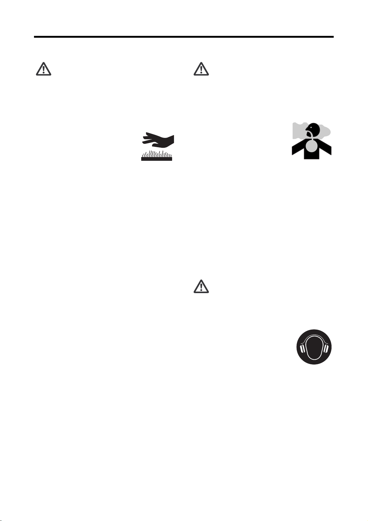
Warnings
The following two methods are used to call the attention of the operators and maintenance personnel to the
potential danger of the engine.
• Warning statements in the manual
• Warning labels affixed on the engine
Warning Statements
The warning statements in this manual describe potential danger in operating, inspecting or maintaining the
engine by using the following five classifications to indicate the degree of potential hazard. Failure to follow
these directions can lead to serious accidents which can result in personal injury, or death in the worst case.
Indicates a highly hazardous situation which, if not avoided, can result in
death or serious injury.
Indicates a potentially hazardous situation which, if not avoided, can result
in death or serious injury.
Indicates a potentially hazardous situation which, if not avoided, can result
in minor or moderate injury.
Indicates a potentially hazardous situation which, if not avoided, can result
in property damage.
Note Indicates important information or information which is useful for engine
operation.
Page 7

INTRODUCTION
Explanation of Terms
Abbreviations, Standards and Others
• API = American Petroleum Institute
• ASTM = American Society for Testing and Materials
• JIS = Japanese Industrial Standards
• MIL = Military Specifications and Standards (U.S.)
• MSDS = Material Safety Data Sheet
• SAE = Society of Automotive Engineers (U.S.)
• LLC = Long Life Coolant
Units of Measurement
Measurements are based on the International System of Units (SI), and they are converted to the metric sys-
tem units in this manual based on the following conversion rates.
• Pressure: 1 MPa = 10.197 kgf/cm
• Torque: 1 N⋅m = 0.10197 kgf⋅m
• Force: 1 N = 0.10197 kgf
• Horsepower: 1 kW = 1.341 HP = 1.3596 PS
• Meter of mercury: 1 kPa = 0.7 cmHg
• Meter of water: 1 kPa = 10.197 cmH
-1
• Engine speed: 1 min
= 1 rpm
2
2O (cmAq)
Page 8

Page 9

CONTENTS
Chapter 1 BASIC SAFETY PRECAUTIONS
Warning Fire and Explosion ...............1-1
Keep flames away............................................ 1-1
Keep engine and surrounding area clean ........ 1-1
Never open crankcase until engine cools ........ 1-1
Check for fuel, oil and exhaust gas leaks......... 1-1
Use flameproof light ......................................... 1-1
Do not short electrical wires ............................. 1-1
Keep fire extinguishers and first-aid kit
nearby .............................................................. 1-1
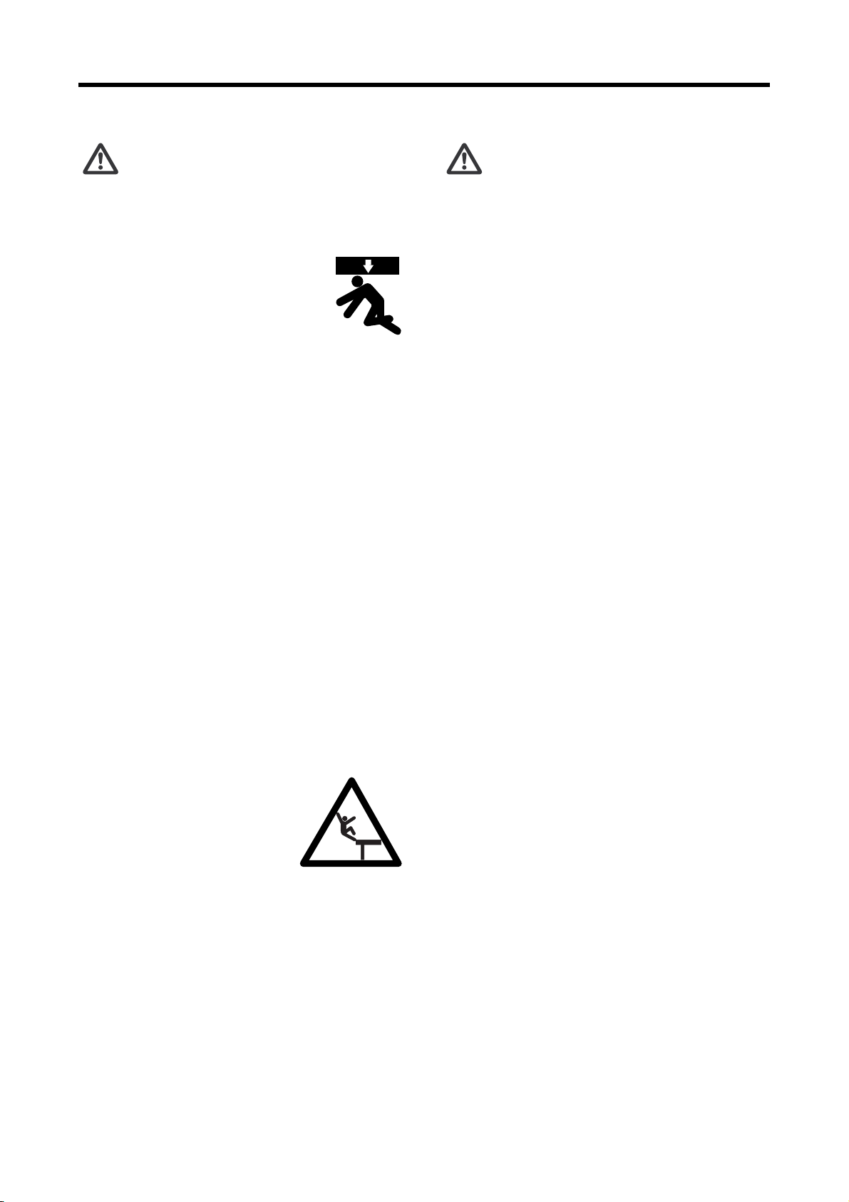
Warning Stay Clear of All Rotating and
Moving Parts........................................1-2
Install protective covers on rotating parts......... 1-2
Check surrounding area for safety ................... 1-2
Stay clear of all rotating and moving parts while
engine is operating........................................... 1-2
Lock out and Tag out ....................................... 1-2
Always stop engine before inspection and
maintenance..................................................... 1-2
Always return turning tools to original
position............................................................. 1-2
Warning Be Careful of Burns..............1-3
Do not touch engine during operation or
Engine Oil and LLC............................. 1-4
Use only specified fuel, engine oil and coolant
(LLC).............................................................. 1-4
Handle LLC carefully........................................ 1-4
Properly dispose of drained oil and LLC .......... 1-4
Caution Service Battery ..................... 1-5
Handle battery carefully ................................... 1-5
Caution When Abnormality Occurs.... 1-5
If engine overheats, conduct cooling operation
before stopping engine..................................... 1-5
If engine stops due to abnormality, exercise caution
when restarting................................................. 1-5
If engine oil pressure drops, stop engine
immediately ...................................................... 1-5
Caution Other Cautions ..................... 1-6
Never modify engine ........................................ 1-6
Never break seals ............................................ 1-6
Perform all specified pre-operation inspections and
periodic inspections.......................................... 1-6
Perform engine break-in................................... 1-6
Warm up engine before use............................. 1-6
Never operate engine under overload
condition ........................................................... 1-6
Conduct cooling operation before stopping
immediately after operation.............................. 1-3
Open radiator filler cap carefully ...................... 1-3
Add coolant only after coolant temperature
drops ................................................................ 1-3
Do not dismount heat protection covers........... 1-3
Warning Be Careful of Exhaust Fume
Poisoning.............................................1-3
Perform engine operation in a well-ventilated
site ................................................................... 1-3
Warning Protect Ears from Noises .....1-3
Wear earplugs.................................................. 1-3
Warning Be Careful When Lifting
Engine .................................................1-4
Lifting engine carefully ..................................... 1-4
Do not climb onto engine ................................. 1-4
Always watch your footing................................ 1-4
Caution Be Careful of Handling Fuel,
engine .............................................................. 1-6
Do not splash water on engine......................... 1-6
Conduct proper maintenance of air cleaner/pre-
cleaner ............................................................. 1-7
Observe safety rules at workplace ................... 1-7
Wear proper work clothes and protective gear. 1-7
Use appropriate tools for maintenance work.... 1-7
Cautions concerning transportation ................. 1-7
Do not operate engine continuously under low
load .................................................................. 1-7
Ventilate the engine room sufficiently .............. 1-7
Do not touch high-pressure injection fuel ......... 1-7
Caution About Warning Labels .......... 1-8
Maintain and inspect warning labels ................ 1-8
Warning labels ................................................. 1-9
CONTENTS-1
Page 10

CONTENTS
Chapter 2
NAME OF PARTS
Engine External Diagrams...................2-1
S12U Left View ................................................ 2-1
S12U Right View .............................................. 2-1
S16U Left View ................................................ 2-2
S16U Right View ............................................. 2-2
Equipment and Instrument ..................2-3
Starting and Shutdown Devices ....................... 2-3
Start Switch ............................................................. 2-3
Stop Switch ............................................................. 2-3
Start Lever ................................................................ 2-3
M
anual Stop Lever.................................................... 2-3
Instruments..........................................2-4
Tachometer............................................................... 2-4
Hour Meter................................................................ 2-4
Oil Pressure Gage .................................................... 2-4
Oil Temperature Gage.............................................. 2-4
Jacket Coolant Temperature Gage........................... 2-4
Oil Cooler Coolant Temperature Gage..................... 2-4
Air Cooler Coolant Temperature Gage ..................... 2-4
Jacket Coolant Pressure Gage................................. 2-4
Oil Cooler Coolant Pressure Gage ........................... 2-4
Air Cooler Coolant Pressure Gage ........................... 2-4
Exhaust Temperature Gage ..................................... 2-4
Fuel Pressure Gage.................................................. 2-4
Inlet Pressure Gage.................................................. 2-4
Engine Protection Devices ..................2-5
Low Oil Pressure Alarm............................................ 2-5
High Coolant Temperature Alarm ............................. 2-5
Oil Filter Clog Alarm.................................................. 2-5
Overspeed Alarm...................................................... 2-5
Using Turning Gear .............................2-6
Chapter 3 OPERATION
Preparation for Operation of New or
Overhauled Engine..............................3-1
Fuel System ..................................................... 3-1
Pouring fuel............................................................... 3-1
Bleeding Fuel System............................................... 3-2
Bleeding Air from Fuel Filters
(Wire-Element Type)................................................. 3-2
Bleeding Air from Fuel Feed Pipe............................. 3-3
Lubricating System........................................... 3-4
Pouring engine oil..................................................... 3-4
Cooling System ................................................ 3-5
Pouring coolant......................................................... 3-5
Electrical Systems............................................ 3-6
Checking Battery.............................................. 3-6
Electrolyte level..........................................................3-6
Checking specific gravity of electrolyte......................3-6
Checking loosened wire ................................... 3-6
Checking Valves for Open/Closed Position...... 3-7
Test Operation ................................................. 3-7
Normal Engine Operation ................... 3-8
Preparations for Operation
(Pre-Start Inspection) ....................................... 3-8
External Inspection....................................................3-8
Cleaning Fuel Filters (Wire-Element Type)................3-8
Checking Fuel Level in Tank .....................................3-9
Draining Water from Fuel Tank..................................3-9
Checking Engine Oil Level.........................................3-9
Checking Coolant Level...........................................3-10
Inspection of Air Cleaner Indicator...........................3-10
Draining Water from Air Starter Tank ......................3-11
Inspection of Air Tank Air Pressure .........................3-11
Starting.............................................. 3-12
Warming-up Operation ................................... 3-12
Inspection of Oil Pressure........................................3-12
External Inspection during Warming-up...................3-12
Operation ....................................................... 3-13
Inspection During Operation....................................3-13
Stopping ......................................................... 3-14
Emergency Stop............................................. 3-14
Inspection After Stopping ............................... 3-14
Chapter 4 MAINTENANCE
Cautions Concerning Maintenance..... 4-1
Stop the engine before checking or adding fuel, oil or
coolant. ......................................................................4-1
Handle electrolyte carefully........................................4-1
Handle LLC carefully. ................................................4-1
Always wear protective gear......................................4-1
Use recommended fuel, engine oil and coolant.........4-1
Perform all specified pre-start inspections and periodic
inspections.................................................................4-1
Use only genuine Mitsubishi parts.............................4-1
Fuel ..................................................... 4-2
Recommended Fuel ......................................... 4-2
Handling Fuel ................................................... 4-2
Engine Oil ........................................... 4-4
Recommended Engine Oil ............................... 4-4
CONTENTS-2
Page 11

CONTENTS
Selection of Oil Viscosity .......................................... 4-4
Handling Engine Oil ......................................... 4-5
Coolant ................................................4-6
Recommended Coolant ................................... 4-6
Long Life Coolant (LLC)................................... 4-6
Recommended LLC ......................................... 4-7
Features and Performance of Recommended
LLC .................................................................. 4-7
Maintenance of LLC ......................................... 4-7
Replacement timing of LLC ...................................... 4-7
LLC concentration..................................................... 4-7
Importance of LLC............................................ 4-8
Characteristics of LLC Additive and Important
Notes................................................................ 4-8
Examples of Abnormalities Caused by LLC..... 4-8
Pitting on iron parts................................................... 4-8
Corrosion of aluminum parts..................................... 4-8
Pitting and clogging of radiator ................................. 4-8
Filters...................................................4-9
Electrical Parts.....................................4-9
Cautions in Operating Engine in Cold
Weather Season................................4-10
Fuel ................................................................ 4-10
Engine Oil....................................................... 4-10
Coolant........................................................... 4-10
Battery............................................................ 4-10
Maintenance After Cold Season .................... 4-10
General definition of emergency engine....................5-2
General definition of general-purpose engine............5-2
Periodic Maintenance Chart for Engine in
Regular Use ........................................ 5-3
Periodic Maintenance Chart for
Emergency Engine.............................. 5-8
Periodic Maintenance Chart for General-
Purpose Power Supply Engine ......... 5-13
Chapter 6 PERIODIC INSPECTION AND MAINTENANCE PROCEDURES
Fuel System ........................................ 6-1
Draining Water from Fuel Filters
(Wire-Element Type)..................................................6-1
Draining Water from Fuel Filters
(Center-Bolt Type) .....................................................6-1
Draining Water from Fuel Tank..................................6-2
Cleaning inside of Fuel Filters
(Wire-Element Type)..................................................6-2
Changing Fuel Filters (Center-Bolt Type)......... 6-3
Changing Fuel Filters (Cartridge Type) ............ 6-4
Changing Fuel Filters with Engine Stop.....................6-4
Changing Fuel Filters while Engine in
Operation...................................................................6-5
Inspection of Fuel Control Linkage Ball
Joints................................................................ 6-6
Lubricating System ............................. 6-7
Changing Engine Oil, Oil Filters and Bypass Oil
Chapter 5 PERIODIC MAINTENANCE CHART
How to Use Periodic Maintenance
Chart....................................................5-1
Periodic Maintenance Chart............................. 5-1
Periodic maintenance chart for regular-use
engine ....................................................................... 5-1
Periodic maintenance chart for emergency
engine ....................................................................... 5-1
Periodic maintenance chart for general-purpose
engine ....................................................................... 5-1
General Definition of Regular-Use Engine,
Emergency Engine and General-Purpose
Engine .............................................................. 5-2
General definition of regular-use engine................... 5-2
Filter ................................................................. 6-7
Draining Engine Oil....................................................6-7
Changing Oil Filters (S12U).......................................6-7
Changing Oil Filters (Swithover Type)
(S12U) .............................................................. 6-8
Changing Oil Filters with Engine Stop .......................6-8
Changing Oil Filters While Engine in Operation ........6-8
Changing Oil Filters (Swithover Type)
(S16U) .............................................................. 6-9
Changing Oil Filters with Engine Stop .......................6-9
Changing Oil Filters While Engine in Operation ........6-9
Changing Bypass Oil Filter ......................................6-10
Pouring Engine Oil...................................................6-11
Inspection of Engine Oil Leakage After Replacing
Oil Filter .......................................................... 6-11
CONTENTS-3
Page 12

CONTENTS
Inspection of Engine Oil for Mixing of Fuel and
Water.............................................................. 6-11
Analysis of Engine Oil Properties................... 6-12
Engine Oil Sampling Tool Sets and Ordering
Procedure ............................................................... 6-12
Cooling System .................................6-13
Checking LLC Concentration ......................... 6-13
Inspection and Replacement of Zinc Rods .... 6-13
Changing Coolant .......................................... 6-14
Draining Coolant..................................................... 6-14
Cleaning the Cooling System ................................. 6-14
Pouring coolant....................................................... 6-15
Inlet and Exhaust Systems................6-16
Inspection and Draining Water of Exhaust Pipes
and Exhaust Muffler ....................................... 6-16
Draining Water From Air Cooler Chamber and
Inspection for Water Leakage ........................ 6-16
Cleaning, Inspection and Changing
Pre-Cleaner.................................................... 6-16
Cleaning, Inspecting and Changing Air Cleaner
Element .......................................................... 6-17
Chapter 9
TROUBLESHOOTING
General Precautions ........................... 9-1
Contact a Mitsubishi Dealer for Repair
Service ............................................................. 9-1
Examination before Work ................................. 9-1
Notes Regarding Contamination ...................... 9-1
Notes Regarding Parts Handling ...................... 9-1
Work Safety...................................................... 9-1
Conditions Required for Proper Engine
Operation ......................................................... 9-2
Troubleshooting .................................. 9-3
Engine Turns, But It Does Not Start ................. 9-3
Engine Does Not Turn...................................... 9-5
Engine Output is Low.................................................9-6
Engine Knocks ................................................. 9-7
Engine Produces Large Amount of Smoke While in
Operation ......................................................... 9-8
Engine Operates at High Speed and Does Not
Stop.................................................................. 9-8
Malfunction of Lubricating System ................... 9-9
Air Starter System .............................6-18
Draining Water and Cleaning Air Starter
Strainer........................................................... 6-18
Draining Water from Air Starter Compressor . 6-18
Chapter 7 LONG-TERM STORAGE
Storing Engine in Non-Operable Condition for More
Than 3 Months ................................................. 7-1
Preparation for Storage ............................................ 7-1
Maintenance during Storage..................................... 7-1
Using Engine after Storage....................................... 7-1
Storing Engine in Operable Condition for More Than
3 Months .......................................................... 7-2
Operating Engine for Maintenance Purposes........... 7-2
Chapter 8 TRANSPORTATION
Lifting Engine Carefully .................................... 8-1
Chapter 10 MAIN SPECIFICATIONS
Main Specifications........................... 10-1
List of Illustrations
fig.1-1 Warning for flywheel entanglement..............1-9
fig.1-2 Warning for moving parts.............................1-9
fig.1-3 Warning for oil mist ......................................1-9
fig.1-4 Caution for footing........................................1-9
fig.1-5 Caution for electric shock.............................1-9
fig.1-6 Warning for rotating parts.............................1-9
fig.1-7 Caution for burns .........................................1-9
fig.1-8 Warning for rotating parts.............................1-9
fig.1-9 Caution for referring to manual ....................1-9
fig.1-10 Caution for burns .........................................1-9
fig.2-1 S12U engine left view ..................................2-1
fig.2-2 S12U engine right view................................2-1
CONTENTS-4
fig.2-3 S16U engine left view ..................................2-2
fig.2-4 S16U engine right view................................2-2
fig.2-5 Start switch and stop switch.........................2-3
Page 13

CONTENTS
fig.2-6 Start lever.................................................... 2-3
fig.2-7 Manual stop lever........................................ 2-3
fig.2-8 Air cleaner indicator .................................... 2-5
fig.2-9 Preparation for turning ................................ 2-6
fig.2-10 Turning........................................................ 2-6
fig.2-11 Locking turning gear.................................... 2-6
fig.3-1 Priming pump operating method................. 3-2
fig.3-2 Bleeing air from fuel filters
(wire-element type) ..................................... 3-2
fig.3-3 Bleeding air from fuel filters
(center-bolt type)......................................... 3-2
fig.3-4 Bleeding air from fuel filters
(cartridge-type)............................................ 3-3
fig.3-5 Fuel filter switchover cock........................... 3-3
fig.3-6 Bleeding air from fuel feed pipe (1)............. 3-3
fig.3-7 Bleeding air from fuel feed pipe (2)............. 3-3
fig.3-8 Oil filler and oil level gage ........................... 3-4
fig.3-9 Engine oil priming pump.............................. 3-4
fig.3-10 Coolant drain cock on the engine................ 3-5
fig.6-2 Draining water from fuel filter
(center-bolt type)..........................................6-1
fig.6-3 Draining water from fuel tank .......................6-2
fig.6-4 Cleaning inside of fuel filter
(wire-element) type).....................................6-2
fig.6-5 Changing fuel filters (center-bolt type).........6-3
fig.6-6 Fuel filter switchover handle.........................6-4
fig.6-7 Changing fuel filters (cartridge type) ............6-4
fig.6-8 Fuel filter switchover handle.........................6-5
fig.6-9 Changing fuel filters (cartridge type) ............6-5
fig.6-10 Inspection of the ball joints for
looseness.....................................................6-6
fig.6-11 Changing oil filter element (S12U) ...............6-7
fig.6-12 Inspection of oil filter ....................................6-7
fig.6-13 Changing oil filters (switchover type)........ 6-8
fig.6-14 Changing oil filter elements..........................6-9
fig.6-15 Oil filter switchover handle ...........................6-9
fig.6-16 Changing bypass oil filters .........................6-10
fig.6-17 Inspection of bypass oil filter......................6-10
fig.3-11 Coolant drain cock on the water pump........ 3-5
fig.3-12 Water tank coolant level.............................. 3-5
fig.3-13 Inspecting electrolyte level.......................... 3-6
fig.3-14 Inspecting specific gravity of electrolyte...... 3-6
fig.3-15 Checking valves for open/closed
position........................................................ 3-7
fig.3-16 Checking valves for open/closed position... 3-8
fig.3-17 Cleaning fuel filter (wire-element type)........ 3-8
fig.3-18 Draining water from fuel tank ...................... 3-9
fig.3-19 Oil filler and oil level gage ........................... 3-9
fig.3-20 Checking coolant level .............................. 3-10
fig.3-21 Air cleaner indicator .................................. 3-10
fig.3-22 Draining water from air starter tank........... 3-11
fig.3-23 Inspection of air tank air pressure............. 3-11
fig.3-24 Stop button................................................ 3-14
fig.3-25 Manual stop lever...................................... 3-14
fig.4-1 Recommended fuel..................................... 4-2
fig.4-2 Recommended fuel according to air
fig.6-18 Bypass oil filter...........................................6-10
fig.6-19 Oil filler and level gage...............................6-11
fig.6-20 Engine oil priming pump.............................6-11
fig.6-21 Engine oil sampling tool sets......................6-12
fig.6-22 Zinc rod good/bad......................................6-13
fig.6-23 Coolant drain cock (on engine) ..................6-14
fig.6-24 Coolant drain cock (on water pump) ..........6-14
fig.6-25 Coolant drain cock on the engine...............6-15
fig.6-26 Coolant drain cock on the water pump.......6-15
fig.6-27 Water tank coolant level.............................6-15
fig.6-28 Inspection and raining water of exhaust pipes
and exhaust muffler ...................................6-16
fig.6-29 Coolant drain cock on air cooler
chamber .....................................................6-16
fig.6-30 Cleaning pre-cleaner..................................6-16
fig.6-31 Removal of air cleaner element .................6-17
fig.6-32 Cleaning air cleaner element .....................6-17
fig.6-33 Inspecting air cleaner element ...................6-17
temperature................................................. 4-2
fig.4-3 Recommended oil viscosity according to air
temperature................................................. 4-4
fig.6-1 Draining water from fuel filter
(wire-element type) ..................................... 6-1
fig.6-34 Air cleaner indicator ...................................6-17
fig.6-35 Air starter strainer.......................................6-18
fig.6-36 Air starter compressor................................6-18
fig.8-1 Hangers for lifting.........................................8-1
fig.8-2 Lifting the engine..........................................8-1
CONTENTS-5
Page 14

CONTENTS
List of Tables
Table 3-1 Specific gravity of electrolyte.................. 3-6
Table 3-2 Data for rated speed............................. 3-13
Table 4-1 Recomended Fuel .................................. 4-2
Table 4-2 Fuel Use Limit Property Guideline.......... 4-3
Table 4-3 Water quality standards.......................... 4-6
Table 4-4 Recommended brands of LLC................ 4-7
Table 4-5 Recommended LLC concentration (for
reference only)........................................ 4-7
Table 5-1 Periodic maintenance chart for engine in
regular use.............................................. 5-3
Table 5-2 Periodic maintenance chart for emergency
engine..................................................... 5-8
Table 5-3 Periodic maintenance chart for general-
purpose power supply engine............... 5-13
Table 6-1 Engine oil sampling tool sets ................ 6-12
Table 7-1 Recommended rust-preventive
oil and corrosion inhibitor........................ 7-1
Table 9-1 Conditions required for proper engine
operation................................................. 9-2
Table 9-2 Engine turns, but it does not start........... 9-3
Table 9-3 Engine does not turn .............................. 9-5
Table 9-4 Engine output is low ............................... 9-6
Table 9-5 Engine knocks ........................................ 9-7
Table 9-6 Engine produces large amount of smoke while
in operation............................................. 9-8
Table 9-7 Engine operates at high speed and does not
stop......................................................... 9-8
Table 9-8 Malfunction of lubrication system ........... 9-9
Table 10-1 Main specifications table ...................... 10-1
CONTENTS-6
Page 15
Chapter 1 BASIC SAFETY PRECAUTIONS
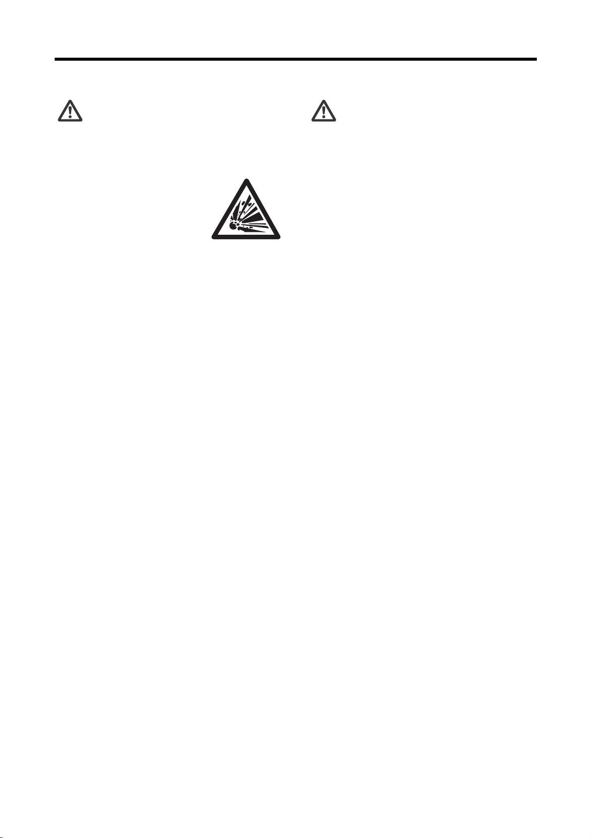
Warning Fire and Explosion
Keep flames away
Store fuel and engine oil in a
well-ventilated area.
Make sure that the caps of fuel
and engine oil containers are
tightly closed, and store them in
the designated site.
Do not use flames or smoke where fuel or oil is
handled or cleaning solvent is used for washing
parts.
Spilled fuel, oil and LLC should be wiped immedi-
ately and thoroughly. Spilled fuel, oil and LLC can
ignite and cause fire.
Keep engine and surrounding area clean
Do not store combustible (such as fuel, engine oil
and LLC), explosive or dangerous materials near
the engine. Those substances can cause a fire or
explosion.
Keep the engine and the surrounding area free of
dust, dirt and foreign materials, since they can
cause fire or the engine to overheat.
Clean the top surface of the battery after perform-
ing maintenance work. Dust on the battery may
cause a short-circuit.
The engine must be used at least 1 m [3.3 ft.] away
from buildings and other equipment to prevent pos
sible fire caused by engine heat.
Never open crankcase until engine cools
If the cover is opened while the engine is still hot,
fresh air comes into crankcase and oil mist can be
ignited by engine heat, then it may lead to the
explosion of the engine.
Never open the engine crankcase cover before the
engine becomes cool, wait at least 10 minutes after
the engine stops.
Check for fuel, oil and exhaust gas leaks
Inspect fuel, oil and exhaust pipes regularly for
damage and looseness. If a fuel, oil and exhaust
gas leak is found, repair the leakage immediately.
Fuel or oil spilled on a hot surface of the engine,
and exhaust gas blown onto a combustible material
may cause fire and result in personal injury and/or
damage to equipment.
Use flameproof light
When inspecting fuel, engine oil, coolant, battery
electrolyte, etc., use a flameproof light. An ordinary
light may ignite and cause an explosion.
Do not short electrical wires
Before inspecting or servicing any electrical compo-
nent, disconnect the ground cable from the nega-
tive (-) battery terminal to prevent short-circuit and
fire.
Loose terminals or damaged cables/wires can
cause a short-circuit that may result in fire. Before
operating the engine, inspect the cables and wires,
and repair or replace if necessary.
Keep fire extinguishers and firstaid kit nearby
Keep fire extinguishers nearby,
and be familiarized with their
usage.
Keep a first-aid kit at the desig-
nated place, and make sure it is
easily accessible at anytime.
Establish response procedures to follow in the
event of fire or accident, and post information con
cerning emergency contact locations and their con-
tact methods.
-
1-1
Page 16
Chapter 1 BASIC SAFETY PRECAUTIONS
Warning Stay Clear of All Rotating and Moving Parts
Install protective covers on rotating parts
Make sure the protective covers of
the engine are correctly installed.
Repair any damaged or loose covers.
When the engine is coupled to other
equipment or the radiator, install pro
tective covers on the exposed connecting belt and
coupling.
Never remove protective covers for rotating parts
such as the damper cover, camshaft cover or
rocker cover while the engine is operating.
-
Check surrounding area for safety
Before starting the engine, check to make sure no
one is near the engine and tools are not left on or
near the engine. Verbally notify persons within the
immediate area when starting the engine.
When the starter device is posted with a sign that
prohibits startup operation, do not operate the
engine.
Stay clear of all rotating and moving parts while engine is operating
Do not approach rotating and moving
parts of the engine while the engine is
in operation.
Rotating parts can entangle your
body or tools and result in serious
injury.
Keep items that can be easily entangled by rotating
parts away from the engine.
If your body or tool contacts rotating and moving
parts, serious injury may occur as a result.
Lock out and Tag out
Be sure to lock out and tag out before starting
inspection and maintenance.
Lockout and tagout are effective methods of cutting
off machines and equipment from energy sources.
To lock out and tag out, pull out the key from the
starter switch, turn off the battery switch, and post a
tag on the starter switch indicating “Do Not Oper
ate.” The starter key switch should be kept by the
person performing the inspection and maintenance.
For the air starter system, close the main valve of
the air tank, and post a tag indicating “Do Not Open
the Valve.”
-
Always stop engine before inspection and maintenance
Be sure to stop the engine before conducting
inspection and maintenance. Never attempt to
adjust the engine parts while the engine is running.
Conducting inspection and maintenance on an
operating engine can result in a serious accident of
entanglement by rotating parts.
Always return turning tools to original position
Be sure to remove all turning tools used during
maintenance and inspection.
Starting the engine with the turning tools inserted or
turning gears engaged may not only cause engine
damage but personal injury as well.
1-2
Page 17
Chapter 1 BASIC SAFETY PRECAUTIONS
Warning Be Careful of
Burns
Do not touch engine during operation or immediately after operation
Do not touch the main and exhaust
parts of the engine during operation
or immediately after operation to
prevent burns.
To conduct maintenance and
inspection, wait until the engine cools sufficiently as
indicated with the temperature gage.
Open radiator filler cap carefully
Never open the radiator filler cap while the engine
is operating or immediately after it is stopped.
The engine coolant is hot during engine operation
and immediately after operation. If the radiator filler
cap is opened when the coolant is at operating tem
perature, steam and hot coolant may blow out,
causing skin burns as a result.
When opening the cap, stop the engine and allow
the coolant temperature to drop sufficiently. Cover
the cap with a cloth or use thick rubber glove, and
then slowly open the cap.
When closing the cap, be sure to tighten securely.
Add coolant only after coolant temperature drops
Do not add coolant immediately after the engine
stops. Wait until the coolant temperature lowers
sufficiently to prevent burns.
Warning Be Careful of
Exhaust Fume Poisoning
Perform engine operation in a well-ventilated site
Exhaust gas from the engine
contains carbon monoxide and
other harmful substances.
Do not operate the engine in an
enclosed area (inside a ware
house, tunnel, etc.) or in a site where all sides are
blocked, since exhaust fumes can cause gas poi
soning.
If the engine must be operated in an enclosed area,
discharge the exhaust gas to the outside and pro
vide adequate ventilation.
Connect an exhaust duct to the exhaust pipe to
lead exhaust gas to the outside, and make sure
exhaust gas does not leak from the duct joints.
-
Make sure the exhaust gas does not blow in the
direction of plants or animals.
-
-
-
Warning Protect Ears
from Noises
Wear earplugs
Be sure to wear earplugs when
entering into the engine room.
The earplugs can be quite use
ful to protect ears from various
engine noises.
-
Do not dismount heat protection covers
The high-temperature exhaust components are
installed with heat protection covers. Do not dis
mount these heat protection covers. If they must be
removed during inspection and maintenance, be
sure to reinstall them after completing the inspec
tion and maintenance.
-
-
1-3
Page 18
Chapter 1 BASIC SAFETY PRECAUTIONS
Warning Be Careful
When Lifting Engine
Lifting engine carefully
To lift the engine, use slings capa-
ble of supporting the weight of the
engine.
Attach appropriate slings to the
hangers on the engine.
Keep the engine balanced during lifting by consid-
ering the center of gravity of the engine.
Keep the angle formed by slings attached to hang-
ers within 60°. If the angle exceeds this limit, exces-
sive load is applied on the hangers and may
damage the hangers.
If wire ropes contact the engine, place a cloth or
other soft padding to prevent damage to the engine
and wire ropes.
Do not climb onto engine
Never climb onto the engine.
To work on parts located on the upper section, use
a ladder, stand, etc.
Climbing on the engine can not only damage entire
parts, but also cause parts to fall off and result in
injury.
Always watch your footing
Use a stable work platform to
stand on when working on the
upper part of the engine and
other hard-to-reach places.
Standing on a decrepit stand or
parts box may result in personal injury.
Do not put obstacles on the stand.
Caution Be Careful of Handling Fuel, Engine Oil and LLC
Use only specified fuel, engine oil and coolant (LLC)
Use fuel, oil and LLC specified in this manual, and
handle them carefully.
Use of any other fuel, oil or LLC, and improper han-
dling may cause various engine problems and mal-
functions.
Obtain the MSDSs issued by the fuel, oil and LLC
suppliers, and follow the directions on the MSDSs
for proper handling.
Handle LLC carefully
Wear safety mask and rubber gloves when han-
dling LLC. Avoid contact with skin and eyes to pre-
vent personal injury.
Should LLC be accidentally swallowed, induce
vomiting immediately and seek medical attention.
Should LLC enter eyes, flush immediately with
plenty of water and seek medical attention. If LLC is
spilled on skin or clothes, wash immediately with lot
of water.
Keep flammable materials away from LLC to pre-
vent fire. Never use flames or generate sparks near
LLC since flames or sparks can cause fire.
Drained LLC is harmful. Do not dispose of into con-
ventional sewage. Contact a Mitsubishi dealer for
the disposal of drained LLC.
Properly dispose of drained oil and LLC
Do not dispose of engine oil, used cleaning oil or
LLC into conventional sewage.
Prepare drip pan or other containers to receive oil
and LLC drained from the engine. Do not drain
them directly onto the ground.
For disposal of drained oil and LLC, consult a Mit-
subishi dealer.
1-4
Page 19
Chapter 1 BASIC SAFETY PRECAUTIONS
Caution Service Bat-
tery
Handle battery carefully
• Batteries release flammable
hydrogen gas and oxygen.
Never use flames or generate
sparks near the battery since
flames or sparks can cause
an explosion.
• Do not use the battery when the fluid surface is
lower than the minimum required level. Using a
battery with a low electrolyte level can result in an
explosion.
• Do not short the battery terminals with a tool or
other metal object.
• When disconnecting battery cables, remove the
cable from the negative (-) terminal first. When
reconnecting cables, attach the cable to the posi-
tive (+) terminal first.
• Charge the battery in a well-ventilated area, with
all filling hole plugs removed.
• Make sure the cable clamps are securely
installed on the battery terminals. A loose cable
clamp can cause sparks that may result in an
explosion.
• Before servicing electrical components or con-
ducting electric welding, set the battery switch to
the [OFF] position or disconnect the cable from
the negative (-) battery terminal to cut off the
electrical current.
• Electrolyte contains dilute sulfuric acid. Careless
handling of the battery can cause loss of sight
and burns.
• Wear safety goggles and rubber gloves when
working with the battery (replenishment of fluid,
charging, etc.)
• If electrolyte is spilled on skin or clothes, wash
immediately with lots of water. Then, use soap to
clean thoroughly.
• If electrolyte enters eyes, flush immediately with
lots of fresh water and see a physician as soon as
possible.
• Should you accidentally swallow electrolyte, gar-
gle with plenty of water, then drink lots of water.
Consult a physician immediately.
Caution When Abnormality Occurs
If engine overheats, conduct cooling operation before stopping
engine
If the engine overheats, do not stop the engine
immediately. Abrupt stopping of an overheated
engine may cause the coolant temperature to rise,
resulting in seizing of the engine. If the engine over
heats, operate the engine at low idling speed (cool-
ing operation), and stop the engine after the coolant
temperature lowers sufficiently.
Do not add coolant immediately after stopping the
engine. Adding coolant to a hot engine may cause
damage to the cylinder head from sudden change
in temperature. Add coolant gradually after the
engine cools to room temperature.
If engine stops due to abnormality, exercise caution when restarting
If the engine stops due to an abnormality, do not
restart the engine immediately. If the engine stops
with an alarm, check and correct the cause of the
problem before restarting. Operating the engine
without correcting the problem may result in serious
engine problems.
If engine oil pressure drops, stop engine immediately
If the engine oil pressure decreases, stop the
engine immediately, and inspect the lubricating sys
tem including the oil level and pump. Operating the
engine with low oil pressure may cause seizing of
bearings and other parts.
-
-
1-5
Page 20

Chapter 1 BASIC SAFETY PRECAUTIONS
Caution Other Cautions
Never modify engine
Unauthorized modification of the engine will void
the maker's warranty.
Modification of the engine may not only cause
engine damage but may result in personal injury as
well.
If there is a need to modify the engine, please con-
tact a Mitsubishi dealer.
Never break seals
To ensure proper engine operation, the fuel control
links are attached with seals that prevent accidental
change of the injection volume and rotation speed
settings. Operating the engine without these seals
in place can result in the following problems, and
also invalidates the warranty.
• Rapid wear of moving and rotating parts
• Engine damage such as seizing of engine parts
• Increased consumption of fuel and lubricating oil
• Degradation of engine performance due to
improper balance between fuel injection volume
and governor operation.
Perform all specified pre-operation inspections and periodic
inspections
Conduct the pre-operation inspections and periodic
inspections as described in this manual.
Failure to conduct the specified inspections may
cause various engine problems and damage to
parts, as well as serious accidents.
Perform engine break-in
Break in a new engine by operating it with a light
load and at a speed lower than normal during the
first 50 hours of operation.
Operating a new engine under high load or severe
conditions during the break-in period can shorten
the service life of the engine.
Warm up engine before use
If the auxiliary devices for the starter (water heater,
engine oil priming pump etc.) are not installed, let
the engine idle for 5 to 10 minutes before using the
engine for work.
Warm-up operation circulates lubricants in the
engine and contributes to a longer service life and
economical operation.
Do not conduct warm-up operation for an extended
period of time. Prolonged warm-up operation
causes carbon build-up in the cylinders that leads
to incomplete combustion.
Never operate engine under overload condition
If the engine shows an overload condition such as
the emmision of exhaust smoke, decrease the load
immediately so that the engine operates at appro
priate output and load.
Overloading the engine causes not only high fuel
consumption but also excessive carbon deposits
inside the engine. Carbon deposits cause various
problems and can shorten the service life of the
engine.
-
Conduct cooling operation before stopping engine
Before stopping the engine, let it idle at low speed
for 5 to 6 minutes to cool.
Stopping the engine immediately after high-speed
operation can cause engine parts to heat up and
shorten the service life of the engine.
During cooling operation, check the engine for
abnormalities.
Do not splash water on engine
Do not allow rainwater, etc., to enter the engine
through the air inlet or exhaust openings.
Do not wash the engine while it is in operation,
since the engine may suck in the cleaning fluid
(water). If the engine is started with water inside the
combustion chambers, water hammer action can
damage the engine and result in serious accidents.
1-6
Page 21

Chapter 1 BASIC SAFETY PRECAUTIONS
Conduct proper maintenance of air cleaner/pre-cleaner
The major cause of abnormal wear on engine parts
is dust entering with intake air. Worn parts result in
an increase of oil consumption, decrease of output,
and starting difficulties. Conduct maintenance of
the air cleaner/pre-cleaner according to the follow
ing directions to ensure optimum air filtering perfor-
mance.
• Do not conduct maintenance of the air cleaner/
pre-cleaner while the engine is operating.
Without the air cleaner/pre-cleaner in place, the
turbocharger can suck foreign particles into the
engine, decrease the load immediately so that
the engine operates at appropriate output and
load.
• When removing the air cleaner, do not allow dust
attached on the air cleaner/pre-cleaner to enter
into the engine.
• If equipped with a dust indicator, conduct mainte-
nance only when the clog warning sign appears.
While servicing the air cleaer/pre-cleaner, do not
let dust enter into the air cleaner/pre-cleaner,
damage or deform the element.
Observe safety rules at workplace
Observe the safety rules established at your work-
place when operating and maintaining the engine.
Do not operate the engine if you are feeling ill.
Operation of the engine with reduced awareness
may cause accidental operations that may result in
accidents. In such case, you should inform your
supervisor of your condition.
When working in a team of two or more persons,
use specified hand signals to communicate among
the workers.
Wear proper work clothes and protective gear
Wear the work clothes specified by your workplace.
Wear a hardhat, face shield, safety shoes, dust pro-
tective mask, gloves and other protective gear as
needed.
When handling compressed air, wear safety gog-
gles, hardhat, gloves and other necessary protec-
tive gear. Compressed air may cause personal
injury when not wearing the proper protective gear.
Use appropriate tools for maintenance work
Use appropriate tools according to the type of
maintenance work, and use them correctly.
If tools are damaged, replace with new tools.
-
Cautions concerning transportation
When transporting the engine using a truck, con-
sider the engine weight, width and height to ensure
safety. Abide by the pertinent laws and regulations.
Do not operate engine continuously under low load
When operating the engine with a 30 % load or
lower, limit each operation to 10 minutes. Operating
the engine under low load tends to result in
unburned fuel, which can adhere on internal engine
parts to cause malfunctions and shorten the engine
service life.
Ventilate the engine room sufficiently
Be sure to provide sufficient ventilation in the
engine room. Insufficient air in the room can cause
the engine temperature to rise and the output
power and performance to lower.
It is highly recommended to calculate the required
amount of air supply to the engine and install an
appropriate ventilation system before installing an
engine.
Do not touch high-pressure injection fuel
Should injected fuel leak from a fuel injection pipe,
do not touch the spurting fuel.
Fuel in the fuel injection pipes is under high pres-
sure. Touching high-pressure fuel can cause the
fuel to penetrate the skin and result in gangrene.
1-7
Page 22

Chapter 1 BASIC SAFETY PRECAUTIONS
Caution About Warning Labels
Maintain and inspect warning labels
Make sure all warning labels are legible.
If the description and/or illustration on a warning
label cannot be seen clearly, clean or replace the
label.
To clean warning labels, use a cloth, water and
soap. Do not use solvents, gasoline or other chemi
cals to clean warning labels. Cleaning with chemi-
cals may cause the labels to peel off.
If warning labels are damaged or missing, replace
with new labels.
If a part of the engine with warning label is replaced
with new part, also attach new warning label to the
new part.
To obtain replacement warning labels, contact a
Mitsubishi dealer.
-
1-8
Page 23
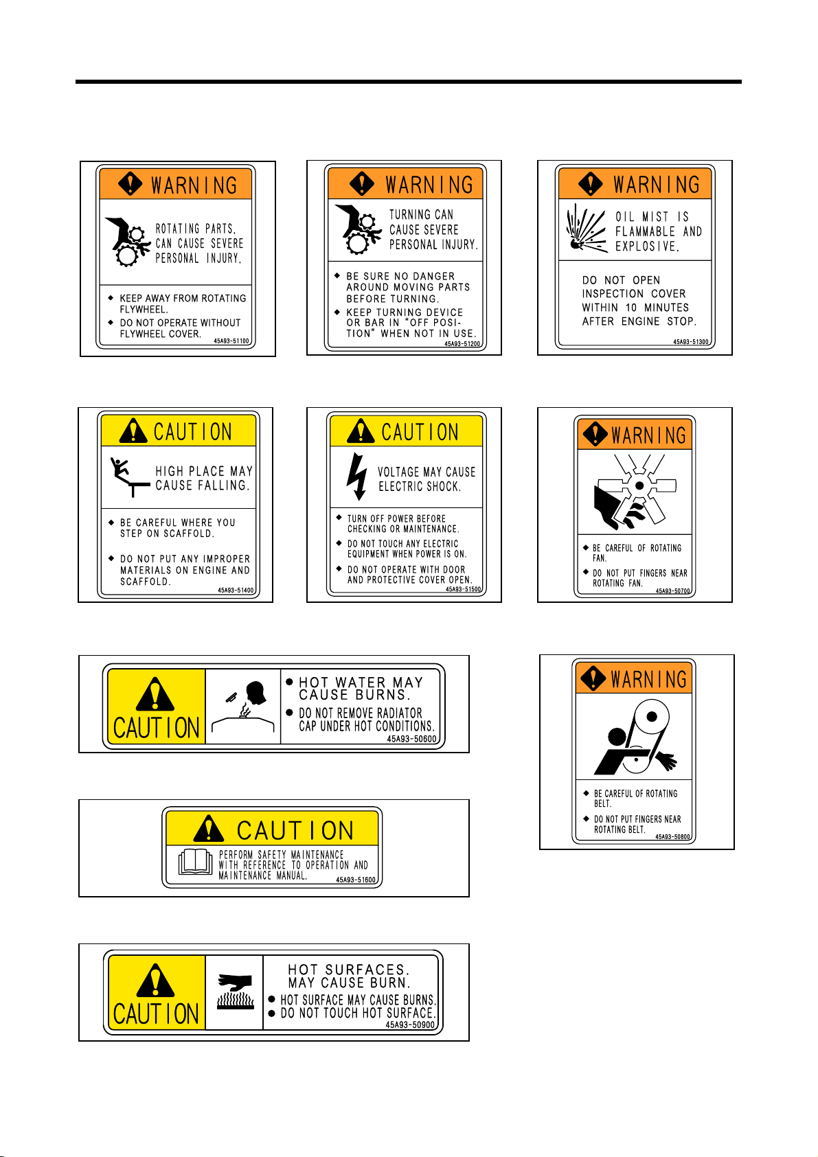
Warning labels
Chapter 1 BASIC SAFETY PRECAUTIONS
fig.1-1 Warning for flywheel
entanglement
fig.1-4 Caution for footing fig.1-5 Caution for electric shock
fig.1-2 Warning for moving parts fig.1-3 Warning for oil mist
fig.1-6 Warning for rotating parts
fig.1-7 Caution for burns
fig.1-9 Caution for referring to manual
fig.1-10 Caution for burns
fig.1-8 Warning for rotating parts
1-9
Page 24

Page 25
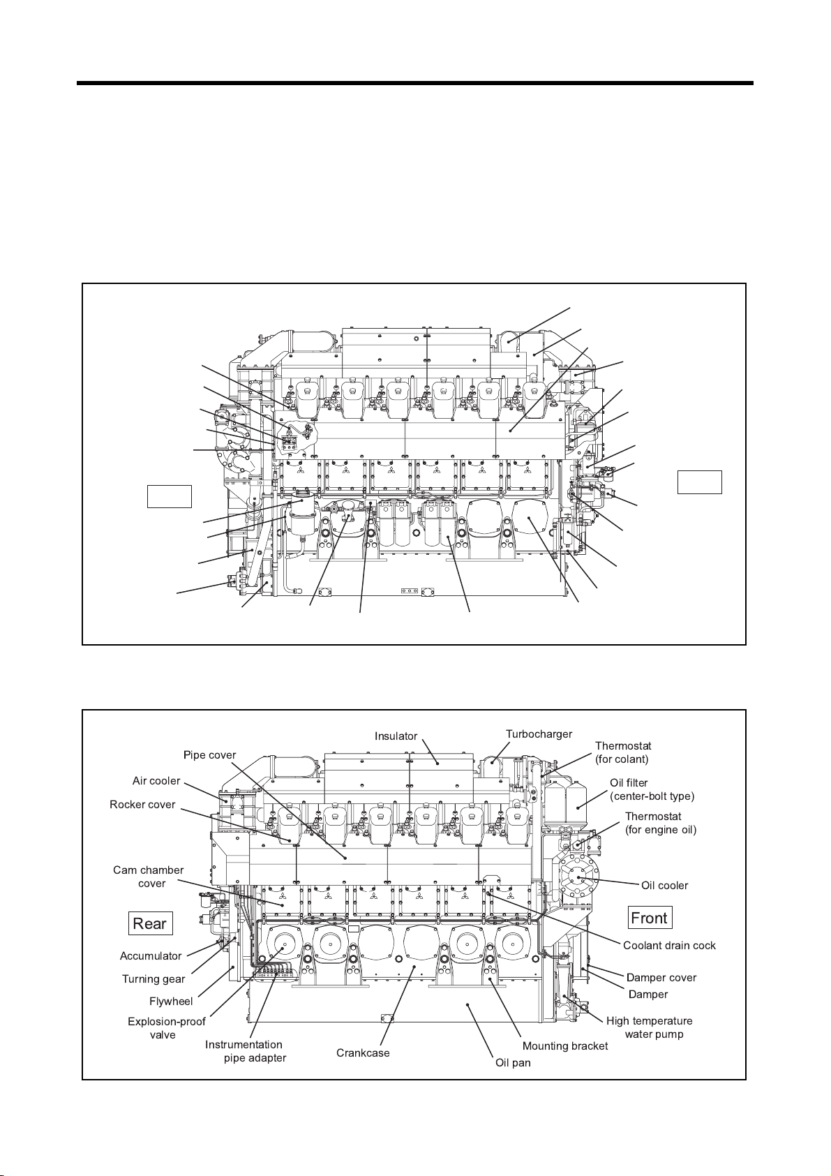
Chapter 2 NAME OF PARTS
Engine External Diagrams
The external diagram is for standard type of S12U/S16U engine.
The installed equipment and shapes differ on the engine type.
S12U Left View
Cylinder head
Fuel injection pipe
Fuel injection pump
Air starter main pipe
Distributor
Front
Breather
Oil level gage
Low temoerature
water pump
Oil pump
Front gear case
Oil filler
Nameplate
Bypass oil filter
Turbocharger
Silencer, pre-cleaner
Pipe cover
Air cooler
Fuel filter
(center-bolt type)
Air cooler chamber
water drain cock
Governor
Governor oil filter
Rear
Fuel feed pump
Fuel priming pump
Fuel filter
(wire-element type)
Timing gear case
Crankcase side cover
S12U Right View
%
!"
&'$
#
fig.2-1 S12U engine left view
$ "
!
#
fig.2-2 S12U engine right view
2-1
Page 26

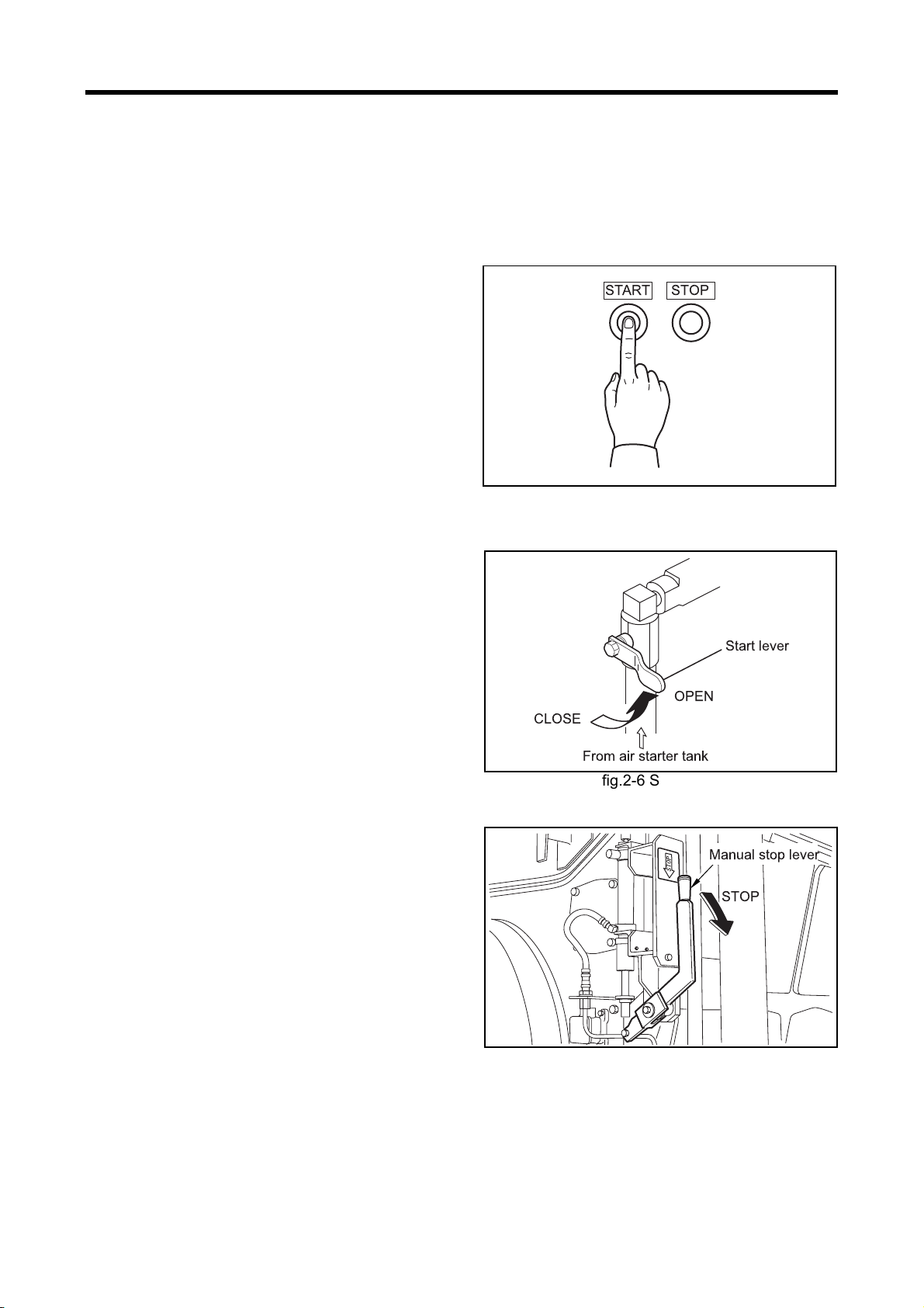
Chapter 2 NAME OF PARTS
r
S16U Left View
Fuel injection pipe
Turbocharger
Silencer
Pre-cleaner
Air starter
main pipe
Damper cover
Front
Damper
Breather
Oil filler
Low temperature
water pump
Front gear case
S16U Right View
Nameplate
Oil level gage
Bypass oil filter
fig.2-3 S16U engine left view
Fuel injection pump
Pipe cover
Cylinder head
Fuel filter
(center-bolt type)
Coolant drain cock
Governor
Rear
Governor oil filte
Fuel feed pump
Fuel priming pump
Fuel filter
(wire-element type)
Crankcase side cover
!
"
!
#$%
fig.2-4 S16U engine right view
#
&
%
2-2
Page 27
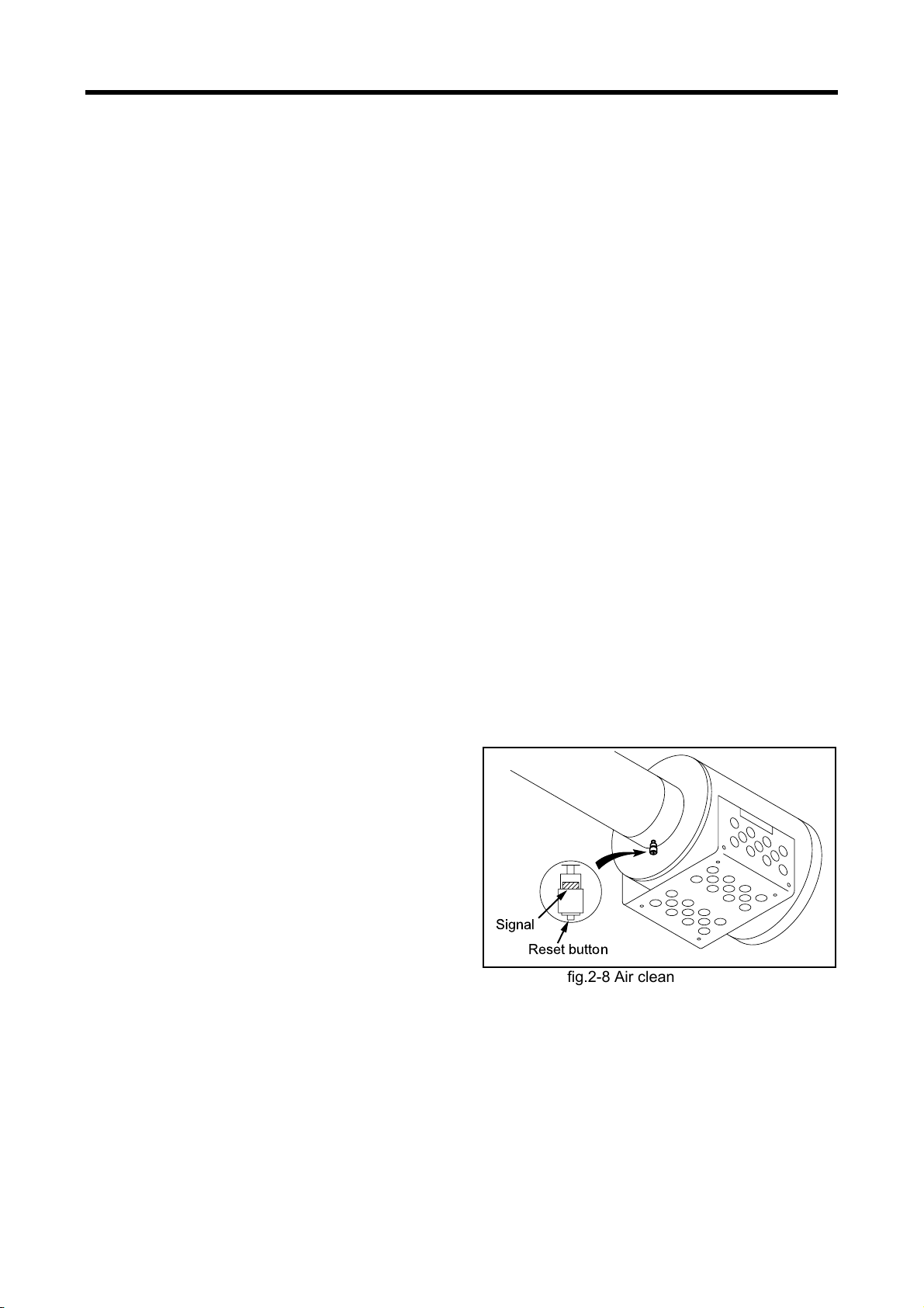
Chapter 2 NAME OF PARTS
Equipment and Instrument
Starting and Shutdown Devices
The shape and type of the starting and shutdown devices may vary from those described below depending on
the engine specifications.
Start Switch
When the start switch on the operation panel is
pressed, starting air is supplied to the air starter
system and cranks the engine.
Stop Switch
When the stop switch on the operation panel is
pressed, the shutdown cylinder operates and
moves the control shaft of the fuel injection pump to
the no-injection position to shut down the engine
operation.
fig.2-5 Start switch and stop switch
STOPSTART
Start Lever
The start lever is provided on the air starter pipe.
When the lever is moved toward the OPEN posi
tion, air flows and cranks the engine. Once the
engine starts, return the lever to the CLOSE posi
tion immediately.
Manual Stop Lever
Use the manual stop lever to shut down the engine
in the event of an emergency.
If the stop button is not working, use the manual
stop lever. The lever is installed to the fuel control
link and when the lever is moved in the STOP
direction, the engine stops operation.
Should the engine continue operating even after
the manual stop lever is operated, cut off the fuel
supply to stop the engine.
-
-
Start lever
OPEN
CLOSE
From air starter tank
fig.2-6 Start lever
fig.2-7 Manual stop lever
2-3
Page 28

Chapter 2 NAME OF PARTS
Instruments
The instruments indicate the internal conditions of
the engine in operation. In normal operation, record
the numerical values indicated on the instruments
at regular intervals. If the numerical value is far dif
ferent from that in normal operation, the indications
of the instruments allow prompt judgment of engine
problems.
The instrument shape (round, square) and indica-
tion type (analog, digital) can vary depending on
the engine specifications.
Tachometer
This indicates the engine revolutions per minute
(rpm).
Note: The tachometer may have a built-in hour
meter.
Hour Meter
This indicator shows cumulative engine operating
hours.
Use the meter indication as a guigeline for deter-
mining the need for regular inspection and servic-
ing.
Oil Cooler Coolant Pressure Gage
This indicates the coolant pressure in the oil cooler.
-
Air Cooler Coolant Pressure Gage
This indicates the coolant pressure in the air cooler.
Exhaust Temperature Gage
This indicates the temperature of exhaust gas at
the cylinder outlets or turbocharger inlet or outlet.
Fuel Pressure Gage
This indicates the pressure of fuel supplied to the
fuel injection pump by the fuel feed pump.
Inlet Pressure Gage
This indicates the pressure of inlet supplied to the
air cooler.
Oil Pressure Gage
This indicates the engine oil pressure.
Oil Temperature Gage
This indicates the engine oil temperature.
Jacket Coolant Temperature Gage
This indicates coolant temperature inside of the
crankcase.
Oil Cooler Coolant Temperature Gage
This indicates coolant temperature in the oil cooler.
Air Cooler Coolant Temperature Gage
This indicates coolant temperature in the air cooler.
Jacket Coolant Pressure Gage
This indicates the pressure of coolant in the crank-
case, cylinder heads and other parts.
2-4
Page 29
Chapter 2 NAME OF PARTS
Engine Protection Devices
The engine protection devices activate an alarm when an abnormality occurs in the engine in order to protect
the engine and prevent serious problems and accidents. When a protection device is activated, stop the
engine, examine the cause of the abnormality, and take corrective measures.
If the cause of the problem is unknown, contact a Mitsubishi dealer.
Protection devices installed on the engine and their types (setting values) and shapes vary depending on the
engine specifications. The following describes the typical protection devices installed in a Mitsubishi engine.
Low Oil Pressure Alarm
The oil pressure switch activates an alarm when the engine oil pressure drops to an abnormally low level.
High Coolant Temperature Alarm
The high coolant temperature alarm device generates a warning or stops the engine when the coolant tem-
perature rises to an abnormally high level due to an engine malfunction or other reason.
Oil Filter Clog Alarm
The oil filter clog detector generates a warning when the oil filter becomes clogged and causes an abnormally
large pressure difference between before and after the oil filter. When it generates an alarm, replace it with a
new filter immediately and change engine oil, as well.
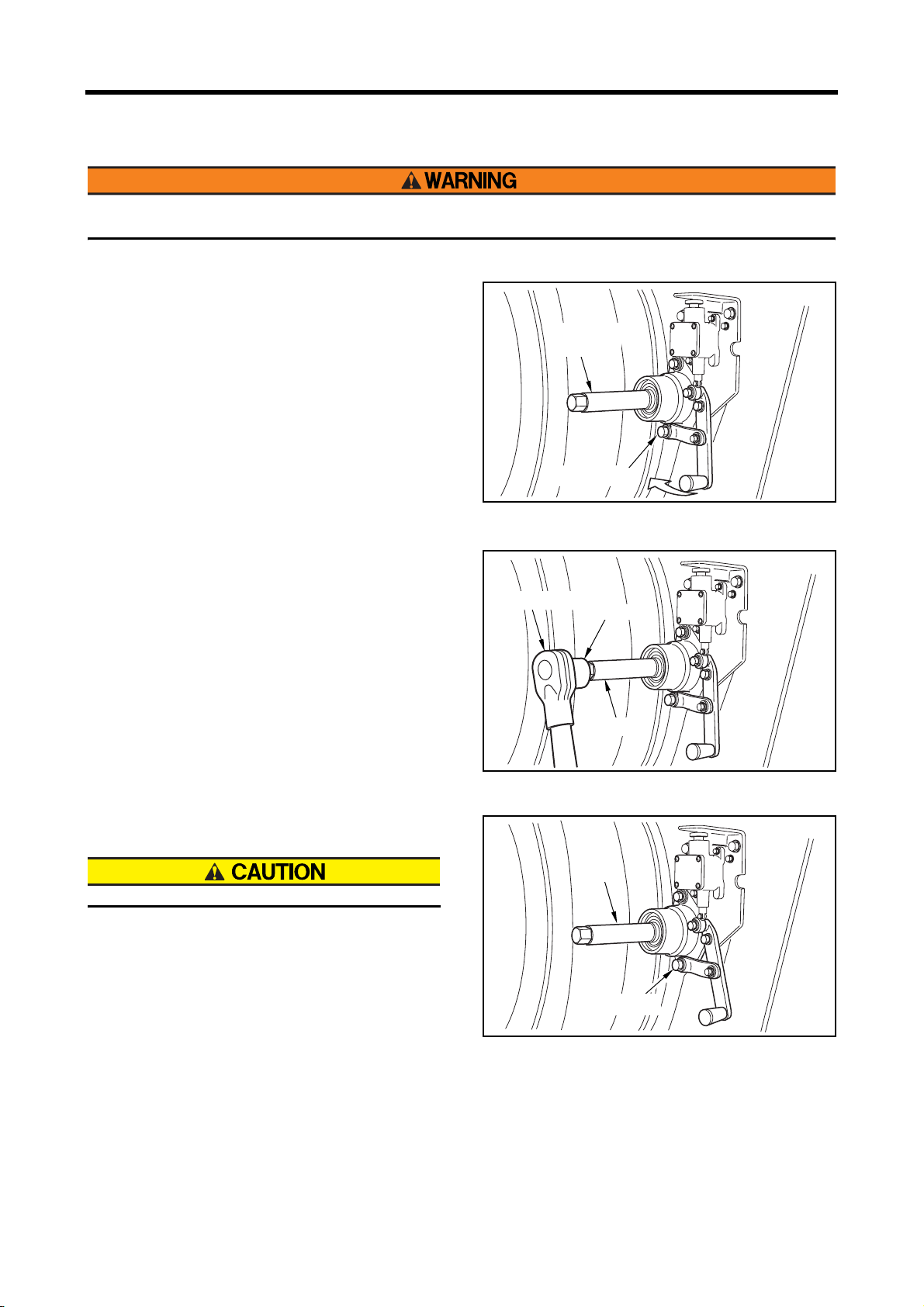
Overspeed Alarm
The overspeed alarm device generates a warning and stops the engine operation when the engine speed
starts operating at abnormally high speed due to an engine malfunction or other reason.
Air Cleaner Clog Alarm (Air Cleaner Indicator)
A red signal appears as a warning when the air cleaner
element becomes clogged and causes an abnormally
large pressure difference between before and after the
air cleaner. When a red signal appears, clean the air
cleaner element immediately or replace it with a new
element.
After the element is cleaned or replaced, press the
reset button located at the upper part of the indicator to
cancel the red signal.
While serving the air cleaner, do not enter dust into the
air cleaner or damage the element.
Signal
Reset button
fig.2-8 Air cleaner indicator
2-5
Page 30
Chapter 2 NAME OF PARTS
Using Turning Gear
Before starting the engine, return (pull out) the turning gear to the original position. Starting the engine with the
turning gear pushed in not only damages the ring gear but also may result in personal injury.
1 Untighten the retaining bolt.
2 Move the turning gear fully to engage the ring gear
and tighten the bolt.
Turning gear
shaft
Retaining bolt
fig.2-9 Preparation for turning
3 Turn the shaft using the socket wrench and the
rachet handle.
4 After turning, move the turning gear, disengage the
turning gear with the ring gear and tighten the retain-
ing bolt.
Make sure the lock pin is securely inserted.
Rachet handle
Socket
Shaft
fig.2-10 Turning
Shaft
Retaining bolt
fig.2-11 Locking turning gear
2-6
Page 31

Chapter 3 OPERATION
Preparation for Operation of New or Overhauled Engine
Before operating a new or overhauled engine, do the following inspection. For second operation onward, do
the following normal operation outlined on page
Fuel System
When handling fuel, make sure there are no flames near the engine.
Wipe any spilled fuel completely. Spilled fuel can ignite and cause fire.
Do not remove the strainer when filling the fuel tank.
Use fuel specified in "Fuel" (4-2).
Pouring fuel
3-8 "Normal Engine Operation".
1 Make sure the insides of the fuel tank and fuel pipes are clean.
2 Pour fuel into the fuel tank.
3 Remove the fuel feed pipe and drain plug from the fuel inlet of the engine, and check the discharged fuel
for dust particles.
4 Reinstall the drain plug and fuel feed pipe.
5 Add fuel until the fuel level gage indicates "FULL."
3-1
Page 32

Chapter 3 OPERATION
Bleeding Fuel System
When fuel overflows from the air vent plug, wipe
thoroughly with a cloth. Spilled fuel is a fire haz-
ard.
After bleeding, lock the priming pump cap
securely. If the cap is not locked tightly, the
priming pump can be damaged, causing fuel
leakage that may lead to a fire.
Closing all air vent plugs before locking the priming
pump cap disallows the priming pump cap from
returning to the original position due to internal pres-
sure.
Bleed air from the location closest to the fuel tank
that are the fuel filter (wire-element type), fuel filter
(center-bolt type), then the fuel feed pipe.
Bleeding Air from Fuel Filters (Wire-Element Type)
[Unlock]
Turn counterclockwise
[Priming]
Move back and force
Priming pump cap
[Lock]
Press the cap
and turn clockwise
fig.3-1 Priming pump operating method
Replace to a new part if there is a damage on the air
vent plug, thread area of bracket or sealing washer.
1 Loosen the air vent plug on the fuel filter (wire-
element type) by rotating about 1.5 turns.
2 Loosen the priming pump cap by turning counter-
clockwise and move it back and forth.
3 When there are no air bubbles in the fuel flowing
from the air vent plug, tighten the air vent plug to
the specified torque.
Bleeding Air from Fuel Filters
(Center-Bolt Type)
Replace to a new part if there is a damage on the air
vent plug, thread area of bracket or sealing washer.
1 Loosen the air vent plug on the fuel filter (center-
bolt type) by rotating about 1.5 turns.
2 Move its priming pump cap back and forth.
3 When there are no air bubbles in the fuel flowing
from the air vent plug, tighten the air vent plug to
the specified torque.
Bracket
fig.3-2 Bleeing air from fuel filters
Air vent plug and
sealing washer
Air vent plug and
sealing washer
(wire-element type)
Air vent plug and
sealing washer
3-2
fig.3-3 Bleeding air from fuel filters
(center-bolt type)
Page 33

Chapter 3 OPERATION
Bleeding Air from Fuel Filters
(Cartridge-Type)
1 Set the handle of the fuel filters (cartridge-type)
to the "Left - Open, Right - Bleed position, and
loosen the right-side air vent plug by rotating it
about 1.5 turns.
2 Move the priming pump cap back and forth.
When the fuel flowing from the right-side air vent
plug no longer contains air bubbles, tighten the
air vent plug.
3 Set the handle to the "Right - Open, Left - Bleed
position, and open the left-side air vent plug.
4 Move the priming pump cap back and forth.
When the fuel flowing from the left side air vent
plug no longer contains air bubbles, tighten the
air vent plug.
5 Return the handle to the normal position.
Replace to a new part if there is a damage on the
air vent plug, thread area of bracket or sealing
washer.
Right side air vent plug
and sealing washer
Bracket
Handle
Left side
air vent plug and
sealing washer
Left side fuel filters
Right side fuel filters
fig.3-4 Bleeding air from fuel filters (cartridge-type)
Right side
bleeding position
Normal position
(Fuel flows through
left side fuel filters only.)
Left side
bleeding position
Left side filter
replacement position
(Fuel flows through
right-side fuel filter only)
fig.3-5 Fuel filter switchover cock
Bleeding Air from Fuel Feed Pipe
1 Loosen the air vent cock on the fuel feed pipe by
rotating about 1.5 turns.
2 Move the priming pump cap back and forth
repeatedly. When there are no air bubbles in the
fuel flowing from the air vent cock, press the
priming pump cap and turn the cap clockwise to
lock.
3 Tighten the air vent cock on the fuel feed pipe.
Tighten the priming cap before closing the air vent
plug.
Closing all air vent plugs before the priming pump
cap disalllows the priming pump cap from returning
to the original position due to internal pressure.
When fuel overflows from the air vent plug, wipe
throughly with a cloth. Spilled fuel causes fire haz-
ard.
Air vent cock
Fuel feed pipe
fig.3-6 Bleeding air from fuel feed pipe (1)
Air vent cock
Fuel feed pipe
fig.3-7 Bleeding air from fuel feed pipe (2)
3-3
Page 34

Chapter 3 OPERATION
Lubricating System
Pouring engine oil
1 Remove the cap from the oil filler.
2 Pour engine oil of the specified type.
Specified engine oil:Class CD or CF
(API Service Classification)
Engine oil capacity (oil pan)
S12U: approx. 450 L [118.88 U. S. gal.]
S16U: approx. 600 L [158.50 U. S. gal.]
Note: Regarding engine oil, refer to "Engine Oil" (4-
4).
3 Check the oil level with the oil level gage.
If the automatic oil feeder is installed, check if it
works normally.
The oil level should be between the MAXIMUM
and MINIMUM marks on the oil level gage.
If the oil level is low, add specified type of engine
oil.
4 Check the oil pan and other parts for oil leaks.
Repair any oil leakage found.
5 Operate the engine oil priming pump to circulate
oil in the engine.
6 Remove the rocker cover, and make sure that oil
is supplied to the valve mechanisms.
7 Stop the priming pump. After about 30 minutes,
add engine oil until the oil level reaches the Maximum line on the oil level gage.
8 Reinstall the cap on the oil filler.
Oil filler
fig.3-8 Oil filler and oil level gage
Engine oil
priming pump
fig.3-9 Engine oil priming pump
Oil level gage
3-4
Page 35

Cooling System
Pouring coolant
1 Make sure the drain cocks on the engine and
water pump are closed firmly.
2 Remove the cap from the water supply inlet of
the coolant tank, and pour undiluted LLC.
Note:(a) Determine the amounts of LLC and water
to be poured by using the LLC concentra-
tion chart.
(b) Regarding coolant, refer to "Coolant" (4-6).
Coolant capacity (engine only)
S12U: approx. 520 L [137.37 U. S. gal]
S16U: approx. 700 L [184.92 U. S. gal]
3 Pour soft water with minimal impurities slowly to
the full level.
4 When coolant reaches the full level securely,
close the water supply inlet cap of the coolant
tank.
5 To release air from the water pump and coolant
pipes, pull the manual stop lever fully to the
STOP position and hold it in that position to keep
the fuel injection pump in no-injection condition,
then supply starting air and crank the engine for
about 10 seconds.
6 Wait for about 1 minute, then repeat the above
cranking operation twice to remove air from the
water pump.
7 Check the level gage on the coolant tank to make
sure there is sufficient coolant (surface level at
about the center of the level gage). If the coolant
level is low, add coolant.
8 Start the engine, and operate it under light load
until the thermostat opens the valve to allow soft
water and LLC to mix thoroughly.
9 Stop the engine, check the level gage on the
coolant tank again. If the coolant level is low, add
coolant (so that the surface level rises to about
the center of the level gage).
Note: Always add coolant having the same LLC con-
centration.
10 Check the pipe joint and other parts for coolant
leaks.
Chapter 3 OPERATION
fig.3-10 Coolant drain cock on the engine
Coolant drain cocks
fig.3-11 Coolant drain cock on the water pump
Water supply inlet
Fluid level gage
fig.3-12 Water tank coolant level
3-5
Page 36

Chapter 3 OPERATION
Electrical Systems
Checking Battery
If electrolyte is spilled on the eyes, skin or clothes, wash immediately with plenty of water. If electrolyte enters
the eyes, flush immediately with lots of fresh water and see a physician.
Do not use flames near the battery. When handling the battery, be careful of sparks generated by accidental
shorting.
Regarding other cautions in handling the battery, refer to "Caution Service Battery" (1-5).
Electrolyte level
Electrolyte evaporates during use and the fluid level
gradually decreases. The fluid surface should be
between the LOWER LEVEL and UPPER LEVEL lines.
If there are no level lines on the battery, make sure that
the fluid surface is about 10 to 15 mm [0.394 to 0.591
in.] above the top edges of the plate. If the fluid level is
lower, remove the caps and add distilled water to the
proper level.
Note: When pouring fresh electrolyte, pour the fluid
carefully.
10 to15 mm
(0.394 to 0.591 in.)
L
E
V
E
L
R
E
P
P
U
O
L
L
E
V
E
L
R
E
W
fig.3-13 Inspecting electrolyte level
Proper
level
Checking specific gravity of electrolyte
Check the specific gravity of the electrolyte. If the spe-
cific gravity measured at 20 °C [68 °F] is lower than
1.22, then charge the battery.
Table 3-1 Specific gravity of electrolyte
Specific gravity
at 20°C [68°F]
From 1.26 to
1.28
From 1.22 to
1.26
Less than 1.22 Discharged Charge
Condition Remedy
Fully
charged
-
Charged Charge
Checking loosened wire
Check the faulty wire connection for other parts of the
electrical system and the battery terminal.
Float
Electrolyte
level
Electrolyte
Glass pipe
fig.3-14 Inspecting specific gravity of electrolyte
3-6
Page 37

Chapter 3 OPERATION
Checking Valves for Open/Closed Position
Make sure the following valves, plugs and cocks
are open or closed properly.
• Fuel feed valve: Open
• Coolant drain cock (coolant tank): Closed
• Coolant drain cock (engine): Closed
• Coolant drain cock (water pump): Closed
• Oil drain valve: Closed
• Air supply valve (air tank): Open
fig.3-15 Checking valves for open/closed position
Test Operation
To conduct a test operation, follow the procedures below.
Note: Refer to "Normal Engine Operation" (3-8) to operate the engine.
1 To circulate engine oil throughout the engine, pull the manual stop lever fully to the STOP position and hold
it in that position to keep the fuel injection pump in no-injection condition, then supply starting air and crank
the engine for about 10 seconds.
Then, wait for about one minute, and repeat the above process twice to fully circulate engine oil.
2 Start the engine.
3 Operate the engine under no load and at low idling speed for 10 minutes.
4 Stop the engine.
Leave the engine for about 30 minutes. While waiting, check the engine exterior for leakage of fuel, engine
oil, coolant and exhaust gas.
After 30 minutes, check the engine oil level and coolant level. If they are low, add engine oil or coolant to
the specified level.
5 Operate the engine under no load and at low idling speed for 5 minutes.
6 Operate the engine under no load and at rated speed for 5 minutes.
7 Operate the engine under 25% rated load and at rated speed for 30 minutes. (In the case of a main marine
engine, apply load according to a cube curve.)
8 Operate the engine under 50% rated load and at rated speed for 30 minutes. (In the case of a main marine
engine, apply load according to a cube curve.)
9 Operate the engine under 70% rated load and at rated speed for 30 minutes. (In the case of a main marine
engine, apply load according to a cube curve.)
10 Operate the engine under 100% rated load and at rated speed for 60 minutes. (In the case of a main
marine engine, apply load according to a cube curve.)
11 Stop the engine.
3-7
Page 38

Chapter 3 OPERATION
Normal Engine Operation
The following describes the procedures for operating the engine in normal operating condition.
Should an engine abnormality be observed during operation, stop the engine and correct the problem, or con-
tact a Mitsubishi dealer.
Preparations for Operation (Pre-Start Inspection)
Always conduct the following inspection before starting the engine.
External Inspection
A fire can be caused by combustible materials placed near hot engine parts (exhaust manifolds and other
exhaust gas passages) or battery, fuel leaks, and oil leaks. Check the engine exterior carefully. If an abnor
mality is found, be sure to repair or contact a Mitsubishi dealer.
Before starting the engine, clean the top surface of the battery with wet cloth.
-
Inspect the engine exterior as described below.
1 Make sure there is no combustible material near the engine or battery. Also, check to make sure the
engine and battery are clean.
If combustible materials or waste are found near the engine or battery, remove them.
2 Check the entire engine for leakage of fuel, engine oil coolant. If leaks are found, repair leakage or contact
a Mitsubishi dealer.
3 Visually check for loose bolts and nuts.
4 Check the electrical wiring including the starters and
alternator.
5 Make sure the following valves, plugs and cocks are
open or closed properly:
Fuel feed valve...................... Open
Coolant drain cock (plug) ......Closed
Oil drain valve .......................Closed
Air supply valve (air tank)......Open
fig.3-16 Checking valves for open/closed position
Cleaning Fuel Filters (Wire-Element Type)
Rotate the handle of the fuel filter (wire-element) 1 or 2
turns in the direcion of the arrow (clockwise) to clean
the element inside the filter.
3-8
fig.3-17 Cleaning fuel filter (wire-element type)
Page 39

Checking Fuel Level in Tank
When handling fuel, make sure there are no flames near the engine.
Wipe any spilled fuel completely. Spilled fuel can ignite and cause fire.
Do not remove the strainer when filling the fuel tank.
Use fuel specified in "Fuel" (4-2).
Check the fuel level if it is full.
If the fuel level is low, add fuel to FULL level in the level gage.
Draining Water from Fuel Tank
When handling fuel, make sure there are no flames or heat source in the area.
Wipe any spilled fuel completely. Spilled fuel can ignite and cause fire.
Chapter 3 OPERATION
Do not remove the strainer when filling the fuel tank.
Use fuel specified in "Fuel" (4-2).
Fuel mixed with water and/or dust not only reduces the
output but can also cause malfunctions of the fuel sys
tem. Drain water from the fuel tank by following proce-
dures below.
1 Place a fuel receiving tray (capacity: 2 L [0.53 U. S.
gal] or more) under the drain cock on the fuel tank.
2 Open the drain cock on the fuel tank, and drain at
least 1 to 2 L [0.26 to 0.53 U. S. gal] of fuel.
3 Make sure water and dust particles were drained
together with fuel, then close the drain cock.
-
Checking Engine Oil Level
1 Pull out the oil level gage and wipe it with a cloth.
2 Insert the oil level gage fully into the oil level gage
guide, then pull out the gage again.
3 The oil level should be between the MAXIMUM and
MINIMUM marks on the oil level gage.
4 If the oil level is low, remove the oil filter cap and add
engine oil of the specified type to the MAXIMUM
level.
5 Securely tighten the oil filler cap after adding the
engine oil.
6 Check the oil pan and other parts for oil leakage.
Drain cock
fig.3-18 Draining water from fuel tank
Oil filler
Oil level gage
fig.3-19 Oil filler and oil level gage
3-9
Page 40

Chapter 3 OPERATION
Checking Coolant Level
Water supply inlet
Never check the coolant level while the engine
is in operation or immediately after it is stopped
but wait until the coolant temperature drops
sufficiently. If not, hot water blow out, causing
skin burns as a result.
Check if the coolant level is appropriate in the cool-
ant tank (at around center of the level gage). If the
coolant level is low, add coolant to the specified
level.
Always add coolant having the same LLC concen-
tration. Never add plain water.
Note:(a) Determine the amounts of LLC and water
to be poured by using the LLC concentra-
tion chart.
(b) Regarding coolant, refer to "Coolant" (4-6).
Inspection of Air Cleaner Indicator
Fluid level gage
fig.3-20 Checking coolant level
1 Check the air cleaner indicator for the element
clog.
2 If the element clogs, the red signal mark is visi-
ble.
3 Immediately clean or replace the air cleaner ele-
ment when the signal turns red.
Note: Regarding cleaning of the air cleaner ele-
ment, refer to "Cleaning, Inspecting and
Changing Air Cleaner Element" (6-18).
Signal
Reset button
fig.3-21 Air cleaner indicator
3-10
Page 41

Chapter 3 OPERATION
Draining Water from Air Starter Tank
Slowly open the starting air handle of the air tank. If
the handle is opened quickly, the engine can start
abruptly and cause an unexpected accident.
1 Close the starting air handle of the air tank.
2 Open the drain valve handle located under the
drain valve on the front side of the tank to drain
accumulated water from the tank.
Note: The amount of drained water can vary
depending on the relative humidity and air
consumption.
3 Close the drain valve handle after draining water.
4 Open the starting air handles slowly.
Inspection of Air Tank Air Pressure
Check the air pressure gage to see if the air pres-
sure in the air tank conforms to the standard.
Air tank internal pressure standard:
2.94 MPa (30 kgf/cm2) [426 psi]
Starting
air handles
Drain valve
handle
fig.3-22 Draining water from air starter tank
Air pressure
gages
fig.3-23 Inspection of air tank air pressure
3-11
Page 42

Chapter 3 OPERATION
Starting
The starting method varies depending on the appli-
cation and specifications. Start the engine accord-
ing to the specified procedure.
Before starting the engine, check to make sure
no one is near the engine and tools are not left
on or near the engine. In loud voice, notify peo-
ple in the area when starting the engine.
Never load the engine at starting time. (Disengage
the clutch if it is installed.)
1 Check to make sure the air tank internal pres-
2
sure is 2.94 MPa (30 kgf/cm
2 Open the air tank main valve.
3 Set the start lever to OPEN or press the Start
button to start the engine.
After confirming the engine startup, set the start
lever to CLOSE and close the air tank main
valve.
In the case of automatic startup, keep the air
tank main valve open.
If the engine does not start, wait for 2 minutes,
then set the air tank pressure to the specified
level and start the engine again.
Note: If the engine fails to start after three attempts,
contact a Mitsubishi dealer.
Warming-up Operation
Do not approach rotating parts while in opera-
tion.
Entanglement by rotating parts can cause seri-
ous injury.
) [426 psi].
Do not operate the engine under excessive load
(indicated by discharge of black smoke) during a
warm-up operation. Operating the engine under
excessive load not only consumes fuel unnecessar-
ily, but also causes incomplete combustion, which
can result in carbon deposits and shorten the
engine service life.
Conduct a warm-up operation according to the
ambient temperature.
When the air temperature is lower than 5 oC [41 oF],
operate the engine under no load and at low idling
speed for 5 to 10 minutes.
When the air temperature is higher than 5 oC [41
o
F], operate the engine under no load and at low
idling speed for at least 20 seconds.
The above guidelines for warm-up operation do not
apply when the engine is equipped with an auxiliary
starting device (water heater, engine oil priming
pump, etc.).
Inspection of Oil Pressure
During warming-up operation, check if the oil pres-
sure is in the range of standard value.
Also, make sure the oil pressure gage is operating
properly.
Oil pressure standard value during warming-up:
2
0.20 to 0.39 MPa (2.0 to 4.0 kgf/cm
psi] (at low idling)
Note: The oil pressure gage indicates higher pres-
sure than normal immediately after the
engine starts since the oil temperature is low.
This does not denote an abnormality. The
pressure gradually lowers to the normal level
as the oil temperature rises.
) [29 to 56.56
Do not conduct warm-up operation for an extended
period of time.
Prolonged warm-up operation causes carbon
buildup in the cylinders that leads to incomplete
combustion.
Emergency engines do not require a warm-up
operation since they start up for immediate opera-
tion. However, be sure to check all items on the
inspection and maintenance chart.
3-12
External Inspection during Warming-up
Check the external view of the engine to make sure
there is no fuel, oil, cooling water or exhaust gas
leakage from joints.
Page 43

Operation
Do not approach rotating parts while in opera-
tion. Entanglement by rotating parts can cause
serious injury.
Do not touch any part of the engine while it is oper-
ating or immediately after it is shut down. A hot
engine can cause burns.
Provide adequate ventilation in the engine room. If
air supplied to the engine room is restricted, the
room temperature increases and can affect engine
output and performance.
During the first 50 hours of operation, break-in the
engine by operating it with light load and at lower
speed than normal.
Operating the engine under high load or severe
conditions during the break-in period can shorten
the service life of the engine.
After the warm-up operation, start operating the
engine with load.
Inspection During Operation
Check for leakages.
Inspect the exterior of the engine to make sure
there is no leakage from joints.
Check to make sure the engine does not produce
abnormal noise or vibrations.
Inspect the engine for abnormal operating sound
and vibrations such as knocking.
Check to make sure the exhaust gas is normal
color.
Check the color of the exhaust gas discharged from
the exhaust pipe.
Note: Regarding abnormal exhaust gas conditions,
refer to "Engine Produces Large Amount of
Smoke While in Operation" (9-8).
Check to make sure that the mist discharged from
the breather is not abnormal in the amount or color.
Chapter 3 OPERATION
Check to make sure the instruments and gages
indicate normal values.
Table 3-2 Data for rated speed
Item Standard value
No load,
low idling
Engine oil
pressure
Engine oil
temperature
Jacket coolant
pressure
Jacket coolant
temperature
Oil cooler/air cooler
coolant pressure
Oil cooler/air cooler
coolant temperature
Exhaust
temperature
speed
Rated
speed
Cylinder
outlets
Turbocharger
outlet
0.20 to 0.39 MPa
(2.0 to 4.0 kgf/cm
[29 to 56.56 psi]
0.39 to0.69 MPa
(4.0 to 7.0 kgf/cm2)
[56.56 to 100.08 psi]
70 to 100 °C
[158 to 212 °F]
0.05 to 0.34 MPa
(0.5 to 3.5 kgf/cm
[7.25 to 49.31 psi]
65 to 85 °C
[149 to 185 °F]
0.05 to 0.34 MPa
(0.5 to 3.5 kgf/cm
[7.25 to 49.31 psi]
30 to 85 °C
[86 to 185 °F]
250 to 650 °C
[482 to 1202 °F]
250 to 600 °C
[482 to 1112 °F]
2
)
2
)
2
)
Note:(a) When the oil pressure drops below 0.29
2
MPa (3 kgf/cm
ation, or below 0.10 MPa (1 kgf/cm
) [42.7 psi] in normal oper-
2
) [14.2
psi] at minimum speed with no load, stop
the engine immediately. Before restarting
the engine, check and correct the cause of
the problem.
(b) When the high temperature alarm switch
is activated in normal operation, change
the engine operation immediately to no-
load idling condition until the engine tem-
perature decreases to normal operating
level. Then, operate the engine for
another 5 or 6 minutes for cooling before
stopping the engine.
Before restarting the engine, check and
correct the cause of the problem.
If the above inspection finds an abnormality, stop
the engine immediately, correct all problems, and
restart the engine. If the engine cannot be repaired,
contact a Mitsubishi dealer.
3-13
Page 44

Chapter 3 OPERATION
Stopping
Stopping the engine abruptly while engine parts are hot due to high-speed operation can be a cause for heat
up of the engine parts and shorten the service life of the engine. Before stopping the engine, let it operate at
low idle speed for 5 to 6 minutes to cool down operation. Stopping the engine immediately after high-speed
operation can cause engine parts to be heated up and result in bad effects.
During cooling operation, check the engine for abnormalities.
Do not accelerate the engine prior to shutting it down.
Do not restart the engine immediately after it shuts down due to an abnormality. If an alarm is generated when
the engine stops, locate the cause of the problem and correct the problem before restarting the engine.
Continuing engine operation without correcting the problem can result in a serious accident.
For stopping the engine, follow the instructions
since stopping procedure varies depending upon
the models and its installed equipment.
STOPSTART
fig.3-24 Stop button
Emergency Stop
When stopping the engine by pulling the speed con-
trol lever, continue pulling the lever until the engine
stops completely. If not, the engine may start again
To stop the engine with emergency lever, pull the
manual lever to the arrow direction and continue
pulling the lever until the engine stops completely.
Note: If the operation of the manual stop lever fails
to shut down the engine, cut off the fuel sup-
ply.
fig.3-25 Manual stop lever
Inspection After Stopping
Inspect the engine parts to make sure there is no fuel, oil or coolant leakage. If a fuel or oil leak is found, repair
the leakage or contact a Mitsubishi dealer.
3-14
Page 45

Chapter 4 MAINTENANCE
Cautions Concerning Maintenance
Stop the engine before checking or
adding fuel, oil or coolant.
Be sure to stop the engine before checking and
adding fuel, engine oil or coolant.
Make sure the coolant temperature is suffi-
ciently low before checking coolant. Do not
check coolant immediately after the engine
stops.
Do not attempt to adjust the parts while the
engine is operating.
Failure to follow the above directions may
cause fire, skins burns or entanglement by
rotating parts.
Handle electrolyte carefully.
Should electrolyte enter eyes or contact the skin or
clothes, flush immediately with plenty of water.
Should electrolyte enter eyes, wash immediately
with water and seek medical attention.
Always wear protective gear.
Wear protective gear such as a hardhat, face
shield, work clothes, safety shoes, dust protective
mask, etc.
Be sure to wear protective goggles and other pro-
tective devices when handling compressed air.
Compressed air can cause personal injury if han-
dled carelessly.
Use recommended fuel, engine oil and
coolant.
Use fuel, engine oil and coolant specified in this
manual, and handle them with utmost caution.
When adding engine oil, use oil of the same brand.
Do not mix oils of different brands.
Perform all specified pre-start inspec-
tions and periodic inspections.
Handle LLC carefully.
Should LLC be accidentally swallowed, induce
vomiting immediately and seek medical attention.
Should LLC enter eyes, flush immediately with
plenty of water and seek medical attention.
LLC is a potent alkaline solution. Do not drink or
allow it to enter your eyes.
Conduct the pre-start inspection and periodic
inspection as specified in this manual.
Failure to conduct pre-start inspections and peri-
odic inspections may cause various engine prob-
lems and damage to parts as well as serious
accidents.
Use only genuine Mitsubishi parts.
When replacing new parts, use only genuine Mit-
subishi parts.
To obtain new parts, contact a Mitsubishi dealer.
4-1
Page 46

Chapter 4 MAINTENANCE
Fuel
Recommended Fuel
Use commercially available diesel fuel (JIS K2204).
Note: Some Class-A heavy oils are unsuitable for
use in the Mitsubishi diesel engine. Use fuel
that meets the Use Limit Property Guideline
for Diesel Fuel. If the engine is continuously
used for many hours, refer to the recom-
mended use limit.
It is necessary to use fuel that has a pour point suit-
able for the ambient temperature. Choose the fuel
type from the chart on the right.
Table 4-1 Recommended Fuel
Standard Classification
JIS K2204 TYPE 1, TYPE 2, TYPE 3
ASTM D975 No. 1-D, No. 2-D
BS 2869 CLASS-A1, CLASS A-2
DIN 51601 DIESEL-FUEL
ISO 8217 DMX-CLASS
Diesel fuel
In
Compliance
with
JIS K2204
fig.4-1 Recommended fuel
Tempe-
rature
[-21] [-4] [14] [32] [50] [68] [86] [104]
C [F]
Special No. 3
No. 3
No. 2
Diesel oil
fig.4-2 Recommended fuel according to air
temperature
No. 1
Special No. 1
Handling Fuel
When using fuel kept in a storage tank, allow it to sit
for more than 24 hours so dust and water can settle at the bottom. Then, use clean fuel from the upper layer.
Fill the fuel tank or service tank after each work day. This prevents water from mixing with fuel in the tank and
gives time for dust and water to separate and settle at the bottom of the tank.
Before removing the caps from the drum and tank, clean the areas around the caps thoroughly. Also clean
your hands and the hose used for refueling. When a hand-operated pump is used, be careful not to pump
water or sediment accumulated at the bottom of the storage tank.
Be sure to pour fuel through a strainer. Use of a clean, lint-free cheesecloth is recommended.
4-2
Page 47

Chapter 4 MAINTENANCE
Table 4-2 Fuel Use Limit Property Guideline
Property Recommend use limit Current use limit Remarks
JIS K2204, 2205
Flash point As stipulated by regulation
Diesel fuel: 50
Class-A heavy oil: 60 °C [140
°F] or higher
Distillation
Pour point
First distillation
point
90% distillation
point
170 °C [338 °F] or higher
330 to 380 °C
[626 to 716 °F]
More than 6°C [10.8 °F] below ambient temperature
170 °C [338 °F] or
higher
330 to 380 °C
[626 to 716 °F]
JIS K2254
JIS K2269
Cloud point Below ambient temperature
Carbon residue (10% residual
oil)
0.4 weight % or lower 1.0 weight % or lower JIS K2270
Cetane number 45 or higher
Cetane index (new) 45 or higher JIS K2280-1996
2
/s [0.0031 in2] or higher (30 °C [86 °F])
2
/s [0.0124 in2] or lower (50 °C [122 °F])
2
/s [0.0163 in2] or lower (40 °C [104 °F])
Kinetic viscosity
2.0 mm
8.0 mm
10.5 mm
16.0 mm2/s [0.0248 in2] or lower (30 °C [86 °F])
JISK25410.05 weight %
Sulfur content 0.2 weight % or lower 1.0 weight % or lower
(same as diesel fuel) is recommended.
Water and sediment 0.1 volume % or lower JIS K2275
Ash 0.03 weight % or lower JIS K2272
Copper plate corrosion
°C [212°F], 3 hrs.)
(100
No.3 or lower No.3 or lower
ASTM - No.3
JIS K2513 - Discoloration
No.3
Specific gravity (15°C [59°F]) 0.83 to 0.87 0.80 to 0.87
Should not be carbonized
more than 75% at 250 °C
Coking test
[482 °F]
Should not be evaporated more than 55% at
230 °C [446 °F]
Should not be carbonized 100% at 250 °C
[482 °F]
Fed791B (U.S.)
250 °C [482 °F] X 24Hr
230 °C [446 °F] X 24Hr
180 °C [356 °F] X 48Hr
Should not be turn to tar
at 180 °C [356 °F]
Aromatics content
(HPLC method)
38 weight % or lower 38 weight % or lower
JIS K 2536
Total of aromatic content
Asphaltene 0.1 weight % or lower 0.1 weight % or lower ICP analysis (U.K.)
JIS B9931
Particulate contaminant 5.0 mg/l or lower 5.0 mg/l or lower
Including foreign substance in
the fuel pipe lines
°C or higher
4-3
Page 48

Chapter 4 MAINTENANCE
Engine Oil
Recommended Engine Oil
Use class CD (recommended) and CF engine oils. Class CE and CF-4 engine oils are designed for diesel fuel
with a sulfur content of less than 0.5% and less than 0.2%, respectively. Since the sulfur content of most
Class-A heavy oil exceeds 0.5%, do not use Class CE or CF-4 engine oil when using Class-A heavy oil as
fuel.
Use of improper or inferior oil can cause excessive wear of bearings and moving parts, thus shortening the
engine life. It can also result in the sticking of piston rings and seizing of pistons in the cylinders, thus causing
major damage.
Selection of Oil Viscosity
Use the following chart to select the appropriate oil
viscosity according to the ambient temperature.
Excessively high oil viscosity causes power loss
and an abnormal rise of oil temperature, while
excessively low oil viscosity results in inadequate
lubrication and leakage of combustion gas that
cause increased wear and reduced output.
Recommended oil viscosity is SAE 15W-40 for all
seasons.
! "
# # # # # $%# %$##
fig.4-3 Recommended oil viscosity according to air
temperature
4-4
Page 49

Chapter 4 MAINTENANCE
Handling Engine Oil
Before pouring engine oil into the engine, stop the engine and make sure there are no flames near the engine.
Oil leaked or spilled onto hot surfaces or electrical components can cause a fire. Wipe any spilled oil immedi-
ately and thoroughly.
After pouring engine oil, close filler cap surely.
Never mix different brands of engine oil. Mixing different brands of engine oil may cause a chemical reaction
by the additives in the engine oil that could degrade the engine oil quality.
If oil of more than the legally specified amount must be handled, be sure to have the work performed by a ser-
vice station in compliance with the legal regulations.
Use an oil pump to remove oil from the engine or oil can. Do not use a hose to siphon with the mouth.
Be sure to close the cap on the oil can after use.
Keep oil in a well-ventilated place and out of direct sunlight.
Be sure to obtain the MSDS (material safety data sheet) of the engine oil used and follow the instructions.
4-5
Page 50

Chapter 4 MAINTENANCE
Coolant
Recommended Coolant
Water used in the engine cooling system must be soft water. The water quality must meet the following
requirements.
Water quality should meet with recommended limit, however, within limit is acceptable.
Table 4-3 Water quality standards
Item
pH (25°C [77°F]) - - 6.5 to 8.5 6.5 to 8.5 O O
Electrical conductivity (25°C [77
To t a l h a r d n e s s
M alkalinity
Chlorine ion
Sulfuric acid ion
To t a l i r o n
Silica
Residue from evaporation
Note: Figures in parentheses are the standard value. In addition to the items specified above, turbidity is spec-
ified to be below 15 mg/liter.
°F])
Chemical
symbol
-
CaCO3 ppm < 95 < 100 - O
CaCO3 ppm < 70 < 150 - O
-
Cl ppm < 100 < 100 O -
4-
SO2 ppm < 50 < 100 O -
Fe ppm < 1.0 < 1.0 - O
SiO2 ppm - < 50 - O
- ppm < 250 < 400 - O
Unit Recommended Limit
µ
/cm
<250 <400 O O
Main adverse effect
Corrosion
and rust
Scale
formation
Long Life Coolant (LLC)
Should LLC be accidentally swallowed, induce vomiting immediately and seek medical attention.
If LLC should enter eyes, flush immediately with plenty of water and seek medical attention.
Be sure to use long life coolant (LLC) as coolant, because it prevents not only freezing of coolant but also
rusting of the cooling system.
Use an all-season, non-amine type LLC.
4-6
Page 51

Chapter 4 MAINTENANCE
Recommended LLC
Recommended brands of LLC are shown in the
chart below.
Table 4-4 Recommended brands of LLC
Manufacturer Brand
Nippon Oil Corporation Super Coolant X
Mitsubishi Fuso Truck &
Bus Corporation
TEXACO Code 7998
Note: When using an LLC other than the above, fre-
quent inspections are required since the ser-
vice life may be shorter.
Fuso Diesel Long Life
Coolant
Features and Performance of Recommended LLC
• Use LLC with no amine content.
• Use LLC with no silicate or borate.
• Use LLC that is close to neutral on the pH scale
and slightly alkaline.
• Use LLC that contains balanced chemical addi-
tives as substitutes for amines.
• Use LLC that offers long life (with 30% LLC con-
centration and service life of more than 1 year).
Maintenance of LLC
Coolant (containing LLC) drained from an engine is
toxic, and must not be disposed of into regular sew-
age.
For disposal of used coolant, consult a Mitsubishi
dealer.
Replacement timing of LLC
When a coolant mixed with the LLC recommended
by our company is used, replace coolamt every
12000 hours or 2 years, whichever comes first, in a
regular-use or general-purpose engine. In an emer
gency engine, replace coolant every 2 years.
LLC concentration
When determining the LLC concentration, provide a
margin of 5°C [41°F] below the expected lowest
temperature in your region. Maintain the LLC con
centration between 30 and 60% throughout the
year.
LLC of less than 30% concentration does not pro-
vide sufficient corrosion protection. If the LLC con-
centration is as low as several percent, it may
promote corrosion.
LLC of more than 60% concentration can adversely
affect its freeze protection characteristic and cause
the engine to overheat easily.
When adding coolant without changing all coolant,
do not add plain water. Always use coolant having
the same LLC concentration.
-
-
Table 4-5 Recommended LLC concentration (for
reference only)
Lowest
ambient
temperature
(°C [°F])
LLC concentration (%)
up to
-15
up to
-24
[5]
[-11]
30 40 50 55
up to
-36
[-32]
up to
-43
[-45]
Note: For determining the accurate LLC concentra-
tion, refer to the instructions for the LLC used.
4-7
Page 52

Chapter 4 MAINTENANCE
Importance of LLC
Today's trend is toward smaller and more light-
weight engines offering greater output, lower fuel
consumption and lower exhaust emission level.
Conditions to which engine coolant is subjected are
becoming severer due to longer operating hours,
higher coolant temperature and higher coolant cir
culating speed.
Many different materials (such as steel, aluminum,
copper, solder and rubber) are used in the cooling
system, and they are also subjected to the severe
conditions described above.
These materials differ in ionizing tendency, and this
difference promotes corrosion through the medium
of engine coolant.
To prevent the above problem, it is necessary to
use LLC (long life coolant).
-
Characteristics of LLC Additive and Important Notes
LLC contains several chemicals in such proportions
as to produce chemical reactions that suppress
corrosion (ionization) of engine parts in contact with
the coolant.
LLC loses its effectiveness after many months of
use.
Moreover, if the chemicals are not well propor-
tioned to match the metals used in the cooling sys-
tem, certain chemicals in the LLC become rapidly
used up and result in dissolving of metals.
Moreover, other corrosion preventing chemicals
react with dissolving metals and further accelerate
corrosion. This condition can result in more corro
sion than when plain soft water is used. This prob-
lem is often caused by the use of inappropriate
LLC.
-
Examples of Abnormalities Caused by LLC
Pitting on iron parts
Amines are generally effective in suppressing the
rusting of ferrous metals, but they are said to cause
problems for copper parts.
Dissolved copper (copper corrosion) in the cooling
system deposits on iron parts, and copper deposits
produce galvanic or local-cell action, thus corroding
and pitting iron that has a higher ionizing tendency.
Corrosion of aluminum parts
Silicate is highly effective in protecting aluminum
against rusting. However, it is unstable in a solution
in which pH is 9 or lower, and can turn to gel and
precipitate in the solution. For this reason, the pH is
usually specified to be about 10 to ensure a high
alkaline level.
This means, after silicate is used up, the high alka-
linity causes chemical attacks on aluminum. To pre-
vent this problem, proper maintenance of the
coolant is required.
(Example)
Rapid wear of mechanical seals in the water pump
due to secondary effects of silicate gel formed.
Corrosion of aluminum parts after silicate is con-
sumed.
Pitting and clogging of radiator
As LLC's general performance deteriorates or
when its concentration in the coolant is too low, its
anti-corrosion performance lowers and results in
the corrosion of metals.
Brass and solder tend to corrode faster than other
metals, and corrosion of these metals is said to
cause water leakage and clogs.
(Example)
Holes and clogs in radiator
4-8
Page 53

Filters
Filters remove impurities such as dust particles
from fuel, engine oil and air starter system. While it
is important to use clean fuel, engine oil and air
supply, filters must be changed regularly to ensure
maximum engine performance and extend the ser
vice life of the engine.
Refer to "PERIODIC MAINTENANCE CHART" (5-
1) for the procedure for changing filters. The inter-
val of changing filters can be shortened depending
on the usage and operating conditions as well as
quality of fuel and oil in use.
When replacing filters, use genuine Mitsubishi
parts.
Do not wash and reuse cartridge-type filters.
Always use new filters.
When filters are changed, inspect the removed fil-
ters for metal particles. If metal particles are found,
consult a Mitsubishi dealer.
Chapter 4 MAINTENANCE
-
Electrical Parts
Do not splash water on electrical parts. Water can
cause electrical leakage and short-circuiting, result
ing in equipment damage. Wet electrical parts can
also cause electric shock.
When cleaning the engine, keep water away from
electrical parts.
If malfunctioning of electrical parts is suspected,
consult a Mitsubishi dealer.
Also, do not use disassembled or reassembled
electrical parts.
-
4-9
Page 54

Chapter 4 MAINTENANCE
Cautions in Operating Engine in Cold Weather Season
When the ambient temperature is low, fuel and
engine oil become thick and coolant can freeze,
thus making it difficult to start the engine or causing
damage to the cylinder heads. To prevent these
problems, observe the following directions.
Fuel
Battery
Never use flames near the battery, and be care-
ful to handle battery since flames can cause an
explosion.
When handling fuel, make sure there are no
flames near engine.
Wipe any spilled fuel completely. Spilled fuel
can ignite and cause fire.
Use appropriate fuel according to the ambient tem-
perature.
Note: Regarding fuel, refer to "Fuel" (4-2).
Engine Oil
Replace engine oil suitable to the ambient tempera-
ture.
Note: Regarding engine oil, refer to "Engine Oil" (4-
4).
Coolant
Remove the radiator cap only after the engine cools
to room temperature. Place a cloth over the cap,
and turn the cap about a half turn to release pres-
sure. Opening the radiator cap while the engine is
hot causes steam and hot coolant to blow out,
resulting in skin burns.
Freezing of coolant due to cold temperatures can
damage the crankcase. Be sure to use all-season
long life coolant that prevent freezing of cooling
water and rusting of the engine cooling system.
Note: Regarding coolant, refer to "Coolant" (4-6).
If electrolyte is spilled on skin or clothes, wash
immediately with lots of water. If electrolyte gets
into your eyes, flush immediately with lots of fresh
water and consult a physician as soon as possible.
For other cautions to handle battery, refer to "Cau-
tion Service Battery" (1-5)
When the ambient temperature drops to a very low
level, the charging rate becomes low even if the
specific gravity of electrolyte remains the same.
Therefore, in a cold area the battery may not pro
vide sufficient power to start the engine immedi-
ately. Furthermore, electrolyte becomes easier to
freeze when its specific gravity is low. Therefore, it
is recommended to additionally charge the battery
to increase the specific gravity of electrolyte and
the charging rate.
Note: For the inspection of specific gravity of elec-
trolyte, refer to "Checking specific gravity of
electrolyte" (3-6).
-
Maintenance After Cold Season
After a cold season ends, change fuel, engine oil
and coolant to those suitable for the outside tem
perature in accordance with the specifications
described in this manual.
-
4-10
Page 55

Chapter 5 PERIODIC MAINTENANCE CHART
How to Use Periodic Maintenance Chart
Periodic inspection not only extends the service life
of the engine but also serves to ensure safe opera
tion. Be sure to conduct inspections and mainte-
nance according to the periodic maintenance chart.
The maintenance chart shows the standard service
intervals. Whenever you notice the abnormalities
mentioned below, make sure the service must be
performed to the defective part of the engine,
regardless recommended service intervals in the
“Periodic Maintenence Chart”; abnormal noise,
black exhaust smoke, white exhaust smoke, abnor
mally high temperature of exhaust gas, abnormal
vibration in engine, fuel, oil or exhaust gas leakage.
Note: Appropriate service intervals vary depending
on the usage and operating conditions as well
as consumption of fuel, oil and coolant.
Check the operating record of the engine to
determine the most appropriate service inter-
vals. (Feel free to consult a Mitsubishi dealer
regarding service intervals.)
Perform service items listed under the service inter-
val. Service items with shorter intervals should also
be included in the longer interval service.
Items marked with ½ in the maintenance chart
require special tools or large equipment. For the
servicing of these items, consult a Mitsubishi
dealer.
-
-
Periodic maintenance chart for emer-
gency engine
When the engine is used as an emergency engine,
perform the periodic inspection and maintenance in
accordance with the "
for Emergency Engine".
Due to the nature of application, an emergency
engine is subject to demanding operating condi
tions such as a quick startup and immediate supply
of power. In addition, it must operate reliably in the
event of an emergency. Therefore, be sure to per
form the daily inspection and also conduct the fol-
lowing operation for maintenance purposes.
Once every week: Operate the engine under no
load (for 3 to 5 minutes).
(When operating the engine for the adjustment of
peripheral devices, limit the operating time to 10
minutes.)
Once every month: Operate the engine under load
(for 15 to 30 minutes with more than 1/2 load).
If the engine cannot be operated under load every
month, operate the engine under load (more than 1/
2 load) for more than 2 hours.
During the engine maintenance operation, check
the ease of startup, oil pressure, and exhaust color
and vibration.
Periodic Maintenance Chart
-
-
Periodic Maintenance Chart
Appropriate service intervals vary depending on the
engine specifications. Perform all daily inspection
and maintenance items in an accordance with the
following 3 categories.
Periodic maintenance chart for regular-
use engine
When the engine is used as a regular use engine,
perform the periodic inspection and maintenance in
accordance with the "
for Engine in Regular Use".
Periodic Maintenance Chart
Periodic maintenance chart for general-
purpose engine
If the engine is used for different purposes other
than the above usage, do maintenance according
to the “
Purpose Power Supply Engine”.
Periodic Maintenance Chart for General-
5-1
Page 56

Chapter 5 PERIODIC MAINTENANCE CHART
General Definition of Regular-Use Engine, Emergency Engine and General-Purpose Engine
General definition of regular-use engine
An engine operated with a constant base load for
the purpose of generating electric power, which is
used independently or in combination with commer
cial power supply.
An engine operated under a fluctuating load
throughout a day for supplying rated electric power
in lieu of commercial power.
General definition of emergency engine
An engine used for emergency power generation
such as main power supply and commercial power
supply.
-
General definition of general-purpose
engine
An engine used for a purpose other than power
generation - for example, to drive a pump, as the
main engine for a ship, and for an industrial vehicle
- and operated under constant or cylically varying
load and speed.
5-2
Page 57

Chapter 5 PERIODIC MAINTENANCE CHART
Periodic Maintenance Chart for Engine in Regular Use
Table 5-1 Periodic maintenance chart for engine in regular use (1 / 5)
Service
interval
Every day
Every 500
service
hours
First 1500
service
hours
Every 1500
service
hours
External
Fuel tank Inspect fuel level and drain water. 3-9
Fuel filters (wire-element) Clean inside of the filter by using handle. 3-8
Engine oil
Coolant
Air cleaner Inspect air cleaner indicator for element clog. 3-10
Air starter tank Inspect air pressure and drain water. 3-11
Operating condition
Air cooler
Fuel filters Drain water. 6-1
Fuel control linkage
Engine oil
Oil filter and bypass oil filter Change. 6-7
Exhaust pipes and exhaust
muffler
Air starter compressor Drain water. 6-18
Zinc rod Inspect and change. 6-13
Valve clearance
Camshafts and tappets Inspect. ½
Air cooler cover
Fuel filters Change. 6-3
Coolant Inspect LLC concentration. 6-14
Pre-cleaner Clean. 6-16
Air cleaner element Clean and inspect. 6-17
Air starter strainer Drain water and clean. 6-18
Service item Service contents Page
Inspect leakage and looseness of bolts and nuts.
Retighten bolts and nuts.
Inspect oil level and add oil by using oil level
gage. Inspect level regulator operation.
Inspect coolant level and add coolant by using
fluid level gage.
Check operating period, performance record,
sound, vibration and gage function.
Inspect water leakage from air cooler chamber
and drain water.
Inspect ball joints, bolts and nuts for looseness
and smooth movement.
Inspect engine oil for mixing of fuel and water.
Analyze engine oil properties
(according to engine oil analysis service)
Change. 6-7
Inspect and drain water. 6-16
Inspect and adjust (also inspect inside of rocker
chamber).
Retighten air cooler cover mounting bolt (Also
after first 1500 service hours from gasket
replacement).
3-10
3-13
6-16
6-11
6-12
3-8
3-9
6-6
½
½
5-3
Page 58

Chapter 5 PERIODIC MAINTENANCE CHART
Table 5-1 Periodic maintenance chart for engine in regular use (2 / 5)
Service
interval
Every 3000
service
hours
After 3000
services
hours or 2
years,
whichever
comes first
Every 6000
service
hours
After 12000
service
hours or 2
years,
whichever
comes first
Valve clearance
Fuel injection nozzles Change nozzle tipes and adjust pressure. ½
Fuel filters (wire-element) Disassemble and clean inside. 6-1
Breather
Governor oil filter Change. ½
Pre-cleaner Change. 6-17
Air cleaner element Change. 6-18
Magnetic pickup
Fuel system accumulator Refill with nitrogen gas. ½
Camshafts and tappets Inspect. ½
Crankcase
Water pump
Damper
Turbocharger
Inspection of pipe clamps of
fuel lines, oil lines, instrument
pipes and starting air pipes
Coolant Change.
Service item Service contents Page
Inspect and adjust (also inspect inside of rocker
chamber).
Inspect and clean mist separator, and change
expendable parts.
Inspect clearance with the flywheel, attachment
of foreign items on the tip, mounting nut tightness, an open-circuit and connector disconnection.
Inspect inside (remove the side cover for inspection).
Change oil seals, unit seals and other expendable parts.
Check temperature with thermo label and check
for silicon oil leakage.
Inspection of shaft and wheel smooth rotation
and thrust for looseness.
Inspection of interference and wear, and repair
rubber tape.
½
½
½
6-13
5-4
Page 59

Service
interval
Every 12000
service
hours
Chapter 5 PERIODIC MAINTENANCE CHART
Table 5-1 Periodic maintenance chart for engine in regular use (3 / 5)
Service item Service contents Page
Overhaul of top end of engine (remove the cylinder heads for inspection and maintenance.)
Disassemble and maintain, clean and change expendable parts.
Valve seat Inspect, regrind and lap.
Cylinder head
gasket
Copper tubes Change copper tubes and O-rings.
Inlet and
exhaust valves
Valve guides,
Cylinder
heads and
valve mechanisms
Safety valve Inspect and change expendable parts.
Cylinder liners Inspect and clean.
Pistons Inspect including overhaul and clean.
Piston rings Change.
Connecting rods
Crankshaft Inspect and adjust deflection.
Damper
Front gear and timing gear Inspect gear teeth.
valve rotator,
valve cotter,
pushrods,
rocker arm
bushings, valve
springs, tappet
rollers, tappet
roller bushing,
tappet shafts,
tappet guides,
tappet guide
set screws.
Stem seal Change.
Change.
Inspect, regrind and lap.
Inspect.
Inspect bolts, inspect Magnaflux serrations,
change big-end bearing shells and inspect smallend bushings.
Analyze silicon oil properties and change thermo
label.
½
5-5
Page 60

Chapter 5 PERIODIC MAINTENANCE CHART
Table 5-1 Periodic maintenance chart for engine in regular use (4 / 5)
Service
interval
Every 12000
service
hours
Fuel system
Lubricating
system
Cooling
system
Inlet and
exhaust
systems
Air starter
system
Protection
device
Flexible hoses Change.
Service item Service contents Page
Fuel control
linkage
Fuel injection
pump
Fuel feed pump Change oil seals and O-rings.
Fuel injection
pipes
Fuel injection
timing
Fuel pressure
regulator valve
Fuel system
accumulator
Fuel pipes Change O-rings and sealing washers.
Oil pump Change bushings.
Oil cooler Inspect and clean element.
Regulator valve Disassemble and maintain.
Oil pipes Change O-rings and gaskets.
Water pump Change bearings.
Coolant pipes Change O-rings.
Turbocharger
Air cooler Clean element.
Air cooler cover Change gaskets.
Air inlet pipes Change O-rings.
Exhaust pipes Change gaskets, bolts and nuts.
Exhaust duct Change V-clamps.
Starting valve Inspect, lap and change O-rings and gaskets.
Air pipes Change gaskets.
Air tank Inspect safety valve operation.
Distributor Change valve, shaft, bushings, pins and gaskets.
Increasing cool-
ant tempera-
ture,
decreasing oil
pressure, over-
speed and
emergency
stop device
Change ball joints and ball bearings.
Disassembe and maintain, and change deflectors and O-rings.
Change.
Inspect and adjust.
Inspect.
Change.
Remove carbon deposits and change seal rings,
bearings and expendable parts.
Inspect operation.
½
5-6
Page 61

Service
interval
Every 24000
service
hours
Chapter 5 PERIODIC MAINTENANCE CHART
Table 5-1 Periodic maintenance chart for engine in regular use (5 / 5)
Service item Service contents Page
Major overhaul (complete disassembly and inspection)
Change all O-rings, gaskets and seals.
Cylinder
heads and
valve mechanisms
Cylinder liners Change.
Main bearings
Cam bushings
Pistons
Connecting rods Change bolts and small-end bushings.
Crankshaft Inspect journals and pins, and change slingers.
Damper
Spring coupling
Timing gear
and front
gear
Fuel system
Lubricating
system
Cooling
system
Inlet and
exhaust
systems
Governor
Change inlet and exhaust valves, valve seats, valve guides, valve
rotators and valve cotters.
Inspect and change pushrods, rocker arm bushings, valve springs,
tappet rollers, tappet roller bushings, tappet shafts, tappet guides
and tappet guide set screws.
Inspect caps and bolts, and change main bearings.
Inspect and change (in 2nd 24000-service-hourinterval inspection and maintenance).
Disassemble and inspect piston crown, and
change O-rings.
Change (in 2nd 24000-service-hour-interval
inspection and maintenance).
Disassemble and maintain (by spring coupling
manufacturer).
All shafts Inspect.
Rear idler gear
Change front idler bearing, camshaft roller bearing, front seal, rear
seal, front gear case gasket and rear gear case gasket.
Fuel injection
nozzles
Fuel injection
pump
Fuel feed pump
(trochoid type)
Regulator valve Change.
Oil pump Change safety valve and spring.
Oil thermostat Change.
Oil pan Clean and change gasket.
Engine oil regu-
lator valve
Water pump Change shaft and impeller.
Coolant ther-
mostat
Air cooler
Exhaust pipes Inspect and change bellows.
Exhaust duct Change seal rings.
Actuator
Governor case Change bearings, O-rings and gaskets.
Control shaft Change oil seals.
Inspect and change assemblies (including bushings).
Change nozzle holder assemblies.
Change plunger assembly and delivery valve.
Change pump assembly.
Inspect and change.
Change.
Change element (in 2nd 24000-hour-interval
inspection and maintenance).
Disassemble and maintain (by governor manufacturer).
½
5-7
Page 62

Chapter 5 PERIODIC MAINTENANCE CHART
Periodic Maintenance Chart for Emergency Engine
Table 5-2 Periodic maintenance chart for emergency engine (1 / 5)
Service
interval
Every week
Every month
Every 6
months
After 6
months or
500 service
hours,
whichever
comes first
Conducting maintenance operation
External
Fuel tank Inspect fuel level. 3-9
Engine oil
Coolant
Air cooler
Air starter tank Inspect air pressure. 3-11
Conducting maintenance operation
Fuel filter (wire-element) Clean inside of the filter by using handle. 6-2
Fuel control linkage
Engine oil
Air cleaner
Pre-cleaner Inspect for clog. -
Air starter compressor Drain water. 6-18
Air starter tank Drain water. 3-11
Fuel filter
(wire-element and center-bolt)
Zinc rod Inspect and change.
Service item Service contents Page
Operate the engine under no load for 3 to 5
minutes.
Inspect starting property, exhaust color,
abnormal vibrations, abnormal sounds and
abnormal odors.
Inspect displayed value of each gage (such
as oil pressure gage, water temperature
gage, oil temperature gage, exhaust temperature and rotating speed gage).
Inspect leakage and looseness of bolts and
nuts. Retighten bolts and nuts.
Inspect oil level and add oil by using oil level
gage. Inspect level regulator operation.
Inspect coolant level and coolant oil by
using fluid level gage.
Inspect water leakage from air cooler chamber and drain water.
Operate the engine under load (at 50 % or
more) for 15 to 30 minutes.
Inspect starting property, exhaust color,
abnormal vibrations, abnormal sounds,
abnormal odors.
Inspect displayed value of each gage (such
as oil pressure gage, water temperature
gage, oil temperature gage, exhaust temperature, rotating speed gage).
Inspect ball joints, bolts and nuts for looseness and smooth movement.
Inspect engine oil for mixing of fuel and
water.
Inspect air cleaner indicator for element
clog.
Drain water.
3-13
3-8
3-9
3-10
6-16
3-13
6-6
6-11
3-10
6-1
6-13
5-8
Page 63

Service
interval
After 1 year
or 500 service hours,
whichever
comes first
Every year
After 2 years
or 500 service hours,
whichever
comes first
After 2 years
or 1500 ser
vice hours,
whichever
comes first
Chapter 5 PERIODIC MAINTENANCE CHART
Table 5-2 Periodic maintenance chart for emergency engine (2 / 5)
Service item Service contents Page
Engine oil
Conducting maintenance operation
Valve clearance
Camshaft and tappets Inspect. ½
Damper
Magnetic pickup
Fuel tank Drain water. 6-2
Fuel injection nozzles Change nozzle tips and adjust pressure. ½
Fuel injection timing Inspect and adjust. ½
Coolant Inspect LLC concentration. 6-13
Exhaust pipes and exhaust muffler Inspect and drain water. 6-16
Pre-cleaner Clean. 6-16
Air cleaner element Clean and inspect. 6-17
Increasing coolant
temperature,
Protection
device
Engine oil Change.
Oil filter and bypass oil filter Change. 6-7
Fuel filters
(center-bolt and cartridge)
-
Fuel filter (wire-element) Clean inside. 6-2
decreasing oil pres-
sure, overspeed
and emergency
stop device
Analyze engine oil properties.
(according to engine oil analysis service)
Operate the engine under no load for 2
hours (more than 1/2 load).
Inspect starting property, exhaust color,
abnormal vibrations, abnormal sounds and
abnormal odors.
Inspect displayed value of each gage (such
as oil pressure gage, water temperature
gage, oil temperature gage, exhaust temperature and rotating speed gage).
Inspect and adjust (also inspect inside of
rocker chamber).
Check temperature with thermo label and
check for silicon oil leakage.
Inspect clearance with the flywheel, attachment of foreign items on the tip, mounting
nut tightness, an open-circuit and connector
disconnection.
Inspect operation.
Change.
6-12
3-13
½
½
½
½
6-7
6-3
5-9
Page 64

Chapter 5 PERIODIC MAINTENANCE CHART
Table 5-2 Periodic maintenance chart for emergency engine (3 / 5)
Service
interval
Every 2
years
Every 4
years
Turbocharger
Fuel system accumulator Refill with nitrogen gas. ½
Coolant Change. 6-14
Coolant thermostat Inspect. ½
Starting valve
Distributor
Air starter strainer Drain water and clean. 6-18
Overhaul of top end of engine
Disassemble one cylinder, and inspect cylinder head, piston and connecting rod. If
abnormalities are found, disassemble all cylinders for inspection.
Cylinder
heads and
valve mechanisms
Safety valve Inspect and change expendable parts.
Cylinder liners Inspect and clean.
Crankcase
Pistons Inspect including overhaul and clean.
Piston rings Inspect.
Connecting rods
Crankshaft
Damper
Inspection of pipe clamps of fuel
lines, oil lines, instrument pipes
and starting air pipes
Flexible hoses Change.
Service item Service contents Page
Disassemble and maintain, clean and change expendable parts.
Valve seat Inspect, regrind and lap.
Inlet and exhaust
valves
Cylinder head gas-
ket
Valve guides,
valve rotator,
valve cotter,
pushrods,
rocker arm bush-
ings,
valve springs,
tappet rollers,
tappet brush,
tappet shafts,
tappet guides,
tappet guide set
screws
Stem seal Change.
Inspection of shaft for smooth rotation and
and wheel thrust for looseness.
Inspect, lap and change O-rings and gaskets.
Inspect valve, shafts, bushings and pins,
and change gaskets.
Inspect, regrind and lap.
Change cylinder head gaskets.
Inspect.
Inspect inside(remove the side cover for
inspection).
Inspect bolts, inspect Magnaflux serrations,
change big-end bearing shells and inspect
small-end bushings.
Inspect and adjust deflection, and inspect
journals and pins.
Analyze silicon oil properties and change
thermo label.
Inspection of interference and wear, and
repair rubber tape.
½
½
½
½
5-10
Page 65

Service
interval
Every 4
years
Every 8
years
Chapter 5 PERIODIC MAINTENANCE CHART
Table 5-2 Periodic maintenance chart for emergency engine (4 / 5)
Service item Service contents Page
Fuel injection
nozzles
Fuel system
Lubricating
system
Cooling
system
Inlet and
exhaust
systems
Major overhaul (complete disassembly and inspection)
Change all O-rings, gaskets and seals.
Cylinder
heads and
valve mechanisms
Safety valves Inspect and change expendable parts.
Cylinder liners Inspect, clean and change O-rings.
Main bearings
Cam bushings Inspect.
Pistons Inspect including overhaul and clean.
Piston rings Change.
Connecting rods
Front gear and timing gear
Fuel injection pump
Fuel tank Clean inside.
Oil pump Inspect discoloration and external.
Oil cooler Inspect and clean element.
Breather
Governor oil filter Change.
Coolant thermostat Change.
Turbocharger
Air cooler Disassemble and clean element.
Pre-cleaner Change.
Air cleaner element Change. 6-17
Disassemble and maintain, clean and change expendable parts.
Inlet and exhaust
valves and valve
seats
Valve guides, valve
rotators, valve cot-
ters, pushrods,
rocker arm bush-
ings, valve springs,
tappet rollers, tap-
pet roller bushings,
tappet shafts, tap-
pet guides and tap-
pet guide set
screws
Stem seal Change.
Copper tubes and
copper tube O-rings
Change nozzle tips and adjust pressure.
Disassemble, maintain, adjust and change
O-rings.
Clean mist separator and change expendable parts.
Remove carbons, change seal rings and
change expendable parts.
Inspect, regrind and lap.
Inspect.
Change.
Inspect main bearing caps, bolts and main
bearings, and inspect thrust plate.
Inspect bolts, inspect Magnaflux serrations,
change big-end bearing shells and inspect
small-end bushings.
Inspect gear teeth, bearings and shafts.
Change front seal, rear seal, front gear
case gasket and rear gear case gasket.
½
6-16
½
5-11
Page 66

Chapter 5 PERIODIC MAINTENANCE CHART
Table 5-2 Periodic maintenance chart for emergency engine (5 / 5)
Service
interval
Every 8
years
Fuel system
Lubricating
system
Cooling
System
Inlet and
exhaust
systems
Air starter
system
Governor
Service item Service contents Page
Fuel regulator valve Inspect.
Fuel pipes Change O-rings and sealing washers.
Fuel control linkage Change ball joints and ball bearings.
Fuel system accu-
mulator
Fuel feed pump Change oil seals and O-rings.
Fuel injection pipes Inspect.
Oil pump Disassemble and maintain.
Oil thermostat Inspect.
Engine oil regulator
valve
Oil pipes Change O-rings and gaskets.
Water pump
Coolant pipes Change O-rings.
Air cooler cover Change gaskets.
Air inlet pipes Change O-rings.
Exhaust pipes Change gaskets, bolts and nuts.
Exhaust duct Change seal rings, gaskets and V-clamps.
Air pipes Change gaskets.
Air tank Inspect safety valve operation.
Actuator
Governor case Change bearings, O-rings and gaskets.
Control shaft Change oil seals.
½
Change.
Disassemble and maintain.
Change oil seals, unit seals, expendable
parts and bearings.
Disassemble and maintain (by governor
manufacturer).
5-12
Page 67

Chapter 5 PERIODIC MAINTENANCE CHART
Periodic Maintenance Chart for General-Purpose Power Supply Engine
Table 5-3 Periodic maintenance chart for general-purpose power supply engine (1 / 5)
Service
interval
Every day
After 500
services
hours or 1
month,
whichever
comes first
After 500
services
hours or 6
months,
whichever
comes first
After 500
services
hours or 1
year, which
ever comes
first
After first
1500 ser
vices hours
or 1 year,
whichever
comes first
After 1500
services
hours or 1
year, whichever comes
first
-
External
Fuel tank Inspect fuel level and drain water. 3-9
Fuel filters (wire-element) Clean inside of the filter by using handle. 3-8
Engine oil
Coolant
Air cleaner Inspect air cleaner indicator for element clog. 3-10
Air starter tank Inspect air pressure and drain water. 3-11
Operating condition
Air cooler
Fuel filters Drain water. 6-1
Fuel control linkage
Engine oil Inspect engine oil for mixing of fuel and water. 6-11
Exhaust pipes and exhaust
muffler
Air starter compressor Drain water. 6-19
Zinc rod Inspect and change.
Engine oil
-
Oil filter and bypass oil filter Change. 6-7
Valve clearance
Camshaft and tappets Inspect. ½
Air cooler cover
Fuel filters Change.
Coolant Inspect LLC concentration. 6-13
Pre-cleaner Clean. 6-17
Air cleaner element Clean and inspect. 6-18
Air starter strainer Drain water and clean. 6-19
Service item Service contents Page
Inspect leakage and looseness of bolts and nuts.
Retighten bolts and nuts.
Inspect oil level and add oil by using oil level
gage. Inspect level regulator operation.
Inspect coolant level and add coolant by using
fluid level gage.
Check operating period, performance record,
sound, vibration and gage function.
Inspect water leakage from air cooler chamber
and drain water.
Inspect ball joints, bolts and nuts for looseness
and smooth movement.
Inspect and drain water.
Change.
Analyze engine oil properties
(according to engine oil analysis service).
Inspect and adjust (also inspect inside of rocker
chamber).
Retighten air cooler cover mounting bolt (Also
after first 1500 service hours or first 1 year,
whichever comes first from gasket replacement).
3-8
3-9
3-10
3-13
6-18
6-6
6-16
6-13
6-7
6-12
½
½
6-4
5-13
Page 68

Chapter 5 PERIODIC MAINTENANCE CHART
Table 5-3 Periodic maintenance chart for general-purpose power supply engine (2 / 5)
Service
interval
Every 3000
service
hours
After 3000
services
hours or 2
years,
whichever
comes first
After 6000
services
hours or 4
years,
whichever
comes first
After 12000
service
hours or 4
years,
whichever
comes first
After 12000
service
hours or 2
years,
whichever
comes first
Valve clearance
Fuel injection nozzles
Fuel filter (wire-element) Clean inside. 6-3
Breather
Governor oil filter Change. ½
Air cleaner element Change. 6-17
Pre-cleaner Change. 6-18
Magnetic pickup
Fuel system accumulator Refill with nitrogen gas. ½
Camshafts and tappets Inspect. ½
Crankcase
Water pump
Damper
Turbocharger
Inspection of pipe clamps of
fuel lines, oil lines, instrument
pipes and starting air pipes
Flexible hoses Change.
Protection
device
Flexible hoses Change.
Fuel system accumlator Change.
Coolant Change. 6-13
Service item Service contents Page
Increasing coolant temperature,
decreasing oil
pressure, overspeed and
emergency
stop device
Inspect and adjust (also inspect inside of rocker
chamber).
Inspect and change nozzle tipes and adjust pressure.
Inspect and clean mist separator, and change
expendable parts.
Inspect clearance with the flywheel, attachment
of foreign items on the tip, mounting nut tightness, an open-circuit and connector disconnection.
Inspect inside (remove the side cover for inspection).
Change oil seals, unit seals and other expendable parts.
Check temperature with thermo label and check
for silicon oil leakage.
Inspection of shaft and wheel for smooth rotation
and thrust for looseness.
Inspection of interference and wear, and repair
rubber tape.
Inspect operation.
½
½
½
½
½
5-14
Page 69

Table 5-3 Periodic maintenance chart for general-purpose power supply engine (3 / 5)
Service
interval
After 12000
service
hours or 8
years,
whichever
comes first
Chapter 5 PERIODIC MAINTENANCE CHART
Service item Service contents Page
Overhaul of top end of engine (remove the cylinder heads for inspection and maintenance.)
Disassemble and maintain, clean and change expendable parts.
Valve seat Inspect, regrind and lap.
Inlet and
exhaust valves
Cylinder head
gasket
Copper tubes Change copper tubes and O-rings.
Valve guides,
Cylinder
heads and
valve mechanisms
Safety valve Inspect and change expendable parts.
Cylinder liners Inspect and clean.
Pistons Inspect including overhaul and clean.
Piston rings Change.
Connecting rods
Crankshaft Inspect and adjust deflection.
Damper
Front gear and timing gear Inspect gear teeth.
valve rotator,
valve cotter,
pushrods,
rocker arm
bushings, valve
springs, tappet
rollers, tappet
roller bushings,
tappet shafts,
tappet guides,
tappet guide
set screws.
Stem seal Change.
Inspect, regrind and lap.
Change.
Inspect.
Inspect bolts, inspect Magnaflux serrations,
change big-end bearing shells and inspect smallend bushings.
Analyze silicon oil properties and change thermo
label.
½
5-15
Page 70

Chapter 5 PERIODIC MAINTENANCE CHART
Table 5-3 Periodic maintenance chart for general-purpose power supply engine (4 / 5)
Service
interval
After 12000
service
hours or 8
years,
whichever
comes first
Fuel system
Lubricating
system
Cooling
system
Inlet and
exhaust
systems
Air starter
system
Service item Service contents Page
Fuel control
linkage
Fuel injection
pump
Fuel feed pump Change oil seals and O-rings.
Fuel injection
pipes
Fuel injection
timing
Fuel pressure
regulator valve
Fuel system
accumulator
Fuel pipes Change O-rings and sealing washers.
Oil pump Change bushings.
Oil cooler Inspect and clean element.
Regulator valve Disassemble and maintain.
Oil pipes Change O-rings and gaskets.
Oil pipes Change bearings.
Coolant pipes Change O-rings.
Turbocharger
Air cooler Clean element.
Air cooler cover Change gasket.
Air inlet pipes Change O-rings.
Exhaust pipes Change gaskets, bolts and nuts.
Exhaust duct Change V-clamps.
Starting valve Inspect, lap and change O-rings and gaskets.
Air pipes Change gaskets.
Air tank Inspect safety valve operation.
Distributor Change valve, shaft, bushings, pins and gaskets.
Change ball joints and ball bearings.
Disassemble and maintain, and change deflectors and O-rings.
Change.
Inspect and adjust.
Inspect.
Change.
Remove carbon deposits and change seal rings,
expendable parts and bearings.
½
5-16
Page 71

Service
interval
Every 24000
service
hours
Chapter 5 PERIODIC MAINTENANCE CHART
Table 5-3 Periodic maintenance chart for general-purpose power supply engine (5 / 5)
Service item Service contents Page
Major overhaul (complete disassembly and inspection)
Change all O-rings, gaskets and seals.
Cylinder
Heads and
Valve
Mechanisms
Cylinder liners Change.
Main bearing
Cam bushings
Pistons
Connecting rods
Crankshaft Inspect journals and pins, and change slingers.
Damper
Spring coupling
Timing gear
and front
gear
Fuel system
Lubricating
system
Cooling
system
Inlet and
exhaust
systems
Governor
Change inlet and exhaust valves, valve seats, valve guides, valve
rotators and valve cotters.
Inspect and change pushrods, rocker arm bushings, valve springs,
tappet rollers, tappet roller bushings, tappet shafts, tappet guides
and tappet guide set screws.
Inspect main bearing caps and bolts, and change
main bearings.
Inspect and change (in 2nd 24000-service-hourinterval inspection and maintenance).
Disassemble and inspect piston crown, and
change O-rings.
Change connecting rod bolts and small-end
bushings.
Change (in 2nd 24000-service-hour-interval
inspection and maintenance).
Disassemble and maintain (by spring coupling
manufacturer).
All shafts Inspect.
Rear idler gear
Change front idler bearing, camshaft roller bearing, front seal, rear
seal, front gear case gasket and rear gear case gasket.
Fuel injection
nozzles
Fuel injection
pump
Fuel feed pump Change pump assembly.
Regulator valve Change.
Oil pump Change safety valve and spring.
Oil thermostat Change.
Oil pan Clean and change gasket.
Engine oil regu-
lator valve
Water pump Change shaft and impeller.
Coolant ther-
mostat
Air cooler
Exhaust pipes Inspect and change bellows.
Exhaust duct Change seal rings.
Actuator
Governor case Change bearings, O-rings and gaskets.
Control shaft Change oil seals.
Inspect and change rear idler gear assemblies
(including bushings).
Change nozzle holder assemblies.
Change plunger assembly and delivery valve.
Inspect and change.
Change.
Change element (in 2nd 24000-service--hourinterval inspection and maintenance).
Disassemble and maintain (by governor manufacturer).
½
5-17
Page 72

Page 73

Chapter 6
PERIODIC INSPECTION AND MAINTENANCE PROCEDURES
Fuel System
Draining Water from Fuel Filters (Wire-Element Type)
Before handling fuel, make sure there is no flame or heat source in the area.
Wipe spilled fuel thoroughly. Spilled fuel can cause a fire.
Check for damage of threaded section of the filter case, the drain plug and the sealing washer, if any damage
are found, replace with the new one.
1 Close the fuel feed valve to cut off the fuel supply to
the engine.
2 Place a container under the fuel filter to receive
drained fuel.
3 Turn the handle at the top of the fuel filter to remove
dust and other particles from the element.
4 Remove the drain plug and the sealing washer to dis-
charge sediment from the filter.
5 Reinstall the drain plug and the sealing washer.
6 Bleed air from the fuel system.
Note: Refer to "Bleeding Fuel System" (3-2) for the pro-
cedure for releasing air from the fuel system.
fig.6-1
Draining Water from Fuel Filters (Center-Bolt Type)
Handle
Filter case
Sealing washer
Drain plug
Draining water from fuel filter (wire-element type)
Before handling fuel, make sure there is no flame or heat source in the area.
Wipe spilled fuel thoroughly. Spilled fuel can cause a fire.
Check for damage of the center bolt, drain plug threaded section and the sealing washer. If any damage are
found, replace with the new one.
1 Close the fuel feed valve to cut off the fuel supply to
the engine.
2 Place a container under the fuel filter to receive
drained fuel.
3 Remove the drain plug and the sealing washer to dis-
charge sediment from the filter.
4 Reinstall the drain plug and the sealing washer.
5 Bleed air from the fuel system.
Note: Refer to "Bleeding Fuel System" (3-2) for the pro-
cedure for releasing air from the fuel system.
fig.6-2
Draining water from fuel filter (center-bolt type)
Center bolt,
Sealing washer,
Drain plug
6-1
Page 74

Chapter 6 PERIODIC INSPECTION AND MAINTENANCE PROCEDURES
Draining Water from Fuel Tank
When handling fuel, make sure there are no flames or heat source in the area.
Wipe any spilled fuel completely. Spilled fuel can ignite and cause fire.
Do not remove the strainer when filling the fuel tank.
Use fuel specified in "Fuel" (4-2).
Fuel mixed with water and/or dust not only reduces
the output but can also cause malfunctions of the
fuel system. Drain water from the fuel tank by fol
lowing procedures below.
1 Place a fuel receiving tray (capacity: 2 L [0.53 U.
S. gal] or more) under the drain cock on the fuel
tank.
2 Open the drain cock on the fuel tank, and drain
at least 1 to 2 L [0.26 to 0.53 U. S. gal] of fuel.
3 Make sure water and dust particles were
drained together with fuel, then close the drain
cock.
-
fig.6-3 Draining water from fuel tank
Drain cock
Cleaning inside of Fuel Filters (Wire-Element Type)
Before handling fuel, make sure there is no flame or heat source in the area.
Wipe spilled fuel thoroughly. Spilled fuel can cause a fire.
Check for damage of the filter case, the drain plug threaded section and the sealing washer, if any damage
are found, replace with the new one.
1 Close the fuel feed valve to cut off the fuel supply to
the engine.
2 Place a container under the fuel filter to receive
drained fuel.
3 Drain fuel by removing the drain plug and the sealing
washer.
4 Remove the filter case by loosening the mounting
bolt at the top of the filter.
5 Remove dust and other particles from the element
using the soft brush with diesel fuel.
6 Also clean inside of the case.
7 Reinstall the drain plug, the sealing washer and the
filter case to the original position.
8 Bleed air from the fuel system.
Note: Refer to "Bleeding Fuel System" (3-2) for the procedure for releasing air from the fuel system.
Mounting bolt
Wire element
Filter case
Drain plug
fig.6-4 Cleaning inside of fuel filter (wire-element)
Sealing washer
6-2
Page 75

Chapter 6 PERIODIC INSPECTION AND MAINTENANCE PROCEDURES
Changing Fuel Filters (Center-Bolt Type)
When handling fuel, make sure there are no flames or heat source in the area.
Wipe any spilled fuel completely. Spilled fuel can ignite and cause fire.
The fuel filter (center-bolt type) uses a paper element. It cannot be cleaned for reuse.
When installing a new element, be careful not to damage the element.
Check the threaded sections of the air vent plugs, the bracket, the drain plugs, the center bolts and the seal-
ing washers. If the threads are damaged, replace the damaged part.
1 Close the fuel supply valve to the engine.
2 Clean the area around the fuel filters.
3 Place a fuel receiving tray under the fuel filters.
4 Remove the drain plug and the sealing washers
Case
to discharge fuel from the filter.
5 After fuel is drained, reinstall the drain plug and
the sealing washers.
6 Remove the center bolt, and disassemble the
fuel filter unit.
Sealing washer
O-ring
Washer
Center-bolt
Drain plug
7 Clean the inside surface of the case and O-ring
groove.
fig.6-5 Changing fuel filters (center-bolt type)
8 Wipe off fuel from element mounting surface of
the bracket and external O-ring seal surface with
a cloth.
9 Use the O-rings provided in a new filter element kit to replace old parts.
10 Reassemble the fuel filter unit.
11 Tighten the center bolt to 63.7±4.9 N·m (6.5±0.5 kgf·m) [46.98±3.61 lbf·ft].
12 After replacing the fuel filter, open the fuel supply valve to the engine, then bleed air from the fuel system.
Note: Regarding bleeding of the fuel system, refer to "Bleeding Fuel System" (3-2).
13 Start the engine and let it idle for several minutes.
14 Check the fuel filter mounting sections for fuel leakage. If fuel leakage is found, disassemble the fuel filter
and check the O-rings for damage. If there is no gasket damage, reassemble the fuel filter.
Air vent plugs
Sealing washers
Bracket
O-ring
Element
Retainer
Element kit
6-3
Page 76

Chapter 6 PERIODIC INSPECTION AND MAINTENANCE PROCEDURES
Changing Fuel Filters (Cartridge Type)
When handling fuel, make sure there are no flames or heat source in the area.
Wipe any spilled fuel completely. Spilled fuel can ignite and cause fire.
This fuel filter (cartridge type) uses a paper element. It cannot be cleaned for reuse.
The fuel filter cartridges must be installed by hand, and caution should be exercised to prevent denting or
scratching the cartridge surfaces. Do not use a filter wrench for installation.
Check the threaded sections of the air vent plugs, bracket and sealing washers. If the threads are damaged,
replace the damaged part.
Changing Fuel Filters with Engine Stop
1 Close the fuel supply valve to the engine.
2 Clean the area around the fuel filters.
3 Place a fuel receiving tray under the fuel filters.
4 Set the filter handle to the “Left-Close, Right-
Open”.
5 Using the filter wrench, remove 2 fuel filters from
left side.
6 Apply clean fuel to the gasket on the new fuel fil-
ters.
7 Install the fuel filters. When the gasket contacts
the mounting surface on filter bracket, further
rotate 3/4 to a full turn.
8 Set the fuel filter handle to the “Left-Close,
Right-Open”, then take same measures stated in
5 to 7 and replace 2 fuel filters from right side.
9 After replacing the filters, open the fuel feed
valve to the engine, then bleed air from the fuel
system.
Note: Regarding bleeding of the fuel system, refer
to "Bleeding Fuel System" (3-2).
10 Start the engine and let it idle for several min-
utes.
11 Check each fuel filter for fuel leaks. If fuel leaks
from a filter, remove the filter and check the gas-
ket for scratches or other abnormalities, then
reinstall the filter.
fig.6-6 Fuel filter switchover handle
fig.6-7 Changing fuel filters (cartridge type)
6-4
Page 77

Chapter 6 PERIODIC INSPECTION AND MAINTENANCE PROCEDURES
Changing Fuel Filters while Engine in Operation
To replace the fuel filters while the engine is in operation, be sure to run the engine under no load low idling
and at rated speed.
If the fuel filter is replaced during the engine is in high-speed operation, fuel can leak from the switchover
lever.
1 Clean the area around the fuel filters.
2 Place a fuel receiving tray under the fuel filters.
3 Set the fuel filter handle to the "“Left-CLOSE,
Right-OPEN”.
4 Using a filter wrench, remove 2 fuel filters either
from left side or right side.
5 Coat the gaskets of new fuel filters with clean
fuel.
6 Mount the new fuel filters to the bracket.
Tighten each filter until it contacts the bracket,
the further tighten 3/4 to 1 turn by hand.
7 Set the handle to the “Left-AIR PURGE, Right-
OPEN”.
8 Loosen the air vent plug of the left side fuel filter.
fig.6-8 Fuel filter switchover handle
9 When the fuel flows from the air vent plug no
longer contains air bubbles, tighten the air vent
plug.
10 Return the handle to the "Left-OPEN, Right-
CLOSE”.
11 Using the filter wrench, remove 2 right fuel filters.
12 Apply clean fuel to the gasket on the new fuel fil-
ters.
fig.6-9 Changing fuel filters (cartridge type)
13 Install the fuel filters. When the gasket contacts
the mounting surface on filter bracket, further rotate 3/4 to full turn.
14 Set the fuel filter handle to the “Right-AIR PURGE, Left-OPEN” position.
15 Loosen the air vent plug of the right side fuel filter.
16 When the fuel flows from the air vent plug no longer contains air bubbles, tighten the air vwnt plug.
17 Return the handle to the NORMAL position.
18 Start the engine, and let it under no load low idling for several minutes.
19 Check each fuel filter for fuel leaks. If fuel leaks from a filter, loosen the filter and check the gasket for
scratches or other abnormalities.
6-5
Page 78

Chapter 6 PERIODIC INSPECTION AND MAINTENANCE PROCEDURES
Inspection of Fuel Control Linkage Ball Joints
Check the ball joints in the fuel control linkage for
looseness.
If the amount of looseness is more than 0.1 mm
[0.004 in.], consult a Mitsubishi dealer to replace
the ball joints.
Never break a seal of fuel control link to replace the
ball joints.
If the seal on the ball joint is broken, the warranty
may be invalidated.
0.1 mm
[0.004 in.]
fig.6-10 Inspection of the ball joints for looseness
0.1 mm [0.004 in.]
Lever
Ball joint
Rod
6-6
Page 79

Chapter 6 PERIODIC INSPECTION AND MAINTENANCE PROCEDURES
Lubricating System
Changing Engine Oil, Oil Filters and Bypass Oil Filter
To drain oil or change oil filters, wear gloves. Hot engine oil and parts may cause burns.
When changing engine oil, change the oil filters and bypass oil filter at the same time.
It is recommended to analyze engine oil properties at the same time.
Also change the oil filters whenever the filter alarm turns on.
The oil filters use paper elements. Never clean and reuse them. When replacing the filters, be sure to install
new packings.
Draining Engine Oil
To ensure thorough drainage, drain engine oil from the oil pan while it is still warm at 30 to 40 °C [86 to 104 °F]
after engine operation.
Be sure to suck out the engine oil when draining.
Engine oil capacity (oil pan)
S12U: approx. 450 L [118.88 U. S. gal.]
S16U: approx. 600 L [158.50 U. S. gal.]
Changing Oil Filters (S12U)
Inspect the damage of the drain plug and filter bracket threaded sections, the center bolt and the gasket, if
any damage are found, replace it with the new one.
1 Clean the area around the oil filters.
2 Remove the center bolts and the gaskets, and
remove the cases and elements.
3 Remove the packing from the bracket.
Note: Disassemble the removed elemenets to see if
they have collected metal particles. If there
are metal particles on the elements, consult
your Mitsubishi dealer.
4 By using a clean cloth, wipe off oil from the filter
bracket surface and inside the groove of packing
that contacts the oil filter mounting sections.
5 Mount a packing provided in a new element kit
into each grovve on the bracket.
6 Install the element, and set the spring retainer
and set spring on top of each element.
7 Install each case and the gaskets of the center
bolts, then tighten the center bolt to 83.4
N
··m (8.5±0.5 kgf·m) [61.51±3.61 lbf·ft].
±4.9
Drain plug
fig.6-11 Changing oil filter element (S12U)
Bracket
Center bolt
Gasket
Case
Element
Packing
Set spring
Spring
retainer
fig.6-12 Inspection of oil filter
6-7
Page 80

Chapter 6 PERIODIC INSPECTION AND MAINTENANCE PROCEDURES
Changing Oil Filters (Swithover Type) (S12U)
Inspect the damage of the drain plug and filter bracket threaded sections, the center bolt and the gasket, if
any damage are found, replace it with the new one.
Changing Oil Filters with Engine Stop
Refer to "Changing Fuel Filters (Center-Bolt Type)" (6-3) for the procedure for changing oil filter element.
Changing Oil Filters While Engine in Operation
To replace the oil filters while the engine is in operation, be sure to run the engine under no load low idling and
rated speed. If the oil filter is replaced during the engine is in high-speed operation, oil can leak from switcho-
vwe lever.
1 Clean the surrounding area of the oil filters.
2 Place a container under the oil filters to receive
drained oil.
3 Remove the cover from the oil filter switchover
cock.
4 Turn the switchover cock to have pin position
“Left-Close, Right-Open”.
5 Refer to "Changing Oil Filters (S12U)" (6-7) for
the procedure for changing 3 new sets of left oil
filter elements.
6 Turn the switchover cock to have pin position
“Right-Close, Left-Open”.
7 Refer to "Changing Oil Filters (S12U)" (6-7) for
the procedure for changing 3 new sets of right
oil filter elements.
8 Return the switchover cock pin to the NORMAL
position and reinstall the cover to the switchover
cock.
Left side oil filters
Right side oil filters
Left-CLOSE,
Right-OPEN
"NORMAL
position"
Open both sides
of oil filter
Right-CLOSE,
Left-OPEN
fig.6-13 Changing oil filters (switchover type)
6-8
Page 81

Chapter 6 PERIODIC INSPECTION AND MAINTENANCE PROCEDURES
Changing Oil Filters (Swithover Type) (S16U)
Changing Oil Filters with Engine Stop
1 Clean the surrounding area of the oil filters.
2 Open the air vent valves on the filter covers to
Nut
release the internal pressure of the oil filters.
3 Open the drain valve located located below the
Spindle
filter body to discharge engine oil from the oil fil-
ters.
4 Remove the bolts and nuts, and dismount the fil-
ter covers.
5 Remove the filter bodies, wing nuts and wash-
Drain valve
ers, and dismount the oil filter elements.
Note: Open the removed elements to see if they
fig.6-14 Changing oil filter elements
have collected metal particles. If metal parti-
cles are found on the elements, consult your
Mitsubishi dealer.
6 By using a clean cloth, wipe off oil from the oil filter mounting surfaces and O-ring mounting surfaces of the
filter bodies.
7 Install the packings provided in a new element kit securely into the grooves on the filter bodies.
8 Install the elements, packings and washers, and secure them in place by tightening the wing nuts.
9 Install the filter covers to the filter bodies with the bolts and nuts.
10 Close the air vent valves and drain plug.
Bolt
Cover
O-ring
Wing nut
Washer
Element
Body
Packing
Changing Oil Filters While Engine in Operation
To replace the oil filters while the engine is in operation, be sure to run the engine under no load low idling and
rated speed. If the oil filter is replaced during the engine is in high-speed operation, oil can leak from switcho-
vwe lever.
1 Clean the surrounding area of the oil filters.
2 Turn the oil filter tightening handle for an angle of
90 to 180 degrees in the counterclockwise direc-
tion.Remove the cover from the oil filter switcho-
ver cock.
3 Move the switchover handle to the "Left-STOP"
or "Right-STOP" position.
Note: When the switchover handle is operated, the
stopper located on the back side of the handle
enters the stopper hole on the flange to secure
the handle in place.
4 Change the element and packing in the oil filter
on the side selected by the switchover handle.
5 Change the element and packing in the other oil
filter by following the same procedure.
6 Return the switchover handle to the "Both Right and Left Filters in Use" position (center position), and turn
the oil filter tightening handle to the right to tighten.
Switchover handle
"Both Right and Left Filters in Use"
Left side oil filter
"Left side
CLOSE"
position
Stopper hole
Drain valve
fig.6-15 Oil filter switchover handle
Tightening handle
Right side oil filter
"Right side
CLOSE"
position
Drain valve
6-9
Page 82

Chapter 6 PERIODIC INSPECTION AND MAINTENANCE PROCEDURES
Changing Bypass Oil Filter
1 Clean the area around the oil filters.
2 Place an oil-receiving tray under the bypass oil
filter.
3 Using the provided filter wrench, remove each
bypass oil filter.
fig.6-16 Changing bypass oil filters
Note: Check the filter elements in the removed oil
filter for metal particles. If metal particles are
found, consult a Mitsubishi dealer.
4 Wipe oil from the oil filter mounting surface on
the filter bracket with a cloth.
5 Check the new bypass oil filter for proper seat-
ing of the packing.
6 Apply clean engine oil to the packing.
7 Install the bypass oil filter to the filter bracket.
When the packing contacts the mounting sur-
face on the filter bracket, further rotate 3/4 to a
full turn.
fig.6-17 Inspection of bypass oil filter
Apply engine oil
Bypass oil filters
Apply clean engine oil
to packing
Do not use the filter wrench for the installation of fil-
ters to prevent filters from deformation.
fig.6-18 Bypass oil filter
6-10
Page 83

Chapter 6 PERIODIC INSPECTION AND MAINTENANCE PROCEDURES
Pouring Engine Oil
1 Remove the cap from the oil filler.
2 Pour designated engine oil to the specified level.
Specified engine oil Class CD or CF
(API Service Classification)
Specified engine oil capacity (oil pan)
S12U: approx. 450 L [118.88 U. S. gal]
S16U: approx. 600 L [158.50 U. S. gal]
Note: Regarding engine oil, refer to "Engine Oil" (4-4).
3 Check the oil level with the oil level gage.
If the automatic oil feeder is installed, check if it
works normally.
The oil level should be between the MAXIMUM and
MINIMUM marks on the oil level gage.
If the oil level is low, add specified type of engine oil.
4 Check the oil pan and other parts for engine oil
leaks. Repair any oil leakage found.
5 Operate the engine oil priming pump to circulate oil
in the engine.
6 Remove the rocker cover, and make sure that oil is
supplied to the valve mechanisms, and install the
rocker cover.
7 Stop the priming pump. After about 30 minutes, add engine oil until the oil level reaches the MAXIMUM
line on the oil level gage.
8 Reinstall the cap on the oil filler.
Oil filler
Oil level gage
fig.6-19 Oil filler and level gage
fig.6-20 Engine oil priming pump
Inspection of Engine Oil Leakage After Replacing Oil Filter
1 Start the engine, and let it idle for several minutes.
2 Check the oil filter for engine oil leakage. If any leakage are found, remove and reassemble, making sure
that there are no scratches on the packing, then reinstall or reassemble the filter.
Inspection of Engine Oil for Mixing of Fuel and Water
If the engine continues to operate with engine oil mixed with fuel or water, the engine oil viscosity decreases
and this can cause serious accidents such as seizing of bearings.
Sample 1 to 2 L [0.26 to 0.53 U. S. gal] of engine oil, and check for abnormal odor and discoloration to deter-
mine the mixing of fuel and water.
If fuel is mixed with the engine oil, the oil will smell like fuel.
If water is mixed with the engine oil, the oil will be milky white.
If fuel or water is detected in the engine oil, find the cause of the problem, and repair. If the problem cannot be
corrected easily, contact a Mitsubishi dealer.
6-11
Page 84

Chapter 6 PERIODIC INSPECTION AND MAINTENANCE PROCEDURES
Analysis of Engine Oil Properties
For many years of trouble-free engine operation, Mitsubishi offers engine oil analysis service. This service
provides detailed information of your engine condition by analyzing a sample of engine oil collected from
your engine with special oil sampling tools.
The engine oil analysis service can provide the following information:
• It can detect the amount of extremely fine metal powder in engine oil which could result from friction. This
information helps you to locate abnormally worn internal engine parts.
• It can detect water, LLC or salt in the engine oil, which should not be contained in the engine oil.
• It can provide the information of engine oil degradation. This information helps you to arrange proper oper-
ating conditions and maintenance and to plan the most appropriate oil change intervals.
The engine oil analysis service is designed to diagnose the internal condition of an engine, which previously
required engine disassembly. It is highly recommended to take advantage of our engine oil analysis service
so you can understand your engine condition before the engine manifests abnormalities or malfunctions.
Engine Oil Sampling Tool Sets and Ordering Procedure
Table 6-1 Engine oil sampling tool sets
Product
name
Engine oil
sampling
set
Oil sample
bottle set
Part no. Remarks
Contains oil sam-
36291-19100
36291-00098
pling pump, pipes
and bottles
1 carton: 6 bottles
Includes suction
pipes and oil sample data labels.
Oil sampling pump
Oil sampling bottle
The oil sampling pump is reusable, but a new oil
sample bottle and new suction pipe must be used
fig.6-21 Engine oil sampling tool sets
each time.
Order an engine oil sampling tool set through the regular parts ordering channel. The analysis fee is included
in the price of the sample oil bottle. Note that an oil sample will not be analyzed unless it is contained in the
specified oil sample bottle.
There will be an additional charge for the analysis of optional items.
6-12
Page 85

Chapter 6 PERIODIC INSPECTION AND MAINTENANCE PROCEDURES
Cooling System
Checking LLC Concentration
Check the LLC concentration in the coolant by using an optical hydrometer for battery fluid and antifreeze.
Regarding LLC concentration, refer to "Coolant" (4-6).
Inspection and Replacement of Zinc Rods
Zinc rods (zinc electrodes) are installed at various sec-
tions of the sea water passage to prevent corrosion
caused by sea water.
1 Remove each zinc rod and remove deposits (scale)
from the surface.
2 If the zinc rod has worn to half the original size,
replace it with a new zinc rod. If the zinc rod is larger
than half the original size, reinstall it.
Good
fig.6-22 Zinc rod good/bad
Bad
6-13
Page 86

Chapter 6 PERIODIC INSPECTION AND MAINTENANCE PROCEDURES
Changing Coolant
Coolant (containing LLC) drained from an engine is toxic, and must not be disposed of into regular sewage.
For disposal of used coolant, consult a Mitsubishi dealer.
When a coolant mixed with the LLC recommended by our company is used, replace coolamt every 12000
hours or 2 years, whichever comes first, in a regular-use or general-purpose engine. In an emergency engine,
replace coolant every 2 years.
Draining Coolant
1 Allow the coolant temperature to lower to 30 to
40
°C [86 to 104 °F].
2 Prepare a container to receive drained coolant.
3 Open the drain cocks on the engine, low-temper-
ature water pump, high-temperature water
pump, coolant pipe and expansion tank to drain
coolant.
Cleaning the Cooling System
fig.6-23 Coolant drain cock (on engine)
Coolant drain cocks
fig.6-24 Coolant drain cock (on water pump)
1 Close the drain cocks or plug.
2 Pour a cleaning solution (non-corrosive solution to rubber and metals) in the cooling system, and operate
the engine with low idling for about 10 minutes, stop the engine, then drain the cleaning solution.
3 Close the drain cocks or plugs.
4 Pour fresh water, and operate the engine with low idling for about 10 minutes.
Continue flushing the cooling system in the above manner until the draining water is clear.
6-14
Page 87

Chapter 6 PERIODIC INSPECTION AND MAINTENANCE PROCEDURES
Pouring coolant
1 Make sure the drain cocks on the engine and
water pump are closed firmly.
2 Remove the cap from the water supply inlet of the
coolant tank, and pour undiluted LLC.
Note:(a) Determine the amounts of LLC and water to
be poured by using the LLC concentration
chart.
(b) Regarding coolant, refer to "Coolant" (4-6).
Coolant capacity (engine only)
S12U: approx. 520 L [137.37 U. S. gal]
S16U: approx. 700 L [184.92 U. S. gal]
3 Pour soft water with minimal impurities slowly to
the full level.
4 When coolant reaches the full level securely, close
the water supply inlet cap of the coolant tank.
5 To release air from the water pump and coolant
pipes, pull the manual stop lever fully to the STOP
position and hold it in that position to keep the fuel
injection pump in no-injection condition, then sup-
ply starting air and crank the engine for about 10
seconds.
6 Wait for about 1 minute, then repeat the above
cranking operation twice to remove air from the
water pump.
7 Check the level gage on the coolant tank to make
sure there is sufficient coolant (surface level at
about the center of the level gage). If the coolant
level is low, add coolant.
8 Start the engine, and operate it under light load
until the thermostat opens the valve to allow soft
water and LLC to mix thoroughly.
9 Stop the engine, check the level gage on the cool-
ant tank. If the coolant level is low, add coolant to
the center of the fluid level gage.
Note: Always add coolant having the same LLC con-
centration.
10 Check the pipe joint and other parts for coolant
leaks.
fig.6-25 Coolant drain cock on the engine
Coolant drain cocks
fig.6-26 Coolant drain cock on the water pump
Water supply inlet
Fluid level gage
fig.6-27 Water tank coolant level
6-15
Page 88

Chapter 6 PERIODIC INSPECTION AND MAINTENANCE PROCEDURES
Inlet and Exhaust Systems
Inspection and Draining Water of
Exhaust Pipes and Exhaust Muffler
Check the exhaust pipes and muffler for damage
and cracks. If they are damaged or cracked, con
tact a Mitsubishi dealer.
Remove the drain plug and allow water to drain
from the exhaust muffler. Be sure to reinstall the
drain plug after draining water.
-
Draining Water From Air Cooler Chamber and Inspection for Water Leakage
Loosen the water drain cock on the air cooler
chamber to drain condensed water from the air
cooler chamber, and also check the air cooler for air
leaks.
Be sure to close the drain cock after draining con-
densed water or checking water leakage.
If a large amount of water is discharged from the
water drain cock, there may be water leaks in the
air cooler or water pipes. If this happens, contact a
Mitsubishi dealer.
fig.6-28 Inspection and raining water of exhaust
pipes and exhaust muffler
Water drain cock
on air cooler
chamber
fig.6-29 Water drain cock on air cooler chamber
(S12U)
Cleaning, Inspection and Changing Pre-Cleaner
Do not service the air cleaner while the engine is
running. Maintenance of the air cleaner while the
engine is in operation can cause dust to enter the
engine and result in rapid wear of parts, leading to a
shorter service life.
Remove dust from the inlet side of the pre-cleaner
installed to the silencer of the turbocharger. Be sure
to keep the pre-cleaner clean to ensure optimum
engine performance.
1 Remove the pre-cleaner from the silencer, and
hand-wash the pre-cleaner with a mild detergent.
2 Rinse the pre-cleaner with clean water.
3 After drying thoroughly, inspect the pre-cleaner for cracks and damage.
If the pre-cleaner is cracked or damaged, replace it with a new part.
4 After cleaning, inspecting or changing the pre-cleaner, reinstall it to the silencer.
fig.6-30 Cleaning pre-cleaner
6-16
Page 89

Chapter 6 PERIODIC INSPECTION AND MAINTENANCE PROCEDURES
Cleaning, Inspecting and Changing Air Cleaner Element
When handling compressed air, wear safety gog-
gles, hardhat, gloves and other necessary protec-
tive gear. Compressed air may cause personal
injury when not wearing the proper protective gear.
Do not service the air cleaner while the engine is
running. Maintenance of the air cleaner while the
engine is in operation can cause dust to enter the
engine and result in rapid wear of parts, leading to a
shorter service life.
Never knock or hit the element.
1 Remove the air cleaner cap or the wing nut.
2 Pull out the air cleaner element from the body.
3 Blow compressed air (0.69 MPa (7 kgf/cm2) [100
psi] or lower) onto the inside surface of the ele-
ment to remove dust and other contaminants.
4 To remove dust stuck on the element, blow dry
compressed air onto the outside surface from a
distance.
Blow compressed air on the inside surface
toward outside along the net pattern.
Then, blow compressed air on the outside and
inside surface again.
5 After cleaning, place a light bulb in the element
to check for damage, pinholes and worn sec-
tions.
6 If any breakage are found, replace the air
cleaner element with the new one.
7 Reinstall the air cleaner element after cleaning,
inspecting or replacing the air cleaner element.
fig.6-31 Removal of air cleaner element
fig.6-32 Cleaning air cleaner element
fig.6-33 Inspecting air cleaner element
If abnormalities such as damage, pinholes and thin
sections are found in the element or if the air
cleaner indicator shows red sign soon after the
cleaned element is installed, install a new filter ele-
ment in the air cleaner.
If the indicator shows a red sign, after the clean ele-
ment is installed, reset the indicator by pressing the
reset button.
Signal
Reset button
fig.6-34 Air cleaner indicator
6-17
Page 90

Chapter 6 PERIODIC INSPECTION AND MAINTENANCE PROCEDURES
Air Starter System
Draining Water and Cleaning Air Starter Strainer
1 Close the starter valve handle of the air starter
tank.
2 Remove the drain plug of air starter strainer and
drain water from the air strainer.
3 Remove the cap and remove the filter from the
cap.
4 Clean the filter with diesel fuel, then blow com-
pressed air to dry.
5 Reinatall the air strainer as it is.
6 Open the air starter handle slowly.
Draining Water from Air Starter
Compressor
1 Check the starter valve handle of the air strainer
tank.
2 Remove the drain plug and drain water from the
air strainer compressor.
3 Install the drain plug after draining water.
4 Open the starter valve handle of the air starter
tank slowly.
Note: The air compressor model and shape differ on
the type of the engine.
Air starter
inlet
Filter
Spring
Packing
fig.6-35 Air starter strainer
fig.6-36 Air starter compressor
Cap
Plug
Drain plug
Air starter
outlet
6-17
Page 91

Chapter 7 LONG-TERM STORAGE
The following describes the method to store the
engine in a non-operable condition for more than
three months and the method for storing the engine
in an operable condition for more than three
months.
If the engine is not properly prepared for a long-
term storage of more than three months, internal
engine parts can rust and become damaged. Be
sure to follow the directions below when storing the
engine for an extended period of time.
Storing Engine in Non-Operable Condition for More Than 3 Months
Preparation for Storage
1 Drain engine oil, and pour rust-preventive oil
(NP-10-2) into the engine.
2 Prepare a fuel mixture containing 50% rust-pre-
ventive oil (NP-9), and pour it into the fuel tank.
3 Operate the engine at a speed of 500 to 600
-1
min
(idling) for 5 to 10 minutes under no load.
4 Immediately before stopping the engine, spray
volatile corrosion inhibitor (V.C.I.) through the
inlet side to prevent rust on the air intake sys-
tem.
5 With the engine not in operation, drain the fuel
mixture from the fuel tank.
6 Apply rust-preventive oil (NP-3) liberally on the
exposed sections of the machine.
7 Seal air inlet, exhaust outlet, breather and other
openings with adhesive cloth tape.
8 Cover the entire engine.
Note:(a) Store the engine in a well-ventilated indoor
location.
(b) Coolant does not need to be drained since
it contains long life coolant. (Add long life
coolant to increase the concentration
between 30 and 60%.)
(c) Post a sign at an easily noticeable location
to warn that the rust-preventive oil in the
engine must be replaced with engine oil
and the fuel tank must be filled with fuel
before operating the engine.
(d) New engine oil may be used in place of
rust-preventive oil (NP-10-2).
Table 7-1 Recommended rust-preventive
oil and corrosion inhibitor
K2246
Z1519
JIS No.
NP-3
NP-9
NP-10-2
-
Recommended
product
Nippon Oil Corporation
Anti Rust P-1400
Nippon Oil Corporation
Anti Rust P-2100
Nippon Oil Corporation
Anti Rust P-230
Ryoukou Kagaku
V.C.I.Diana
volatile corrosion
inhibitor
Application
Prevention of
rust on
exposed
machine sur
faces
Prevention of
rust on fuel
system
Prevention of
rust on lubri
cating system
Prevention of
rust on air
intake sys
tem
-
-
-
Maintenance during Storage
Charge the battery once a month.
After checking proper electrolyte level in the bat-
tery, charge the battery.
Using Engine after Storage
1 Remove the cover from the engine.
2 Remove sealing tapes from the openings of the
engine.
3 Drain rust-preventive oil, and pour appropriate
engine oil.
Note: Regarding engine oil, refer to "Engine Oil" (4-
4).
4 Prepare the engine for operation by following
the directions in "Preparation for Operation of
New or Overhauled Engine" (3-1).
5 Start the engine.
Note: With regaes to starting the engine, refer to
"Normal Engine Operation" (3-8).
6 Conduct a warm-up operation to circulate oil
throughout the engine.
7 Apply load and increase the engine speed to the
rated speed.
7-1
Page 92

Chapter 7 LONG-TERM STORAGE
Storing Engine in Operable Condition for More Than 3 Months
When the engine is not operated during storage of
more than three months, internal engine parts can
rust and lose oil film. As a result, the engine can
seize when it is started after storage. To prevent
this, the engine must be operated periodically for
maintenance purposes during storage.
Operating Engine for Maintenance Pur-
poses
Operate the engine for maintenance purposes at
least once a month by following the directions
below.
1 With no fuel supplied to the engine (press the
engine stop button to shut off fuel injection),
operate the air starters three times for 10 sec-
onds at intervals of about 1 minute and check
the engine oil pressure gage to make sure the
oil pressure increases.
2 After the engine starts, operate under no load
for 5 to 10 minutes.
Note: Regarding operation of the engine, refer to
"Preparations for Operation (Pre-Start Inspec-
tion)" (3-8).
7-2
Page 93

Chapter 8 TRANSPORTATION
Lifting Engine Carefully
To lift the engine, use wire ropes, shackles
and slings capable of supporting the weight
of the engine.
Attach slings to the hangers provided on the
engine to lift the engine.
Keep the engine balanced during lifting by
considering the engine's center of gravity.
Keep the angle formed by slings attached to
hangers within 60°. If the angle exceeds this
limit, excessive load is applied on the hang-
ers and may damage the hangers.
Attach wire ropes to the hanger after remov-
ing the pipe cover and the insulator near the
hanger for lifting.
To prevent wire ropes from contacting the
engine, place a cloth or other soft padding to
prevent damage to the engine and wire
ropes.
fig.8-1 Hangers for lifting
fig.8-2 Lifting the engine
8-1
Page 94

Page 95

Chapter 9 TROUBLESHOOTING
General Precautions
Contact a Mitsubishi Dealer for Repair Service
Repairing a malfunctioning engine may require
special equipment or potentially dangerous work,
except for relatively simple procedures such as the
change and addition of fuel, engine oil and coolant.
In the event of the engine generates a malfunction,
contact a Mitsubishi dealer.
Examination before Work
Before troubleshooting, examine possible causes
of the problem and try to see if the same problem
has occurred in the past.
Check the parts that may be causing the problem in
the most efficient order.
When disassembling a component, pay close
attention to the disassembly sequence so that you
can reassemble the component efficiently.
Notes Regarding Parts Handling
Handle parts carefully.
When replacing parts, use only genuine parts by
referring to the parts catalog.
Work Safety
Be sure to use wrenches of correct size. Using a
wrench of a wrong size not only damages nuts but
can also cause personal injury.
Use correct tools and perform work with utmost
caution.
Be sure to estimate the weight of the part being dis-
mounted. If the removed part is too heavy, it may
fall during lifting, causing damage to the part as well
as personal injury.
Notes Regarding Contamination
Dust and foreign particles are the most common
cause of rapid wear of parts.
When disassembling a component, take measures
to prevent dust and foreign particles from entering
the component being disassembled.
9-1
Page 96

Chapter 9 TROUBLESHOOTING
Conditions Required for Proper Engine Operation
The following table shows the conditions required for proper engine operation, and the locations that affect
those conditions.
Table 9-1 Conditions required for proper engine operation
Required condition Affecting locations
Complete compression of air
Appropriate quantity of fuel injected in proper spray
pattern and at correct timing
Appropriate air volume
All bearings in good condition
Proper circulation of engine oil and coolant and
proper temperature control
If any of the above conditions is not met, the engine can manifest problems such as output decrease, lack of
smoothness in operation, inability to run at low speed, excessive vibrations, and other general engine
problems.
Affected by cylinder liners, pistons, piston rings,
exhaust valves, inlet valves, and their related parts
Affected by fuel injection pump, fuel injection nozzles, governor, and their related parts
Affected by air cleaner, turbocharger, air cooler, and
their related parts
Affected by bearing adjustment and engine lubricating system
Affected by engine oil circulated inside and outside
engine, coolant circulating parts, oil pump, water
pump, etc
9-2
Page 97

Chapter 9 TROUBLESHOOTING
Troubleshooting
Engine Turns, But It Does Not Start
Table 9-2 Engine turns, but it does not start (1 / 2)
Problem Cause Remedy
(1) No fuel supplied to fuel injection pump
Bleed air from fuel filter and fuel feed
pipes, and inspect each part for damage
and air leaks. Disassemble and repair, if
necessary.
Disassemble and clean, or replace element.
Disassemble and inspect, or replace fuel
feed pump or drive unit.
Inspect control link. If there is a fuel lever
linkage problem, disassemble and repair.
Remove cam chamber cover, and operate
by hand. If parts are defective, disassemble and repair, or replace.
Inspect two-way delivery valve, and disassemble and clean.
Disassemble and repair, or replace if
defective.
Check relation of movement with fuel
lever, and disassemble and repair if defective.
Check for uneven movement, and disassemble and repair, or replace.
Replace, if worn.
Check for uneven movement, and disassemble and repair, or replace.
Tighten screw.
Disassemble and repair, or replace.
Use fuel with viscousity suitable for ambient temperature. If fuel quality is improper,
change fuel.
Check leak-off pipe for amount of fuel
leaks, check with nozzle tester, and
replace defective parts if necessary.
A
Engine emits
hardly any
exhaust smoke.
B
Engine emits
small amount of
exhaust smoke.
(Check the
cause of insufficient injected
fuel.
Check all items
in A-(1) and (2)-
b, and also
check items at
right.)
a Air trapped in fuel supply system
b Empty daily fuel tank Add fuel.
c Clogged fuel filter
d Clogged fuel feed pipe Clean inside of pipe.
e Fuel not supplied due to malfunction of
fuel feed pump or drive unit
(2) Fuel supplied to fuel injection pumps
a Loose fuel injection pipe If loosened, tighten.
b Seized or damaged parts in fuel injection
pump
Malfunction of fuel lever
Control rack does not move
c Seized plunger Replace, if defective.
d Clogged two-way delivery valve
e Broken plunger spring
a Fuel lever does not open fully
b Seized tappet in fuel injection pump
c Worn tappet roller or camshaft in fuel
injection pump (reduced amount of
injected fuel)
d Seized or worn plunger in fuel injection
pump, worn broken plunger spring
(reduced amount of injected fuel)
e Loose tightening screw of control rack of
fuel injection pump
f Defective oil sealing performance of
two-way delivery valve, or broken twoway delivery valve spring
g Fuel viscosity too high to allow smooth
flow
h Large amount of fuel leaks from fuel
injection nozzles, and insufficient
injected fuel
9-3
Page 98

Chapter 9 TROUBLESHOOTING
Table 9-2 Engine turns, but it does not start (2 / 2)
Problem Cause Remedy
(1) Improper fuel injection timing
Inspect camshaft drive section, and adjust
fuel injection timing correctly.
Replace if worn.
Check with nozzle tester, and disassemble
and repair, or replace.
Using nozzle tester, adjust adjustment
screw so that fuel is injected at specified
valve opening pressure.
Clean mounting surfaces of nozzle and
holder. Replace if necessary.
If starting air pressure is low, increase
pressure.
If engine oil viscosity is high, heat oil or
change oil to one with appropriate viscosity.
Repair if there are other abnormalities.
Disassemble and repair by lapping valve
in valve seat, or replace if necessary.
Check for sticking of valve and valve
guide, incorrect tappet assembly, and
valve clearance, and correct abnormalities
if necessary.
Disassemble and repair, or replace if necessary.
Check for gas leaks, and tighten cylinder
cover properly. Repair gas seal surface or
replace gas seal ring, if necessary.
Drain fuel and check. Change to higherquality fuel, if necessary.
C
Engine emits
large amount of
exhaust smoke.
(Check the
cause of ignition failure
despite sufficient amount of
injected fuel.)
a Malfunction of camshaft drive
b Deviation of fuel ignition timing due to
worn fuel injection pump tappet roller or
camshaft cam
(2) Poor spray condition of fuel injection nozzles
a Sticking of needle valve in fuel injection
nozzle, or improper valve seat sealing
b Fuel injection nozzle valve opening
pressure is low
c Damaged or broken nozzle spring Replace if damaged.
d Large amount of fuel leaks from nozzle
(3) Insufficient compression pressure (cylinder internal temperature does not reach igni-
tion temperature)
a Inadequate rotation speed
b Inlet/exhaust valve not contacting valve
seat properly
c Valve remaining open
d Leaking of compression pressure due to
worn cylinder liners or sticking of piston
rings
e Leaking of compression pressure from
cylinder cover
(4) Inappropriate fuel
a Inappropriate fuel or water in fuel
9-4
Page 99

Chapter 9 TROUBLESHOOTING
Engine Does Not Turn
Table 9-3 Engine does not turn
Problem Cause Remedy
A
Malfunction of
starting air system.
B
Malfunction of
mechanical
engine parts
a Malfunction of starting valve
b Starting air pressure lower than specified
a Seizing of moving parts in engine
b Deviation of timing due to incorrect
engine assembly
Pistons are hitting valves
c Viscosity of engine oil too high, or clotted
oil
Inspect starting valve, and repair or
replace.
Check air tank pressure, and increase
pressure if low.
Disassemble and inspect pistons, connecting rods, crankshaft, camshaft, bushings of timing gear and others, inlet and
exhaust valves, etc., and repair.
Disassemble and repair.
Change oil to one with lower viscosity.
9-5
Page 100

Chapter 9 TROUBLESHOOTING
Engine Output is Low
Table 9-4 Engine output is low
Problem Cause Remedy
(1) Tendency of engine moving parts toward seizing
Check abnormal heating of parts listed in
B-a in Table 9-3, and repair defective
parts.
Check oil level, oil pressure and oil viscosity, and add, adjust or replace oil, and also
clean lubricating system if there is oil clogging.
Clean or replace. (Refer to B in Table 9-2.)
Check for valve, valve guide sticking and
valve clearances, and repair.
Disassemble and correct by lapping valve
in valve seat, or replace if necessary.
Disassemble and repair, or replace if necessary.
Disassemble and repair, or replace if necessary.
Open drain cock and check fuel. Drain
water or change fuel.
Replace if worn.
Disassemble, repair or replace.
Refer to C-(2) in Table 9-2.
Disassemble and repair, or replace if necessary.
Disassemble and clean, or replace if necessary.
A
Engine emits
small amount of
exhaust.
(Engine output
and speed are
inadequate due
to insufficient
injected fuel.)
B
Engine emits
excessive white
exhaust smoke.
C
Engine emits
excessive black
exhaust smoke.
a Tendency toward seizing due to insuffi-
cient clearances of engine parts
b Inadequate lubrication
(2) Insufficient amount of fuel supply
a Clogged fuel system or loose pipe Clean or replace. (Refer to A in Table 9-2.)
b Malfunction of fuel supply or injection
system
(1) Engine knocking and excessive white smoke when engine is cold
Injection timing too advanced Correct. (Refer to C-(1) in Table 9-2.)
(2) Poor combustion due to low compression pressure
a Valve remaining open.
b Inlet/exhaust valve not contacting valve
seat properly
c Broken inlet/exhaust valve spring
d Leaking of compression pressure due to
worn cylinders or sticking of piston rings.
(3) Poor fuel condition (water in fuel)
(1) Fuel injection timing too retarded Correct. (Refer to C-(1) in Table 9-2.)
(2) Uneven fuel injection among cylinders
(Poor combustion condition, unstable rotation with knocking)
a One or more worn tappet rollers or cams
on camshaft in fuel injection pumps
causing deviation of fuel injection timing
b One or more plunger springs seized,
worn or broken
(3) Poor spray condition of some fuel
injection nozzles
(Exhaust temperature of cylinders with
poor fuel spray condition may become
high.)
(4) Poor combustion due to insufficient inlet
a Malfunction of turbocharger (damage of
vanes, seizing of bearing, etc.)
b Malfunction of inlet/exhaust valve Refer to B-(2) in Table 9-4.
c Air cleaner clogged with dust
9-6
 Loading...