

Mitsubishi RX-1MX8-T, RX-1MX8-MT-T Service Manual
RX-1MX8-T,-MT-T
Your company internal use only
MITSUBISHI MOTORS
SERVICE MANUAL
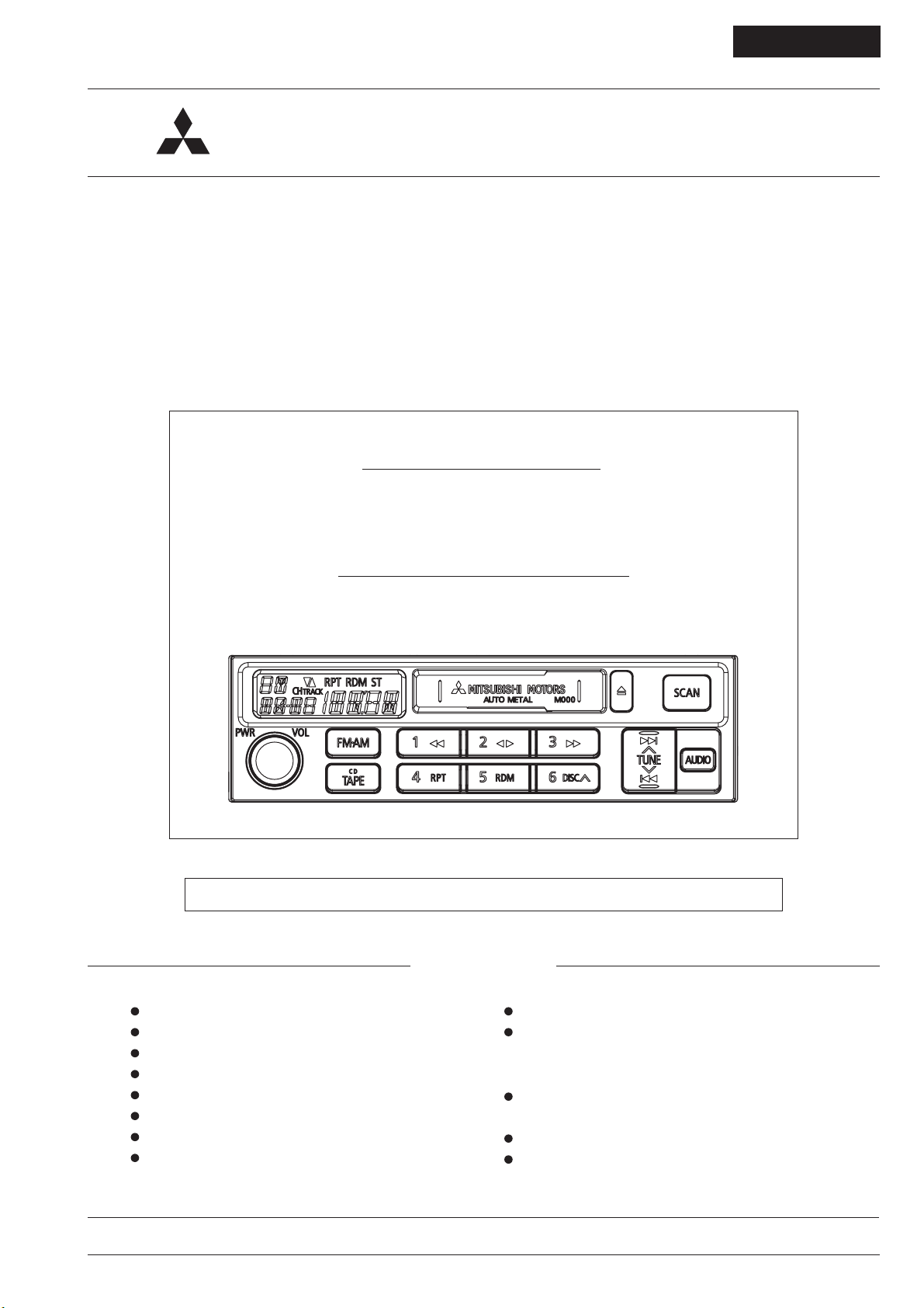
AM/FM-ST ELECTRONIC TUNING RADIO with CASSETTE
and CD PLAYER / CD CHANGER CONTROLLER
Model : RX-1MX8-T
PART No. : 8701A209
MELCO CODE : 34M140
2007 AUG.
Model : RX-1MX8-MT-T
PART No. : 8701A209
MELCO CODE : 349308
For the mecha part, please refer to the service manual of G-MECHA(955511) (2007 JUN.).
CONTENTS
FEATURES and SPECIFICATIONS .................. 2
OPERATION ................................................... 3,4
CONNECTORS .................................................. 4
BLOCK DIAGRAM .............................................. 5
SYSTEM CONFIGURATION .............................. 5
DISASSEMBLING PROCEDURES ................. 6,7
EXPLODED VIEW and PARTS LIST ................. 8
IC EXPLANATION ......................................... 9,10
ELECTRICAL PARTS LIST ......................... 11,12
PARTS LAYOUT ON PRINTED CIRCUIT BOARD
PCB-MAIN ............................................... 13,14
PCB-PANEL .................................................. 15
SCHEMATIC DIAGRAM
PCB-MAIN,PANEL .................................. 16~20
VOLTAGE ........................................................ 21
WAVEFORM .................................................... 22
SE017207073E
MITSUBISHI ELECTRIC CORP. SANDA WORKS
Copyright (c) Mitsubishi Electric Corporation

FEATURES and SPECIFICATIONS
FEATURES
Audio Part
High power, 4 channel outputs. (4 load)
Adjustment of BASS, TREBLE, BALANCE and FADER by
the Audio button.
Auto loudness to change the frequency response accord-
ing to volume level.
Radio
AM can preset the 6 stations and FM can preset the 6 sta-
tions.
The double function (auto and manual searching) button to
tune.
Scan function. (Searching available stations and receiving
it 5 seconds one by one.)
SD-WIDE Seek in AM.
Tape Player
The logic control mechanism by microcomputer. (G-
MECHA)
Power Eject function. (manual loading)
Auto tape type detection metal (high position) and normal
(not indicator).
Auto program sensor(APS) (maximum number -6 ~ +7)
during both forward and reverse playingback.
Repeat play of one program.
Any Time Eject function. (Eject at the all mode included
ACC OFF.)
Others
CD Changer (6 discs or 10 discs), In dash CD changer (4
discs or 6 discs) controls.
Disc Select, Track Select, Fast Forward / Fast Backward
function, Play mode Select (Normal, Repeat, Random and
Scan).
CD Player controls.
Track Select, Fast Forward / Fast Backward function, Play
mode Select (Normal, Repeat, Random and Scan).
M-BUS method to communicate with external CD Changer,
In dash CD Changer and CD Player.
Scan function. (Playing back top 10 seconds of all tracks
one by one.)
A liquid crystal display (LCD, positive type), which has
good visibility.
Beep (high-pitch tone for 40 msec) sounds to check opera-
tion by long pressing button during the audio adjustment
mode.
The luminosity of an LCD falls automatically just as the
lighting of a vehicle is put on.
Rheostat function. (The intensity of buttons, panel and
LCD can adjust to link with the intensity of vehicle's instru-
ment panel lighting.)
The connections of speakers wiring can be checked by
test mode of the beep in the vehicle's assembly line.
Inclined installation angle : 20 ±
15
SPECIFICATIONS
AM Radio
Frequency Range : 531 ~ 1629kHz (1kHz step)
Intermediate Frequency : 450kHz
Sensitivity (6dB S/N) : Less than 15dB
FM Stereo Radio
Frequency Range : 87.5 ~ 108.0MHz (25kHz step)
Intermediate Frequency : 10.7MHz
Limiting Sensitivity : Less than 10dB
Channel Separation : More than 12dB
(Input 40dBµV)
Tape Player
Reproduction System : 4-Track, 2-Program Stereo
Tape Speed : 4.76 cm / sec.
Wow and Flutter : Less than 0.18% (WRMS)
Signal/Noise Ratio : More than 48dB
Cross-talk : More than 50dB
Separation : More than 40dB
Others
Power Supply : DC 12V (11~16V)
Test Voltage 13.2V
Negative ground
Battery Back Up Current : Less than 1.0mA ± 20%
Current Consumption : ACC 2.3A ± 20% (Output 1W)
Maximum Power Output : 45W x 4 (4 load)
Output Impedance : 4 (SP Output)
Dimensions : 183(W) x 169(D) x 52(H)mm
Weight : 1.27kg
2
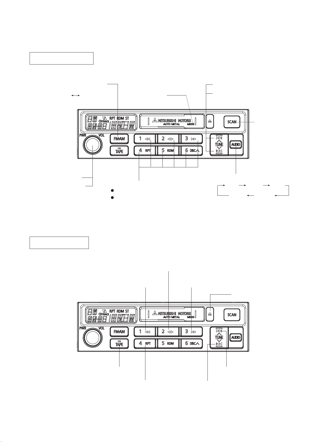
OPERATION
RADIO & AUDIO PART
Radio ON Button and
Band Select Button
(AM
Power Switch
Volume Control
(Endless)
FM)
ID Code
Memory and Preset Channel Button
Preset : Press for 0.5 seconds.
Memory : Press for 1.5 seconds or more.
Auto Tune UP/DOWN Button
Audio Adjustment UP/DOWN Button
Radio Scan Button
Audio Adjustment Mode Select Button
Bass Treble Fader
Cancel
Balance
TAPE PLAYER PART
Tape Mode Button
Repeat ON/OFF Button
Running Direction Changeover Button
Rewind Button
Fast Forward Button
Tape Eject Button
Fast Forward Automatic Program
Sensor (F-APS) Button
Rewind Automatic Program
Sensor (APS) Button
3
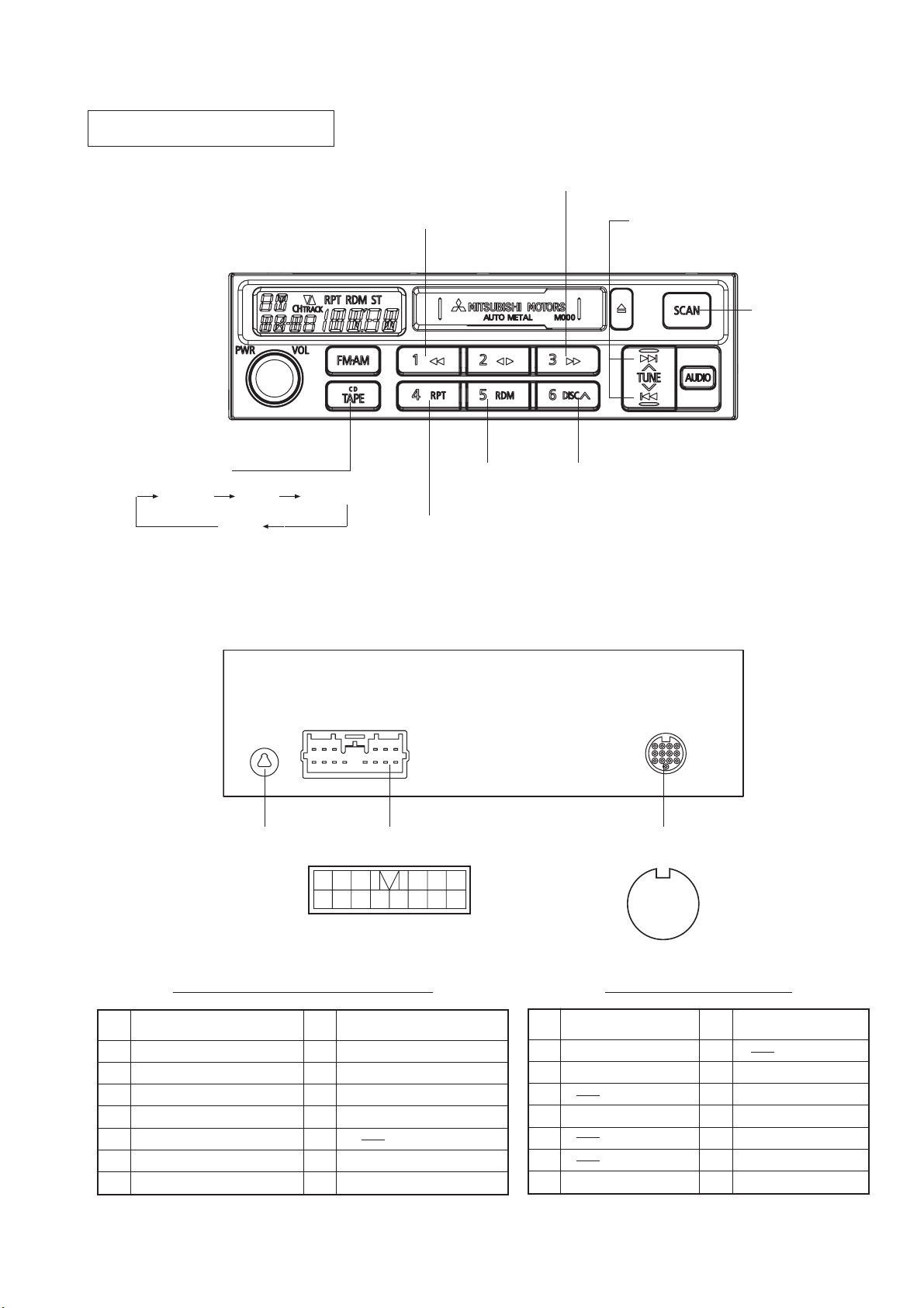
CD Player / CD Changer PART
Fast Forward Button
CD Mode Button
(TAPE) CD-P In dash CD-C
CD-C
CONNECTORS
Fast Backward Button
Random
ON/OFF Button
Repeat ON/OFF Button
Track Select UP/DOWN Button
Scan Button
CD-C Disc Select UP Button
Antenna Socket
Pin
No.
Name
1 Speaker FR (+)
2 Speaker FL (+)
3 Illumination (+)
4 Antenna + B
5 Speaker RL (+)
6 Speaker RR (+)
7 Speaker FR (_)
Power supply / Speaker
14P Connector
6
141312 1110 9 8
Pin
No.
Name
12345
7
8 Speaker FL (_)
9 Illumination (_)
10 Battery (+)
11 Accessory (+)
12
13 Speaker RL (_)
14 Speaker RR (_)
CD Changer
13P DIN Socket
H
1
23
4
6
5
7
8
12 1110 9
13
CD Changer 13P DIN SocketPower supply / Speaker 14P Connector
Pin
No.
1 SIG GND
2 Lch
3
4 Rch
5
6
7 ACC (+)
Name
Pin
No.
Name
8
9 Battery (+)
10 ILL LEVEL
11 M-BUSY
12 M-SCK
13 M-DATA
H SHIELD EARTH
4
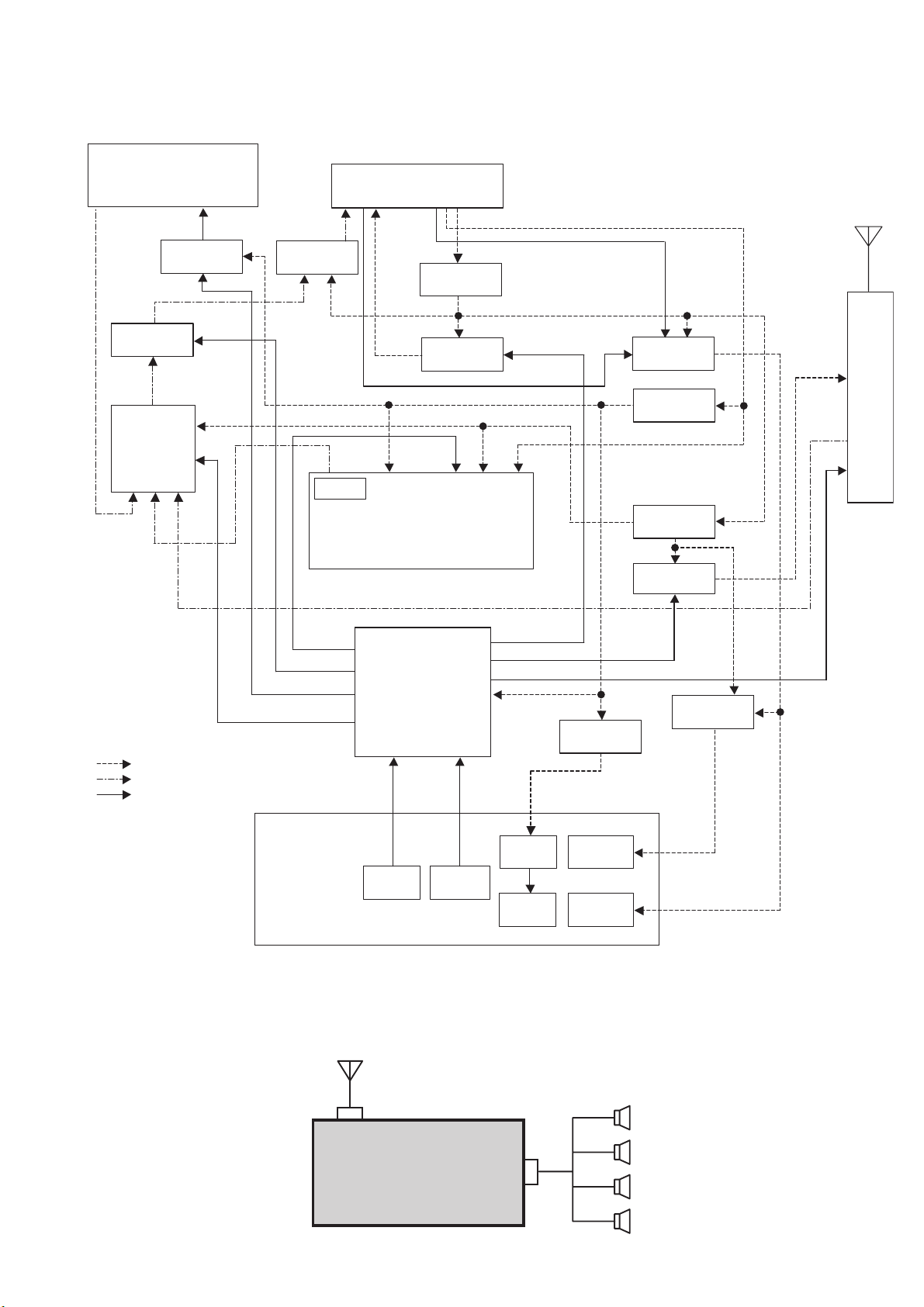
BLOCK DIAGRAM
J801
P891
1. SIG-GND
2. Lch
3. N.C.
MUTE CIRCUIT
IC301
ELECTRONIC
4. Rch
5. N.C.
VOLUME
6. N.C.
7. ACC
8. N.C.
9. BATT
10. LAMP Vcc
M-BUS BUFFER
11. M- BUSY
12. M-SCK
13. M-DATA
1. FR+
2. FL+
3. I LL+
4. A NT+
5. R L+
6. R R+
7. FR-
8. FL-
9. I LL-
10. BATT
11. ACC
12. N.C.
13. RL-
14. RR-
IC8B1
POWER-IC
L890
FILTER CIRCUIT
Q891
ANTENNA
POWER
Q852
BUTTON
ILLUMINATION
CIRCUIT
Q801
G-MECHA
1. SIG-GND
2. L ch
3. R ch
BATT 5V
POWER SUPPLY
Q8E0
ACC 9V
POWER SUPPLY
4. G ND
5. 9 V
6. B ATT
7. EN D-L
8. B LANK
9. EN D-R
10. M3/FF
11. M2/PLAY
12. M1/DOLBY
13. PKIN/MTL
14. M0/MTL
15. POWER
16. MMON
17. PMCW
18 . PMCCW
Q1
AM/FM
POWER SUPPLY
TUNER
FE101
IC801
POWER LINE
SIGNAL LINE
CONTROL LINE
PANEL
SYSTEM CONFIGURATION
MAIN ANTENNA
MICROCOMPUTER
VOLUME
CONTROL
ENCODER
VR901
OPERATION
KEY
SWITCH
IC901
LCD
DRIVER
LCD
DISPLAY
LCD9 01
Q810
ACC 5V
POWER SUPPLY
LCD
ILLUMINATION
BUTTON
ILLUMINATION
SPEAKER
FR
LCD
ILLUMINATION
CIRCUIT
Q857
AUDIO UNIT
RX-1MX8-T
RX-1MX8-MT-T
14P
FL
RL
RR
5
DISASSEMBLING PROCEDURES
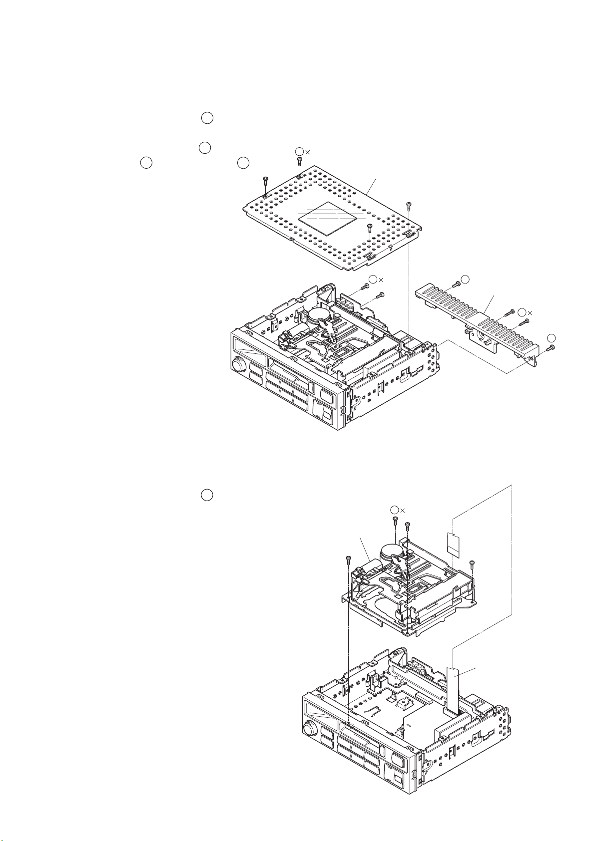
1. Removal of COVER, HEAT-SINK (See Fig.1)
1) Unscrew the four screws ( 1 ).
2) Remove the COVER.
3) Unscrew the two screws ( 2 ),
two screws ( 3 ) and two screws ( 4 ).
4) Remove the HEAT-SINK.
1
4(A)
COVER
2. Removal of G-MECHA (See Fig.2)
1) Unscrew the four screws ( 5 ).
2) Remove the FLAT-CABLE 19P.
3) Remove the G-MECHA.
G-MECHA
4
2(A)
(A)
3
HEAT-SINK
2
2(C)
(A)
3
Fig.1
5
4(A)
FLAT-CABLE 19P
Fig.2
6
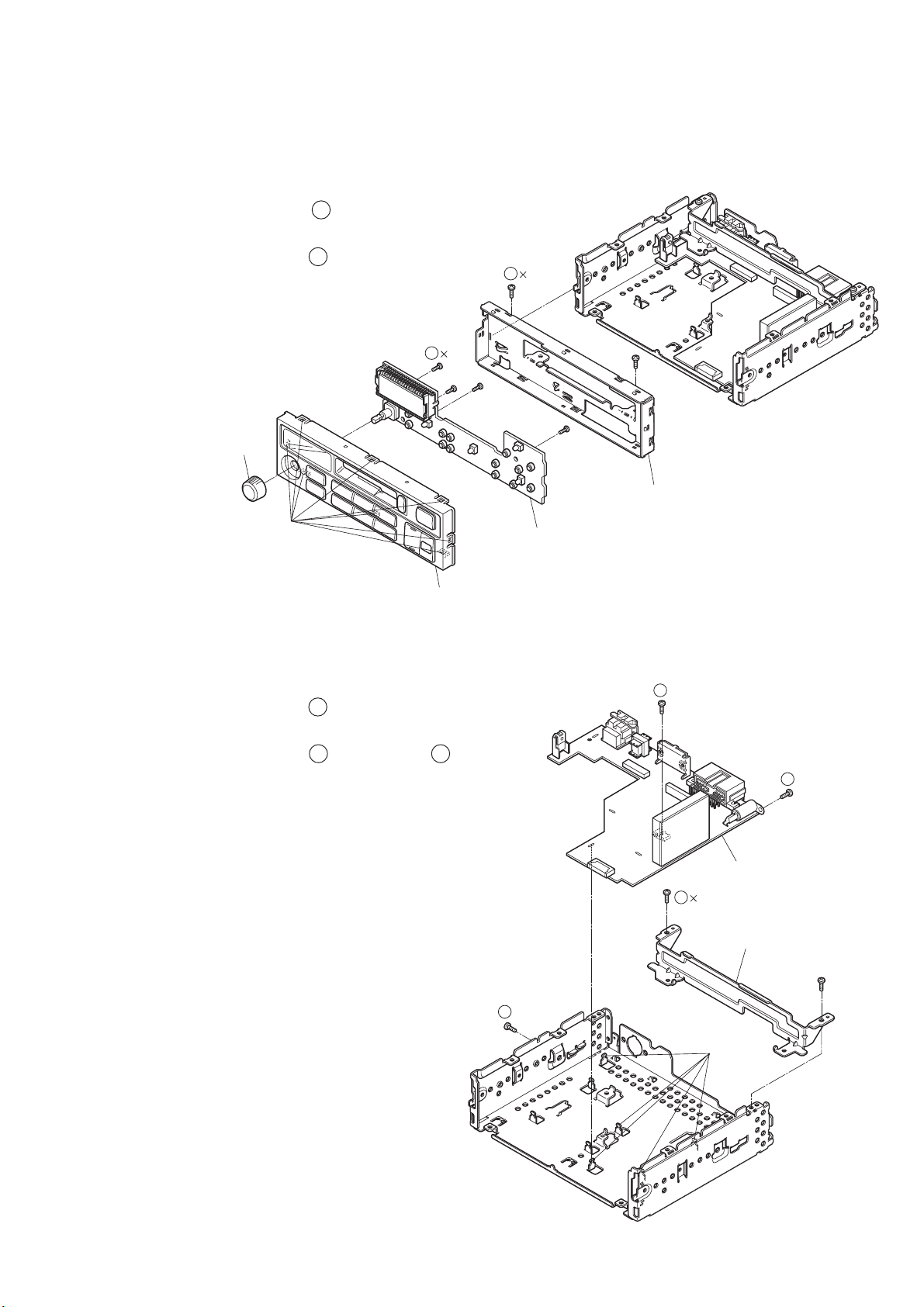
3. Removal of ASSY-PANEL, PCB-PANEL (See Fig.3)
1) Unlatch the eight hooks ( a ).
2) Remove the ASSY-PANEL.
3) Unscrew the four screws ( 6 ), remove the KNOB-VOL.
4) Remove the PCB-PANEL.
5) Unscrew the two screws ( 7 ).
6) Remove the CHASSIS-F.
6
4(D)
KNOB-VOL
7
2(A)
CHASSIS-F
(a)
4. Removal of PCB-MAIN (See Fig.4)
1) Unscrew the two screws ( 8 ).
2) Remove the BRACKET-DECK.
3) Unscrew the two screws ( 9 ), one screw ( 10 ).
4) Unlatch the five hooks ( b ).
5) Remove the PCB-MAIN.
ASSY-PANEL
PCB-PANEL
Fig.3
9
(A)
9
(A)
PCB-MAIN
8
2(A)
BRACKET-DECK
10
(B)
(b)
Fig.4
7
 Loading...