

Mitsubishi RM50HG-12S Datasheet
RM50HG-12S
MITSUBISHI FAST RECOVERY DIODE MODULES
RM50HG-12S
HIGH SPEED SWITCHING USE
NON-INSULATED TYPE
• IDC DC current .................................. 50A
• V
RRM Repetitive peak reverse voltage
................ 600V
• t
rr Reverse recovery time .............0.2µs
• ONE ARM
• Non-Insulated Type
APPLICATION
For snubber circuit (IPM or IGBT module)
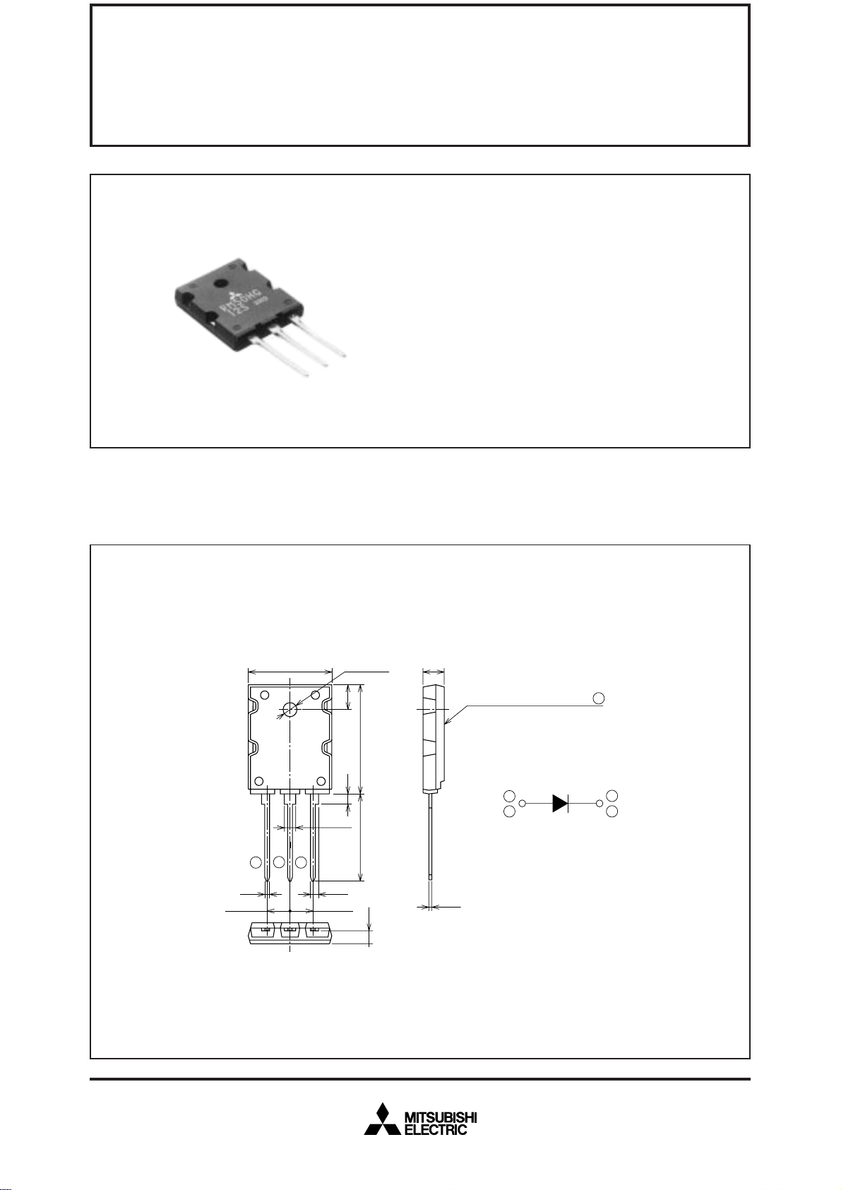
OUTLINE DRAWING & CIRCUIT DIAGRAM Dimensions in mm
5±0.3
Non-Isolation side (metal)
1
3
0.6±
0.2
4
2
4
1
1±0.2
5.45±0.5
20.5MAX.
2
3
2.5±0.3
2±0.3
5.45±0.5
φ3.2±
6±0.2
26±0.5
2.5
20MIN.
0.2
3±0.3
Feb.1999
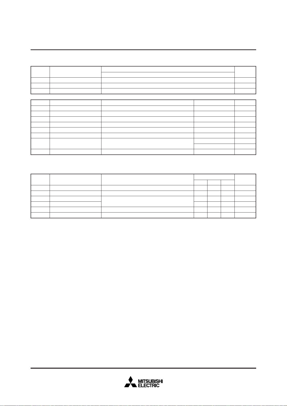
ABSOLUTE MAXIMUM RATINGS (Tj=25°C)
Symbol
RRM
V
VDRM
VR (DC)
Repetitive peak reverse voltage
Non-repetitive peak reverse voltage
Reverse DC voltage
Parameter
MITSUBISHI FAST RECOVERY DIODE MODULES
RM50HG-12S
HIGH SPEED SWITCHING USE
NON-INSULATED TYPE
Voltage class
12
600
720
480
Unit
V
V
V
Symbol
DC
I
IFSM
2
t
I
Tj
Tstg
Viso
DC current
Surge (non-repetitive) forward current
2
t
I
Junction temperature
Storage temperature
Isolation voltage
—
Mounting torque
—
Weight
Parameter
for fusing
ELECTRICAL CHARACTERISTICS
Symbol
I
RRM
VFM
trr
Qrr
Rth (j-c)
Rth (c-f)
Repetitive reverse current
Forward voltage
Reverse recovery time
Reverse recovery charge
Thermal resistance
Contact thermal resistance
Parameter
Conditions
Resistive load, T
One half cycle at 60Hz, peak value ➀, ➂ Collective of terminal
Value for one cycle surge current
Charged part to case
Mounting screw M3
Typical value
T
j=25/125°C, VRRM applied
j=25°C, IFM=200A, Instantaneous meas.
T
I
FM=200A, Tj=150°C, di/dt=–1000A/µs, VR=300V
Junction to case
Case to fin, conductive grease applied
C=80°C ➀, ➂ Collective of terminal
Test conditions
Min.
—
—
—
—
—
—
Ratings
50
1000
—
–40~+150
–40~+125
—
0.59~0.98
6~10
5
Limits
Typ.
—
—
—
—
—
—
Max.
0.1/1.0
4.0
0.2
—
0.5
0.5
Unit
A
A
2
A
°C
°C
V
N·m
kg·cm
g
Unit
mA
V
µs
µC
°C/W
°C/W
s
Feb.1999
 Loading...