


MELSEC iQ-R Digital-Analog Converter Module
User's Manual (Application)
-R60DA4
-R60DAV8
-R60DAI8

SAFETY PRECAUTIONS
WARNING
Indicates that incorrect handling may cause hazardous conditions, resulting in
death or severe injury.
CAUTION
Indicates that incorrect handling may cause hazardous conditions, resulting in
minor or moderate injury or property damage.
(Read these precautions before using this product.)
Before using this product, please read this manual and the relevant manuals carefully and pay full attention to safety to handle
the product correctly.
The precautions given in this manual are concerned with this product only. For the safety precautions of the programmable
controller system, refer to the MELSEC iQ-R Module Configuration Manual.
In this manual, the safety precautions are classified into two levels: " WARNING" and " CAUTION".
Under some circumstances, failure to observe the precautions given under " CAUTION" may lead to serious
consequences.
Observe the precautions of both levels because they are important for personal and system safety.
Make sure that the end users read this manual and then keep the manual in a safe place for future reference.
1

[Design Precautions]
WARNING
● Configure safety circuits external to the programmable controller to ensure that the entire system
operates safely even when a fault occurs in the external power supply or the programmable controller.
Failure to do so may result in an accident due to an incorrect output or malfunction.
(1) Emergency stop circuits, protection circuits, and protective interlock circuits for conflicting
operations (such as forward/reverse rotations or upper/lower limit positioning) must be configured
external to the programmable controller.
(2) When the programmable controller detects an abnormal condition, it stops the operation and all
outputs are:
• Turned off if the overcurrent or overvoltage protection of the power supply module is activated.
• Held or turned off according to the parameter setting if the self-diagnostic function of the CPU
module detects an error such as a watchdog timer error.
(3) All outputs may be turned on if an error occurs in a part, such as an I/O control part, where the
CPU module cannot detect any error. To ensure safety operation in such a case, provide a safety
mechanism or a fail-safe circuit external to the programmable controller. For a fail-safe circuit
example, refer to "General Safety Requirements" in the MELSEC iQ-R Module Configuration
Manual.
(4) Outputs may remain on or off due to a failure of a component such as a relay and transistor in an
output circuit. Configure an external circuit for monitoring output signals that could cause a
serious accident.
● In an output circuit, when a load current exceeding the rated current or an overcurrent caused by a
load short-circuit flows for a long time, it may cause smoke and fire. To prevent this, configure an
external safety circuit, such as a fuse.
● Configure a circuit so that the programmable controller is turned on first and then the external power
supply. If the external power supply is turned on first, an accident may occur due to an incorrect output
or malfunction.
● For the operating status of each station after a communication failure, refer to manuals relevant to the
network. Incorrect output or malfunction due to a communication failure may result in an accident.
● When connecting an external device with a CPU module or intelligent function module to modify data
of a running programmable controller, configure an interlock circuit in the program to ensure that the
entire system will always operate safely. For other forms of control (such as program modification,
parameter change, forced output, or operating status change) of a running programmable controller,
read the relevant manuals carefully and ensure that the operation is safe before proceeding. Improper
operation may damage machines or cause accidents.
● Especially, when a remote programmable controller is controlled by an external device, immediate
action cannot be taken if a problem occurs in the programmable controller due to a communication
failure. To prevent this, configure an interlock circuit in the program, and determine corrective actions
to be taken between the external device and CPU module in case of a communication failure.
● Do not write any data to the "system area" and "write-protect area" of the buffer memory in the
module. Also, do not use any "use prohibited" signals as an output signal from the CPU module to
each module. Doing so may cause malfunction of the programmable controller system. For the
"system area", "write-protect area", and the "use prohibited" signals, refer to the user's manual for the
module used.
2
[Design Precautions]
WARNING
● If a communication cable is disconnected, the network may be unstable, resulting in a communication
failure of multiple stations. Configure an interlock circuit in the program to ensure that the entire
system will always operate safely even if communications fail. Incorrect output or malfunction due to a
communication failure may result in an accident.
● To maintain the safety of the programmable controller system against unauthorized access from
external devices via the network, take appropriate measures. To maintain the safety against
unauthorized access via the Internet, take measures such as installing a firewall.
● Analog outputs may remain on due to a failure of the module. Configure an external interlock circuit
for output signals that could cause a serious accident.
[Design Precautions]
CAUTION
● Do not install the control lines or communication cables together with the main circuit lines or power
cables. Keep a distance of 100mm or more between them. Failure to do so may result in malfunction
due to noise.
● During control of an inductive load such as a lamp, heater, or solenoid valve, a large current
(approximately ten times greater than normal) may flow when the output is turned from off to on.
Therefore, use a module that has a sufficient current rating.
● After the CPU module is powered on or is reset, the time taken to enter the RUN status varies
depending on the system configuration, parameter settings, and/or program size. Design circuits so
that the entire system will always operate safely, regardless of the time.
● Do not power off the programmable controller or reset the CPU module while the setting values in the
buffer memory are being written to the flash ROM in the module. Doing so will make the data in the
flash ROM undefined. The values need to be set in the buffer memory and written to the flash ROM
again. Doing so also can cause malfunction or failure of the module.
● When changing the operating status of the CPU module (such as remote RUN/STOP) from the
external device, select "Do Not OPEN in Program" for the "Open Method Setting" in the module
parameter. The communication line will be closed when "OPEN in Program" is selected and the
remote STOP is executed from the external device. Consequently, the CPU module cannot reopen
the communication line, and the external device cannot execute the remote RUN.
● Power on or off the external power supply while the programmable controller is on. Failure to do so
may result in incorrect output or malfunction.
● At on/off of the power or external power supply, or at the output range switching, a voltage may occur
or a current may flow between output terminals for a moment. In this case, start the control after
analog outputs become stable.
3
[Installation Precautions]
WARNING
● Shut off the external power supply (all phases) used in the system before mounting or removing the
module. Failure to do so may result in electric shock or cause the module to fail or malfunction.
[Installation Precautions]
CAUTION
● Use the programmable controller in an environment that meets the general specifications in the Safety
Guidelines included with the base unit. Failure to do so may result in electric shock, fire, malfunction,
or damage to or deterioration of the product.
● To mount a module, place the concave part(s) located at the bottom onto the guide(s) of the base unit,
and push in the module until the hook(s) located at the top snaps into place. Incorrect interconnection
may cause malfunction, failure, or drop of the module.
● When using the programmable controller in an environment of frequent vibrations, fix the module with
a screw.
● Tighten the screws within the specified torque range. Undertightening can cause drop of the screw,
short circuit, or malfunction. Overtightening can damage the screw and/or module, resulting in drop,
short circuit, or malfunction.
● When using an extension cable, connect it to the extension cable connector of the base unit securely.
Check the connection for looseness. Poor contact may cause malfunction.
● When using an SD memory card, fully insert it into the SD memory card slot. Check that it is inserted
completely. Poor contact may cause malfunction. / Failure to do so may cause malfunction.
● Securely insert an extended SRAM cassette into the cassette connector of the CPU module. After
insertion, close the cassette cover and check that the cassette is inserted completely. Poor contact
may cause malfunction.
● Do not directly touch any conductive parts and electronic components of the module, SD memory
card, extended SRAM cassette, or connector. Doing so can cause malfunction or failure of the
module.
[Wiring Precautions]
WARNING
● Shut off the external power supply (all phases) used in the system before installation or wiring. Failure
to do so may result in electric shock or cause the module to fail or malfunction.
● After installation and wiring, attach the included terminal cover to the module before turning it on for
operation. Failure to do so may result in electric shock.
4

[Wiring Precautions]
CAUTION
● Individually ground the FG and LG terminals of the programmable controller with a ground resistance
of 100 ohms or less. Failure to do so may result in electric shock or malfunction.
● Use applicable solderless terminals and tighten them within the specified torque range. If any spade
solderless terminal is used, it may be disconnected when the terminal screw comes loose, resulting in
failure.
● Check the rated voltage and signal layout before wiring to the module, and connect the cables
correctly. Connecting a power supply with a different voltage rating or incorrect wiring may cause fire
or failure.
● Connectors for external devices must be crimped or pressed with the tool specified by the
manufacturer, or must be correctly soldered. Incomplete connections may cause short circuit, fire, or
malfunction.
● Securely connect the connector to the module. Poor contact may cause malfunction.
● Do not install the control lines or communication cables together with the main circuit lines or power
cables. Keep a distance of 100mm or more between them. Failure to do so may result in malfunction
due to noise.
● Place the cables in a duct or clamp them. If not, dangling cable may swing or inadvertently be pulled,
resulting in damage to the module or cables or malfunction due to poor contact. Do not clamp the
extension cables with the jacket stripped. Doing so may change the characteristics of the cables,
resulting in malfunction.
● Check the interface type and correctly connect the cable. Incorrect wiring (connecting the cable to an
incorrect interface) may cause failure of the module and external device.
● Tighten the terminal screws or connector screws within the specified torque range. Undertightening
can cause drop of the screw, short circuit, fire, or malfunction. Overtightening can damage the screw
and/or module, resulting in drop, short circuit, fire, or malfunction.
● When disconnecting the cable from the module, do not pull the cable by the cable part. For the cable
with connector, hold the connector part of the cable. For the cable connected to the terminal block,
loosen the terminal screw. Pulling the cable connected to the module may result in malfunction or
damage to the module or cable.
● Prevent foreign matter such as dust or wire chips from entering the module. Such foreign matter can
cause a fire, failure, or malfunction.
● A protective film is attached to the top of the module to prevent foreign matter, such as wire chips,
from entering the module during wiring. Do not remove the film during wiring. Remove it for heat
dissipation before system operation.
● Mitsubishi programmable controllers must be installed in control panels. Connect the main power
supply to the power supply module in the control panel through a relay terminal block. Wiring and
replacement of a power supply module must be performed by qualified maintenance personnel with
knowledge of protection against electric shock. For wiring, refer to the MELSEC iQ-R Module
Configuration Manual.
● For Ethernet cables to be used in the system, select the ones that meet the specifications in the user's
manual for each module. If not, normal data transmission is not guaranteed.
5

[Startup and Maintenance Precautions]
Warning
● Do not touch any terminal while power is on. Doing so will cause electric shock or malfunction.
● Correctly connect the battery connector. Do not charge, disassemble, heat, short-circuit, solder, or
throw the battery into the fire. Also, do not expose it to liquid or strong shock. Doing so will cause the
battery to produce heat, explode, ignite, or leak, resulting in injury and fire.
● Shut off the external power supply (all phases) used in the system before cleaning the module or
retightening the terminal screws, connector screws, or module fixing screws. Failure to do so may
result in electric shock.
6

[Startup and Maintenance Precautions]
CAUTION
● When connecting an external device with a CPU module or intelligent function module to modify data
of a running programmable controller, configure an interlock circuit in the program to ensure that the
entire system will always operate safely. For other forms of control (such as program modification,
parameter change, forced output, or operating status change) of a running programmable controller,
read the relevant manuals carefully and ensure that the operation is safe before proceeding. Improper
operation may damage machines or cause accidents.
● Especially, when a remote programmable controller is controlled by an external device, immediate
action cannot be taken if a problem occurs in the programmable controller due to a communication
failure. To prevent this, configure an interlock circuit in the program, and determine corrective actions
to be taken between the external device and CPU module in case of a communication failure.
● Do not disassemble or modify the modules. Doing so may cause failure, malfunction, injury, or a fire.
● Use any radio communication device such as a cellular phone or PHS (Personal Handy-phone
System) more than 25cm away in all directions from the programmable controller. Failure to do so
may cause malfunction.
● Shut off the external power supply (all phases) used in the system before mounting or removing the
module. Failure to do so may cause the module to fail or malfunction.
● Tighten the screws within the specified torque range. Undertightening can cause drop of the
component or wire, short circuit, or malfunction. Overtightening can damage the screw and/or module,
resulting in drop, short circuit, or malfunction.
● After the first use of the product, do not mount/remove the module to/from the base unit, and the
terminal block to/from the module, and do not insert/remove the extended SRAM cassette to/from the
CPU module more than 50 times (IEC 61131-2 compliant) respectively. Exceeding the limit may cause
malfunction.
● After the first use of the product, do not insert/remove the SD memory card to/from the CPU module
more than 500 times. Exceeding the limit may cause malfunction.
● Do not touch the metal terminals on the back side of the SD memory card. Doing so may cause
malfunction.
● Do not touch the integrated circuits on the circuit board of an extended SRAM cassette. Doing so may
cause malfunction.
● Do not drop or apply shock to the battery to be installed in the module. Doing so may damage the
battery, causing the battery fluid to leak inside the battery. If the battery is dropped or any shock is
applied to it, dispose of it without using.
● Startup and maintenance of a control panel must be performed by qualified maintenance personnel
with knowledge of protection against electric shock. Lock the control panel so that only qualified
maintenance personnel can operate it.
● Before handling the module, touch a conducting object such as a grounded metal to discharge the
static electricity from the human body. Failure to do so may cause the module to fail or malfunction.
7
[Operating Precautions]
CAUTION
● When changing data and operating status, and modifying program of the running programmable
controller from an external device such as a personal computer connected to an intelligent function
module, read relevant manuals carefully and ensure the safety before operation. Incorrect change or
modification may cause system malfunction, damage to the machines, or accidents.
● Do not power off the programmable controller or reset the CPU module while the setting values in the
buffer memory are being written to the flash ROM in the module. Doing so will make the data in the
flash ROM undefined. The values need to be set in the buffer memory and written to the flash ROM
again. Doing so also can cause malfunction or failure of the module.
[Disposal Precautions]
CAUTION
● When disposing of this product, treat it as industrial waste.
● When disposing of batteries, separate them from other wastes according to the local regulations. For
details on battery regulations in EU member states, refer to the MELSEC iQ-R Module Configuration
Manual.
[Transportation Precautions]
CAUTION
● When transporting lithium batteries, follow the transportation regulations. For details on the regulated
models, refer to the MELSEC iQ-R Module Configuration Manual.
● The halogens (such as fluorine, chlorine, bromine, and iodine), which are contained in a fumigant
used for disinfection and pest control of wood packaging materials, may cause failure of the product.
Prevent the entry of fumigant residues into the product or consider other methods (such as heat
treatment) instead of fumigation. The disinfection and pest control measures must be applied to
unprocessed raw wood.
8

CONDITIONS OF USE FOR THE PRODUCT
(1) Mitsubishi programmable controller ("the PRODUCT") shall be used in conditions;
i) where any problem, fault or failure occurring in the PRODUCT, if any, shall not lead to any major or serious accident;
and
ii) where the backup and fail-safe function are systematically or automatically provided outside of the PRODUCT for the
case of any problem, fault or failure occurring in the PRODUCT.
(2) The PRODUCT has been designed and manufactured for the purpose of being used in general industries.
MITSUBISHI SHALL HAVE NO RESPONSIBILITY OR LIABILITY (INCLUDING, BUT NOT LIMITED TO ANY AND ALL
RESPONSIBILITY OR LIABILITY BASED ON CONTRACT, WARRANTY, TORT, PRODUCT LIABILITY) FOR ANY
INJURY OR DEATH TO PERSONS OR LOSS OR DAMAGE TO PROPERTY CAUSED BY the PRODUCT THAT ARE
OPERATED OR USED IN APPLICATION NOT INTENDED OR EXCLUDED BY INSTRUCTIONS, PRECAUTIONS, OR
WARNING CONTAINED IN MITSUBISHI'S USER, INSTRUCTION AND/OR SAFETY MANUALS, TECHNICAL
BULLETINS AND GUIDELINES FOR the PRODUCT.
("Prohibited Application")
Prohibited Applications include, but not limited to, the use of the PRODUCT in;
• Nuclear Power Plants and any other power plants operated by Power companies, and/or any other cases in which the
public could be affected if any problem or fault occurs in the PRODUCT.
• Railway companies or Public service purposes, and/or any other cases in which establishment of a special quality
assurance system is required by the Purchaser or End User.
• Aircraft or Aerospace, Medical applications, Train equipment, transport equipment such as Elevator and Escalator,
Incineration and Fuel devices, Vehicles, Manned transportation, Equipment for Recreation and Amusement, and
Safety devices, handling of Nuclear or Hazardous Materials or Chemicals, Mining and Drilling, and/or other
applications where there is a significant risk of injury to the public or property.
Notwithstanding the above restrictions, Mitsubishi may in its sole discretion, authorize use of the PRODUCT in one or
more of the Prohibited Applications, provided that the usage of the PRODUCT is limited only for the specific
applications agreed to by Mitsubishi and provided further that no special quality assurance or fail-safe, redundant or
other safety features which exceed the general specifications of the PRODUCTs are required. For details, please
contact the Mitsubishi representative in your region.
9

INTRODUCTION
Thank you for purchasing the Mitsubishi Electric MELSEC iQ-R series programmable controllers.
This manual describes the functions, parameter settings, and troubleshooting of the relevant products listed below.
Before using this product, please read this manual and the relevant manuals carefully and develop familiarity with the
functions and performance of the MELSEC iQ-R series programmable controller to handle the product correctly.
When applying the program examples provided in this manual to an actual system, ensure the applicability and confirm that it
will not cause system control problems.
Please make sure that the end users read this manual.
Unless otherwise specified, this manual describes the program examples in which the I/O numbers of X/Y0 to
X/YF are assigned for a D/A converter module. I/O numbers must be assigned to apply the program examples
introduced in this manual to an actual system. For I/O number assignment, refer to the following.
MELSEC iQ-R CPU Module User's Manual (Application)
Relevant products
R60DA4. R60DAV8, R60DAI8
10

MEMO
11

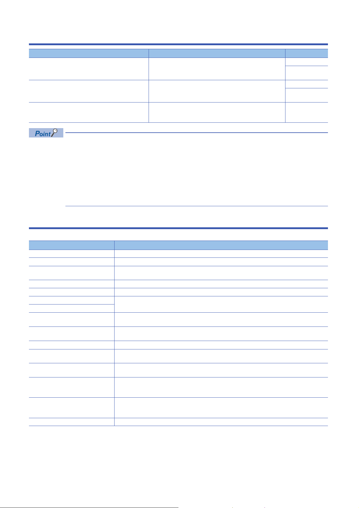
CONTENTS
SAFETY PRECAUTIONS . . . . . . . . . . . . . . . . . . . . . . . . . . . . . . . . . . . . . . . . . . . . . . . . . . . . . . . . . . . . . . . . . . . .1
CONDITIONS OF USE FOR THE PRODUCT . . . . . . . . . . . . . . . . . . . . . . . . . . . . . . . . . . . . . . . . . . . . . . . . . . . .9
INTRODUCTION. . . . . . . . . . . . . . . . . . . . . . . . . . . . . . . . . . . . . . . . . . . . . . . . . . . . . . . . . . . . . . . . . . . . . . . . . .10
RELEVANT MANUALS . . . . . . . . . . . . . . . . . . . . . . . . . . . . . . . . . . . . . . . . . . . . . . . . . . . . . . . . . . . . . . . . . . . . .14
TERMS . . . . . . . . . . . . . . . . . . . . . . . . . . . . . . . . . . . . . . . . . . . . . . . . . . . . . . . . . . . . . . . . . . . . . . . . . . . . . . . . .14
CHAPTER 1 FUNCTIONS 15
1.1 Modes . . . . . . . . . . . . . . . . . . . . . . . . . . . . . . . . . . . . . . . . . . . . . . . . . . . . . . . . . . . . . . . . . . . . . . . . . . . . . . . . .16
1.2 Range Switching Function . . . . . . . . . . . . . . . . . . . . . . . . . . . . . . . . . . . . . . . . . . . . . . . . . . . . . . . . . . . . . . . .18
1.3 D/A Conversion Enable/Disable Function . . . . . . . . . . . . . . . . . . . . . . . . . . . . . . . . . . . . . . . . . . . . . . . . . . . . 19
1.4 D/A Output Enable/Disable Setting Function . . . . . . . . . . . . . . . . . . . . . . . . . . . . . . . . . . . . . . . . . . . . . . . . .19
1.5 Analog Output HOLD/CLEAR Function. . . . . . . . . . . . . . . . . . . . . . . . . . . . . . . . . . . . . . . . . . . . . . . . . . . . . .20
1.6 Analog Output Test when CPU Module is in STOP Status Function . . . . . . . . . . . . . . . . . . . . . . . . . . . . . . 22
1.7 Scaling Function . . . . . . . . . . . . . . . . . . . . . . . . . . . . . . . . . . . . . . . . . . . . . . . . . . . . . . . . . . . . . . . . . . . . . . . .23
1.8 Shift Function . . . . . . . . . . . . . . . . . . . . . . . . . . . . . . . . . . . . . . . . . . . . . . . . . . . . . . . . . . . . . . . . . . . . . . . . . . 26
1.9 Alert Output Function . . . . . . . . . . . . . . . . . . . . . . . . . . . . . . . . . . . . . . . . . . . . . . . . . . . . . . . . . . . . . . . . . . . . 28
1.10 Rate Control Function. . . . . . . . . . . . . . . . . . . . . . . . . . . . . . . . . . . . . . . . . . . . . . . . . . . . . . . . . . . . . . . . . . . .30
1.11 External Power Supply Disconnection Detection Function . . . . . . . . . . . . . . . . . . . . . . . . . . . . . . . . . . . . . 33
1.12 Disconnection Detection Function . . . . . . . . . . . . . . . . . . . . . . . . . . . . . . . . . . . . . . . . . . . . . . . . . . . . . . . . .34
1.13 Interrupt Function . . . . . . . . . . . . . . . . . . . . . . . . . . . . . . . . . . . . . . . . . . . . . . . . . . . . . . . . . . . . . . . . . . . . . . .35
1.14 Wave Output Function . . . . . . . . . . . . . . . . . . . . . . . . . . . . . . . . . . . . . . . . . . . . . . . . . . . . . . . . . . . . . . . . . . . 38
Initial settings of the wave output function. . . . . . . . . . . . . . . . . . . . . . . . . . . . . . . . . . . . . . . . . . . . . . . . . . . . . .46
Execution of the wave output function. . . . . . . . . . . . . . . . . . . . . . . . . . . . . . . . . . . . . . . . . . . . . . . . . . . . . . . . .52
Points to use the wave output function . . . . . . . . . . . . . . . . . . . . . . . . . . . . . . . . . . . . . . . . . . . . . . . . . . . . . . . .64
Wave output step action function . . . . . . . . . . . . . . . . . . . . . . . . . . . . . . . . . . . . . . . . . . . . . . . . . . . . . . . . . . . . 70
1.15 Inter-Module Synchronization Function . . . . . . . . . . . . . . . . . . . . . . . . . . . . . . . . . . . . . . . . . . . . . . . . . . . . . 78
1.16 Error History Function . . . . . . . . . . . . . . . . . . . . . . . . . . . . . . . . . . . . . . . . . . . . . . . . . . . . . . . . . . . . . . . . . . .84
1.17 Event History Function . . . . . . . . . . . . . . . . . . . . . . . . . . . . . . . . . . . . . . . . . . . . . . . . . . . . . . . . . . . . . . . . . . .87
1.18 Backing up, Saving, and Restoring Offset/Gain Values . . . . . . . . . . . . . . . . . . . . . . . . . . . . . . . . . . . . . . . . 88
When a module-specific backup parameters is used . . . . . . . . . . . . . . . . . . . . . . . . . . . . . . . . . . . . . . . . . . . . .88
When the module-specific backup parameter is not used. . . . . . . . . . . . . . . . . . . . . . . . . . . . . . . . . . . . . . . . . .90
1.19 Q Compatible Mode Function. . . . . . . . . . . . . . . . . . . . . . . . . . . . . . . . . . . . . . . . . . . . . . . . . . . . . . . . . . . . . .94
12
CHAPTER 2 PARAMETER SETTING 95
2.1 Basic Setting . . . . . . . . . . . . . . . . . . . . . . . . . . . . . . . . . . . . . . . . . . . . . . . . . . . . . . . . . . . . . . . . . . . . . . . . . . .95
2.2 Application Setting . . . . . . . . . . . . . . . . . . . . . . . . . . . . . . . . . . . . . . . . . . . . . . . . . . . . . . . . . . . . . . . . . . . . . . 96
2.3 Interrupt Setting. . . . . . . . . . . . . . . . . . . . . . . . . . . . . . . . . . . . . . . . . . . . . . . . . . . . . . . . . . . . . . . . . . . . . . . . .97
2.4 Refresh Settings . . . . . . . . . . . . . . . . . . . . . . . . . . . . . . . . . . . . . . . . . . . . . . . . . . . . . . . . . . . . . . . . . . . . . . . .98
Refresh processing time . . . . . . . . . . . . . . . . . . . . . . . . . . . . . . . . . . . . . . . . . . . . . . . . . . . . . . . . . . . . . . . . . . . 99
CHAPTER 3 TROUBLESHOOTING 100
3.1 Checking Using LEDs . . . . . . . . . . . . . . . . . . . . . . . . . . . . . . . . . . . . . . . . . . . . . . . . . . . . . . . . . . . . . . . . . . . 100
3.2 Checking the Status of the Module . . . . . . . . . . . . . . . . . . . . . . . . . . . . . . . . . . . . . . . . . . . . . . . . . . . . . . . . 101
3.3 Troubleshooting by Symptom . . . . . . . . . . . . . . . . . . . . . . . . . . . . . . . . . . . . . . . . . . . . . . . . . . . . . . . . . . . . 102
When the RUN LED flashes or turns off . . . . . . . . . . . . . . . . . . . . . . . . . . . . . . . . . . . . . . . . . . . . . . . . . . . . . . 102
When the ERR LED turns on. . . . . . . . . . . . . . . . . . . . . . . . . . . . . . . . . . . . . . . . . . . . . . . . . . . . . . . . . . . . . . .102
When the ALM LED turns on. . . . . . . . . . . . . . . . . . . . . . . . . . . . . . . . . . . . . . . . . . . . . . . . . . . . . . . . . . . . . . . 102
When an analog value is not output . . . . . . . . . . . . . . . . . . . . . . . . . . . . . . . . . . . . . . . . . . . . . . . . . . . . . . . . . 103

When an analog value is not output with the wave output function being selected. . . . . . . . . . . . . . . . . . . . . .104
When HOLD of analog output value is not available. . . . . . . . . . . . . . . . . . . . . . . . . . . . . . . . . . . . . . . . . . . . . 104
When the synchronization output is not performed . . . . . . . . . . . . . . . . . . . . . . . . . . . . . . . . . . . . . . . . . . . . . .105
When 'External power supply READY flag' (X7) does not turn on . . . . . . . . . . . . . . . . . . . . . . . . . . . . . . . . . . 105
3.4 Error Code List . . . . . . . . . . . . . . . . . . . . . . . . . . . . . . . . . . . . . . . . . . . . . . . . . . . . . . . . . . . . . . . . . . . . . . . .106
3.5 Alarm Code List. . . . . . . . . . . . . . . . . . . . . . . . . . . . . . . . . . . . . . . . . . . . . . . . . . . . . . . . . . . . . . . . . . . . . . . . 110
APPENDICES 111
Appendix 1 Module Label . . . . . . . . . . . . . . . . . . . . . . . . . . . . . . . . . . . . . . . . . . . . . . . . . . . . . . . . . . . . . . . . . . . . . 111
Appendix 2 I/O Signals . . . . . . . . . . . . . . . . . . . . . . . . . . . . . . . . . . . . . . . . . . . . . . . . . . . . . . . . . . . . . . . . . . . . . . . 113
List of I/O signals. . . . . . . . . . . . . . . . . . . . . . . . . . . . . . . . . . . . . . . . . . . . . . . . . . . . . . . . . . . . . . . . . . . . . . . . 113
Details of input signals. . . . . . . . . . . . . . . . . . . . . . . . . . . . . . . . . . . . . . . . . . . . . . . . . . . . . . . . . . . . . . . . . . . . 114
Details of output signals . . . . . . . . . . . . . . . . . . . . . . . . . . . . . . . . . . . . . . . . . . . . . . . . . . . . . . . . . . . . . . . . . .121
Appendix 3 Buffer Memory . . . . . . . . . . . . . . . . . . . . . . . . . . . . . . . . . . . . . . . . . . . . . . . . . . . . . . . . . . . . . . . . . . . .124
List of buffer memory addresses . . . . . . . . . . . . . . . . . . . . . . . . . . . . . . . . . . . . . . . . . . . . . . . . . . . . . . . . . . . .124
Details of buffer memory addresses . . . . . . . . . . . . . . . . . . . . . . . . . . . . . . . . . . . . . . . . . . . . . . . . . . . . . . . . .136
Appendix 4 Dedicated Instruction . . . . . . . . . . . . . . . . . . . . . . . . . . . . . . . . . . . . . . . . . . . . . . . . . . . . . . . . . . . . . .174
Instruction list. . . . . . . . . . . . . . . . . . . . . . . . . . . . . . . . . . . . . . . . . . . . . . . . . . . . . . . . . . . . . . . . . . . . . . . . . . . 174
Appendix 5 Operation Examples of When the Remote Head Module Is Mounted . . . . . . . . . . . . . . . . . . . . . . . .175
System configuration example . . . . . . . . . . . . . . . . . . . . . . . . . . . . . . . . . . . . . . . . . . . . . . . . . . . . . . . . . . . . .175
Setting in the master station . . . . . . . . . . . . . . . . . . . . . . . . . . . . . . . . . . . . . . . . . . . . . . . . . . . . . . . . . . . . . . .176
Setting in the intelligent device station . . . . . . . . . . . . . . . . . . . . . . . . . . . . . . . . . . . . . . . . . . . . . . . . . . . . . . .179
Checking the network status . . . . . . . . . . . . . . . . . . . . . . . . . . . . . . . . . . . . . . . . . . . . . . . . . . . . . . . . . . . . . . . 182
Program examples . . . . . . . . . . . . . . . . . . . . . . . . . . . . . . . . . . . . . . . . . . . . . . . . . . . . . . . . . . . . . . . . . . . . . . 182
Appendix 6 Added or Changed Functions. . . . . . . . . . . . . . . . . . . . . . . . . . . . . . . . . . . . . . . . . . . . . . . . . . . . . . . . 185
CONTENTS
INDEX 186
REVISIONS. . . . . . . . . . . . . . . . . . . . . . . . . . . . . . . . . . . . . . . . . . . . . . . . . . . . . . . . . . . . . . . . . . . . . . . . . . . . .188
WARRANTY . . . . . . . . . . . . . . . . . . . . . . . . . . . . . . . . . . . . . . . . . . . . . . . . . . . . . . . . . . . . . . . . . . . . . . . . . . . .189
TRADEMARK . . . . . . . . . . . . . . . . . . . . . . . . . . . . . . . . . . . . . . . . . . . . . . . . . . . . . . . . . . . . . . . . . . . . . . . . . . .190
13
RELEVANT MANUALS
Manual name [manual number] Description Available form
MELSEC iQ-R Digital-Analog Converter Module User's
Manual (Application)
[SH-081237ENG] (this manual)
MELSEC iQ-R Digital-Analog Converter Module User's
Manual (Startup)
[SH-081235ENG]
MELSEC iQ-R Programming Manual (Module Dedicated
Instructions)
[SH-081976ENG]
e-Manuals are electronic book-type manuals for Mitsubishi Electric FA products that can be read with a
dedicated tool.
The following shows the features of e-Manuals.
• Desired information can be searched for from multiple manuals at a time. (Manual cross search)
• Other manuals can be referred to from links in a manual.
• Desired hardware specifications can be checked from each part in the illustrations of products.
• Information frequently referred to can be registered as a favorite.
• Sample programs can be copied to an engineering tool.
Functions, parameter setting, troubleshooting, I/O signals, and buffer
memory of the D/A converter module
Specifications, procedures before operation, wiring, operatio n example,
and offset/gain setting of the D/A converter module
Dedicated instructions for the intelligent function modules e-Manual
Print book
e-Manual
PDF
Print book
e-Manual
PDF
PDF
TERMS
Unless otherwise specified, this manual uses the following terms.
Term Description
D/A converter module The abbreviation for the MELSEC iQ-R series digital-analog converter module
GX Works3 The product name of the software package for the MELSEC programmable controllers
Watchdog timer error An error that occurs if the internal processing of the D/A converter module is abnormal. Watchdog timer enables
Engineering tool A generic term for GX Works3
Factory default setting A generic term for analog output ranges of 0 to 10V, 0 to 5V, 1 to 5V, -10 to 10V, 0 to 20mA, and 4 to 20mA
Normal mode Setting values of the operation mode setting: normal mode and offset/gain setting mode
Offset/gain setting mode
Synchronization normal output mode When the inter-module synchronization function target is enabled, a value is set to CH Synchronization digital
Buffer memory A memory in an intelligent function module, where data (such as setting values and monitoring values)
User range An analog output range where any value can be set. Set the user range in the offset/gain setting.
R mode A mode that the module operates w ith the buffer memory map that memory areas have been newly laid out in the
Q compatible mode A mode that the module operates with the buffer memory map converted to the equivalent map of the MELSEC-
Global label A label that is valid for all program data created in the project. The global label has two types: a module specific
Module label A label that represents a memory (I/O signals and buffer memory areas) specific to each module in a given
Remote head module The abbreviation for the RJ72GF15-T2 CC-Link IE Field Network remote head module
the module to monitor its own internal processing.
value using a synchronous interrupt program and the value is output on the set synchronization cycle.
exchanged with a CPU module are stored
MELSEC iQ-R series.
Q series.
label (module label) generated automatically by GX Works3, and an optional label for which any device can be
specified.
character string. Through the module used, GX Works3 automatically generates this label, which can be used as
a global label.
14

1 FUNCTIONS
This chapter describes the functions of the D/A converter module and the setting procedures for those functions.
For details of the I/O signals and the buffer memory, refer to the following.
Page 114 Details of input signals
Page 121 Details of output signals
Page 136 Details of buffer memory addresses
• This chapter describes I/O signals and buffer memory addresses for CH1. For details on the I/O signals and
buffer memory addresses for CH2 or later, refer to the following.
Page 113 List of I/O signals
Page 124 List of buffer memory addresses
• in error codes and alarm codes indicates a channel where an error or alarm has occurred. A numerical
value corresponding to the error comes in . For details, refer to the following.
Page 106 Error Code List
Page 110 Alarm Code List
1
1 FUNCTIONS
15

1.1 Modes
The D/A converter module has the normal mode and offset/gain setting mode. Change the mode according to the function
used.
The following describes each mode.
In each operation mode, the Q compatible mode function that is executed with the buffer memory layout of the
D/A converter module converted to the equivalent of the Q series can also be selected.
Normal mode
The normal mode is classified into the normal output mode and wave output mode. In this manual, the normal mode means
both of the normal output mode and waveform output mode.
■Normal output mode
This output mode is for performing the normal D/A conversion. The value set in 'CH1 Digital value' (Un\G460) is output in
analog after the D/A conversion.
■Wave output mode
This output mode is for performing the wave output. The value set in 'Wave data registry area' (Un\G10000 to Un\G89999) is
output in analog after the D/A conversion.
For details of the wave output function, refer to the following.
Page 38 Wave Output Function
Offset/gain setting mode
This mode is for performing the offset/gain setting.
For details on the offset/gain setting, refer to the following.
MELSEC iQ-R Digital-Analog Converter Module User's Manual (Startup)
16
1 FUNCTIONS
1.1 Modes
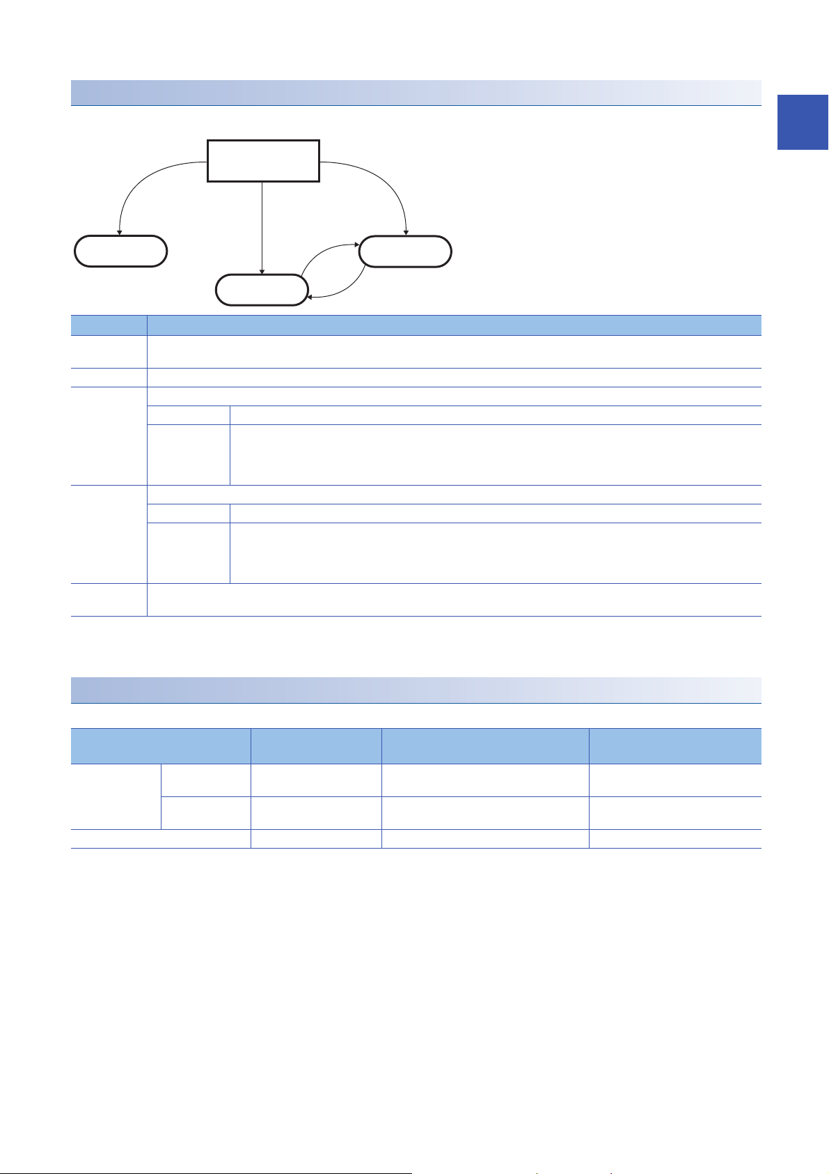
Mode transitions
At the power-on or at the
reset of the CPU module
(5)
(2)
(1)
(4)
(3)
Normal mode
Wave output mode
Offset/gain
setting mode
*1
The following figure and table describe the transition condition for each mode.
No. Transition condition
(1) Set "Operation mode setting" to "Normal mode (D/A conversion process)" in "Basic settig" of the engineering tool and set "Output mode
setting" to "Normal output mode".
(2) Set "Operation mode setting" to "Offset/gain setting mode” in "Basic settig" of the engineering tool.
(3) Perform the mode transition by either of the following methods.
Method 1 Execute the G(P).OFFGAN instruction (Argument "S": 0: Transition to the normal output mode).
Method 2 Set the following values for 'Mode switching setting' (Un\G296, Un\G297) and turn on and off 'Operating condition setting
request' (Y9).
• Un\G296: 5260H
• Un\G297: 4441H
(4) Perform the mode transition by either of the following methods.
Method 1 Execute the G(P).OFFGAN instruction (Argument "S": 1: Transition to the offset/gain setting mode).
Method 2 Set the following values for 'Mode switching setting' (Un\G296, Un\G297) and turn on and off 'Operating condition setting
request' (Y9).
• Un\G296: 4441H
• Un\G297: 5260H
(5) Set "Operation mode setting" to "Normal mode (D/A conversion process)" in "Basic settig" of the engineering tool and set "Output mode
setting" to "Wave output mode".
*1 The wave output mode is independent of the other modes. After the module is powered on in the wave output mode, the transition to the
other modes is disabled.
After the module is powered on in any mode other than the wave output mode, the transition to the wave output mode is also disabled.
1
Checking method
The currently selected mode can be checked with the following items.
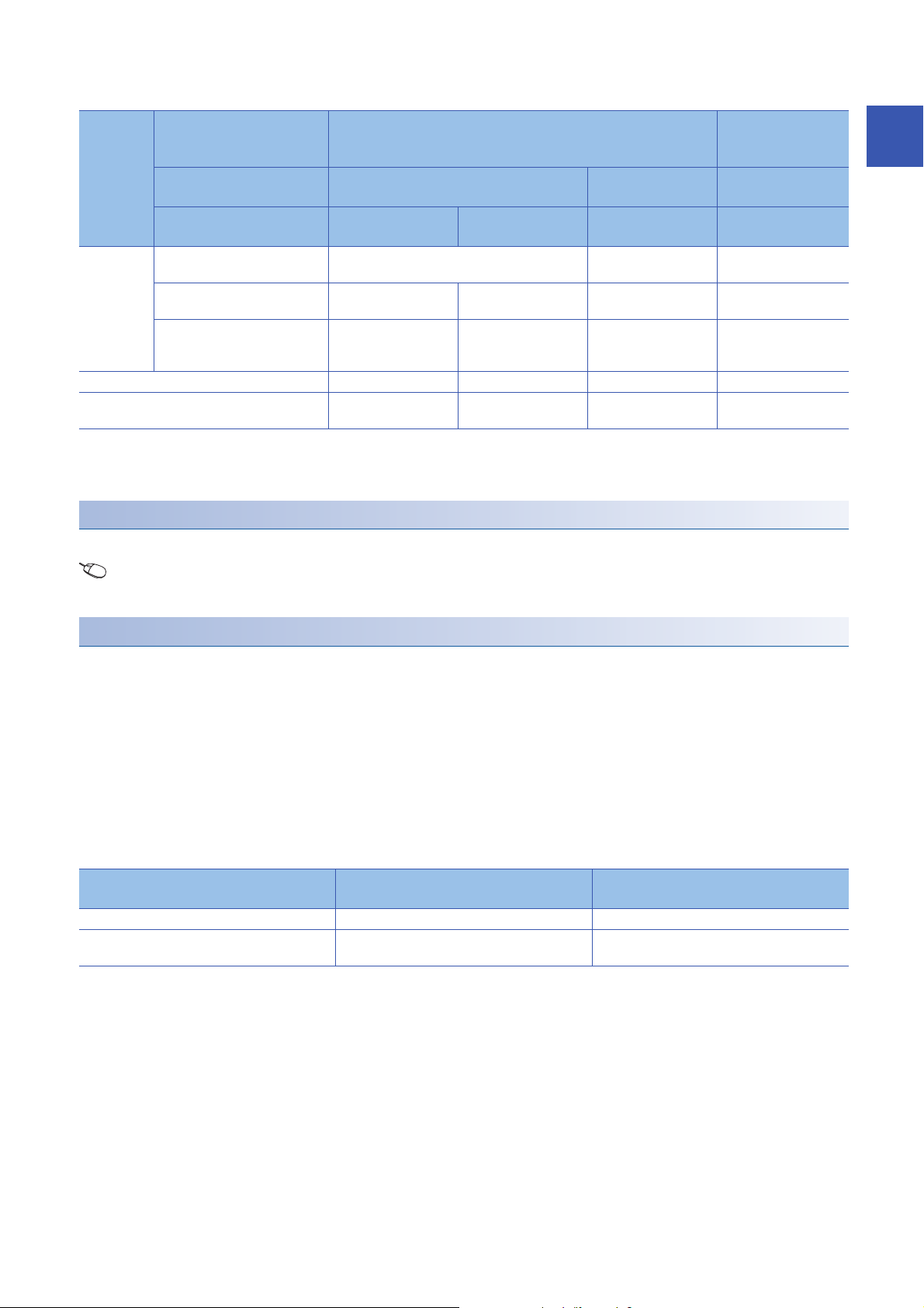
Mode RUN LED status Stored value of 'Output mode'
Normal mode Normal output
Offset/gain setting mode Flashing 0 ON
*1 When 'User range write request' (YA) is off
'Offset/gain setting mode
(Un\G60)
mode
Wave output
mode
ON 0 OFF
ON 1 OFF
status flag' (XA)
*1
*1
1 FUNCTIONS
1.1 Modes
17
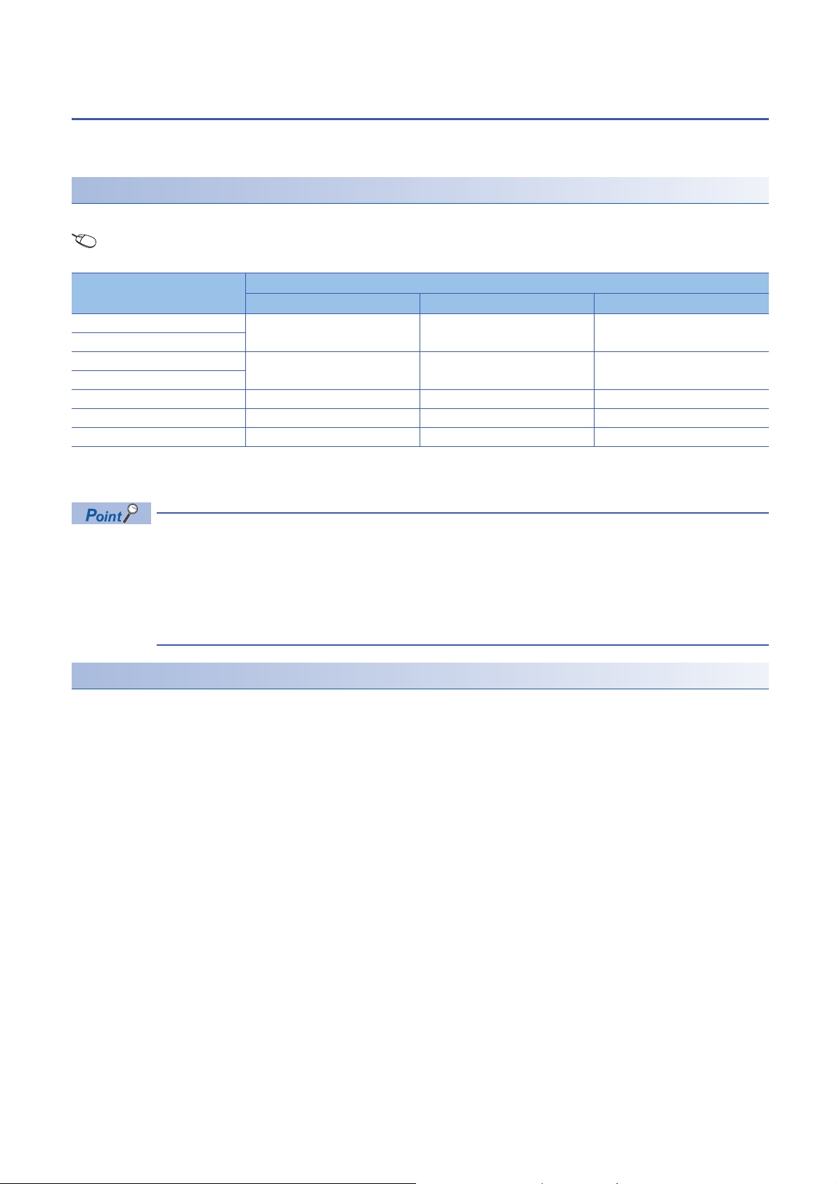
1.2 Range Switching Function
The output range of the analog output can be switched for each channel.
Switching the range makes it possible to change the I/O conversion characteristic.
Setting procedure
Set the output range to be used in "Output range setting".
Navigation window [Parameter] [Module Information] Module name [Module parameter] "Basic settig"
"Range switching function"
Output range setting Digital input range
R60DA4 R60DAV8 R60DAI8
4 to 20mA 0 to 32000 0 to 32000
0 to 20mA
1 to 5V 0 to 32000 0 to 32000
0 to 5V
-10 to 10V -32000 to 32000 -32000 to 32000
User range (Voltage) -32000 to 32000 -32000 to 32000
User range (Current) -32000 to 32000 -32000 to 32000
After the data is written, the range is switched when the programmable power supply is turned off and on or when the CPU
module is reset.
The following buffer memory areas are used to monitor the range setting and to switch the range.
• 'CH1 Range setting' (Un\G598)
• 'CH1 Range setting monitor' (Un\G430)
For details on the buffer memory areas, refer to the following.
Page 164 CH1 Range setting
Page 145 CH1 Range setting monitor
Precautions
The output range cannot be changed for channels set to D/A conversion disabled. To change the output range, set "D/A
conversion enable/disable setting" to "D/A conversion enabled" and 'CH1 Output enable/disable flag' (Y1) to OFF.
18
1 FUNCTIONS
1.2 Range Switching Function

1.3 D/A Conversion Enable/Disable Function
Set whether to enable or disable the D/A conversion for each channel.
Disabling the D/A conversion for unused channels reduces the D/A conversion cycles.
Setting procedure
Set "D/A conversion enable/disable setting" to "D/A conversion enable” or "D/A conversion disable".
Navigation window [Parameter] [Module Information] Module name [Module parameter] "Basic settig"
"D/A conversion enable/disable function"
1.4 D/A Output Enable/Disable Setting Function
Specify whether to output the D/A conversion value or offset value for each channel.
The conversion speed is a constant, regardless of the output enable/disable state.
Setting procedure
Set to enable or disable the D/A output for each channel with 'CH1 Output enable/disable flag' (Y1).
'CH1 Output enable/disable flag' (Y1) Analog output
Enable (ON) The D/A conversion value is output.
Disable (OFF) The offset value is output.
1
1 FUNCTIONS
1.3 D/A Conversion Enable/Disable Function
19
1.5 Analog Output HOLD/CLEAR Function
Set whether to hold or clear the analog output value that has been output when the operating status of the CPU module is
RUN, STOP, or stop error.
The HOLD/CLEAR setting can be checked with 'CH1 HOLD/CLEAR function setting monitor' (Un\G431).
Operation
When the operating status of the CPU module is RUN, STOP, or stop error, the analog output status changes as shown in the
following table, depending on the combination of the settings of the analog output HOLD/CLEAR setting, 'CH1 D/A conversion
enable/disable setting' (Un\G500), and 'CH1 Output enable/disable flag' (Y1).
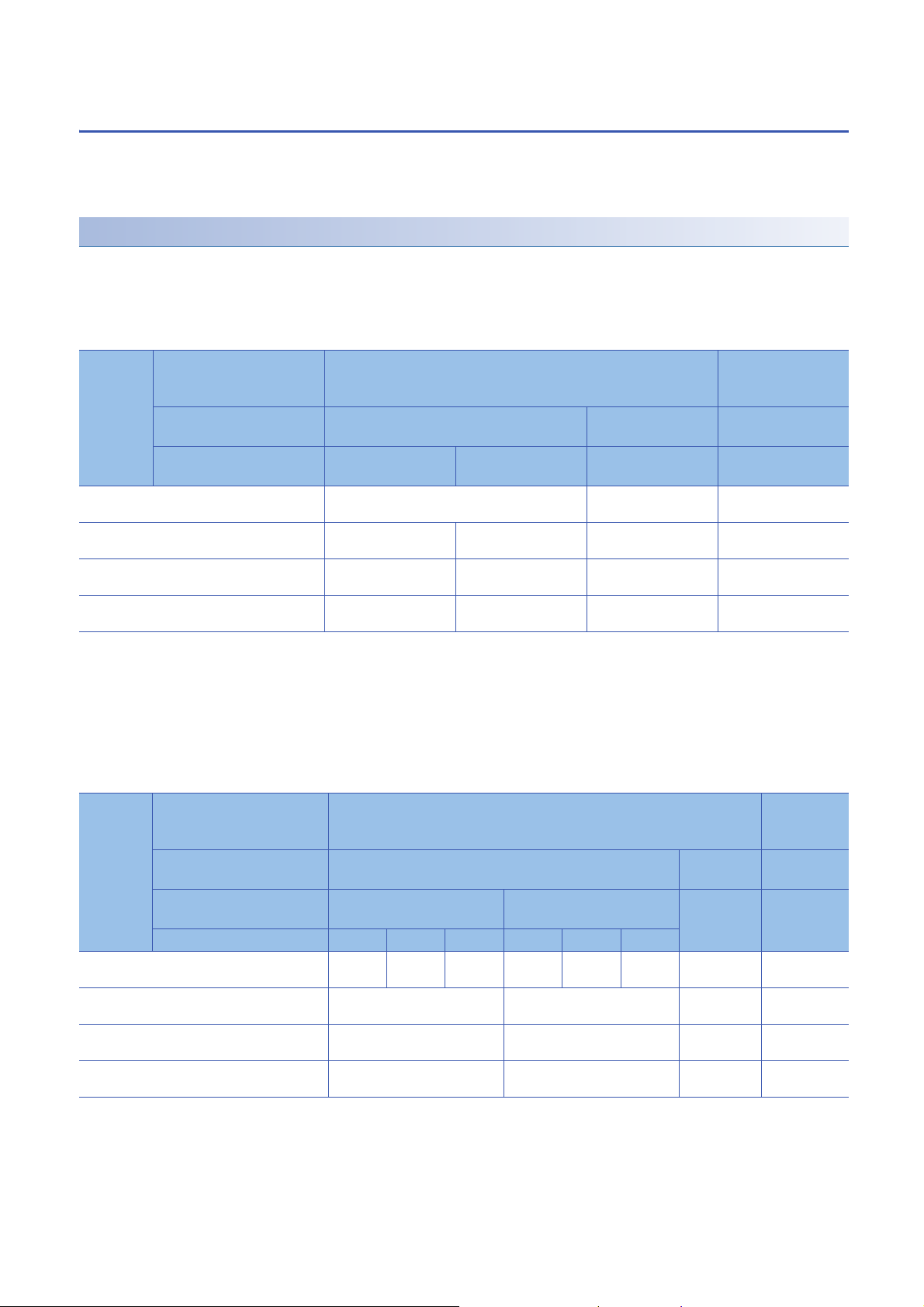
■In the normal output mode
Execution
status
Analog output produced when the CPU module
is in the RUN status
Analog output produced when the CPU module
is in the STOP state
Analog output produced when the CPU module
is in the stop error state
Analog output produced when a watchdog timer
*1
error
CH1 D/A conversion
enable/disable setting
(Un\G500)
CH1 Output enable/disable
flag (Y1)
Analog output HOLD/
CLEAR setting
occurs
Enable Disable
Enable Disable Enable or disable
HOLD CLEAR HOLD or CLEAR HOLD or CLEAR
The digital value converted in analog is output. Offset value 0V/0mA
Hold Offset value Offset value
Hold Offset value Offset value 0V/0mA
0V/0mA 0V/0mA 0V/0mA 0V/0mA
*2
0V/0mA
*1 The error occurs due to a hardware failure of the D/A converter module or other causes. 'Module READY' (X0) and the RUN LED of the
D/A converter module turn off.
When a watchdog timer error occurs, 'Module READY' (X0) and the RUN LED of the D/A converter module turn off.
*2 The following operation is performed when the CPU module is in the STOP state, the D/A conversion enable/disable setting is set to D/
A conversion enable (0) for the channel where HOLD is set, and 'Operating condition setting request' (Y9) is turned on and off.
When Output enable/disable flag is off: Outputs 0V/0mA.
When Output enable/disable flag is turned on: Outputs the offset value.
■In the wave output mode
Execution
status
Analog output produced when the CPU module is
in the RUN status
Analog output produced when the CPU module is
in the STOP state
Analog output produced when the CPU module is
in the stop error state
Analog output produced when a watchdog timer
*1
error
CH1 D/A conversion
Enable Disable
enable/disable setting
(Un\G500)
CH1 Output enable/disable
Enable Disable Enable or
flag (Y1)
Analog output HOLD/
HOLD CLEAR HOLD or
CLEAR setting
Wave output status Output Stop Pause Output Stop Pause
Wave
data
Hold Offset value Offset value 0V/0mA
Hold Offset value Offset value 0V/0mA
0V/0mA 0V/0mA 0V/0mA 0V/0mA
occurs
*2
Hold Wave
data
disable
HOLD or
CLEAR
*2
Offset
value
Offset value 0V/0mA
CLEAR
*1 The error occurs due to a hardware failure of the D/A converter module or other causes. 'Module READY' (X0) and the RUN LED of the
D/A converter module turn off.
When a watchdog timer error occurs, 'Module READY' (X0) and the RUN LED of the D/A converter module turn off.
*2 The output set in 'CH1 Output setting during wave output stop' (Un\G524).
1 FUNCTIONS
20
1.5 Analog Output HOLD/CLEAR Function
■In the synchronization normal output mode
Execution
status
External
power
supply
READY flag
(X7): On
External power supply READY flag (X7): Off 0V/0mA 0V/0mA 0V/0mA 0V/0mA
Analog output produced when a watchdog timer
*1
error
*1 The error occurs due to a hardware failure of the D/A converter module or other causes. 'Module READY' (X0) and the RUN LED of the
D/A converter module turn off.
When a watchdog timer error occurs, 'Module READY' (X0) and the RUN LED of the D/A converter module turn off.
CH1 D/A conversion
enable/disable setting
(Un\G500)
CH1 Output enable/disable
flag (Y1)
Analog output HOLD/
CLEAR setting
Analog output produced when the
CPU module is in the RUN status
Analog output produced when the
CPU module is in the STOP state
Analog output produced when the
CPU module is in the stop error
state
occurs
Enable Disable
Enable Disable Enable or disable
HOLD CLEAR HOLD or CLEAR HOLD or CLEAR
CH1 Synchronization digital value (Un\G9500) Offset value 0V/0mA
Hold Offset value Offset value
Hold Offset value Offset value 0V/0mA
0V/0mA 0V/0mA 0V/0mA 0V/0mA
*2
0V/0mA
Setting procedure
Set "Analog output HOLD/CLEAR setting" to "HOLD" or "CLEAR".
Navigation window [Parameter] [Module Information] Module name [Module parameter] "Basic settig"
"Output mode setting function"
1
Precautions for when the remote head module has been mounted
When the D/A converter module has been mounted on the remote head module, set whether to hold or clear the analog
output value that has been output when the host station is disconnected with "CPU error output mode setting" of the module
parameter.
The following describes the settings required for using "CPU error output mode setting".
• Enable the station-based block data assurance for cyclic data on the sending side.
• To hold the analog output value, set "CPU error output mode setting" to "Hold". The analog output HOLD/CLEAR function
setting is disabled.
This setting is enabled for each module and cannot be set for each channel. To match the output status of when a stop error
occurs or the CPU module is in the STOP state and that of when the host station is disconnected, set "Analog output HOLD/
CLEAR setting" to the same value in all the channels.
Operating status CPU error output mode setting
The analog output value is held. Hold HOLD
The analog output value is cleared.
(The offset value is output.)
*1 "CPU error output mode setting" is enabled in the following cases.
When the host station is disconnected due to a network error
When the data link is stopped by the CC-Link IE Field Diagnostics of the engineering tool
Clear CLEAR
*1
Analog output HOLD/CLEAR setting
(Set the same value in all the channels.)
1 FUNCTIONS
1.5 Analog Output HOLD/CLEAR Function
21
1.6 Analog Output Test when CPU Module is in STOP
RUN
Offset value
OFF
*1
OFF
ON
*2
ON
Offset value
RUNSTOP
D/A-converted value is output even when the CPU module is in STOP status.
Analog output value
converted from digital value
Analog output value
converted from digital value
Analog output value
converted from digital value
CH1 Output
enable/disable
flag (Y1)
Analog output
value status
CPU module
status
Controlled by the D/A converter module
Status Function
Analog output tests can be carried out when the CPU module is in the STOP status.
The following functions are enabled during the analog output test.
• Scaling function (Page 23 Scaling Function)
• Shift function (Page 26 Shift Function)
• Alert output function (Page 28 Alert Output Function)
When a digital value that is out of the setting range is written, a digital value setting range error (error code: 191H) occurs
and the corresponding check code is stored in 'CH1 Setting value check code' (Un\G400).
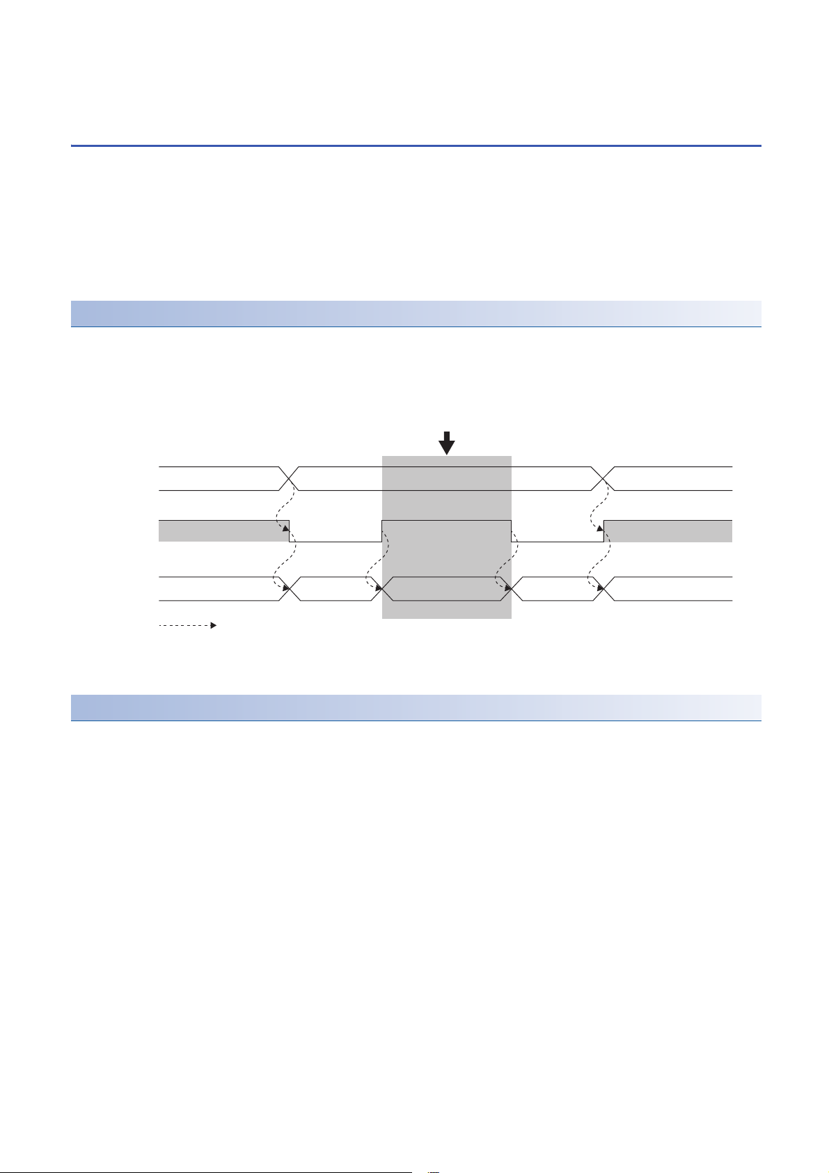
Operation
By forcibly turning on 'CH1 Output enable/disable flag' (Y1) when the CPU module is in the STOP state, the analog output
value is changed from the offset value to the D/A-converted analog output value.
The following figure shows the relation between 'CH1 Output enable/disable flag' (Y1) and the analog output value of the CPU
module in the STOP state when the analog output HOLD/CLEAR setting is set to CLEAR (0).
*1 'CH1 Output enable/disable flag' (Y1) turns off when the status of the CPU module is changed into STOP.
*2 By forcibly turning on 'CH1 Output enable/disable flag' (Y1), the analog output value is changed from the offset value to the D/A-
converted analog output value.
Setting procedure
To perform an analog output test, configure the settings in the device test of the engineering tool following the procedure
shown below.
1. Set 'CH1 D/A conversion enable/disable setting' (Un\G500) of the buffer memory to D/A conversion enabled (0).
2. Turn on 'Operating condition setting request' (Y9).
3. Check that 'Operating condition setting completed flag' (X9) turns off, and turn off 'Operating condition setting request'
(Y9).
4. Set the digital value equivalent to the analog value to be output for 'CH1 Digital value' (Un\G460) in the buffer memory.
5. Turn on 'CH1 Output enable/disable flag' (Y1).
22
1 FUNCTIONS
1.6 Analog Output Test when CPU Module is in STOP Status Function

1.7 Scaling Function
× (DX - SL)
SH - S
L
32000
=
Digital value used for D/A
conversion
SH - S
L
64000
× (DX - SL) - 32000
Digital value used for D/A
conversion
=
× (DX - SL)
SH - S
L
32000
=
Digital value used for D/A
conversion
This function performs the scale conversion on digital values within a specified range between a scaling upper limit value and
a scaling lower limit value. The program for scale conversion can be omitted.
Operation
The scale conversion is performed for the set 'CH1 Digital value' (Un\G460) using 'CH1 Scaling upper limit value' (Un\G504)
and 'CH1 Scaling lower limit value' (Un\G506), and the value after the scale conversion is used for the D/A conversion. (In the
scale conversion, values after the decimal point are rounded off.)
When the relation between the set upper limit value and lower limit value is Scaling lower limit value > Scaling upper limit
value, the scale conversion can be performed according to a negative slope.
Concept of scaling setting
The necessary settings for the scaling lower limit value and scaling upper limit value depend on whether the factory default
setting or the user range setting is used for the analog output range.
■When the factory default setting is used for the analog output range
• For the scaling upper limit value, set a value corresponding to the upper limit value of the set analog output value.
• For the scaling lower limit value, set a value corresponding to the lower limit value of the set analog output value.
■When the user range setting is used for the analog output range
• Set a value corresponding to the gain value for the scaling upper limit value.
• Set a value corresponding to the offset value for the scaling lower limit value.
1
Calculating the scaling value
For D/A conversion, the scaling value is calculated based on the following equations.
■When the factory default setting is used for the output range
• When the voltage is 1 to 5V or 0 to 5V and the current is 4 to 20mA or 0 to 20mA
• When the voltage is -10 to 10V
■When the user range setting is used for the output range
Item Description
D
X
S
H
S
L
Digital value
Scaling upper limit value
Scaling lower limit value
1 FUNCTIONS
1.7 Scaling Function
23
Setting procedure
Ex.
0
5
0
32000
Analog output voltage (V)
Scaling lower limit
value 4000
Scaling upper limit
value 14000
Digital value
1. Set "D/A conversion enable/disable setting" to "D/A conversion enable".
Navigation window [Parameter] [Module Information] Module name [Module parameter] "Basic settig"
"D/A conversion enable/disable function"
2. Set "Scaling enable/disable setting" to "Enable".
Navigation window [Parameter] [Module Information] Module name [Module parameter] "Application
setting" "Scaling setting"
3. Set values for "Scaling upper limit value" and "Scaling lower limit value".
Set the values to satisfy the following relation.
Scaling upper limit value Scaling lower limit value
Item Setting range
Scaling upper limit value -32000 to 32000
Scaling lower limit value
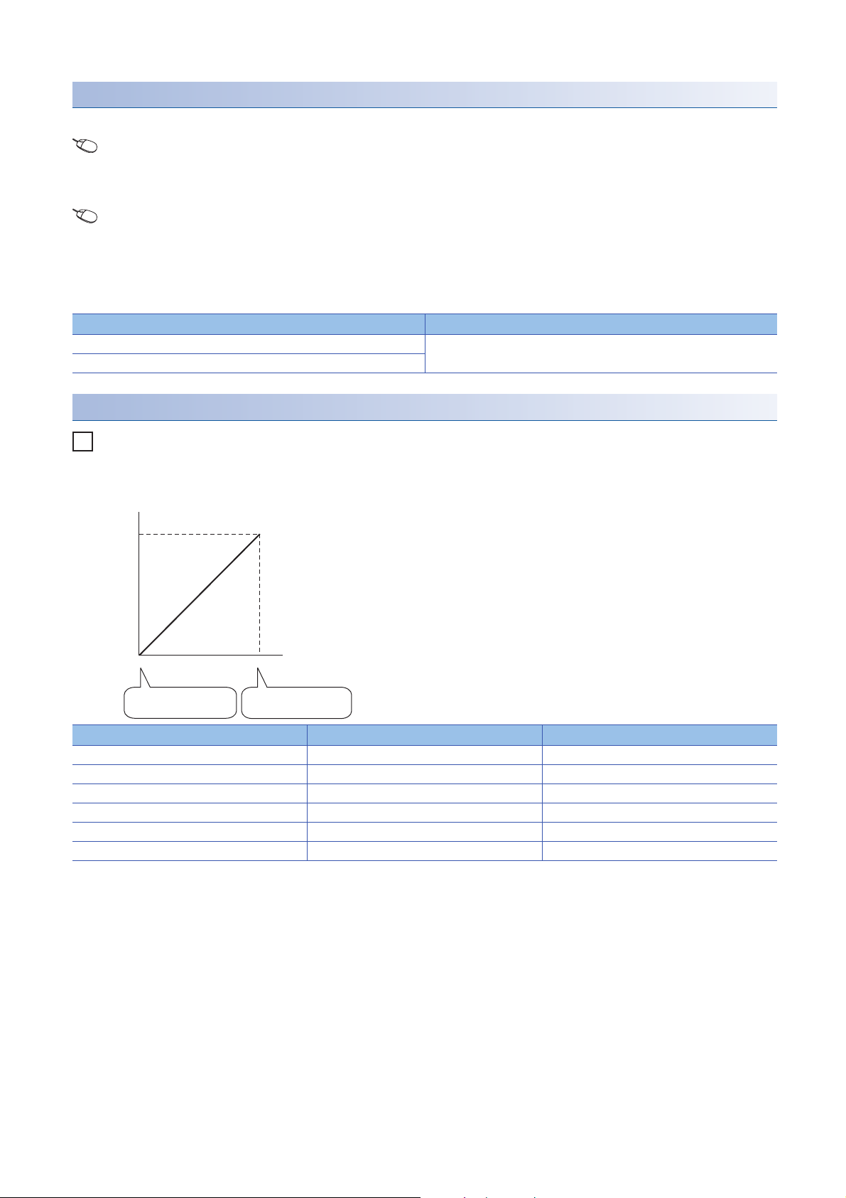
Example of scaling setting
When 14000 is set to the scaling upper limit value and 4000 is set to the scaling lower limit value for the channel with the
output range of 0 to 5V
Digital value Digital value after scaling Output voltage (V)
4000 0 0
6000 6400 1
8000 12800 2
10000 19200 3
12000 25600 4
14000 32000 5
24
1 FUNCTIONS
1.7 Scaling Function

Precautions
• When the scaling function is used, the digital value can be set to a value out of the range between the scaling upper limit
value and scaling lower limit value (in the dotted lines in the I/O characteristics graph) before being scaled. However, use
the scaling function within the range of the analog output practical range (in the solid line in the I/O characteristics graph). If
the value exceeds the analog output practical range, the maximum resolution and accuracy may not fall within the range of
the performance specifications.
• The default digital value "0" may not be appropriate, depending on the scaling function setting.
In particular in the examples of when the output range is 0 to 5V, an out-of-range digital value error occurs if 'CH1 Output
enable/disable flag' (Y1) is turned on with the digital value "0".
A digital value setting range error (error code: 191H) occurs and 'Error flag' (XF) turns on, and the ERR LED lights.
Therefore, set an appropriate digital value within the scaling range before turning on 'CH1 Output enable/disable flag' (Y1).
• When using the user range, note that the scaling lower limit value is equal to the offset value.
• When the scaling function is enabled and the digital value after the scaling conversion is out of the digital setting range, a
digital value setting range error (error code: 191H) occurs and the corresponding check code is stored in 'CH1 Setting
value check code' (Un\G400).
• The scaling function is enabled only for the normal output. When the scaling function is enabled while the wave output
function is used, a scaling setting error in wave output mode (error code: 0B1H) occurs and 'Alert output signal' (XE) turns
on.
1
1 FUNCTIONS
1.7 Scaling Function
25
1.8 Shift Function
Ex.
0
5
0
32000
31950
-50
Analog output voltage (V)
Input value
shift
After
adjustment
Before
adjustment
digital value
This function adds the set input value shift amount to the digital input value.
The analog output value reflects the change in the input value shift amount on a realtime basis. Therefore, fine adjustment
can be easily performed when the system starts.
Operation
When the D/A conversion is performed on the digital value, the value obtained by adding 'CH1 Input value shift amount'
(Un\G480) to 'CH1 Digital value' (Un\G460) is used for the D/A conversion.
When the digital value after the addition exceeds the range of -32768 to 32767 as the result of the shift processing, the value
is fixed with the lower limit value (-32768) or the upper limit value (32767).
When a value is written to 'CH1 Input value shift amount' (Un\G480), the set value is added to the digital input value
regardless of the ON/OFF state of 'Operating condition setting request' (Y9).
Setting procedure
Set the shift amount to "Input value shift amount".
Navigation window [Parameter] [Module Information] Module name [Module parameter] "Application
setting" "Shift function"
Item Setting range
Input value shift amount -32768 to 32767
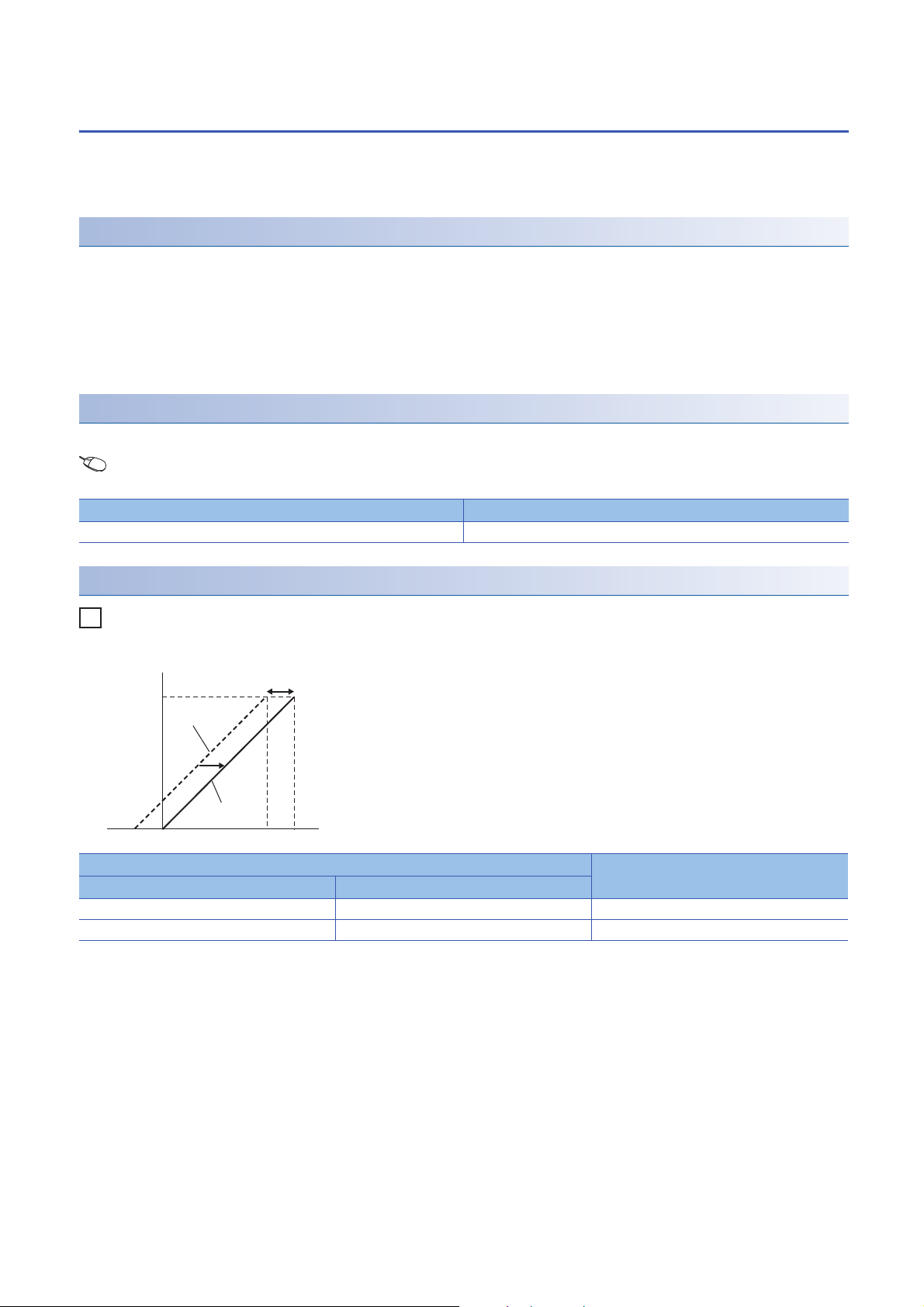
Setting example
When the output range is 0 to 5V and the input value shift amount is +50
Digital value Analog output voltage (V)
Before adjustment After adjustment
-50 0 0
31950 32000 5
1 FUNCTIONS
1.8 Shift Function
26

Precautions
• Based on the digital value on which the shift-and-add is performed, the alert output function, scaling function, and rate
control function are executed.
• When the value obtained by adding 'CH1 Input value shift amount' (Un\G480) to 'CH1 Digital value' (Un\G460) is out of the
digital setting range, a digital value setting range error (error code: 191H) occurs and the corresponding check code is
stored in 'CH1 Setting value check code' (Un\G400).
• The shift function is enabled only for the normal output. When a value other than 0 is set in 'CH1 Input value shift amount'
(Un\G480) while the wave output function is used, an input value shift amount setting error in wave output mode (alarm
code: 0B2H) occurs and 'Alert output signal' (XE) turns on. Although the wave output continues, 'CH1 Input value shift
amount' (Un\G480) is not added to the wave data to be output.
• Even though 0 is set for 'CH1 Input value shift amount' (Un\G480) after an input value shift amount setting error in wave
output mode has occurred, 'Alert output signal' (XE) does not turn off. Turn on and off 'Alert output clear request' (YE) to
turn off 'Alert output signal' (XE). By this operation, 'Alert output signal' (X8) and the ALM LED turn off, and Latest alarm
code is cleared.
1
1 FUNCTIONS
1.8 Shift Function
27
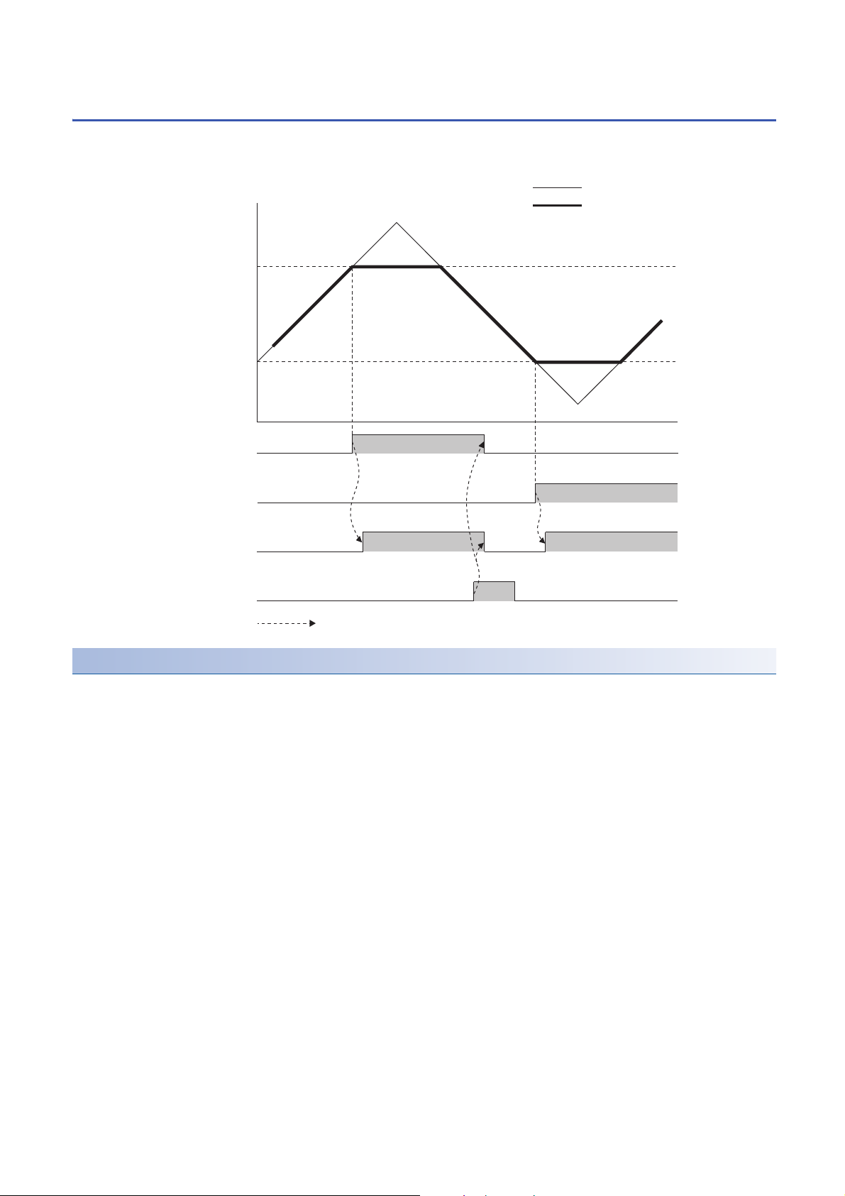
1.9 Alert Output Function
CH1 Alert output upper limit value
OFF ON
Alert output signal (XE)
OFF
OFF ON
CH1 Alert output lower limit value
20000
-2000
Digital value
Alert output upper flag
Alert output lower flag
Alert output clear request (YE)
OFF
Digital value
Analog output value
ON ON
ON OFF
OFF
OFF
Controlled by the D/A converter module
This function outputs an alert when the digital value is larger than the alert output upper limit value or is smaller than the alert
output lower limit value.
Operation
■Alert output notification
When 'CH1 Digital value' (Un\G460) is larger than 'CH1 Alert output upper limit value' (Un\G510) or is smaller than 'CH1 Alert
output lower limit value' (Un\G512), either of 'Alert output upper limit flag' (Un\G36) or 'Alert output lower limit flag' (Un\G37),
'Alert output signal' (XE), and the ALM LED turn on to output an alert. In addition, an alarm code (080H or 081H) is stored
in 'Latest alarm code' (Un\G2) when an alert has occurred.
When an alert has occurred, the set value of the alert output upper limit value or the alert output lower limit value is used as
the digital value for the D/A conversion.
When 'CH1 Digital value' (Un\G460) is changed to a value smaller than 'CH1 Alert output upper limit value' (Un\G510) and
larger than 'CH1 Alert output lower limit value' (Un\G512) after an alert has occurred, the analog output value returns to a
normal value. However, 'Alert output upper limit flag' (Un\G36), 'Alert output lower limit flag' (Un\G37), and 'Alert output signal'
(XE) are not cleared.
28
1 FUNCTIONS
1.9 Alert Output Function
 Loading...